© Qube Engineering 2010 LED Gauge Cluster Installation Instructions – AP2_1.x v1.0 Page 1 V1.0 Qube Engineering 21914 Palos Verdes Blvd Torrance, CA 90503 818-271-QUBE (7823) [email protected] © Qube Engineering 2010 NOTE – Some images in this document may be taken from another vehicle model year than the product is intended. However, when steps are specific to the AP2 installation procedure, AP2 pictures are shown.

Welcome message from author
This document is posted to help you gain knowledge. Please leave a comment to let me know what you think about it! Share it to your friends and learn new things together.
Transcript

© Qube Engineering 2010 LED Gauge Cluster Installation Instructions – AP2_1.x v1.0 Page 1 V1.0
Qube Engineering 21914 Palos Verdes Blvd
Torrance, CA 90503 818-271-QUBE (7823)
© Qube Engineering 2010
NOTE – Some images in this document may be taken from another vehicle model year than the product is intended. However, when steps are specific to the AP2 installation
procedure, AP2 pictures are shown.

© Qube Engineering 2010 LED Gauge Cluster Installation Instructions – AP2_1.x v1.0 Page 2
Modified Gauge Cluster Face Power Connection Cable
Cable Ties
(CORE EXCHANGE VERSION) If your package does not contain all of the following parts, please contact
Qube Engineering before continuing.
Owner’s Manual
Fuse Box Power Splitter
Power Connector
Screw Cap Removal Tool
Brightness Control Connector

© Qube Engineering 2010 LED Gauge Cluster Installation Instructions – AP2_1.x v1.0 Page 3
Low Adhesive Tape (Painter’s Tape)
Short Philips Screwdriver
or
Thin Flathead Screwdriver
Medium / Long Philips Screwdriver
Scissors
Ratchet, Extension Bar, 10mm and 12mm Socket
Ratchet
Extension Bar
12mm Socket
Flashlight
10mm Socket
(CORE EXCHANGE VERSION)
© Qube Engineering 2010 LED Gauge Cluster Installation Instructions – AP2_1.x v1.0 Page 4
1) Although not absolutely necessary for the LED Gauge Cluster Installation, it is always a good idea to disconnect the battery when doing any work on your car.
4) After removing the lower steering column cover, two 12mm nuts near the front of the steering column will be accessible. Using the ratchet, extension bar, and 12mm socket, remove the two nuts from the front of the steering column. Put the nuts aside.
2) Using the long Philips screwdriver, remove the three screws that hold the lower steering column cover in place. Put the screws aside.
Tabs
Rubber Ring
12mm Nuts
3) The lower steering column cover is held in place with four tabs. While pulling on the rear of the lower column cover, wiggle each corner where the tabs are located to dislodge them. It may take a hard tug to remove the cover. Keep the rubber ring around the ignition key hole with the lower steering column cover.
Disconnect Battery

© Qube Engineering 2010 LED Gauge Cluster Installation Instructions – AP2_1.x v1.0 Page 5
5) Again using the ratchet, extension bar, and 12mm socket, loosen but DO NOT REMOVE the two nuts that hold the U-shaped clamp further down the length of the steering column. The ratchet extension bar will be touching the black plastic knee guard as you loosen the bolts. Alternate loosening the bolts, so both bolts are basically being loosened at the same time. As you loosen both bolts, the steering column will begin to descend. Loosen both bolts until the steering column descends to the angle shown here. DO NOT PUT ANY UNNECESSARY DOWNWARD FORCE ON THE STEERING COLUMN OR STEERING WHEEL.
7) Locate the included Screw Cap Removal Tool. It should very closely resemble a bent paper clip ;).
Screw Covers
Black Plastic Knee Guard
About 3 Inches 12mm Bolts
6) Remove the top half of the steering wheel cover and set it aside.

© Qube Engineering 2010 LED Gauge Cluster Installation Instructions – AP2_1.x v1.0 Page 6
8) Notice the “flat” side of the screw covers on the side closest to the steering wheel. Insert the small hook end of the paper clip into the groove between the flat area and the dashboard until the paper clip hook grabs onto the shelf of the screw cover. Pull the screw covers out and set them aside.
Screw Cover “flat” side
Screw Cover “shelf”
9) Using the short Philips screwdriver, remove the two screws that were behind the screw covers. Set the screws aside.
11) Starting from the inside corner of the dashboard gauge panel, pull the panel until the first clip becomes detached from the main dashboard part. You should feel a slow “pop” as the clip becomes detached.
10) To avoid scratches, use the low adhesive tape to cover the area where the Dash Bezel will come into contact with the turn signal lever as you remove it. Tape Both the dash bezel and the turn signal lever. Feel free to use 2-3 layers on each side just to be safe.

© Qube Engineering 2010 LED Gauge Cluster Installation Instructions – AP2_1.x v1.0 Page 7
13) While holding the dashboard gauge panel away from the main dashboard, undo the following electrical harnesses… 1) Engine Start Button 2) Audio Controls 3) Cruise Control Switch 4) Defroster Switch or VSA switch 5) A/C Controls
12) Continue pulling the sides of the dashboard gauge panel removing the rest of the clips around the dashboard gauge panel. There are 10 clips total including the clip from the previous step.
Clip Locations
14) Remove the dashboard gauge panel from the vehicle and place it on a soft, flat surface like a carpet or towel so as not to scratch it. Keep the low adhesive tape on the gauge panel for now.
15) Using the short Philips screwdriver, remove the two black screws at the forward end of the brass brackets that hold the gauge cluster in place and the two black screws at the lower corners of the gauge cluster.
© Qube Engineering 2010 LED Gauge Cluster Installation Instructions – AP2_1.x v1.0 Page 8
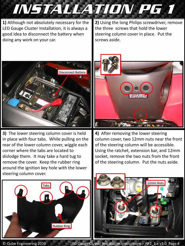
16) Pull the gauge cluster forward and remove the two brass screws that hold the brass brackets onto the gauge cluster. Set aside the brass brackets and screws.
17) Tilt the gauge cluster forward to expose the wire harnesses in back. Using a flat screwdriver with masking tape on the end, push the wire harness tab downward while prying the harness away from the gauge cluster. Unplug both wire harnesses.
18) Set your stock gauge cluster face down on a soft surface such as a towel.
Flat Screwdriver with Masking Tape
Stock Gauge Cluster (from back)
19) Remove the three brass screws from the back of your stock gauge cluster. Using a small flathead screwdriver to unhook the tabs around the perimeter of the white plastic back cover of the gauge cluster, remove the back cover.

© Qube Engineering 2010 LED Gauge Cluster Installation Instructions – AP2_1.x v1.0 Page 9
20) With the gauge cluster computer board exposed, unplug the two light blue ribbon cables. Place the head of a large flathead screwdriver to in the flat area of the ribbon harness and twist to unplug the harness.
21) Unplug the two small wire harnesses with the black and white wires. You should be able to do by gently wiggling the harness out. Use a small flathead screwdriver to help release the harness if necessary.
22) Carefully remove the thin copper colored ribbon cable from the harness. Do this by first pulling up on the sides of the locking mechanism, then pulling the ribbon cable out of the harness.
GAUGE CLUSTER COMPUTER BOARD
STOCK GAUGE CLUSTER FACE ASSEMBLY
23) While moving the ribbon cables out of the way, lift out the green gauge cluster computer board from the front of your stock gauge cluster.
Twist
Unlock Harness
Remove Cable
© Qube Engineering 2010 LED Gauge Cluster Installation Instructions – AP2_1.x v1.0 Page 10
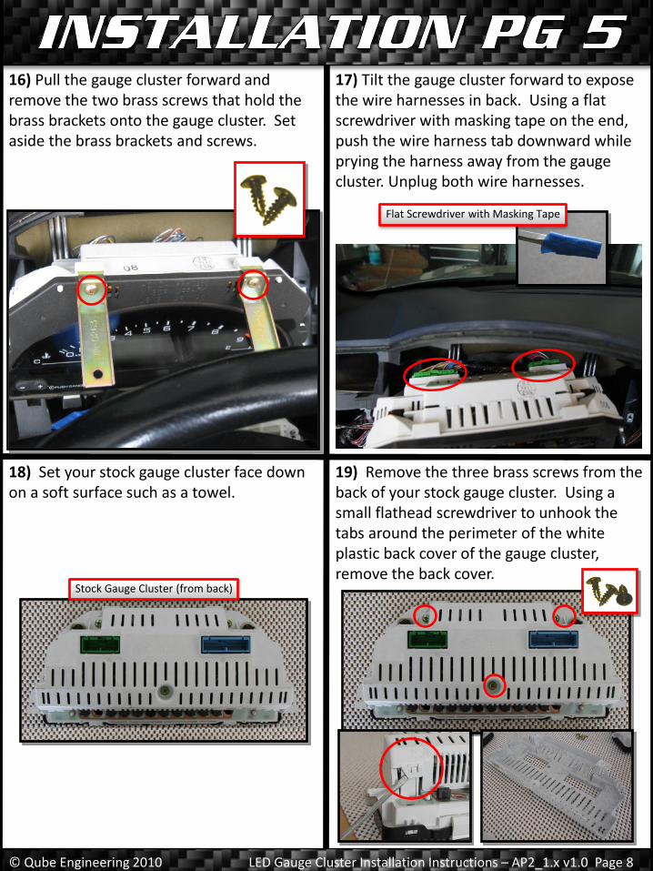
25) Plug all harnesses snugly back into place. Make sure to reengage the locking mechanism for the copper ribbon cable. The long gray 4-pin ribbon cable from the LED array plugs into the 4-pin harness on the bottom right of the gauge cluster computer. Make sure to press it all the way in. It is a tight fit.
26) While routing the black and red cables through the bottom side of the assembly as shown, snap the back cover of the housing back onto the gauge cluster assembly. Reattach the three screws that hold the back cover in place. Set the assembly aside for now.
24) While moving the ribbon cables out of the way, install your gauge cluster computer onto the backside of the modified gauge cluster assembly.
IF YOU ORDERED THE DO-IT-YOURSELF VERSION OF THE
GAUGE CLUSTER, PLEASE COMPLETE THE DO-IT-
YOURSELF SUPPLEMENTAL INSTRUCTIONS AT THIS POINT
BEFORE PROCEEDING.
© Qube Engineering 2010 LED Gauge Cluster Installation Instructions – AP2_1.x v1.0 Page 11
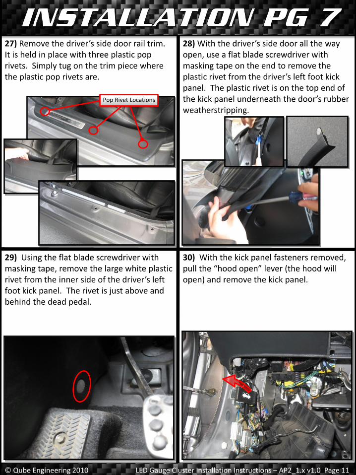
27) Remove the driver’s side door rail trim. It is held in place with three plastic pop rivets. Simply tug on the trim piece where the plastic pop rivets are.
28) With the driver’s side door all the way open, use a flat blade screwdriver with masking tape on the end to remove the plastic rivet from the driver’s left foot kick panel. The plastic rivet is on the top end of the kick panel underneath the door’s rubber weatherstripping.
29) Using the flat blade screwdriver with masking tape, remove the large white plastic rivet from the inner side of the driver’s left foot kick panel. The rivet is just above and behind the dead pedal.
Pop Rivet Locations
30) With the kick panel fasteners removed, pull the “hood open” lever (the hood will open) and remove the kick panel.
© Qube Engineering 2010 LED Gauge Cluster Installation Instructions – AP2_1.x v1.0 Page 12
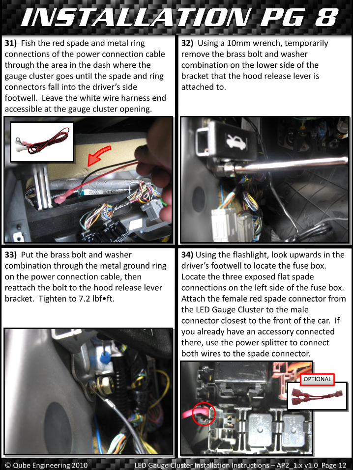
31) Fish the red spade and metal ring connections of the power connection cable through the area in the dash where the gauge cluster goes until the spade and ring connectors fall into the driver’s side footwell. Leave the white wire harness end accessible at the gauge cluster opening.
32) Using a 10mm wrench, temporarily remove the brass bolt and washer combination on the lower side of the bracket that the hood release lever is attached to.
33) Put the brass bolt and washer combination through the metal ground ring on the power connection cable, then reattach the bolt to the hood release lever bracket. Tighten to 7.2 lbf•ft.
34) Using the flashlight, look upwards in the driver’s footwell to locate the fuse box. Locate the three exposed flat spade connections on the left side of the fuse box. Attach the female red spade connector from the LED Gauge Cluster to the male connector closest to the front of the car. If you already have an accessory connected there, use the power splitter to connect both wires to the spade connector.
OPTIONAL
© Qube Engineering 2010 LED Gauge Cluster Installation Instructions – AP2_1.x v1.0 Page 13
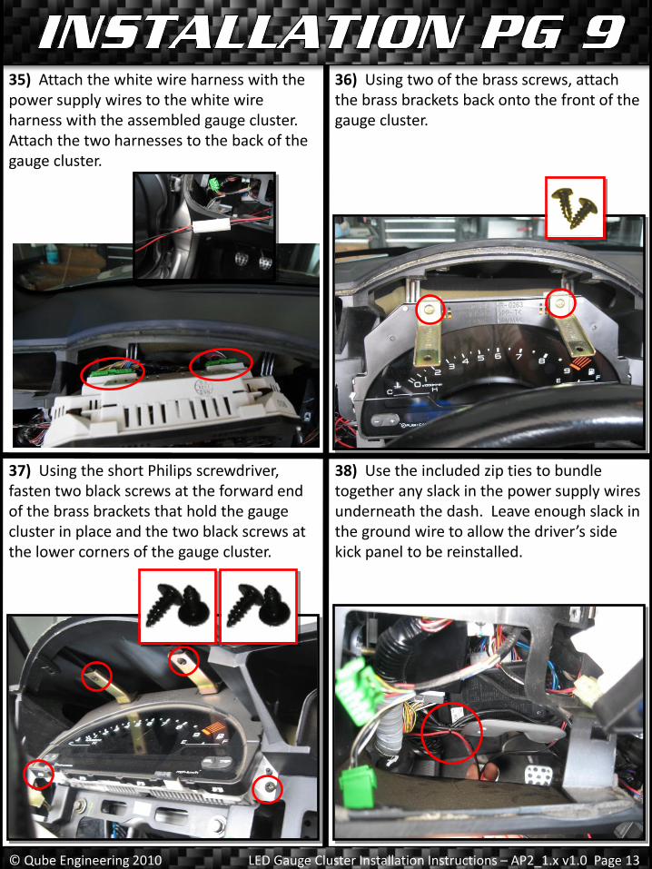
35) Attach the white wire harness with the power supply wires to the white wire harness with the assembled gauge cluster. Attach the two harnesses to the back of the gauge cluster.
36) Using two of the brass screws, attach the brass brackets back onto the front of the gauge cluster.
37) Using the short Philips screwdriver, fasten two black screws at the forward end of the brass brackets that hold the gauge cluster in place and the two black screws at the lower corners of the gauge cluster.
38) Use the included zip ties to bundle together any slack in the power supply wires underneath the dash. Leave enough slack in the ground wire to allow the driver’s side kick panel to be reinstalled.

© Qube Engineering 2010 LED Gauge Cluster Installation Instructions – AP2_1.x v1.0 Page 14
39) Snap the driver’s left foot kick panel and accompanying large white plastic rivet back into place. Push the driver’s side door rail trim back into place.
40) On the dashboard gauge panel, remove the Engine Start Button from the Audio Control Module. A plastic stud and a metal flat spring hold it in place. Compress the metal flat spring by pushing the Start Button assembly towards the metal spring side. Then push the plastic stud side inward and forward to remove the Start Button. Set both parts aside.
2 1
41) Put the gauge panel close enough to its normal location to reconnect the wire harnesses. While holding the dashboard gauge panel away from the main dashboard, reattach the electrical harnesses for the Engine Start Button through the hole in the Audio Control without clicking the Engine Start Button back into the Audio Control. The extra room behind the Start Button comes in handy when reattaching the panel in the next steps.
42) While still holding the dashboard gauge panel away from the main dashboard, reattach the electrical harnesses for the following… 1) Engine Start Button 2) Audio Controls 3) Cruise Control Switch 4) Defroster Switch or VSA switch 5) A/C Controls

© Qube Engineering 2010 LED Gauge Cluster Installation Instructions – AP2_1.x v1.0 Page 15
44) Put the upper steering column cover back into place.
43) Press the dashboard gauge panel back into place until all clips have been fastened. Clip the Start Button back into the Audio Control Module.
45) Raise the steering column, making sure the upper steering column cover does not become pinched between the steering column and the dashboard. Torque the two nuts near the steering wheel to 12 lbf•ft and the two bolts in the rear of the column to 16 lbf•ft.
Upper Cover
46) Reinstall the lower steering column cover. Make sure the rubber ring that surrounds the keyhole is aligned correctly. Use the three gold bolts with attached washers to secure the lower column cover in place.
Rubber Ring

© Qube Engineering 2010 LED Gauge Cluster Installation Instructions – AP2_1.x v1.0 Page 16
47) Using the short philips screwdriver, replace the two screws on the underside of the dash hood. Replace the screw covers as well.
48) If you disconnected the battery at the start of the installation, reconnect it at this time. Make sure to close your hood as well.
Installation Complete!
Reconnect Battery

© Qube Engineering 2010 LED Gauge Cluster Installation Instructions – AP2_1.x v1.0 Page 17
Congratulations on your purchase and installation of Qube’s LED Gauge Cluster for the AP2 v1.x. Please refer to the included Owner’s Manual for operating instructions. To complete the core exchange program, please send your stock gauge cluster face to…
Qube Engineering
21914 Palos Verdes Blvd Torrance, CA 90503
818-271-QUBE (7823) c/o Art Timbol
Please return your parts within two weeks of receiving your LED Gauge Cluster to avoid any additional fees. For your convenience and the protection of your shipment, please reuse box and packaging material from your shipment, if undamaged. If you wish to keep your stock parts, please contact Qube Engineering for the latest core purchase pricing.
Enjoy your LED Gauge Cluster!
FRONT VIEW
BACK VIEW
Related Documents