Studies of digital microscopic holography with applications to microstructure testing Lei Xu, Xiaoyuan Peng, Jianmin Miao, and Anand K. Asundi We propose an in-line digi tal microscopic hol ography syst em for testing of microstr uctures. With the incorporat ion of a long-distance microscope with digital holography, the system is capable of imaging test micr ostructures with high resol utio n at suffi cient working distanc es to permit good illumination of samples. The system, which wa s developed in an in-line confi guration, ach ieves high imagi ng capacity and exhibits pr operties that ar e favorable for micromeasurement. We demonstrat e the performance of the system with experiments to dete rmin e the disp lace ment of a sili con micr ocan tile ver and with investiga tions of the micros copic resolution c apability . © 2001 Optic al Society of Ameri ca OCIS codes: 120.4290 , 090.009 0, 180.018 0. 1. Intr odu cti on Metrological technology is of extreme importance in microel ectromechanic al systems MEMS engineer- ing to ensure functionality and reliability of prod- ucts. 1 It is known that MEMS structures behave in the microdomai n subs tan tial ly differe ntl y from bul ky samples. Micromeasurement tools are t hus needed to provide information on the properties as well as on the geometry of microstructures for accurate inspec- tion and characte riz ation of these structures. Be- cause of the delicate and miniatur e feature s of microstructures, nonin vasive, high-resolution testin g techni ques ar e requi red. Electro -optic hologr aphy 2 is a method with which the performance of microde- vic es can be an alyz ed. It is a combin atio n of phas e stepping with digital speckle pattern interferometry. Because of the nature of spe ckle correlation, ensuri ng good qu alit y of inter fero gram s is a pro blem. Mor e- over, a phase-stepping method is needed for phase evaluation. Grating int erfe rometry 3 is another method with which displacement of microstructures is mea sured. This method require s that a spec imen be prepared by replication on its surface of a high- freq uen cy grating. To lesse n the influences of the modification on the test sample, a special technology has to be impl emented du rin g fab rication of th e str ucture. Wit h the advant ages of high sens iti vity and no need for special modifications of test objects, optical holography 4 has also been used for microcom- ponen t testi ng. However , its p ractica l applic ations are restricted by tight stability requirements and by the n eed for wet chemical pr ocessing . By usi ng ele c- tronic solid-state sensors to record a hologram digi- tally and utilizing computer capacities to evaluate it numerically, digital hologr aph y 5 can cir cumven t these problems and thus is better suited to industrial applica tions. More i mportan tly, it s capaci ty for di- rect phase access overcomes the difficulties of tradi- tional holographic methods with application to small obj ect s, such as com pl ex opti cal set ups and addi ti onal phase-determination efforts. The firs t sign ificant cha llen ge in micromeasure- ment is the microscale dimensio ns of test structur es, whic h are gener all y me asuredinmicr omet ers or even in nanome te rs. Di gi tal ho log raphy has bee n appl ied to obje cts of millimet ri c ex te ns io ns . Fu rther progress depends on the incorporation of microscopic tec hni ques . However , the incr easing trend towa rd miniat urizat ion and the diffusel y reflect ing propert y of microstructures present difficulties in the use of common microscopic objectives and general-purpose ima gin g syst ems bec ause of the tra de-o ff between magnifi cation and working distance. The appropr i- at e mi cr osc opic sc he me must imag e a test mi cr ostruc- tu re wit h hi gh resol ut ion and at the same tim e ensure enough working distance for good illumina- tion of the object. In additio n to mee tin g demands for mic rosc opy , system performance also urgently requires improve- The authors are with the Micro Machines Laboratory, Nanyang Technological University, Nanyang Avenue, 639798 Singapore. L. Xu’s e-mail address is [email protected]. Received 16 October 2000; revised manuscript received 30 May 2001. 0003-693501285046-06$15.00 0 © 2001 Optical Society of America 5046 APPLIE D OPTI CS Vol. 40, No. 28 1 October 2001

Welcome message from author
This document is posted to help you gain knowledge. Please leave a comment to let me know what you think about it! Share it to your friends and learn new things together.
Transcript

8/6/2019 ++ Pozice Obrazu v Off-Axis Hologramu
http://slidepdf.com/reader/full/-pozice-obrazu-v-off-axis-hologramu 1/6
Studies of digital microscopic holography withapplications to microstructure testing
Lei Xu, Xiaoyuan Peng, Jianmin Miao, and Anand K. Asundi
We propose an in-line digital microscopic holography system for testing of microstructures. With theincorporation of a long-distance microscope with digital holography, the system is capable of imaging testmicrostructures with high resolution at sufcient working distances to permit good illumination of samples. The system, which was developed in an in-line conguration, achieves high imaging capacityand exhibits properties that are favorable for micromeasurement. We demonstrate the performance of the system with experiments to determine the displacement of a silicon microcantilever and withinvestigations of the microscopic resolution capability. © 2001 Optical Society of America
OCIS codes: 120.4290, 090.0090, 180.0180.
1. Introduction
Metrological technology is of extreme importance inmicroelectromechanical systems MEMS engineer-ing to ensure functionality and reliability of prod-ucts. 1 It is known that MEMS structures behave inthe microdomain substantially differently from bulkysamples. Micromeasurement tools are thus neededto provide information on the properties as well as on
the geometry of microstructures for accurate inspec-tion and characterization of these structures. Be-cause of the delicate and miniature features of microstructures, noninvasive, high-resolution testingtechniques are required. Electro-optic holography 2
is a method with which the performance of microde- vices can be analyzed. It is a combination of phasestepping with digital speckle pattern interferometry.Because of the nature of speckle correlation, ensuringgood quality of interferograms is a problem. More-over, a phase-stepping method is needed for phaseevaluation. Grating interferometry 3 is anothermethod with which displacement of microstructuresis measured. This method requires that a specimenbe prepared by replication on its surface of a high-frequency grating. To lessen the inuences of themodication on the test sample, a special technology
has to be implemented during fabrication of thestructure. With the advantages of high sensitivityand no need for special modications of test objects,optical holography 4 has also been used for microcom-ponent testing. However, its practical applicationsare restricted by tight stability requirements and bythe need for wet chemical processing. By using elec-tronic solid-state sensors to record a hologram digi-
tally and utilizing computer capacities to evaluate itnumerically, digital holography 5 can circumventthese problems and thus is better suited to industrialapplications. More importantly, its capacity for di-rect phase access overcomes the difculties of tradi-tional holographic methods with application to smallobjects, such as complex optical setups and additionalphase-determination efforts.
The rst signicant challenge in micromeasure-ment is the microscale dimensions of test structures,which aregenerally measured in micrometersor evenin nanometers. Digital holography has been appliedto objects of millimetric extensions. Furtherprogress depends on the incorporation of microscopictechniques. However, the increasing trend towardminiaturization and the diffusely reecting propertyof microstructures present difculties in the use of common microscopic objectives and general-purposeimaging systems because of the trade-off betweenmagnication and working distance. The appropri-ate microscopic scheme must image a test microstruc-ture with high resolution and at the same timeensure enough working distance for good illumina-tion of the object.
In addition to meeting demands for microscopy,system performance also urgently requires improve-
The authors are with the Micro Machines Laboratory, NanyangTechnological University, Nanyang Avenue, 639798 Singapore.L. Xu’s e-mail address is [email protected].
Received 16 October 2000; revised manuscript received 30 May2001.
0003-6935 01 285046-06$15.00 0 © 2001 Optical Society of America
5046 APPLIED OPTICS Vol. 40, No. 28 1 October 2001
8/6/2019 ++ Pozice Obrazu v Off-Axis Hologramu
http://slidepdf.com/reader/full/-pozice-obrazu-v-off-axis-hologramu 2/6
ment to yield better measurement accuracy and res-olution. Applications of digital holography areconstrained mainly by limited sensor areas and lowspatial resolution of available CCD sensors. As a
consequence, image quality and resolution for micro-structures are affected. With respect to these is-sues, the properties of an in-line system that willimprove the imaging and measurement performanceof digital holography are studied in this paper. It isknown that applications of an in-line arrangementdepend on effective solution of the inherent problemof coaxial diffraction of the reconstruction wave com-ponents. The means of numerical manipulation indigital holography offers new possibilities for solvingthe problem. Phase-shifting digital holography 6 is asuccessful example that can obtain the image waveelds free of the in uences of the disturbing diffrac-tion waves. Besides this, several approaches toeliminating the unwanted terms in in-line systemshave been reported. 7,8
In this paper we propose an in-line digital micro-scopic holography system for performing micro-measurements. It is able to ful ll the requirementsto the microscopic scheme by the use of a long-distancemicroscope LDM and to achieve higher imaging ca-pacity based on its in-line con guration. The perfor-mance of the system is proved by experimentalinvestigations of its microscopic resolution and of asilicon microcantilever for determination of displace-ment.
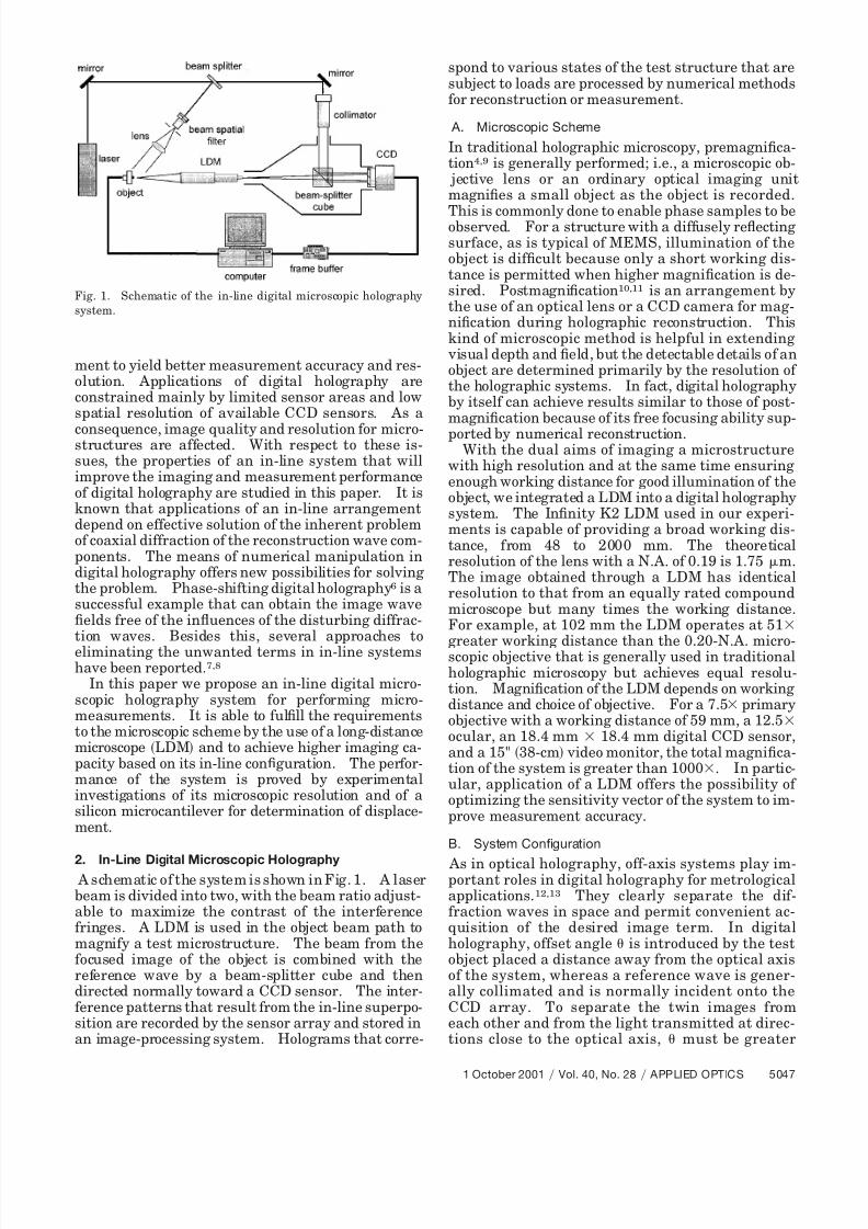
2. In-Line Digital Microscopic Holography A schematic of the system is shown in Fig. 1. A laserbeam is divided into two, with the beam ratio adjust-able to maximize the contrast of the interferencefringes. A LDM is used in the object beam path tomagnify a test microstructure. The beam from thefocused image of the object is combined with thereference wave by a beam-splitter cube and thendirected normally toward a CCD sensor. The inter-ference patterns that result from the in-line superpo-sition are recorded by the sensor array and stored inan image-processing system. Holograms that corre-
spond to various states of the test structure that aresubject to loads are processed by numerical methodsfor reconstruction or measurement.
A. Microscopic Scheme
In traditional holographic microscopy, premagni ca-tion 4,9 is generally performed; i.e., a microscopic ob- jective lens or an ordinary optical imaging unitmagni es a small object as the object is recorded.
This is commonly done to enable phase samples to beobserved. For a structure with a diffusely re ectingsurface, as is typical of MEMS, illumination of theobject is dif cult because only a short working dis-tance is permitted when higher magni cation is de-sired. Postmagni cation 10,11 is an arrangement bythe use of an optical lens or a CCD camera for mag-ni cation during holographic reconstruction. Thiskind of microscopic method is helpful in extending visual depth and eld, but the detectable details of anobject are determined primarily by the resolution of the holographic systems. In fact, digital holographyby itself can achieve results similar to those of post-magni cation because of its free focusing ability sup-ported by numerical reconstruction.
With the dual aims of imaging a microstructurewith high resolution and at the same time ensuringenough working distance for good illumination of theobject, we integrated a LDM into a digital holographysystem. The In nity K2 LDM used in our experi-ments is capable of providing a broad working dis-tance, from 48 to 2000 mm. The theoreticalresolution of the lens with a N.A. of 0.19 is 1.75 m.The image obtained through a LDM has identicalresolution to that from an equally rated compoundmicroscope but many times the working distance.For example, at 102 mm the LDM operates at 51
greater working distance than the 0.20-N.A. micro-scopic objective that is generally used in traditionalholographic microscopy but achieves equal resolu-tion. Magni cation of the LDM depends on workingdistance and choice of objective. For a 7.5 primaryobjective with a working distance of 59 mm, a 12.5ocular, an 18.4 mm 18.4 mm digital CCD sensor,and a 15" 38-cm video monitor, the total magni ca-tion of the system is greater than 1000 . In partic-ular, application of a LDM offers the possibility of optimizing the sensitivity vector of the system to im-prove measurement accuracy.
B. System Conguration
As in optical holography, off-axis systems play im-portant roles in digital holography for metrologicalapplications. 12,13 They clearly separate the dif-fraction waves in space and permit convenient ac-quisition of the desired image term. In digitalholography, offset angle is introduced by the testobject placed a distance away from the optical axisof the system, whereas a reference wave is gener-ally collimated and is normally incident onto theCCD array. To separate the twin images fromeach other and from the light transmitted at direc-tions close to the optical axis, must be greater
Fig. 1. Schematic of the in-line digital microscopic holographysystem.
1 October 2001 Vol. 40, No. 28 APPLIED OPTICS 5047

8/6/2019 ++ Pozice Obrazu v Off-Axis Hologramu
http://slidepdf.com/reader/full/-pozice-obrazu-v-off-axis-hologramu 3/6
than a minimum value min . Suppose that the ob - ject has no spatial frequency components greaterthan W . The spatial spectra of the diffractionterms of an off-axis hologram are as illustrated inFig. 2. The terms G 1 , G 2 , G 3 , and G 4 are thespectra of the direct transmitting wave, the halo
wave about the zero-order term, the real image, andthe virtual image with the center frequencies dis-placed at sin , 0 and sin , 0 , respectively.Here is the working wavelength. Evidently, G 3or G 4 can be isolated from G 2 if sin 3W .The minimum allowable offset angle is thus minsin 1 3W . Suppose that the lateral dimension of the object is LO . In the case of off-axis Fresnelholography in which the object is placed a distance D from the recording plane, the bandwidth of theobject in the hologram plane is 2 W LO D.Therefore min 3 LO 2 D for a small value. Thismeans that, besides the restriction of the maximuminterference angle max as a result of the limitedspatial resolution of CCD sensors, digital recordingof an off-axis hologram is affected by the require-ment of min . For a speci c sensor array charac-
terized by number of pixels N and pixel size N , themaximum allowable dimension of a test object at arecording distance D is
LO:off-axis D N N N 4. (1)
For the in-line con guration, however, the allow-able object size is determined solely by max . Toful ll the sampling theorem across the whole CCDchip requires the following dimensional constraint of the object:
LO:in-line D N N N . (2)
With respect to micromeasurement, imaging qualityis essential for evaluating system performance. In-asmuch as the highest spatial frequency in the recon-structed image in digital holography is de ned by N N D ,14 the space – bandwidth products of thetwo system arrangements are
SW off-axis N N N 2 D 4, (3)
SW in-line N N N 2 D . (4)
Equations 3 and 4 give a quantitative compari-son of the imaging performance of the digital holog-raphy system based on the off-axis and the in-linecon gurations. In an in-line system, less constraintis applied to the lateral size of an object, namely, theeffective eld of view. This property enables a testmicrostructure to be recorded with high magni ca-tion and resolution, both of which are important inmicromeasurement. In addition, the coaxial ar-rangement of an in-line system permits suf cient uti-lization of the limited sensor area and helps to relaxthe requirement on spatial resolution of a CCD sen-sor. Additionally, the principal and central parts of the reconstructed image area can be explored for theinformation of interest. Thus, better reconstructionand higher resolution can be realized. 15
3. Wave-Front AnalysisFigure 3 illustrates the coordinate system for wave-front analysis. Suppose that d O , d L , and D repre-sent the object distance, the image space distance,and the reconstruction distance, respectively. Forthe test microstructures, because their angular sizesare suf ciently small relative to the distances, wemay adopt the paraxial approximation in the analy-sis. If the spherical wavelet from a point source p inthe object plane can be expressed as O pO A pO
exp j pO , the wave front in the hologram plane, af-ter being modulated by the imaging system and trav-eling distance d L , has the complex amplitude
where f is the focal length of the microscopic systemand cm denotes the aperture function.
In numerical reconstruction, by omission of theconstant components, the real-image wave eld inthe image plane is
U p x1, y1 O pH
exp jk x1 x H
2 y1 y H 2
2 Dd x H d y H . (6)
O p x H , y H A pO
d O
1 j d L
exp jkd O jkd L j pO cm x A, y A exp jk x A xO
2 y A yO2
2d O
exp jk2 f
x A2 y A
2 exp jk x H x A
2 y H y A2
2d Ld x Ad y A, (5)
Fig. 2. Spatial spectra of an off-axis hologram.
5048 APPLIED OPTICS Vol. 40, No. 28 1 October 2001

8/6/2019 ++ Pozice Obrazu v Off-Axis Hologramu
http://slidepdf.com/reader/full/-pozice-obrazu-v-off-axis-hologramu 4/6
We make B A pO exp jkd O jkd L j pO j d O d Land 1 D L 1 d O 1 d L 1 f . Substituting Eq. 5into relation 6 , we obtain
We modulate the equation and neglect the limitationof the aperture size by setting cm 1 over the range
, ; the complex amplitude of the reconstructedreal-image wave eld is nally given as
According to the linear system theory 16 in Fourier
optics, diffraction analysis of an elementary sourcepoint is representative of the characteristics of theintegral output of a system. Therefore relation 8also represents the imaging and reconstruction of athree-dimensional object.
4. Experimental Investigations
A. Microcantilever Experiment
Generally, the mechanical architectures of MEMScan be assimilated into an assembly of beams, plates,or membranes xed upon a more-massive substrate
and subjected to mechanical loads such as bending,tension, and pressure. 11 Inasmuch as the studies of these basic microstructures are representative for
demonstrating the performance of the system, a mi-crobeam structure made from single-crystal silicon isemployed as a test object in our experimental inves-tigations. The microbeam is 2.4 mm long, with a
rectangular 0.43 mm 0.45 mm cross section and is
subjected to a concentrated bending force at the freetip. A diode-pumped frequency-doubled Nd:YVO 4laser 532 nm with an output power of 40 mW isused as the light source. With a working distance of 135 mm provided by the LDM, the test microbeam iswell illuminated, with an illumination angle of 45 °. The real image is reconstructed at a distance of 486 mm.
Figure 4 shows the numerically calculated inter-ference phase that corresponds to an applied force of 38 mN. Knowing the phase value for each pixel,we can solve the out-of-plane displacement induced
Fig. 3. Coordinate system for wave-front analysis.
U p x1, y1 A pO
d O
1d L D DD L
1d L
exp jkd O jkd L j O expjd O
xO2 yO
2 expj
d L D x1
2 y12
exp j 1
1 D L
Dd L d L D
xO
d O
x1
d L D
2 yO
d O
y1
d L D
2
. (8)
U p x1, y1 B expjd O
xO2 yO
2 expj D
x12 y1
2) cm x A, y A exp jk x A
2 y A2
2 D L
exp jk x A xO y A yO
d Oexp
jk2
1d L
1 D
x H 2 y H
2 exp jk x H x A
d L
x1
D
y H y A
d L
y1
Dd x H d y H d x Ad y A. (7)
1 October 2001 Vol. 40, No. 28 APPLIED OPTICS 5049

8/6/2019 ++ Pozice Obrazu v Off-Axis Hologramu
http://slidepdf.com/reader/full/-pozice-obrazu-v-off-axis-hologramu 5/6
by the bending load for each point on the cantileversurface by using the linear equation
w x, y4 cos 2 2
x, y . (9)
Figure 5 shows the experimentally determined dis-placement component w of the microcantilever sur-face.
Fresnel reconstruction of an in-line digital holo-gram results in the superposition of the image termsupon the zero-order component. Because the major-ity of the reconstruction energy is concentrated in thedirectly transmitting wave, the intensity of the zero-order term is generally much greater than those of the image waves. As is shown in Fig. 6 a , the de-
sired image of the microcantilever is completelyhidden by the bright square background. Some ef-fective methods 17 of eliminating the zero-order termin digital holography have been proposed. In ourexperiments, high-pass digital ltering with a 3 3neighborhood operation was performed on the holo-gram.
Suppose that the complex amplitudes of the objectwave and the reference wave in the hologram planeare O x H , y H and R x H , y H , respectively. Blockingthe unwanted frequency components yields a lteredhologram, which can be described by
h F x H , y H v x H , y H R* x H , y H O x H , y H
R x H , y H O * x H , y H , (10)where v x H , y H represents the residual part of thezero-order term after the lter has been applied toO x H , y H
2 R x H , y H 2 as a result of the presence
of some high-frequency components. The result af-ter the operation is shown in Fig. 6 b . A prepro-cessing procedure, which subtracts the intensity sumof the object and reference waves from the originalhologram before the ltering operation, is found to beef cient for improving the image quality. As shownin Fig. 6 c , the real image of the test object is clearlyreconstructed. The method described here is quitestraightforward. Other approaches can also be ap-plied to achieve similar or better results. Experimen-tally, the intensity distributions of the object and thereference beams can easily be obtained and can beassumed to be constant in different loading states.Therefore, three images are enough for reconstructionof the desired results with good quality. This methodis suited for dynamic applications in which it is impos-sible to take phase-shifted holograms.
B. Resolution Capability
To study the microscopic resolution of the system, weapply a standard U.S. Air Force resolution test targetas the test sample. With the same laser source andpower, the test target is well illuminated at a working
Fig. 4. Interference phase for displacement determination.
Fig. 5. Out-of-plane displacement component of the microcanti-lever.
Fig. 6. Reconstructed images of the microcantilever.
5050 APPLIED OPTICS Vol. 40, No. 28 1 October 2001

8/6/2019 ++ Pozice Obrazu v Off-Axis Hologramu
http://slidepdf.com/reader/full/-pozice-obrazu-v-off-axis-hologramu 6/6
distance of 59 mm. Holograms are taken by a Kodak4.2i CCD camera with 2048 2048 pixels of 9 m9 m size. Figure 7 shows the experimental resultsfor the real images of the target patterns recon-structed at a distance of 300 mm. Among them, thenest linewidth of 8.769 m can be clearly resolved.The results demonstrate the capability of the pro-posed system to measure microstructures with lat-eral dimensions of at least 8 m. Greater resolutioncanbe expected with further improvements in systemarrangement and noise suppression.
5. Conclusions
In conclusion, an in-line digital microscopic hologra-phy system for micromeasurement has been pro-posed. With the incorporation of a LDM, it wellful lls the requirements of imaging microstructureswith high resolution at suf cient working distancesfor good illumination. Developed on the basis of thein-line con guration, the system achieves 4 greaterimaging performance than do commonly adopted off-axis arrangements and exhibits the properties of more-ef cient utilization of the CCD sensor size andreconstructed image area. Besides performing thefunction of three-dimensional imaging of microstruc-tures, the system will be especially useful in quanti-tative displacement or shape measurement forcharacterization of MEMS. Its performance hasbeen proved with experiments to determine the dis-placement of a silicon microcantilever. The resolu-tion capability of the system has been preliminarily
investigated, and a test pattern of 8 m was clearlyresolved.
References1. A. Umeda, “Review on the importance of measurement tech-
nique in micromachine technology, ” in Microlithography and Metrology in Micromachining II , M. T. Postek and C.Friedrich, eds., Proc. SPIE 2880, 26 –38 1996 .
2. G. C. Brown and R. Pryputniewicz, “Holographic microscope
for measuring displacements of vibrating microbeams usingtime-averaged, electro-optic holography, ” Opt. Eng. 37, 1398 –1405 1998 .
3. L. A. Salbutand M. Kujawinska, “Grating microinterferometerfor local in-plane displacement strain eld analysis, ” in Inter-national Conference on Applied Optical Metrology , P. K. Ras-togi and E. Gyimesi, eds., Proc. SPIE 3407, 490 – 494 1998 .
4. G. K. Wernicke, O. Kruschke, N. Demoli, and H. Gruber, “In- vestigation of micro-opto-electro-mechanical components witha holographic microscopic interferometer, ” in Nondestructive Evaluation of Materials and Composites II , S. R. Doctor, C. A.Lebowitz, and G. Y. Baaklini, eds., Proc. SPIE 3396, 238 –2431998 .
5. U. Schnars and W. Juptner, “Direct phase determination inhologram interferometry with use of digitally recorded holo-
grams, ” J. Opt. Soc. Am. A 11, 2011 –2015 1994 .6. I. Yamaguchi and T. Zhang, “Phase-shifting digital hologra-phy, ” Opt. Lett. 22, 1268 –1270 1997 .
7. G. Pedrini, P. Froning, H. Fessler, and H. Tiziani, “In-linedigital holographic interferometry, ” Appl. Opt. 37, 6262 – 62691998 .
8. S. Lai, B. Kemper, and G. Bally, “Off-axis reconstruction of in-line holograms for twin-image elimination, ” Opt. Commun.169, 37 – 43 1999 .
9. O. Kruschke, G. K. Wernicke, T. Huth, N. Demoli, and H.Gruber, “Holographic interferometric microscope for completedisplacement determination, ” Opt. Eng. 36, 2448 –2456 1997 .
10. R. J. Pryputniewicz, “Heterodyne holography applications instudies of small components, ” Opt. Eng. 24, 849 – 854 1985 .
11. E. Bonnotte,P. Delobelle, andL. Bornier, “Two interferometric
methods for the mechanical characterization of thin lm bybulging tests. Application to single crystal of silicon, ” J. Ma-ter. Res. 12, 2234 –2248 1997 .
12. S. Seebacher, W. Osten,and W. P. Jueptner, “Measuringshapeand deformation of small objects using digital holography, ” in Laser Interferometry IX: Applications , R. J. Pryputniewicz,G. M. Brown, and W. P. Jueptner, eds., Proc. SPIE 3479,104 –115 1998 .
13. G. Pedrini, Y. L. Zou, and H. T. Tiziani, “Digital double-pulsedholographic interferometry for vibration analysis, ” J. Mod.Opt. 42, 367 –374 1995 .
14. C. Wagner, S. Seebacher, W. Osten, and W. Juptner, “Digitalrecording and numerical reconstruction of lensless Fourier ho-lograms in optical metrology, ” Appl. Opt. 38, 4812 – 48201999 .
15. L.Xu, J.Miao, and A.Asundi, “Properties of digital holographybased on in-line con guration, ” Opt. Eng. 39, 3214 –32191999 .
16. J. W. Goodman, Introduction to Fourier Optics McGraw-Hill,New York, 1996 , pp. 19 –22.
17. T. M. Kreis and W. P. Juptner, “Suppression of the dc term indigital holography, ” Opt. Eng. 36, 2357 –2360 1997 .
Fig. 7. Real images of the U.S. Air Force test target Group 5,
Elements 1 – 6 .
1 October 2001 Vol. 40, No. 28 APPLIED OPTICS 5051
Related Documents