Plastic Piping Handbook Chemtrol ® Thermoplastic Flow Solutions Chemtrol ® is a brand of

Welcome message from author
This document is posted to help you gain knowledge. Please leave a comment to let me know what you think about it! Share it to your friends and learn new things together.
Transcript

Plastic Piping Handbook
Chem
trol
® T
herm
opla
stic
Flo
w S
olut
ions
Every solution begins with a good idea.
We’ve got ideas that flow
directly to solutions for
your industrial piping
applications. Ideas that
make your installations
easier and more cost-
effective. Ideas that work,
and ideas that last. Our
ideas are strengthened by
a sound foundation for
growth and a solid
commitment to service.
For ideas that fit your
flow-control applications,
call on us. We’re Chemtrol,
a product line committed
to innovation, growth,
and superiority in
thermoplastics—
ideas whose time
has come.
CH-HB-0914
NIBCO INC.World Headquarters1516 Middlebury StreetElkhart, IN 46516-4740USA
Phone: 800.343.5455Fax: 800.541.3841
Technical Service: Phone: 888.446.4226
International Office: Phone: +1.574.295.3327Fax: +1.574.295.3455
www.chemtrol.com
Corzan® is a registered trademark of The Lubrizol Corporation.Tru-Bloc® is a registered trademark of NIBCO INC.Chem-Pure® is a registered trademark of NIBCO INC.Chemcock® is a registered trademark of NIBCO INC.Kynar® is a registered trademark of Arkema Inc.
Ideas that flow.
- Plastic Piping Handbook
Chemtrol® is a brand of


www.chemtrol.com
NIBCO INC. World Headquarters 1516 Middlebury St. • Elkhart, IN 46516-4740 • USA
Ph: 1.800.343.54553
plastic piping handbook“To the best of our knowledge the information contained in this publication is accurate; however, we do not assume any liability whatsoever for the accuracy or completeness of such information. Moreover, there is a need to reduce human exposure to many materials to the lowest practical limits in view of possible long-term adverse effects. The extent that any hazards may have been mentioned in this publication, we neither suggest nor guarantee that such hazards are the only ones which exist. Final determination of the suitability of any information or product for the use contemplated by any user, the manner of that use and whether there is any infringement of patents or other third-party intellectual property is the sole responsibility of the user. We recommend that anyone intending to rely on any recommendation or to use any equipment, processing technique or material mentioned in this publication should satisfy himself as to such suitability and that he can meet all applicable safety and health standards. We strongly recommend that users seek and adhere to the manufacturer’s or supplier’s current instructions for handling each material they use.”
Ideasthat flow.

NIBCO INC. World Headquarters 1516 Middlebury St. • Elkhart, IN 46516-4740 • USA
Ph: 1.800.343.5455
www.chemtrol.com
4
chemtrol® plastic piping handbooktable of contents
page introduction ................................................................................6 Foreward ...........................................................................7 The Advantages of Plastic Piping ....................................8 Why Chemtrol® Piping Components are Preferred .....................................................................9 Materials ........................................................................10 Chemical Resistance .......................................................12 Standards .........................................................................12 Physical Properties ..........................................................15 Product Line .....................................................................16 pressure Ratings of chemtrol products ............................22 Pipes and Fittings ...........................................................23 Valve, Unions and Flanges .............................................24 Temperature Ratings of Chemtrol Products ...................25 Products in Vacuum or Collapse in Loading Situations ..26 pressure losses in a piping system ..................................27 Piping Calculations .........................................................28 Valve Calculations ..........................................................28 Flow Capacity & Friction Loss for Sch. 40 Pipe .............29 Flow Capacity & Friction Loss for Sch. 80 Pipe .............30 Hydraulic Shock ..............................................................31 Shock Surge Wave .........................................................32 Expansion & thermal contraction of plastic pipe ..........34 Calculating Dimensional Changes .................................34 Calculating Stress ...........................................................36 Managing Expansion/Contraction in System Design ....38 Minimum Cold Bending Radius ......................................40 Pipe Support Spacing .....................................................41 chemical Resistance guide .................................................43 schedule 80 pipe & Fitting dimensions ............................77 Valves .......................................................................................82 PVC/CPVC Tru-Bloc® Ball Valves ....................................83 PVC/CPVC Bleach Ball Valves ........................................85 PP True Union Ball Valves ..............................................86 PVDF True Union Ball Valves ...........................................88 PVC/CPVC 3-Way Ball Valves .........................................90 PVC Compact Economy Ball Valves ................................92 PVC/CPVC Butterfly Valves ..............................................93 PVC/CPVC Ball Check, Foot and Vent Valves .................96

www.chemtrol.com
NIBCO INC. World Headquarters 1516 Middlebury St. • Elkhart, IN 46516-4740 • USA
Ph: 1.800.343.54555
chemtrol® plastic piping handbooktable of contents
page
PP/PVDF Ball Check Valves .............................................98 PVC Angle and Y-Pattern Valves ..................................100 PVC Chemcock and Calibrated Needle Valves .............102 Valve Accessories ..........................................................104 Ball Valve Actuation ......................................................108 Actuator Mounting Data................................................109 Valve Installation ...........................................................117 Valve Maintenance ........................................................120 pVc Fittings ...........................................................................123 cpVc Fittings .........................................................................145 socket Fusion Equipment ....................................................162 polypropylene pipe & Fittings ............................................164 pVdF pipe & Fittings ............................................................178 installation of pressure piping ..........................................191 Storage .........................................................................191 Handling ........................................................................191 Joining Methods ...........................................................192 Solvent Cement Joining for PVC/CPVC ........................194 Heat Fusion Joining for PP/PVDF ..................................201 Joining Mechanics for Hand-Held Heat-Tools .............202 Features of Bench-Mount Joining Machines ..............205 Joining Mechanics for Bench-Mount Machines .........208 Flanged Joints ..............................................................211 Repairing Joints ............................................................213 Threading Instructions for Plastic Pipe ........................216 Effect of Ultraviolet Radiation .......................................218 General Underground Installation Procedures .............219 Reference data .....................................................................225 Metric Equivalent Charts ..............................................225 Conversion Factors .......................................................226 Specific Gravity of Liquids ............................................227 Drill Sizes for Pipe Taps ................................................228 Useful Formulas ............................................................229 Symbols for Pipe Fittings Used in Drafting ..................231 Abbreviations ................................................................234 Glossary of Terms .........................................................235

NIBCO INC. World Headquarters 1516 Middlebury St. • Elkhart, IN 46516-4740 • USA
Ph: 1.800.343.5455
www.chemtrol.com
6
chemtrol products — a multitude ofapplications and end uses
Heating & Cooling
Mining IndustryChemical Processing
Nuclear Industry
High Purity Applications
Wastewater Industry
Petrochemical
intRodUction

www.chemtrol.com
NIBCO INC. World Headquarters 1516 Middlebury St. • Elkhart, IN 46516-4740 • USA
Ph: 1.800.343.54557
FoREwaRdGrowth in the use of plastic piping has been nothing less than spec-tacular. In 1947 sales of plastic piping in the United States amounted to less than $500,000; however, seven decades later sales have exceeded five billion dollars and show no signs of slowing down.
Plastic piping is employed for chemical and food processing, for nat-ural gas distribution and supply, for shipboard installations, for municipal water treatment, for industrial and residential plumbing, and a host of other applications.
Despite the growing popularity of plastic piping, reliable, up-to-date and comprehensive information sometimes is difficult to obtain, and there is a genuine need for a handy reference expressly pertinent to the industry. This Chemtrol Plastic Piping Handbook represents an earnest effort to meet that need.
It contains summaries of the chemical and physical properties of frequently used plastic piping materials, item listings of Chemtrol® fittings and valves, make-up dimensions, recommended methods of joining plastic products, tips on fabrication and installation, and selected tables, graphs and charts of technical data required for practically every piping job.
intRodUction
NIBCO INC. World Headquarters 1516 Middlebury St. • Elkhart, IN 46516-4740 • USA
Ph: 1.800.343.5455
www.chemtrol.com
8
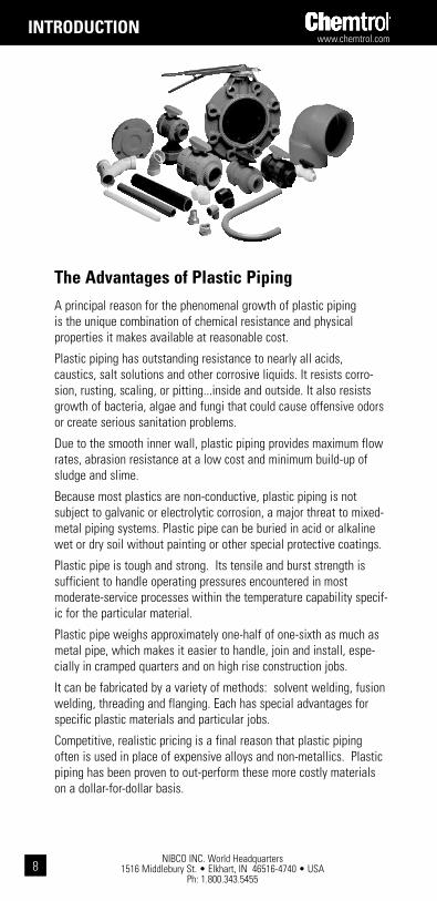
the advantages of plastic pipingA principal reason for the phenomenal growth of plastic piping is the unique combination of chemical resistance and physical properties it makes available at reasonable cost.
Plastic piping has outstanding resistance to nearly all acids, caustics, salt solutions and other corrosive liquids. It resists corro-sion, rusting, scaling, or pitting...inside and outside. It also resists growth of bacteria, algae and fungi that could cause offensive odors or create serious sanitation problems.
Due to the smooth inner wall, plastic piping provides maximum flow rates, abrasion resistance at a low cost and minimum build-up of sludge and slime.
Because most plastics are non-conductive, plastic piping is not subject to galvanic or electrolytic corrosion, a major threat to mixed-metal piping systems. Plastic pipe can be buried in acid or alkaline wet or dry soil without painting or other special protective coatings.
Plastic pipe is tough and strong. Its tensile and burst strength is sufficient to handle operating pressures encountered in most moderate-service processes within the temperature capability specif-ic for the particular material.
Plastic pipe weighs approximately one-half of one-sixth as much as metal pipe, which makes it easier to handle, join and install, espe-cially in cramped quarters and on high rise construction jobs.
It can be fabricated by a variety of methods: solvent welding, fusion welding, threading and flanging. Each has special advantages for specific plastic materials and particular jobs.
Competitive, realistic pricing is a final reason that plastic piping often is used in place of expensive alloys and non-metallics. Plastic piping has been proven to out-perform these more costly materials on a dollar-for-dollar basis.
intRodUction

www.chemtrol.com
NIBCO INC. World Headquarters 1516 Middlebury St. • Elkhart, IN 46516-4740 • USA
Ph: 1.800.343.54559
Technical service and sales support.
Our technical specialists are some of the best in the business. As part of your team, they provide expert advice, solve problems, and assist you every step of the way.
Our distributors, sales professionals, and service representatives offer ideas, answer questions, and put their knowledge to work for you.
Education and training.
We help you learn about the benefits of thermoplastics through excellent programs: classes and seminars specific to your industry, presented at our manufacturing facility, or product and application- specific seminars conducted in the field. Our high-quality product and technical manuals are available on request, and a full listing of Chemtrol products is provided on our web site, www.chemtrol.com
Innovative technology.
Great ideas flow from Chemtrol in PVC, CPVC, PP, and PVDF products for a wide range of flow-control applications.
why chemtrol piping components are preferred
Proven dependability.
Chemtrol flow-control products are unsurpassed in performance and longevity. With 60 years of experience in industrial thermoplastics, Chemtrol offers dependable products that work in the most demanding environments.
intRodUction

NIBCO INC. World Headquarters 1516 Middlebury St. • Elkhart, IN 46516-4740 • USA
Ph: 1.800.343.5455
www.chemtrol.com
10
Kynar® is a registered trademark of Arkema Inc.Corzan® is a registered trademark of The Lubrizol Corporation.
pVc(polyvinyl chloride) pVc conforming to astM d1784, classification 12454, for-merly designated type i, grade 1, is the most frequently specified of all thermoplastic piping materials. It has been used successfully for more than 55 years in such diverse areas as chemical processing, industrial plating, chemical drainage, fresh and wastewater treat-ment, chilled and tower cooling water, deionized water manufacture and distribution, and irrigation sprinkler systems. PVC is characterized by high physical properties and resistance to chemical attack by strong acids and other oxidizers, alkalis, salt solutions, some organic chemical solutions, and many other chemicals. However, it is attacked by non-ionic surfac-tants, some vegetable oils (e.g., peanut), and many organic chemicals such as polar sol-vents (e.g., ketones), aromatics (i.e., benzene ring structure), and chlorinated hydrocarbons. The maximum service temperature of PVC is 140°F. With a design stress of 2,000 psi at 73°F, the long-term hydrostatic strength of PVC is as high as any of the major thermoplas-tic materials being used for solid piping systems. PVC is joined by solvent cementing, threading, or flanging.
cpVc (corzan®)(chlorinated polyvinyl chloride) cpVc conforming to astM d1784, classification 23447, is a resin created by the post-chlorination of a PVC polymer. The material’s resis-tance to chemical attack is almost identical to that of PVC. And the physical properties of CPVC are very similar to those of PVC at 73°F, but the additional chlorine in the CPVC polymer extends its maximum service temperature to 210°F. For example, the design stress for CPVC is 2,000 psi at 73°F, identical to that of PVC. But its strength is only reduced to 500 psi at 180°F, as compared to 440 psi for PVC at 140°F. For more than 35 years, CPVC has proven to be an excellent material for hot corrosive liquids, hot and cold water distribu-tion, and similar applications above the useful temperature range for PVC. CPVC may even be chosen over PVC in the 110°F to 140°F temperature range because its higher strength-at-temperature, requiring less frequent piping supports, can translate to a more favorable overall installed cost than PVC. CPVC is joined by solvent cementing, threading, or flanging.
pVdF (kynar®)(polyvinylidene Fluoride) pVdF homopolymer conforming to astM d3222, type i, grade 2, is a tough, abrasion-resistant fluorocarbon material that has a design stress of 1,360 psi at 73°F and a maximum service temperature of 280°F. It has versatile chemical resistance to salts, strong acids, dilute bases, and many organic solvents, such as the aromatics (i.e., benzene ring structure), the aliphatics (i.e., paraffin, olefin, and acetylene hydrocarbons), and the chlorinated groups. And PVDF is ideally suited for handling wet or dry chlorine, bromine, and other halogens. However strong bases and some organic chemicals such as polar solvents (e.g., ketones) and esters attack it. No other solid ther-moplastic piping material can approach the combined strength, working temperature, and chemical resistance characteristics of PVDF. It is joined by the thermo-sealing socket fusion process, threading, or flanging.
PVDF, absent of any color pigment, is transparent to ultraviolet light. So while PVDF is one of the few plastic materials that is not degraded by UV radiation, exposure of the fluid medium inside a piping system to direct sunlight can frequently adversely affect its stabil-ity. Therefore, all PVDF piping components that Chemtrol produces for general chemical service, contain an FDA-approved red pigment to mask the penetration of UV rays.
Natural Kynar® PVDF Type I (polymerized in emulsion) homopolymer is notably free of metallic ions and foreign organic compounds. And since the resin does not require processing or other external additives to aid manufacturing or long-term stability, the hard-polish surface of components will remain intact, so that piping systems will not release particulate to the fluid medium. Further, there will be no surface micropores to encourage biological growth. Natural Kynar® systems are intended for ultra high pure water and chemical services, such as electronics, pharmaceuticals, and processed foods and beverages.
intRodUction

www.chemtrol.com
NIBCO INC. World Headquarters 1516 Middlebury St. • Elkhart, IN 46516-4740 • USA
Ph: 1.800.343.545511
pp(polypropylene) pp as specified by astM d4101, is a member of the polyolefin family of pure hydrocarbon plastics. Although PP has half the strength of PVC and CPVC, with a design stress of 1,000 psi at 73°F, it may have the most versatile chemical resis-tance of the thermoplastic materials identified as the sentinels of industrial piping. Consider the fact that there are no known solvents for PP. As a result, it has been the material of choice for drainage of mixed industrial chemicals for over 40 years. As pres-sure piping, PP has no peers for concentrated acetic acid or hydroxides. It is also suitable for milder solutions of most acids, alkalis, salts, and many organic chemicals, including solvents. The nemeses for PP are strong oxidizers, such as the hypochlorites and higher concentrations of sulfuric, nitric, and hydrofluoric acids. They are Environmental Stress Cracking (ESC) agents for PP, meaning that time-to-failure is a function of the combined variables of concentration and temperature of the fluid and stress. Although PP is not recommended for some organic chemicals, such as polar and chlorinated solvents and the aromatics, the concern is permeation through rather than catastrophic damage of the molecular chain.
Black PP used in Chemtrol products is formulated with a minimum 2.5% carbon black. The plastic pipe industry recognizes PP formulated with this level of carbon black as suitable for long-term outdoor service.
Chem-Pure® Natural PP utilized to produce Chemtrol® piping products was selected because of its extremely low content of metals, organic compounds other than naturally pure propylene, and free ions. No pigments or other adulterants (natural) are added to the plastic resin. Chem-Pure® systems are intended for high purity chemicals or DI water. Chem-Pure systems are intended as an economic alternative to the ultra high purity PVDF systems typically found in the highly sophisticated electronic semi-conduc-tor industry.
FkM(Fluoroelastomer) FkM is compatible with a broad spectrum of chemicals. Because of this extensive chemical compatibility, spanning wide ranges of concentration and temperature, FKM has gained wide acceptance as a material of construction for valve o-rings and seats. These fluoroelastomers can be used in most applications involving mineral acids (with the exception of HCl), salt solutions, chlorinated hydrocarbons, and petroleum oils. FKM is not recommended for most strong alkali solutions.
EpdM(Ethylene-propylene-diene monomer) EpdM is a terpolymer elastomer that has good abrasion and tear resistance and offers excellent chemical resistance to a variety of salt, acidic, and organic chemical solutions. It is the best material for most alkali solutions and hydrochloric acid, but is not recommended for applications involving petroleum oils or most strong acids.
ptFE(polytetrafluoroethylene) ptFE has outstanding resistance to chemical attack by most chemicals and solvents. PTFE has a temperature rating of -200°F to +500°F. It is a self-lubricating material used as a seat and/or bearing material in most Chemtrol® valves.
intRodUction

NIBCO INC. World Headquarters 1516 Middlebury St. • Elkhart, IN 46516-4740 • USA
Ph: 1.800.343.5455
www.chemtrol.com
12
While thermoplastic piping systems are useful in general water service because they are light-weight, easy to install, and cost-effective, they excel in corrosive environments, such as water and wastewater treatment, food and pharmaceuticals, chemical processing, mining, power plants, oil refineries and more. Choosing the proper material for corrosive fluids can be handled by consulting NIBCO’s chemical resistance guide and understanding the effect that temperature will have upon plastic materials’ strength.
Chemical resistance is the ability for a particular plastic material to maintain properties in contact with a chemical. To ensure comprehensive chemical compatibility, a piping system must take into consideration the chemical resistance of all system components, including, but not limited to, plastic components, solvent cements or thread pastes (if applicable), elastomeric seals, all valve components and lubricants. Testing under field conditions may be the best way to ensure selected materials will work in a particular application.
chemical Resistance
intRodUction
Many commercial, industrial, and governmental standards or specifications are available to assist the design engineer in specifying plastic piping systems. Standards most frequently referred to and most commonly called out in plastic piping specifications are ASTM Standards. These standards also often form the basis of other standards in existence. Below is a list and description of those standards most typically applied to industrial plastic piping.
astM d1784(american society for testing and Materials)This specification covers rigid PVC and CPVC compounds intended for general purpose use in extruded or molded formincluding pressure piping applications and nonpressure piping applicationscomposed of poly(vinyl chloride), chlorinated poly(vinyl chloride), or vinyl chloride copolymers containing at least 80% vinyl chloride, and the necessary compounding ingredients.
astM d1785 and F441These standards cover the specification and quality of Schedule 40, 80, and 120 PVC (D1785) and CPVC (F441) pressure pipe. Outlined in these standards are dimensional specifications, burst, sustained, and maximum operating pressure requirements and test procedures for determining pipe quality with respect to workmanship and materials.
astM d2466This standard covers Schedule 40 PVC threaded and socket pressure fittings. Stipulated in the standard are thread and socket specifications, by lengths, wall thickness, burst, material, quality, and identification requirements.
astM d2467 and F439These standards cover Schedule 80 PVC (D2467) and CPVC (F439) Socket Type and Threaded Pressure Fittings. Dimensions, burst strength, resin compound stipulation, and scheme of product identification requirements are specified.
astM d2564 and F493These standards set forth requirements for PVC (D2564) and CPVC (F493) Solvent Cement. The specification identifies the resin compound to be used and stipulates minimum resin content, solution viscosities, and physical performance qualities.
standards

www.chemtrol.com
NIBCO INC. World Headquarters 1516 Middlebury St. • Elkhart, IN 46516-4740 • USA
Ph: 1.800.343.545513
intRodUction
astM F656This specification covers requirements for primers for use with poly (vinyl chloride) (PVC) pipe and fittings that are to be joined by PVC solvent cements meeting the requirements of Specification.
astM F1970This specification covers special engineered fittings or appurtenances for use in PVC or CPVC systems. Flanges, unions, and valves not included in the scope of other ASTM specifications are specifically referenced. Minimum requirements are identified for testing materials, dimensions, marking, and in-plant quality control.
astM F1498This specification adapts the General Purpose American Pipe Thread Specification, ASME B1.20.1, to taper pipe threads for use on plastic pipe and fittings with machined or molded threads. The standard covers dimensions and gaging of plastic tapered National Pipe Threads (NPT) for leak-tight joints, and it is now referenced in all ASTM Standards for plastic piping products.
astM d2855This standard describes the procedure for making joints with PVC pipe and fittings by means of solvent cementing.
astM d4101 (Formerly d2146)This specification covers polypropylene materials suitable for injection molding and extrusion. Polymers consist of homopolymer, copolymers, and elastomer compounded with or without the addition of impact modifiers (ethylene-propylene rubber, polyisobutylene rubber, and butyl rubber), colorants, stabilizers, lubricants, or reinforcements.
astM d1599This standard covers the test method for establishing the short-term hydraulic failure pressure of thermoplastic pipe, tubing, and fitting under specific temperature, time, and method of loading conditions. These test techniques are normally used for quality control.
astM d1598This test method covers the determination of the time-to-failure of both thermoplastic and reinforced thermosetting/resin pipe under constant internal pressure.
astM d2837This standard describes the procedure for obtaining the Hydrostatic Design Basis for all known thermoplastic pipe materials and for any practical temperature and medium. This was achieved by evaluating stress rupture data, taken from tests conforming to ASTM D1598, for the subject material and involved specified treatment and analysis of data.
astM d2657This standard covers the procedure for heat-fusion bonding of polyolefin materials.
astM d3222This standard covers the polymerization method and physical properties of PVDF (polyvinylidene fluoride) Fluoroplastic Materials for molding and extrusion.
Organizations other than ASTM issue standards that are commonly encountered in industrial thermoplastic piping design. The most common standards are described below.

NIBCO INC. World Headquarters 1516 Middlebury St. • Elkhart, IN 46516-4740 • USA
Ph: 1.800.343.5455
www.chemtrol.com
14
asME b1.20.1 (was b2.1)This specification details the dimensions and tolerance for tapered pipe threads. This standard is referenced in the ASTM standards for threaded fittings mentioned above. See Reference Data for details.
asME b16.5This specification sets forth standards for bolt holes, bolt circles, and overall dimensions for steel 150# flanges. See Reference Data for details.
nsF/ansi 14The physical, performance, and health effects requirements in this Standard apply to thermoplastic and thermoset plastic piping system components, including but not limited to pipes, fittings, valves, joining materials, gaskets, and appurtenances. The established physical, performance, and health effects requirements also apply to materials (resin or blended compounds) and ingredients used to manufacture plastic piping system components. This Standard provides definitions and requirements for materials, ingredients, products, quality assurance, marking, and record keeping.
Fittings and valves made from copper alloys containing more than 15% zinc by weight shall be resistant to dezincification and stress corrosion cracking (SCC) and shall meet the test requirements of this standard.nsF/ansi 61This Standard establishes minimum health effects requirements for the chemical contaminants and impurities that are indirectly imparted to drinking water from products, components, and materials used in drinking water systems. This Standard does not establish performance, taste and odor, or microbial growth support requirements for drinking water system products, components, or materials.
This Standard is intended to cover specific materials or products that come into contact with: drinking water, drinking water treatment chemicals, or both. The focus of the Standard is evaluation of contaminants or impurities imparted indirectly to drinking water. The products and materials covered include, but are not limited to, process media (e.g., carbon, sand), protective materials (e.g., coatings, linings, liners), joining and sealing materials (e.g., solvent cements, welding materials, gaskets), pipes and related products (e.g., pipes, tanks, fittings), mechanical devices used in treatment/transmission/distribution systems (e.g., valves, chlorinators, separation membranes, point-of-entry drinking water treatment systems), and mechanical plumbing devices (e.g., faucets, endpoint control valves).
technical serviceTechnical assistance regarding standards, applications, product performance, design, and installation tips is available from Technical Services Technical Information Hotline: (888) 446-4226 phone; (888) 336-4226 fax.
intRodUction

www.chemtrol.com
NIBCO INC. World Headquarters 1516 Middlebury St. • Elkhart, IN 46516-4740 • USA
Ph: 1.800.343.545515
Material ASTM Test PVC CPVC Methods Properties 12454-B 23447-B PVDF Polypropylene
General D792 Specific Gravity 1.38 1.50 1.76 .905 D570 Water Absorption .05 .05 .04 .02 % 24 Hrs. @ 73° F
Mechanical D638 Tensile Strength 7,300 7,200 6,000 4,600 psi @ 73° F
D638 Modulus of 4.2 3.7 2.1 2.0 Elasticity in Tension psi @ 73° F x 105
D790 Flexural Strength psi 14,500 15,600 9,700 7,000
D256 Izod Impact Strength 1.1 2.0 3.8 .8 @ 73° F (Notched)
Thermal D696 Coefficient of 3.0 3.8 7.9 5.0 Thermal Expansion in/in/° F x 10–5
C177 Thermal 1.2 .95 .79 1.2 Conductivity BTU/HR/Sq. Ft./° F/in
D648 Heat Distortion NA NA 284 195 Temp. ° F @ 66 psi
D648 Heat Distortion 163 212 194 140 Temp. ° F @ 264 psi
Resistance to 140 210 280 180 Heat ° F at Continuous Drainage
Flammability D2863 Limiting Oxygen 43 60 44 17 Index (%) E84 Flame Spread (%) < 25 < 25 < 25 NA E84 Smoke Generation > 250 < 250 < 50 > 450
Underwriters 94V-O 94V-O 94V-O 94HB Lab Rating (Sub. 94)
physical properties of thermoplastic piping Materials
intRodUction

NIBCO INC. World Headquarters 1516 Middlebury St. • Elkhart, IN 46516-4740 • USA
Ph: 1.800.343.5455
www.chemtrol.com
16
Polyvinyl Chloride (PVC)
Typical Applications Chemical processing, industrial plating, chilled water distribution, chemical drainage, and irrigation systems
Joining Methods Solvent cementing, threading, or flanging
Max. Service Temperature 140° F/60° C
Fittings Schedule 80 Socket – 1/4" through 12"Threaded – 1/4" through 4"
Valves Tru-Bloc®/True Union ball valves
1/2" through 6" socket, threaded, and flanged ends
Tru-Bloc®/ True Union ball check valves
1/2" through 4" with socket, threaded, or flanged ends
Butterfly valves 2" through 10" with EPDM seals4" and 6" with EPDM or FKM liner
3-Way valves True Union 3-way/3-position or 3-way/2-position; 1/2" through 2" with socket or threaded ends
Specialty valves Angle and Y-Pattern: 1/4" through 1" threadedNeedle and Chemcock®: 1/4" threaded
Pipe
intRodUction
www.chemtrol.com
NIBCO INC. World Headquarters 1516 Middlebury St. • Elkhart, IN 46516-4740 • USA
Ph: 1.800.343.545517
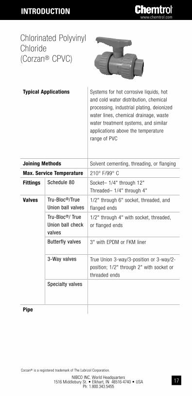
Typical Applications Systems for hot corrosive liquids, hot and cold water distribution, chemical processing, industrial plating, deionized water lines, chemical drainage, waste water treatment systems, and similar applications above the temperature range of PVC
Joining Methods Solvent cementing, threading, or flanging
Max. Service Temperature 210° F/99° C
Fittings Schedule 80 Socket– 1/4" through 12"Threaded– 1/4" through 4"
Valves Tru-Bloc®/True Union ball valves
1/2" through 6" socket, threaded, and flanged ends
Tru-Bloc®/ True Union ball check valves
1/2" through 4" with socket, threaded, or flanged ends
Butterfly valves 3" with EPDM or FKM liner
3-Way valves True Union 3-way/3-position or 3-way/2-position; 1/2" through 2" with socket or threaded ends
Specialty valves
Pipe
Chlorinated Polyvinyl Chloride(Corzan® CPVC)
Corzan® is a registered trademark of The Lubrizol Corporation.
intRodUction

NIBCO INC. World Headquarters 1516 Middlebury St. • Elkhart, IN 46516-4740 • USA
Ph: 1.800.343.5455
www.chemtrol.com
18
Typical Applications black polypropylene:Clean chemical processes, hot corrosive liquids, industrial plating, waste treatment systems
natural polypropylene:Deionized water systems, clean chemical processes, pharmaceutical operations, food processing
Joining Methods Socket heat fusion, threading, or flanging
Max. Service Temperature 180° F/82° C
Fittings Schedule 80 IPS socket ends – 1/2" through 6"Threaded – 1/2" through 4"
IPS socket ends – 1/2" through 4" Threaded – 1/2" through 4"
Valves Tru-Bloc®/True Union ball valves
1/2" through 4" with socket, threaded, or flanged ends
1/2" through 4" with socket or threaded ends
Tru-Bloc®/ True Union ball check valves
1/2" through 2" with socket, threaded, or flanged ends
1/2" through 2" with socket or threaded ends
Pipe Schedule 40 and 80 wall thicknesses
Polypropylene (PP)
intRodUction
www.chemtrol.com
NIBCO INC. World Headquarters 1516 Middlebury St. • Elkhart, IN 46516-4740 • USA
Ph: 1.800.343.545519
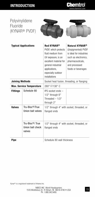
Typical Applications Red kYnaR® PVDF, which protects fluid medium from UV exposure, is an excellent material for general industrial applications, especially outdoor installations
natural kYnaR® (Unpigmented) PVDF is ideal for industries such as electronics, pharmaceuticals, and processed foods or beverages
Joining Methods Socket heat fusion, threading, or flanging
Max. Service Temperature 280° F/138° C
Fittings Schedule 80 IPS socket ends – 1/2" through 6"Threaded – 1/2" through 2"
Valves Tru-Bloc®/True Union ball valves
1/2" through 4" with socket, threaded, or flanged ends
Tru-Bloc®/ True Union ball check valves
1/2" through 4" with socket, threaded, or flanged ends
Pipe Schedule 80 wall thickness
Polyvinylidene Fluoride (KYNAR® PVDF)
Kynar® is a registered trademark of Arkema Inc.
intRodUction

NIBCO INC. World Headquarters 1516 Middlebury St. • Elkhart, IN 46516-4740 • USA
Ph: 1.800.343.5455
www.chemtrol.com
20
true Union ball ValvesThe True Union feature, a Chemtrol introduction, an exclusive Chemtrol introduction, so revolutionized the industrial plastic valve industry that it has become the standard followed by all major manufacturers. The purpose of the design is to permit the valve cartridge, i.e., the body containing all operational components, to be easily lifted from the piping system for servicing/replacement when the union nuts are backed off. Easy repair/replacement, interchangeability, distribution availability, technical service, and reliable quality are the synergistic rationale many plants and original equipment manufacturers have embraced while standardizing on Chemtrol® True Union Ball and Check Valves.
The laying length of the body and the heavy-duty modified-acme threads in the union connections to the body have not changed in the four distinct models’ 40-year history of the valve. This permits fouled valve replacement with a new body cartridge, which will fit the old union nuts. No change in piping length is required.
The distinctive orange handle indicates “open/close” and direction of flow at a distance. And molded-in arrows on top of the handle dictate rotational direction to personnel for easy operation within 90° stops. For applications requiring handle removal, the D-ring stem flats indicate "open/close" and a molded-in arrow on top of the stem indicates flow direction.
As a result of continuous testing and improvements since the inception of the True Union Ball Valve, three distinct model changes have occurred. The original True Union Model A design had a seat-carrier that slid into the smooth bore of the valve body, held in place by the external nut and end connector. Tightening the external nut adjusted the compression of the PTFE seat onto the ball.
The first major evolution to the True Union Ball Valve, Model B, introduced the Tru-Bloc concept, a functional safety feature. With this design a separate threaded retainer locked the seat-carrier into the body and prevented the seat-carrier from being extruded out of the valve body when the external nut was removed. This change is intended to prevent pressure on the other side of the valve from ejecting the internal components and fluid medium out of the open valve end and to further prevent possible injury to persons or property.
The Model C seat-carrier design was modified to include an external thread which mated into the valve body threads, eliminating the separate retainer. This modification also eliminated the adjustment of the seat-carrier by the external nut and end connector, resulting in a sealing envelope that was independent of external forces. An energized O-ring was added under the PTFE seat that provided automatic adjustment to compensate for seat wear. This design modification continued the Tru-Bloc feature, preventing the seat carrier from being extruded out of the valve body when the external valve nut was removed.
Manufactured in PVC and CPVC through 2", the current Model D ball valve’s seat-carrier internal threads and the external union nut threads were strengthened to provide an increased pressure rating of 250 psi at 73°F and improved the pressure ratings at higher temperatures. The end connector design was modified to provide wrench flats. The union nut OD was changed to provide improved gripping for strap wrenches. The Model D design continued the sealing envelope that was independent of external forces with an energized O-ring under the PTFE seat that provided automatic adjustment to compensate for seat wear. The Tru-Bloc® feature was also retained.
the Evolution of chemtrol® ball Valves
intRodUction
www.chemtrol.com
NIBCO INC. World Headquarters 1516 Middlebury St. • Elkhart, IN 46516-4740 • USA
Ph: 1.800.343.545521
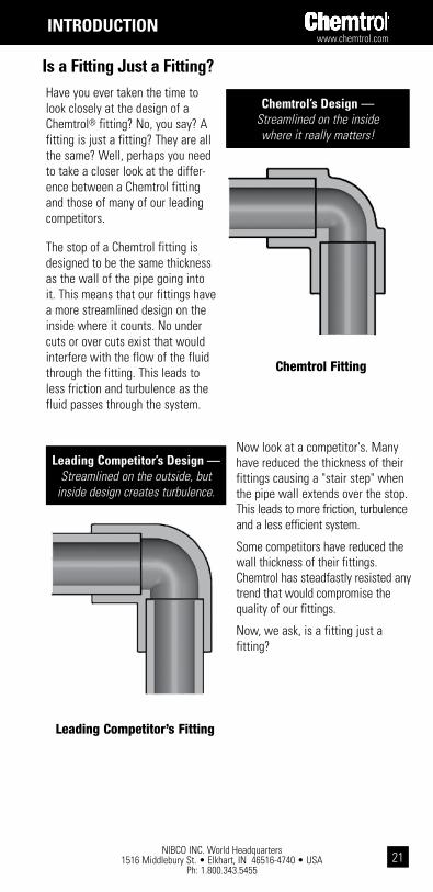
Now look at a competitor's. Many have reduced the thickness of their fittings causing a "stair step" when the pipe wall extends over the stop. This leads to more friction, turbulence and a less efficient system.
Some competitors have reduced the wall thickness of their fittings. Chemtrol has steadfastly resisted any trend that would compromise the quality of our fittings.
Now, we ask, is a fitting just a fitting?
is a Fitting Just a Fitting?
Chemtrol Fitting
Leading Competitor’s Fitting
chemtrol’s design — Streamlined on the inside where it really matters!
leading competitor’s design — Streamlined on the outside, but
inside design creates turbulence.
Have you ever taken the time to look closely at the design of a Chemtrol® fitting? No, you say? A fitting is just a fitting? They are all the same? Well, perhaps you need to take a closer look at the differ-ence between a Chemtrol fitting and those of many of our leading competitors.
The stop of a Chemtrol fitting is designed to be the same thickness as the wall of the pipe going into it. This means that our fittings have a more streamlined design on the inside where it counts. No under cuts or over cuts exist that would interfere with the flow of the fluid through the fitting. This leads to less friction and turbulence as the fluid passes through the system.
intRodUction

NIBCO INC. World Headquarters 1516 Middlebury St. • Elkhart, IN 46516-4740 • USA
Ph: 1.800.343.5455
www.chemtrol.com
22
The pressure carrying capability of any pipe at a given temperature is a function of the material strength from which the pipe is made and the geometry of the pipe as defined by its diameter and wall thickness. The following expression, commonly known as the ISO equation, is used in thermoplastic pipe specifications to relate these factors:
P = 2S / (Do/t –1)
where: P = maximum pressure rating, psi S = maximum hydraulic design stress (max. working strength), psi Do = average outside pipe diameter, in. t = minimum wall thickness, in.
The allowable design stress, which is the tensile stress in the hoop direction of the pipe, is derived for each material in accordance with ASTM D2837, Standard Test Method for Obtaining Hydrostatic Design Basis for Thermoplastic Pipe Materials, at 73° F. The pressure ratings below were calculated from the basic Hydraulic Design Stress for each of the materials.
pREssURE Ratings
pressure Ratings of chemtrol products

www.chemtrol.com
NIBCO INC. World Headquarters 1516 Middlebury St. • Elkhart, IN 46516-4740 • USA
Ph: 1.800.343.545523
Maximum non-shock operating pressure (psi) at 73° F1
Nom. Pipe Size
Schedule 40 PVC & CPVC
Schedule 80 PVC & CPVC
Schedule 80 Polypropylene Schedule 80 PVDF
Socket End
Socket End
Threaded End
Thermo-Seal Joint
Threaded End3
Thermo-Seal Joint
Threaded End
1/2 600 850 420 410 20 580 290
3/4 480 690 340 330 20 470 230
1 450 630 320 310 20 430 210
1 1/4 370 520 260 260 20 — —
1 1/2 330 470 240 230 20 326 160
2 280 400 200 200 20 270 140
2 1/2 300 420 210 — — — —
3 260 370 190 190 20 250 N.R.
4 220 320 160 160 20 220 N.R
6 180 280 N.R. 140 N.R. 190 N.R.
8 160 2502 N.R. — — — —
10 140 230 N.R. — — — —
12 130 230 N.R. — — — —
1 For more severe service, an additional correction factor may be required.2 8" CPVC Tee, 90° ELL and 45° ELL rated at 1/2 of value shown. 3 Recommended for intermittent drainage pressure not exceeding 20 psi.
Not available in natural polypropylene.N.R. Not Recommended and NOT WARRANTED by manufacturer.
Pipe and FittingsIn order to determine the pressure rating for a product system, first find the plastic material and schedule (wall thickness–see Dimensions and References components on page 10 for additional information) of pipe and fittings in the heading of the Maximum Non-Shock Operating Pressure table below. Then, locate the selected joining method in the subheading of the table and go down the column to the value across from a particular pipe size, listed in the far left column. This will be the maximum non-shock operating pressure at 73° F for the defined product system.
pREssURE Ratings
NIBCO INC. World Headquarters 1516 Middlebury St. • Elkhart, IN 46516-4740 • USA
Ph: 1.800.343.5455
www.chemtrol.com
24
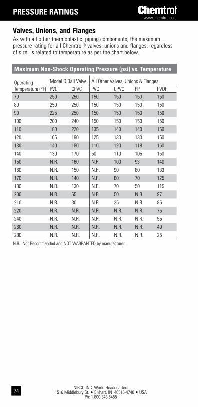
Valves, Unions, and FlangesAs with all other thermoplastic piping components, the maximum pressure rating for all Chemtrol® valves, unions and flanges, regardless of size, is related to temperature as per the chart below.
Maximum non-shock operating pressure (psi) vs. temperature
Operating Temperature (°F)
Model D Ball Valve All Other Valves, Unions & FlangesPVC CPVC PVC CPVC PP PVDF
70 250 250 150 150 150 150
80 250 250 150 150 150 150
90 225 250 150 150 150 150
100 200 240 150 150 150 150
110 180 220 135 140 140 150
120 165 190 125 130 130 150
130 140 180 110 120 118 150
140 130 170 50 110 105 150
150 N.R. 160 N.R. 100 93 140
160 N.R. 150 N.R. 90 80 133
170 N.R. 140 N.R. 80 70 125
180 N.R. 130 N.R. 70 50 115
200 N.R. 65 N.R. 50 N.R. 97
210 N.R. 30 N.R. 25 N.R. 85
220 N.R. N.R. N.R. N.R. N.R. 75
240 N.R. N.R. N.R. N.R. N.R. 55
260 N.R. N.R. N.R. N.R. N.R. 40
280 N.R. N.R. N.R. N.R. N.R. 25
N.R. Not Recommended and NOT WARRANTED by manufacturer.
pREssURE Ratings
www.chemtrol.com
NIBCO INC. World Headquarters 1516 Middlebury St. • Elkhart, IN 46516-4740 • USA
Ph: 1.800.343.545525
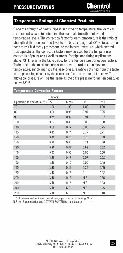
Since the strength of plastic pipe is sensitive to temperature, the identical test method is used to determine the material strength at elevated temperature levels. The correction factor for each temperature is the ratio of strength at that temperature level to the basic strength at 73° F. Because the hoop stress is directly proportional to the internal pressure, which created that pipe stress, the correction factors may be used for the temperature correction of pressure as well as stress. For pipe and fitting applications above 73° F, refer to the table below for the Temperature Correction Factors. To determine the maximum non-shock pressure rating at an elevated temperature, simply multiply the base pressure rating obtained from the table in the preceding column by the correction factor from the table below. The allowable pressure will be the same as the base pressure for all temperatures below 73° F.
temperature correction Factors
Operating Temperature (°F)FactorsPVC CPVC PP PVDF
70 1.00 1.00 1.00 1.00
80 0.90 0.96 0.97 0.95
90 0.75 0.92 0.91 0.87
100 0.62 0.85 0.85 0.80
110 0.50 0.77 0.80 0.75
115 0.45 0.74 0.77 0.71
120 0.40 0.70 0.75 0.68
125 0.35 0.66 0.71 0.66
130 0.30 0.62 0.68 0.62
140 0.22 0.55 0.65 0.58
150 N.R. 0.47 0.57 0.52
160 N.R. 0.40 0.50 0.49
170 N.R. 0.32 0.26 0.45
180 N.R. 0.25 * 0.42
200 N.R. 0.18 N.R. 0.36
210 N.R. 0.15 N.R. 0.33
240 N.R. N.R. N.R. 0.25
280 N.R. N.R. N.R. 0.18
* Recommended for intermittent drainage pressure not exceeding 20 psi. N.R. Not Recommended and NOT WARRANTED by manufacturer.
pREssURE Ratings
temperature Ratings of chemtrol products

NIBCO INC. World Headquarters 1516 Middlebury St. • Elkhart, IN 46516-4740 • USA
Ph: 1.800.343.5455
www.chemtrol.com
26
pREssURE Ratings
chemtrol products in Vacuum or collapse loading situationsThermoplastic pipe is often used in applications where the pressure on the outside of the pipe exceeds the pressure inside. Suction or vacuum lines and buried pipe are examples of this type of service.
As a matter of practical application, gauges indicate the pressure differential above or below atmospheric pressure. However, scientists and engineers frequently express pressure on an absolute scale where zero equals a theoretically perfect vacuum and standard atmospheric pressure equals 14.6959 psi.
Vacuum Conversion Factors: See page 12 for additional head and metric factors.
Solvent cemented or thermo-sealed joints are particularly recommended for vacuum service. In PVC, CPVC, PP, or PVDF vacuum systems, mechanical devices such as valves and transition joints at equipment will generally represent a greater intrusion problem than the thermoplastic piping system will. Experience indicates that PVC vacuum systems can be evacuated to pressures as low as 5 microns with continuous pumping. However, when the system is shut off, the pressure will rise and stabilize around 10,000 microns or approximately 10 mm of Mercury at 73° F.
The following chart lists the allowable collapse loading for plastic pipe at 73° F. It shows how much greater the external pressure may be than the internal pressure. (Thus, a pipe with 100 psi internal pressure can withstand 100 psi more external pressure than a pipe with zero psi internal pressure.) For temperatures other than 73° F, multiply the values in the chart by the correction factors listed in the temperature correction table on the preceding page.
The chart also applies to a vacuum. The external pressure is generally atmospheric pressure, or 0.0 psig, while the internal pressure is normally identified as a vacuum or negative gauge pressure. However, this negative value will never exceed –14.7 psig. Therefore, if the allowable pressure listed in the chart (after temperature correction) is greater than the difference for internal-to-external pressure, the plastic system is viable.
pressure Ratings of chemtrol products

www.chemtrol.com
NIBCO INC. World Headquarters 1516 Middlebury St. • Elkhart, IN 46516-4740 • USA
Ph: 1.800.343.545527
pREssURE loss
Maximum collapse pressure Rating, psi @73°F
Pipe SizePVC Sch. 40
PVC Sch. 80
CPVC Sch. 80
PP Sch. 80
PVDF Sch. 80
1/2 450 575 575 230 391
3/4 285 499 499 200 339
1 245 469 469 188 319
1 1/4 160 340 340 136 —
1 1/2 120 270 270 108 183
2 75 190 190 76 129
2 1/2 100 220 220 — —
3 70 155 155 62 105
4 45 115 115 46 78
6 25 80 80 32 54
8 16 50 50 — —
10 12 43 — — —
12 9 39 — — —
pressure losses in a piping system
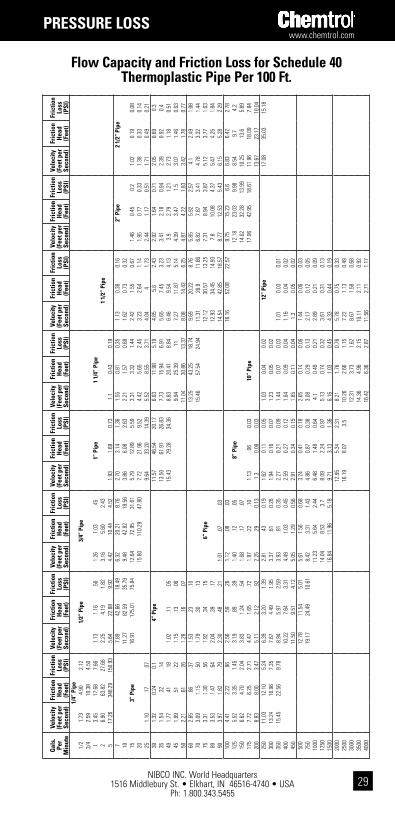
Piping CalculationsAs a fluid flows through a piping system, it will experience a head loss depending on, among other factors, fluid velocity, pipe wall smoothness and internal pipe surface area. The Tables on pages 15 and 16 give Friction Loss and Velocity data for Schedule 40 and Schedule 80 thermoplastic pipe based on the Williams and Hazen formula.
100 q 1.852H = .2083 -------
1.852 x -----------
C d 4.8655( ) ( )Where: H = Friction Head Loss in Feet of Water/100 Feet of Pipe C = Surface Roughness Constant (150 for all thermoplastic pipe) q = Fluid Flow (gallons/min.) d = Inside Diameter of Pipe
Fittings and valves, due to their more complex configurations, contribute significant friction losses in a piping system. A common method of expressing the losses experienced in fittings is to relate them to pipe in terms of equivalent pipe length. This is the length of pipe required to give the same friction loss as a fitting of the same size. The Table at the bottom of page 16 is a tabulation of the equivalent pipe length in feet for the various sizes of a number of common fittings. By using this Table and the Friction Loss Tables, the total friction loss in a plastic piping sys-tem can be calculated for any fluid velocity.
For example, suppose we wanted to determine the pressure loss across

NIBCO INC. World Headquarters 1516 Middlebury St. • Elkhart, IN 46516-4740 • USA
Ph: 1.800.343.5455
www.chemtrol.com
28
Piping Calculationsa 2" Schedule 40, 90° elbow, at 75 gpm. From the lower table on page 16 we find the equivalent length of a 2" 90° elbow to be 5.5 feet of pipe. From the Schedule 40 Pipe Table on page 15 we find the friction loss to be 3.87 psi per 100 feet of pipe when the flow rate is 75 gpm. Therefore, the solution is as follows: 5.5 Feet/90° Elbow x 3.87 psi/100 Feet = 0.21 psi Pressure Drop/90° Elbowwhich is the pressure drop across a 2" Schedule 40 elbow. But, what if it were a 2" Schedule 80 elbow, and we wanted to know the friction head loss? The solution is similar, except we look for the friction head in the Schedule 80 Pipe Table at the top of page 16 and find it to be 12.43 feet per 100 feet of pipe when the flow rate is 75 gpm. The solution follows: 5.5 Feet/90° Elbow x 12.43 Feet/100 Feet = 0.68 Feet Friction Head/90° Elbowwhich is the friction head loss across a 2" Schedule 80 elbow.
Valve CalculationsAs an aid to system design, fluid flow coefficients (Cv values) are shown for all Chemtrol valves. Cv is defined as the flow, in GPM, through a valve which will produce a pressure drop of 1.0 PSI when the medium is water at 60°F.
To determine the pressure drop for a given condition, the following formula may be used:
Q2 S.G.P = -------------- Cv2
Where: P = Pressure drop across the valve in psi Q = Flow through the valve in gpm S.G. = Specific gravity of the liquid (Water = 1.0) Cv = Flow coefficient
The solution for an example problem follows. For Cv values for specific valves, refer to the product description page in the Chemtrol PVC & CPVC Guide.
ExAMPLE:Find the pressure drop across a 1 1/2" PVC ball check valve with a water flow rate of 50 gpm.
The Cv is 56, as shown in the Chemtrol PVC & CPVC Guide.
(50)2 x 1.0P = -------------------- (56)2
P = .797 psi
50 2P = ----------- 56 ( )
pREssURE loss
www.chemtrol.com
NIBCO INC. World Headquarters 1516 Middlebury St. • Elkhart, IN 46516-4740 • USA
Ph: 1.800.343.545529
Gal
s.
Per
Min
ute
Velo
city
(F
eet p
er
Seco
nd)
Fric
tion
Hea
d (F
eet)
Fric
tion
Loss
(P
SI)
Velo
city
(F
eet p
er
Seco
nd)
Fric
tion
Hea
d (F
eet)
Fric
tion
Loss
(P
SI)
Velo
city
(F
eet p
er
Seco
nd)
Fric
tion
Hea
d (F
eet)
Fric
tion
Loss
(P
SI)
Velo
city
(F
eet p
er
Seco
nd)
Fric
tion
Hea
d (F
eet)
Fric
tion
Loss
(P
SI)
Velo
city
(F
eet p
er
Seco
nd)
Fric
tion
Hea
d (F
eet)
Fric
tion
Loss
(P
SI)
Velo
city
(F
eet p
er
Seco
nd)
Fric
tion
Hea
d (F
eet)
Fric
tion
Loss
(P
SI)
Velo
city
(F
eet p
er
Seco
nd)
Fric
tion
Hea
d (F
eet)
Fric
tion
Loss
(P
SI)
Velo
city
(F
eet p
er
Seco
nd)
Fric
tion
Hea
d (F
eet)
Fric
tion
Loss
(P
SI)
1/4”
Pip
e1/
21.
734.
902.
121/
2” P
ipe
3/4”
Pip
e3/
42.
5910
.38
4.50
13.
4517
.68
7.66
1.13
1.16
.50
1.26
1.03
.45
1” P
ipe
1 1
/4”
Pipe
26.
9063
.82
27.6
62.
254.
191.
823.
165.
602.
431
1/2”
Pip
e5
17.2
634
8.29
150.
935.
6422
.88
9.92
4.42
10.4
44.
521.
931.
690.
731.
10.
430.
197
7.89
42.6
618
.49
6.32
20.2
18.
762.
703.
141.
361.
550.
810.
351.
130.
380.
162”
Pip
e 2
1/2
” Pi
pe10
11.2
782
.59
35.7
99.
4842
.82
18.5
63.
866.
082.
632.
211.
570.
681.
620.
730.
3215
3” P
ipe
16.9
117
5.01
75.8
412
.64
72.9
531
.61
5.79
12.8
95.
593.
313.
321.
442.
421.
550.
671.
460.
450.
21.
020.
190.
0820
15.8
011
0.29
47.8
07.
7221
.96
9.52
4.42
5.65
2.45
3.23
2.64
1.14
1.95
0.77
0.33
1.38
0.33
0.14
251.
10.1
7.0
79.
6433
.20
14.3
95.
528.
553.
714.
044
1.73
2.44
1.17
0.51
1.71
0.49
0.21
301.
320.
240.
14”
Pip
e11
.57
46.5
420
.17
6.63
11.9
85.
194.
855.
62.
432.
921.
640.
712.
050.
690.
335
1.54
.32
.14
13.5
061
.91
26.8
37.
7315
.94
6.91
5.65
7.45
3.23
3.41
2.18
0.94
2.39
0.92
0.4
401.
77.4
1.1
81.
02.1
1.0
515
.43
79.2
834
.36
8.83
20.4
18.
846.
469.
544.
133.
92.
791.
212.
731.
180.
5145
1.99
.51
.22
1.15
.13
.06
9.94
25.3
911
7.27
11.8
75.
144.
393.
471.
53.
071.
460.
6350
2.21
.61
.26
1.28
.16
.07
11.0
430
.86
13.3
78.
0814
.43
6.25
4.87
4.22
1.83
3.42
1.78
0.77
602.
65.8
6.3
71.
53.2
3.1
013
.25
43.2
518
.74
9.69
20.2
28.
765.
855.
922.
574.
12.
491.
0870
3.09
1.15
.50
1.79
.30
.13
15.4
657
.54
24.9
411
.31
26.9
11.6
66.
827.
873.
414.
783.
321.
4475
3.31
1.30
.56
1.92
.34
.15
6”
Pipe
12.1
230
.57
13.2
57.
318.
943.
875.
123.
771.
6380
3.53
1.47
.64
2.04
.39
.17
12.9
334
.45
14.9
37.
810
.08
4.37
5.47
4.25
1.84
903.
971.
82.7
92.
30.4
8.2
11.
01.0
7.0
314
.54
42.8
518
.57
8.77
12.5
35.
436.
155.
282.
2910
04.
412.
22.9
62.
56.5
9.2
61.
12.0
8.0
316
.16
52.0
822
.57
9.75
15.2
36.
66.
836.
422.
7812
55.
523.
351.
453.
19.8
9.3
91.
40.1
2.0
5 8
” Pi
pe12
.18
23.0
39.
988.
549.
74.
215
06.
624.
702.
043.
831.
24.5
41.
68.1
7.0
714
.62
32.2
813
.99
10.2
513
.65.
8917
57.
726.
252.
714.
471.
65.7
21.
97.2
2.1
01.
13.0
60.
0310
” Pi
pe17
.06
42.9
518
.61
11.9
618
.09
7.84
200
8.83
8.00
3.47
5.11
2.12
.92
2.25
.29
0.13
1.3
0.08
0.03
13.6
723
.17
10.0
425
011
.03
12.1
05.
246.
393.
201.
392.
81.4
30.
191.
620.
110.
051.
030.
040.
02 1
2” P
ipe
17.0
835
.03
15.1
830
013
.24
16.9
67.
357.
674.
491.
953.
37.6
10.
261.
940.
160.
071.
230.
050.
0235
015
.45
22.5
69.
788.
945.
972.
593.
93.8
10.
352.
270.
210.
091.
440.
070.
031.
010.
030.
0140
010
.22
7.64
3.31
4.49
1.03
0.45
2.59
0.27
0.12
1.64
0.09
0.04
1.16
0.04
0.02
450
11.5
09.
514.
125.
051.
290.
562.
910.
340.
151.
850.
110.
041.
30.
050.
0250
012
.78
11.5
45.
015.
611.
560.
683.
240.
410.
182.
050.
140.
061.
440.
060.
0375
019
.17
24.4
910
.61
8.42
3.31
1.43
4.86
0.87
0.38
3.08
0.29
0.13
2.17
0.12
0.05
1000
11.2
35.
642.
446.
481.
480.
644.
10.
490.
212.
890.
210.
0912
5014
.04
8.53
3.7
8.09
2.24
0.97
5.13
0.74
0.32
3.61
0.31
0.13
1500
16.8
411
.96
5.18
9.71
3.13
1.36
6.16
1.03
0.45
4.33
0.44
0.19
2000
12.9
55.
342.
318.
211.
760.
765.
780.
750.
3325
0016
.19
8.07
3.5
10.2
62.
661.
157.
221.
130.
4930
0012
.31
3.73
1.62
8.67
1.58
0.68
3500
14.3
64.
962.
1510
.11
2.11
0.92
4000
16.4
26.
362.
8711
.56
2.71
1.17
Flow capacity and Friction loss for schedule 40 thermoplastic pipe per 100 Ft.
pREssURE loss

NIBCO INC. World Headquarters 1516 Middlebury St. • Elkhart, IN 46516-4740 • USA
Ph: 1.800.343.5455
www.chemtrol.com
30
Flow capacity and Friction loss for schedule 80 thermoplastic pipe per 100 Ft.
Gals.
Per M
inute
Velocity (Feet per Second)
Friction H
ead (Feet)
Friction Loss (PSI)
Velocity (Feet per Second)
Friction H
ead (Feet)
Friction Loss (PSI)
Velocity (Feet per Second)
Friction H
ead (Feet)
Friction Loss (PSI)
Velocity (Feet per Second)
Friction H
ead (Feet)
Friction Loss (PSI)
Velocity (Feet per Second)
Friction H
ead (Feet)
Friction Loss (PSI)
Velocity (Feet per Second)
Friction H
ead (Feet)
Friction Loss (PSI)
Velocity (Feet per Second)
Friction H
ead (Feet)
Friction Loss (PSI)
Velocity (Feet per Second)
Friction H
ead (Feet)
Friction Loss (PSI)
1/4” Pipe1/4
1.283.57
1.551/2" Pipe
1/22.57
12.885.58
3/4" Pipe3/4
3.8527.29
11.831.11
1.31.57
1" Pipe1
5.1446.49
20.151.48
2.24.97
.78.48
.211 1/4" Pipe
315.41
355.60154.20
4.4317.13
7.432.35
3.651.59
1.401.04
.451 1/2" Pipe
57.38
44.1219.12
3.929.45
4.102.33
9.451.16
1.30.64
.282" Pipe
710.33
82.2735.65
5.4817.62
7.643.26
4.982.16
1.821.20
.521.31
.54.23
2 1/2" Pipe10
3" Pipe14.76
159.2669.02
7.8434.11
14.784.66
9.654.18
2.592.32
1.011.87
1.05.46
1.12.30
.1315
11.7572.27
31.326.99
20.448.86
3.894.91
2.132.81
2.23.97
1.67.63
.271.17
.26.11
201.00
.15.07
15.67123.13
53.369.32
34.8215.09
5.198.36
3.623.75
3.801.65
2.231.07
.461.56
.45.20
251.24
.23.10
4” Pipe11.66
52.6422.81
6.4812.64
5.484.69
5.742.49
2.791.63
.711.92
.68.29
301.49
.32.14
13.9978.78
31.977.78
17.717.67
5.628.04
3.483.35
2.28.99
2.34.95
.4135
1.74.43
.191.00
.11.05
16.3298.16
42.549.08
23.5610.21
6.5610.70
4.643.91
3.031.31
2.731.26
.5540
1.99.54
.231.14
.14.06
10.3730.17
13.077.50
13.715.94
4.463.88
1.683.12
1.62.70
452.24
.68.29
1.28.17
.0711.67
37.5316.26
8.4417.05
7.395.02
4.382.09
3.502.01
.8750
2.49.82
.361.42
.21.09
12.9745.62
19.779.37
20.728.98
5.585.87
2.543.89
2.451.06
602.99
1.15.50
1.71.30
.1315.56
69.9427.71
11.2529.04
12.586.07
8.223.56
4.673.43
1.4970
3.491.54
.671.99
.39.17
6” Pipe13.12
38.6416.74
7.8110.94
4.745.45
4.561.98
753.73
1.74.75
2.14.45
.2014.06
43.9019.02
8.3712.43
5.395.84
5.182.24
803.98
1.97.85
2.28.51
.221.00
.07.03
15.0049.48
21.448.93
14.016.07
6.235.84
2.5390
4.482.45
1.062.56
.63.27
1.13.63
.2716.87
61.5426.67
10.0517.42
7.557.01
7.263.15
1004.98
2.971.29
2.85.76
.331.25
.10.04
8" Pipe11.16
21.189.18
7.798.83
3.83125
6.224.49
1.953.56
1.16.50
1.57.16
.0713.95
32.0213.88
9.7413.34
5.78150
7.476.30
2.734.27
1.62.70
1.88.22
.101.07
.06.03
16.7444.88
19.4511.68
18.708.10
1758.71
8.383.63
4.992.16
.942.19
.29.13
1.25.07
.0310" Pipe
13.6324.88
10.78200
9.9610.73
4.655.70
2.761.20
2.51.37
.161.43
.10.04
15.5831.86
13.81250
12.4516.22
7.037.12
4.171.81
3.13.57
.251.78
.14.06
1.13.05
.0212" Pipe
30014.94
22.749.85
8.555.85
2.543.76
.79.34
2.14.20
.091.36
.07.03
35017.43
30.2513.11
9.977.78
3.374.39
1.05.46
2.50.27
.121.59
.09.04
1.12.04
.02400
11.409.96
4.325.01
1.35.59
2.85.34
.151.81
.11.05
1.28.05
.02450
12.8512.39
5.375.64
1.68.73
3.21.43
.192.04
.14.06
1.44.06
.03500
14.2515.06
6.536.27
2.04.88
3.57.52
.232.27
.17.07
1.60.07
.03750
21.3731.92
13.839.40
4.331.88
5.351.10
.483.40
.36.16
2.40.16
.071000
12.537.37
3.197.14
1.87.81
4.53.62
.273.20
.27.12
125015.67
11.144.83
8.922.83
1.235.67
.94.41
4.00.40
.171500
10.713.97
1.726.80
1.32.57
4.81.57
.252000
14.276.76
2.939.07
2.24.97
6.41.96
.422500
17.8410.23
4.4311.33
3.391.47
8.011.46
.633000
13.604.74
2.069.45
1.96.85
350015.86
6.232.74
11.032.61
1.134000
12.603.34
1.45
pREssURE loss

www.chemtrol.com
NIBCO INC. World Headquarters 1516 Middlebury St. • Elkhart, IN 46516-4740 • USA
Ph: 1.800.343.545531
hydraulic shockHydraulic shock is the term used to describe the momentary pressure rise in a piping system which results when the liquid is started or stopped quickly. This pressure rise is caused by the momentum of the fluid; therefore, the pressure rise increases with the velocity of the liquid, the length of the system from the fluid source, or with an increase in the speed with which it is started or stopped. Examples of situations where hydraulic shock can occur are valves which are opened or closed quickly or pumps which start with an empty discharge line. Hydraulic shock can even occur if a high-speed wall of liquid (as from a starting pump) hits a sudden change of direction in the piping, such as an elbow.
The pressure rise created by the hydraulic shock effect is added to whatever fluid pressure exists in the piping system and, although only momentary, this shock load can be enough to burst pipe and break fittings or valves.
Proper design when laying out a piping system will limit the possibility of hydraulic shock damage.
The following suggestions will help in avoiding problems:
1. In a plastic piping system, a fluid velocity not exceeding 5 ft./sec. will minimize hydraulic shock effects, even with quickly closing valves, such as solenoid valves. (Flow is normally expressed in GALLONS PER MINUTE—GPM. To determine the fluid velocity in any segment of piping the following formula may be used) :
Where: v = fluid velocity in feet per second Di = inside diameter GPM = rate of flow in gallons per minute
See the Flow Capacity Tables on pages 15 and 16 for the fluid velocities resulting from specific flow rates in Schedule 40 and Schedule 80 pipes. The upper threshold rate of flow for any pipe may be determined by substituting 5 ft./sec. Fluid velocity in the above formula and solving for GPM.
Upper Threshold Rate of Flow (GPM) = 12.24 Di2
See the Pipe Reference Table on page 10 for the Upper Threshold Flow Rate in specific sizes of Schedule 80 Pipes.
.4085 GPMv = ----------- Di2
pREssURE loss

NIBCO INC. World Headquarters 1516 Middlebury St. • Elkhart, IN 46516-4740 • USA
Ph: 1.800.343.5455
www.chemtrol.com
32
shock surge wave Providing all air is removed from an affected system, a formula based on theory may closely predict hydraulic shock effect.
Where: p = maximum surge pressure, psi v = fluid velocity in feet per second (see Table on pages 15 and 16 for flow/velocity conversion). C = surge wave constant for water at 73° F. *SG = specific gravity of liquid
* if SG is 1, then p = vC
ExAMPLE: A 2" PVC Schedule 80 pipe carries a fluid with a specific gravity of 1.2 at a rate of 30 gpm and at a line pressure of 160 psi. What would the surge pressure be if a valve were suddenly closed?
From table below: From upper table on page 16: c = 24.2 v = 3.35
p = (3.35) (26.6) = 90 psi Total line pressure = 90 + 160 = 250 psi
Schedule 80 2" PVC from the chart on page 13 has a pressure rating of 400 psi at room temperature. Therefore, 2" Schedule 80 PVC pipe is acceptable for this application.
SG – 1 p = v ----------- C + C 2( )
(1.2 – 1) p = 3.35 --------------- 24.2 + 24.2 2( )
2. Using actuated valves, which have a specific closing time, will eliminate the possibility of someone inadvertently slamming a valve open or closed too quickly. With air-to-air and air-to-spring actuators, it will probably be necessary to place a flow control valve in the air line to slow down the valve operation cycle, particularly on valve sizes greater than 1 1/2".
3. If possible, when starting a pump, partially close the valve in the discharge line to minimize the volume of liquid that is rapidly accelerating through the system. Once the pump is up to speed and the line completely full, the valve may be opened.
4. A check valve installed near a pump in the discharge line will keep the line full and help prevent excessive hydraulic shock during pump start-up. Before initial start-up the discharge line should be vented of all air. Air trapped in the piping will substantially reduce the capability of plastic pipe withstanding shock loading.
pREssURE loss
www.chemtrol.com
NIBCO INC. World Headquarters 1516 Middlebury St. • Elkhart, IN 46516-4740 • USA
Ph: 1.800.343.545533
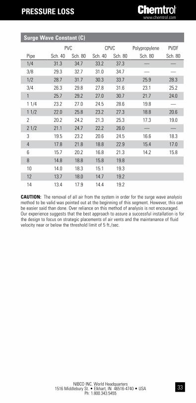
surge wave constant (c)
PVC CPVC Polypropylene PVDFPipe Sch. 40 Sch. 80 Sch. 40 Sch. 80 Sch. 80 Sch. 801/4 31.3 34.7 33.2 37.3 — —
3/8 29.3 32.7 31.0 34.7 — —
1/2 28.7 31.7 30.3 33.7 25.9 28.3
3/4 26.3 29.8 27.8 31.6 23.1 25.2
1 25.7 29.2 27.0 30.7 21.7 24.0
1 1/4 23.2 27.0 24.5 28.6 19.8 —
1 1/2 22.0 25.8 23.2 27.3 18.8 20.6
2 20.2 24.2 21.3 25.3 17.3 19.0
2 1/2 21.1 24.7 22.2 26.0 — —
3 19.5 23.2 20.6 24.5 16.6 18.3
4 17.8 21.8 18.8 22.9 15.4 17.0
6 15.7 20.2 16.8 21.3 14.2 15.8
8 14.8 18.8 15.8 19.8
10 14.0 18.3 15.1 19.3
12 13.7 18.0 14.7 19.2
14 13.4 17.9 14.4 19.2
caUtion: The removal of all air from the system in order for the surge wave analysis method to be valid was pointed out at the beginning of this segment. However, this can be easier said than done. Over reliance on this method of analysis is not encouraged. Our experience suggests that the best approach to assure a successful installation is for the design to focus on strategic placements of air vents and the maintenance of fluid velocity near or below the threshold limit of 5 ft./sec.
pREssURE loss
NIBCO INC. World Headquarters 1516 Middlebury St. • Elkhart, IN 46516-4740 • USA
Ph: 1.800.343.5455
www.chemtrol.com
34
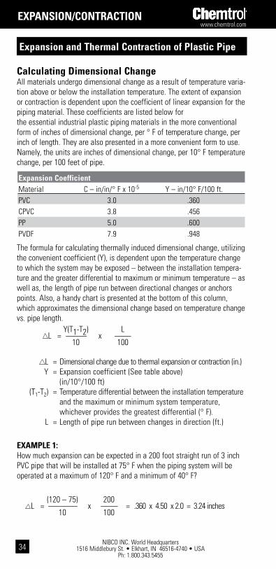
calculating dimensional changeAll materials undergo dimensional change as a result of temperature varia-tion above or below the installation temperature. The extent of expansion or contraction is dependent upon the coefficient of linear expansion for the piping material. These coefficients are listed below for the essential industrial plastic piping materials in the more conventional form of inches of dimensional change, per ° F of temperature change, per inch of length. They are also presented in a more convenient form to use. Namely, the units are inches of dimensional change, per 10° F temperature change, per 100 feet of pipe.
The formula for calculating thermally induced dimensional change, utilizing the convenient coefficient (Y), is dependent upon the temperature change to which the system may be exposed – between the installation tempera-ture and the greater differential to maximum or minimum temperature – as well as, the length of pipe run between directional changes or anchors points. Also, a handy chart is presented at the bottom of this column, which approximates the dimensional change based on temperature change vs. pipe length.
L = Dimensional change due to thermal expansion or contraction (in.) Y = Expansion coefficient (See table above) (in/10°/100 ft) (T1-T2) = Temperature differential between the installation temperature and the maximum or minimum system temperature, whichever provides the greatest differential (° F). L = Length of pipe run between changes in direction (ft.)
ExaMPLE 1:How much expansion can be expected in a 200 foot straight run of 3 inch PVC pipe that will be installed at 75° F when the piping system will be operated at a maximum of 120° F and a minimum of 40° F?
Expansion coefficient Material C – in/in/° F x 10-5 Y – in/10° F/100 ft.PVC 3.0 .360 CPVC 3.8 .456PP 5.0 .600 PVDF 7.9 .948
Y(T1-T2) LL = -------------- x -----------
10 100
(120 – 75) 200L = ------------------- x ----------- = .360 x 4.50 x 2.0 = 3.24 inches
10 100
Expansion and thermal contraction of plastic pipe
Expansion/contRaction

www.chemtrol.com
NIBCO INC. World Headquarters 1516 Middlebury St. • Elkhart, IN 46516-4740 • USA
Ph: 1.800.343.545535
to determine the expansion or contraction for pipe of a material other than pVc, multiply the change in length given for pVc in the table above by 1.2667 for the change in cpVc, by 1.6667 for the change in pp, or by 2.6333 for the change in pVdF.
Expansion or contraction of pVc pipe (in.)
Temp Change*
T°F
Length of Pipe to Closet Anchor Point (ft.)
10' 20' 30' 40' 50' 60' 70' 80' 90' 100'10° 0.04 0.07 0.11 0.14 0.18 0.22 0.25 0.29 0.32 0.36
20° 0.07 0.14 0.22 0.29 0.36 0.43 0.50 0.58 0.65 0.72
30° 0.11 0.22 0.32 0.43 0.54 0.65 0.76 0.86 0.97 1.08
40° 0.14 0.29 0.43 0.58 0.72 0.86 1.00 1.15 1.30 1.44
50° 0.18 0.36 0.54 0.72 0.90 1.08 1.26 1.44 1.62 1.80
60° 0.22 0.43 0.65 0.86 1.08 1.30 1.51 1.73 1.94 2.16
70° 0.25 0.50 0.76 1.01 1.26 1.51 1.76 2.02 2.27 2.52
80° 0.29 0.58 0.86 1.15 1.44 1.73 2.02 2.30 2.59 2.88
90° 0.32 0.65 0.97 1.30 1.62 1.94 2.27 2.59 2.92 3.24
100° 0.36 0.72 1.08 1.44 1.80 2.16 2.52 2.88 3.24 3.60
110° 0.40 0.79 1.19 1.58 1.98 2.38 2.77 3.17 3.56 3.96
120° 0.43 0.86 1.30 1.73 2.16 2.59 3.02 3.46 3.89 4.32
* Temperature change ( T) from installation to the greater of maximum or minimum limits.
Expansion/contRaction

NIBCO INC. World Headquarters 1516 Middlebury St. • Elkhart, IN 46516-4740 • USA
Ph: 1.800.343.5455
www.chemtrol.com
36
temperature vs. Modulus ( x 105) psi 73° F 90° F 100° F 140° F 180° F 210° F 250° FPVC 4.20 3.75 3.60 2.70 N/A N/A N/ACPVC 4.23 4.00 3.85 3.25 2.69 2.20 N/APP 1.79 1.25 1.15 .72 .50 N/A N/APVDF 2.19 1.88 1.74 1.32 1.12 .81 .59N/A - Not Applicable
The magnitude of the resulting longitudinal force can be determined by multiplying the thermally induced stress by the cross sectional area of the plastic pipe.
F = St x A
F = FORCE (lbs) St = STRESS (psi) A = CROSS SECTIONAL AREA (in2)
ExaMPLE 2:What would be the amount of force developed in 2" Schedule 80 PVC pipe with the pipe rigidly held and restricted at both ends? Assume the temperature extremes are from 70° F to 100° F.
St = EC (T1 – T2) St = EC (100 – 70) St = (3.60 x 105) x (3.0 x 10-5) (30) St = 324 psi
calculating stressIf movement resulting from thermal changes is restricted by the piping support system or the equipment to which it is attached, the resultant forces may damage the attached equipment or the pipe itself. Therefore, pipes should always be anchored independently at those attachments. If the piping system is rigidly held or restricted at both ends when no compensation has been made for thermally induced growth or shrinkage of the pipe, the resultant stress can be calculated with the following formula.
St = EC (T1-T2) St = Stress (psi) E = Modulus of Elasticity (psi) (See table below for specific values at various temperatures) C = Coefficient of Expansion (in/in/ ° F x 105) (see physical property chart on page 8 for values) (T1-T2) = Temperature change (° F) between the installation temperature and the maximum or minimum system temperature, whichever provides the greatest differential.
Expansion/contRaction

www.chemtrol.com
NIBCO INC. World Headquarters 1516 Middlebury St. • Elkhart, IN 46516-4740 • USA
Ph: 1.800.343.545537
The Outside and Inside Diameters of the pipe are used for calculating the Cross Sectional Area (A) as follows: (See the Pipe Reference Table on page 10 for the pipe diameters and cross sectional area for specific sizes of schedule 80 Pipes.)
A = π/4 (OD2 – ID2) = 3.1416/4 (2.3752 – 1.9132) = 1.556 in.2
The force exerted by the 2" pipe, which has been restrained, is simply the compressive stress multiplied over the cross sectional area of that pipe.
F = St x A F = 324 psi x 1.556 in.2
F = 504 lbs.
Expansion/contRaction

NIBCO INC. World Headquarters 1516 Middlebury St. • Elkhart, IN 46516-4740 • USA
Ph: 1.800.343.5455
www.chemtrol.com
38
Stresses and forces which result from thermal expansion and contraction can be reduced or eliminated by providing for flexibility in the piping system through frequent changes in direction or introduction of loops as graphically depicted on this page.
Normally, piping systems are designed with sufficient directional changes, which provide inherent flexibility, to compensate for expansion and contraction. To determine if adequate flexibility exists in leg (R) (see Fig. 1) to accommodate the expected expansion and contraction in the adjacent leg (L) use the following formula:
R = 2.877√D L SINGLE OFFSET FORMULA
Where: R = Length of opposite leg to be flexed (ft.) D = Actual outside diameter of pipe (in.) L = Dimensional change in adjacent leg due to thermal expansion or contraction (in.)
Keep in mind the fact that both pipe legs will expand and contract. Therefore, the shortest leg must be selected for the adequacy test when analyzing inherent flexibility in naturally occurring offsets.
ExaMPLE 3:What would the minimum length of a right angle leg need to be in order to compensate for the expansion if it were located at the unanchored end of the 200 ft. run of pipe in Example 1 from the previous page?
R = 2.877√3.500 x 3.24 = 9.69 ft.
Flexibility must be designed into a piping system, through the introduction of flexural offsets, in the following situations:1. Where straight runs of pipe are long.2. Where the ends of a straight run are restricted from movement.3. Where the system is restrained at branches and/or turns.
Managing Expansion/contraction in system design
Expansion/contRaction

www.chemtrol.com
NIBCO INC. World Headquarters 1516 Middlebury St. • Elkhart, IN 46516-4740 • USA
Ph: 1.800.343.545539
Several examples of methods for providing flexibility in these situations are graphically presented below. In each case, rigid supports or restraints should not be placed on a flexible leg of an expansion loop, offset or bend.
An expansion loop (which is fabricated with 90° elbows and straight pipe as depicted in Fig. 2) is simply a double offset designed into an otherwise straight run of pipe. The length for each of the two loop legs (R'), required to accommodate the expected expansion and contraction in the pipe run (L), may be determined by modification of the SINGLE OFFSET FORMULA to produce a LOOP FORMULA, as shown below:
R' = 2.041√ D L LOOP FORMULA
ExaMPLE 4:How long should the expansion loop legs be in order to compensate for the expansion in Example 1 from the previous page?
R' = 2.041√ 3.500 x 3.24 = 6.87 ft.
Expansion/contRaction

NIBCO INC. World Headquarters 1516 Middlebury St. • Elkhart, IN 46516-4740 • USA
Ph: 1.800.343.5455
www.chemtrol.com
40
Minimum Cold Bending RadiusThe formulae above for Single Offset and Loop bends of pipe, which are designed to accommodate expansion or contraction in the pipe, are derived from the fundamental equation for a cantilevered beam – in this case a pipe fixed at one end. A formula can be derived from the same equation for calculating the minimum cold bending radius for any thermoplastic pipe diameter.
Minimum Cold Bend Radius
RB = DO (0.6999 E/SB – 0.5)
Where: RB = Minimum Cold Bend Radius (in.) DO = Outside Pipe Diameter (in.) E * = Modulus of Elasticity @ Maximum Operating Temperature (psi) SB * = Maximum Allowable Bending Stress @ Maximum Operating Temperature (psi)
*The three formulae on this page provide for the maximum bend in pipe while the pipe operates at maximum long-term internal pressure, creating maximum allowable hydrostatic design stress (tensile stress in the hoop direction). Accordingly, the maximum allowable bending stress will be one-half the basic hydraulic design stress at 73° F with correction to the maximum operating temperature. See the table at the top of the second column on page 13. The modulus of elasticity, corrected for temperature may be found in the table in the second column of the preceding page.
ExaMPLE 5:What would be the minimum cold radius bend, which the installer could place at the anchored end of the 200 ft. straight run of pipe in Examples 1 and 3, when the maximum operating temperature is 100° F instead of 140°?
RB = 3.500 (0.6999 x 360,000/ 1/2 x 2000 x 0.62 – 0.5) =1,420.8 inches or 118.4 feet
Expansion/contRaction
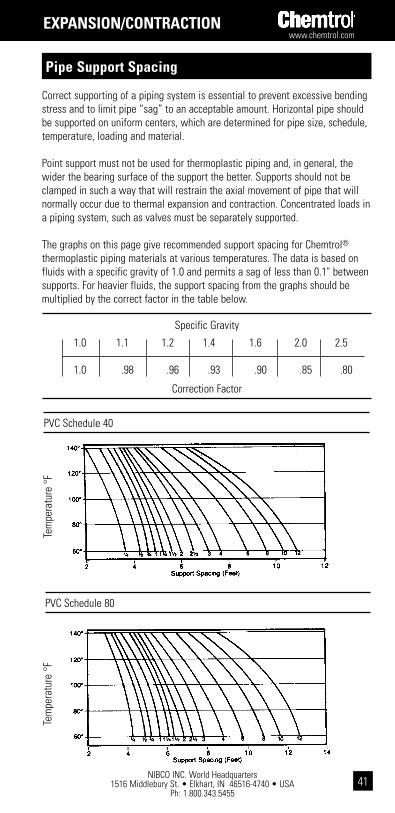
www.chemtrol.com
NIBCO INC. World Headquarters 1516 Middlebury St. • Elkhart, IN 46516-4740 • USA
Ph: 1.800.343.545541
Correct supporting of a piping system is essential to prevent excessive bending stress and to limit pipe “sag” to an acceptable amount. Horizontal pipe should be supported on uniform centers, which are determined for pipe size, schedule, temperature, loading and material.
Point support must not be used for thermoplastic piping and, in general, the wider the bearing surface of the support the better. Supports should not be clamped in such a way that will restrain the axial movement of pipe that will normally occur due to thermal expansion and contraction. Concentrated loads in a piping system, such as valves must be separately supported.
The graphs on this page give recommended support spacing for Chemtrol® thermoplastic piping materials at various temperatures. The data is based on fluids with a specific gravity of 1.0 and permits a sag of less than 0.1" between supports. For heavier fluids, the support spacing from the graphs should be multiplied by the correct factor in the table below.
PVC Schedule 40
Tem
pera
ture
°F
Tem
pera
ture
°F
PVC Schedule 80
pipe support spacing
Specific Gravity
Correction Factor
1.0 1.1 1.2 1.4 1.6 2.0 2.5
1.0 .98 .96 .93 .90 .85 .80
Expansion/contRaction

NIBCO INC. World Headquarters 1516 Middlebury St. • Elkhart, IN 46516-4740 • USA
Ph: 1.800.343.5455
www.chemtrol.com
42
The above data is for uninsulated lines. For insulated lines, reduce spans to 70% of graph values. For spans of less than 2 feet, continuous support should be used.
Polypropylene Schedule 80
Tem
pera
ture
°F
CPVC Schedule 80
PVDF (KYNAR®) Schedule 80
Tem
pera
ture
°F
Tem
pera
ture
°F
Kynar® is a registered trademark of Arkema Inc.
Expansion/contRaction

www.chemtrol.com
NIBCO INC. World Headquarters 1516 Middlebury St. • Elkhart, IN 46516-4740 • USA
Ph: 1.800.343.545543
introduction
This chemical resistance guide has been compiled to assist the piping system designer in selecting chemical-resistant materials. The information given is intended as a guide only. Many conditions can affect the material choices. Careful consideration must be given to temperature, pressure and chemical concentrations before a final material can be selected by the system designer.
MaTERIaL RaTINGS FOR THERMOPLaSTICS & ELaSTOMERS
Temp. in °F = Maximum temperature recommended under normal conditions
B to Temp. in °F = Conditional resistance, consult NIBCO Technical Services: 888.446.4226
C = Not recommended
Blank = No data available, consult NIBCO Technical Services: 888.446.4226
Temperature maximums for thermoplastics, elastomers and metals should always fall within published temp/pressure ratings and manufacturer's recommendations for individual valves.
WaRNING: THERMOPLaSTICS aRE NOT RECOMMENDED FOR COMPRESSED aIR OR GaS SERVICE.*
This guide considers the resistance of the total valve assembly as well as the resistance of individual trim and fitting materials. The rating assigned to the valve body plus trim combinations is always that of the least resistant part. In the cases where the valve body is the least resistant, there may be conditions under which the rate of corrosion is slow enough and the mass of the body large enough to be usable for a period of time. Such use should always be determined by test before installation of the component in a piping system.
In the selection of a butterfly valve for use with a particular chemical, the liner, disc, and stem must be resistant. All three materials should carry a rating of “A.” The body of a properly functioning butterfly valve is isolated from the chemicals being handled and need not carry the same rating.
chEMical REsistancE

NIBCO INC. World Headquarters 1516 Middlebury St. • Elkhart, IN 46516-4740 • USA
Ph: 1.800.343.5455
www.chemtrol.com
44
chemical Resistance guide for Valves & Fittings
chEMicals
and
FoRMUla
con
cEn
tRat
ion
plastics Max tEMpERatURE (°F)
sEal MatERials Max tEMpERatURE (°F)
ab
s
cp
Vc
pp
pV
c
pV
dF
pEx
pp
sU
ptF
E
Epd
M
nit
Ril
E (b
una-
n)
po
lYc
hlo
Ro
-p
REn
E
FkM
gR
ap
hit
E
Acetaldehyde CH3CHO Conc. C 140 C C 350
B to
200C C C A
Acetamide CH3CONH2 200
B to
200
B to
180
B to
200C
Acetic Acid CH3COOH 25% C 180 180 140 140
B to 73
350 176 C 70 C A
Acetic Acid CH3COOH 50%
B to
140
B to
176350 140 C C C A
Acetic Acid CH3COOH 85% C C 120 73 73 350 70 C C C A
Acetic Acid CH3COOH Glacial C C 120 73
B to
104
B to 68
350 A
Acetic Anhydride (CH3CO)2O C C 73 C C 73 350 C C
B to 70
C A
Acetone CH3COCH3 C C B C B C C 350
B to
300C C C A
Acetophenone C6H5COCH3
350B to
176C C C
Acetyl Chloride CH3COCI C C C C 200 C C C B
Acetylene Gas, 100% 73 C 73 C 73 250
B to
250200 104 200
Acrylonitrile H2C=CHCN C C 140 350 104 C C C A
Adipic Acid COOH(CH2)4COOH
Sat'd. 180 140 140B to
176140 350 140
B to
220
B to
160176
Allyl Alcohol CH2=CHCH2OH 96% C 140
B to 73
C 250B to
300
B to
180
B to
120
B to 70
Allyl Chloride CH2=CHCH2CI C C 140 C 350 C
B to 70
C C
Aluminum Acetate AI(C2H4O2)3
Sat'd. 350 176 C C C
chEMical REsistancE
c-cRg-0613

www.chemtrol.com
NIBCO INC. World Headquarters 1516 Middlebury St. • Elkhart, IN 46516-4740 • USA
Ph: 1.800.343.545545
Aluminum Ammonium Sulfate (Alum) AINH4(SO4)212H2O
Sat'd. 180 140 140 140 250B to
200
B to
140C 190 A
Aluminum Chlo-ride (Aqueous) AICI3
Sat'd. 160 180 180 140B to
212140 250 176
B to
200
B to
200176 A
Aluminum Fluoride AIF3 Sat'd. 160 180 180 73
B to
212140 250
B to
300
B to
200
B to
200176 A
Aluminum Hy-droxide AI(OH)3
Sat'd. 160 180 180 140B to
212140 250 176 160
B to
180176
Aluminum Nitrate AI(NO3)3•9H2O Sat'd. 180 180 140
B to
212140 250 176 140
B to
200
B to
400A
Aluminum Potassium Sulfate (Alum) AIK(SO4)2•12H2O
Sat'd. 160 180 140 140B to
212140 400
B to
200
B to
200
B to
200248 A
Aluminum Sulfate (Alum) AI2(SO4)3
Sat'd. 160 180 140 140B to
212140 250
B to
300
B to
300
B to
200
B to
390A
Ammonia Gas NH3 100% C C 140 140 140 400 140
B to
140140 C A
Ammonia Liquid NH3 100% 160 C 140 C 140 400 212 70
B to
160C A
Ammo-nium Acetate CH3COONH4
Sat'd. 120 180 73 140B to
212140 400 140 140 140
Ammonium Bi-fluoride NH4HF2 Sat'd. 180 180 140 140 400 140
B to
140C 140 A
Ammo-nium Carbonate (NH4)2CO3
Sat'd. 180 212 140B to
248140 400 176
B to
200
B to
200212
Ammonium Chloride NH4CI Sat'd. 120 180 212 140
B to
212140 400 300
B to
200
B to
212250 A
Ammonium Fluoride NH4F 10% 120 180 212 140
B to
212140 400 300
B to
200
B to
100140 A
Ammonium Fluoride NH4F 25% 120 180 212 C 140 400 300
B to
120
B to
100140 A
chEMicals
and
FoRMUla co
ncE
ntR
atio
n
plastics Max tEMpERatURE (°F)
sEal MatERials Max tEMpERatURE (°F)
ab
s
cp
Vc
pp
pV
c
pV
dF
pEx
pp
sU
ptF
E
Epd
M
nit
Ril
E (b
una-
n)
po
lYc
hlo
Ro
-p
REn
E
FkM
gR
ap
hit
E
chEMical REsistancE
c-cRg-0613

NIBCO INC. World Headquarters 1516 Middlebury St. • Elkhart, IN 46516-4740 • USA
Ph: 1.800.343.5455
www.chemtrol.com
46
Ammonium Hydroxide NH4OH 10% 120 C 212 140 140 400
B to
300200 200
B to
190A
Ammonia Hydrox-ide NH4OH Sat'd. 400
B to
300C 200
B to
190A
Ammonium Nitrate NH4NO3 Sat'd. 120 180 212 140
B to
212140 400
B to
300200 200 176 A
Ammo-nium Persulphate (NH4)2S2O8
180 140 140B to
212140 200
B to 70
C 70B to
140
Ammonium Phosphate (Monobasic) NH4H2PO4
All 120 180 212 140B to
248140 400
B to
200200
B to
200
B to
180A
Ammonium Sul-fate (NH4)2SO4 120 180 212 140
B to
212140 400 300 200 200 176 A
Ammonium Sulfide (NH4)2S Dilute 120 180 212 140 140 350
B to
300
B to
180
B to
160
B to 70
Ammonium Thio-cyanate NH4SCN
50 - 60% 120 180 212 140
B to
21273
B to
300
B to
180
B to
200
B to
190
Amyl Acetate CH3COOC5H11 C C C C
B to
12273 100 210 C C C
Amyl Alcohol C5H11OH C C
B to
212
B to
140400
B to
300
B to
180
B to
200
B to
212A
n-Amyl Chloride CH3(CH2)3CH2Cl C C C C C 400 C C C 200
Aniline C6H5NH2 C C C
B to 68
C 200B to
140C C
B to 70
A
Aniline Hydrocloride C6H5NH2•HCI
Sat'd. C C 140 C
Anthraquinone C14H8O2 180 140 C C
Anthraquinone Sulfonic Acid C14H7O2•SO3•H2O
180 73 140 C
Antimony Trichlo-ride SbCI3 Sat'd. 180 140 140
B to
140140 C 70
B to 70
70 A
chEMicals
and
FoRMUla
con
cEn
tRat
ion
plastics Max tEMpERatURE (°F)
sEal MatERials Max tEMpERatURE (°F)
ab
s
cp
Vc
pp
pV
c
pV
dF
pEx
pp
sU
ptF
E
Epd
M
nit
Ril
E (b
una-
n)
po
lYc
hlo
Ro
-p
REn
E
FkM
gR
ap
hit
E
chEMical REsistancE
c-cRg-0613

www.chemtrol.com
NIBCO INC. World Headquarters 1516 Middlebury St. • Elkhart, IN 46516-4740 • USA
Ph: 1.800.343.545547
chEMicals
and
FoRMUla co
ncE
ntR
atio
n
plastics Max tEMpERatURE (°F)
sEal MatERials Max tEMpERatURE (°F)
ab
s
cp
Vc
pp
pV
c
pV
dF
pEx
pp
sU
ptF
E
Epd
M
nit
Ril
E (b
una-
n)
po
lYc
hlo
Ro
-p
REn
E
FkM
gR
ap
hit
E
Aqua Regia (Nitrohydrochloric Acid)
CB to 73
C C C C 200 C C CB to
190C
Argon Ar Dry 350B to
400250
B to
100
B to
500
Arsenic Acid H3AsO4
80% 180 140 140B to
248140 400
B to
176
B to
200
B to
180140 A
Asphalt C 73 C 73 350 C C C 212
Barium Carbonate BaCO3 Sat'd. 120 180 140 140
B to
248140 400
B to
300140
B to
160248
Barium Chloride BaCI2•2H2O Sat'd. 120 180 140 140
B to
212140 400
B to
300
B to
200
B to
160
B to
400A
Barium Hydroxide Ba(OH)2 Sat'd. 73 180 140 140 400
B to
300
B to
220
B to
200248
Barium Nitrate Ba(NO3)2 Sat'd. 73 180 140 73 140 250 176 140
B to
200248 A
Barium Sulfate BaSO4 Sat'd. 73 180 140 140
B to
212140 400
B to
300
B to
200
B to
200
B to
380A
Barium Sulfide BaS Sat'd. 73 180 140 140 400
B to
310
B to
200
B to
200
B to
400
Beer 120 180 180 140B to
248
B to
140300 120
B to
250
B to
140
B to
300
Beet Sugar Liquors 180 180 140 73
B to
300200
B to
180
B to
400
Benzaldehyde C6H5CHO 10% C
B to 73
73B to 73
73 200 C C C A
Benzene C6H6 C C C C C
B to 68
C 250 C C CB to
140A
Benzene Sulfonic Acid C6H5SO3H 10% 180 180 140
B to 73
C CB to
100200
Benzoic Acid C6H5COOH 160 180 73 140 350 C C
B to
150176
Benzyl Alcohol C6H5CH2OH C 120 C
B to
122140 400 C C
B to 70
B to
250
chEMical REsistancE
c-cRg-0613

NIBCO INC. World Headquarters 1516 Middlebury St. • Elkhart, IN 46516-4740 • USA
Ph: 1.800.343.5455
www.chemtrol.com
48
chEMicals
and
FoRMUla
con
cEn
tRat
ion
plastics Max tEMpERatURE (°F)
sEal MatERials Max tEMpERatURE (°F)
ab
s
cp
Vc
pp
pV
c
pV
dF
pEx
pp
sU
ptF
E
Epd
M
nit
Ril
E (b
una-
n)
po
lYc
hlo
Ro
-p
REn
E
FkM
gR
ap
hit
E
Bismuth Carbon-ate (BiO)2CO3 180 180 140 140 70 70 70
B to
200
Black Liquor Sat'd. 180 140 140 120 225 220 140 70 212
Bleach (Sodium Hypo-chlorite)
12% Cl 73 185 120 140 73
Blood 200 70 C 70 70
Borax Na3B4O7•10H2O Sat'd. 160 180 212 140 140 300
B to
200
B to
200200
Boric Acid H3BO3 Sat'd. 160 180 212 140
B to
212140
B to
300
B to
200
B to
200185 A
Brine Sat'd. 180 140 140 140 400 B B B B
Bromic Acid HBrO3 180 C 140
B to
212C 200 C C 200
Bromine Br2 Liquid 73 C C C
B to
248C 300 C C C
B to
350C
Bromine Br2
Gas, 25% 180 C 140 C 200 C C C
B to
180C
Bromine Water Sat'd. 180 C 140B to
176C 300 C C C
B to
210C
Butadiene H2C=CHHC=CH2 50% 180 C 140 73 C C C C 70
Butane C4H10 50% 180 140 140 140 73 350 C
B to
250
B to
200
B to
400
Butyl Acetate CH3COOCH2CH-2CH2CH3
C C C C C C 175 C C C C
Butyl Alcohol CH3(CH2)2CH2OH C 180 140 140 300
B to
250
B to
190140
B to
390A
Butyl Cellosolve C 73 200B to
300C C C A
n-Butyl Chloride C4H9CI C C 400 C C C 70
Butylene © CH3CH=CHCH3 Liquid C 140 120 400 C 250 C
B to
400
chEMical REsistancE
c-cRg-0613

www.chemtrol.com
NIBCO INC. World Headquarters 1516 Middlebury St. • Elkhart, IN 46516-4740 • USA
Ph: 1.800.343.545549
chEMicals
and
FoRMUla co
ncE
ntR
atio
n
plastics Max tEMpERatURE (°F)
sEal MatERials Max tEMpERatURE (°F)
ab
s
cp
Vc
pp
pV
c
pV
dF
pEx
pp
sU
ptF
E
Epd
M
nit
Ril
E (b
una-
n)
po
lYc
hlo
Ro
-p
REn
E
FkM
gR
ap
hit
E
Butyl Phthalate C16H22O4 C 180
B to
140250 C C C
Butyl Stearate 73 250 C C CB to
400
Butyric Acid CH3CH2CH-2COOH
C C 180 73 73 300 C C C C
Calcium Bisulfide Ca(HS)2•6H2O 73 C 140 200 200
B to
140140 140
Calcium Bisulfite Ca(HSO3)2 180 180 140 C 350 C
B to
200
B to
200
B to
400
Calcium Carbon-ate CaCO3 180 180 140
B to
248140 350
B to
210B 140 248
Calcium Chlorate Ca(CIO3)2•2H2O 180 180 140
B to
248140 350
B to
200
B to
200
B to
200
B to
190140
Calcium Chloride CaCI2 120 180 180 140
B to
248
B to
176350
B to
212
B to
200
B to
200300 A
Calcium Hydrox-ide Ca(OH)2 160 180 180 140 140 250 210
B to
200
B to
220212
Calcium Hypo-chlorite Ca(OCI)2 30% 160 180 140 140 140 200
B to
310C C
B to
40090
Calcium Nitrate Ca(NO3)2 180 180 140 140 200
B to
300
B to
200
B to
200
B to
390C
Calcium Oxide CaO 180 140 140 B
B to
200
B to
200140
Calcium Sulfate CaSO4 100 180 180 140
B to
212140 200
B to
300
B to
176
B to 70
B to
212A
Camphor C10H16O C 73 73 73 350 C 100 C 70
Cane Sugar C12H22O11 180 180 140 140 400
Caprylic Acid CH3(CH2)COOH 350 C
B to
140
Carbitol C 73 200B to 80
B to 80
C C
chEMical REsistancE
c-cRg-0613

NIBCO INC. World Headquarters 1516 Middlebury St. • Elkhart, IN 46516-4740 • USA
Ph: 1.800.343.5455
www.chemtrol.com
50
chEMicals
and
FoRMUla
con
cEn
tRat
ion
plastics Max tEMpERatURE (°F)
sEal MatERials Max tEMpERatURE (°F)
ab
s
cp
Vc
pp
pV
c
pV
dF
pEx
pp
sU
ptF
E
Epd
M
nit
Ril
E (b
una-
n)
po
lYc
hlo
Ro
-p
REn
E
FkM
gR
ap
hit
E
Carbon Dioxide CO2
Dry, 100% 160 180 140 140
B to
212140 400
B to
250200
B to
200212 A
Carbon Dioxide CO2 Wet 160 180 140 140 140 400
B to
250140 C 212 A
Carbon Disulfide CS2 C C C C
B to 68
200 C C CB to
400A
Carbon Monoxide CO Gas 180 180 140
B to
140140 400
B to
300160 140
B to
400A
Carbon Tetrachlo-ride CCI4 C C C 73 C C
B to 73
350 C C CB to
350A
Carbonic Acid H2CO3 Sat'd. 185 180 140 140 140 350
B to
30070 200
B to
400A
Castor Oil C 140 140 73 350 212 200B to
400550
Caustic Potash (Potassium Hydroxide) KOH
50% 160 180 180 140 140 200B to
150
B to 70
B to
140
Caustic Soda (Sodium Hydrox-ide) Na0H
40% 160 180 180 140 140B to
200212
B to
20080
Cellosolve C 73 73 C 200 C C A
Cellosolve Acetate CH3COOCH-2CH2OC2H5
C 73 73 300 C C C C
Chloral Hydrate CCI3CH(OH)2 180 C 140 120
B to 70
C 70 C
Chloramine NH2CI Dilute C 73 73 73 70
B to 80
70
Chloric Acid HCIO3•7H2O 10% 180 73 140 73 140 212 C
B to
120
B to
120
Chloric Acid HCIO3•7H2O 20% 185 73 140 73 140 212 C 70 C
Chlorine DioxideClO2
chEMical REsistancE
c-cRg-0613

www.chemtrol.com
NIBCO INC. World Headquarters 1516 Middlebury St. • Elkhart, IN 46516-4740 • USA
Ph: 1.800.343.545551
chEMicals
and
FoRMUla co
ncE
ntR
atio
n
plastics Max tEMpERatURE (°F)
sEal MatERials Max tEMpERatURE (°F)
ab
s
cp
Vc
pp
pV
c
pV
dF
pEx
pp
sU
ptF
E
Epd
M
nit
Ril
E (b
una-
n)
po
lYc
hlo
Ro
-p
REn
E
FkM
gR
ap
hit
E
Chlorine Gas (Moisture Content < 150 ppm)
400 C C C B A
Chlorine Gas (Moisture Content> 150 ppm)
C C C C C 400 C C C C
Chlorine Liquid C C C C 200 C C C C B
Chlorinated Water (< 3500 ppm)
400 73
Chlorinated Water (> 3500 ppm)
400 73
Chloroacetic Acid CH2CICOOH 50% C 180 C 140 120 200
B to
175C C C
Chlorobenzene C6H5CI Dry C C 73 C C C 200 C C C
B to
400A
Chloroform CHCI3 Dry C C C C C C 200 C C C
B to
400A
Chlorosulfonic Acid CISO2OH 73 C 73 C 200 C C C C
Chromic Acid H2CrO4 10% 73 180 140 140
B to
21273 350 70 C C
B to
400C
Chromic Acid H2CrO4 30% C 180 73 140
B to
21273 350 70 C C
B to
400C
Chromic Acid H2CrO4 50% C C 73 C
B to
21273 200 C C C
B to
400C
Citric Acid C6H8O7 Sat'd. 160 180 140 140
B to
248140 200 A
Coconut Oil C 73 140B to
24873 400 C 250 C
B to
390
Coffee 180 140 140 140B to
140140 140
B to
200
Coke Oven Gas 73 140 140 400 C C CB to
390
chEMical REsistancE
c-cRg-0613

NIBCO INC. World Headquarters 1516 Middlebury St. • Elkhart, IN 46516-4740 • USA
Ph: 1.800.343.5455
www.chemtrol.com
52
chEMicals
and
FoRMUla
con
cEn
tRat
ion
plastics Max tEMpERatURE (°F)
sEal MatERials Max tEMpERatURE (°F)
ab
s
cp
Vc
pp
pV
c
pV
dF
pEx
pp
sU
ptF
E
Epd
M
nit
Ril
E (b
una-
n)
po
lYc
hlo
Ro
-p
REn
E
FkM
gR
ap
hit
E
Copper Acetate Cu(C2H3O2)2•H2O
Sat'd. 73 73 73 350B to
300C C C
Copper Carbonate CuCO3 Sat'd. 180 140 140 350
B to
210C 70
B to
190
Copper Chloride CuCI2 Sat'd. 73 180 140 140 140 350
B to
212176
B to
210
B to
400A
Copper Cyanide CuCN 180 140
B to
212140 350
B to
300
B to
390
Copper Fluoride CuF2•2H2O 2% 180 73 140 140
B to
25080 140
B to
190A
Copper Nitrate Cu(NO3)2•3H2O 30% 180 140 140
B to
210
B to
230
B to
200212 A
Copper Sulfate CuSO4•5H2O Sat'd. 120 180 120 140
B to
212140
B to
300
B to
212200
B to
212A
Corn Oil C 73 140 120 400 C 250 CB to
400
Corn Syrup 185 140 140 140 200 200 C 212
Cottonseed Oil 120 C 140 140B to
140400
B to 70
200 CB to
400
Creosote C 73 C 140 350 CB to
220C
B to
400
Cresol CH3C6H4OH 90% C C
B to 73
CB to 68
73 200 C C B
Cresylic Acid 50% 180 140 C 200 C C C 140
Crude Oil C 140 140B to
212C 400 C
B to
250C
B to
300
CuprIc Sulfate CuSO4•5H2O Sat'd. 100 180 73 140 250 A
Cuprous Chloride CuCI Sat'd. 70 180 140 140 350 A
Cyclohexane C6H12 73 C C C
B to
248C 300 C 250 C
B to
400
Cyclohexanol C6H11OH C C 140 C
B to
10473 250 C
B to 70
B to 70
B to
400
chEMical REsistancE
c-cRg-0613

www.chemtrol.com
NIBCO INC. World Headquarters 1516 Middlebury St. • Elkhart, IN 46516-4740 • USA
Ph: 1.800.343.545553
chEMicals
and
FoRMUla co
ncE
ntR
atio
n
plastics Max tEMpERatURE (°F)
sEal MatERials Max tEMpERatURE (°F)
ab
s
cp
Vc
pp
pV
c
pV
dF
pEx
pp
sU
ptF
E
Epd
M
nit
Ril
E (b
una-
n)
po
lYc
hlo
Ro
-p
REn
E
FkM
gR
ap
hit
E
Cyclohexanone C6H10O Liquid C C 73 C C C C 200 C C C C
Detergents (Heavy Duty) C 180 140
B to
140
Dextrin (Starch Gum) Sat'd. 180 140 140 140 200 176
B to
180
B to
200212
Dextrose C6H12O6 180 140 140 140 400 200 200 200
B to
400
Diacetone Alcohol CH3COCH2C(CH3)2OH
C 120 C 350B to
300C C C
Dibutoxy-ethyl Phthalate C20H30O6
C C
Dibutyl Phthalate C6H4(COOC4H9)2 C C 73 C 73 350
B to
250C C C
Dibutyl Sebacate C4H9OCO(CH2)8OCOC4H9
73 73 73 350 C C C C
Dichlorobenzene C6H4CI2 C C C C C C C C B
Dichloroethylene C2H4CI2 C C C C 350 C C C 200
Diesel Fuels C 140 140B to
21273 350 C B C C
Diethylamine C4H10NH C C C C C 200 70 C 70 C A
Diethyl Cellosolve C6H14O2
Diethyl Ether C4H10O C C 73 73 C
B to 73
C C C C A
Diglycolic Acid 0(CH2COOH)2 Sat'd. 180 140 140 140 250
B to
300200
B to
200C
Dimethylamine (CH3)2NH 73 140 C 73
B to
140C C C
Dimethyl Formamide HCON(CH3)2
C C 180 C 120 C 250B to
122C C C
chEMical REsistancE
c-cRg-0613
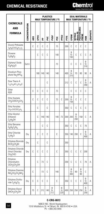
NIBCO INC. World Headquarters 1516 Middlebury St. • Elkhart, IN 46516-4740 • USA
Ph: 1.800.343.5455
www.chemtrol.com
54
chEMicals
and
FoRMUla
con
cEn
tRat
ion
plastics Max tEMpERatURE (°F)
sEal MatERials Max tEMpERatURE (°F)
ab
s
cp
Vc
pp
pV
c
pV
dF
pEx
pp
sU
ptF
E
Epd
M
nit
Ril
E (b
una-
n)
po
lYc
hlo
Ro
-p
REn
E
FkM
gR
ap
hit
E
Dioctyl Phthalate C6H4(COOC8H17)2
C C C C 73 200 C C C C
Dioxane C4H8O2
C C C 140B to
160C C C A
Diphenyl Oxide (C6H5)2O Sat'd. 73 C C C
B to
310
Disodium Phos-phate Na2HPO4 180 140 140 140 400
B to
21070 80 90 A
Dow Therm AC12H10•C12H10O
C 212 C C CB to
350A
Ether ROR C C C C 73 C C C C
Ethyl Acetate CH3COOCH2CH3
C C C C 73 C 200B to
158C C C
Ethyl Acrylate CH2=CHCOOC2H5
C C 350 C C C C
Ethyl Alcohol (Ethanol) C2H5OH
C 140 140 140 73 300 200B to
200158 C A
Ethyl Benzene C6H5C2H5
C C 350 C C C 70
Ethyl Chloride C2H5CI Dry C C C C 350 140 200 C
B to
400A
Ethylene Bromide BrCH2CH2Br Dry C C 350
Ethylene Chloride (Vinyl Chloride) CH2CHCl
Dry C C C C C 350 C C C 200
Ethylene Chlorohydrin CICH2CH2OH
C 73 C 200 C C C 70 A
Ethylene Diamine NH2CH2CH2NH2 C 73 C 140
B to
30080
B to 90
C
Ethylene Dichlo-ride C2H4CI2 Dry C C C C C 350 C C C
B to
400A
Ethylene Glycol OHCH2CH2OH 73 C 212 140
B to
212
B to
220400 250 250 250
B to
250A
chEMical REsistancE
c-cRg-0613
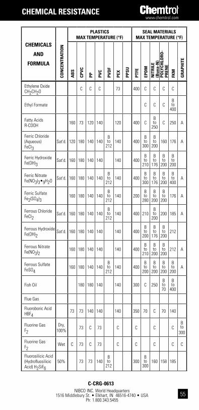
www.chemtrol.com
NIBCO INC. World Headquarters 1516 Middlebury St. • Elkhart, IN 46516-4740 • USA
Ph: 1.800.343.545555
chEMicals
and
FoRMUla co
ncE
ntR
atio
n
plastics Max tEMpERatURE (°F)
sEal MatERials Max tEMpERatURE (°F)
ab
s
cp
Vc
pp
pV
c
pV
dF
pEx
pp
sU
ptF
E
Epd
M
nit
Ril
E (b
una-
n)
po
lYc
hlo
Ro
-p
REn
E
FkM
gR
ap
hit
E
Ethylene Oxide CH2CH2O C C C 73 400 C C C C
Ethyl Formate C C CB to
400
Fatty Acids R-COOH 160 73 120 140 120 400 C
B to
250C 250 A
Ferric Chloride (Aqueous) FeCI3
Sat'd. 120 180 140 140B to
212140 400
B to
300
B to
200160 176 A
Ferric Hydroxide Fe(OH)3 Sat'd. 160 180 140 140 140 400
B to
210
B to
176
B to
200
B to
200
Ferric Nitrate Fe(NO3)3•9H2O Sat'd. 160 180 140 140
B to
212140 400
B to
300
B to
176
B to
200
B to
400A
Ferric Sulfate Fe2(SO4)3 160 180 140 140
B to
212140 200
B to
280
B to
200
B to
200176 A
Ferrous Chloride FeCI2 Sat'd. 160 180 140 140
B to
212140 400 210
B to
200200 185 A
Ferrous Hydroxide Fe(OH)2 Sat'd. 160 180 140 140 140 400
B to
200
B to
176
B to
200212
Ferrous Nitrate Fe(NO3)2 160 180 140 140 140 400
B to
210
B to
200
B to
200212 A
Ferrous Sulfate FeSO4 160 180 140 140
B to
212140 400
B to
200
B to
200
B to
200
B to
200A
Fish Oil 180 180 140 140 300 C 250B to 70
B to
400
Flue Gas
Fluoroboric Acid HBF4 73 73 140 140 140 350 70 C 70 140
Fluorine Gas F2
Dry, 100% 73 C 73 C C C C
B to
300
Fluorine Gas F2
Wet C 73 C 73 C C C C C
Fluorosilicic Acid (Hydrofluosilicic Acid) H2SiF6
50% 73 73 140B to
212300
B to
300160 158 185
chEMical REsistancE
c-cRg-0613

NIBCO INC. World Headquarters 1516 Middlebury St. • Elkhart, IN 46516-4740 • USA
Ph: 1.800.343.5455
www.chemtrol.com
56
chEMicals
and
FoRMUla
con
cEn
tRat
ion
plastics Max tEMpERatURE (°F)
sEal MatERials Max tEMpERatURE (°F)
ab
s
cp
Vc
pp
pV
c
pV
dF
pEx
pp
sU
ptF
E
Epd
M
nit
Ril
E (b
una-
n)
po
lYc
hlo
Ro
-p
REn
E
FkM
gR
ap
hit
E
Formaldehyde HCHO Dilute 160 73 140 140
B to
176300 212 140 150 C A
Formaldehyde HCHO 35% 160 C 140 140
B to
212140 100 300 212 140 150 C A
Formaldehyde HCHO 50% C 140 140 300
B to
140C
B to 70
C A
Formic Acid HCOOH C C 140 73 B 140 300 210 C B B A
Freon 11 CCI3F 100% C 73 C 140 73 300 C
B to
250C C A
Freon 12 CCI2F2 100% 73 73 140 73 C B B B C A
Freon 21 CHCI2F 100% C C C 300 C C C C A
Freon 22 CHCIF2 100% 73 73 C C C 140 C 250 C A
Freon 113 C2CI2F3 100% C 140 73 300 C B B C A
Freon 114 C2CI2F4 100% C 140 73 300 B B B C A
Fructose C6H12O6 Sat'd. 73 180 180 140 140 300
Furfural C4H3OCHO C C C C C 300
B to
160C C C
Gallic Acid C6H2(OH)3CO2H•H2O
73 140 73 300 C C CB to
400
Gasoline (Leaded) C C C B 73 200 C 190 C 250 A
Gasoline (Unleaded) C C C B 73 200 C C 190 A
Gasohol C C C B 73 200 A
Gasoline (Sour) C C C B C 200 C 250 C
B to
250A
Gelatin 180 180 140 140 300 200 200 200 212
Glauber’s Salt 200B to
200C
B to
200
B to
400
chEMical REsistancE
c-cRg-0613
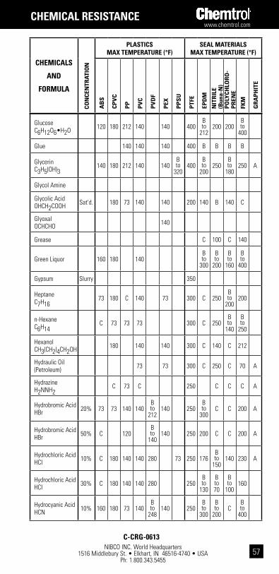
www.chemtrol.com
NIBCO INC. World Headquarters 1516 Middlebury St. • Elkhart, IN 46516-4740 • USA
Ph: 1.800.343.545557
chEMicals
and
FoRMUla co
ncE
ntR
atio
n
plastics Max tEMpERatURE (°F)
sEal MatERials Max tEMpERatURE (°F)
ab
s
cp
Vc
pp
pV
c
pV
dF
pEx
pp
sU
ptF
E
Epd
M
nit
Ril
E (b
una-
n)
po
lYc
hlo
Ro
-p
REn
E
FkM
gR
ap
hit
E
Glucose C6H12O6•H2O 120 180 212 140 140 400
B to
212200 200
B to
400
Glue 140 140 140 400 B B B B
Glycerin C3H5(OH)3 140 180 212 140 140
B to
320400
B to
200250
B to
180250 A
Glycol Amine
Glycolic Acid OHCH2COOH Sat'd. 180 73 140 140 200 140 B 140 C
Glyoxal OCHCHO 140
Grease C 100 C 140
Green Liquor 160 180 140B to
300
B to
200
B to
160
B to
400
Gypsum Slurry 350
Heptane C7H16 73 180 C 140 73 300 C 250
B to
200200
n-Hexane C6H14 C 73 73 73 300 C 250
B to
140
B to
250
Hexanol CH3(CH2)4CH2OH 180 140 140 300 C 140 C 212
Hydraulic Oil (Petroleum) 73 73 300 C 250 C 70 A
Hydrazine H2NNH2 C 73 C 250 C C C A
Hydrobromic Acid HBr 20% 73 73 140 140
B to
212140 250
B to
300C C 200 A
Hydrobromic Acid HBr 50% C 120
B to
140140 250 200 C C 200 A
Hydrochloric Acid HCI 10% C 180 140 140 280 73 250 176
B to
150140 230 A
Hydrochloric Acid HCI 30% C 180 140 140 280 250
B to
130
B to 70
B to
100160
Hydrocyanic Acid HCN 10% 160 180 73 140
B to
248140 250
B to
300
B to
200C
B to
400
chEMical REsistancE
c-cRg-0613
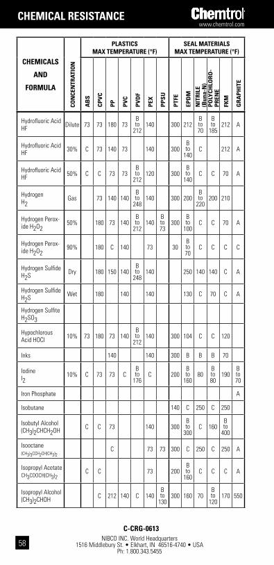
NIBCO INC. World Headquarters 1516 Middlebury St. • Elkhart, IN 46516-4740 • USA
Ph: 1.800.343.5455
www.chemtrol.com
58
chEMicals
and
FoRMUla
con
cEn
tRat
ion
plastics Max tEMpERatURE (°F)
sEal MatERials Max tEMpERatURE (°F)
ab
s
cp
Vc
pp
pV
c
pV
dF
pEx
pp
sU
ptF
E
Epd
M
nit
Ril
E (b
una-
n)
po
lYc
hlo
Ro
-p
REn
E
FkM
gR
ap
hit
E
Hydrofluoric Acid HF Dilute 73 73 180 73
B to
212140 300 212
B to 70
B to
185212 A
Hydrofluoric Acid HF 30% C 73 140 73 140 300
B to
140C 212 A
Hydrofluoric Acid HF 50% C C 73 73
B to
212120 300
B to
140C C 70 A
Hydrogen H2 Gas 73 140 140
B to
248140 300 200
B to
220200 210
Hydrogen Perox-ide H2O2 50% 180 73 140
B to
212140
B to 73
300B to
100C C 70 A
Hydrogen Perox-ide H2O2 90% 180 C 140 73 30
B to 70
C C C C
Hydrogen Sulfide H2S Dry 180 150 140
B to
248140 250 140 140 C A
Hydrogen Sulfide H2S Wet 180 140 140 130 C 70 C A
Hydrogen Sulfite H2SO3
Hypochlorous Acid HOCI 10% 73 180 73 140
B to
212140 300 104 C C 120
Inks 140 140 300 B B B 70
Iodine I2 10% C 73 73 C
B to
176C 200
B to
16080
B to 80
190B to 70
Iron Phosphate A
Isobutane 140 C 250 C 250
Isobutyl Alcohol (CH3)2CHCH2OH C C 73 140 300
B to
300C 160
B to
400
Isooctane (CH3)3CCH2CH(CH3)2
C 73 73 300 C 250 C 250 A
Isopropyl Acetate CH3COOCH(CH3)2
C C 73 200B to
160C C C A
Isopropyl Alcohol (CH3)2CHOH C 212 140 C 140
B to
130300 160 70
B to
120170 550
chEMical REsistancE
c-cRg-0613

www.chemtrol.com
NIBCO INC. World Headquarters 1516 Middlebury St. • Elkhart, IN 46516-4740 • USA
Ph: 1.800.343.545559
chEMicals
and
FoRMUla co
ncE
ntR
atio
n
plastics Max tEMpERatURE (°F)
sEal MatERials Max tEMpERatURE (°F)
ab
s
cp
Vc
pp
pV
c
pV
dF
pEx
pp
sU
ptF
E
Epd
M
nit
Ril
E (b
una-
n)
po
lYc
hlo
Ro
-p
REn
E
FkM
gR
ap
hit
E
Isopropyl Ether (CH3)2CHOCH(CH3)2
C C C 73 140 C C C C
JP-3 Fuel 200 C 70 C 140
JP-4 Fuel C C B 73 300 C 250 CB to
400
JP-5 Fuel C C B 73 300 C 250 CB to
400
JP-6 Fuel 200 CB to
120C 70
Kelp Slurry
Kerosene 73 B C B C 250 C 250 CB to
400A
Ketchup 73 250 210 200 70 200
Ketones C C C C 73 200 200 200 C C A
Kraft Liquors 73 180 140 120 250
Lactic Acid CH3CHOHCOOH 25% 73 180 212 140 140 300 212 80 70
B to
400A
Lactic Acid CH3CHOHCOOH 80% C C 140 73 140 300 176 80 70
B to
400A
Lard OIl C 140 C 300
Latex 140 140 200B to
200200 160 160
Lauric Acid CH3(CH2)10COOH 180 140 140 120 300 C 70 70 70
Lauryl Chloride CH3(CH2)10CH2Cl
73 140B to
248120 300
Lead Acetate Pb(CH3COO)2•3H2O
Sat'd. 180 180 140B to
212140 300 200
B to
140
B to
140C
Lead Chloride PbCI2 180 140 140 120 300 176 140 C 212 A
Lead Nitrate Pb(NO3)2 Sat'd. 180 140 140 120 300
B to
300
B to
220200 212 A
chEMical REsistancE
c-cRg-0613

NIBCO INC. World Headquarters 1516 Middlebury St. • Elkhart, IN 46516-4740 • USA
Ph: 1.800.343.5455
www.chemtrol.com
60
chEMicals
and
FoRMUla
con
cEn
tRat
ion
plastics Max tEMpERatURE (°F)
sEal MatERials Max tEMpERatURE (°F)
ab
s
cp
Vc
pp
pV
c
pV
dF
pEx
pp
sU
ptF
E
Epd
M
nit
Ril
E (b
una-
n)
po
lYc
hlo
Ro
-p
REn
E
FkM
gR
ap
hit
E
Lead Sulfate PbSO4 180 140 140 120 300
B to
210120
B to
180212 A
Lemon Oil C CB to 73
300 C 70 C 70
Lime Sulfur 73 73 73 120B to
300
B to
220
B to
180
B to
420
Linoleic Acid 180 180 140 300 C C C C
Linseed Oil 73 C 140 140B to
248
B to 73
300 C 200B to
180250
Lithium Bromide LiBr 140 140 140
B to
212300 A
Lithium Chloride LiCI 140 140 120 160 160 160 160 A
Lithium Hydroxide LiOH 140 120 160 C 70 C
Lubricating Oil (ASTM #1) 180 C 140
B to
24873 350 C 180 150 70
Lubricating Oil (ASTM #2) 180 C 140 73 350 C
B to
180C 70 -
300
Lubricating Oil (ASTM #3) 180 C 140 73 350 C 180 C 350
Ludox
Magnesium Car-bonate MgCO3
120 180 212 140B to
212140 225
B to
300140
B to
180212
Magnesium Chloride MgCI2 Sat'd. 120 180 140 140
B to
140140 400 230 176
B to
200185 A
Magnesium Citrate MgHC6H5O7•5H2O
180 140 140 300 176 140 212
Magnesium Oxide MgO 160
Magnesium Sulfate MgSO4•7H2O
160 180 212 140B to
212140 300 194
B to
230
B to
200
B to
390A
Maleic Acid HOOCCH=CHCOOH
Sat'd. 160 180 140 140B to
140140 250 C C 140 A
chEMical REsistancE
c-cRg-0613
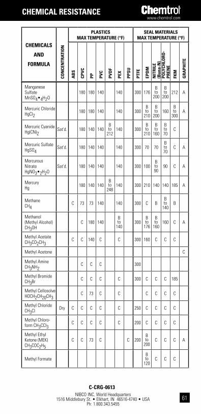
www.chemtrol.com
NIBCO INC. World Headquarters 1516 Middlebury St. • Elkhart, IN 46516-4740 • USA
Ph: 1.800.343.545561
chEMicals
and
FoRMUla co
ncE
ntR
atio
n
plastics Max tEMpERatURE (°F)
sEal MatERials Max tEMpERatURE (°F)
ab
s
cp
Vc
pp
pV
c
pV
dF
pEx
pp
sU
ptF
E
Epd
M
nit
Ril
E (b
una-
n)
po
lYc
hlo
Ro
-p
REn
E
FkM
gR
ap
hit
E
Manganese Sulfate MnSO4•4H2O
180 180 140 140 300 176B to
200
B to
200212 A
Mercuric Chloride HgCI2 180 180 140 140 300
B to
210
B to
200160
B to
300A
Mercuric Cyanide Hg(CN)2 Sat'd. 180 140 140
B to
212140 300
B to
210
B to
160
B to 70
C
Mercuric Sulfate HgSO4 Sat'd. 180 140 140 140 300 70 70
B to 70
C A
Mercurous Nitrate HgNO3•2H2O
Sat'd. 180 140 140 140 300 100B to 90
90 C A
Mercury Hg 180 140 140
B to
248140 300 210 140 140 185 A
Methane CH4 C 73 73 140 140 300 C B
B to
140B
Methanol (Methyl Alcohol) CH3OH
C 180 140B to
140300
B to
176
B to
160160 C A
Methyl Acetate CH3CO2CH3 C C 140 C C 300 160 C C C
Methyl Acetone C
Methyl Amine CH3NH2 C C C 300
Methyl Bromide CH3Br C C C C 300 C C C 185
Methyl Cellosolve HOCH2CH20CH3 C 73 C C C C C C
Methyl Chloride CH3CI Dry C C C C C 250 C C C C
Methyl Chloro-form CH3CCI3
C C C C C 200 C C C C
Methyl Ethyl Ketone (MEK) CH3COC2H5
C C 73 C C 200B to
200C C C A
Methyl FormateB to
120C C C
chEMical REsistancE
c-cRg-0613
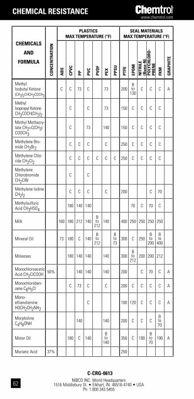
NIBCO INC. World Headquarters 1516 Middlebury St. • Elkhart, IN 46516-4740 • USA
Ph: 1.800.343.5455
www.chemtrol.com
62
chEMicals
and
FoRMUla
con
cEn
tRat
ion
plastics Max tEMpERatURE (°F)
sEal MatERials Max tEMpERatURE (°F)
ab
s
cp
Vc
pp
pV
c
pV
dF
pEx
pp
sU
ptF
E
Epd
M
nit
Ril
E (b
una-
n)
po
lYc
hlo
Ro
-p
REn
E
FkM
gR
ap
hit
E
Methyl Isobutyl Ketone (CH3)2CHCH2COCH3
C C 73 C 73 200B to
130C C C A
Methyl Isopropyl Ketone CH3COCH(CH3)2
C C 73 150 C C C C
Methyl Methacry-late CH2=C(CH3)COOCH3
C 73 140 150 C C C C
Methylene Bro-mide CH2Br2 C C C C 250 C C C C
Methylene Chlo-ride CH2CI2 C C C C C C 250 C C C C
Methylene Chlorobromide CH2CIBr
C C
Methylene Iodine CH2I2 C C C C 200 C 70
Methylsulfuric Acid CH3HSO4 180 140 140 70 C 70 C
Milk 160 180 212 140B to
212140 400 250 250 250 250
Mineral Oil 73 180 C 140B to
212
B to 73
300 C 250B to
200
B to
400
Molasses 180 140 140 140 300B to
212200 200 212
Monochloroacetic Acid CH2CICOOH 50% 140 140 140 200 C 70 C A
Monochloroben-zene C6H5CI C 73 C C 200 C C C C A
Mono-ethanolamine HOCH2CH2NH2
C 100 120 C C C A
Morpholine C4H8ONH 140 140 200 C C C
B to 70
Motor Oil 180 C 140B to
140350 C 190
B to 70
190 A
Muriatic Acid 37% 250
chEMical REsistancE
c-cRg-0613

www.chemtrol.com
NIBCO INC. World Headquarters 1516 Middlebury St. • Elkhart, IN 46516-4740 • USA
Ph: 1.800.343.545563
chEMicals
and
FoRMUla co
ncE
ntR
atio
n
plastics Max tEMpERatURE (°F)
sEal MatERials Max tEMpERatURE (°F)
ab
s
cp
Vc
pp
pV
c
pV
dF
pEx
pp
sU
ptF
E
Epd
M
nit
Ril
E (b
una-
n)
po
lYc
hlo
Ro
-p
REn
E
FkM
gR
ap
hit
E
Naphtha 73 73 140B to
122200 C
B to
250C
B to
400
Naphthalene C10H8 C 73 C 73 250 C C C 176
Natural Gas 73 73 140 140 300 C 250 140 250
Nickel Ammo-nium Sulfate 250 70 70 70
B to 70
Nickel Chloride NiCI2 Sat'd. 160 180 180 140
B to
212140 406 176 176
B to
200
B to
400A
Nickel Nitrate Ni(NO3)2•6H2O Sat'd. 160 180 180 140
B to
248140 400 212
B to
200
B to
200248 A
Nickel Sulfate NiSO4 Sat'd. 160 180 180 140
B to
212140 400 176 176 160
B to
400A
Nicotine C10H14N2 180 140 140 C C C
Nicotinic Acid C5H4NCOOH 180 140
B to
212140
B to
14070
B to
200
Nitric Acid HNO3 <10% C 180 180 140
B to
212250
B to
104C C
B to
185A
Nitric Acid HNO3 30% C
B to
130140 140
B to
212250 C C
B to
185C
Nitric Acid HNO3 40% C
B to
12073 140 250 C C C 70 C
Nitric Acid HNO3 50% C 110 C 100 250 C C C 70 C
Nitric Acid HNO3 70% C 100 C 73 250 C C C C C
Nitric Acid Fum-ing 70 C C C C C
Nitrobenzene C6H5NO2 C C C C
B to
122C 400 C C C C A
Nitrogen N2 Gas 300
B to
350
B to
230300
B to
400A
Nitroglyc-erin CH2NO3CH-NO3CH2NO3
C 73B to 73
70 70 C 70 C
chEMical REsistancE
c-cRg-0613
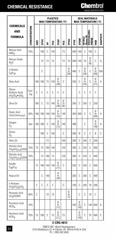
NIBCO INC. World Headquarters 1516 Middlebury St. • Elkhart, IN 46516-4740 • USA
Ph: 1.800.343.5455
www.chemtrol.com
64
chEMicals
and
FoRMUla
con
cEn
tRat
ion
plastics Max tEMpERatURE (°F)
sEal MatERials Max tEMpERatURE (°F)
ab
s
cp
Vc
pp
pV
c
pV
dF
pEx
pp
sU
ptF
E
Epd
M
nit
Ril
E (b
una-
n)
po
lYc
hlo
Ro
-p
REn
E
FkM
gR
ap
hit
E
Nitrous Acid HNO2 10% 180 C 140 73 400 100 C 100 C
Nitrous Oxide N2O 73 73 73 73 73 400 140 70
B to 80
C A
n-Octane C8H18 C
B to
250400 C
B to
200C
B to
400550
Oleic Acid 160 180 73 140B to
248C 250 C
B to
225C
B to
212A
Oleum (Sulfuric Acid) xH2SO4•yS03
Fum-ing C C C C C C C C C C
Olive Oil 160 C 73 140B to
248
B to 68
350 C 250 C 250
Oxalic Acid HOOCCOOH•2H2O
50% 160 180 140 140B to
122140 300 300 C C
B to
400A
Oxygen O2 Gas 160 180 C 140
B to
212140 406 C
B to
190A
Ozone O3 180 C 140 C 300 B C C B C
Palm Oil 73 140 200 C 250 C 250
Palmitic Acid CH3(CH2)14COOH 10% 73 73 180 140 120 300 C 220 C 400
Palmitic Acid CH3(CH2)14COOH 70% 73 180 73 120 300 C 220 C 400
Parafin C36H74 73 180 140 140
B to
212C 250 C 250 C 400
Peanut Oil C 140B to
248250 C 250 C 400
n-Pentane CH3(CH2)3CH3 C C C C C 100 C 250 70 200
Peracetic Acid CH3COOOH 40% C 73 73
B to 73
C C 70 C
Perchloric Acid HCIO4 10%
B to
212250
B to
140C 140 400 A
Perchloric Acid HCIO4 70% 73 180 C 73
B to
21273
B to
140C 70 400 C
chEMical REsistancE
c-cRg-0613
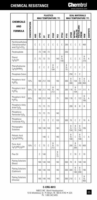
www.chemtrol.com
NIBCO INC. World Headquarters 1516 Middlebury St. • Elkhart, IN 46516-4740 • USA
Ph: 1.800.343.545565
chEMicals
and
FoRMUla co
ncE
ntR
atio
n
plastics Max tEMpERatURE (°F)
sEal MatERials Max tEMpERatURE (°F)
ab
s
cp
Vc
pp
pV
c
pV
dF
pEx
pp
sU
ptF
E
Epd
M
nit
Ril
E (b
una-
n)
po
lYc
hlo
Ro
-p
REn
E
FkM
gR
ap
hit
E
Perchloroethylene (Tetrachloroethyl-ene) CI2C=CCI2
C C C C C C C 200 C C C 400
Perphosphate 73 140 73 250
Phenol C6H5OH C 73 73 73 140
B to
140C C C
B to
210A
Phenylhydrazine C6H5NHNH2 C C C
B to
104C
B to 70
C C C C
Phosphate Esters 250 C C
Phosphoric Acid H3PO4 10% 180 212 140 140 300
B to
300104
B to
206
B to
400A
Phosphoric Acid H3PO4 50% 73 180 212 140
B to
212140 300 176
B to
104171 212 A
Phosphoric Acid H3PO4 85% 180 212 140 73 300 176 C 122
B to
185A
Phosphoric Anhy-dride P2O5 73 73 73 200 B B B
Phosphorus Pentoxide P2O5 73 73 73 140
Phosphorus Trichloride PCI3 C 73 C C 120 300 70 C C 70 A
Photographic Solutions 180 140 140 140
B to
104
B to 70
B to
140185
Phthalic Acid C6H4(COOH)2 140 C 140
B to
100C
B to
100C A
Picric Acid C6H2(NO2)3OH 10% C C 73 C
B to
21273 200
B to
20070 400
Pine Oil C 140B to 73
C 70 C 70
Plating Solutions (Brass) 180 140 140 140 300 70 B 140 140
Plating Solutions (Cadmium) 180 140 140 140 300 300
B to
180
B to
200190
Plating Solutions (Chrome) 180 140 140 140 300 210 C C
B to
400
chEMical REsistancE
c-cRg-0613
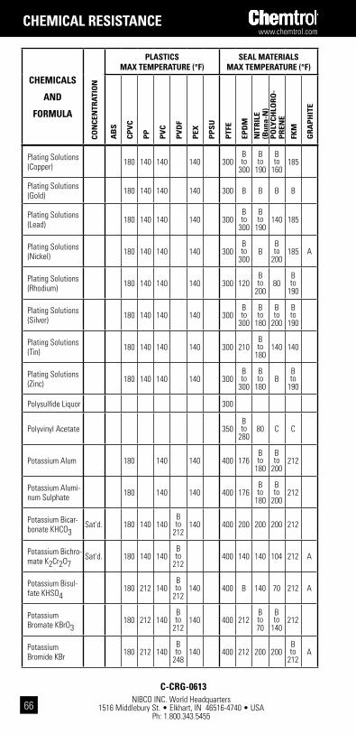
NIBCO INC. World Headquarters 1516 Middlebury St. • Elkhart, IN 46516-4740 • USA
Ph: 1.800.343.5455
www.chemtrol.com
66
chEMicals
and
FoRMUla
con
cEn
tRat
ion
plastics Max tEMpERatURE (°F)
sEal MatERials Max tEMpERatURE (°F)
ab
s
cp
Vc
pp
pV
c
pV
dF
pEx
pp
sU
ptF
E
Epd
M
nit
Ril
E (b
una-
n)
po
lYc
hlo
Ro
-p
REn
E
FkM
gR
ap
hit
E
Plating Solutions (Copper) 180 140 140 140 300
B to
300
B to
190
B to
160185
Plating Solutions (Gold) 180 140 140 140 300 B B B B
Plating Solutions (Lead) 180 140 140 140 300
B to
300
B to
190140 185
Plating Solutions (Nickel) 180 140 140 140 300
B to
300B
B to
200185 A
Plating Solutions (Rhodium) 180 140 140 140 300 120
B to
20080
B to
190
Plating Solutions (Silver) 180 140 140 140 300
B to
300
B to
180
B to
200
B to
190
Plating Solutions (Tin) 180 140 140 140 300 210
B to
180140 140
Plating Solutions (Zinc) 180 140 140 140 300
B to
300
B to
180B
B to
190
Polysulfide Liquor 300
Polyvinyl Acetate 350B to
28080 C C
Potassium Alum 180 140 140 400 176B to
180
B to
200212
Potassium Alumi-num Sulphate 180 140 140 400 176
B to
180
B to
200212
Potassium Bicar-bonate KHCO3 Sat'd. 180 140 140
B to
212140 400 200 200 200 212
Potassium Bichro-mate K2Cr2O7 Sat'd. 180 140 140
B to
212400 140 140 104 212 A
Potassium Bisul-fate KHSO4 180 212 140
B to
212140 400 B 140 70 212 A
Potassium Bromate KBrO3 180 212 140
B to
212140 400 212
B to 70
B to
140212
Potassium Bromide KBr 180 212 140
B to
248140 400 212 200 200
B to
212A
chEMical REsistancE
c-cRg-0613
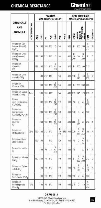
www.chemtrol.com
NIBCO INC. World Headquarters 1516 Middlebury St. • Elkhart, IN 46516-4740 • USA
Ph: 1.800.343.545567
chEMicals
and
FoRMUla co
ncE
ntR
atio
n
plastics Max tEMpERatURE (°F)
sEal MatERials Max tEMpERatURE (°F)
ab
s
cp
Vc
pp
pV
c
pV
dF
pEx
pp
sU
ptF
E
Epd
M
nit
Ril
E (b
una-
n)
po
lYc
hlo
Ro
-p
REn
E
FkM
gR
ap
hit
E
Potassium Car-bonate (Potash) K2CO3
73 180 180 140 C 140 400 B 200 200B to
212A
Potassium Chlo-rate (Aqueous) KClO3
160 180 212 140 C 140 400B to
20070
B to
200B C
Potassium Chloride KCl
160 180 212 140B to
212140 400 B 200 200 212
Potassium Chro-mate K2CrO4 180 212 140 140 400 176
B to
140140
B to
212C
Potassium Cyanide KCN 180 180 140
B to
212140 400 B 200 200 200
Potassium Dichro-mate K2Cr2O7 Sat'd. 180 180 140 140 400 212 140 120 212 C
Potas-sium Ferricyanide K3Fe(CN)6
180 180 140B to
248140 400 70 C 70
B to
212
Potassium Ferrocyanide K4Fe(CN)6•3H2O
180 180 140B to
248140 400 140 C 70 140
Potassium Fluoride KF
180 180 140B to
212140 400 200
B to
18070 212 A
Potassium Hydroxide KOH 25% 160 180 212 140
B to
140248 300 320
B to 80
B to
21280 A
Potassium Hypo-chlorite KCIO 160 180 140 120 400 70 C
B to 70
C
Potassium Iodide KI 180 73 73
B to
212140 400 70 70 B A
Potassium Nitrate KNO3 160 180 140 140 140 400 B
B to
200
B to
200212 C
Potassium Perbo-rate KBO3 180 140 140 140 400 70
B to 70
70B to 70
A
Potassium Perchlorate KCIO4 180 140 140 140 200 140 C 70 190
Potassium Permanganate KMnO4
10% 180 73 140 140 400 210 C 140B to
212
chEMical REsistancE
c-cRg-0613
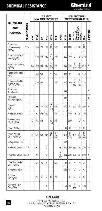
NIBCO INC. World Headquarters 1516 Middlebury St. • Elkhart, IN 46516-4740 • USA
Ph: 1.800.343.5455
www.chemtrol.com
68
chEMicals
and
FoRMUla
con
cEn
tRat
ion
plastics Max tEMpERatURE (°F)
sEal MatERials Max tEMpERatURE (°F)
ab
s
cp
Vc
pp
pV
c
pV
dF
pEx
pp
sU
ptF
E
Epd
M
nit
Ril
E (b
una-
n)
po
lYc
hlo
Ro
-p
REn
E
FkM
gR
ap
hit
E
Potassium Permanganate KMnO4
25% 180 73 73B to
212140 400 200 C 140
B to
212
Potassium Persul-fate K2S2O8 180 140 140
B to
176140 400 180 C B 210
Potassium Sulfate K2SO4 160 180 180 140
B to
212140 200 176
B to
200
B to
200212 A
Potassium Sulfide K2S 180 140 68 140 300 70 70 210
Potassium Sulfite K2SO3•2H2O 180 140 140 300 200
B to
150
B to
150210
Potassium Tetraborate 400 A
Potassium Tripolyphosphate 300 A
Propane C3H8 73 73 140
B to
248140 300 C 250 140 250 A
Propargyl Alcohol C 140 140 140 140 70 70 140
Propionic Acid CH3CH2CO2H C C 140
B to
140140 200 C C
Propyl Acetate 140 C C C C
Propyl Alcohol CH3CH2CH2OH 73 C 140 140
B to
122
B to
140350
B to
225180
B to
176
B to
300
n-Propyl Bromide 300
Propylene Glycol <25% C C 180 300 200 180 70 250 A
Propylene Glycol >25% C CB to
180300 200 180 70 250 A
Propylene Oxide CH3CHCH2O C 73 C 140 150 C C C C
n-Propyl Nitrate 200 C C C C
Pyridine N(CH)4CH C C C
B to 68
73 C C C C
Pyrogallic Acid C6H3(OH)3 73 150 C
B to
100C 140
chEMical REsistancE
c-cRg-0613
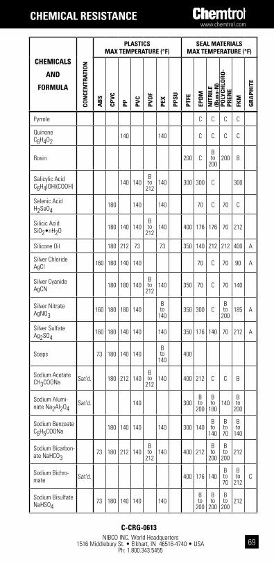
www.chemtrol.com
NIBCO INC. World Headquarters 1516 Middlebury St. • Elkhart, IN 46516-4740 • USA
Ph: 1.800.343.545569
chEMicals
and
FoRMUla co
ncE
ntR
atio
n
plastics Max tEMpERatURE (°F)
sEal MatERials Max tEMpERatURE (°F)
ab
s
cp
Vc
pp
pV
c
pV
dF
pEx
pp
sU
ptF
E
Epd
M
nit
Ril
E (b
una-
n)
po
lYc
hlo
Ro
-p
REn
E
FkM
gR
ap
hit
E
Pyrrole C C C C
Quinone C6H4O2 140 140 C C C C
Rosin 200 CB to
200200 B
Salicylic Acid C6H4(OH)(COOH) 140 140
B to
212140 300 300 C 300
Selenic Acid H2SeO4 180 140 140 70 C 70 C
Silicic Acid SiO2•nH2O 180 140 140
B to
212140 400 176 176 70 212
Silicone Oil 180 212 73 73 350 140 212 212 400 A
Silver Chloride AgCI 160 180 140 140 70 C 70 90 A
Silver Cyanide AgCN 180 180 140
B to
212140 350 70 C 70 140
Silver Nitrate AgNO3 160 180 180 140
B to
140350 300 C
B to
200185 A
Silver Sulfate Ag2SO4 160 180 140 140 140 350 176 140 70 212 A
Soaps 73 180 140 140B to
140400
Sodium Acetate CH3COONa Sat'd. 180 212 140
B to
212140 400 212 C C B
Sodium Alumi-nate Na2AI2O4 Sat'd. 140 300
B to
200
B to
180140
B to
200
Sodium Benzoate C6H5COONa 180 140 140 140 300 140
B to
140
B to 70
B to
140
Sodium Bicarbon-ate NaHCO3 73 180 212 140
B to
212140 400 212
B to
200
B to
200212
Sodium Bichro-mate Sat'd. 400 176 140
B to 70
B to
212C
Sodium Bisulfate NaHSO4 73 180 140 140 140
B to
200
B to
200
B to
200212
chEMical REsistancE
c-cRg-0613

NIBCO INC. World Headquarters 1516 Middlebury St. • Elkhart, IN 46516-4740 • USA
Ph: 1.800.343.5455
www.chemtrol.com
70
chEMicals
and
FoRMUla
con
cEn
tRat
ion
plastics Max tEMpERatURE (°F)
sEal MatERials Max tEMpERatURE (°F)
ab
s
cp
Vc
pp
pV
c
pV
dF
pEx
pp
sU
ptF
E
Epd
M
nit
Ril
E (b
una-
n)
po
lYc
hlo
Ro
-p
REn
E
FkM
gR
ap
hit
E
Sodium Bisulfite NaHSO3 180 140 140 140 400 176 160
B to
200212
Sodium Borate (Borax) Na2B4O7•10H2O
Sat'd. 160 180 180 140 140 300B to
300
B to
220
B to
200210 A
Sodium Bromide NaBr Sat'd. 120 180 140 140 140 300 140 C 70
B to
180A
Sodium Carbon-ate Na2CO3 73 180 212 140 C 140
B to 73
400 176B to
200
B to
200212
Sodium Chlorate NaCIO3 Sat'd. 180 140 73 C 140 350
B to
200
B to
200
B to
200
B to
200
Sodium Chloride NaCI 120 180 212 140 140 350
B to
212160 120 212
Sodium Chlorite NaCIO2 25% 180 73 C 140 200 70 C
B to
140C
Sodium Chromate Na2CrO4•4H2O 120 180 140
B to
176140 140 140 70 140 C
Sodium Cyanide NaCN 180 180 140
B to
212140 350 176
B to
230140 176 200
Sodium Dichromate Na2Cr2O7•2H2O
20% 180 180 140 140 300 176 140 CB to
212C
Sodium Ferricyanide Na3Fe(CN)6•2H2O
Sat'd. 180 140 140 140 350 300 70 70 140
Sodium Ferrocyanide Na3Fe(CN)6•10H2O
Sat'd. 180 140 140 140 350 140 80 70 140
Sodium Fluoride NaF 120 180 180 140
B to
212140 350 140 100 140 140 A
Sodium Hydroxide NaOH <5%
B to 68
Sodium Hydroxide NaOH <10% 400
B to
200212
B to
200
B to
140A
Sodium Hydroxide NaOH 30% 120 180 212 140 C
B to
140350
B to
130212
B to
20080 A
chEMical REsistancE
c-cRg-0613

www.chemtrol.com
NIBCO INC. World Headquarters 1516 Middlebury St. • Elkhart, IN 46516-4740 • USA
Ph: 1.800.343.545571
chEMicals
and
FoRMUla co
ncE
ntR
atio
n
plastics Max tEMpERatURE (°F)
sEal MatERials Max tEMpERatURE (°F)
ab
s
cp
Vc
pp
pV
c
pV
dF
pEx
pp
sU
ptF
E
Epd
M
nit
Ril
E (b
una-
n)
po
lYc
hlo
Ro
-p
REn
E
FkM
gR
ap
hit
E
Sodium Hydroxide NaOH 50% 120 180 212 140
B to
140194 350
B to
130212
B to
200
B to 70
A
Sodium Hydroxide NaOH 70% 120 180 212 140
B to
140350
B to
130
B to 70
B to
200
B to 70
A
Sodium Hypochlo-rite NaOCI•5H2O 120 180 73 140
B to
200140
B to
190350 C C C
B to
130
Sodium Metaphosphate (NaPO3)n
180 120 140 300 220 150B to
400A
Sodium Nitrate NaNO3 Sat'd. 160 180 180 140
B to
212140 400 200
B to
171
B to
200212 A
Sodium Nitrite NaNO2 160 180 73 140
B to
212140 400 176 171
B to
140212
Sodium Perborate NaBO3•4H2O 120 180 73 140 73 350 140 C B 140 A
Sodium Perchlo-rate NaCIO4 180 212 140 140 350 70 C 70 C
Sodium Peroxide Na2O2 10% 180 140 140 250 300 C C 400 C
Sodium Phos-phate NaH2PO4 Acid 120 180 212 140
B to
140140 400 A
Sodium Phos-phate NaH2PO4
Alka-line 120 180 212 140 400 A
Sodium Phos-phate NaH2PO4
Neu-tral 120 180 212 400 A
Sodium Silicate 180 140 140 140B to
200140
B to
200212
Sodium Sulfate Na2SO4 Sat'd. 160 180 212 140 400
B to
200200
B to
200212 A
Sodium Sulfide Na2S Sat'd. 160 180 212 140 140 350 200
B to
200
B to
200176
Sodium Sulfite Na2SO3 Sat'd. 160 180 212 140
B to
212140
B to 73
350 200B to
200
B to
200140
Sodium Thiosulfate Na2S2O3•5H2O
180 180 140 140 350 140 160 140
chEMical REsistancE
c-cRg-0613

NIBCO INC. World Headquarters 1516 Middlebury St. • Elkhart, IN 46516-4740 • USA
Ph: 1.800.343.5455
www.chemtrol.com
72
chEMicals
and
FoRMUla
con
cEn
tRat
ion
plastics Max tEMpERatURE (°F)
sEal MatERials Max tEMpERatURE (°F)
ab
s
cp
Vc
pp
pV
c
pV
dF
pEx
pp
sU
ptF
E
Epd
M
nit
Ril
E (b
una-
n)
po
lYc
hlo
Ro
-p
REn
E
FkM
gR
ap
hit
E
Sour Crude Oil 140 140 C C C
Soybean Oil 73 140 400 C 250 250B to
400
Stannic Chloride SnCI4 Sat'd. 180 140 140 140 350 300 220 C
B to
400A
Stannous Chlo-ride SnCI2 15% 120 180 140 140 140 350
B to
210
B to
150
B to
140
B to
185A
Starch 180 140 140 140 300 176B to
176212 212
Steam (Low Pressure) 400 A
Steam (Medium Pres-sure)
400
Steam (High Pressure) C
Stearic Acid CH3(CH2)16COOH 180 73 140 120 350 C
B to 70
C 140 A
Stoddard’s Solvent C C 73 C 250 C 250
Styrene C6H5CH=CH2
73 C 350 C C C C
Succinic Acid COOH(CH2)2COOH
180 140 140 140 200 140 70B to 70
B to
176
Sugar C6H12O6 180 140 140 350
Sulfamic Acid HSO3NH2 20% C 180 C 70 C
B to
150C
Sulfate Liquors (Oil) 6% 180 140 140 200
B to
250
B to
150
B to
150170
Sulfite Liquors 6% 73 180 140 350 B CB to 70
140
Sulfur S 180 212 140 350 250 C 70 266 A
Sulfur Chloride S2CI2 C 350 C C C 140 A
chEMical REsistancE
c-cRg-0613

www.chemtrol.com
NIBCO INC. World Headquarters 1516 Middlebury St. • Elkhart, IN 46516-4740 • USA
Ph: 1.800.343.545573
chEMicals
and
FoRMUla co
ncE
ntR
atio
n
plastics Max tEMpERatURE (°F)
sEal MatERials Max tEMpERatURE (°F)
ab
s
cp
Vc
pp
pV
c
pV
dF
pEx
pp
sU
ptF
E
Epd
M
nit
Ril
E (b
una-
n)
po
lYc
hlo
Ro
-p
REn
E
FkM
gR
ap
hit
E
Sulfur Dioxide SO2
Gas(Dry) C 73 140 140 140 350 160 C C
B to
250A
Sulfur Dioxide SO2
Gas(Wet) C C 140 73 120 140 C C
B to
140A
Sulfur Trioxide SO3 Gas C 73 C
B to
120C C B C
Sulfuric Acid H2SO4 <30% 120 180 180 140 250
B to
140
B to 73
250 212 B 158 248 A
Sulfuric Acid H2SO4 50% 73 180 140 140 250
B to
140212 250 212 C 158 212 A
Sulfuric Acid H2SO4 70% C 180 73 140 200 200 140 C C 180 212
Sulfuric Acid H2SO4 90% C 150 73 73 200 200 70 C C 158 212
Sulfuric Acid H2SO4 98% C 125 C C 125 200 70 C C 158 212
Sulfuric Acid H2SO4 100% C C C C 200 C C C 158 C
Sulfurous Acid H2SO3 Sat'd. 180 140 140
B to
212140 350 C C C C A
Tall Oil C 180 140 120 250 C 200 C 200
Tannic Acid C76H52O46 10% C 180 73 140
B to
212140 250 200 200
B to
200200
Tanning Liquors 160 180 73 140 120 200B to
20070 200
Tar C C 250 C C C B
Tartaric Acid HOOC(CHOH)2COOH
160 180 140 140B to
248140 250 C 200 158
B to
200A
Tetrachloroethane CHCI2CHCI2 C C C C 400 C C C 200
Tetrachloroethyl-ene CI2C=CCI2 C C C C C 350 C C C 212
Tetraethyl Lead Pb(C2H5)4 73 73 73 350 C C C 120
Tetrahydrofuran C4H8O C C C C C C C C C C
chEMical REsistancE
c-cRg-0613

NIBCO INC. World Headquarters 1516 Middlebury St. • Elkhart, IN 46516-4740 • USA
Ph: 1.800.343.5455
www.chemtrol.com
74
chEMicals
and
FoRMUla
con
cEn
tRat
ion
plastics Max tEMpERatURE (°F)
sEal MatERials Max tEMpERatURE (°F)
ab
s
cp
Vc
pp
pV
c
pV
dF
pEx
pp
sU
ptF
E
Epd
M
nit
Ril
E (b
una-
n)
po
lYc
hlo
Ro
-p
REn
E
FkM
gR
ap
hit
E
Thionyl Chloride SOCI2 C C C C C C C C C C A
Thread Cutting Oils 73 73 73 73 350
Titanium Tetra-chloride TiCI4 140 C 120 C C C 160 A
Toluene (Toluol) CH3C6H5
C C C C C C 200 C C CB to
200
Tomato Juice 180 212 140 140 350 70 140 140 140
Transformer Oil 180 73 140 C 300 C B C 300 A
Transformer Oil DTE/30 180 140
B to
120300 A
Tributyl Phos-phate (C4H9)3PO4 C C C 73 300 250 C C C
Trichloroacetic Acid CCI3COOH 50% 140 140
B to
104140 200 C C C C A
Trichloroethylene CHCI=CCI2 C C C C
B to
176C C 200 C C C 200 A
Triethanolamine (HOCH2CH2)3N C 73 140 73 C 73
B to
190B C B C
Triethylamine (C2H5)3N C 140 73
B to 73
160 140B to 70
C
Trimethylpropane (CH2OH)3C3H5 140 73 C C C C 70
Triso-dium Phosphate Na3PO4•12H2O
73 180 140 140 140 350 212 C CB to
300A
Tung Oil C 250B to
120250
Turpentine C C C 140 C C 250 CB to
200
Urea CO(NH2)2 180 180 140 140
Urine 160 180 180 140 140 400 140 140 C 140
chEMical REsistancE
c-cRg-0613

www.chemtrol.com
NIBCO INC. World Headquarters 1516 Middlebury St. • Elkhart, IN 46516-4740 • USA
Ph: 1.800.343.545575
chEMicals
and
FoRMUla co
ncE
ntR
atio
n
plastics Max tEMpERatURE (°F)
sEal MatERials Max tEMpERatURE (°F)
ab
s
cp
Vc
pp
pV
c
pV
dF
pEx
pp
sU
ptF
E
Epd
M
nit
Ril
E (b
una-
n)
po
lYc
hlo
Ro
-p
REn
E
FkM
gR
ap
hit
E
Varnish 350 C C CB to
400
Vaseline (Petroleum Jelly) C 140 C 120 300 C 140 140 140
Vegetable Oil C 140 140B to
248
B to
140300 C 200 C 200
Vinegar 73 150 140 140 140 300B to
210C C 200
Vinyl Acetate CH3COOCH=CH2 C 73 C C 140 350 C C C C
Water (Acid Mine) H2O
160 180 140 140 140 400 200B to
210C
B to
190A
Water (Deionized) H2O
160 180 140 140 140 400B to
140
B to
200
B to
150
B to
200A
Water (Distilled) H2O
160 180 212 140B to
248140 400 140
B to
210250 A
Water (Potable) H2O
160 180 212 140B to
248140 400 A
Water (Salt) H2O
160 180 212 140 140 400B to
250
B to
210140
B to
200A
Water (Sea) H2O
160 180 212 140B to
248140 400
B to
250
B to
210
B to
140212 A
Water (Soft) H2O
160 180 212 140 140 400 A
Water (Waste) H2O
73 180 212 140 140 400 A
Whiskey 180 140 140B to
212140 350 200 200 140 B
White Liquor 73 180 140 300 104 140 190
Wine 73 180 140 140B to
248140 350 200 200 140 200
chEMical REsistancE
c-cRg-0613
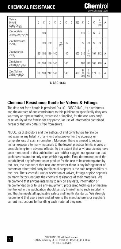
NIBCO INC. World Headquarters 1516 Middlebury St. • Elkhart, IN 46516-4740 • USA
Ph: 1.800.343.5455
www.chemtrol.com
76
The data set forth herein is provided “as is”. NIBCO INC., its distributors and the authors of and contributors to this publication specifically deny any warranty or representation, expressed or implied, for the accuracy and/or reliability of the fitness for any particular use of information contained herein or that any data is free from errors.
NIBCO, its distributors and the authors of and contributors hereto do not assume any liability of any kind whatsoever for the accuracy or completeness of such information. Moreover, there is a need to reduce human exposure to many materials to the lowest practical limits in view of possible long-term adverse effects. To the extent that any hazards may have been mentioned in this publication, we neither suggest nor guarantee that such hazards are the only ones which may exist. Final determination of the suitability of any information or product for the use to be contemplated by the user, the manner of that use, and whether there is any infringement of patents or other third-party intellectual property is the sole responsibility of the user. The successful use or operation of valves, fittings or pipe depends on many factors, not just the chemical resistance of their materials. We recommend that anyone intending to rely on any data, information or recommendation or to use any equipment, processing technique or material mentioned in this publication should satisfy himself as to such suitability and that he meets all applicable safety and health standards. We strongly recommend that users seek and adhere to the manufacturer’s or supplier’s current instructions for handling each material they use.
chEMical REsistancE
chemical Resistance guide for Valves & Fittings
Xylene (Xylol) C6H4(CH3)2
C C C C C C C 350 C C CB to
200A
Zinc Acetate Zn(CH3COO)2•2H2O
180 140 C C C
Zinc Carbonate ZnCO3 180 140
B to
212140 70 70 70 70
Zinc Chloride ZnCI2 120 180 180 140 140 400 210
B to
200194 212 A
Zinc Nitrate Zn(NO3)2•6H2O 160 180 180 140 140 180 140 100 190 A
Zinc Sulfate ZnSO4•7H2O 160 180 212 140 140 400
B to
300
B to
220171 B A
c-cRg-0613

www.chemtrol.com
NIBCO INC. World Headquarters 1516 Middlebury St. • Elkhart, IN 46516-4740 • USA
Ph: 1.800.343.545577
Nom
inal
Pi
pe S
izeAp
prox
imat
e W
eigh
t per
100
ft.
Nom
. Out
side
Di
amet
erN
om. I
nsid
e Di
amet
erW
all
Thic
knes
s (In
.) Cr
oss-
sec-
tiona
l Are
a.In
tern
al
Area
.Fl
uid
Capa
city
.Ou
tsid
e
Surfa
ce A
rea
Thre
shol
d Fl
owPV
CCP
VCPo
lypr
opyl
ene
PVDF
(In.)
(In.)
Nom
.M
in(in
.2 )(in
.2 )(ft
.2 /10
ft.)
(ft.2 /
100f
t.)(G
PM)
1/4
10.1
11.9
——
.5
40.2
82.1
29.1
19.1
67.0
62.3
214
.14
.97
1/2
20.5
24.3
14.0
24.4
.840
.526
.157
.147
.337
.217
1.13
21.9
93.
393/
427
.832
.918
.933
.01.
050
.722
.164
.154
.457
.409
2.13
27.4
96.
381
40.4
48.5
27.1
48.7
1.31
5.9
36.1
895
.179
.670
.688
3.57
34.4
310
.72
1 1/
456
.766
.937
.9—
1.66
01.
255
.202
5.1
91.9
271.
237
6.43
43.4
619
.28
1 1/
268
.981
.144
.881
.41.
900
1.47
6.2
12.2
001.
124
1.71
18.
8949
.74
26.6
72
94.9
108.
562
.311
2.6
2.37
51.
913
.231
.218
1.55
62.
874
14.9
362
.18
44.7
92
1/2
144.
916
5.4
——
2.87
52.
290
.292
5.2
762.
373
4.11
921
.40
75.2
764
.19
319
3.8
221.
312
6.6
256.
43.
500
2.86
4.3
18.3
003.
179
6.44
233
.47
91.6
310
0.40
428
3.3
323.
418
5.2
357.
04.
500
3.78
6.3
57.3
374.
647
11.2
5858
.48
117.
8117
5.44
654
1.1
616.
835
9.9
714.
36.
625
5.70
9.4
58.4
328.
873
25.5
9813
2.98
173.
4439
8.93
882
1.9
905.
8—
—8.
625
7.56
5.5
30.5
0013
.479
44.9
4823
3.49
225.
8070
0.48
1012
27.7
——
—10
.750
9.49
3.6
285
.593
19.9
8570
.778
367.
6828
1.43
1103
.02
1217
10.4
——
—12
.750
11.2
94.7
26.6
8727
.495
100.
181
520.
7933
3.79
1562
.36
1 Di
men
sion
s sh
own
are
liste
d in
AST
M D
1785
and
F44
1 fo
r PVC
and
CPV
C Sc
hedu
le 8
0 pl
astic
pip
e, re
spec
tivel
y.2
Uppe
r thr
esho
ld ra
te o
f flo
w =
5 ft
./sec
. flu
id v
eloc
ity.
pipe
, 20
ft. l
engt
hs1
diMEnsions
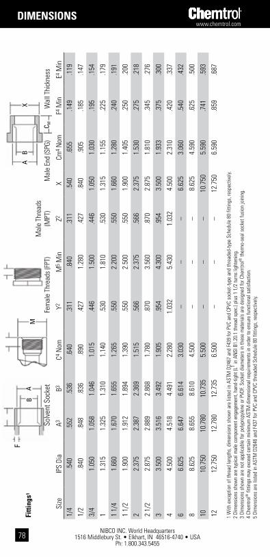
NIBCO INC. World Headquarters 1516 Middlebury St. • Elkhart, IN 46516-4740 • USA
Ph: 1.800.343.5455
www.chemtrol.com
78
1 W
ith e
xcep
tion
of th
read
leng
ths,
dim
ensi
ons
show
n ar
e lis
ted
in A
STM
D24
67 a
nd F
439
for P
VC a
nd C
PVC
sock
et-ty
pe a
nd th
read
ed-ty
pe S
ched
ule
80 fi
tting
s, re
spec
tivel
y.2
Dim
ensi
ons
show
n ar
e ty
pica
l mal
e co
mpo
nent
eng
agem
ent,
hand
-tigh
t (L1 in
AN
SI B
1.20
.1 th
read
spe
c.) p
lus
1 1/
2 tu
rns
light
enin
g.3
Dim
ensi
ons
show
n ar
e no
t app
licab
le fo
r pol
ypro
pyle
ne o
r PVD
F. So
cket
dia
met
ers
in th
ese
mat
eria
ls a
re d
esig
ned
for C
hem
trol®
ther
mo-
seal
soc
ket f
usio
n jo
inin
g.4
Chem
trol®
fitti
ngs
may
exc
eed
certa
in m
inim
um A
STM
dim
ensi
onal
requ
irem
ents
in o
rder
to e
nsur
e fu
nctio
nal s
atis
fact
ion.
5 Di
men
sion
s ar
e lis
ted
in A
STM
D26
46 a
nd F
437
for P
VC a
nd C
PVC
thre
aded
Sch
edul
e 80
fitti
ngs,
resp
ectiv
ely.
AX
B
C M
AB
F
Solv
ent S
ocke
tFe
mal
e Th
read
s (F
PT)
Mal
e Th
read
s (M
PT)
Mal
e En
d (S
PG)
Wal
l Thi
ckne
ss
Size
IPS
Dia
A3B3
C4 N
omY2
M5 M
inZ2
xCm
4 Nom
F4 M
inE4
Min
1/4
.540
.552
.536
.640
.311
.840
.311
.540
.655
.149
.119
1/2
.840
.848
.836
.890
.427
1.28
0.4
27.8
40.9
05.1
85.1
47
3/4
1.05
01.
058
1.04
61.
015
.446
1.50
0.4
461.
050
1.03
0.1
95.1
54
11.
315
1.32
51.
310
1.14
0.5
301.
810
.530
1.31
51.
155
.225
.179
1 1/
41.
660
1.67
01.
655
1.26
5.5
502.
200
.550
1.66
01.
280
.240
.191
1 1/
21.
900
1.91
21.
894
1.39
0.5
502.
500
.550
1.90
01.
405
.250
.200
22.
375
2.38
72.
369
1.51
5.5
662.
375
.566
2.37
51.
530
.275
.218
2 1/
22.
875
2.88
92.
868
1.78
0.8
703.
560
.870
2.87
51.
810
.345
.276
33.
500
3.51
63.
492
1.90
5.9
544.
300
.954
3.50
01.
933
.375
.300
44.
500
4.51
84.
491
2.28
01.
032
5.43
01.
032
4.50
02.
310
.420
.337
66.
625
6.64
76.
614
3.03
0–
–
–
6.62
53.
060
.540
.432
88.
625
8.65
58.
610
4.50
0–
––
8.62
54.
590
.625
.500
1010
.750
10.7
8010
.735
5.50
0–
–
–
10.7
505.
590
.741
.593
1212
.750
12.7
8012
.735
6.50
0–
––
12.7
506.
590
.859
.687
MFi
tting
s1diMEnsions
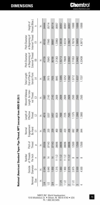
www.chemtrol.com
NIBCO INC. World Headquarters 1516 Middlebury St. • Elkhart, IN 46516-4740 • USA
Ph: 1.800.343.545579
1 W
ith e
xcep
tion
of th
read
leng
ths,
dim
ensi
ons
show
n ar
e lis
ted
in A
STM
D24
67 a
nd F
439
for P
VC a
nd C
PVC
sock
et-ty
pe a
nd th
read
ed-ty
pe S
ched
ule
80 fi
tting
s, re
spec
tivel
y.2
Dim
ensi
ons
show
n ar
e ty
pica
l mal
e co
mpo
nent
eng
agem
ent,
hand
-tigh
t (L1 in
AN
SI B
1.20
.1 th
read
spe
c.) p
lus
1 1/
2 tu
rns
light
enin
g.3
Dim
ensi
ons
show
n ar
e no
t app
licab
le fo
r pol
ypro
pyle
ne o
r PVD
F. So
cket
dia
met
ers
in th
ese
mat
eria
ls a
re d
esig
ned
for C
hem
trol®
ther
mo-
seal
soc
ket f
usio
n jo
inin
g.4
Chem
trol®
fitti
ngs
may
exc
eed
certa
in m
inim
um A
STM
dim
ensi
onal
requ
irem
ents
in o
rder
to e
nsur
e fu
nctio
nal s
atis
fact
ion.
5 Di
men
sion
s ar
e lis
ted
in A
STM
D26
46 a
nd F
437
for P
VC a
nd C
PVC
thre
aded
Sch
edul
e 80
fitti
ngs,
resp
ectiv
ely.
diMEnsions
Nom
inal
Si
ze
Outs
ide
Diam
eter
D
Num
ber
of T
hrea
ds
Per I
nch
n
Pitc
h of
Th
read
p
Nor
mal
En
gage
men
t By
Han
d
L1
Leng
th o
f Ef
fect
ive
Thre
ad
L2
Wre
nch
Mak
eup
Leng
th f
or In
ter-
nal T
hrea
d L3
Tota
l Len
gth:
En
d of
Pip
e to
Va
nish
Poi
nt
L4
Pitc
h Di
amet
er
at B
egin
ning
of
Exte
rnal
Thr
ead
E0
Pitc
h Di
amet
er
at B
egin
ning
of
Inte
rnal
Thr
ead
E1
Heig
ht o
f Th
read
(Max
.) h
in.
in.
in.
in.
in.
in.
in.
in.
in.
in.
1/4
0.54
018
.055
56.2
28.4
018
.166
7.5
946
.477
39.4
9163
.044
44
1/2
0.84
014
.071
43.3
20.5
337
.214
3.7
815
.758
43.7
7843
.057
14
3/4
1.05
014
.071
43.3
39.5
457
.214
3.7
935
.967
68.9
8887
.057
14
11.
315
11 1
/2.0
8696
.400
.682
8.2
609
.984
51.
2136
31.
2386
3.0
6957
1 1/
41.
660
11 1
/2.0
8696
.420
.706
8.2
609
1.00
851.
5571
31.
5833
8.0
6957
1 1/
21.
900
11 1
/2.0
8696
.420
.723
5.2
609
1.02
521.
7960
91.
8223
4.0
6957
22.
375
11 1
/2.0
8696
.436
.756
5.2
609
1.05
822.
2690
22.
2962
7.0
6957
2 1/
22.
875
8.1
2500
.682
1.13
75.2
500
1.57
122.
7195
32.
7621
6.1
0000
33.
500
8.1
2500
.766
1.20
00.2
500
1.63
373.
3406
23.
3885
0.1
0000
44.
500
8.1
2500
.844
1.30
00.2
500
1.73
374.
3343
84.
3871
2.1
0000
nat
iona
l (a
mer
ican
) sta
ndar
d ta
per p
ipe
thre
ad, n
pt (e
xcer
pt fr
om a
nsi
b1.
20.1
)
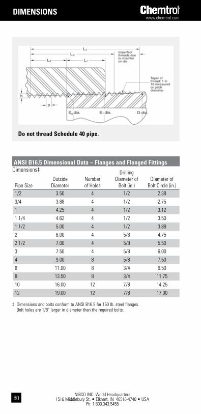
NIBCO INC. World Headquarters 1516 Middlebury St. • Elkhart, IN 46516-4740 • USA
Ph: 1.800.343.5455
www.chemtrol.com
80
diMEnsions
do not thread schedule 40 pipe.
Dimensions‡
‡ Dimensions and bolts conform to ANSI B16.5 for 150 lb. steel flanges. Bolt holes are 1/8" larger in diameter than the required bolts.
ansi b16.5 dimensional data – Flanges and Flanged Fittings
Pipe SizeOutside
DiameterNumberof Holes
Drilling Diameter of
Bolt (in.)Diameter of
Bolt Circle (in.)1/2 3.50 4 1/2 2.38
3/4 3.88 4 1/2 2.75
1 4.25 4 1/2 3.12
1 1/4 4.62 4 1/2 3.50
1 1/2 5.00 4 1/2 3.88
2 6.00 4 5/8 4.75
2 1/2 7.00 4 5/8 5.50
3 7.50 4 5/8 6.00
4 9.00 8 5/8 7.50
6 11.00 8 3/4 9.50
8 13.50 8 3/4 11.75
10 16.00 12 7/8 14.25
12 19.00 12 7/8 17.00

www.chemtrol.com
NIBCO INC. World Headquarters 1516 Middlebury St. • Elkhart, IN 46516-4740 • USA
Ph: 1.800.343.545581
notEs

NIBCO INC. World Headquarters 1516 Middlebury St. • Elkhart, IN 46516-4740 • USA
Ph: 1.800.343.5455
www.chemtrol.com
82
ValVEs
key to chemtrol Valve Figure number system
x xx xx - x - xx - siZE 1 2 3 4 5 6
1 End configurations S SocketF FlangedT Threaded (female)M Threaded (male) A Hose x Male ThreadedW Wafer Style ButterflyU Universal (socket and threaded)
2 body Material 45 PVC Schedule 8051 CPVC Schedule 8061 Black Polypropylene (PP)62 Chem-Pure® Natural Polypropylene (PP)65 Red ® PVDF66 Natural Kynar® PVDF
3 types of Valves AC AngleBC Ball CheckBF Butterfly (Model B)BG Butterfly (Model C)CC Chemcock® CN NeedleD2 Diverter (3-Way, 2-Position)FV Ball FootM3 Multiport (3-Way, 3 Position)TB Tru-Bloc® True Union Ball ValveYP Y-Pattern
4 o-Ring Material
E EPDMV FKM
5 operating Mechanisms
NO NoneLH Lever Handle, ManualRH Round Safety Handle, ManualGO Gear Operator, Manual
6 size
State Valve Size Kynar® is a registered trademark of Arkema Inc.

www.chemtrol.com
NIBCO INC. World Headquarters 1516 Middlebury St. • Elkhart, IN 46516-4740 • USA
Ph: 1.800.343.545583
ValVEs
PVC and CPVC Tru-Bloc® True Union Ball Valve, Model D
1 Handle is not symmetrical about centerline. Dimensions shown represent the longest opera-tional radius. The handle position is correctly shown for the 1/2" - 3" True Union valve style.
2 Weight for 1/2" - 2" TU figures includes both sets of end connectors.3 CV values computed for basic valve laying lengths (G).
Valve Size
TU Figures End-to-End
ESoc.
FThd.
GSoc.
HThd.
JFlgd.
PVC Approx.2Wt. Lbs.
CPVC Approx.2Wt. Lbs.
1/2 4.20 4.10 2.42 2.44 6.30 0.350 0.3703/4 5.02 4.62 3.02 3.05 7.34 0.690 0.7301 5.47 5.32 3.22 3.40 8.17 0.960 1.000
1 1/4 6.53 6.07 4.01 4.06 9.41 2.155 2.2551 1/2 6.89 6.23 4.10 4.18 10.05 2.190 2.315
2 8.04 7.39 5.01 5.19 11.44 4.410 4.670
dimensions–weights–Flow coefficients
Valve Size
TU Figures ProfileFluid Flow Coefficient
A1 B C DK
Flgd.CV3
TU1/2 2.07 2.16 1.82 .50 3.50 6.43/4 2.74 2.90 2.36 .75 3.88 38.71 2.74 3.07 2.73 1.00 4.26 58.2
1 1/4 2.62 3.91 4.07 1.25 4.62 61.71 1/2 2.62 3.91 4.07 1.50 5.00 117.4
2 3.12 4.71 5.23 2.00 6.00 178.4
* As original equipment, 1/2" - 2" True Union Tru-Bloc valve models are supplied with universal connectors (i.e., a set of both socket and thread end connectors).
Valve Style
Elasto-meric Trim
PVC CPVC
Soc. Thd. Flgd. Soc. Thd. Flgd.
TU/TB FKM U45TB-V* U45TB-V* F45TB-V U51TB-V* U51TB-V* F51TB-V
EPDM U45TB-E* U45TB-E* F45TB-E U51TB-E* U51TB-E* F51TB-E
chemtrol Figure number

NIBCO INC. World Headquarters 1516 Middlebury St. • Elkhart, IN 46516-4740 • USA
Ph: 1.800.343.5455
www.chemtrol.com
84
ValVEs
PVC and CPVC Tru-Bloc® True Union Ball Valve, Model C
Valve Style
Elasto-meric Trim
PVC CPVC
Soc. Thd.* Flgd. Soc. Thd.* Flgd.
TU/TB FKM S45TB-V T45TB-V F45TB-V S51TB-V T51TB-V F51TB-V
EPDM S45TB-E T45TB-E F45TB-E S51TB-E T51TB-E F51TB-E
chemtrol Figure number
* Thread end connections are not available for 6" valves.
1 Handle is not symmetrical about center line. Dimensions shown represent the longest opera-tional radius. The handle position is correctly shown for the 3" True Union valve style, but the position must be rotated 180° from that shown for the 4" - 6" True Unions.
2 Weight includes socket end connections only for 3" - 6" sizes. The material represented is PVC in all cases.
3 CV values computed for basic valve laying lengths (G).4 The 6" ball valve is a Venturi design derived from the 4" valve: a 4" end connector and a 6" coupling are connected by a 6" x 4" Venturied reducer, with a union nut captured within the assembly. Threaded end connection not available.
Valve Size
TU Figures End-to-End
EThd.
FSoc.
GSoc.
HFlgd
Approx.2Wt. Lbs.
3 10.39 10.39 6.58 14.63 11.254 12.22 12.22 7.66 17.63 17.6864 NA 30.22 24.16 24.08 29.25
Valve Size
TU Figures ProfileFluid Flow Coefficient
A1 B C D N PCV3
TU3 4.00 5.59 7.18 3.00 7.42 7.50 13484 8.00 6.05 8.78 4.00 8.52 9.00 260264 8.00 6.05 8.78 4.00 11.90 11.05 2602
dimensions–weights–Flow coefficients

www.chemtrol.com
NIBCO INC. World Headquarters 1516 Middlebury St. • Elkhart, IN 46516-4740 • USA
Ph: 1.800.343.545585
* Thread end connections are not available for 6" valves.
ValVEs
PVC and CPVC Tru-Bloc® True Union Vented (Bleach) Ball Valve, Model D
the problem Sodium hypochlorite, used in water treatment, aquatic centers, and paper and textile applications, can become trapped in the body cavity of a closed ball valve and create conditions that may result in damage to the valve or system as a result of unstable chemical decomposition.
the chemtrol solution The Vented Ball Valve is a special factory modification to a PVC or CPVC True Union Ball Valve that effectively vents sodium hypochlorite out-gassing to the pressure port. In addition, the inner valve surfaces are kept constantly wetted to ensure problem-free use of the ball valves in bleach transfer and injection applications.
background In the search for a safer alternative to chlorine vacuum gas injection, fresh and wastewa-ter treatment, paper and textile plants, and aquatic centers are converting to the use of sodium hypochlorite as a disinfectant or bleaching agent. A high pH level characterizes commercial bleach, which consists of a nominal 15% solution of sodium hypochlorite along with approximately 1-2% of sodium hydroxide to act as a chemical stabilizer. Known as a good oxidizer, the solution has been found to cause stress cracking in polyethylene and polypropylene materials. And metallic materials react, causing rapid decomposition of the “hypo.” However, PVC and CPVC, with fluorocarbon rubber (FKM) seals, have been suc-cessfully used for years to handle this aggressive chemical solution.
Some system design considerations are important, though. Heat, time, and positive ions are enemies of bleach stability. When a ball valve is closed in periods of inactivi-ty, the bleach will decompose over time liberating oxygen gas. The decomposition rate is increased by heat absorbed from sun shining on exposed piping, or by reaction heat resulting from debris trapped in a ball valve body between the ball and its seats. Gas pressure may slowly build in the closed valve cavity, or quite rapidly in the reac-tive case. Such conditions may result in damage to the valve or system.
Also, evaporation of sodium hypochlorite in the ball cavity can lead to the formation of crystalline residue that eventually embeds in the PTFE seats of a ball valve and sig-nificantly raises the turning torque due to excessive wear on the ball by fouled seats. Such conditions may result in a broken valve stem, frozen valve ball, or other damage to the valve or system.
The Chemtrol® Vented Ball Valve offers a viable solution for sodium hypochlorite transfer and injection applications. Our unique factory-assembled bleach ball valve has effectively eliminated the problems associated with these uses. By ensuring that all inner surfaces of the valve are kept constantly wetted and vented to the upstream side when the valve is in the closed position, we have eliminated the conditions required for gas accumulation and caustic crystallization in the body cavity.
Permanent BleachAnd Vent/FlowDirectional Marking
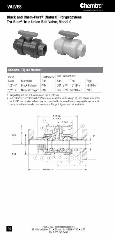
NIBCO INC. World Headquarters 1516 Middlebury St. • Elkhart, IN 46516-4740 • USA
Ph: 1.800.343.5455
www.chemtrol.com
86
ValVEs
Black and Chem-Pure® (Natural) PolypropyleneTru-Bloc® True Union Ball Valve, Model C
Valve Sizes Materials
Elastomeric Trim
End Connections
Soc.. Thd. Flgd.
1/2"- 4" Black Polypro FKM S61TB-V1 T61TB-V1 F61TB-V1
1/2" - 4" Natural Polypro FKM S62TB-V2 S62TB-V2 NA2
chemtrol Figure number
1 Flanged figures are not available in the 1 1/4" size.2 Socket Chem-Pure® (natural PP) Valves are available in the range of sizes shown except for
the 1 1/4" size. Socket valves may be converted to threaded by exchanging the socket end connector with a threaded end connector. Flanged figures are not available.
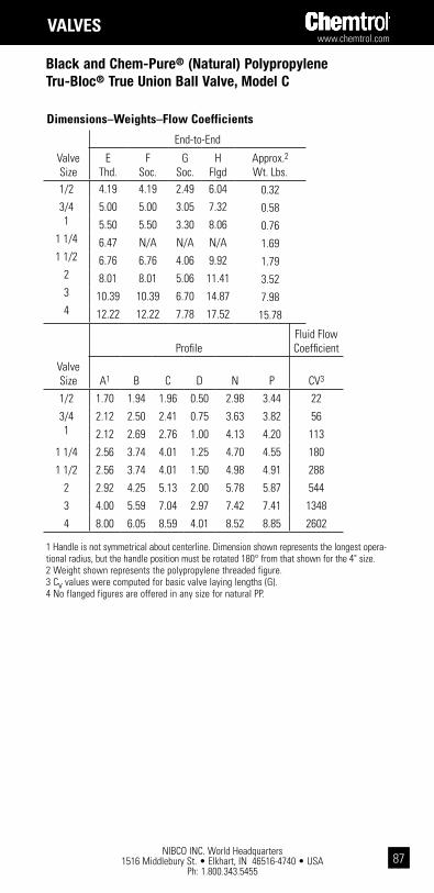
www.chemtrol.com
NIBCO INC. World Headquarters 1516 Middlebury St. • Elkhart, IN 46516-4740 • USA
Ph: 1.800.343.545587
ValVEs
1 Handle is not symmetrical about centerline. Dimension shown represents the longest opera-tional radius, but the handle position must be rotated 180° from that shown for the 4" size.2 Weight shown represents the polypropylene threaded figure.3 Cv values were computed for basic valve laying lengths (G).4 No flanged figures are offered in any size for natural PP.
dimensions–weights–Flow coefficients
Valve Size
End-to-End
EThd.
FSoc.
GSoc.
HFlgd
Approx.2Wt. Lbs.
1/2 4.19 4.19 2.49 6.04 0.323/4 5.00 5.00 3.05 7.32 0.581 5.50 5.50 3.30 8.06 0.76
1 1/4 6.47 N/A N/A N/A 1.691 1/2 6.76 6.76 4.06 9.92 1.79
2 8.01 8.01 5.06 11.41 3.523 10.39 10.39 6.70 14.87 7.984 12.22 12.22 7.78 17.52 15.78
Valve Size
ProfileFluid Flow Coefficient
A1 B C D N P CV3
1/2 1.70 1.94 1.96 0.50 2.98 3.44 22
3/4 2.12 2.50 2.41 0.75 3.63 3.82 561 2.12 2.69 2.76 1.00 4.13 4.20 113
1 1/4 2.56 3.74 4.01 1.25 4.70 4.55 180
1 1/2 2.56 3.74 4.01 1.50 4.98 4.91 288
2 2.92 4.25 5.13 2.00 5.78 5.87 544
3 4.00 5.59 7.04 2.97 7.42 7.41 1348
4 8.00 6.05 8.59 4.01 8.52 8.85 2602
Black and Chem-Pure® (Natural) PolypropyleneTru-Bloc® True Union Ball Valve, Model C
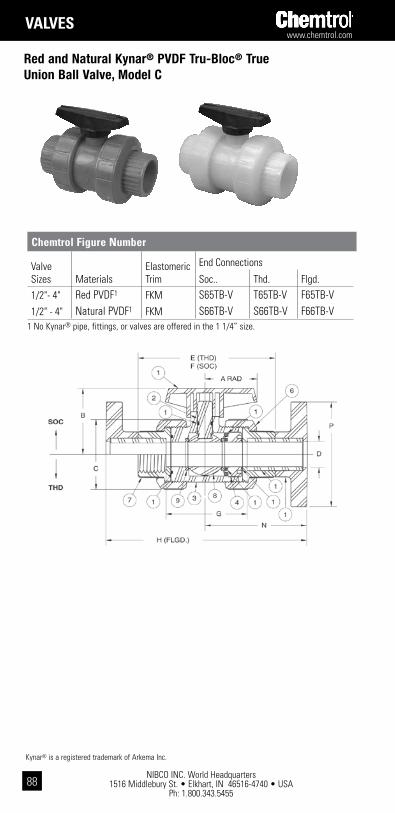
NIBCO INC. World Headquarters 1516 Middlebury St. • Elkhart, IN 46516-4740 • USA
Ph: 1.800.343.5455
www.chemtrol.com
88
1 No Kynar® pipe, fittings, or valves are offered in the 1 1/4” size.
Red and Natural Kynar® PVDF Tru-Bloc® TrueUnion Ball Valve, Model C
Valve Sizes Materials
Elastomeric Trim
End Connections
Soc.. Thd. Flgd.
1/2"- 4" Red PVDF1 FKM S65TB-V T65TB-V F65TB-V1/2" - 4" Natural PVDF1 FKM S66TB-V S66TB-V F66TB-V
chemtrol Figure number
Kynar® is a registered trademark of Arkema Inc.
ValVEs
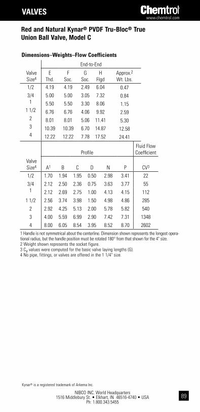
www.chemtrol.com
NIBCO INC. World Headquarters 1516 Middlebury St. • Elkhart, IN 46516-4740 • USA
Ph: 1.800.343.545589
Red and Natural Kynar® PVDF Tru-Bloc® TrueUnion Ball Valve, Model C
dimensions–weights–Flow coefficients
Valve Size4
End-to-End
EThd.
FSoc.
GSoc.
HFlgd
Approx.2Wt. Lbs.
1/2 4.19 4.19 2.49 6.04 0.473/4 5.00 5.00 3.05 7.32 0.841 5.50 5.50 3.30 8.06 1.15
1 1/2 6.76 6.76 4.06 9.92 2.592 8.01 8.01 5.06 11.41 5.303 10.39 10.39 6.70 14.87 12.584 12.22 12.22 7.78 17.52 24.41
Valve Size4
ProfileFluid Flow Coefficient
A1 B C D N P CV3
1/2 1.70 1.94 1.95 0.50 2.98 3.41 22
3/4 2.12 2.50 2.36 0.75 3.63 3.77 551 2.12 2.69 2.75 1.00 4.13 4.15 112
1 1/2 2.56 3.74 3.98 1.50 4.98 4.86 285
2 2.92 4.25 5.13 2.00 5.78 5.82 540
3 4.00 5.59 6.99 2.90 7.42 7.31 1348
4 8.00 6.05 8.54 3.95 8.52 8.70 2602
Kynar® is a registered trademark of Arkema Inc.
1 Handle is not symmetrical about the centerline. Dimension shown represents the longest opera-tional radius, but the handle position must be rotated 180° from that shown for the 4" size.2 Weight shown represents the socket figure.3 Cv values were computed for the basic valve laying lengths (G).4 No pipe, fittings, or valves are offered in the 1 1/4" size.
ValVEs

NIBCO INC. World Headquarters 1516 Middlebury St. • Elkhart, IN 46516-4740 • USA
Ph: 1.800.343.5455
www.chemtrol.com
90
ValVEs
PVC and CPVC 3-Way, 3-Position (Multiport/Diverter) True Union Ball Valve, Model A
Diverter
Multiport

www.chemtrol.com
NIBCO INC. World Headquarters 1516 Middlebury St. • Elkhart, IN 46516-4740 • USA
Ph: 1.800.343.545591
ValVEs
PVC and CPVC 3-Way, 3-Position (Multiport /Diverter) True Union Ball Valve, Model A
chemtrol Figure numbers
Elastomeric PVC CPVC Valve Style Trim Soc. Thd. Soc. Thd. 1/2” – 2” Multiport FKM S45M3-V T45M3-V S51M3-V T51M3-V(3-Way/3-Position) EPDM S45M3-E T45M3-E S51M3-E T51M3-E
1 Handle is not symmetrical about stem centerline. Dimension shown represents the longest operational radius.
2 Weights shown for socket figures are CPVC models. Weights for threaded figures are PVC models.
3 Cv values were computed using equivalent cylinder length for 90° turn with full bore.
* 1 1/2" valve has conventional port on center outlet.
dimensions–weights–Flow coefficients
Valve Size
Soc. & Thd. Figures
A1 B C D
1/2 2.07 1.94 2.00 0.50
3/4 2.74 2.50 2.44 0.75
1 2.74 2.69 2.86 1.00
1 1/4 2.62 3.74 4.08 1.25
1 1/2 2.62 3.74 4.08 1.25
2 3.12 4.25 5.25 2.00
Valve Size
Socket Figures
F G J K RApprox.2Wt. Lbs.
1/2 4.19 2.41 3.56 2.69 2.13 0.64
3/4 5.00 2.97 4.19 3.19 2.50 1.15
1 5.50 3.22 4.63 3.50 2.75 1.59
1 1/4 6.47 3.94 5.88 4.63 3.25 3.43
1 1/2 6.76 3.98 6.00 4.63 3.38 3.62
2 8.01 4.98 7.08 5.63 3.96 7.02
Valve Size
Threaded FiguresFluid Flow Coefficient
E H PApprox.2Wt. Lbs. CV3
1/2 4.00 3.50 2.06 0.60 8
3/4 4.63 4.00 2.31 1.05 19
1 5.18 4.44 2.63 1.50 36
1 1/4 6.10 5.63 3.06 3.24 55
1 1/2 6.15 5.63 3.06 3.37 55
2 7.35 6.81 3.62 6.25 149

NIBCO INC. World Headquarters 1516 Middlebury St. • Elkhart, IN 46516-4740 • USA
Ph: 1.800.343.5455
www.chemtrol.com
92
ValVEs
PVC Compact Economy Ball Valve
chemtrol Figure numbersMaterial O-Rings Ends (1/2" - 2")
PVC EPDM Soc. S45CE-EPVC EPDM Thd. T45CE-EPVC FKM Soc. S45CE-VPVC FKM Thd. T45CE-E
Size Thd./In.(NPT)In. mm d1 d2 d3 D L L1
1/2 15 14 0.84 0.85 0.55 1.18 3.27 2.76
3/4 20 14 1.05 1.06 0.79 1.50 3.74 3.46
1 25 11.5 1.31 1.32 0.98 1.77 4.17 3.94
1 1/4 32 11.5 1.65 1.67 1.18 2.13 4.48 3.94
1 1/2 40 11.5 1.89 1.91 1.42 2.44 5.12 4.29
2 50 11.5 2.39 2.39 1.83 3.03 5.79 5.28
Size
In. mm I H1 H2 W Weight/lbs. Cv1/2 15 0.87 2.44 1.69 1.50 0.18 8.84
3/4 20 1.00 3.07 2.13 1.93 0.18 —
1 25 1.12 3.66 2.56 2.24 0.49 25.24
1 1/4 32 1.25 3.86 2.64 2.48 0.64 38.53
1 1/2 40 1.38 4.53 3.07 2.95 0.94 51.28
2 50 1.50 5.31 3.50 3.62 1.50 96.67
dimensions–weights–Flow coefficients

www.chemtrol.com
NIBCO INC. World Headquarters 1516 Middlebury St. • Elkhart, IN 46516-4740 • USA
Ph: 1.800.343.545593
ValVEs
PVC Butterfly Valves, Model C
Disk Operating Material Mechanism 2" – 10" Figure No.1
EPDM Lever Handle2 W45BG-E-3 Gear Operator W45BG-E-51 10" is available with gear operator only.2 Includes throttle plate and lock.
chemtrol Figure number
cv table Degrees Open Size 10° 20° 30° 40° 50° 60° 70° 80° 90° 2 2.5 8 18 33 50 73 100 131 166 2 1/2 3.7 12 27 49 74 109 148 195 247 3 4.3 16 35 62 94 135 180 235 290 4 8.6 34 76 137 215 310 420 550 690 6 17.5 67 200 265 410 580 790 1040 1340 8 20.8 83 190 320 530 770 1060 1380 1780 10 50.0 195 430 775 1200 1775 2700 3100 4000
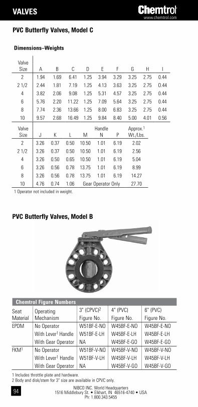
NIBCO INC. World Headquarters 1516 Middlebury St. • Elkhart, IN 46516-4740 • USA
Ph: 1.800.343.5455
www.chemtrol.com
94
ValVEs
1 Operator not included in weight.
PVC Butterfly Valves, Model C
dimensions–weights
Valve Size A B C D E F G H I
2 1.94 1.69 6.41 1.25 3.94 3.29 3.25 2.75 0.44
2 1/2 2.44 1.81 7.19 1.25 4.13 3.63 3.25 2.75 O.44
4 3.82 2.06 9.08 1.25 5.31 4.57 3.25 2.75 0.44
6 5.76 2.20 11.22 1.25 7.09 5.64 3.25 2.75 0.44
8 7.74 2.36 13.66 1.25 8.00 6.83 3.25 2.75 0.44
10 9.57 2.68 16.49 1.25 9.84 8.40 5.00 4.01 0.56
Valve Size
Handle N
Approx.1 Wt./Lbs.J K L M P
2 3.26 0.37 0.50 10.50 1.01 6.19 2.02
2 1/2 3.26 0.37 0.50 10.50 1.01 6.19 2.56
4 3.26 0.50 0.65 10.50 1.01 6.19 5.04
6 3.26 0.56 0.78 13.75 1.01 6.19 8.99
8 3.26 0.56 0.78 13.75 1.01 6.19 14.27
10 4.76 0.74 1.06 Gear Operator Only 27.70
chemtrol Figure numbers
Seat Operating 3" (CPVC)2 4" (PVC) 6" (PVC)Material Mechanism Figure No. Figure No. Figure No.EPDM No Operator W51BF-E-NO W45BF-E-NO W45BF-E-NO With Lever1 Handle W51BF-E-LH W45BF-E-LH W45BF-E-LH With Gear Operator NA W45BF-E-GO W45BF-E-GOFKM1 No Operator W51BF-V-NO W45BF-V-NO W45BF-V-NO With Lever1 Handle W51BF-V-LH W45BF-V-LH W45BF-V-LH With Gear Operator NA W45BF-V-GO W45BF-V-GO
1 Includes throttle plate and hardware.2 Body and disk/stem for 3" size are available in CPVC only.
PVC Butterfly Valves, Model B

www.chemtrol.com
NIBCO INC. World Headquarters 1516 Middlebury St. • Elkhart, IN 46516-4740 • USA
Ph: 1.800.343.545595
ValVEs
NIBCOCHEMTROL
PVC Butterfly Valves, Model B
dimensions–weights
1 Operator not included in weight.
cv table Degrees Open Size 10° 20° 30° 40° 50° 60° 70° 80° 90° 3 4.3 16 35 62 94 135 180 235 290 4 8.6 34 76 137 215 310 420 550 690 6 17.5 67 200 265 410 580 790 1040 1340
Valve Size A B C D E J G
3 4.75 1.26 7.00 3.06 8.50 2.00 3.62
4 6.13 1.22 9.00 4.00 10.63 2.22 3.62
6 7.50 1.62 11.00 5.97 13.00 2.77 3.76
Valve Size
Handle P
Approx. Wt./Lbs.G H R M N
3 3.62 3.38 .37 10.50 1.01 6.19 3.25
4 3.62 3.38 .50 10.50 1.01 6.19 6.00
6 3.76 3.50 .56 13.75 1.01 6.19 12.00

NIBCO INC. World Headquarters 1516 Middlebury St. • Elkhart, IN 46516-4740 • USA
Ph: 1.800.343.5455
www.chemtrol.com
96
ValVEs
chemtrol Figure numbersType Valve End Conn Elastomeric Trim Materials PVC CPVC
Soc. FKM U45BC-V1 U51BC-V1
EPDM U45BC-E1 U51BC-E1
Thd. FKM U45BC-V1 U51BC-V1
EPDM U45BC-E1 U51BC-E1
Flgd. FKM F45BC-V F51BC-V EPDM F45BC-E F51BC-E
1 1/2"–2" PVC and CPVC TU ball check figures are supplied with universal connection components (i.e., a set of both socket and threaded end connectors). For 3" and 4" sizes of PVC and CPVC BC valves, replace U in the figure no. with S or T for socket or threaded units respectively.
Ball Check Valve
PVC and CPVC True Union Ball Check, Foot, andVent Valves

www.chemtrol.com
NIBCO INC. World Headquarters 1516 Middlebury St. • Elkhart, IN 46516-4740 • USA
Ph: 1.800.343.545597
ValVEs
1 Foot valve screen housing assemblies are available for the field conversion of PVC and CPVC TU ball check valves in sizes 1/2" - 4".
2 Weights shown for ball valve figures are PVC threaded models. For an approximation of CPVC check valve weights, the PVC weight may be multiplied by factor of 1.123. Weights shown for foot valves are actually those for PVC F.V. screen housing assemblies. So, the weight for a CPVC F.V. screen housing assy. may be found by multiplying the PVC weight by the 1.123 fac-tor. These must be added to check valve weight for full foot valve weight.
3 Cv values are based on the basic valve laying length (G).4 The 4" PVC and CPVC check valves are fabricated by solvent cementing either reducing flang-es or reducing couplings onto the ends of a 3" valve with plain-end nipples.
Ball Check/Foot Ball Check Valve
Valve Size A B C D
E Thd.
F Soc.
G Soc.
H Flgd.
Approx.2 Wt. Lbs.
1/2 3.50 1.98 2.63 0.50 3.94 4.13 2.36 6.27 0.42
3/4 3.88 2.44 2.63 0.75 4.65 5.02 3.00 7.38 0.72
1 4.26 2.83 3.63 1.00 5.08 5.40 3.12 7.99 1.05
1 1/4 4.62 4.08 5.50 1.25 6.38 6.75 4.22 9.65 2.46
1 1/2 5.00 4.08 5.50 1.50 6.38 6.99 4.21 10.18 2.62
2 6.00 5.23 5.50 2.00 7.36 8.02 4.99 11.45 4.76
3 7.50 7.17 5.50 3.00 9.98 9.98 6.17 14.22 9.21
44 9.00 7.17 5.50 3.00 20.76 20.76 16.20 16.14 14.18
PVC and CPVC True Union Ball Check, Foot, andVent Valves
Ball Foot ValveSeating Head
Ft - H20Fluid Flow Coefficient
Valve Size
J Thd.
K Soc.
M Flgd.
Approx.3 Wt. Lbs Vert. Horiz. CV
3
1/2 6.13 6.19 7.25 0.23 6 7 5
3/4 6.88 7.13 8.25 0.29 6 7 10
1 8.13 8.25 9.63 0.37 4 5 19
1 1/4 11.13 11.25 12.75 1.34 4 5 37
1 1/2 11.13 11.50 13.13 1.34 4 5 56
2 11.75 12.13 13.75 1.88 4 5 101
3 13.38 13.38 15.63 3.00 3 4 251
44 18.50 18.50 16.25 3.00 3 4 251
dimensions–weights–Flow coefficients

NIBCO INC. World Headquarters 1516 Middlebury St. • Elkhart, IN 46516-4740 • USA
Ph: 1.800.343.5455
www.chemtrol.com
98
ValVEs
chemtrol Figure numbers
Type
Valve
End
Conn
Elastomeric
Trim
Materials
Black Polypro
Chem-Pure Natural Polypro
Red PVDF
Natural PVDF
Ball
Check
Valve
Soc. FKM S61BC-V S62BC-V S65BC-V S66BC-V
Thd. FKM T61BC-V NA T65BC-V T66BC-V
Flgd. FKM F61BC-V NA F65BC-V F66BC-V
chemtrol Figure numbers
Polypropylene and Kynar® PVDF True Union BallCheck, and Vent Valves
Kynar® is a registered trademark of Arkema Inc.

www.chemtrol.com
NIBCO INC. World Headquarters 1516 Middlebury St. • Elkhart, IN 46516-4740 • USA
Ph: 1.800.343.545599
ValVEs
Polypropylene and Kynar® PVDF True Union BallCheck, and Vent Valves
1 Dimensions shown are for PVC and CPVC. Due to molding shrinkage the dimensions for PP and PVDF would be somewhat less, and the end-to-end length of threaded equals socket valves.
2 Weights shown for ball valve figures are PVC threaded models. For an approximation of PVDF, and PP check valve weights the PVC weight may be multiplied by factors of 1.275, or 0.656 respectively.
3 Cv values are based on the basic valve laying length (G).
Ball Check/Foot
Valve Size A B C D
E Thd.
1/2 3.50 1.98 2.63 0.50 3.94
3/4 3.88 2.44 2.63 0.75 4.65
1 4.26 2.83 3.63 1.00 5.08
1 1/2 5.00 4.08 5.50 1.50 6.38
2 6.00 5.23 5.50 2.00 7.36
Ball Check ValveSeating Head
Ft - H20Fluid Flow Coefficient
Valve Size
F Soc.
G Soc.
H Flgd.
Approx.2 Wt. Lbs Vert. Horiz. CV
3
1/2 4.13 2.36 6.27 0.42 6 7 5
3/4 5.02 3.00 7.38 0.72 6 7 10
1 5.40 3.12 7.99 1.05 4 5 19
1 1/2 6.99 4.21 10.18 2.62 4 5 56
2 8.02 4.99 11.45 4.76 4 5 101
dimensions1–weights–Flow coefficients
Kynar® is a registered trademark of Arkema Inc.

NIBCO INC. World Headquarters 1516 Middlebury St. • Elkhart, IN 46516-4740 • USA
Ph: 1.800.343.5455
www.chemtrol.com
100
ValVEs
chemtrol Figure no.
T45AC-V
Both styles available with threaded end connections only.
PVC Angle and Y-Pattern Globe Valves
chemtrol Figure no.
T45YC-V
Kynar® is a registered trademark of Arkema Inc.

www.chemtrol.com
NIBCO INC. World Headquarters 1516 Middlebury St. • Elkhart, IN 46516-4740 • USA
Ph: 1.800.343.5455101
ValVEs
PVC Angle and Y-Pattern Globe Valves
1 Available with threaded end connections only.2 CV measured with valves completely open.
Common Dimensions
Valve Size
Hub Dia. E
Close Stroke F
Handle Dia. H
1/4 0.88 .44 1.32
1/2 1.25 .75 2.19
3/4 1.50 .94 2.19
1 1.75 1.19 2.19
dimensions–weights–Flow coefficients
Angle Valve1
Valve Size
Center-To-Face A
Open Max. B
Flow CoefficientCv2
Approx. Weight Lbs.
1/4 0.88 3.56 1.1 0.11
1/2 1.31 5.38 5.4 0.28
3/4 1.41 6.50 9.9 0.47
1 1.88 7.88 15.8 0.69
Y-Pattern Valve1
Valve Size
End-To-EndD
Open Max. C
Flow Coefficient Cv2
Approx Weight Lbs.
1/4 2.75 2.75 3.1 0.12
1/2 3.50 4.63 17.7 0.30
3/4 4.25 5.56 32.5 0.53
1 5.00 6.31 49.3 0.73
Kynar® is a registered trademark of Arkema Inc.

NIBCO INC. World Headquarters 1516 Middlebury St. • Elkhart, IN 46516-4740 • USA
Ph: 1.800.343.5455
www.chemtrol.com
102
ValVEs
PVC Chemcock® Valves
chemtrol Figure no. A45CC-V 1/4" Hose x 1/4" MPT M45CC-V 1/4" MPT x 1/4" MPT

www.chemtrol.com
NIBCO INC. World Headquarters 1516 Middlebury St. • Elkhart, IN 46516-4740 • USA
Ph: 1.800.343.5455103
ValVEs
Calibrated Needle Lab Valves
Knob Position GPM @ Constant 50 PSI 8 .85 7 1.41 6 1.79 5 2.15 4 2.42 3 3.15 2 4.40 1 4.50
chemtrol Figure no. T45CN-V 1/4" FPT x 1/4" FPT

NIBCO INC. World Headquarters 1516 Middlebury St. • Elkhart, IN 46516-4740 • USA
Ph: 1.800.343.5455
www.chemtrol.com
104
ValVEs
Alternative Manual Operators
Use Valve Size 1 1/4& 11/2 Accessory 1/2 3/4 & 1 2
2" Sq. Nut Stem Adapter
PVC for TB Ball Valves 21630007 21630009 21630011 21630012
PVC for HV Ball Valves 21630007 21630009 21630011 21630011
Round Safety Handle
PVC for TB Ball Valves 81616007 81616009 81621011 81621012
PVC for HV Ball Valves 81616007 81616009 81621011 81621011
part numbers for alternative Manual operators
Use
Accessory 2 1/2 3 4 6 8
2" Sq. Nut Stem Adapter
PVC for TB Ball Valves — 21630014 21630016 21630016 —
PVC for HV Ball Valves — — — — —
Round Safety Handle
PVC for TB Ball Valves — — — — —
PVC for HV Ball Valves — — — — —
pVc standoff stem Extensions For ball Valve
Length Valve SizeOf Ext. 1/2 3/4 & 1 1 1/4 2 3 4 & 6 & 1 1/2 1" Long 21618007 21618009 — — — —2" Long 21617150 21617175 21617214 21617226 21617069 216170763" Long 21617151 21617177 21617216 21617229 21617249 216170784" Long 21617153 21617179 21617218 21617231 21617251 216172575" Long 21617155 21617181 21617220 21617228 21617299 216172986" Long 21617157 21617183 21617222 21617235 21617252 21617260

www.chemtrol.com
NIBCO INC. World Headquarters 1516 Middlebury St. • Elkhart, IN 46516-4740 • USA
Ph: 1.800.343.5455105
ValVEs
Alternative Manual Operators
Round safety handle–Design prevents accidental operation of low-torque ball valve by snagging the lever handle with personal clothing or equipment. Suitable for PVC and CPVC Tru-Bloc® True Union Ball Valves, Model D.
2" square nut stem adapter–Permits operation of a valve with a standard utility (AWWA) wrench. The most common application is for valves located in an underground valve box. The square nut for ball valves is made from PVC. It snaps onto the stem and locks into the slot for turning-stops of a ball valve of any material, in place of its standard handle.
standoff stem Extensions for ball Valves–Provide handle clearance, with the integrity of turning-stops, for insulating, panel-mounting, or shallow submerged applications. These extensions are made of solid PVC, and are short; so top support is not required. Although priced in increments of 1" standoff, between handle and stem, they can be supplied in exact lengths if specified when ordered. And, if the extension is to be installed on a valve of material other than PVC or CPVC, that must also be specified when ordering.

NIBCO INC. World Headquarters 1516 Middlebury St. • Elkhart, IN 46516-4740 • USA
Ph: 1.800.343.5455
www.chemtrol.com
106
ValVEs
Valve Lockout Devicesty
pelo
ckou
t d
evic
elo
catio
n M
ount
ed
Valv
e si
ze
1/2
3/4
11
1/4
1 1/
22
2 1/
23
4 6
8
BV H
andl
e an
d Lo
ckin
g Ri
ng K
itFi
eld
8164
4007
8164
4008
8164
4009
8164
4011
8164
4011
8164
4012
——
——
—
PP L
ocko
ut
Cove
r for
Ba
ll Va
lve
Fiel
d70
0602
1070
0602
1070
0602
1070
0602
1170
0602
1170
0602
11—
7006
0212
——
—
Ball
Valv
e-M
ount
ed
Lock
out K
itFi
eld
7005
0007
7005
0008
7005
0009
7005
0011
7005
0011
7005
0012
—70
0500
1470
0500
1670
0500
16—
W/ S
td.
Plas
tic
Hand
leFa
ctor
y70
0501
0770
0501
0870
0501
0970
0501
1170
0501
1170
0501
12—
7005
0114
7005
0116
7005
0116
—
Ball
Valv
e-M
ount
ed
Lock
out K
itFi
eld
7008
0007
7008
0008
7008
0009
7008
0011
7008
0011
7008
0012
—70
0800
1470
0800
1670
0800
16—
W/ L
ever
Ha
ndle
and
In
dex
Plat
eFa
ctor
y70
0801
0770
0801
0870
0801
0970
0801
1170
0801
1170
0801
12—
7008
0114
7008
0116
7008
0116
—

www.chemtrol.com
NIBCO INC. World Headquarters 1516 Middlebury St. • Elkhart, IN 46516-4740 • USA
Ph: 1.800.343.5455107
ValVEs
Valve Lockout DevicesMeet OSHA Standard 29 CFR 1910.147; The Control of Hazardous Energy (Lockout/Tagout). The range in complexity and cost of these devices generally reflects the various usage requirements of frequency, permanency, and multi-ples of function. The gang hasp, for multi-discipline locking, is shown for the purpose of illustration only. It is not available with any of the devices.
tb ball Valve-Mounted lockout kit w/ lever handle and index plate This kit consists of a lever-lock handle and index plate, adapted to fit a ball valve mount. It provides for locking the valve in the off position or any of the 9 increments of opening (10° each), including the full on position. The handle position, aligned with the fully on ball posture, is visible at all times.
tb ball Valve-Mounted lockout kit w/standard plastic handle This all-plastic kit, permanently mounted on a valve, may be locked in the on or off valve posi-tion. Whether locked or unlocked, the distinguish-ing handle position is clearly visible at all times, including throttling postures.
ball Valve lockout coverThis two-piece molded polypropylene split clam-shell closure, which is hinged to fasten around the common handles of Tru-Bloc valves, is a simple provision for maintenance or operations lockout. The cover can be locked with the handle in the on, off, or any throttling position, but when the cover is locked the handle position, relating ball posture, is not visible. One of three cover sizes is usually transported to the point of use, because a cover is not easily attached to the valve when it is unlocked.
tb ball Valve handle and locking Ring kitThe locking ring surrounds the valve body for per-manent attachment to the valve. When the lock device is removed from the handle and retaining arm of the ring, the ring arm simply hangs beneath the valve. This single function kit is effective for valve-off lockout only or may be added to other Tru-Bloc® valves of any material.

NIBCO INC. World Headquarters 1516 Middlebury St. • Elkhart, IN 46516-4740 • USA
Ph: 1.800.343.5455
www.chemtrol.com
108
ValVEs
Control Chemtrol® ball valves with a selection of NIBCO® pneumatic or electric actuators
• Double-acting and spring return pneumatic actuators
• NEMA 4 electric actuators with heater and thermostat
• Modulating control: 3-15 psi and 4-20 mA
• Easy-to-assemble mounting hardware
Chemtrol® Ball Valve Actuation
sizepneumatic spring Return pneumatic double acting
iso Mount 2 actuator iso Mount 2 actuator
½” F03 T117002 NSR2 F03 T117002 NDA2
¾” F04 T117009 NSR4 F03 T117003 NDA2
1” F04 T117010 NSR4 F03 T117004 NDA2
1 ¼” F04 T117011 NSR4 F03 T117005 NDA2
1 ½” F04 T117011 NSR4 F03 T117005 NDA2
2” F05 T117012 / T117584 NSR8-5 F04 T117006 NDA4
3”3 F07 T117013 / T117586 NSR20-7 F05 T117007 / T117584 NDA8-5
4”3 F07 T117014 / T117586 NSR20-7 F05 T117008 / T117584 NDA8-5
Features
size115 Vac Electric, nEMa 41
iso Mount actuator
½” F04 T116998 NE300-4-4
¾” F04 T117009 NE300-4-4
1” F04 T117010 NE300-4-4
1 ¼” F04 T117011 NE300-4-4
1 ½” F04 T117011 NE300-4-4
2” F04 T117006 NE300-10-4
3”3 F07 T117013 NE500-10
4”3 F07 T117013 NE500-10
1 Electric actuators specified with NEMA 7 enclosures are available. Electric actuators with DC power or 220 VAC power are available. For additional options, contact NIBCO Technical Services at 888.446.4226.
2 Two separate materials are only required for NIBCO actuators used with 2" and above valves where the NIBCO actuator is not designed to the ISO dimensional standard.
3 3” and 4” actuation is not available for polypropylene or PVDF valves.
For more actuator dimensions and details, see the NIBCO Pnuematic Actuation catalog and various Electric Actuator product sheets by visiting www.nibco.com/literature.

www.chemtrol.com
NIBCO INC. World Headquarters 1516 Middlebury St. • Elkhart, IN 46516-4740 • USA
Ph: 1.800.343.5455109
The same plastic modular mounting kits, including fastener hardware and drive couplings, used for factory assembly, are available for field assembly of Chemtrol® actuation equipment to installed valves. When designing the CPVC mounting brackets and adapter plates we recognized that some facilities specify Chemtrol® plastic valves, but are standardized on other actuator brands. Therefore, holes in the mounting platforms are slotted and the heights of platforms over valve stems are set to offer the broadest mounting flexibility. For many reasons, including economic, the use of Chemtrol® mount kits is also encouraged when joining Chemtrol® valves to other actuator brands, and the critical data on this page is offered to facilitate adaptation.
true Union ball Valve Min. torque & actuator-Mounting dimensions Valve Min. Torque A B C D Size (in. lbs.) 1/2 40 3.62 2.87 1.35 0.96 3/4 50 3.62 2.87 1.87 1.53 1 50 3.62 2.87 2.16 1.70 1 1/4 / 1 1/2 90 5.25 4.50 3.01 2.46 2 170 5.25 4.50 3.75 3.07 3 360 7.00 6.00 4.75 4.00 4/6 540 8.35 7.35 5.81 5.31
Actuator Mounting Data
Ball Valve Drive Coupling
Material: Zinc Plated Steel
ValVEs
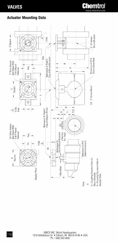
NIBCO INC. World Headquarters 1516 Middlebury St. • Elkhart, IN 46516-4740 • USA
Ph: 1.800.343.5455
www.chemtrol.com
110
Actuator Mounting Data
ValVEs

www.chemtrol.com
NIBCO INC. World Headquarters 1516 Middlebury St. • Elkhart, IN 46516-4740 • USA
Ph: 1.800.343.5455111
Actuator Mounting Data
ValVEs
Valv
e Si
ze
EF
GH
IJ
KL
MN
PR
ST
UV
W
B.C.
Sq.
B.C.
Sq.
Dia.
Flat
sB.
C.Sq
.B.
C.Sq
.
1/2
2.50
1.82
1.29
2.46
1.74
4.43
0.42
20.
280
0.90
4.89
0.75
1.40
0.99
2.60
1.84
1.34
0.57
0.28
1.13
0.88
0.26
3/4
2.50
1.82
1.29
2.46
1.74
4.43
0.61
30.
450
0.90
4.89
0.75
1.40
0.99
2.60
1.84
1.00
0.34
0.28
1.13
0.88
0.26
12.
501.
821.
292.
461.
744.
430.
613
0.45
00.
904.
890.
751.
400.
992.
601.
840.
710.
460.
281.
130.
880.
26
1 1/
4 / 1
1/2
3.00
2.46
1.74
3.02
2.14
7.22
0.73
80.
535
1.26
7.32
0.75
1.40
0.99
3.02
2.14
1.49
0.55
0.34
1.64
0.88
0.32
23.
002.
461.
743.
022.
147.
220.
988
0.75
51.
267.
320.
751.
400.
993.
022.
140.
750.
680.
341.
640.
880.
32
35.
002.
741.
945.
163.
659.
591.
240
0.90
0–
–1.
001.
841.
305.
163.
651.
250.
750.
321.
831.
020.
40
4/6
5.00
4.20
2.97
5.16
3.65
11.7
42.
090
1.26
0–
– 1.
001.
841.
305.
163.
651.
540.
500.
393.
031.
020.
40

NIBCO INC. World Headquarters 1516 Middlebury St. • Elkhart, IN 46516-4740 • USA
Ph: 1.800.343.5455
www.chemtrol.com
112
ValVEs
Actuator Mounting Data
1 A/A = Pneumatic Air to Air. A/SR = Pneumatic Air to Spring Return (fail-safe). E = Electric (motor driven).2 No adapter plate is used with this coupling. J represents distance above ref-erence point Y (top of mount bracket).
ball Valve Mount kit part numbers & coupling dimensions
Valve Size Actuator Type1
Drive Coupling Dimensions
A B C D E
1/2 A/A, A/SR & E 0.351 0.437 3.08 1.81 0.67
3/4 A/A, A/SR & E 0.351 0.437 2.51 1.24 0.44
1 A/A, A/SR & E 0.351 0.437 2.34 1.07 0.56
1 1/4 / 1 1/2
A/A & E 0.351 0.437 3.24 1.97 0.65
A/SR 0.430 0.549 3.28 1.97 0.65
2 A/A 0.430 0.549 2.64 1.33 0.78
A/SR 0.548 0.704 2.64 1.33 0.78
E 0.351 0.437 2.60 1.33 0.78
3 A/A & E 0.548 0.704 3.46 1.90 0.86
A/SR 0.666 0.882 2.46 1.90 0.86
4/6 A/A 0.666 0.882 3.44 1.88 0.59
A/SR 0.863 1.000 3.44 1.88 0.59
E 0.548 0.704 3.44 1.88 0.59
Valve Size Actuator Type1
Drive Coupling Dimensions
F G H J
1/2 A/A, A/SR & E 0.281 1.10 0.46 0.42
3/4 A/A, A/SR & E 0.451 1.10 0.46 0.42
1 A/A, A/SR & E 0.451 1.10 0.46 0.42
1 1/4 / 1 1/2
A/A & E 0.539 1.61 0.46 0.45
A/SR 0.539 1.61 0.57 0.49
2 A/A 0.761 1.61 0.50 0.46
A/SR 0.761 1.61 0.50 0.46
E 0.761 1.61 0.46 0.42
3 A/A & E 0.911 1.50 0.50 0.46
A/SR 0.911 1.50 0.50 0.462
4/6 A/A 1.266 1.75 0.50 0.40
A/SR 1.266 1.75 0.50 0.40
E 1.266 1.75 0.50 0.40
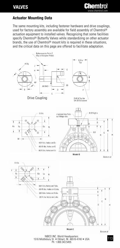
www.chemtrol.com
NIBCO INC. World Headquarters 1516 Middlebury St. • Elkhart, IN 46516-4740 • USA
Ph: 1.800.343.5455113
The same mounting kits, including fastener hardware and drive couplings, used for factory assembly are available for field assembly of Chemtrol® actuation equipment to installed valves. Recognizing that some facilities specify Chemtrol® Butterfly Valves while standardizing on other actuator brands, the use of Chemtrol® mount kits is required in these situations, and the critical data on this page are offered to facilitate adaptation.
Drive Coupling
Actuator Mounting Data
ValVEs
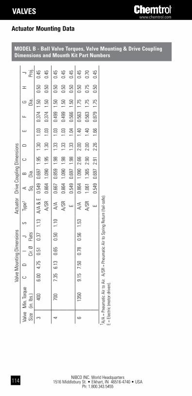
NIBCO INC. World Headquarters 1516 Middlebury St. • Elkhart, IN 46516-4740 • USA
Ph: 1.800.343.5455
www.chemtrol.com
114
ValVEs
Actuator Mounting Data
ModEl b - ball Valve torques, Valve Mounting & drive coupling dimensions and Mounth kit part numbers
Valv
e M
ount
ing
Dim
ensi
ons
Actu
ator
Driv
e Co
uplin
g Di
men
sion
s
Valv
e
Size
Min
. Tor
que
(in. l
bs.)
CD
I Ci
r. Ø
J Fl
ats
STy
pe1
A Sq.
B Dia.
CD
EF
G Dia.
HJ Proj
.
340
06.
004.
750.
510.
371.
13A/
A &
E0.
549
0.69
71.
951.
301.
030.
374
1.50
0.50
0.45
A/SR
0.86
41.
090
1.95
1.30
1.03
0.37
41.
500.
500.
45
470
07.
356.
130.
650.
501.
10A/
A0.
667
0.85
91.
981.
331.
030.
499
1.50
0.50
0.45
A/SR
0.86
41.
090
1.98
1.33
1.03
0.49
91.
500.
500.
45
E0.
549
0.69
71.
981.
331.
040.
566
1.50
0.50
0.45
613
509.
157.
500.
780.
561.
53A/
A0.
864
1.09
02.
662.
001.
400.
563
1.75
0.50
0.45
A/SR
1.06
11.
365
2.90
2.00
1.40
0.56
31.
750.
750.
70
E0.
549
0.69
72.
912.
261.
660.
879
1.75
0.50
0.45
1 A/A
= P
neum
atic
Air
to A
ir. A
/SR
= Pn
eum
atic
Air
to S
prin
g Re
turn
(fai
l-saf
e).
E
= El
ectri
c (m
otor
driv
en).

www.chemtrol.com
NIBCO INC. World Headquarters 1516 Middlebury St. • Elkhart, IN 46516-4740 • USA
Ph: 1.800.343.5455115
ModEl c - ball Valve torques, Valve Mounting & drive coupling dimensions and Mounth kit part numbers
Valv
e M
ount
ing
Dim
ensi
ons
Actu
ator
Driv
e Co
uplin
g Di
men
sion
sVa
lve
Si
zeM
in. T
orqu
e (in
. lbs
.)C
DI
Cir.
ØJ
Flat
sS
Type
1A Sq
.B Dia.
CD
EF
G Dia.
HJ Proj
.
2 2
245.
193.
940.
500.
371.
25A/
A0.
430
0.54
01.
260.
700.
530.
376
1.00
0.50
0.35
A/
SR &
E0.
548
0.69
21.
440.
750.
530.
376
1.25
0.63
0.53
2 1/
2A/
A0.
430
0.54
01.
260.
700.
530.
376
1.00
0.50
0.35
285
5.38
4.13
0.50
0.37
1.25
A/SR
0.
666
0.85
41.
560.
750.
530.
376
1.25
0.75
0.65
E0.
548
0.69
21.
440.
750.
530.
376
1.25
0.63
0.53
3 3
375.
584.
430.
500.
371.
15A/
A &
E0.
548
0.69
21.
440.
750.
530.
376
1.25
0.63
0.43
A/SR
0.66
60.
854
1.56
0.75
0.53
0.37
61.
250.
750.
55
4 4
206.
565.
310.
650.
501.
25A/
A &
E0.
548
0.69
21.
440.
750.
530.
501
1.25
0.63
0.53
A/SR
0.66
60.
854
1.56
0.75
0.53
0.50
11.
250.
750.
65
6A/
A0.
863
1.08
52.
131.
130.
660.
565
1.25
0.88
0.72
1261
8.34
7.09
0.78
0.56
1.25
A/SR
1.06
01.
390
2.31
1.00
0.56
0.56
51.
501.
191.
00E
0.66
60.
854
1.54
0.73
0.53
0.56
51.
250.
750.
63
8A/
A0.
863
1.08
52.
131.
130.
660.
565
1.25
0.88
0.72
1901
9.25
8.00
0.78
0.56
1.25
A/SR
1.06
01.
390
2.31
1.00
0.56
0.56
51.
501.
191.
00E
1/4"
key
1.37
33.
251.
370.
940.
565
1.50
1.63
1.56
10A/
A0.
863
1.08
52.
251.
250.
750.
753
1.50
0.88
0.75
2595
11.0
99.
841.
060.
751.
25A/
SR1.
413
1.86
22.
881.
250.
750.
753
2.00
1.56
1.25
E1/
4" k
ey1.
370
3.31
1.37
1.00
0.75
41.
751.
631.
56
Actuator Mounting Data
ValVEs
1 A/A
= P
neum
atic
Air
to A
ir. A
/SR
= Pn
eum
atic
Air
to S
prin
g Re
turn
(fai
l-saf
e).
E
= El
ectri
c (m
otor
driv
en).
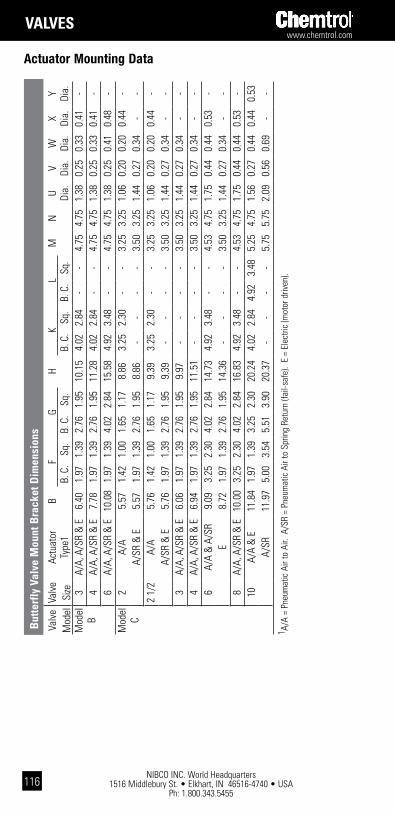
NIBCO INC. World Headquarters 1516 Middlebury St. • Elkhart, IN 46516-4740 • USA
Ph: 1.800.343.5455
www.chemtrol.com
116
ValVEs
1 A/A
= P
neum
atic
Air
to A
ir. A
/SR
= Pn
eum
atic
Air
to S
prin
g Re
turn
(fai
l-saf
e).
E =
Elec
tric
(mot
or d
riven
).
Valv
eVa
lve
Actu
ator
BF
GH
KL
MN
UV
WX
YM
odel
Size
Type
1B.
C.
Sq.
B. C
.Sq
.B.
C.
Sq.
B. C
.Sq
.Di
a.Di
a.Di
a.Di
a.Di
a.M
odel
B3
A/A,
A/S
R &
E6.
401.
971.
392.
761.
9510
.15
4.02
2.84
--
4.75
4.75
1.38
0.25
0.33
0.41
-4
A/A,
A/S
R &
E7.
781.
971.
392.
761.
9511
.28
4.02
2.84
--
4.75
4.75
1.38
0.25
0.33
0.41
-6
A/A,
A/S
R &
E10
.08
1.97
1.39
4.02
2.84
15.5
84.
923.
48-
-4.
754.
751.
380.
250.
410.
48-
Mod
elC
2A/
A5.
571.
421.
001.
651.
178.
863.
252.
30-
-3.
253.
251.
060.
200.
200.
44-
A/SR
& E
5.57
1.97
1.39
2.76
1.95
8.86
--
--
3.50
3.25
1.44
0.27
0.34
--
2 1/
2A/
A5.
761.
421.
001.
651.
179.
393.
252.
30-
-3.
253.
251.
060.
200.
200.
44-
A/SR
& E
5.76
1.97
1.39
2.76
1.95
9.39
--
--
3.50
3.25
1.44
0.27
0.34
--
3A/
A, A
/SR
& E
6.06
1.97
1.39
2.76
1.95
9.97
--
--
3.50
3.25
1.44
0.27
0.34
--
4A/
A, A
/SR
& E
6.94
1.97
1.39
2.76
1.95
11.5
1-
--
-3.
503.
251.
440.
270.
34-
-6
A/A
& A
/SR
9.09
3.25
2.30
4.02
2.84
14.7
34.
923.
48-
-4.
534.
751.
750.
440.
440.
53-
E8.
721.
971.
392.
761.
9514
.36
--
--
3.50
3.25
1.44
0.27
0.34
--
8A/
A, A
/SR
& E
10.0
03.
252.
304.
022.
8416
.83
4.92
3.48
--
4.53
4.75
1.75
0.44
0.44
0.53
-10
A/A
& E
11.8
41.
971.
393.
252.
3020
.24
4.02
2.84
4.92
3.48
5.25
4.75
1.56
0.27
0.44
0.44
0.53
A/SR
11.9
75.
003.
545.
513.
9020
.37
--
--
5.75
5.75
2.09
0.56
0.69
--
Actuator Mounting Data
but
terf
ly V
alve
Mou
nt b
rack
et d
imen
sion
s

www.chemtrol.com
NIBCO INC. World Headquarters 1516 Middlebury St. • Elkhart, IN 46516-4740 • USA
Ph: 1.800.343.5455117
ValVEs
For socket-end valves refer to the solvent cement joining instructions for PVC and CPVC, and the heat fusion joining instructions for PP and PVDF in the Chemtrol Thermoplastic Piping Technical Manual. For threaded-end valves usually one or two turns beyond hand-tight using a suitable strap wrench, if necessary, is suffi-cient. Do not overtighten threads. ANSI B1.20.1 defines hand tight as 4 to 5 threads for sizes through 2” and 5 to 6-3/4 threads for sizes greater than 2”.For flanged-end valves refer to the plastic flange joining instructions in the Chemtrol Thermoplastic Piping Technical Manual. CAUTION: Over tightening threads may result in damage to products.
When joining union-end valves, or when flanging end connectors, never make the joint to the end connectors while they are attached to the valve body. Remove the union nuts and end connectors from the valve cartridge first. Slide the union nut (smallest bore first) over the pipe or nipple and flange hub (when flanging) before making the joint to the end connector.After allowing the proper joint drying time, or cooling time in the case of PP and PVDF, end connections may be joined to the valve cartridge. O-rings provide the seal between the valve cartridge faces and the end connectors. Ensure that these O-rings are clean and in their proper grooves before slipping the valve cartridge between its end connectors. Slide the union nuts over the end connectors and screw onto the valve cartridge threads, no more than hand tight. Once the end con-nector engages the O-ring seal, no more than 1/8 to 1/4 turn of the union nut will fully compress the O-ring in its groove. CAUTION: Over tightening threads may result in damage to products.The pipe supports surrounding the valve must be loose and the adjoining piping must be well aligned with the valve. The union nuts cannot be expected to bend and/or stretch the adjoining pipe in order to allow the end connectors to make the required flush seal against the valve cartridge faces.3-Way Valve Seat adjustment - The seat-carrier in multiport and diverter valves is of the Model-A design, meaning that it is not fastened to the valve body with internal threads. Therefore, the union nut on the valve end with “ADJ” marked on the body serves the dual purpose of external adjustment for “squeeze” on the operating envelope within the cartridge, preventing leakage across the ball, as well as compression of the face-seal, preventing shell leakage at the cartridge face. Upon installation of multiport or diverter valves, with the handle parallel with the body and fully against the handle/body stop, tighten that union nut on the “ADJ” body end while minutely oper-ating the handle off the stop and back to the stop. The handle turning torque should become snug, but not excessive when the valve is properly adjusted for leak-free operation. If proper adjustment cannot be made by hand tighten-ing the union nut (valves larger than 1-1/2"), a suitable strap-wrench may be used.CAUTION: Over tightening threads may result in damage to products.Check Valves - Check valves should be installed at least four feet from the dis-charge side of a pump. Ball chatter and internal damage may result if fluid flow is too turbulent. Also, in keeping with good mechanical design practice, the upper threshold of fluid flow recommended from Chemtrol products is five feet per sec-ond.The valves may be installed vertically or horizontally (refer to the preceding page for minimum seating head requirements), but the molded-in flow arrow on the valve cartridge must be installed in the direction of the fluid flow such that reverse flow will be checked.
Valve Installation
ball and check Valves

NIBCO INC. World Headquarters 1516 Middlebury St. • Elkhart, IN 46516-4740 • USA
Ph: 1.800.343.5455
www.chemtrol.com
118
ValVEs
Chemtrol® Butterfly Valves are installed by bolting between two pipe flanges and may be mounted in any position. They are designed to be operated with pipes up to and including Schedule 80 wall thicknesses. If the I.D. of connecting pipe or equipment is smaller than Schedule 80, it will be necessary to chamfer the inside edge to avoid interference with the rotating butterfly disk.alignment - Excessive angular misalignment and/or axial displacement is detrimental to proper function of the companion flange face-seals built into the valves. For reference, ANSI/ASME B31.3, Code for Pressure Piping, Chemical Plant, and Petroleum Refinery Piping, stipulates that flange faces shall be aligned to the design plane (butterfly valve in this case) to within 1/16" in./ft. (0.5%) maximum measured across any diameter, and flange bolt holes shall be aligned to within 1/8" maximum offset.Insertion in System - The end flaps of the elastomeric seat (Model B) or the O-rings (Model C) serve as face-seals for the companion flanges to be mounted on each side of the butterfly valve. Other gaskets are not to be used. Flange clearance required for insertion is given in the bolting chart below. For installation between the flanges, the valve should be partially open, but not so far as to damage the edge of the disk on mating flanges. If the spacing between mating flanges is tight, the valve sealing surface should be coated with a lubricant to prevent distortion during installation. If more than soapy water is required, a non-hydrocarbon base material, such as silicone grease, may be used on EPDM face-seals. An oil-based lubricant, such as glycerin, is acceptable for FKM face-seals. Insert valve in desired position and install bolts with metal back-up washers (corresponding to ANSI B18.22.1, designated N – narrow washers previously known as SAE series washers) under both the bolt head and nut.
butterfly Valves
Valve Installation
Foot Valve Conversion - Foot valve screen housing assemblies are available to convert ball check valves to foot valves in the field. The assemblies are to be installed on the supply side of a standard Chemtrol Ball Check Valve, replacing the union nut and end connector. Foot valves are normally installed in an open tank or sump on the suction side of a pump. Its function is to screen debris from entering the pump.Vent Valve Conversion - The ball in a standard Chemtrol Ball Check Valve is intended by design to have a greater density than the fluid medium. When installed in the upright (seat down – arrow on body pointed in direction of nor-mal flow) to horizontal positions, gravitational force on the ball allows it to sink in the fluid and seal at the seat in order to prevent back-flow when directional flow is ceased (e.g., pump stops). However, the mechanical designer some-times wants air or gas to be vented from a piping system or vessel as fluid fills the system, but to check flow of fluid beyond the vent tube. As fluid is evacuat-ed from the system or vessel, the vent valve must open to prevent formation of a vacuum. The field conversion of the check valve to the venting function requires the replacement of the standard ball with a polypropylene ball, which will float in water or fluids of greater density. A vent valve must be installed in the inverted vertical position (seat up – arrow on body pointed in opposite direction of normal venting). The floater ball must also be chemically resistant to the medium. Failure to follow these instructions may cause stress cracking to the polypropylene ball (e.g., bleach, concentrated sulfuric or nitric acids).
ball and check Valves cont...

www.chemtrol.com
NIBCO INC. World Headquarters 1516 Middlebury St. • Elkhart, IN 46516-4740 • USA
Ph: 1.800.343.5455119
ValVEs
Note: Bolt size x washer OD – 1/2", 1.092"; 5/8", 1.342"; 3/4", 1.499"; 7/8", 1.780".Bolting - Snug up the bolts finger-tight so that the circumference of the inside bore of each companion flange evenly touches the face-seals of the butterfly valve. Make sure the valve is properly aligned before proceeding. Then, use of a torque wrench for pulling on the nuts is suggested for actual bolt tightening. It is critical that bolts be equally tightened in a sequential pattern diametrically opposed to each other, and that the final recommended bolt torque be accomplished through a minimum of three progressive stages of tightening. The recommended progressive tightening pattern and the final torque levels are shown on the following chart and diagram:
Valve Installation
Valve Flange Flange Bolt Bolts Recommended Size Clearance Clearance Diameter Required Bolt Torque2
(Nom.) Model B (in.) Model C (in.) (in.) (No.) (Ft.-Lbs.) * 2 - 1.69 5/8 4 20-30 * 2 1/2 - 1.81 5/8 4 20-30 3 2.00 1.81 5/8 4 or 8 1 20-30 4 2.25 2.06 5/8 8 20-30 6 2.81 2.19 3/4 8 33-50 * 8 - 2.38 3/4 8 33-50 * 10 - 2.69 7/8 12 53-75
* Available in Model C only.1 Four (4) bolt hole pattern for ANSI 150 flange pattern;
eight (8) bolt hole pattern for DIN standard flange pattern.2 Refers to well-lubricated bolts.
3 4
2
15 8
67
When valve installation is complete, open and close the valve to check for ease of operation and proper alignment. Caution: Do not allow the valve to support the weight of any related piping. Direct support is required when mechanical operators or actuators are utilized. Failure to follow these instructions may result in damage to products or property.
butterfly Valves cont...
Valve repair should only be performed by qualified maintenance personnel. Contact the nearest Chemtrol distributor should further information be required.
ball Valves
Should a valve need repair, depressurize and drain the system on all sides of the valve. Loosen the valve union nuts and slide them back over the end connectors. To minimize downtime, it may be advisable to have a replacement valve cartridge ready to install in place of the one to be repaired. An advantage of the Chemtrol design is that the current model is interchangeable with all earlier models. Disassemble valve cartridge following the instructions provided with the valve.
Valve Maintenance

NIBCO INC. World Headquarters 1516 Middlebury St. • Elkhart, IN 46516-4740 • USA
Ph: 1.800.343.5455
www.chemtrol.com
120
ValVEs
butterfly Valves
Following testing and soon after commissioning of a system, if either the Model B or Model C valve develops a leak at the top bearing, the flange face-seal(s), and/or across the valve disk, the most likely cause of the leak would be inappropriate selection of the elastomeric seat and seals. In this case, check the NIBCO Chem-Guide for compatibility with the fluid medium. If there is leakage at the flange face-seal(s) only, further tightening of bolts will almost never stop any flange joint leak. Rather, the remedy is to disassemble the joint and reseat the flanges on the valve face-seals, being careful to follow the bolting paragraph under the butterfly valve installation instructions.After extended operation, if leakage should occur at the top bearing or across the valve disk of either the Model B or Model C valve, this is a likely cause of wear to the elastomeric seat and/or O-ring seals, requiring their replacement. In most cases, valve replacement may be less expensive than parts replacement. In fact, the Model C valve cannot be disassembled. Only the handle assembly and O-ring face-seals may be replaced. Otherwise, replacement of the entire Model C valve is recommended. When maintenance to a Model B valve is required, refer to the disassembly and reassembly instructions included with the valve.
• The manufacturer does NOT recommend running a thermoplastic piping system with velocity greater than 5 feet/sec.
• WARNING: Do NOT close a quarter turn valve quickly. This will create shock in the system and cause damage to property or personal injury.
• Installing thermoplastic piping components at temperatures at 40°F requires extra precaution in handling because the material may be at increased risk of impact damage.
• WARNING: Follow the recommended bolt tightening techniques, including sequence of tightening and final torque values, for flanges and butterfly valves because failure to do so will result in damage to the product.
• Do not allow primer or solvent cement to come in contact with the sealing face of valve end connectors or internal components of the valve.
• Valves must be installed with the molded-in flow arrow(s) on the valve cartridge facing in the direction of the fluid flow.
• To ensure comprehensive chemical compatibility, a piping system must take into consideration the chemical resistance of all system components, including, but not limited to, plastic components, solvent cements or thread pastes (if applicable), elastomeric seals, all valve components and lubricants. Testing under field conditions may be the best way to ensure selected materials will work in a particular application.
• Consult the Chemtrol Thermoplastic Piping Technical Manual for additional design and installation requirements for Chemtrol products.
Valve Maintenance
General Design and Installation Guidelines
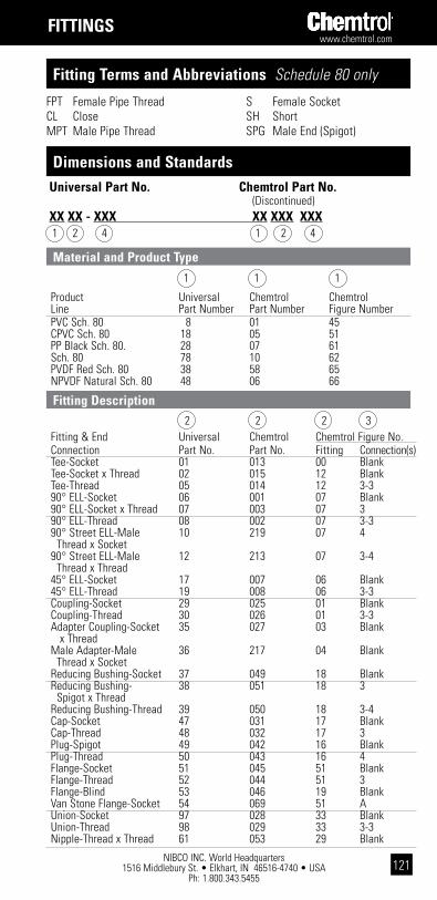
www.chemtrol.com
NIBCO INC. World Headquarters 1516 Middlebury St. • Elkhart, IN 46516-4740 • USA
Ph: 1.800.343.5455121
FPT Female Pipe ThreadCL CloseMPT Male Pipe Thread
S Female SocketSH ShortSPG Male End (Spigot)
Fitting terms and abbreviations Schedule 80 only
dimensions and standards
1 1 1 Product Universal Chemtrol Chemtrol Line Part Number Part Number Figure Number PVC Sch. 80 8 01 45 CPVC Sch. 80 18 05 51 PP Black Sch. 80. 28 07 61 Sch. 80 78 10 62 PVDF Red Sch. 80 38 58 65 NPVDF Natural Sch. 80 48 06 66
Material and product type
Universal part no. chemtrol part no. (Discontinued)xx xx - xxx xx xxx xxx 1 2 4 1 2 4
Fitting description 2 2 2 3 Fitting & End Universal Chemtrol Chemtrol Figure No. Connection Part No. Part No. Fitting Connection(s) Tee-Socket 01 013 00 Blank Tee-Socket x Thread 02 015 12 Blank Tee-Thread 05 014 12 3-3 90° ELL-Socket 06 001 07 Blank 90° ELL-Socket x Thread 07 003 07 3 90° ELL-Thread 08 002 07 3-3 90° Street ELL-Male 10 219 07 4 Thread x Socket 90° Street ELL-Male 12 213 07 3-4 Thread x Thread 45° ELL-Socket 17 007 06 Blank 45° ELL-Thread 19 008 06 3-3 Coupling-Socket 29 025 01 Blank Coupling-Thread 30 026 01 3-3 Adapter Coupling-Socket 35 027 03 Blank x Thread Male Adapter-Male 36 217 04 Blank Thread x Socket Reducing Bushing-Socket 37 049 18 Blank Reducing Bushing- 38 051 18 3 Spigot x Thread Reducing Bushing-Thread 39 050 18 3-4 Cap-Socket 47 031 17 Blank Cap-Thread 48 032 17 3 Plug-Spigot 49 042 16 Blank Plug-Thread 50 043 16 4 Flange-Socket 51 045 51 Blank Flange-Thread 52 044 51 3 Flange-Blind 53 046 19 Blank Van Stone Flange-Socket 54 069 51 A Union-Socket 97 028 33 Blank Union-Thread 98 029 33 3-3 Nipple-Thread x Thread 61 053 29 Blank
Fittings
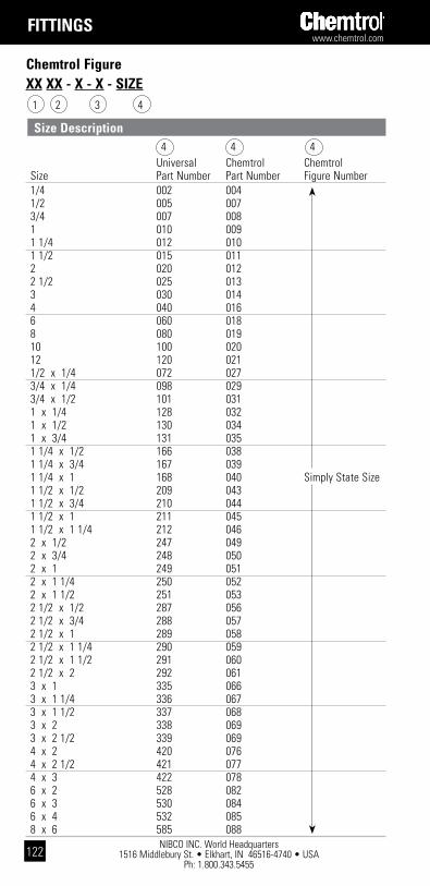
NIBCO INC. World Headquarters 1516 Middlebury St. • Elkhart, IN 46516-4740 • USA
Ph: 1.800.343.5455
www.chemtrol.com
122
chemtrol Figurexx xx - x - x - siZE 1 2 3 4
Fittings
size description 4 4 4 Universal Chemtrol Chemtrol Size Part Number Part Number Figure Number 1/4 002 004 1/2 005 007 3/4 007 008 1 010 009 1 1/4 012 010 1 1/2 015 011 2 020 012 2 1/2 025 013 3 030 014 4 040 016 6 060 018 8 080 019 10 100 020 12 120 021 1/2 x 1/4 072 027 3/4 x 1/4 098 029 3/4 x 1/2 101 031 1 x 1/4 128 032 1 x 1/2 130 034 1 x 3/4 131 035 1 1/4 x 1/2 166 038 1 1/4 x 3/4 167 039 1 1/4 x 1 168 040 Simply State Size 1 1/2 x 1/2 209 043 1 1/2 x 3/4 210 044 1 1/2 x 1 211 045 1 1/2 x 1 1/4 212 046 2 x 1/2 247 049 2 x 3/4 248 050 2 x 1 249 051 2 x 1 1/4 250 052 2 x 1 1/2 251 053 2 1/2 x 1/2 287 056 2 1/2 x 3/4 288 057 2 1/2 x 1 289 058 2 1/2 x 1 1/4 290 059 2 1/2 x 1 1/2 291 060 2 1/2 x 2 292 061 3 x 1 335 066 3 x 1 1/4 336 067 3 x 1 1/2 337 068 3 x 2 338 069 3 x 2 1/2 339 069 4 x 2 420 076 4 x 2 1/2 421 077 4 x 3 422 078 6 x 2 528 082 6 x 3 530 084 6 x 4 532 085 8 x 6 585 088

www.chemtrol.com
NIBCO INC. World Headquarters 1516 Middlebury St. • Elkhart, IN 46516-4740 • USA
Ph: 1.800.343.5455123
pVc Fittings
Nominal Universal Ctn. Approx. Dim. Size Part No. Qty. Lbs./Ea. N 1/4 829-002 25 0.05 0.12 1/2 829-005 50 0.09 0.25 3/4 829-007 50 0.13 0.25 1 829-010 40 0.14 0.25 1 1/4 829-012 25 0.22 0.25 1 1/2 829-015 20 0.29 0.25 2 829-020 25 0.42 0.25 2 1/2 829-025 5 0.68 0.20 3 829-030 12 1.05 0.19 4 829-040 10 1.83 0.19 6 829-060 4 3.56 0.25 8 829-080 2 8.69 0.2510 829-100 1 13.88 0.3812 829-120 1 22.69 0.50
Couplings
4501-R Reducing socket coupling (s x s)
Nominal Universal Ctn. Approx. Dim. Size Part No. Qty. Lbs./Ea. N 3/4 x 1/2 829-101 25 0.12 0.44 1 x 1/2 829-130 25 0.18 0.67 1 x 3/4 829-131 25 0.19 0.55 1 1/4 x 3/4 829-167 25 0.26 0.72 1 1/4 x 1 829-168 10 0.27 0.60 1 1/2 x 1/2 829-209 10 0.31 0.81 1 1/2 x 3/4 829-210 10 0.31 0.76 1 1/2 x 1 829-211 10 0.33 0.63 1 1/2 x 1 1/4 829-212 10 0.35 0.51 2 x 1 829-249 10 0.44 0.75 2 x 1 1/2 829-251 10 0.50 0.50 3 x 2 829-338 5 1.00 1.24 4 x 2 829-420 5 1.59 1.59 4 x 3 829-422 5 1.88 1.20Other Reducing Couplings are produced by solvent cementing appropriate Reducer Bushings into Socket Couplings. They may be ordered as factory fabrications or may be assembled in the field.
4501 socket coupling (s x s)
Chemtrol Fig. No.

NIBCO INC. World Headquarters 1516 Middlebury St. • Elkhart, IN 46516-4740 • USA
Ph: 1.800.343.5455
www.chemtrol.com
124
pVc Fittings
Chemtrol Fig. No.
Nominal Universal Ctn. Approx. Dim. Size Part No. Qty. Lbs./Ea. L 3/4 x 1/2 830-101 25 0.14 2.34 1 x 1/2 830-130 25 0.20 2.70 1 x 3/4 830-131 25 0.18 2.70 1 1/4 x 3/4 830-167 10 0.29 3.00 1 1/4 x 1 830-168 10 0.31 3.00 1 1/2 x 3/4 830-210 10 0.35 3.16 1 1/2 x 1 830-211 10 0.38 3.16 1 1/2 x 1 1/4 830-212 10 0.40 3.16 2 x 1 830-249 10 0.50 3.40 2 x 1 1/2 830-251 10 0.56 3.40 3 x 2 830-338 5 1.15 4.66 4 x 2 830-420 5 1.79 5.38 4 x 3 830-422 5 2.11 5.38Other Reducing Couplings are produced by solvent cementing appropriate Reducer Bushings into Socket Couplings. They may be ordered as factory fabrications or may be assembled in the field.
4501-3-3-R Reducing thread coupling (Fpt x Fpt)
4501-3-3 thread coupling (Fpt x Fpt)
Nominal Universal Ctn. Approx. Dim. Size Part No. Qty. Lbs./Ea. L 1/4 830-002 25 0.06 1.41 1/2 830-005 25 0.09 2.03 3/4 830-007 25 0.14 2.28 1 830-010 25 0.23 2.53 1 1/4 830-012 10 0.33 2.78 1 1/2 830-015 10 0.41 3.03 2 830-020 10 0.60 3.28 2 1/2 830-025 5 0.86 3.76 3 830-030 5 1.22 4.00 4 830-040 5 2.13 4.75
Couplings

www.chemtrol.com
NIBCO INC. World Headquarters 1516 Middlebury St. • Elkhart, IN 46516-4740 • USA
Ph: 1.800.343.5455125
pVc Fittings
Nominal Universal Ctn. Approx. Dim. Size Part No. Qty. Lbs./Ea. OM 1/2 836-005 25 0.04 0.94 3/4 836-007 25 0.06 0.97 1 836-010 25 0.10 1.15 1 1/4 836-012 10 0.14 1.12 1 1/2 836-015 10 0.19 1.12 2 836-020 10 0.27 1.20 2 1/2 836-025 5 0.50 1.89 3 836-030 5 0.79 1.99 4 836-040 5 1.30 2.09
Adapters
4503 Female adapter coupling (s x Fpt)
Chemtrol Fig. No.
4504 Male adapter (s x Mpt)
Nominal Universal Ctn. Approx. Dim. Size Part No. Qty. Lbs./Ea. O 1/4 835-002 15 0.04 0.77 1/2 835-005 25 0.09 1.14 3/4 835-007 25 0.14 1.27 1 835-010 20 0.21 1.39 1 1/4 835-012 10 0.30 1.52 1 1/2 835-015 10 0.38 1.64 2 835-020 10 0.56 1.77 2 1/2 835-025 5 0.77 1.98 3 835-030 5 1.15 2.10 4 835-040 5 1.95 2.47

NIBCO INC. World Headquarters 1516 Middlebury St. • Elkhart, IN 46516-4740 • USA
Ph: 1.800.343.5455
www.chemtrol.com
126
pVc Fittings
Chemtrol Fig. No.
4501-3-3 thread coupling (Fpt x Fpt)
Nominal Universal Ctn. Approx. Dim. Dim. Dim.Size Part No. Qty. Lbs./Ea. A B C1/2 15 0.20 2.00 2.75 1.383/4 Use 15 0.35 2.38 2.88 1.631 Figure 15 0.40 2.56 2.88 1.881 1/4 No. & 10 0.55 3.25 3.00 2.631 1/2 Nom. 10 0.65 3.25 3.00 2.632 Size 5 1.15 4.38 3.25 3.253 5 2.10 6.00 3.63 4.50
Note: Gasket is EPDM and nut is self-tightening left hand thread.
For complete technical information and more, refer to our website at www.chemtrol.com.
Adapters

www.chemtrol.com
NIBCO INC. World Headquarters 1516 Middlebury St. • Elkhart, IN 46516-4740 • USA
Ph: 1.800.343.5455127
pVc Fittings
Nominal Universal Ctn. Approx. Dim. Size Part No. Qty. Lbs./Ea. G 1/4 806-002 25 0.01 0.33 1/2 806-005 50 0.11 0.52 3/4 806-007 50 0.16 0.69 1 806-010 50 0.21 0.75 1 1/4 806-012 25 0.25 0.92 1 1/2 806-015 25 0.38 1.06 2 806-020 25 0.57 1.27 2 1/2 806-025 5 1.16 1.53 3 806-030 12 1.50 1.84 4 806-040 12 3.08 2.34 6 806-060 4 8.03 3.50 8 806-080 2 15.25 4.5610 806-100 1 27.70 5.7512 806-120 1 43.90 6.891
Elbows
4507 socket 90° Elbow (s x s)
Chemtrol Fig. No.
4507-3 socket x thread 90° Elbow (s x Fpt)
Nominal Universal Ctn. Approx. Dim. Dim. Size Part No. Qty. Lbs./Ea. G H 1/2 807-005 10 0.12 0.52 1.41 3/4 807-007 10 0.17 0.69 1.71 1 807-010 10 0.28 0.75 1.89 1 1/4 807-012 10 0.33 0.92 2.18 1 1/2 807-015 10 0.55 1.06 2.45 2 807-020 10 0.82 1.27 2.78
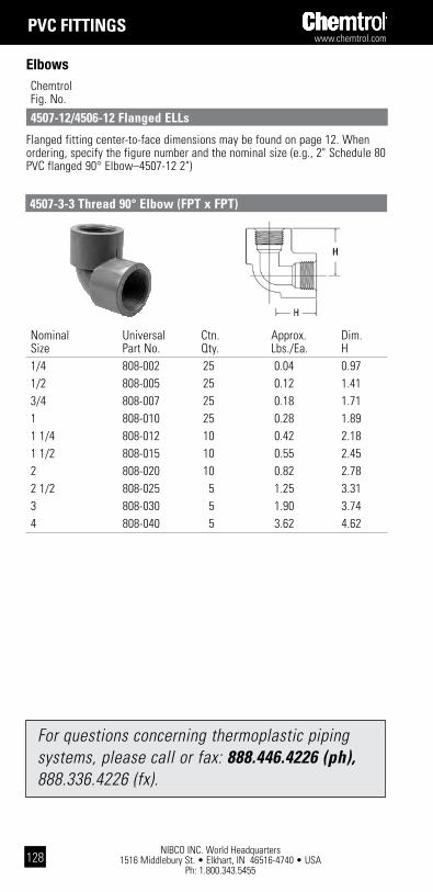
NIBCO INC. World Headquarters 1516 Middlebury St. • Elkhart, IN 46516-4740 • USA
Ph: 1.800.343.5455
www.chemtrol.com
128
pVc Fittings
Flanged fitting center-to-face dimensions may be found on page 12. When ordering, specify the figure number and the nominal size (e.g., 2" Schedule 80 PVC flanged 90° Elbow–4507-12 2")
Chemtrol Fig. No.
4507-12/4506-12 Flanged Ells
Elbows
4507-3-3 thread 90° Elbow (Fpt x Fpt)
Nominal Universal Ctn. Approx. Dim. Size Part No. Qty. Lbs./Ea. H 1/4 808-002 25 0.04 0.97 1/2 808-005 25 0.12 1.41 3/4 808-007 25 0.18 1.71 1 808-010 25 0.28 1.89 1 1/4 808-012 10 0.42 2.18 1 1/2 808-015 10 0.55 2.45 2 808-020 10 0.82 2.78 2 1/2 808-025 5 1.25 3.31 3 808-030 5 1.90 3.74 4 808-040 5 3.62 4.62
For questions concerning thermoplastic piping systems, please call or fax: 888.446.4226 (ph), 888.336.4226 (fx).

www.chemtrol.com
NIBCO INC. World Headquarters 1516 Middlebury St. • Elkhart, IN 46516-4740 • USA
Ph: 1.800.343.5455129
Nominal Universal Ctn. Approx. Dim. Size Part No. Qty. Lbs./Ea. J 1/4 817-002 15 0.03 0.18 1/2 817-005 25 0.04 0.26 3/4 817-007 25 0.14 0.33 1 817-010 25 0.15 0.37 1 1/4 817-012 10 0.24 0.43 1 1/2 817-015 10 0.31 0.47 2 817-020 10 0.48 0.61 2 1/2 817-025 5 0.93 0.68 3 817-030 6 1.23 0.78 4 817-040 6 2.46 1.02 6 817-060 4 6.21 1.75 8 817-080 2 13.03 2.2210 817-100 1 19.70 2.6112 817-120 1 32.70 3.08
4506 socket 45° Elbow (s x s)
pVc Fittings
Elbows Chemtrol Fig. No.
Nominal Universal Ctn. Approx. Dim. Size Part No. Qty. Lbs./Ea. K 1/4 819-002 15 0.04 0.82 1/2 819-005 25 0.11 1.15 3/4 819-007 25 0.13 1.35 1 819-010 25 0.25 1.51 1 1/4 819-012 10 0.35 1.70 1 1/2 819-015 10 0.48 1.86 2 819-020 10 0.71 2.13 2 1/2 819-025 5 1.03 2.46 3 819-030 6 1.53 2.69 4 819-040 6 2.52 3.30
4506-3-3 thread 45° Elbow (Fpt x Fpt)

NIBCO INC. World Headquarters 1516 Middlebury St. • Elkhart, IN 46516-4740 • USA
Ph: 1.800.343.5455
www.chemtrol.com
130
pVc Fittings
Chemtrol Fig. No.
Tees
Nominal Universal Ctn. Approx. Dim. Dim. Dim. Size Part No. Qty. Lbs./Ea. G G I 1/4 801-002 25 0.05 0.33 0.33 0.33 1/2 801-005 50 0.11 0.52 0.52 0.52 3/4 801-007 50 0.17 0.69 0.69 0.69 1 801-810 25 0.25 0.75 0.75 0.75 1 1/4 801-012 10 0.48 0.92 0.92 0.92 1 1/2 801-015 10 0.52 1.06 1.06 1.06 2 801-020 20 0.97 1.27 1.27 1.27 2 1/2 801-025 5 1.50 1.53 1.53 1.53 3 801-030 12 2.00 1.84 1.84 1.84 4 801-040 10 3.54 2.34 2.34 2.34 6 801-060 4 10.47 3.50 3.50 3.50 8 801-080 1 20.57 4.56 4.56 4.5610 801-100 1 35.40 5.75 5.75 5.7512 801-120 1 58.40 6.89 6.89 6.894511
4511 socket tee (s x s x s)
4511-12 Flanged tee
Flanged fitting center-to-face dimensions may be found on page 12. When ordering, specify the figure number and the nominal size (e.g., 2" Schedule 80 PVC flanged tee–4511-12 2")
4511-R Reducing socket tee (s x s x s) Nominal Universal Ctn. Approx. Dim. Dim. Dim. Size Part No. Qty. Lbs./Ea. G G I 3/4 x 3/4 x 1/2 801-101 25 0.18 0.52 0.52 0.62 1 x 1 x 1/2 801-130 10 0.24 0.53 0.53 0.73 1 x 1 x 3/4 801-131 10 0.26 0.63 0.63 0.74 1 1/2 x 1 1/2 x 3/4 801-210 10 0.48 0.67 0.67 1.05 1 1/2 x 1 1/2 x 1 801-211 10 0.52 0.77 0.77 1.04 2 x 2 x 1/2 801-247 10 0.61 0.61 0.61 1.30 2 x 2 x 3/4 801-248 10 0.65 0.71 0.71 1.30 2 x 2 x 1 801-249 10 0.69 0.81 0.81 1.30 2 x 2 x 1 1/2 801-251 10 0.83 1.08 1.08 1.30 3 x 3 x 2 801-338 5 1.73 1.37 1.37 1.86 4 x 4 x 2 801-420 5 2.79 1.42 1.42 2.36 4 x 4 x 3 801-422 5 3.33 1.90 1.90 2.38 6 x 6 x 4 801-532 4 7.29 2.60 2.60 3.56
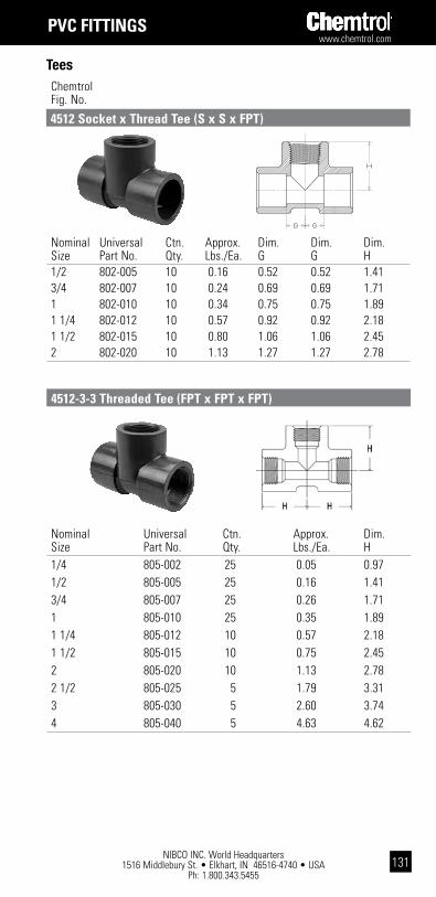
www.chemtrol.com
NIBCO INC. World Headquarters 1516 Middlebury St. • Elkhart, IN 46516-4740 • USA
Ph: 1.800.343.5455131
Nominal Universal Ctn. Approx. Dim. Dim. Dim. Size Part No. Qty. Lbs./Ea. G G H 1/2 802-005 10 0.16 0.52 0.52 1.41 3/4 802-007 10 0.24 0.69 0.69 1.71 1 802-010 10 0.34 0.75 0.75 1.89 1 1/4 802-012 10 0.57 0.92 0.92 2.18 1 1/2 802-015 10 0.80 1.06 1.06 2.45 2 802-020 10 1.13 1.27 1.27 2.78
pVc Fittings
Tees Chemtrol Fig. No.
4512 socket x thread tee (s x s x Fpt)
Nominal Universal Ctn. Approx. Dim. Size Part No. Qty. Lbs./Ea. H 1/4 805-002 25 0.05 0.97 1/2 805-005 25 0.16 1.41 3/4 805-007 25 0.26 1.71 1 805-010 25 0.35 1.89 1 1/4 805-012 10 0.57 2.18 1 1/2 805-015 10 0.75 2.45 2 805-020 10 1.13 2.78 2 1/2 805-025 5 1.79 3.31 3 805-030 5 2.60 3.74 4 805-040 5 4.63 4.62
4512-3-3 threaded tee (Fpt x Fpt x Fpt)
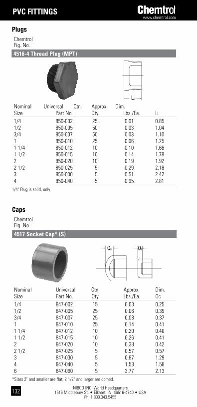
NIBCO INC. World Headquarters 1516 Middlebury St. • Elkhart, IN 46516-4740 • USA
Ph: 1.800.343.5455
www.chemtrol.com
132
pVc Fittings
Chemtrol Fig. No.
Plugs
Nominal Universal Ctn. Approx. Dim. Size Part No. Qty. Lbs./Ea. LL
1/4 850-002 25 0.01 0.85 1/2 850-005 50 0.03 1.04 3/4 850-007 50 0.03 1.10 1 850-010 25 0.06 1.25 1 1/4 850-012 10 0.10 1.66 1 1/2 850-015 10 0.14 1.78 2 850-020 10 0.19 1.92 2 1/2 850-025 5 0.29 2.18 3 850-030 5 0.51 2.42 4 850-040 5 0.95 2.811/4" Plug is solid, only
4516-4 thread plug (Mpt)
Chemtrol Fig. No.
Caps
4517 socket cap* (s)
Nominal Universal Ctn. Approx. Dim. Size Part No. Qty. Lbs./Ea. OC
1/4 847-002 15 0.03 0.25 1/2 847-005 25 0.06 0.39 3/4 847-007 25 0.08 0.37 1 847-010 25 0.14 0.41 1 1/4 847-012 10 0.20 0.40 1 1/2 847-015 10 0.26 0.41 2 847-020 10 0.38 0.42 2 1/2 847-025 5 0.57 0.57 3 847-030 5 0.87 1.29 4 847-040 5 1.53 1.58 6 847-060 5 3.77 2.13*Sizes 2" and smaller are flat; 2 1/2" and larger are domed.
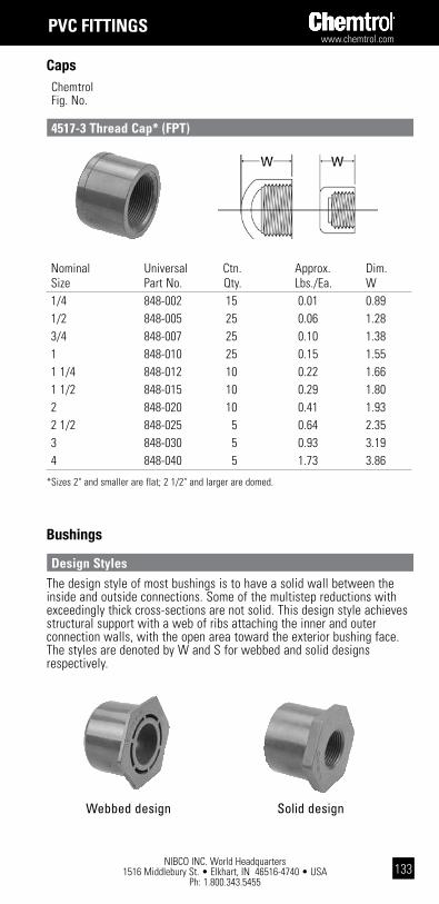
www.chemtrol.com
NIBCO INC. World Headquarters 1516 Middlebury St. • Elkhart, IN 46516-4740 • USA
Ph: 1.800.343.5455133
Nominal Universal Ctn. Approx. Dim. Size Part No. Qty. Lbs./Ea. W 1/4 848-002 15 0.01 0.89 1/2 848-005 25 0.06 1.28 3/4 848-007 25 0.10 1.38 1 848-010 25 0.15 1.55 1 1/4 848-012 10 0.22 1.66 1 1/2 848-015 10 0.29 1.80 2 848-020 10 0.41 1.93 2 1/2 848-025 5 0.64 2.35 3 848-030 5 0.93 3.19 4 848-040 5 1.73 3.86
*Sizes 2" and smaller are flat; 2 1/2" and larger are domed.
4517-3 thread cap* (Fpt)
Caps Chemtrol Fig. No.
pVc Fittings
Bushings
The design style of most bushings is to have a solid wall between the inside and outside connections. Some of the multistep reductions with exceedingly thick cross-sections are not solid. This design style achieves structural support with a web of ribs attaching the inner and outer connection walls, with the open area toward the exterior bushing face. The styles are denoted by W and S for webbed and solid designs respectively.
design styles
Webbed design Solid design
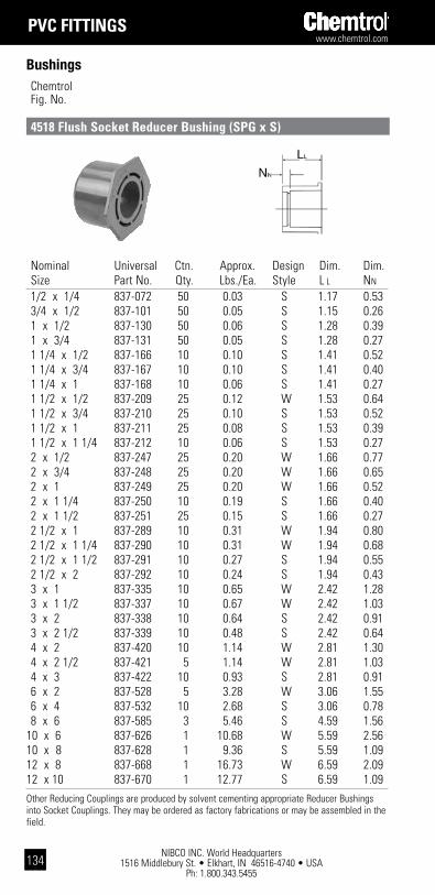
NIBCO INC. World Headquarters 1516 Middlebury St. • Elkhart, IN 46516-4740 • USA
Ph: 1.800.343.5455
www.chemtrol.com
134
Chemtrol Fig. No.
Bushings
4518 Flush socket Reducer bushing (spg x s)
pVc Fittings
Nominal Universal Ctn. Approx. Design Dim. Dim. Size Part No. Qty. Lbs./Ea. Style L L NN
1/2 x 1/4 837-072 50 0.03 S 1.17 0.53 3/4 x 1/2 837-101 50 0.05 S 1.15 0.26 1 x 1/2 837-130 50 0.06 S 1.28 0.39 1 x 3/4 837-131 50 0.05 S 1.28 0.27 1 1/4 x 1/2 837-166 10 0.10 S 1.41 0.52 1 1/4 x 3/4 837-167 10 0.10 S 1.41 0.40 1 1/4 x 1 837-168 10 0.06 S 1.41 0.27 1 1/2 x 1/2 837-209 25 0.12 W 1.53 0.64 1 1/2 x 3/4 837-210 25 0.10 S 1.53 0.52 1 1/2 x 1 837-211 25 0.08 S 1.53 0.39 1 1/2 x 1 1/4 837-212 10 0.06 S 1.53 0.27 2 x 1/2 837-247 25 0.20 W 1.66 0.77 2 x 3/4 837-248 25 0.20 W 1.66 0.65 2 x 1 837-249 25 0.20 W 1.66 0.52 2 x 1 1/4 837-250 10 0.19 S 1.66 0.40 2 x 1 1/2 837-251 25 0.15 S 1.66 0.27 2 1/2 x 1 837-289 10 0.31 W 1.94 0.80 2 1/2 x 1 1/4 837-290 10 0.31 W 1.94 0.68 2 1/2 x 1 1/2 837-291 10 0.27 S 1.94 0.55 2 1/2 x 2 837-292 10 0.24 S 1.94 0.43 3 x 1 837-335 10 0.65 W 2.42 1.28 3 x 1 1/2 837-337 10 0.67 W 2.42 1.03 3 x 2 837-338 10 0.64 S 2.42 0.91 3 x 2 1/2 837-339 10 0.48 S 2.42 0.64 4 x 2 837-420 10 1.14 W 2.81 1.30 4 x 2 1/2 837-421 5 1.14 W 2.81 1.03 4 x 3 837-422 10 0.93 S 2.81 0.91 6 x 2 837-528 5 3.28 W 3.06 1.55 6 x 4 837-532 10 2.68 S 3.06 0.78 8 x 6 837-585 3 5.46 S 4.59 1.5610 x 6 837-626 1 10.68 W 5.59 2.5610 x 8 837-628 1 9.36 S 5.59 1.0912 x 8 837-668 1 16.73 W 6.59 2.0912 x 10 837-670 1 12.77 S 6.59 1.09Other Reducing Couplings are produced by solvent cementing appropriate Reducer Bushings into Socket Couplings. They may be ordered as factory fabrications or may be assembled in the field.
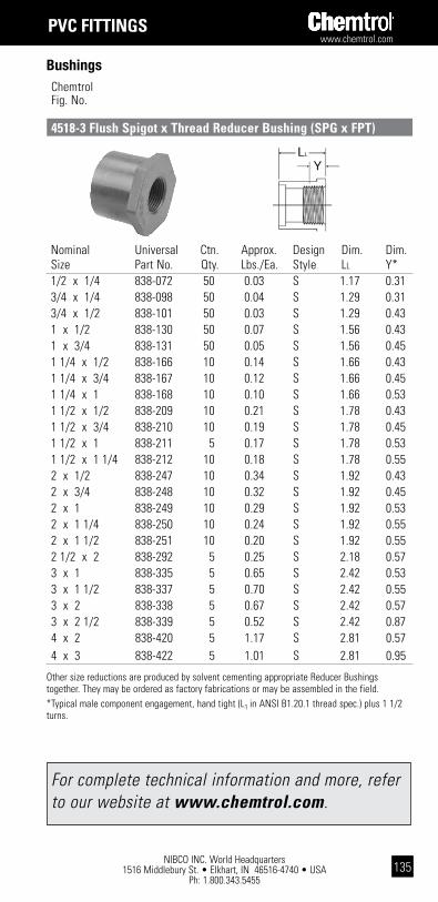
www.chemtrol.com
NIBCO INC. World Headquarters 1516 Middlebury St. • Elkhart, IN 46516-4740 • USA
Ph: 1.800.343.5455135
4518-3 Flush spigot x thread Reducer bushing (spg x Fpt)
Bushings Chemtrol Fig. No.
pVc Fittings
Nominal Universal Ctn. Approx. Design Dim. Dim. Size Part No. Qty. Lbs./Ea. Style LL Y* 1/2 x 1/4 838-072 50 0.03 S 1.17 0.31 3/4 x 1/4 838-098 50 0.04 S 1.29 0.31 3/4 x 1/2 838-101 50 0.03 S 1.29 0.43 1 x 1/2 838-130 50 0.07 S 1.56 0.43 1 x 3/4 838-131 50 0.05 S 1.56 0.45 1 1/4 x 1/2 838-166 10 0.14 S 1.66 0.43 1 1/4 x 3/4 838-167 10 0.12 S 1.66 0.45 1 1/4 x 1 838-168 10 0.10 S 1.66 0.53 1 1/2 x 1/2 838-209 10 0.21 S 1.78 0.43 1 1/2 x 3/4 838-210 10 0.19 S 1.78 0.45 1 1/2 x 1 838-211 5 0.17 S 1.78 0.53 1 1/2 x 1 1/4 838-212 10 0.18 S 1.78 0.55 2 x 1/2 838-247 10 0.34 S 1.92 0.43 2 x 3/4 838-248 10 0.32 S 1.92 0.45 2 x 1 838-249 10 0.29 S 1.92 0.53 2 x 1 1/4 838-250 10 0.24 S 1.92 0.55 2 x 1 1/2 838-251 10 0.20 S 1.92 0.55 2 1/2 x 2 838-292 5 0.25 S 2.18 0.57 3 x 1 838-335 5 0.65 S 2.42 0.53 3 x 1 1/2 838-337 5 0.70 S 2.42 0.55 3 x 2 838-338 5 0.67 S 2.42 0.57 3 x 2 1/2 838-339 5 0.52 S 2.42 0.87 4 x 2 838-420 5 1.17 S 2.81 0.57 4 x 3 838-422 5 1.01 S 2.81 0.95
Other size reductions are produced by solvent cementing appropriate Reducer Bushings together. They may be ordered as factory fabrications or may be assembled in the field.*Typical male component engagement, hand tight (L1 in ANSI B1.20.1 thread spec.) plus 1 1/2 turns.
For complete technical information and more, refer to our website at www.chemtrol.com.

NIBCO INC. World Headquarters 1516 Middlebury St. • Elkhart, IN 46516-4740 • USA
Ph: 1.800.343.5455
www.chemtrol.com
136
Chemtrol Fig. No.
Bushings
4518-3-4 Flush thread Reducer bushing (Mpt x Fpt)
pVc Fittings
Y
LL
Nominal Universal Ctn. Approx. Design Dim. Dim. Size Part No. Qty. Lbs./Ea. Style L L Y* 1/2 x 1/4 839-072 50 0.02 S 0.93 0.25 3/4 x 1/4 839-098 50 0.03 S 0.95 0.25 3/4 x 1/2 839-101 50 0.02 S 0.95 0.25 1 x 1/2 839-130 50 0.05 S 1.24 0.38 1 x 3/4 839-131 50 0.03 S 1.24 0.38 1 1/4 x 1/2 839-166 10 0.10 S 1.27 0.38 1 1/4 x 3/4 839-167 10 0.09 S 1.27 0.38 1 1/4 x 1 839-168 10 0.07 S 1.27 0.38 1 1/2 x 1/2 839-209 10 0.20 S 1.28 0.38 1 1/2 x 3/4 839-210 10 0.14 S 1.28 0.38 1 1/2 x 1 839-211 10 0.12 S 1.28 0.38 1 1/2 x 1 1/4 839-212 10 0.08 S 1.28 0.38 2 x 1/2 839-247 10 0.32 S 1.32 0.38 2 x 3/4 839-248 10 0.30 S 1.32 0.38 2 x 1 839-249 10 0.28 S 1.32 0.38 2 x 1 1/4 839-250 10 0.22 S 1.32 0.38 2 x 1 1/2 839-251 10 0.18 S 1.32 0.38 2 1/2 x 2 839-292 5 0.21 S 2.18 0.57 3 x 1 1/2 839-337 5 0.58 S 2.42 0.55 3 x 2 839-338 5 0.56 S 2.42 0.57 3 x 2 1/2 839-339 5 0.45 S 2.42 0.87 4 x 2 839-420 5 1.09 S 2.81 0.57 4 x 3 839-422 5 0.81 S 2.81 0.95
Other size reductions are produced by solvent cementing appropriate Reducer Bushings together. They may be ordered as factory fabrications or may be assembled in the field.*Typical male component engagement, hand tight (L1 in ANSI B1.20.1 thread spec.) plus 1 1/2 turns.

www.chemtrol.com
NIBCO INC. World Headquarters 1516 Middlebury St. • Elkhart, IN 46516-4740 • USA
Ph: 1.800.343.5455137
Nominal Universal Ctn. Approx. Dim. Dim.
Size Part No. Qty. Lbs./Ea. G N 1/2 851-H05 10 0.21 0.54 0.20 3/4 851-H07 10 0.31 0.61 0.17 1 851-H10 24 0.41 0.68 0.18 1 1/4 851-H12 10 0.53 0.73 0.20 1 1/2 851-H15 12 0.68 0.82 0.23 2 851-H20 12 0.96 0.92 0.27 2 1/2 851-H25 5 1.61 1.02 0.20 3 851-H30 10 2.16 1.13 0.29 4 851-H40 10 2.98 1.24 0.32 6 851-H60 5 4.44 1.36 0.31 8 851-H80 2 9.12 1.50 0.35Reducing Flanges are produced by solvent cementing Reducer Bushings into Socket Flanges. They may be ordered as factory fabrications or may be assembled in the field.
Nominal Universal Ctn. Approx. Dim. Dim. Size Part No. Qty. Lbs./Ea. G OF
1/2 852-H05 10 0.21 0.54 0.88 3/4 852-H07 10 0.30 0.61 0.91 1 852-H10 10 0.40 0.68 1.08 1 1/4 852-H12 10 0.50 0.73 1.11 1 1/2 852-H15 12 0.65 0.82 1.12 2 852-H20 10 0.90 0.92 1.18 2 1/2 852-H25 5 1.50 1.02 1.42 3 852-H30 5 1.93 1.13 1.55 4 852-H40 5 2.80 1.24 1.67Reducing Flanges are produced by solvent cementing Reducer Bushings into Socket Flanges. They may be ordered as factory fabrications or may be assembled in the field.
4551-h socket Flange (s), one-piece (solid)
Class 150 Flanges
Chemtrol Fig. No.
pVc Fittings
For flange dimensions that comply with ANSI B16.5, 150 lb., steel flanges, see Reference Data on following pages.
4551-h-3 thread Flange (Fpt), one-piece (solid)
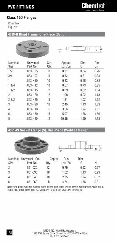
NIBCO INC. World Headquarters 1516 Middlebury St. • Elkhart, IN 46516-4740 • USA
Ph: 1.800.343.5455
www.chemtrol.com
138
Chemtrol Fig. No.
Class 150 Flanges
4519-h blind Flange, one-piece (solid)
pVc Fittings
Nominal Universal Ctn. Approx. Dim. Dim. Size Part No. Qty. Lbs./Ea. G N 2 851-020 12 0.79 0.92 0.27 3 851-030 10 1.52 1.13 0.29 4 851-040 10 2.25 1.24 0.32 6 851-060 5 4.24 1.36 0.31Note: One-piece webbed flanges have oblong bolt holes which permit mating with ANSI B16.5, 150 lb.; BS 1560, class 150; ISO 2084, PN10; and DIN 2532, PN10 flanges.
Nominal Universal Ctn. Approx. Dim. Dim. Size Part No. Qty. Lbs./Ea. G OB
1/2 853-H05 10 0.21 0.54 0.76 3/4 853-H07 10 0.32 0.61 0.83 1 853-H10 10 0.43 0.68 0.88 1 1/4 853-H12 10 0.57 0.73 0.95 1 1/2 853-H15 12 0.69 0.82 1.04 2 853-H20 12 1.08 0.92 1.13 2 1/2 853-H25 5 1.81 1.02 1.22 3 853-H30 10 2.45 1.13 1.39 4 853-H40 5 3.56 1.24 1.51 6 853-H60 5 5.97 1.36 1.60 8 853-H80 2 10.96 1.50 1.78
4551-w socket Flange (s), one-piece (webbed design)
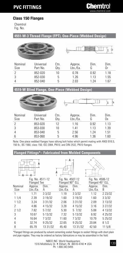
www.chemtrol.com
NIBCO INC. World Headquarters 1516 Middlebury St. • Elkhart, IN 46516-4740 • USA
Ph: 1.800.343.5455139
Class 150 Flanges
pVc Fittings
Chemtrol Fig. No.
Nominal Universal Ctn. Approx. Dim. Dim. Size Part No. Qty. Lbs./Ea. G OF
2 852-020 10 0.78 0.92 1.18 3 852-030 5 1.26 1.13 1.55 4 852-040 5 2.03 1.24 1.67
4551-w-3 thread Flange (Fpt), one-piece (webbed design)
Nominal Universal Ctn. Approx. Dim. Dim. Size Part No. Qty. Lbs./Ea. G OB
2 853-020 12 1.16 0.92 1.13 3 853-030 10 1.41 1.13 1.39 4 853-040 5 2.56 1.24 1.51 6 853-060 5 4.96 1.36 1.60Note: One-piece webbed flanges have oblong bolt holes which permit mating with ANSI B16.5, 150 lb.; BS 1560, class 150; ISO 2084, PN10; and DIN 2532, PN10 flanges.
4519-w blind Flange, one-piece (webbed design)
Flanged Fittings*– Fabricated from Molded components
Fig. No. 4511-12 Fig. No. 4507-12 Fig. No. 4506-12 Flanged Tee Flanged 90° ELL Flanged 45° ELLNominal Approx. Dim. Approx. Dim. Approx. Dim. Size Lbs./Ea. A Lbs./Ea. A Lbs./Ea. B 1 1.71 3 3/32 1.19 3 3/32 1.12 2 23/32 1 1/4 2.39 3 19/32 1.60 3 19/32 1.60 3 3/32 1 1/2 3.24 3 31/32 2.06 3 31/32 2.09 3 13/32 2 4.86 4 15/32 3.28 4 15/32 3.16 3 27/32 2 1/2 7.82 5 7/32 5.30 5 7/32 5.08 4 13/32 3 10.67 5 13/32 7.32 5 13/32 6.92 4 25/32 4 16.64 7 3/32 11.60 7 3/32 10.79 5 25/32 6 32.74 9 25/32 22.65 9 25/32 20.84 8 1/2 8 65.79 13 31/32 45.40 13 31/32 42.50 11 5/8
*Flanged fittings are produced by solvent cementing socket flanges to socket fittings with short plain end pipe nipples. They may be ordered as factory fabrications or may be assembled in the field.

NIBCO INC. World Headquarters 1516 Middlebury St. • Elkhart, IN 46516-4740 • USA
Ph: 1.800.343.5455
www.chemtrol.com
140
Chemtrol Fig. No.
Class 150 Flanges
pVc Fittings
4551-a socket Flange (s), Van stone
Van stone Flange assembly list
Item Description Material 1 Connector Hub PVC 2 Flange Ring PVC Coated Aluminum 3 Flange Ring PVC
1/2"–8" 10"–12"
Nominal Universal Ctn. Approx. Dim. Dim. Dim. Dim. Dim. Size Part No. Qty. Lbs./Ea. A B D0 RF N 1/2 854-005 10 0.19 1.00 .50 3.50 1.48 0.11 3/4 854-007 10 0.24 1.13 .50 3.88 1.75 0.11 1 854-010 24 0.38 1.25 .56 4.25 2.04 0.11 1 1/4 854-012 10 0.40 1.38 .63 4.63 2.50 0.11 1 1/2 854-015 12 0.54 1.50 .69 5.00 2.78 0.11 2 854-020 12 0.92 1.63 .75 6.00 3.41 0.11 2 1/2 854-025 5 1.37 1.94 .94 7.00 4.11 0.16 3 854-030 10 1.75 2.40 1.05 7.50 4.81 0.50 4 854-040 10 2.83 2.76 1.16 8.98 6.19 0.48 6 854-060 5 4.19 3.56 1.29 11.00 7.97 0.53 8 854-080 2 6.47 5.01 1.42 13.50 10.45 0.51 10* 854-100 1 10.20 5.83 1.31 16.00 13.29 0.33 12* 854-120 1 17.53 7.45 1.70 19.00 16.00 0.45*Aluminum ring with PVC coating.
Nominal Part Approx. Size No. Lbs./Ea. 1/2 0.11 3/4 0.12 1 0.13 1 1/4 0.14 1 1/2 0.15 2 Use 0.20 2 1/2 Figure No. 0.25 3 & Nom. Size 0.28 4 0.30 6 0.40 8 0.5010 0.5512 0.60
nR 51 Flange gaskets, for class 150 Flanges
Note: These gaskets are 1/8" thick, full face polychloroprene (CR), 70 durometer.

www.chemtrol.com
NIBCO INC. World Headquarters 1516 Middlebury St. • Elkhart, IN 46516-4740 • USA
Ph: 1.800.343.5455141
Unions
pVc Fittings
Chemtrol Fig. No.
Nominal FKM EPDM Ctn. Approx. Dim. Dim. Dim. Size Part No. Part No. Qty. Lbs./Ea. A L S* 1/4 857-002 897-002 10 0.07 1.70 0.40 0.64 1/2 857-005 897-005 10 0.16 2.00 0.43 0.89 3/4 857-007 897-007 10 0.27 2.44 0.45 1.01 1 857-010 897-010 10 0.40 2.83 0.43 1.14 1 1/4 857-012 897-012 5 0.87 4.08 0.79 1.26 1 1/2 857-015 897-015 10 0.93 4.08 0.80 1.39 2 857-020 897-020 10 1.83 5.26 0.80 1.51 3 857-030 897-030 5 3.76 7.17 0.90 1.90 The 2 1/2" Socket Union is available as a fabrication from the 3" size Bushed down.* Socket Depth
4533 FkM/4533E (EpdM) socket Union (s x s)
4533 FkM/4533E (EpdM) socket Union (s x s)
Nominal FKM EPDM Ctn. Approx. Dim. Dim. Dim. Size Part No. Part No. Qty. Lbs./Ea. A L T* 1/4 858-002 898-002 10 0.11 1.70 1.07 0.31 1/2 858-005 898-005 10 0.16 2.00 1.30 0.43 3/4 858-007 898-007 10 0.28 2.44 1.38 0.45 1 858-010 898-010 10 0.41 2.83 1.51 0.53 1 1/4 858-012 898-012 5 0.90 4.08 2.01 0.55 1 1/2 858-015 898-015 10 0.92 4.08 2.16 0.55 2 858-020 898-020 10 1.82 5.26 2.36 0.57 3 858-030 898-030 5 3.96 7.17 2.88 0.95The 2 1/2" Thread Union is available as a fabrication from the 3" size Bushed down.* Thread Joint Engagement

NIBCO INC. World Headquarters 1516 Middlebury St. • Elkhart, IN 46516-4740 • USA
Ph: 1.800.343.5455
www.chemtrol.com
142
Chemtrol Fig. No.
Unions
pVc Fittings
4533-3 FkM / 4533E-3 (EpdM) Female adapter Union ( s x Fpt)
Nominal FKM EPDM Ctn. Approx. Dim. Dim. Dim. Dim. Size Part No. Part No. Qty. Lbs./Ea. A L S* T†
1/2 859-005 899-005 10 0.16 2.00 0.84 0.89 0.43 3/4 859-007 899-007 10 0.26 2.44 0.82 1.02 0.45 1 859-010 899-010 10 0.38 2.83 0.90 1.14 0.53 1 1/4 859-012 899-012 10 0.89 4.08 1.29 1.27 0.55 1 1/2 859-015 899-015 10 0.91 4.08 1.32 1.39 0.55 2 859-020 899-020 5 1.81 5.26 1.41 1.51 0.57 3 859-030 899-030 5 3.86 7.17 1.93 1.91 0.95The 2 1/2" Socket x Thread Union is available as a fabrication from the 3" size Bushed down.* Socket Depth † Thread Joint Engagement
For questions concerning thermoplastic piping systems, please call or fax: 888.446.4226 (ph), 888.336.4226 (fx).

www.chemtrol.com
NIBCO INC. World Headquarters 1516 Middlebury St. • Elkhart, IN 46516-4740 • USA
Ph: 1.800.343.5455143
Metal Transition Unions
pVc Fittings
Chemtrol Fig. No.
Nominal Universal Ctn. Approx. Dim. Dim. Size Part No. Qty. Lbs./Ea. A T* 1/2 1 0.30 1.02 0.43 3/4 1 0.39 1.02 0.45 1 Use Fig. No. 1 0.47 1.19 0.53 1 1/4 & Nom. Size 1 0.77 1.42 0.55 1 1/2 1 1.64 1.42 0.55 2 1 2.48 1.57 0.57 3 1 4.97 2.25 0.95* Thread Joint Engagement
tcss-3 stainless steel End connector (Fpt)
tcbR-3 brass End connector (Fpt)
Nominal Universal Ctn. Approx. Dim. Dim. Size Part No. Qty. Lbs./Ea. A T* 1/2 1 0.33 1.02 0.43 3/4 1 0.43 1.02 0.45 1 Use Fig. No. 1 0.52 1.19 0.53 1 1/4 & Nom. Size 1 0.85 1.42 0.55 1 1/2 1 1.81 1.42 0.55 2 1 2.74 1.57 0.57 3 1 5.45 2.25 0.95* Thread Joint Engagement

NIBCO INC. World Headquarters 1516 Middlebury St. • Elkhart, IN 46516-4740 • USA
Ph: 1.800.343.5455
www.chemtrol.com
144
Chemtrol Fig. No.
Metal Transition Unions
pVc Fittings
tcbR-4 brass End connector (Mpt)
Nominal Universal Ctn. Approx. Dim. Dim. Size Part No. Qty. Lbs./Ea. A T* 1/2 1 0.28 1.66 0.43 3/4 1 0.37 1.69 0.45 1 Use Fig. No. 1 0.44 2.19 0.53 1 1/4 & Nom. Size 1 0.73 2.38 0.55 1 1/2 1 1.56 2.38 0.55 2 1 2.36 2.63 0.57 3 1 4.97 3.50 0.95* Thread Joint Engagement
Nominal Universal Ctn. Approx. Dim. Dim. Size Part No. Qty. Lbs./Ea. A T* 1/2 1 0.31 1.66 0.43 3/4 1 0.41 1.69 0.45 1 Use Fig. No. 1 0.49 2.19 0.53 1 1/4 & Nom. Size 1 0.81 2.38 0.55 1 1/2 1 1.72 2.38 0.55 2 1 2.60 2.63 0.57 3 1 5.45 3.50 0.95* Thread Joint Engagement
tcss-4 stainless steel End connector (Mpt)
For complete technical information and more, refer to our website at www.chemtrol.com.

www.chemtrol.com
NIBCO INC. World Headquarters 1516 Middlebury St. • Elkhart, IN 46516-4740 • USA
Ph: 1.800.343.5455145
Nominal Universal Ctn. Approx. Dim. Size Part No. Qty. Lbs./Ea. N 1/4 1829-002 5 0.06 0.12 1/2 1829-005 25 0.10 0.24 3/4 1829-007 15 0.14 0.24 1 1829-010 20 0.22 0.24 1 1/4 1829-012 10 0.31 0.24 1 1/2 1829-015 10 0.40 0.24 2 1829-020 10 0.57 0.24 2 1/2 1829-025 55 0.73 0.19 3 1829-030 5 1.12 0.18 4 1829-040 5 1.94 0.18 6 1829-060 4 4.01 0.23 8* 1829-080 2 9.23 0.2210 1829-100 1 14.62 0.3512 1829-120 1 25.26 0.46
Nominal Universal Ctn. Approx. Dim. Size Part No. Qty. Lbs./Ea. N 3/4 x 1/2 1829-101 5 0.13 0.43 1 x 1/2 1829-130 5 0.20 0.66 1 x 3/4 1829-131 5 0.20 0.54 1 1/4 x 3/4 1829-167 5 0.28 0.71 1 1/4 x 1 1829-168 5 0.30 0.59 1 1/2 x 1/2 1829-209 5 0.37 XXX 1 1/2 x 3/4 1829-210 5 0.35 0.75 1 1/2 x 1 1829-211 5 0.36 0.62 1 1/2 x 1 1/4 1829-212 5 0.38 0.50 2 x 1 1829-249 5 0.50 0.73 2 x 1 1/2 1829-251 5 0.54 0.48 3 x 2 1829-338 5 1.08 1.23 4 x 2 1829-420 5 1.73 1.57 4 x 3 1829-422 5 1.98 1.18Other Reducing Couplings are produced by solvent cementing Reducer Bushings into Socket Couplings. They may be ordered as factory fabrications or may be assembled in the field.
Couplings
cpVc Fittings
Chemtrol Fig. No.
5101 socket couplings (s x s)
5101-R Reducing socket coupling (s xs)

NIBCO INC. World Headquarters 1516 Middlebury St. • Elkhart, IN 46516-4740 • USA
Ph: 1.800.343.5455
www.chemtrol.com
146
Chemtrol Fig. No.
Couplings
cpVc Fittings
5101-3-3 thread coupling (Fpt x Fpt)
Nominal Universal Ctn. Approx. Dim. Size Part No. Qty. Lbs./Ea. L 1/4 1830-002 5 0.07 1.40 1/2 1830-005 25 0.08 2.02 3/4 1830-007 25 0.13 2.27 1 1830-010 15 0.21 2.52 1 1/4 1830-012 5 0.31 2.77 1 1/2 1830-015 5 0.46 3.02 2 1830-020 5 0.64 3.27 2 1/2 1830-025 5 0.89 3.75 3 1830-030 5 1.30 3.99 4 1830-040 5 2.31 4.74
5101-3-3-R Reducing thread coupling (Fpt x Fpt)
Nominal Universal Ctn. Approx. Dim. Size Part No. Qty. Lbs./Ea. L 3/4 x 1/2 1830-101 5 0.15 2.33 1 x 1/2 1830-130 5 0.22 2.69 1 x 3/4 1830-131 5 0.23 2.69 1 1/4 x 3/4 1830-167 5 0.32 2.99 1 1/4 x 1 1830-168 5 0.34 2.99 1 1/2 x 3/4 1830-210 5 0.39 3.15 1 1/2 x 1 1830-211 5 0.40 3.15 1 1/2 x 1 1/4 1830-212 5 0.42 3.15 2 x 1 1830-249 5 0.53 3.39 2 x 1 1/2 1830-251 5 0.58 3.39Other Reducing Couplings are produced by solvent cementing Reducer Bushings into Socket Couplings. They may be ordered as factory fabrications or may be assembled in the field.

www.chemtrol.com
NIBCO INC. World Headquarters 1516 Middlebury St. • Elkhart, IN 46516-4740 • USA
Ph: 1.800.343.5455147
Adapters
cpVc Fittings
Chemtrol Fig. No.
5103 Female adapter coupling (s x Fpt)
Nominal Universal Ctn. Approx. Dim. Size Part No. Qty. Lbs./Ea. OM
1/2 1836-005 25 0.04 0.94 3/4 1836-007 25 0.06 0.96 1 1836-010 25 0.10 1.14 1 1/4 1836-012 10 0.14 1.11 1 1/2 1836-015 10 0.19 1.11 2 1836-020 10 0.27 1.19 2 1/2 1836-025 5 0.56 1.88 3 1836-030 5 0.79 1.97 4 1836-040 5 1.56 2.08
5104 Male adapter (s x Mpt)
Nominal Universal Ctn. Approx. Dim. Size Part No. Qty. Lbs./Ea. O 1/4 1835-002 5 0.06 0.76 1/2 1835-005 15 0.10 1.13 3/4 1835-007 10 0.15 1.26 1 1835-010 10 0.23 1.38 1 1/4 1835-012 5 0.34 1.51 1 1/2 1835-015 5 0.43 1.63 2 1835-020 5 0.60 1.76 2 1/2 1835-025 5 0.82 1.97 3 1835-030 5 1.27 2.08 4 1835-040 5 1.13 2.46
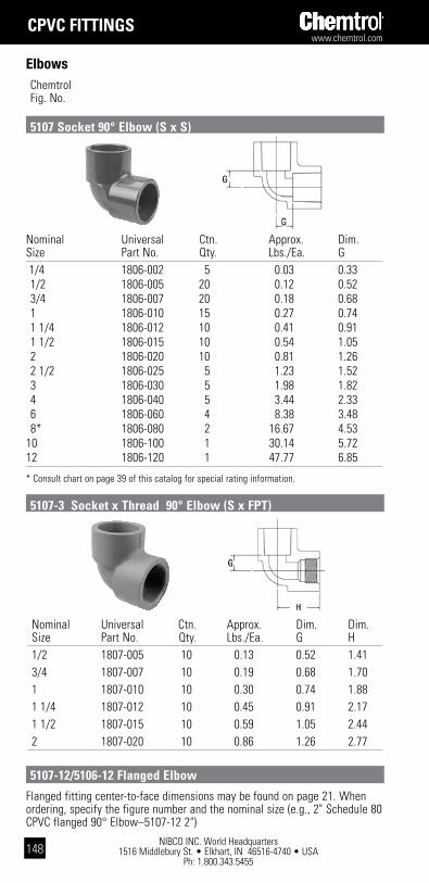
NIBCO INC. World Headquarters 1516 Middlebury St. • Elkhart, IN 46516-4740 • USA
Ph: 1.800.343.5455
www.chemtrol.com
148
Chemtrol Fig. No.
Elbows
cpVc Fittings
Nominal Universal Ctn. Approx. Dim. Dim. Size Part No. Qty. Lbs./Ea. G H 1/2 1807-005 10 0.13 0.52 1.41 3/4 1807-007 10 0.19 0.68 1.70 1 1807-010 10 0.30 0.74 1.88 1 1/4 1807-012 10 0.45 0.91 2.17 1 1/2 1807-015 10 0.59 1.05 2.44 2 1807-020 10 0.86 1.26 2.77
5107-3 socket x thread 90° Elbow (s x Fpt)
Flanged fitting center-to-face dimensions may be found on page 21. When ordering, specify the figure number and the nominal size (e.g., 2" Schedule 80 CPVC flanged 90° Elbow–5107-12 2")
5107-12/5106-12 Flanged Elbow
5107 socket 90° Elbow (s x s)
Nominal Universal Ctn. Approx. Dim.Size Part No. Qty. Lbs./Ea. G 1/4 1806-002 5 0.03 0.33 1/2 1806-005 20 0.12 0.52 3/4 1806-007 20 0.18 0.68 1 1806-010 15 0.27 0.74 1 1/4 1806-012 10 0.41 0.91 1 1/2 1806-015 10 0.54 1.05 2 1806-020 10 0.81 1.26 2 1/2 1806-025 5 1.23 1.52 3 1806-030 5 1.98 1.82 4 1806-040 5 3.44 2.33 6 1806-060 4 8.38 3.48 8* 1806-080 2 16.67 4.5310 1806-100 1 30.14 5.7212 1806-120 1 47.77 6.85
* Consult chart on page 39 of this catalog for special rating information.

www.chemtrol.com
NIBCO INC. World Headquarters 1516 Middlebury St. • Elkhart, IN 46516-4740 • USA
Ph: 1.800.343.5455149
Elbows
cpVc Fittings
Chemtrol Fig. No.
5107-3-3 thread 90° Elbow (Fpt x Fpt)
Nominal Universal Ctn. Approx. Dim. Size Part No. Qty. Lbs./Ea. J 1/4 1817-002 5 0.03 0.18 1/2 1817-005 20 0.10 0.26 3/4 1817-007 10 0.15 0.33 1 1817-010 15 0.24 0.37 1 1/4 1817-012 10 0.34 0.42 1 1/2 1817-015 10 0.47 0.46 2 1817-020 10 0.67 0.60 2 1/2 1817-025 5 0.99 0.67 3 1817-030 6 1.48 0.77 4 1817-040 6 2.62 1.01 6 1817-060 4 6.62 1.74 8* 1817-080 2 13.63 2.2010 1817-100 1 21.44 2.5912 1817-120 1 35.59 3.05*Consult chart on page 39 of this catalog for special rating information.
5106 socket 45° Elbow (s x s)
Nominal Universal Ctn. Approx. Dim. Size Part No. Qty. Lbs./Ea. H 1/4 1808-002 5 0.03 0.97 1/2 1808-005 10 0.13 1.41 3/4 1808-007 25 0.19 1.70 1 1808-010 15 0.30 1.88 1 1/4 1808-012 5 0.45 2.17 1 1/2 1808-015 5 0.59 2.44 2 1808-020 5 0.86 2.77 2 1/2 1808-025 5 1.34 3.30 3 1808-030 5 2.14 3.73 4 1808-040 5 3.85 4.61

NIBCO INC. World Headquarters 1516 Middlebury St. • Elkhart, IN 46516-4740 • USA
Ph: 1.800.343.5455
www.chemtrol.com
150
Chemtrol Fig. No.
Elbows
cpVc Fittings
5106-3-3 thread 45° Elbow (Fpt x Fpt)
Nominal Universal Ctn. Approx. Dim. Size Part No. Qty. Lbs./Ea. K 1/4 1819-002 5 0.04 0.82 1/2 1819-005 10 0.11 1.15 3/4 1819-007 10 0.16 1.34 1 1819-010 15 0.27 1.51 1 1/4 1819-012 5 0.38 1.69 1 1/2 1819-015 5 0.52 1.85 2 1819-020 5 0.76 2.12 2 1/2 1819-025 5 1.09 2.45 3 1819-030 6 1.70 2.68 4 1819-040 6 3.06 3.29
Nominal Universal Ctn. Approx. Dim. Dim. Dim. Size Part No. Qty. Lbs./Ea. G G I 1/4 1801-002 5 0.05 0.33 0.33 0.33 1/2 1801-005 25 0.16 0.52 0.52 0.52 3/4 1801-007 15 0.26 0.68 0.68 0.68 1 1801-010 20 0.39 0.74 0.74 0.74 1 1/4 1801-012 10 0.58 0.91 0.91 0.91 1 1/2 1801-015 10 0.78 1.05 1.05 1.05 2 1801-020 10 1.13 1.26 1.26 1.26 2 1/2 1801-025 5 1.72 1.52 1.52 1.52 3 1801-030 5 2.51 1.82 1.82 1.82 4 1801-040 5 4.41 2.33 2.33 2.33 6 1801-060 4 11.11 3.48 3.48 3.48 8* 1801-080 1 22.28 4.53 4.53 4.5310 1801-100 1 38.52 5.72 5.72 5.7212 1801-120 1 63.55 6.85 6.85 6.85* Consult chart on page 41 of this catalog for special rating information.
5111 socket tee (s x s x s)
Chemtrol Fig. No.
Tees

www.chemtrol.com
NIBCO INC. World Headquarters 1516 Middlebury St. • Elkhart, IN 46516-4740 • USA
Ph: 1.800.343.5455151
Tees
cpVc Fittings
Chemtrol Fig. No.
5111-12 Flanged tees
Nominal Universal Ctn. Approx. Dim. Dim. Dim. Size Part No. Qty. Lbs./Ea. G G I 3/4 x 3/4 x 1/2 1801-101 10 0.19 0.51 0.51 0.62 1 x 1 x 1/2 1801-130 10 0.26 0.52 0.52 0.73 1 x 1 x 3/4 1801-131 10 0.28 0.62 0.62 0.73 1 1/2 x 1 1/2 x 3/4 1801-210 10 0.51 0.66 0.66 1.04 1 1/2 x 1 1/2 x 1 1801-211 10 0.56 0.76 0.76 1.03 2 x 2 x 1/2 1801-247 5 0.65 0.60 0.60 1.29 2 x 2 x 3/4 1801-248 5 0.70 0.70 0.70 1.29 2 x 2 x 1 1801-249 5 0.75 0.80 0.80 1.29 2 x 2 x 1 1/2 1801-251 5 0.89 1.07 1.07 1.29 3 x 3 x 2 1801-338 5 1.92 1.36 1.36 1.84 4 x 4 x 2 1801-420 5 3.02 1.39 1.39 2.34 4 x 4 x 3 1801-422 5 3.62 1.87 1.87 2.34 6 x 6 x 4 1801-532 4 7.69 2.56 2.56 3.52Other Reducing Tees are produced by solvent cementing Reducer Bushings with Socket Tees. They may be ordered as factory fabrications or may be assembled in the field.
Flanged fitting center-to-face dimensions may be found on page 21. Whenordering, specify the figure number and the nominal size (e.g., 2" Schedule 80CPVC flanged tee–5111-12 2")
5111R Reducing socket tee (s x s x s)
5112 socket x thread tee (s x s x Fpt)
Nominal Universal Ctn. Approx. Dim. Dim. Dim. Size Part No. Qty. Lbs./Ea. G G H 1/2 1802-005 10 0.17 0.52 0.52 1.41 3/4 1802-007 10 0.28 0.68 0.68 1.70 1 1802-010 10 0.43 0.74 0.74 1.88 1 1/4 1802-012 10 0.62 0.91 0.91 2.17 1 1/2 1802-015 10 0.88 1.05 1.05 2.44 2 1802-020 10 1.23 1.26 1.26 2.77
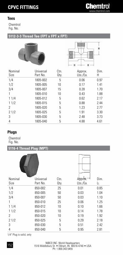
NIBCO INC. World Headquarters 1516 Middlebury St. • Elkhart, IN 46516-4740 • USA
Ph: 1.800.343.5455
www.chemtrol.com
152
Chemtrol Fig. No.
Tees
cpVc Fittings
5112-3-3 thread tee (Fpt x Fpt x Fpt)
Nominal Universal Ctn. Approx. Dim. Size Part No. Qty. Lbs./Ea. H 1/4 1805-002 5 0.06 0.97 1/2 1805-005 10 0.17 1.41 3/4 1805-007 15 0.28 1.70 1 1805-010 10 0.43 1.88 1 1/4 1805-012 5 0.62 2.17 1 1/2 1805-015 5 0.88 2.44 2 1805-020 5 1.23 2.77 2 1/2 1805-025 5 1.91 3.30 3 1805-030 5 2.48 3.73 4 1805-040 5 4.88 4.61
Nominal Universal Ctn. Approx. Dim. Size Part No. Qty. Lbs./Ea. LL
1/4 850-002 25 0.01 0.85 1/2 850-005 50 0.03 1.04 3/4 850-007 50 0.03 1.10 1 850-010 25 0.06 1.25 1 1/4 850-012 10 0.10 1.66 1 1/2 850-015 10 0.14 1.78 2 850-020 10 0.19 1.92 2 1/2 850-025 5 0.29 2.18 3 850-030 5 0.51 2.42 4 850-040 5 0.95 2.811/4" Plug is solid, only
Chemtrol Fig. No.
Plugs
5116-4 thread plug (Mpt)
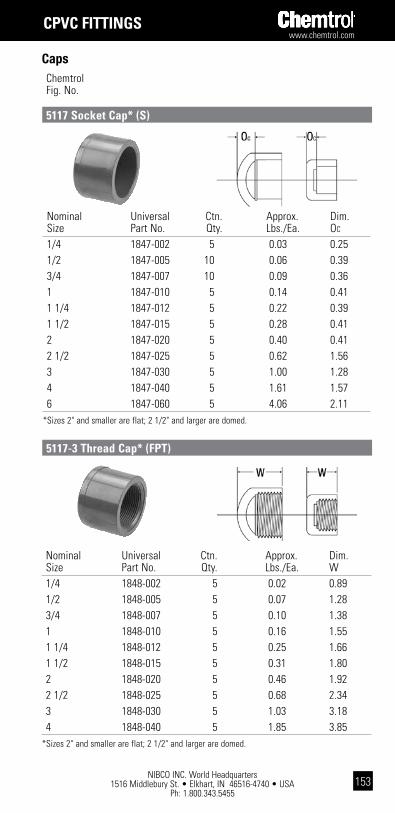
www.chemtrol.com
NIBCO INC. World Headquarters 1516 Middlebury St. • Elkhart, IN 46516-4740 • USA
Ph: 1.800.343.5455153
Nominal Universal Ctn. Approx. Dim. Size Part No. Qty. Lbs./Ea. W 1/4 1848-002 5 0.02 0.89 1/2 1848-005 5 0.07 1.28 3/4 1848-007 5 0.10 1.38 1 1848-010 5 0.16 1.55 1 1/4 1848-012 5 0.25 1.66 1 1/2 1848-015 5 0.31 1.80 2 1848-020 5 0.46 1.92 2 1/2 1848-025 5 0.68 2.34 3 1848-030 5 1.03 3.18 4 1848-040 5 1.85 3.85*Sizes 2" and smaller are flat; 2 1/2" and larger are domed.
Caps
cpVc Fittings
Chemtrol Fig. No.
5117 socket cap* (s)
5117-3 thread cap* (Fpt)
Nominal Universal Ctn. Approx. Dim. Size Part No. Qty. Lbs./Ea. OC
1/4 1847-002 5 0.03 0.25 1/2 1847-005 10 0.06 0.39 3/4 1847-007 10 0.09 0.36 1 1847-010 5 0.14 0.41 1 1/4 1847-012 5 0.22 0.39 1 1/2 1847-015 5 0.28 0.41 2 1847-020 5 0.40 0.41 2 1/2 1847-025 5 0.62 1.56 3 1847-030 5 1.00 1.28 4 1847-040 5 1.61 1.57 6 1847-060 5 4.06 2.11*Sizes 2" and smaller are flat; 2 1/2" and larger are domed.

NIBCO INC. World Headquarters 1516 Middlebury St. • Elkhart, IN 46516-4740 • USA
Ph: 1.800.343.5455
www.chemtrol.com
154
cpVc Fittings
Bushings
The design style of most bushings is to have a solid wall between the inside and outside connections. Some of the multistep reductions with exceedingly thick cross-sections are not solid. This design style achieves structural support with a web of ribs attaching the inner and outer connection walls, with the open area toward the exterior bushing face. The styles are denoted by W and S for webbed and solid designs respectively.
Webbed design Solid design
design styles
Nominal Universal Ctn. Approx. Design Dim. Dim. Size Part No. Qty. Lbs./Ea. Style LL NN
1/2 x 1/4 1837-072 25 0.04 S 1.17 0.53 3/4 x 1/2 1837-101 25 0.06 S 1.15 0.26 1 x 1/2 1837-130 25 0.07 S 1.28 0.39 1 x 3/4 1837-131 25 0.06 S 1.28 0.26 1 1/4 x 1/2 1837-166 10 0.11 S 1.41 0.52 1 1/4 x 3/4 1837-167 10 0.09 S 1.41 0.39 1 1/4 x 1 1837-168 10 0.07 S 1.41 0.27 1 1/2 x 1/2 1837-209 10 0.13 W 1.53 0.64 1 1/2 x 3/4 1837-210 10 0.11 S 1.53 0.51 1 1/2 x 1 1837-211 10 0.09 S 1.53 0.39 1 1/2 x 1 1/4 1837-212 10 0.07 S 1.53 0.26 2 x 1/2 1837-247 10 0.27 W 1.66 0.77 2 x 3/4 1837-248 10 0.27 W 1.66 0.64 2 x 1 1837-249 10 0.27 W 1.66 0.52 2 x 1 1/4 1837-250 5 0.23 S 1.66 0.39 2 x 1 1/2 1837-251 10 0.21 S 1.66 0.27 2 1/2 x 1 1837-289 5 0.46 W 1.94 0.80 2 1/2 x 1 1/2 1837-291 5 0.39 S 1.94 0.55 2 1/2 x 2 1837-292 5 0.26 S 1.93 0.42 3 x 1 1/2 1837-337 5 0.75 W 2.41 1.02 3 x 2 1837-338 5 0.70 S 2.41 0.90 3 x 2 1/2 1837-339 5 0.49 S 2.41 0.63
Chemtrol Fig. No.
5118 Flush socket Reducer bushing (spg x s)

www.chemtrol.com
NIBCO INC. World Headquarters 1516 Middlebury St. • Elkhart, IN 46516-4740 • USA
Ph: 1.800.343.5455155
Nominal Universal Ctn. Approx. Design Dim. Dim. Size Part No. Qty. Lbs./Ea. Style LL Y* 1/2 x 1/4 1838-072 25 0.03 S 1.17 0.31 3/4 x 1/2 1838-101 25 0.03 S 1.29 0.43 1 x 1/2 1838-130 25 0.07 S 1.56 0.43 1 x 3/4 1838-131 25 0.06 S 1.56 0.45 1 1/4 x 1/2 1838-166 10 0.15 S 1.66 0.43 1 1/4 x 3/4 1838-167 10 0.13 S 1.66 0.45 1 1/4 x 1 1838-168 10 0.11 S 1.66 0.53 1 1/2 x 1/2 1838-209 10 0.23 S 1.77 0.43 1 1/2 x 3/4 1838-210 10 0.21 S 1.77 0.45 1 1/2 x 1 1838-211 10 0.19 S 1.77 0.53 1 1/2 x 1 1/4 1838-212 10 0.13 S 1.77 0.55 2 x 1/2 1838-247 10 0.36 S 1.91 0.43 2 x 3/4 1838-248 10 0.34 S 1.91 0.45 2 x 1 1838-249 10 0.32 S 1.91 0.53 2 x 1 1/4 1838-250 10 0.26 S 1.91 0.55 2 x 1 1/2 1838-251 10 0.21 S 1.91 0.55 2 1/2 x 2 1838-292 5 0.32 S 2.17 0.57 3 x 2 1838-338 5 0.73 S 2.41 0.57 3 x 2 1/2 1838-339 5 0.57 S 2.41 0.87 4 x 2 1838-420 5 1.30 W 2.80 0.57 4 x 3 1838-422 5 1.06 S 2.80 0.95Other size reductions are produced by solvent cementing appropriate Reducer Bushings together. They may be ordered as factory fabrications or may be assembled in the field.*Typical male component engagement, hand tight (L1 in ANSI B1.20.1 thread spec.) plus 1 1/2 turns.
Caps
cpVc Fittings
Chemtrol Fig. No.
5118 Flush socket Reducer bushing (spg x s) (cont.)
5118-3 Flush spigot x thread Reducer bushing (spg x Fpt)
Nominal Universal Ctn. Approx. Design Dim. Dim. Size Part No. Qty. Lbs./Ea. Style LL NN
4 x 2 1837-420 5 1.25 W 2.80 1.29 4 x 3 1837-422 5 1.01 S 2.80 0.90 6 x 4 1837-532 5 2.97 S 3.05 0.77 8 x 6 1837-585 2 6.00 S 4.58 1.5510 x 6 1837-422 1 10.80 W 5.57 2.5410 x 8 1837-626 1 9.36 S 5.57 1.0712 x 8 1837-668 1 18.79 W 6.57 2.0712 x 10 1837-670 1 12.78 S 6.57 1.07
Other size reductions are produced by solvent cementing appropriate Reducer Bushings together. They may be ordered as factory fabrications or may be assembled in the field.

NIBCO INC. World Headquarters 1516 Middlebury St. • Elkhart, IN 46516-4740 • USA
Ph: 1.800.343.5455
www.chemtrol.com
156
Chemtrol Fig. No.
Tees
cpVc Fittings
5118-3-4 Flush thread Reducer bushing (Mpt x Fpt)
YLL
Nominal Universal Ctn. Approx. Design Dim. Dim. Size Part No. Qty. Lbs./Ea. Style LL Y* 1/2 x 1/4 1839-072 25 0.02 S 0.95 0.25 3/4 x 1/2 1839-101 25 0.03 S 0.95 0.25 1 x 1/2 1839-130 25 0.06 S 1.24 0.38 1 x 3/4 1839-131 25 0.05 S 1.24 0.38 1 1/4 x 1/2 1839-166 10 0.13 S 1.27 0.38 1 1/4 x 3/4 1839-167 10 0.11 S 1.27 0.38 1 1/4 x 1 1839-168 10 0.09 S 1.27 0.38 1 1/2 x 1/2 1839-209 10 0.20 S 1.28 0.38 1 1/2 x 3/4 1839-210 10 0.18 S 1.28 0.38 1 1/2 x 1 1839-211 10 0.17 S 1.28 0.38 1 1/2 x 1 1/4 1839-212 10 0.11 S 1.28 0.38 2 x 1/2 1839-247 5 0.30 S 1.32 0.38 2 x 3/4 1839-248 5 0.28 S 1.32 0.38 2 x 1 1839-249 5 0.28 S 1.32 0.38 2 x 1 1/4 1839-250 5 0.27 S 1.32 0.38 2 x 1 1/2 1839-251 5 0.15 S 1.32 0.38 2 1/2 x 2 1839-292 5 0.24 S 2.18 0.57 3 x 1 1/2 1839-337 5 0.64 W 2.42 0.55 3 x 2 1839-338 5 0.59 S 2.42 0.57 3 x 2 1/2 1839-339 5 0.54 S 2.42 0.87 4 x 2 1839-420 5 1.01 W 2.81 0.57 4 x 3 1839-422 5 0.95 S 2.81 0.95Other size reductions are produced by solvent cementing appropriate Reducer Bushings together. They may be ordered as factory fabrications or may be assembled in the field.*Typical male component engagement, hand tight (L1 in ANSI B1.20.1 thread spec.) plus 1 1/2 turns.
Chemtrol has seminars available to educate in the design and installation of thermoplastic piping systems. For more information, call our customer service department at 800.343.5455.
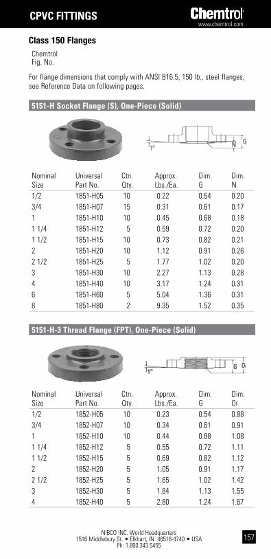
www.chemtrol.com
NIBCO INC. World Headquarters 1516 Middlebury St. • Elkhart, IN 46516-4740 • USA
Ph: 1.800.343.5455157
For flange dimensions that comply with ANSI B16.5, 150 lb., steel flanges, see Reference Data on following pages.
Nominal Universal Ctn. Approx. Dim. Dim. Size Part No. Qty. Lbs./Ea. G N 1/2 1851-H05 10 0.22 0.54 0.20 3/4 1851-H07 15 0.31 0.61 0.17 1 1851-H10 10 0.45 0.68 0.18 1 1/4 1851-H12 5 0.59 0.72 0.20 1 1/2 1851-H15 10 0.73 0.82 0.21 2 1851-H20 10 1.12 0.91 0.26 2 1/2 1851-H25 5 1.77 1.02 0.20 3 1851-H30 10 2.27 1.13 0.28 4 1851-H40 10 3.17 1.24 0.31 6 1851-H60 5 5.04 1.36 0.31 8 1851-H80 2 9.35 1.52 0.35
Nominal Universal Ctn. Approx. Dim. Dim. Size Part No. Qty. Lbs./Ea. G OF
1/2 1852-H05 10 0.23 0.54 0.88 3/4 1852-H07 10 0.34 0.61 0.91 1 1852-H10 10 0.44 0.68 1.08 1 1/4 1852-H12 5 0.55 0.72 1.11 1 1/2 1852-H15 5 0.69 0.82 1.12 2 1852-H20 5 1.05 0.91 1.17 2 1/2 1852-H25 5 1.65 1.02 1.42 3 1852-H30 5 1.84 1.13 1.55 4 1852-H40 5 2.80 1.24 1.67
Class 150 Flanges
cpVc Fittings
Chemtrol Fig. No.
5151-h socket Flange (s), one-piece (solid)
5151-h-3 thread Flange (Fpt), one-piece (solid)

NIBCO INC. World Headquarters 1516 Middlebury St. • Elkhart, IN 46516-4740 • USA
Ph: 1.800.343.5455
www.chemtrol.com
158
Chemtrol Fig. No.
Class 150 Flanges
cpVc Fittings
5119-h blind Flange, one-piece (solid)
Nominal Universal Ctn. Approx. Dim. Dim. Size Part No. Qty. Lbs./Ea. G N 2 1851-020 10 0.89 0.91 0.26 3 1851-030 10 1.80 1.13 0.28 4 1851-040 10 2.72 1.24 0.31 6 1851-060 5 4.14 1.36 0.31Note: One-piece webbed flanges have oblong bolt holes which permit mating with ANSI B16.5, 150 lb.; BS 1560, class 150; ISO 2084, PN10; and DIN 2532, PN10.
Nominal Universal Ctn. Approx. Dim. Dim. Size Part No. Qty. Lbs./Ea. G OF
2 1852-020 5 0.88 0.91 1.17 3 1852-030 5 1.73 1.13 1.55 4 1852-040 5 2.53 1.24 1.67
Nominal Universal Ctn. Approx. Dim. Dim. Size Part No. Qty. Lbs./Ea. G OB
1/2 1853-H05 5 0.28 0.54 0.76 3/4 1853-H07 5 0.34 0.61 0.83 1 1853-H10 5 0.48 0.68 0.88 1 1/4 1853-H12 5 0.63 0.72 0.95 1 1/2 1853-H15 5 0.81 0.82 1.04 2 1853-H20 5 1.24 0.91 1.12 2 1/2 1853-H25 5 2.03 1.02 1.22 3 1853-H30 5 2.65 1.13 1.39 4 1853-H40 5 3.94 1.24 1.57 6 1853-H60 5 6.93 1.36 1.60 8 1853-H80 2 11.23 1.51 1.77
5151-w socket Flange (s), one-piece (webbed design)
5151-w-3 thread Flange (Fpt), one-piece (webbed design)

www.chemtrol.com
NIBCO INC. World Headquarters 1516 Middlebury St. • Elkhart, IN 46516-4740 • USA
Ph: 1.800.343.5455159
Item Description Material 1 Connector Hub CPVC 3 Flange Ring CPVC
5119-w blind Flange, one-piece (webbed design) Nominal Universal Ctn. Approx. Dim. Dim. Size Part No. Qty. Lbs./Ea. G OB
2 1853-020 5 0.88 0.91 1.17 3 1853-030 5 1.98 1.13 1.39 4 1853-040 5 2.88 1.24 1.51 6 1853-060 5 5.07 1.36 1.60Note: One-piece webbed flanges have oblong bolt holes which permit mating with ANSI B16.5, 150 lb.; BS 1560, class 150; ISO 2084, PN10; and DIN 2532, PN10.
Nominal Universal Ctn. Approx. Dim. Dim. Dim. Dim. Dim. Size Part No. Qty. Lbs./Ea. A B D0 RF N 1/2 1854-005 10 0.21 1.00 .50 3.49 1.48 0.11 3/4 1854-007 15 0.26 1.12 .50 3.86 1.75 0.11 1 1854-010 10 0.41 1.25 .56 4.24 2.04 0.11 1 1/4 1854-012 5 0.44 1.37 .63 4.61 2.50 0.11 1 1/2 1854-015 10 0.59 1.50 .69 4.99 2.78 0.11 2 1854-020 10 1.00 1.62 .75 5.98 3.41 0.11 2 1/2 1854-025 5 1.49 1.93 .94 6.98 4.11 0.15 3 1854-030 10 1.87 2.40 1.04 7.48 4.80 0.50 4 1854-040 10 2.84 2.75 1.16 8.95 6.17 0.48 6 1854-060 5 4.88 3.55 1.28 10.97 7.95 0.53 8 1854-080 2 13.13 5.00 1.42 13.46 10.42 0.50
Class 150 Flanges
cpVc Fittings
Chemtrol Fig. No.
5119-w blind Flange, one-piece (webbed design)
5151-a socket Flange (s), Van stone
Van stone Flange assembly list

NIBCO INC. World Headquarters 1516 Middlebury St. • Elkhart, IN 46516-4740 • USA
Ph: 1.800.343.5455
www.chemtrol.com
160
Flanged Tee Flanged 90° ELL Flanged 45° ELL Nominal Approx. Dim. Approx. Dim. Approx. Dim. Size Lbs./Ea. A Lbs./Ea. A Lbs./Ea. B 1 1.98 3 3/32 1.34 3 3/32 1.31 2 23/32 1 1/4 2.75 3 19/32 1.86 3 19/32 1.79 3 3/32 1 1/2 3.49 3 31/32 2.35 3 31/32 2.27 3 13/32 2 5.23 4 15/32 3.54 4 15/32 3.40 3 27/32 2 1/2 8.38 5 7/32 5.67 5 7/32 5.43 4 13/32 3 11.32 5 13/32 7.85 5 13/32 7.35 4 25/32 4 17.36 7 3/32 12.07 7 3/32 11.29 5 25/32 6 32.74 9 25/32 24.50 9 25/32 22.75 8 1/2 8 – – – – – – * Flanged fittings are produced by solvent cementing socket flanges to socket fittings with
short plain end pipe nipples.
Chemtrol Fig. No.
Class 150 Flanges
cpVc Fittings
Flanged Fittings*– Fabricated from Molded components
Unions Chemtrol Fig. No.
5133 FkM/5133E (EpdM) socket Union (s x s)
Nominal FKM EPDM Ctn. Approx. Dim. Dim. Dim. Size Part No. Part No. Qty. Lbs./Ea. A L S* 1/4 1857-002 1897-002 5 0.10 1.70 0.41 0.64 1/2 1857-005 1897-005 10 0.17 1.99 0.43 0.89 3/4 1857-007 1897-007 10 0.30 2.43 0.44 1.02 1 1857-010 1897-010 5 0.43 2.82 0.43 1.14 1 1/4 1857-012 1897-012 5 0.94 4.07 0.79 1.27 1 1/2 1857-015 1897-015 5 1.01 4.07 0.81 1.39 2 1857-020 1897-020 5 1.98 5.24 0.80 1.52 3 1857-030 1897-030 5 3.77 7.15 0.94 1.91 The 2 1/2" Socket Union is available as a fabrication from the 3" size Bushed down.
* Socket Depth
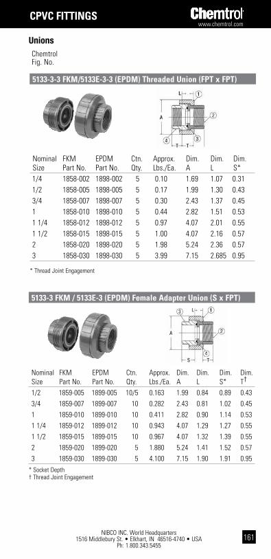
www.chemtrol.com
NIBCO INC. World Headquarters 1516 Middlebury St. • Elkhart, IN 46516-4740 • USA
Ph: 1.800.343.5455161
Unions
cpVc Fittings
Chemtrol Fig. No.
Nominal FKM EPDM Ctn. Approx. Dim. Dim. Dim. Size Part No. Part No. Qty. Lbs./Ea. A L S* 1/4 1858-002 1898-002 5 0.10 1.69 1.07 0.31 1/2 1858-005 1898-005 5 0.17 1.99 1.30 0.43 3/4 1858-007 1898-007 5 0.30 2.43 1.37 0.45 1 1858-010 1898-010 5 0.44 2.82 1.51 0.53 1 1/4 1858-012 1898-012 5 0.97 4.07 2.01 0.55 1 1/2 1858-015 1898-015 5 1.00 4.07 2.16 0.57 2 1858-020 1898-020 5 1.98 5.24 2.36 0.57 3 1858-030 1898-030 5 3.99 7.15 2.685 0.95
* Thread Joint Engagement
5133-3-3 FkM/5133E-3-3 (EpdM) threaded Union (Fpt x Fpt)
5133-3 FkM / 5133E-3 (EpdM) Female adapter Union (s x Fpt)
Nominal FKM EPDM Ctn. Approx. Dim. Dim. Dim. Dim. Size Part No. Part No. Qty. Lbs./Ea. A L S* T†
1/2 1859-005 1899-005 10/5 0.163 1.99 0.84 0.89 0.43 3/4 1859-007 1899-007 10 0.282 2.43 0.81 1.02 0.45 1 1859-010 1899-010 10 0.411 2.82 0.90 1.14 0.53 1 1/4 1859-012 1899-012 10 0.943 4.07 1.29 1.27 0.55 1 1/2 1859-015 1899-015 10 0.967 4.07 1.32 1.39 0.55 2 1859-020 1899-020 5 1.880 5.24 1.41 1.52 0.57 3 1859-030 1899-030 5 4.100 7.15 1.90 1.91 0.95* Socket Depth † Thread Joint Engagement

NIBCO INC. World Headquarters 1516 Middlebury St. • Elkhart, IN 46516-4740 • USA
Ph: 1.800.343.5455
www.chemtrol.com
162
The bench-mount socket fusion machine is designed to join polypropylene and Kynar® PVDF IPS piping systems. Each machine, Models 7511XT, 3511, and 3600, is sized and specified to handle a particular range of IPS pipe sizes. Two clamps hold the pipe and one clamp holds the correspond-ing fitting or valve end connector in the precise position for socket fusion. Detailed operating instructions are found in the Chemtrol Thermoplastic Piping Technical Manual.
The basic machine comes in a steel or wood shipping crate with the heat-ing tool, wrench, fixtures, clamping unit, and joining instructions. the socket heat Face sets are ordered separately.
1/2” - 6” benchmount Fusion tools
model no.
size range
size (w x d x h) handle down
weight (lbs.) volts phase watts
w/case
7511XT *1/2" – 2" 23 x 18 x 12.5 95.5 110(+/- 10%) Single 630
3511 1/2" – 4" 32 x 24 x 19 181.5 110(+/- 10%) Single 1200
3600 4" – 6" 42 x 28 x 19 302 220(+/- 10%) Single 1200
*7511XT machine does not fit 1-1/2" and 2" flanges.
sockEt FUsion EqUipMEnt
Bench-Mount Fusion Machines
Kynar® is a registered trademark of Arkema Inc.

www.chemtrol.com
NIBCO INC. World Headquarters 1516 Middlebury St. • Elkhart, IN 46516-4740 • USA
Ph: 1.800.343.5455163
Each kit contains all of the components required for joining all sizes of socket fusion connections specified for that kit, including: heating tool, male and female heat face sets with bolts, depth gages, cold ring pipe clamp with inserts, pipe cutter, beveling tool, timer, thermal blanket, auxil-iary handle, hex key wrenches, thermostat adjustment tool, joining instruc-tions and rugged heavy duty tool box.
Multiple size Joining kits 1/2" - 2" or 3" - 4"
model no. size range volts phase watts
C168860 1/2”- 2” 110 (+/- 10%) Single 800
C169060 3”- 4” 110 (+/- 10%) Single 1650
sockEt FUsion EqUipMEnt
Hand Held Fusion Tool - Multi-Size Joining Kits

NIBCO INC. World Headquarters 1516 Middlebury St. • Elkhart, IN 46516-4740 • USA
Ph: 1.800.343.5455
www.chemtrol.com
164
Pipe
polYpRopYlEnE Fittings
Chemtrol Fig. No.
6100-80(1/2”-6”)/6200-80(1/2”-4”) plain End schedule 80 pipe (20 ft. lengths)
Pipe is ordered and specified with the Chemtrol figure number followed by the nom-inal size (e.g., 1 1/2" Schedule 80 PP Pipe – 6100 1 1/2"). Weights and dimensions for all pipe may be found in the Reference Data section of this catalog.
Couplings Chemtrol Fig. No.
6101/6201 socket couplings (s x s)
Nominal Universal Part No. Ctn. Approx. Dim.
Size Black Chem-Pure Qty. Lbs./Ea. N 1/2 2829-005 7829-005 10 0.06 0.29 3/4 2829-007 7829-007 10 0.08 0.29 1 2829-010 7829-010 10 0.13 0.28 1 1/2 2829-015 7829-015 10 0.22 0.28 2 2829-020 7829-020 10 0.35 0.27 3 2829-030 7829-030 5 0.60 0.24 4 2829-040 7829-040 5 1.01 0.22 6 2829-060 — 2 2.37 0.26

www.chemtrol.com
NIBCO INC. World Headquarters 1516 Middlebury St. • Elkhart, IN 46516-4740 • USA
Ph: 1.800.343.5455165
Chemtrol Fig. No.
Couplings
polYpRopYlEnE Fittings
6101-3-3/6201-3-3 thread* coupling (Fpt x Fpt)
Nominal Universal Part No. Ctn. Approx. Dim. Size Black Chem-Pure Qty. Lbs./Ea. L 1/2 2830-005 7830-005 10 0.06 1.99 3/4 2830-007 7830-007 10 0.09 2.24 1 2830-010 7830-010 10 0.14 2.48 1 1/4 2830-012 7830-012 10 0.19 2.73 1 1/2 2830-015 7830-015 10 0.26 2.98 2 2830-020 7830-020 10 0.35 3.22 3 2830-030 7830-030 5 0.73 3.93 4 2830-040 7830-040 5 1.21 4.66*Recommended for intermittent service not exceeding 20 psi.
6103/6203 Female adapter coupling (s x Fpt*)
Chemtrol Fig. No.
Adapters
Nominal Universal Part No. Ctn. Approx. Dim. Size Black Chem-Pure Qty. Lbs./Ea. O 1/2 2835-005 7835-005 10 0.06 1.14 3/4 2835-007 7835-007 10 0.08 1.26 1 2835-010 7835-010 10 0.13 1.38 1 1/2 2835-015 7835-015 10 0.24 1.63 2 2835-020 7835-020 10 0.34 1.75 3 2835-030 7835-030 5 0.65 2.08 4 2835-040 7835-040 5 1.16 2.44*Recommended for intermittent service not exceeding 20 psi.
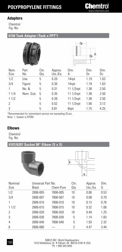
NIBCO INC. World Headquarters 1516 Middlebury St. • Elkhart, IN 46516-4740 • USA
Ph: 1.800.343.5455
www.chemtrol.com
166
Nom. Part Ctn. Approx. Dim. Dim. Dim. Size No. Qty. Lbs./Ea. A OR DO
1/2 Use 5 0.20 14npt 1.19 1.63 3/4 Figure 5 0.30 14npt 1.19 1.63 1 No. & 5 0.31 11 1/2npt 1.38 2.50 1 1/4 Nom. Size 5 0.35 11 1/2npt 1.38 2.50 1 1/2 5 0.39 11 1/2npt 1.38 2.50 2 5 0.52 11 1/2npt 1.56 3.13 3 5 0.81 8npt 1.75 4.25*Recommended for intermittent service not exceeding 20 psi. Note: 1. Gasket is EPDM
Adapters
polYpRopYlEnE Fittings
Chemtrol Fig. No.
6150 tank adapter (tank x Fpt*)
Elbows Chemtrol Fig. No.
6107/6207 socket 90° Elbow (s x s)
Nominal Universal Part No. Ctn. Approx. Dim. Size Black Chem-Pure Qty. Lbs./Ea. G 1/2 2806-005 7806-005 10 0.06 0.53 3/4 2806-007 7806-007 10 0.08 0.70 1 2806-010 7806-010 10 0.15 0.76 1 1/2 2806-015 7806-015 10 0.32 1.06 2 2806-020 7806-020 10 0.49 1.25 3 2806-030 7806-030 5 1.14 1.83 4 2806-040 7806-040 5 1.93 2.32 6 2806-060 — 2 4.47 3.44

www.chemtrol.com
NIBCO INC. World Headquarters 1516 Middlebury St. • Elkhart, IN 46516-4740 • USA
Ph: 1.800.343.5455167
Chemtrol Fig. No.
Elbows
polYpRopYlEnE Fittings
6107-3-3/6207-3-3 thread* 90°Elbow(Fpt x Fpt)
Nominal Universal Part No. Ctn. Approx. Dim. Size Black Chem-Pure Qty. Lbs./Ea. H 1/2 2808-005 7808-005 10 0.07 1.38 3/4 2808-007 7808-007 10 0.11 1.67 1 2808-010 7808-010 10 0.16 1.86 1 1/4 2808-012 7808-012 10 0.25 2.14 1 1/2 2808-015 7808-015 10 0.33 2.41 2 2808-020 7808-020 10 0.49 2.73 3 2808-030 7808-030 5 1.12 3.67 4 2808-040 7808-040 5 2.02 4.54*Recommended for intermittent service not exceeding 20 psi.
6106/6206 socket 45° Elbow (s x s)
Nominal Universal Part No. Ctn. Approx. Dim. Size Black Chem-Pure Qty. Lbs./Ea. J 1/2 2817-005 7817-005 10 0.06 0.28 3/4 2817-007 7817-007 10 0.08 0.35 1 2817-010 7817-010 10 0.14 0.38 1 1/2 2817-015 7817-015 10 0.25 0.48 2 2817-020 7817-020 10 0.37 0.61 3 2817-030 7817-030 5 0.80 0.79 4 2817-040 7817-040 5 1.54 1.02 6 2817-060 — 2 3.55 1.72

NIBCO INC. World Headquarters 1516 Middlebury St. • Elkhart, IN 46516-4740 • USA
Ph: 1.800.343.5455
www.chemtrol.com
168
Nominal Universal Part No. Ctn. Approx. Dim. Size Black Chem-Pure Qty. Lbs./Ea. K 1/2 2819-005 7819-005 10 0.06 1.13 3/4 2819-007 7819-007 10 0.11 1.32 1 2819-010 7819-010 10 0.15 1.48 1 1/4 2819-012 7819-012 10 0.21 1.66 1 1/2 2819-015 7819-015 10 0.30 1.83 2 2819-020 7819-020 10 0.42 2.09 3 2819-030 7819-030 5 0.92 2.64 4 2819-040 7819-040 5 1.62 3.24*Recommended for intermittent service not exceeding 29 psi.
Elbows Chemtrol Fig. No.
6106-3-3/6206-3-3 thread* 45° Elbow (Fpt x Fpt)
Nominal Universal Part No. Ctn. Approx. Dim. Dim. Size Black Chem-Pure Qty. Lbs./Ea. G I 1/2 2801-005 7801-005 10 0.09 0.53 0.53 3/4 2801-007 7801-007 10 0.14 0.70 0.70 1 2801-010 7801-010 10 0.19 0.76 0.76 1 1/2 2801-015 7801-015 10 0.43 1.06 1.06 2 2801-020 7801-020 10 1.69 1.25 1.25 3 2801-030 7801-030 5 1.43 1.83 1.83 4 2801-040 7801-040 5 2.41 2.32 2.32 6 2801-060 – 2 5.71 3.44 3.44
Tees Chemtrol Fig. No.
6111/6211 socket tee (s x s x s)
polYpRopYlEnE Fittings

www.chemtrol.com
NIBCO INC. World Headquarters 1516 Middlebury St. • Elkhart, IN 46516-4740 • USA
Ph: 1.800.343.5455169
Chemtrol Fig. No.
Tees
6112-3-3/6212-3-3 thread* tee (Fpt x Fpt x Fpt)
Nominal Universal Part No. Ctn. Approx. Dim. Size Black Chem-Pure Qty. Lbs./Ea. H 1/2 2805-005 7805-005 10 0.10 1.38 3/4 2805-007 7805-007 10 0.16 1.67 1 2805-010 7805-010 10 0.24 1.86 1 1/4 2805-012 7805-012 10 0.35 2.14 1 1/2 2805-015 7805-015 10 0.46 2.41 2 2805-020 7805-020 10 0.67 2.73 3 2805-030 7805-030 5 1.54 3.67 4 2805-040 7805-040 5 1.97 4.54 * Recommended for intermittent service not exceeding 20 psi.
polYpRopYlEnE Fittings
Nominal Universal Part No. Ctn. Approx. Dim. Size Black Chem-Pure Qty. Lbs./Ea. LL
1/2 2850-005 7850-005 10 0.02 1.15 3/4 2850-007 7850-007 10 0.02 1.27 1 2850-010 7850-010 10 0.04 1.53 1 1/4 2850-012 7850-012 5 0.13 1.57 1 1/2 2850-015 7850-015 5 0.16 1.55 2 2850-020 7850-020 5 0.25 1.55 3 2850-030 7850-030 5 0.33 2.38 4 2850-040 7850-040 5 0.66 2.76 * Recommended for intermittent service not exceeding 20 psi.
Chemtrol Fig. No.
Plugs
6116-4/6216-4 thread* plug (Mpt)
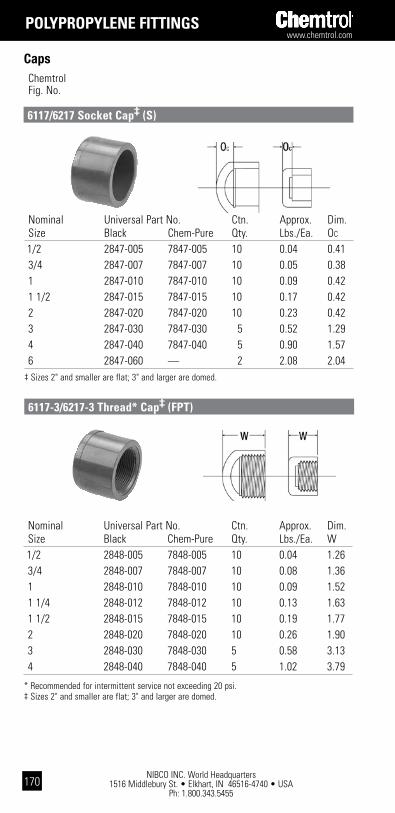
NIBCO INC. World Headquarters 1516 Middlebury St. • Elkhart, IN 46516-4740 • USA
Ph: 1.800.343.5455
www.chemtrol.com
170
Caps Chemtrol Fig. No.
6117/6217 socket cap‡ (s)
Nominal Universal Part No. Ctn. Approx. Dim. Size Black Chem-Pure Qty. Lbs./Ea. W 1/2 2848-005 7848-005 10 0.04 1.26 3/4 2848-007 7848-007 10 0.08 1.36 1 2848-010 7848-010 10 0.09 1.52 1 1/4 2848-012 7848-012 10 0.13 1.63 1 1/2 2848-015 7848-015 10 0.19 1.77 2 2848-020 7848-020 10 0.26 1.90 3 2848-030 7848-030 5 0.58 3.13 4 2848-040 7848-040 5 1.02 3.79
* Recommended for intermittent service not exceeding 20 psi.‡ Sizes 2" and smaller are flat; 3" and larger are domed.
6117-3/6217-3 thread* cap‡ (Fpt)
Nominal Universal Part No. Ctn. Approx. Dim. Size Black Chem-Pure Qty. Lbs./Ea. OC
1/2 2847-005 7847-005 10 0.04 0.41 3/4 2847-007 7847-007 10 0.05 0.38 1 2847-010 7847-010 10 0.09 0.42 1 1/2 2847-015 7847-015 10 0.17 0.42 2 2847-020 7847-020 10 0.23 0.42 3 2847-030 7847-030 5 0.52 1.29 4 2847-040 7847-040 5 0.90 1.57 6 2847-060 — 2 2.08 2.04‡ Sizes 2" and smaller are flat; 3" and larger are domed.
polYpRopYlEnE Fittings

www.chemtrol.com
NIBCO INC. World Headquarters 1516 Middlebury St. • Elkhart, IN 46516-4740 • USA
Ph: 1.800.343.5455171
Chemtrol Fig. No.
Bushings
6118/6218 Flush socket Reducer bushing (spg x s)
Nominal Universal Part No. Ctn. Approx. Design Dim. Dim. Size Black Chem-Pure Qty. Lbs./Ea. Style† LL Y** 3/4 x 1/2 2839-101 7839-101 10 0.02 S 1.27 0.43 1 x 1/2 2839-130 7839-130 10 0.04 S 1.53 0.43 1 x 3/4 2839-131 7839-131 10 0.03 S 1.53 0.45 1 1/4 x 3/4 2839-167 7839-167 10 0.09 S 1.38 0.45 1 1/4 x 1 2839-168 7839-168 10 0.07 S 1.38 0.53 1 1/2 x 1 2839-211 7839-211 10 0.11 S 1.55 0.53 1 1/2 x 1 1/4 2839-212 7839-212 10 0.07 S 1.55 0.55 2 x 1 2839-249 7839-249 10 0.18 S 1.57 0.53 2 x 1 1/2 2839-251 7839-251 10 0.13 S 1.57 0.55 3 x 2 2839-338 7839-338 5 0.38 S 2.38 0.57 4 x 3 2839-422 7839-422 5 0.49 S 2.76 0.95* Recommended for intermittent service not exceeding 20 psi.** Typical male component engagement, hand tight (L1 in ANSI B1.20.1 thread spec.) plus 1 1/2 turns.
Note: 3/4", 1", 3", and 4" sizes are hex head; 1 1/4", 1 1/2", and 2" are knurled round.† All Bushings have solid walls.
6118-3-4/6218-3-4 Flush thread* Reducer bushing (Mpt x Fpt)
Nominal Universal Part No. Ctn. Approx. Design Dim. Dim. Size Black Chem-Pure Qty. Lbs./Ea. Style† LL NN
3/4 x 1/2 2837-101 7837-101 10 0.02 S 1.28 0.43 1 x 1/2 2837-130 7837-130 10 0.04 S 1.53 0.68 1 x 3/4 2837-131 7837-131 10 0.03 S 1.53 0.56 1 1/2 x 1 2837-211 7837-211 10 0.10 S 1.78 0.68 2 x 1 2837-249 7837-249 10 0.18 S 1.91 0.81 2 x 1 1/2 2837-251 7837-251 10 0.12 S 1.91 0.56 3 x 2 2837-338 7837-338 5 0.42 S 2.38 0.90 4 x 3 2837-422 7837-422 5 0.62 S 2.76 0.91 6 x 4 2837-532 — 2 1.74 S 3.00 0.78Note: 3" and 4" sizes are hex head, 3/4", 1", 1 1/2", 2", and 6" have round heads.† All Bushings have solid walls.
polYpRopYlEnE Fittings

NIBCO INC. World Headquarters 1516 Middlebury St. • Elkhart, IN 46516-4740 • USA
Ph: 1.800.343.5455
www.chemtrol.com
172
Class 150 Flanges
Chemtrol Fig. No.
6151-h/6251-h socket Flange (s), one-piece (solid)
Nominal Universal Part No. Ctn. Approx. Dim Dim. Size Black Chem-Pure Qty. Lbs./Ea. G N 1/2 2851-H05 7851-H05 10 0.13 0.54 0.23 3/4 2851-H07 7851-H07 10 0.20 0.60 0.20 1 2851-H10 7851-H10 10 0.24 0.67 0.21 1 1/2 2851-H15 7851-H15 10 0.41 0.72 0.23 2 2851-H20 7851-H20 10 0.79 0.90 0.27 3 2851-H30 7851-H30 5 1.50 1.12 0.34 4 2851-H40 7851-H40 5 2.20 1.23 0.33 6 2851-H60 — 2 3.45 1.33 0.28
Nominal Universal Part No. Ctn. Approx. Dim. Dim. Size Black Chem-Pure Qty. Lbs./Ea. G OF
1/2 2852-H05 7852-H05 10 0.13 0.54 0.87 3/4 2852-H07 7852-H07 10 0.18 0.60 0.90 1 2852-H10 7852-H10 10 0.24 0.67 1.07 1 1/4 2852-H12 7852-H12 5 0.34 0.65 1.11 1 1/2 2852-H15 7852-H15 5 0.39 0.72 1.07 2 2852-H20 7852-H20 5 0.71 0.90 1.17 3 2852-H30 7852-H30 5 1.22 1.12 1.53 4 2852-H40 7852-H40 5 2.03 1.23 1.65* Recommended for intermittent service not exceeding 20 psi.
For flange dimensions that comply with ANSI B16.5, 150 lb., steel flanges, see page 37.
6151-h-3/6251-h-3 thread* Flange (Fpt), one-piece (solid)
polYpRopYlEnE Fittings

www.chemtrol.com
NIBCO INC. World Headquarters 1516 Middlebury St. • Elkhart, IN 46516-4740 • USA
Ph: 1.800.343.5455173
Chemtrol Fig. No.
Class 150 Flanges
6119-h/6219-h blind Flange, one-piece (solid)
Nominal Universal Part No. Ctn. Approx. Dim Dim. Size Black Chem-Pure Qty. Lbs./Ea. G OB
1/2 2853-H05 7853-H05 10 0.13 0.54 0.75 3/4 2853-H07 7853-H07 10 0.20 0.60 0.82 1 2853-H10 7853-H10 10 0.26 0.67 0.87 1 1/4 2853-H12 — 10 0.32 0.65 0.89 1 1/2 2853-H15 7853-H15 10 0.39 0.72 0.98 2 2853-H20 7853-H20 5 0.82 0.90 1.11 3 2853-H30 7853-H30 5 1.74 1.12 1.37 4 2853-H40 7853-H40 5 2.70 1.23 1.49 6 2853-H60 — 2 4.28 1.33 1.53
Nominal Universal Part No. Ctn. Approx. Dim. Dim. Size Black Chem-Pure Qty. Lbs./Ea. G N 2 2851-020 7851-020 10 0.61 0.90 0.27 3 2851-030 7851-030 5 1.16 1.12 0.34 4 2851-040 7851-040 5 1.69 1.23 0.33 6 2851-060 7851-060 2 2.66 1.33 0.28Note: One-piece webbed flanges have oblong bolt holes which permit mating with ANSI B16.5, 150 lb.; BS 1560, class 150; ISO 2084, PN10; and DIN 2532, PN10 flanges.
6151-w/6251-w socket Flange (s), one-piece (webbed design)
polYpRopYlEnE Fittings

NIBCO INC. World Headquarters 1516 Middlebury St. • Elkhart, IN 46516-4740 • USA
Ph: 1.800.343.5455
www.chemtrol.com
174
Class 150 Flanges Chemtrol Fig. No.
6151-w-3/6251-w-3 thread* Flange (Fpt), one-piece (webbed design)
Nominal Universal Part No. Ctn. Approx. Dim. Dim. Size Black Chem-Pure Qty. Lbs./Ea. G OF
2 2852-020 7852-020 5 0.56 0.90 1.17 3 2852-030 7852-030 5 0.98 1.12 1.53 4 2852-040 7852-040 5 1.62 1.23 1.65* Recommended for intermittent service not exceeding 20 psi.
Note: One-piece webbed flanges have oblong bolt holes which permit mating with ANSI B16.5, 150 lb.; BS 1560, class 150; ISO 2084, PN10; and DIN 2532, PN10 flanges.
Nominal Universal Ctn. Approx. Dim. Dim. Size Part No. Qty. Lbs./Ea. G OB
2 2853-020 5 0.59 0.90 1.11 3 2853-030 5 1.14 1.12 1.37 4 2853-040 5 1.94 1.23 1.49 6 2853-060 2 3.08 1.33 1.53Note: One-piece webbed flanges have oblong bolt holes which permit mating with ANSI B16.5, 150 lb.; BS 1560, class 150; ISO 2084, PN10; and DIN 2532, PN10.
6119-w blind Flange, one-piece (webbed design)
polYpRopYlEnE Fittings

www.chemtrol.com
NIBCO INC. World Headquarters 1516 Middlebury St. • Elkhart, IN 46516-4740 • USA
Ph: 1.800.343.5455175
Chemtrol Fig. No.
Class 150 Flanges
Flanged Fittings*– Fabricated from Molded components
Flanged Tee Flanged 90° ELL Flanged 45° ELL Nominal Approx. Dim. Approx. Dim. Approx. Dim. Size Lbs./Ea. A Lbs./Ea. A Lbs./Ea. B 1/2 0.24 2 13/32 0.21 2 13/32 0.21 2 5/32 3/4 0.37 2 23/32 0.31 2 23/32 0.31 2 15/32 1 0.48 3 3/32 0.44 3 3/32 0.43 2 23/32 1 1/2 0.94 3 31/32 0.83 3 31/32 0.76 3 13/32 2 1.64 5 7/32 1.44 4 15/32 1.32 3 27/32 3 4.97 5 15/32 3.04 5 13/32 2.70 4 25/32 4 5.30 7 3/32 4.82 7 3/32 4.43 5 25/32* Flanged fittings are produced by heat fusion of socket flanges to socket fittings with short
plain end pipe nipples.
polYpRopYlEnE Fittings
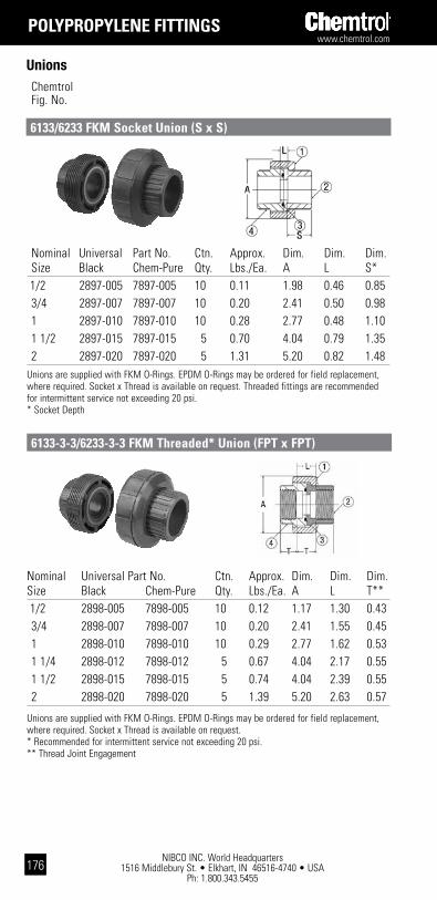
NIBCO INC. World Headquarters 1516 Middlebury St. • Elkhart, IN 46516-4740 • USA
Ph: 1.800.343.5455
www.chemtrol.com
176
Nominal Universal Part No. Ctn. Approx. Dim. Dim. Dim.Size Black Chem-Pure Qty. Lbs./Ea. A L T** 1/2 2898-005 7898-005 10 0.12 1.17 1.30 0.43 3/4 2898-007 7898-007 10 0.20 2.41 1.55 0.45 1 2898-010 7898-010 10 0.29 2.77 1.62 0.53 1 1/4 2898-012 7898-012 5 0.67 4.04 2.17 0.55 1 1/2 2898-015 7898-015 5 0.74 4.04 2.39 0.55 2 2898-020 7898-020 5 1.39 5.20 2.63 0.57
Unions are supplied with FKM O-Rings. EPDM O-Rings may be ordered for field replacement, where required. Socket x Thread is available on request. * Recommended for intermittent service not exceeding 20 psi.** Thread Joint Engagement
Unions Chemtrol Fig. No.
6133/6233 FkM socket Union (s x s)
6133-3-3/6233-3-3 FkM threaded* Union (Fpt x Fpt)
Nominal Universal Part No. Ctn. Approx. Dim. Dim. Dim. Size Black Chem-Pure Qty. Lbs./Ea. A L S* 1/2 2897-005 7897-005 10 0.11 1.98 0.46 0.85 3/4 2897-007 7897-007 10 0.20 2.41 0.50 0.98 1 2897-010 7897-010 10 0.28 2.77 0.48 1.10 1 1/2 2897-015 7897-015 5 0.70 4.04 0.79 1.35 2 2897-020 7897-020 5 1.31 5.20 0.82 1.48Unions are supplied with FKM O-Rings. EPDM O-Rings may be ordered for field replacement, where required. Socket x Thread is available on request. Threaded fittings are recommended for intermittent service not exceeding 20 psi.* Socket Depth
polYpRopYlEnE Fittings

www.chemtrol.com
NIBCO INC. World Headquarters 1516 Middlebury St. • Elkhart, IN 46516-4740 • USA
Ph: 1.800.343.5455177
Chemtrol Fig. No.
Nipples
6129 threaded* pipe nipple (Mpt x Mpt)
Length – 2" Nom. Ctn. Approx. Example of part identification Size Qty. Lbs./Ea. 1/2" x Short PP Nipple – 6129 1/2" – SH 1/2 10 0.02
Length – Close Length – Short Length – 3" Nom. Ctn. Approx. Dim. Ctn. Approx. Dim. Ctn. Approx. Size Qty. Lbs./Ea. A Qty. Lbs./Ea. A Qty. Lbs./Ea. 1/2 10 0.01 1.13 10 0.01 1.50 10 0.03 3/4 10 0.02 1.38 10 0.03 2.00 10 0.04 1 10 0.03 1.50 10 0.04 2.00 10 0.06 1 1/4 10 0.04 1.63 10 0.06 2.50 10 0.08 1 1/2 10 0.06 1.75 10 0.08 2.50 10 0.10 2 10 0.09 2.00 10 0.11 2.50 10 0.14 3 5 0.21 2.63 5 0.26 3.00 See Short 4 5 0.35 2.88 5 0.50 4.00 See Close
Length – 4" Length – 5" Length – 6" Nom. Ctn. Approx. Ctn. Approx. Ctn. Approx. Size Qty. Lbs./Ea. Qty. Lbs./Ea. Qty. Lbs./Ea. 1/2 10 0.04 10 0.05 10 0.06 3/4 10 0.06 10 0.07 10 0.09 1 10 0.08 10 0.10 10 0.12 1 1/4 10 0.12 10 0.14 10 0.18 1 1/2 10 0.14 10 0.18 10 0.21 2 10 0.20 10 0.24 10 0.30 3 5 0.37 5 0.46 5 0.59 4 See Short 5 0.72 5 0.85
*Recommended for intermittent service not exceeding 20 psi.
polYpRopYlEnE Fittings

NIBCO INC. World Headquarters 1516 Middlebury St. • Elkhart, IN 46516-4740 • USA
Ph: 1.800.343.5455
www.chemtrol.com
178
pVdF Fittings
Pipe Chemtrol Fig. No.
6500/6600-80 (1/2”-6”) plain End schedule 80 pipe (20 ft. lengths)
Pipe is ordered and specified with the Chemtrol figure number followed by the nominal size (e.g., 1 1/2" Schedule 80 PVDF Pipe – 6500-80- 1 1/2"). Weights and dimensions for all pipe may be found on page 38 of this catalog.
6501/6601 socket coupling (s x s)
Nominal Universal Part No. Ctn. Approx. Dim. Size Red Natural Qty. Lbs./Ea. N 1/2 3829-005 4829-005 5 0.12 0.28 3/4 3829-007 4829-007 5 0.16 0.27 1 3829-010 4829-010 5 0.26 0.26 1 1/2 3829-015 4829-015 2 0.49 0.25 2 3829-020 4829-020 2 0.71 0.24 3 3829-030 4829-030 2 1.43 0.21 4 3829-040 4829-040 2 2.47 0.19 6 3829-060 4829-060 1 5.49 0.21
Couplings Chemtrol Fig. No.

www.chemtrol.com
NIBCO INC. World Headquarters 1516 Middlebury St. • Elkhart, IN 46516-4740 • USA
Ph: 1.800.343.5455179
pVdF Fittings
Chemtrol Fig. No.
Couplings
Nominal Universal Part No. Ctn. Approx. Dim. Size Red Natural Qty. Lbs./Ea. L 1/2 3830-005 4830-005 5 0.12 1.98 3/4 3830-007 4830-007 5 0.16 2.22 1 3830-010 4830-010 5 0.56 2.46 1 1/2 3830-015 4830-015 2 0.49 2.95 2 3830-020 4830-020 2 0.71 3.19
6501-3-3/6601-3-3 thread coupling (Fpt x Fpt)
Nominal Universal Part No. Ctn. Approx. Dim. Size Red Natural Qty. Lbs./Ea. O 1/2 3835-005 4835-005 5 0.12 1.13 3/4 3835-007 4835-007 5 0.16 1.25 1 3835-010 4835-010 5 0.26 1.36 1 1/2 3835-015 4835-015 2 0.49 1.60 2 3835-020 4835-020 2 0.71 1.72
6503/6603 Female adapter coupling (s x Fpt)
Chemtrol Fig. No.
Adapters
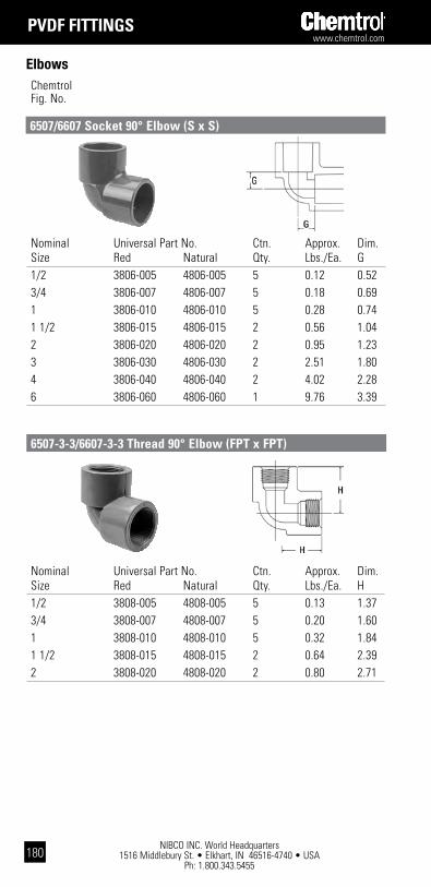
NIBCO INC. World Headquarters 1516 Middlebury St. • Elkhart, IN 46516-4740 • USA
Ph: 1.800.343.5455
www.chemtrol.com
180
Nominal Universal Part No. Ctn. Approx. Dim. Size Red Natural Qty. Lbs./Ea. G 1/2 3806-005 4806-005 5 0.12 0.52 3/4 3806-007 4806-007 5 0.18 0.69 1 3806-010 4806-010 5 0.28 0.74 1 1/2 3806-015 4806-015 2 0.56 1.04 2 3806-020 4806-020 2 0.95 1.23 3 3806-030 4806-030 2 2.51 1.80 4 3806-040 4806-040 2 4.02 2.28 6 3806-060 4806-060 1 9.76 3.39
pVdF Fittings
Elbows Chemtrol Fig. No.
6507/6607 socket 90° Elbow (s x s)
6507-3-3/6607-3-3 thread 90° Elbow (Fpt x Fpt)
Nominal Universal Part No. Ctn. Approx. Dim. Size Red Natural Qty. Lbs./Ea. H 1/2 3808-005 4808-005 5 0.13 1.37 3/4 3808-007 4808-007 5 0.20 1.60 1 3808-010 4808-010 5 0.32 1.84 1 1/2 3808-015 4808-015 2 0.64 2.39 2 3808-020 4808-020 2 0.80 2.71
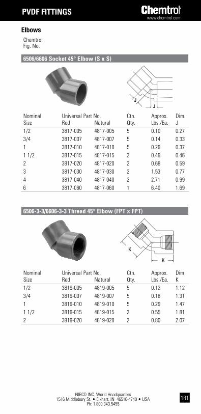
www.chemtrol.com
NIBCO INC. World Headquarters 1516 Middlebury St. • Elkhart, IN 46516-4740 • USA
Ph: 1.800.343.5455181
pVdF Fittings
Chemtrol Fig. No.
Elbows
6506/6606 socket 45° Elbow (s x s)
Nominal Universal Part No. Ctn. Approx. Dim. Size Red Natural Qty. Lbs./Ea. J 1/2 3817-005 4817-005 5 0.10 0.27 3/4 3817-007 4817-007 5 0.14 0.33 1 3817-010 4817-010 5 0.29 0.37 1 1/2 3817-015 4817-015 2 0.49 0.46 2 3817-020 4817-020 2 0.68 0.59 3 3817-030 4817-030 2 1.53 0.77 4 3817-040 4817-040 2 2.71 0.99 6 3817-060 4817-060 1 6.40 1.69
Nominal Universal Part No. Ctn. Approx. Dim Size Red Natural Qty. Lbs./Ea. K 1/2 3819-005 4819-005 5 0.12 1.12 3/4 3819-007 4819-007 5 0.18 1.31 1 3819-010 4819-010 5 0.29 1.47 1 1/2 3819-015 4819-015 2 0.55 1.81 2 3819-020 4819-020 2 0.80 2.07
6506-3-3/6606-3-3 thread 45° Elbow (Fpt x Fpt)

NIBCO INC. World Headquarters 1516 Middlebury St. • Elkhart, IN 46516-4740 • USA
Ph: 1.800.343.5455
www.chemtrol.com
182
pVdF Fittings
Tees Chemtrol Fig. No.
6511/6611 socket tee (s x s x s)
Nominal Universal Part No. Ctn. Approx. Dim. Size Red Natural Qty. Lbs./Ea. H 1/2 3805-005 4805-005 5 0.18 1.37 3/4 3805-007 4805-007 5 0.30 1.60 1 3805-010 4805-010 5 0.44 1.84 1 1/2 3805-015 4805-015 2 0.92 2.39 2 3805-020 4805-020 2 1.31 2.71
6512-3-3/6612-3-3 thread tee (Fpt x Fpt x Fpt)
Nominal Universal Part No. Ctn. Approx. Dim. Dim. Size Red Natural Qty. Lbs./Ea. G I 1/2 3801-005 4801-005 5 0.16 0.52 0.52 3/4 3801-007 4801-007 5 0.29 0.69 0.69 1 3801-010 4801-010 5 0.47 0.74 0.74 1 1/2 3801-015 4801-015 2 0.79 1.04 1.04 2 3801-020 4801-020 2 1.36 1.23 1.23 3 3801-030 4801-030 2 2.61 1.80 1.80 4 3801-040 4801-040 2 4.50 2.28 2.28 6 3801-060 4801-060 1 11.33 3.39 3.39

www.chemtrol.com
NIBCO INC. World Headquarters 1516 Middlebury St. • Elkhart, IN 46516-4740 • USA
Ph: 1.800.343.5455183
pVdF Fittings
Chemtrol Fig. No.
Plugs
6516-4/6616-4 thread plug (Mpt)
Nominal Universal Part No. Ctn. Approx. Dim. Size Red Natural Qty. Lbs./Ea. LL 1/2 3850-005 4850-005 5 0.03 1.14 3/4 3850-007 4850-007 5 0.08 1.26 1 3850-010 4850-010 5 0.10 1.48 1 1/2 3850-015 4850-015 2 0.18 1.78 2 3850-020 4850-020 2 0.26 1.89
6517/6617 socket cap (s)
Nominal Universal Part No. Ctn. Approx. Dim. Size Red Natural Qty. Lbs./Ea. OC 1/2 3847-005 4847-005 5 0.07 0.40 3/4 3847-007 4847-007 5 0.10 0.37 1 3847-010 4847-010 5 0.17 0.41 1 1/2 3847-015 4847-015 2 0.29 0.40 2 3847-020 4847-020 2 0.48 0.41Note: Caps are flat top style.
Chemtrol Fig. No.
Caps

NIBCO INC. World Headquarters 1516 Middlebury St. • Elkhart, IN 46516-4740 • USA
Ph: 1.800.343.5455
www.chemtrol.com
184
Nominal Universal Part No. Ctn. Approx. Dim. Size Red Natural Qty. Lbs./Ea. W 1/2 3848-005 4848-005 5 0.07 1.25 3/4 3848-007 4848-007 5 0.10 1.34 1 3848-010 4848-010 5 0.17 1.51 1 1/2 3848-015 4848-015 2 0.33 1.75 2 3848-020 4848-020 2 0.48 1.88
6517-3/6617-3 thread cap (Fpt)
pVdF Fittings
Caps Chemtrol Fig. No.
6518/6618 Flush socket Reducer bushing (spg x s)
Bushings Chemtrol Fig. No.
Nominal Universal Part No. Ctn. Approx. Design Dim. Dim. Size Red Natural Qty. Lbs./Ea. Style* LL NN
3/4 x 1/2 3837-101 4837-101 5 0.08 S 1.40 0.55 1 x 1/2 3837-130 4837-130 5 0.16 S 1.52 0.67 1 x 3/4 3837-131 4837-131 5 0.08 S 1.52 0.55 1 1/2 x 1 3837-249 4837-168 5 0.34 S 1.79 0.69 2 x 1 3837-249 4837-249 5 0.63 S 1.89 0.79 2 x 1 1/2 3837-251 4837-251 5 0.50 S 1.89 0.54 3 x 2 3837-338 4837-338 5 0.88 S 2.36 0.88 4 x 3 3837-422 4837-442 5 1.36 S 2.74 0.89 6 x 4 3837-532 4837-532 2 4.67 S 2.98 0.76* All Bushings have solid walls.

www.chemtrol.com
NIBCO INC. World Headquarters 1516 Middlebury St. • Elkhart, IN 46516-4740 • USA
Ph: 1.800.343.5455185
pVdF Fittings
Chemtrol Fig. No.
Bushings
6518-3-4/6618-3-4 Flush thread Reducer bushing (Mpt x Fpt)
Nominal Universal Part No. Ctn. Approx. Design Dim. Dim. Size Red Natural Qty. Lbs./Ea. Style LL Y* 3/4 x 1/2 3839-101 4839-101 5 0.05 S 1.26 0.43 1 x 1/2 3839-130 4839-130 5 0.16 S 1.52 0.43 1 x 3/4 3839-131 4839-131 5 0.08 S 1.52 0.45 1 1/2 x 1 3839-211 4839-211 5 0.19 S 1.79 0.53 2 x 1 3839-249 4839-249 5 0.35 S 1.89 0.53 2 x 1 1/2 3839-251 4839-251 5 0.22 S 1.89 0.55 * Typical male component engagement, hand tight (L1 in ANSI B1.20.1 thread spec.) plus 1 1/2
turns plus.** All Bushings have solid walls.
Chemtrol Fig. No.
Class 150 Flanges
Nominal Universal Part No. Ctn. Approx. Dim Dim. Size Red Natural Qty. Lbs./Ea. G N 1/2 3851-H05 4851-H05 5 0.25 0.53 0.19 3/4 3851-H07 4851-H07 5 0.33 0.59 0.20 1 3851-H10 4851-H10 5 0.48 0.66 0.21 1 1/2 3851-H15 4851-H15 2 0.75 0.72 0.23 2 3851-H20 4851-H20 2 1.16 0.90 0.27 3 3851-H30 4851-H30 2 2.56 1.10 0.34 4 3851-H40 4851-H40 2 3.86 1.21 0.31 6 3851-H60 4851-H60 1 5.89 1.32 0.21
6551-h/6651-h socket Flange (s), one-piece (solid)

NIBCO INC. World Headquarters 1516 Middlebury St. • Elkhart, IN 46516-4740 • USA
Ph: 1.800.343.5455
www.chemtrol.com
186
Nominal Universal Part No. Ctn. Approx. Dim Dim. Size Red Natural Qty. Lbs./Ea. G OF
1/2 3852-H05 4852-H05 5 0.25 0.53 0.87 3/4 3852-H07 4852-H07 5 0.34 0.59 0.88 1 3852-H10 4852-H10 5 0.47 0.66 1.07 1 1/2 3852-H15 4852-H15 2 0.71 0.72 1.11 2 3852-H20 4852-H20 2 1.10 0.90 1.15
6551-h-3/6651-h-3 thread Flange (Fpt), one piece (solid)
pVdF Fittings
Class 150 Flanges Chemtrol Fig. No.
6519-h/6619-h blind Flange, one-piece (solid)
Nominal Universal Part No. Ctn. Approx. Dim Dim. Size Red Natural Qty. Lbs./Ea. G OB
1/2 3853-H05 4853-H05 5 0.25 0.53 0.74 3/4 3853-H07 4853-H07 5 0.37 0.59 0.81 1 3853-H10 4853-H10 5 0.51 0.66 0.87 1 1/2 3853-H15 4853-H15 2 0.82 0.72 0.98 2 3853-H20 4853-H20 2 1.27 0.90 1.10 3 3853-H30 4853-H30 2 2.89 1.10 1.36 4 3853-H40 4853-H40 2 4.20 1.21 1.45 6 3853-H60 4853-H60 1 7.40 1.32 1.58

www.chemtrol.com
NIBCO INC. World Headquarters 1516 Middlebury St. • Elkhart, IN 46516-4740 • USA
Ph: 1.800.343.5455187
pVdF Fittings
Chemtrol Fig. No.
Class 150 Flanges
6518-3-4/6618-3-4 Flush thread Reducer bushing (Mpt x Fpt)
Nominal Universal Part No. Ctn. Approx. Dim Dim. Size Red Natural Qty. Lbs./Ea. G OF
2 3852-020 4852-020 2 0.88 0.90 1.15Note: One-piece webbed flanges have oblong bolt holes which permit mating with ANSI B16.5, 150 lb.; BS 1560, class 150; ISO 2084, PN10; and DIN 2532, PN10.
Nominal Universal Part No. Ctn. Approx. Dim Dim. Size Red Natural Qty. Lbs./Ea. G N 2 3851-020 4851-020 2 0.89 0.90 0.27 3 3851-030 4851-030 2 1.97 1.10 0.34 4 3851-040 4851-040 2 2.97 1.21 0.31 6 3851-060 4851-060 1 4.54 1.32 0.21
Note: One-piece webbed flanges have oblong bolt holes which permit mating with ANSI B16.5, 150lb.; BS 1560, class 150; IS0 2084, PN10; and DIN 2532, PN10.
6551-w-3/6651-w-3 thread Flange (Fpt), one-pc (webbed design)
6519-w/6619-w blind Flange, one-piece (webbed design)
Nominal Universal Part No. Ctn. Approx. Dim Dim. Size Red Natural Qty. Lbs./Ea. G OB
2 3853-020 4853-020 2 0.91 0.90 1.10 3 3853-030 4853-030 2 2.08 1.10 1.36 4 3853-040 4853-040 2 3.02 1.21 1.45 6 3853-060 4853-060 1 5.33 1.32 1.58Note: One-piece webbed flanges have oblong bolt holes which permit mating with ANSI B16.5, 150 lb.; BS 1560, class 150; ISO 2084, PN10; and DIN 2532, PN10.

NIBCO INC. World Headquarters 1516 Middlebury St. • Elkhart, IN 46516-4740 • USA
Ph: 1.800.343.5455
www.chemtrol.com
188
Flanged Tee Flanged 90° ELL Flanged 45° ELL Nominal Approx. Dim. Approx. Dim. Approx. Dim. Size Lbs./Ea. A Lbs./Ea. A Lbs./Ea. B 1/2 0.45 2 13/32 0.41 2 13/32 0.39 2 5/32 3/4 0.68 2 23/32 0.57 2 23/32 0.53 2 15/32 1 1.04 3 3/32 0.85 3 3/32 0.86 2 23/32 1 1/2 1.73 3 31/32 1.50 3 31/32 1.43 3 13/32 2 2.80 4 15/32 2.39 4 15/32 2.12 3 27/32* Flanged fittings are produced by heat fusion of socket flanges to socket fittings with short
plain end pipe nipples.
pVdF Fittings
Class 150 Flanges Chemtrol Fig. No.
Flanged Fittings*– Fabricated from Molded components

www.chemtrol.com
NIBCO INC. World Headquarters 1516 Middlebury St. • Elkhart, IN 46516-4740 • USA
Ph: 1.800.343.5455189
pVdF Fittings
Chemtrol Fig. No.
Unions
6533/6633 FkM socket Union (s x s)
Nominal Universal Part No. Approx. Dim. Dim. Dim. Size Red Natural Lbs./Ea. A L T* 1/2 3898-005 4898-005 0.18 1.95 1.27 0.43 3/4 3898-007 4898-007 0.32 2.36 1.53 0.45 1 3898-010 4898-010 0.47 2.75 1.58 0.53 1 1/2 3898-015 4898-015 1.11 3.98 2.38 0.55 2 3898-020 4898-020 2.24 5.13 2.61 0.57Unions are supplied with FKM O-Rings. EPDM O-Rings may be ordered for field replacement, where required. Socket x Thread is available on request. * Thread Joint Engagement
6533-3-3/6633-3-3 FkM socket Union (Fpt x Fpt)
Nominal Universal Part No. Approx. Dim. Dim. Dim. Size Red Natural Lbs./Ea. A L S* 1/2 3897-005 4897-005 0.17 1.95 0.43 0.85 3/4 3897-007 4897-007 0.31 2.36 0.48 0.98 1 3897-010 4897-010 0.46 2.75 0.44 1.10 1 1/2 3897-015 4897-015 1.04 3.98 0.78 1.35 2 3897-020 4897-020 2.17 5.13 0.80 1.48 Unions are supplied with FKM O-Rings. EPDM O-Rings may be ordered for field replacement, where required. Socket x Thread is available on request.
* Socket Depth

NIBCO INC. World Headquarters 1516 Middlebury St. • Elkhart, IN 46516-4740 • USA
Ph: 1.800.343.5455
www.chemtrol.com
190
pVdF Fittings
Class 150 Flanges Chemtrol Fig. No.
6529/6629 threaded pipe nipple (Mpt x Mpt)Example of part identification 1/2" x Short PVDF Nipple – 6129 1/2" – SH
Length – Close Length – Short Length – 3" Nom. Ctn. Approx. Dim. Ctn. Approx. Dim. Ctn. Approx. Size Qty. Lbs./Ea. A Qty. Lbs./Ea. A Qty. Lbs./Ea. 1/2 5 0.02 1.13 5 0.03 1.50 5 0.06 3/4 5 0.04 1.38 5 0.05 2.00 5 0.08 1 5 0.06 1.50 5 0.07 2.00 5 0.12 1 1/2 5 0.13 1.75 5 0.15 2.50 5 0.19 2 5 0.20 2.00 5 0.23 2.50 5 0.27
Length – 4" Length – 5" Length – 6" Nom. Ctn. Approx. Ctn. Approx. Ctn. Approx. Size Qty. Lbs./Ea. Qty. Lbs./Ea. Qty. Lbs./Ea. 1/2 5 0.08 5 0.10 5 0.12 3/4 5 0.11 5 0.14 5 0.17 1 5 0.17 5 0.21 5 0.25 1 1/2 5 0.26 5 0.34 5 0.41 2 5 0.38 5 0.48 5 0.60
6531/6631 plain End pipe nipple ( spg x spg)
Used for fusion joining flanges to fitting or for joining any Sch. 80 fitting face-to-face.
Used for joining any Sch. 80 PVDF fit-ting face-to-face.
Nominal Universal Ctn. Approx. Dim. Size Part No. Qty. Lbs./Ea. B 1/2 12 0.04 1.63 3/4 Use Figure No. 12 0.06 1.86 1 & 12 0.09 2.08 1 1/2 Nom. Size 12 0.16 2.56 2 12 0.28 2.77 3 1 0.78 3.75
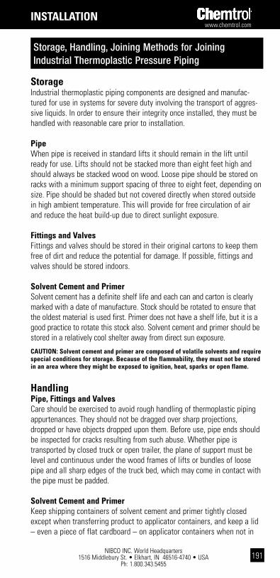
www.chemtrol.com
NIBCO INC. World Headquarters 1516 Middlebury St. • Elkhart, IN 46516-4740 • USA
Ph: 1.800.343.5455191
installation
storageIndustrial thermoplastic piping components are designed and manufac-tured for use in systems for severe duty involving the transport of aggres-sive liquids. In order to ensure their integrity once installed, they must be handled with reasonable care prior to installation.
pipeWhen pipe is received in standard lifts it should remain in the lift until ready for use. Lifts should not be stacked more than eight feet high and should always be stacked wood on wood. Loose pipe should be stored on racks with a minimum support spacing of three to eight feet, depending on size. Pipe should be shaded but not covered directly when stored outside in high ambient temperature. This will provide for free circulation of air and reduce the heat build-up due to direct sunlight exposure.
Fittings and ValvesFittings and valves should be stored in their original cartons to keep them free of dirt and reduce the potential for damage. If possible, fittings and valves should be stored indoors.
solvent cement and primerSolvent cement has a definite shelf life and each can and carton is clearly marked with a date of manufacture. Stock should be rotated to ensure that the oldest material is used first. Primer does not have a shelf life, but it is a good practice to rotate this stock also. Solvent cement and primer should be stored in a relatively cool shelter away from direct sun exposure.
caUtion: solvent cement and primer are composed of volatile solvents and require special conditions for storage. because of the flammability, they must not be stored in an area where they might be exposed to ignition, heat, sparks or open flame.
handlingpipe, Fittings and ValvesCare should be exercised to avoid rough handling of thermoplastic piping appurtenances. They should not be dragged over sharp projections, dropped or have objects dropped upon them. Before use, pipe ends should be inspected for cracks resulting from such abuse. Whether pipe is transported by closed truck or open trailer, the plane of support must be level and continuous under the wood frames of lifts or bundles of loose pipe and all sharp edges of the truck bed, which may come in contact with the pipe must be padded.
solvent cement and primerKeep shipping containers of solvent cement and primer tightly closed except when transferring product to applicator containers, and keep a lid – even a piece of flat cardboard – on applicator containers when not in
Storage, Handling, Joining Methods for Joining Industrial Thermoplastic Pressure Piping

NIBCO INC. World Headquarters 1516 Middlebury St. • Elkhart, IN 46516-4740 • USA
Ph: 1.800.343.5455
www.chemtrol.com
192
use. After each joint, wipe the respective cement and primer applicator brushes free of excess material on the top inside edge of the applicator containers and temporarily store the applicators in a container of high boiling solvent, such as MEK cleaner. This temporary brush storage container will not require a lid. Avoid prolonged breathing of solvent vapor, and when joints are being made in partially enclosed areas use a ventilating device to attenuate vapor levels. Keep solvent cement, primer and cleaners away from all sources of ignition, heat, sparks and open flames. Avoid repeated contact of the solvents with skin. Application of the cement or primer with rags and bare hands must be severely discouraged. Stiff olefin or polyester crimped-bristle brushes and other suitable applicators are safer and more effective.dangER: Extremely flammable. Vapor harmful. May be harmful if swallowed. direct contact causes eye irritation and may cause skin irritation. keep away from heat, sparks and open flame. Use only with adequate ventilation. First Aid: in case of skin contact, flush with water; for eyes, flush with water for at least 15 minutes and seek medical attention. wash contaminated clothing before reuse. if swallowed, do not indUcE VoMiting, call physician immediately.
Joining Methods for pressure pipingsolvent weldThe chemical fusion of pipe into a socket fitting is made possible by partial dissolution of the surface materials on pipe and the socket connector with a solvent primer followed by applications of solvent cement to those surfaces before pushing the joint together. Since the solvent cement contains dissolved parent material, there is a commingling of pipe, cement and fitting materials as the joint is made and twisted 90°, such that upon evaporation of the volatile solvents a single residual material is chemically bonded or fused. Traditional cement, or glue, i.e. foreign material carried in an organic solvent or water base and acting as an alien interface for bonding two surfaces together, has not been used for making thermoplastic piping joints. Solvent welding is an easy and inexpensive joining method for pipe. However, in order to be a candidate for this method, the piping material itself must be soluble in relatively volatile organic solvent(s). PVC, CPVC and ABS are such materials commonly used for commercial and industrial piping applications.
thermo-Fusion (heat Fusion)The heat fusion of pipe into a socket fitting is made possible by partial melting of the surface materials on pipe and the socket connector with electrically heated female and male anvils, respectively, applied to those surfaces before pushing the joint together. Since the heated anvils are designed to diametrically interfere with the pipe and socket in matching geometric cones; and the plastic melt swells when passing through the phase change from solid material; there is a commingling of pipe and fitting materials as the joint is stabbed together. Upon cooling a single material is solidly fused. There is a similar joining method called butt fusion where pipe-to-pipe or pipe-to-fitting-face joints are made by partial melting the ends to be joined by holding them against an electrically heated plate, and then pushing the butt ends together. However, because
installation

www.chemtrol.com
NIBCO INC. World Headquarters 1516 Middlebury St. • Elkhart, IN 46516-4740 • USA
Ph: 1.800.343.5455193
of problems associated with longitudinal alignment, uneven cooling and differential melt pressure during cooling, butt fusion joining should never be used for conveying hazardous liquids, particularly above ground. These joints have been known to shatter without warning too frequently for industrial chemical usage. Butt fusion is an ideal joining method for under ground low-pressure gas piping and high-purity process water systems.
thread (tapered national pipe threads)Threaded joints are sometimes used for emergency repairs and when a piping system must be dismantled for occasional cleaning or modifications. Since threading results in a reduction in the effective wall thickness of the pipe, the pressure rating of threaded pipe is reduced to one-half that of unthreaded pipe, i.e. pipe joined by solvent cementing or heat fusion. Because of the serious strength reduction, only Sch. 80 or greater wall thickness of plastic pipe is recommended for threading – never Sch. 40. Threaded joints are not a recommended method for material transition at vessels, equipment and pumps because external mechanical stresses are concentrated at the notch sensitive plastic thread – metals are typically stronger than plastic by five or more orders of magnitude. See the Pipe Union joint section below for the proper solution for material transition.A great difference in the thermal coefficients of expansion, between the materials to be joined, makes the threaded joint more susceptible to leakage. Threaded polypropylene systems are not recommended for pressure piping because of the material's extremely low modulus of elasticity and sensitivity to notching (the joints will leak in time).
other Mechanical JointsFlangeFlanges are an old method of joining, but they continue to be used extensively on vessels, equipment and pumps. Particularly in sizes above 3", flanges are the easiest way to disassemble piping for cleaning and modification or maintenance of equipment, so joining method and location within the system are important factors in planning for maintenance efficiency. Socket fittings and valves are flanged with plain-end short nipples by solvent welding or heat fusing (depending on material type) both joints. Flanges are similarly joined to straight pipe runs, or they can be threaded.
pipe UnionParticularly in sizes 3" and below, unions are the easiest and most reliable way to disassemble piping for cleaning and modification or maintenance of equipment. They are, unfortunately, too often overlooked in planning the design of thermoplastic piping systems. The factors that make threaded joints unrealistic as a method for transition between materials are given in the paragraph above discussing threads. These reasons catalyzed Chemtrol development of: True Union Valves; Pipe Union with end connectors and union nuts that are interchangeable with the True Union Valve; and stainless steel or brass transition end connectors that are interchangeable with plastic end connectors for both the Pipe Unions and True Union
installation
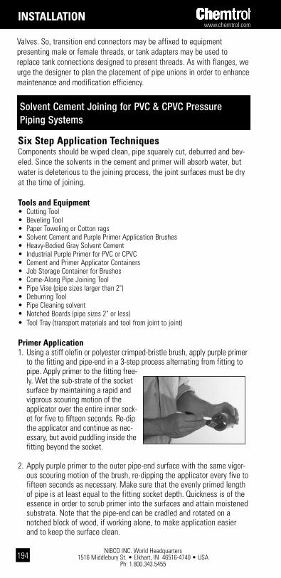
NIBCO INC. World Headquarters 1516 Middlebury St. • Elkhart, IN 46516-4740 • USA
Ph: 1.800.343.5455
www.chemtrol.com
194
installation
Solvent Cement Joining for PVC & CPVC Pressure Piping Systems
six step application techniquesComponents should be wiped clean, pipe squarely cut, deburred and bev-eled. Since the solvents in the cement and primer will absorb water, but water is deleterious to the joining process, the joint surfaces must be dry at the time of joining.
tools and Equipment• Cutting Tool• Beveling Tool• Paper Toweling or Cotton rags• Solvent Cement and Purple Primer Application Brushes• Heavy-Bodied Gray Solvent Cement• Industrial Purple Primer for PVC or CPVC• Cement and Primer Applicator Containers• Job Storage Container for Brushes• Come-Along Pipe Joining Tool• Pipe Vise (pipe sizes larger than 2")• Deburring Tool• Pipe Cleaning solvent • Notched Boards (pipe sizes 2" or less)• Tool Tray (transport materials and tool from joint to joint)
primer application1. Using a stiff olefin or polyester crimped-bristle brush, apply purple primer
to the fitting and pipe-end in a 3-step process alternating from fitting to pipe. Apply primer to the fitting free-ly. Wet the sub-strate of the socket surface by maintaining a rapid and vigorous scouring motion of the applicator over the entire inner sock-et for five to fifteen seconds. Re-dip the applicator and continue as nec-essary, but avoid puddling inside the fitting beyond the socket.
2. Apply purple primer to the outer pipe-end surface with the same vigor-ous scouring motion of the brush, re-dipping the applicator every five to fifteen seconds as necessary. Make sure that the evenly primed length of pipe is at least equal to the fitting socket depth. Quickness is of the essence in order to scrub primer into the surfaces and attain moistened substrata. Note that the pipe-end can be cradled and rotated on a notched block of wood, if working alone, to make application easier and to keep the surface clean.
Valves. So, transition end connectors may be affixed to equipment presenting male or female threads, or tank adapters may be used to replace tank connections designed to present threads. As with flanges, we urge the designer to plan the placement of pipe unions in order to enhance maintenance and modification efficiency.

www.chemtrol.com
NIBCO INC. World Headquarters 1516 Middlebury St. • Elkhart, IN 46516-4740 • USA
Ph: 1.800.343.5455195
installation
3. Re-apply primer to the fitting socket in the same manner. When a contin-uous peel of a few thousandths of an inch thickness can be scraped from the primed surface with an edge, such as a knife blade, the substrate has been adequately primed for a joint. With practice one will learn to observe a slight tacki-ness and swell in the surfaces when priming is adequate. Alternate applications of the primer always start with the female component. Cementing should not begin until priming is adequate.
solvent cement application4. Before the primer dries, continue the alternating surface approach by
applying solvent cement to the pipe and fitting in a 3-step process. Use a second plastic crimped-bristle brush to spread a continuous film of cement on the outer pipe-end surface for a length at least equal to that of the fitting socket depth. The cement film should be such that it does not run as a sheet and drool from the exterior or into the pipe interior. And the film thickness need be only thick enough to trap the continuing penetration of solvent into the pipe substrate.
5. While the moistened substrate of the fitting socket is still soft and swollen from priming, quickly spread a continuous film of solvent cement onto the entire socket surface. Avoid puddling and run-off of the cement anywhere in the fitting, or beyond the socket depth in belled-end pipe. The cement film need be only thick enough to trap the con-tinuing penetration of solvent into the substrate and to provide an immediate and continuous wet filet around the pipe chamfer during its eminent insertion into the fitting socket. Most of this cement will be pushed ahead by the pipe throughout its insertion to the full depth of the socket. A final excess of cement at the bottom of the socket should be avoided because it cannot be removed. Large puddles formed inside the pipe and/or fitting bore serve to dramatically extend the drying time of these solvent affected areas, which translates to reduced strength of the parent material until drying does occur. Mounds of dried cement may also ultimately act as blockages to fluid flow, resulting in unacceptable pressure loss.
6. Put a second coat of solvent cement on the pipe-end. This completes the six steps of alternate surface application for a joint – three of prim-er and three of cement – starting with the female component. Cement layers on the pipe must be without voids and sufficient to provide an immediate and continuous wet filet around the socket entrance radius/

NIBCO INC. World Headquarters 1516 Middlebury St. • Elkhart, IN 46516-4740 • USA
Ph: 1.800.343.5455
www.chemtrol.com
196
chamfer during the eminent insertion of pipe into the fitting socket. Excess cement will be pushed off the pipe throughout its insertion to the full depth of the fitting socket. However, it is critical that the two wet beads – an inside one around the pipe chamfer and an outside one around the socket chamfer – be maintained to form vacuum seals while joining. Although much of the cement will be scraped off both the pipe and socket during joint insertion, some must be redrawn, by vacuum, to back-fill the diametrical gap between pipe and fitting socket. Air will back-fill the joint if either of the wet bead dynamic seals is broken during joint insertion, resulting in a loss of bonding area.
crew sizeObviously, the 6-step application method has a joining crew size of one in mind. When the crew size is increased to two, the 6-step principals must be modified such that each crewmember has their own set of primer and cement brushes and each would attend to the application of both solu-tions to a single joint surface. The total time to prime and spread cement to each surface is essentially the same when the 6-step concept is mim-icked by a crew of two. A crew of two should be strongly considered for pipe sizes 2" through 4" and should be man-datory for larger sizes. A come-along type pipe-joining tool, similar to that manufactured by Reed Manufacturing, Erie, PA, is required for the 10" and larger sizes
pipe insertionImmediately upon finishing the application of cement, and before it begins to dry, the pipe must be inserted squarely into the fitting socket. Too much time has elapsed if either of the surface films has dried to the point that the film folds in the socket chamfer upon pipe insertion, rather than form-ing a wet bead at that location. Rotation of the pipe ⁄ turn in the socket, following pipe insertion to the full socket depth, completes the joint. This encourages complete distribution of the cement and its commingling with joint surfaces. In addition to a crew size of two being mandatory for 6" and larger pipe, rotation of the pipe in the fitting may be omitted for these sizes.
After completing the joint it must be held together for a brief time while the cement begins to dry. This is to prevent the pipe from squirting back out of the fitting socket. The phenomena occurs because fresh cement is an excellent lubricant and product standards dictate the socket to be
installation
www.chemtrol.com
NIBCO INC. World Headquarters 1516 Middlebury St. • Elkhart, IN 46516-4740 • USA
Ph: 1.800.343.5455197
tapered, with the minimum entrance diameter equaling the maximum pipe diameter and the diameter at the bottom of the socket creating a statisti-cal interference with the pipe diameter. Therefore, the joint must be held together for a minimum of 10 to 15 seconds – a little longer for larger sizes. For pipe sizes 6" and larger the holding time may be one to three minutes. If any pipe back-out does occur, the potential for joint failure/leakage is unacceptably great.
Excess CementWipe off all excess cement from the circumference of the pipe and fitting immediately after the joint holding period and before the cement begins to harden. The localized quantity of cement will affect solvent evaporation by extending the drying time of the pipe. Then, gently place the joint onto a level surface to complete the hardening stage before further handling.
Joint drying time guidelinesBecause of the variety of these unpredictable conditions that may exist from job to job, Chemtrol can only offer the following general recommen-dations relative to PVC and CPVC joint drying times:
1. It is best if the actual joining is done in atmospheric temperature above 35/40° F and below 90° F when the joint components are exposed to direct sun.
2. It is best if all joints can have 72 hours of drying time elapse for all sizes of pipe and drying temperatures before the joint is subjected to any appreciable pressure on a fulltime basis.
The installation manager must assume the risk of deciding when PVC or CPVC joints are sufficiently dry for movement or handling, initiating low pressure testing, applying high pressure testing and/or subjecting the new system to the maximum allowable fulltime working pressure. Chemtrol offers the following drying times as a guide in aiding the installer, engineer, owner or other interested parties in making these decisions. The drying times are based on a combination of past field experience and laboratory tests.
The installation instructions contained herein are recommendations. It is the responsibility of the installer to follow industry best practices for installation and to comply with all applicable codes and regulations.
HandlingDuring the initial hardening of the cement, which begins about two min-utes after its application (on small sizes), be careful not to move or disturb the joint less the bond of fragile material be broken. A guide for drying times prior to handling a joint appears below.
installation
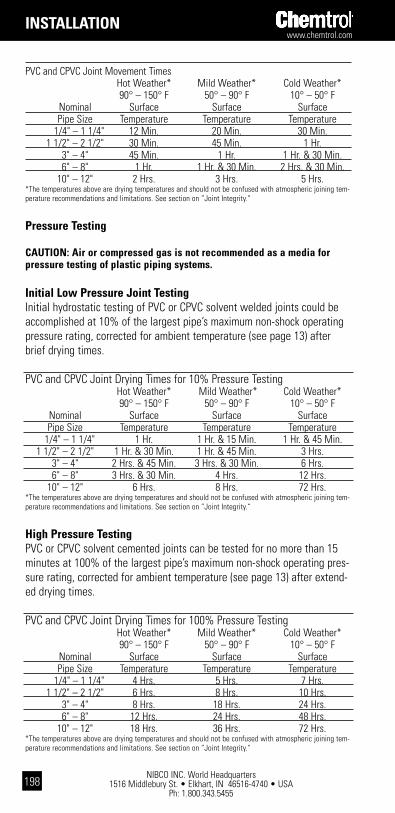
NIBCO INC. World Headquarters 1516 Middlebury St. • Elkhart, IN 46516-4740 • USA
Ph: 1.800.343.5455
www.chemtrol.com
198
PVC and CPVC Joint Movement Times Hot Weather* Mild Weather* Cold Weather* 90° – 150° F 50° – 90° F 10° – 50° F Nominal Surface Surface Surface Pipe Size Temperature Temperature Temperature 1/4" – 1 1/4" 12 Min. 20 Min. 30 Min. 1 1/2" – 2 1/2" 30 Min. 45 Min. 1 Hr. 3" – 4" 45 Min. 1 Hr. 1 Hr. & 30 Min. 6" – 8" 1 Hr. 1 Hr. & 30 Min. 2 Hrs. & 30 Min. 10" – 12" 2 Hrs. 3 Hrs. 5 Hrs.*The temperatures above are drying temperatures and should not be confused with atmospheric joining tem-perature recommendations and limitations. See section on ”Joint Integrity.“
Pressure Testing
CaUTION: air or compressed gas is not recommended as a media for pressure testing of plastic piping systems.
Initial Low Pressure Joint TestingInitial hydrostatic testing of PVC or CPVC solvent welded joints could be accomplished at 10% of the largest pipe’s maximum non-shock operating pressure rating, corrected for ambient temperature (see page 13) after brief drying times.
PVC and CPVC Joint Drying Times for 10% Pressure Testing Hot Weather* Mild Weather* Cold Weather* 90° – 150° F 50° – 90° F 10° – 50° F Nominal Surface Surface Surface Pipe Size Temperature Temperature Temperature 1/4" – 1 1/4" 1 Hr. 1 Hr. & 15 Min. 1 Hr. & 45 Min. 1 1/2" – 2 1/2" 1 Hr. & 30 Min. 1 Hr. & 45 Min. 3 Hrs. 3" – 4" 2 Hrs. & 45 Min. 3 Hrs. & 30 Min. 6 Hrs. 6" – 8" 3 Hrs. & 30 Min. 4 Hrs. 12 Hrs. 10" – 12" 6 Hrs. 8 Hrs. 72 Hrs.*The temperatures above are drying temperatures and should not be confused with atmospheric joining tem-perature recommendations and limitations. See section on ”Joint Integrity.“
High Pressure TestingPVC or CPVC solvent cemented joints can be tested for no more than 15 minutes at 100% of the largest pipe’s maximum non-shock operating pres-sure rating, corrected for ambient temperature (see page 13) after extend-ed drying times.
PVC and CPVC Joint Drying Times for 100% Pressure Testing Hot Weather* Mild Weather* Cold Weather* 90° – 150° F 50° – 90° F 10° – 50° F Nominal Surface Surface Surface Pipe Size Temperature Temperature Temperature 1/4" – 1 1/4" 4 Hrs. 5 Hrs. 7 Hrs. 1 1/2" – 2 1/2" 6 Hrs. 8 Hrs. 10 Hrs. 3" – 4" 8 Hrs. 18 Hrs. 24 Hrs. 6" – 8" 12 Hrs. 24 Hrs. 48 Hrs. 10" – 12" 18 Hrs. 36 Hrs. 72 Hrs.*The temperatures above are drying temperatures and should not be confused with atmospheric joining tem-perature recommendations and limitations. See section on ”Joint Integrity.“
installation

www.chemtrol.com
NIBCO INC. World Headquarters 1516 Middlebury St. • Elkhart, IN 46516-4740 • USA
Ph: 1.800.343.5455199
general comments and hintsdo’s and don’ts
do:• Clean and prepare pipe and fitting (see Preparation for Joining, page 22).• Use the proper applicators (see Selection of Applicators for…, page 23).• Scrub primer into joint surfaces until a lemon peel may be curled with an edge.• Apply Cement while the primer is still moistened.• Maintain two wet beads at the pipe and fitting chamfers throughout joint
insertion.• Follow the instructions completely.
don’t:• Attempt to solvent weld in wet and/or wind without shielding.• Solvent weld below 35° or above 90° F under direct sun exposure without
precautions (see Hot and Cold Weather Cementing below).• Discard leftover cans of solvent in trench with piping. Concentrated fumes can
cause piping failure. • Skip any priming or cementing steps.• Skimp with cement on pipe or overdo cement in sockets, but apply enough for
wet bead formation during joint insertion.
hot weather cementingHot weather can be the nemesis of solvent cementing. As the temperature and/or wind increase, the rate of solvent evaporation quickens. Hence, it becomes more difficult to keep primed surfaces moistened. Even the cement itself can begin to “film over” prior to joining. Rather than using hot weather as an excuse to compromise the functional elements required for reliable joining, the problem must be overcome by adjusting the approach to priming, cement application and pipe insertion techniques in order to appropriately reduce the lapsed joining time. As corrective measures to combat wind and/or temperature in excess of 90° F, the following may be done:
1. Increase the crew size and organize the team to achieve speed while making no compromise to functional performance.
2. Construct a windscreen from polyethylene film or tenting around the joint and crew.
3. Shade the pipe, fittings, valves and solvent materials from the sun prior to joining in order to eliminate heat absorption by the dark color. Fittings, valves and solvent supplies may be kept in a box. Shading the pipe to be joined may be more difficult, but not impossible. Under adequate lighting, the joining may be done at night or early morning.
cold weather cementingSolvent in the primer and cement will not evaporate as readily when the temperature is below 35°/40° F. Severe scouring with a stiff bristle brush is required to work the primer solvents into the surfaces. Secondly, it takes appreciably more time for the solvents to evaporate once the joint is made. Therefore, joints must be held together longer to prevent the pipe backing out of the socket. Joints must be left undisturbed longer to
installation

NIBCO INC. World Headquarters 1516 Middlebury St. • Elkhart, IN 46516-4740 • USA
Ph: 1.800.343.5455
www.chemtrol.com
200
installation
prevent breaking the bond by movement. And joints must be given longer drying times before pressurization. We offer the following common sense recommendations if solvent cementing must be done when the temperature approaches freezing:
Store the pipe, fitting, valves and cementing supplies in a heated area until you are ready to use them. Also, water or moisture is an enemy and frost is commonplace at near freezing temperature. So, the pipe and fittings must be kept dry prior to joining and the joints should be kept dry until the cement has had sufficient time to set – not dry, just set so they can be moved without fear of breaking the initial bond.
1. Pre-fab as much of the system as possible in a heated work area. By using flange or union connections for system erection, the number of in-place cemented joints can be minimized.
2. Field joints that must be made outside should be protected with a portable shelter, preferably black to absorb heat from the sun, and otherwise heated indirectly to produce a 40° F surface temperature on the pipe, fittings, valves and cementing supplies. The shelter should remain in place until the joint is set. And you can figure the set time to be roughly twice what it would be for a 70° joint. Good ventilation of the shelter is an absolute safety necessity for worker health and fire prevention reasons.
caUtion: do not attEMpt to spEEd thE dRYing oF thE cEMEnt bY applYing diREct hEat to thE solVEnt wEldEd Joint. Forced rapid drying by heating with an electric blow drier, for example, will cause the cement solvents to boil off, forming porosity, bubbles and blisters in the cement film.
Joint integrityIn hot, mild or colder weather, if the basic joining steps are followed with discipline, the chemical fusion joining method for thermoplastic piping is extremely reliable and cost efficient. Because of significant contributions to commercial and industrial construction, both thermoplastic piping and solvent welding are here to stay. By virtue of their permanent resistance to chemical attack and undeniable economic impact, value engineering has reached the stage where even mundane processes, such as water disinfection, or exotic processes, such as bulk and dilute acid feed, are absolutely dependant upon PVC or CPVC piping with solvent cemented joints. In spite of the higher standards of skill required for industrial chemical installations, relative to the marginal standards required for domestic small diameter utility applications, we are beyond the time when joint failure can be excused because of inexperience or poor workmanship. Since the difference between cementing a joint and gluing it is common knowledge today, the 40 plus year-old technology for solvent cementing justifiably demands professional discipline in its execution. As a result, the low bidder for any PVC or CPVC piping installation can reasonably be expected to exercise control over joining performance.

www.chemtrol.com
NIBCO INC. World Headquarters 1516 Middlebury St. • Elkhart, IN 46516-4740 • USA
Ph: 1.800.343.5455201
installation
solvent cement Usage EstimatesThe PVC and CPVC solvent cement usage estimates given in the table below should only be considered as a guideline. Actual usage could vary according to a wide variety of installation conditions. Further, these estimates should in no way be used to restrict the liberal instructions in the Six Step Application Techniques starting on page 24.
Number of Joints per Container Size Pipe Size Pint Quart Gallon 1⁄2" 130 260 1040 3⁄4" 80 160 640 1" 70 140 560 11⁄4" 50 100 400 11⁄2" 35 70 280 2" 20 40 160 21⁄2" 17 34 136 3" 15 30 120 4" 10 20 80 6" N/R 8 32 8" N/R 3 12 10" N/R N/R 10 12" N/R N/R 6
Within the marketplace, one will find heating anvils for the fusion joining of IPS drainage, metric pressure and IPS Polyethylene gas piping – none of which will satisfactorily join Chemtrol® fittings with pressure pipe for reasons of socket length and/or diametrical fit. Chemtrol Heating Anvils (heating face sets) are designed to diametrically interfere with the pipe, and principally the socket connection, so as to create matching geometric cones as the plastic melt swells when passing through the phase change from solid material. Therefore, NIBCO obviously can not warrant pipe, fittings and valves, which are not joined with Chemtrol Heating Anvils (heating face sets) as well as depth gages and pipe clamps, where applicable.
waRning: Failure to use chemtrol heating face sets could result in improperly fused joints and damage to property.
The heating tool must be kept clean at all times. Wipe away residual material from heat faces with a clean rag. Periodic applications of silicone spray to heat faces will assist in maintaining performance. Chemtrol recommends 3M Company's Aerosol Spray (Product #62-4678-4930-3) "food grade." 3M Technical Customer Service Center can be reached at 800-362-3550.
Thermo-Seal (Socket Fusion) Joining for Polypropylene and PVDF (KYNAR®) Pressure Piping Systems
Kynar® is a registered trademark of Arkema Inc.

NIBCO INC. World Headquarters 1516 Middlebury St. • Elkhart, IN 46516-4740 • USA
Ph: 1.800.343.5455
www.chemtrol.com
202
installation
six steps of Joining Mechanics for hand-held heat-toolscrew sizeFor the sake of clarity of these instructions, we are assuming the usual installation crew of two, while prefabricating at a workbench. The first installer is in charge of the socket connection and will be referenced as installer #1, for simplicity. The second team member is in charge of the pipe end during the joining process and he shall be referenced as installer #2.
tools and Equipment• Pipe Cutting Tool• Pipe Beveling tool• Hand-Held Heat-Tools• Depth Gauges• Pipe Clamps w/inserts• Heating Anvils for male and female piping components• Timer• Thermal Blanket• Auxiliary Handle for Heat-Tool• Hex-Key wrenches for Heating Anvils and Pipe Clamp inserts• Thermostat Adjustment tool• Joining Instructions• Deburring tool• Pipe Cleaning solvent• Paper Toweling or Clean Wipes• Silicone Lubricant
1. Installer #2 gives the Heating Anvils (heat face sets) a light fogging of silicone spray, making sure that the spray is directed into the Pipe Anvil and that some of the fog is directed at the top, bottom and both sides of the Fitting Anvil. Meanwhile, installer #1 grasps the pipe and inserts the pipe end to the bottom of the Pipe Gauge. Wipe excess spray from the Anvils with a clean paper towel.
2. Installer #1 may need to adjust the clamp screw on the pliers, which governs the clamp opening. The Pipe Clamp must snuggly grasp the pipe, but not crush it out-of-round. He should then attach the Pipe Clamp w/insert to the pipe by butting the flush surface against the face of the Depth Gauge while installer #1 continues holding the Gauge against the pipe end. Installer #2 should use his index and middle fingers to push both halves of the Pipe Clamp to insure they are flush against the Depth Gauge face.

www.chemtrol.com
NIBCO INC. World Headquarters 1516 Middlebury St. • Elkhart, IN 46516-4740 • USA
Ph: 1.800.343.5455203
installation
3. Simultaneously, installer #1 should place the pipe and installer #2 should place the socket connection squarely on the Heating Anvils (heat face sets) so that the ID of the connection and the OD of the pipe are in contact with the heating surfaces. Care should be taken to insure that neither the pipe or socket connection are cocked as they are pushed in/on the Anvils. The Pipe Clamp’s simple job is to precisely mark the location of socket depth on the pipe, so installer #1 should not use the tool as a push bar. Don’t allow the clamp to slip on the pipe and lose the opportunity for making a quality joint. The socket connection will always have more initial interference with its Anvil than the pipe, so the force applied by installer #2 will probably be less than the force required from installer #1 as they match insertion rates on/in their respective Anvils. The plastic components will only slide on/in the Anvils when the plastic melts and allows forward progress. Therefore, the plastic components should not be moved by rocking or twisting them on their Anvils in an effort to hasten penetration. A solid steady force is all that is required. It is the responsibility of installer #2 to penetrate at the same rate as installer #1 so that both arrive at the same time at the home position on the Anvils. Progress is good when both installers see that the plastic melt bead forming on the male Anvil at the entrance radius/chamfer of the socket is uniform around the socket entrance.
4. Home positions on the Heating Anvils (heat socket set) are when the melt bead in the entrance radius/chamfer of the socket connection touches the mounting flange of the male Heating Anvil and the Pipe Clamp uniformly touches the face of the female Heating Anvil. do not sqUEEZE thE MElt bEad. YoU aRE in thE hoME position. With practice, installers will learn that the melt bead is an excellent reference for proper alignment. As the joint components of the installers approach their respective home positions of insertion on/in the Heating Anvils the installer #1 should make sightings of his bead distance from home position on top, bottom and both sides of the mounting flange. Installer #1 should insure the bead touches the Anvil flange – completely around the fitting – all at once. As the touch is made, he should stop. Installer #2, equaling the rate of his pipe penetration with the rate of fitting penetration in/on the respective Anvils, should also make 360° sightings of his distance from the Pipe Clamp to Anvil face. Installer #2 must insure the face of his Anvil touches the Pipe Clamp – completely around the pipe – all at once. This is the first reason for insuring that one end of the Pipe Clamp w/inserts is a true surface. As the touch is made he should also stop. Both installers should hold their positions for the prescribed time in the Table of Thermo-Fusion Socket Heating Times. Installer #1 must continue to monitor the melt bead, while holding the socket connection in the home position. Installer #2 must concentrate on holding the Pipe Clamp flush against the face of the female Heating Anvil to allow heat to transfer into the pipe and fitting surfaces to be fusion bonded.
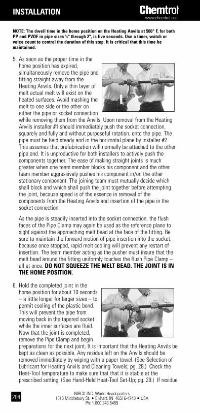
NIBCO INC. World Headquarters 1516 Middlebury St. • Elkhart, IN 46516-4740 • USA
Ph: 1.800.343.5455
www.chemtrol.com
204
installation
notE: the dwell time in the home position on the heating anvils at 500° F, for both pp and pVdF in pipe sizes 1⁄2" through 2", is five seconds. Use a timer, watch or voice count to control the duration of this step. it is critical that this time be maintained.
5. As soon as the proper time in the home position has expired, simultaneously remove the pipe and fitting straight away from the Heating Anvils. Only a thin layer of melt actual melt will exist on the heated surfaces. Avoid mashing the melt to one side or the other on either the pipe or socket connection while removing them from the Anvils. Upon removal from the Heating Anvils installer #1 should immediately push the socket connection, squarely and fully and without purposeful rotation, onto the pipe. The pipe must be held steady and in the horizontal plane by installer #2. This assumes that prefabrication will normally be attached to the other pipe end. It is unproductive for both installers to actively push the components together. The ease of making straight joints is much greater when one team member blocks his component and the other team member aggressively pushes his component in/on the other stationary component. The joining team must mutually decide which shall block and which shall push the joint together before attempting the joint, because speed is of the essence in removal of the components from the Heating Anvils and insertion of the pipe in the socket connection.
As the pipe is steadily inserted into the socket connection, the flush faces of the Pipe Clamp may again be used as the reference plane to sight against the approaching melt bead at the face of the fitting. Be sure to maintain the forward motion of pipe insertion into the socket, because once stopped, rapid melt cooling will prevent any restart of insertion. The team member acting as the pusher must insure that the melt bead around the fitting uniformly touches the flush Pipe Clamp – all at once. do not sqUEEZE thE MElt bEad. thE Joint is in thE hoME position.
6. Hold the completed joint in the home position for about 10 seconds – a little longer for larger sizes – to permit cooling of the plastic bond. This will prevent the pipe from moving back in the tapered socket while the inner surfaces are fluid. Now that the joint is completed, remove the Pipe Clamp and begin preparations for the next joint. It is important that the Heating Anvils be kept as clean as possible. Any residue left on the Anvils should be removed immediately by wiping with a paper towel. (See Selection of Lubricant for Heating Anvils and Cleaning Towels; pg. 28.) Check the Heat-Tool temperature to make sure that that it is stable at the prescribed setting. (See Hand-Held Heat-Tool Set-Up; pg. 29.) If residue

www.chemtrol.com
NIBCO INC. World Headquarters 1516 Middlebury St. • Elkhart, IN 46516-4740 • USA
Ph: 1.800.343.5455205
installation
deposits on the Heating Anvils following the making of joints persists, try increasing the silicone spray to thoroughly coat the applicable surfaces and/or reduce the prescribed heating time by increments of 10 – 20%. Be cautious in the reduction of time for sizes 2" and below. Do not waver from the prescribed temperature settings. (See Thermo-Fusion Socket Heating Times.)
caUtion: Molten plastic material can cause severe burns. avoid contact with the hot plastic and heat-tool. it is always a good idea to drape a thermal blanket over a hot heat-tool – hand-held or bench-mount – when the installers must leave the work area. a – caution hot – sign posted on the workbench should be out at all times during and after use.
superior design and construction Features of bench-Mount Joining Machinedescription of basic components Bench-Mount Joining Machines are an outgrowth of the prefabrication concept. Each of the three Chemtrol® machines have a temperature controlled heat-plate attached to the machine, which can be swung from centerline of the machine to a rear position that does not interfere with machine travel perpendicular to the heat-plate. The PTFE clad Anvils (heat face sets), which heat pipes and socket connections, are used interchangeably for Hand-Held heat-plates and Bench-Mount heat-plates. All sizes of Heating Anvils (heat face sets) mount to Bench-Mount heat-plates with 3/8" standard bolts that pass through a clearance hole in the dead center of its heat-plate.

NIBCO INC. World Headquarters 1516 Middlebury St. • Elkhart, IN 46516-4740 • USA
Ph: 1.800.343.5455
www.chemtrol.com
206
installation
Features Forming the Foundation of Machines No. Name / Element
1 Machine base, Aluminum casting for rigidity and minimum weight during movement
2 Two Steel Rods with hard chrome finish, which are firmly attached to each end of machine base, act as the machine ways.
3 Pipe Sled, rides freely and precisely toward or away from center on ways through Bushings
4 Fitting Sled, rides freely and precisely toward or away from center on ways through Bushings
5 Rack and Pinion provides in-and-out movement of the sleds on the machine ways
6 Hand-Wheel, machine-tool spoke type, turned by operator clockwise or counter clockwise respectively, to drive both sleds together or apart at same rate – each a slave to the other.
7 Depth Gauge Stroke-Limiter, spring-loaded plunger with latch on operator’s right, which he can depress to engage the fitting sled as the operator brings both sleds together. This position correctly measures pipe projection from the entrance of a socket connection to the Prismatic Pipe Clamping Jaws 8 Joint Insertion Stroke-Limiter assembly, passes through the pedestal block that holds the heat-plate handle. It is located in front of the operator. An indexable steel tube having notches cut into the periphery at the end of the tube, which correspond to the joint insertion lengths for each pipe size, will be caught by an arresting arm, mounted on the bottom of the pipe sled.
9 Knob Handle for set-screw, which locks the pipe sled in place by bearing on the front machine Steel Rod way.
The tops of the fitting and pipe sleds are finished flat, relative to their bushing bearing holes. Each sled has mounted upon it a miniature Vise, which simultaneously advances or retracts the Holder-Blocks on each sled by the operator turning a Lead-Screw, fitted through Brass Bushings in each Holder-Block. Each Vise is centered on its sled by means of a slot in the sled and a dovetail projecting from the bottom of the Vice Base. This locating concept also insures that the independent action of each Vise is perfectly perpendicular to the transverse line of movement for the sleds.
2 54
89
7
1
3
6

www.chemtrol.com
NIBCO INC. World Headquarters 1516 Middlebury St. • Elkhart, IN 46516-4740 • USA
Ph: 1.800.343.5455207
installation
Features of the pipe and Fitting clamping Vises No. Name / Element
1 Transverse Fitting and Pipe Vise Bases, permanently located in the longitudinal and horizontal planes by a slot in the top of the sleds and a dovetail projecting from the bottom of Vise Bases
2 Two Pair of Vice Holder-Blocks, each pair forming the Fitting Vise on the operator’s right or the Pipe Vise on the operators left. The Clamping Jaws mount to the Holder-Blocks such that the four tangent points on each set of Jaws grasping the product (pipe or fitting) have equal radii to the dead center of the product, which coincides with the centerline of the machine
3 Pair of Fitting Prismatic (vee type) Clamping Jaws with stops for locating the face of the fitting and insuring alignment of socket connection within the clamping Jaws – operator’s right on the machine. Each set of Jaws handles a range of fitting sizes; 1⁄2"-2", 2"-4", 4' flange-only for 3500 machine and 4"-6" respectively
4 Dual Pair of Pipe Prismatic Clamping Jaws, insuring alignment of pipe within the Clamping Jaws – operator’s left on machine. Each set of Jaws handles a range of sizes; 1⁄2"-2", 2"-4" and 4"-6"
5 Two Handles, which the operators uses to advance or retract the pair of Holder-Blocks via the Lead-Screw, one each for the fitting and pipe Vises
6 Electronic Temperature Controller for the heat-plate permits setting the temperature directly, which the Controller can be expected to hold within several degrees
1
6
432
1
5
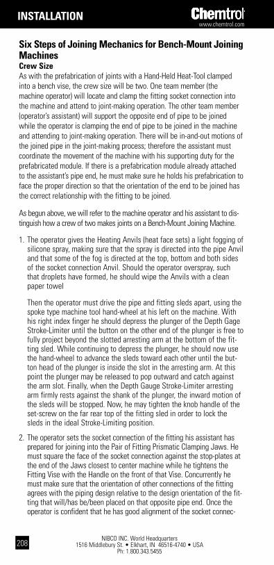
NIBCO INC. World Headquarters 1516 Middlebury St. • Elkhart, IN 46516-4740 • USA
Ph: 1.800.343.5455
www.chemtrol.com
208
six steps of Joining Mechanics for bench-Mount Joining Machinescrew sizeAs with the prefabrication of joints with a Hand-Held Heat-Tool clamped into a bench vise, the crew size will be two. One team member (the machine operator) will locate and clamp the fitting socket connection into the machine and attend to joint-making operation. The other team member (operator’s assistant) will support the opposite end of pipe to be joined while the operator is clamping the end of pipe to be joined in the machine and attending to joint-making operation. There will be in-and-out motions of the joined pipe in the joint-making process; therefore the assistant must coordinate the movement of the machine with his supporting duty for the prefabricated module. If there is a prefabrication module already attached to the assistant’s pipe end, he must make sure he holds his prefabrication to face the proper direction so that the orientation of the end to be joined has the correct relationship with the fitting to be joined. As begun above, we will refer to the machine operator and his assistant to dis-tinguish how a crew of two makes joints on a Bench-Mount Joining Machine.
1. The operator gives the Heating Anvils (heat face sets) a light fogging of silicone spray, making sure that the spray is directed into the pipe Anvil and that some of the fog is directed at the top, bottom and both sides of the socket connection Anvil. Should the operator overspray, such that droplets have formed, he should wipe the Anvils with a clean paper towel
Then the operator must drive the pipe and fitting sleds apart, using the spoke type machine tool hand-wheel at his left on the machine. With his right index finger he should depress the plunger of the Depth Gage Stroke-Limiter until the button on the other end of the plunger is free to fully project beyond the slotted arresting arm at the bottom of the fit-ting sled. While continuing to depress the plunger, he should now use the hand-wheel to advance the sleds toward each other until the but-ton head of the plunger is inside the slot in the arresting arm. At this point the plunger may be released to pop outward and catch against the arm slot. Finally, when the Depth Gauge Stroke-Limiter arresting arm firmly rests against the shank of the plunger, the inward motion of the sleds will be stopped. Now, he may tighten the knob handle of the set-screw on the far rear top of the fitting sled in order to lock the sleds in the ideal Stroke-Limiting position.
2. The operator sets the socket connection of the fitting his assistant has prepared for joining into the Pair of Fitting Prismatic Clamping Jaws. He must square the face of the socket connection against the stop-plates at the end of the Jaws closest to center machine while he tightens the Fitting Vise with the Handle on the front of that Vise. Concurrently he must make sure that the orientation of other connections of the fitting agrees with the piping design relative to the design orientation of the fit-ting that will/has be/been placed on that opposite pipe end. Once the operator is confident that he has good alignment of the socket connec-
installation
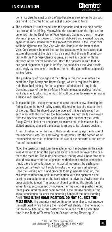
www.chemtrol.com
NIBCO INC. World Headquarters 1516 Middlebury St. • Elkhart, IN 46516-4740 • USA
Ph: 1.800.343.5455209
tion in its Vise, he must cinch the Vise Handle as strongly as he can with one hand, so that the fitting will not slip under joining force.
3. The assistant lifts and maneuvers the opposite end of the pipe he/she has prepared for joining. Meanwhile, the operator sets the pipe end to be joined into the Dual Pair of Pipe Prismatic Clamping Jaws. The oper-ator must place the square cut, beveled, deburred and cleaned pipe end against the radius/chamfer of the socket connection in the Fitting Vice while he tightens the Pipe Vise with the Handle on the front of that Vise. Concurrently, he must instruct his assistant with maneuvers that assure alignment of the pipe in its Vise such that there is 8-point con-tact with the Pipe Vise Clamping Jaws, as well as contact with the entrance of the socket connection. Once the operator is sure that he has good alignment of pipe in its Vise, he must cinch the Vise Handle as strongly as he can with one hand, so that the pipe will not slip under joining force.
The positioning of pipe against the fitting in this step eliminates the need for a Pipe Clamp and Depth Gauge, which is required for Hand-Held Heat-Tool joining. Perfect alignment of pipe and fitting in the Clamping Jaws of the Bench-Mount Machine insures perfect finished joint alignment, which is the most difficult outcome to learn when using a Hand-Held Heat-Tool.
4. To make the joint, the operator must release the set-screw clamping the fitting sled to the travel rod by turning the knob on top of the outer front of the sled. Next, he should back the pipe and fitting sleds away from each other with the machine tool hand-wheel. As both sleds move away from the machine center, the noise made by the plunger of the Depth Gauge Stroke-Limiter may be heard as its nose button is released by the slotted arresting arm and the plunger is sprung to its released position.
After full retraction of the sleds, the operator must grasp the handle of the machine’s Heat-Tool and swing the assembly into the centerline of the machine and rest the handle in the slot of the pedestal at the center front of the machine.
Now, the operator must turn the machine tool hand-wheel in the clock-wise direction to bring the pipe and socket connection toward the cen-ter of the machine. The male and female Heating Anvils (heat face sets) should have nearly perfect alignment with pipe and socket connection. If not, there is some latitude for horizontal movement by pushing or pulling on the Heat-Tool handle to make the necessary adjustment. Once the Heating Anvils and products to be joined are lined up, the assistant continues to work in coordination with the operator as he exerts reasonable force on the hand-wheel to drive the Anvils in/on the products to be joined. The operator should continue the steady hand-wheel force, accompanied by movement of the sleds as plastic melting takes place, until the melt bead, formed in the radius/chamfer of the socket connection, touches the mounting flange of the male Heating Anvil. this is thE hoME position. do not sqUEEZE thE MElt bEad. The operator must continue to remember to not squeeze the melt bead, while holding the Hand-Wheel steady in the home posi-tion to allow heating of the surfaces to be joined for the prescribed time in the Table of Thermo-Fusion Socket Heating Times; pg. 29.
installation

NIBCO INC. World Headquarters 1516 Middlebury St. • Elkhart, IN 46516-4740 • USA
Ph: 1.800.343.5455
www.chemtrol.com
210
note: the dwell time in the home position on the heating anvils at 500° F, for both pp and pVdF in pipe sizes 1⁄2" through 2", is five seconds. this time sequence is so short that it is impractical to reach the home position on these sizes and instantly start the timer to count down five seconds. after minimal practice with a timer or watch, an installer can learn to speak the football quarterback’s cadence of, hut – one, hut – two, hut – three, etc. to count off five seconds even more accurately than moving the hand on command to activate a timer and prop-erly measure the time interval. or, the juvenile cadence of, one-thousand-and-one, one-thousand-and-two, etc. works equally well for others. certainly the cadence count would not be more accurate for 13 seconds or more. we leave it up to you, which method to use, for eight seconds, but by all means, adopt the discipline of using the timer for longer time intervals.
5. As soon as the proper time in the home position has expired, the opera-tor must again coordinate with his assistant to move the heated prod-uct back from the Heating Anvils. The operator does this by quickly turning the Hand-Wheel counterclockwise. As soon as the pipe and fit-ting sleds have been retracted, the operator must quickly lift the Heat-Tool handle and swing it from the machine centerline to its resting place behind the machine.
Now the machine has been cleared for the operator and his assistant to move the pipe sled forward again to make the fusion joint. The operator does this by quickly turning the Hand-Wheel clockwise again. As resis-tance is met from the pipe being inserted into the socket, the operator must never let the forward motion stop. If the motion stops, it can be next to impossible to start again in order to complete the joint. Do not worry though. The force required for pipe insertion is no greater than the force to push the products onto the Heating Anvils. Quickness and steady force are the secrets for success. The machine’s joining stroke will be terminated when the arresting arm on the pipe sled strikes the variable length tube of the Joint Insertion Stroke-Limiter assembly. You will recall that the notch on the tube, corresponding to joint pipe size, was selected in Step 1.
6. Hold the completed joint in the home position for about 10 seconds – a little longer for larger sizes – to permit cooling of the plastic bond. This will prevent the pipe from moving back in the tapered socket while the inner surfaces are fluid. If the operator would prefer to start making preparations for the next joint before cooling is complete, he can again
installation
Polypropylene PVDF Size Time (sec) Temp ° F Temp ° C Size Time (sec) Temp ° F Temp ° C 1/2" 5 495–505 257–263 1/2" 5 495–505 257–263 3/4" 5 495–505 257–263 3/4" 5 495–505 257–263 1" 5 495–505 257–263 1" 5 495–505 257–263 1-1/2" 5 495–505 257–263 1-1/2" 5 495–505 257–263 2" 5 495–505 257–263 2" 5 495–505 257–263 3" 7–9 500–510 260–266 3" 25–35 510–530 266–277 4" 12–15 500–510 260–266 4" 40–50 510–530 266–277 6" 15–20 500–520 260–271 6" 50–60 540–560 282–293Heating times start after pipe and fitting are completely on heater faces (fitting face not to touch base of male heat face).
thermo-Fusion socket heating times

www.chemtrol.com
NIBCO INC. World Headquarters 1516 Middlebury St. • Elkhart, IN 46516-4740 • USA
Ph: 1.800.343.5455211
tighten the Knob of the set-screw, on the far right of the fitting sled, which locks the sleds in place. Just remember to loosen the Knob before resetting the machine for the next joint, as in Step 2.
It is important that the Heating Anvils (heat face sets) be kept as clean
as possible. Any residue left on the Anvils should be removed immedi-ately by wiping with a paper towel. Check the Heat-Tool temperature to make sure that it is stable at the prescribed setting. If residue deposits on the Heating Anvils – following the making of joints – persists, try increasing the silicone spray to thoroughly coat the applicable surfaces and/or reduce the prescribed heating time by increments of 10-20%. Be cautious in the reduction of time for sizes 2" and below. Do not waver from the prescribed temperature settings.
Now that the joint has sufficiently cooled, the operator should remove it from the machine by loosening the Fitting Vise first and then the Pipe Vise.
Flanged Joints
scopeFlanging is used extensively for process lines that require periodic disman-tling. Plastic flanges and factory flanged valves and fittings in PVC, CPVC, PVDF and polypropylene are available in a full range of sizes and types for joining to pipe by solvent welding, threading or socket fusion as in the case with polypropylene and PVDF.
Gasket seals between the flange faces should be an elastomeric full flat faced gasket with a hardness of 50 to 70 durometer A. Chemtrol can pro-vide polychloroprene (CR) gaskets in the 1/2" through 12" range having a 1/8" thickness. For chemical environments too aggressive for polychloro-prene (CR) another resistant elastomer should be used. When it is neces-sary to bolt plastic and metal flanges – use flat face metal flanges – not raised face, and use recommended torques shown in table under ”Installation Tips.“
dimensionsBolt circle and number of bolt holes for the flanges are the same as Class 150 metal flanges per ANSI B16.5. Threads are tapered iron pipe size threads per ANSI B1.20.1. The socket dimensions conform to ASTM D2467 which describes 1/2" through 8" sizes and ASTM D439 for Schedule 80 CPVC which gives dimensional data for 1/2" through 6". Internal Chemtrol specifications have been established for the 10" and 12" PVC patterns and 8" CPVC design, as well as socket designs for polypropylene and PVDF.
pressure RatingAs with all other thermoplastic piping components, the maximum non-shock operating pressure is a function of temperature. Maximum pressure rating for Chemtrol® valves, unions and flanges is 150 psi. Above 100° F refer to the chart on page 13.

NIBCO INC. World Headquarters 1516 Middlebury St. • Elkhart, IN 46516-4740 • USA
Ph: 1.800.343.5455
www.chemtrol.com
212
installation
sealingThe faces of flanges are tapered back away from the orifice area at a 1/2 to 1 degree pitch so that when the bolts are tightened the faces will be pulled together generating a force in the water way area to improve seal-ing.
installation tipsOnce a flange is joined to pipe, the method for joining two flanges together is as follows:
1. Make sure that all the bolt holes of the mating flanges match up. It is not advisable to twist the flange and pipe to achieve this.
2. Use flat washers under bolt heads and nuts.3. Insert all bolts. (Lubricate bolts.)4. Make sure that the faces of the flanges mate snuggly prior to tightening
of the bolts.5. The bolts on the plastic flanges should be tightened by pulling down the
nuts diametrically opposite each other using a torque wrench. (See dia-gram below) Complete tightening should be accomplished in stages. The final torque values are shown in the table below. Uniform stress across the flange will prevent leaky gaskets.
6. If the flange is mated to a rigid and stationary flanged object, or to a metal flange, the adjacent plastic pipe must be supported or anchored to eliminate excessive stress on the flange joint.
Flange Size Recommended Torque* 1/2 - 1 1/2" 10 - 15 ft.Ibs. 2 - 4" 20 - 30 ft.Ibs. 6 - 8" 33 - 50 ft.Ibs. 10" 53 - 75 ft.Ibs. 12" 80 - 110 ft.Ibs.
*For a well lubricated bolt with flat washers under bolt head and nut.
The following tightening pattern is suggested for the flange bolts:

www.chemtrol.com
NIBCO INC. World Headquarters 1516 Middlebury St. • Elkhart, IN 46516-4740 • USA
Ph: 1.800.343.5455213
scopeThe most common method for repairing faulty and leaking joints is hot gas welding at the fillet formed by the fitting socket entrance and the pipe. Fillet welding of thermoplastic is quite similar to the acetylene welding or brazing process used with metals. The fundamental differences are that the plastic rod must always be the same basic material as the pieces to be joined; and heated gas, rather than burning gas, is used to melt the rod and adjacent surfaces.
Welding with plastics involves only surface melting because plastics unlike metals must never be “puddled." Therefore, the resulting weld is not as strong as the parent pipe and fitting material. This being the case, fillet welding as a repair technique is recommended for minor leaks only. It is not recommended as a primary joining technique for pressure rated sys-tems.
welding tools and Materials– Plastic welding gun with pressure regulator, gauge and hose.– Filler rod– Emery cloth– Cotton rags– Cutting pliers– Hand grinder (optional)– Compressed air supply or bottled nitrogen (see Caution next page)– Source of compressed air
weld area preparationWipe all dirt, oil and moisture from the joint area. A very mild solvent may be necessary to remove oil.
caUtion: Make sure that all liquid has been removed from the portion of the piping system where the weld is to be made.
welding Faulty Joints1. Remove residual solvent cement from the
weld area using emery cloth. When weld-ing threaded joints, a file can be used to remove threads in the weld area.
2. Wipe the weld area clean of dust, dirt and moisture.
Repairing Thermoplastic Pipe Joints
installation
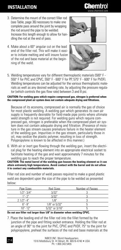
NIBCO INC. World Headquarters 1516 Middlebury St. • Elkhart, IN 46516-4740 • USA
Ph: 1.800.343.5455
www.chemtrol.com
214
3. Determine the mount of the correct filler rod (see Table, page 36) necessary to make one complete pass around the joint by wrapping the rod around the pipe to be welded. Increase this length enough to allow for han-dling the rod at the end of pass.
4. Make about a 60° angular cut on the lead end of the filler rod. This will make it easi-er to initiate melting and will insure fusion of the rod and base material at the begin-ning of the weld.
5. Welding temperatures vary for different thermoplastic materials (500° F - 550° F for PVC and CPVC, 550° F - 600° F for PP, 575° F - 600° F for PVDF). Welding temperatures can be adjusted for the various thermoplastic mate-rials as well as any desired welding rate, by adjusting the pressure regula-tor (which controls the gas flow rate) between 3 and 8 psi.
caUtion: For welding guns which require compressed gas, nitrogen is preferred when the compressed plant air system does not contain adequate drying and filtrations.
Because of its economy, compressed air is normally the gas of choice for most plastic welding. A welding gun which generates its own air supply is frequently desirable for field-made pipe joints where ultimate weld strength is not required. For welding guns which require com-pressed gas, nitrogen is preferable when the compressed plant air sys-tem does not contain adequate drying and filtration. (Presence of mois-ture in the gas stream causes premature failure in the heater element of the welding gun. Impurities in the gas stream, particularly those in oil, may oxidize the plastic polymer, resulting in loss of strength. Polypropylene is known to be affected in this manner.)
6. With air or inert gas flowing through the welding gun, insert the electri-cal plug for the heating element into an appropriate electrical socket to facilitate heating of the gas and wait approximately 7 minutes for the welding gas to reach the proper temperature.
caUtion: the metal barrel of the welding gun houses the heating element so it can attain extremely high temperatures. avoid contact with the barrel and do not allow it to contact any combustible materials.
Filler rod size and number of weld passes required to make a good plastic weld are dependent upon the size of the pipe to be welded as presented below:
Pipe Sizes Rod Sizes Number of Passes 1/2" - 3/4" 3/32" 3 1" - 2" 3/32" 3 2 1/2" - 4" 1/8" 3 6" - 8" 1/8" or 5/32" 5 10" - 12" 5/32" or 3/16" 5do not use filler rod larger than 1/8" in diameter when welding cpVc.
7. Place the leading end of the filler rod into the fillet formed by the junction of the pipe and fitting socket entrance. Holding the filler rod at an angle of 90° to the joint for PVC, CPVC and PVDF, 75° to the joint for polypropylene, preheat the surfaces of the rod and base materials at the
installation
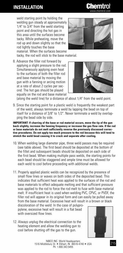
www.chemtrol.com
NIBCO INC. World Headquarters 1516 Middlebury St. • Elkhart, IN 46516-4740 • USA
Ph: 1.800.343.5455215
weld starting point by holding the welding gun steady at approximately 1/4" to 3/4" from the weld starting point and directing the hot gas in this area until the surfaces become tacky. While preheating, move the rod up and down slightly so that the rod lightly touches the base material. When the surfaces become tacky, the rod will stick to the base material.
8. Advance the filler rod forward by applying a slight pressure to the rod. Simultaneously applying even heat to the surfaces of both the filler rod and base material by moving the gun with a fanning or arcing motion at a rate of about 2 cycles per sec-ond. The hot gas should be played equally on the rod and base material (along the weld line) for a distance of about 1/4" from the weld point.
9. Since the starting point for a plastic weld is frequently the weakest part of the weld, always terminate a weld by lapping the bead on top of itself for a distance of 3/8" to 1/2". Never terminate a weld by overlap-ping the bead side by side.
iMpoRtant: if charring of the base or rod material occurs, move the tip of the gun back slightly, increase the fanning frequency or increase the gas flow rate. if the rod or base materials do not melt sufficiently reverse the previously discussed correc-tive procedures. do not apply too much pressure to the rod because this will tend to stretch the weld bead causing it to crack and separate after cooling.
10. When welding large diameter pipe, three weld passes may be required (see table above). The first bead should be deposited at the bottom of the fillet and subsequent beads should be deposited on each side of the first bead. When making multiple pass welds, the starting points for each bead should be staggered and ample time must be allowed for each weld to cool before proceeding with additional welds.
11. Properly applied plastic welds can be recognized by the presence of small flow lines or waves on both sides of the deposited bead. This indicates that sufficient heat was applied to the surfaces of the rod and base materials to effect adequate melting and that sufficient pressure was applied to the rod to force the rod melt to fuse with base material melt. If insufficient heat is used when welding PVC, CPVC, or PVDF, the filler rod will appear in its original form and can easily be pulled away from the base material. Excessive heat will result in a brown or black discoloration of the weld. In the case of polypro-pylene, excessive heat will result in a flat bead with oversized flow lines.
12. Always unplug the electrical connection to the heating element and allow the welding gun to cool before shutting off the gas to the gun.
installation

NIBCO INC. World Headquarters 1516 Middlebury St. • Elkhart, IN 46516-4740 • USA
Ph: 1.800.343.5455
www.chemtrol.com
216
welding principlesThe procedures for making good thermoplastic welds can be summarized
into four basic essentials:• Correct Heating - Excessive heating will char or overmelt. Insufficient
heating will result in incomplete melting.• Correct Pressure - Excessive pressure can result in stress cracking when
the weld cools. Insufficient pressure will result in incomplete fusion of the rod material with the base material.
• Correct Angle - Incorrect rod angle during welding will stretch the rod and the rod material with the base material.
• Correct Speed - Excessive welding speed will stretch the weld bead and the finished weld will crack upon cooling.
installation
threading and Joining1. Hold pipe firmly in a pipe vise. Protect the pipe at the point of grip by
inserting a rubber sheet or other material between the pipe and vise.
2. A tapered plug must be inserted in the end of the pipe to be threaded. This plug provides additional support and prevents distortion of the pipe in the threaded area. Distortion of the pipe during the threading opera-tion will result in eccentric threads, non-uniform circumferential thread depth or gouging and tearing of the pipe wall. See the following Table for approximate plug O.D. dimensions.
table: Reinforcing plug dimensions* Pipe Size Plug O.D. 1/2" .526 3/4" .722 1" .935 1 1/4" 1.254 1 1/2" 1.476 2" 1.913 2 1/2" 2.289 3" 2.864 4" 3.786*These dimensions are based on the median wall thicknesses and average outside diameter for the respective pipe sizes. Variations in wall thicknesses and O.D. dimensions may require alteration of the plug dimensions.
3. Use a die stock with a proper guide that is free of burrs or sharp edges, so the die will start and go on square to the pipe axis.
4. Push straight down on the handle, avoiding side pressure that might dis-tort the sides of the threads. If power threading equipment is used, the dies should not be driven at high speeds or with heavy pressure. Apply an external lubricant liberally when cutting the threads. Advance the die until the trailing end of the cutting chases approximately pass the end of the pipe.
do not threAd schedule 40 pipe
Threading Instructions for Thermoplastic Pipe
www.chemtrol.com
NIBCO INC. World Headquarters 1516 Middlebury St. • Elkhart, IN 46516-4740 • USA
Ph: 1.800.343.5455217
Do not overthread because all threads between the end of the pipe and the trailing end of the chases will be straight and not tapered as indicated in the sketch above.
5. Periodically check the threads with a ring gauge to ensure that proper procedures are being followed. The gauging tolerance is ± 1 1/2 turns and diametrical adjustment to the cutting chases within the die may be required.
6. Brush threads clean of chips and ribbons. Then starting with the second full thread tape in the direction of the threads. Overlap each wrap by one half the width of the tape. NIBCO does not recommend the use of any thread lubricant/sealant other than PTFE tape.
7. Thread the fitting onto the pipe and tighten by hand. Using a strap wrench only, further tighten the connection an additional one to two threads past hand tightness. Avoid excessive torque as this may cause thread damage or fitting damage.
pressure testingThreaded piping systems can be pressure tested up to 100% of the hydro-static pressure rating as soon as the last connection is made.
caUtion: air or compressed gas is not recommended and should not be used as a media for pressure testing of plastic piping systems.
The installation instructions contained herein are recommendations. It is the respon-sibility of the installer to follow industry best practices for installation and to comply with all applicable codes and regulations.
installation
NIBCO INC. World Headquarters 1516 Middlebury St. • Elkhart, IN 46516-4740 • USA
Ph: 1.800.343.5455
www.chemtrol.com
218
The presence of Ultraviolet (UV) must at least be considered for every material because of the effect of its radiation of pipe on the medium car-ried within the pipe depends upon the basic material as well as the pig-mentation (colorant) package in the material.
PVC and CPVCBoth materials are attacked by UV radiation, resulting in degradation of the polymeric chains. Embrittlement is the first sign of deterioration, followed by loss of strength and general deterioration of all other physical proper-ties. Industrial CPVC Sch. 80 piping components are traditionally colored light gray while PVC products are dark gray. The coloration for both sys-tems of products is achieved by a blend of Titanium Dioxide (white) and Carbon Black (black). In order to maintain a consistent tone of color, a pig-mentation package of approximately 2.5% by weight is required. Through many years of experience it has been shown that the irradiation is blocked by pigment at the surface. B. F. Goodrich conducted one controlled experi-ment of PVC cooling tower piping on the roof of a motel in Orlando, Florida for over 30 years. Typically, after several years’ exposure the gray color, particularly on the pipe top that bears the brunt from the sun, washed out to a lighter gray with white showing through. But when the surface was scratched with the edge of a knife blade the rich dark gray was present, indicating that radiation had not penetrated below the surface. Samples of pipe were taken from the installation at five-year intervals so that coupons could be extracted for physical property testing. After 30 years the testing was stopped with the conclusion that 25 years service could be expected because no statistical difference in results had been noted. Although in most applications involving schedule 80 gray piping, painting or covering the system to prevent exposure to UV radiation may not be a necessity, in instances where such systems may be routinely or continuously exposed to degradation due to environmental conditions, supplementary protection may be recommended. Consult NIBCO Technical Services with questions in such applications.
PVC Sch 40 and SDR water and sewer piping, which are traditionally white in color, may be another story. There is no requirement for the amount of Titanium Dioxide to be included in the plastic compound for white color-ation. As a result, minimal amounts of pigment may be present in these very cost competitive high volume products, and the commercial white pip-ing products should be suspect under long-term direct exposure to sun without some UV protection, painting being one option.PolypropyleneAll polyolefins are severely degraded by UV radiation. However, the black PP used in Chemtrol products is formulated with a minimum of 2.5% car-bon black being suitable for long-term outdoor service.
Ultraviolet Radiation of Thermoplastic Piping Materials
installation

www.chemtrol.com
NIBCO INC. World Headquarters 1516 Middlebury St. • Elkhart, IN 46516-4740 • USA
Ph: 1.800.343.5455219
PVDF (Kynar®)PVDF, absent of any color pigment, is transparent to UV, so it is not degrad-ed by sunlight. Direct sunlight can frequently adversely affect the fluid medium stability; therefore, Chemtrol PVDF piping is available with an FDA-approved red pigment.
PaintingAlthough the slick hard surfaces of the thermoplastic piping systems listed above are not ideal for paint adhesion they may be effectively painted for facilities color coding, cosmetic enhancement or added UV protection. The paint should be a water-based 100% acrylic emulsion system for exterior use. The system will include a primer coat and one topcoat. If the reason for painting is to provide UV protection, white or another light color is the best choice. These contain a greater amount of pigment, principally Titanium Dioxide. Use any brand of high quality house or industrial paint because these have the higher concentration of pigment and it is the pig-ment that provides the UV protection. There are two hints, which will greatly contribute to adhesion. First, wash the entire exterior with solvent to clean and degrease it. Axial-grease and caked mud are obvious, but small particles of sand, dust, printing and body oil (fingerprints) are less obvious impurities that require removal. Therefore, do not get the cleaning process too far ahead of painting. Use Methyl Ethyl Ketone (MEK) (avail-able as a plastic pipe cleaner from many distributors of industrial plastic piping) or Isopropyl Alcohol, although more elbow grease will be required with the later. Do not overlook the need for good ventilation when using solvents. Second, insure a continuous film of paint over the entire piping surface. The cohesion of the paint films themselves will help the coating to adhere to the piping. It becomes apparent that painting is not an inexpen-sive addition to the piping system. However, to specify it correctly the first time will reduce maintenance costs in the long run.
Kynar® is a registered trademark of Arkema Inc.
The general installation procedures detailed here apply to polyvinyl chlo-ride (PVC) and chlorinated polyvinyl chloride (CPVC) pressure pipe that has solvent welded joints up through 8" in size. These procedures are applica-ble for all liquids that are conveyed at pressures up to the maximum hydro-static pressure rating of the pipe or of any component in the piping system, whichever is lowest.
Chemtrol Technical Services should be consulted for installation guidance and recommendation on all sizes of pipe 10" and above and where the installer has had no experience in the installation of PVC or CPVC piping. For additional information, refer to ASTM D2774, “Underground Installation of Thermoplastic Pressure Piping."
General Underground Installation Procedures for PVC and CPVC Solvent Welded Pipe
installation

NIBCO INC. World Headquarters 1516 Middlebury St. • Elkhart, IN 46516-4740 • USA
Ph: 1.800.343.5455
www.chemtrol.com
220
inspectionBefore installation, all lengths of PVC or CPVC pipe and fittings should be thoroughly inspected for cuts, scratches, gouges, buckling, kinking and any other imperfections (such as splits on I.D. or ends of pipe due to impact) which may have been imparted to the pipe during shipping, unloading, stor-ing and stringing. Any pipe or precoupled fittings containing harmful or even questionable defects should be removed by cutting out the damaged section as a complete cylinder.
trenchingThe trench should be of adequate width to allow convenient installation of PVC or CPVC pipe, at the same time being as narrow as possible. The fol-lowing trench sizes have been used with success. However, actual sizes may vary with terrain and specific application.
Minimum trench widths may be utilized by joining pipe outside of the trench and lowering it into the trench after adequate joint strength has been obtained. Trench widths will have to be wider where the pipe is joined in the trench, or where thermal expansion and contraction is a fac-tor. See section titled “Snaking of Pipe." Light Traffic Heavy Traffic Ground Cover Ground Cover Pipe Size Trench Width Minimum Minimum 3" & Under 8" 12" - 18" 24" - 30" 4" & 6" 12" 18" - 24" 30" - 36" 8" 16" 24" - 30" 36" - 42"
The trench bottoms should be continuous, relatively smooth and free of rocks. Where ledge rock, hardpan or boulders are encountered, it is advis-able to pad the trench bottom using a minimum of four (4) inches of tamped earth or sand beneath the pipe as a cushion and for protection of the pipe from damage.
Sufficient cover must be maintained to keep external stress levels below acceptable design stress. Reliability and safety of service may assume major importance in determining minimum cover. Local, state and national codes may also govern.
Pipe intended for water service should be buried at least 12" below the maximum expected frost penetration.
size of Joining crewField practice has shown that the size of the joining crew will depend upon a number of variables, such as, size and length of the pipe, the atmospher-ic temperature, construction conditions, construction time element, amount of pipe to be layed, construction workers’ experience in laying PVC or CPVC pipe, etc. Although it is possible for one man to join the smaller sizes of pipe (2" and under) by himself, it is not necessarily practical to do so. Therefore, the crew sizes presented here are intended as a guide for those PVC or CPVC pipe users who have not had a great deal of experience in the installation of such buried pipe:
installation
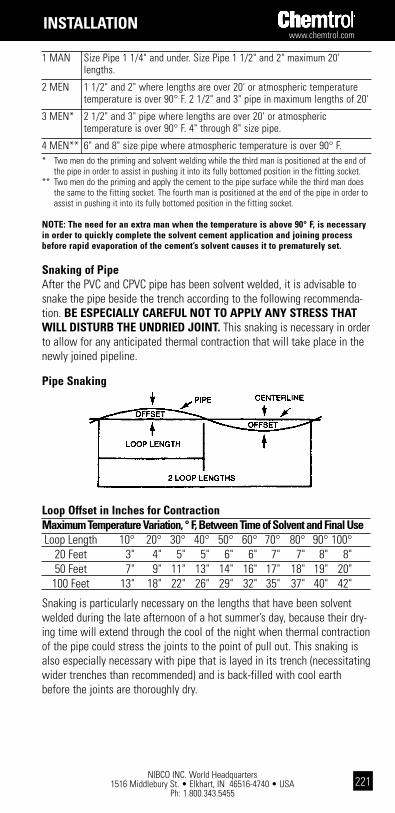
www.chemtrol.com
NIBCO INC. World Headquarters 1516 Middlebury St. • Elkhart, IN 46516-4740 • USA
Ph: 1.800.343.5455221
1 MAN Size Pipe 1 1/4" and under. Size Pipe 1 1/2" and 2" maximum 20' lengths.
2 MEN 1 1/2" and 2" where lengths are over 20' or atmospheric temperature temperature is over 90° F. 2 1/2" and 3" pipe in maximum lengths of 20'
3 MEN* 2 1/2" and 3" pipe where lengths are over 20' or atmospheric temperature is over 90° F. 4" through 8" size pipe.
4 MEN** 6" and 8" size pipe where atmospheric temperature is over 90° F.* Two men do the priming and solvent welding while the third man is positioned at the end of
the pipe in order to assist in pushing it into its fully bottomed position in the fitting socket.** Two men do the priming and apply the cement to the pipe surface while the third man does
the same to the fitting socket. The fourth man is positioned at the end of the pipe in order to assist in pushing it into its fully bottomed position in the fitting socket.
notE: the need for an extra man when the temperature is above 90° F, is necessary in order to quickly complete the solvent cement application and joining process before rapid evaporation of the cement’s solvent causes it to prematurely set.
snaking of pipe After the PVC and CPVC pipe has been solvent welded, it is advisable to snake the pipe beside the trench according to the following recommenda-tion. bE EspEciallY caREFUl not to applY anY stREss that will distURb thE UndRiEd Joint. This snaking is necessary in order to allow for any anticipated thermal contraction that will take place in the newly joined pipeline.
pipe snaking
loop offset in inches for contractionMaximum temperature Variation, ° F, between time of solvent and Final Use Loop Length 10° 20° 30° 40° 50° 60° 70° 80° 90° 100° 20 Feet 3" 4" 5" 5" 6" 6" 7" 7" 8" 8" 50 Feet 7" 9" 11" 13" 14" 16" 17" 18" 19" 20" 100 Feet 13" 18" 22" 26" 29" 32" 35" 37" 40" 42"
Snaking is particularly necessary on the lengths that have been solvent welded during the late afternoon of a hot summer’s day, because their dry-ing time will extend through the cool of the night when thermal contraction of the pipe could stress the joints to the point of pull out. This snaking is also especially necessary with pipe that is layed in its trench (necessitating wider trenches than recommended) and is back-filled with cool earth before the joints are thoroughly dry.
installation

NIBCO INC. World Headquarters 1516 Middlebury St. • Elkhart, IN 46516-4740 • USA
Ph: 1.800.343.5455
www.chemtrol.com
222
bending of plastic pipeWhenever a change of direction is required in a pipeline, it is best accom-plished using straight lengths of pipe and factory-made fittings. Bending of pipe leaves residual stresses and consequently bending is not recommend-ed as a normal practice, particularly if the line is intended to operate at or near maximum temperatures and/or pressure. If field bending is required to meet special conditions the following tech-niques should be employed to give the best pressure carrying capability of the installed system.
1. Heating Media: The heating media may be hot air in a circulating oven operating at approximately 360° F. The heating media may also be radi-ant heat in which case the pipe surface in the area of the bend or the pipe may be immersed in hot oil. An open flame should never be used. Heating times will range from approximately one to five minutes or until it becomes soft and pliable to bend, depending upon pipe size and type of heat source.
2. To maintain the cross sectional area of the I.D. of the pipe in the area of the bend, it must be supported during the bending operations.
There are three suggested methods for supporting the pipe.a. The I.D. can be supported by filling with preheated sand and plug-
ging both ends.b. A heated reinforcing spring can be placed inside of the pipe after it
has been heated to a soft, pliable condition. The spring should be made with 3/32" diameter wire and the O.D. of the spring should be slightly less than the nominal I.D. of the pipe to be bent. Springs can be custom made by any local spring manufacturer.
c. When the pipe becomes soft and pliable it can be placed in forming jig or form and bent as quickly as possible to prevent weakening or deforming of the pipe.
3. The minimum radius to which a bend should be made, measured from the inner edge of the curve, should be 8 pipe diameter for 3/4" pipe size and below and 6 pipe diameters for larger pipe. The initial forming bend will have to be slightly greater to allow for spring back.
4. The bend should be kept in the bent form until the pipe cools and becomes rigid enough to be handled without deforming. It should then be immediately immersed in water to complete the cooling process. The sand or spring should not be removed until final cooling is completed.
When plastic pipe is heated and then bent, it will shrink with the degree of shrinkage depending on the size of the pipe and the radius of the bend. Therefore, the pipe should be cut to lengths slightly greater than the total length of the bend and the tangents.
5. A straight section of at least two pipe diameters should be left at either side of the bend to insure a round, low stress section with which to make joints.
notE: highly crystalline thermoplastics such as pVdF should never be formed in this way due to the potential detrimental effect of the process on the molecular structure and properties of the material.
The above discussion covers only the basics involved with bending plastic pipe. Experience and some trial-and-error will be required to develop an expertise in bending pipe. Contact the pipe manufacturer with further questions.
installation

www.chemtrol.com
NIBCO INC. World Headquarters 1516 Middlebury St. • Elkhart, IN 46516-4740 • USA
Ph: 1.800.343.5455223
cleaningEven though care should be exercised at all times to prevent the entry of dirt, water, and other foreign material into the PVC or CPVC pipe fittings, it is advisable that the pipeline be thoroughly cleaned before working pressure is applied.
backfillingIdeally, backfilling should only be done early in the morning during hot weather when the line is fully contracted and there is no chance of insuffi-ciently dried joints being subject to contraction stresses.
The pipe should be uniformly and continuously supported over its entire length on firm, stable material. Blocking should not be used to change pipe grade or to intermittently support pipe across excavated sections.
Pipe is installed in a wide range of sub-soils. These soils should not only be stable but applied in such a manner so as to physically shield the pipe from damage. Attention should be given to local pipe laying experience which may indicate particular pipe bedding problems.
Backfill materials free of rocks with a particle size of 1/2" or less should be used to surround the pipe with 6" to 8" of cover. It should be placed in layers. Each solid layer should be sufficiently compacted to uniformly develop lateral passive soil forces during the backfill operation. It may be advisable to have the pipe under pressure, 15 to 25 psi during the backfill-ing.
Effects of ground freezing should be considered when pipe is installed at depths subject to frost penetration.
Vibratory methods are preferred when compacting sand or gravels. Best results are obtained when the soils are in nearly saturated condition. Where water flooding is used, the initial backfill should be sufficient to insure complete coverage of the pipe. Additional material should not be added until the water flooded backfill is firm enough to walk on. Care should be taken to avoid floating the pipe.
Sand and gravel containing a significant proportion of fine-grained materi-al, such as silt and clay, should be compacted by hand or, preferably by mechanical tamper.The remainder of the backfill should be placed and spread in approximately uniform layers in such a manner to fill the trench completely so that there will be no unfilled spaces under or about rocks or lumps of earth in the backfill. Large or sharp rocks, frozen clods and other debris greater than 3" in diameter should be removed. Rolling equipment or heavy tampers should only be used to consolidate the final backfill.
Additional information on underground installation is given in ASTM D2321 ”Underground Installation of Flexible Thermoplastic Pressure Piping.“
connecting pipe sectionsSections of PVC or CPVC pipe that have been backfilled or plowed in during the heat of the day should be sufficiently overlapped to allow for contrac-tion and not joined up to one another or any stable connection or fitting until the morning following their night of cooling and thermal contraction.
installation

NIBCO INC. World Headquarters 1516 Middlebury St. • Elkhart, IN 46516-4740 • USA
Ph: 1.800.343.5455
www.chemtrol.com
224
See the section “Expansion and Thermal Contraction of Plastic Pipe" page 18 for calculating anticipated contraction.
pipe locatingThe location of all PVC and CPVC pipelines should be accurately and pre-cisely recorded. Conductive wire can be trenched or plowed in with the pipe as an aid for future locating purposes.
below grade Valves, anchors or other connectionsAs a rule of thumb in designing and installing a PVC or CPVC underground piping system, it is pointed out that pipe made from these materials is not designed to be used for any structural applications beyond withstanding normal soil loads and internal pressures up to its hydrostatic pressure rat-ing.
Anchors, valve boxes, etc. must be independently supported so as to not introduce additional bending or sheer stress on the pipe.
Roadways and Railroad tracksIt is recommended that plastic pipe be run within a metal or concrete cas-ing when it is installed beneath surfaces that are subject to heavyweight or constant traffic; such as roadways, railroad tracks, etc.
concrete anchorsConcrete anchors can be poured around PVC or CPVC pipe at direction changes. If the purpose for anchoring is to restrain axial movement of the pipe, this can be done by solvent welding split collars around the pipe O.D. to provide a shoulder against the concrete wall. Solvent welded surface between collar and pipe O.D. must dry 48 hours prior to pouring of con-crete.
RisersAlthough PVC or CPVC pipe has excellent weathering resistance, it should not be brought above grade under the following circumstances:
1. If it is expected to provide structural strength, such as supporting an above-grade metal valve. The metal valve should be installed with an independent support.
2. If it is subject to external damage. This could be remedied by sleeving the pipe with an independently and rigidly supported steel pipe.
3. If it is subject to high temperature environments; i.e. summer sun that could lower the pipe's pressure rating below an acceptable level. Such a situation might be remedied by insulating the PVC or CPVC pipe.
The installation instructions contained herein are recommendations. It is the responsibility of the installer to follow industry best practices for installation and to comply with all applicable codes and regulations.
installation

www.chemtrol.com
NIBCO INC. World Headquarters 1516 Middlebury St. • Elkhart, IN 46516-4740 • USA
Ph: 1.800.343.5455225
REFEREncE data
linear conversion table From Fractional inches to Millimeters
inches mm inches mm1/64 .016 .397 33/64 .516 13.0971/32 .031 .794 17/32 .531 13.4943/64 .047 1.191 35/64 .547 13.8911/16 .063 1.588 9/16 .563 14.2885/64 .078 1.984 37/64 .578 14.6843/32 .094 2.381 19/32 .594 15.0817/64 .109 2.778 39/64 .609 15.4781/8 .125 3.175 5/8 .625 15.875
9/64 .141 3.572 41/64 .641 16.2725/32 .156 3.969 21/32 .656 16.669
11/64 .172 4.366 43/64 .672 17.0663/16 .188 4.763 11/16 .688 17.463
13/64 .203 5.519 45/64 .703 17.8597/32 .219 5.556 23/32 .719 18.256
15/64 .234 5.953 47/64 .734 18.6531/4 .250 6.350 3/4 .750 19.050
17/64 .266 6.747 49/64 .766 19.4479/32 .281 7.144 25/32 .781 19.844
19/64 .297 7.541 51/64 .797 20.2415/16 .313 7.938 13/16 .813 20.638
21/64 .328 8.334 53/64 .828 21.03411/32 .344 8.731 27/32 .844 21.43123/64 .359 9.128 55/64 .859 21.8283/8 .375 9.525 7/8 .875 22.225
25/64 .391 9.922 57/64 .891 22.62213/32 .406 10.319 29/32 .906 23.01927/64 .422 10.716 59/64 .922 23.4167/16 .438 11.113 15/16 .938 23.813
29/64 .453 11.509 61/64 .953 24.20915/32 .469 11.906 31/32 .969 24.60631/64 .484 12.303 63/64 .984 25.0031/2 .500 12.700 1 1.000 25.400
Metric Equivalent Charts
temperatureconversionF = C x 1.8 + 32C= (F-32) ÷ 1.8
* For
mer
ly k
now
n as
Cen
tigra
de.
Units Change to Multiply byInches Millimeters 25.4Inches Centimeters 2.54Inches Meters 0.0254Feet Meters 0.3048
Miles Kilometers 1.609347Sq. Inches Sq. Centimeters 6.452Sq. Feet Sq. Meters 0.0929
Cu. Inches Cu. Centimeters 16.3872Cu. Feet Cu. Meters 0.02832
U.S. Gallons Liters 3.7854Pounds Kilograms 0.45359
English to Metric conversion table
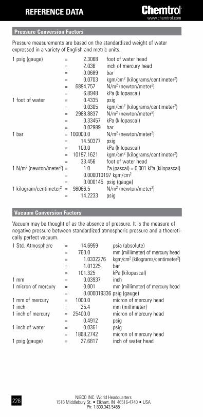
NIBCO INC. World Headquarters 1516 Middlebury St. • Elkhart, IN 46516-4740 • USA
Ph: 1.800.343.5455
www.chemtrol.com
226
REFEREncE data
pressure conversion Factors
Pressure measurements are based on the standardized weight of water expressed in a variety of English and metric units.
1 psig (gauge) = 2.3068 foot of water head = 2.036 inch of mercury head = 0.0689 bar = 0.0703 kgm/cm2 (kilograms/centimeter2) = 6894.757 N/m2 (newton/meter2) = 6.8948 kPa (kilopascal)1 foot of water = 0.4335 psig = 0.0305 kgm/cm2 (kilograms/centimeter2) = 2988.8837 N/m2 (newton/meter2) = 0.33457 kPa (kilopascal) = 0.02989 bar1 bar = 100000.0 N/m2 (newton/meter2) = 14.50377 psig = 100.0 kPa (kilopascal) = 10197.1621 kgm/cm2 (kilograms/centimeter2) = 33.456 foot of water head1 N/m2 (newton/meter2) = 1.0 Pa (pascal) = 0.001 kPa (kilopascal) = 0.000010197 kgm/cm2
= 0.000145 psig (gauge)1 kilogram/centimeter2 = 98066.5 N/m2 (newton/meter2) = 14.2233 psig
Vacuum conversion Factors
Vacuum may be thought of as the absence of pressure. It is the measure of negative pressure between standardized atmospheric pressure and a theoreti-cally perfect vacuum.1 Std. Atmosphere = 14.6959 psia (absolute) = 760.0 mm (millimeter) of mercury head = 1.0332276 kgm/cm2 (kilograms/centimeter2) = 1.01325 bar = 101.325 kPa (kilopascal)1 mm = 0.03937 inch1 micron of mercury = 0.001 mm (millimeter) of mercury head = 0.000019336 psig (gauge)1 mm of mercury = 1000.0 micron of mercury head1 inch = 25.4 mm (millimeter)1 inch of mercury = 25400.0 micron of mercury head = 0.4912 psig1 inch of water = 0.0361 psig = 1868.2742 micron of mercury head1 psig (gauge) = 27.6817 inch of water head
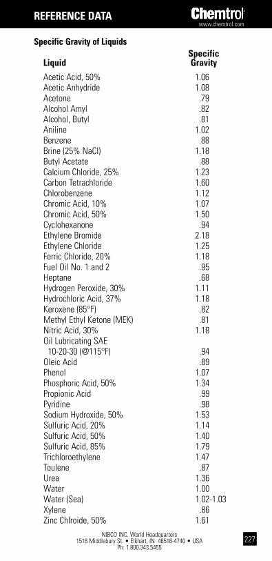
www.chemtrol.com
NIBCO INC. World Headquarters 1516 Middlebury St. • Elkhart, IN 46516-4740 • USA
Ph: 1.800.343.5455227
specific gravity of liquids specific liquid gravity
Acetic Acid, 50% 1.06 Acetic Anhydride 1.08 Acetone .79 Alcohol Amyl .82 Alcohol, Butyl .81 Aniline 1.02 Benzene .88 Brine (25% NaCI) 1.18 Butyl Acetate .88 Calcium Chloride, 25% 1.23 Carbon Tetrachloride 1.60 Chlorobenzene 1.12 Chromic Acid, 10% 1.07 Chromic Acid, 50% 1.50 Cyclohexanone .94 Ethylene Bromide 2.18 Ethylene Chloride 1.25 Ferric Chloride, 20% 1.18 Fuel Oil No. 1 and 2 .95 Heptane .68 Hydrogen Peroxide, 30% 1.11 Hydrochloric Acid, 37% 1.18 Keroxene (85°F) .82 Methyl Ethyl Ketone (MEK) .81 Nitric Acid, 30% 1.18 Oil Lubricating SAE 10-20-30 (@115°F) .94 Oleic Acid .89 Phenol 1.07 Phosphoric Acid, 50% 1.34 Propionic Acid .99 Pyridine .98 Sodium Hydroxide, 50% 1.53 Sulfuric Acid, 20% 1.14 Sulfuric Acid, 50% 1.40 Sulfuric Acid, 85% 1.79 Trichloroethylene 1.47 Toulene .87 Urea 1.36 Water 1.00 Water (Sea) 1.02-1.03 Xylene .86 Zinc Chlroide, 50% 1.61
REFEREncE data

NIBCO INC. World Headquarters 1516 Middlebury St. • Elkhart, IN 46516-4740 • USA
Ph: 1.800.343.5455
www.chemtrol.com
228
drill sizes for pipe taps size of number diam. size of number diam. tap in of threads of tap in of threads of inches per inch drill inches per inch drill
1/8 27 11/32 2 111/2 23/16 1/4 18 7/16 21/2 8 25/8 3/8 18 37/64 3 8 31/4 1/2 14 23/32 31/2 8 33/4 3/4 14 59/64 4 8 41/4 1 111/2 15/32 41/2 8 43/4 11/4 111/2 11/2 5 8 55/16 11/2 111/2 123/32 6 8 63/8
tap and drill sizes (american standard coarse)
size of size of threads size of size of threads drill tap per inch drill tap per inch
7 1/4 20 49/64 7/8 9 F 5/16 18 53/64 15/16 9 5/16 3/8 16 7/8 1 8 U 7/16 14 63/64 11/8 7 27/64 1/2 13 17/64 11/4 7
31/64 9/16 12 17/32 13/8 6 17/32 5/8 11 111/32 11/2 6 19/32 11/16 11 129/64 15/8 51/2 21/32 3/4 10 111/16 13/4 5 23/32 13/16 10 19/16 17/8 5 125/32 2 41/2
REFEREncE data
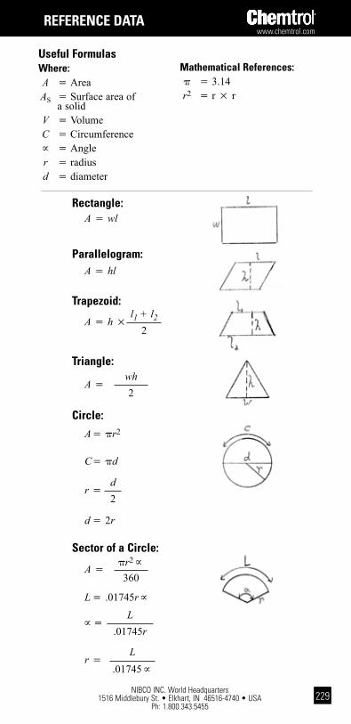
www.chemtrol.com
NIBCO INC. World Headquarters 1516 Middlebury St. • Elkhart, IN 46516-4740 • USA
Ph: 1.800.343.5455229
REFEREncE data
Useful Formulaswhere: A 5 Area AS 5 Surface area of a solid V 5 Volume C 5 Circumference; 5 Angle r 5 radius d 5 diameter
Mathematical References:p 5 3.14 r2 5 r 3 r
trapezoid:
A 5 h 3l1 + l2
2
triangle:
A 5wh2
circle:A 5pr2
C 5pd
r 5d2
d 52r
parallelogram:A 5 hl
Rectangle:A5 wl
sector of a circle:
L 5.01745r;
; 5L
.01745r
A 5pr2;
360
r 5L
.01745;
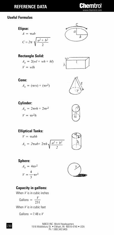
NIBCO INC. World Headquarters 1516 Middlebury St. • Elkhart, IN 46516-4740 • USA
Ph: 1.800.343.5455
www.chemtrol.com
230
REFEREncE data
Elipse:A5 pab
Useful Formulas
C 2p a2 + b2
2
Rectangle solid:As 5 2(wl + wh + hl)
V 5 wlh
cone:As 5 (prs) + (pr2)
cylinder:As 5 2prh + 2pr2
V 5 pr2h
Elliptical tanks:V 5 pabh
As 5 2pab+ 2ph a2 + b2
2
sphere:As 5 4pr2
43
V 5 pr3
capacity in gallons:When V is in cubic inches
When V is in cubic feet
V231
Gallons 5
Gallons 57.48 x V
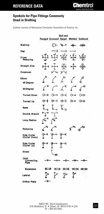
www.chemtrol.com
NIBCO INC. World Headquarters 1516 Middlebury St. • Elkhart, IN 46516-4740 • USA
Ph: 1.800.343.5455231
symbols for pipe Fittings commonly Used in drafting
Symbols courtesy of Mechanical Contractors Association of America, Inc.
bell and Flanged screwed spigot welded soldered
REFEREncE data
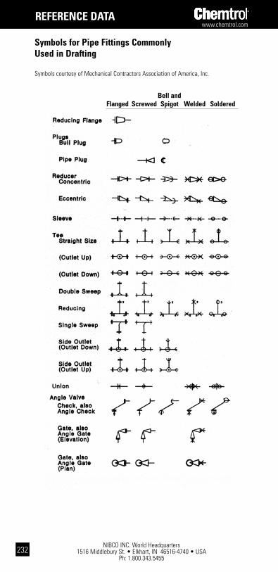
NIBCO INC. World Headquarters 1516 Middlebury St. • Elkhart, IN 46516-4740 • USA
Ph: 1.800.343.5455
www.chemtrol.com
232
symbols for pipe Fittings commonly Used in drafting
Symbols courtesy of Mechanical Contractors Association of America, Inc.
bell and Flanged screwed spigot welded soldered
REFEREncE data

www.chemtrol.com
NIBCO INC. World Headquarters 1516 Middlebury St. • Elkhart, IN 46516-4740 • USA
Ph: 1.800.343.5455233
symbols for pipe Fittings commonly Used in drafting
Symbols courtesy of Mechanical Contractors Association of America, Inc.
bell and Flanged screwed spigot welded soldered
REFEREncE data

NIBCO INC. World Headquarters 1516 Middlebury St. • Elkhart, IN 46516-4740 • USA
Ph: 1.800.343.5455
www.chemtrol.com
234
abbreviations ansi — American National Standards Institute astM — American Society for Testing and Materials cpVc — Chlorinated Poly (Vinyl Chloride) plastic or resin iapMo — International Association of Plumbing and Mechanical Officials iso — International Standards Organization nsF — NSF International pp — Polypropylene plastic or resin ppi — Plastics Pipe Institute psi — Pounds per square inch pVc — Poly (Vinyl Chloride) plastic or resin pVdF — Poly (Vinylidene Fluoride) plastic or resin spi — The Society of the Plastics Industry, Inc.
glossary of termsadhesive — a substance capable of holding materials together by surface attachment.
adhesive, solvent — an adhesive having a volatile organic liquid as a vehicle. See Solvent Cement.
aging, n. — (1) The effect on materials of exposure to an environ-ment for an interval of time. (2) The process of exposing materials to an environment for an interval of time.
antioxidant — a compounding ingredient added to a plastic composi-tion to retard possible degradation from contact with oxygen (air), particularly in processing at or exposures to high temperatures.
artificial weathering — the exposure of plastics to cyclic laboratory conditions involving changes in temperature, relative humidity and ultraviolet radiant energy, with or without direct water spray, in an attempt to produce changes in the material similar to those observed after longterm continuous outdoor exposure.
notE: The laboratory exposure conditions are usually intensified beyond those encountered in actual outdoor exposure in an attempt to achieve an accelerated effect. This definition does not involve exposure to special conditions such as ozone, salt spray, industrial gases, etc.
bell end — the enlarged portion of a pipe that resembles the socket portion of a fitting and that is intended to be used to make a joint by inserting a piece of pipe into it. Joining may be accomplished by solvent cements, adhesives or mechanical techniques.
beam loading — the application of a load to a pipe between two points of support, usually expressed in pounds and the distance between the centers of the supports.
REFEREncE data
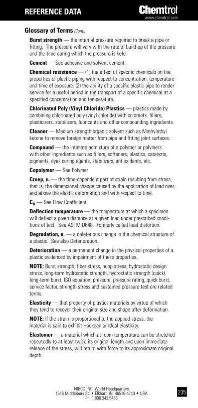
www.chemtrol.com
NIBCO INC. World Headquarters 1516 Middlebury St. • Elkhart, IN 46516-4740 • USA
Ph: 1.800.343.5455235
glossary of terms (Cont.)
burst strength — the internal pressure required to break a pipe or fitting. The pressure will vary with the rate of build-up of the pressure and the time during which the pressure is held.
cement — See adhesive and solvent cement.
chemical resistance — (1) the effect of specific chemicals on the properties of plastic piping with respect to concentration, temperature and time of exposure. (2) the ability of a specific plastic pipe to render service for a useful period in the transport of a specific chemical at a specified concentration and temperature.
chlorinated poly (Vinyl chloride) plastics — plastics made by combining chlorinated poly (vinyl chloride) with colorants, fillers, plasticizers, stabilizers, lubricants and other compounding ingredients.
cleaner — Medium strength organic solvent such as Methylethyl ketone to remove foreign matter from pipe and fitting joint surfaces.
compound — the intimate admixture of a polymer or polymers with other ingredients such as fillers, softeners, plastics, catalysts, pigments, dyes curing agents, stabilizers, antioxidants, etc.
copolymer — See Polymer
creep, n. — the time-dependent part of strain resulting from stress, that is, the dimensional change caused by the application of load over and above the elastic deformation and with respect to time.
cv — See Flow Coefficient
deflection temperature — the temperature at which a specimen will deflect a given distance at a given load under prescribed condi-tions of test. See ASTM D648. Formerly called heat distortion.
degradation, n. — a deleterious change in the chemical structure of a plastic. See also Deterioration.
deterioration — a permanent change in the physical properties of a plastic evidenced by impairment of these properties.
notE: Burst strength, fiber stress, hoop stress, hydrostatic design stress, long-term hydrostatic strength, hydrostatic strength (quick) long-term burst, ISO equation, pressure, pressure rating, quick burst, service factor, strength stress and sustained pressure test are related terms.
Elasticity — that property of plastics materials by virtue of which they tend to recover their original size and shape after deformation.
notE: If the strain is proportional to the applied stress, the material is said to exhibit Hookean or ideal elasticity.
Elastomer — a material which at room temperature can be stretched repeatedly to at least twice its original length and upon immediate release of the stress, will return with force to its approximate original depth.
REFEREncE data

NIBCO INC. World Headquarters 1516 Middlebury St. • Elkhart, IN 46516-4740 • USA
Ph: 1.800.343.5455
www.chemtrol.com
236
glossary of terms (Cont.)
Elevated temperature testing — tests on plastic pipe above 23°C (73°F).
Environmental stress cracking — cracks that develop when the material is subjected to stress in the presence of specific chemicals.
Extrusion — a method whereby heated or unheated plastic forced through a shaping orifice becomes one continuously formed piece.
notE: This method is commonly used to manufacture thermoplastic pipe.
Failure, adhesive — rupture of an adhesive bond, such that the plane of separation appears to be at the adhesive-adherend interface.
Fiber stress — the unit stress, usually in pounds per square inch (psi), in a piece of material that is subjected to an external load.
Filler — a relatively inert material added to a plastic to modify its strength, permanence, working properties or other qualities, or to lower costs.
Flow coefficient or cv — valve coefficient of flow representing the flow rate of water in gallons per minute which will produce a 1 psi pressure drop through the valve.
Full port Valve — one in which the resistance to flow, in the open position, is equal to an equivalent length of pipe.
Fungi resistance — the ability of plastic pipe to withstand fungi growth and or their metabolic products under normal conditions of ser-vice or laboratory tests simulating such conditions.
heat joining — making a pipe joint by heating the edges of the parts to be joined so that they fuse and become essentially one piece with or without the addition of additional material.
hoop stress — the tensile stress, usually in pounds per square inch (psi), in the circumferential orientation in the wall of the pipe when the pipe contains a gas or liquid under pressure.
hydrostatic design stress — the estimated maximum tensile stress in the wall of the pipe in the circumferential orientation due to internal hydrostatic pressure that can be applied continuously with a high degree of certainty that failure of the pipe will not occur.
hydrostatic strength (quick) — the hoop stress calculated by means of the ISO equation at which the pipe breaks due to an internal pressure build-up, usually within 60 to 90 seconds.
impact, izod — a specific type of impact test made with a pendulum type machine. The specimens are molded or extruded with a machined notch in the center. See ASTM D256.
REFEREncE data

www.chemtrol.com
NIBCO INC. World Headquarters 1516 Middlebury St. • Elkhart, IN 46516-4740 • USA
Ph: 1.800.343.5455237
glossary of terms (Cont.)
iso equation — an equation showing the interrelations between stress, pressure and dimensions in pipe, namely
S = P (ID + t) or P (OD - t)
2t 2t
where S = stress P = pressure ID = average inside diameter OD = average outside diameter t = minimum wall thickness
Reference: ISO R161-1960 Pipes of Plastics Materials for the Transport of Fluids (Outside Diameters and Nominal Pressures) Part I, Metric Series.
Joint — the location at which two pieces of pipe or a pipe and a fit-ting are connected together. The joint may be made by an adhesive, a solvent-cement or a mechanical device such as threads or a ring seal.
long-term burst — the internal pressure at which a pipe or fitting will break due to a constant internal pressure held for 100,000 hours (11.43 years).
long-term hydrostatic strength — the estimated tensile stress in the wall of the pipe in the circumferential orientation (hoop stress) that when applied continuously will cause failure of the pipe at 100,000 hours (11.43 years). These strengths are usually obtained by extrpolation of log-log regression equations or plots.
Molding, injection — a method of forming plastic objects from granular or powdered plastics by the fusing of plastic in a chamber with heat and pressure and then forcing part of the mass into a cooler chamber where it solidifies.
notE: This method is commonly used to manufacture thermoplastic fittings.
outdoor exposure — plastic pipe placed in service or stored so that it is not protected from the elements of normal weather conditions, i.e., the sun’s rays, rain, air and wind. Exposure to industrial and waste gases, chemicals, engine exhausts, etc., are not considered normal “outdoor exposure.”
permanence — the property of a plastic which describes its resistance to appreciable changes in characteristics with time and environment.
plastic, n. — a material that contains as an essential ingredient an organic polymeric substance of large molecular weight, is solid in its finished state and, at some stage in its manufacture or in its process-ing into finished articles, can be shaped by flow.
REFEREncE data

NIBCO INC. World Headquarters 1516 Middlebury St. • Elkhart, IN 46516-4740 • USA
Ph: 1.800.343.5455
www.chemtrol.com
238
glossary of terms (Cont.)
plastic pipe — a hollow cylinder of a plastic material in which the wall thicknesses are usually small when compared to the diameter and in which the inside and outside walls are essentially concentric. See plastic tubing.
plastic tubing, n. — a particular size of plastics pipe in which the outside diameter is essentially the same as that of copper tubing. See plastic pipe.
polypropylene, n. — a polymer prepared by the polymerization of propylene as the sole monomer.
polypropylene plastics — plastics based on polymers made with propylene as essentially the sole monomer.
poly (vinyl chloride) — a polymer prepared by the polymerization of vinyl chloride as the sole monomer.
poly (vinyl chloride) plastics — plastics made by combining poly (vinyl chloride) with colorants, fillers, plasticizers, stabilizers, lubricants, other polymers and other compounding ingredients. Not all of these modifiers are used in pipe compounds.
pressure — when expressed with reference to pipe the force per unit area exerted by the medium in the pipe.
pressure rating — the estimated maximum pressure that the medi-um in the pipe can exert continuously with a high degree of certainty that failure of the pipe will not occur.
primer — strong organic solvent, preferably tetrahydrofuran, used to dissolve and soften the joint surfaces in preparation for and prior to the application of solvent cement. Primer is usually tinted purple.
pVdF — a crystalline, high molecular weight polymer of vinylidene fluoride, containing 59 percent fluorine by weight.
quick burst — the internal pressure required to burst a pipe or fitting due to an internal pressure build-up, usually within 60 to 90 seconds.
schedule — a pipe size system (outside diameters and wall thick-nesses) originated by the iron pipe industry.
self-extinguishing — the ability of a plastic to resist burning when the source of heat or flame that ignited it is removed.
service factor — a factor which is used to reduce a strength value to obtain an engineering design stress. The factor may vary depending on the service conditions, the hazard, the length of service desired and the properties of the pipe.
solvent cement — in the plastic piping field, a solvent adhesive that contains a solvent that dissolves or softens the surfaces being bonded so that the bonded assembly becomes essentially one piece of the same type of plastic.
solvent cementing — making a pipe joint with a solvent cement. See Solvent Cement.
REFEREncE data
www.chemtrol.com
NIBCO INC. World Headquarters 1516 Middlebury St. • Elkhart, IN 46516-4740 • USA
Ph: 1.800.343.5455239
glossary of terms (Cont.)
stress — when expressed with reference to pipe the force per unit area in the wall of the pipe in the circumferential orientation due to internal hydrostatic pressure.
sustained pressure test — a constant internal pressure test for 1,000 hours.
thermoplastic — a plastic which is thermoplastic in behavior. Capable of being repeatedly softened by increase of temperature and hardened by decrease of temperature.
throttling valve — a valve that is used for control of flow rate.
Union — a device placed in a pipeline to facilitate disassembly of the system.
Vinyl chloride plastics — plastics based on polymers of vinyl chloride or copolymers of vinyl chloride with other monomers, the vinyl chloride being in greatest amount by mass.
weld-or knit-line — a mark on a molded plastic part formed by the union of two or more streams of plastic flowing together.
REFEREncE data

NIBCO INC. World Headquarters 1516 Middlebury St. • Elkhart, IN 46516-4740 • USA
Ph: 1.800.343.5455
www.chemtrol.com
240
notEs
www.chemtrol.com
NIBCO INC. World Headquarters 1516 Middlebury St. • Elkhart, IN 46516-4740 • USA
Ph: 1.800.343.5455241
notEs

NIBCO INC. World Headquarters 1516 Middlebury St. • Elkhart, IN 46516-4740 • USA
Ph: 1.800.343.5455
www.chemtrol.com
242
notEs


Plastic Piping Handbook
Chem
trol
® T
herm
opla
stic
Flo
w S
olut
ions
Every solution begins with a good idea.
We’ve got ideas that flow
directly to solutions for
your industrial piping
applications. Ideas that
make your installations
easier and more cost-
effective. Ideas that work,
and ideas that last. Our
ideas are strengthened by
a sound foundation for
growth and a solid
commitment to service.
For ideas that fit your
flow-control applications,
call on us. We’re Chemtrol,
a product line committed
to innovation, growth,
and superiority in
thermoplastics—
ideas whose time
has come.
CH-HB-0914
NIBCO INC.World Headquarters1516 Middlebury StreetElkhart, IN 46516-4740USA
Phone: 800.343.5455Fax: 800.541.3841
Technical Service: Phone: 888.446.4226
International Office: Phone: +1.574.295.3327Fax: +1.574.295.3455
www.chemtrol.com
Corzan® is a registered trademark of The Lubrizol Corporation.Tru-Bloc® is a registered trademark of NIBCO INC.Chem-Pure® is a registered trademark of NIBCO INC.Chemcock® is a registered trademark of NIBCO INC.Kynar® is a registered trademark of Arkema Inc.
Ideas that flow.
- Plastic Piping Handbook
Chemtrol® is a brand of
Related Documents


![Modeling FRP and Plastic Piping-R11[1]](https://static.cupdf.com/doc/110x72/55cf9839550346d033965908/modeling-frp-and-plastic-piping-r111.jpg)


