— MAIN CATALOG OPR lightning protection systems External lightning protection — OPR lightning protection systems External lightning protection

Welcome message from author
This document is posted to help you gain knowledge. Please leave a comment to let me know what you think about it! Share it to your friends and learn new things together.
Transcript
—MAIN C ATALOG
OPR lightning protection systemsExternal lightning protection
—
OPR
lig
htni
ng p
rote
ctio
n sy
stem
sE
xter
nal
lig
htni
ng
pro
tect
ion

Draft, ne pas diffuser Mon Sep 27 2021 14:34:57 GMT+0200 (Romance Standard Time)
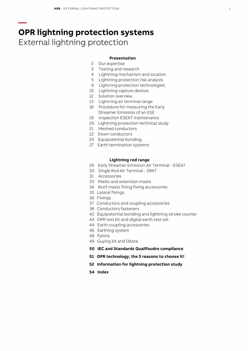
ABB EXTERNAL LIGHTNING PROTECTION 1
—OPR lightning protection systems External lightning protection
Presentation2 Our expertise3 Testing and research
4 Lightning mechanism and location 5 Lightning protection risk analysis 6 Lightning protection technologies 10 Lightning capture devices 12 Solution overview 13 Lightning air terminal range 18 Procedure for measuring the Early Streamer Emission of an ESE 19 Inspection ESEAT maintenance 20 Lightning protection technical study 21 Meshed conductors 22 Down conductors 25 Equipotential bonding 27 Earth termination systems
Lightning rod range 29 Early Streamer Emission Air Terminal - ESEAT 30 Single Rod Air Terminal - SRAT 31 Accessories 33 Masts and extension masts 34 Roof masts fixing fixing accessories 35 Lateral fixings 36 Fixings 37 Conductors and coupling accessories 38 Conductors fasteners 42 Equipotential bonding and lightning stroke counter 43 OPR test kit and digital earth test set 44 Earth coupling accessories 46 Earthing system 48 Pylons 49 Guying kit and Obsta
50 IEC and Standards Qualifoudre compliance
51 OPR technology, the 5 reasons to choose it!
52 Information for lightning protection study
54 Index
2 ABB EXTERNAL LIGHTNING PROTECTION
— Our expertiseControl of high amplitude and short duration currents
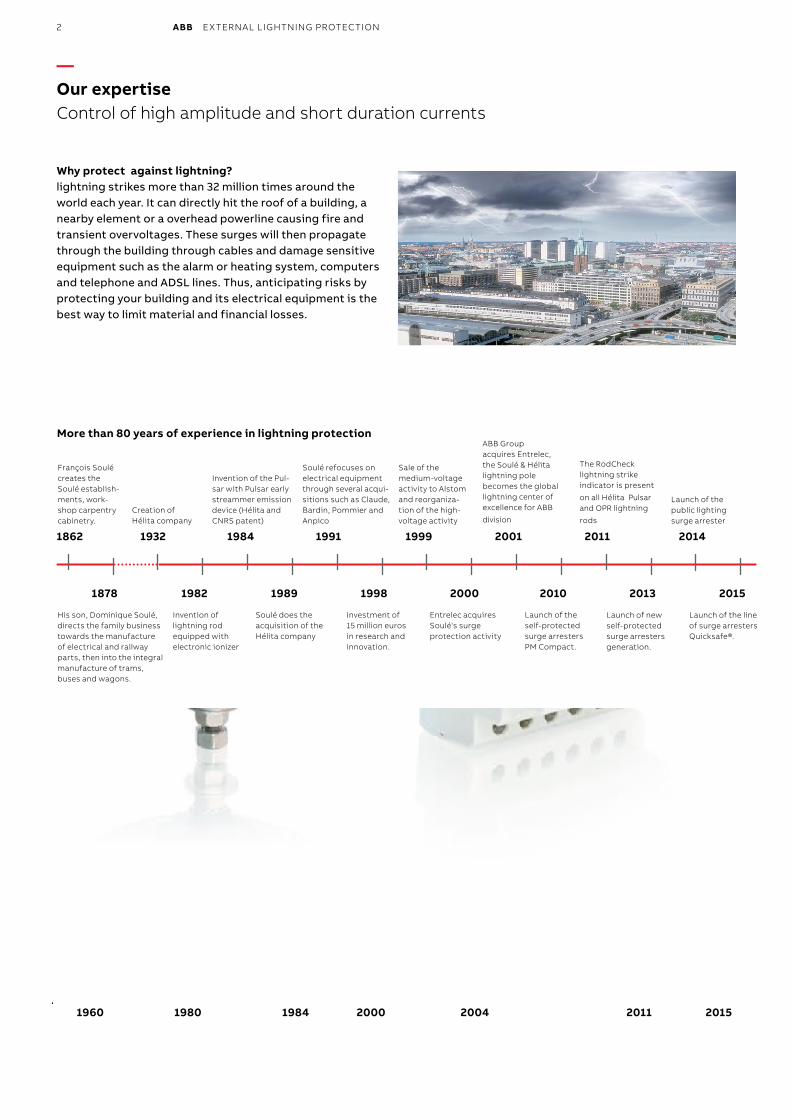
Why protect against lightning?lightning strikes more than 32 million times around the world each year. It can directly hit the roof of a building, a nearby element or a overhead powerline causing fire and transient overvoltages. These surges will then propagate through the building through cables and damage sensitive equipment such as the alarm or heating system, computers and telephone and ADSL lines. Thus, anticipating risks by protecting your building and its electrical equipment is the best way to limit material and financial losses.
1960 1980 1984 2000 2004 2011 2015
More than 80 years of experience in lightning protection
1862 1932 1984 19991991 2001 2011 2014
1878 1982 1989 20001998 2015
François Soulé creates the Soulé establish-ments, work-shop carpentry cabinetry.
Invention of the Pul-sar with Pulsar early streammer emission device (Hélita and CNRS patent)
Soulé refocuses on electrical equipment through several acqui-sitions such as Claude, Bardin, Pommier and Anpico
Sale of the medium-voltage activity to Alstom and reorganiza-tion of the high-voltage activity
ABB Groupacquires Entrelec, the Soulé & Hélita lightning pole becomes the global lightning center of excellence for ABB
division
Launch of the public lighting surge arrester
The RodCheck lightning strike indicator is present
on all Hélita Pulsar and OPR lightning
rodsCreation of Hélita company
His son, Dominique Soulé, directs the family business towards the manufacture of electrical and railway parts, then into the integral manufacture of trams, buses and wagons.
Invention of lightning rod equipped with electronic ionizer
Soulé does the acquisition of the Hélita company
Investment of 15 million euros in research and innovation.
Entrelec acquires Soulé's surge protection activity
Launch of the self-protected surge arresters PM Compact.
2010
Launch of new self-protected surge arresters generation.
Launch of the line of surge arresters Quicksafe®.
2013
Magalie Gaber-Melek
Stamp
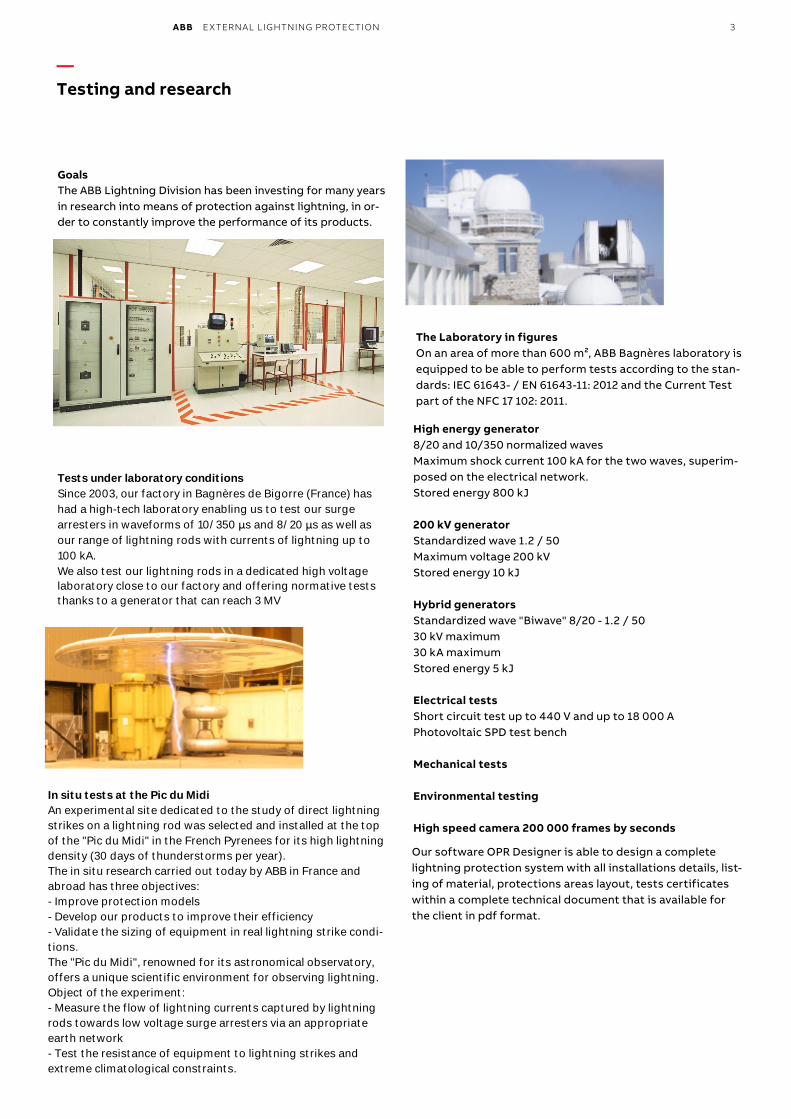
ABB EXTERNAL LIGHTNING PROTECTION 3
—Testing and research
GoalsThe ABB Lightning Division has been investing for many years in research into means of protection against lightning, in or-der to constantly improve the performance of its products.
Tests under laboratory conditionsSince 2003, our factory in Bagnères de Bigorre (France) hashad a high-tech laboratory enabling us to test our surgearresters in waveforms of 10/350 μs and 8/20 μs as well asour range of lightning rods with currents of lightning up to100 kA.We also test our lightning rods in a dedicated high voltagelaboratory close to our factory and offering normative teststhanks to a generator that can reach 3 MV
Our software OPR Designer is able to design a complete lightning protection system with all installations details, list-ing of material, protections areas layout, tests certificates within a complete technical document that is available for the client in pdf format.
The Laboratory in figuresOn an area of more than 600 m², ABB Bagnères laboratory is equipped to be able to perform tests according to the stan-dards: IEC 61643- / EN 61643-11: 2012 and the Current Test part of the NFC 17 102: 2011.
High energy generator8/20 and 10/350 normalized wavesMaximum shock current 100 kA for the two waves, superim-posed on the electrical network.Stored energy 800 kJ
200 kV generatorStandardized wave 1.2 / 50Maximum voltage 200 kVStored energy 10 kJ
Hybrid generatorsStandardized wave "Biwave" 8/20 - 1.2 / 5030 kV maximum30 kA maximumStored energy 5 kJ
Electrical testsShort circuit test up to 440 V and up to 18 000 APhotovoltaic SPD test bench
Mechanical tests
Environmental testing
High speed camera 200 000 frames by seconds
In situ tests at the Pic du MidiAn experimental site dedicated to the study of direct lightningstrikes on a lightning rod was selected and installed at the topof the "Pic du Midi" in the French Pyrenees for its high lightningdensity (30 days of thunderstorms per year).The in situ research carried out today by ABB in France andabroad has three objectives:- Improve protection models- Develop our products to improve their efficiency- Validate the sizing of equipment in real lightning strike condi-tions.The "Pic du Midi", renowned for its astronomical observatory,offers a unique scientific environment for observing lightning.Object of the experiment:- Measure the flow of lightning currents captured by lightningrods towards low voltage surge arresters via an appropriateearth network- Test the resistance of equipment to lightning strikes andextreme climatological constraints.
Magalie Gaber-Melek
Stamp
Magalie Gaber-Melek
Stamp
4 ABB EXTERNAL LIGHTNING PROTECTION
— Lightning mechanism and location
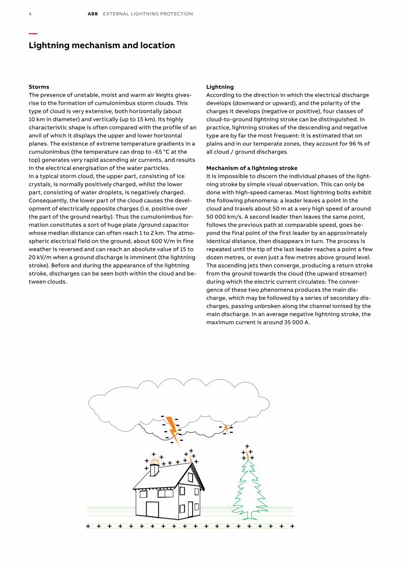
StormsThe presence of unstable, moist and warm air Weights gives-rise to the formation of cumulonimbus storm clouds. This type of cloud is very extensive, both horizontally (about 10 km in diameter) and vertically (up to 15 km). Its highly characteristic shape is often compared with the profile of an anvil of which it displays the upper and lower horizontal planes. The existence of extreme temperature gradients in a cumulonimbus (the temperature can drop to -65 °C at the top) generates very rapid ascending air currents, and results in the electrical energisation of the water particles.In a typical storm cloud, the upper part, consisting of icecrystals, is normally positively charged, whilst the lower part, consisting of water droplets, is negatively charged. Consequently, the lower part of the cloud causes the devel-opment of electrically opposite charges (i.e. positive over the part of the ground nearby). Thus the cumulonimbus for-mation constitutes a sort of huge plate /ground capacitor whose median distance can often reach 1 to 2 km. The atmo-spheric electrical field on the ground, about 600 V/m in fine weather is reversed and can reach an absolute value of 15 to 20 kV/m when a ground discharge is imminent (the lightning stroke). Before and during the appearance of the lightning stroke, discharges can be seen both within the cloud and be-tween clouds.
LightningAccording to the direction in which the electrical discharge develops (downward or upward), and the polarity of the charges it develops (negative or positive), four classes of cloud-to-ground lightning stroke can be distinguished. In practice, lightning strokes of the descending and negative type are by far the most frequent: it is estimated that on plains and in our temperate zones, they account for 96 % of all cloud / ground discharges.
Mechanism of a lightning strokeIt is impossible to discern the individual phases of the light-ning stroke by simple visual observation. This can only be done with high-speed cameras. Most lightning bolts exhibit the following phenomena: a leader leaves a point in the cloud and travels about 50 m at a very high speed of around 50 000 km/s. A second leader then leaves the same point, follows the previous path at comparable speed, goes be-yond the final point of the first leader by an approximately identical distance, then disappears in turn. The process is repeated until the tip of the last leader reaches a point a few dozen metres, or even just a few metres above ground level.The ascending jets then converge, producing a return stroke from the ground towards the cloud (the upward streamer) during which the electric current circulates: The conver-gence of these two phenomena produces the main dis-charge, which may be followed by a series of secondary dis-charges, passing unbroken along the channel ionised by the main discharge. In an average negative lightning stroke, the maximum current is around 35 000 A.
-----
-----
- -- -
++
+ ++
++ ++
++
++
++
++
+ + + + + + + + + + + + + + + + + + + +
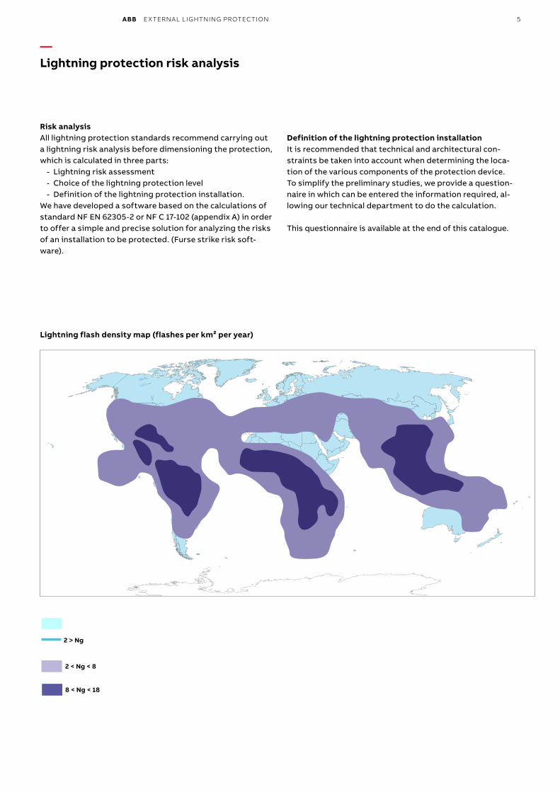
ABB EXTERNAL LIGHTNING PROTECTION 5
— Lightning protection risk analysis
Risk analysisAll lightning protection standards recommend carrying out a lightning risk analysis before dimensioning the protection, which is calculated in three parts:
- Lightning risk assessment - Choice of the lightning protection level - Definition of the lightning protection installation.
We have developed a software based on the calculations of standard NF EN 62305-2 or NF C 17-102 (appendix A) in order to offer a simple and precise solution for analyzing the risks of an installation to be protected. (Furse strike risk soft-ware).
Definition of the lightning protection installationIt is recommended that technical and architectural con-straints be taken into account when determining the loca-tion of the various components of the protection device. To simplify the preliminary studies, we provide a question-naire in which can be entered the information required, al-lowing our technical department to do the calculation.
This questionnaire is available at the end of this catalogue.
Lightning flash density map (flashes per km² per year)
2 < Ng < 8
8 < Ng < 18
2 > Ng
Magalie Gaber-Melek
Rectangle
6 ABB EXTERNAL LIGHTNING PROTECTION
— Lightning protection technologies
The effects of lightningThe effects of lightning are those of a high-strength impulse current that propagates initially in a gaseous environment (the atmosphere), and then in a solid, more or less conduc-tive medium (the ground):
- visual effects (flash): caused by the Townsend avalanche mechanism
- acoustic effects: caused by the propagation of a shock wave (rise in pressure) originating in the discharge path; this effect is perceptible up to a range of around 10 km
- thermal effect: heat generated by the Joule effect in the ionised channel
- electrodynamic effects: these are the mechanical forces applied to the conductors placed in a magnetic field cre-ated by the high voltage circulation. They may result in deformations
- electrochemical effects: these relatively minor effects are conveyed in the form of electrolytic decomposition through the application of Faraday's law
- induction effects: in a variable electromagnetic field, every conductor harnesses induced current
- effects on a living being (human or animal): the passage of a transient current of a certain r.m.s value is sufficient to incur risks of electrocution by heart attack or respira-tory failure, together with the risk of burns.
Lightning causes two major types of accidents: - accidents caused by a direct stroke when the lightning
strikes a building or a specific zone. This can cause con-siderable damage, usually by fire. Protection against this danger is provided by lightning air terminal systems
- accidents caused indirectly, as when the lightning strikes or causes power surges in power cables or transmission links. Hence the need to protect with SPD the equipment at risk against the surge voltage and indirect currents generated.
Protection against direct lightning strokeTo protect a structure against lightning strokes, a preferred impact point is selected to protect the surrounding struc-ture and conduct the flow of the electric current towards the ground, with minimal impedance on the path followed by the lightning. Four types of protection systems meet these requirements.
Protection systems Standard
Early streamer emission air terminal France NFC 17-102 (september 2011 edition)Single rods air terminals NF IEC EN 62 305-3Meshed cages NF IEC EN 62 305-3Stretched wires NF IEC EN 62 305-3
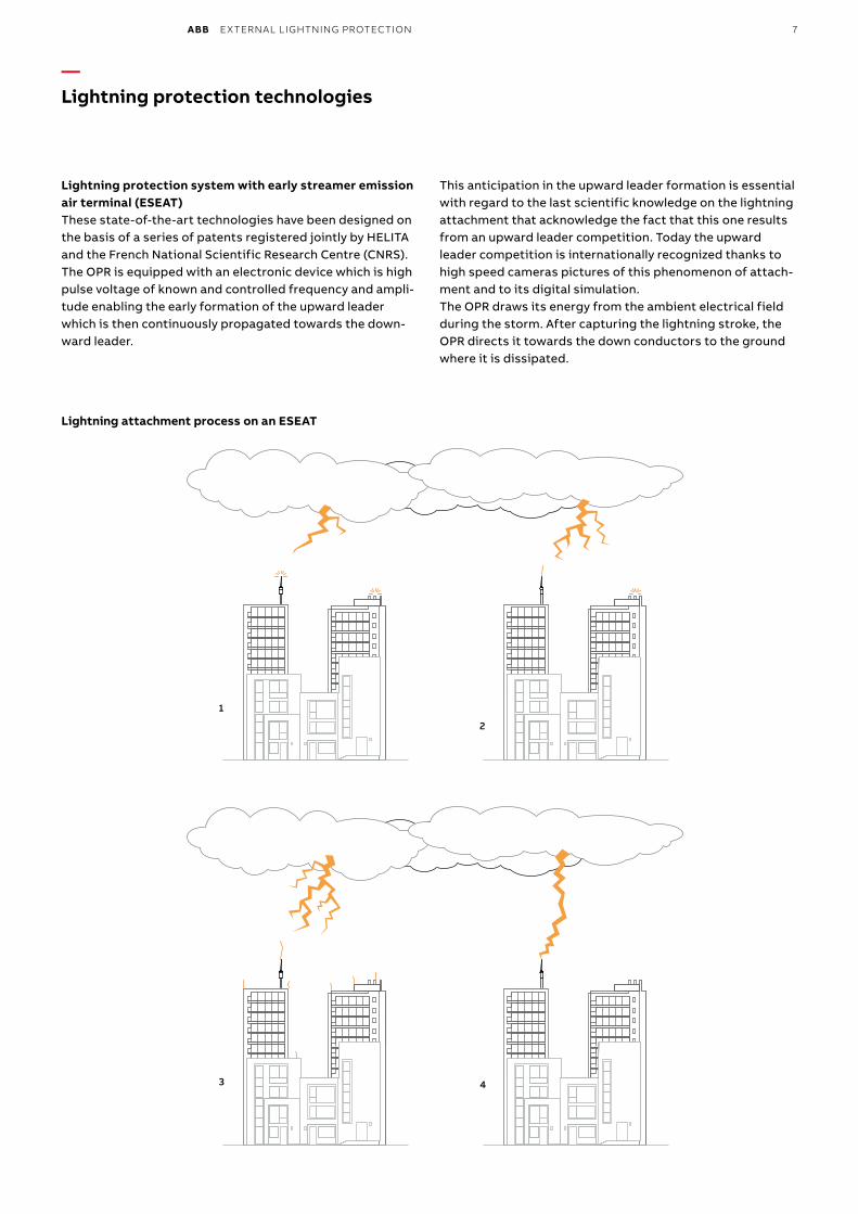
ABB EXTERNAL LIGHTNING PROTECTION 7
Lightning protection system with early streamer emission air terminal (ESEAT)These state-of-the-art technologies have been designed on the basis of a series of patents registered jointly by HELITA and the French National Scientific Research Centre (CNRS). The OPR is equipped with an electronic device which is high pulse voltage of known and controlled frequency and ampli-tude enabling the early formation of the upward leader which is then continuously propagated towards the down-ward leader.
This anticipation in the upward leader formation is essential with regard to the last scientific knowledge on the lightning attachment that acknowledge the fact that this one results from an upward leader competition. Today the upward leader competition is internationally recognized thanks to high speed cameras pictures of this phenomenon of attach-ment and to its digital simulation. The OPR draws its energy from the ambient electrical field during the storm. After capturing the lightning stroke, the OPR directs it towards the down conductors to the ground where it is dissipated.
Lightning attachment process on an ESEAT
1
2
— Lightning protection technologies
3 4
8 ABB EXTERNAL LIGHTNING PROTECTION
The early streamer emission (ESE) conceptDuring a storm, when the propagation field conditions are favorable, the OPR first generates an upward leader. This leader from the OPR tip propagates towards the downward leader from the cloud.The triggering time ∆T (µs) is defined as the mean gain atthe sparkover instant (continuous propagation of the up-ward leader) obtained with an ESE air terminal compared with a single rod air terminal exposed to the same condi-tions. ∆T is measured in the high-voltage laboratory, all tests are defined in appendix C of the French standard NF C 17-102.
The triggering time instance gain ∆T is associated with a triggering time distance gain ∆L.
- ∆T = ∆L, where:- ∆L (m): gain in lead distance or sparkover distance - ∆T (µs): gain in sparkover time of the upward leader mea-
sured in laboratory conditions.OPR air terminals are especially effective for the protectionof classified industrial sites, administrative or public build-ings, historical monuments and open-air sites such as sports grounds.
— Lightning protection technologies
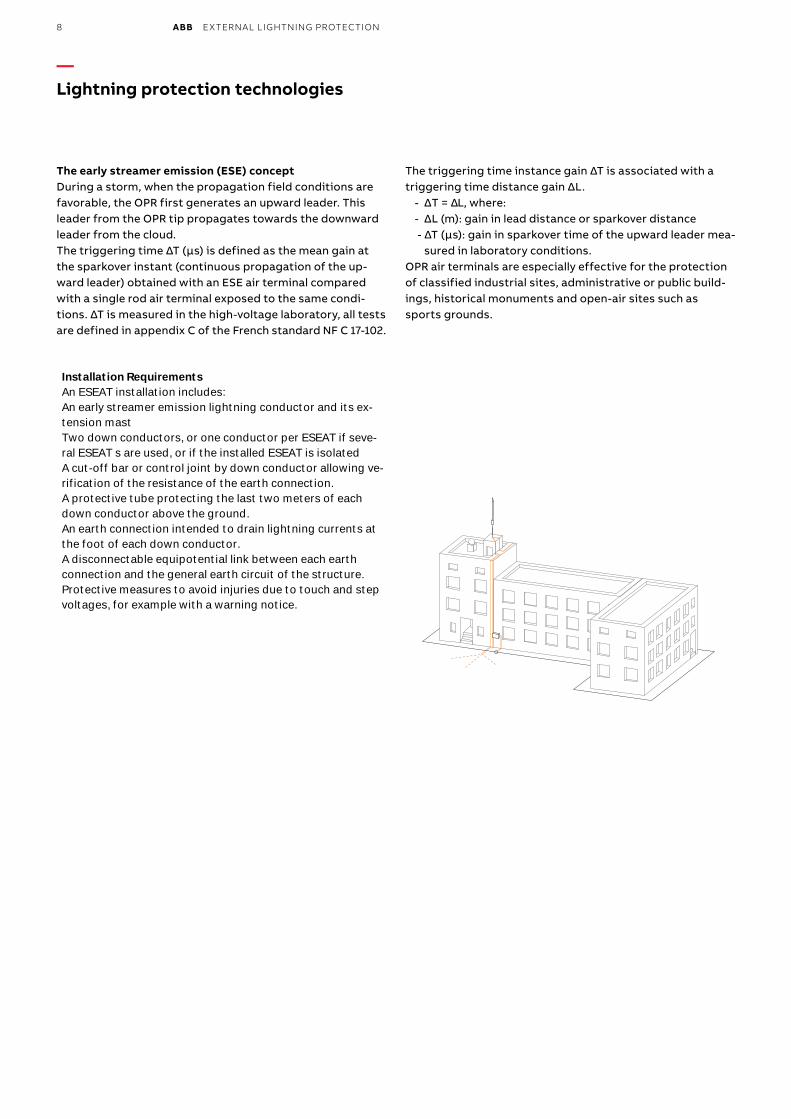
Installation RequirementsAn ESEAT installation includes:An early streamer emission lightning conductor and its ex-tension mastTwo down conductors, or one conductor per ESEAT if seve-ral ESEAT s are used, or if the installed ESEAT is isolatedA cut-off bar or control joint by down conductor allowing ve-rification of the resistance of the earth connection.A protective tube protecting the last two meters of eachdown conductor above the ground.An earth connection intended to drain lightning currents atthe foot of each down conductor.A disconnectable equipotential link between each earthconnection and the general earth circuit of the structure.Protective measures to avoid injuries due to touch and stepvoltages, for example with a warning notice.
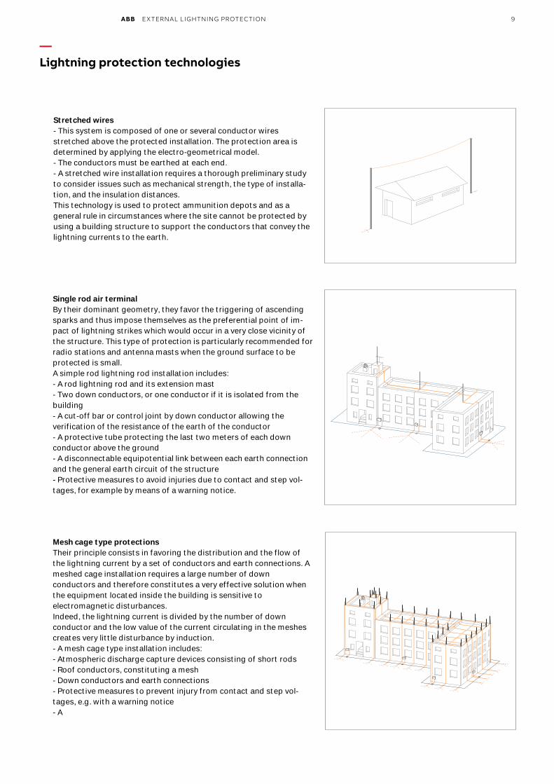
ABB EXTERNAL LIGHTNING PROTECTION 9
— Lightning protection technologies
Mesh cage type protectionsTheir principle consists in favoring the distribution and the flow ofthe lightning current by a set of conductors and earth connections. Ameshed cage installation requires a large number of downconductors and therefore constitutes a very effective solution whenthe equipment located inside the building is sensitive toelectromagnetic disturbances.Indeed, the lightning current is divided by the number of downconductor and the low value of the current circulating in the meshescreates very little disturbance by induction.- A mesh cage type installation includes:- Atmospheric discharge capture devices consisting of short rods- Roof conductors, constituting a mesh- Down conductors and earth connections- Protective measures to prevent injury from contact and step vol-tages, e.g. with a warning notice- A
Stretched wires- This system is composed of one or several conductor wiresstretched above the protected installation. The protection area isdetermined by applying the electro-geometrical model.- The conductors must be earthed at each end.- A stretched wire installation requires a thorough preliminary studyto consider issues such as mechanical strength, the type of installa-tion, and the insulation distances.This technology is used to protect ammunition depots and as ageneral rule in circumstances where the site cannot be protected byusing a building structure to support the conductors that convey thelightning currents to the earth.
Single rod air terminalBy their dominant geometry, they favor the triggering of ascendingsparks and thus impose themselves as the preferential point of im-pact of lightning strikes which would occur in a very close vicinity ofthe structure. This type of protection is particularly recommended forradio stations and antenna masts when the ground surface to beprotected is small.A simple rod lightning rod installation includes:- A rod lightning rod and its extension mast- Two down conductors, or one conductor if it is isolated from thebuilding- A cut-off bar or control joint by down conductor allowing theverification of the resistance of the earth of the conductor- A protective tube protecting the last two meters of each downconductor above the ground- A disconnectable equipotential link between each earth connectionand the general earth circuit of the structure- Protective measures to avoid injuries due to contact and step vol-tages, for example by means of a warning notice.
10 ABB EXTERNAL LIGHTNING PROTECTION
— Lightning capture devices
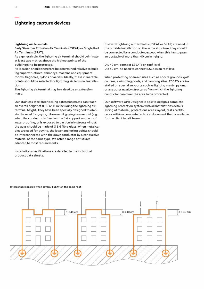
Lightning air terminalsEarly Streamer Emission Air Terminals (ESEAT) or Single Rod Air Terminals (SRAT).As a general rule, the lightning air terminal should culminate at least two metres above the highest points of the building(s) to be protected. Its location should therefore be determined relative to build-ing superstructures: chimneys, machine and equipment rooms, flagpoles, pylons or aerials. Ideally, these vulnerable points should be selected for lightning air terminal installa-tion. The lightning air terminal may be raised by an extension mast.
Our stainless steel interlocking extension masts can reach an overall height of 8.50 or 11 m including the lightning air terminal height. They have been specially designed to obvi-ate the need for guying. However, if guying is essential (e.g. when the conductor is fixed with a flat support on the roof waterproofing, or is exposed to particularly strong winds), the guys should be made of Ø 5.6 fibre glass. When metal ca-bles are used for guying, the lower anchoring points should be interconnected with the down conductor by a conductive material of the same type. We offer a range of fixtures adapted to most requirements.
Installation specifications are detailed in the individual product data sheets.
If several lightning air terminals (ESEAT or SRAT) are used in the outside installation on the same structure, they should be connected by a conductor, except when this has to pass an obstacle of more than 40 cm in height.
D ≤ 40 cm: connect ESEATs on roof levelD ≥ 40 cm: no need to connect ESEATs on roof level
When protecting open-air sites such as sports grounds, golf courses, swimming pools, and camping sites, ESEATs are in-stalled on special supports such as lighting masts, pylons,or any other nearby structures from which the lightning
conductor can cover the area to be protected.
Our software OPR Designer is able to design a complete lightning protection system with all installations details, listing of material, protections areas layout, tests certifi-cates within a complete technical document that is available for the client in pdf format.
d ≤ 40 cmd ≤ 40 cmd ≤ 40 cm
Interconnection rule when several ESEAT on the same roof
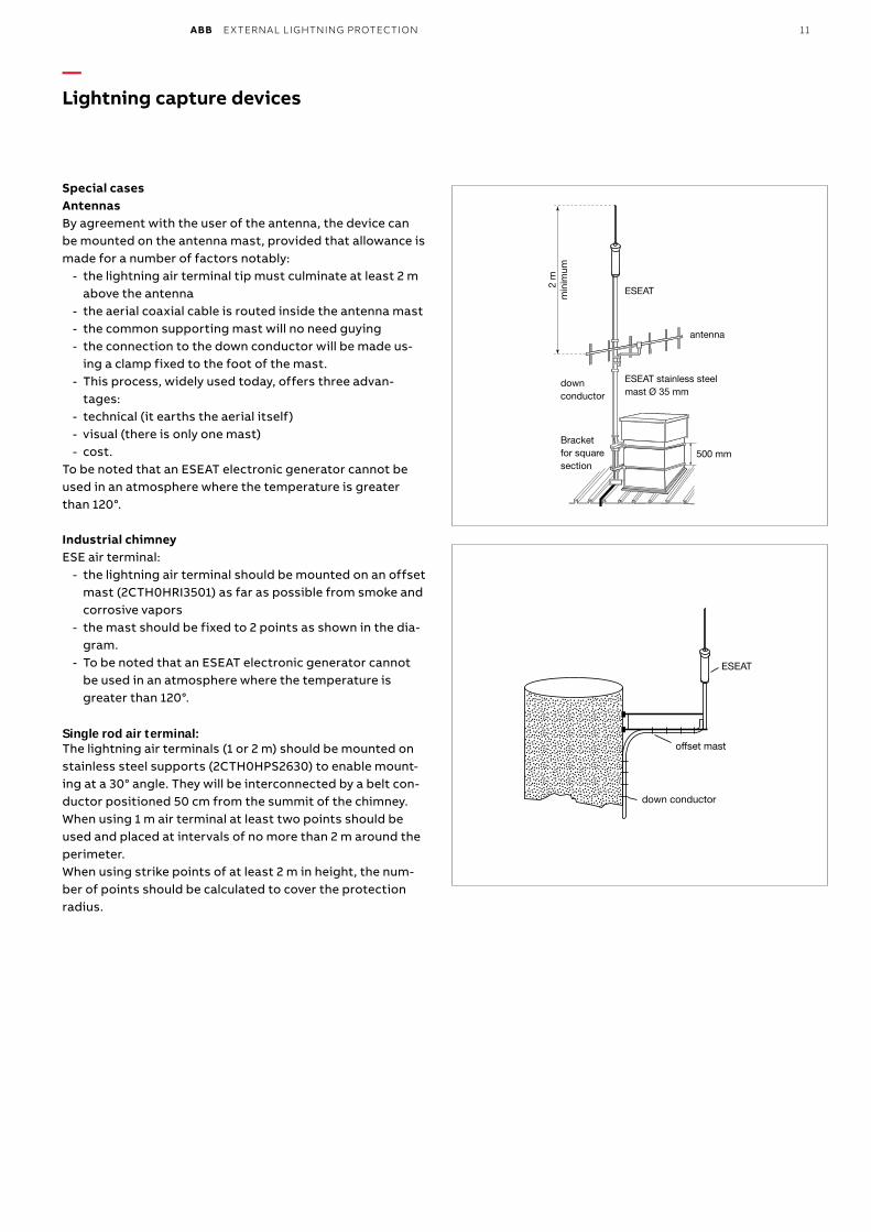
ABB EXTERNAL LIGHTNING PROTECTION 11
— Lightning capture devices
Special casesAntennasBy agreement with the user of the antenna, the device can be mounted on the antenna mast, provided that allowance is made for a number of factors notably:
- the lightning air terminal tip must culminate at least 2 m above the antenna
- the aerial coaxial cable is routed inside the antenna mast - the common supporting mast will no need guying - the connection to the down conductor will be made us-
ing a clamp fixed to the foot of the mast. - This process, widely used today, offers three advan-
tages: - technical (it earths the aerial itself) - visual (there is only one mast) - cost.
To be noted that an ESEAT electronic generator cannot be used in an atmosphere where the temperature is greater than 120°.
Industrial chimneyESE air terminal:
- the lightning air terminal should be mounted on an offset mast (2CTH0HRI3501) as far as possible from smoke and corrosive vapors
- the mast should be fixed to 2 points as shown in the dia-gram.
- To be noted that an ESEAT electronic generator cannot be used in an atmosphere where the temperature is greater than 120°.
Single rod air terminal:The lightning air terminals (1 or 2 m) should be mounted on stainless steel supports (2CTH0HPS2630) to enable mount-ing at a 30° angle. They will be interconnected by a belt con-ductor positioned 50 cm from the summit of the chimney. When using 1 m air terminal at least two points should be used and placed at intervals of no more than 2 m around the perimeter.When using strike points of at least 2 m in height, the num-ber of points should be calculated to cover the protection radius.
2 m
min
imum
ESEAT
ESEAT stainless steel mast Ø 35 mm
500 mm
antenna
Bracket for square section
down conductor
ESEAT
offset mast
down conductor
12 ABB EXTERNAL LIGHTNING PROTECTION
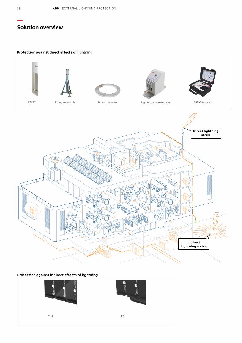
—Solution overview
Protection against indirect effects of lightning
T1+2 T2
Direct lightning strike
Indirect lightning strike
Protection against direct effects of lightning
ESEAT Fixing accessories Down conductor ESEAT test setLightning stroke counter
Magalie Gaber-Melek
Stamp
Magalie Gaber-Melek
Stamp
Magalie Gaber-Melek
Stamp
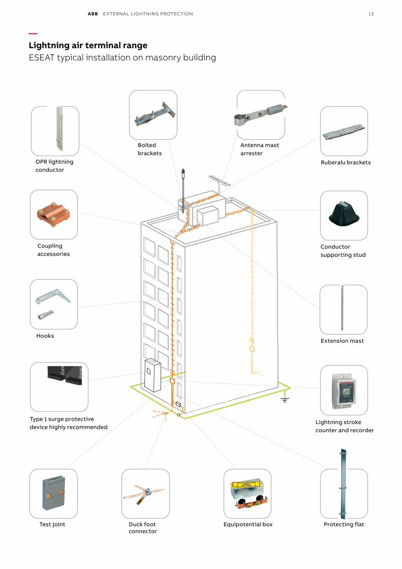
ABB EXTERNAL LIGHTNING PROTECTION 13
— Lightning air terminal rangeESEAT typical installation on masonry building
OPR lightning conductor
Coupling accessories
Hooks
Test joint Duck foot connector
Lightning stroke counter and recorder
Extension mast
Conductor supporting stud
Ruberalu brackets
Antenna mast arrester
Bolted brackets
Protecting flatEquipotential box
Type 1 surge protective device highly recommended
Magalie Gaber-Melek
Stamp
Magalie Gaber-Melek
Stamp
14 ABB EXTERNAL LIGHTNING PROTECTION
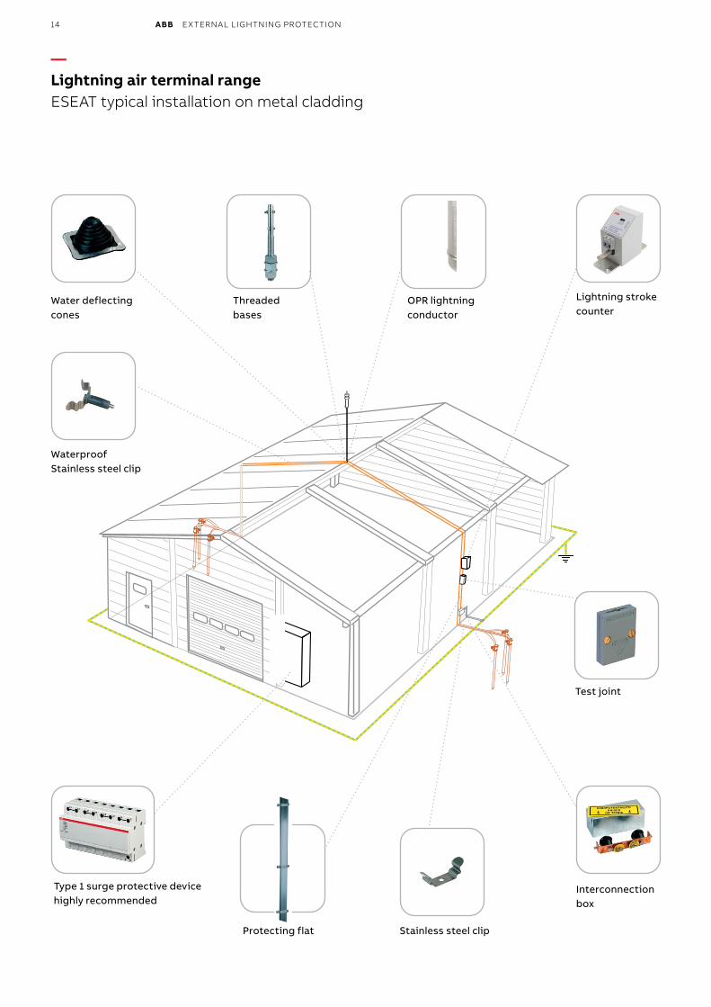
— Lightning air terminal rangeESEAT typical installation on metal cladding
Threaded bases
Test joint
Interconnection box
Stainless steel clipProtecting flat
Water deflecting cones
WaterproofStainless steel clip
Type 1 surge protective devicehighly recommended
Lightning stroke counter
OPR lightning conductor
Magalie Gaber-Melek
Stamp
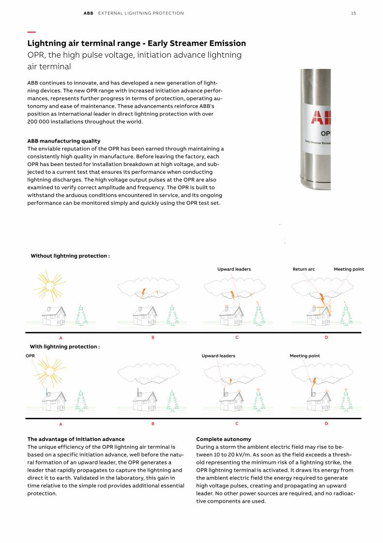
ABB EXTERNAL LIGHTNING PROTECTION 15
— Lightning air terminal range - Early Streamer EmissionOPR, the high pulse voltage, initiation advance lightning air terminal
ABB continues to innovate, and has developed a new generation of light-ning devices. The new OPR range with increased initiation advance perfor-mances, represents further progress in terms of protection, operating au-tonomy and ease of maintenance. These advancements reinforce ABB's position as International leader in direct lightning protection with over 200 000 installations throughout the world.
ABB manufacturing qualityThe enviable reputation of the OPR has been earned through maintaining a consistently high quality in manufacture. Before leaving the factory, each OPR has been tested for installation breakdown at high voltage, and sub-jected to a current test that ensures its performance when conducting lightning discharges. The high voltage output pulses at the OPR are also examined to verify correct amplitude and frequency. The OPR is built to withstand the arduous conditions encountered in service, and its ongoing performance can be monitored simply and quickly using the OPR test set.
The advantage of initiation advanceThe unique efficiency of the OPR lightning air terminal is based on a specific initiation advance, well before the natu-ral formation of an upward leader, the OPR generates a leader that rapidly propagates to capture the lightning and direct it to earth. Validated in the laboratory, this gain in time relative to the simple rod provides additional essential protection.
Complete autonomyDuring a storm the ambient electric field may rise to be-tween 10 to 20 kV/m. As soon as the field exceeds a thresh-old representing the minimum risk of a lightning strike, the OPR lightning terminal is activated. It draws its energy from the ambient electric field the energy required to generate high voltage pulses, creating and propagating an upward leader. No other power sources are required, and no radioac-tive components are used.
A B C D
OPR Upward leaders Meeting point
A B C D
Upward leaders Meeting pointReturn arc
With lightning protection :
Without lightning protection :
Magalie Gaber-Melek
Stamp
16 ABB EXTERNAL LIGHTNING PROTECTION
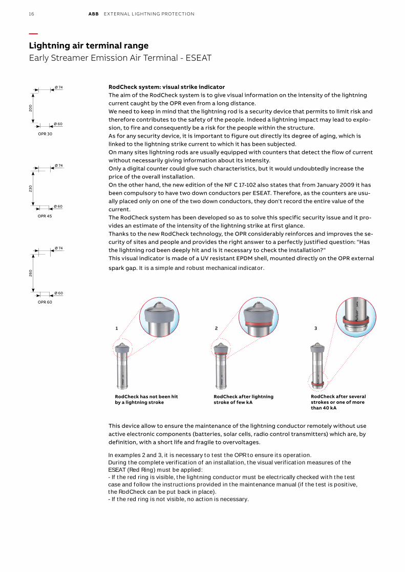
RodCheck system: visual strike indicatorThe aim of the RodCheck system is to give visual information on the intensity of the lightning current caught by the OPR even from a long distance.We need to keep in mind that the lightning rod is a security device that permits to limit risk and therefore contributes to the safety of the people. Indeed a lightning impact may lead to explo-sion, to fire and consequently be a risk for the people within the structure.As for any security device, it is important to figure out directly its degree of aging, which is linked to the lightning strike current to which it has been subjected.On many sites lightning rods are usually equipped with counters that detect the flow of current without necessarily giving information about its intensity.Only a digital counter could give such characteristics, but it would undoubtedly increase the price of the overall installation.On the other hand, the new edition of the NF C 17-102 also states that from January 2009 it has been compulsory to have two down conductors per ESEAT. Therefore, as the counters are usu-ally placed only on one of the two down conductors, they don't record the entire value of the current.The RodCheck system has been developed so as to solve this specific security issue and it pro-vides an estimate of the intensity of the lightning strike at first glance.Thanks to the new RodCheck technology, the OPR considerably reinforces and improves the se-curity of sites and people and provides the right answer to a perfectly justified question: "Has the lightning rod been deeply hit and is it necessary to check the installation?"This visual indicator is made of a UV resistant EPDM shell, mounted directly on the OPR external
spark gap. It is a simple and robust mechanical indicator.
RodCheck has not been hit by a lightning stroke
RodCheck after lightning stroke of few kA
RodCheck after several strokes or one of more than 40 kA
— Lightning air terminal rangeEarly Streamer Emission Air Terminal - ESEAT
1 2 3
This device allow to ensure the maintenance of the lightning conductor remotely without use active electronic components (batteries, solar cells, radio control transmitters) which are, by definition, with a short life and fragile to overvoltages.
230
Ø 74
Ø 60
OPR 45
Ø 74
200
OPR 30
Ø 60
260
OPR 60
Ø 60
Ø 74
In examples 2 and 3, it is necessary to test the OPR to ensure its operation.During the complete verification of an installation, the visual verification measures of theESEAT (Red Ring) must be applied:- If the red ring is visible, the lightning conductor must be electrically checked with the testcase and follow the instructions provided in the maintenance manual (if the test is positive,the RodCheck can be put back in place).- If the red ring is not visible, no action is necessary.
Bruno Roland
Rectangle
Magalie Gaber-Melek
Stamp
Magalie Gaber-Melek
Stamp
Magalie Gaber-Melek
Stamp
Magalie Gaber-Melek
Rectangle
Magalie Gaber-Melek
Rectangle
Magalie Gaber-Melek
Rectangle
Magalie Gaber-Melek
Rectangle
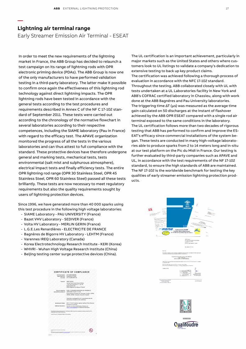
ABB EXTERNAL LIGHTNING PROTECTION 17
—Lightning air terminal rangeEarly Streamer Emission Air Terminal - ESEAT
In order to meet the new requirements of the lightning market in France, the ABB Group has decided to relaunch a test campaign on its range of lightning rods with OPR electronic priming device (PDAs). The ABB Group is now one of the only manufacturers to have performed validation testing in a third-party laboratory. The latter make it possible to confirm once again the effectiveness of this lightning rod technology against direct lightning impacts. The OPR lightning rods have been tested in accordance with the general tests according to the test procedures and requirements described in Annex C of the NF C 17-102 stan-dard of September 2011. These tests were carried out according to the chronology of the normative flowchart in several laboratories according to their respective competences, including the SIAME laboratory (Pau in France) with regard to the efficacy test. The APAVE organization monitored the progress of all the tests in the various laboratories and can thus attest to full compliance with the standard. These protective devices have therefore undergone general and marking tests, mechanical tests, tests environmental (salt mist and sulphurous atmosphere), electrical impact tests and finally efficiency tests. The entire OPR lightning rod range (OPR 30 Stainless Steel, OPR 45 Stainless Steel, OPR 60 Stainless Steel) passed all these tests brilliantly. These tests are now necessary to meet regulatory requirements but also the quality requirements sought by users of lightning protection devices.
Since 1996, we have generated more than 40 000 sparks using this test procedure in the following high voltage laboratories:
- SIAME Laboratory - PAU UNIVERSITY (France)- Bazet VHV Laboratory - SEDIVER (France)- Volta HV Laboratory - MERLIN GERIN (France)- L.G.E.Les Renardières - ELECTRICITE DE FRANCE- Bagnères de Bigorre HV Laboratory - LEHTM (France)- Varennes IREQ Laboratory (Canada)- Korea Electrotechnology Research Institute - KERI (Korea) - WHVRI - Wuhan High Voltage Research Institute (China)- Beijing testing center surge protective devices (China).
The UL certification is an important achievement, particularly in major markets such as the United States and others where cus-tomers look to UL listings to validate a company’s dedication to extensive testing to back up key product claims.The certification was achieved following a thorough process of evaluation in accordance with the NFC 17-102 standard. Throughout the testing, ABB collaborated closely with UL with tests undertaken at a UL Laboratories facility in New York and ABB’s COFRAC certified laboratory in Chassieu, along with work done at the ABB Bagnéres and Pau University laboratories.The triggering time ΔT (μs) was measured as the average time gain calculated on 50 discharges at the instant of flashover achieved by the ABB OPR ESEAT compared with a single rod air terminal exposed to the same conditions in the laboratory.The UL certification follows more than two decades of rigorous testing that ABB has performed to confirm and improve the ES-EAT’s efficacy since commercial installations of the system be-gan. These tests are conducted in many high-voltage laborato-ries able to produce sparks from 2 to 14 meters long and in-situ at our test platform on the Pic du Midi in France. Our testing is further evaluated by third-party companies such as APAVE and UL, in accordance with the test requirements of the NF 17-102 standard, to ensure the high standards of ABB are maintained. The NF 17-102 is the worldwide benchmark for testing the key qualities of early streamer emission lightning protection prod-ucts.
N°051168875021
Magalie Gaber-Melek
Rectangle
Magalie Gaber-Melek
Rectangle
18 ABB EXTERNAL LIGHTNING PROTECTION
— Procedure for measuring the Early Streamer Emission of an ESEair terminal according to standard NF C 17-102 appendix C
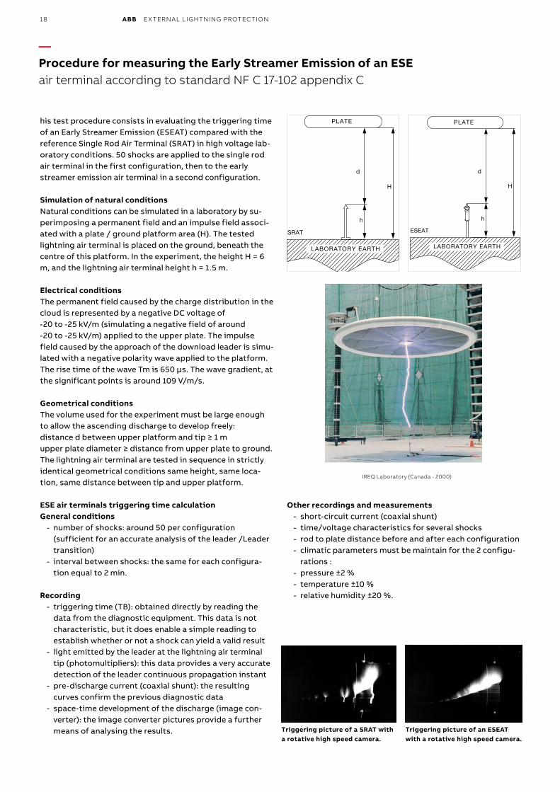
his test procedure consists in evaluating the triggering time of an Early Streamer Emission (ESEAT) compared with the reference Single Rod Air Terminal (SRAT) in high voltage lab-oratory conditions. 50 shocks are applied to the single rod air terminal in the first configuration, then to the early streamer emission air terminal in a second configuration.
Simulation of natural conditionsNatural conditions can be simulated in a laboratory by su-perimposing a permanent field and an impulse field associ-ated with a plate / ground platform area (H). The tested lightning air terminal is placed on the ground, beneath the centre of this platform. In the experiment, the height H = 6 m, and the lightning air terminal height h = 1.5 m.
Electrical conditionsThe permanent field caused by the charge distribution in the cloud is represented by a negative DC voltage of -20 to -25 kV/m (simulating a negative field of around -20 to -25 kV/m) applied to the upper plate. The impulse field caused by the approach of the download leader is simu-lated with a negative polarity wave applied to the platform. The rise time of the wave Tm is 650 µs. The wave gradient, at the significant points is around 109 V/m/s.
Geometrical conditionsThe volume used for the experiment must be large enough to allow the ascending discharge to develop freely:distance d between upper platform and tip ≥ 1 mupper plate diameter ≥ distance from upper plate to ground.The lightning air terminal are tested in sequence in strictly identical geometrical conditions same height, same loca-tion, same distance between tip and upper platform.
ESE air terminals triggering time calculationGeneral conditions
- number of shocks: around 50 per configuration (sufficient for an accurate analysis of the leader /Leader transition)
- interval between shocks: the same for each configura-tion equal to 2 min.
Recording - triggering time (TB): obtained directly by reading the
data from the diagnostic equipment. This data is not characteristic, but it does enable a simple reading to establish whether or not a shock can yield a valid result
- light emitted by the leader at the lightning air terminal tip (photomultipliers): this data provides a very accurate detection of the leader continuous propagation instant
- pre-discharge current (coaxial shunt): the resulting curves confirm the previous diagnostic data
- space-time development of the discharge (image con-verter): the image converter pictures provide a further means of analysing the results.
Other recordings and measurements - short-circuit current (coaxial shunt) - time/voltage characteristics for several shocks - rod to plate distance before and after each configuration - climatic parameters must be maintain for the 2 configu-
rations : - pressure ±2 % - temperature ±10 % - relative humidity ±20 %.
Triggering picture of a SRAT with a rotative high speed camera.
Triggering picture of an ESEAT with a rotative high speed camera.
IREQ Laboratory (Canada - 2000)
SRAT
LABORATORY EARTH
d
h
H
PLATE
d
h
H
ESEAT
LABORATORY EARTH
PLATE
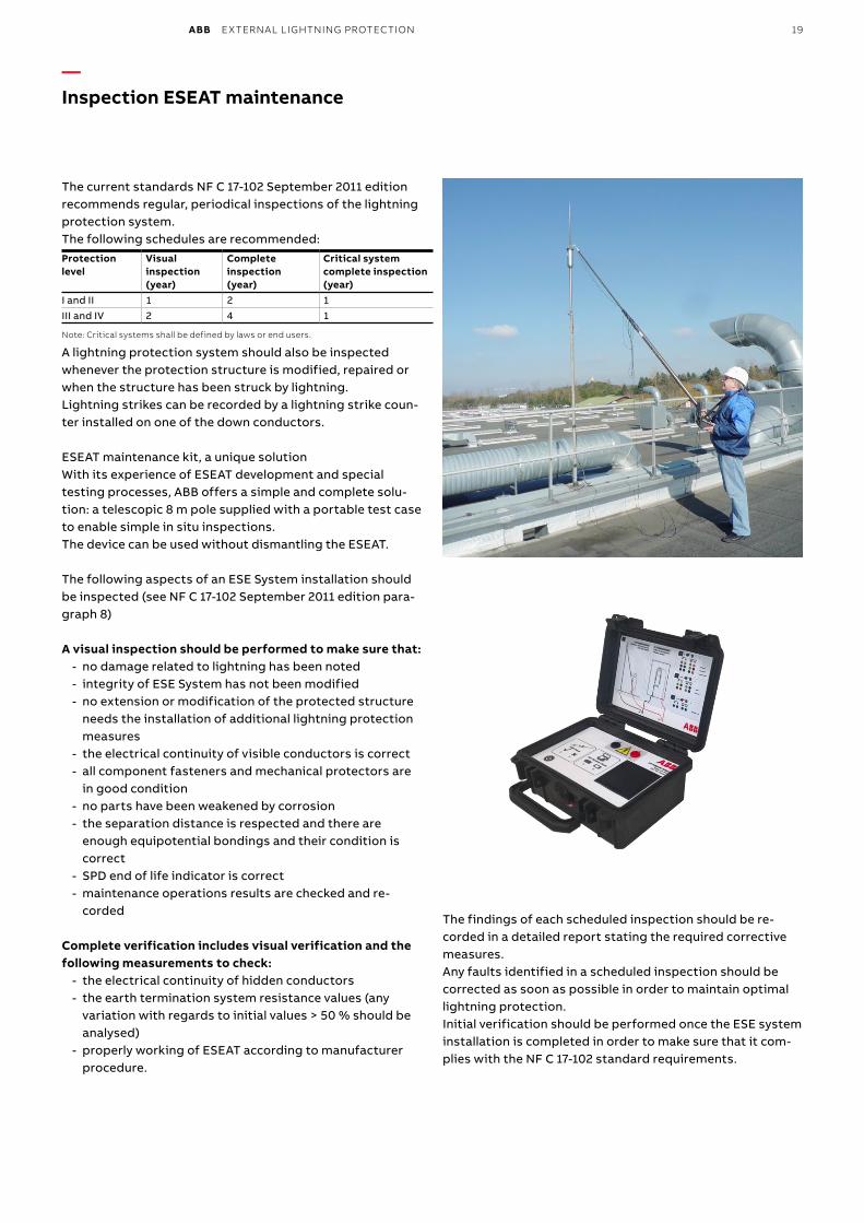
ABB EXTERNAL LIGHTNING PROTECTION 19
The current standards NF C 17-102 September 2011 edition recommends regular, periodical inspections of the lightning protection system. The following schedules are recommended: Protection level
Visual inspection (year)
Complete inspection (year)
Critical system complete inspection (year)
I and II 1 2 1III and IV 2 4 1
Note: Critical systems shall be defined by laws or end users.
A lightning protection system should also be inspected whenever the protection structure is modified, repaired or when the structure has been struck by lightning. Lightning strikes can be recorded by a lightning strike coun-ter installed on one of the down conductors.
ESEAT maintenance kit, a unique solutionWith its experience of ESEAT development and special testing processes, ABB offers a simple and complete solu-tion: a telescopic 8 m pole supplied with a portable test case to enable simple in situ inspections. The device can be used without dismantling the ESEAT.
The following aspects of an ESE System installation should be inspected (see NF C 17-102 September 2011 edition para-graph 8)
A visual inspection should be performed to make sure that: - no damage related to lightning has been noted - integrity of ESE System has not been modified - no extension or modification of the protected structure
needs the installation of additional lightning protection measures
- the electrical continuity of visible conductors is correct - all component fasteners and mechanical protectors are
in good condition - no parts have been weakened by corrosion - the separation distance is respected and there are
enough equipotential bondings and their condition is correct
- SPD end of life indicator is correct - maintenance operations results are checked and re-
corded
Complete verification includes visual verification and the following measurements to check:
- the electrical continuity of hidden conductors - the earth termination system resistance values (any
variation with regards to initial values > 50 % should be analysed)
- properly working of ESEAT according to manufacturer procedure.
The findings of each scheduled inspection should be re-corded in a detailed report stating the required corrective measures. Any faults identified in a scheduled inspection should be corrected as soon as possible in order to maintain optimal lightning protection. Initial verification should be performed once the ESE system installation is completed in order to make sure that it com-plies with the NF C 17-102 standard requirements.
— Inspection ESEAT maintenance

20 ABB EXTERNAL LIGHTNING PROTECTION
— Lightning protection technical studyOPR Designer software
ABB is happy to provide you with a complete new software in the field of lightning protection.With a very simple approach you can create your technical study in one click!
You can either draw, import file (AutoCAD, pictures…) and from that point get a complete bill of material (air termi-nals, down conductors, fixing accessories and earthing system), the positioning of the lightning protection sys-tem on the structure.The solution is given in a complete pdf file that includes :
- protected areas - lightning air terminals positioning - complete bill of material - detailed bill of material per building - catalogue pages for each component - test certificates
This software is so far available in English, French, Spanish, Russian and Lithuanian version.
You may download OPR designer at the following address: https://www.lowvoltage-tools.abb.com/download/opr/OPR_installer.exe
https://www.lowvoltage-tools.abb.com/download/opr/OPR_Installer.exe
Click on the button to install the application (26 Mb)A shortcut will be automatically added to your desktop to launch the application directly.
Require operating system or later verison : Windows (XP, Vista, Seven) or Apple (OSX) and Java
Magalie Gaber-Melek
Stamp
Magalie Gaber-Melek
Stamp
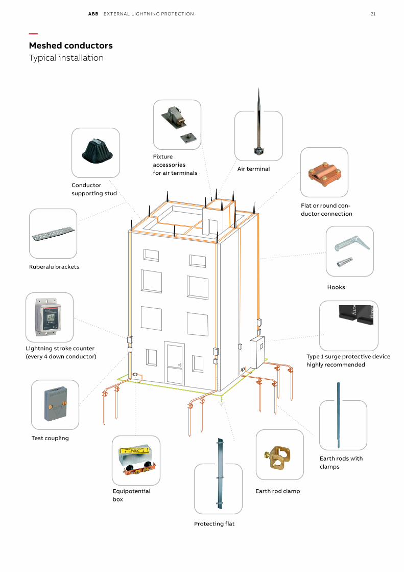
ABB EXTERNAL LIGHTNING PROTECTION 21
— Meshed conductorsTypical installation
Flat or round con-ductor connection
Hooks
Test coupling
Equipotential box
Lightning stroke counter (every 4 down conductor)
Conductor supporting stud
Fixture accessories for air terminals
Air terminal
Ruberalu brackets
Protecting flat
Earth rods with clamps
Earth rod clamp
Type 1 surge protective devicehighly recommended
Magalie Gaber-Melek
Stamp
22 ABB EXTERNAL LIGHTNING PROTECTION
— Down conductors
OverviewDown conductors should preferably be made with tin-plated red copper strips, 30 mm wide and 2 mm thick. Lightning is a high frequency current that flows along the periphery of the conductors. For a like cross-section, a flat conductor has a greater periphery. An exception to the above rule is buildings with aluminium cladding on which a copper down conductor might generate an electrolytic coupling phenomenon. Here a 30 x 3 mm aluminium strip should be used or bimetal connection. In some cases where it is impossible to fix the copper strip, a round Ø 8 mm tin-plated copper conductor. In the case where there is a need of mechanical movement of the down conductor use a 30 x 3 mm flexible tin-platted copper braid.
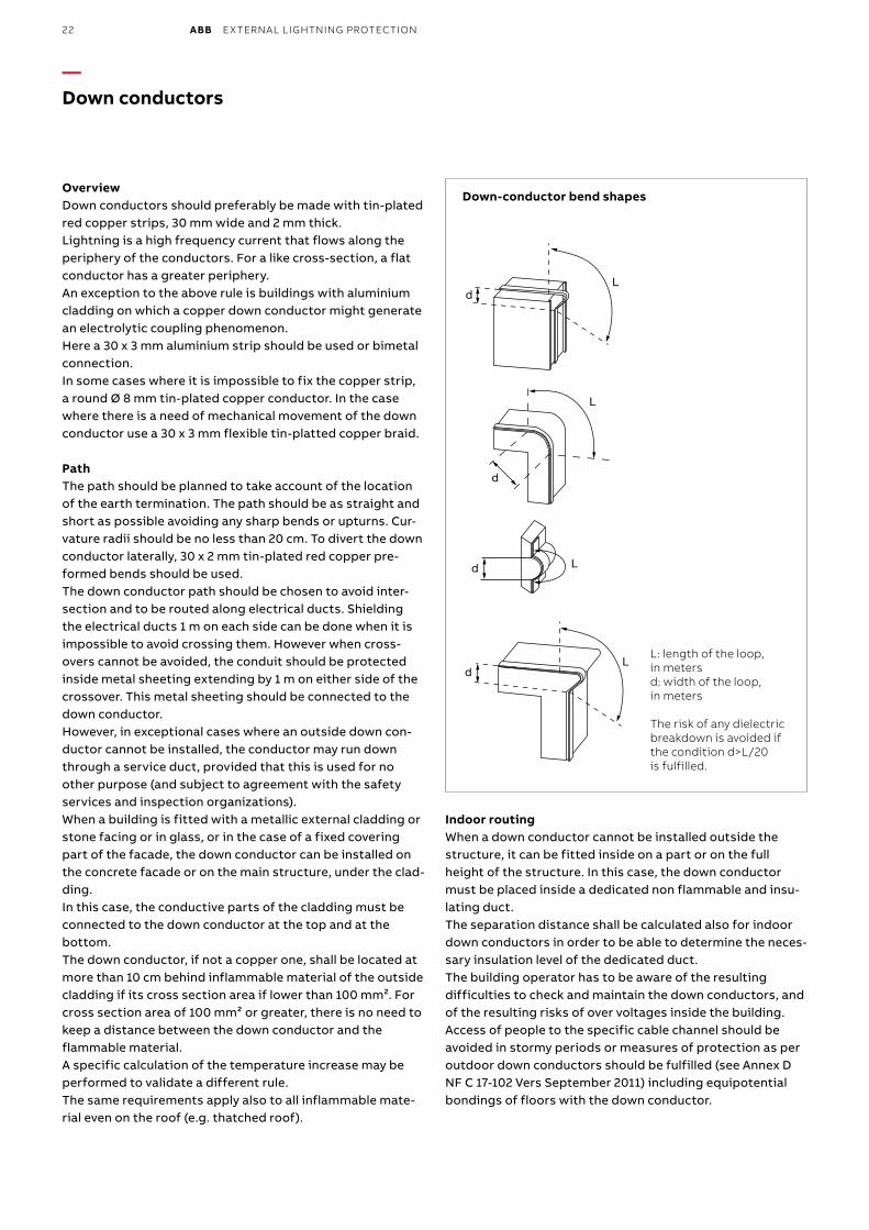
PathThe path should be planned to take account of the location of the earth termination. The path should be as straight and short as possible avoiding any sharp bends or upturns. Cur-vature radii should be no less than 20 cm. To divert the down conductor laterally, 30 x 2 mm tin-plated red copper pre-formed bends should be used. The down conductor path should be chosen to avoid inter-section and to be routed along electrical ducts. Shielding the electrical ducts 1 m on each side can be done when it is impossible to avoid crossing them. However when cross-overs cannot be avoided, the conduit should be protected inside metal sheeting extending by 1 m on either side of the crossover. This metal sheeting should be connected to the down conductor. However, in exceptional cases where an outside down con-ductor cannot be installed, the conductor may run down through a service duct, provided that this is used for no other purpose (and subject to agreement with the safety services and inspection organizations). When a building is fitted with a metallic external cladding or stone facing or in glass, or in the case of a fixed covering part of the facade, the down conductor can be installed on the concrete facade or on the main structure, under the clad-ding.In this case, the conductive parts of the cladding must be connected to the down conductor at the top and at the bottom.The down conductor, if not a copper one, shall be located at more than 10 cm behind inflammable material of the outside cladding if its cross section area if lower than 100 mm². For cross section area of 100 mm² or greater, there is no need to keep a distance between the down conductor and the flammable material.A specific calculation of the temperature increase may be performed to validate a different rule.The same requirements apply also to all inflammable mate-rial even on the roof (e.g. thatched roof).
Indoor routingWhen a down conductor cannot be installed outside the structure, it can be fitted inside on a part or on the full height of the structure. In this case, the down conductor must be placed inside a dedicated non flammable and insu-lating duct.The separation distance shall be calculated also for indoor down conductors in order to be able to determine the neces-sary insulation level of the dedicated duct.The building operator has to be aware of the resulting difficulties to check and maintain the down conductors, and of the resulting risks of over voltages inside the building.Access of people to the specific cable channel should be avoided in stormy periods or measures of protection as per outdoor down conductors should be fulfilled (see Annex D NF C 17-102 Vers September 2011) including equipotential bondings of floors with the down conductor.
L
d L
dL
dL
Ld
d
Down-conductor bend shapes
L: length of the loop, in metersd: width of the loop, in meters
The risk of any dielectric breakdown is avoided if the condition d>L/20 is fulfilled.
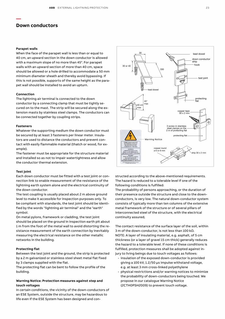
ABB EXTERNAL LIGHTNING PROTECTION 23
— Down conductors
Parapet wallsWhen the face of the parapet wall is less than or equal to 40 cm, an upward section in the down conductor is allowed with a maximum slope of no more than 45°. For parapet walls with an upward section of more than 40 cm, space should be allowed or a hole drilled to accommodate a 50 mm minimum diameter sheath and thereby avoid bypassing. If this is not possible, supports of the same height as the para-pet wall should be installed to avoid an upturn.
ConnectionThe lightning air terminal is connected to the down conductor by a connecting clamp that must be tightly se-cured on to the mast. The strip will be secured along the ex-tension masts by stainless steel clamps. The conductors can be connected together by coupling strips.
FastenersWhatever the supporting medium the down conductor must be secured by at least 3 fasteners per linear meter. Insula-tors are used to distance the conductors and prevent con-tact with easily flammable material (thatch or wood, for ex-ample). The fastener must be appropriate for the structure material and installed so as not to impair watertightness and allow the conductor thermal extension.
Test jointEach down conductor must be fitted with a test joint or con-nection link to enable measurement of the resistance of the lightning earth system alone and the electrical continuity of the down conductor. The test coupling is usually placed about 2 m above ground level to make it accessible for inspection purposes only. To be compliant with standards, the test joint should be identi-fied by the words "lightning air terminal" and the "earth" symbol. On metal pylons, framework or cladding, the test joint should be placed on the ground in inspection earth pit about 1 m from the foot of the metal wall to avoid distorting the re-sistance measurement of the earth connection by inevitably measuring the electrical resistance on the other metallic networks in the building. Protecting flatBetween the test joint and the ground, the strip is protected by a 2 m galvanized or stainless steel sheet metal flat fixed by 3 clamps supplied with the flat. The protecting flat can be bent to follow the profile of the building.
Warning Notice: Protection measures against step and touch voltagesIn certain conditions, the vicinity of the down-conductors of an ESE System, outside the structure, may be hazardous to life even if the ESE System has been designed and con-
structed according to the above-mentioned requirements.The hazard is reduced to a tolerable level if one of the following conditions is fulfilled:The probability of persons approaching, or the duration of their presence outside the structure and close to the down-conductors, is very low. The natural down-conductor system consists of typically more than ten columns of the extensive metal framework of the structure or of several pillars of interconnected steel of the structure, with the electrical continuity assured;
The contact resistance of the surface layer of the soil, within 3 m of the down-conductor, is not less than 100 kΩ.NOTE: A layer of insulating material, e.g. asphalt, of 5 cm thickness (or a layer of gravel 15 cm thick) generally reduces the hazard to a tolerable level. If none of these conditions is fulfilled, protection measures shall be adopted against in-jury to living beings due to touch voltages as follows:
- insulation of the exposed down-conductor is provided giving a 100 kV, 1.2/50 μs impulse withstand voltage, e.g. at least 3 mm cross-linked polyethylene
- physical restrictions and/or warning notices to minimize the probability of down-conductors being touched. We propose in our catalogue Warning Notice (2CTH0PSH2009) to prevent touch voltage.
strip 30 x 2 mm
copper roundø 6 or 8 mm
330
lead dowel
30 or 40
30
test joint
protectingat
hook
down conductor strip
lead dowel
copper tape30 x 2 mm
3 screw-in stainless steel clamps on the
2 m of protecting at
protecting at
40 cmmax
45°max
Warning Notice
24 ABB EXTERNAL LIGHTNING PROTECTION
— Down conductors
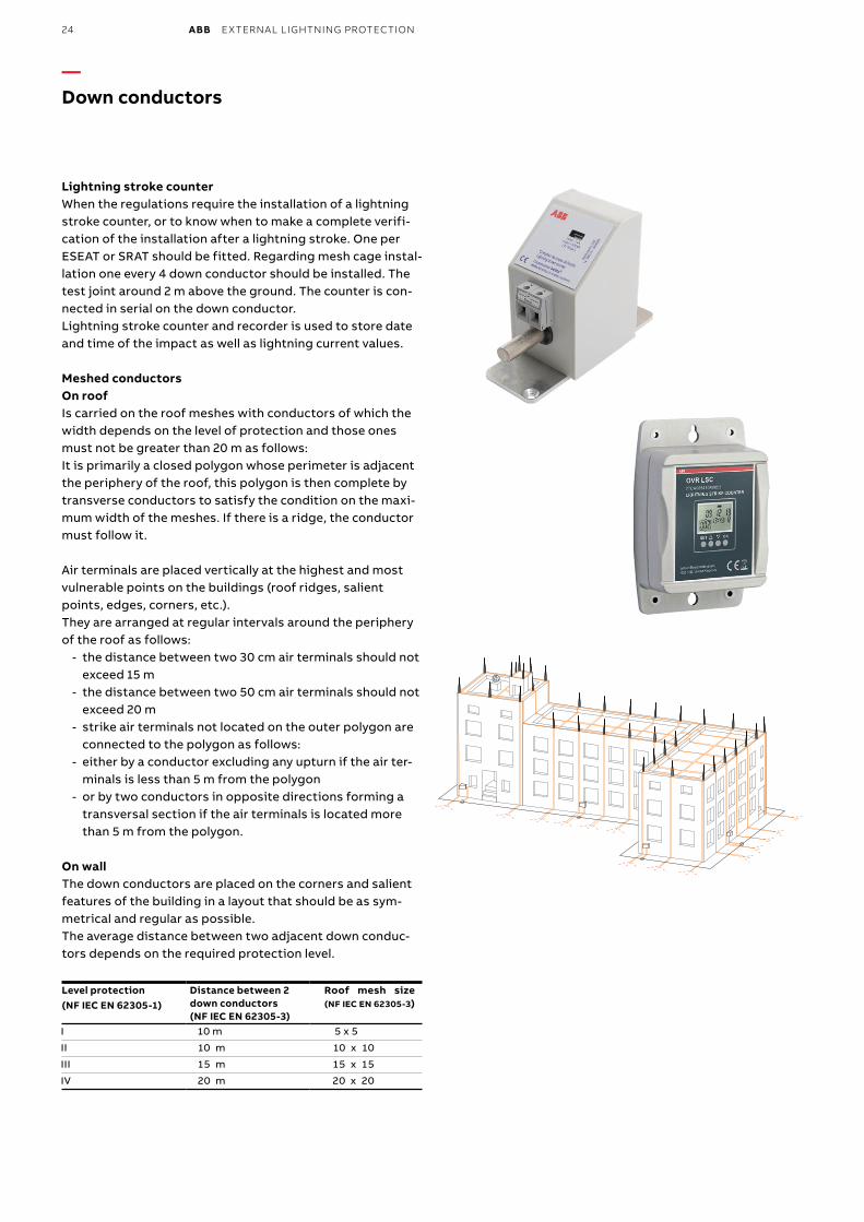
Lightning stroke counterWhen the regulations require the installation of a lightning stroke counter, or to know when to make a complete verifi-cation of the installation after a lightning stroke. One per ESEAT or SRAT should be fitted. Regarding mesh cage instal-lation one every 4 down conductor should be installed. The test joint around 2 m above the ground. The counter is con-nected in serial on the down conductor.Lightning stroke counter and recorder is used to store date and time of the impact as well as lightning current values.
Meshed conductorsOn roofIs carried on the roof meshes with conductors of which the width depends on the level of protection and those ones must not be greater than 20 m as follows:It is primarily a closed polygon whose perimeter is adjacent the periphery of the roof, this polygon is then complete by transverse conductors to satisfy the condition on the maxi-mum width of the meshes. If there is a ridge, the conductor must follow it.
Air terminals are placed vertically at the highest and most vulnerable points on the buildings (roof ridges, salient points, edges, corners, etc.). They are arranged at regular intervals around the periphery of the roof as follows:
- the distance between two 30 cm air terminals should not exceed 15 m
- the distance between two 50 cm air terminals should not exceed 20 m
- strike air terminals not located on the outer polygon are connected to the polygon as follows:
- either by a conductor excluding any upturn if the air ter-minals is less than 5 m from the polygon
- or by two conductors in opposite directions forming a transversal section if the air terminals is located more than 5 m from the polygon.
On wallThe down conductors are placed on the corners and salient features of the building in a layout that should be as sym-metrical and regular as possible. The average distance between two adjacent down conduc-tors depends on the required protection level.
Level protection (NF IEC EN 62305-1)
Distance between 2 down conductors (NF IEC EN 62305-3)
Roof mesh size (NF IEC EN 62305-3)
I 10 m 5 x 5
II 10 m 10 x 10
III 15 m 15 x 15
IV 20 m 20 x 20
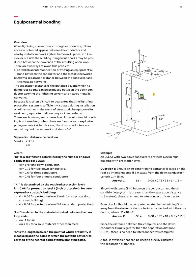
ABB EXTERNAL LIGHTNING PROTECTION 25
— Equipotential bonding
OverviewWhen lightning current flows through a conductor, differ-ences in potential appear between the conductor and nearby metallic networks (steel framework, pipes, etc.) in-side or outside the building. Dangerous sparks may be pro-duced between the two ends of the resulting open loop. There are two ways to avoid this problem:a) Establish an interconnection providing an equipotential
bond between the conductor and the metallic networksb) Allow a separation distance between the conductor and
the metallic networks.The separation distance is the distance beyond which no dangerous sparks can be produced between the down con-ductor carrying the lightning current and nearby metallic networks. Because it is often difficult to guarantee that the lightning protection system is sufficiently isolated during installation or will remain so in the event of structural changes, on-site work, etc., equipotential bonding is often preferred. There are, however, some cases in which equipotential bond-ing is not used (e.g. when there are flammable or explosive piping net-works). In this case, the down conductors are routed beyond the separation distance "s".
Separation distance calculationS (m) = ki.kc.L km
where:"kc" is a coefficient determined by the number of down conductors per ESEAT:
- kc = 1 for one down conductor, - kc = 0.75 for two down conductors, - kc = 0.6 for three conductors, - kc = 0.41 for four or more conductors. -
" ki " is determined by the required protection level: ki = 0.08 for protection level 1 (high protection), for very exposed or strategic buildings
- ki = 0.06 for protection level 2 (reinforced protection, exposed building)
- ki = 0.04 for protection level 3 & 4 (standard protection)
"km" is related to the material situated between the two loop ends:
- km : 1 for air - km = 0.5 for a solid material other than metal
"L" is the length between the point at which proximity is measured and the point at which the metallic network is earthed or the nearest equipotential bonding point.
ExampleAn ESEAT with two down conductors protects a 20 m high building with protection level I.
Question 1: Should an air conditioning extractor located on the roof be interconnected if 3 m away from the down conductor? Length L1 = 25 m. Answer 1: S1 = 0.08 x 0.75 x 25 / 1 = 1.5 m Since the distance (3 m) between the conductor and the air-conditioning system is greater than the separation distance (1.5 meters), there is no need to interconnect this extractor.
Question 2 : Should the computer located in the building 3 m away from the down conductor be interconnected with the con-ductor, where L2 = 10 m? Answer 2: S2 = 0.08 x 0.75 x 10 / 0.5 = 1.2 m Since the distance between the computer and the down conductor (3 m) is greater than the separation distance (1.2 m), there is no need to interconnect this computer.
A tool is available that can be used to quickly calculate the separation distances.
S1
L1
L2
S2
air cooling system
earth bar
26 ABB EXTERNAL LIGHTNING PROTECTION
— Equipotential bonding
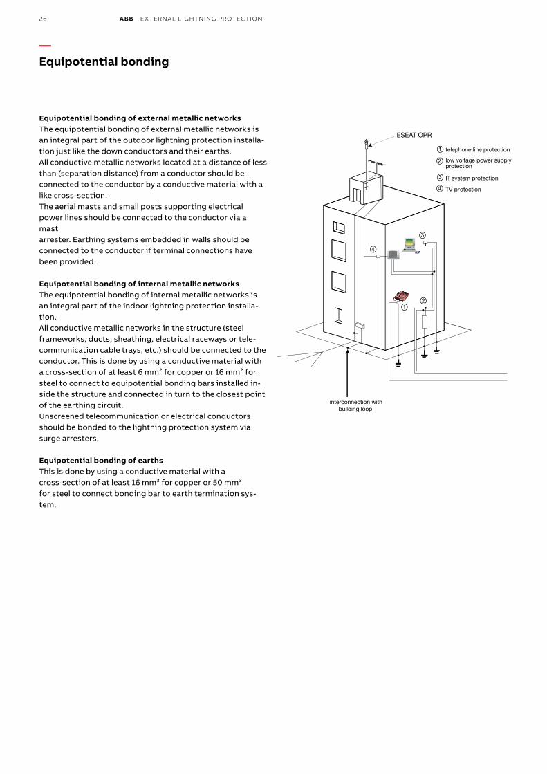
Equipotential bonding of external metallic networksThe equipotential bonding of external metallic networks is an integral part of the outdoor lightning protection installa-tion just like the down conductors and their earths. All conductive metallic networks located at a distance of less than (separation distance) from a conductor should be connected to the conductor by a conductive material with a like cross-section. The aerial masts and small posts supporting electrical power lines should be connected to the conductor via a mast arrester. Earthing systems embedded in walls should be connected to the conductor if terminal connections have been provided.
Equipotential bonding of internal metallic networksThe equipotential bonding of internal metallic networks is an integral part of the indoor lightning protection installa-tion. All conductive metallic networks in the structure (steel frameworks, ducts, sheathing, electrical raceways or tele-communication cable trays, etc.) should be connected to the conductor. This is done by using a conductive material with a cross-section of at least 6 mm² for copper or 16 mm² for steel to connect to equipotential bonding bars installed in-side the structure and connected in turn to the closest point of the earthing circuit. Unscreened telecommunication or electrical conductors should be bonded to the lightning protection system via surge arresters.
Equipotential bonding of earthsThis is done by using a conductive material with a cross-section of at least 16 mm² for copper or 50 mm² for steel to connect bonding bar to earth termination sys-tem.
interconnection with building loop
1
1
2
2
3
3
telephone line protection
low voltage power supplyprotection
IT system protection
4
4
TV protection
ESEAT OPR
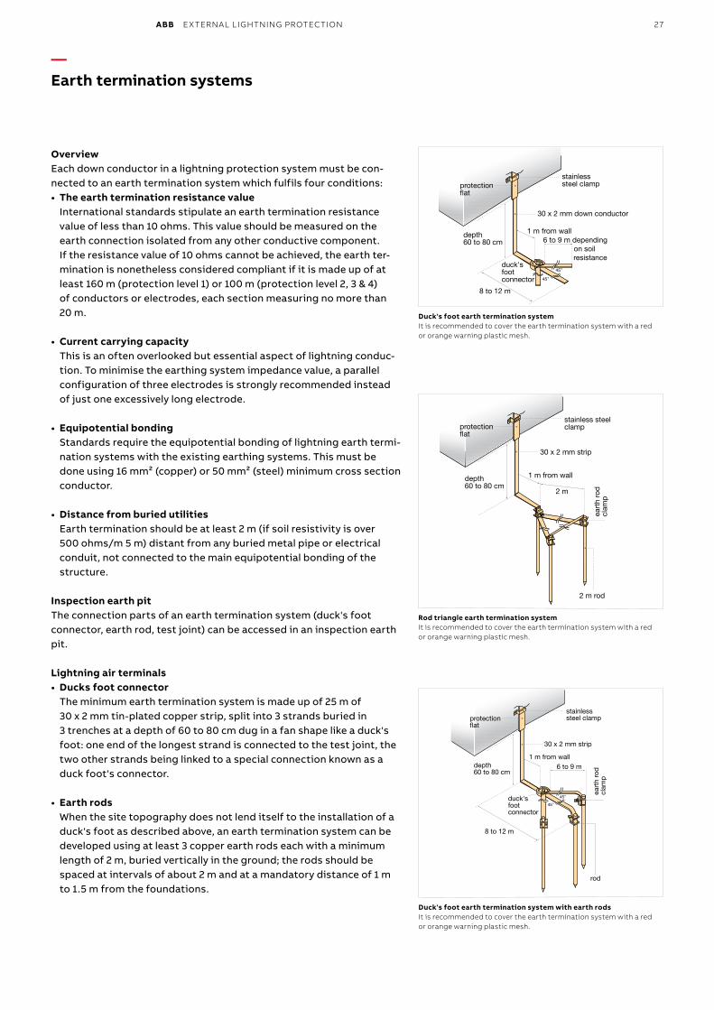
ABB EXTERNAL LIGHTNING PROTECTION 27
— Earth termination systems
OverviewEach down conductor in a lightning protection system must be con-nected to an earth termination system which fulfils four conditions: • The earth termination resistance value
International standards stipulate an earth termination resistance value of less than 10 ohms. This value should be measured on the earth connection isolated from any other conductive component. If the resistance value of 10 ohms cannot be achieved, the earth ter-mination is nonetheless considered compliant if it is made up of at least 160 m (protection level 1) or 100 m (protection level 2, 3 & 4) of conductors or electrodes, each section measuring no more than 20 m.
• Current carrying capacity This is an often overlooked but essential aspect of lightning conduc-tion. To minimise the earthing system impedance value, a parallel configuration of three electrodes is strongly recommended instead of just one excessively long electrode.
• Equipotential bonding Standards require the equipotential bonding of lightning earth termi-nation systems with the existing earthing systems. This must be done using 16 mm² (copper) or 50 mm² (steel) minimum cross section conductor.
• Distance from buried utilities Earth termination should be at least 2 m (if soil resistivity is over 500 ohms/m 5 m) distant from any buried metal pipe or electrical conduit, not connected to the main equipotential bonding of the structure.
Inspection earth pitThe connection parts of an earth termination system (duck's foot connector, earth rod, test joint) can be accessed in an inspection earth pit.
Lightning air terminals• Ducks foot connector
The minimum earth termination system is made up of 25 m of 30 x 2 mm tin-plated copper strip, split into 3 strands buried in 3 trenches at a depth of 60 to 80 cm dug in a fan shape like a duck's foot: one end of the longest strand is connected to the test joint, the two other strands being linked to a special connection known as a duck foot's connector.
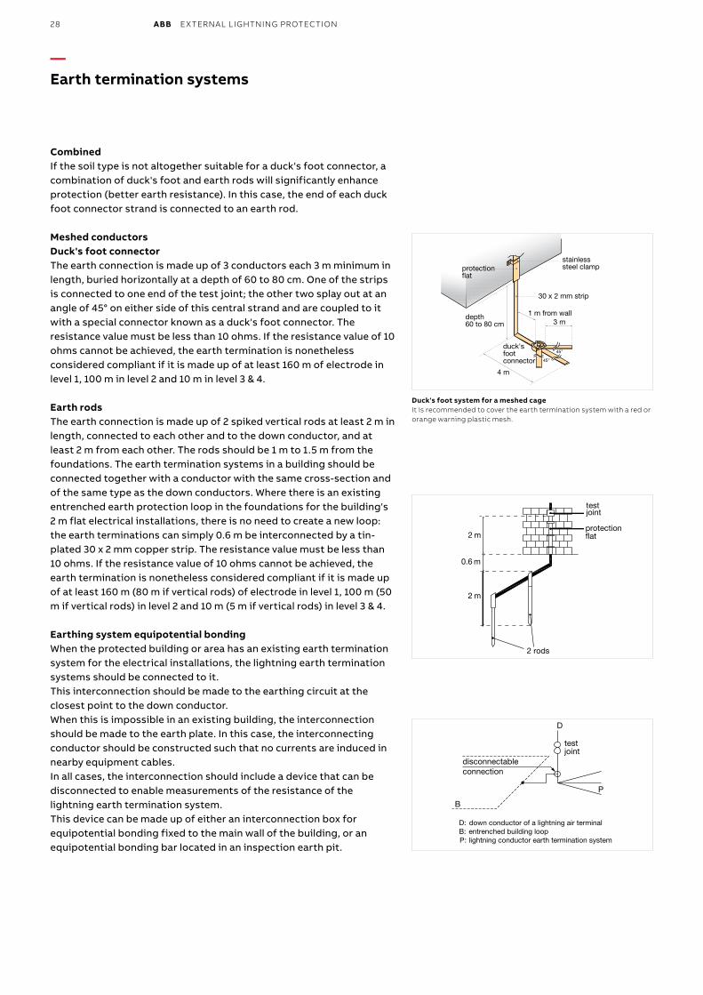
• Earth rods When the site topography does not lend itself to the installation of a duck's foot as described above, an earth termination system can be developed using at least 3 copper earth rods each with a minimum length of 2 m, buried vertically in the ground; the rods should be spaced at intervals of about 2 m and at a mandatory distance of 1 m to 1.5 m from the foundations.
protection at
30 x 2 mm down conductor
6 to 9 m depending on soil
resistance
1 m from walldepth 60 to 80 cm
8 to 12 m
stainless steel clamp
NB: the earth termination is covered by a red or orange warning grid
DUCK'S FOOT EARTH TERMINATION SYSTEM
duck's foot connector
Duck's foot earth termination systemIt is recommended to cover the earth termination system with a red or orange warning plastic mesh.
protection at
30 x 2 mm strip
2 m
1 m from walldepth 60 to 80 cm
stainless steel clamp
NB: the earth termination is covered by a red or orange warning grid 2 m rod
eart
h ro
d
clam
p
ROD TRIANGLE EARTH TERMINATION SYSTEM
Rod triangle earth termination systemIt is recommended to cover the earth termination system with a red or orange warning plastic mesh.
DUCK'S FOOT EARTH TERMINATION SYSTEM WITH EARTH RODS
protection at
30 x 2 mm strip
8 to 12 m
6 to 9 mdepth 60 to 80 cm
duck's foot connector
stainless steel clamp
NB: the earth termination is covered by a red or orange warning grid
rod
eart
h ro
d
clam
p
1 m from wall
Duck's foot earth termination system with earth rodsIt is recommended to cover the earth termination system with a red or orange warning plastic mesh.
28 ABB EXTERNAL LIGHTNING PROTECTION
— Earth termination systems
CombinedIf the soil type is not altogether suitable for a duck's foot connector, a combination of duck's foot and earth rods will significantly enhance protection (better earth resistance). In this case, the end of each duck foot connector strand is connected to an earth rod.
Meshed conductorsDuck's foot connector The earth connection is made up of 3 conductors each 3 m minimum in length, buried horizontally at a depth of 60 to 80 cm. One of the strips is connected to one end of the test joint; the other two splay out at an angle of 45° on either side of this central strand and are coupled to it with a special connector known as a duck's foot connector. The resistance value must be less than 10 ohms. If the resistance value of 10 ohms cannot be achieved, the earth termination is nonetheless considered compliant if it is made up of at least 160 m of electrode in level 1, 100 m in level 2 and 10 m in level 3 & 4.
Earth rodsThe earth connection is made up of 2 spiked vertical rods at least 2 m in length, connected to each other and to the down conductor, and at least 2 m from each other. The rods should be 1 m to 1.5 m from the foundations. The earth termination systems in a building should be connected together with a conductor with the same cross-section and of the same type as the down conductors. Where there is an existing entrenched earth protection loop in the foundations for the building's 2 m flat electrical installations, there is no need to create a new loop: the earth terminations can simply 0.6 m be interconnected by a tin-plated 30 x 2 mm copper strip. The resistance value must be less than 10 ohms. If the resistance value of 10 ohms cannot be achieved, the earth termination is nonetheless considered compliant if it is made up of at least 160 m (80 m if vertical rods) of electrode in level 1, 100 m (50 m if vertical rods) in level 2 and 10 m (5 m if vertical rods) in level 3 & 4.
Earthing system equipotential bondingWhen the protected building or area has an existing earth termination system for the electrical installations, the lightning earth termination systems should be connected to it. This interconnection should be made to the earthing circuit at the closest point to the down conductor. When this is impossible in an existing building, the interconnection should be made to the earth plate. In this case, the interconnecting conductor should be constructed such that no currents are induced in nearby equipment cables. In all cases, the interconnection should include a device that can be disconnected to enable measurements of the resistance of the lightning earth termination system. This device can be made up of either an interconnection box for equipotential bonding fixed to the main wall of the building, or an equipotential bonding bar located in an inspection earth pit.
Duck's foot system for a meshed cageIt is recommended to cover the earth termination system with a red or orange warning plastic mesh.
protection at
30 x 2 mm strip
3 m1 m from walldepth
60 to 80 cm
4 m
stainless steel clamp
NB: the earth termination is covered by a red or orange warning grid
DUCK'S FOOT SYSTEM FOR A MESHED CAGE
duck's foot connector
2 m
0.6 m
2 m
test joint
protection at
2 rods
D: down conductor of a lightning air terminalB: entrenched building loopP: lightning conductor earth termination system
test joint
disconnectableconnection
D
P
B
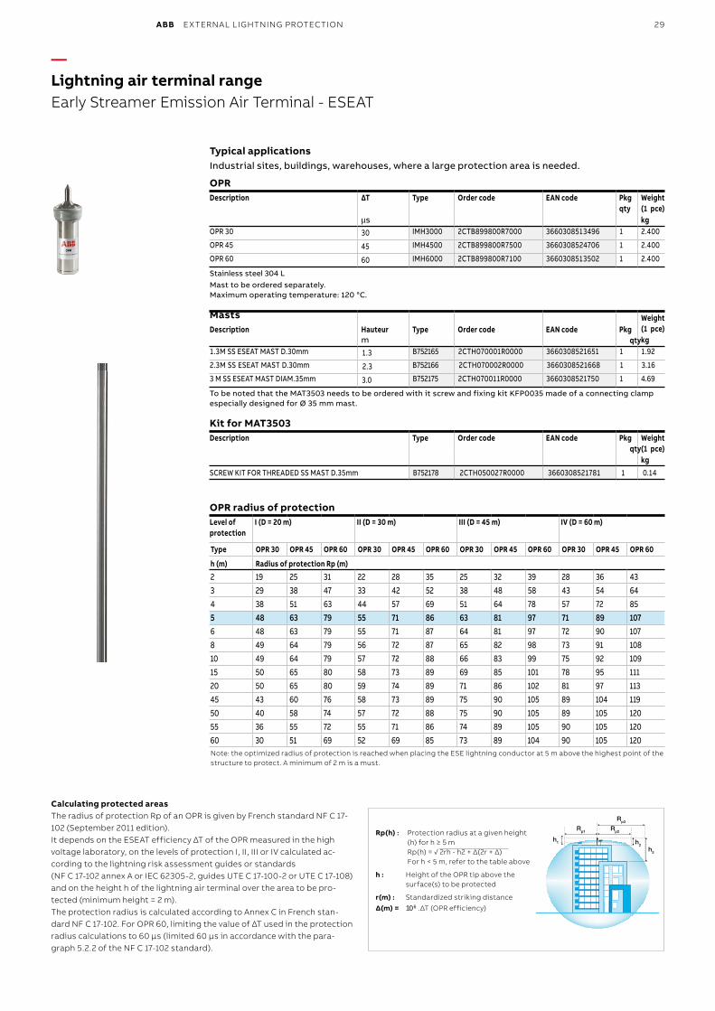
ABB EXTERNAL LIGHTNING PROTECTION 29
— Lightning air terminal rangeEarly Streamer Emission Air Terminal - ESEAT
Calculating protected areasThe radius of protection Rp of an OPR is given by French standard NF C 17-102 (September 2011 edition).It depends on the ESEAT efficiency ΔT of the OPR measured in the high voltage laboratory, on the levels of protection I, II, III or IV calculated ac-cording to the lightning risk assessment guides or standards (NF C 17-102 annex A or IEC 62305-2, guides UTE C 17-100-2 or UTE C 17-108) and on the height h of the lightning air terminal over the area to be pro-tected (minimum height = 2 m). The protection radius is calculated according to Annex C in French stan-dard NF C 17-102. For OPR 60, limiting the value of ΔT used in the protection radius calculations to 60 µs (limited 60 µs in accordance with the para-graph 5.2.2 of the NF C 17-102 standard).
Rp3
Rp2Rp1
h3
h1 h2
Rp(h) : Protection radius at a given height(h) for h ≥ 5 mRp(h) = √ 2rh - h2 + Δ(2r + Δ)For h < 5 m, refer to the table above
h : Height of the OPR tip above thesurface(s) to be protected
r(m) : Standardized striking distance
∆(m) = 106 .ΔT (OPR efficiency)
Typical applicationsIndustrial sites, buildings, warehouses, where a large protection area is needed.
OPRDescription ∆T Type Order code EAN code Pkg
qtyWeight(1 pce)
µs kg OPR 30 30 IMH3000 2CTB899800R7000 3660308513496 1 2.400
OPR 45 45 IMH4500 2CTB899800R7500 3660308524706 1 2.400
OPR 60 60 IMH6000 2CTB899800R7100 3660308513502 1 2.400
Stainless steel 304 LMast to be ordered separately.Maximum operating temperature: 120 °C.
MastsDescription Hauteur Type Order code EAN code Pkg
qty
Weight (1 pce)
m kg1.3M SS ESEAT MAST D.30mm 1.3 B752165 2CTH070001R0000 3660308521651 1 1.92
2.3M SS ESEAT MAST D.30mm 2.3 B752166 2CTH070002R0000 3660308521668 1 3.16
3 M SS ESEAT MAST DIAM.35mm 3.0 B752175 2CTH070011R0000 3660308521750 1 4.69
To be noted that the MAT3503 needs to be ordered with it screw and fixing kit KFP0035 made of a connecting clamp especially designed for Ø 35 mm mast.
Kit for MAT3503Description Type Order code EAN code Pkg
qtyWeight (1 pce)kg
SCREW KIT FOR THREADED SS MAST D.35mm B752178 2CTH050027R0000 3660308521781 1 0.14
OPR radius of protectionLevel of protection
I (D = 20 m) II (D = 30 m) III (D = 45 m) IV (D = 60 m)
Type OPR 30 OPR 45 OPR 60 OPR 30 OPR 45 OPR 60 OPR 30 OPR 45 OPR 60 OPR 30 OPR 45 OPR 60
h (m) Radius of protection Rp (m)2 19 25 31 22 28 35 25 32 39 28 36 433 29 38 47 33 42 52 38 48 58 43 54 644 38 51 63 44 57 69 51 64 78 57 72 855 48 63 79 55 71 86 63 81 97 71 89 1076 48 63 79 55 71 87 64 81 97 72 90 1078 49 64 79 56 72 87 65 82 98 73 91 10810 49 64 79 57 72 88 66 83 99 75 92 10915 50 65 80 58 73 89 69 85 101 78 95 11120 50 65 80 59 74 89 71 86 102 81 97 11345 43 60 76 58 73 89 75 90 105 89 104 11950 40 58 74 57 72 88 75 90 105 89 105 12055 36 55 72 55 71 86 74 89 105 90 105 12060 30 51 69 52 69 85 73 89 104 90 105 120Note: the optimized radius of protection is reached when placing the ESE lightning conductor at 5 m above the highest point of the structure to protect. A minimum of 2 m is a must.
30 ABB EXTERNAL LIGHTNING PROTECTION
—Lightning air terminal rangeSingle Rod Air Terminal - SRAT
α h
Rp
(B) 1
m
(C) 2
m
(A)
(D)
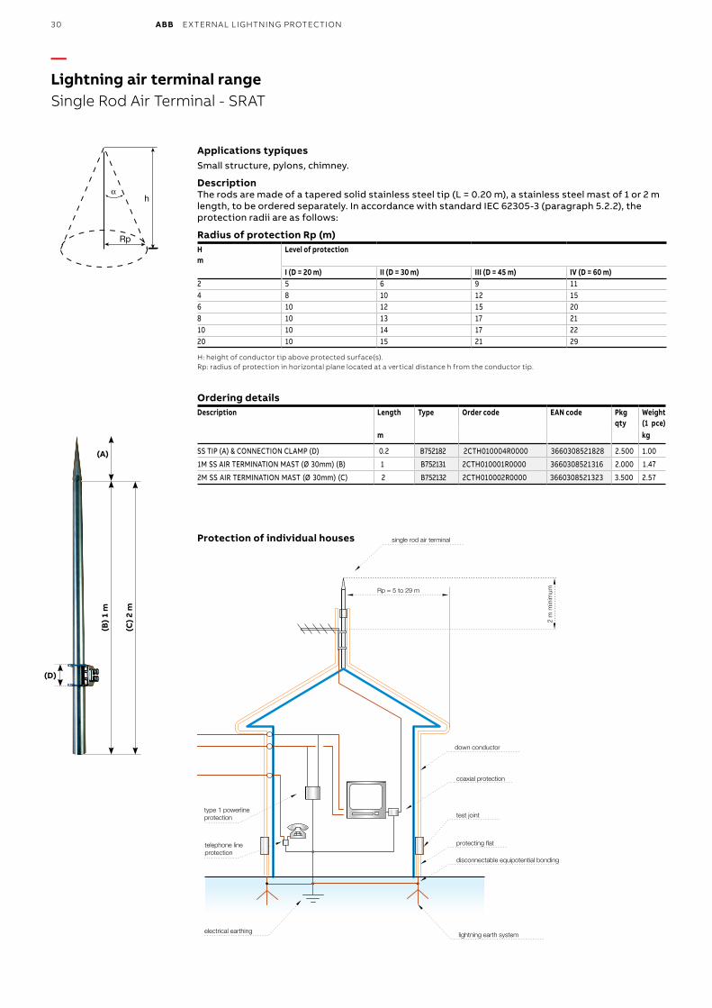
Protection of individual houses
PROTECTION OF INDIVIDUAL HOUSES
2 m
min
imum
protecting flat
disconnectable equipotential bonding
type 1 powerlineprotection
telephone lineprotection
coaxial protection
lightning earth system
test joint
down conductor
single rod air terminal
Rp = 5 to 29 m
electrical earthing
Applications typiquesSmall structure, pylons, chimney.
DescriptionThe rods are made of a tapered solid stainless steel tip (L = 0.20 m), a stainless steel mast of 1 or 2 m length, to be ordered separately. In accordance with standard IEC 62305-3 (paragraph 5.2.2), the protection radii are as follows:
Radius of protection Rp (m)Hm
Level of protection
I (D = 20 m) II (D = 30 m) III (D = 45 m) IV (D = 60 m)2 5 6 9 114 8 10 12 156 10 12 15 208 10 13 17 2110 10 14 17 2220 10 15 21 29
H: height of conductor tip above protected surface(s).Rp: radius of protection in horizontal plane located at a vertical distance h from the conductor tip.
Ordering detailsDescription Length Type Order code EAN code Pkg
qtyWeight (1 pce)
m kg
SS TIP (A) & CONNECTION CLAMP (D) 0.2 B752182 2CTH010004R0000 3660308521828 2.500 1.00
1M SS AIR TERMINATION MAST (Ø 30mm) (B) 1 B752131 2CTH010001R0000 3660308521316 2.000 1.47
2M SS AIR TERMINATION MAST (Ø 30mm) (C) 2 B752132 2CTH010002R0000 3660308521323 3.500 2.57
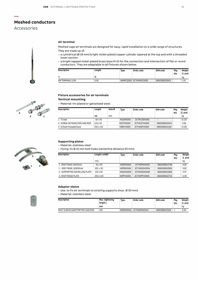
ABB EXTERNAL LIGHTNING PROTECTION 31
—Meshed conductorsAccessories
1 2
3
132
Air terminal
Meshed cage air terminals are designed for easy, rapid installation on a wide range of structures.They are made up of:
– a cylindrical (Ø 18 mm) bright nickel-plated copper cylinder tapered at the top and with a threaded lower section
– a bright tapped nickel-plated brass base M 10 for the connection and intersection of flat or round conductors. They are adaptable to all fixtures shown below.
Description Length Type Order code EAN code Pkg qty
Weight(1 pce)
m m kgAIR TERMINAL 0.5M 0.50 H0HPC5000 2CTH0HPC5000 3660308522603 1.43
Fixture accessories for air terminalsVertical mounting
– Material: tin-plated or galvanized steel.
Description Length Hole Ø Type Order code EAN code Pkg qty
Weight(1 pce)
cm mm kg
1 - To bed 50 x 50 HCSSH5001 2CTHCSSH5001 – 0.120
2 - SCREW-IN FIXING FOR CAGE ROD 120 x 50 HCSTH5002 2CTHCSTH5002 3660308524423 0.06
3 - S/Steel threaded base 250 x 120 H0EFH5003 2CTH0EFH5003 3660308522184 0.100
Supporting plates – Material: stainless steel – Fixing: 2x Ø 10 mm bolt holes (centerline distance 93 mm).
Description Length x width Type Order code EAN code Pkg qty
Adaptor sleeve – Use: to fix air terminals to existing supports (max. Ø 50 mm) – Material: stainless steel.
Description Max. tightening length L
Type Order code EAN code Pkg qty
Weight(1 pce)
mm kg
MAST SLEEVE ADAPTOR FOR CAGE ROD 100 H0HMA5010 2CTH0HMA5010 3660308522566 1 0.59
Weight (1 pce)
mm kg
1 - ROD FIXING 50X50mm 50 x 50 H0PSH5002 2CTH0PSH5002 3660308522795 0.08
1 - ROD FIXING 120X50mm 120 x 50 H0PSH5004 2CTH0SOH5004 3660308522801 0.20
2 - SUPPORTING SWIVELLING PLATE 120 x 50 H0SOH5006 2CTH0SOH5006 3660308522863 0.47
3 - ROOF RIDGE PLATE 250 x 120 H0PFH5000 2CTH0PFH5000 3660308522733 0.39
32 ABB EXTERNAL LIGHTNING PROTECTION
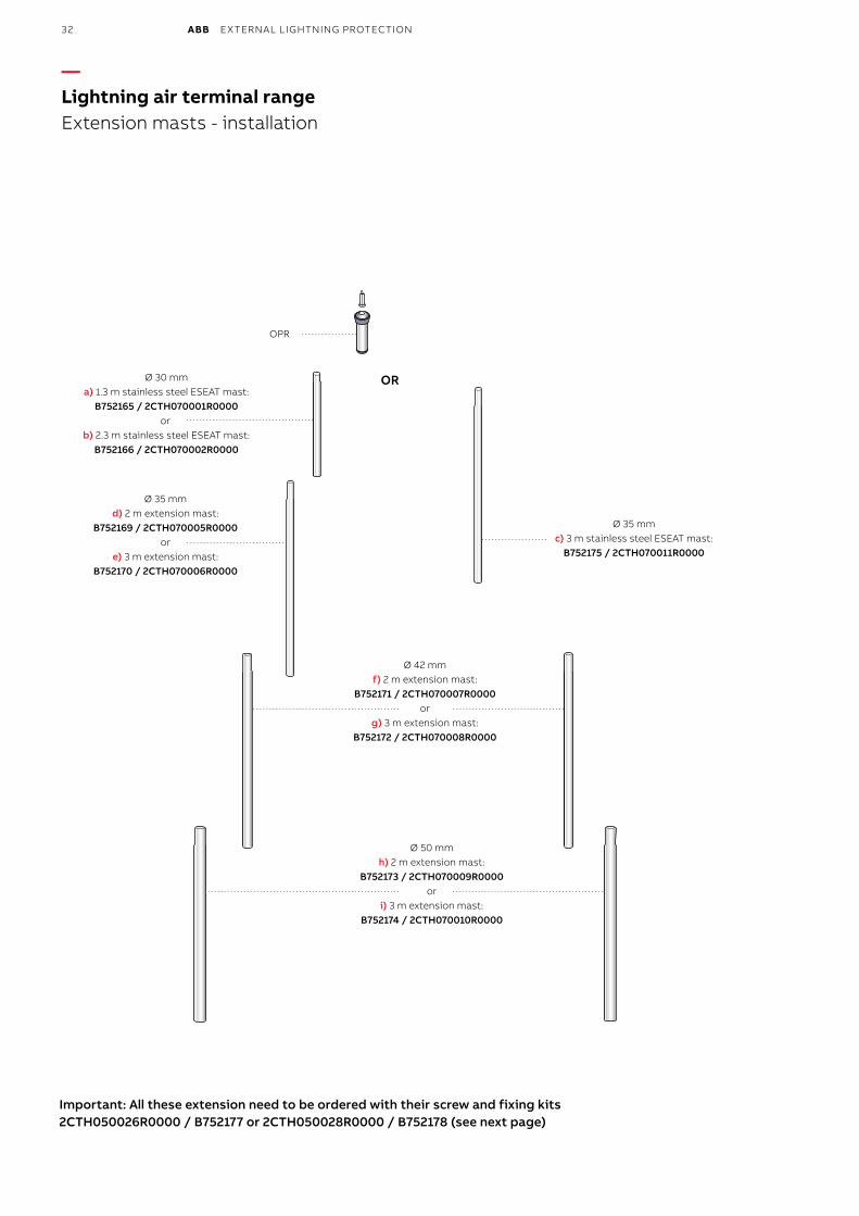
Important: All these extension need to be ordered with their screw and fixing kits 2CTH050026R0000 / B752177 or 2CTH050028R0000 / B752178 (see next page)
OPR
Ø 30 mm ORa) 1.3 m stainless steel ESEAT mast:
B752165 / 2CTH070001R0000or
b) 2.3 m stainless steel ESEAT mast: B752166 / 2CTH070002R0000
Ø 35 mmd) 2 m extension mast:
B752169 / 2CTH070005R0000or
e) 3 m extension mast: B752170 / 2CTH070006R0000
Ø 42 mmf) 2 m extension mast:
B752171 / 2CTH070007R0000 or
g) 3 m extension mast: B752172 / 2CTH070008R0000
Ø 50 mmh) 2 m extension mast:
B752173 / 2CTH070009R0000or
i) 3 m extension mast: B752174 / 2CTH070010R0000
Ø 35 mmc) 3 m stainless steel ESEAT mast:
B752175 / 2CTH070011R0000
—Lightning air terminal rangeExtension masts - installation
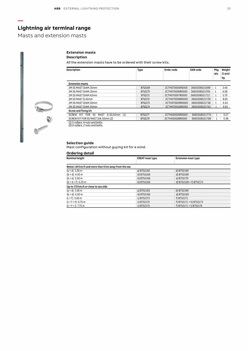
ABB EXTERNAL LIGHTNING PROTECTION 33
—Lightning air terminal rangeMasts and extension masts
Extension mastsDescriptionAll the extension masts have to be ordered with their screw kits.
Description Type Order code EAN code Pkg qty
Weight(1 pce)kg
Extension masts2M SS MAST DIAM.35mm B752169 2CTH070005R0000 3660308521699 1 3.403M SS MAST DIAM.35mm B752170 2CTH070006R0000 3660308521705 1 4.582M SS MAST DIAM.42mm B752171 2CTH070007R0000 3660308521712 1 5.793M SS MAST D.42mm B752172 2CTH070008R0000 3660308521729 1 8.652M SS MAST DIAM.50mm B752173 2CTH070009R0000 3660308521736 1 6.543M SS MAST DIAM.50mm B752174 2CTH070010R0000 3660308521743 1 9.93Screw and fixing kitSCREW KIT FOR SS MAST D.35/42mm (1) B752177 2CTH050026R0000 3660308521774 1 0.27 SCREW KIT FOR SS MAST DIA.50mm (2) B752179 2CTH050028R0000 3660308521798 1 0.38(1) 5 collars, 4 nuts and bolts.(2) 6 collars, 2 nuts and bolts.
Selection guideMast configuration without guying kit for a wind.
Ordering detail Nominal height ESEAT mast type Extension mast type
Below 140 km/h and more than 6 km away from the sea(a + d) 3.30 m a) B752165 d) B752169(b + d) 4.50 m b) B752166 d) B752169(b + e) 5.50 m b) B752166 e) B752170(b + d + f) 6.25 m b) B752166 d) B752169 + f) B752171
Up to 170 km/h or close to sea side(a + d) 3.30 m a) B752165 d) B752169(b + d) 4.50 m b) B752166 d) B752169(c + f) 5.00 m c) B752175 f) B752171(c + f + h) 6.75 m c) B752175 f) B752171 + h) B752173(c + f + i) 7.75 m c) B752175 f) B752171 + i) B752174
34 ABB EXTERNAL LIGHTNING PROTECTION
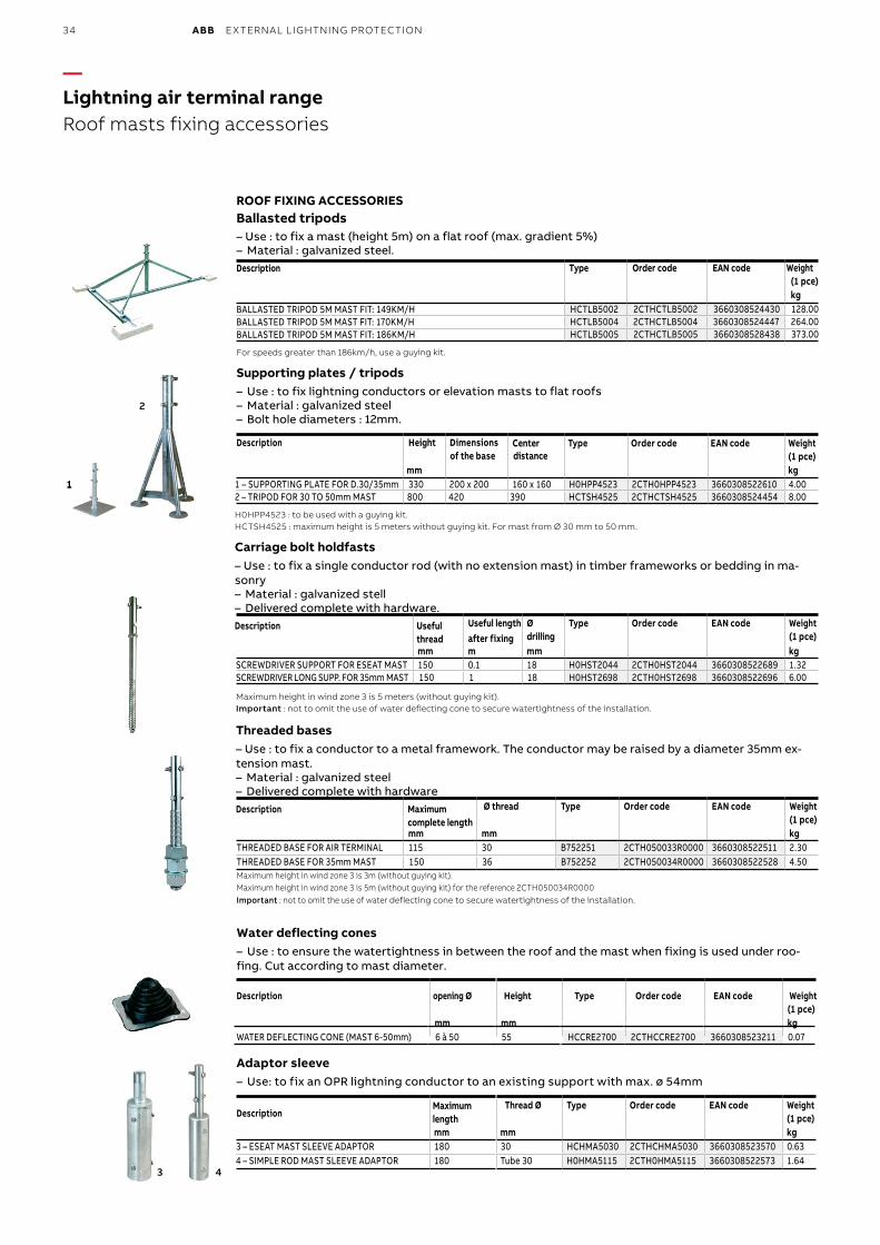
—Lightning air terminal rangeRoof masts fixing accessories
ROOF FIXING ACCESSORIESBallasted tripods– Use : to fix a mast (height 5m) on a flat roof (max. gradient 5%)– Material : galvanized steel.Description Type Order code EAN code Weight
(1 pce)kg
BALLASTED TRIPOD 5M MAST FIT: 149KM/H HCTLB5002 2CTHCTLB5002 3660308524430 128.00BALLASTED TRIPOD 5M MAST FIT: 170KM/H HCTLB5004 2CTHCTLB5004 3660308524447 264.00BALLASTED TRIPOD 5M MAST FIT: 186KM/H HCTLB5005 2CTHCTLB5005 3660308528438 373.00
For speeds greater than 186km/h, use a guying kit.
Supporting plates / tripods– Use : to fix lightning conductors or elevation masts to flat roofs– Material : galvanized steel– Bolt hole diameters : 12mm.
Description Height Dimensionsof the base distance
Center Type Order code EAN code Weight(1 pce)
mm kg1 – SUPPORTING PLATE FOR D.30/35mm 330 200 x 200 160 x 160 H0HPP4523 2CTH0HPP4523 3660308522610 4.00 2 – TRIPOD FOR 30 TO 50mm MAST 800 420 390 HCTSH4525 2CTHCTSH4525 3660308524454 8.00
H0HPP4523 : to be used with a guying kit.HCTSH4525 : maximum height is 5 meters without guying kit. For mast from Ø 30 mm to 50 mm.
Carriage bolt holdfasts– Use : to fix a single conductor rod (with no extension mast) in timber frameworks or bedding in ma-sonry– Material : galvanized stell– Delivered complete with hardware.Description Useful
threadUseful length after fixing
Ødrilling
Type Order code EAN code Weight(1 pce)
mm m mm kgSCREWDRIVER SUPPORT FOR ESEAT MAST 150 0.1 18 H0HST2044 2CTH0HST2044 3660308522689 1.32 SCREWDRIVER LONG SUPP. FOR 35mm MAST 150 1 18 H0HST2698 2CTH0HST2698 3660308522696 6.00
Maximum height in wind zone 3 is 5 meters (without guying kit).Important : not to omit the use of water deflecting cone to secure watertightness of the installation.
Threaded bases– Use : to fix a conductor to a metal framework. The conductor may be raised by a diameter 35mm ex-tension mast.– Material : galvanized steel– Delivered complete with hardwareDescription Maximum
complete lengthØ thread Type Order code EAN code Weight
(1 pce)mm mm kg
THREADED BASE FOR AIR TERMINAL 115 30 B752251 2CTH050033R0000 3660308522511 2.30 THREADED BASE FOR 35mm MAST 150 36 B752252 2CTH050034R0000 3660308522528 4.50 Maximum height in wind zone 3 is 3m (without guying kit).Maximum height in wind zone 3 is 5m (without guying kit) for the reference 2CTH050034R0000Important : not to omit the use of water deflecting cone to secure watertightness of the installation.
Water deflecting cones– Use : to ensure the watertightness in between the roof and the mast when fixing is used under roo-fing. Cut according to mast diameter.
Description opening Ø Height Type Order code EAN code Weight(1 pce)
mm mm kgWATER DEFLECTING CONE (MAST 6-50mm) 6 à 50 55 HCCRE2700 2CTHCCRE2700 3660308523211 0.07
Adaptor sleeve– Use: to fix an OPR lightning conductor to an existing support with max. ø 54mm
Description Thread Ø Type Order code EAN code Weight
(1 pce)mm mm kg
3 – ESEAT MAST SLEEVE ADAPTOR 180 30 HCHMA5030 2CTHCHMA5030 3660308523570 0.63 4 – SIMPLE ROD MAST SLEEVE ADAPTOR 180 Tube 30 H0HMA5115 2CTH0HMA5115 3660308522573 1.64
3 4
11
2
Maximum length
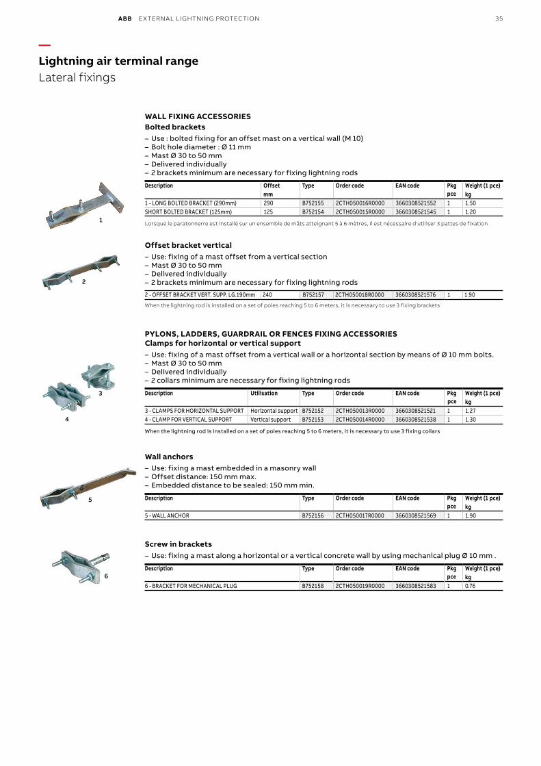
ABB EXTERNAL LIGHTNING PROTECTION 35
—Lightning air terminal rangeLateral fixings
1
3
4
2
5
6
WALL FIXING ACCESSORIESBolted brackets
– Use : bolted fixing for an offset mast on a vertical wall (M 10) – Bolt hole diameter : Ø 11 mm – Mast Ø 30 to 50 mm – Delivered individually – 2 brackets minimum are necessary for fixing lightning rods
Description Offset Type Order code EAN code Pkg pce
Weight (1 pce)mm kg
1 - LONG BOLTED BRACKET (290mm) 290 B752155 2CTH050016R0000 3660308521552 1 1.50 SHORT BOLTED BRACKET (125mm) 125 B752154 2CTH050015R0000 3660308521545 1 1.20
Lorsque le paratonnerre est installé sur un ensemble de mâts atteignant 5 à 6 mètres, il est nécessaire d'utiliser 3 pattes de fixation
Offset bracket vertical– Use: fixing of a mast offset from a vertical section– Mast Ø 30 to 50 mm– Delivered individually– 2 brackets minimum are necessary for fixing lightning rods
2 - OFFSET BRACKET VERT. SUPP. LG.190mm 240 B752157 2CTH050018R0000 3660308521576 1 1.90
When the lightning rod is installed on a set of poles reaching 5 to 6 meters, it is necessary to use 3 fixing brackets
PYLONS, LADDERS, GUARDRAIL OR FENCES FIXING ACCESSORIESClamps for horizontal or vertical support– Use: fixing of a mast offset from a vertical wall or a horizontal section by means of Ø 10 mm bolts.– Mast Ø 30 to 50 mm– Delivered individually– 2 collars minimum are necessary for fixing lightning rods
Description Utilisation Type Order code EAN code Pkg pce
Weight (1 pce)kg
3 - CLAMPS FOR HORIZONTAL SUPPORT Horizontal support B752152 2CTH050013R0000 3660308521521 1 1.274 - CLAMP FOR VERTICAL SUPPORT Vertical support B752153 2CTH050014R0000 3660308521538 1 1.30
When the lightning rod is installed on a set of poles reaching 5 to 6 meters, it is necessary to use 3 fixing collars
Wall anchors – Use: fixing a mast embedded in a masonry wall – Offset distance: 150 mm max. – Embedded distance to be sealed: 150 mm min.
Description Type Order code EAN code Pkg pce
Weight (1 pce)kg
5 - WALL ANCHOR B752156 2CTH050017R0000 3660308521569 1 1.90
Screw in brackets – Use: fixing a mast along a horizontal or a vertical concrete wall by using mechanical plug Ø 10 mm .
Description Type Order code EAN code Pkg pce
Weight (1 pce)kg
6 - BRACKET FOR MECHANICAL PLUG B752158 2CTH050019R0000 3660308521583 1 0.76
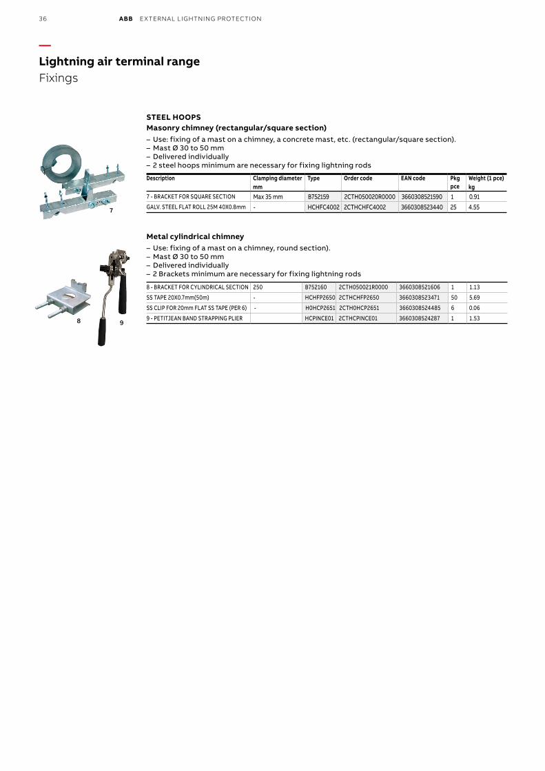
36 ABB EXTERNAL LIGHTNING PROTECTION
—Lightning air terminal rangeFixings
8
7
9
STEEL HOOPSMasonry chimney (rectangular/square section)
– Use: fixing of a mast on a chimney, a concrete mast, etc. (rectangular/square section). – Mast Ø 30 to 50 mm – Delivered individually – 2 steel hoops minimum are necessary for fixing lightning rods
Description Clamping diameter Type Order code EAN code Pkg pce
Weight (1 pce)mm kg
7 - BRACKET FOR SQUARE SECTION Max 35 mm B752159 2CTH050020R0000 3660308521590 1 0.91 GALV. STEEL FLAT ROLL 25M 40X0.8mm - HCHFC4002 2CTHCHFC4002 3660308523440 25 4.55
Metal cylindrical chimney– Use: fixing of a mast on a chimney, round section).– Mast Ø 30 to 50 mm– Delivered individually– 2 Brackets minimum are necessary for fixing lightning rods
8 - BRACKET FOR CYLINDRICAL SECTION 250 B752160 2CTH050021R0000 3660308521606 1 1.13
SS TAPE 20X0.7mm(50m) - HCHFP2650 2CTHCHFP2650 3660308523471 50 5.69
SS CLIP FOR 20mm FLAT SS TAPE (PER 6) - H0HCP2651 2CTH0HCP2651 3660308524485 6 0.06
9 - PETITJEAN BAND STRAPPING PLIER HCPINCE01 2CTHCPINCE01 3660308524287 1 1.53
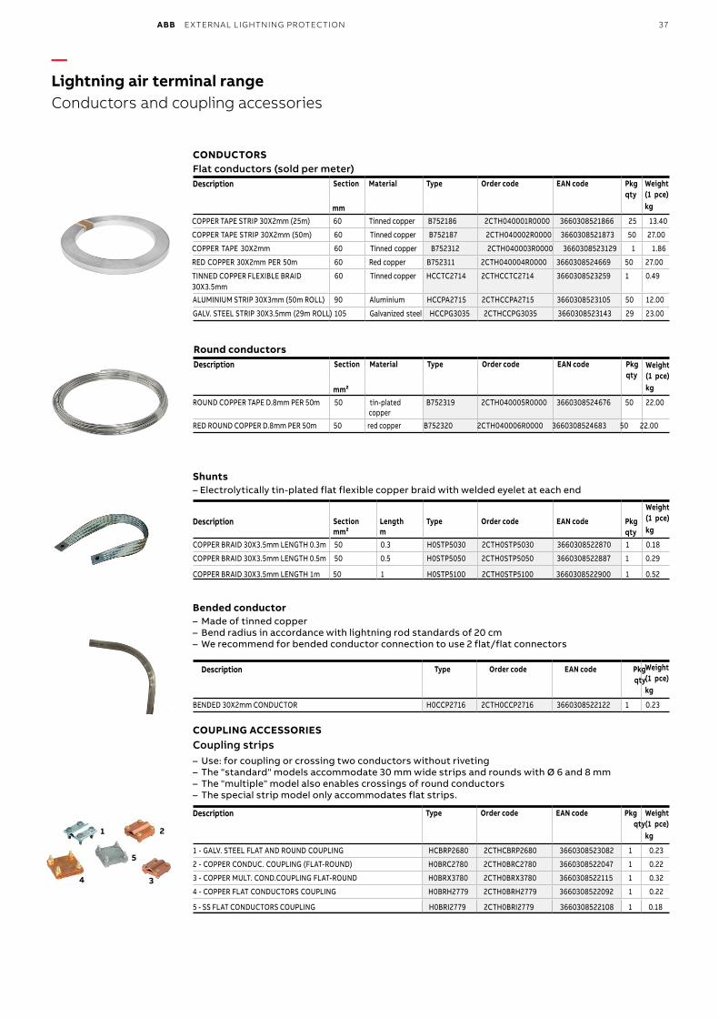
ABB EXTERNAL LIGHTNING PROTECTION 37
—Lightning air terminal rangeConductors and coupling accessories
1 2
4 3
5
CONDUCTORSFlat conductors (sold per meter)Description Section Material Type Order code EAN code Pkg
qtyWeight (1 pce)
mm kg
COPPER TAPE STRIP 30X2mm (25m) 60 Tinned copper B752186 2CTH040001R0000 3660308521866 25 13.40
COPPER TAPE STRIP 30X2mm (50m) 60 Tinned copper B752187 2CTH040002R0000 3660308521873 50 27.00
COPPER TAPE 30X2mm 60 Tinned copper B752312 2CTH040003R0000 3660308523129 1 1.86
RED COPPER 30X2mm PER 50m 60 Red copper B752311 2CTH040004R0000 3660308524669 50 27.00
TINNED COPPER FLEXIBLE BRAID30X3.5mm
60 Tinned copper HCCTC2714 2CTHCCTC2714 3660308523259 1 0.49
ALUMINIUM STRIP 30X3mm (50m ROLL) 90 Aluminium HCCPA2715 2CTHCCPA2715 3660308523105 50 12.00
GALV. STEEL STRIP 30X3.5mm (29m ROLL) 105 Galvanized steel HCCPG3035 2CTHCCPG3035 3660308523143 29 23.00
Round conductors Description Section Material Type Order code EAN code Pkg
qtyWeight(1 pce)
mm² kg
ROUND COPPER TAPE D.8mm PER 50m 50 tin-platedcopper
B752319 2CTH040005R0000 3660308524676 50 22.00
RED ROUND COPPER D.8mm PER 50m 50 red copper B752320 2CTH040006R0000 3660308524683 50 22.00
Shunts– Electrolytically tin-plated flat flexible copper braid with welded eyelet at each end
Description Section Length Type Order code EAN code Pkgqty
Weight (1 pce)
mm² m kg
COPPER BRAID 30X3.5mm LENGTH 0.3m 50 0.3 H0STP5030 2CTH0STP5030 3660308522870 1 0.18
COPPER BRAID 30X3.5mm LENGTH 0.5m 50 0.5 H0STP5050 2CTH0STP5050 3660308522887 1 0.29
COPPER BRAID 30X3.5mm LENGTH 1m 50 1 H0STP5100 2CTH0STP5100 3660308522900 1 0.52
Bended conductor– Made of tinned copper– Bend radius in accordance with lightning rod standards of 20 cm– We recommend for bended conductor connection to use 2 flat/flat connectors
Description Type Order code EAN code Pkg qty
Weight(1 pce)kg
BENDED 30X2mm CONDUCTOR H0CCP2716 2CTH0CCP2716 3660308522122 1 0.23
COUPLING ACCESSORIESCoupling strips– Use: for coupling or crossing two conductors without riveting– The "standard" models accommodate 30 mm wide strips and rounds with Ø 6 and 8 mm – The "multiple" model also enables crossings of round conductors– The special strip model only accommodates flat strips.
Description Type Order code EAN code Pkgqty
Weight(1 pce)kg
1 - GALV. STEEL FLAT AND ROUND COUPLING HCBRP2680 2CTHCBRP2680 3660308523082 1 0.23
2 - COPPER CONDUC. COUPLING (FLAT-ROUND) H0BRC2780 2CTH0BRC2780 3660308522047 1 0.22
3 - COPPER MULT. COND.COUPLING FLAT-ROUND H0BRX3780 2CTH0BRX3780 3660308522115 1 0.32
4 - COPPER FLAT CONDUCTORS COUPLING H0BRH2779 2CTH0BRH2779 3660308522092 1 0.22
5 - SS FLAT CONDUCTORS COUPLING H0BRI2779 2CTH0BRI2779 3660308522108 1 0.18
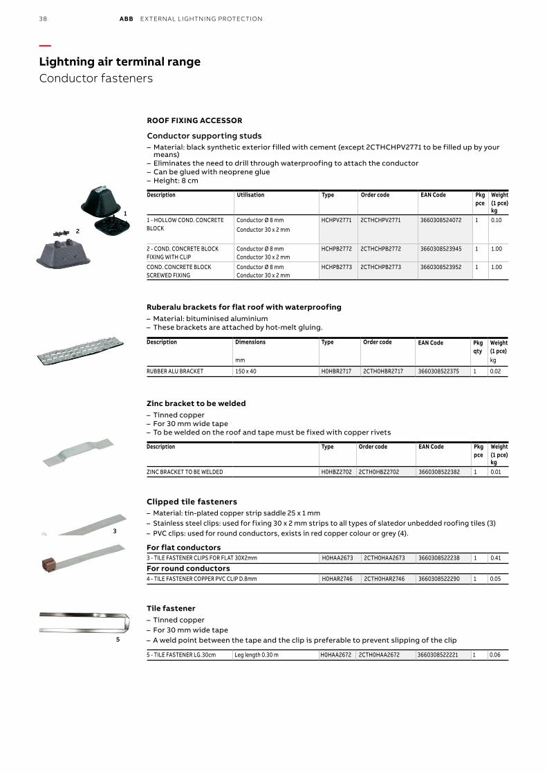
38 ABB EXTERNAL LIGHTNING PROTECTION
—Lightning air terminal rangeConductor fasteners
1
2
3
5
4
ROOF FIXING ACCESSOR
Conductor supporting studs – Material: black synthetic exterior filled with cement (except 2CTHCHPV2771 to be filled up by your means)
– Eliminates the need to drill through waterproofing to attach the conductor – Can be glued with neoprene glue – Height: 8 cm
Description Utilisation Type Order code EAN Code Pkg pce
Weight(1 pce)kg
1 - HOLLOW COND. CONCRETE BLOCK
Conductor Ø 8 mm Conductor 30 x 2 mm
HCHPV2771 2CTHCHPV2771 3660308524072 1 0.10
2 - COND. CONCRETE BLOCK FIXING WITH CLIP
Conductor Ø 8 mm Conductor 30 x 2 mm
HCHPB2772 2CTHCHPB2772 3660308523945 1 1.00
COND. CONCRETE BLOCK SCREWED FIXING
Conductor Ø 8 mm Conductor 30 x 2 mm
HCHPB2773 2CTHCHPB2773 3660308523952 1 1.00
Ruberalu brackets for flat roof with waterproofing – Material: bituminised aluminium – These brackets are attached by hot-melt gluing.
Description Dimensions Type Order code EAN Code Pkg qty
Weight(1 pce)
mm kg
RUBBER ALU BRACKET 150 x 40 H0HBR2717 2CTH0HBR2717 3660308522375 1 0.02
Zinc bracket to be welded – Tinned copper – For 30 mm wide tape – To be welded on the roof and tape must be fixed with copper rivets
Description Type Order code EAN Code Pkg pce
Weight(1 pce)kg
ZINC BRACKET TO BE WELDED H0HBZ2702 2CTH0HBZ2702 3660308522382 1 0.01
Clipped tile fasteners– Material: tin-plated copper strip saddle 25 x 1 mm– Stainless steel clips: used for fixing 30 x 2 mm strips to all types of slatedor unbedded roofing tiles (3)– PVC clips: used for round conductors, exists in red copper colour or grey (4).
For flat conductors3 - TILE FASTENER CLIPS FOR FLAT 30X2mm H0HAA2673 2CTH0HAA2673 3660308522238 1 0.41
For round conductors4 - TILE FASTENER COPPER PVC CLIP D.8mm H0HAR2746 2CTH0HAR2746 3660308522290 1 0.05
Tile fastener– Tinned copper– For 30 mm wide tape– A weld point between the tape and the clip is preferable to prevent slipping of the clip
5 - TILE FASTENER LG.30cm Leg length 0.30 m H0HAA2672 2CTH0HAA2672 3660308522221 1 0.06
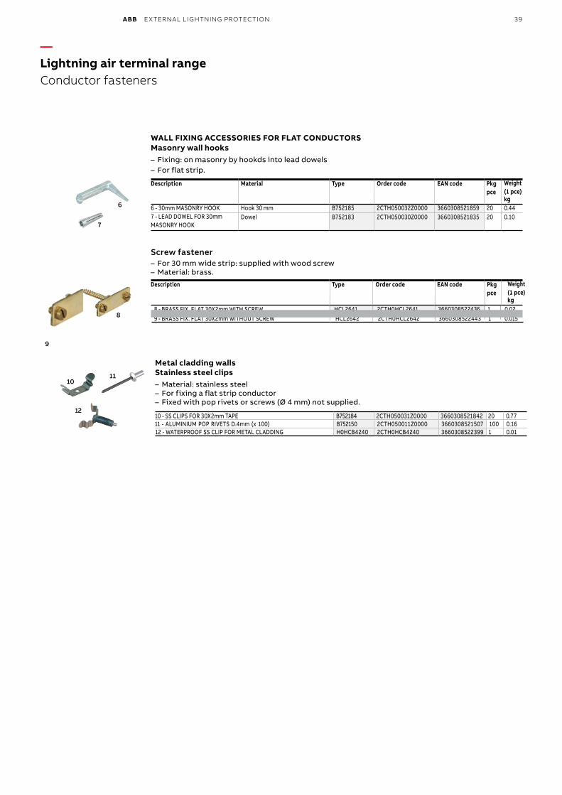
ABB EXTERNAL LIGHTNING PROTECTION 39
—Lightning air terminal rangeConductor fasteners
1011
12
6
7
WALL FIXING ACCESSORIES FOR FLAT CONDUCTORSMasonry wall hooks
– Fixing: on masonry by hookds into lead dowels – For flat strip.
Description Material Type Order code EAN code Pkg pce
Weight (1 pce)kg
6 - 30mm MASONRY HOOK Hook 30 mm B752185 2CTH050032Z0000 3660308521859 20 0.44 7 - LEAD DOWEL FOR 30mmMASONRY HOOK
Dowel B752183 2CTH050030Z0000 3660308521835 20 0.10
Screw fastener – For 30 mm wide strip: supplied with wood screw – Material: brass.
Description Type Order code EAN code Pkg pce
Weight (1 pce)kg
8 - BRASS FIX. FLAT 30X2mm WITH SCREW HCL2641 2CTH0HCL2641 3660308522436 1 0.029 - BRASS FIX. FLAT 30X2mm WITHOUT SCREW HCL2642 2CTH0HCL2642 3660308522443 1 0.015
Metal cladding wallsStainless steel clips– Material: stainless steel– For fixing a flat strip conductor– Fixed with pop rivets or screws (Ø 4 mm) not supplied.
10 - SS CLIPS FOR 30X2mm TAPE B752184 2CTH050031Z0000 3660308521842 20 0.7711 - ALUMINIUM POP RIVETS D.4mm (x 100) B752150 2CTH050011Z0000 3660308521507 100 0.1612 - WATERPROOF SS CLIP FOR METAL CLADDING H0HCB4240 2CTH0HCB4240 3660308522399 1 0.01
8
9
Magalie Gaber-Melek
Stamp
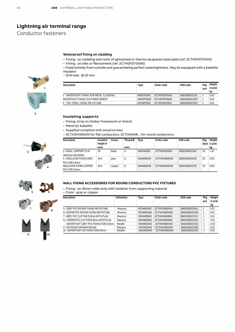
40 ABB EXTERNAL LIGHTNING PROTECTION
—Lightning air terminal rangeConductor fasteners
5 6
78
9 10
Waterproof fixing on cladding– Fixing : on cladding and roofs of galvanised or thermo-lacquered steel plate (ref. 2CTH0FDT0045)– Fixing : on tiles or fibrocement (ref. 2CTH0FDT0046)– Fixed entirely from outside and guaranteeing perfect watertightness. May be equipped with a bakelite insulator– Drill hole : Ø 10 mm
Description Type Order code EAN code Pkg pce
Weight (1 pce)kg
1 - WATERTIGHT FIXING FOR METAL CLADDING H0FDT0045 2CTH0FDT0045 3660308522191 1 0.03 WATERTIGHT FIXING TILE/FIBER CEMENT HOFDT0046 2CTH0FDT0046 3660308522207 1 0.03 2 - PVC COND. FIXING M8 FIXTURE HCHAP3001 2CTHCHAP3001 3660308523310 1 0.02
Insulating supports – Fixing: strip on timber framework or thatch – Material: bakelite – Supplied complete with wood screws – 2CTH0HIS6000 for flat conductors, 2CTH0HAR... for round conductors.
Description Insulator height H
Colour Thread Ø Type Order code EAN code Pkg(qty)
Weight(1 pce)
mm mm kg3 - INSUL. SUPPORT FLAT 30X2mm ON WOOD
35 black 6 H0HIS6000 2CTH0HIS6000 3660308522542 20 1.41
4 - INSULATED FIXING GREY PVC FOR D.8mm
36.4 grey 8 H0HAR2645 2CTH0HAR2645 3660308526236 20 0.06
INSULATED FIXING COPPER PVC FOR D.8mm
36.4 copper 8 H0HAR2646 2CTH0HAR2646 3660308522276 20 0.06
WALL FIXING ACCESSORIES FOR ROUND CONDUCTORS PVC FIXTURES
– Fixing : on 30mm wide strip with isolation from supporting material– Color : grey or copper.
Description Utilisation Type Order code EAN code Pkgpce
Weight (1 pce)kg
5 - GREY PVC ROUND FIXING M8 FIXTURE Masonry HCHAR2445 2CTHCHAR2445 3660308523341 1 0.01 6- COPPER PVC ROUND FIXING M8 FIXTURE Masonry HCHAR2446 2CTHCHAR2446 3660308523358 1 0.01 7 - GREY PVC CLIP FOR D.8mm WITH PLUG Masonry H0HAR2845 2CTH0HAR2845 3660308522313 1 0.018 - COPPER PVC CLIP FOR D.8mm WITH PLUG Masonry H0HAR2846 2CTH0HAR2846 3660308522320 1 0.01 - WATERTIGHT GREY PVC FIXING FOR D.8mm Metallic H0HAR2545 2CTH0HAR2545 3660308522252 1 0.02 9 - SS FIXING FOR 8MM ROUND Masonry HCHAR2945 2CTHCHAR2945 3660308523365 1 0.02 10 - WATERTIGHT SS FIXING FOR D.8mm Metallic H0HAR2945 2CTH0HAR2945 3660308522337 1 0.03
1
3
4
2
Bruno Roland
Rectangle
Magalie Gaber-Melek
Rectangle
Magalie Gaber-Melek
Rectangle
Magalie Gaber-Melek
Rectangle
Magalie Gaber-Melek
Rectangle
Magalie Gaber-Melek
Stamp
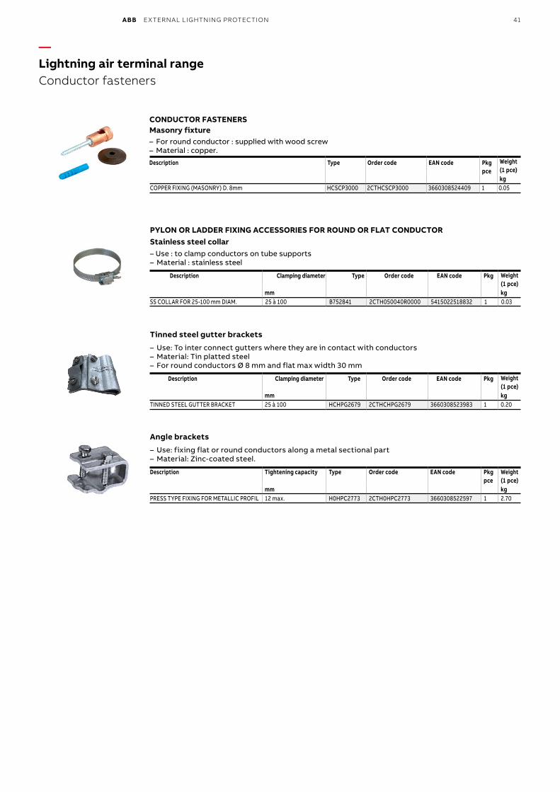
ABB EXTERNAL LIGHTNING PROTECTION 41
—Lightning air terminal rangeConductor fasteners
CONDUCTOR FASTENERSMasonry fixture– For round conductor : supplied with wood screw– Material : copper.
Description Type Order code EAN code Pkgpce
Weight (1 pce)kg
COPPER FIXING (MASONRY) D. 8mm HCSCP3000 2CTHCSCP3000 3660308524409 1 0.05
PYLON OR LADDER FIXING ACCESSORIES FOR ROUND OR FLAT CONDUCTOR Stainless steel collar– Use : to clamp conductors on tube supports– Material : stainless steel
Description Clamping diameter Type Order code EAN code Pkg Weight(1 pce)
mm kgSS COLLAR FOR 25-100 mm DIAM. 25 à 100 B752841 2CTH050040R0000 5415022518832 1 0.03
Tinned steel gutter brackets
– Use: To inter connect gutters where they are in contact with conductors – Material: Tin platted steel– For round conductors Ø 8 mm and flat max width 30 mm
Description Clamping diameter Type Order code EAN code Pkg Weight(1 pce)
mm kgTINNED STEEL GUTTER BRACKET 25 à 100 HCHPG2679 2CTHCHPG2679 3660308523983 1 0.20
Angle brackets
– Use: fixing flat or round conductors along a metal sectional part – Material: Zinc-coated steel.
Description Tightening capacity Type Order code EAN code Pkg pce
Weight(1 pce)
mm kgPRESS TYPE FIXING FOR METALLIC PROFIL 12 max. H0HPC2773 2CTH0HPC2773 3660308522597 1 2.70
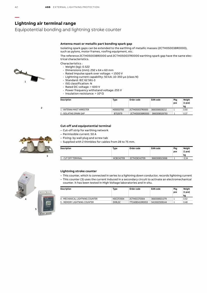
42 ABB EXTERNAL LIGHTNING PROTECTION
—Lightning air terminal rangeEquipotential bonding and lightning stroke counter
4
5
3
1
Antenna mast or metallic part bonding spark gapIsolating spark gaps can be extended to the earthing of metallic masses (2CTH050038R0000), such as pylons, motor frames, roofing equipment, etc.
The reference 2CTH050038R0000 and 2CTH050037R0000 earthing spark gap have the same elec-trical characteristics.
Characteristics : - Weight (kg): 0.522 - Dimensions (mm): 292 x 64 x 60 mm - Rated impulse spark over voltage: < 1500 V - Lightning current capability: 50 kA: 10-350 µs (class N) - Standard: IEC 62 561-3 - ISG classification: N - Rated DC voltage: > 600 V - Power frequency withstand voltage: 255 V - Insulation resistance: > 108 Ω
Description Type Order code EAN code Pkg pce
Weight (1 pce)kg
1 - ANTENNA MAST ARRESTER H05003700 2CTH050037R0000 3660308526212 1 0.50
2 - ISOLATING SPARK GAP B752679 2CTH050038R0000 3660308526793 1 0.37
Cut-off and equipotential terminal – Cut-off strip for earthing network – Permissible current: 50 A – Fixing: by wall plug and screw tab – Supplied with 2 thimbles for cables from 28 to 75 mm.
Description Type Order code EAN code Pkg pce
Weight (1 pce)kg
3 - CUT OFF TERMINAL HCBCH2709 2CTHCBCH2709 3660308523068 1 0.34
Lightning stroke counter – This counter, which is connected in series to a lightning down conductor, records lightning current – This counter (3) uses the current induced in a secondary circuit to activate an electromechanical counter. It has been tested in High Voltage laboratories and in situ.
Description Type Order code EAN code Pkg pce
Weight (1 pce)kg
4 - MECHANICAL LIGHTNING COUNTER H0CCF2004 2CTH0CCF2004 3660308521279 1 0.52 5 - MEMORY LIGHTNING COUNTER OVRLSC 7TCA085410R0053 5415022509144 1 0.48
2
Magalie Gaber-Melek
Stamp
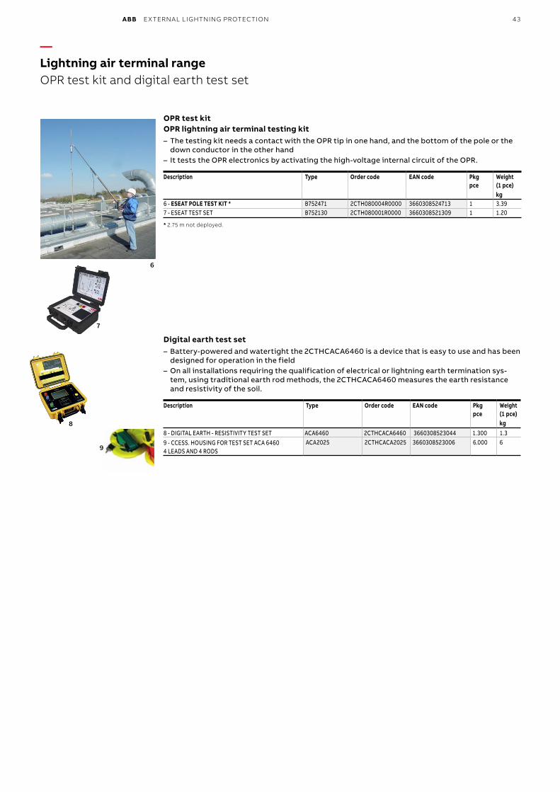
ABB EXTERNAL LIGHTNING PROTECTION 43
8
—Lightning air terminal rangeOPR test kit and digital earth test set
6
7
OPR test kitOPR lightning air terminal testing kit
– The testing kit needs a contact with the OPR tip in one hand, and the bottom of the pole or the down conductor in the other hand
– It tests the OPR electronics by activating the high-voltage internal circuit of the OPR.
Description Type Order code EAN code Pkg pce
Weight(1 pce)kg
6 - ESEAT POLE TEST KIT * B752471 2CTH080004R0000 3660308524713 1 3.397 - ESEAT TEST SET B752130 2CTH080001R0000 3660308521309 1 1.20
* 2.75 m not deployed.
Digital earth test set – Battery-powered and watertight the 2CTHCACA6460 is a device that is easy to use and has been designed for operation in the field
– On all installations requiring the qualification of electrical or lightning earth termination sys-tem, using traditional earth rod methods, the 2CTHCACA6460 measures the earth resistance and resistivity of the soil.
Description Type Order code EAN code Pkg pce
Weight (1 pce)kg
8 - DIGITAL EARTH - RESISTIVITY TEST SET ACA6460 2CTHCACA6460 3660308523044 1.300 1.3 9 - CCESS. HOUSING FOR TEST SET ACA 64604 LEADS AND 4 RODS
ACA2025 2CTHCACA2025 3660308523006 6.000 69
Magalie Gaber-Melek
Stamp
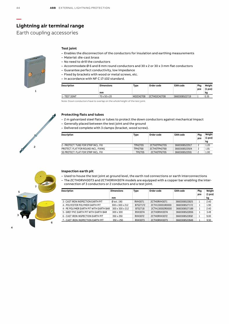
44 ABB EXTERNAL LIGHTNING PROTECTION
—Lightning air terminal rangeEarth coupling accessories
3
6
5
7
Test joint – Enables the disconnection of the conductors for insulation and earthing measurements – Material: die-cast brass – No need to drill the conductors – Accommodate Ø 6 and 8 mm round conductors and 30 x 2 or 30 x 3 mm flat conductors – Guarantee perfect conductivity, low impedance – Fixed by brackets with wood or metal screws, etc. – In accordance with NF C 17-102 standard.
Description Dimensions Type Order code EAN code Pkg pce
Weight (1 pce)
mm kg 70 x 50 x 20 H0JCH2708 2CTH0JCH2708 3660308522719 1 0.35
Note: Down conductors have to overlap on the whole height of the test joint.
Protecting flats and tubes – 2 m galvanized steel flats or tubes to protect the down conductors against mechanical impact – Generally placed between the test joint and the ground – Delivered complete with 3 clamps (bracket, wood screw).
Description Type Order code EAN code Pkg pce
Inspection earth pit – Used to house the test joint at ground level, the earth rod connections or earth interconnections – The 2CTH0RVH3073 and 2CTH0RVH3074 models are equipped with a copper bar enabling the inter-connection of 3 conductors or 2 conductors and a test joint.
Description Dimensions Type Order code EAN code Pkg pce
Weight (1 pce)
mm kg3 - CAST IRON INSPECTION EARTH PIT Ø ext. 190 RVH3071 2CTH0RVH3071 3660308522825 1 2.40 4 - POLYESTER POLYMER EARTH PIT 300 x 300 x 212 B7527172 2CTH130001R0000 3660308527172 1 1.90 4 - PE POLYMER EARTH PIT WITH EARTH BAR 300 x 300 x 212 B752718 2CTH130002R0000 3660308527189 1 2.40 5 - GREY PVC EARTH PIT WITH EARTH BAR 300 x 300 RVH3074 2CTH0RVH3074 3660308522856 1 3.496 - CAST IRON INSPECTION EARTH PIT 350 x 250 RVH3072 2CTH0RVH3072 3660308522832 1 9.007 - CAST IRON INSPECTION EARTH PIT 350 x 250 RVH3073 2CTH0RVH3073 3660308522849 1 9.50
2
1
1 - TEST JOINT
Weight (1 pce)kg
2 - PROTECT. TUBE FOR STRIP INCL. FIX TPH2705 2CTH0TPH2705 3660308522917 2 1.20 PROTECT. FLAT FOR ROUND INCL. FIXING TPH2768 2CTH0TPH2768 3660308522924 2 1.81 SS PROTECT. FLAT FOR STRIP INCL. FIX TPI2705 2CTH0TPI2705 3660308522931 2 1.00
4
Magalie Gaber-Melek
Rectangle
Magalie Gaber-Melek
Stamp
Magalie Gaber-Melek
Rectangle
Magalie Gaber-Melek
Rectangle
Magalie Gaber-Melek
Stamp
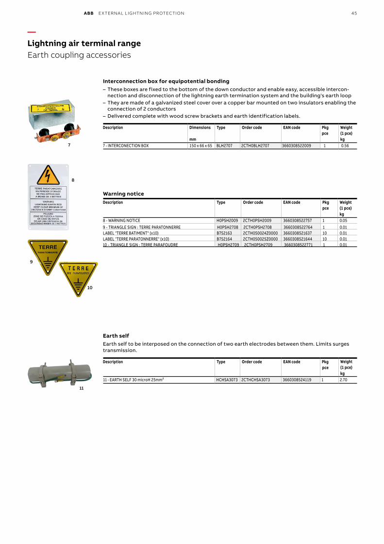
ABB EXTERNAL LIGHTNING PROTECTION 45
—Lightning air terminal rangeEarth coupling accessories
8
7
9
10
11
Earth selfEarth self to be interposed on the connection of two earth electrodes between them. Limits surges transmission.
Description Type Order code EAN code Pkg pce
Weight (1 pce)kg
11 - EARTH SELF 30 microH 25mm² HCHSA3073 2CTHCHSA3073 3660308524119 1 2.70
Warning noticeDescription Type Order code EAN code Pkg
pceWeight (1 pce)kg
8 - WARNING NOTICE H0PSH2009 2CTH0PSH2009 3660308522757 1 0.05 9 - TRIANGLE SIGN : TERRE PARATONNERRE H0PSH2708 2CTH0PSH2708 3660308522764 1 0.01 LABEL "TERRE BATIMENT" (x10) B752163 2CTH050024Z0000 3660308521637 10 0.01 LABEL "TERRE PARATONNERRE" (x10) B752164 2CTH050025Z0000 3660308521644 10 0.01 10 - TRIANGLE SIGN : TERRE PARAFOUDRE H0PSH2709 2CTH0PSH2709 3660308522771 1 0.01
Interconnection box for equipotential bonding – These boxes are fixed to the bottom of the down conductor and enable easy, accessible intercon-nection and disconnection of the lightning earth termination system and the building's earth loop
– They are made of a galvanized steel cover over a copper bar mounted on two insulators enabling the connection of 2 conductors
– Delivered complete with wood screw brackets and earth identification labels.
Description Dimensions Type Order code EAN code Pkg pce
Weight (1 pce)
mm kg7 - INTERCONECTION BOX 150 x 66 x 65 BLH2707 2CTH0BLH2707 3660308522009 1 0.56
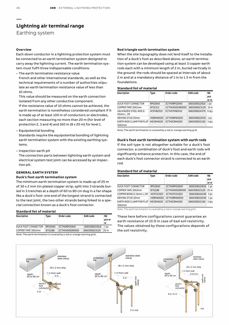
46 ABB EXTERNAL LIGHTNING PROTECTION
—Lightning air terminal rangeEarthing system
protection at
30 x 2 mm strip
3 m1 m from walldepth
60 to 80 cm
4 m
stainless steel clamp
NB: the earth termination is covered by a red or orange warning grid
DUCK'S FOOT SYSTEM FOR A MESHED CAGE
duck's foot connector
protection at
30 x 2 mm strip
2 m
1 m from walldepth 60 to 80 cm
stainless steel clamp
NB: the earth termination is covered by a red or orange warning grid 2 m rod
eart
h ro
d
clam
p
ROD TRIANGLE EARTH TERMINATION SYSTEM DUCK'S FOOT EARTH TERMINATION
SYSTEM WITH EARTH RODS
protection at
30 x 2 mm strip
8 to 12 m
6 to 9 mdepth 60 to 80 cm
duck's foot connector
stainless steel clamp
NB: the earth termination is covered by a red or orange warning grid
rod
eart
h ro
d
clam
p
1 m from wall
OverviewEach down conductor in a lightning protection system must be connected to an earth termination system designed to carry away the lightning current. The earth termination sys-tem must fulfil three indispensable conditions:
– The earth termination resistance valueFrench and other international standards, as well as the technical requirements of a number of authorities stipu-late an earth termination resistance value of less than10 ohms.This value should be measured on the earth connection isolated from any other conductive component.If the resistance value of 10 ohms cannot be achieved, the earth termination is nonetheless considered compliant if it is made up of at least 100 m of conductors or electrodes, each section measuring no more than 20 m (for level of protection 2, 3 and 4) and 160 m (8 x 20 m) for level 1.
– Equipotential bondingStandards require the equipotential bonding of lightningearth termination system with the existing earthing sys-tems.
– Inspection earth pitThe connection parts between lightning earth system andelectrical system test joint can be accessed by an inspec-tion pit.
GENERAL EARTH SYSTEMDuck's foot earth termination systemThe minimum earth termination system is made up of 25 mof 30 x 2 mm tin-plated copper strip, split into 3 strands bur-ied in 3 trenches at a depth of 60 to 80 cm dug in a fan shape like a duck's foot: one end of the longest strand is connected to the test joint, the two other strands being linked to a spe-cial connection known as a duck's foot connector.
Standard list of materialDescription Type Order code EAN code Nb
pcs orm
DUCK FOOT CONNECTOR RPO2840 2CTH0RPO2840 3660308522818 1 pc COPPER TAPE 30X2mm B752186 2CTH040001R0000 3660308523129 25 m Note: The earth termination is covered by a red or orange warning grid.
Rod triangle earth termination systemWhen the site topography does not lend itself to the installa-tion of a duck's foot as described above, an earth termina-tion system can be developed using at least 3 copper earth rods each with a minimum length of 2 m, buried vertically in the ground: the rods should be spaced at intervals of about2 m and at a mandatory distance of 1 m to 1.5 m from the foundations.
Standard list of materialDescription Type Order code EAN code Nb
pcs or m
DUCK FOOT CONNECTOR RPO2840 2CTH0RPO2840 3660308522818 1 pc COPPER TAPE 30X2mm B752312 2CTH040003R0000 3660308523129 10 m GALVINIZED STEEL ROD D.20mm L. 1M
HCPVB2010 2CTHCPVB2010 3660308524379 6 qty
DRIVING STUD 20mm H0BMA0020 2CTH0BMA0020 3660308522030 1 pc EARTH ROD CLAMP FOR FLAT30X2mm
H0CRH4020 2CTH0CRH4020 3660308522160 3 qty
Note: The earth termination is covered by a red or orange warning grid.
Duck's foot earth termination system with earth rods If the soil type is not altogether suitable for a duck's foot connector, a combination of duck's foot and earth rods willsignificantly enhance protection. In this case, the end of each duck's foot connector strand is connected to an earth rod.
Standard list of materialDescription Type Order code EAN code Nb
pcs or m
DUCK FOOT CONNECTOR RPO2840 2CTH0RPO2840 3660308522818 1 pcCOPPER TAPE 30X2mm B752186 2CTH040001R0000 3660308523129 25 mCOPPER BOND D.19mm L.2M HCPCS1920 2CTHCPCS1920 3660308524249 3 pcDRIVING STUD 20mm H0BMA0020 2CTH0BMA0020 3660308522030 1 pcEARTH ROD CLAMP FOR FLAT30X2mm
H0CRH4020 2CTH0CRH4020 3660308522160 3 qty
Note: The earth termination is covered by a red or orange warning grid.
These here before configurations cannot guarantee an earth resistance of 10 Ω in case of bad soil resistivity. The values obtained by these configurations depends of the soil resistivity.
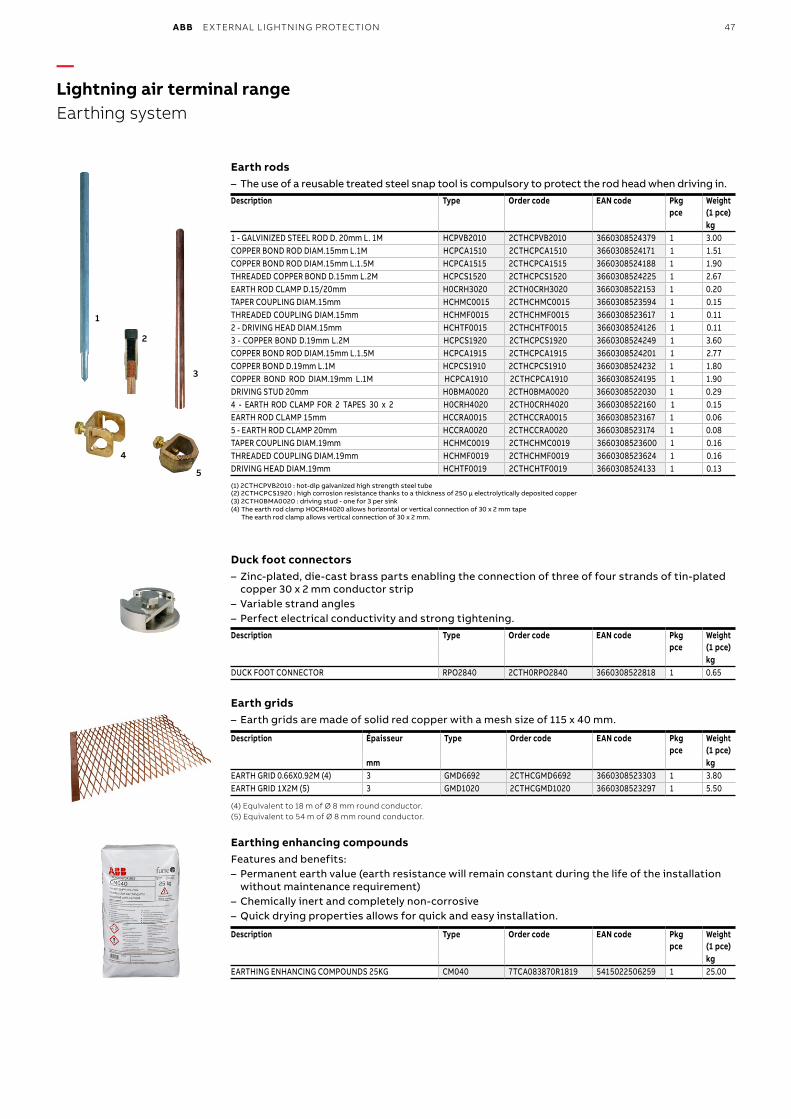
ABB EXTERNAL LIGHTNING PROTECTION 47
—Lightning air terminal rangeEarthing system
1
2
3
4
5
Earth rods – The use of a reusable treated steel snap tool is compulsory to protect the rod head when driving in.
Description Type Order code EAN code Pkg pce
Weight (1 pce)kg
1 - GALVINIZED STEEL ROD D. 20mm L. 1M HCPVB2010 2CTHCPVB2010 3660308524379 1 3.00 COPPER BOND ROD DIAM.15mm L.1M HCPCA1510 2CTHCPCA1510 3660308524171 1 1.51 COPPER BOND ROD DIAM.15mm L.1.5M HCPCA1515 2CTHCPCA1515 3660308524188 1 1.90 THREADED COPPER BOND D.15mm L.2M HCPCS1520 2CTHCPCS1520 3660308524225 1 2.67 EARTH ROD CLAMP D.15/20mm H0CRH3020 2CTH0CRH3020 3660308522153 1 0.20 TAPER COUPLING DIAM.15mm HCHMC0015 2CTHCHMC0015 3660308523594 1 0.15 THREADED COUPLING DIAM.15mm HCHMF0015 2CTHCHMF0015 3660308523617 1 0.11 2 - DRIVING HEAD DIAM.15mm HCHTF0015 2CTHCHTF0015 3660308524126 1 0.11 3 - COPPER BOND D.19mm L.2M HCPCS1920 2CTHCPCS1920 3660308524249 1 3.60 COPPER BOND ROD DIAM.15mm L.1.5M HCPCA1915 2CTHCPCA1915 3660308524201 1 2.77 COPPER BOND D.19mm L.1M HCPCS1910 2CTHCPCS1910 3660308524232 1 1.80 COPPER BOND ROD DIAM.19mm L.1M HCPCA1910 2CTHCPCA1910 3660308524195 1 1.90 DRIVING STUD 20mm H0BMA0020 2CTH0BMA0020 3660308522030 1 0.294 - EARTH ROD CLAMP FOR 2 TAPES 30 x 2 H0CRH4020 2CTH0CRH4020 3660308522160 1 0.15 EARTH ROD CLAMP 15mm HCCRA0015 2CTHCCRA0015 3660308523167 1 0.06 5 - EARTH ROD CLAMP 20mm HCCRA0020 2CTHCCRA0020 3660308523174 1 0.08 TAPER COUPLING DIAM.19mm HCHMC0019 2CTHCHMC0019 3660308523600 1 0.16 THREADED COUPLING DIAM.19mm HCHMF0019 2CTHCHMF0019 3660308523624 1 0.16 DRIVING HEAD DIAM.19mm HCHTF0019 2CTHCHTF0019 3660308524133 1 0.13
(1) 2CTHCPVB2010 : hot-dip galvanized high strength steel tube(2) 2CTHCPCS1920 : high corrosion resistance thanks to a thickness of 250 µ electrolytically deposited copper (3) 2CTH0BMA0020 : driving stud - one for 3 per sink(4) The earth rod clamp H0CRH4020 allows horizontal or vertical connection of 30 x 2 mm tape
The earth rod clamp allows vertical connection of 30 x 2 mm.
Duck foot connectors – Zinc-plated, die-cast brass parts enabling the connection of three of four strands of tin-plated copper 30 x 2 mm conductor strip
– Variable strand angles – Perfect electrical conductivity and strong tightening.
Description Type Order code EAN code Pkg pce
Weight(1 pce)kg
DUCK FOOT CONNECTOR RPO2840 2CTH0RPO2840 3660308522818 1 0.65
Earth grids – Earth grids are made of solid red copper with a mesh size of 115 x 40 mm.
Description Épaisseur Type Order code EAN code Pkg pce
Weight(1 pce)
mm kgEARTH GRID 0.66X0.92M (4) 3 GMD6692 2CTHCGMD6692 3660308523303 1 3.80EARTH GRID 1X2M (5) 3 GMD1020 2CTHCGMD1020 3660308523297 1 5.50
(4) Equivalent to 18 m of Ø 8 mm round conductor. (5) Equivalent to 54 m of Ø 8 mm round conductor.
Earthing enhancing compoundsFeatures and benefits:
– Permanent earth value (earth resistance will remain constant during the life of the installation without maintenance requirement)
– Chemically inert and completely non-corrosive – Quick drying properties allows for quick and easy installation.
Description Type Order code EAN code Pkg pce
Weight(1 pce)kg
EARTHING ENHANCING COMPOUNDS 25KG CM040 7TCA083870R1819 5415022506259 1 25.00
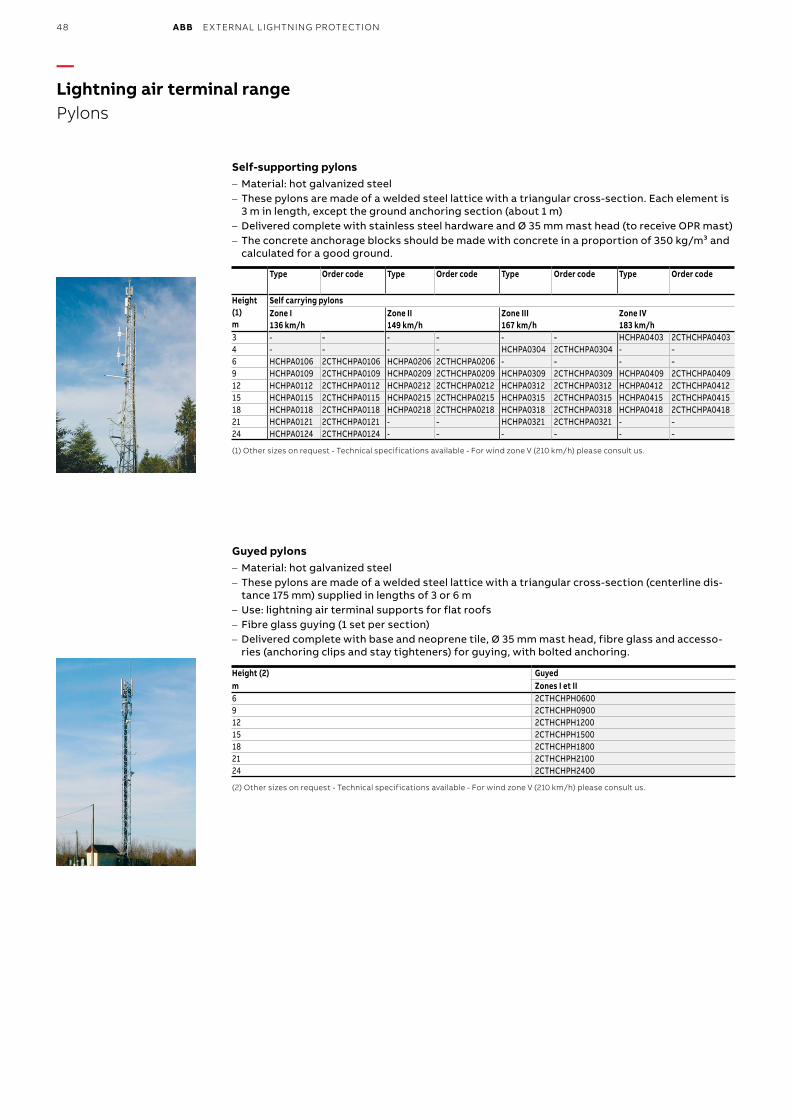
48 ABB EXTERNAL LIGHTNING PROTECTION
Self-supporting pylons– Material: hot galvanized steel– These pylons are made of a welded steel lattice with a triangular cross-section. Each element is
3 m in length, except the ground anchoring section (about 1 m)– Delivered complete with stainless steel hardware and Ø 35 mm mast head (to receive OPR mast)– The concrete anchorage blocks should be made with concrete in a proportion of 350 kg/m³ and
calculated for a good ground.
Type Order code Type Order code Type Order code Type Order code
Height(1)m
Self carrying pylonsZone I136 km/h
Zone II149 km/h
Zone III167 km/h
Zone IV183 km/h
3 - - - - - - HCHPA0403 2CTHCHPA04034 - - - - HCHPA0304 2CTHCHPA0304 - -6 HCHPA0106 2CTHCHPA0106 HCHPA0206 2CTHCHPA0206 - - - -9 HCHPA0109 2CTHCHPA0109 HCHPA0209 2CTHCHPA0209 HCHPA0309 2CTHCHPA0309 HCHPA0409 2CTHCHPA040912 HCHPA0112 2CTHCHPA0112 HCHPA0212 2CTHCHPA0212 HCHPA0312 2CTHCHPA0312 HCHPA0412 2CTHCHPA041215 HCHPA0115 2CTHCHPA0115 HCHPA0215 2CTHCHPA0215 HCHPA0315 2CTHCHPA0315 HCHPA0415 2CTHCHPA041518 HCHPA0118 2CTHCHPA0118 HCHPA0218 2CTHCHPA0218 HCHPA0318 2CTHCHPA0318 HCHPA0418 2CTHCHPA041821 HCHPA0121 2CTHCHPA0121 - - HCHPA0321 2CTHCHPA0321 - -24 HCHPA0124 2CTHCHPA0124 - - - - - -
(1) Other sizes on request - Technical specifications available - For wind zone V (210 km/h) please consult us.
Guyed pylons – Material: hot galvanized steel – These pylons are made of a welded steel lattice with a triangular cross-section (centerline dis-tance 175 mm) supplied in lengths of 3 or 6 m
– Use: lightning air terminal supports for flat roofs – Fibre glass guying (1 set per section) – Delivered complete with base and neoprene tile, Ø 35 mm mast head, fibre glass and accesso-ries (anchoring clips and stay tighteners) for guying, with bolted anchoring.
Height (2) Guyedm Zones I et II6 2CTHCHPH06009 2CTHCHPH090012 2CTHCHPH120015 2CTHCHPH150018 2CTHCHPH180021 2CTHCHPH2100 24 2CTHCHPH2400
(2) Other sizes on request - Technical specifications available - For wind zone V (210 km/h) please consult us.
—Lightning air terminal rangePylons
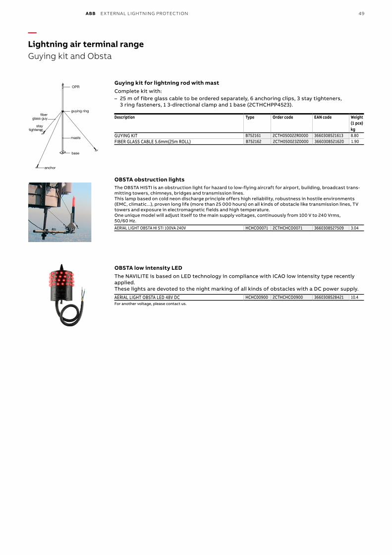
ABB EXTERNAL LIGHTNING PROTECTION 49
—Lightning air terminal rangeGuying kit and Obsta
OPR
guying ring
base
ber glass guy
stay tightener
anchor
masts
Guying kit for lightning rod with mastComplete kit with:– 25 m of fibre glass cable to be ordered separately, 6 anchoring clips, 3 stay tighteners,
3 ring fasteners, 1 3-directional clamp and 1 base (2CTHCHPP4523).
Description Type Order code EAN code Weight(1 pce)kg
GUYING KIT B752161 2CTH050022R0000 3660308521613 8.80FIBER GLASS CABLE 5.6mm(25m ROLL) B752162 2CTH050023Z0000 3660308521620 1.90
OBSTA obstruction lightsThe OBSTA HISTI is an obstruction light for hazard to low-flying aircraft for airport, building, broadcast trans-mitting towers, chimneys, bridges and transmission lines. This lamp based on cold neon discharge principle offers high reliability, robustness in hostile environments (EMC, climatic...), proven long life (more than 25 000 hours) on all kinds of obstacle like transmission lines, TV towers and exposure in electromagnetic fields and high temperature. One unique model will adjust itself to the main supply voltages, continuously from 100 V to 240 Vrms, 50/60 Hz.
AERIAL LIGHT OBSTA HI STI 100VA 240V HCHCO0071 2CTHCHCO0071 3660308527509 3.04
OBSTA low intensity LEDThe NAVILITE is based on LED technology in compliance with ICAO low intensity type recently applied. These lights are devoted to the night marking of all kinds of obstacles with a DC power supply.
AERIAL LIGHT OBSTA LED 48V DC HCHC00900 2CTHCHCO0900 3660308528421 10.4For another voltage, please contact us.
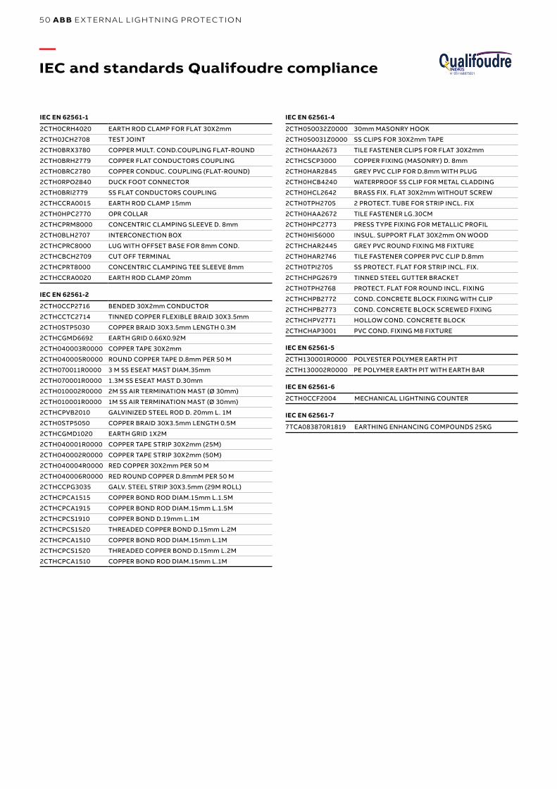
50 ABB EXTERNAL LIGHTNING PROTECTION
—IEC and standards Qualifoudre compliance N°051168875021
IEC EN 62561-1
2CTH0CRH4020 EARTH ROD CLAMP FOR FLAT 30X2mm
2CTH0JCH2708 TEST JOINT
2CTH0BRX3780 COPPER MULT. COND.COUPLING FLAT-ROUND
2CTH0BRH2779 COPPER FLAT CONDUCTORS COUPLING
2CTH0BRC2780 COPPER CONDUC. COUPLING (FLAT-ROUND)
2CTH0RPO2840 DUCK FOOT CONNECTOR
2CTH0BRI2779 SS FLAT CONDUCTORS COUPLING
2CTHCCRA0015 EARTH ROD CLAMP 15mm
2CTH0HPC2770 OPR COLLAR
2CTHCPRM8000 CONCENTRIC CLAMPING SLEEVE D. 8mm
2CTH0BLH2707 INTERCONECTION BOX
2CTHCPRC8000 LUG WITH OFFSET BASE FOR 8mm COND.
2CTHCBCH2709 CUT OFF TERMINAL
2CTHCPRT8000 CONCENTRIC CLAMPING TEE SLEEVE 8mm
2CTHCCRA0020 EARTH ROD CLAMP 20mm
IEC EN 62561-2
2CTH0CCP2716 BENDED 30X2mm CONDUCTOR
2CTHCCTC2714 TINNED COPPER FLEXIBLE BRAID 30X3.5mm
2CTH0STP5030 COPPER BRAID 30X3.5mm LENGTH 0.3M
2CTHCGMD6692 EARTH GRID 0.66X0.92M
2CTH040003R0000 COPPER TAPE 30X2mm
2CTH040005R0000 ROUND COPPER TAPE D.8mm PER 50 M
2CTH070011R0000 3 M SS ESEAT MAST DIAM.35mm
2CTH070001R0000 1.3M SS ESEAT MAST D.30mm
2CTH010002R0000 2M SS AIR TERMINATION MAST (Ø 30mm)
2CTH010001R0000 1M SS AIR TERMINATION MAST (Ø 30mm)
2CTHCPVB2010 GALVINIZED STEEL ROD D. 20mm L. 1M
2CTH0STP5050 COPPER BRAID 30X3.5mm LENGTH 0.5M
2CTHCGMD1020 EARTH GRID 1X2M
2CTH040001R0000 COPPER TAPE STRIP 30X2mm (25M)
2CTH040002R0000 COPPER TAPE STRIP 30X2mm (50M)
2CTH040004R0000 RED COPPER 30X2mm PER 50 M
2CTH040006R0000 RED ROUND COPPER D.8mmM PER 50 M
2CTHCCPG3035 GALV. STEEL STRIP 30X3.5mm (29M ROLL)
2CTHCPCA1515 COPPER BOND ROD DIAM.15mm L.1.5M
2CTHCPCA1915 COPPER BOND ROD DIAM.15mm L.1.5M
2CTHCPCS1910 COPPER BOND D.19mm L.1M
2CTHCPCS1520 THREADED COPPER BOND D.15mm L.2M
2CTHCPCA1510 COPPER BOND ROD DIAM.15mm L.1M
2CTHCPCS1520 THREADED COPPER BOND D.15mm L.2M
2CTHCPCA1510 COPPER BOND ROD DIAM.15mm L.1M
IEC EN 62561-4
2CTH050032Z0000 30mm MASONRY HOOK
2CTH050031Z0000 SS CLIPS FOR 30X2mm TAPE
2CTH0HAA2673 TILE FASTENER CLIPS FOR FLAT 30X2mm
2CTHCSCP3000 COPPER FIXING (MASONRY) D. 8mm
2CTH0HAR2845 GREY PVC CLIP FOR D.8mm WITH PLUG
2CTH0HCB4240 WATERPROOF SS CLIP FOR METAL CLADDING
2CTH0HCL2642 BRASS FIX. FLAT 30X2mm WITHOUT SCREW
2CTH0TPH2705 2 PROTECT. TUBE FOR STRIP INCL. FIX
2CTH0HAA2672 TILE FASTENER LG.30CM
2CTH0HPC2773 PRESS TYPE FIXING FOR METALLIC PROFIL
2CTH0HIS6000 INSUL. SUPPORT FLAT 30X2mm ON WOOD
2CTHCHAR2445 GREY PVC ROUND FIXING M8 FIXTURE
2CTH0HAR2746 TILE FASTENER COPPER PVC CLIP D.8mm
2CTH0TPI2705 SS PROTECT. FLAT FOR STRIP INCL. FIX.
2CTHCHPG2679 TINNED STEEL GUTTER BRACKET
2CTH0TPH2768 PROTECT. FLAT FOR ROUND INCL. FIXING
2CTHCHPB2772 COND. CONCRETE BLOCK FIXING WITH CLIP
2CTHCHPB2773 COND. CONCRETE BLOCK SCREWED FIXING
2CTHCHPV2771 HOLLOW COND. CONCRETE BLOCK
2CTHCHAP3001 PVC COND. FIXING M8 FIXTURE
IEC EN 62561-5
2CTH130001R0000 POLYESTER POLYMER EARTH PIT
2CTH130002R0000 PE POLYMER EARTH PIT WITH EARTH BAR
IEC EN 62561-6
2CTH0CCF2004 MECHANICAL LIGHTNING COUNTER
IEC EN 62561-7
7TCA083870R1819 EARTHING ENHANCING COMPOUNDS 25KG
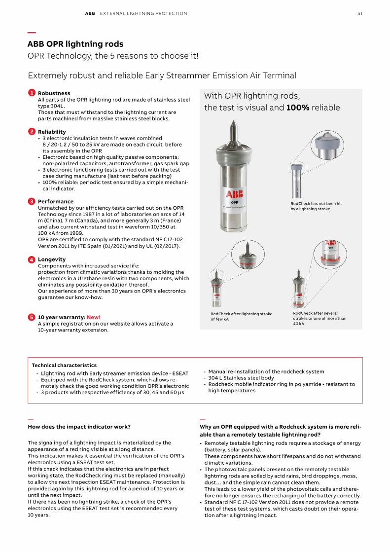
ABB EXTERNAL LIGHTNING PROTECTION 51
—ABB OPR lightning rodsOPR Technology, the 5 reasons to choose it!
Extremely robust and reliable Early Streammer Emission Air Terminal
RobustnessAll parts of the OPR lightning rod are made of stainless steel type 304L.Those that must withstand to the lightning current are parts machined from massive stainless steel blocks.
Reliability • 3 electronic insulation tests in waves combined
8 / 20-1.2 / 50 to 25 kV are made on each circuit before its assembly in the OPR
• Electronic based on high quality passive components: non-polarized capacitors, autotransformer, gas spark gap
• 3 electronic functioning tests carried out with the test case during manufacture (last test before packing)
• 100% reliable: periodic test ensured by a simple mechani-cal indicator.
PerformanceUnmatched by our efficiency tests carried out on the OPR Technology since 1987 in a lot of laboratories on arcs of 14 m (China), 7 m (Canada), and more generally 3 m (France) and also current withstand test in waveform 10/350 at 100 kA from 1999.OPR are certified to comply with the standard NF C17-102 Version 2011 by ITE Spain (01/2021) and by UL (02/2017).
Longevity Components with increased service life: protection from climatic variations thanks to molding the electronics in a Urethane resin with two components, which eliminates any possibility oxidation thereof.Our experience of more than 30 years on OPR's electronics guarantee our know-how.
10 year warranty: New! A simple registration on our website allows activate a 10-year warranty extension.
1
2
3
4
5
—How does the impact indicator work?
The signaling of a lightning impact is materialized by the appearance of a red ring visible at a long distance.This indication makes it essential the verification of the OPR's electronics using a ESEAT test set.If this check indicates that the electronics are in perfect working state, the RodCheck ring must be replaced (manually) to allow the next inspection ESEAT maintenance. Protection is provided again by this lightning rod for a period of 10 years or until the next impact.If there has been no lightning strike, a check of the OPR's electronics using the ESEAT test set is recommended every 10 years.
— Why an OPR equipped with a Rodcheck system is more reli-able than a remotely testable lightning rod?• Remotely testable lightning rods require a stockage of energy
(battery, solar panels). These components have short lifespans and do not withstand climatic variations.
• The photovoltaic panels present on the remotely testable lightning rods are soiled by acid rains, bird droppings, moss, dust… and the simple rain cannot clean them. This leads to a lower yield of the photovoltaic cells and there-fore no longer ensures the recharging of the battery correctly.
• Standard NF C 17-102 Version 2011 does not provide a remote test of these test systems, which casts doubt on their opera-tion after a lightning impact.
RodCheck has not been hit by a lightning stroke
RodCheck after lightning stroke of few kA
RodCheck after several strokes or one of more than 40 kA
With OPR lightning rods, the test is visual and 100% reliable
Technical characteristics - Lightning rod with Early streamer emission device - ESEAT - Equipped with the RodCheck system, which allows re-
motely check the good working condition OPR's electronic - 3 products with respective efficiency of 30, 45 and 60 µs
- Manual re-installation of the rodcheck system - 304 L Stainless steel body - Rodcheck mobile indicator ring in polyamide - resistant to
high temperatures
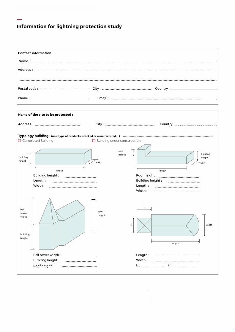
Magalie Gaber-Melek
Rectangle
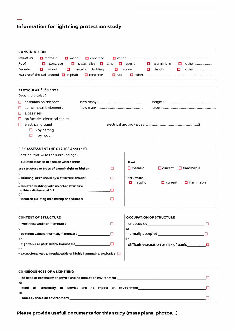
Magalie Gaber-Melek
Rectangle
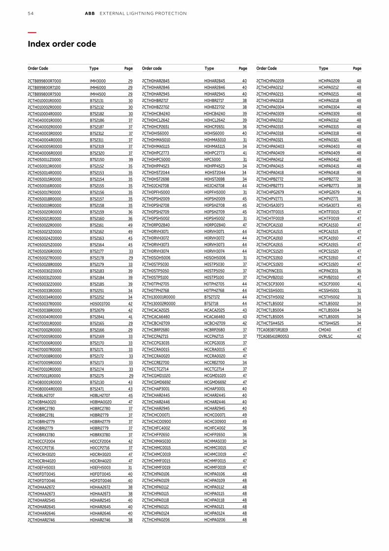
54 ABB EXTERNAL LIGHTNING PROTECTION
—Index order code
Order Code Type Page Order code Type Page Order Code Type Page
2CTB899800R7000 IMH3000 292CTB899800R7100 IMH6000 292CTB899800R7500 IMH4500 292CTH010001R0000 B752131 302CTH010002R0000 B752132 302CTH010004R0000 B752182 302CTH040001R0000 B752186 372CTH040002R0000 B752187 372CTH040003R0000 B752312 372CTH040004R0000 B752311 372CTH040005R0000 B752319 372CTH040006R0000 B752320 372CTH050011Z0000 B752150 392CTH050013R0000 B752152 352CTH050014R0000 B752153 352CTH050015R0000 B752154 352CTH050016R0000 B752155 352CTH050017R0000 B752156 352CTH050018R0000 B752157 352CTH050019R0000 B752158 352CTH050020R0000 B752159 362CTH050021R0000 B752160 362CTH050022R0000 B752161 492CTH050023Z0000 B752162 492CTH050024Z0000 B752163 452CTH050025Z0000 B752164 452CTH050026R0000 B752177 332CTH050027R0000 B752178 292CTH050028R0000 B752179 332CTH050030Z0000 B752183 392CTH050031Z0000 B752184 392CTH050032Z0000 B752185 392CTH050033R0000 B752251 342CTH050034R0000 B752252 342CTH050037R0000 H05003700 422CTH050038R0000 B752679 422CTH050040R0000 B752841 412CTH070001R0000 B752165 292CTH070002R0000 B752166 292CTH070005R0000 B752169 332CTH070006R0000 B752170 332CTH070007R0000 B752171 332CTH070008R0000 B752172 332CTH070009R0000 B752173 332CTH070010R0000 B752174 332CTH070011R0000 B752175 292CTH080001R0000 B752130 432CTH080004R0000 B752471 432CTH0BLH2707 H0BLH2707 452CTH0BMA0020 H0BMA0020 472CTH0BRC2780 H0BRC2780 372CTH0BRC2781 H0BRI2779 372CTH0BRH2779 H0BRH2779 372CTH0BRI2779 H0BRI2779 372CTH0BRX3780 H0BRX3780 372CTH0CCF2004 H0CCF2004 422CTH0CCP2716 H0CCP2716 372CTH0CRH3020 H0CRH3020 472CTH0CRH4020 H0CRH4020 472CTH0EFH5003 H0EFH5003 312CTH0FDT0045 H0FDT0045 402CTH0FDT0046 HOFDT0046 402CTH0HAA2672 H0HAA2672 382CTH0HAA2673 H0HAA2673 382CTH0HAR2545 H0HAR2545 402CTH0HAR2645 H0HAR2645 402CTH0HAR2646 H0HAR2646 402CTH0HAR2746 H0HAR2746 38
2CTH0HAR2845 H0HAR2845 402CTH0HAR2846 H0HAR2846 402CTH0HAR2945 H0HAR2945 402CTH0HBR2717 H0HBR2717 382CTH0HBZ2702 H0HBZ2702 382CTH0HCB4240 H0HCB4240 392CTH0HCL2642 H0HCL2642 392CTH0HCP2651 H0HCP2651 362CTH0HIS6000 H0HIS6000 402CTH0HMA5010 H0HMA5010 312CTH0HMA5115 H0HMA5115 342CTH0HPC2773 H0HPC2773 412CTH0HPC5000 HPC5000 312CTH0HPP4523 H0HPP4523 342CTH0HST2044 H0HST2044 342CTH0HST2698 H0HST2698 342CTH0JCH2708 H0JCH2708 442CTH0PFH5000 H0PFH5000 312CTH0PSH2009 H0PSH2009 452CTH0PSH2708 H0PSH2708 452CTH0PSH2709 H0PSH2709 452CTH0PSH5002 H0PSH5002 312CTH0RPO2840 H0RPO2840 472CTH0RVH3071 H0RVH3071 442CTH0RVH3072 H0RVH3072 442CTH0RVH3073 H0RVH3073 442CTH0RVH3074 H0RVH3074 442CTH0SOH5006 H0SOH5006 312CTH0STP5030 H0STP5030 372CTH0STP5050 H0STP5050 372CTH0STP5100 H0STP5100 372CTH0TPH2705 H0TPH2705 442CTH0TPH2768 H0TPH2768 442CTH130001R0000 B7527172 442CTH130002R0000 B752718 442CTHCACA2025 HCACA2025 432CTHCACA6460 HCACA6460 432CTHCBCH2709 HCBCH2709 422CTHCBRP2680 HCBRP2680 372CTHCCPA2715 HCCPA2715 372CTHCCPG3035 HCCPG3035 372CTHCCRA0015 HCCRA0015 472CTHCCRA0020 HCCRA0020 472CTHCCRE2700 HCCRE2700 342CTHCCTC2714 HCCTC2714 372CTHCGMD1020 HCGMD1020 472CTHCGMD6692 HCGMD6692 472CTHCHAP3001 HCHAP3001 402CTHCHAR2445 HCHAR2445 402CTHCHAR2446 HCHAR2446 402CTHCHAR2945 HCHAR2945 402CTHCHCO0071 HCHCO0071 492CTHCHCO0900 HCHC00900 492CTHCHFC4002 HCHFC4002 362CTHCHFP2650 HCHFP2650 362CTHCHMA5030 HCHMA5030 342CTHCHMC0015 HCHMC0015 472CTHCHMC0019 HCHMC0019 472CTHCHMF0015 HCHMF0015 472CTHCHMF0019 HCHMF0019 472CTHCHPA0106 HCHPA0106 482CTHCHPA0109 HCHPA0109 482CTHCHPA0112 HCHPA0112 482CTHCHPA0115 HCHPA0115 482CTHCHPA0118 HCHPA0118 482CTHCHPA0121 HCHPA0121 482CTHCHPA0124 HCHPA0124 482CTHCHPA0206 HCHPA0206 48
2CTHCHPA0209 HCHPA0209 482CTHCHPA0212 HCHPA0212 482CTHCHPA0215 HCHPA0215 482CTHCHPA0218 HCHPA0218 482CTHCHPA0304 HCHPA0304 482CTHCHPA0309 HCHPA0309 482CTHCHPA0312 HCHPA0312 482CTHCHPA0315 HCHPA0315 482CTHCHPA0318 HCHPA0318 482CTHCHPA0321 HCHPA0321 482CTHCHPA0403 HCHPA0403 482CTHCHPA0409 HCHPA0409 482CTHCHPA0412 HCHPA0412 482CTHCHPA0415 HCHPA0415 482CTHCHPA0418 HCHPA0418 482CTHCHPB2772 HCHPB2772 382CTHCHPB2773 HCHPB2773 382CTHCHPG2679 HCHPG2679 412CTHCHPV2771 HCHPV2771 382CTHCHSA3073 HCHSA3073 452CTHCHTF0015 HCHTF0015 472CTHCHTF0019 HCHTF0019 472CTHCPCA1510 HCPCA1510 472CTHCPCA1515 HCPCA1515 472CTHCPCA1910 HCPCA1910 472CTHCPCA1915 HCPCA1915 472CTHCPCS1520 HCPCS1520 472CTHCPCS1910 HCPCS1910 472CTHCPCS1920 HCPCS1920 472CTHCPINCE01 HCPINCE01 362CTHCPVB2010 HCPVB2010 472CTHCSCP3000 HCSCP3000 412CTHCSSH5001 HCSSH5001 312CTHCSTH5002 HCSTH5002 312CTHCTLB5002 HCTLB5002 342CTHCTLB5004 HCTLB5004 342CTHCTLB5005 HCTLB5005 342CTHCTSH4525 HCTSH4525 347TCA083870R1819 CM040 477TCA085410R0053 OVRLSC 42
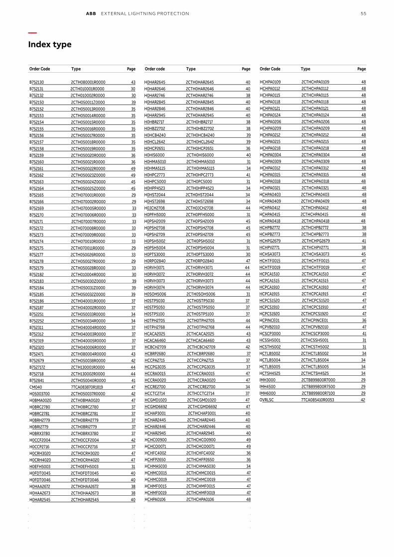
ABB EXTERNAL LIGHTNING PROTECTION 55
—Index type
Order Code Type Page Order code Type Page Order Code Type Page
B752130 2CTH080001R0000 43B752131 2CTH010001R0000 30B752132 2CTH010002R0000 30B752150 2CTH050011Z0000 39B752152 2CTH050013R0000 35B752153 2CTH050014R0000 35B752154 2CTH050015R0000 35B752155 2CTH050016R0000 35B752156 2CTH050017R0000 35B752157 2CTH050018R0000 35B752158 2CTH050019R0000 35B752159 2CTH050020R0000 36B752160 2CTH050021R0000 36B752161 2CTH050022R0000 49B752162 2CTH050023Z0000 49B752163 2CTH050024Z0000 45B752164 2CTH050025Z0000 45B752165 2CTH070001R0000 29B752166 2CTH070002R0000 29B752169 2CTH070005R0000 33B752170 2CTH070006R0000 33B752171 2CTH070007R0000 33B752172 2CTH070008R0000 33B752173 2CTH070009R0000 33B752174 2CTH070010R0000 33B752175 2CTH070011R0000 29B752177 2CTH050026R0000 33B752178 2CTH050027R0000 29B752179 2CTH050028R0000 33B752182 2CTH010004R0000 30B752183 2CTH050030Z0000 39B752184 2CTH050031Z0000 39B752185 2CTH050032Z0000 39B752186 2CTH040001R0000 37B752187 2CTH040002R0000 37B752251 2CTH050033R0000 34B752252 2CTH050034R0000 34B752311 2CTH040004R0000 37B752312 2CTH040003R0000 37B752319 2CTH040005R0000 37B752320 2CTH040006R0000 37B752471 2CTH080004R0000 43B752679 2CTH050038R0000 42B7527172 2CTH130001R0000 44 B752718 2CTH130002R0000 44B752841 2CTH050040R0000 41CM040 7TCA083870R1819 47H05003700 2CTH050037R0000 42 H0BMA0020 2CTH0BMA0020 47H0BRC2780 2CTH0BRC2780 37H0BRC2781 2CTH0BRC2781 37H0BRH2779 2CTH0BRH2779 37H0BRI2779 2CTH0BRI2779 37H0BRX3780 2CTH0BRX3780 37H0CCF2004 2CTH0CCF2004 42H0CCP2716 2CTH0CCP2716 37H0CRH3020 2CTH0CRH3020 47H0CRH4020 2CTH0CRH4020 47H0EFH5003 2CTH0EFH5003 31H0FDT0045 2CTH0FDT0045 40H0FDT0046 2CTH0FDT0046 40H0HAA2672 2CTH0HAA2672 38H0HAA2673 2CTH0HAA2673 38H0HAR2545 2CTH0HAR2545 40
H0HAR2645 2CTH0HAR2645 40H0HAR2646 2CTH0HAR2646 40H0HAR2746 2CTH0HAR2746 38H0HAR2845 2CTH0HAR2845 40H0HAR2846 2CTH0HAR2846 40H0HAR2945 2CTH0HAR2945 40H0HBR2717 2CTH0HBR2717 38H0HBZ2702 2CTH0HBZ2702 38H0HCB4240 2CTH0HCB4240 39H0HCL2642 2CTH0HCL2642 39H0HCP2651 2CTH0HCP2651 36H0HIS6000 2CTH0HIS6000 40H0HMA5010 2CTH0HMA5010 31H0HMA5115 2CTH0HMA5115 34H0HPC2773 2CTH0HPC2773 41H0HPC5000 2CTH0PC5000 31H0HPP4523 2CTH0HPP4523 34H0HST2044 2CTH0HST2044 34H0HST2698 2CTH0HST2698 34H0JCH2708 2CTH0JCH2708 44H0PFH5000 2CTH0PFH5000 31H0PSH2009 2CTH0PSH2009 45H0PSH2708 2CTH0PSH2708 45H0PSH2709 2CTH0PSH2709 45H0PSH5002 2CTH0PSH5002 31H0PSH5004 2CTH0PSH5004 31H0PTS3000 2CTH0PTS3000 30H0RPO2840 2CTH0RPO2840 47H0RVH3071 2CTH0RVH3071 44H0RVH3072 2CTH0RVH3072 44H0RVH3073 2CTH0RVH3073 44H0RVH3074 2CTH0RVH3074 44H0SOH5006 2CTH0SOH5006 31H0STP5030 2CTH0STP5030 37H0STP5050 2CTH0STP5050 37H0STP5100 2CTH0STP5100 37H0TPH2705 2CTH0TPH2705 44H0TPH2768 2CTH0TPH2768 44HCACA2025 2CTHCACA2025 43HCACA6460 2CTHCACA6460 43HCBCH2709 2CTHCBCH2709 42HCBRP2680 2CTHCBRP2680 37HCCPA2715 2CTHCCPA2715 37HCCPG3035 2CTHCCPG3035 37HCCRA0015 2CTHCCRA0015 47HCCRA0020 2CTHCCRA0020 47HCCRE2700 2CTHCCRE2700 34HCCTC2714 2CTHCCTC2714 37HCGMD1020 2CTHCGMD1020 47HCGMD6692 2CTHCGMD6692 47 HCHAP3001 2CTHCHAP3001 40HCHAR2445 2CTHCHAR2445 40HCHAR2446 2CTHCHAR2446 40HCHAR2945 2CTHCHAR2945 40HCHC00900 2CTHCHCO0900 49HCHCO0071 2CTHCHCO0071 49HCHFC4002 2CTHCHFC4002 36HCHFP2650 2CTHCHFP2650 36HCHMA5030 2CTHCHMA5030 34HCHMC0015 2CTHCHMC0015 47HCHMC0019 2CTHCHMC0019 47HCHMF0015 2CTHCHMF0015 47HCHMF0019 2CTHCHMF0019 47HCHPA0106 2CTHCHPA0106 48
HCHPA0109 2CTHCHPA0109 48HCHPA0112 2CTHCHPA0112 48HCHPA0115 2CTHCHPA0115 48HCHPA0118 2CTHCHPA0118 48HCHPA0121 2CTHCHPA0121 48HCHPA0124 2CTHCHPA0124 48HCHPA0206 2CTHCHPA0206 48HCHPA0209 2CTHCHPA0209 48HCHPA0212 2CTHCHPA0212 48HCHPA0215 2CTHCHPA0215 48HCHPA0218 2CTHCHPA0218 48HCHPA0304 2CTHCHPA0304 48HCHPA0309 2CTHCHPA0309 48HCHPA0312 2CTHCHPA0312 48HCHPA0315 2CTHCHPA0315 48HCHPA0318 2CTHCHPA0318 48HCHPA0321 2CTHCHPA0321 48HCHPA0403 2CTHCHPA0403 48HCHPA0409 2CTHCHPA0409 48HCHPA0412 2CTHCHPA0412 48HCHPA0415 2CTHCHPA0415 48HCHPA0418 2CTHCHPA0418 48HCHPB2772 2CTHCHPB2772 38HCHPB2773 2CTHCHPB2773 38HCHPG2679 2CTHCHPG2679 41HCHPV2771 2CTHCHPV2771 38HCHSA3073 2CTHCHSA3073 45HCHTF0015 2CTHCHTF0015 47HCHTF0019 2CTHCHTF0019 47HCPCA1510 2CTHCPCA1510 47HCPCA1515 2CTHCPCA1515 47HCPCA1910 2CTHCPCA1910 47HCPCA1915 2CTHCPCA1915 47HCPCS1520 2CTHCPCS1520 47HCPCS1910 2CTHCPCS1910 47HCPCS1920 2CTHCPCS1920 47HCPINCE01 2CTHCPINCE01 36HCPVB2010 2CTHCPVB2010 47HCSCP3000 2CTHCSCP3000 41HCSSH5001 2CTHCSSH5001 31HCSTH5002 2CTHCSTH5002 31HCTLB5002 2CTHCTLB5002 34HCTLB5004 2CTHCTLB5004 34HCTLB5005 2CTHCTLB5005 34HCTSH4525 2CTHCTSH4525 34IMH3000 2CTB899800R7000 29 IMH4500 2CTB899800R7500 29 IMH6000 2CTB899800R7100 29OVRLSC 7TCA085410R0053 42
www.abb.fr/lowvoltage
—ABB FranceBusiness Area ElectrificationHélita®1, avenue des Victimes du 11 juin 1944BP 303F-65203 Bagnères-de-Bigorre / France
Contact Commercial / Support techniqueTél. : +33 (0)1.34.40.23.22Email : [email protected]
1TX
H0
00
247C
020
6 -
Imp
rim
é en
Fra
nce
(04
.20
22 P
DF
)
Nous nous réservons le droit d'apporter des modifications techniques ou de modifier le contenu de ce documentsans préavis.ABB décline toute responsabilité concernant toute erreur potentielle ou tout manque d'information éventuel dansce document.
Nous nous réservons tous les droits relatifs à ce document, aux sujets et aux illustrations contenus dans ce document. Toute reproduction, divulgation à des tiers ou utilisation de son contenu, en tout ou en partie, sont interdites sans l'autorisation écrite préalable d'ABB.
Copyright© 2022 ABB - Tous droits réservés
Related Documents