// KNAPHEIDE VAN EQUIPMENT ASSEMBLY & INSTALLATION INSTRUCTIONS DOCUMENT # 68141-01 | JANUARY 2020 This document must not be copied or communicated to a third party without the expressed authorization of The Knapheide Manufacturing Company. FOR REF ONLY Printed copies are uncontrolled.

Welcome message from author
This document is posted to help you gain knowledge. Please leave a comment to let me know what you think about it! Share it to your friends and learn new things together.
Transcript
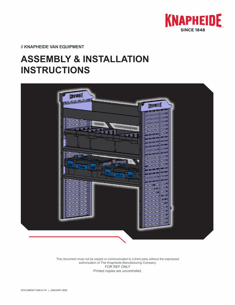
// KNAPHEIDE VAN EQUIPMENT
ASSEMBLY & INSTALLATION INSTRUCTIONS
DOCUMENT # 68141-01 | JANUARY 2020
This document must not be copied or communicated to a third party without the expressed authorization of The Knapheide Manufacturing Company.
FOR REF ONLYPrinted copies are uncontrolled.

2 // KNAPHEIDE | DOCUMENT # 68141-01 | JANUARY 2020
KNAPHEIDE VAN EQUIPMENT ASSEMBLY & INSTALLATION INSTRUCTIONS
INTRODUCTION
The following instructions detail the procedures for assembling & installing Knapheide Van Equipment.
The Knapheide Product Support Center1848 Westphalia Strasse | P.O. Box 7140 | Quincy, IL 62305
P: 217-592-5233 | [email protected]
Knapheide product warranty information can be found at
https://www.knapheide.com/files/source/knapheide/Service/Knapheide-Warranty.pdf
TABLE OF CONTENTS
Required Tools . . . . . . . . . . . . . . . . . . . . . . . . . . . . .3Mounting Parts . . . . . . . . . . . . . . . . . . . . . . . . . . . . .4Pre-Assembly Preparations . . . . . . . . . . . . . . . . . . . .6Shelving Unit Assembly . . . . . . . . . . . . . . . . . . . . . .10Shelving Unit Installation . . . . . . . . . . . . . . . . . . . . .16
This document must not be copied or communicated to a third party without the expressed authorization of The Knapheide Manufacturing Company.
FOR REF ONLYPrinted copies are uncontrolled.

KNAPHEIDE | DOCUMENT # 68141-01 | JANUARY 2020 // 3
// REQUIRED TOOLSTOOLS
Description Image
4 MM Allen Wrench4
Small Crescent Wrench
#2 Phillips Head Driver
Power Drill & 1/2” Drill Bit
Pop Rivet Gun
Bracket Bending Tool
4 // KNAPHEIDE | DOCUMENT # 68141-01 | JANUARY 2020
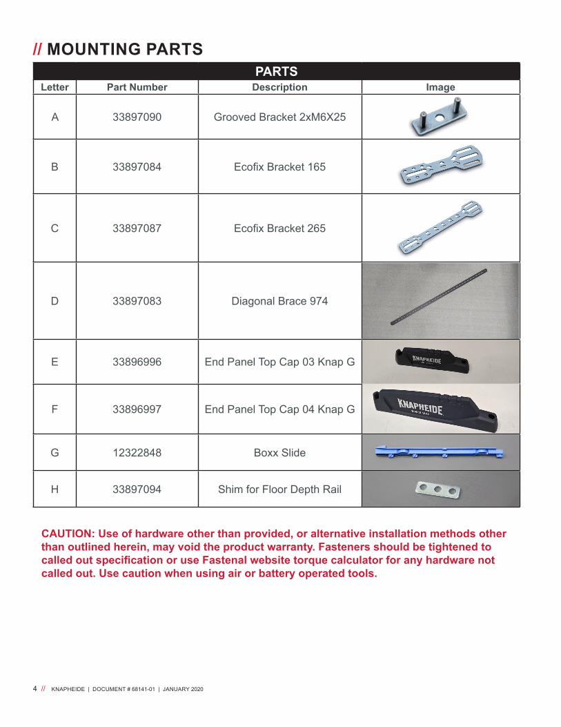
// MOUNTING PARTS
CAUTION: Use of hardware other than provided, or alternative installation methods other than outlined herein, may void the product warranty. Fasteners should be tightened to called out specification or use Fastenal website torque calculator for any hardware not called out. Use caution when using air or battery operated tools.
PARTSLetter Part Number Description Image
A 33897090 Grooved Bracket 2xM6X25
B 33897084 Ecofix Bracket 165
C 33897087 Ecofix Bracket 265
D 33897083 Diagonal Brace 974
E 33896996 End Panel Top Cap 03 Knap G
F 33896997 End Panel Top Cap 04 Knap G
G 12322848 Boxx Slide
H 33897094 Shim for Floor Depth Rail
KNAPHEIDE | DOCUMENT # 68141-01 | JANUARY 2020 // 5
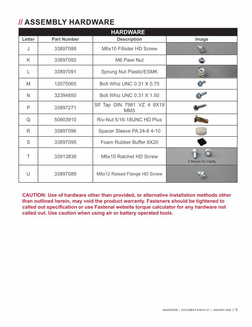
// ASSEMBLY HARDWARE
CAUTION: Use of hardware other than provided, or alternative installation methods other than outlined herein, may void the product warranty. Fasteners should be tightened to called out specification or use Fastenal website torque calculator for any hardware not called out. Use caution when using air or battery operated tools.
HARDWARELetter Part Number Description Image
J 33897088 M6x10 Fillister HD Screw
K 33897092 M6 Pawl Nut
L 33897091 Sprung Nut Plastic/ESMK
M 12075065 Bolt Whiz UNC 0.31 X 0.75
N 32394850 Bolt Whiz UNC 0.31 X 1.50
P 33897271 Slf Tap DIN 7981 VZ 4 8X19 MM3
Q 50903910 Riv-Nut 5/16-18UNC HD Plus
R 33897096 Spacer Sleeve PA 24-8 4-10
S 33897095 Foam Rubber Buffer 8X20
T 33913838 M6x10 Ratchet HD Screw
U 33897089 M6x12 Raised Flange HD Screw
2 Shown for Clarity

6 // KNAPHEIDE | DOCUMENT # 68141-01 | JANUARY 2020
// PRE-ASSEMBLY PREPARATIONSWARNING!Prior to drilling into any part of a vehicle, check behind and underneath drilling and mounting locations for electrical wire, fuel lines, brake lines, and other critical vehicle components. Adjust the drilling location as required to avoid these components. Failure to do so can result in death or serious injury in addition to impairing critical vehicle functions.
Measure from the vehicle cargo area floor to a horizontal brace on the vehicle sidewall... X
X
...to determine where the mounting brackets must be placed on the Knapheide Van Equip-ment shelf unit. Mark the end panels accord-ingly to indicate the proper location of the shelf.
“X” Shelf (Ref.)

KNAPHEIDE | DOCUMENT # 68141-01 | JANUARY 2020 // 7
// PRE-ASSEMBLY PREPARATIONS
Some vehicles may not be equipped with hori-zontal braces.
When horizontal braces are not available, the Knapheide Van Equipment shelf unit must be strategically placed in order to secure it to the vertical braces.
XX
X
X
Examples of Various Van Interiors With Horizontal Braces
Example of a Van Interior Without Horizontal Braces

8 // KNAPHEIDE | DOCUMENT # 68141-01 | JANUARY 2020
End Panel ModificationsEnd panels may be modified slightly to provide proper fitment and stability of the assembled shelving unit. In order to preserve the structural integrity of the shelving unit, DO NOT cut away more than 3.93 inches width (W) or more than 19.68 height (H) of end panel material.
Maximum Allowable LoadsEach shelf is rated for 177.8 lbs. maximum and each complete shelving unit is rated for 220 lbs. maximum. Shelving units should be designed so that heavier items are stored on the lowest shelves possible.
// PRE-ASSEMBLY PREPARATIONS

KNAPHEIDE | DOCUMENT # 68141-01 | JANUARY 2020 // 9
Laying Out Shelving ConfigurationsRefer to the graphics and tables below to determine desired shelf locations. 1 grid is equivalent to the dis-tance between the centerlines of two adjacent holes.
// PRE-ASSEMBLY PREPARATIONS
Grid L-Boxx LS-Boxx I-Boxx Rack
10 Grid = 10 holes
12 Grid = 12 holes
18 Grid = 18 holes
21 Grid = 21 holes
22 Grid = 22 holes
26 Grid = 26 holes
31 Grid = 31 holes
Grid S-Boxx M-Boxx T-Boxx8 Grid = 8 holes
12 Grid = 12 holes
10 // KNAPHEIDE | DOCUMENT # 68141-01 | JANUARY 2020
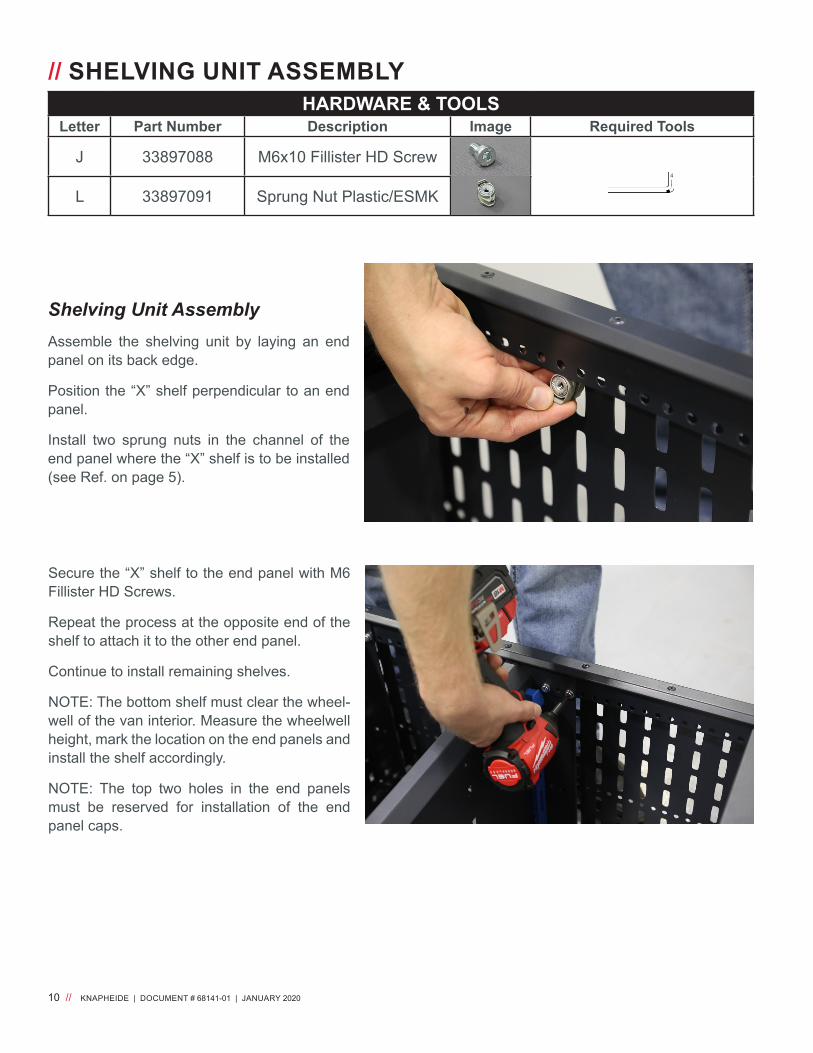
HARDWARE & TOOLSLetter Part Number Description Image Required Tools
J 33897088 M6x10 Fillister HD Screw
L 33897091 Sprung Nut Plastic/ESMK4
Secure the “X” shelf to the end panel with M6 Fillister HD Screws.
Repeat the process at the opposite end of the shelf to attach it to the other end panel.
Continue to install remaining shelves.
NOTE: The bottom shelf must clear the wheel-well of the van interior. Measure the wheelwell height, mark the location on the end panels and install the shelf accordingly.
NOTE: The top two holes in the end panels must be reserved for installation of the end panel caps.
Shelving Unit AssemblyAssemble the shelving unit by laying an end panel on its back edge.
Position the “X” shelf perpendicular to an end panel.
Install two sprung nuts in the channel of the end panel where the “X” shelf is to be installed (see Ref. on page 5).
// SHELVING UNIT ASSEMBLY

KNAPHEIDE | DOCUMENT # 68141-01 | JANUARY 2020 // 11
The diagonal brace attached to the shelf unit must always be attached at the front top of the unit.
// SHELVING UNIT ASSEMBLY

12 // KNAPHEIDE | DOCUMENT # 68141-01 | JANUARY 2020
// SHELVING UNIT ASSEMBLY
HARDWARE & TOOLSLetter Part Number Description Image Required Tools
D 33897083 Diagonal Brace
J 33897088 M6x10 Fillister HD Screw
K 33897092 M6 Pawl Nut
S 33897095 Foam Rubber Buffer 8X20
4
J V Y D K
J V Y D K V
Y D
S
Diagonal Brace Installation.

KNAPHEIDE | DOCUMENT # 68141-01 | JANUARY 2020 // 13
// SHELVING UNIT ASSEMBLY
HARDWARE & TOOLSLetter Part Number Description Image Required Tools
E & F 33896996 33896997
End Panel Top Cap 03 Knap G End Panel Top Cap 04 Knap G
P 33897271 Slf Tap DIN 7981 VZ 4 8X19 MM3
End Panel Top CapsUse a power drill and phillips head bit to install the End Panel Top Caps with Whiz Bolts.

14 // KNAPHEIDE | DOCUMENT # 68141-01 | JANUARY 2020
// SHELVING UNIT ASSEMBLY
HARDWARE & TOOLSLetter Part Number Description Image Required Tools
G 12322848 Boxx Slide
Box SlidesInsert Boxx Slide into holes on the shelf.
Push the Boxx Slide forward as far as it will go.
Press the Boxx Slide down until it snaps in place.
Underside of a shelf with Boxx Slides installed shown here.

KNAPHEIDE | DOCUMENT # 68141-01 | JANUARY 2020 // 15
HARDWARE & TOOLSLetter Part Number Description Image Required Tools
A 33897090 Grooved Bracket 2xM6X25
B 33897084 Ecofix Bracket 165
C 33897087 Ecofix Bracket 265
K 33897092 M6 Pawl Nut
// SHELVING UNIT ASSEMBLY
Bending Ecofix BracketsEcofix brackets can be bent with a bracket bending tool (P/N 32070270) or by hand.
Ecofix brackets can only be bent or twisted one time. DO NOT straighten a bent Ecofix bracket and bend it again as this will cause embrittle-ment!
DO NOT bend Ecofix brackets past 60º
If necessary, Ecofix brackets can be twisted to a maximum of 90º.
Examples of unacceptable bends to Ecofix brackets shown here. X X
ü
ü
ü

16 // KNAPHEIDE | DOCUMENT # 68141-01 | JANUARY 2020
// SHELVING UNIT INSTALLATION
45º45º
45º45º
45º45º
45º45º
Mounting Ecofix BracketsThe recommended position for mounting Eco-fix brackets is the horizontal position, as indi-cated by the dark bracket here.
Acceptable mounting positions, within 45º in either direction of the horizontal position, are indicated by the lighter brackets shown.
Unacceptable mounting positions, outside 45º in either direction of the horizontal position, are indicated by the lighter brackets shown.
Recommended and Acceptable Mounting Positions
Unacceptable Mounting Positions
ü
ü
X
X

KNAPHEIDE | DOCUMENT # 68141-01 | JANUARY 2020 // 17
EcoFix BracketsKnapheide Van Equip-
ment
Installation Kits
Directional Brackets
Thrust Brackets
4450-1 2 1 14460-1 2 2 14460-2 1 1 14660-1 2 3 14480-1 3 3 24480-2 1 1 14680-1 3 4 24680-2 1 1 1
// SHELVING UNIT INSTALLATION
Mounting Ecofix Brackets (cont.)Directional Motion vs. Thrust Motion.
Refer to the illustration below to better understand directional motion and thrust motion.
Knapheide Van Equipment units must be installed with Ecofix brackets properly mounted to counter the forces generated by both directional motion and thrust motion.
Ecofix bracket properly installed to counter thrust
motion.
Ecofix brackets properly installed to counter directional
motion.
DIRECTION of TRAVEL
The table at right lists how many installation kits are required for the various Knapheide Van Equipment units. It also shows how many brackets are incuded in each kit. These quanti-ties are derived from crash test data and must be closely adhered to.
Combining Ecofix brackets to counter the forces gen-erated by both motions is acceptable.

18 // KNAPHEIDE | DOCUMENT # 68141-01 | JANUARY 2020
// SHELVING UNIT INSTALLATION
HARDWARE & TOOLSLetter Part Number Description Image Required Tools
A 33897090 Grooved Bracket 2xM6X25
B 33897084 Ecofix Bracket 165
C 33897087 Ecofix Bracket 265
K 33897092 M6 Pawl Nut
Mounting Ecofix Brackets (cont.)Ecofix brackets must be mounted with grooved brackets (see above) and pawl nuts.
Attach the ecofix brackets to either the back of a shelf or the back edge of an end panel.

KNAPHEIDE | DOCUMENT # 68141-01 | JANUARY 2020 // 19
// SHELVING UNIT INSTALLATION
HARDWARE & TOOLSLetter Part Number Description Image Required Tools
M 12075065 Bolt WhizUNC 0.31 X 0.75
N 32394850 Bolt Whiz UNC 0.31 X 1.50
Q 50903910 Riv-Nut 5/16-18 UNC HD Plus
R 33897096 Spacer Sleeve PA 24-8 4-10
Shelving Unit Installation in VanStrategically place the Knapheide Van Equipment Shelv-ing Unit in the van where mounting brackets can be prop-erly attached to the inside of the van and the unit straddles the rear wheel well.
Mark all floor and wall mounting locations with a paint pen.
Remove the shelving unit from the van.
Use a power drill and a 1/2” drill bit to drill holes in each mounting hole location.
Install 5/16” plus-nuts in each hole.
Place the shelving unit back into the van and properly align the unit and brackets to the mounting holes.
Secure the unit to the van floor with whiz bolts. NOTE: If the van floor is ribbed, spacer sleeve(s) must be installed between the bottom of the unit and the van floor!
Secure the unit to the van wall with whiz bolts through each mounting bracket (use two whiz bolts per mounting location when possible).
WARNING!Prior to drilling into any part of a vehicle, check behind and underneath drilling and mounting locations for electrical wire, fuel lines, brake lines, and other critical vehicle components. Adjust the drilling location as required to avoid these components. Failure to do so can result in death or serious injury in addition to impairing critical vehicle functions.

20 // KNAPHEIDE | DOCUMENT # 68141-01 | JANUARY 2020
// SHELVING UNIT INSTALLATION
Van Specific InstallationsFord Transit Connect Vans (2014 & Newer)
When installing a Knapheide Van Equipment shelving unit in a 2014 or newer Ford Transit Connect van, space the unit 1½” to 2” off the wall to avoid drilling mounting holes through the floor and into the vehicle fuel tank.
Also make sure the bottom rear of the shelving unit is po-sitioned against the factory moulding across the rear of the vehicle.
Mark all floor and wall mounting locations with a paint pen.
Remove the shelving unit from the van.
Use a power drill and a 1/2” drill bit with a drill stop set to ¾” to drill holes in each mounting hole location.
Install 5/16” plus-nuts in each hole.
Place the shelving unit back into the van and properly align the unit and brackets to the mounting holes.
Secure the unit to the van floor with whiz bolts. NOTE: If the van floor is ribbed, spacer sleeve(s) must be installed between the bottom of the unit and the van floor!
Secure the unit to the van wall with 5-16” whiz bolts (.75 or 1.50 long) through each mounting bracket (use two whiz bolts per mounting location when possible).
1½” to 2”Gap
HARDWARE & TOOLSLetter Part Number Description Image Required Tools
H 33897094 Shim for Floor Depth Rail
M 12075065 Bolt WhizUNC 0.31 X 0.75
N 32394850 Bolt Whiz UNC 0.31 X 1.50
Q 50903910 Riv-Nut 5/16-18 UNC HD Plus
R 33897096 Spacer Sleeve PA 24-8 4-10

KNAPHEIDE | DOCUMENT # 68141-01 | JANUARY 2020 // 21
Ram CV Vans
The factory duct work at the rear curb inside must be trimmed to accomodate Knapheide Van Equipment Shelv-ing Unit installation.
Trim the duct work flush with the factory headliner.
// SHELVING UNIT INSTALLATION

22 // KNAPHEIDE | DOCUMENT # 68141-01 | JANUARY 2020
// SHELVING UNIT INSTALLATION
Completed Installation

DOCUMENT # 68141-01 | JANUARY 2020
The Knapheide Product Support Center1848 Westphalia Strasse | P.O. Box 7140 | Quincy, IL 62305
P: 217-592-5233 | [email protected]
© The Knapheide Manufacturing Company 2020
Related Documents