© JOHN PARKINSON 1

© JOHN PARKINSON 1 © JOHN PARKINSON 2 © JOHN PARKINSON 3 E L E C T R I C C U R R E N T Electrons Positive Ions Negative Ions Positive Holes.
Dec 27, 2015
Welcome message from author
This document is posted to help you gain knowledge. Please leave a comment to let me know what you think about it! Share it to your friends and learn new things together.
Transcript
©JOHN PARKINSON
1

©JOHN PARKINSON
2

©JOHN PARKINSON
3
E L E C T R I C C U R R E N T

©JOHN PARKINSON
4
+
Current (positive charge) flows from
POSITIVE to NEGATIVE
+++++++
Charge Q is measured in Coulombs [ symbol C ]
Current I is measured in Amps [ symbol A]
CURRENT = RATE OF FLOW OF CHARGE
+ve-ve

©JOHN PARKINSON
5
+ -I I
Conventional flow of Current in a Circuit

©JOHN PARKINSON
6
e-+ve-ve
Electrons flow from NEGATIVE to POSITIVE
Conventional Current - I

©JOHN PARKINSON
7
CURRENT =
THE CHARGE FLOWING
PER SECOND
t
QI
AMPS = COULOMBS per SECOND
tIQ
tIQ AMPS = COULOMBS per SECOND

©JOHN PARKINSON
8
1. A Conducting Path2. A Source of Potential Difference – p.d.
i.e. a source of VOLTS - V
A source of volts is referred to as an e.m.f.
…… an Electro Motive Force source
e.g. Cell [battery], Generator or Thermocouple
COLD COLD
cold hotV
©JOHN PARKINSON
9
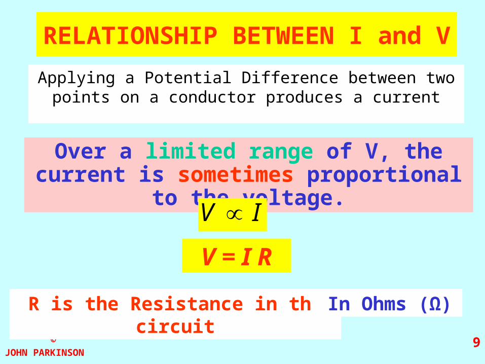
RELATIONSHIP BETWEEN I and V
Applying a Potential Difference between two points on a conductor produces a current
Over a limited range of V, the current is sometimes proportional to the voltage.
IV
V = I R
R is the Resistance in the circuit In Ohms (Ω)

©JOHN PARKINSON
10
Resistance can be thought of as a proportionality constant between I and V if Ohm’s Law applies.
It is also the opposition to the flow of current.
V = I R
OHM’s LAW
“The current through an ohmic conductor is directly proportional to the potential difference across it, provided there is no change in physical conditions
e.g. temperature.”
V
I R

©JOHN PARKINSON
11
Ohmic and non-ohmic conductors
V-V
-I
IOhmic eg resistor
or a piece of wire
Gradient RV
I 1

©JOHN PARKINSON
12
Ohmic and non-ohmic conductors
V-V
-I
INon-ohmic eg diode
forward bias
reverse bias
switch on pd for silicon = 0.6V

©JOHN PARKINSON
13
Ohmic and non-ohmic conductors
V-V
-I
INon-ohmic
eg filament bulb

©JOHN PARKINSON
14
RESISTORS
Colour codes are used to identify resistance value
Circuit symbol R
The ResistorColour Code
Colour Number
Black 0
Brown 1
Red 2
Orange 3
Yellow 4
Green 5
Blue 6
Violet 7
Grey 8
White 9
The four colour code bands are at one end of the component.
Counting from the end, the first three (or sometimes four or five)
bands give the resistance value and the last the tolerance
TOLERANCES
BROWN 1%
RED 2%
GOLD 5%
SILVER 10%
NONE 20%

©JOHN PARKINSON
15
AA
B
A = ?
B = ?
47 OOO , 1% Tolerance
47 OOO , 1% Tolerance

©JOHN PARKINSON
16
Resistivity ()
depends on the type of material and temperature
Units of ohm m (m)
R
How does resistance depend upon length?
How does resistance depend upon cross sectional area?
R 1/A
A
lR
A
lR
AA
©JOHN PARKINSON
17
Temperature / 0C
Res
ista
nce
/
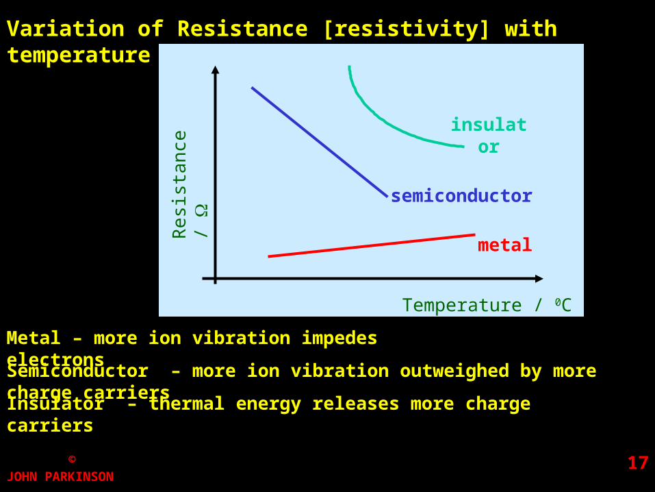
Variation of Resistance [resistivity] with temperature
semiconductor
insulator
metal
Metal – more ion vibration impedes electrons
Semiconductor – more ion vibration outweighed by more charge carriers
Insulator – thermal energy releases more charge carriers

©JOHN PARKINSON
18
PowerPower, Voltage and Current, Voltage and Current
The CurrentCurrent indicates how many CoulombsCoulombs flow each Second
The VoltageVoltage indicates how much energy each coulomb carries
The energy carried per second is the POWER
The power (in joules per second) = coulombs per second x joules per coulomb
Current (I) Voltage (V)
A joule per second is called a watt ( W )
The EnergyEnergy carried is measured in JoulesJoules
So work done W = Q V ( = I t V ) JoulesJoules
P = I VP = I V

©JOHN PARKINSON
19
PLUGS AND FUSES
3 A 13 A
LightSound
HeatMotion
5 A
up to 720W 720-3000W
liveneutralearth
230
P
V
PI
Related Documents