Meggitt SA, Route de Moncor 4, Case postale, 1701 Fribourg, Switzerland Tel: +41 26 407 11 11 Fax: +41 26 407 13 01 [email protected] www.meggittsensing.com/energy www.meggitt.com Information contained in this document may be subject to export control regulations of the European Union, USA or other countries. Each recipient of this document is responsible for ensuring that transfer or use of any information contained in this document complies with all relevant export control regulations. ECN N/A. DATA SHEET VM600 Mk2 MPC4 Mk2 + IOC4 Mk2 machinery protection and condition monitoring module IOC4 Mk2 MPC4 Mk2 KEY FEATURES AND BENEFITS • VibroSight ® compatible hardware from the vibro-meter ® product line • VM600 Mk2 (second generation) machinery protection and condition monitoring module • 4 dynamic channels and 2 auxiliary channels configurable as either tachometer inputs or DC inputs • VM600 Mk2 system safety-line to drive all system relays to a safe state • Diagnostics (built-in self-test (BIST)) provides continuous feedback on the health of the module • Individually configurable inputs (with sensor power supply outputs), channel filters, processing and outputs – with simultaneous data acquisition (fixed frequency or order tracked) • Up to 10 processed outputs per channel • Multiple alarms per processed output with configurable limits, hysteresis and time delay • AND, OR and majority voting logic functions for the combination of alarm and status information KEY BENEFITS AND FEATURES (continued) • Discrete outputs: 4 user-configurable relays for use by alarms and 1 common circuit-fault relay • Analog outputs: 4 outputs configurable as either 4 to 20 mA or 0 to 10 V • Conforms to API 670 • Direct system Ethernet communications • Compatible with VM600 Mk2 system racks (ABE04x) and slimline racks (ABE056)

Welcome message from author
This document is posted to help you gain knowledge. Please leave a comment to let me know what you think about it! Share it to your friends and learn new things together.
Transcript
Meggitt SA, Route de Moncor 4, Case postale, 1701 Fribourg, Switzerland Tel: +41 26 407 11 11Fax: +41 26 407 13 01
[email protected]/energy
www.meggitt.com
Information contained in this document may be subject to export control regulations of the European Union, USA or other countries. Each recipient of this document is responsible for ensuring that transfer or use of any information contained in this document complies with all relevant export control regulations. ECN N/A.
DATA SHEET
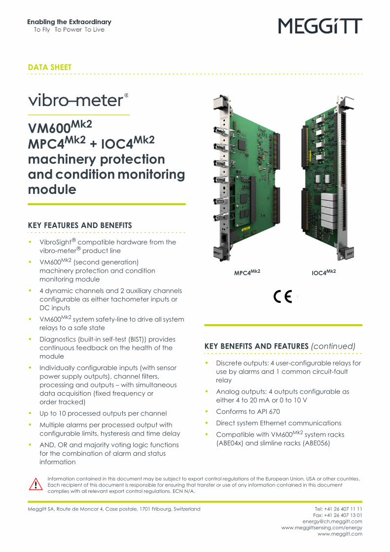
VM600Mk2
MPC4Mk2 + IOC4Mk2
machinery protection and condition monitoring module
IOC4Mk2MPC4Mk2
KEY FEATURES AND BENEFITS
• VibroSight ® compatible hardware from the vibro-meter ® product line
• VM600Mk2 (second generation) machinery protection and condition monitoring module
• 4 dynamic channels and 2 auxiliary channels configurable as either tachometer inputs or DC inputs
• VM600Mk2 system safety-line to drive all system relays to a safe state
• Diagnostics (built-in self-test (BIST)) provides continuous feedback on the health of the module
• Individually configurable inputs (with sensor power supply outputs), channel filters, processing and outputs – with simultaneous data acquisition (fixed frequency or order tracked)
• Up to 10 processed outputs per channel
• Multiple alarms per processed output with configurable limits, hysteresis and time delay
• AND, OR and majority voting logic functions for the combination of alarm and status information
KEY BENEFITS AND FEATURES (continued)
• Discrete outputs: 4 user-configurable relays for use by alarms and 1 common circuit-fault relay
• Analog outputs: 4 outputs configurable as either 4 to 20 mA or 0 to 10 V
• Conforms to API 670
• Direct system Ethernet communications
• Compatible with VM600Mk2 system racks (ABE04x) and slimline racks (ABE056)
DATA SHEETVM600Mk2 MPC4Mk2 + IOC4Mk2 machinery protection and condition monitoring module2 / 19
Document reference DS 268-121Version 8 – 29.11.2021
DESCRIPTION
IntroductionThe VM600Mk2 MPC4Mk2 + IOC4Mk2 machinery protection and condition monitoring module is designed for operation with the second generation of VM600Mk2 rack-based machinery protection system (MPS), from Meggitt’s vibro-meter ® product line. The VM600Mk2 MPC4Mk2 + IOC4Mk2 module consists of processing and input/output (interface) modules that provide 4 dynamic and 2 auxiliary channels of machinery protection and optional condition monitoring in VM600Mk2 systems.
VM600Mk2 rack-based monitoring systemsThe vibro-meter ® VM600Mk2 rack-based monitoring system is the evolution of Meggitt’s solution for the protection and monitoring of rotating machinery used in the power generation and oil & gas industries. VM600Mk2 solutions are recommended when a centralised monitoring system with a medium to large number of measurement points (channels) is required. It is typically used for the monitoring and/or protection of larger machinery such as gas, steam and hydro turbines, and generators, smaller machines such as compressors, fans, motors, pumps and propellers, as well as balance-of-plant (BOP) equipment.
A VM600Mk2 system consists of a 19" rack, a rack power supply and one or more monitoring modules. Optionally, relay modules and rack controller and communications interface modules can also be included.
Two types of rack are available: a VM600Mk2 system rack (ABE04x, 6U) that can house up to twelve monitoring modules, and a VM600Mk2 slimline rack (ABE056, 1U) that can house one monitoring module. The racks are typically
mounted in standard 19" rack cabinets or enclosures installed in an equipment room.
Different VM600Mk2 monitoring modules are available for machinery protection, condition monitoring and/or combustion monitoring applications. For example, the MPC4Mk2 + IOC4Mk2 module supports both machinery protection and condition monitoring, the XMV16 + XIO16T module supports extended condition monitoring for vibration and the XMC16 + XIO16T module supports extended condition monitoring for combustion.Note: For the MPC4Mk2 + IOC4Mk2 machinery protection and condition monitoring module, the machinery protection functionality is available by default, while the condition monitoring functionality is optional and depends on the purchased VibroSight ® software license.
The RLC16Mk2 relay module is an optional module used to provide additional relays when the four user-configurable relays per MPC4Mk2 + IOC4Mk2 module are not sufficient for an application.
The CPUMMk2 + IOCNMk2 rack controller and communications interface module is an optional module used to provide additional VM600Mk2 system functionality such as fieldbus communications; module data aggregation, processing and sharing; rack and/or fieldbus communications redundancy; front-panel alarm reset (AR); MPS rack (CPUx) security; system event and measurement event logging.VM600Mk2 rack-based monitoring systems complement the VibroSmart ® distributed monitoring systems that are also available from Meggitt’s vibro-meter ® product line, and are compatible with the same VibroSight ® machinery monitoring software suite.
KEY BENEFITS AND FEATURES (continued)
• Live insertion and removal of modules (hot-swappable) with automatic reconfiguration
• Software configurable
• Front-panel status indicators (LEDs)
APPLICATIONS
• VM600Mk2 MPC4Mk2 + IOC4Mk2 machinery protection
• VM600Mk2 MPC4Mk2 + IOC4Mk2 condition monitoring
• Vibration and/or combustion monitoring
• API 670 applications
Document reference DS 268-121Version 8 – 29.11.2021
DATA SHEETVM600Mk2 MPC4Mk2 + IOC4Mk2 machinery protection and condition monitoring module
3 / 19
DESCRIPTION (continued)
MPC4Mk2 + IOC4Mk2 module and VM600Mk2 racksA MPC4Mk2 + IOC4Mk2 machinery protection and condition monitoring module is used as part of a VM600Mk2 rack-based monitoring system. The MPC4Mk2 + IOC4Mk2 module can be used in a VM600Mk2 system rack (ABE04x) or slimline rack (ABE056).
The MPC4Mk2 module is always used with an associated IOC4Mk2 module as a pair/set of modules. Both the MPC4Mk2 and the IOC4Mk2 are single-width modules that occupy a single VM600Mk2 rack slot (module position). The MPC4Mk2 is installed in the front of a VM600Mk2 rack and the associated IOC4Mk2 is installed in the rear of the rack, in the slot directly behind the MPC4Mk2. Each module connects directly to the rack’s backplane using two connectors.
Note: The MPC4Mk2 + IOC4Mk2 module is compatible with all VM600Mk2 racks (ABE04x system racks and ABE056 slimline racks) and later VM600 racks.
System communicationsIn a VM600Mk2 system (one or more MPC4Mk2 + IOC4Mk2 modules and any associated RLC16Mk2 modules), the main communications interface is the LAN (Ethernet) connector on the front panel of each MPC4Mk2 module, which is used for used for communication with the VibroSight ® software running on an external computer.
In a VM600Mk2 rack (ABE4x), the VME bus can be used to share information between modules in the rack. For example, an MPC4Mk2 + IOC4Mk2 module can provide information such as measurement, alarm and/or status data to a CPUMMk2 + IOCNMk2 module which can then share the information via one of its industry standard fieldbuses.
In a VM600Mk2 system (one or more MPC4Mk2 + IOC4Mk2 modules and any associated MPC4Mk2 modules), the RLC16Mk2 modules are controlled and operated by a MPC4Mk2 , as determined by the configuration. The VM600Mk2 rack’s Open collector (OC) bus and Raw bus are used to exchange control and status information between the MPC4Mk2 + IOC4Mk2 and RLC16Mk2 modules.
RelaysThe MPC4Mk2 + IOC4Mk2 module includes five relays. The four user-configurable relays (RL1 to RL4) can be used by a VM600Mk2 system to remotely indicate system alarm and/or status information. While, a common circuit-fault relay (FAULT) is used to indicate a problem with the MPC4Mk2 + IOC4Mk2 module, as detected by the internal diagnostics (BIST).
The relays in a VM600Mk2 system (one or more MPC4Mk2 + IOC4Mk2 modules and any associated RLC16Mk2 modules), are driven by control circuitry that supports a VM600Mk2 system safety-line, that is, a system-wide control signal that automatically drives all system relays ( IOC4Mk2 and RLC16Mk2) and analog outputs ( IOC4Mk2) to a safe state should a problem be detected. In this way, IOC4Mk2 and RLC16Mk2 relays configured as normally energised (NE) can always be de-energised in the event of a problem with one of the components of the relay coil control signal.Note: This supports the “de-energise to trip principle” required in safety-related applications.
SoftwareMPC4Mk2 + IOC4Mk2 modules, as part of a VM600Mk2 system, are software configured using the VibroSight ® software.
To meet stringent cybersecurity and API 670 requirements, the MPC4Mk2 + IOC4Mk2 module segregates machinery protection (MPS) and condition monitoring (CMS) by using separate configurations and different VibroSight configuration software:• VibroSight Protect supports the configuration and operation of the machinery protection (MPS) functionality for a VM600Mk2 system.• VibroSight Capture supports the configuration and operation of the condition monitoring (CMS) functionality for a VM600Mk2 system.• Other VibroSight software modules support operations such as data display and analysis (VibroSight Vision), data logging and post-processing (VibroSight Server) system maintenance (VibroSight System Manager), etc.
DATA SHEETVM600Mk2 MPC4Mk2 + IOC4Mk2 machinery protection and condition monitoring module4 / 19
Document reference DS 268-121Version 8 – 29.11.2021
DESCRIPTION (continued)
More generally for extended condition monitoring system (CMS) applications, the VibroSight software supports the configuration and operation of XMx16 + XIO16T modules for condition monitoring and/or combustion monitoring, including the processing and presentation of measurement data for analysis. VibroSight is also used to configure and manage CPUMMk2 + IOCNMk2 modules.Note: The VibroSight ® software is also from the vibro-meter ® product line.
Applications informationAs part of a VM600Mk2 system, MPC4Mk2 + IOC4Mk2 machinery protection and condition monitoring modules are ideal for the protection and/or condition monitoring of critical assets such as gas, steam or hydro turbines and other high-value rotating machines in a wide range of industrial applications.
For further information, contact your local Meggitt representative.
Document reference DS 268-121Version 8 – 29.11.2021
DATA SHEETVM600Mk2 MPC4Mk2 + IOC4Mk2 machinery protection and condition monitoring module
5 / 19
SPECIFICATIONS
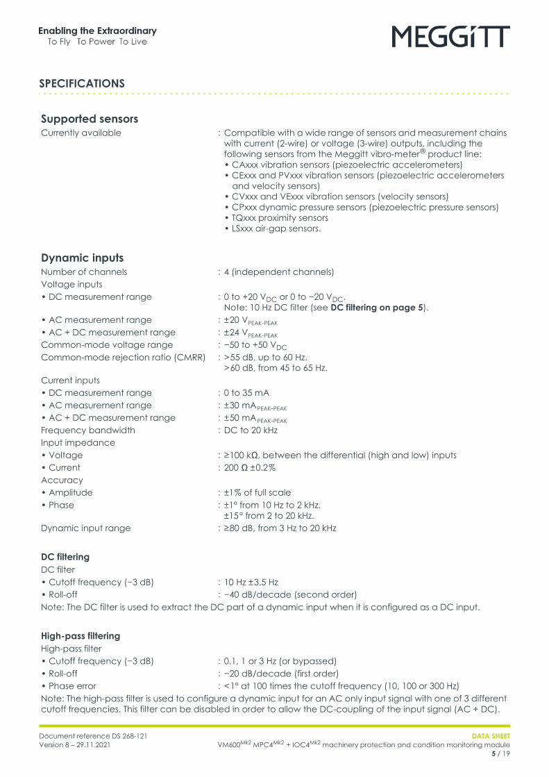
Supported sensorsCurrently available : Compatible with a wide range of sensors and measurement chains
with current (2-wire) or voltage (3-wire) outputs, including the following sensors from the Meggitt vibro-meter ® product line:• CAxxx vibration sensors (piezoelectric accelerometers) • CExxx and PVxxx vibration sensors (piezoelectric accelerometers and velocity sensors) • CVxxx and VExxx vibration sensors (velocity sensors)• CPxxx dynamic pressure sensors (piezoelectric pressure sensors) • TQxxx proximity sensors• LSxxx air-gap sensors.
Dynamic inputsNumber of channels : 4 (independent channels)Voltage inputs• DC measurement range : 0 to +20 VDC or 0 to −20 VDC.
Note: 10 Hz DC filter (see DC filtering on page 5).• AC measurement range : ± 20 VPEAK-PEAK • AC + DC measurement range : ± 24 VPEAK-PEAK Common-mode voltage range : −50 to +50 VDC Common-mode rejection ratio (CMRR) : > 55 dB, up to 60 Hz.
> 60 dB, from 45 to 65 Hz.Current inputs• DC measurement range : 0 to 35 mA• AC measurement range : ± 30 mA PEAK-PEAK
• AC + DC measurement range : ± 50 mA PEAK-PEAK
Frequency bandwidth : DC to 20 kHzInput impedance• Voltage : ≥ 100 kΩ, between the differential (high and low) inputs• Current : 200 Ω ± 0.2 %Accuracy• Amplitude : ±1 % of full scale• Phase : ±1° from 10 Hz to 2 kHz.
±15 ° from 2 to 20 kHz.Dynamic input range : ≥ 80 dB, from 3 Hz to 20 kHz
DC filteringDC filter• Cutoff frequency (−3 dB) : 10 Hz ± 3.5 Hz• Roll-off : −40 dB/decade (second order)Note: The DC filter is used to extract the DC part of a dynamic input when it is configured as a DC input.
High-pass filteringHigh-pass filter• Cutoff frequency (−3 dB) : 0.1, 1 or 3 Hz (or bypassed)• Roll-off : −20 dB/decade (first order)• Phase error : < 1° at 100 times the cutoff frequency (10, 100 or 300 Hz)Note: The high-pass filter is used to configure a dynamic input for an AC only input signal with one of 3 different cutoff frequencies. This filter can be disabled in order to allow the DC-coupling of the input signal (AC + DC).
DATA SHEETVM600Mk2 MPC4Mk2 + IOC4Mk2 machinery protection and condition monitoring module6 / 19
Document reference DS 268-121Version 8 – 29.11.2021
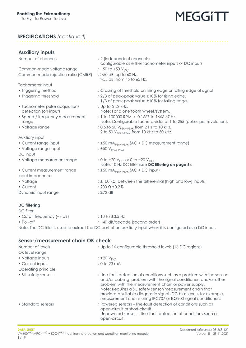
Auxiliary inputsNumber of channels : 2 (independent channels)
configurable as either tachometer inputs or DC inputsCommon-mode voltage range : −50 to +50 VDC Common-mode rejection ratio (CMRR) : > 50 dB, up to 60 Hz.
> 55 dB, from 45 to 65 Hz.Tachometer input• Triggering method : Crossing of threshold on rising edge or falling edge of signal• Triggering threshold : 2 /3 of peak-peak value ± 10 % for rising edge.
1 /3 of peak-peak value ± 10 % for falling edge.• Tachometer pulse acquisition/
detection (on input): Up to 51.2 kHz.
Note: For a one tooth wheel /system.• Speed / frequency measurement
range: 1 to 100 000 RPM / 0.1667 to 1666.67 Hz.
Note: Configurable tacho divider of 1 to 255 (pulses per revolution).• Voltage range : 0.6 to 50 VPEAK-PEAK from 2 Hz to 10 kHz.
2 to 50 VPEAK-PEAK from 10 kHz to 50 kHz.Auxiliary input• Current range input : ± 50 mA PEAK-PEAK (AC + DC measurement range)• Voltage range input : ± 50 VPEAK-PEAK DC input• Voltage measurement range : 0 to +20 VDC or 0 to −20 VDC.
Note: 10 Hz DC filter (see DC filtering on page 6).• Current measurement range : ± 50 mA PEAK-PEAK (AC + DC input)Input impedance• Voltage : ≥ 100 kΩ, between the differential (high and low) inputs• Current : 200 Ω ± 0.2 %Dynamic input range : ≥ 72 dB
DC filteringDC filter• Cutoff frequency (−3 dB) : 10 Hz ± 3.5 Hz• Roll-off : −40 dB/decade (second order)Note: The DC filter is used to extract the DC part of an auxiliary input when it is configured as a DC input.
Sensor / measurement chain OK checkNumber of levels : Up to 16 configurable threshold levels (16 DC regions)OK level range• Voltage inputs : ± 20 VDC • Current inputs : 0 to 23 mAOperating principle• SIL safety sensors : Line-fault detection of conditions such as a problem with the sensor
and/or cabling, problem with the signal conditioner, and/or other problem with the measurement chain or power supply.Note: Requires a SIL safety sensor/measurement chain that provides a suitable diagnostic signal (DC bias level), for example, measurement chains using IPC707 or IQS900 signal conditioners.
• Standard sensors : Powered sensors – line-fault detection of conditions such as open-circuit or short-circuit.Unpowered sensors – line-fault detection of conditions such as open-circuit.
SPECIFICATIONS (continued)
Document reference DS 268-121Version 8 – 29.11.2021
DATA SHEETVM600Mk2 MPC4Mk2 + IOC4Mk2 machinery protection and condition monitoring module
7 / 19
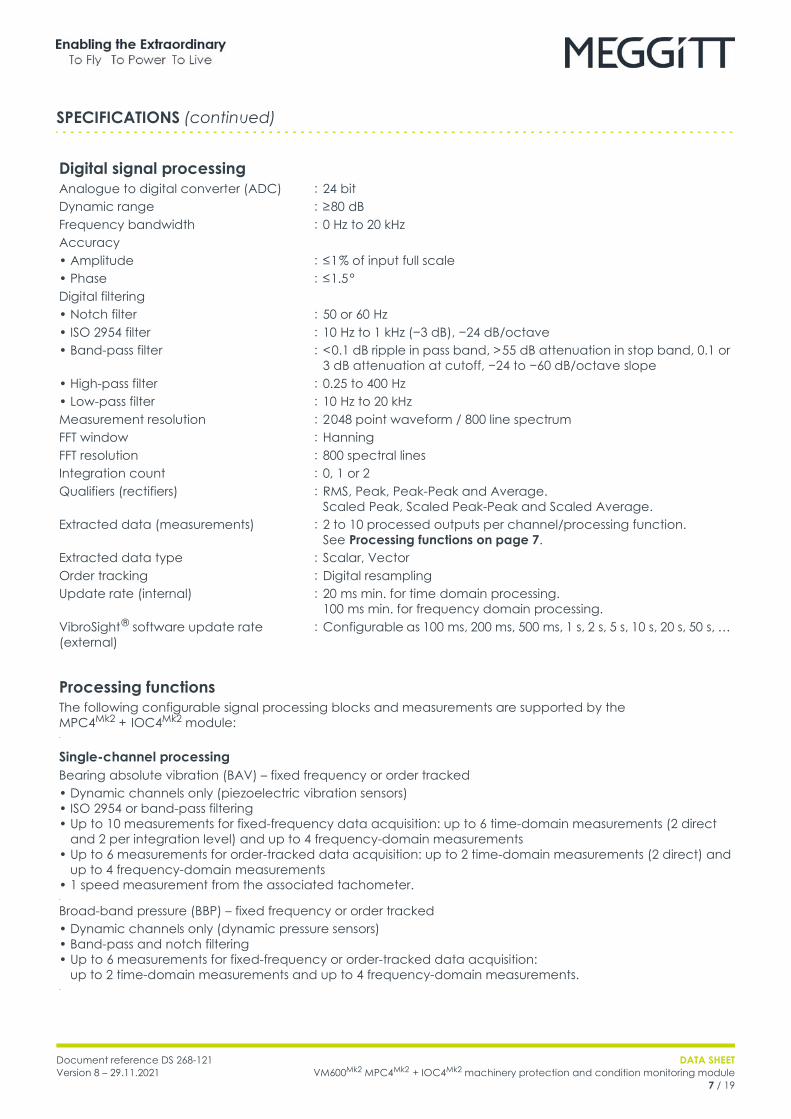
Digital signal processingAnalogue to digital converter (ADC) : 24 bitDynamic range : ≥ 80 dBFrequency bandwidth : 0 Hz to 20 kHzAccuracy• Amplitude : ≤ 1 % of input full scale• Phase : ≤ 1.5 °Digital filtering• Notch filter : 50 or 60 Hz• ISO 2954 filter : 10 Hz to 1 kHz (−3 dB), −24 dB/octave• Band-pass filter : < 0.1 dB ripple in pass band, > 55 dB attenuation in stop band, 0.1 or
3 dB attenuation at cutoff, −24 to −60 dB/octave slope• High-pass filter : 0.25 to 400 Hz• Low-pass filter : 10 Hz to 20 kHzMeasurement resolution : 2 048 point waveform / 800 line spectrumFFT window : HanningFFT resolution : 800 spectral linesIntegration count : 0, 1 or 2Qualifiers (rectifiers) : RMS, Peak, Peak-Peak and Average.
Scaled Peak, Scaled Peak-Peak and Scaled Average.Extracted data (measurements) : 2 to 10 processed outputs per channel/processing function.
See Processing functions on page 7.Extracted data type : Scalar, VectorOrder tracking : Digital resamplingUpdate rate (internal) : 20 ms min. for time domain processing.
100 ms min. for frequency domain processing.VibroSight ® software update rate (external)
: Configurable as 100 ms, 200 ms, 500 ms, 1 s, 2 s, 5 s, 10 s, 20 s, 50 s, …
Processing functionsThe following configurable signal processing blocks and measurements are supported by the MPC4Mk2 + IOC4Mk2 module:•
Single-channel processingBearing absolute vibration (BAV) – fixed frequency or order tracked• Dynamic channels only (piezoelectric vibration sensors)• ISO 2954 or band-pass filtering• Up to 10 measurements for fixed-frequency data acquisition: up to 6 time-domain measurements (2 direct
and 2 per integration level) and up to 4 frequency-domain measurements• Up to 6 measurements for order-tracked data acquisition: up to 2 time-domain measurements (2 direct) and
up to 4 frequency-domain measurements• 1 speed measurement from the associated tachometer.•
Broad-band pressure (BBP) – fixed frequency or order tracked• Dynamic channels only (dynamic pressure sensors)• Band-pass and notch filtering• Up to 6 measurements for fixed-frequency or order-tracked data acquisition:
up to 2 time-domain measurements and up to 4 frequency-domain measurements.•
SPECIFICATIONS (continued)
DATA SHEETVM600Mk2 MPC4Mk2 + IOC4Mk2 machinery protection and condition monitoring module8 / 19
Document reference DS 268-121Version 8 – 29.11.2021
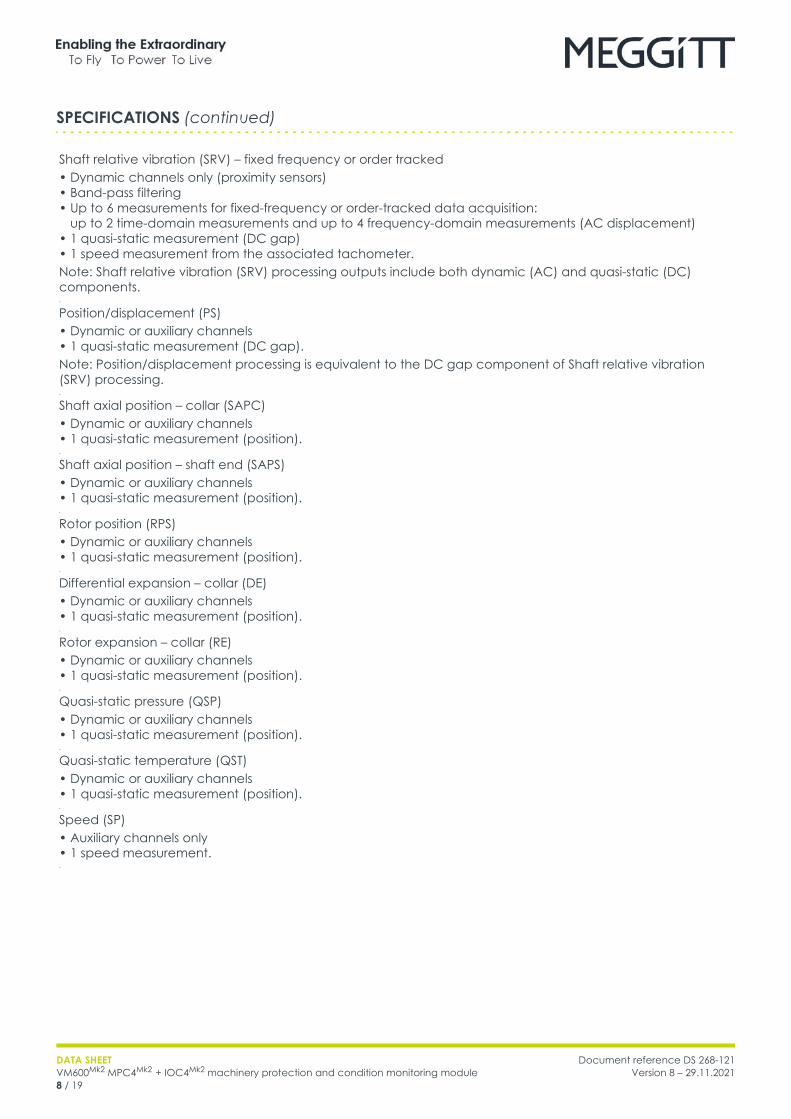
Shaft relative vibration (SRV) – fixed frequency or order tracked• Dynamic channels only (proximity sensors)• Band-pass filtering• Up to 6 measurements for fixed-frequency or order-tracked data acquisition:
up to 2 time-domain measurements and up to 4 frequency-domain measurements (AC displacement)• 1 quasi-static measurement (DC gap)• 1 speed measurement from the associated tachometer.Note: Shaft relative vibration (SRV) processing outputs include both dynamic (AC) and quasi-static (DC) components.•
Position/displacement (PS)• Dynamic or auxiliary channels• 1 quasi-static measurement (DC gap).Note: Position/displacement processing is equivalent to the DC gap component of Shaft relative vibration (SRV) processing.•
Shaft axial position – collar (SAPC)• Dynamic or auxiliary channels• 1 quasi-static measurement (position).•
Shaft axial position – shaft end (SAPS)• Dynamic or auxiliary channels• 1 quasi-static measurement (position).•
Rotor position (RPS)• Dynamic or auxiliary channels• 1 quasi-static measurement (position).•
Differential expansion – collar (DE)• Dynamic or auxiliary channels• 1 quasi-static measurement (position).•
Rotor expansion – collar (RE)• Dynamic or auxiliary channels• 1 quasi-static measurement (position).•
Quasi-static pressure (QSP)• Dynamic or auxiliary channels• 1 quasi-static measurement (position).•
Quasi-static temperature (QST)• Dynamic or auxiliary channels• 1 quasi-static measurement (position).•
Speed (SP)• Auxiliary channels only• 1 speed measurement.•
SPECIFICATIONS (continued)
Document reference DS 268-121Version 8 – 29.11.2021
DATA SHEETVM600Mk2 MPC4Mk2 + IOC4Mk2 machinery protection and condition monitoring module
9 / 19
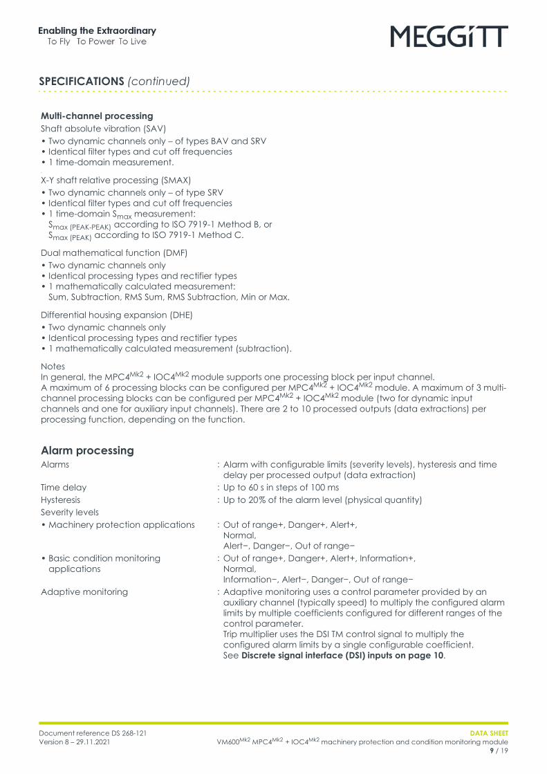
Multi-channel processingShaft absolute vibration (SAV)• Two dynamic channels only – of types BAV and SRV• Identical filter types and cut off frequencies• 1 time-domain measurement.•
X-Y shaft relative processing (SMAX)• Two dynamic channels only – of type SRV• Identical filter types and cut off frequencies• 1 time-domain Smax measurement:
Smax (PEAK-PEAK) according to ISO 7919-1 Method B, or Smax (PEAK) according to ISO 7919-1 Method C.
Dual mathematical function (DMF)• Two dynamic channels only• Identical processing types and rectifier types• 1 mathematically calculated measurement:
Sum, Subtraction, RMS Sum, RMS Subtraction, Min or Max.
Differential housing expansion (DHE)• Two dynamic channels only• Identical processing types and rectifier types• 1 mathematically calculated measurement (subtraction).
NotesIn general, the MPC4Mk2 + IOC4Mk2 module supports one processing block per input channel.A maximum of 6 processing blocks can be configured per MPC4Mk2 + IOC4Mk2 module. A maximum of 3 multi-channel processing blocks can be configured per MPC4Mk2 + IOC4Mk2 module (two for dynamic input channels and one for auxiliary input channels). There are 2 to 10 processed outputs (data extractions) per processing function, depending on the function.
Alarm processingAlarms : Alarm with configurable limits (severity levels), hysteresis and time
delay per processed output (data extraction)Time delay : Up to 60 s in steps of 100 msHysteresis : Up to 20 % of the alarm level (physical quantity)Severity levels• Machinery protection applications : Out of range+, Danger+, Alert+,
Normal,Alert−, Danger−, Out of range−
• Basic condition monitoring applications
: Out of range+, Danger+, Alert+, Information+,Normal,Information−, Alert−, Danger−, Out of range−
Adaptive monitoring : Adaptive monitoring uses a control parameter provided by an auxiliary channel (typically speed) to multiply the configured alarm limits by multiple coefficients configured for different ranges of the control parameter.Trip multiplier uses the DSI TM control signal to multiply the configured alarm limits by a single configurable coefficient. See Discrete signal interface (DSI) inputs on page 10.
SPECIFICATIONS (continued)
DATA SHEETVM600Mk2 MPC4Mk2 + IOC4Mk2 machinery protection and condition monitoring module10 / 19
Document reference DS 268-121Version 8 – 29.11.2021
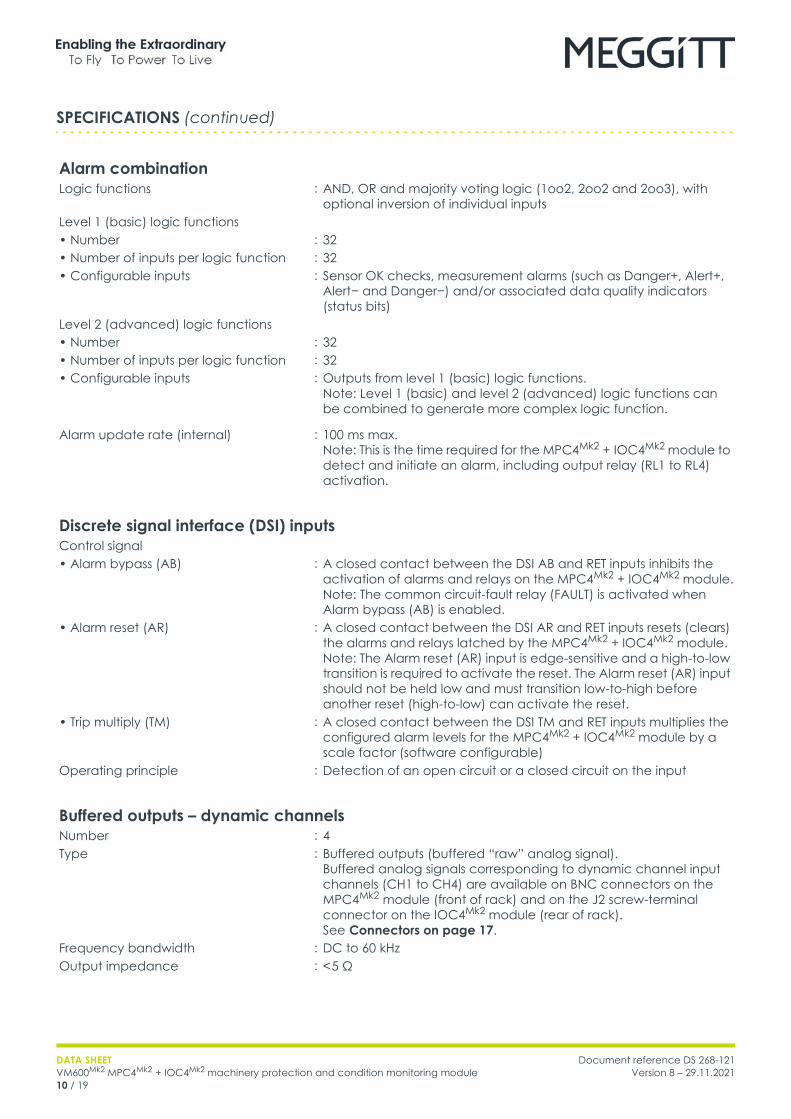
Alarm combinationLogic functions : AND, OR and majority voting logic (1oo2, 2oo2 and 2oo3), with
optional inversion of individual inputsLevel 1 (basic) logic functions• Number : 32• Number of inputs per logic function : 32• Configurable inputs : Sensor OK checks, measurement alarms (such as Danger+, Alert+,
Alert− and Danger−) and/or associated data quality indicators (status bits)
Level 2 (advanced) logic functions• Number : 32• Number of inputs per logic function : 32• Configurable inputs : Outputs from level 1 (basic) logic functions.
Note: Level 1 (basic) and level 2 (advanced) logic functions can be combined to generate more complex logic function.
Alarm update rate (internal) : 100 ms max.Note: This is the time required for the MPC4Mk2 + IOC4Mk2 module to detect and initiate an alarm, including output relay (RL1 to RL4) activation.
Discrete signal interface (DSI) inputsControl signal• Alarm bypass (AB) : A closed contact between the DSI AB and RET inputs inhibits the
activation of alarms and relays on the MPC4Mk2 + IOC4Mk2 module.Note: The common circuit-fault relay (FAULT) is activated when Alarm bypass (AB) is enabled.
• Alarm reset (AR) : A closed contact between the DSI AR and RET inputs resets (clears) the alarms and relays latched by the MPC4Mk2 + IOC4Mk2 module.Note: The Alarm reset (AR) input is edge-sensitive and a high-to-low transition is required to activate the reset. The Alarm reset (AR) input should not be held low and must transition low-to-high before another reset (high-to-low) can activate the reset.
• Trip multiply (TM) : A closed contact between the DSI TM and RET inputs multiplies the configured alarm levels for the MPC4Mk2 + IOC4Mk2 module by a scale factor (software configurable)
Operating principle : Detection of an open circuit or a closed circuit on the input
Buffered outputs – dynamic channelsNumber : 4Type : Buffered outputs (buffered “raw” analog signal).
Buffered analog signals corresponding to dynamic channel input channels (CH1 to CH4) are available on BNC connectors on the MPC4Mk2 module (front of rack) and on the J2 screw-terminal connector on the IOC4Mk2 module (rear of rack). See Connectors on page 17.
Frequency bandwidth : DC to 60 kHzOutput impedance : < 5 Ω
SPECIFICATIONS (continued)
Document reference DS 268-121Version 8 – 29.11.2021
DATA SHEETVM600Mk2 MPC4Mk2 + IOC4Mk2 machinery protection and condition monitoring module
11 / 19
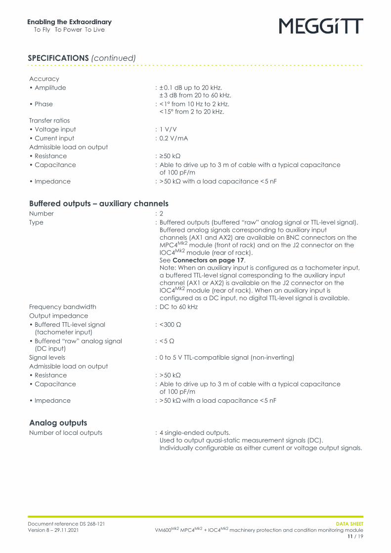
Accuracy• Amplitude : ± 0.1 dB up to 20 kHz.
± 3 dB from 20 to 60 kHz.• Phase : < 1° from 10 Hz to 2 kHz.
< 15° from 2 to 20 kHz.Transfer ratios• Voltage input : 1 V/ V• Current input : 0.2 V/ mAAdmissible load on output• Resistance : ≥ 50 kΩ• Capacitance : Able to drive up to 3 m of cable with a typical capacitance
of 100 pF/m• Impedance : > 50 kΩ with a load capacitance < 5 nF
Buffered outputs – auxiliary channelsNumber : 2Type : Buffered outputs (buffered “raw” analog signal or TTL-level signal).
Buffered analog signals corresponding to auxiliary input channels (AX1 and AX2) are available on BNC connectors on the MPC4Mk2 module (front of rack) and on the J2 connector on the IOC4Mk2 module (rear of rack).See Connectors on page 17. Note: When an auxiliary input is configured as a tachometer input, a buffered TTL-level signal corresponding to the auxiliary input channel (AX1 or AX2) is available on the J2 connector on the IOC4Mk2 module (rear of rack). When an auxiliary input is configured as a DC input, no digital TTL-level signal is available.
Frequency bandwidth : DC to 60 kHzOutput impedance• Buffered TTL-level signal
(tachometer input): < 300 Ω
• Buffered “raw” analog signal (DC input)
: < 5 Ω
Signal levels : 0 to 5 V TTL-compatible signal (non-inverting)Admissible load on output• Resistance : > 50 kΩ• Capacitance : Able to drive up to 3 m of cable with a typical capacitance
of 100 pF/m• Impedance : > 50 kΩ with a load capacitance < 5 nF
Analog outputsNumber of local outputs : 4 single-ended outputs.
Used to output quasi-static measurement signals (DC).Individually configurable as either current or voltage output signals.
SPECIFICATIONS (continued)
DATA SHEETVM600Mk2 MPC4Mk2 + IOC4Mk2 machinery protection and condition monitoring module12 / 19
Document reference DS 268-121Version 8 – 29.11.2021
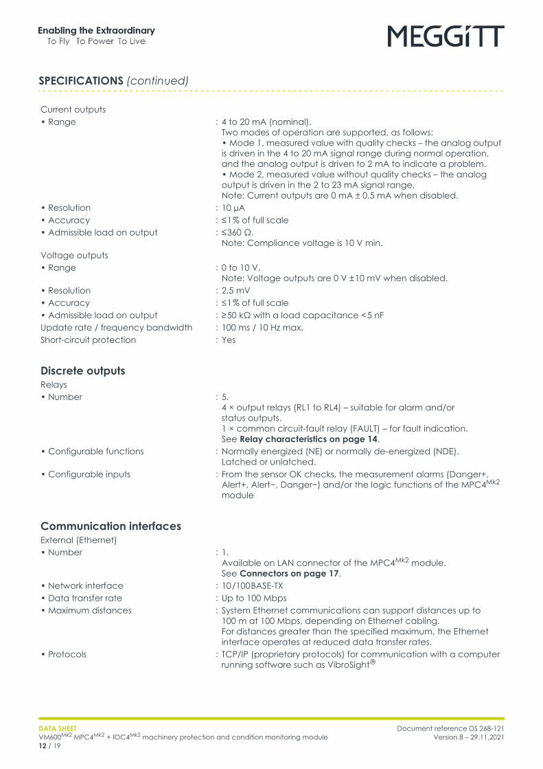
Current outputs• Range : 4 to 20 mA (nominal).
Two modes of operation are supported, as follows:• Mode 1, measured value with quality checks – the analog output is driven in the 4 to 20 mA signal range during normal operation, and the analog output is driven to 2 mA to indicate a problem.• Mode 2, measured value without quality checks – the analog output is driven in the 2 to 23 mA signal range.Note: Current outputs are 0 mA ± 0.5 mA when disabled.
• Resolution : 10 µA• Accuracy : ≤ 1 % of full scale• Admissible load on output : ≤ 360 Ω.
Note: Compliance voltage is 10 V min.Voltage outputs• Range : 0 to 10 V.
Note: Voltage outputs are 0 V ± 10 mV when disabled.• Resolution : 2.5 mV• Accuracy : ≤ 1 % of full scale• Admissible load on output : ≥ 50 kΩ with a load capacitance < 5 nFUpdate rate / frequency bandwidth : 100 ms / 10 Hz max.Short-circuit protection : Yes
Discrete outputsRelays• Number : 5.
4 × output relays (RL1 to RL4) – suitable for alarm and/or status outputs.1 × common circuit-fault relay (FAULT) – for fault indication.See Relay characteristics on page 14.
• Configurable functions : Normally energized (NE) or normally de-energized (NDE).Latched or unlatched.
• Configurable inputs : From the sensor OK checks, the measurement alarms (Danger+, Alert+, Alert−, Danger−) and/or the logic functions of the MPC4Mk2 module
Communication interfacesExternal (Ethernet)• Number : 1.
Available on LAN connector of the MPC4Mk2 module. See Connectors on page 17.
• Network interface : 10 /100 BASE-TX• Data transfer rate : Up to 100 Mbps• Maximum distances : System Ethernet communications can support distances up to
100 m at 100 Mbps, depending on Ethernet cabling.For distances greater than the specified maximum, the Ethernet interface operates at reduced data transfer rates.
• Protocols : TCP/IP (proprietary protocols) for communication with a computer running software such as VibroSight ®
SPECIFICATIONS (continued)
Document reference DS 268-121Version 8 – 29.11.2021
DATA SHEETVM600Mk2 MPC4Mk2 + IOC4Mk2 machinery protection and condition monitoring module
13 / 19
Internal (VME)• Bus interface : A24 / D16 slave mode
Note: In a VM600Mk2 rack (ABE4x), the VME bus can be used to share information between modules in the rack. For example, MPC4Mk2 + IOC4Mk2 modules can provide information such as measurement, alarm and status data to a CPUMMk2 + IOCNMk2 rack controller module which can then share the information via one of its industry standard fieldbuses. While in the opposite direction, a CPUMMk2 + IOCNMk2 rack controller module can issue alarm bypass (AB), alarm reset (AR) and trip multiply (TM) commands to MPC4Mk2 + IOC4Mk2 modules in the rack (when modules are Unlocked (maintenance operating mode)).
VM600Mk2 module compatibility : The MPC4Mk2 + IOC4Mk2 module is compatible with RLC16Mk2 modules as part of a VM600Mk2 system.The MPC4Mk2 + IOC4Mk2 module includes benefits and features such as improved measurement capability, VM600Mk2 system safety-line functionality and module diagnostics (BIST) that are not supported by the VM600Mk1 MPC4 / IOC4T card pair.Note: In a VM600Mk2 system, the MPC4Mk2 module automatically configures its relays as normally energized (NE) or normally de-energized (NDE), as per the configuration created using VibroSight Protect, whereas the VM600Mk1 RLC16 relay card uses jumpers on the card to manually configure the relays as NE or NDE.
System communicationsExternal : System communication interface (Ethernet) for communication
with VibroSight ® software running on an external computerInternal – VM600Mk2 VME : VME bus interface for communication with controlling/processing
modules via rack backplane. For example, with a CPUMMk2 + IOCNMk2 rack controller module.
Internal – VM600Mk2 rack buses : Open collector (OC) bus and/or Raw bus to share and monitor RLC16Mk2 module relays, and distribute the system-wide safety-line control signal.Raw bus to monitor/share the RLC16Mk2 module’s status.
Note: Generally, in a VM600Mk2 rack (ABE4x), the Raw bus is used to share dynamic input signals between processing modules, the Tacho bus is used to share tachometer (speed) input signals between processing modules, and the Open collector (OC) bus is used by processing modules to drive relay modules, all in the same rack. For example, the Raw bus and the Tacho bus are commonly used to share sensor signals (vibration and speed respectively) between different machinery protection modules and/or condition monitoring modules.Specifically for a VM600Mk2 system in a VM600Mk2 rack (ABE4x), the Open collector (OC) bus and/or Raw bus can be used to connect up to 32 outputs from a MPC4Mk2 + IOC4Mk2 machinery protection and condition monitoring module to RLC16Mk2 relay modules in the same rack, if additional relays are required.
External communication links /connections• Connection to a computer/network : The system communication interface (LAN connector on MPC4Mk2
module) can be used for connections/communications between the MPC4Mk2 module and a computer/network, using standard Ethernet cabling. See Connectors on page 17.
• VibroSight® software : Used for the configuration of a VM600Mk2 system (one or more MPC4Mk2 + IOC4Mk2 modules and any associated RLC16Mk2 modules)
SPECIFICATIONS (continued)
DATA SHEETVM600Mk2 MPC4Mk2 + IOC4Mk2 machinery protection and condition monitoring module14 / 19
Document reference DS 268-121Version 8 – 29.11.2021
ConfigurationMPC4Mk2 + IOC4Mk2 module : Software configurable via/over Ethernet, using a computer running
the VibroSight ® software.The IOC4Mk2 includes non-volatile memory that stores a copy of the configuration for the MPC4Mk2 + IOC4Mk2 module, such that if the MPC4Mk2 is replaced (hot-swapped), it is automatically reconfigured using the configuration from the IOC4Mk2 .Note: Jumpers on the IOC4Mk2 module are manually configured to select the VM600Mk2 rack’s Open collector (OC) bus and/or Raw bus lines that control and monitor the module’s relays, and distribute the system-wide VM600Mk2 system safety-line control signal. The jumper information is generated by the VibroSight ® software.
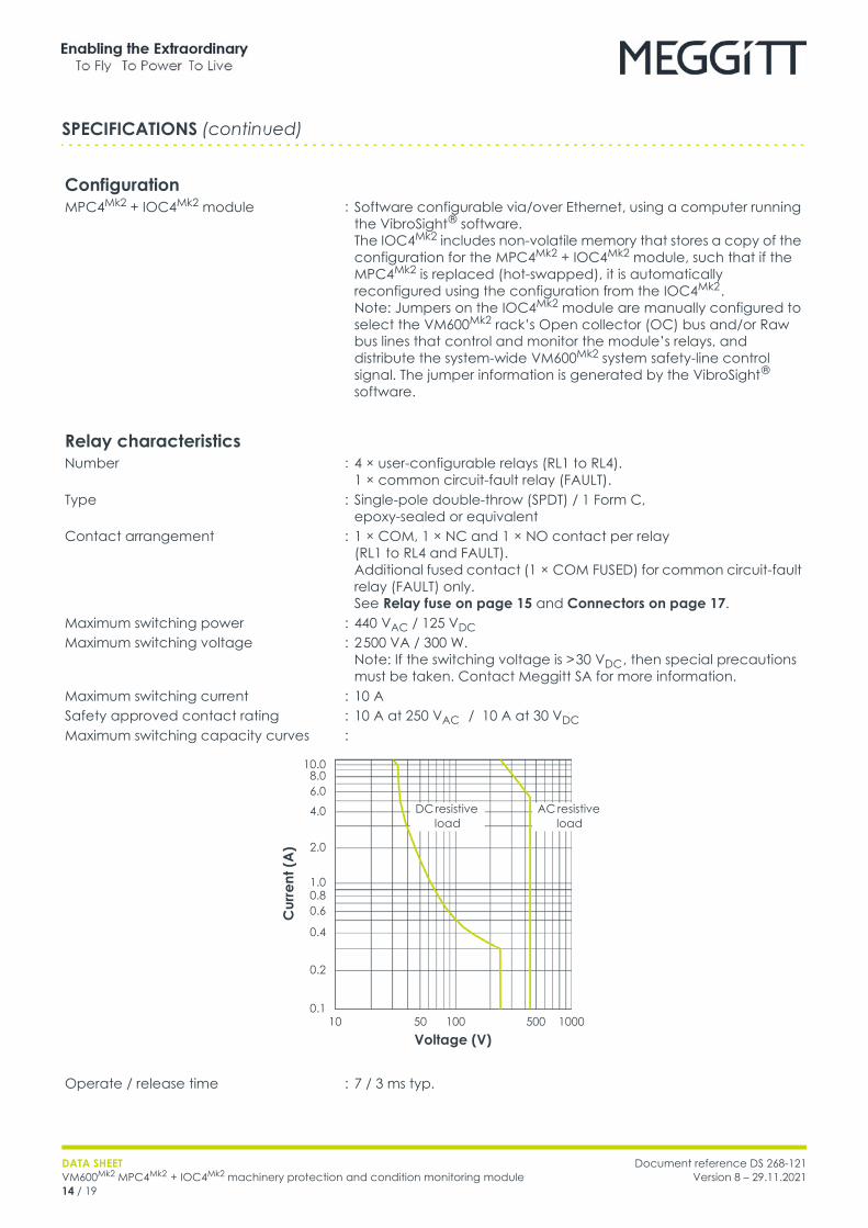
Relay characteristicsNumber : 4 × user-configurable relays (RL1 to RL4).
1 × common circuit-fault relay (FAULT).Type : Single-pole double-throw (SPDT) / 1 Form C,
epoxy-sealed or equivalentContact arrangement : 1 × COM, 1 × NC and 1 × NO contact per relay
(RL1 to RL4 and FAULT).Additional fused contact (1 × COM FUSED) for common circuit-fault relay (FAULT) only.See Relay fuse on page 15 and Connectors on page 17.
Maximum switching power : 440 VAC / 125 VDC Maximum switching voltage : 2 500 VA / 300 W.
Note: If the switching voltage is > 30 VDC , then special precautions must be taken. Contact Meggitt SA for more information.
Maximum switching current : 10 ASafety approved contact rating : 10 A at 250 VAC / 10 A at 30 VDC Maximum switching capacity curves :
Operate / release time : 7 / 3 ms typ.
SPECIFICATIONS (continued)
Voltage (V)
Cur
rent
(A)
1000
DC resistive load
10 50
10.0
1.0
0.1
0.80.6
0.4
0.2
2.0
4.0
6.08.0
100 500
AC resistive load
Document reference DS 268-121Version 8 – 29.11.2021
DATA SHEETVM600Mk2 MPC4Mk2 + IOC4Mk2 machinery protection and condition monitoring module
15 / 19
Dielectric strength• Between open contacts : 1000 VAC ( RMS ) • Between contact and coil : 5 000 VAC ( RMS ) Insulation resistance : 1000 MΩ min. (at 500 VDC , 50 % relative humidity (RH))Mechanical life : > 1 × 10⁷ operationsElectrical life : > 1 × 10⁵ operations (at 8 A, 250 VAC )
When used in a VM600Mk2 slimline rack (ABE056) with a DC power supply, the relay contacts on an IOC4Mk2 module have a maximum switching voltage of 70 VDC / 33 VAC (RMS) (46.7 VAC (PEAK)).
Relay fuseContact : Fused contact (COM FUSED) for common circuit-fault relay (FAULT)
only.See Relay characteristics on page 14 and Connectors on page 17.
Type : Littelfuse 443 series NANO2 ® surface-mount fuse (SMD) or equivalent
Characteristic : Time delay (T) / “Slo-Blo ® ”Current rating : 2 AVoltage rating : 250 VAC max.Interrupting rating (breaking capacity)
: 50 A (at 250 VAC )
Case style : Small rectangular surface-mount fuse (SMD) with square end blocks for insertion into a board-mounted (SMD) metal fuse clip/holder
EnvironmentalTemperature• Operating : −20 to 65 °C (−4 to 149 °F)• Storage : −40 to 85 °C (−40 to 185 °F)Humidity• Operating and storage : 0 to 95 % relative humidity (RH), non-condensingAltitude : 2 000 m (6 560 ft) max.
Note: Reduced air density affects cooling ability.
ApprovalsConformity : CE marking, European Union (EU) declaration of conformityElectromagnetic compatibility : EN 61000-6-2:2005.
EN 61000-6-4:2007 + A1:2011.Electrical safety : EN 61010-1:2010.
CAN/CSA-C22.2 No. 61010-1.Environmental management : RoHS compliant (2011/65/EU)Insulation coordination for measuring relays and protection equipment
: Separate circuits according to IEC 60255-27
Note: Some certifications and approvals for the VM600Mk2 MPC4Mk2 + IOC4Mk2 module are pending.
SPECIFICATIONS (continued)
DATA SHEETVM600Mk2 MPC4Mk2 + IOC4Mk2 machinery protection and condition monitoring module16 / 19
Document reference DS 268-121Version 8 – 29.11.2021
Power supply to module (input)Power source : VM600Mk2 rack power supplySupply voltages : +5 VDC and ± 12 VDC Consumption• MPC4Mk2 : < 6 W• IOC4Mk2 : < 9 WTotal power consumption (MPC4Mk2 + IOC4Mk2 module)
: < 15 W
Power supplies to sensors (output)Number : 6 × independent sensor power supplies.
Note: One per input/channel (CH1 to CH4, AX1 and AX2).Power supply output• Constant voltage : +24 or −24 VDC ± 3 % at up to 35 mA max.
Note: Short-circuit protected.• Constant current : +6 mA ±1 %.
Note: Voltage compliance > 22 VDC .
Control inputsMPC4Mk2
• Button 1 (left) : Used to run the proof test for the MPC4Mk2 + IOC4Mk2 module• Button 2 (right) : Used to lock/unlock the MPC4Mk2 + IOC4Mk2 module, that is, to
switch between the main operating modes of a VM600Mk2 system (MPC4Mk2 + IOC4Mk2 modules and any associated RLC16Mk2 modules), as follows:• Locked (secure operating mode) – the VM600Mk2 system performs its monitoring and protection functions while ensuring the security of the modules/system and it’s configuration. That is, the configuration cannot be changed and maintenance activities cannot be performed.• Unlocked (maintenance operating mode) – the VM600Mk2 system performs its monitoring and protection functions without ensuring the security of the modules/system and it’s configuration. That is, the configuration can be changed and maintenance activities can be performed.Note: Physical access to a VM600Mk2 system (specifically, the MPC4Mk2 module) is required in order to change the operating mode and therefore to be able to change the machinery protection (MPS) functionality for a VM600Mk2 system.
• Reset : Simultaneously pushing buttons 1 (left) and 2 (right) is used to reset the MPC4Mk2 + IOC4Mk2 module and any associated RLC16Mk2 modules (VM600Mk2 system), resulting in a reboot and power-on self-test (POST)
IOC4Mk2
• DSI signals : See Discrete signal interface (DSI) inputs on page 10
SPECIFICATIONS (continued)
Document reference DS 268-121Version 8 – 29.11.2021
DATA SHEETVM600Mk2 MPC4Mk2 + IOC4Mk2 machinery protection and condition monitoring module
17 / 19
Status indicators (LEDs)MPC4Mk2
• DIAG/STATUS : Multicolour LED used to indicate the status of the MPC4Mk2 + IOC4Mk2 module, such as normal operation, configuration status or internal hardware or firmware failures
• CH1 to CH4 : Multicolour LEDs used to indicate the status of the dynamic channels (CH1 to CH4)
• AX1 and AX2 : Multicolour LEDs used to indicate the status of the auxiliary channels (AX1 and AX2)
• LOCK : LED used to indicate the main operating mode of the MPC4Mk2 + IOC4Mk2 module (VM600Mk2 system): Locked (safety operating mode) or Unlocked (maintenance operating mode)
• LAN : LAN connector link and activity LEDs to indicate the status of the system LAN (Ethernet) communications
ConnectorsMPC4Mk2
• CH1 to CH4 : BNC connectors (female).Buffered “raw” sensor/measurement chain signals for the dynamic channel inputs (CH1 to CH4).Note: For the dynamic channels, the buffered “raw” outputs are analog signals.
• AX1 and AX2 : BNC connectors (female).Buffered “raw” sensor/measurement chain signals for the auxiliary channel inputs (AX1 and AX2).Note: For the auxiliary channels, the buffered “raw” outputs are analog signals. Corresponding digital signals are available on J2.
• LAN : 8P8C (RJ45) modular jack, female.System Ethernet for communication between the MPC4Mk2 + IOC4Mk2 module and a computer running the VibroSight ® software.
IOC4Mk2
• J1 : 24-pin S2L connector (male), compatible with 24-pin B2CF plug-in connectors (female) with PUSH IN spring connections and B2L plug-in connectors (female) with tension clamp spring connections.Inputs (analog signals) for the dynamic channels (CH1 to CH4) and the auxiliary channels (AX1 and AX2).
• J2 : 36-pin S2L connector (male), compatible with 36-pin B2CF plug-in connectors (female) with PUSH IN spring connections and B2L plug-in connectors (female) with tension clamp spring connections.Outputs (buffered “raw” signals) for the dynamic channels (CH1 to CH4) and the auxiliary channels (AX1 and AX2).Outputs (digital (pulse train) signals (TTL-level)) for the auxiliary channels (AX1 and AX2).Inputs and ground reference (digital signals) for the DSI control signals (AB, AR and TM).Outputs (analog signals) for the analog DC outputs.
SPECIFICATIONS (continued)
DATA SHEETVM600Mk2 MPC4Mk2 + IOC4Mk2 machinery protection and condition monitoring module18 / 19
Document reference DS 268-121Version 8 – 29.11.2021
• J3 : 16-pin connector (male), compatible with 16-pin MC/STF plug-in connectors (female) with screw-terminal connections.Outputs (contacts) for the common circuit-fault relay (FAULT) and the user-configurable relays (RL1 to RL4).
NotesThe connectors are removable to simplify installation and mounting.There is 1 × COM, 1 × NC and 1 × NO contact available per user-configurable relay (RL1 to RL4).There is 1 × COM, 1 × COM FUSED, 1 × NC and 1 × NO contact available per common circuit-fault relay (FAULT).
PhysicalMPC4Mk2
• Height : 6U (262 mm, 10.3 in)• Width : 20 mm (0.8 in)• Depth : 187 mm (7.4 in)• Weight : 0.42 kg (0.93 lb) approx.IOC4Mk2
• Height : 6U (262 mm, 10.3 in)• Width : 20 mm (0.8 in)• Depth : 125 mm (4.9 in)• Weight : 0.31 kg (0.68 lb) approx.
ORDERING INFORMATION
To order please specify
Type Designation Ordering number (PNR)MPC4Mk2 Different versions of the VM600Mk2 MPC4Mk2 + IOC4Mk2 processing
module:
– Standard version 600-041
IOC4Mk2 Different versions of the VM600Mk2 MPC4Mk2 + IOC4Mk2 input /output module:
– Standard version 600-043
NotesDifferent versions of the VM600Mk2 MPC4Mk2 + IOC4Mk2 machinery protection and condition monitoring module are available with an optional conformal coating (“varnish”) applied to the circuitry of the modules in order to provide additional environmental protection against chemicals, dust, moisture and temperature extremes.The VM600Mk2 MPC4Mk2 + IOC4Mk2 machinery protection and condition monitoring module supports both machinery protection and condition monitoring.The available functionality is determined by VibroSight ® software licensing, as follows: • Machinery protection functionality is always enabled. That is, MPC4Mk2 + IOC4Mk2 modules are restricted to machinery protection only by default VibroSight software licensing.• Condition monitoring functionality can be enabled, as required. That is, MPC4Mk2 + IOC4Mk2 modules can be configured to use condition monitoring by purchasing a VibroSight software license with an order option code that specifically enables the additional condition monitoring functionality.
SPECIFICATIONS (continued)
Meggitt (Meggitt PLC) is a leading international engineering company, headquartered in England, that designs and delivers high-performance components and subsystems for aerospace, defence and selected energy markets. Meggitt comprises four customer-aligned divisions: Airframe Systems, Engine Systems, Energy & Equipment and Services & Support.The Energy & Equipment division includes the Energy Sensing and Controls product group that specialises in sensing and monitoring solutions for a broad range of energy infrastructure, and control valves for industrial gas turbines, primarily for the Power Generation, Oil & Gas and Services markets. Energy & Equipment is headquartered in Switzerland (Meggitt SA) and incorporates the vibro-meter ® product line, which has over 65 years of sensor and systems expertise and is trusted by original equipment manufacturers (OEMs) globally.
All information in this document, such as descriptions, specifications, drawings, recommendations and other statements, is believed to be reliable and is stated in good faith as being approximately correct, but is not binding on Meggitt (Meggitt SA) unless expressly agreed in writing. Before acquiring and/or using this product, you must evaluate it and determine if it is suitable for your intended application. You should also check our website at www.meggittsensing.com/energy for any updates to data sheets, certificates, product drawings, user manuals, service bulletins and/or other instructions affecting the product.Unless otherwise expressly agreed in writing with Meggitt SA, you assume all risks and liability associated with use of the product. Any recommendations and advice given without charge, whilst given in good faith, are not binding on Meggitt SA. Meggitt (Meggitt SA) takes no responsibility for any statements related to the product which are not contained in a current Meggitt SA publication, nor for any statements contained in extracts, summaries, translations or any other documents not authored and produced by Meggitt SA.The certifications and warranties applicable to the products supplied by Meggitt SA are valid only for new products purchased directly from Meggitt SA or from an authorised distributor of Meggitt SA.In this publication, a dot (.) is used as the decimal separator and thousands are separated by thin spaces. Example: 12 345.678 90.Copyright © 2021 Meggitt SA. All rights reserved. The information contained in this document is subject to change without prior notice.
Sales offices Local representative Head office
Meggitt has offices in more than 30 countries. For a complete list, please visit our website.
Meggitt SARoute de Moncor 4
Case postale1701 Fribourg
SwitzerlandTel: +41 26 407 11 11
Fax: +41 26 407 13 01 [email protected]
www.meggittsensing.com/energywww.meggitt.com
Document reference DS 268-121Version 8 – 29.11.2021
DATA SHEETVM600Mk2 MPC4Mk2 + IOC4Mk2 machinery protection and condition monitoring module
19 / 19
RELATED PRODUCTS
ABE04x VM600Mk2 system racks : Refer to corresponding data sheetABE056 VM600Mk2 slimline rack : Refer to corresponding data sheetCPUMMk2 + IOCNMk2 VM600Mk2 rack controller and
communications interface module: Refer to corresponding data sheet
RLC16Mk2 VM600Mk2 relay module : Refer to corresponding data sheetXMx16 + XIO16T VM600Mk2 condition monitoring module : Refer to corresponding data sheet
Related Documents