INDEX Copyright © ATSG 2003 FORD 4R100 IDENTIFICATION TAG LOCATION AND INFORMATION ............................................................... 3 GENERAL DESCRIPTION AND OPERATION ..................................................................................... 4 COMPONENT AND SOLENOID APPLICATION CHART ................................................................... 5 "PTO" GENERAL REQUIREMENTS .................................................................................................... 6 ELECTRICAL COMPONENT DIAGNOSIS ........................................................................................... 8 FLUID REQUIREMENTS ....................................................................................................................... 12 SOLENOID PACK TESTING .................................................................................................................. 12 ABBREVIATION DESCRIPTION .......................................................................................................... 14 DIAGNOSTIC TROUBLE CODE CHART AND DESCRIPTION ........................................................ 15 LINE PRESSURE TEST .......................................................................................................................... 21 NON-PTO AND PTO HYDRAULIC DIFFERENCES ........................................................................... 22 PWM AND NON-PWM OIL PUMP DIFFERENCES ........................................................................... 34 CASE CHECKBALL LOCATIONS ......................................................................................................... 38 VALVE BODY CHECKBALL LOCATIONS ........................................................................................... 39 AIR PRESSURE CHECKS ...................................................................................................................... 40 TRANSMISSION DISASSEMBLY ......................................................................................................... 41 COMPONENT REBUILD SECTION TRANSMISSION CASE ASSEMBLY ................................................................................................ 55 FRONT AND REAR PLANETARY CARRIERS ............................................................................... 64 FORWARD CLUTCH HOUSING ...................................................................................................... 66 DIRECT CLUTCH HOUSING ........................................................................................................... 69 FORWARD, DIRECT, SUN SHELL SUB-ASSEMBLY .................................................................... 76 CENTER SUPPORT ASSEMBLY ...................................................................................................... 80 INTERMEDIATE/OVERDRIVE CYLINDER ASSEMBLY ............................................................. 82 OVERDRIVE GEARSET ASSEMBLY ............................................................................................... 84 COAST CLUTCH HOUSING DIFFERENCES ................................................................................ 88 COAST CLUTCH HOUSING ASSEMBLY ........................................................................................ 90 OIL PUMP ASSEMBLY ...................................................................................................................... 94 VALVE BODY ASSEMBLY ............................................................................................................... 100 TRANSMISSION FINAL ASSEMBLY ................................................................................................. 102 MANUAL VALVE CHECK .................................................................................................................... 111 MANUAL SHIFT LEVER DIFFERENCES ........................................................................................ 112 TORQUE SPECIFICATIONS ............................................................................................................... 115 VALVE BODY BOLT CHART AND IDENTIFICATION .................................................................... 116 BOLT CHART AND IDENTIFICATION ............................................................................................. 117 SPECIAL SERVICE TOOLS ................................................................................................................. 118 AUTOMATIC TRANSMISSION SERVICE GROUP 18639 S.W. 107TH AVENUE MIAMI, FLORIDA 33157 (305) 670-4161

Welcome message from author
This document is posted to help you gain knowledge. Please leave a comment to let me know what you think about it! Share it to your friends and learn new things together.
Transcript

INDEX
Copyright © ATSG 2003
FORD 4R100
IDENTIFICATION TAG LOCATION AND INFORMATION ............................................................... 3 GENERAL DESCRIPTION AND OPERATION ..................................................................................... 4 COMPONENT AND SOLENOID APPLICATION CHART ................................................................... 5 "PTO" GENERAL REQUIREMENTS .................................................................................................... 6 ELECTRICAL COMPONENT DIAGNOSIS ........................................................................................... 8 FLUID REQUIREMENTS ....................................................................................................................... 12 SOLENOID PACK TESTING .................................................................................................................. 12 ABBREVIATION DESCRIPTION .......................................................................................................... 14 DIAGNOSTIC TROUBLE CODE CHART AND DESCRIPTION ........................................................ 15 LINE PRESSURE TEST .......................................................................................................................... 21 NON-PTO AND PTO HYDRAULIC DIFFERENCES ........................................................................... 22 PWM AND NON-PWM OIL PUMP DIFFERENCES ........................................................................... 34 CASE CHECKBALL LOCATIONS ......................................................................................................... 38 VALVE BODY CHECKBALL LOCATIONS ........................................................................................... 39 AIR PRESSURE CHECKS ...................................................................................................................... 40 TRANSMISSION DISASSEMBLY ......................................................................................................... 41 COMPONENT REBUILD SECTION TRANSMISSION CASE ASSEMBLY ................................................................................................ 55 FRONT AND REAR PLANETARY CARRIERS ............................................................................... 64 FORWARD CLUTCH HOUSING ...................................................................................................... 66 DIRECT CLUTCH HOUSING ........................................................................................................... 69 FORWARD, DIRECT, SUN SHELL SUB-ASSEMBLY .................................................................... 76 CENTER SUPPORT ASSEMBLY ...................................................................................................... 80 INTERMEDIATE/OVERDRIVE CYLINDER ASSEMBLY ............................................................. 82 OVERDRIVE GEARSET ASSEMBLY ............................................................................................... 84 COAST CLUTCH HOUSING DIFFERENCES ................................................................................ 88 COAST CLUTCH HOUSING ASSEMBLY ........................................................................................ 90 OIL PUMP ASSEMBLY ...................................................................................................................... 94 VALVE BODY ASSEMBLY ............................................................................................................... 100 TRANSMISSION FINAL ASSEMBLY ................................................................................................. 102 MANUAL VALVE CHECK .................................................................................................................... 111 MANUAL SHIFT LEVER DIFFERENCES ........................................................................................ 112 TORQUE SPECIFICATIONS ............................................................................................................... 115 VALVE BODY BOLT CHART AND IDENTIFICATION .................................................................... 116 BOLT CHART AND IDENTIFICATION ............................................................................................. 117 SPECIAL SERVICE TOOLS ................................................................................................................. 118
AUTOMATIC TRANSMISSION SERVICE GROUP18639 S.W. 107TH AVENUEMIAMI, FLORIDA 33157
(305) 670-4161

INTRODUCTIONFORD 4R100
DALE ENGLANDFIELD SERVICE CONSULTANT
ED KRUSETECHNICAL CONSULTANT
WAYNE COLONNATECHNICAL SUPERVISOR
PETER LUBANTECHNICAL CONSULTANT
JIM DIALTECHNICAL CONSULTANT
GREGORY LIPNICKTECHNICAL CONSULTANT
JERRY GOTTTECHNICAL CONSULTANT
JON GLATSTEINTECHNICAL CONSULTANT
DAVID CHALKERTECHNICAL CONSULTANT
ROLAND ALVAREZTECHNICAL CONSULTANT
MIKE SOUZATECHNICAL CONSULTANT
GERALD CAMPBELLTECHNICAL CONSULTANT
1
No part of any ATSG publication may be reproduced, stored in any retrieval system or transmitted in any form or by any means, including but not limited to electronic, mechanical, photocopying, recording or otherwise, without written permission of Automatic Transmission Service Group. This includes all text illustrations, tables and charts.
The information and part numbers contained in this booklet havebeen carefully compiled from industry sources known for their
reliability, but ATSG does not guarantee its accuracy.
Copyright © ATSG 2003
UpdatedOctober, 2003
The Ford 4R100 transmission is an updated version of the E4OD and was first introduced in the 1999 model year, and is currently found in the F250, F350, F450 and F550 Super Duty trucks, E150, E250, E350, E450 vans and the Expedition/Navigator/Excursion vehicles equipped with the 5.4L, 6.8L, and 7.3L engines. Some of the 4R100 units are equipped with a Power-Take-Off (PTO) window on the left hand side of the transmission case. The revisions in the 4R100 have created many new engineering changes that have affected many of the internal and external parts that will affect the servicing, repairing and overhaul of these units.
We wish to thank Ford Motor Companyfor the information and illustrationsthat have made this booklet possible.
AUTOMATIC TRANSMISSION SERVICE GROUP18639 S.W. 107TH AVENUEMIAMI, FLORIDA 33157
(305) 670-4161

3AUTOMATIC TRANSMISSION SERVICE GROUP
Technical Service Information
Copyright © 2003 ATSG
RFF81P-7006-BA
Ford
FordFord
98
XW4P-AC
RJL-B
004361
BD-9C17
17C9BD-BuildDate
Year Month Day
9=19990=20001=20012=20023=2003
A=JanB=FebC=MarD=AprE=MayF=JunG=JulH=AugJ=SepK=OctL=NovM=Dec
XW4P-AC
55GG RJL-B
BD-9C17004361
0043616520
4 X 4 4 X 4
1
2
3
4
Build Date (Year, Month, Day)
Serial Number
Transmission Model
Assembly Part Number, Prefix And Suffix1
2
3
4
TRANSMISSION IDENTIFICATIONWITH POWER TAKE OFF OPTION
PTO is available as an option on 8500 GVW or above, Super Duty F-Series trucks with 6.8L gasoline and 7.3L Diesel engines.Ford 4R100 transmissions on other models are not PTO capable.
Note:
Figure 1

AUTOMATIC TRANSMISSION SERVICE GROUP
Technical Service Information
4
Copyright © 2003 ATSG
TRANSMISSIONDESCRIPTION AND OPERATION
General Description
Shift Quadrant Indicator
Major Internal Components"Seven Friction Apply Elements"
"Three One-Way Clutches"
"Three Simple Planetary Gearsets"
"Typical" Shift Quadrant Indicator
The Ford 4R100 automatic transmission is a four forward speed unit with electronic shift control. It is designed for longitudinal powertrains for rear wheel drive vehicles. The 4R100 transmission features a four element torque converter design that includes Torque Converter Clutch (TCC) and a gear train that includes three planetary gearsets. Some models provide for Power Take Off (PTO) operation in all transmission shift lever positions. During PTO operation in OD, 4th gear is disabled. The hydraulic control system of the 4R100 unit has five electronically controlled solenoids for: Shift feel, through line pressure control. Shift scheduling, through shift valve position. Engine braking during coast conditions. TCC apply (On/Off or Modulating).
Intermediate Band Coast Clutch, Multi-disc Overdrive Clutch, Multi-disc Intermediate Clutch, Multi-disc Direct Clutch, Multi-disc Forward Clutch, Multi-disc Low/Reverse Clutch, Multi-disc
Overdrive Roller Clutch Intermediate Sprag Low Roller Clutch
Overdrive Forward Reverse
P R N D 2 1
Figure 2 Figure 3
Vehicles equipped with the 4R100 transmission have a Transmission Control Switch (TCS), also referred to as "Overdrive Cancel Switch", and a Transmission Control Indicator Lamp (TCIL), located on the end of the manual gear shift lever, as shown in Figure 3. The TCS is a momentary contact switch. When this switch is pressed, a signal is sent to the PCM to allow automatic shifts from 1st to 4th gear or from 1st to 3rd gear. After the TCS has been pressed the PCM turns on the TCIL lamp ("OFF"), to indicate that overdrive has been canceled, as shown in Figure 3.
OVERDRIVE OFFOVERDRIVE OFF
TCSSWITCH
TCIL LAMP
The shift quadrant has the following positions, as shown in Figure 2: P, R, N, D , 2 and 1.
D position (TCS OFF) provides 1-2-3-4 automatic upshifts and downshifts. Coast braking occurs in 4th gear. (TCIL Not Illuminated)
D position (TCS ON) provides 1-2-3 automatic upshifts and downshifts. Coast braking occurs in 3rd gear. (TCIL Illuminated)
2 position provides a pull-in shift to 3rd gear with coast braking. After an automatic downshift, a 2nd gear hold occurs with coast braking.
1 position provides a pull-in shift to 2nd gear with coast braking. After an automatic downshift, a 1st gear hold occurs with coast braking.
AUTOMATIC TRANSMISSION SERVICE GROUP
Technical Service Information
5
Copyright © 2003 ATSG
FORD MOTOR COMPANY4R100 ("PTO" Version Illustrated)
Reverse - 2.18GEAR RATIOS
OverdriveClutch
OverdriveRoller Clutch
IntermediateClutch
IntermediateBandIntermediate
Sprag
CoastClutch
ForwardClutch
DirectClutch
Low/ReverseClutch
LowRoller Clutch
1st Gear - 2.712nd Gear - 1.543rd Gear - 1.004th Gear - 0.71
FwdClut
ON Hold
Hold
Hold
Hold
Hold Hold
Hold
Hold
Hold
Hold
Hold
ON ON
ON
ON
ON
ON
ON
ON
ON
ON
ON
ON ON
On
On
On *On
*On
*On
*On
*On
*On
On
On
On
On
On
On On
On
Mod
Mod
Mod
Mod
Mod
Mod
Mod
Mod
ModOn
On
Off Off
Off Off Off
Off
Off
Off
*Off
*Off
*Off
Off
Off
Off
Off
Off
Off
ON
ON ON
ON
ON ON
ON
ON
ON
ON
IntClut
IntBand
O.D.Roller
LowRoller SS1 SS2 CCS
SOLENOIDSTCC EPC
IntSprag
DirClut
O.D.Clut
CstClut
L/RClut
Park/Neut
Reverse
OD-2nd
OD-3rd
OD-3rd**
OD-3rd** = TCS "On" with TCIL illuminated showing "Off"
OD-4th
M-2nd
M-1st
OD-1st
GEAR
COMPONENT AND SOLENOID APPLICATION CHART
*On = If the PCM determines that powertrain operating conditions exist for TCC apply, the TCC solenoid may be On (Modulating with PWM TCC units) in any forward gear except Manual 1st.
*Off = Will be "On", if the TCS switch is pushed.
Mod = Modulating at all times by the PCM and line pressure will be regulated based on throttle position, engine load and vehicle speed.
Figure 4

AUTOMATIC TRANSMISSION SERVICE GROUP
Technical Service Information
6
Copyright © 2003 ATSG
PTO "GENERAL" REQUIREMENTS:
RFF81P-7006-BA
Ford
FordFord
98
XW4P-AC
RJL-B
004361
BD-9C17
PTOWindow
Figure 5
(1) Obviously the case must be PTO capable with the cast-in window in the transmission where the PTO unit mounts to the transmission, as shown in Figure 5.
(2) Designed for use during Mobile (Some Models) or Stationary conditions.
Shift Solenoid 2 and the Coast Clutch Solenoid must be energized when the PTO is turned ON.
(3) PTO is available as an option only on 8500 GVW or above, Super Duty F-Series trucks with 6.8L Gasoline and 7.3L Diesel engines. Ford 4R100 transmissions on other models are not PTO capable.
(4)
(5)
Battery voltage must be supplied to the Powertrain Control Module (PCM) input pin 4 on gasoline models, or pin 66 on diesel models, when the PTO is engaged. The processor uses this information to raise EPC pressure to approximately 55 PSI so that you do not burn the coast clutch. This voltage must be provided by the PTO installer.
"GENERAL" CONDITIONS FOR OPERATION(1)(2)
(3)
(4)
(5)
The vehicle is not in the crank or start mode.The transmission range selector must be in the P, R, O.D, 2 or 1 position. The PTO will not operate when selector is in the neutral position.PTO operation is inhibited when in cranking mode, neutral, or 4th gear.Transmission only operates 1st through 3rd gears. Computer strategy does not allow 4th gear to engage, under any conditions.Transmission Fluid Temperature Sensor (TFT) reading must be up to operating temperature.
Specific Operation For Diesel, See Page 7.
GASOLINE ENGINE PTO OPERATION:
(1)
(2)
(3)
(4)
PTO installer must obtain a "High Idle Throttle Control" from an aftermarket source.
Auxiliary Powertrain Control Module seen on Page seven, does not work on the gasoline engine models. APCM module works only on the 7.3L diesel engine.
For stationary PTO operation an engine idle speed of 1300 RPM is required.
The Torque Converter Clutch (TCC) engages once the engine reaches 1300 RPM.
TRANSMISSION FUNCTIONSDURING PTO OPERATION:
(1)
(2)
(3)
(4)
(6)
(5)
Shift Solenoid 2 and Coast Clutch Solenoids are turned on, the coast clutch activates and does not allow 4th gear operation during PTO operation.
Electronic Pressure Control (EPC) pressure is raised to approximately 55 PSI. This is why the coast clutch will be smoked in a short period of time if a battery voltage wire is not supplied to EEC input pin 4 (gasoline) or pin 66 (diesel) when the PTO is engaged, as this rise in pressure would not occur.
The Transmission Control Indicator Lamp (TCIL) illuminates.
When the PTO is turned ON, the transmission operates only in 1st through 3rd gears. Overdrive 4th gear is not allowed by the PCM strategy.
PTO operation can cause transmission fluid temperature to exceed the recommended maximum limit of 250 degrees F. Failure mode logic within PCM strategy prevents transmission damage by disabling the PTO above this temperature limit.
The transmission shift schedule is early and shift feel is very firm.

AUTOMATIC TRANSMISSION SERVICE GROUP
Technical Service Information
7
Copyright © 2003 ATSG
FordFord
FordFordRPMCONTROL
RPMCONTROL
CHARGEPROTECTCHARGEPROTECT
POWERPOWER
2500
AUXILIARY POWERTRAIN CONTROL MODULEAUXILIARY POWERTRAIN CONTROL MODULE
CHARGE PROTECTION APPLICATION
KITS INCLUDE
RPM CONTROL
Charge Protection is used for maintaining battery charge.In Charge Protection mode, the battery voltage is monitored and the engine idle speed is increased as necessary, so the battery charge is maintained as required.Charge Protection can be activated from in-cab and can be programmed to activate automatically on engine start-up.
Exclusively for light trucks with the 7.3L Diesel Engine.Intended for Stationary Use Only.Order Guide Option Code 961.
Aux. Powertrain Control Module.Mounting Hardware and Bracket.Wiring Harness.Instruction Booklet.Operators Card.
LCD screen displays the current engine speed or battery voltage.
Each Single Arrow key contains a preset speed allowing for four programmable RPM settings.
The Double Arrow keys can also be used to manually raise or lower the engine speed at a faster or slower rate.
RPM Control is used for
This is the recommended method of elevating idle speed for PTO operations.
RPM Control mode can be activated from in-cab and can be programmed to activate automatically on engine start-up.The programmable speed presets range from 1300 to
"AUXILIARY" POWERTRAIN CONTROL MODULE7.3L DIESEL ENGINE (ONLY)
The Auxiliary Powertrain Control Module (APCM) commands the Electronic Engine Control (EEC) module to increase the idle speed during PTO operation. The APCM controls engine speed from 1300 to 2500 RPM.
The Auxiliary Powertrain Control Module is a seperate option, it does not come standard with a PTO capable transmission, and is for 7.3L diesel applications only.
Intended for stationary use only, and in stationary operation the PTO requires an engine idle speed of 1300 RPM. During stationary PTO operation on the 7.3L diesel, the EEC increases the idle to 1300 RPM automatically.
During stationary PTO operation, the Torque Converter Clutch (TCC) engages once the RPM reaches 1200-1300 RPM.
The following conditions must be met before the idle speed is increased:
1. Parking brake must be engaged for all applications.2. No hydraulic brake actuation.3. Accelerator pedal must be in the idle position.4. Vehicle speed must be zero MPH.5. Brake lights must be functional.
DIESEL ENGINE PTO OPERATION:
Figure 6

DIAGNOSTIC CONCERNS WITH PTOEQUIPPED VEHICLES:
ELECTRICAL COMPONENT DIAGNOSIS
(1)
(2)
(3)
(4)
Always ensure that PTO is turned OFF, before any diagnostic procedures begin.
Never perform any transmission special tests (i.e. pressure test, stall test etc.) when the PTO is turned ON.If a transmission concern or symptom goes away with the PTO turned OFF, it is most likely not a transmission concern.
On Board Diagnostics operate normally during PTO operation with the exception of the engine misfire monitor. The circuit checks made by the PCM and Failure Mode Effect Management (FMEM) capability will continue. The PTO must be turned OFF to access Diagnostic Trouble Codes (DTC's) and perform OBD tests.
Caution: If the batteries are disconnected for any reason, the PCM "must" have a 7 mile drive cycle at speeds above 50 MPH, before it remembers that it is capable of running a PTO
AUTOMATIC TRANSMISSION SERVICE GROUP
Technical Service Information
8
Copyright © 2003 ATSG
Accelerator Pedal Position Sensor (Diesel Only)
4X4 Low Switch
The Accelerator Pedal (AP) position sensor is mounted on the accelerator pedal inside the vehicle and detects the position of the accelerator pedal and sends this information as a varying voltage signal to the PCM. The PCM then uses the monitored voltage level of the AP sensor for control of EPC pressure and shift scheduling. The Idle Validation Switch is fed voltage through fuse number 19, as well as the Transmission Control Switch, as shown in Figure 7. If the Idle Validation Switch feed voltage is lost for any reason, the engine will immediately return to idle and stay there until feed voltage is restored.
FUSE 19
Red/Yellow
Transmission Control Switch (TCS)
Clutch Pedal Position (CPP) (Std Trans Only)
Idle Validation Switch (IVS) (Diesel Only)
Overhead Trip Computer Module
Generic Electronic Module (GEM)
Instrument Cluster Terminal A12
Instrument Cluster Terminal B11
CENTRAL JUNCTION BOX
Figure 7
Figure 8
The 4X4 Low Switch is used to the PCM that the transfer case system is operating in LOW range. The PCM receives the 4X4 Low Switch input signal and modifies shift scheduling for the lower gear ratio (See Figure 8). If the 4X4 LOW indicator fuse is blown, the transmission will shift according to the 4X4 LOW shift schedule, regardless of transfer case lever position.
PCM PIN 14Lt. Blue/Black

AUTOMATIC TRANSMISSION SERVICE GROUP
Technical Service Information
9
Copyright © 2003 ATSG
Copyright © 2003 ATSG
Turbine Shaft Speed SensorPTO Models Only = 496-1244 Ohms Resistance
Part Number F81Z-7M101-BANon PTO Models Only = 781-1979 Ohms Resistance
Part Number F81Z-7M101-AA
Copyright © 2003 ATSG
Output Shaft Speed SensorAll Models = 781-1979 Ohms Resistance
Part Number F81Z-7M101-AA
Turbine Shaft Speed Sensor Output Shaft Speed Sensor
The Output Shaft Speed (OSS) sensor is a magnetic pickup that sends the PCM a frequency signal related to the rotating speed of the transmission output shaft. The OSS sensor was added to the top of extension housing, as shown in Figure 10. The OSS is triggered by an added rotor pressed onto the output shaft. The park gear is also now pressed onto the output shaft, and the number 13 thrust washer has changed to a thrust bearing, as shown in Figure 11. We have provided you with the resistance reading and the OEM part number for the output shaft speed sensor. Refer to Figure 10 for output shaft speed sensor information. The PCM uses the OSS sensor signal to control EPC pressure, shift scheduling and TCC strategy.
The Turbine Shaft Speed (TSS) sensor is a magnetic pickup that sends the PCM a frequency signal related to the rotating speed of the transmission input shaft. The TSS mounts on the top front of the case on some models, as shown in Figure 9. We have also provided you with the resistance readings and OEM part numbers on both Turbine Speed Sensors, as the PTO and Non-PTO models use different sensors, as shown in Figure 9. The PCM uses the TSS sensor signal to control EPC pressure and TCC strategy.
Figure 9
Figure 10 Figure 11
The Park Gear is also a press fit to the output shaft, and the number 13 thrust washer, between the case and the park gear has been replaced with a needle bearing.
OSS Rotor Park Gear(Press Fit)(Press Fit)

ELECTRICAL COMPONENT DIAGNOSIS DTR TESTING PROCEDURE
AUTOMATIC TRANSMISSION SERVICE GROUP
Technical Service Information
10
Copyright © 2003 ATSG
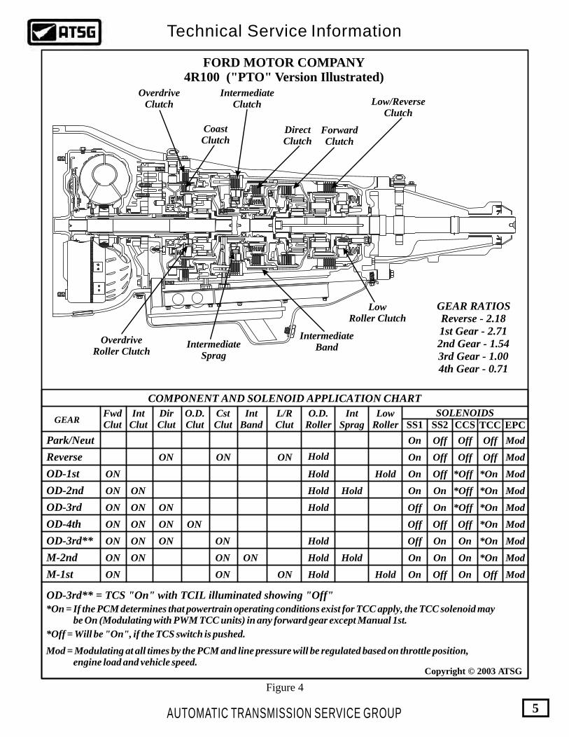
Digital Transmission Range Sensor
The Digital Transmission Range (DTR) sensor has a twelve pin electrical connector and is located on the outside of the transmission at the manual lever, as shown in Figure 12. The DTR sensor completes the start circuit in Park and Neutral, the backup lamp circuit in Reverse, and the neutral sense circuit (4WD Only) when in Neutral. The DTR sensor also opens or closes a set of four different switches that are monitored by the Powertrain Control Module (PCM) to determine the position of the transmission manual lever. Refer toFigure 13.
Figure 12
Ford
F7TP-7
F293-A
A
NEUTRAL LC
RFF81P-7006-BA
Ford
FordFord
98
XW4P-AC
RJL-B
004361
BD-9C17
In Figure 13 we have provided you with pin number identification for both the transmission range sensor and the vehicle harness. We have also provided a chart that will give you the open/closed state of each internal switch, dependent on selector position, and notice that three positions read a 270W resistor, that is also internal.
Note: All testing that we have provided for you is done with a DVOM, set to the ohms position, and all tests are performed with the ignition switch in the "OFF" position.
(1) Testing the transmission range 3A switch, and the 270W internal resistor is done across pins 2 and 3 of the DTR sensor, and must be checked in each selector position to determine the switch and resistor integrity. Refer to Figure 13.
(2) Testing the transmission range 1 switch is done across pins 2 and 4 of the DTR sensor, and must be checked in each selector position to determine switch integrity. Refer to Figure 13.
(3)
(4)
(5)
(6)
Testing the transmission range 2 switch is done across pins 2 and 5 of the DTR sensor, and must be checked in each selector position to determine switch integrity. Refer to Figure 13.
Testing the transmission range 4 switch is done across pins 2 and 6 of the DTR sensor, and must be checked in each selector position to determine switch integrity. Refer to Figure 13.
Testing the reverse lamp circuit is done across pins 9 and 11 of the DTR sensor, and must be checked in each selector position to determine switch integrity. Refer to Figure 13.
Testing the neutral start circuit is done across pins 10 and 12 of the DTR sensor, and must be checked in each selector position to determine switch integrity. Refer to Figure 13.
AUTOMATIC TRANSMISSION SERVICE GROUP
Technical Service Information
11
Copyright © 2003 ATSG
Figure 13
P R N 2 1TERMINALS
2 AND 3 CLOSED
CLOSED CLOSED CLOSED
CLOSED
CLOSED
CLOSED
CLOSEDCLOSED
CLOSED
CLOSED
CLOSED
OPEN
OPEN
OPEN
OPEN OPEN
OPEN OPEN
OPEN
OPEN
OPEN
OPEN
OPEN
OPEN
OPENOPEN
OPEN
OPEN
OPEN
CLOSED
CLOSED
CLOSED
2 AND 4
2 AND 5
2 AND 6
9 AND 11
10 AND 12
D
270 W270 W270 W
1 7
82
93
104
115
126
View looking into DTR Sensor
12 11 10 9 8
23456 1
7
View looking into DTR Sensorharness connector-terminal side
P 1
2R
N D
P 1
2R
N D
P 1
2R
N D
P 1
2R
N D
P 1
2R
N D
P 1
2R
N D 27
0 W
9 11 12 10 4 5 6 32
DIGITAL TRANSMISSION RANGE SENSOR
Pin No.
1
2
3
4
5
6
7
8
9
10
11
12
Pin No.Function
Not Used Ground
Neutral
Battery Voltage Feed
Fuse 21, Hot In Start
Back-up Lamps
Starter Relay
Signal Return (Ground)
TR3A (5 Volts from PCM)
TR1 (10-12 Volts from PCM)
TR2 (10-12 Volts from PCM)
TR4 (10-12 Volts from PCM)
Function

Only Motorcraft Mercon® multi-purpose automatictransmission fluid XT-2-QDX or an equivalent Mercon® fluid should be used in all Ford 4R100 transmissions. Before adding any fluid, ensure that it is the correct type.
Always use the transmission fluid level indicator (Dipstick) to set the correct fluid level. Set the fluid level at normal operating temperature which is 150° to 170°F, engine at idle in Park.
ELECTRICAL COMPONENT DIAGNOSIS SOLENOID PACK TESTING PROCEDURE
4R100 FLUID REQUIREMENTS
AUTOMATIC TRANSMISSION SERVICE GROUP
Technical Service Information
12
Copyright © 2003 ATSG
Solenoid Assembly
Checking Fluid
The Solenoid Assembly is bolted to the case and located inside the bottom pan. The Solenoid Assembly contains shift solenoid 1, shift solenoid 2, coast clutch solenoid, TCC solenoid, EPC solenoid and the TFT sensor. The solenoids are not serviced individually. You must replace the entire assembly, as shown in Figure 14. Some of these units are equipped with an ON/OFF TCC solenoid and some are equipped with a PWM TCC solenoid, so it is important to determine which you have.
Figure 15
Figure 14
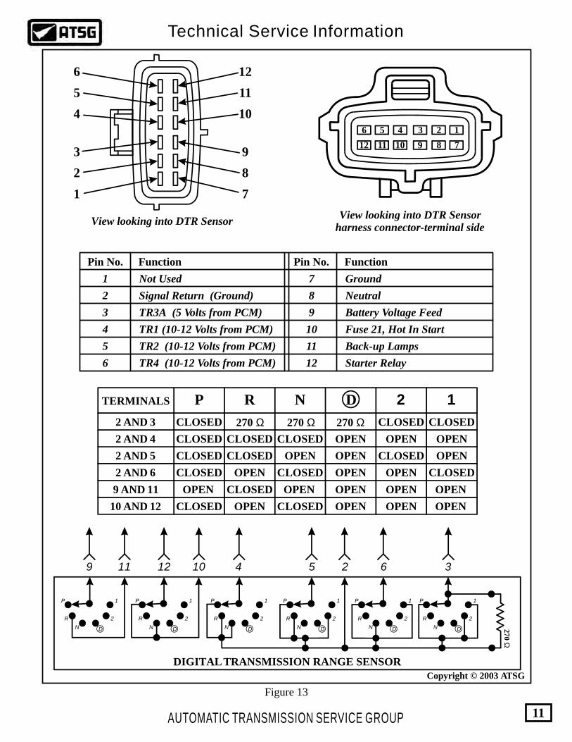
In Figure 16 we have provided you with pin number identification for both the transmission case connector and the vehicle harness. We have also provided a chart that will give you the function of each and the ohms readings you should see on each of the solenoids and the TFT sensor.
Note: All testing that we have provided for you is done with a DVOM, set to the ohms position, and all tests are performed with the ignition switch in the "OFF" position.
(1) Shift Solenoid 1 is tested across pins 1 and 3, and should read 20-30 ohms resistance. Refer to Figure 16.
Shift Solenoid 2 is tested across pins 1 and 2, and should read 20-30 ohms resistance. Refer to Figure 16.
Coast Clutch Solenoid is tested across pins 1 and 5, and should read 20-30 ohms resistance. Refer to Figure 16.
EPC Solenoid is tested across pins 11 and 12, and should read 3.0-5.0 ohms resistance. Refer to Figure 16.
TFT sensor is tested across pins 7 and 8. Refer to the chart provided in Figure 15.
TCC On/Off Solenoid is tested across pins 1 and 4, and should read 20-30 ohms resistance. Refer to Figure 16.
TCC PWM Solenoid is tested across pins 1 and 4, and should read 10-20 ohms resistance. Refer to Figure 16.
(2)
(3)
(4)
(5)
(6)
(7)
Transmission Fluid Temperature
°C °F Resistance
-40 to -20
-19 to -1
0 - 20
21-40
41-70
71-90
91-110
111-130
131-150 267-302
-40 to -4
-3 to 31
32-68
69-104
105-158
159-194
195-230
231-266
1062k - 284k W284k - 100k W100k - 37k W37k - 16k W16k - 5k W5k - 2.7k W
2.7k - 1.5k W1.5k - 0.8k W
0.8k - 0.54k W
SOLENOID PACK ASSEMBLY
AUTOMATIC TRANSMISSION SERVICE GROUP
Technical Service Information
13
Figure 16
Solenoid Connector Pin Identification and Function
Gas & Diesel (Cal) Diesel (49 State)
PCM Connector Pin
DescriptionPin No.
1
2
3
4
5
6
7
8
9
10
11
12
Vehicle Power In For Solenoids (VPWR)
Vehicle Power In For EPC Solenoid (VPWR)
Electronic Pressure Control (EPC)
Shift Solenoid "B" (2) Ground from PCM
Shift Solenoid "A" (1) Ground from PCM
Converter Clutch Solenoid Ground from PCM
Coast Clutch Solenoid Ground from PCM
Transmission Fluid Temp Sensor
Transmission Fluid Temp Sensor (Signal Return)
Not Used
Not Used
Not Used
71, 97
71, 97
11
6
54
20
37
91
81
1
27
28
53
37
91
81
71, 97
71, 97
SOLENOID BODYCONNECTOR
16 2345
121187
VEHICLE HARNESSCONNECTOR
1
12 7
6
SOLENOID BODY PIN IDENTIFICATION AND FUNCTION
Solenoid Resistance Chart
Solenoid BodyPin NumbersSolenoid
Shift Solenoid "B" (2) 1 and 2 20-30 Ohms
20-30 Ohms
20-30 Ohms
10-20 Ohms
20-30 Ohms
3.0-5.0 Ohms
See Chart Below
1 and 3
1 and 4
1 and 4
1 and 5
7 and 8
11 and 12
Shift Solenoid "A" (1)
TCC Solenoid, (On-Off)
TCC Solenoid, (PWM)
Coast Clutch Solenoid
Electronic Pressure Control Solenoid
Transmission Fluid Temp Sensor
Resistance
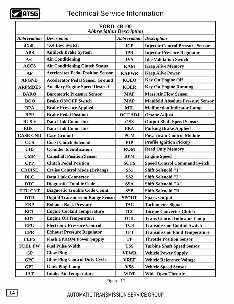
FORD 4R100Abbreviation Description
Abbreviation AbbreviationDescription Description
4X4L
ACCS
A/C
ABS
AP
APGND
ARPMDES
BARO
BOO
BPA
BPP
BUS -
BUS +
CCS
CASE GND
CPP
CMP
CID
CRUISE
DLC
DTC CNT
DTR
DTC
EBP
ECT
EOT
EPC
EPR
FUEL PW
FEPS
GPC
GP
GPL
IAT
ICP
IPR
IVS
KAM
KAPWR
KOEO
KOER
MAF
MAP
MIL
OCT ADJ
OSS
PCM
PBA
PIP
RPM
ROM
SCCS
SS1
SS2
SSA
SSB
SPOUT
TCC
TAC
TCIL
TCS
TFT
TP
TSS
VPWR
VREF
VSS
WOT
4X4 Low Switch
Antilock Brake System
Air Conditioning Clutch Status
Air Conditioning
Accelerator Pedal Position Sensor
Accelerator Pedal Sensor Ground
Ancillary Engine Speed Desired
Barometric Pressure Sensor
Brake ON/OFF Switch
Brake Pressure Applied
Brake Pedal Position
Data Link Connector
Data Link Connector
Coast Clutch Solenoid
Case Ground
Clutch Pedal Position
Camshaft Position Sensor
Cylinder Identification
Cruise Control Mode (Driving)
Data Link Connector
Diagnostic Trouble Code Count
Diagnostic Trouble Code
Digital Transmission Range Sensor
Exhaust Back Pressure
Engine Coolant Temperature
Exhaust Pressure Regulator
Fuel Pulse Width
Flash EPROM Power Supply
Glow Plug Control Duty Cycle
Glow Plug
Intake Air Temperature
Glow Plug Lamp
Injector Control Pressure Sensor
Injector Pressure Regulator
Idle Validation Switch
Keep Alive Memory
Keep Alive Power
Key On Engine Off
Key On Engine Running
Mass Air Flow Sensor
Manifold Absolute Pressure Sensor
Malfunction Indicator Lamp
Octane Adjust
Output Shaft Speed Sensor
Powertrain Control Module
Parking Brake Applied
Profile Ignition Pickup
Engine Speed
Read Only Memory
Speed Control Command Switch
Shift Solenoid "1"
Shift Solenoid "2"
Shift Solenoid "A"
Shift Solenoid "B"
Spark Output
Torque Converter Clutch
Tachometer Signal
Trans Control Indicator Lamp
Transmission Control Switch
Transmission Fluid Temperature
Throttle Position Sensor
Turbine Shaft Speed Sensor
Vehicle Power Supply
Vehicle Reference Voltage
Vehicle Speed Sensor
Wide Open Throttle
Engine Oil Temperature
Electronic Pressure Control
Figure 17
AUTOMATIC TRANSMISSION SERVICE GROUP
Technical Service Information
14
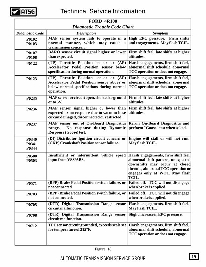
Diagnostic Trouble Code Chart
Diagnostic Code Description Symptom
P0102P0103
P0107P0108
P0122
P0123
P0235
P0236
P0237
P0340P0341P0344
P0500P0503
P0571
P0703
P0705
P0708
P0712
MAF sensor system fails to operate in a normal manner, which may cause a transmission concern.
High EPC pressure. Firm shifts and engagements. May flash TCIL.
BARO sensor circuit signal higher or lower than expected.
Firm shift feel, late shifts at higher altitudes.
Firm shift feel, late shifts at higher altitudes.
Firm shift feel, late shifts at higher altitudes.
(TP) Throttle Position sensor or (AP) Accelerator Pedal Position sensor below specification during normal operation.
(TP) Throttle Position sensor or (AP) Accelerator Pedal Position sensor above or below normal specifications during normal operation.
Harsh engagements, firm shift feel, abnormal shift schedule, abnormal TCC operation or does not engage.
Harsh engagements, firm shift feel, abnormal shift schedule, abnormal TCC operation or does not engage.
Harsh engagements, firm shift feel, abnormal shift schedule, abnormal TCC operation or does not engage.
MAP sensor or circuit open, shorted to ground or to 5V.
MAP sensor signal higher or lower than expected or no response due to vacuum hose circuit damaged, disconnected or restricted.
MAP sensor out of On-Board Diagnostics range. No response during Dynamic Response (Goose) test.
Rerun On-Board Diagnostics and perform "Goose" test when asked.
(DI) Distributor Ignition circuit concern or (CKP) Crankshaft Position sensor failure.
Engine will stall or will not run. May flash TCIL.
Insufficient or intermittent vehicle speed input from VSS/ABS.
Harsh engagements, firm shift feel, abnormal shift pattern, unexpected downshifts may occur at closed throttle, abnormal TCC operation or engages only at WOT. May flash TCIL.
(BPP) Brake Pedal Position switch failure, or not connected.
(BPP) Brake Pedal Position switch failure, or not connected.
Failed off. TCC will not disengage when brake is applied.
Failed off. TCC will not disengage when brake is applied.
(DTR) Digital Transmission Range sensor circuit malfunction.
(DTR) Digital Transmission Range sensor circuit malfunction.
Harsh engagements, firm shift feel. May flash TCIL.
Slight increase in EPC pressure.
TFT sensor circuit grounded, exceeds scale set for temperature of 315°F.
FORD 4R100
Figure 18
AUTOMATIC TRANSMISSION SERVICE GROUP
Technical Service Information
15

Diagnostic Trouble Code Chart
Diagnostic Code Description Symptom
P0713
P0715
P0717
P0718
P0720
P0721
P0722
P0731
P0732
P0733
P0741
P0743
P0750
P0755
TFT sensor circuit open, exceeds scale set for temperature of minus 40°F.
TCC and stabilized shift schedule may be enabled sooner after cold start. May flash TCIL.
Insufficient input from TSS sensor.
Insufficient input from OSS sensor.
TSS sensor signal intermittent.
OSS sensor signal intermittent.
TSS sensor signal noisy.
OSS sensor signal noisy.
Set DTC, Flash TCIL and Flash MIL.
Set DTC, Flash TCIL and Flash MIL.
Set DTC, Flash TCIL.
Set DTC, Flash TCIL.
Set DTC.
Set DTC.
1-2 shift error because of SSA, SSB, or internal transmission components.
2-3 shift error because of SSA, SSB, or internal transmission components.
3-4 shift error because of SSA, SSB, or internal transmission components.
Improper gear selection depending on failure mode and transmission range selector position. Refer to shift solenoid operation chart.
Improper gear selection depending on failure mode and transmission range selector position. Refer to shift solenoid operation chart.
Improper gear selection depending on failure mode and transmission range selector position. Refer to shift solenoid operation chart.
Improper gear selection depending on failure mode and transmission range selector position. Refer to shift solenoid operation chart.
Improper gear selection depending on failure mode and transmission range selector position. Refer to shift solenoid operation chart.
The PCM picked up an excessive amount of TCC slippage during normal operation.
TCC slippage/erratic or no torque converter clutch operation. Flash TCIL.
TCC Solenoid circuit failure.
SSA circuit failure.
SSB circuit failure.
Short Circuit: Engine stalls in "D" or "2" at idle with brake applied. Open Circuit: TCC never engaged.
FORD 4R100
Figure 19
AUTOMATIC TRANSMISSION SERVICE GROUP
Technical Service Information
16

Diagnostic Trouble Code Chart
Diagnostic Code Description Symptom
P0781
P0782
P0783
P1100P1101
P1111
P1120
P1124
P1280
P1281
P1500
P1460P1463P1464
1-2 shift error because of SSA, SSB, or internal transmission components.
2-3 shift error because of SSA, SSB, or internal transmission components.
3-4 shift error because of SSA, SSB, or internal transmission components.
Throttle Position Sensor voltage lower than expected.
Throttle Position Sensor out of On-Board Diagnostics range during KOEO test.
A/C switch error.
Injection Control Pressure (ICP) sensor circuit failure (Diesel Engine), or out of range low.
Injection Control Pressure (ICP) sensor circuit failure (Diesel Engine), or out of range high.
System Pass. No Codes Detected.
May result in firm shifts.
May result in firm shifts.
Improper gear selection depending on failure mode and transmission range selector position. Refer to shift solenoid operation chart.
Improper gear selection depending on failure mode and transmission range selector position. Refer to shift solenoid operation chart.
Improper gear selection depending on failure mode and transmission range selector position. Refer to shift solenoid operation chart.
MAF sensor system fails to operate in a normal manner, which may cause a transmission concern.
High EPC pressure. Firm shifts and engagements. May flash TCIL.
Harsh engagements, firm shift feel, abnormal shift schedule, abnormal TCC operation or does not engage.
Failed On: EPC pressure slightly low with A/C off.Failed Off: EPC pressure slightly low with A/C on.
TP sensor (Gas Engines) not at idle position during KOEO test.
Insufficient or intermittent vehicle speed input from VSS/ABS.
Harsh engagements, firm shift feel, abnormal shift pattern, unexpected downshifts may occur at closed throttle, abnormal TCC operation or engages only at WOT. May flash TCIL.
FORD 4R100
Figure 20
AUTOMATIC TRANSMISSION SERVICE GROUP
Technical Service Information
17

Diagnostic Trouble Code Chart
Diagnostic Code Description Symptom
P1702
P1703
P1704
P1705
P1711
P1713
P1718
P1728
P1729
P1740
P1744
P1746
P1747
P1714
P1715
Digital Transmission Range (DTR) sensor signal intermittent.
Digital Transmission Range (DTR) sensor misaligned or failed electronically.
Digital Transmission Range (DTR) sensor not run in park or neutral during On-Board Diagnostics KOEO or KOER tests.
Excessive amount of transmission slippage has been detected.
4X4 Low switch circuit failure.
Transmission not at operating temperature during On-Board Diagnostics.
No change in TFT sensor - Low range.
No change in TFT sensor - High range.
SSA mechanical failure detected.
SSB mechanical failure detected.
TCC solenoid mechanical failure detected.
Erratic harsh shift engagements.
Increase in EPC pressure.
Rerun On-Board Diagnostics.
May flash TCIL.
May flash TCIL.
Early or delayed shift schedule.
Harsh shift, may flash TCIL.
Warm vehicle to normal operating temperature and rerun On-Board Diagnostics.
(BPP) Brake Pedal Position switch not actuated during KOER test.
Failed on or not connected, TCC will not engage at less than one-third throttle opening.
Improper gear selection depending on failure mode and transmission range selector position. Refer to shift solenoid operation chart.
Transmission slippage, erratic or no TCC operation. May flash TCIL.
Improper gear selection depending on failure mode and transmission range selector position. Refer to shift solenoid operation chart.
Open circuit causes maximum EPC pressure, harsh engagements and shifts. May flash TCIL.
Shorted circuit causes minimum EPC pressure, limits engine torque with partial fuel shut off and heavy misfire. Flashing TCIL.
The PCM picked up an excessive amount of TCC slippage during normal operation.
Failure of the EPC control pressure driver located inside the PCM.
TCC slippage/erratic or no torque converter clutch operation. Flash TCIL.
EPC shorted circuit failure, or PCM.
FORD 4R100
Figure 21
AUTOMATIC TRANSMISSION SERVICE GROUP
Technical Service Information
18
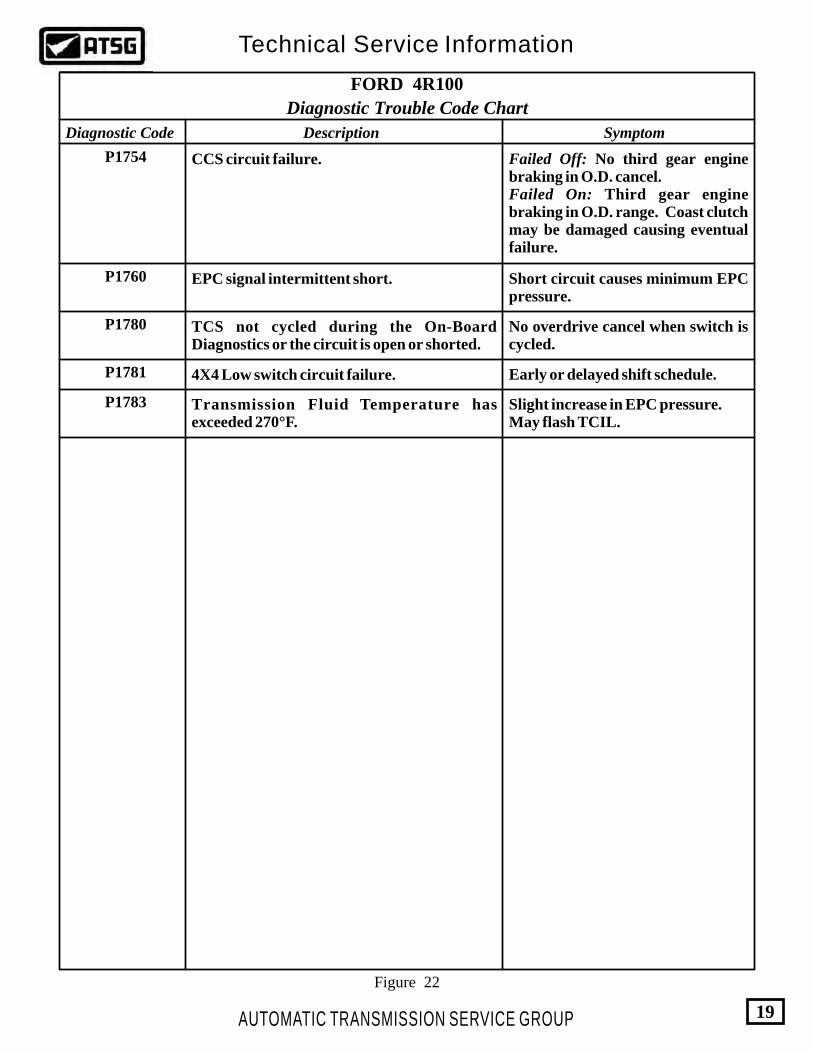
Diagnostic Trouble Code Chart
Diagnostic Code Description Symptom
P1754
P1760
P1780
P1781
P1783
CCS circuit failure.
EPC signal intermittent short.
TCS not cycled during the On-Board Diagnostics or the circuit is open or shorted.
Transmission Fluid Temperature has exceeded 270°F.
Failed Off: No third gear engine braking in O.D. cancel.Failed On: Third gear engine braking in O.D. range. Coast clutch may be damaged causing eventual failure.
Short circuit causes minimum EPC pressure.
No overdrive cancel when switch is cycled.
4X4 Low switch circuit failure. Early or delayed shift schedule.
Slight increase in EPC pressure.May flash TCIL.
FORD 4R100
Figure 22
AUTOMATIC TRANSMISSION SERVICE GROUP
Technical Service Information
19

Figure 23
AUTOMATIC TRANSMISSION SERVICE GROUP
Technical Service Information
20
Shift Solenoid Application Chart
Selector LeverRange
CommandedGear
ShiftSolenoid "B"
ShiftSolenoid "A"
TCCSolenoid
Coast ClutchSolenoid
P/R/N 1
1
2
2MANUAL 2
MANUAL 1
MANUAL 1
2
1
3
4
ON
ON
ON
ON
ON
ON
ON
ON
ON
OFF
OFF
OFF
OFF
OFF OFF
OFF
OFF
OFF
OFF
D
D
D
D
DCancel
First Through 3rd Gear Only, SSA, SSB, TCC, Same as Overdrive, CCS Always On.
* ** ** ** **
***
*
*
Controlled by PCM
D
Selector Lever Position
Actual Gear ObtainedPCM Gear
Commanded
2 1
1st
2nd
3rd
4th
SHIFT SOLENOID "A" ALWAYS OFF
4
4
3
3
2
2
2
2 2
2
2
1
D
Selector Lever Position
Actual Gear ObtainedPCM Gear
Commanded
2 1
1st
2nd
3rd
4th
SHIFT SOLENOID "B" ALWAYS ON
2
2
2 2
2
2
2
2
3
3
1
1
D
Selector Lever Position
Actual Gear ObtainedPCM Gear
Commanded
2 1
1st
2nd
3rd
4th
SHIFT SOLENOID "A" ALWAYS ON
2
2
2
2
2
2
1
1
1
1
1
1
D
Selector Lever Position
Actual Gear ObtainedPCM Gear
Commanded
2 1
1st
2nd
3rd
4th
SHIFT SOLENOID "B" ALWAYS OFF
4
4
2
2
2
2 2
2
1 1
11
SHIFT SOLENOID TROUBLE CHART GUIDE

AUTOMATIC TRANSMISSION SERVICE GROUP
Technical Service Information
21
Copyright © 2003 ATSG
RFF81P-7006-BA
Ford
FordFord
98
XW4P-AC
RJL-B
004361
BD-9C17
lllll ll ll ll ll ll ll ll ll ll ll ll ll ll ll ll ll ll llll llll ll
LINE PRESSURE SPECIFICATION CHART
LINE PRESSURE TEST
LINE PRESSURE TEST
Gear
P, N
R
M1
OD, M2
Idle
50-65 psi
50-65 psi
70-100 psi
70-115 psi
220-240 psi
136-156 psi
175-210 psi
Stall NOTE: On vehicles equipped with PTO units, access to the line pressure port may require that you remove the PTO unit depending on the type of unit installed. If required, remove the PTO unit and install PTO cover and gasket "Before" doing the line pressure test.
Figure 24
NOTE: Perform the line pressure test before performing the "Stall" test. If the line pressure is low at "Idle", DO NOT perform the "Stall" test or further transmission damage will occur.Do Not Maintain Wide Open Throttle in any gear range for more than "5 Seconds" or transmission damage may occur.
NOTE: If equipped, turn "Off" the PTO unit to ensure proper test results.
1. Install a 300 psi line pressure gauge to the line pressure tap, as shown in Figure 24. 2. Start the engine and check line pressure in all ranges at "Idle". Refer to the chart shown in Figure 24 to determine if they are within the specifications. 3. If the line pressures are within the specifications at "Idle", now you can perform the "Stall" test to determine if specifications are okay there. 4. Once again, refer to the chart in Figure 24, to determine proper specifications at "Stall".
CHANGE:
REASON:
PARTS AFFECTED:
INTERCHANGEABILITY:
SERVICE INFORMATION:
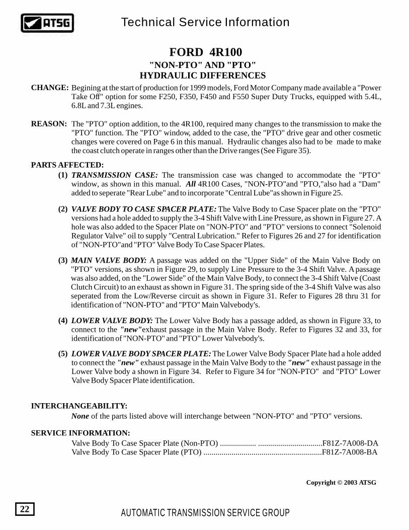
Begining at the start of production for 1999 models, Ford Motor Company made available a "Power Take Off" option for some F250, F350, F450 and F550 Super Duty Trucks, equipped with 5.4L, 6.8L and 7.3L engines.
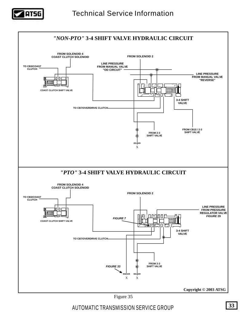
The "PTO" option addition, to the 4R100, required many changes to the transmission to make the "PTO" function. The "PTO" window, added to the case, the "PTO" drive gear and other cosmetic changes were covered on Page 6 in this manual. Hydraulic changes also had to be made to make the coast clutch operate in ranges other than the Drive ranges (See Figure 35).
TRANSMISSION CASE: The transmission case was changed to accommodate the "PTO" window, as shown in this manual. All 4R100 Cases, "NON-PTO"and "PTO,"also had a "Dam" added to seperate "Rear Lube" and to incorporate "Central Lube"as shown in Figure 25.
VALVE BODY TO CASE SPACER PLATE: The Valve Body to Case Spacer plate on the "PTO" versions had a hole added to supply the 3-4 Shift Valve with Line Pressure, as shown in Figure 27. A hole was also added to the Spacer Plate on "NON-PTO" and "PTO" versions to connect "Solenoid Regulator Valve" oil to supply "Central Lubrication." Refer to Figures 26 and 27 for identification of "NON-PTO"and "PTO" Valve Body To Case Spacer Plates.
MAIN VALVE BODY: A passage was added on the "Upper Side" of the Main Valve Body on "PTO" versions, as shown in Figure 29, to supply Line Pressure to the 3-4 Shift Valve. A passage was also added, on the "Lower Side" of the Main Valve Body, to connect the 3-4 Shift Valve (Coast Clutch Circuit) to an exhaust as shown in Figure 31. The spring side of the 3-4 Shift Valve was also seperated from the Low/Reverse circuit as shown in Figure 31. Refer to Figures 28 thru 31 for identification of "NON-PTO" and "PTO" Main Valvebody's.
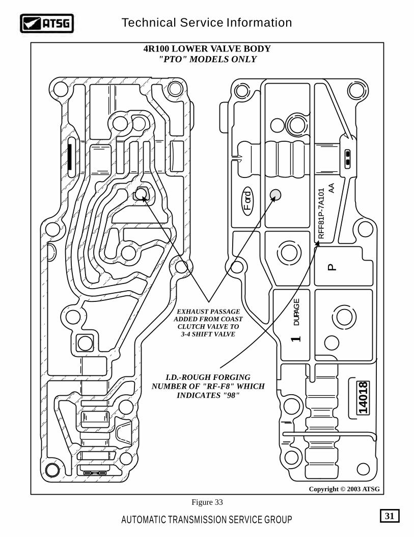
LOWER VALVE BODY: The Lower Valve Body has a passage added, as shown in Figure 33, to connect to the "new"exhaust passage in the Main Valve Body. Refer to Figures 32 and 33, for identification of "NON-PTO" and "PTO" Lower Valvebody's.
LOWER VALVE BODY SPACER PLATE: The Lower Valve Body Spacer Plate had a hole added to connect the "new" exhaust passage in the Main Valve Body to the "new" exhaust passage in the Lower Valve body a shown in Figure 34. Refer to Figure 34 for "NON-PTO" and "PTO" Lower Valve Body Spacer Plate identification.
None of the parts listed above will interchange between "NON-PTO" and "PTO" versions.
(1)
(2)
(3)
(4)
(5)
Valve Body To Case Spacer Plate (Non-PTO) .................. ................................F81Z-7A008-DAValve Body To Case Spacer Plate (PTO) ...........................................................F81Z-7A008-BA
FORD 4R100"NON-PTO" AND "PTO"
HYDRAULIC DIFFERENCES
AUTOMATIC TRANSMISSION SERVICE GROUP
Technical Service Information
22
Copyright © 2003 ATSG
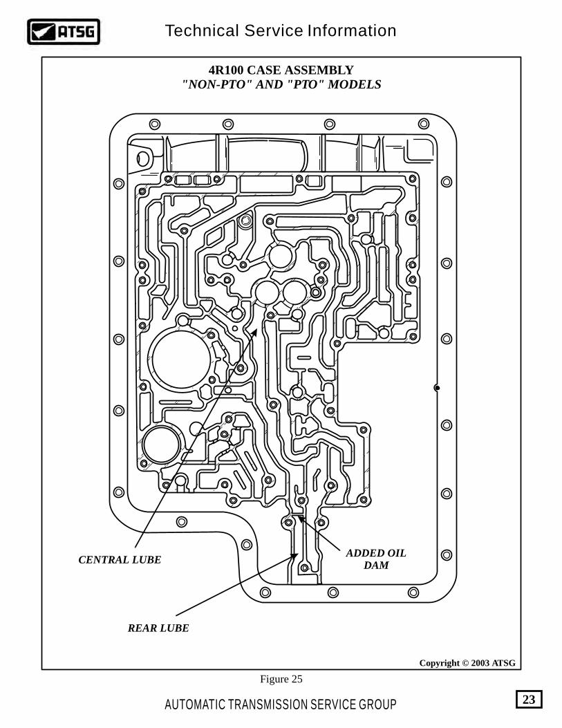
REAR LUBE
ADDED OILDAM
CENTRAL LUBE
4R100 CASE ASSEMBLY"NON-PTO" AND "PTO" MODELS
Figure 25
AUTOMATIC TRANSMISSION SERVICE GROUP
Technical Service Information
23
Copyright © 2003 ATSG
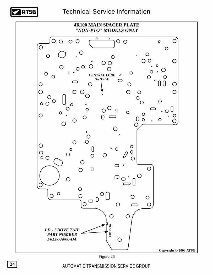
Figure 26
4R100 MAIN SPACER PLATE"NON-PTO" MODELS ONLY
F81P
-DA
F81P
-DA
97
97
12
12
CENTRAL LUBEORIFICE
I.D.- 1 DOVE TAILPART NUMBERF81Z-7A008-DA
AUTOMATIC TRANSMISSION SERVICE GROUP
Technical Service Information
24
Copyright © 2003 ATSG

ADDED MAIN LINE PRESSURE HOLEFROM PRESSURE REGULATOR VALVE
F81P
-BA
F81P
-BA
98
9866
CENTRAL LUBEORIFICE
4R100 MAIN SPACER PLATE"PTO" MODELS ONLY
I.D.- 2 DOVE TAILSPART NUMBERF81Z-7A008-BA
Figure 27
AUTOMATIC TRANSMISSION SERVICE GROUP
Technical Service Information
25
Copyright © 2003 ATSG

"UPPER SIDE" 4R100 MAIN VALVE BODY"NON-PTO" MODELS ONLY
Figure 28
AUTOMATIC TRANSMISSION SERVICE GROUP
Technical Service Information
26
Copyright © 2003 ATSG

"UPPER SIDE" 4R100 MAIN VALVE BODY"PTO" MODELS ONLY
Figure 29
PASSAGE ADDED TOFEED LINE PRESSURE TO
THE 3-4 SHIFT VALVE
AUTOMATIC TRANSMISSION SERVICE GROUP
Technical Service Information
27
Copyright © 2003 ATSG

"LOWER SIDE" 4R100 MAIN VALVE BODY"NON-PTO" MODELS ONLY
Figure 30
Ford
Ford
RF
F61P
-7A
092-A
BR
FF
61P
-7A
092-A
B
Du Pa
ge
Du Pa
ge
09
32
80
93
28
66
I.D.-ROUGH FORGINGNUMBER OF "RF-F6" WHICH
INDICATES "96"
LOW/REVERSECLUTCH
AUTOMATIC TRANSMISSION SERVICE GROUP
Technical Service Information
28
Copyright © 2003 ATSG

Ford
Ford
RF
F8
1P
-7
A0
92
-AA
RF
F8
1P
-7
A0
92
-AA
Du Pa
ge
Du Pa
ge
19
53
81
95
38
11PP
I.D.-ROUGH FORGINGNUMBER OF "RF-F8" WHICH
INDICATES "98"
PASSAGE ADDEDLEADING TO THEEXHAUST IN THE
LOWER VALVE BODY
LOW/REVERSEPASSAGE RE-MOVEDFROM SPRING SIDEOF 3-4 SHIFT VALVE
"LOWER SIDE" 4R100 MAIN VALVE BODY"PTO" MODELS ONLY
Figure 31
LOW/REVERSECLUTCH
AUTOMATIC TRANSMISSION SERVICE GROUP
Technical Service Information
29
Copyright © 2003 ATSG

RF
F61P
-7A
101
RF
F61P
-7A
101 AA
09
82
80
98
28
55D
u P
ag
eD
u P
ag
e
For
dF
ord
4R100 LOWER VALVE BODY"NON-PTO" MODELS ONLY
Figure 32
I.D.-ROUGH FORGINGNUMBER OF "RF-F6" WHICH
INDICATES "96"
AUTOMATIC TRANSMISSION SERVICE GROUP
Technical Service Information
30
Copyright © 2003 ATSG
RF
F81P
-7A
101
RF
F81P
-7A
101 AA
AA
PP
14018
14018
11D
UPA
GE
DU
PAG
E
For
dF
ord
4R100 LOWER VALVE BODY"PTO" MODELS ONLY
EXHAUST PASSAGEADDED FROM COAST
CLUTCH VALVE TO 3-4 SHIFT VALVE
Figure 33
I.D.-ROUGH FORGINGNUMBER OF "RF-F8" WHICH
INDICATES "98"
AUTOMATIC TRANSMISSION SERVICE GROUP
Technical Service Information
31
Copyright © 2003 ATSG

"PTO" MODELS ONLY"NON-PTO" MODELS ONLY
4R100 LOWER VALVE BODY SPACER PLATE
Figure 34
HOLE ADDED TO CONNECT WITH EXHAUST PASSAGE IN LOWER VALVE BODY
I.D.- 1 DOVE TAIL I.D.- 2 DOVE TAILS
AUTOMATIC TRANSMISSION SERVICE GROUP
Technical Service Information
32
Copyright © 2003 ATSG
3-4 SHIFTVALVE
3-4 SHIFTVALVE
FIGURE 33
FIGURE 7
LINE PRESSUREFROM PRESSURE
REGULATOR VALVEFIGURE 29
LINE PRESSUREFROM MANUAL VALVE
"REVERSE"
LINE PRESSUREFROM MANUAL VALVE
"OD CIRCUIT"
FROM SOLENOID 2
FROM SOLENOID 2
FROM SOLENOID 4COAST CLUTCH SOLENOID
FROM SOLENOID 4COAST CLUTCH SOLENOID
FROM 2-3SHIFT VALVE
FROM 2-3SHIFT VALVE
FROM CB15 / 2-3SHIFT VALVE
TO CB3/COASTCLUTCH
TO CB3/COASTCLUTCH
TO CB7/OVERDRIVE CLUTCH
TO CB7/OVERDRIVE CLUTCH
X X
X
COAST CLUTCH SHIFT VALVE
COAST CLUTCH SHIFT VALVE
"NON-PTO" 3-4 SHIFT VALVE HYDRAULIC CIRCUIT
"PTO" 3-4 SHIFT VALVE HYDRAULIC CIRCUIT
Figure 35
AUTOMATIC TRANSMISSION SERVICE GROUP
Technical Service Information
33
Copyright © 2003 ATSG

FORD 4R100"PWM" AND "NON-PWM"
PUMP DIFFERENCES
CHANGE:
REASON:
PARTS AFFECTED:
SERVICE INFORMATION:
INTERCHANGABILITY:
Beginning at the start of production in 1999, the 4R100 transmission was offered with two different torque converter clutch application strategies. A "PWM" (Pulse Width Modulated) version, was added for V-10 gas powered vehicles and all diesels, and a "NON-PWM" version, offered in all other gas powered vehicles. This required two different solenoid packs as well as two different pump assemblies.
For smooth converter clutch apply on V-10 gas and diesel engine models.
PUMP ASSEMBLY: The pump cover assembly had the rear of the Converter Clutch Valve bore enlarged approximately .070" to accommodate the enlarged land of the Converter Clutch Valve as shown in Figure 36.A .036" orifice and an air bleed were added to the TCC Solenoid signal passage as shown in Figure 38.The Converter Clutch Control Valve's rear spool was enlarged approximately .070." There was also a bushing and valve added to the end of the valve train as shown in Figure 36.A hole was added to the pump cover to connect the Converter Clutch Control Valve Bushing to Converter Regulator Valve oil, as shown in Figure 38.The Converter release orifice in the NON-PWM pump cover, as shown in Figure 37, was removed from the PWM pump cover as shown in Figure 38.
THE SOLENOID PACK:The PWM solenoid pack requires a Pulse Width Modulated torque converter clutch solenoid and the NON-PWM solenoid pack requires an on-off torque converter clutch solenoid.
(1)
(2)
•
•
•
•
•
•
"NON-PWM" Pump assy. (with "Cast Iron" coast clutch drum).................F81Z-7A103-AA"NON-PWM" Pump assy. (with "Stamped Steel" coast clutch drum)..........F81Z-7A103-BA"PWM" Pump assy. (with "Stamped Steel" coast clutch drum)....................F81Z-7A103-CA"NON-PWM" Solenoid Pack...........................................................................F81Z-7G391-BA"PWM" Solenoid Pack.....................................................................................F81Z-7G391-AB
None of the parts listed above are interchangable from model to model.
AUTOMATIC TRANSMISSION SERVICE GROUP
Technical Service Information
34
Copyright © 2003 ATSG

CONVERTER CLUTCH CONTROL VALVE
"NON-PWM" "PWM"
.600".530"
.485" .545"
THE DIAMETER AND THE LENGTH OF THE SPOOL ON THE VALVE LAND SHOWN ABOVE,WERE INCREASED ON PWM VERSIONS. THE BORE IN THE PUMP COVER WAS ALSO ENLARGED
APPROXIMATELY .070" TO ACOMMODATE THE CHANGES IN THE DIAMETER OF THE VALVE
Figure 36
AUTOMATIC TRANSMISSION SERVICE GROUP
Technical Service Information
35
Copyright © 2003 ATSG

4R100 PUMP COVER ASSEMBLY"NON-PWM" MODELS ONLY
LUBE ORIFICE.090"
CONVERTER RELEASEORIFICE .070"
CONVERTER REGULATORVALVE
CONVERTER CLUTCHCONTROL VALVE PRESSURE REGULATOR
VALVE
RETAINER
Figure 37
AUTOMATIC TRANSMISSION SERVICE GROUP
Technical Service Information
36
Copyright © 2003 ATSG

4R100 PUMP COVER ASSEMBLY"PWM" MODELS ONLY
LUBE ORIFICE.090"
ADDED ORIFICE INTCC PWM SOLENOID
SIGNAL PASSAGE.036"
ADDED AIRBLEED
CONVERTER RELEASEORIFICE OMITTED
HOLE ADDED TOCONNECT TO HOLE IN
CONTROL VALVE BUSHING
CONVERTER REGULATORVALVE
CONVERTER CLUTCHCONTROL VALVE
PRESSURE REGULATORVALVE
RETAINER
Figure 38
AUTOMATIC TRANSMISSION SERVICE GROUP
Technical Service Information
37
Copyright © 2003 ATSG

4R100 CASE CHECKBALL LOCATIONS"NON-PTO" AND "PTO" MODELS
Figure 39
CB14CB9CB1 CB6
BS3 BS1
CB7 CB8
EPC BallAnd Spring
Requires Eight 5/16" Diameter Rubber CheckballsPlus The EPC Ball And Spring, As Shown Above.
AUTOMATIC TRANSMISSION SERVICE GROUP
Technical Service Information
38
Copyright © 2003 ATSG
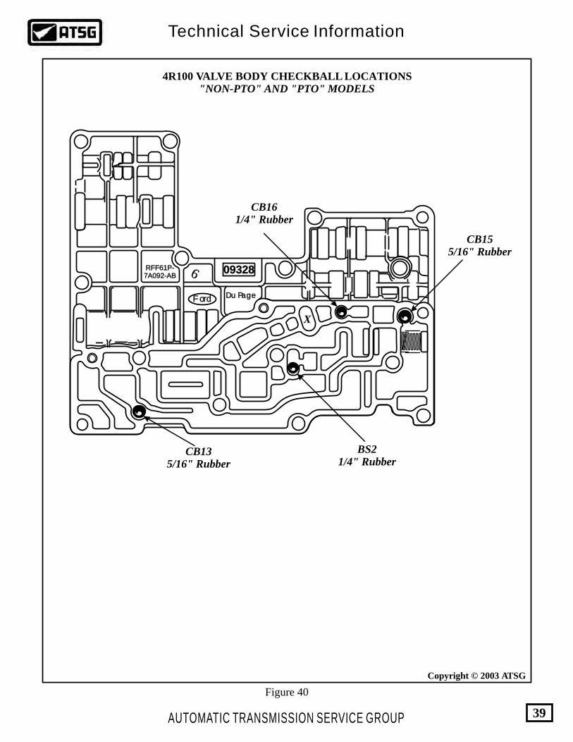
Figure 40
FordFord
RFF61P-7A092-ABRFF61P-7A092-AB
Du PageDu Page
093280932866
CB161/4" Rubber
CB155/16" Rubber
X
CB135/16" Rubber
BS21/4" Rubber
4R100 VALVE BODY CHECKBALL LOCATIONS"NON-PTO" AND "PTO" MODELS
AUTOMATIC TRANSMISSION SERVICE GROUP
Technical Service Information
39
Copyright © 2003 ATSG

AUTOMATIC TRANSMISSION SERVICE GROUP
Technical Service Information
40
Copyright © 2003 ATSG
Copyright © 2003 ATSG
Low/ReverseClutch
IntermediateClutch
IntermediateLube
OverdriveClutch
CoastClutch
ForwardClutch
DirectClutch
AIR PRESSURE CHECKS
Figure 41
Figure 42
RFF81P-7006-BA
Ford
Ford
98
XW4P-AC
RJL-B
004361
BD-9C17
AUTOMATIC TRANSMISSION SERVICE GROUP
Technical Service Information
41
Copyright © 2003 ATSG
Copyright © 2003 ATSG
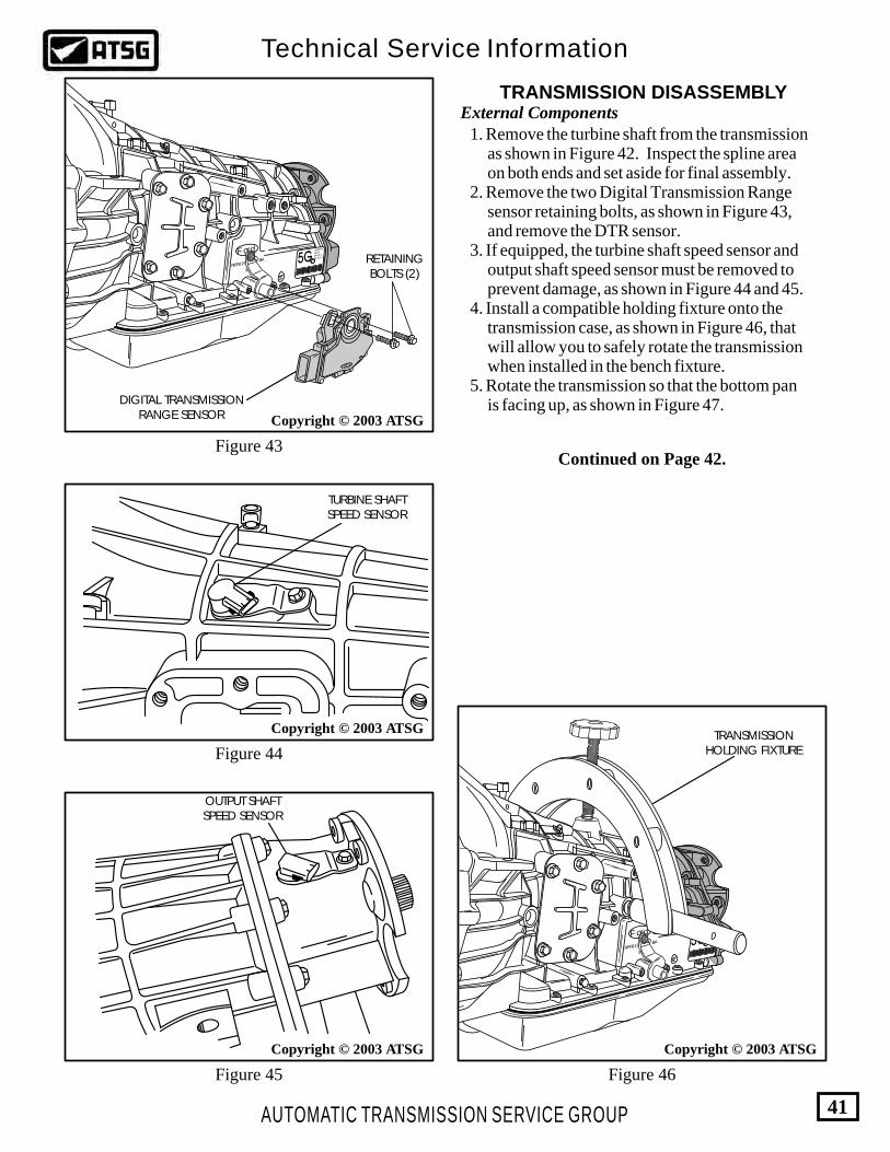
TRANSMISSION DISASSEMBLYExternal Components
RFF81P-7006-BA
Ford
98
XW4P-AC
RJL-B
004361
BD-9C17
Ford
Figure 43
Copyright © 2003 ATSG
Copyright © 2003 ATSG
Figure 44
Figure 45 Figure 46
DIGITAL TRANSMISSIONRANGE SENSOR
RETAININGBOLTS (2)
TURBINE SHAFTSPEED SENSOR
OUTPUT SHAFTSPEED SENSOR
TRANSMISSIONHOLDING FIXTURE
RFF81P-7006-BA
Ford
98
XW4P-AC
RJL-B
004361
BD-9C17
1. Remove the turbine shaft from the transmission as shown in Figure 42. Inspect the spline area on both ends and set aside for final assembly. 2. Remove the two Digital Transmission Range sensor retaining bolts, as shown in Figure 43, and remove the DTR sensor. 3. If equipped, the turbine shaft speed sensor and output shaft speed sensor must be removed to prevent damage, as shown in Figure 44 and 45. 4. Install a compatible holding fixture onto the transmission case, as shown in Figure 46, that will allow you to safely rotate the transmission when installed in the bench fixture. 5. Rotate the transmission so that the bottom pan is facing up, as shown in Figure 47.
Continued on Page 42.
6262
U P
AUTOMATIC TRANSMISSION SERVICE GROUP
Technical Service Information
42
Copyright © 2003 ATSG
Copyright © 2003 ATSG Copyright © 2003 ATSG
Figure 48 Figure 49
Figure 47
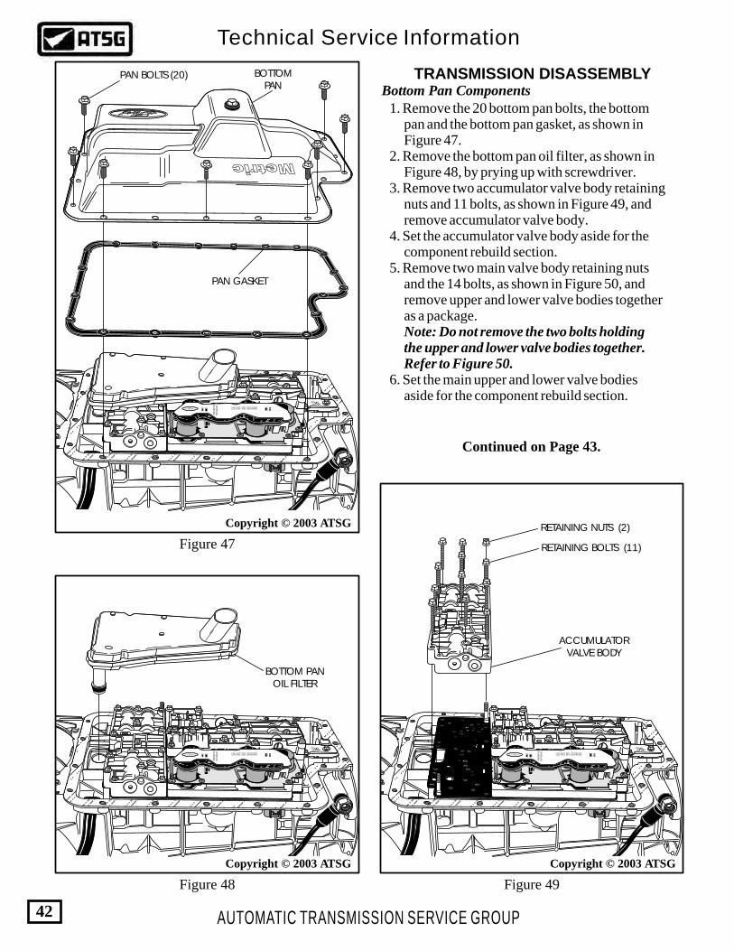
TRANSMISSION DISASSEMBLYBottom Pan Components 1. Remove the 20 bottom pan bolts, the bottom pan and the bottom pan gasket, as shown in Figure 47. 2. Remove the bottom pan oil filter, as shown in Figure 48, by prying up with screwdriver. 3. Remove two accumulator valve body retaining nuts and 11 bolts, as shown in Figure 49, and remove accumulator valve body. 4. Set the accumulator valve body aside for the component rebuild section. 5. Remove two main valve body retaining nuts and the 14 bolts, as shown in Figure 50, and remove upper and lower valve bodies together as a package. Note: Do not remove the two bolts holding the upper and lower valve bodies together. Refer to Figure 50. 6. Set the main upper and lower valve bodies aside for the component rebuild section.
6262
U P
6262
U P
PAN BOLTS (20) BOTTOMPAN
PAN GASKET
ACCUMULATORVALVE BODY
RETAINING NUTS (2)
RETAINING BOLTS (11)
BOTTOM PANOIL FILTER
Continued on Page 43.

6262
U P
6262
U P
6262
U P
AUTOMATIC TRANSMISSION SERVICE GROUP
Technical Service Information
43
Figure 50 Figure 52
Figure 51
RETAININGBOLTS (9)
SOLENOIDBODY ASSEMBLY
"O" RING
UPPER AND LOWERMAIN VALVE BODIES
DO NOT REMOVETHESE TWO BOLTS
Continued on Page 44.
Copyright © 2003 ATSG Copyright © 2003 ATSG
Copyright © 2003 ATSG
RETAINING BOLTS (14)
RETAINING NUTS (2)
187
186
RETAINING NUT
186 SPACER PLATE TO MAIN VALVE BODY GASKET 187 SOLENOID SCREEN ASSEMBLY
TRANSMISSION DISASSEMBLYBottom Pan Components 7. Remove the solenoid body retaining nut and the 9 retaining bolts, as shown in Figure 51, and remove the solenoid body assembly. 8. Remove the solenoid body by lifting up with a small twist to free the connector "O" ring from the case bore (See Figure 51). 9. Remove and discard the spacer plate to main valve body gasket, as shown in Figure 52. 10. Remove the solenoid body screen from spacer plate, as shown in Figure 52, by rotating and lifting straight up.

62626262
Copyright © 2003 ATSG
U P
AUTOMATIC TRANSMISSION SERVICE GROUP
Technical Service Information
44
Copyright © 2003 ATSG Copyright © 2003 ATSG
Figure 54 Figure 55
Figure 53
TRANSMISSION DISASSEMBLYBottom Pan Components (Cont'd) 11. Remove the 3 retaining bolts for the reinforcing plate, as shown in Figure 53, and remove the reinforcing plate and the spacer plate. 12. Remove and discard the spacer plate to case gasket, as shown in Figure 53. 14. Remove 1/4" Dia. steel EPC ball, and spring from the case pocket, as shown in Figure 54. 15. Remove the manual intermediate servo piston, as shown in Figure 54, by tapping gently on the piston with a rubber mallet to release it from case bore. 16. Remove the eight checkballs from their case pockets, as shown in Figure 55, using a small screwdriver. 17. The case checkballs are 5/16" diameter rubber material, so use care to avoid any damage. 18. Remove and discard the 3 support feed bolts, as shown in Figure 56.
189
188
185
184
182
183
.312" DIAMETER RUBBERCHECKBALLS
.312" DIA. RUBBERCHECKBALLS
55
184 SPACER PLATE TO CASE GASKET 185 SPACER PLATE 188 SPACER PLATE REINFORCING PLATE 189 REINFORCING PLATE RETAINING BOLT, M6 X 1.0 X 42 (3)
55 MANUAL INTERMEDIATE SERVO ASSEMBLY 182 EPC BLOW-OFF BALL, .250" DIAMETER STEEL BALL 183 EPC BLOW-OFF SPRING

AUTOMATIC TRANSMISSION SERVICE GROUP
Technical Service Information
45
Figure 56
Continued on Page 46.
Copyright © 2003 ATSG
FEED BOLTS
TRANSMISSION DISASSEMBLYInternal Components
Figure 57
7
9
11
10
13
Copyright © 2003 ATSG
7 OIL PUMP ASM. RETAINING BOLTS, M8 X 1.25 X 65 (9 REQ.) 9 OIL PUMP AND COVER ASSEMBLY 10 NUMBER 1 THRUST WASHER (USED NON-PTO MODELS ONLY) 11 OIL PUMP ASSEMBLY TO CASE GASKET 13 NUMBER 2 THRUST BEARING, PUMP TO O.D. SUN GEAR
RF-F81P7A105-AA
Ford
KXV9.8
KXV9.8
KXV9.8
KXV9.8
KXV9.8
KXV9.8
KXV9.8KXV
9.8
KXV9.8
1. Remove the nine oil pump assembly retaining bolts, as shown in Figure 57. 2. Remove and discard the sealing washers from the nine pump retaining bolts. 3. Using two slide hammers, remove the oil pump assembly, as shown in Figure 57, and set aside for the component rebuild section. 4. Remove and discard the oil pump assembly to case gasket, as shown in Figure 57. 5. Remove the number 1 thrust washer, as shown in Figure 57, which may be stuck to oil pump assembly. Note: The number 1 thrust washer is not used on the PTO equipped models. 6. Remove the number 2 thrust bearing, as shown in Figure 57, which may be stuck to oil pump assembly.

Copyright © 2003 ATSG
AUTOMATIC TRANSMISSION SERVICE GROUP
Technical Service Information
46
Copyright © 2003 ATSG
Figure 58 Figure 59
COAST CLUTCHHOUSING ASSEMBLYFOR "PTO" MODELS
31
34
3536
31 OVERDRIVE CLUTCH BACKING PLATE SNAP RING (SELECTIVE) 34 OVERDRIVE CLUTCH BACKING PLATE 35 OVERDRIVE CLUTCH FRICTION PLATES
TRANSMISSION DISASSEMBLYInternal Components (Cont'd) 7. Remove the coast clutch housing, as shown in Figure 58, and set aside for component rebuild section. Note: There are three different versions of the coast clutch housing, which we will show you in the component rebuild section. Shown here is the PTO version. 8. Remove the overdrive clutch backing plate snap ring, as shown in Figure 59, using a large screwdriver. Note: This snap ring is a selective thickness and should be measured at this time. 9. Remove the overdrive clutch backing plate and overdrive clutch pack, as shown in Figure 59.
Continued on Page 47.

AUTOMATIC TRANSMISSION SERVICE GROUP
Technical Service Information
47
Figure 60
Continued on Page 48.
Copyright © 2003 ATSG
OVERDRIVE CARRIERAND CENTER SHAFT
ASSEMBLY
TIGHTEN CENTERBOLT TO 7 N·m
(65 IN.LB.)
CLUTCH SPRINGCOMPRESSOR PLATE
CLUTCH SPRINGCOMPRESSOR BAR
CLUTCH SPRINGCOMPRESSOR BAR
SNAP RING
CLUTCH SPRINGFIXTURE
NUMBER 5THRUST BEARING
TRANSMISSION DISASSEMBLYInternal Components (Cont'd)
Figure 62
Figure 61
10. Remove the overdrive carrier and center shaft assembly, as shown in Figure 60, and set aside for the component rebuild section. 11. Remove the number 5 thrust bearing, as shown in Figure 60, which may be on center support. 12. Install clutch spring compressor as shown in Figure 61, or equivalent, to compress the intermediate/overdrive clutch cylinder so that snap ring can be removed. 13. Remove snap ring with large a screwdriver as shown in Figure 62, and then remove the compressor tool.
AUTOMATIC TRANSMISSION SERVICE GROUP
Technical Service Information
48
Copyright © 2003 ATSG
Figure 64
46
48
49
TRANSMISSION DISASSEMBLYInternal Components (Cont'd)
Continued on Page 49.
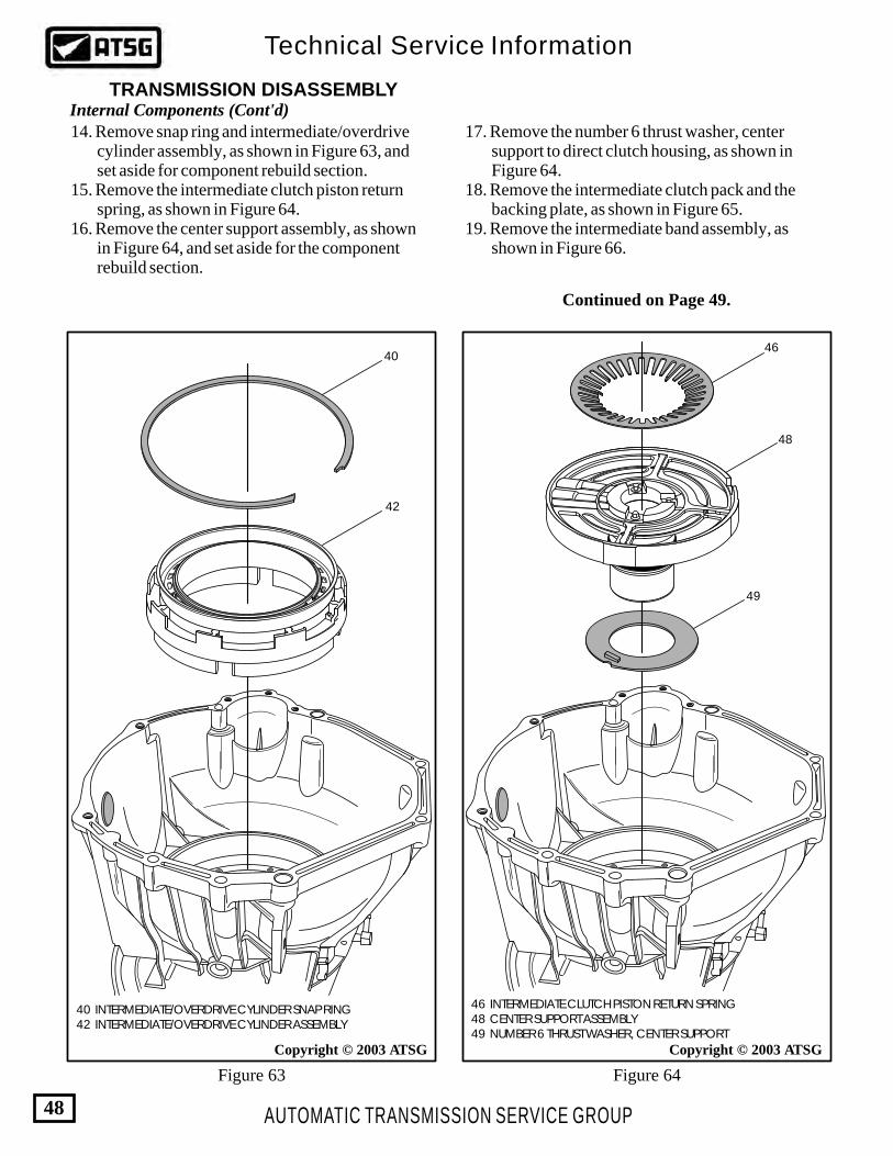
14. Remove snap ring and intermediate/overdrive cylinder assembly, as shown in Figure 63, and set aside for component rebuild section. 15. Remove the intermediate clutch piston return spring, as shown in Figure 64. 16. Remove the center support assembly, as shown in Figure 64, and set aside for the component rebuild section.
17. Remove the number 6 thrust washer, center support to direct clutch housing, as shown in Figure 64. 18. Remove the intermediate clutch pack and the backing plate, as shown in Figure 65. 19. Remove the intermediate band assembly, as shown in Figure 66.
40
42
Figure 63
Copyright © 2003 ATSG
40 INTERMEDIATE/OVERDRIVE CYLINDER SNAP RING 42 INTERMEDIATE/OVERDRIVE CYLINDER ASSEMBLY
46 INTERMEDIATE CLUTCH PISTON RETURN SPRING 48 CENTER SUPPORT ASSEMBLY 49 NUMBER 6 THRUST WASHER, CENTER SUPPORT

AUTOMATIC TRANSMISSION SERVICE GROUP
Technical Service Information
49
Figure 65
Continued on Page 50.
Copyright © 2003 ATSG Copyright © 2003 ATSG
INTERMEDIATEBAND ASSEMBLY
DIRECT CLUTCH,FORWARD CLUTCH
AND SUN SHELLASSEMBLY
REMOVAL TOOLT89T-70010-E
TRANSMISSION DISASSEMBLYInternal Components (Cont'd)
Figure 66
52 INTERMEDIATE CLUTCH FRICTION PLATES 53 INTERMEDIATE CLUTCH STEEL PLATES 54 INTERMEDIATE CLUTCH BACKING PLATE
54
52
53
20. Install the removal tool and remove the direct clutch drum, forward clutch drum and the sun shell as an assembly, as shown in Figure 66. 21. Set the direct drum, forward drum and the sun shell assembly aside for the component rebuild section.

AUTOMATIC TRANSMISSION SERVICE GROUP
Technical Service Information
50
Copyright © 2003 ATSG
Figure 69
Figure 68
106
107
112
TRANSMISSION DISASSEMBLYInternal Components (Cont'd)
Continued on Page 51.
102OUTPUT SHAFT
SNAP RING
103
105
104
Figure 67
Copyright © 2003 ATSG
102 REAR CARRIER TO REVERSE HUB RETAINING SNAP RING 103 NUMBER 10B THRUST WASHER 104 REAR PLANETARY CARRIER ASSEMBLY
106 OUTPUT SHAFT SNAP RING 107 REAR PLANETARY RING GEAR 112 NUMBER 12 THRUST BEARING (RING GEAR TO INNER RACE)
22. Remove the snap ring retaining rear planetary carrier in reverse clutch hub (See Figure 67). 23. Remove the rear planetary carrier and both of the thrust washers, as shown in Figure 67. 24. Remove the output shaft snap ring using snap ring pliers, as shown in Figure 68. 25. Remove snap ring, rear planetary ring gear and the number 12 thrust bearing (See Figure 69).

26. Remove the reverse clutch hub and low roller clutch assembly, as shown in Figure 70, and set aside for component rebuild. 27. Remove the snap ring retaining the low/reverse clutch pack, using a large screwdriver as shown in Figure 71, from the groove in case. 28. Remove the snap ring from case, as shown in Figure 72.
AUTOMATIC TRANSMISSION SERVICE GROUP
Technical Service Information
51
Figure 70
Continued on Page 52.
Copyright © 2003 ATSG Copyright © 2003 ATSG
SNAPRING
LOW REVERSE CLUTCHSNAP RING
TRANSMISSION DISASSEMBLYInternal Components (Cont'd)
Figure 72
Figure 71
110 REVERSE CLUTCH HUB AND LOW ROLLER CLUTCH ASM.
110

AUTOMATIC TRANSMISSION SERVICE GROUP
Technical Service Information
52
Figure 74
TRANSMISSION DISASSEMBLYInternal Components (Cont'd)
Continued on Page 53.
98
99
101
100
Figure 73
Copyright © 2003 ATSG
98 LOW/REVERSE CLUTCH BACKING PLATE 99 LOW/REVERSE CLUTCH FRICTION PLATES (6) 100 LOW/REVERSE CLUTCH STEEL PLATES (6)
29. Remove the low/reverse clutch pack including wave plate, as shown in Figure 73. 30. Rotate transmission in fixture so output shaft is facing up, as shown in Figure 74. 31. Remove the extension housing retaining bolts and housing, as shown in Figure 74. 32. We have illustrated the typical 4WD version in Figure 74, and the 2WD version in Figure 75.
EXTENSION HOUSINGRETAINING BOLTS
EXTENSIONHOUSING
EXTENSIONHOUSING GASKET
OUTPUTSHAFT
9.8
9.8
9.8
9.8
9.89.8
9.8
9.8
5GBD
-8H17
BD-8H
17
PRB-AU
PRB-AU
0000
0066
0000
0066
0000
0066
0000
0066
9594
9594
XC3P-
GAXC
3P-GA
MP-4
X 4
MP-4
X 4
9.8
9.8
Copyright © 2003 ATSG

AUTOMATIC TRANSMISSION SERVICE GROUP
Technical Service Information
53
Figure 75
Continued on Page 54.
RETAININGBOLTS
PARK PAWL,PIVOT PIN,
AND RETURNSPRING
PARK RODGUIDE PLATE
TRANSMISSION DISASSEMBLYInternal Components (Cont'd)
Figure 76
5GBD
-8H17
BD-8H
17
PRB-AU
PRB-AU
0000
0066
0000
0066
0000
0066
0000
0066
9594
9594
XC3P-
GAXC
3P-GA
MP-4
X 4
MP-4
X 4
9.8
9.8
Copyright © 2003 ATSG
33. Notice that the 2WD version has a speed sensor reluctor wheel that must be pressed off and on, if necessary to replace, as shown in Figure 75. 34. Remove and discard the extension housing gasket, as shown in Figure 74. 35. Remove the park rod guide plate, parking pawl, park pawl pivot pin and return spring, as shown in Figure 76.
OUTPUTSHAFT
SPEED SENSORRELUCTOR WHEEL
5GBD
-8H17
BD-8H
17
PRB-AU
PRB-AU
0000
0066
0000
0066
0000
0066
0000
0066
9594
9594
XC3P-
GAXC
3P-GA
MP-4
X 4
MP-4
X 4
9.8
9.8
Copyright © 2003 ATSG
SPACER, ROTUNDAPART NUMBER 307-388

AUTOMATIC TRANSMISSION SERVICE GROUP
Technical Service Information
54
Figure 79
Figure 78
TRANSMISSION DISASSEMBLYInternal Components (Cont'd)
Continued on Page 55.
Figure 77
36. Remove the output shaft by pulling straight up, as shown in Figure 77. 37. Remove the number 13 thrust bearing from the back of case, as shown in Figure 77. 38. Remove and discard the lube orifice plug from rear of case, as shown in Figure 78.
LOW ROLLER CLUTCH INNERRACE RETAINING BOLTS (5)
LUBE ORIFICEPLUG
OUTPUT SHAFTAND PARK GEAR
NUMBER 13THRUST BEARING
5GBD
-8H17
BD-8H
17
PRB-AU
PRB-AU
0000
0066
0000
0066
0000
0066
0000
0066
9594
9594
XC3P-
GAXC
3P-GA
MP-4
X 4
MP-4
X 4
9.8
9.8
9.8
9.89.8
Copyright © 2003 ATSG
Copyright © 2003 ATSG
5GBD-8H17BD-8H17
PRB-AUPRB-AU0000006600000066
000000660000006695949594
XC3P-GAXC3P-GA
MP-4 X 4MP-4 X 4
9.8
9.8
9.8
9.8
9.8
Copyright © 2003 ATSG

113 LOW ROLLER CLUTCH INNER RACE 114 REVERSE CLUTCH PISTON RETURN SPRING ASSEMBLY 115 REVERSE CLUTCH PISTON INNER LIP SEAL 116 REVERSE CLUTCH PISTON OUTER LIP SEAL 117 REVERSE CLUTCH PISTON
AUTOMATIC TRANSMISSION SERVICE GROUP
Technical Service Information
55
Figure 80
INSIDEDETENTLEVER
RETAININGNUT
TRANSMISSION DISASSEMBLY
COMPONENT REBUILD
Internal Components (Cont'd)
Transmission Case Assembly
Figure 81
Copyright © 2003 ATSG Copyright © 2003 ATSG
113
114
117
115
116
39. Rotate the transmission in fixture so the pan rail surface is facing down (See Figure 79). 40. Remove the 5 low roller clutch inner race bolts, as shown in Figure 79. 41. Rotate the transmission in fixture so the bell housing is facing up, as shown in Figure 80. 42. Remove the low roller clutch inner race, the reverse clutch piston return spring assembly, and reverse clutch piston (See Figure 80). 43. Remove and discard the reverse clutch piston inner and outer lip seals (See Figure 80).
1. Remove the inside detent lever retaining nut, using a cresent wrench to hold the external shift lever, to avoid damage to the inside detent spring (See Figure 80). Caution: If this procedure is not followed, damage to the detent spring will occur and replacement will be necessary.
6262
Hold External Shift Lever With CresentWrench When Removing The
Inside Detent Lever Retaining Nut
Continued on Page 56.

7. Install the external shift lever, inside detent lever and retaining nut. Torque the retaining nut to 41-54 N·m (30-40 ft.lb.), again using a cresent wrench to hold external shift lever. (See Figure 81). 8. Install a new lube orifice plug into the case, as shown in Figure 83, and ensure fully seated. 9. Install new inner and outer lip seals in grooves of the reverse piston, with the lips facing the direction shown in Figure 85. 10. Lubricate both lip seals with a small amount of Trans-Jel®. 11. Install the reverse piston into the case with a rotating motion, using care not to damage the lip seals (See Figure 85). 12. Install the reverse clutch piston return spring assembly, as shown in Figure 85. 13. Install two threaded rods into the low roller inner race, as shown in Figure 84. They can be made from bolts with the head removed. Note: The lube hole in the race should be positioned in the 5 o'clock position when it is installed. The 6 o'clock position is the bottom of the case. 14. Install the low roller clutch inner race in case, as shown in Figure 86, and install two nuts on the threaded rods.
AUTOMATIC TRANSMISSION SERVICE GROUP
Technical Service Information
56
Figure 84
Figure 82
Continued on Page 57.
Figure 83
2. Remove the shift lever retaining roll pin from the case, using pin removal tool T87P-3504-N, as shown in Figure 82. 3. Remove external shift lever from case and remove shift lever seal from case using the proper puller. 4. Clean all case parts thoroughly and dry with compressed air. 5. Inspect all case parts thoroughly for any wear and/or damage. Replace as necessary. 6. Install new shift lever seal into the case bore using the proper seal driver
LOW ROLLER CLUTCHINNER RACE
TWO THREADED RODS5/16"-24 X 3 INCH LONG
LUBE HOLE
LUBE ORIFICEPLUG
PIN REMOVERT87P-3504-N
ROLLPIN
Copyright © 2003 ATSG Copyright © 2003 ATSG
COMPONENT REBUILDTransmission Case Assembly (Cont'd)

5GBD
-8H17
BD-8H
17
PRB-AU
PRB-AU
0000
0066
0000
0066
0000
0066
0000
0066
9594
9594
XC3P-
GAXC
3P-GA
MP-4
X 4
MP-4
X 4
9.8
9.8
9.8
9.89.8
Snap-On
5GBD-8H17BD-8H17
PRB-AUPRB-AU0000006600000066
000000660000006695949594
XC3P-GAXC3P-GA
MP-4 X 4MP-4 X 4
9.8
9.8
9.8
113 LOW ROLLER CLUTCH INNER RACE 114 REVERSE CLUTCH PISTON RETURN SPRING ASSEMBLY 115 REVERSE CLUTCH PISTON INNER LIP SEAL 116 REVERSE CLUTCH PISTON OUTER LIP SEAL 117 REVERSE CLUTCH PISTON
AUTOMATIC TRANSMISSION SERVICE GROUP
Technical Service Information
57
Figure 85
Figure 86
Figure 87
Copyright © 2003 ATSG
113
114
117
115
116
15. Tighten the nuts to compress the reverse clutch return spring assembly, as shown in Figure 86. 16. Install 3 low roller inner race retaining bolts, as shown in Figure 86, and remove the 2 threaded rods and nuts. 17. Install the two remaining retaining bolts and torque all five to 24-34 N·m (18-25 ft.lb.) in a criss-cross pattern, as shown in Figure 87.
COMPONENT REBUILDTransmission Case Assembly (Cont'd)
INSTALL THREELOW ROLLER CLUTCH INNER
RACE RETAINING BOLTS
TWO THREADED RODS
Copyright © 2003 ATSG
Copyright © 2003 ATSG
Continued on Page 58.
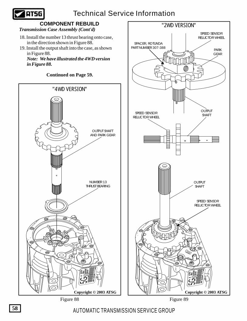
AUTOMATIC TRANSMISSION SERVICE GROUP
Technical Service Information
58
Figure 89Figure 88
OUTPUT SHAFTAND PARK GEAR
NUMBER 13THRUST BEARING
5GBD
-8H17
BD-8H
17
PRB-AU
PRB-AU
0000
0066
0000
0066
0000
0066
0000
0066
9594
9594
XC3P-
GAXC
3P-GA
MP-4
X 4
MP-4
X 4
9.8
9.8
9.8
9.89.8
Copyright © 2003 ATSG
18. Install the number 13 thrust bearing onto case, in the direction shown in Figure 88. 19. Install the output shaft into the case, as shown in Figure 88. Note: We have illustrated the 4WD version in Figure 88.
COMPONENT REBUILDTransmission Case Assembly (Cont'd)
Continued on Page 59.
Copyright © 2003 ATSG
OUTPUTSHAFT
SPEED SENSORRELUCTOR WHEEL
PARKGEAR
SPEED SENSORRELUCTOR WHEEL
SPACER, ROTUNDAPART NUMBER 307-388
5GBD
-8H17
BD-8H
17
PRB-AU
PRB-AU
0000
0066
0000
0066
0000
0066
0000
0066
9594
9594
XC3P-
GAXC
3P-GA
MP-4
X 4
MP-4
X 4
9.8
9.8
OUTPUTSHAFT
SPEED SENSORRELUCTOR WHEEL
"2WD VERSION"
"4WD VERSION"
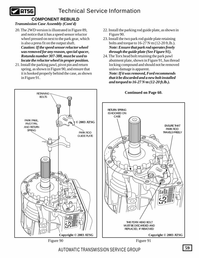
AUTOMATIC TRANSMISSION SERVICE GROUP
Technical Service Information
59
Figure 90 Figure 91
Copyright © 2003 ATSG
RETAININGBOLTS
PARK PAWL,PIVOT PIN,
AND RETURNSPRING
PARK RODGUIDE PLATE
5GBD
-8H17
BD-8H
17
PRB-AU
PRB-AU
0000
0066
0000
0066
0000
0066
0000
0066
9594
9594
XC3P-
GAXC
3P-GA
MP-4
X 4
MP-4
X 4
9.8
9.8
Copyright © 2003 ATSG Copyright © 2003 ATSG
20. The 2WD version is illustrated in Figure 89, and notice that it has a speed sensor reluctor wheel pressed on next to the park gear, which is also a press fit on the output shaft. Caution: If the speed sensor reluctor wheel was removed for any reason, special spacer, Rotunda number 307-388, must be used to locate the reluctor wheel in proper position. 21. Install the parking pawl, pivot pin and return spring, as shown in Figure 90, and ensure that it is hooked properly behind the case, as shown in Figure 91.
22. Install the parking rod guide plate, as shown in Figure 90. 23. Install the two park rod guide plate retaining bolts and torque to 16-27 N·m (12-20 ft.lb.). Note: Ensure that park rod operates freely through the guide plate (See Figure 91). 24. The Torx head bolt retaining the park pawl abutment plate, shown in Figure 91, has thread locking compound and should not be removed unless damage is apparent. Note: If it was removed, Ford recommends that it be discarded and a new bolt installed and torqued to 16-27 N·m (12-20 ft.lb.).
COMPONENT REBUILDTransmission Case Assembly (Cont'd)
Continued on Page 60.
RETURN SPRINGIS HOOKED ON
CASE
RETURN SPRINGIS HOOKED ON
CASE
ENSURE THATPARK ROD
TRAVELS FREELY
ENSURE THATPARK ROD
TRAVELS FREELY
THIS TORX HEAD BOLTMUST BE DISCARDED ANDREPLACED, IF REMOVED
THIS TORX HEAD BOLTMUST BE DISCARDED ANDREPLACED, IF REMOVED
5GBD
-8H17
BD-8H
17
PRB-AU
PRB-AU
0000
0066
0000
0066
0000
0066
0000
0066
9594
9594
XC3P-
GAXC
3P-GA
MP-4
X 4
MP-4
X 4
9.8
9.8
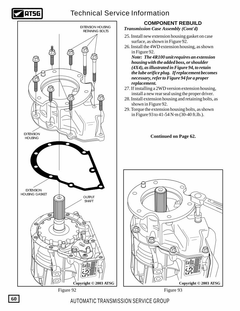
AUTOMATIC TRANSMISSION SERVICE GROUP
Technical Service Information
60
5GBD
-8H17
BD-8H
17
PRB-AU
PRB-AU
0000
0066
0000
0066
0000
0066
0000
0066
9594
9594
XC3P-
GAXC
3P-GA
MP-4
X 4
MP-4
X 4
9.89.8
9.89.8
9.8
9.8
9.8 9.8
9.8
Copyright © 2003 ATSG
EXTENSION HOUSINGRETAINING BOLTS
EXTENSIONHOUSING
EXTENSIONHOUSING GASKET
OUTPUTSHAFT
9.8
9.8
9.8
9.8
9.89.8
9.8
9.8
5GBD
-8H17
BD-8H
17
PRB-AU
PRB-AU
0000
0066
0000
0066
0000
0066
0000
0066
9594
9594
XC3P-
GAXC
3P-GA
MP-4
X 4
MP-4
X 4
9.8
9.8
Copyright © 2003 ATSG
Figure 92 Figure 93
25. Install new extension housing gasket on case surface, as shown in Figure 92. 26. Install the 4WD extension housing, as shown in Figure 92. Note: The 4R100 unit requires an extension housing with the added boss, or shoulder (4X4), as illustrated in Figure 94, to retain the lube orifice plug. If replacement becomes necessary, refer to Figure 94 for a proper replacement. 27. If installing a 2WD version extension housing, install a new rear seal using the proper driver. 28. Install extension housing and retaining bolts, as shown in Figure 92. 29. Torque the extension housing bolts, as shown in Figure 93 to 41-54 N·m (30-40 ft.lb.).
COMPONENT REBUILDTransmission Case Assembly (Cont'd)
Continued on Page 62.

AUTOMATIC TRANSMISSION SERVICE GROUP
Technical Service Information
61
Copyright © 2003 ATSG
FORD 4R1006.8L AND 7.3L
2 WHEEL DRIVE
SHOULDER
SHOULDERADDED BOSS
4R100 TYPICAL4 WHEEL DRIVE
ALL OTHER 4R1002 WHEEL DRIVEAPPLICATIONS
E4OD WITHOUTLUBE PLUG
NO SHOULDER
NO SHOULDER
E4OD 4X4 WITHOUTLUBE PLUG
Figure 94

AUTOMATIC TRANSMISSION SERVICE GROUP
Technical Service Information
62
Figure 97Figure 96
Figure 95
LOW ROLLERCLUTCH ASM.
REVERSE HUBASSEMBLY
Copyright © 2003 ATSG
30. Install the low roller clutch into the reverse hub in the direction shown in Figure 96, and rotate slightly clock-wise to lock it in place. Caution: If the roller clutch is installed in reverse hub in the direction shown in Figure 95, the reverse hub will freewheel in both directions, when installed in case. 31. Rotate the transmission in fixture so the bell housing is facing up, as shown in Figure 97. 32. Install the reverse hub and low roller clutch assembly into the case by rotating clockwise, as shown in Figure 97, until fully seated. Note: Reverse clutch hub should freewheel clockwise and lock counter-clockwise after installation in case. 33. Install the reverse clutch "Wave" plate on top of the reverse piston in the case, as shown in Figure 98. 34. Install the reverse clutch pack beginning with a steel plate and alternating with a friction plate as shown in Figure 98, until the proper amount of plates are installed.
COMPONENT REBUILDTransmission Case Assembly (Cont'd)
Continued on Page 63.
Copyright © 2003 ATSG
110 REVERSE CLUTCH HUB AND LOW ROLLER CLUTCH ASM.
110
IF THE ROLLER CLUTCH IS INSTALLED INTHIS DIRECTION, THE REVERSE HUB WILL
FREEWHEEL IN BOTH DIRECTIONS,WHEN INSTALLED IN CASE.
INSTALL IN THIS DIRECTION ANDTURN SLIGHTLY CLOCK-WISE TO
LOCK IN PLACE
"INCORRECT" INSTALLATION
"CORRECT" INSTALLATION

99 100
AUTOMATIC TRANSMISSION SERVICE GROUP
Technical Service Information
63
Figure 98 Figure 99
98
97
101
Copyright © 2003 ATSG
97 LOW/REVERSE CLUTCH BACKING PLATE SNAP RING 98 LOW/REVERSE CLUTCH BACKING PLATE 99 LOW/REVERSE CLUTCH FRICTION PLATES (6) 100 LOW/REVERSE CLUTCH STEEL PLATES (6) 101 LOW/REVERSE CLUTCH "WAVE" PLATE
35. Install the reverse clutch backing plate on top of the last friction, as shown in Figure 98. 36. Install the reverse clutch backing plate snap ring, as shown in Figure 98, and ensure that it is fully seated in case groove. Note: The number of reverse plates is model sensitive and may vary from the illustration. A stack-up clearance measurement is not required for the reverse clutch. 37. Install the number 12 thrust bearing and rear ring gear into case, as shown in Figure 99. Note: Before installing snap ring provisions must be made to retain output shaft fully seated against rear bearing. 38. Install the output shaft snap ring onto output shaft, as shown in Figure 99 Note: Do not over stretch snap ring during installation. Ford recommends a new snap ring for this location. 39. Ensure that snap ring is fully seated in groove in output shaft, and the case is finally ready for the final assembly process.
Transmission Case Assembly (Cont'd)
Copyright © 2003 ATSG
106
107
112
106 OUTPUT SHAFT SNAP RING 107 REAR PLANETARY RING GEAR 112 NUMBER 12 THRUST BEARING (RING GEAR TO INNER RACE)

AUTOMATIC TRANSMISSION SERVICE GROUP
Technical Service Information
64
Figure 100
Figure 101
6 PINION REARPLANETARY CARRIER
F81Z-7D006-AA
4 PINION REARPLANETARY CARRIER
REQUIRES 4 TANGTHRUST WASHERS
BOTH SIDES
REQUIRES 4 TANGTHRUST WASHERS
BOTH SIDES
REQUIRES 3 TANGTHRUST WASHERF0TZ-7A166-D
REQUIRES 3 TANGTHRUST WASHERF0TZ-7A166-D
Copyright © 2003 ATSG
Copyright © 2003 ATSG
1. Inspect planetary carriers for the following; Carrier pins for loosness or damage. Pinion gears for damaged or worn teeth. Pinion gears for free rotation, and wobble. Carrier for cracks, wear and/or damage. 2. Use a new service part if any of the above conditions exist. 3. Set the carriers aside for final assembly.
Both planetary carriers are model sensitive parts, and may contain a 4 pinion carrier or a 6 pinion carrier, as shown in Figures 100, 101. Obviously the 6 pinion carrier has much more torque carrying capacity and is highly recommended, especially in heavy duty applications. The 6 pinion rear carrier also requires 3 tang thrust washers on both sides of the carrier. We have provided you with the part numbers, in Figure 100, that were current at the time of printing this manual.
COMPONENT REBUILDFront And Rear Planetary Carriers
Planetary Carrier Differences
6 PINION REAR CARRIER4 PINION REAR CARRIER
6 PINION FORWARDPLANETARY CARRIER
F81Z-7A398-CA4 PINION FORWARDPLANETARY CARRIER
6 PINION REAR CARRIER4 PINION REAR CARRIER
Continued on Page 66.

FORWARD CLUTCH EXPLODED VIEW
84 83 82 80 79
78 77 75 74
73
72
76
81
Figure 102
72 FORWARD CLUTCH HOUSING 73 FORWARD CLUTCH HOUSING INNER "O" RING SEAL 74 FORWARD PISTON OUTER LIP SEAL 75 FORWARD CLUTCH PISTON ASSEMBLY 76 FORWARD CLUTCH PISTON APPLY RING 77 FORWARD CLUTCH PISTON "BELLVILLE" RETURN SPRING 78 FORWARD CLUTCH RETURN SPRING SNAP RING 79 FORWARD CLUTCH APPLY PLATE 80 FORWARD CLUTCH "WAVE" PLATE 81 FORWARD CLUTCH FRICTION PLATES 82 FORWARD CLUTCH STEEL PLATES 83 FORWARD CLUTCH BACKING PLATE 84 FORWARD CLUTCH BACKING PLATE SNAP RING (SELECTIVE)
AUTOMATIC TRANSMISSION SERVICE GROUP
Technical Service Information
65
Copyright © 2003 ATSG

AUTOMATIC TRANSMISSION SERVICE GROUP
Technical Service Information
66
Copyright © 2003 ATSG
70 FORWARD CLUTCH SEALING RINGS (2 REQUIRED) 72 FORWARD CLUTCH HOUSING ASSEMBLY
72
70
1. Disassemble the forward clutch housing using Figure 102 as a guide. 2. Clean all forward clutch housing parts using a suitable cleaning solution and dry with compressed air. 3. Inspect all forward clutch housing parts for any wear and/or damage. Note: Ensure that the air bleed ball in the forward clutch piston is free and operational (See Figure 104). 4. Remove and discard the forward clutch inner and outer seals. 5. Place the forward clutch housing on a flat work surface, in the direction shown in Figure 103, and install new sealing rings.
COMPONENT REBUILDForward Clutch Housing
72 FORWARD CLUTCH HOUSING 73 FORWARD CLUTCH HOUSING INNER "O" RING SEAL 74 FORWARD PISTON OUTER LIP SEAL 75 FORWARD CLUTCH PISTON ASSEMBLY
Copyright © 2003 ATSG
72
73
74
75
76
ENSURE THATBALL IS FREE
AND SEALS
Figure 103 Figure 104
Continued on Page 67.
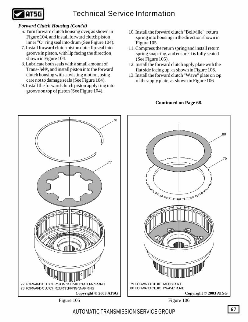
AUTOMATIC TRANSMISSION SERVICE GROUP
Technical Service Information
67
77 FORWARD CLUTCH PISTON "BELLVILLE" RETURN SPRING 78 FORWARD CLUTCH RETURN SPRING SNAP RING
Copyright © 2003 ATSG
78
77
6. Turn forward clutch housing over, as shown in Figure 104, and install forward clutch piston inner "O" ring seal into drum (See Figure 104). 7. Install forward clutch piston outer lip seal into groove in piston, with lip facing the direction shown in Figure 104. 8. Lubricate both seals with a small amount of Trans-Jel®, and install piston into the forward clutch housing with a twisting motion, using care not to damage seals (See Figure 104). 9. Install the forward clutch piston apply ring into groove on top of piston (See Figure 104).
Forward Clutch Housing (Cont'd)
Continued on Page 68.
79 FORWARD CLUTCH APPLY PLATE 80 FORWARD CLUTCH "WAVE" PLATE
80
79
Copyright © 2003 ATSG
Figure 105 Figure 106
10. Install the forward clutch "Bellville" return spring into housing in the direction shown in Figure 105. 11. Compress the return spring and install return spring snap ring, and ensure it is fully seated (See Figure 105). 12. Install the forward clutch apply plate with the flat side facing up, as shown in Figure 106. 13. Install the forward clutch "Wave" plate on top of the apply plate, as shown in Figure 106.

AUTOMATIC TRANSMISSION SERVICE GROUP
Technical Service Information
68
81
82
83
84
81 FORWARD CLUTCH FRICTION PLATES 82 FORWARD CLUTCH STEEL PLATES 83 FORWARD CLUTCH BACKING PLATE 84 FORWARD CLUTCH BACKING PLATE SNAP RING (SELECTIVE)
"SELECTIVE"SNAP RING
Copyright © 2003 ATSG
Selective Snap Rings Available1.42-1.52mm (.056" - .060")1.88-1.98mm (.074" - .078")2.34-2.44mm (.092" - .096")2.79-2.90mm (.110" - .114")3.25-3.35mm (.128" - .132")
Forward Clutch Clearance Should Be0.76 - 1.40mm (.030" - .055")
Copyright © 2003 ATSG
14. Install forward clutch pack beginning with a steel plate and alternating with a friction plate, as shown in Figure 107, until the proper amount of plates are installed. Note: The number of forward plates is model sensitive and may vary from the illustration. 15. Install the forward clutch backing plate, as shown in Figure 107. 16. Install selective forward clutch backing plate snap ring, as shown in Figure 107, and ensure that it is fully seated. 17. Measure the forward clutch clearance between the selective snap ring and the backing plate, as shown in Figure 108. 18. Forward clutch clearance should measure: 0.76 - 1.40mm (.030" - .055"). 19. Change the selective snap ring as necessary to obtain the proper clearance (See Figure 108). 20. Set the completed forward clutch housing aside for future sub assembly.
Forward Clutch Housing (Cont'd)
Figure 107 Figure 108

AUTOMATIC TRANSMISSION SERVICE GROUP
Technical Service Information
69
5958
Copyright © 2003 ATSG
57 INTERMEDIATE SPRAG ASSEMBLY 58 INTERMEDIATE SPRAG OUTER RACE THRUST WASHER (NUMBER 7) 59 DIRECT CLUTCH HOUSING ASSEMBLY
57
DIRECT CLUTCH HOUSING "FRONT SIDE" EXPLODED VIEW
"DIODE" ONE-WAYCLUTCH ASSEMBLY
DIRECT DRUM FOR"DIODE" ONE-WAYCLUTCH ASSEMBLY
"DO NOT USE" REPLACE WITH PARTS SHOWN ABOVE
"DO NOT USE" REPLACE WITH PARTS SHOWN ABOVE
Figure 109

AUTOMATIC TRANSMISSION SERVICE GROUP
Technical Service Information
70
Copyright © 2003 ATSG
59 DIRECT CLUTCH HOUSING ASSEMBLY 60 DIRECT CLUTCH PISTON INNER LIP SEAL 61 DIRECT CLUTCH PISTON OUTER LIP SEAL 62 DIRECT CLUTCH PISTON ASSEMBLY 63 DIRECT CLUTCH PISTON RETURN SPRING ASSEMBLY 64 DIRECT CLUTCH PISTON RETURN SPRING SNAP RING 66 DIRECT CLUTCH FRICTION PLATES 67 DIRECT CLUTCH STEEL PLATES 68 DIRECT CLUTCH BACKING PLATE 69 DIRECT CLUTCH BACKING PLATE SNAP RING (SELECTIVE)
F
9T
P-7
A2
62
-CA
L-2
0F
ord
Ford
59
60
6162
DIRECT CLUTCH HOUSING "REAR SIDE" EXPLODED VIEW
6364
69 68 67
66"SELECTIVE"SNAP RING
Figure 110
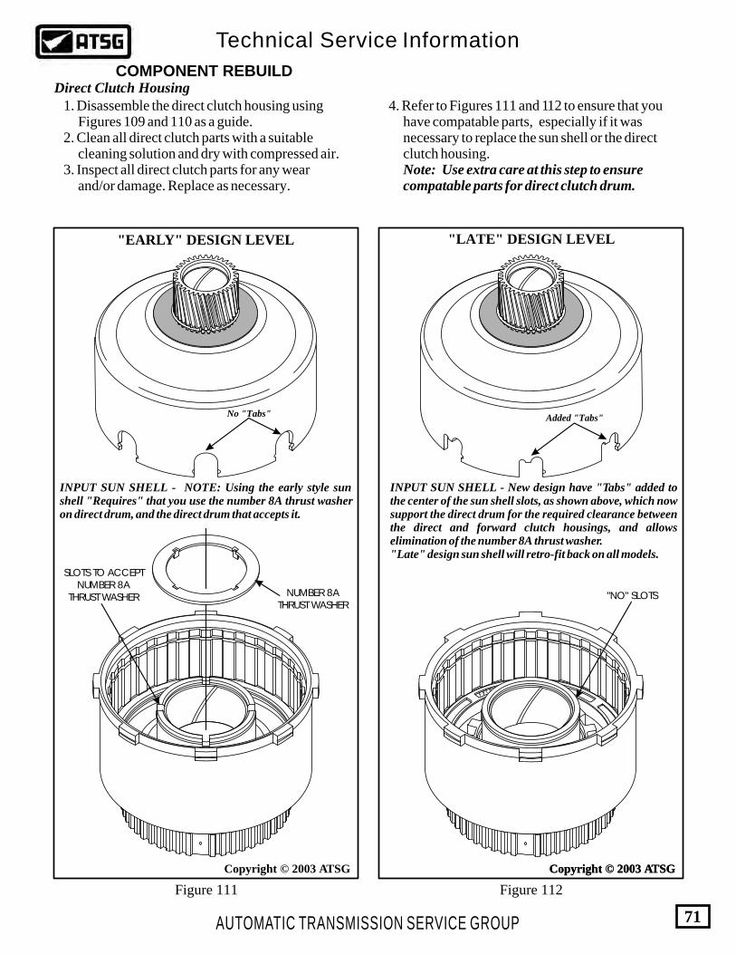
AUTOMATIC TRANSMISSION SERVICE GROUP
Technical Service Information
71
Copyright © 2003 ATSG
F 9 T P - 7 A 2 6 2 - C A
L-20Ford Ford
Copyright © 2003 ATSGCopyright © 2003 ATSG
NUMBER 8ATHRUST WASHER
SLOTS TO ACCEPTNUMBER 8A
THRUST WASHER "NO" SLOTS
INPUT SUN SHELL - New design have "Tabs" added to the center of the sun shell slots, as shown above, which now support the direct drum for the required clearance between the direct and forward clutch housings, and allows elimination of the number 8A thrust washer."Late" design sun shell will retro-fit back on all models.
INPUT SUN SHELL - NOTE: Using the early style sun shell "Requires" that you use the number 8A thrust washer on direct drum, and the direct drum that accepts it.
Figure 111 Figure 112
"EARLY" DESIGN LEVEL "LATE" DESIGN LEVEL
Added "Tabs"No "Tabs"
COMPONENT REBUILDDirect Clutch Housing 1. Disassemble the direct clutch housing using Figures 109 and 110 as a guide. 2. Clean all direct clutch parts with a suitable cleaning solution and dry with compressed air. 3. Inspect all direct clutch parts for any wear and/or damage. Replace as necessary.
4. Refer to Figures 111 and 112 to ensure that you have compatable parts, especially if it was necessary to replace the sun shell or the direct clutch housing. Note: Use extra care at this step to ensure compatable parts for direct clutch drum.

AUTOMATIC TRANSMISSION SERVICE GROUP
Technical Service Information
72
Copyright © 2003 ATSG
Copyright © 2003 ATSG
58 INTERMEDIATE SPRAG OUTER RACE THRUST WASHER (NO. 7) 59 DIRECT CLUTCH HOUSING ASSEMBLY
59
58
"DIODE" STYLEONE-WAY CLUTCH
DIRECT DRUM FOR"DIODE" STYLE
ONE-WAY CLUTCH
Copyright © 2003 ATSG
57 INTERMEDIATE SPRAG ASSEMBLY 58 INTERMEDIATE SPRAG OUTER RACE THRUST WASHER (NO. 7) 59 DIRECT CLUTCH HOUSING ASSEMBLY
58
57
59
COMPONENT REBUILDDirect Clutch Housing (Cont'd) 5. We have illustrated the "Diode" style one-way intermediate clutch and the associated direct clutch drum in Figure 113. Note: Do Not use this type of one-way clutch in this unit. It will not live. 6. Place the direct clutch housing on a flat work surface in the direction shown in Figure 114. 7. Install the number 7 thrust washer, as shown in Figure 114, and retain with Trans-Jel®.
DO NOT USE THIS STYLE DRUM
Figure 113
Figure 114 Figure 115

AUTOMATIC TRANSMISSION SERVICE GROUP
Technical Service Information
73
Copyright © 2003 ATSG Copyright © 2003 ATSG
FR LEEE EWH
HOLD DIRECTCLUTCH DRUM
FREEWHEEL OUTERSPRAG RACE
59 DIRECT CLUTCH HOUSING ASSEMBLY 60 DIRECT CLUTCH PISTON INNER LIP SEAL 61 DIRECT CLUTCH PISTON OUTER LIP SEAL
F 9 T P - 7 A 2 6 2 - C A
L-20Ford Ford
59
60
61
62
COMPONENT REBUILDDirect Clutch Housing (Cont'd) 8. Install the intermediate sprag assembly and the outer sprag race, as shown in Figure 115. 9. After installing intermediate sprag assembly, check to ensure proper operation, as shown in Figure 116. Note: Outer sprag race should freewheel counter-clockwise and lock clockwise, as shown in Figure 116. 10. Turn the direct clutch housing over on a flat work surface, as shown in Figure 117. 11. Install the inner direct clutch piston lip seal in the groove in drum, with the lip facing in the direction shown in Figure 117. 12. Install the outer direct clutch piston lip seal in the groove in drum, with the lip facing in the direction shown in Figure 117. 13. Lubricate both seals and both piston surfaces with a small amount of Trans-Jel®. 14. Install the direct clutch piston assembly into direct clutch housing with a twisting motion, using care so as not to damage the lip seals. (See Figure 117).
Figure 116 Figure 117
Continued on Page 74.

F 9 T P - 7 A 2 6 2 - C A
L-20Ford Ford
AUTOMATIC TRANSMISSION SERVICE GROUP
Technical Service Information
74
Copyright © 2003 ATSG
59
63
64
Copyright © 2003 ATSG
65
59 DIRECT CLUTCH HOUSING ASSEMBLY 63 DIRECT CLUTCH PISTON RETURN SPRING ASSEMBLY 64 DIRECT CLUTCH PISTON RETURN SPRING SNAP RING 65 NUMBER 8A THRUST WASHER (NOT USED ALL MODELS)
Figure 118 Figure 119
COMPONENT REBUILDDirect Clutch Housing (Cont'd) 15. Install the direct clutch piston return spring into direct clutch housing, as shown in Figure 118. 16. Compress the return spring assembly using a foot press and install the direct clutch return spring snap ring (See Figure 118). 17. Install the number 8A thrust washer at this time if your unit requires one because of the early style sun shell (See Figure 119) Note: Refer to Figures 111 and 112 for the information regarding the 8A thrust washer, and compatable parts.
18. Install the direct clutch pack beginning with a steel plate and alternating with a friction plate, as shown in Figure 120, until you have proper amount of plates installed. Note: The number of direct plates is model sensitive and may vary from illustration. 19. Install the direct clutch backing plate on top of the last friction plate, as shown in Figure 120. 20. Install the selective direct clutch backing plate snap ring, as shown in Figure 120, and ensure that it is fully seated. 21. Measure the direct clutch clearance between the selective snap ring and the backing plate, as shown in Figure 121. 22. Direct clutch clearance should measure: 1.15 - 2.06mm (.045" - .081"). 23. Change the selective snap ring as necessary to obtain the proper clutch clearance. Refer to Figure 121 for snap rings available. 24. Set the completed direct clutch housing aside for future sub-assembly.

F 9 T P - 7 A 2 6 2 - C A
L-20Ford Ford
AUTOMATIC TRANSMISSION SERVICE GROUP
Technical Service Information
75
Copyright © 2003 ATSG
66 DIRECT CLUTCH FRICTION PLATES 67 DIRECT CLUTCH STEEL PLATES 68 DIRECT CLUTCH BACKING PLATE
67
66
69
68
"SELECTIVE"SNAP RING
Figure 120
F 9 T P - 7 A 2 6 2 - C A
L-20Ford Ford
Direct Clutch Clearance Should Be1.15 - 2.06mm (.045" - .081")
Selective Snap Rings Available1.65-1.75mm (.065" - .069")1.88-1.98mm (.074" - .078")2.10-2.20mm (.083" - .087")
Copyright © 2003 ATSG
Figure 121

F 9 T P - 7 A 2 6 2 - C A
L-20Ford Ford
59 "LATE" DIRECT CLUTCH HOUSING ASSEMBLY 72 FORWARD CLUTCH HOUSING ASSEMBLY
59 "EARLY" DIRECT CLUTCH HOUSING ASSEMBLY
59
72
59
AUTOMATIC TRANSMISSION SERVICE GROUP
Technical Service Information
76
Copyright © 2003 ATSGCopyright © 2003 ATSG
NUMBER 8ATHRUST WASHER
Some ModelsOnly
Does Not UseNumber 8A
Thrust WasherAnd RequiresLate Sun Shell
COMPONENT REBUILDForward And Direct Clutch Sub-Assemblies 1. We are once again showing you the difference between the "Early" and "Late" direct clutch housings in Figures 122 and 123, as this is the last chance you will have to install the number 8A thrust washer, if you require one. 2. Place the completed direct clutch housing on a flat work surface in the direction that is shown in Figure 123. 3. Install the completed forward clutch housing into the completed direct clutch housing by rotating back and forth until fully seated, as shown in Figure 123.
4. Install the number 9A thrust bearing into the forward clutch housing in the direction shown in Figure 124, with black side facing up. 5. Install the number 8C thrust washer onto the forward ring gear and hub assembly, as shown in Figure 125, and retain with Trans-Jel®. 6. Install forward ring gear and thrust washer into forward clutch plates, as shown in Figure 126, by rotating back and forth until fully seated.
Figure 122 Figure 123
Continued on Page 78.

F 9 T P - 7 A 2 6 2 - C A
L-20Ford Ford
59 DIRECT CLUTCH HOUSING ASSEMBLY 72 FORWARD CLUTCH HOUSING ASSEMBLY 88 FORWARD RING GEAR AND HUB ASSEMBLY
88
FORWARD RINGGEAR AND HUB
ASSEMBLY
NUMBER 8CTHRUST WASHER
72
59
AUTOMATIC TRANSMISSION SERVICE GROUP
Technical Service Information
77
Copyright © 2003 ATSG
Copyright © 2003 ATSG
F 9 T P - 7 A 2 6 2 - C A
L-20Ford Ford
59 DIRECT CLUTCH HOUSING ASSEMBLY 72 FORWARD CLUTCH HOUSING ASSEMBLY 89 NUMBER 9A THRUST BEARING ASSEMBLY
89
72
59
Copyright © 2003 ATSG
Figure 124 Figure 126
Figure 125

NUMBER 10ATHRUST BEARING
FORWARDPLANETARY
NUMBER 9BTHRUST BEARING
FORWARDPLANETARY
AUTOMATIC TRANSMISSION SERVICE GROUP
Technical Service Information
78
Copyright © 2003 ATSG
Copyright © 2003 ATSG
F 9 T P - 7 A 2 6 2 - C A
L-20Ford Ford
59 DIRECT CLUTCH HOUSING ASSEMBLY 72 FORWARD CLUTCH HOUSING ASSEMBLY 91 "6 PINION" FORWARD PLANETARY CARRIER ASSEMBLY
91
72
59
Copyright © 2003 ATSG
COMPONENT REBUILD
7. Install the number 10A thrust bearing onto the forward planetary carrier, in the direction that is shown in Figure 127, and retain the bearing with Trans-Jel®. 8. Turn the planetary carrier over and install the number 9B thrust bearing into the planetary carrier in the direction shown in Figure 128. Note: Black side faces up. 9. Install the complete forward planetary carrier assembly into the ring gear, by rotating into position, as shown in Figure 129.
Figure 127
Figure 128 Figure 129
Continued on Page 79.
Forward And Direct Clutch Sub-Assemblies

AUTOMATIC TRANSMISSION SERVICE GROUP
Technical Service Information
79
Copyright © 2003 ATSG
F 9 T P - 7 A 2 6 2 - C A
L-20Ford Ford
59 DIRECT CLUTCH HOUSING ASSEMBLY 72 FORWARD CLUTCH HOUSING ASSEMBLY 94 "LATE" SUN GEAR AND SHELL ASSEMBLY
94
NUMBER 8BTHRUST BEARING
72
59
Copyright © 2003 ATSG
COMPLETED FORWARD/DIRECT ASSEMBLY
Figure 130 Figure 131
COMPONENT REBUILD
10. Install the proper sun gear shell over the entire assembly, as shown in Figure 130. 11. Hold the completed assembly together and roll complete assembly over so that it is setting on the sun gear, as shown in Figure 131. 12. Install the number 8B thrust washer onto the forward clutch drum surface, in the direction shown in Figure 131.
13. Install the installation tool onto the complete assembly, as shown in Figure 131, and set the completed assembly aside for final assembly.
Forward And Direct Clutch Sub-Assemblies

CENTER SUPPORT EXPLODED VIEW
49
CENTER SUPPORT HUB
CENTERSUPPORT
HUB
CENTERSUPPORT
CENTERSUPPORT
RETAININGBOLTS (3)
RETAININGBOLTS (3)
CENTERSUPPORT
BALL BEARING
CENTERSUPPORT
BALL BEARING
50
48
48 CENTER SUPPORT ASM. (SERVICED AS ASSEMBLY) 49 CENTER SUPPORT DIRECT CLUTCH SEALING RINGS (2) 50 NUMBER 6 THRUST WASHER
AUTOMATIC TRANSMISSION SERVICE GROUP
Technical Service Information
80
Copyright © 2003 ATSG
BALL BEARING(KOYO 6906)
Copyright © 2003 ATSG
COMPONENT REBUILDCenter Support Assembly 1. Disassemble center support, if necessary, using Figure 132 as a guide. 2. Clean all center support parts thoroughly using a suitable cleaning solution and blow dry with compressed air. 3. Inspect all center support parts thoroughly for any wear and/or damage. 4. Remove and discard the two center support direct clutch sealing rings (See Figure 132). 5. It is not necessary to remove the center support from the hub, but if you did, assemble the hub to support as shown in Figure 133, and torque the retaining bolts to 9 -14 N·m (80-100 in.lb.). 6. The ball bearing in the center support is not serviced by Ford, but is available from your local bearing supply house using the number supplied in Figure 133. 7. Install a new ball bearing into center support, as shown in Figure 133, using proper bearing drivers. 8. Turn the center support over and install new sealing rings into the grooves in center support hub, as shown in Figure 134.
Continued on Page 81.
Figure 132
Figure 133

AUTOMATIC TRANSMISSION SERVICE GROUP
Technical Service Information
81
COMPLETED CENTER SUPPORT ASSEMBLY
Copyright © 2003 ATSG
48
49
50
48 CENTER SUPPORT ASM. (SERVICED AS ASSEMBLY) 49 CENTER SUPPORT DIRECT CLUTCH SEALING RINGS (2) 50 NUMBER 6 THRUST WASHER
Copyright © 2003 ATSG
Figure 135
Figure 134
COMPONENT REBUILDCenter Support Assembly 9. If the sealing rings are the "Hook" joint type, ensure that they are properly hooked and that they rotate freely in the grooves. 10. Install the number 6 thrust washer onto center support, as shown in Figure 134, and retain with Trans-Jel®. 11. Set the completed center support assembly aside for final assembly (See Figure 135).
Component RebuildContinued on Page 82.
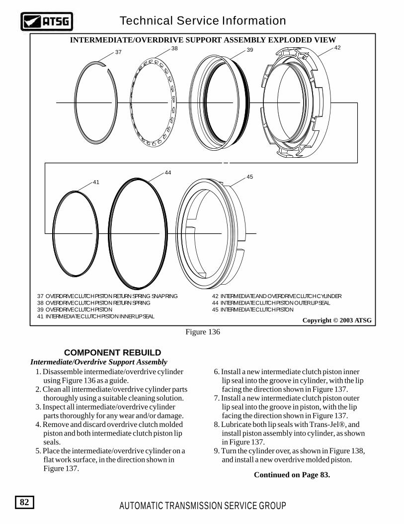
AUTOMATIC TRANSMISSION SERVICE GROUP
Technical Service Information
82
Copyright © 2003 ATSG
37 OVERDRIVE CLUTCH PISTON RETURN SPRING SNAP RING 38 OVERDRIVE CLUTCH PISTON RETURN SPRING 39 OVERDRIVE CLUTCH PISTON 41 INTERMEDIATE CLUTCH PISTON INNER LIP SEAL
42 INTERMEDIATE AND OVERDRIVE CLUTCH CYLINDER 44 INTERMEDIATE CLUTCH PISTON OUTER LIP SEAL 45 INTERMEDIATE CLUTCH PISTON
COMPONENT REBUILDIntermediate/Overdrive Support Assembly
INTERMEDIATE/OVERDRIVE SUPPORT ASSEMBLY EXPLODED VIEW
3738 39 42
41
4445
1. Disassemble intermediate/overdrive cylinder using Figure 136 as a guide. 2. Clean all intermediate/overdrive cylinder parts thoroughly using a suitable cleaning solution. 3. Inspect all intermediate/overdrive cylinder parts thoroughly for any wear and/or damage. 4. Remove and discard overdrive clutch molded piston and both intermediate clutch piston lip seals. 5. Place the intermediate/overdrive cylinder on a flat work surface, in the direction shown in Figure 137.
6. Install a new intermediate clutch piston inner lip seal into the groove in cylinder, with the lip facing the direction shown in Figure 137. 7. Install a new intermediate clutch piston outer lip seal into the groove in piston, with the lip facing the direction shown in Figure 137. 8. Lubricate both lip seals with Trans-Jel®, and install piston assembly into cylinder, as shown in Figure 137. 9. Turn the cylinder over, as shown in Figure 138, and install a new overdrive molded piston.
Figure 136
Continued on Page 83.
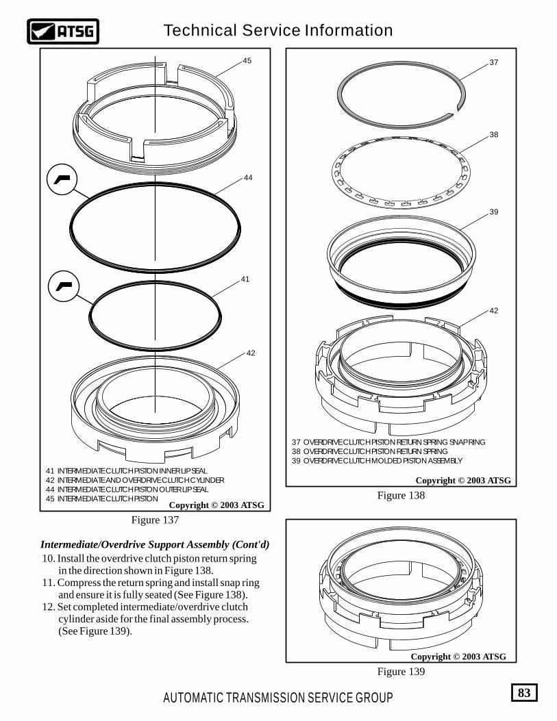
41 INTERMEDIATE CLUTCH PISTON INNER LIP SEAL 42 INTERMEDIATE AND OVERDRIVE CLUTCH CYLINDER 44 INTERMEDIATE CLUTCH PISTON OUTER LIP SEAL 45 INTERMEDIATE CLUTCH PISTON
AUTOMATIC TRANSMISSION SERVICE GROUP
Technical Service Information
83
Copyright © 2003 ATSG
Copyright © 2003 ATSG
Copyright © 2003 ATSG
37 OVERDRIVE CLUTCH PISTON RETURN SPRING SNAP RING 38 OVERDRIVE CLUTCH PISTON RETURN SPRING 39 OVERDRIVE CLUTCH MOLDED PISTON ASSEMBLY
45
44
41
42
42
39
38
37
Figure 137
Figure 138
Figure 139
10. Install the overdrive clutch piston return spring in the direction shown in Figure 138. 11. Compress the return spring and install snap ring and ensure it is fully seated (See Figure 138). 12. Set completed intermediate/overdrive clutch cylinder aside for the final assembly process. (See Figure 139).
Intermediate/Overdrive Support Assembly (Cont'd)

Copyright © 2003 ATSG
3230
28
27
2624 25 29
33
24 OVERDRIVE ROLLER OUTER RACE "FLAT" SNAP RING 25 OVERDRIVE ROLLER OUTER RACE 26 NUMBER 3 THRUST WASHER, OUTER RACE TO CARRIER 27 OVERDRIVE PLANETARY CARRIER ASSEMBLY 28 NUMBER 6 THRUST BEARING, CARRIER TO CENTER SHAFT 29 OVERDRIVE INTERNAL RING GEAR 30 CENTER SHAFT ASSEMBLY 32 CENTER SHAFT TO RING GEAR "WAVE" SNAP RING 33 NUMBER 5 THRUST BEARING, CENTER SHAFT TO SUPPORT
OVERDRIVE GEARSET EXPLODED VIEW
Figure 140
AUTOMATIC TRANSMISSION SERVICE GROUP
Technical Service Information
84
COMPONENT REBUILDOverdrive Gearset Assembly 1. Disassemble overdrive gearset using Figure 140 as a guide. 2. Clean all overdrive gearset parts thoroughly using a suitable cleaning solution. 3. Inspect all overdrive gearset parts thoroughly for any wear and/or damage.
4. Position the overdrive ring gear on a flat work surface, as shown in Figure 141. 5. Install overdrive roller clutch outer race into overdrive ring gear, as shown in Figure 141. Note: Groove in outer race must face up, as shown in Figure 141.

26 NUMBER 3 THRUST WASHER, OUTER RACE TO CARRIER 27 OVERDRIVE PLANETARY CARRIER ASSEMBLY
Copyright © 2003 ATSG
Copyright © 2003 ATSG
29
GROOVEFACING UP 25
24
24 OVERDRIVE ROLLER OUTER RACE "FLAT" SNAP RING 25 OVERDRIVE ROLLER OUTER RACE 29 OVERDRIVE INTERNAL RING GEAR
Copyright © 2003 ATSG
27
26
Ensure that snap ring is fully seated.
Figure 143
Figure 142
Figure 141
AUTOMATIC TRANSMISSION SERVICE GROUP
Technical Service Information
85
Overdrive Gearset Assembly (Cont'd) 6. Install the flat snap ring into the groove in ring gear, as shown in Figure 141, and ensure that it is fully seated, as shown in Figure 142. 7. Install number 3 thrust washer onto back of the overdrive planetary carrier and retain with a small amount of Trans-Jel® (See Figure 143).
Continued on Page 86.
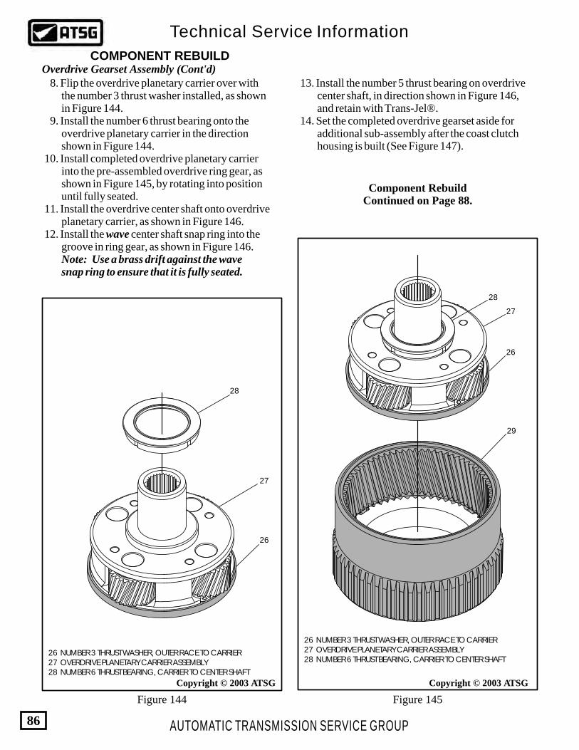
Figure 145Figure 144
Copyright © 2003 ATSG Copyright © 2003 ATSG
26 NUMBER 3 THRUST WASHER, OUTER RACE TO CARRIER 27 OVERDRIVE PLANETARY CARRIER ASSEMBLY 28 NUMBER 6 THRUST BEARING, CARRIER TO CENTER SHAFT
28
27
26
28
27
26
29
26 NUMBER 3 THRUST WASHER, OUTER RACE TO CARRIER 27 OVERDRIVE PLANETARY CARRIER ASSEMBLY 28 NUMBER 6 THRUST BEARING, CARRIER TO CENTER SHAFT
AUTOMATIC TRANSMISSION SERVICE GROUP
Technical Service Information
86
COMPONENT REBUILDOverdrive Gearset Assembly (Cont'd) 8. Flip the overdrive planetary carrier over with the number 3 thrust washer installed, as shown in Figure 144. 9. Install the number 6 thrust bearing onto the overdrive planetary carrier in the direction shown in Figure 144. 10. Install completed overdrive planetary carrier into the pre-assembled overdrive ring gear, as shown in Figure 145, by rotating into position until fully seated. 11. Install the overdrive center shaft onto overdrive planetary carrier, as shown in Figure 146. 12. Install the wave center shaft snap ring into the groove in ring gear, as shown in Figure 146. Note: Use a brass drift against the wave snap ring to ensure that it is fully seated.
13. Install the number 5 thrust bearing on overdrive center shaft, in direction shown in Figure 146, and retain with Trans-Jel®. 14. Set the completed overdrive gearset aside for additional sub-assembly after the coast clutch housing is built (See Figure 147).
Component RebuildContinued on Page 88.
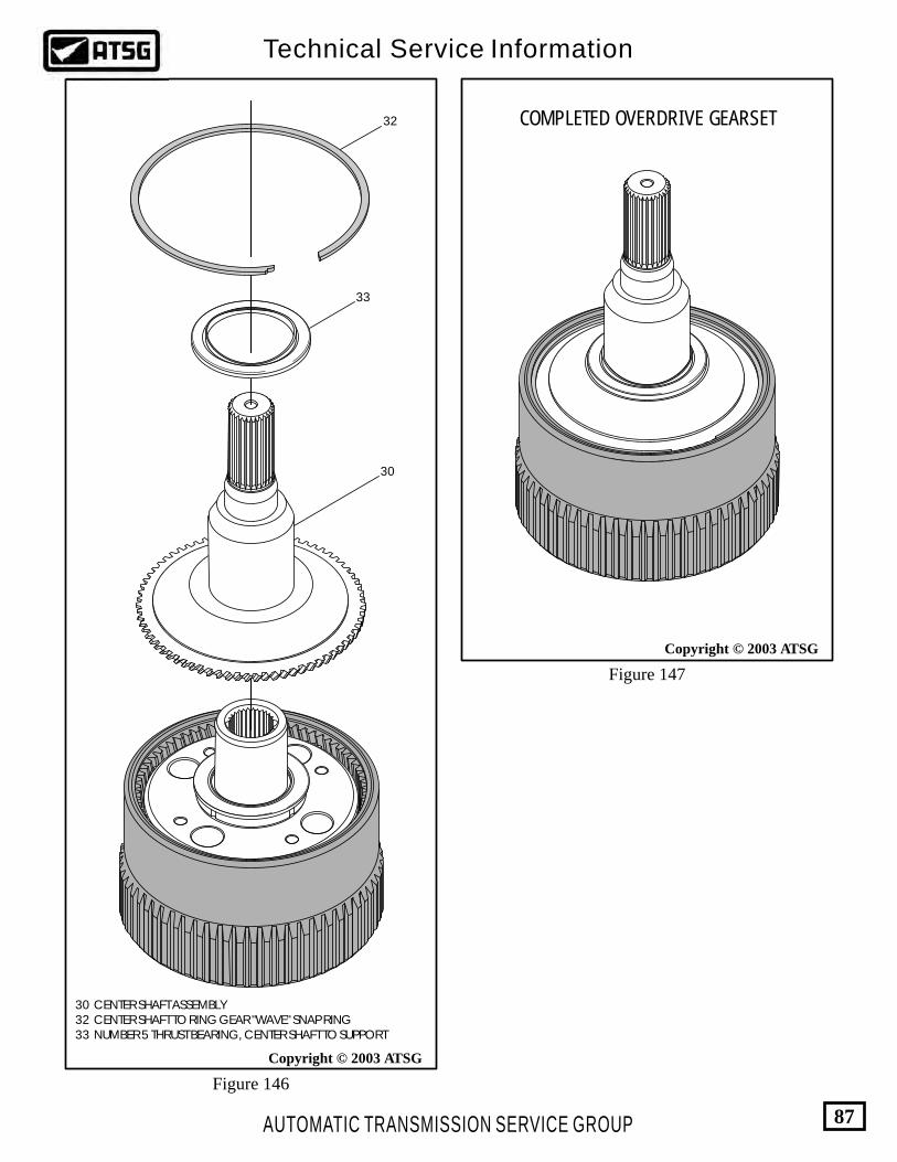
Copyright © 2003 ATSG
Copyright © 2003 ATSG
30 CENTER SHAFT ASSEMBLY 32 CENTER SHAFT TO RING GEAR "WAVE" SNAP RING 33 NUMBER 5 THRUST BEARING, CENTER SHAFT TO SUPPORT
Figure 147
Figure 146
32
33
30
COMPLETED OVERDRIVE GEARSET
AUTOMATIC TRANSMISSION SERVICE GROUP
Technical Service Information
87
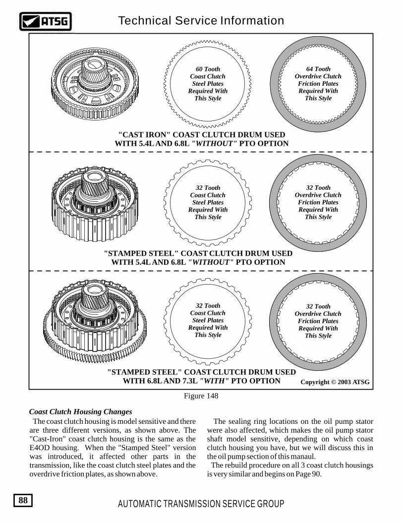
60 ToothCoast ClutchSteel Plates
Required WithThis Style
32 ToothCoast ClutchSteel Plates
Required WithThis Style
32 ToothCoast ClutchSteel Plates
Required WithThis Style
"CAST IRON" COAST CLUTCH DRUM USEDWITH 5.4L AND 6.8L "WITHOUT" PTO OPTION
"STAMPED STEEL" COAST CLUTCH DRUM USEDWITH 5.4L AND 6.8L "WITHOUT" PTO OPTION
"STAMPED STEEL" COAST CLUTCH DRUM USEDWITH 6.8L AND 7.3L "WITH" PTO OPTION
64 ToothOverdrive ClutchFriction PlatesRequired With
This Style
32 ToothOverdrive ClutchFriction PlatesRequired With
This Style
32 ToothOverdrive ClutchFriction PlatesRequired With
This Style
Figure 148
Coast Clutch Housing Changes The coast clutch housing is model sensitive and there are three different versions, as shown above. The "Cast-Iron" coast clutch housing is the same as the E4OD housing. When the "Stamped Steel" version was introduced, it affected other parts in the transmission, like the coast clutch steel plates and the overdrive friction plates, as shown above.
The sealing ring locations on the oil pump stator were also affected, which makes the oil pump stator shaft model sensitive, depending on which coast clutch housing you have, but we will discuss this in the oil pump section of this manaul. The rebuild procedure on all 3 coast clutch housings is very similar and begins on Page 90.
AUTOMATIC TRANSMISSION SERVICE GROUP
Technical Service Information
88
Copyright © 2003 ATSG
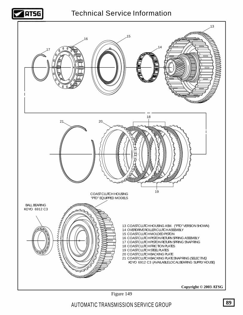
AUTOMATIC TRANSMISSION SERVICE GROUP
Technical Service Information
89
Copyright © 2003 ATSG
13
14
1516
17
18
19
2021
COAST CLUTCH HOUSING"PTO" EQUIPPED MODELS
BALL BEARINGKOYO 6912 C3
Figure 149
13 COAST CLUTCH HOUSING ASM. ("PTO" VERSION SHOWN) 14 OVERDRIVE ROLLER CLUTCH ASSEMBLY 15 COAST CLUTCH MOLDED PISTON 16 COAST CLUTCH PISTON RETURN SPRING ASSEMBLY 17 COAST CLUTCH PISTON RETURN SPRING SNAP RING 18 COAST CLUTCH FRICTION PLATES 19 COAST CLUTCH STEEL PLATES 20 COAST CLUTCH BACKING PLATE 21 COAST CLUTCH BACKING PLATE SNAP RING (SELECTIVE) KOYO 6912 C3 (AVAILABLE LOCAL BEARING SUPPLY HOUSE)

Coast Clutch Housing 1. Disassemble the coast clutch housing using Figures 148 and 149 as a guide. Note: Figure 148 illustrates the 3 different coast clutch housings available in 4R100 transmissions. The procedures for rebuild are very similar. We will be illustrating the "PTO" version. 2. Clean all coast clutch housing parts thoroughly using a suitable cleaning solution and dry with compressed air. 3. Inspect all coast clutch parts thoroughly for any wear and/or damage. 4. Remove and discard the molded coast clutch piston. (See Figure 149). 5. Replace the ball bearing as necessary using the proper pullers and press (See Figure 150). Note: This ball bearing is not available from Ford individualy, but is available from your local bearing supply under KOYO 6912 C3. 6. Place the coast clutch housing on a flat work surface, as shown in Figure 151.
AUTOMATIC TRANSMISSION SERVICE GROUP
Technical Service Information
90
Copyright © 2003 ATSGCopyright © 2003 ATSG
Copyright © 2003 ATSG
COAST CLUTCH HOUSING"PTO" EQUIPPED MODELS
BALL BEARINGKOYO 6912 C3
COMPONENT REBUILD
Figure 150
Figure 151 Figure 152
KOYO 6912 C3 (AVAILABLE LOCAL BEARING SUPPLY HOUSE)
16 COAST CLUTCH PISTON RETURN SPRING ASSEMBLY 17 COAST CLUTCH PISTON RETURN SPRING SNAP RING
13 COAST CLUTCH HOUSING ASM. ("PTO" VERSION SHOWN) 15 COAST CLUTCH MOLDED PISTON
15
13
SEALPROTECTOR
307-387
16
17
Continued on Page 91.

18
19
20
21
AUTOMATIC TRANSMISSION SERVICE GROUP
Technical Service Information
91
Copyright © 2003 ATSG
Figure 153 Figure 154
Copyright © 2003 ATSG
13 COAST CLUTCH HOUSING ASM. ("PTO" VERSION SHOWN) 14 OVERDRIVE ROLLER CLUTCH ASSEMBLY
13 COAST CLUTCH HOUSING ASM. ("PTO" VERSION SHOWN) 18 COAST CLUTCH FRICTION PLATES 19 COAST CLUTCH STEEL PLATES 20 COAST CLUTCH BACKING PLATE 21 COAST CLUTCH BACKING PLATE SNAP RING (SELECTIVE)
14
13
Coast Clutch Housing (Cont'd) 7. Install lip seal protector 307-387 onto the coast clutch housing, as shown in Figure 151. 8. Lubricate both seals on the new coast clutch piston and install piston into the coast clutch housing, as shown in Figure 151. 9. Install the coast clutch piston return spring assembly, as shown in Figure 152. 10. Compress the return spring assembly using a foot press and install the return spring snap ring, as shown in Figure 152, and ensure that it is fully seated. 11. Install the overdrive roller clutch assembly, as shown in Figure 153, and rotate roller clutch counter-clockwise to lock it in position. 12. Install the coast clutch plates in coast clutch housing, as shown in Figure 154, beginning with a steel plate and alternating with friction plates, until you have proper amount installed. Note: The number of coast plates is model sensitive and may vary from illustration. 13. Install the coast clutch backing plate, as shown in Figure 154.
Continued on Page 92.

AUTOMATIC TRANSMISSION SERVICE GROUP
Technical Service Information
92
Copyright © 2003 ATSG Copyright © 2003 ATSG
Figure 155 Figure 156
Coast Clutch Clearance Should Be0.76 - 1.27mm (.030" - .050")
Selective Snap Rings Available1.35 - 1.45mm (.053" - .057")1.75 - 1.85mm (.068" - .072")2.15 - 2.25mm (.084" - .088")
COMPLETEDOVERDRIVE GEARSET
ASSEMBLY
COAST CLUTCHASSEMBLY WITH
CLUTCHES REMOVED
Coast Clutch Housing (Cont'd) Coast Clutch Housing (Cont'd)
14. Install the selective coast clutch backing plate snap ring, as shown in Figure 154, and ensure that it is fully seated. 15. Measure the coast clutch clearance between the selective snap ring and backing plate, as shown in Figure 155. Coast clutch clearance should be 0.76 - 1.27mm (.030" - .050"). 16. Change the selective snap ring as necessary to obtain proper clutch clearance. Refer to Figure 155 for snap ring thickness' available. 17. After you have obtained the proper clearance, remove all of the coast clutch plates. 18. With coast clutch plates removed, install the pre-assembled overdrive gearset onto coast clutch housing, as shown in Figure 156, by rotating counter-clockwise until fully seated. Note: After installation, overdrive gearset should freewheel counter-clockwise and lock in a clockwise direction, while holding the coast clutch housing.
19. Re-install the coast clutch plates, as shown in Figure 157. 20. Install the coast clutch remover/installer, as shown in Figure 158. Special Note: This tool is almost mandatory for the "PTO" version. The overdrive clutches must be installed "before" the coast clutch housing is installed, as they will not pass by the PTO gear. 21. If you are rebuilding the "Non-PTO" version, the input shaft can be used, with transmission centerline horizontal, to install this assembly and then install the overdrive clutches. We do not have that luxury with the "PTO" version, please use the installation tool. Caution: The overdrive one-way clutch may be damaged if the tool is not used or installed correctly. The tool must tightly hold entire assembly. 22. Set the completed assembly aside for the final assembly process (See Figure 158).
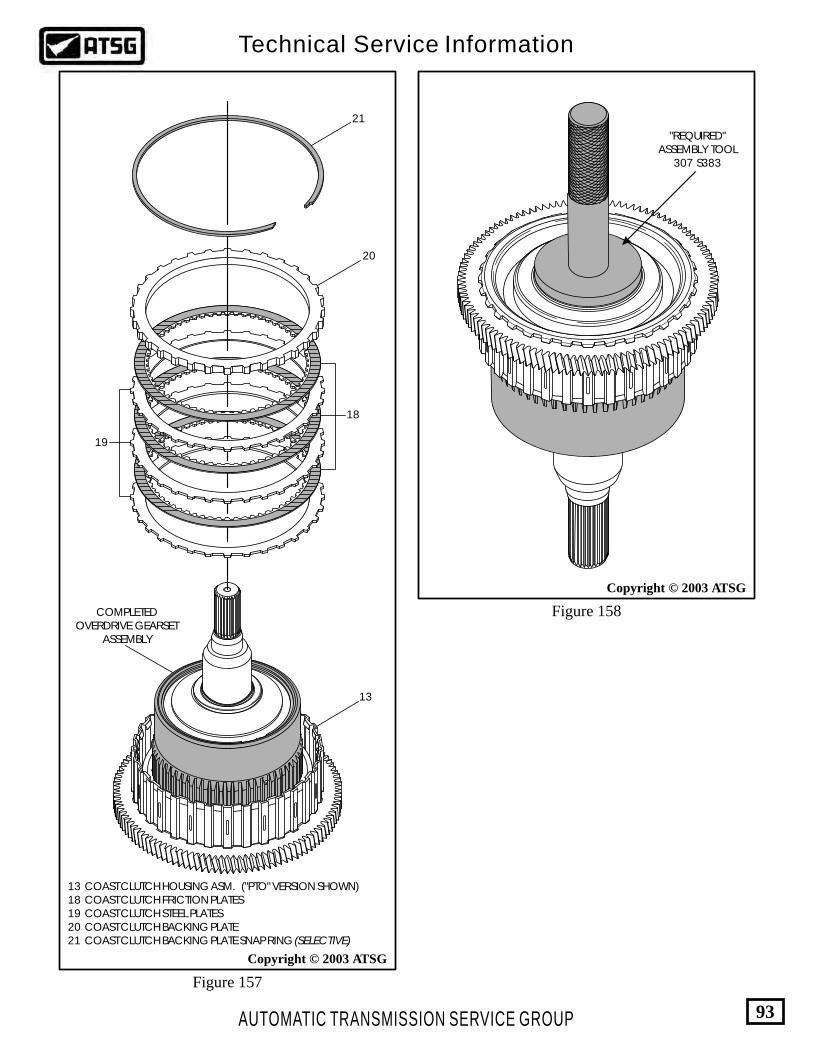
AUTOMATIC TRANSMISSION SERVICE GROUP
Technical Service Information
93
Copyright © 2003 ATSG
"REQUIRED"ASSEMBLY TOOL
307 S383
Copyright © 2003 ATSG
18
19
20
21
13 COAST CLUTCH HOUSING ASM. ("PTO" VERSION SHOWN) 18 COAST CLUTCH FRICTION PLATES 19 COAST CLUTCH STEEL PLATES 20 COAST CLUTCH BACKING PLATE 21 COAST CLUTCH BACKING PLATE SNAP RING (SELECTIVE)
Figure 158
Figure 157
13
COMPLETEDOVERDRIVE GEARSET
ASSEMBLY

RF-F8
1P
7A
10
5-A
A
Ford
Ford
Ford
RF
-F
81
P-7
B3
24
-A
A 107
98
KX
V9
.8
KX
V9.8
KX
V9.8
KX
V9
.8
KX
V9
.8
KX
V9
.8
KX
V9
.8
KX
V9
.8
KX
V9
.8
KX
V9
.8
KX
V9
.8
KX
V9.8
OIL PUMP ASSEMBLY "FRONT" SIDE EXPLODED VIEW
OIL PUMP ASSEMBLY "REAR" SIDE EXPLODED VIEW
12
3 4
56
7
8
10 11
13
12
9
1 OIL PUMP CONVERTER SEAL 2 OIL PUMP CONVERTER HUB BUSHING 3 OIL PUMP BODY 4 OIL PUMP BODY TO CASE "O" RING SEAL 5 OIL PUMP INNER GEAR 6 OIL PUMP OUTER GEAR 7 STATOR SHAFT CONVERTER SEAL RING 8 STATOR SHAFT AND OIL PUMP COVER ASSEMBLY 9 COAST CLUTCH SEAL RINGS (2 REQUIRED) 10 STATOR SHAFT TO OIL PUMP COVER RETAINING BOLTS (3 REQUIRED) 11 STATOR SHAFT ASSEMBLY 12 OIL PUMP COVER ASSEMBLY 13 OIL PUMP COVER TO OIL PUMP BODY RETAINING BOLTS (12 REQUIRED)
AUTOMATIC TRANSMISSION SERVICE GROUP
Technical Service Information
94
Copyright © 2003 ATSG
Figure 159
Refer to Page 34 through 37 forspecific Oil Pump Differences
between "PWM" and "NON-PWM"
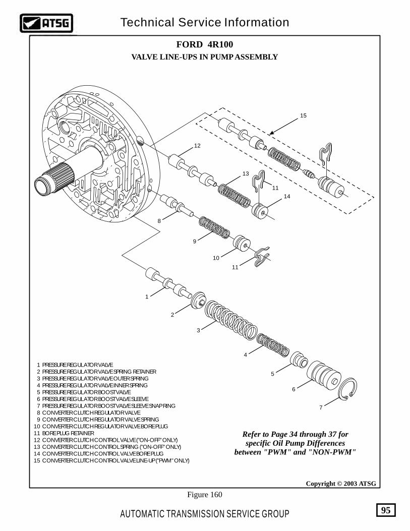
FORD 4R100
VALVE LINE-UPS IN PUMP ASSEMBLY
1
2
3
4
5
6
7
8
9
10
11
12
13
14
11
15
AUTOMATIC TRANSMISSION SERVICE GROUP
Technical Service Information
95
Copyright © 2003 ATSG
1 PRESSURE REGULATOR VALVE 2 PRESSURE REGULATOR VALVE SPRING RETAINER 3 PRESSURE REGULATOR VALVE OUTER SPRING 4 PRESSURE REGULATOR VALVE INNER SPRING 5 PRESSURE REGULATOR BOOST VALVE 6 PRESSURE REGULATOR BOOST VALVE SLEEVE 7 PRESSURE REGULATOR BOOST VALVE SLEEVE SNAP RING 8 CONVERTER CLUTCH REGULATOR VALVE 9 CONVERTER CLUTCH REGULATOR VALVE SPRING 10 CONVERTER CLUTCH REGULATOR VALVE BORE PLUG 11 BORE PLUG RETAINER 12 CONVERTER CLUTCH CONTROL VALVE ("ON-OFF" ONLY) 13 CONVERTER CLUTCH CONTROL SPRING ("ON-OFF" ONLY) 14 CONVERTER CLUTCH CONTROL VALVE BORE PLUG 15 CONVERTER CLUTCH CONTROL VALVE LINE-UP ("PWM" ONLY)
Figure 160
Refer to Page 34 through 37 forspecific Oil Pump Differences
between "PWM" and "NON-PWM"

RF-F81P7A105-AA
Ford
AUTOMATIC TRANSMISSION SERVICE GROUP
Technical Service Information
96
Copyright © 2003 ATSGCopyright © 2003 ATSG
Copyright © 2003 ATSG
Oil Pump Body And Cover Assembly 1. Disassemble the oil pump and cover assembly using Figure 159 as a guide. 2. Clean all of the oil pump and cover parts using a suitable cleaning solution. 3. Inspect all oil pump and cover parts for any wear and/or damage. Note: Refer to Pages 34 through 37 for the differences between PWM and NON-PWM, if any parts replacement is necessary. 4. Remove and discard oil pump converter seal, oil pump body to case seal ring, and the two coast clutch seal rings (See Figure 159). 5. Install new converter bushing into the oil pump body, as shown in Figure 161, using the proper drivers for removal and installation. 6. Install new converter hub seal into the oil pump body, as shown in Figure 161, using the proper drivers for removal and installation. 7. Turn the oil pump body over and install inner and outer pump gears, as shown in Figure 162, and lubricate with transmission fluid. 8. Set the completed pump body aside for the future sub-assembly (See Figure 163). 9. Install the valves, springs and bore plugs into the oil pump cover assembly exactly as shown in Figure 160. Note: Refer to Pages 34 through 37 for the specific differences between PWM and the NON-PWM pump covers. 10. It is not necessary to remove the stator shaft assembly from the pump cover unless damage is apparent (See Figure 164).
COMPONENT REBUILDOIL PUMP BODY
CONVERTER SEAL
OIL PUMP BODYCONVERTER
BUSHING
OIL PUMP BODY
I.D. DOT MUSTFACE UP
I.D. DOT MUSTFACE UP
OIL PUMPINNER GEAR
OIL PUMPOUTER GEAR
OIL PUMPBODY
Figure 161
Figure 162 Figure 163
COMPLETED OIL PUMP BODY ASSEMBLY
Continued on Page 97.
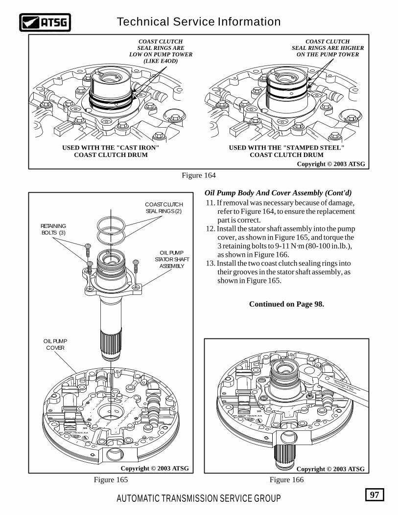
AUTOMATIC TRANSMISSION SERVICE GROUP
Technical Service Information
97
Copyright © 2003 ATSG
COAST CLUTCHSEAL RINGS ARE
LOW ON PUMP TOWER(LIKE E4OD)
COAST CLUTCHSEAL RINGS ARE HIGHER
ON THE PUMP TOWER
USED WITH THE "STAMPED STEEL"COAST CLUTCH DRUM
USED WITH THE "CAST IRON"COAST CLUTCH DRUM
FordFord
RF-F81P-7B324-AA
107
98
Copyright © 2003 ATSG
FordFord
RF-F81P-7B324-AA
107
98
Snap-On
Copyright © 2003 ATSG
Figure 164
Figure 165 Figure 166
OIL PUMPCOVER
OIL PUMPSTATOR SHAFT
ASSEMBLY
RETAININGBOLTS (3)
COAST CLUTCHSEAL RINGS (2)
Oil Pump Body And Cover Assembly (Cont'd)
11. If removal was necessary because of damage, refer to Figure 164, to ensure the replacement part is correct. 12. Install the stator shaft assembly into the pump cover, as shown in Figure 165, and torque the 3 retaining bolts to 9-11 N·m (80-100 in.lb.), as shown in Figure 166. 13. Install the two coast clutch sealing rings into their grooves in the stator shaft assembly, as shown in Figure 165.
Continued on Page 98.

AUTOMATIC TRANSMISSION SERVICE GROUP
Technical Service Information
98
Copyright © 2003 ATSG
Copyright © 2003 ATSG
Oil Pump Body And Cover Assembly (Cont'd)
14. Turn the oil pump cover over and install the sealing ring on the front of the stator shaft, as shown in Figure 167, and ensure that it is free turning in the groove. 15. Set the completed oil pump body assembly, as shown in Figure 168, over a hole in the work bench so that stator shaft will pass through the hole (See Figure 168). 16. Install the completed oil pump cover assembly onto oil pump body, as shown in Figure 168. 17. Install the 12 pump body to pump cover bolts in the locations shown in Figure 168, and hand tighten only at this time. 18. Install the oil pump alignment strap, as shown in Figure 169, and tighten securely. 19. Torque the 12 pump body to pump cover bolts, working in a criss-cross pattern. Torque the bolts to 24-31 N·m (18-23 ft.lb.), as shown in Figure 169, and then remove alignment strap. 20. Install the number 1 thrust washer, as shown in Figure 170, and retain with Trans-Jel®, if you are building a unit that is not PTO equipped. Note: The number 1 thrust washer is not used on PTO equipped vehicles. The ball bearing rests directly on stator on PTO models.
Continued on Page 99.
Figure 167
Figure 168
STATOR SHAFTSEALING RING
FordFord
RF-F81P-7B324-AA
107
98
KXV9.8
KXV9.8
KXV9.8
KXV9.8
KXV9.8
KXV9.8
KXV9.8
KXV9.8
KXV9.8
KXV9.8
KXV9.8
KXV9.8
PUMP BODY TOPUMP COVER BOLTS
(12 REQUIRED)
21. Install the number 2A thrust bearing in the direction shown in Figure 170, and retain with Trans-Jel®.
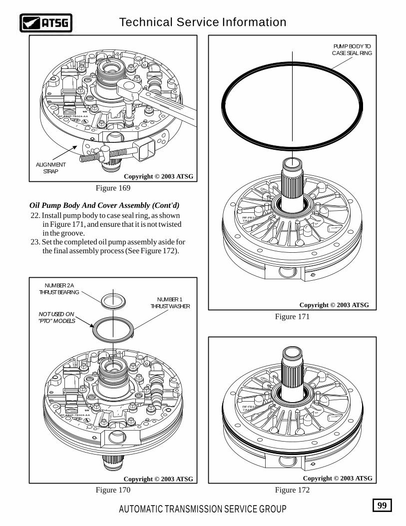
FordFord
RF-F81P-7B324-AA
107
98
KXV9.8
KXV9.8
KXV9.8
KXV9.8
KXV9.8
KXV9.8
KXV9.8
KXV9.8KXV
9.8
KXV9.8
KXV9.8
FordFord
RF-F81P-7B324-AA
107
98
KXV9.8
KXV9.8
KXV9.8
KXV9.8
KXV9.8
KXV9.8
KXV9.8
KXV9.8KXV
9.8
KXV9.8
KXV9.8
AUTOMATIC TRANSMISSION SERVICE GROUP
Technical Service Information
99
Copyright © 2003 ATSG
Copyright © 2003 ATSG
RF-F81P7A105-AA
Ford
Copyright © 2003 ATSG
RF-F81P7A105-AA
Ford
Copyright © 2003 ATSG
Figure 170 Figure 172
Figure 171
Figure 169
NUMBER 2ATHRUST BEARING
NUMBER 1THRUST WASHER
PUMP BODY TOCASE SEAL RING
ALIGNMENTSTRAP
NOT USED ON"PTO" MODELSNOT USED ON"PTO" MODELS
Oil Pump Body And Cover Assembly (Cont'd)
22. Install pump body to case seal ring, as shown in Figure 171, and ensure that it is not twisted in the groove. 23. Set the completed oil pump assembly aside for the final assembly process (See Figure 172).

FORD 4R100MAIN, LOWER, AND ACCUMULATOR VALVE BODIES DISASSEMBLED
12
67
89 3
4
5
RF-F6TP-
7A092-AB
1112
13
14
15
16
2122
2324
2526
27
28 29 30
3132
33
3435
3637
3839
4041
42
43
44
171819
20
1210
46
47
48
49
5051
525354
55
56
5758
5960
61
62
63
64
65
6667
6869
70
71
72
73
Figure 173
AUTOMATIC TRANSMISSION SERVICE GROUP
Technical Service Information
100
Copyright © 2003 ATSG
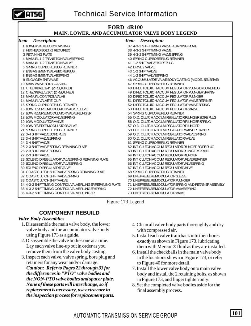
FORD 4R100MAIN, LOWER, AND ACCUMULATOR VALVE BODY LEGEND
Item ItemDescription Description 1 LOWER VALVE BODY CASTING 2 HEX HEAD BOLT, (2 REQUIRED) 3 RETAINING PLATE 4 MANUAL 1-2 TRANSITION VALVE SPRING 5 MANUAL 1-2 TRANSITION VALVE 6 SPRING CLIP BORE PLUG RETAINER 7 ENGAGEMENT VALVE BORE PLUG 8 ENGAGEMENT VALVE SPRING 9 ENGAGEMENT VALVE 10 MAIN VALVE BODY CASTING 11 CHECKBALL 1/4", (2 REQUIRED) 12 CHECKBALL 5/16", (2 REQUIRED) 13 MANUAL CONTROL VALVE 14 MANUAL VALVE "E" CLIP 15 SPRING CLIP BORE PLUG RETAINER 16 LOW REVERSE MODULATOR VALVE SLEEVE 17 LOW REVERSE MODULATOR VALVE PLUNGER 18 LOW MODULATOR VALVE SPRING 19 LOW MODULATOR VALVE 20 LOW REVERSE MODULATOR VALVE 21 SPRING CLIP BORE PLUG RETAINER 22 3-4 SHIFT VALVE BORE PLUG 23 3-4 SHIFT VALVE SPRING 24 3-4 SHIFT VALVE 25 2-3 SHIFT VALVE SPRING RETAINING PLATE 26 2-3 SHIFT VALVE SPRING 27 2-3 SHIFT VALVE 28 SOLENOID REGULATOR VALVE SPRING RETAINING PLATE 29 SOLENOID REGULATOR VALVE SPRING 30 SOLENOID REGULATOR VALVE 31 COAST CLUTCH SHIFT VALVE SPRING RETAINING PLATE 32 COAST CLUTCH SHIFT VALVE SPRING 33 COAST CLUTCH SHIFT VALVE 34 4-3-2 SHIFT TIMING CONTROL VALVE PLUNGER RETAINING PLATE 35 4-3-2 SHIFT TIMING CONTROL VALVE PLUNGER SPRING 36 4-3-2 SHIFT TIMING CONTROL VALVE PLUNGER
37 4-3-2 SHIFT TIMING VALVE RETAINING PLATE 38 4-3-2 SHIFT TIMING VALVE 39 4-3-2 SHIFT TIMING VALVE SPRING 40 SPRING CLIP BORE PLUG RETAINER 41 1-2 SHIFT VALVE BORE PLUG 42 DRIVE 2 VALVE 43 1-2 SHIFT VALVE 44 1-2 SHIFT VALVE SPRING 46 ACCUMULATOR VALVE BODY CASTING (MODEL SENSITIVE) 47 SPRING CLIP BORE PLUG RETAINER 48 DIRECT CLUTCH ACCUM REGULATOR PLUNGER BORE PLUG 49 DIRECT CLUTCH ACCUM REGULATOR PLUNGER SPRING 50 DIRECT CLUTCH ACCUM REGULATOR PLUNGER 51 DIRECT CLUTCH ACCUM REGULATOR VALVE RETAINER 52 DIRECT CLUTCH ACCUM REGULATOR VALVE SPRING 53 DIRECT CLUTCH ACCUM REGULATOR VALVE 54 SPRING CLIP BORE PLUG RETAINER 55 O.D. CLUTCH ACCUM REGULATOR PLUNGER BORE PLUG 56 O.D. CLUTCH ACCUM REGULATOR PLUNGER SPRING 57 O.D. CLUTCH ACCUM REGULATOR PLUNGER 58 O.D. CLUTCH ACCUM REGULATOR VALVE RETAINER 59 O.D. CLUTCH ACCUM REGULATOR VALVE SPRING 60 O.D. CLUTCH ACCUM REGULATOR VALVE 61 SPRING CLIP BORE PLUG RETAINER 62 INT. CLUTCH ACCUM REGULATOR PLUNGER BORE PLUG 63 INT. CLUTCH ACCUM REGULATOR PLUNGER SPRING 64 INT. CLUTCH ACCUM REGULATOR PLUNGER 65 INT. CLUTCH ACCUM REGULATOR VALVE RETAINER 66 INT. CLUTCH ACCUM REGULATOR VALVE SPRING 67 INT. CLUTCH ACCUM REGULATOR VALVE 68 SPRING CLIP BORE PLUG RETAINER 69 LINE PRESSURE MODULATOR SLEEVE 70 LINE PRESSURE MODULATOR PLUNGER 71 LINE PRESSURE MODULATOR SPRING AND RETAINER ASSEMBLY 72 LINE PRESSURE MODULATOR VALVE SPRING 73 LINE PRESSURE MODULATOR VALVE
AUTOMATIC TRANSMISSION SERVICE GROUP
Technical Service Information
101
Valve Body AssembliesCOMPONENT REBUILD
Figure 173 Legend
1. Disassemble the main valve body, the lower valve body and the accumulator valve body using Figure 173 as a guide. 2. Disassemble the valve bodies one at a time. Lay each valve line-up out in order as you remove them from the valve body casting. 3. Inspect each valve, valve spring, bore plug and retainers for any wear and/or damage. Caution: Refer to Pages 22 through 33 for the differences in "PTO" valve bodies and the NON-PTO valve bodies and spacer plate. None of these parts will interchange, so if replacement is necessary, use extra care in the inspection process for replacement parts.
4. Clean all valve body parts thoroughly and dry with compressed air. 5. Install each valve train back into their bores exactly as shown in Figure 173, lubricating them with Mercon® fluid as they are installed. 6. Install the checkballs in the main valve body in the locations shown in Figure 173, or refer to Figure 40 for more detail. 7. Install the lower valve body onto main valve body and install the 2 retaining bolts, as shown in Figure 173, and finger tighten only. 8. Set the completed valve bodies aside for the final assembly process.

AUTOMATIC TRANSMISSION SERVICE GROUP
Technical Service Information
102
FINAL ASSEMBLYInternal Case Components
102
103
105
104
Figure 174
Copyright © 2003 ATSG
102 REAR CARRIER TO REVERSE HUB RETAINING SNAP RING 103 NUMBER 10B THRUST WASHER 104 6 PINION REAR PLANETARY CARRIER ASSEMBLY
1. Rotate the pre-assembled case assembly in the fixture so bell housing is facing up, as shown in Figure 174. 2. Install the pre-assembled rear planetary carrier with the washers secured with Trans-Jel® into the reverse hub, as shown in Figure 174, and rotate into position.
3. Install the rear carrier retaining snap ring, into the reverse clutch hub, as shown in Figure 174, and ensure it is fully seated. Note: The reverse hub may have to be raised up slightly to gain access to the snap ring groove in the reverse clutch hub. 4. Install the pre-assembled direct clutch, forward clutch and sun shell assembly using installation tool, as shown in Figure 175, by rotating into position until fully seated. 5. Remove the T89T-70010-E installation tool. 6. Install intermediate band assembly, as shown in Figure 175, and ensure engagement on the case band anchor. You may want to install the intermediate servo piston at this time to help hold the band in position.
Copyright © 2003 ATSG
INTERMEDIATEBAND ASSEMBLY
PRE-ASSEMBLEDDIRECT CLUTCH,
FORWARD CLUTCHAND SUN SHELL
ASSEMBLY
INSTALLATION TOOLT89T-70010-E
Figure 175

AUTOMATIC TRANSMISSION SERVICE GROUP
Technical Service Information
103
Figure 176
Copyright © 2003 ATSG
52 INTERMEDIATE CLUTCH FRICTION PLATES 53 INTERMEDIATE CLUTCH STEEL PLATES 54 INTERMEDIATE CLUTCH BACKING PLATE
54
GAPS IN THE6 AND 12 O'CLOCK
POSITIONS
GAPS IN THE6 AND 12 O'CLOCK
POSITIONS
52
53
Copyright © 2003 ATSG
Figure 177
46
48
49
46 INTERMEDIATE CLUTCH PISTON RETURN SPRING 48 CENTER SUPPORT ASSEMBLY 49 NUMBER 6 THRUST WASHER, CENTER SUPPORT
FINAL ASSEMBLYInternal Case Components (Cont'd)
7. Install the intermediate clutch backing plate, as shown in Figure 176, with the gaps in the steel plates at the 6 and 12 o'clock positions in case. 8. Install the intermediate clutch plates, as shown in Figure 176, beginning with a friction plate and alternating with steel plates until you have the proper amount installed. 9. Again the gaps in the steel plates should be at the 6 and 12 o'clock positions in the case.
10. Install pre-assembled center support assembly, as shown in Figure 177, ensuring that the number 6 thrust washer is in place, and align the feed holes. 11. Loosely install the two center support feedbolts as shown in Figure 178. 12. Install intermediate clutch piston return spring, as shown in Figure 177, with one spring tab at the 6 o'clock position.
Continued on Page 104.

AUTOMATIC TRANSMISSION SERVICE GROUP
Technical Service Information
104
FINAL ASSEMBLYInternal Case Components (Cont'd)
Figure 178 Figure 179
40
42
Copyright © 2003 ATSG
40 INTERMEDIATE/OVERDRIVE CYLINDER SNAP RING 42 INTERMEDIATE/OVERDRIVE CYLINDER ASSEMBLY
Copyright © 2003 ATSG
CENTER SUPPORTFEED BOLTS
OVERDRIVECYLINDERFEED BOLT
13. Install pre-assembled intermediate/overdrive cylinder assembly, as shown in Figure 179, and align the feed hole. 14. Place the snap ring into the case and install the clutch spring compressor tool 307-S223, as shown in Figure 180, and tighten the center bolt in the tool to 7 N·m (65 in.lb.). 15. Install the snap ring into the case groove with the gap at 6 o'clock (bottom) position in case.
16. Ensure that the snap ring is fully seated and remove the clutch spring compressor tool. 17. Loosely install a new overdrive clutch cylinder feedbolt as shown in Figure 178. 18. Since we are building the "PTO" version, we must now install the overdrive clutch pack as the overdrive clutches will not pass by the PTO gear on the coast clutch housing.
Continued on Page 105.

AUTOMATIC TRANSMISSION SERVICE GROUP
Technical Service Information
105
Figure 181
Internal Case Components (Cont'd)
TIGHTEN CENTERBOLT TO 7 N·m
(65 IN.LB.)
CLUTCH SPRINGCOMPRESSOR PLATE
CLUTCH SPRINGCOMPRESSOR BAR
CLUTCH SPRINGFIXTURE
Figure 180
Copyright © 2003 ATSG
31
34
"DIMPLE"
3536
31 OVERDRIVE CLUTCH BACKING PLATE SNAP RING (SELECTIVE) 34 OVERDRIVE CLUTCH BACKING PLATE 35 OVERDRIVE CLUTCH FRICTION PLATES
19. With the units that are not equipped with PTO, the procedure would be the same as E4OD. 20. Install the overdrive clutch pack into the case, as shown in Figure 181, beginning with a steel plate and alternating with friction plates, until you have installed the proper amount. Note: The number of overdrive plates is model sensitive and may vary from illustration. 21. Install the overdrive clutch backing plate on top of the last friction plate, with the "dimple" facing up and in the 12 o'clock (top) position in the case (See Figure 181). 22. Install overdrive clutch backing plate selective snap ring, as shown in Figure 181, and ensure that it is fully seated in case groove, with the snap ring gap at the 6 o'clock position.
Continued on Page 106.
FINAL ASSEMBLY

AUTOMATIC TRANSMISSION SERVICE GROUP
Technical Service Information
106
FINAL ASSEMBLYInternal Case Components (Cont'd)
Figure 182 Figure 183
Continued on Page 107.
Copyright © 2003 ATSG
NUMBER 5THRUST BEARING
23. Measure the overdrive clutch clearance using a feeler gauge between the selective snap ring and the backing plate (See Figure 182). 24. Refer to Figure 182 for the specification as the 2 plate and 3 plate stacks are different. 25. Change the selective snap ring as necessary to obtain the proper clearance. The selective snap rings available are listed in Figure 182, along with the OEM part number. 26. Install the pre-assembled coast clutch housing and overdrive gearset as an assembly using the required installation tool 307 S383, as shown in Figure 183. Ensure that the number 5 thrust bearing is still in place on center shaft. Caution: The overdrive one-way roller clutch may be damaged if this tool is not used on the "PTO" equipped transmissions 27. The assembly will have to be rotated back and forth to engage the center shaft splines and all of the overdrive friction plates, and extra care must be used during installation to avoid any damage until fully seated.
"REQUIRED"ASSEMBLY TOOL
307 S383
PRE-ASSEMBLEDCOAST CLUTCH ANDOVERDRIVE GEARSET
2 PLATE
3 PLATE
0.68 - 1.33mm(0.27" - 0.52")
0.81 - 1.47mm(0.32" - 0.58")
Selective Snap Rings Available1.95 - 2.05mm (.077" - .081") = E9TZ-7B421-BA2.50 - 2.60mm (.098" - .102") = E9TZ-7B421-CA3.00 - 3.10mm (.118" - .122") = E9TZ-7B421-DA3.50 - 3.60mm (.138" - .142") = E9TZ-7B421-EA
OVERDRIVE CLUTCH CLEARANCE

7 OIL PUMP ASM. RETAINING BOLTS, M8 X 1.25 X 65 (9 REQ.) 9 OIL PUMP AND COVER ASSEMBLY 10 NUMBER 1 THRUST WASHER (USED NON-PTO MODELS ONLY) 11 OIL PUMP ASSEMBLY TO CASE GASKET 13 NUMBER 2 THRUST BEARING, PUMP TO O.D. SUN GEAR
AUTOMATIC TRANSMISSION SERVICE GROUP
Technical Service Information
107
Figure 185
Internal Case Components (Cont'd)
Figure 184
28. After coast clutch is fully seated, remove the installation tool. 29. Install an alignment dowel in one of the pump holes in case, as shown in Figure 184. 30. Install the input shaft into transmission, to also help with alignment concerns (See Figure 184). 31. Install a new oil pump to case gasket on case surface, as shown in Figure 185, and use small amount of Trans-Jel® to help secure in place. 32. Install the pre-assembled oil pump assembly, ensuring the number 2 thrust bearing is secure with Trans-Jel® (See Figure 185). 33. Ensure that the number 1 thrust washer is held in place with Trans-Jel®, if it is used. Note: The number 1 thrust washer is not used on "PTO" models. 34. Fully seat the pump assembly using only hand pressure. Do not use the bolts to pull the pump assembly into the case. 35. Install new washers on pump bolts and install, as shown in Figure 185, hand tight only.
Continued on Page 108.
FINAL ASSEMBLY7
9
11
10
13
INPUTSHAFT
ALIGNMENTDOWEL
Copyright © 2003 ATSGCopyright © 2003 ATSG
RF-F81P7A105-AA
Ford
KXV9.8
KXV9.8
KXV9.8
KXV9.8
KXV9.8
KXV9.8
KXV9.8KXV
9.8
KXV9.8
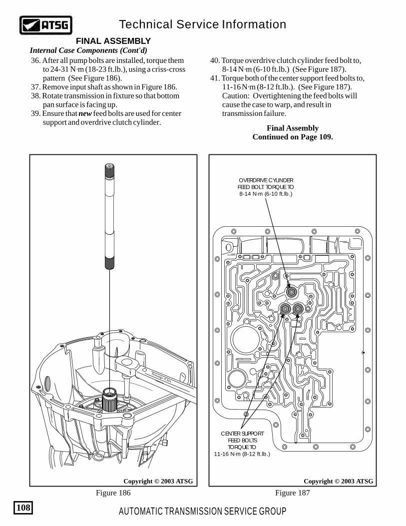
AUTOMATIC TRANSMISSION SERVICE GROUP
Technical Service Information
108
FINAL ASSEMBLYInternal Case Components (Cont'd)
Figure 186 Figure 187
Copyright © 2003 ATSG
Snap-On
36. After all pump bolts are installed, torque them to 24-31 N·m (18-23 ft.lb.), using a criss-cross pattern (See Figure 186). 37. Remove input shaft as shown in Figure 186. 38. Rotate transmission in fixture so that bottom pan surface is facing up. 39. Ensure that new feed bolts are used for center support and overdrive clutch cylinder.
40. Torque overdrive clutch cylinder feed bolt to, 8-14 N·m (6-10 ft.lb.) (See Figure 187). 41. Torque both of the center support feed bolts to, 11-16 N·m (8-12 ft.lb.). (See Figure 187). Caution: Overtightening the feed bolts will cause the case to warp, and result in transmission failure.
Copyright © 2003 ATSG
CENTER SUPPORTFEED BOLTSTORQUE TO
11-16 N·m (8-12 ft.lb.)
OVERDRIVE CYLINDERFEED BOLT. TORQUE TO8-14 N·m (6-10 ft.lb.)
Final AssemblyContinued on Page 109.

AUTOMATIC TRANSMISSION SERVICE GROUP
Technical Service Information
109
Figure 190
Figure 189
Bottom Pan Components
Figure 188
Continued on Page 110.
FINAL ASSEMBLY
Copyright © 2003 ATSG
.312" DIAMETER RUBBERCHECKBALLS
.312" DIA. RUBBERCHECKBALLSEPC BLOW-OFF
LOCATION
6262
Copyright © 2003 ATSG
182
183
55
55 MANUAL INTERMEDIATE SERVO ASSEMBLY 182 EPC BLOW-OFF BALL, .250" DIAMETER STEEL BALL 183 EPC BLOW-OFF SPRING
6262
Copyright © 2003 ATSG
U P
189
188
185
184
184 SPACER PLATE TO CASE GASKET 185 SPACER PLATE 188 SPACER PLATE REINFORCING PLATE 189 REINFORCING PLATE RETAINING BOLT, M6 X 1.0 X 42 (3)
1. Install eight (8) 5/16" diameter checkballs in their case pockets, as shown in Figure 188. 2. Install EPC blow-off spring and .250" diameter steel ball on top of spring, in location shown in Figures 188 and 189. 3. Install the manual intermediate servo piston, as shown in Figure 189, and ensure engagement with the target area on manual band. 4. Install new spacer plate to case gasket on case surface, as shown in Figure 190. 5. Install spacer plate, reinforcing plate and the 3 retaining bolts, as shown in Figure 190, and hand tighten only at this time. Note: The stamped word "UP" on reinforcing plate should be facing up.

AUTOMATIC TRANSMISSION SERVICE GROUP
Technical Service Information
110
Figure 192
Figure 191
Figure 193
6262
U P
Copyright © 2003 ATSG
187
186
186 SPACER PLATE TO MAIN VALVE BODY GASKET 187 SOLENOID SCREEN ASSEMBLY
6262
U P
RETAININGBOLTS (9)
SOLENOIDBODY ASSEMBLY "O" RING
Copyright © 2003 ATSG
RETAINING NUT
6262
U PUPPER AND LOWERMAIN VALVE BODIES
Copyright © 2003 ATSG
RETAINING BOLTS (14)
RETAINING NUTS (2)
Bottom Pan Components (Cont'd)
Continued on Page 111.
FINAL ASSEMBLY
6. Install the solenoid screen into the spacer plate, as shown in Figure 191, and rotate clockwise to lock in place. 7. Install the spacer plate to valve body gasket on spacer plate, as shown in Figure 191. 8. Install new "O" ring seal on the solenoid case connector, as shown in Figure 192, lube the "O" ring with Trans-Jel®, and install solenoid body (See Figure 192). 9. Install the nine solenoid body bolts and the one nut, as shown in Figure 192, and hand tighten only at this time. Note: Refer to Valve Body Bolt Chart found on Page 116 for proper locations. 10. Install the pre-assembled upper and lower main valve bodies, as shown in Figure 193, ensuring that manual valve is engaged on manual lever. 11. Install the 14 valve body retaining bolts and the two nuts, as shown in Figure 193, and hand tighten only at this time. Note: Refer to Valve Body Bolt Chart found on Page 116 for proper locations.
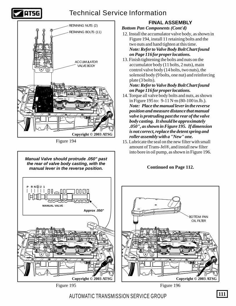
6262
U P
AUTOMATIC TRANSMISSION SERVICE GROUP
Technical Service Information
111
Figure 196Figure 195
Figure 194
Copyright © 2003 ATSG Copyright © 2003 ATSG
6262
U P
BOTTOM PANOIL FILTER
Copyright © 2003 ATSG
6262
U P
ACCUMULATORVALVE BODY
RETAINING NUTS (2)
RETAINING BOLTS (11)Bottom Pan Components (Cont'd)
Continued on Page 112.
FINAL ASSEMBLY
12. Install the accumulator valve body, as shown in Figure 194, install 11 retaining bolts and the two nuts and hand tighten at this time. Note: Refer to Valve Body Bolt Chart found on Page 116 for proper locations. 13. Finish tightening the bolts and nuts on the accumulator body (11 bolts, 2 nuts), main control valve body (14 bolts, two nuts), the solenoid body (9 bolts, one nut) and reinforcing plate (3 bolts). Note: Refer to Valve Body Bolt Chart found on Page 116 for proper locations. 14. Torque all valve body bolts and nuts, as shown in Figure 195 to: 9-11 N·m (80-100 in.lb.). Note: Place the manual lever in the reverse position and measure distance that manual valve is protruding past the rear of the valve body casting. It should be approximately .050", as shown in Figure 195. If dimension is not correct, replace the detent spring and roller assembly with a "New" one. 15. Lubricate the seal on the new filter with small amount of Trans-Jel®, and install new filter into bore in oil pump, as shown in Figure 196.
Snap-On
Manual Valve should protrude .050" pastthe rear of valve body casting, with themanual lever in the reverse position.
MANUAL VALVE
P R N 2D 1
Approx .050"

AUTOMATIC TRANSMISSION SERVICE GROUP
Technical Service Information
112
Figure 198
Figure 197
Figure 199
Bottom Pan Components (Cont'd)
External Components
Continued on Page 113.
FINAL ASSEMBLY
FINAL ASSEMBLY
Copyright © 2003 ATSG
6262
U P
PAN BOLTS (20) BOTTOMPAN
PAN GASKET
Copyright © 2003 ATSG
RFF81P-7006-BA
Ford
98
XW4P-AC
RJL-B
004361
BD-9C17
Ford
DIGITAL TRANSMISSIONRANGE SENSOR
RETAININGBOLTS (2)
"With" PTO OPTIONSTAMPED F81P-AA
"Without" PTO OPTIONSTAMPED F75P-BB
FORD PART NUMBERF81Z-7A256-AA
FORD PART NUMBERF7UZ-7A256-BB
FORD 4R100MANUAL SHIFT LEVERS
16. Install a new pan gasket on case surface, as shown in Figure 197. 17. Install the bottom pan on top of pan gasket, as shown in Figure 197. 18. Install the twenty (20) pan bolts, as shown in Figure 197, and torque all bottom pan bolts to, 14-16 N·m (10-12 ft.lb.). 19. Rotate transmission in fixture so bottom pan is facing down, as shown in Figure 199.
1. The manual shift levers are also model sensitive as shown in Figure 198. Ensure that you have the proper manual shift lever for the model that you are building. 2. Install the Digital Transmission Range (DTR) sensor, as shown in Figure 199, install 307-351 alignment tool (or equivalent). 3. Install the two sensor retaining bolts, as shown in Figure 199, and torque retaining bolts to, 8-10 N·m (71-88 in.lb.).
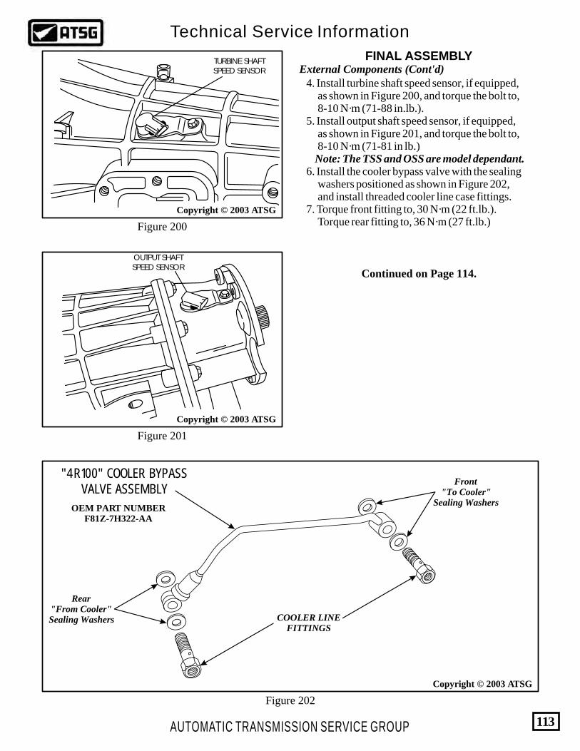
AUTOMATIC TRANSMISSION SERVICE GROUP
Technical Service Information
113
Figure 202
Figure 201
Figure 200
Continued on Page 114.
Copyright © 2003 ATSG
Copyright © 2003 ATSG
OUTPUT SHAFTSPEED SENSOR
Copyright © 2003 ATSG
TURBINE SHAFTSPEED SENSOR External Components (Cont'd)
FINAL ASSEMBLY
4. Install turbine shaft speed sensor, if equipped, as shown in Figure 200, and torque the bolt to, 8-10 N·m (71-88 in.lb.). 5. Install output shaft speed sensor, if equipped, as shown in Figure 201, and torque the bolt to, 8-10 N·m (71-81 in lb.) Note: The TSS and OSS are model dependant. 6. Install the cooler bypass valve with the sealing washers positioned as shown in Figure 202, and install threaded cooler line case fittings. 7. Torque front fitting to, 30 N·m (22 ft.lb.). Torque rear fitting to, 36 N·m (27 ft.lb.)
OEM PART NUMBERF81Z-7H322-AA
"4R100" COOLER BYPASSVALVE ASSEMBLY
Front"To Cooler"
Sealing Washers
Rear"From Cooler"Sealing Washers COOLER LINE
FITTINGS

AUTOMATIC TRANSMISSION SERVICE GROUP
Technical Service Information
114
Figure 203
Figure 204 Figure 205
External Components (Cont'd)FINAL ASSEMBLY
8. Remove the transmission from bench fixture and set on flat work surface (See Figure 203). 9. Install the input shaft, as shown in Figure 203, with the long spline end going in first. 10. Lubricate the converter hub with Mercon® fluid XT-2-QDX, or equivalent, as shown in Figure 204.
11. Install torque converter and check the seating by placing a straight-edge across the front of case, as shown in Figure 205. 12. Ensure that there is a gap between the converter pilot face and the straight-edge, as shown in Figure 205.
Copyright © 2003 ATSG
RFF81P-7006-BA
Ford
Ford
98
XW4P-AC
RJL-B
004361
BD-9C17
INPUT SHAFT
LONGER SPLINES
SPACE
CONGRATULATIONS-YOU ARE FINISHED!

AUTOMATIC TRANSMISSION SERVICE GROUP
Technical Service Information
115
Figure 206
Copyright © 2003 ATSG
TORQUE SPECIFICATIONS
DESCRIPTION N·m ft.lbs. in.lbs.
24-31
24-31
24-34
22-27
22-27
9-11
9-11
9-11
41-54
41-54
30
36
9-11
8-10
8-16
9-14
8-14
11-16
14-16
Oil Pump Assembly to Case (9)
Oil Pump Cover to Oil Pump Body (12)
Stator Shaft to Oil Pump Cover (3)
Center Support Feed Bolts (2)
Center Support to Center Support Hub Bolts (3)
Overdrive/Intermediate Cylinder Feed Bolt (1)
Valve Body and Solenoid Body Bolts and Nuts (All)
Spacer Plate Reinforcing Plate to Case (3)
Detent Spring to Case (1)
Inner Manual Valve Detent Lever Nut (1)
Transmission Range Sensor to Case (2)
Line Pressure Plug (1)
Low One-Way Roller Clutch Inner Race to Case (5)
Parking Pawl Abutment Plate to Case (1)
Parking Pawl Guide Plate to Case (2)
Extension Housing Bolts (9)
Front Cooler Line Connector to Case (1)
Rear Cooler Line Connector to Case (1)
Transmission Oil Pan to Case (20)
18-23
18-23
18-25
8-12
10-12
6-12
16-20
16-20
6-10
30-40
30-40
22
27
80-100
80-100
80-100
80-100
75-85
80-120

AUTOMATIC TRANSMISSION SERVICE GROUP
Technical Service Information
116
Figure 207
A
AA
AA
AAA
E
HG
G
A
B B
B B
J
J
J
BBB
BB
B
D
D
DD
D
D
DC
C
B
B
B
B
B
B
B
B
B
Lower V.B.to Case Nut
(1)
Main V.B.to Case Nut
(1)
8 mmHead
8 mmHead
Accum V.B.to Case Nut
(2)
Solenoid Bodyto Case Nut
(1)
8 mmHead
8 mmHead
AccumValve Body
to Case(11)
(42mm)
MainValve Body
to Case(7)
(42mm)
Lower V.B.to Main V.B.
(2)(35mm)
8 mmHead
8 mmHead
8 mmHead
9.8 9.8 9.8
Lower V.B.to Case
(7)(65mm)
8 mmHead
9.8
SolenoidBody(9)
(40mm)
30 TorxHead
"A" "B" "B" "C" "D" "E" "F" "G" "H"
"J"
ReinforcingPlate(3)
(16mm)
8 mmHead
9.8
VALVE BODY BOLT CHART
Copyright © 2003 ATSG
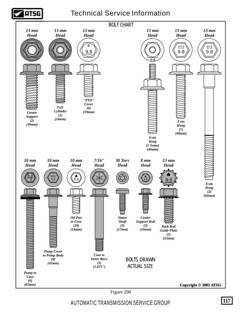
9.8
9.8
9.8
13 mmHead
13 mmHead
13 mmHead
ExtnHsng
(2)(92mm)
ExtnHsng
(7)(40mm)
ExtnHsng
(1 Some)(40mm)
13 mmHead
"PTO"Cover
(6)(19mm)
13 mmHead
13 mmHead
CenterSupport
(2)(30mm)
O.D.Cylinder
(1)(24mm)
9.8
9.8KXV
10 mmHead
Pump Coverto Pump Body
(9)(45mm)
9.8J
10 mmHead
Pump toCase(9)
(65mm)
10 mmHead
Oil Panto Case
(20)(14mm)
9.8
7/16"Head
Case toInner Race
(5)(1.875")
StatorShaft
(3)(17mm)
30 TorxHead
CenterSupport Hub
(3)(16mm)
8 mmHead
9.8
13 mmHead
9.8
Park RodGuide Plate
(2)(23mm)
BOLTS DRAWNACTUAL SIZE
BOLT CHART
Copyright © 2003 ATSG
AUTOMATIC TRANSMISSION SERVICE GROUP
Technical Service Information
117
Figure 208
Copyright © 2003 ATSG
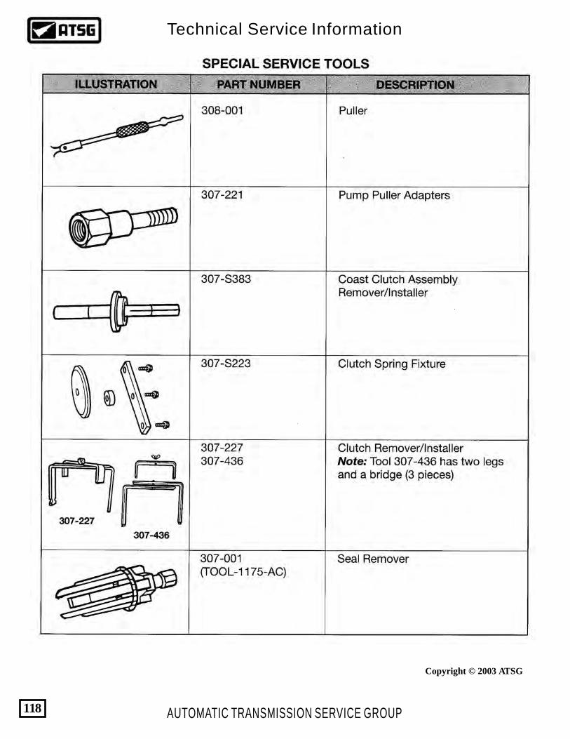
AUTOMATIC TRANSMISSION SERVICE GROUP
Technical Service Information
118
Copyright © 2003 ATSG
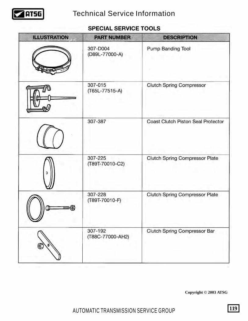
AUTOMATIC TRANSMISSION SERVICE GROUP
Technical Service Information
119
Copyright © 2003 ATSG

AUTOMATIC TRANSMISSION SERVICE GROUP
Technical Service Information
120
Copyright © 2003 ATSG
Related Documents