_!_i_iii_ii_i!_iii_;!i_{i_i_iii_i_ii_iiii!i_iiiiiiiiSi!i_ :, :: iii ' N95- 14481 ;: f S "-' ' .... ' .... CHALLENGES FOR THE AIRCRAFT STRUCTURAL INTEGRITY PROGRAM John W. Lincoln Aeronautical Systems Center Wright-Patterson Air Force Base, Ohio Thirty-six years ago the United States Air Force established the USAF Aircraft Structural /_i, Integrity Program (ASIP) because flight safety had been degraded by fatigue failures of operational aircraft. This initial program evolved, but has been stable since the issuance of MIL-STD-1530A in 1975. Today, the program faces new challenges because of a need to maintain aircraft longer in an environment of reduced funding levels. Also, there is increased pressure to reduce cost of the acquisition of new aircraft. It is the purpose of this paper to discuss the challenges for the ASIP and identify the changes in the program that will meet these challenges in the future. INTRODUCTION The modem era began for military aircraft in 1958 with the adoption of the USAF Aircraft Structural Integrity Program (ASIP). The ASIP defines all of the structurally related activities on an aircraft from initial development until retirement. Therefore, it is a program that is used in aircraft acquisition as well as for aging aircraft. The original objectives of the structural integrity program were to control structural failure of operational aircraft, determine methods of accurately predicting aircraft service life, and provide a design and test approach that will avoid structural fatigue problems in future weapon systems. These objectives still constitute the basis of the present ASIP. This program, however, was significantly changed as a result of the failure of an F-111 in 1969. This event ushered in the era of damage tolerance in the USAF. This change in approach prompted considerable research and development in area of fracture mechanics. In addition, since the damage tolerance approach forced the designer to better understand the stresses in the structure, emphasis was placed on the emerging finite element methods. These capabilities permitted the USAF to perform a damage tolerance assessment of all the major weapon systems in the inventory. This effort required over one million man-hours and every major manufacturer was involved with this activity. As a result of this activity, industry was able to develop the technology required for this type of analysis. This technology is also suitable for application to new aircraft developments. As a result, the USAF was able to include damage tolerance requirements in the specification for new aircraft procurement. The original damage tolerance requirements for the USAF were derived during the assessments performed on the C-5A and the B-1A in 1971 and 1972. These requirements were derived for monolithic (i.e., slow crack growth) structures, The failure of an F-4 wing on 23 January 1973 in a structural location that was believed to be fail-safe demonstrated to the USAF that a structure could not be fail-safe without an inspection program. This failure strongly influenced the damage tolerance requirements as formally established first in MIL-A-83444 and subsequently in AFGS-87221A. The technology for the analysis of fail- safe designs has evolved slowly, primarily because of the need for extensive finite element programs supported by expensive test programs. xl P_ PAGE I_tLANK NOT FP_M£D 409 brought to you by CORE View metadata, citation and similar papers at core.ac.uk provided by NASA Technical Reports Server

Welcome message from author
This document is posted to help you gain knowledge. Please leave a comment to let me know what you think about it! Share it to your friends and learn new things together.
Transcript
_._:_::_:_::::_...........:,,_: : :::::_::_:__:_:x____,_ ___::_L_,__,:::_:_:_:::__r:::_::__ _:_ _ __x :!_!__ii _ _i¸,!_i_!_!:i_i_i_i_!_!_!_i__ii_:i!_i_!_;_i_i_!__:i!i__!iii_;iii_:i!_i_!!_i!!_ii!_ii!i_:_;i!!i:_i_i_!i!iii_!!ii!i_ii!ii_!i!!iiiiiiiiiii_i!i!i_!_i_iii_ii_i!_iii_;!i_{i_i_iii_i_ii_iiii!i_iiiiiiiiSi!i_!iii_ii_!_i_!_!i_iii_i_i!i_iiiiiiiiiiiiiii_i!i_i_iiiiiiiii_iiiii!ii_iiiiiiiiiiiii_iii_iiii_
:, :: iii ' N95- 14481;: f S "-' ' .... ' ....
CHALLENGES FOR THE AIRCRAFT STRUCTURAL INTEGRITY PROGRAM
John W. Lincoln
Aeronautical Systems Center
Wright-Patterson Air Force Base, Ohio
Thirty-six years ago the United States Air Force established the USAF Aircraft Structural /_i,
Integrity Program (ASIP) because flight safety had been degraded by fatigue failures of
operational aircraft. This initial program evolved, but has been stable since the issuance of
MIL-STD-1530A in 1975. Today, the program faces new challenges because of a need to
maintain aircraft longer in an environment of reduced funding levels. Also, there is
increased pressure to reduce cost of the acquisition of new aircraft. It is the purpose of this
paper to discuss the challenges for the ASIP and identify the changes in the program that willmeet these challenges in the future.
INTRODUCTION
The modem era began for military aircraft in 1958 with the adoption of the USAF Aircraft
Structural Integrity Program (ASIP). The ASIP defines all of the structurally related
activities on an aircraft from initial development until retirement. Therefore, it is a program
that is used in aircraft acquisition as well as for aging aircraft. The original objectives of the
structural integrity program were to control structural failure of operational aircraft,
determine methods of accurately predicting aircraft service life, and provide a design and test
approach that will avoid structural fatigue problems in future weapon systems. These
objectives still constitute the basis of the present ASIP. This program, however, was
significantly changed as a result of the failure of an F-111 in 1969. This event ushered in the
era of damage tolerance in the USAF. This change in approach prompted considerable
research and development in area of fracture mechanics. In addition, since the damage
tolerance approach forced the designer to better understand the stresses in the structure,
emphasis was placed on the emerging finite element methods. These capabilities permitted
the USAF to perform a damage tolerance assessment of all the major weapon systems in the
inventory. This effort required over one million man-hours and every major manufacturer
was involved with this activity. As a result of this activity, industry was able to develop the
technology required for this type of analysis. This technology is also suitable for application
to new aircraft developments. As a result, the USAF was able to include damage tolerance
requirements in the specification for new aircraft procurement.
The original damage tolerance requirements for the USAF were derived during the
assessments performed on the C-5A and the B-1A in 1971 and 1972. These requirements
were derived for monolithic (i.e., slow crack growth) structures, The failure of an F-4 wingon 23 January 1973 in a structural location that was believed to be fail-safe demonstrated to
the USAF that a structure could not be fail-safe without an inspection program. This failure
strongly influenced the damage tolerance requirements as formally established first in
MIL-A-83444 and subsequently in AFGS-87221A. The technology for the analysis of fail-
safe designs has evolved slowly, primarily because of the need for extensive finite element
programs supported by expensive test programs.
xl
P_ PAGE I_tLANK NOT FP_M£D409
https://ntrs.nasa.gov/search.jsp?R=19950008067 2020-06-16T10:25:56+00:00Zbrought to you by COREView metadata, citation and similar papers at core.ac.uk
provided by NASA Technical Reports Server
ACOUISITION OF NEW AIRCRAFT
System acquisition programs in the U.S. Air Force typically go through a total of five
phases. These arc:
Concept Exploration and Definition
Demonstration/Validation
Engineering and Manufacturing Development
Production and Deployment
Operations and Support
To be successful in the development of a new aircraft, the structural integrity effort must
begin before the Engineering and Manufacturing Development phase of the program. In the
USAF, the structural activity starts in eamest in the Wright Laboratories even before the
Demonstration/Validation phase. However, it is normally the Demonstration/Validation
phase that is particularly critical for the transition of structural technology from the
laboratory to the aircraft. There are many examples of successful transitions of technology
from the laboratory to full-scale development. Many of these successes were derived from a
well-conceived plan or "road map" that formed the basis or criteria for technology transition.
In general, these road maps have included programs directed at several levels of technology
maturity. These levels are referred to as basic research, exploratory development, advanced
development and manufacturing technology development. Most of the advanced
development and manufacturing technology development program effort is directed towards
the demonstration of the technology by means of the manufacture and testing of a specificpiece of hardware.
A key element in the development of the road maps was a knowledge of the threats to
structural integrity from the environment in which the structure must be able to perform its
function. The understanding of these threats typically is derived from experiences with other
materials. There are situations, however, where a new material may be sensitive to a threat
that in the past has not been a major factor.
A study of those successful road maps for transition of technology to full-scale development
reveals that they had certain factors in common. These factors may be combined to form a
criterion for the transition process to be successful.
From a study of the successful transitions of structural technologies from the laboratory to
full-scale development it was found that five factors constituted a common thread amongthese successes. Also, it was found that these five factors were essential to the successful
completion of the tasks of the United States Air Force Structural Integrity Program (ASIP).These five factors are:
Stabilized material and/or material processes
Producibility
Characterized mechanical properties
410
: ,i _ i_ _ •i, _ •_ i _=_: _,_•_ _,:_ :_ _ _i__ _ • :_ _i: _ " _,
Predictability of structural performance
Supportability
In this listing there was no attempt to establish a ranking of importance of these factors. A
deficiency in any one of the factors could constitute a fatal defect. A description of each of
these five factors involved in the transition of structural technologies to full-scale
development is given in Reference 1.
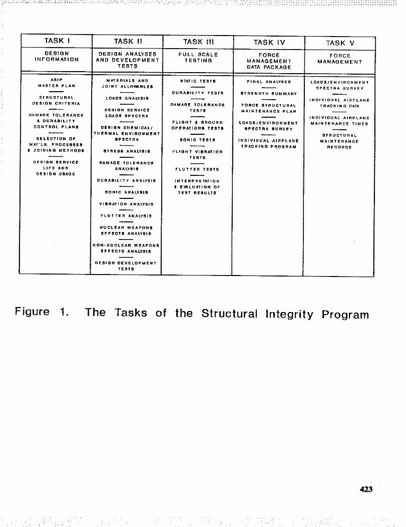
The current version of the ASIP includes five separate tasks that cover all aspects of the
development and support of an aircraft structure. These tasks, some of which are shown in
Figure 1, are identified as follows:
I. Design Information
II. Design Analyses and Development Tests
HI. Full-Scale Testing
IV. Force Management Data Package
V. Force Management
Within Task I (Design Information), there is an element called "Damage Tolerance and
Durability Control Plans." The damage tolerance control plans have proved to be effective
for inspection, tracking, and control of fracture critical parts. However, it has been found
that emphasis is needed to ensure that process controls are developed to enhance the
durability of the structure. Further, emphasis is needed to ensure that strength critical
structure (that is, buckling critical) has the proper controls to maintain dimensional
requirements.
It is planned to enlarge the scope of the durability control plans to require trade studies on
the use of process controls to detemfine the economic benefits of their use. This should
identify what parts over which it is important to exercise process controls. Further, there
will be an emphasis on the identification of acceptable tolerances on structure that is strength
critical. This will be based on analyses and the results of component tests to ensure that the
processes (including drawings, etc.) are able to produce the structure to the desiredtolerances.
Another important element of Task I is "Selection of Materials, Processes, and Joining
Systems." A key aspect of this element is selection of the corrosion protection system. The
corrosion problem is now becoming more acute in that the environmental protection laws
have el_ated the use of some of the standard corrosion inhibitors. Current and proposed
regulations eliminate volatile organic compounds, chromates, and carcinogens. New
environmentally safe methods are needed for corrosion inhibitors, paints, and paint strippingprocesses.
The "Design Service Life and Design Usage" element of Task I is heavily influenced by
weight changes of the aircraft. Weight control and reduction are almost guaranteed to be a
major part of any acquisition program. History has shown that contractor weight estimates
are typically optimistic. Also, for new aircraft the weight is not predictable fi'om existing
411
....._ _:::__ _ .... _ _ _:_/_ _ _ ;_ _ i̧ • • _i!!_!' ! _• !_i/•i !_•_•:__ _,:_! ii¸,I !•,_!_!_¸ ii_ii_ii!i_!i!i_?i_i!iii?i!_!_i!_!!_i!!!i_!i_!_i_!!_i_!_!(!!ii_i_!!i_!ii_!_i!!!i!_iiiiiii!iii!!_!_i!i_!_ii!i_i_i_i!i_iiiii!!_!i_:ii!!i_iiiiii!iii_!!!i_i!iii_
parametrics. There have been major errors in the prediction of the weight of propulsion and
some other subsystem weights. Another problem is that the weight used for the design of the
aircraft is the proposal weight rather than the weight that is expected when the aircraft has
reached the point of initial operational capability (IOC). It has been determined that weight
growth has typically been eight percent through the EMD phase of development. It has also
been found that prototyping does not reduce the weight growth in EMD. The weight savings
associated with contractor weight reduction programs are typically excessively optimistic.
Also, new technology and specification changes have only had a moderated impact on
weight growth. Further, the center of gravity control has been historically inconsistent.
The use of IOC weight for the design process would eliminate many of the problems with
weight growth. Further, early involvement of weight engineers would also provide the
oversight necessary to perform realistic estimates. Another initiative is to emphasize to
program managers that weight control is expensive and appropriate funding should beestablished.
In Task II there is an element called "Loads Analysis" and an element called "Stress
Analysis," both of which have caused considerable problems because of the tremendous
leverage they have in influencing the outcome of the damage tolerance analysis. It has been
found, in fact, that errors in the external loads have significantly impacted the life of aircraft
structures. In addition, the load and control system gain changes during EMD have led to
cost and schedule problems. In spite of all the buffet problems experienced on the F-15 and
F-18, the technology to accurately predict buffet loads is not available. With regard to
internal loads, it has been found that there have been significant differences in the quality of
finite element analyses. The complex internal load distributions found in the F-16 were
extremely difficult to simulate with current technology. Also, the state of the art for thedetermination of the thermal environment and the induced loads from that environment are
far from adequate.
It will likely remain difficult to attain the desired level of accuracy of the extemal loads.
The use of computational fluid mechanics should be emphasized for both steady state and
buffet loads in an attempt to improve accuracy and reduce the cost of wind tunnel testing
programs. There should be a program management initiative to develop a strategy for
obtaining an early freeze on both the configuration and control laws in EMD. The use of
flight load surveys that are more comprehensive should be a program goal. A deficient flight
loads survey was conducted on the A-7D. This led to ignorance about buffet loads on the
wings being a factor in the degradation of its life until the aircraft were nearing retirement.
The guidance in AFGS-87221A will be expanded for the purpose of using an experimental
approach for validation of the intemal loads in major component tests.
The "Design Service Loads Spectra" is another difficult area of Task III. Historically, the
usage for a new aircraft has been derived from usage data collected from existing operational
aircraft. In many cases, such as the F-16, this approach has been found to be very
unconservative. For this aircraft, the air-to-ground operation was considerably different than
that derived from an aircraft such as the F-4, for example. The maneuver freedom that is
412
/ii' !i iiill
given the pilot by the angle of attack limiter on the F-16 was believed to be a major factor in
this radical change.
Simulators have matured to the point that they are able to augment our understanding of the
usage for a new aircraft. The use of these devices should be included in the
demonstration/validation phase of acquisition for this purpose. Load limiters should be
installed on low g aircraft such as bombers and transport aircraft. The B-1 operational expe-
rience indicates that there are frequent exceedances of limit load factor. Also, on the B-1, it
was found that the design fuel reserves were considerably higher than that being experienced
in operational flying. Efforts should be made to work with the using command early in the
design program to establish realistic fuel reserves. As indicated above, a significant benefit
would be derived if aircraft were designed to IOC weights. The eight percent weight
increase that has been observed up to IOC translates into approximately a forty percent loss
in structural life. As part of the design process, trade studies will be performed to assess the
cost and schedule impact of incorporating a life margin in the design. Certainly, the past
experience of the Air Force indicates that an additional life margin is warranted.
In Task III of ASIP the major full-scale testing is accomplished. In static testing, it has been
found that stability failures are, by far, the most predominant mode of failure. Current
design practice and the pressure for weight savings have introduced unacceptable risk of
failure in full-scale testing. Further design development testing, which is one of the most
important elements of Task II, has been inadequate because of funding constraints. The ideal
analytical method for assessment of stability critical structure would be the nonlinear finite
element analysis. However, the state of the art of these analyses is not adequate at this time.
In many cases there is still an uncertainty of ten to fifteen percent in the ability to calculate
the true failure load. Clearly, the economic consequences of premature failure in static test
are unacceptable.
There will be an increased emphasis on design development testing to help eliminate
premature failures in full-scale static testing. The guidance for this will be placed in
AFGS-87221A. There will be developed a set of "best practice" rules for each type of
aircraft (i.e., fighters, bombers, transports). There will need to be trade studies performed
for structure that is expected to buckle below limit load to ensure that there is an economic
benefit from the use of such practice. The structure should be sized by analysis to withstand
160 percent of design limit load to enhance the ability of reaching 150 percent of designlimit load in test.
It has long been recognized that early testing of the full-scale structure was important.
Although the early airframes are generally not completely representative of the final
configurations, it is essential to get early information on deficiencies so they can be corrected
in production. The C-5A program is an example where both the static and fatigue tests were
performed after a significant number of production aircraft had been produced. Both of
these tests resulted in serious failures that occurred significantly short of the design
requirements. Because of the lateness of the tests, no changes were incorporated in any of
the production aircraft. As a result, the aircraft had to operate under severe restriction until
413
the entire fleet could be retrofitted with new wings. This, of course, was a major expense tothe government.
As indicated in Reference 2, a precept of the damage tolerance approach is the safety of the
aircraft and its economic operation should be independently proven. The damage tolerance
analysis, supported by testing, was the basis for safe operations and the full-scale durability
test was the basis for establishing the economic burden associated with service usage. The
damage tolerance analysis, supported by testing, has been effective in identifying areas of the
aircraft that could potentially cause a safety problem. It is desirable, however, to ensure they
have been identified through the full-scale durability test. The spectrum used by the USAF
for both the damage tolerance and durability analyses and testing is the expected average
usage. MIL-A-8867B(USAF) (Reference 3), which was released 22 August 1975, stated the
full scale durability test should be run for a minimum of two lifetimes unless the economic
life was reached prior to two lifetimes. The economic life of a structural component is
reached when that component is more economic to replace than repair. The economic life of
a component is extremely difficult to determine analytically. It may be, however,
demonstrated in durability testing. The same guidance that was given in
MIL-A-8867B(USAF) was given later in AFGS-87221A (Reference 4). There was no
guidance given, however, on the rationale for a need for testing for more than two lifetimes.
Consequently, it has been a program decision to test every aircraft for two lifetimes since
1975. All the known service experience demonstrates that an aircraft, after successfully
passing a two lifetime flight-by-flight durability test, will not reach its economic life in one
lifetime of service usage representative of the test spectrum. There is a question, however,
whether a full-scale durability test that simulates two lifetimes of planned operational usage
will adequately interrogate the structure to determine all the areas in all aircraft that could
potentially cause a safety problem.
A procedure is described in Reference 5 that is believed to be useful for establishing the
duration and/or the severity of testing that should be performed in a full-scale durability test
to ensure that all of the significant regions of the structure have been identified. It is based
primarily on data that could be derived from the existing analyses and development
testing. An example problem discussed in Reference 5 indicates that the length of testing
required using an average spectrum may be uneconomical. However, it appears practical to
increase the severity of the spectrum to provide for an adequate test and to complete the testin a timely manner.
The procedure also provides a basis for the success of the test. During or at the end of the
full-scale durability test, a crack may be found that initially appears to be significant. This
would not automatically indicate that the structure has failed to pass the test. It would,
however, indicate additional investigation should be undertaken. A fractographic
examination should be conducted to determine if the crack growth was faster than predicted.
If it was found to be faster than predicted based on the earlier analyses and tests, then an
investigation should be conducted to determine the local stresses and the fracture data (crack
growth rate) for the material used in the full-scale test at'tide. An assessment should also be
made to determine the implication on the damage tolerance derived inspection program.
414
.... ..... :iiiii!. . • : i • . _ i!i_! ii i!_̧ i i
After a study of all available information, a judgment is then made on the need for aircraft
modification or additional inspections to maintain economic and safe operational aircraft.
It is often found that a region or part of the aircraft needs to be redesigned based on failure in
the durability test. There may be occasions where the redesigned part is obviously robust
enough such that additional testing is not required. However, in general, the redesign should
be subjected to the same rigors of testing as the original airframe. This can often be
accomplished with a component test. However, there are some cases where this is not
practical. This retesting generally results in significant costs that were not part of the
original funding. The prospect of retesting the aircraft should be adequate motivation to take
the necessary precautions to ensure that the risk is low at the start of testing.
One of the critical elements of Task IV is the development of the Force Structural
Maintenance Plan (FSMP). This plan tells the maintainer of the aircraft how, when and
where the aircraft are to be inspected and/or modified as they proceed through their
operational lives. For new aircraft, the guidance in Reference 4 is to establish the stresses
such that no inspections are mandatory to provide flight safety. This means that the stresses
are established such that there are two lifetimes of slow crack growth capability from the
damage tolerance initial flaw to critical crack length. However, an inspection should be
developed that could be used in the case of usage severity or mass increases. For most
military aircraft, experience has shown that there is a considerable difference in usage
severity among the individual aircraft. The accounting for the actual usage of the aircraft is
determined by the individual aircraft tracking program and the loads/environment spectra
survey. These two elements work together to obtain an estimate of the stress spectra for a
number of control points in the structure. For aircraft that are designed according to the
damage tolerance philosophy, the generated stress spectrum is used to determine the time at
which the damage tolerance initial flaws would grow to critical. This time is divided by a
factor of two to determine the number of flight hours that the inspection should be
performed. For aircraft that are operated under a safe life approach, the tracking program is
used to determine, for the various tracking control points, the life expended relative to the
fatigue test demonstrated life. Another important element of Task IV is the "Strength
Summary." It is this report that provides the important structural characteristics, limitations,
and capabilities in terms of operational parameters. The durability, damage tolerance, and
static test results coupled with the results of instrumented ground and flight testing providethe basis for this document.
It is noted that the contractor typically performs the elements of Task IV of ASIP and the Air
Force normally performs the elements of Task V. However, there is a growing trend to
obtain contractor assistance in the performance of Task V. It is Task V, which continues
until the aircraft is retired where the effects of aging of the aircraft can emerge and incur a
significant additional maintenance burden.
AGING AIRCRAFT
As indicated above, two of the main products of the ASIP process are to develop strength
summary and operating restrictions report and to develop the force structural maintenance
415
plan. If there is a need to change either of these documents because of flight beyond design
usage that could introduce new critical areas, corrosion, widespread fatigue damage, or
repairs, then the aircraft is said to be aging.
Experience with operational aircraft has revealed they are typically not flown to the loading
spectrum for which they were designed. Data from flight load recorders have shown, in
general, that there are considerable differences in usage severity among aircraft with the
same designation. Further, it is often found the average aircraft usage is more severe than
originally perceived early in the design process. This problem is aggravated by the fact the
damage tolerance analysis may have not identified an area that would be a concern if the
aircraft usage was more severe than that assumed for design. Also, experience has shown the
mass of an aircraft increases as a result of additional equipment or modification after an
aircraft enters operational service. In addition, there are differences because (1) pilot
technique changes as they become more familiar with the aircraft, and (2) mission changes
because of new weapons and tactics. The aircraft-to-aircraft variability comes from several
sources such as base to base variations in distance to test ranges and training. These
experiences tend to degrade the capability of the full-scale durability test that consisted of
two lifetimes of average usage to identify all the areas of the aircraft that could potentially
cause a safety problem. Consequently, the structural engineer should, based on historical
evidence, make some allowances for increased usage severity occurring as a result of mission
severity changes and aircraft to aircraft variations in operational usage. To ensure aircraft
durability, this should be done both in the design of the aircraft and in the test. The
historical evidence of usage differences derived from changes in pilot technique and mission
changes is generally not easily translatable to new designs.
The study reported in Reference 6 found that corrosion damage to USAF aging aircraft
causes the most significant cost burden of any structurally related item. In this study, funded
by Warner Robins Air Logistics Center, the researchers found that the costs of corrosion to
the Air Force could be conservatively estimated at $700 million per year. This is the largest
maintenance cost of any structurally related item. In many cases the materials that were used
in these aircraft were driven by the need for improved performance and little attention was
given to the potential for corrosion and stress corrosion cracking damage. Further, when
many of these aircraft were built, the focus on corrosion protection was not what it is today.
Many of these early corrosion protection systems have broken down. In the open areas these
can be readily renewed. There is, however, no easy way to renew the corrosion protection
system in the joints. Experience with remanufacturing of aging aircraft has revealed that
joints that were not properly protected experience significant damage that results in costlymodifications.
It was indicated above that the corrosion problem is now becoming more acute in that the
environmental protection laws have eliminated the use of some of the standard corrosion
inhibitors. Another issue is that the nondestructive evaluation techniques are marginal. The
standards for corrosion damage are, at best, poorly defined such that characterization of
damage found is not well understood. Further, the predictive capability for corrosion is
basically nonexistent. This deficiency creates a real problem in the future years cost
prediction for structural maintenance.
416
i_ii!_i_ii_il_i_i__!:!i _!!_!_ii_!ii_!_____i_!_!!/_iili_!!_!__i_!_i_il¸ _̧!_/i?_i!! :! _ !_i! ! _i:_ii_ii!ii?_!!i_i!_i!i____il/i__i!_!!_i:_!/i!ii!:!_!i'_(!!_!i!!!i__!i!ii_i_i_//i ii!ii_!i_i/!!ii!!_i_iiii!i_!i!ii__!!_i_!ii!_ii_i!!!_!_ii_!_i_ii_i_iii_i_i!i!iiiii!i_iii_!iiiiiii!i_iiiiiii_i!i!_iiiiii_i_iii_ii_iii_iiiiiii_iii_ii_ii_iii_iiiiiiiiiiii_iiiiiiiiiiiiiiiii
One initiative that is believed to be needed is the establishment of an advisory council from
the Army, Navy, Air Force, FAA, and NASA to provide guidance on programs relating to
corrosion. This could provide the impetus to perform the necessary research and
development and develop the standards needed. Emphasis must be placed on providing thetools for nondestructive evaluation for corrosion in hidden areas of the structure. There is a
need to enforce the policy in the Air Force that corrosion damage will be fixed and not
allowed to jeopardize safe and economical operation. In addition, there is a need to
emphasize the need for the development of new corrosion protection systems that are
environmentally safe.
The USAF has undertaken a teardown of a KC-135 taken from service for the purpose of
assessing the extent of corrosion on these aircraft. The USAF owns approximately 700 of
these tanker aircraft and they are considered a national asset. It is essential that they remain
in the inventory well into the next century. Another goal of the program is to evaluate the
potential of nondestructive evaluation to detect hidden corrosion in the joints of the aircraft.
However, the main virtue of the program is that it has established the areas where corrosion
is a problem. If these areas are not given the proper maintenance action to correct these
problems, then the situation will only get worse and incur additional cost. It is essential that
a program be initiated now to correct this problem rather than waiting for the crisis that is
sure to occur.
For some of the older USAF aircraft that were not designed to the modem damage tolerance
requirements as detailed in Reference 7, there is a potential for cracking to be so widespread
in the structure that the application of the deterministic damage tolerance process may not
protect the safety of these aircraft. This situation could exist in monolithic structures. This,
in fact, did happen on the T-38 trainer aircraft. The analysis associated with the T-38 risk
assessment that was made to treat tiffs problem is described in Reference 8. However, the
prnnary concern is with structures that were initially designed to be fail safe. For these
structures, the occurrence of widespread fatigue damage can significantly degrade the fail
safety of the structure. This has been experienced on the KC-135, C-5A and the C-141
aircraft. The KC-135 and C-5A experiences are discussed in Reference 7. These aircraft
were subjected to teardown inspections and the results of these inspections were incorporated
in a risk assessment to quantify the time when the probability of failure, conditioned by the
fact there had been discrete source damage, become unacceptable.
In the case of the C-5A, it was judged that fail safety had been compromised if the
conditional failure probability on a single flight was greater than 10 -4. For that aircraft, the
critical area of the wing was the inner wing surface that was constructed with individual
panels that incorporated integral stringers. For this location, it was believed that the threat
was a loss of a wing panel from engine disintegration or from battle damage. For a given
aircraft, it is necessary that the conditional failure probability and the threat be determined
for each area. For example, for areas that are in the path of failed engine parts, the
penetrations of these parts would be the threat. The likelihood of occurrence may be
determined from the available statistics on in-flight engine failures. In other parts of the
aircraft, an evaluation must be made for the possibility of other threats, such as accidental
417
damage from manufacturing, maintenance, or ground handling. The threat assessments must
be made to ensure that the probability of catastrophic failure is maintained within an
acceptable bound. For the USAF, the acceptable bound is a catastrophic failure probability
of 10 -7. In the case of the C-5A, the time at which the joint probability of discrete source
damage and fatigue cracking exceeded 10 -7 was less than the time at which fatigue cracking
alone of the intact structure exceeded 10 -7 . However, in some cases, the threat of fatigue
cracking may be the dominant threat. This was found to be the case for the C-141 inner to
outer wing splice as demonstrated by Lockheed in their work documented in Reference 9. In
this case, the problem was the progressive failure of the structure because of fatigue
cracking. For any structure, both the external source damage case and the intact structurecase should be examined.
The USAF recognized the need for additional work in the area of risk assessment technology
for maintaining safety of operational aircraft. Consequently, the Wright Laboratories
sponsored a program in this area. The results of this program are documented in Reference
10. In this effort, the University of Dayton Research Institute developed the computer
program PROF (PRobability Of Fracture). The program may be used to evaluate
maintenance costs in addition to safety.
One of the primary inputs to the risk assessment approach to determine the onset of the time
to widespread fatigue damage is the distribution of cracks in the structure. Teardown
inspection of full-scale fatigue test articles or operational aircraft is believed to be the best
method currently available to obtain the data required to derive the probability distribution
function for equivalent initial cracks in each of the critical areas of the structure. The word
"critical" here refers to an area that could significantly contribute to the probability of failure.
The Wright Laboratories has sponsored considerable research effort in the determination ofinitial crack distributions in aircraft structures. Much of this effort was concentrated on the
interpretation of the cracks found in the teardown inspection of the F-16 wing after the
durability test had been performed. This program is reported in Reference 11.
The probabilistic approach also requires the stress density function for each critical area be
determined. The data from which the stress density function can be derived are available
through the usage information that is generated by the individual aircraft tracking programs
that is part of ASIP for USAF aircraft. The desired stress density function is the one for a
single flight of an aircraft selected at random. This may be easily derived from the stress
exceedance function that is developed as a part of the deterministic damage tolerance
analysis. The joint probability distribution of cracks and stress is computed and integrated
over the point set where the crack size has reached critical length. The result of this
calculation is the single flight probability of failure. The time at which the probability of
failure is unacceptable is the onset of widespread fatigue damage.
The damage scenarios in an airplane that could constitute widespread fatigue damage differ
depending on location in the aircraft. However, typically, they fall into two categories. The
first of these is multiple site damage that is characterized by cracks in multiple details in the
418
samestructural element. The secondis multiple elementdamagewherethere arecracks inmultiple structural elements. For the caseof fail safestructures,the emphasismust beplacedon the influence of elevatedstressesasaresult of discrete sourcedamage. Theseelevatedstresseshavebeenshownby testdataand analysesto significantly lower the crack sizeatwhich the structurewill fail by rapid fracture. If thesefailures cannot bearrested,then theaircraft will fail catastrophically. Eachof the potential failure scenariosmust beevaluatedtoensurethat they will not lead to total structural failure.
The previous efforts on this type of analysis have shown that it can readily be applied to the
structures where the concern is multiple element damage. This was the case, for example,
for the KC-135 and the C-5A. The application of the risk assessment technology to the case
of multiple site damage is very much the same as it is for the case of multiple element
damage. In the case of multiple site damage there will typically be a "boundary" that will
determine if the cracking has the potential to become catastrophic. For example in the case
of the fuselage lap splice, the boundary would be the crack stopper built into the structure at
the frame or between the frames and its surrounding structure. This crack arrest feature
protects the integrity of the structure. The condition of the crack stopper and its surrounding
structure (i.e., the boundary) will determine if the damage could propagate to catastrophic
failure. Therefore, the interest is primarily in the degradation of the boundary with time and
not the growth of the holes in the lap splice to link-up. When the problem is thought of in
this manner, it may be treated similarly to the multiple element damage problem. An
example of this was demonstrated by Lockheed in their work documented in Reference 9 on
the risk assessment of the inner to outer wing joint of the C-141 aircraft.
There must be an emphasis placed on the detection, through nondestructive evaluation, of
cracks that could be significant for determination of the onset of widespread fatigue damage.
As indicated above, there is a need to make an estimate of this onset based on probabilistic
assessment of cracking data derived from the teardown inspection of fatigue test articles or
operational aircraft. It must be recognized, however, that this is only an estimate. It is not
realistic to expect that this time could be determined with great accuracy even with the most
sophisticated fracture mechanics programs. The actual time may be either somewhat earlier
or later than this estimate. It is important, therefore, to be able to validate this prediction with
nondestructive evaluation. This task is made difficult by the fact that the size of defect to be
found is quite small. The experimental evidence to date indicates that cracks of the order of
two millimeters can significantly lower the fail safety capability of certain structural
configurations.
Traditionally, the repairs placed on aircraft have been designed based only on static strength
considerations. On some of the aging aircraft, however, the USAF has funded the effort for
the original equipment manufacturer to design the standard repairs to be damage tolerant.
This effort was a logical activity subsequent to the damage tolerance assessments that were
made for the intact structure. There is a need to reevaluate these repairs in light of the
emerging capability for composite repairs of metallic structure. There are numerous
applications currently of composite repairs in the USAF, in addition to the applications in
Australia and Canada. The applications made by the original equipment manufacturer
include the C-130, C-141, KC-135, and the B-1. The success of these applications has
419
.... • : • _ • _//:<_ !7 ¸ i<i< i _<i_! •_i_•: : :_' i i_< i<<<: C::_!i>:<!?!<TI_C_?!<<!:_:i/:!i_:_!!C7%_!i!ii_i!_!i_ii!i_i!_i!_!_!_!<!_!_!_!_k_ii_i_ii_!_i_!_!_i!_!_!i_i_!_i!j_ii_i!_i_!iiii_ii!_ii_iii_i_ii_ii_iii_iiiii_i_iii_i_iiiiii_iii_iiiiii_ii_iiii_iiiiiii!
motivated the USAF to spend the resources to fully exploit this technology. A significant
program in composite repair technology has been completed by the Wright Laboratories
Materials Directorate. This program provides the technology for routine repairs using
composite materials. The procedures have been established for successfully preparing the
surface for the bonding operation. It has been found that the additional technician training
required for making the patches is very little. Also, the technology requirements for the
design of the patch are not demanding. This technology is being used in a specific
application on the F-16. However, by far, the most significant accomplishment in the
application of the composite patches has been the patching of the weep hole cracks in the
lower surface of the C-141 lower inner wing surface. This problem forced the grounding of
almost all of the aircraft. This effort was able to restore the structural integrity of that wing
with minimum interference to the using command. The weep hole cracking problem on the
C-141 is discussed in some depth in Reference 12.
Another problem is the constraints placed on the ASIP managers by program management.
Program management faces pressures of schedule and cost that does not always permit
adequate attention to integrity concerns such as corrosion control. Also, these ASIP
managers are so burdened with detail maintenance problems they have little time to devote to
the consideration of broader issues for their aircraft. An example of a broader issue is the
determination of when to expect the onset of widespread fatigue damage such as that
revealed in the inner to outer wing joint of the C-141. Another example is the unanticipatedcracking in the A-7D wings that led to a structural failure in December of 1988. Still
another example is the identification of nondestructive inspection capability that will enable
them to inspect more accurately and economically in the future.
A particularly difficult problem for the ASIP is the procurement of aging off-the-shelf
aircraft. In the marketplace there are many used aircraft that could be purchased far below
the price of a new off-the-shelf aircraft. The reasons for the low price on these aircraft are
that they have overflown their design service life, they have corrosion problems, they have
widespread fatigue problems, and they have numerous repairs, many of which are not
damage tolerant. That is, they generally possess all of the ingredients, identified and
discussed above, to be classified as an aging aircraft. Unfortunately, many of these problems
can be hidden from view and the aircraft appear to be airworthy. Experience has shown that
significant problems do exist and the cost of refurbishing these aircraft is considerably aboveoriginal expectations.
Another problem with off-the-shelf aircraft is the lack of external and internal loads
information. This has, of course, been a chronic problem in the commercial world because
of the need to have an understanding of the loads to make repairs that are damage tolerant.
Since, in most cases, the original equipment manufacturer has not seen the benefit of
releasing loads information, a loads research program is needed to establish the methodologyto accomplish the task of providing this information.
Many of the aging military aircraft problems find an exact parallel in aging commercial
aircraft. It is prudent, therefore, that these problems be worked through the combined talents
420
i!iii___:__,:,:<..............,_:,_,:___:_::____< <_:_<___:_:_<:_:__ __:,__<_<<_<:_i__<i̧ i_<<_<<_i_!_i!__i!__i_i_<!!!_:_i_ii_<ii_ii!_<_i_i_!_!_!_i!i_i_!_i_i_i_iii_i!_i!_i_i_i_!ii_ii_!_i!i!i!_i!_i!i_i!_i_ii!_!_iii_i!i_i_iii_iii_i!i_iii_iiiiiii_i_iii_i!i!iiiiiiiiii_iii_iiii_iii!iii_iii_i!iii_iiiiiiiiiiiii_iii_ii_iiiii_iiiii
andresources of the Air Force, FAA and NASA. Efforts to date indicate that this approach
will be successful and most efficient in solving these complex problems.
CONCLUSIONS
The ASIP is a process that has enabled the safe and economic operation of military aircraft.
As an indicator of this success, the failure rate for all systems designed to and/or maintained
to the current policy is one aircraft lost due to structural reasons in more than ten million
flight hours. This is significantly less than the overall aircraft loss rate from all causes by
two orders of magnitude. This success, however, should not be used to indicate that there is
no need for continued vigilance in the treatment of aircraft structural problems. The success
of the program has, in fact, made it more difficult to obtain funding for research and
development in the structural area. It has also, at times, given program managers a falsesense about the remoteness of structural failures.
One of the major problems found in operations with aging aircraft is the cost associated with
corrosion damage. Unfortunately, the progress made in the recent past in the control of this
problem does not bode well for the future. This is especially true when one considers the
impact of new environmental laws that remove many of the corrosion fighting chemicals that
are currently used. Continued emphasis in research in the area of corrosion control is
certainly one area that could have significant benefit.
Another major problem is widespread fatigue damage in primary structural elements. There
will be costs incurred to establish an estimate of the time of onset of this problem. This will
need to be done through the analysis of data derived from teardown inspections of fatigue
test articles and/or of operational aircraft. These estimates will need to be corroborated
through the use of detail inspections of suspect structural elements. Once this onset time has
been reached, then there will be costs incurred by the modification of the aircraft to remove
this problem.
The severity of both of these problems is made worse today because of a lack of adequate
nondestructive evaluation techniques to look for corrosion damage in structural joints and to
fred the small cracks that would be the indicator of the onset of widespread fatigue damage.
It appears that the current efforts in research in nondestructive evaluation will produce the
technology for these problems. It remains to be seen if there is an economic motivation to
transition this technology from the laboratory to inspections of operational aircraft.
The Air Force will have increasing pressure to buy aircraft that have been certified by an
agency outside of the Air Force. It is the intent to judge these aircraft based on the content
of the ASIP. As has been done in the past, aircraft procured in this manner will be assessed
based on requirements under which they w.ere certified, how well their design missions meet
the Air Force requirements and the extent of their service experience. Additional structuraltesting and analysis will only be done where needed.
421
REFERENCES
1. Lincoln, J.W., "Structural Technology Transition to New Aircraft," Proceeding of the
14th Symposium of the International Committee on Aeronautical Fatigue," Ottawa, Ontario,
Canada, 1987.
2. Lincoln, J.W., "Damage Tolerance - USAF Experience," Proceeding of the 13th
Symposium of the International Committee on Aeronautical Fatigue," Pisa, Italy, 1985.
3. Department of the Air Force, "Airplane Strength and Rigidity Ground Tests," Military
Specification MIL-A-008867B(USAF), 1975.
4. Department of the Air Force, "Air Force Guide Specification, Aircraft Structures,
General Specification for," AFGS-87221A, 1990.
5. Lincoln, J.W., "Assessment of Structural Reliability Derived from Durability Testing,"
Proceeding of the 17th Symposium of the International Committee on Aeronautical Fatigue,"
Stockholm, Sweden, 1993.
6. Cooke, Garth E., et al, "A Study to Determine the Annual Direct Cost of Corrosion
Maintenance for Weapon Systems and Equipment in the United States Air Force," Final
Report on Contract #F09603-89-C-3016, WR-ALC/CNC, Robins AFB, GA.
7. Lincoln, J.W., "Risk Assessments-USAF Experience," Proceeding of the International
Workshop on Structural Integrity of Aging Airplanes, Atlanta, GA, March 31 - 2 April 1992.
8. Lincoln, J.W., "Risk Assessment of an Aging Military Aircraft," Journal of Aircraft,
Volume 22, Number 8, 1985.
9. Alford, R.E., Bell, R.P., Cochran, J.B., and Hammond, D.O., "C-141 W.S. 405 Risk
Assessment," Proceedings of the 1991 U.S.Ai.r Force Structural Integrity Conference,
WL-TR-92-4045, July 1992.
10. Berens, A.P., Hovey, P.W., and Skinn, D.A., "Risk Analysis for Aging Aircraft Fleets,"
WL-TR-91-3066, Wright Laboratory, Wright-Patterson AFB, OH, October 1991.
11. Manning, S.D., and Yang, J.N., "Advanced Durability Analysis," Vol 1-5,
AFWAL-TR-86-3017, Flight Dynamics Laboratory, Wright-Patterson AFB, OH July 1988.
12. Lincoln, J.W., "Considerations in the Service Life Extension Program for the C-141
Aircraft," Presented at the Intemational Pacific Air & Space Technology Conference,
Singapore, 14-18 February 1994.
422
TASK I TASK II TASK _!1 TASK IV TASK V
DESIGN
INFORMATION
ASlP
MASTER PLAN
STRUCTURAL
DESIGN CRITERIA
DAMAGE TOLERANCE
& DURABILITY
CONTROL PLANS
SELECTION OF
MAT'L8, PROCESSES
& JOINING METHODS
DESIGN SERVICE
LIFE AND
DESIGN USAGE
DESIGN ANALYSES
AND DEVELOPMENT
TESTS
MATERIALS AND
JOINT ALLOWABLES
LOADS ANALYSIS
DESIGN SERVICE
LOADS SPECTRA
DESIGN CHEMICAL/
THERMAL ENVIRONMENT
8PECTRA
STRESS ANALYSIS
DAMAGE TOLERANCE
ANALYSIS
DURABILITY ANALYSIS
SONIC ANALYSIS
VIBRATION ANALYSIS
FLUTTER ANALYSIS
NUCLEAR WEAPONS
EFFECTS ANALYSIS
NON-NUCLEAR WEAPONS
EFFECTS ANALYSIS
DESIGN DEVELOPMENT
TESTS
FULL _CALE
TESTING
STATIC TESTS
DURABILITY TESTS
DAMAGE TOLERANCE
TEST8
FLIGHT & GROUND
OPERATIONS TEST8
SONIC TESTS
FLIGHT VIBRATION
TESTS
FLUTTER TESTS
INTERPRETATION
& EVALUATION OF
TEST RESULTS
FORCE
MANAGEMENT
DATA PACKAG E
FINAL ANALYSES
STRENGTH SUMMARY
FORCE STRUCTURAL
MAINTENANCE PLAN
LOADS/ENVIRONMENT
SPECTRA SURVEY
INDIVIDUAL AIRPLANE
TRACKING PROGRAM
FORCE
MANAGEMENT
LOADS/ENVIRONMENT
SPECTRA SURVEY
INDIVIDUAL AIRPLANE
TRACKING DATA
INDIVIDUAL AIRPLANE
MAINTENANCE TIMES
STRUCTURAL
MAINTENANCE
RECORDS
Figure 1. The Tasks of the Structural Integrity Program
423
Related Documents


