Transient overvoltage protection — PRODUCT OVERVIEW IET Wiring regulations BS 7671 18th edition Amendment 2 (2022)

Welcome message from author
This document is posted to help you gain knowledge. Please leave a comment to let me know what you think about it! Share it to your friends and learn new things together.
Transcript
Transient overvoltage protection
— PRODUCT OVERVIEW
IET Wiring regulations BS 7671 18th editionAmendment 2 (2022)
4 I E T W I R I N G R EG U L ATI O N S B S 76 7 1 1 8TH ED IT I O N
— The IET Wiring Regulations require all new electrical system designs and installations, as well as alterations and additions to existing installations, to be assessed against key consequences caused by transient overvoltages and, where necessary, protected using appropriate surge protection measures (in the form of Surge Protection Devices SPDs).
3TR A NSIENT OV ER VO LTAG E PR OTEC TI O N - I NTR O D U C TI O N
—Transient overvoltage protectionIntroduction
Based on the IEC 60364 series, the 18th Edition of BS 7671 Wiring regulations covers the electrical installation of buildings including the use of surge protection.
The 18th Edition of BS 7671 applies to the design, erection and verification of electrical installations, and also to additions and alterations to existing installations. Existing installations that have been installed in accordance with earlier editions of BS 7671 may not comply with the 18th edition in every respect. This does not necessarily mean that they are unsafe for continued use or require upgrading.
A key update in the 18th Edition relates to Sections 443 and 534, which concern protection of electrical and electronic systems against transient overvoltages, either as a result of atmospheric origin (lightning) or electrical switching events.
Essentially the 18th Edition require all new electrical system designs and installations, as well as alterations and additions to existing installations, to be assessed against key consequences caused by transient overvoltages and, where necessary, protected using appropriate surge protection measures (in the form of Surge Protection Devices SPDs).
Within BS 7671:• Section 443 now requires protection against
transient overvoltages to be provided where the consequence caused by the overvoltage could result in: (i) serious injury to, or loss of, human life (ii) failure of a safety service* (iii) significant financial or data loss For all other cases, protection against transient overvoltages shall be provided unless the owner of the installation declares it is not required due to any loss or damage being tolerable and they accept the risk of damage to equipment and any consequential loss. The benefits of SPDs and their relative small cost to implement far outweigh the potential hardware and consequential losses for even the modern home with its dependency on electronics (computers, white goods, audio video equipment, electric vehicle charging etc).
It should be noted that as far as Section 443 is concerned, the BS EN 62305-2 risk assessment method must be used for high risk installations such as nuclear or chemical sites where the consequences of transient overvoltages could lead to explosions, harmful chemical or radioactive emissions thus affecting the environment. Outside of such high risk installations, if there is a risk of a direct lightning strike to the structure itself or to overhead lines to the structure SPDs will be required in accordance with BS EN 62305.
• Section 534 details the selection and installation of SPDs for effective transient overvoltage protection, including SPD Type, performance and co-ordination
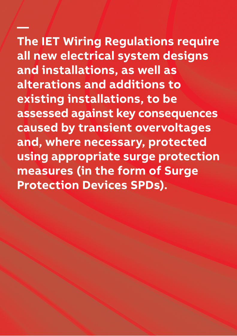
Readers of this guide should be mindful of the need to protect all incoming metallic service lines against the risk of transient overvoltages.BS 7671 provides focussed guidance for theassessment and protection of electrical and electronic equipment intended to be installed on AC mains power supplies. In order to observe the Ligntning Protection Zone LPZ concept within BS 7671 and BS EN 62305, all other incoming metallic service lines, such as data, signal and telecommunications lines, are also a potential route through which transient overvoltages to damage equipment. As such all such lines will require appropriate SPDs.
BS 7671 clearly points the reader back to BS EN 62305 and BS EN 61643 for specific guidance. This is covered extensively in the Furse guide to BS EN 62305 Protection Against Lightning.
IMPORTANT:Equipment is ONLY protected against transient overvoltages if all incoming / outgoing mains and data lines have protection fitted.
Data/Telecom
Power
Data/Telecom
Power
*A safety service, as defined by BS 7671 Part 2, is an electrical system for electrical equipment provided to protect or warn persons in the event of a hazard, or essential to their evacuation from a location.
4 I E T W I R I N G R EG U L ATI O N S B S 76 7 1 1 8TH ED IT I O N
—Transient overvoltage protection Safeguarding your electrical systems
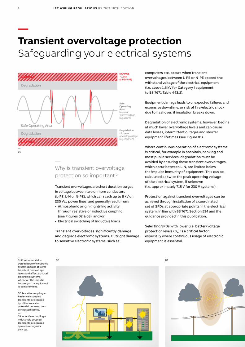
—Why is transient overvoltage protection so important?
Transient overvoltages are short duration surges in voltage between two or more conductors (L-PE, L-N or N-PE), which can reach up to 6 kV on 230 Vac power lines, and generally result from:• Atmospheric origin (lightning activity
through resistive or inductive coupling (see Figures 02 & 03), and/or
• Electrical switching of inductive loads
Transient overvoltages significantly damage and degrade electronic systems. Outright damageto sensitive electronic systems, such as
computers etc, occurs when transient overvoltages between L-PE or N-PE exceed the withstand voltage of the electrical equipment (i.e. above 1.5 kV for Category I equipment to BS 7671 Table 443.2).
Equipment damage leads to unexpected failures and expensive downtime, or risk of fire/electric shock due to flashover, if insulation breaks down.
Degradation of electronic systems, however, begins at much lower overvoltage levels and can cause data losses, intermittent outages and shorter equipment lifetimes (see Figure 01).
Where continuous operation of electronic systems is critical, for example in hospitals, banking and most public services, degradation must be avoided by ensuring these transient overvoltages, which occur between L-N, are limited below the impulse immunity of equipment. This can be calculated as twice the peak operating voltage of the electrical system, if unknown (i.e. approximately 715 V for 230 V systems).
Protection against transient overvoltages can be achieved through installation of a coordinated set of SPDs at appropriate points in the electricalsystem, in line with BS 7671 Section 534 and the guidance provided in this publication.
Selecting SPDs with lower (i.e. better) voltage protection levels (UP) is a critical factor, especially where continuous usage of electronic equipment is essential.
—02
—03
DAMAGE> 1.5 kV (L-PE/N-PE)
—01
—01 Equipment risk –Degradation of electronic systems begins at lower transient overvoltage levels and affects critical electronic systems whenever the impulse immunity of the equipment is compromised.—02 Resistive coupling – Resistively coupled transients are caused by differences in potential between two connected earths.—03 Inductive coupling –Inductively coupled transients are caused by electromagnetic pick-up.
Degradation> 2x peakoperating voltage(e.g. 715 V L-N)
DAMAGE
DAMAGE
Degradation
Degradation
Safe Operating Area
SafeOperatingAreaNominalsystem voltage(e.g. 230 V)
5
SPD selectionSPDs should be selected according to the following requirements:• Voltage protection level (UP)• Continuous operating voltage (UC)• Temporary overvoltages (UTOV)• Nominal discharge current (Inspd) and
impulse current (Iimp)• Prospective fault current and the follow current
interrupt rating
The most important aspect in SPD selection is its voltage protection level (UP). The SPD’s voltage protection level (UP) must be lower than the rated impulse voltage (UW) of protected electrical equipment (defined within Table 443.2), or for continuous operation of critical equipment, its impulse immunity.
Where unknown, impulse immunity can be calculated as twice the peak operating voltage of the electrical system (i.e. approximately 715 V for 230 V systems). Non-critical equipment connected to a 230/400 V fixed electrical installation (e.g. a UPS system) would require protection by an SPD with a UP lower than Category II rated impulse voltage (2.5 kV). Sensitive equipment, such as laptops and PCs, would require additional SPD protection to Category I rated impulse voltage (1.5 kV).
These figures should be considered as achieving a minimal level of protection. SPDs with lower voltage protection levels (UP) offer much better protection, by:• Reducing risk from additive inductive voltages
on the SPD’s connecting leads• Reducing risk from voltage oscillations
downstream which could reach up to twice the SPD’s UP at the equipment terminals
• Keeping equipment stress to a minimum, as well as improving operating lifetime
In essence, an enhanced SPD (SPD* to BS EN 62305)would best meet the selection criteria, as such SPDs offer voltage protection levels (UP) considerably lower than equipment's damage thresholds and thereby are more effective in achieving a protective state.
As per BS EN 62305, all SPDs installed to meet the requirements of BS 7671 shall conform to theproduct and testing standards (BS EN 61643 series).
Selection of SPDs to BS 7671The scope of Section 534 of BS 7671 is to achieve overvoltage limitation within AC power systems to obtain insulation co-ordination, in line with Section 443, and other standards, including BS EN 62305-4.
Overvoltage limitiation is achieved through installation of SPDs as per the recommendations in Section 534 (for AC power systems), and BS EN 62305-4 (for other power and data, signal or telecommunications lines).
Selection of SPDs should achieve the limitation of transient overvoltages of atmospheric origin, and protection against transient overvoltages caused by direct lightning strikes or lightning strikes in the vicinity of a building protected by a structural Lightning Protection System LPS.
—Transient overvoltage protectionSelection of SPDs to BS 7671
5TR A NSI ENT OV ER VO LTAG E PR OTEC TI O N - SEC TI O N O F SPDS TO B S 76 7 1
6
—04
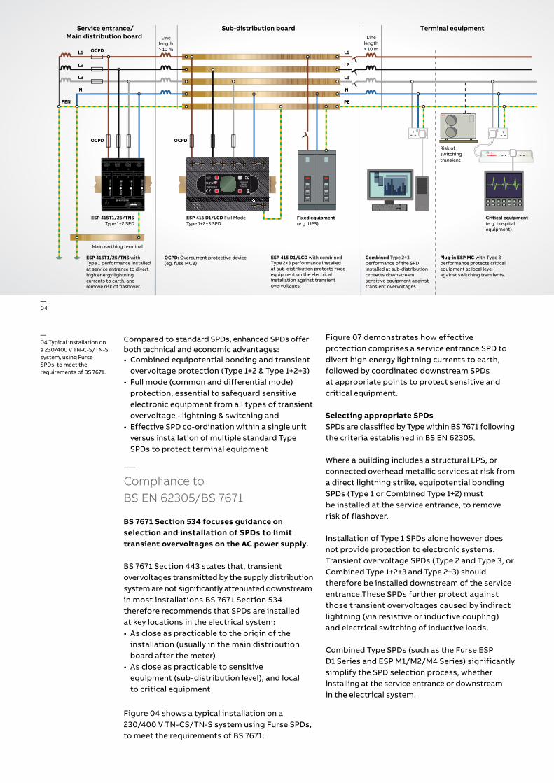
—04 Typical installation on a 230/400 V TN-C-S/TN-S system, using FurseSPDs, to meet the requirements of BS 7671.
Figure 07 demonstrates how effective protection comprises a service entrance SPD to divert high energy lightning currents to earth, followed by coordinated downstream SPDs at appropriate points to protect sensitive and critical equipment.
Selecting appropriate SPDsSPDs are classified by Type within BS 7671 following the criteria established in BS EN 62305.
Where a building includes a structural LPS, or connected overhead metallic services at risk from a direct lightning strike, equipotential bonding SPDs (Type 1 or Combined Type 1+2) mustbe installed at the service entrance, to remove risk of flashover.
Installation of Type 1 SPDs alone however does not provide protection to electronic systems. Transient overvoltage SPDs (Type 2 and Type 3, or Combined Type 1+2+3 and Type 2+3) should therefore be installed downstream of the serviceentrance.These SPDs further protect against those transient overvoltages caused by indirect lightning (via resistive or inductive coupling) and electrical switching of inductive loads.
Combined Type SPDs (such as the Furse ESP D1 Series and ESP M1/M2/M4 Series) significantly simplify the SPD selection process, whether installing at the service entrance or downstream in the electrical system.
Compared to standard SPDs, enhanced SPDs offer both technical and economic advantages:• Combined equipotential bonding and transient
overvoltage protection (Type 1+2 & Type 1+2+3)• Full mode (common and differential mode)
protection, essential to safeguard sensitive electronic equipment from all types of transient overvoltage - lightning & switching and
• Effective SPD co-ordination within a single unit versus installation of multiple standard Type SPDs to protect terminal equipment
—Compliance to BS EN 62305/BS 7671
BS 7671 Section 534 focuses guidance on selection and installation of SPDs to limittransient overvoltages on the AC power supply.
BS 7671 Section 443 states that‚ transient overvoltages transmitted by the supply distribution system are not significantly attenuated downstream in most installations BS 7671 Section 534 therefore recommends that SPDs are installed at key locations in the electrical system:• As close as practicable to the origin of the
installation (usually in the main distribution board after the meter)
• As close as practicable to sensitive equipment (sub-distribution level), and local to critical equipment
Figure 04 shows a typical installation on a 230/400 V TN-CS/TN-S system using Furse SPDs, to meet the requirements of BS 7671.
PE
EnhancedMains
ProtectorEN/IEC 61643
PATENTAPPLIED
FOR
L L' L2 L2' L3 L3' N N'
1114 12
STATUSPE
OCPD
OCPD
OCPD: Overcurrent protective device (eg. fuse MCB)
ESP 415 D1/LCD with combined Type 2+3 performance installedat sub-distribution protects fixed equipment on the electrical installation against transientovervoltages.
Combined Type 2+3performance of the SPDinstalled at sub-distributionprotects downstreamsensitive equipment againsttransient overvoltages.
Plug-in ESP MC with Type 3 performance protects criticalequipment at local levelagainst switching transients.
Linelength> 10 m
Service entrance/Main distribution board
Fixed equipment (e.g. UPS)
Critical equipment (e.g. hospitalequipment)
Risk ofswitchingtransient
ESP 415 D1/LCD Full ModeType 1+2+3 SPD
Sub-distribution board Terminal equipmentLine
length> 10 m
L1
L2
L3
N
L1
L2
L3
N
PEPEN
ESP 415/I/TNS
L1 N
Enhanced Mains Protector
250 AgLIf RED replace
limp = 25kA/modelmax = 100kA/mode
ln = 25kA/modeUc = 320VACUp < 1.4kV
Ures(limp) < 1.3kV
L2 L3
OCPD
Main earthing terminal
ESP 415T1/25/TNS with Type 1 performance installedat service entrance to diverthigh energy lightningcurrents to earth, and remove risk of flashover.
ESP 415T1/25/TNSType 1+2 SPD
7
— Protection for data signal and telecoms applications
—ABB Furse ESP range of SPDsEnhanced solutions to BS EN 62305/BS 7671
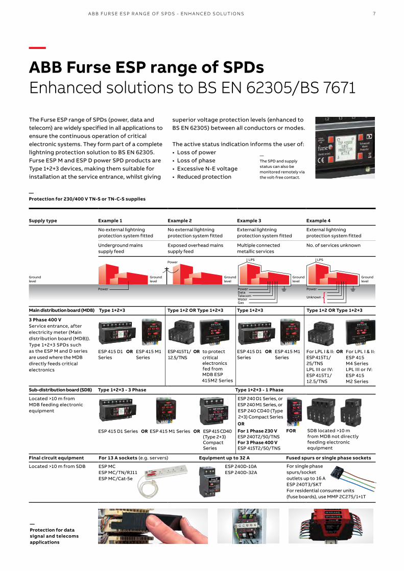
The Furse ESP range of SPDs (power, data and telecom) are widely specified in all applications to ensure the continuous operation of critical electronic systems. They form part of a completelightning protection solution to BS EN 62305.Furse ESP M and ESP D power SPD products are Type 1+2+3 devices, making them suitable for installation at the service entrance, whilst giving
superior voltage protection levels (enhanced to BS EN 62305) between all conductors or modes.
The active status indication informs the user of:• Loss of power • Loss of phase• Excessive N-E voltage • Reduced protection
—The SPD and supply status can also be monitored remotely via the volt-free contact.
A B B FU R SE E SP R A N G E O F SPDS - EN H A N CED SO LU TI O NS
Supply type Example 1 Example 2 Example 3 Example 4
No external lightning protection system fitted
No external lightning protection system fitted
External lightning protection system fitted
External lightning protection system fitted
Underground mainssupply feed
Exposed overhead mainssupply feed
Multiple connectedmetallic services
No. of services unknown
3 Phase 400 VService entrance, afterelectricity meter (Maindistribution board (MDB)).Type 1+2+3 SPDs such as the ESP M and D series are used where the MDB directly feeds critical electronics
ESP 415 D1 OR ESP 415 M1Series Series
ESP 415T1/ OR to protect12.5/TNS critical electronics fed from MDB ESP 415M2 Series
ESP 415 D1 OR ESP 415 M1Series Series
For LPL I & II: ORESP 415T1/25/TNS LPL III or IV:ESP 415T1/12.5/TNS
Sub-distribution board (SDB) Type 1+2+3 - 3 Phase Type 1+2+3 - 1 Phase
Located >10 m fromMDB feeding electronicequipment
ESP 240 D1 Series, or ESP 240 M1 Series, or ESP 240 CD40 (Type 2+3) Compact Series
Final circuit equipment For 13 A sockets (e.g. servers) Equipment up to 32 A Fused spurs or single phase sockets
Located >10 m from SDB
— Protection for 230/400 V TN-S or TN-C-S supplies
LPS LPS
Groundlevel
Groundlevel
Power Unknown
PowerData TelecomWaterGas
Groundlevel
Groundlevel
Power
Power
Groundlevel
Main distribution board (MDB) Type 1+2+3 Type 1+2 OR Type 1+2+3 Type 1+2+3 Type 1+2 OR Type 1+2+3
ESP MCESP MC/TN/RJ11ESP MC/Cat-5e
ESP 240D-10AESP 240D-32A
For LPL I & II: ESP 415 M4 SeriesLPL III or IV:ESP 415 M2 Series
ESP 415 D1 Series OR ESP 415 M1 Series OR ESP 415 CD40 (Type 2+3) Compact Series
OR For 1 Phase 230 V ESP 240T2/50/TNSFor 3 Phase 400 V ESP 415T2/50/TNS
For single phase spurs/socket outlets up to 16 AESP 240T3/SKTFor residential consumer units (fuse boards), use MMP 2C275/1+1T
SDB located >10 m from MDB not directly feeding electronic equipment
FOR
8 I E T W I R I N G R EG U L ATI O N S B S 76 7 1 1 8TH ED IT I O N
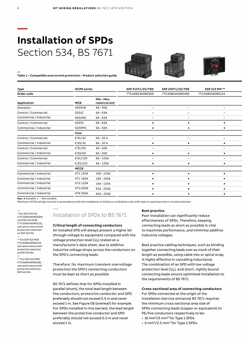
—Installation of SPDs Section 534, BS 7671
Type OCPD series ESP 415T1/25/TNS ESP 240T1/25/TNS ESP 415 M4*** ESP 415 M2** ESP 415 M1* ESP 415 D1/LCD ESP 415T2/50/TNS ESP 240T2/50/TNS MMP 2C275/1+1T
Order code 7TCA085460R0369 7TCA085400R0499 7TCA085460R0124 7TCA085460R0119 7TCA085460R0112 7TCA085460R0105 7TCA085460R0391 7TCA085400R0388 7TCA085460R0185
Application MCBMin - Max. rated current
Domestic SH201B 6A - 40A – – – – – – – – l
Control / Commercial S201C 6A - 63A – – – – – – – – l
Commercial / Industrial S201MC 6A - 63A – – – – – – – – l
Control / Commercial S203C 6A - 63A l l l l l l l l –
Commercial / Industrial S203MC 6A - 63A l l l l l l l l –
Fuse
Control / Commercial E 91/32 6A - 32 A – – – – – – – – l
Commercial / Industrial E 93/32 6A - 32 A l l l l l l l l –
Control / Commercial E 91/50 6A - 50A – – – – – – – – l
Commercial / Industrial E 93/50 6A - 50A l l l l l l l l –
Control / Commercial E 91/125 6A - 125A – – – – – – – – l
Commercial / Industrial E 93/125 6A - 125A l l l l l l l l –
MCCB
Commercial / Industrial XT1 125A 16A - 125A l l l l l l l l –
Commercial / Industrial XT1 160A 16A - 160A l l l l – – l l –
Commercial / Industrial XT2 125A 16A - 125A l l l l l l l l –
Commercial / Industrial XT3 250A 63A - 250A l l l l – – l l –
Commercial / Industrial XT4 250A 63A - 250A l l l l – – l l –
Key: l Suitable / – Not suitable. Maximum OCPD ratings must be in accoradance with the installation to follow co-ordination rules with main or upstream short-circuit protection.
—Table 1 – Compatible overcurrent protection – Product selection guide
Best practicePoor installation can significantly reduce effectiveness of SPDs. Therefore, keeping connecting leads as short as possible is vitalto maximise performance, and minimise additive inductive voltages.
Best practice cabling techniques, such as binding together connecting leads over as much of their length as possible, using cable ties or spiral wrap, is highly effective in cancelling inductance.The combination of an SPD with low voltage protection level (UP), and short, tightly bound connecting leads ensure optimised installation to the requirements of BS 7671.
Cross-sectional area of connecting conductorsFor SPDs connected at the origin of the installation (service entrance) BS 7671 requires the minimum cross-sectional area size of SPDs connecting leads (copper or equivalent) to PE/live conductors respectively to be:• 16 mm²/6 mm² for Type 1 SPDs• 6 mm²/2.5 mm² for Type 2 SPDs
—Installation of SPDs to BS 7671
Critical length of connecting conductorsAn installed SPD will always present a higher let through voltage to equipment compared with the voltage protection level (UP) stated on a manufacturer’s data sheet, due to additive inductive voltage drops across the conductors on the SPD’s connecting leads.
Therefore, for maximum transient overvoltage protection the SPD's connecting conductors must be kept as short as possible.
BS 7671 defines that for SPDs installed inparallel (shunt), the total lead length between line conductors, protective conductor and SPD preferably should not exceed 0.5 m and never exceed 1 m. See Figure 08 (overleaf) for example.For SPDs installed in-line (series), the lead length between the protective conductor and SPD preferably should not exceed 0.5 m and never exceed 1 m.
—* For ESP 240 M1 (7TCA085460R0089) and ESP 415 M1R (7TCA085460R0115), use same overcurrent protection selection as ESP 415 M1.—** For ESP 415 M2R(7TCA085460R0123)use same overcurrentprotection selectionas ESP 415 M2 .—***For ESP 415 M4R(7TCA085460R0126)use same overcurrentprotection selectionESP 415 M4.
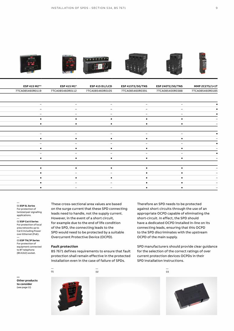
9I NS TA L L ATI O N O F SPDS - SEC TI O N 5 3 4 , B S 76 7 1
Type OCPD series ESP 415T1/25/TNS ESP 240T1/25/TNS ESP 415 M4*** ESP 415 M2** ESP 415 M1* ESP 415 D1/LCD ESP 415T2/50/TNS ESP 240T2/50/TNS MMP 2C275/1+1T
Order code 7TCA085460R0369 7TCA085400R0499 7TCA085460R0124 7TCA085460R0119 7TCA085460R0112 7TCA085460R0105 7TCA085460R0391 7TCA085400R0388 7TCA085460R0185
Application MCBMin - Max. rated current
Domestic SH201B 6A - 40A – – – – – – – – l
Control / Commercial S201C 6A - 63A – – – – – – – – l
Commercial / Industrial S201MC 6A - 63A – – – – – – – – l
Control / Commercial S203C 6A - 63A l l l l l l l l –
Commercial / Industrial S203MC 6A - 63A l l l l l l l l –
Fuse
Control / Commercial E 91/32 6A - 32 A – – – – – – – – l
Commercial / Industrial E 93/32 6A - 32 A l l l l l l l l –
Control / Commercial E 91/50 6A - 50A – – – – – – – – l
Commercial / Industrial E 93/50 6A - 50A l l l l l l l l –
Control / Commercial E 91/125 6A - 125A – – – – – – – – l
Commercial / Industrial E 93/125 6A - 125A l l l l l l l l –
MCCB
Commercial / Industrial XT1 125A 16A - 125A l l l l l l l l –
Commercial / Industrial XT1 160A 16A - 160A l l l l – – l l –
Commercial / Industrial XT2 125A 16A - 125A l l l l l l l l –
Commercial / Industrial XT3 250A 63A - 250A l l l l – – l l –
Commercial / Industrial XT4 250A 63A - 250A l l l l – – l l –
Key: l Suitable / – Not suitable. Maximum OCPD ratings must be in accoradance with the installation to follow co-ordination rules with main or upstream short-circuit protection.
Therefore an SPD needs to be protected against short circuits through the use of an appropriate OCPD capable of eliminating the short-circuit. In effect, the SPD should have a dedicated OCPD installed in-line on its connecting leads, ensuring that this OCPD to the SPD discriminates with the upstream OCPD of the main supply.
SPD manufacturers should provide clear guidance for the selection of the correct ratings of over current protection devices OCPDs in their SPD installation instructions.
These cross-sectional area values are based on the surge current that these SPD connecting leads need to handle, not the supply current.However, in the event of a short circuit, for example due to the end of life condition of the SPD, the connecting leads to the SPD would need to be protected by a suitable Overcurrent Protective Device (OCPD).
Fault protectionBS 7671 defines requirements to ensure that fault protection shall remain effective in the protected installation even in the case of failure of SPDs.
— Other products to consider(see page 11)
—01
—02
—03
—01 ESP SL SeriesFor protection of twisted pair signalling applications.—02 ESP Cat 6 SeriesFor protection of local area networks up toCat 6 including Power over Ethernet (PoE).—03 ESP TN/JP SeriesFor protection of equipment connectedto BT telephone (BS 6312) socket.
10 I E T W I R I N G R EG U L ATI O N S B S 76 7 1 1 8TH ED IT I O N
L N
T2 C
T1 Iimp 4kAIn 20kAImax
oc
40kAU 6kV
c zacU 280V 47-63H
B
DT3
125 AgL
!
GREEN FULL PROTECTIONGREEN & RED REDUCED
PROTECTION(replace unit)
RED NO PROTECTION
WARNING: If lit / flashing disconnectunit & check Neutralto Earth voltage
EN/IEC 61643
PATENTAPPLIED
FOR STATUS INDICATIONESP 240D1
L L1 N1N
1114 12
STATUSSTATT TUSAA
OCPD
OCPD
SPD
< 0.25 m
< 0.25 mMain earthingterminal orconnectingconductor bar
Multiple terminalequipment protectedby SPD at sub-distribution
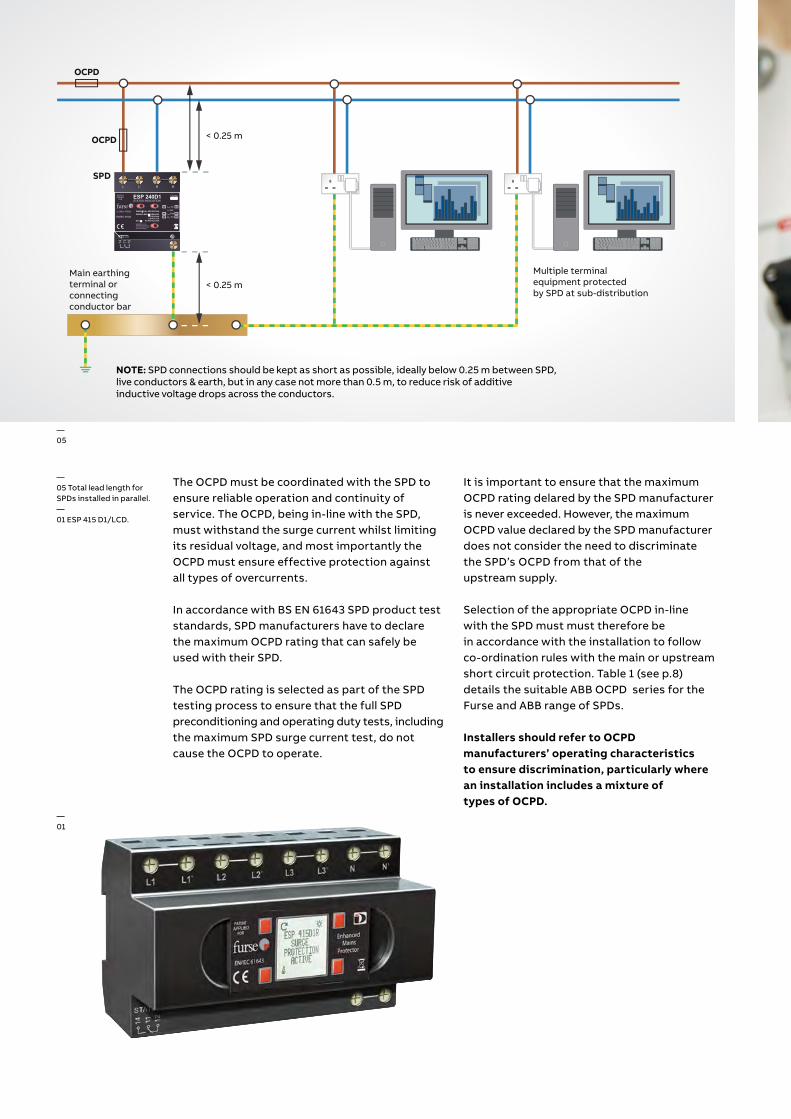
—05
NOTE: SPD connections should be kept as short as possible, ideally below 0.25 m between SPD, live conductors & earth, but in any case not more than 0.5 m, to reduce risk of additive inductive voltage drops across the conductors.
—05 Total lead length for SPDs installed in parallel.—01 ESP 415 D1/LCD.
It is important to ensure that the maximum OCPD rating delared by the SPD manufacturer is never exceeded. However, the maximum OCPD value declared by the SPD manufacturer does not consider the need to discriminate the SPD’s OCPD from that of the upstream supply.
Selection of the appropriate OCPD in-line with the SPD must must therefore be in accordance with the installation to follow co-ordination rules with the main or upstream short circuit protection. Table 1 (see p.8) details the suitable ABB OCPD series for the Furse and ABB range of SPDs.
Installers should refer to OCPD manufacturers’ operating characteristics to ensure discrimination, particularly where an installation includes a mixture of types of OCPD.
The OCPD must be coordinated with the SPD to ensure reliable operation and continuity of service. The OCPD, being in-line with the SPD, must withstand the surge current whilst limiting its residual voltage, and most importantly the OCPD must ensure effective protection against all types of overcurrents.
In accordance with BS EN 61643 SPD product test standards, SPD manufacturers have to declare the maximum OCPD rating that can safely be used with their SPD.
The OCPD rating is selected as part of the SPD testing process to ensure that the full SPD preconditioning and operating duty tests, including the maximum SPD surge current test, do not cause the OCPD to operate.
—01
11
Product range Description Features
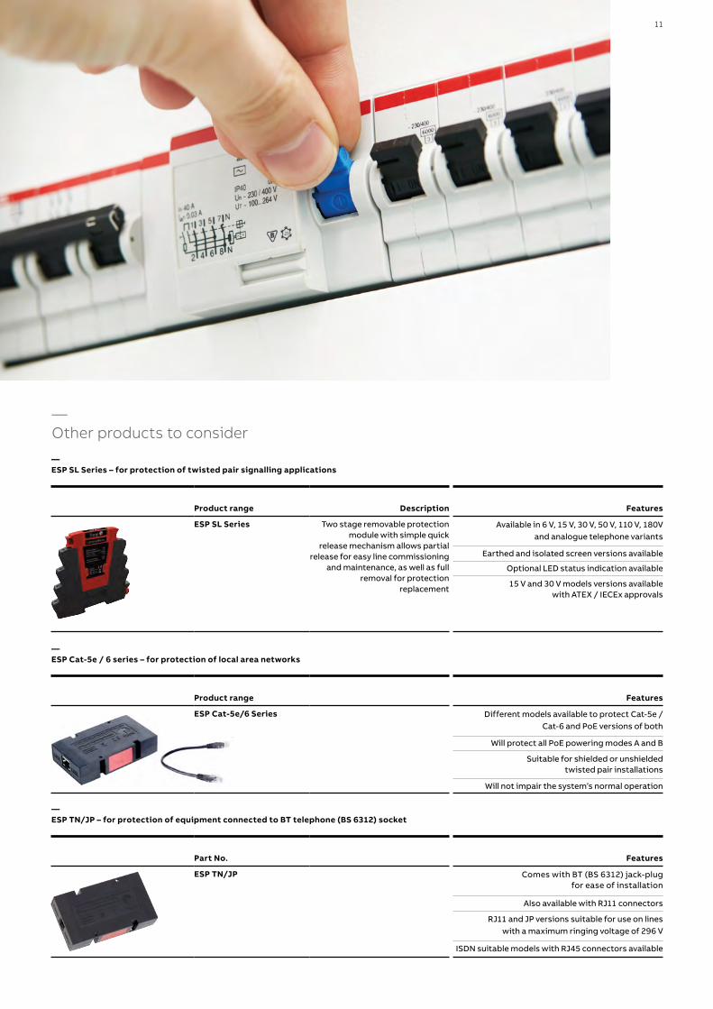
ESP SL Series Two stage removable protection module with simple quick
release mechanism allows partial release for easy line commissioning
and maintenance, as well as full removal for protection
replacement
Available in 6 V, 15 V, 30 V, 50 V, 110 V, 180V and analogue telephone variants
Earthed and isolated screen versions available
Optional LED status indication available
15 V and 30 V models versions available with ATEX / IECEx approvals
— ESP SL Series – for protection of twisted pair signalling applications
Product range Features
ESP Cat-5e/6 Series Different models available to protect Cat-5e / Cat-6 and PoE versions of both
Will protect all PoE powering modes A and B
Suitable for shielded or unshielded twisted pair installations
Will not impair the system’s normal operation
— ESP Cat-5e / 6 series – for protection of local area networks
Part No. Features
ESP TN/JP Comes with BT (BS 6312) jack-plug for ease of installation
Also available with RJ11 connectors
RJ11 and JP versions suitable for use on lines with a maximum ringing voltage of 296 V
ISDN suitable models with RJ45 connectors available
— ESP TN/JP – for protection of equipment connected to BT telephone (BS 6312) socket
—Other products to consider

© Copyright 2022 ABB. All rights reserved. Specifications subject to change without notice.
—ABB FurseWilford RoadNottingham, UKNG2 1EBTel: +44 (0) 115 964 3700E-Mail: [email protected]
www.furse.com
9AK
K10
704
6A75
79 0
4.2
022
Related Documents