- Geometry In H Geomet r y In H Geomet r y In H Geomet r y In H Geomet r y In H This chapter has been reviewed and has additional mat e This chapter has been reviewed and has additional mat e Matthias Goelke. Matthias Goelke. HyperMesh Geometr y T erminology HyperMesh Geometr y T erminology hile dealing with geometry it is important t o be familiar w hile dealing with geometry it is important t o be familiar w y our CAE project typically starts with the import of given y our CAE project typically starts with the import of given STEP , UG, IGES, SolidWorks, solidThinking etc. (of course STEP , UG, IGES, SolidWorks, solidThinking etc. (of course While the importation of data generally occurs with little error , the While the importation of data generally occurs with little error , the wide variety of t ools t o remedy these geometric issues (this is one wide variety of t ools t o remedy these geometric issues (this is one Some of the issues described below do exist because when des Some of the issues described below do exist because when des those of analysts trying t o use the data. For a designer , a single sm those of analysts trying t o use the data. For a designer , a single sm Some resulting geometry issues: Some resulting geometry issues: • Surfaces are not stitched t ogether (i.e. there is a gap b • Surfaces are not stitched t ogether (i.e. there is a gap b • Very small surfaces are squeezed between regular sur • Very small surfaces are squeezed between regular sur • The juncture between two surfaces oft en contains gap 1 1 HyperMesh - HyperMesh HyperMesh HyperMesh HyperMesh erial included by Rahul Ponginan, Prakash Pagadala and erial included by Rahul Ponginan, Prakash Pagadala and with the relevant HyperMesh t erminology: with the relevant HyperMesh t erminology: CAD data e.g. Catia, CAD data e.g. Catia, e, y ou ma y create y our CAD model in HyperMesh as well). e, y ou ma y create y our CAD model in HyperMesh as well). here are issues that can occur , and as such, HyperMesh off ers a here are issues that can occur , and as such, HyperMesh off ers a of the many reasons why HyperMesh is used in so many places). of the many reasons why HyperMesh is used in so many places). signers create CAD geometry , their priorities are diff erent from signers create CAD geometry , their priorities are diff erent from mooth surface is typically split into smaller patches. mooth surface is typically split into smaller patches. between surfaces) between surfaces) rfaces rfaces ps, overlaps, or other misalignments

Welcome message from author
This document is posted to help you gain knowledge. Please leave a comment to let me know what you think about it! Share it to your friends and learn new things together.
Transcript

- Geometry In HyperMesh - Geometry In HyperMesh
Geometry In HyperMeshGeometry In HyperMeshGeometry In HyperMeshGeometry In HyperMesh
This chapter has been reviewed and has additional material This chapter has been reviewed and has additional material
Matthias Goelke.Matthias Goelke.
HyperMesh Geometry TerminologyHyperMesh Geometry TerminologyHyperMesh Geometry Terminology
hile dealing with geometry it is important to be familiar withhile dealing with geometry it is important to be familiar with
your CAE project typically starts with the import of given your CAE project typically starts with the import of given
STEP, UG, IGES, SolidWorks, solidThinking etc. (of course, STEP, UG, IGES, SolidWorks, solidThinking etc. (of course,
While the importation of data generally occurs with little error, thereWhile the importation of data generally occurs with little error, there
wide variety of tools to remedy these geometric issues (this is onewide variety of tools to remedy these geometric issues (this is one
Some of the issues described below do exist because when designeSome of the issues described below do exist because when designe
those of analysts trying to use the data. For a designer, a single smothose of analysts trying to use the data. For a designer, a single smo
Some resulting geometry issues:Some resulting geometry issues:
• Surfaces are not stitched together (i.e. there is a gap b• Surfaces are not stitched together (i.e. there is a gap b
• Very small surfaces are squeezed between regular sur• Very small surfaces are squeezed between regular sur
• The juncture between two surfaces often contains gaps, • The juncture between two surfaces often contains gaps,
11
HyperMesh -HyperMesh -
HyperMeshHyperMeshHyperMeshHyperMesh
erial included by Rahul Ponginan, Prakash Pagadala anderial included by Rahul Ponginan, Prakash Pagadala and
with the relevant HyperMesh terminology:with the relevant HyperMesh terminology:
en CAD data e.g. Catia,en CAD data e.g. Catia,
rse, you may create your CAD model in HyperMesh as well).rse, you may create your CAD model in HyperMesh as well).
there are issues that can occur, and as such, HyperMesh offers athere are issues that can occur, and as such, HyperMesh offers a
of the many reasons why HyperMesh is used in so many places).of the many reasons why HyperMesh is used in so many places).
designers create CAD geometry, their priorities are different fromdesigners create CAD geometry, their priorities are different from
smooth surface is typically split into smaller patches.smooth surface is typically split into smaller patches.
between surfaces)between surfaces)
rfacesrfaces
en contains gaps, overlaps, or other misalignmentsen contains gaps, overlaps, or other misalignments

- Geometry In HyperMesh - Geometry In HyperMesh
Left: CAD with “jumps” results in irregularly shaped elements (middle). Left: CAD with “jumps” results in irregularly shaped elements (middle).
• The geometry is a thin-walled volume structure, i.e. • The geometry is a thin-walled volume structure, i.e.
corresponding mid-surface model meshed with 2D elements corresponding mid-surface model meshed with 2D elements
Original thin walled Original thin walled
Midsurface representation of
• Surfaces penetrate each other (such as at a t-connection) but • Surfaces penetrate each other (such as at a t-connection) but
Original geomOriginal geom
22
HyperMesh -HyperMesh -
elements (middle). Right: improved CAD with regular meshelements (middle). Right: improved CAD with regular mesh
i.e. instead of building a complex an exhaustive 3D mesh, ai.e. instead of building a complex an exhaustive 3D mesh, a
elements would be far betterelements would be far better
alled structurealled structure
of the thin walled structure
connection) but don‘t “feel“ each otherconnection) but don‘t “feel“ each other
geometrygeometry

- Geometry In HyperMesh - Geometry In HyperMesh
Geometry fixed so that there Geometry fixed so that there
• Geometry is much too detailed (e.g. tiny fillets which are n• Geometry is much too detailed (e.g. tiny fillets which are n
Original geometry, nOriginal geometry, n
Simplified geometry where small fillSimplified geometry where small fill
• And many others ...• And many others ...
33
HyperMesh -HyperMesh -
there is proper connectivitythere is proper connectivity
are not needed for the analysis)are not needed for the analysis)
note the small filletsnote the small fillets
fillets are replaced by a sharp edgefillets are replaced by a sharp edge

- Geometry In HyperMesh - Geometry In HyperMesh
Geometry CleanupGeometry CleanupGeometry Cleanup
All of the issues defined in the previous section typically demand what All of the issues defined in the previous section typically demand what
Topology Repair: StrategyTopology Repair: Strategy
Below is a general strategy that can be followed to perform the topologyBelow is a general strategy that can be followed to perform the topology
be changed to suit the needs of your model, but it provides a good be changed to suit the needs of your model, but it provides a good
1. Understand the size and scale of the model1. Understand the size and scale of the model
• With models that represent everything from full size ships• With models that represent everything from full size ships
on a computer monitor, it is often difficult to understandon a computer monitor, it is often difficult to understand
overall size of the model and determine a global elementoverall size of the model and determine a global element
2. Set a cleanup tolerance based upon the previously determined global element size.2. Set a cleanup tolerance based upon the previously determined global element size.
• With the element size established, a cleanup tolerance• With the element size established, a cleanup tolerance
size to be closed by the topology functions. This valuesize to be closed by the topology functions. This value
beyond this limit can introduce distortion into the meshbeyond this limit can introduce distortion into the mesh
3. Use topology display tools to determine what needs to be fixed.3. Use topology display tools to determine what needs to be fixed.
selector to By 2D Toposelector to By 2D Topo
• Visualization mode: By Comp (which assigns the color • Visualization mode: By Comp (which assigns the color
• Visualization mode: By 2D Topo• Visualization mode: By 2D Topo
44
HyperMesh -HyperMesh -
what is called Geometry Cleanup.what is called Geometry Cleanup.
opology repair. This is a generalized strategy which may need toopology repair. This is a generalized strategy which may need to
a good starting point to perform the topology repair.a good starting point to perform the topology repair.
ships to microscopic electronic parts all residing in a graphics areaships to microscopic electronic parts all residing in a graphics area
understand the overall scope of the model. It is critical to get an idea of theunderstand the overall scope of the model. It is critical to get an idea of the
element size that will be applied to the eventual mesh.element size that will be applied to the eventual mesh.
ermined global element size.ermined global element size.
olerance can now be set. The cleanup tolerance specifies the largest gapolerance can now be set. The cleanup tolerance specifies the largest gap
value should never exceed 15-20% of the global element size. Valuesvalue should never exceed 15-20% of the global element size. Values
mesh.mesh.
ed. For instance, to display the topology of 2D geometry set theed. For instance, to display the topology of 2D geometry set the
the color of the component)the color of the component)

- Geometry In HyperMesh - Geometry In HyperMesh
• Visualization mode: Mixed which assigns the component color and adds • Visualization mode: Mixed which assigns the component color and adds
4. Find duplicate surfaces and delete them.4. Find duplicate surfaces and delete them.
• To delete duplicate surfaces, from the menu bar select • To delete duplicate surfaces, from the menu bar select
5. Use equivalence to combine as many free edge pairs as possible.5. Use equivalence to combine as many free edge pairs as possible.
• Visually verify no surfaces were collapsed with this function.• Visually verify no surfaces were collapsed with this function.
6. Use toggle to combine any remaining edges.6. Use toggle to combine any remaining edges.
• Use replace if more control is needed.• Use replace if more control is needed.
7. Use filler surface to fill in any missing surfaces.7. Use filler surface to fill in any missing surfaces.
8. The equivalence, toggle, and filler surface can be accessed within 8. The equivalence, toggle, and filler surface can be accessed within
• To access the Quick Edit panel, from the menu bar select • To access the Quick Edit panel, from the menu bar select
Topology Repair: Tools And PanelsTopology Repair: Tools And Panels
The perimeter of a surface is defined by edges. There are four types The perimeter of a surface is defined by edges. There are four types
• Free edges• Free edges
• Shared edges• Shared edges
• Suppressed edges• Suppressed edges
• Non-manifold edges• Non-manifold edges
55
HyperMesh -HyperMesh -
ponent color and adds topology informationponent color and adds topology information
bar select Geometry > Defeature > Duplicates.bar select Geometry > Defeature > Duplicates.
as possible.as possible.
this function.this function.
within the Quick Edit panel.within the Quick Edit panel.
bar select Geometry > Quick Edit.bar select Geometry > Quick Edit.
types of surface edges:types of surface edges:

- Geometry In HyperMesh - Geometry In HyperMesh
Surface edges are different from lines and are sometimes handledSurface edges are different from lines and are sometimes handled
of surface edges constitutes the geometric topology. Below the
topology is described (Note: the shown model is displayed via thetopology is described (Note: the shown model is displayed via the
Free EdgesFree Edges
Afree edge is an edge that is owned by only one surface. Free edgesAfree edge is an edge that is owned by only one surface. Free edges
On a clean 2D model consisting of surfaces, free edges appear onlyOn a clean 2D model consisting of surfaces, free edges appear only
holes.holes.
Note: Free edges that appear between two adjacent suNote: Free edges that appear between two adjacent su
two surfaces. The automesher will leave a gap in the meshtwo surfaces. The automesher will leave a gap in the mesh
Shared EdgesShared Edges
Ashared edge is an edge that is owned, or shared, by two adjacentAshared edge is an edge that is owned, or shared, by two adjacent
When the edge between two surfaces is a shared edge (this is whatWhen the edge between two surfaces is a shared edge (this is what
the two surfaces - they are geometrically continuous. The automesherthe two surfaces - they are geometrically continuous. The automesher
and will produce a continuous mesh without any gaps along thatand will produce a continuous mesh without any gaps along that
that cross over a shared edge.that cross over a shared edge.
Suppressed EdgesSuppressed Edges
A suppressed edge is shared by two surfaces but it is ignored by theA suppressed edge is shared by two surfaces but it is ignored by the
Like a shared edge, a suppressed edge indicates geometric continuityLike a shared edge, a suppressed edge indicates geometric continuity
automesher will mesh across a suppressed edge as if were not eautomesher will mesh across a suppressed edge as if were not e
length of a suppressed edge and, consequently, individual elementslength of a suppressed edge and, consequently, individual elements
effectively combining surfaces into larger logical meshable regionseffectively combining surfaces into larger logical meshable regions
Non-Manifold EdgesNon-Manifold Edges
Anon-manifold edge is owned by three or more surfaces. Non-maniAnon-manifold edge is owned by three or more surfaces. Non-mani
They typically occur at “T” intersections between surfaces or whenThey typically occur at “T” intersections between surfaces or when
places seed nodes along their length and will produce a continuousplaces seed nodes along their length and will produce a continuous
not construct any individual elements that cross over a T-joint edgenot construct any individual elements that cross over a T-joint edge
66
HyperMesh -HyperMesh -
handled differently for certain HyperMesh operations. The connectivityhandled differently for certain HyperMesh operations. The connectivity
the four types of surface edges which represents the geometric
2D Topo mode in HyperMesh).2D Topo mode in HyperMesh).
edges are colored red by default.edges are colored red by default.
only along the outer perimeter of the part and around any interioronly along the outer perimeter of the part and around any interior
surfaces indicate the existence of a gap between thesurfaces indicate the existence of a gap between the
mesh wherever there is a gap between two surfaces.mesh wherever there is a gap between two surfaces.
adjacent surfaces. Shared edges are colored green by default.adjacent surfaces. Shared edges are colored green by default.
what you typically want to have), there is no gap or overlap betweenwhat you typically want to have), there is no gap or overlap between
omesher always places seed nodes along the length a shared edgeomesher always places seed nodes along the length a shared edge
edge. The automesher will not construct any individual elementsedge. The automesher will not construct any individual elements
the automesher. Suppressed edges are colored blue by default.the automesher. Suppressed edges are colored blue by default.
continuity between two surfaces but, unlike a shared edge, thecontinuity between two surfaces but, unlike a shared edge, the
even there. The automesher does not place seed nodes along theeven there. The automesher does not place seed nodes along the
elements will span across it. By suppressing undesirable edges you areelements will span across it. By suppressing undesirable edges you are
regions.regions.
manifold edges are colored yellow by default.manifold edges are colored yellow by default.
when 2 or more duplicate surfaces exist. The automesher alwayswhen 2 or more duplicate surfaces exist. The automesher always
continuous mesh without any gaps along that edge. The automesher willcontinuous mesh without any gaps along that edge. The automesher will
edge. These edges cannot be suppressed.edge. These edges cannot be suppressed.

- Geometry In HyperMesh - Geometry In HyperMesh
SolidsSolids
A solid is a closed volume of surfaces that can take any shape. SolidsA solid is a closed volume of surfaces that can take any shape. Solids
tetra and solid meshing. Its color is determined by the component tetra and solid meshing. Its color is determined by the component
The surfaces defining a solid can belong to multiple componentThe surfaces defining a solid can belong to multiple component
controlled only by the component collector to which the solid belongs.controlled only by the component collector to which the solid belongs.
Below is an image of solid topology as well as a description of the three types Below is an image of solid topology as well as a description of the three types
To activate the 3D topology mode view, please activate the corresponding seTo activate the 3D topology mode view, please activate the corresponding se
77
HyperMesh -HyperMesh -
Solids are three-dimensional entities that can be used in automaticSolids are three-dimensional entities that can be used in automatic
ponent collector to which it belongs.ponent collector to which it belongs.
collectors. The display of a solid and its bounding surfaces arecollectors. The display of a solid and its bounding surfaces are
the solid belongs.the solid belongs.
the three types of surfaces which define the topology of a solid.the three types of surfaces which define the topology of a solid.
e the corresponding settinge the corresponding setting

- Geometry In HyperMesh - Geometry In HyperMesh
Bounding FacesBounding Faces
A bounding face is a surface that defines the outer boundary of a A bounding face is a surface that defines the outer boundary of a
bounding face is unique and is not shared with any other solid. A single bounding face is unique and is not shared with any other solid. A single
Fin FacesFin Faces
A fin face is a surface that has the same solid on all sides i.e. it actsA fin face is a surface that has the same solid on all sides i.e. it acts
default.default.
A fin face can be created when manually merging solids or when creating A fin face can be created when manually merging solids or when creating
Full Partition FacesFull Partition Faces
A full partition face is a surface that defines a shared boundary betA full partition face is a surface that defines a shared boundary bet
by default.by default.
A full partition face can be created when splitting a solid or whenA full partition face can be created when splitting a solid or when
intersecting locations.intersecting locations.
88
HyperMesh -HyperMesh -
a single solid. Bounding faces are shaded green by default. A a single solid. Bounding faces are shaded green by default. A
single solid volume is defined entirely by bounding faces. single solid volume is defined entirely by bounding faces.
acts as a fin inside of a single solid. Fin faces are shaded red byacts as a fin inside of a single solid. Fin faces are shaded red by
when creating solids with internal fin surfaces.when creating solids with internal fin surfaces.
etween one or more solids. Full partition faces are shaded yellowetween one or more solids. Full partition faces are shaded yellow
when using Boolean operations to join multiple solids at shared orwhen using Boolean operations to join multiple solids at shared or

- Geometry In HyperMesh - Geometry In HyperMesh
What You Need To KnWhat You Need To Kn
Green edges - 2 surfaces are stitched together; the FE mesh willGreen edges - 2 surfaces are stitched together; the FE mesh will
green edge.green edge.
Red edges - indicates free surface edges. Red edges inside theRed edges - indicates free surface edges. Red edges inside the
together (gap); the FE mesh will NOT be linked (not compatible).together (gap); the FE mesh will NOT be linked (not compatible).
Yellow edges — minimum of 3 edges are stitched together; the FE mesh willYellow edges — minimum of 3 edges are stitched together; the FE mesh will
Blue edges — Suppressed green edge. Surfaces are “melted“ togBlue edges — Suppressed green edge. Surfaces are “melted“ tog
and elements are placed across it.and elements are placed across it.
How to visualize the edgeHow to visualize the edge
colors?colors?
Display is controlled in the Visualization toolbar by activatingDisplay is controlled in the Visualization toolbar by activating
colored respectively) or Mixed (surfaces are displayed in their originalcolored respectively) or Mixed (surfaces are displayed in their original
Browser), edges are colored respectively.Browser), edges are colored respectively.
Panels to be used:Panels to be used:
• Toggle surfaces (combining, stitching )• Toggle surfaces (combining, stitching )
• Trimming surfaces (splitting)• Trimming surfaces (splitting)
• Suppressing combined edges• Suppressing combined edges
Geometry > Quick Edit opens up a very comprehensive panel whichGeometry > Quick Edit opens up a very comprehensive panel which
above listed tasks.above listed tasks.
The before mentioned panels describe just a very minor fraction of The before mentioned panels describe just a very minor fraction of
you feel more comfortable with the process, you will automatically you feel more comfortable with the process, you will automatically
8080
HyperMesh -HyperMesh -
Know Or RememberKnow Or Remember
will be linked (compatible), its nodes will line up with thewill be linked (compatible), its nodes will line up with the
the geometry tell you that the surfaces are not stitchedthe geometry tell you that the surfaces are not stitched
patible).patible).
ther; the FE mesh will be compatible.ther; the FE mesh will be compatible.
ogether. In other words, the mesher does not see this edgeogether. In other words, the mesher does not see this edge
ating for instance By 2D Topo (surfaces turn into grey, edges areating for instance By 2D Topo (surfaces turn into grey, edges are
original color (reminder: surface color is controlled in the Modeloriginal color (reminder: surface color is controlled in the Model
which allows you (among many other options) to execute thewhich allows you (among many other options) to execute the
of HyperMesh‘s geometry cleanup functionalities. Once of HyperMesh‘s geometry cleanup functionalities. Once
omatically explore and learn more about other techniques.omatically explore and learn more about other techniques.
8080
- Geometry In HyperMesh - Geometry In HyperMesh
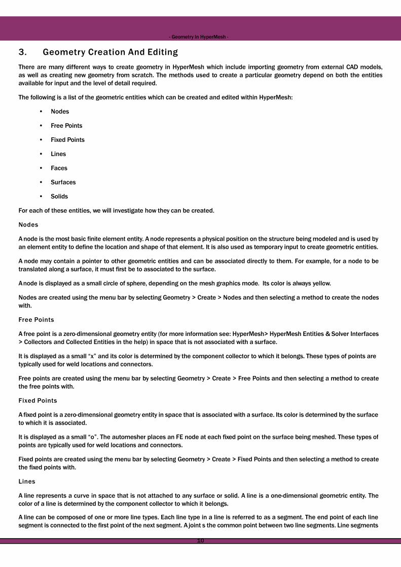
3. Geometry Creation And Editing3. Geometry Creation And Editing3. Geometry Creation And Editing
There are many different ways to create geometry in HyperMeshThere are many different ways to create geometry in HyperMesh
as well as creating new geometry from scratch. The methods usedas well as creating new geometry from scratch. The methods used
available for input and the level of detail required.available for input and the level of detail required.
The following is a list of the geometric entities which can be creatThe following is a list of the geometric entities which can be creat
• Nodes• Nodes
• Free Points• Free Points
• Fixed Points• Fixed Points
• Lines• Lines
• Faces• Faces
• Surfaces• Surfaces
• Solids• Solids
For each of these entities, we will investigate how they can be creaFor each of these entities, we will investigate how they can be crea
NodesNodes
A node is the most basic finite element entity. A node represents aA node is the most basic finite element entity. A node represents a
an element entity to define the location and shape of that element.an element entity to define the location and shape of that element.
A node may contain a pointer to other geometric entities and canA node may contain a pointer to other geometric entities and can
translated along a surface, it must first be to associated to the surtranslated along a surface, it must first be to associated to the sur
Anode is displayed as a small circle of sphere, depending on the meshAnode is displayed as a small circle of sphere, depending on the mesh
Nodes are created using the menu bar by selecting Geometry > CreaNodes are created using the menu bar by selecting Geometry > Crea
with.with.
Free PointsFree Points
A free point is a zero-dimensional geometry entity (for more informationA free point is a zero-dimensional geometry entity (for more information
> Collectors and Collected Entities in the help) in space that is no> Collectors and Collected Entities in the help) in space that is no
It is displayed as a small “x” and its color is determined by the comIt is displayed as a small “x” and its color is determined by the com
typically used for weld locations and connectors.typically used for weld locations and connectors.
Free points are created using the menu bar by selecting GeometrFree points are created using the menu bar by selecting Geometr
the free points with.the free points with.
Fixed PointsFixed Points
A fixed point is a zero-dimensional geometry entity in space that isA fixed point is a zero-dimensional geometry entity in space that is
to which it is associated.to which it is associated.
It is displayed as a small “o”. The automesher places an FE node atIt is displayed as a small “o”. The automesher places an FE node at
points are typically used for weld locations and connectors.points are typically used for weld locations and connectors.
Fixed points are created using the menu bar by selecting GeometrFixed points are created using the menu bar by selecting Geometr
the fixed points with.the fixed points with.
LinesLines
A line represents a curve in space that is not attached to any surA line represents a curve in space that is not attached to any sur
color of a line is determined by the component collector to which itcolor of a line is determined by the component collector to which it
A line can be composed of one or more line types. Each line typeA line can be composed of one or more line types. Each line type
segment is connected to the first point of the next segment. A jointsegment is connected to the first point of the next segment. A joint
1010
HyperMesh -HyperMesh -
HyperMesh which include importing geometry from external CAD models,HyperMesh which include importing geometry from external CAD models,
used to create a particular geometry depend on both the entitiesused to create a particular geometry depend on both the entities
ted and edited within HyperMesh:ted and edited within HyperMesh:
created.created.
a physical position on the structure being modeled and is used bya physical position on the structure being modeled and is used by
element. It is also used as temporary input to create geometric entities.element. It is also used as temporary input to create geometric entities.
can be associated directly to them. For example, for a node to becan be associated directly to them. For example, for a node to be
rface.rface.
mesh graphics mode. Its color is always yellow.mesh graphics mode. Its color is always yellow.
Create > Nodes and then selecting a method to create the nodesCreate > Nodes and then selecting a method to create the nodes
ormation see: HyperMesh> HyperMesh Entities & Solver Interfacesormation see: HyperMesh> HyperMesh Entities & Solver Interfaces
ot associated with a surface.ot associated with a surface.
mponent collector to which it belongs. These types of points aremponent collector to which it belongs. These types of points are
ry > Create > Free Points and then selecting a method to createry > Create > Free Points and then selecting a method to create
associated with a surface. Its color is determined by the surfaceassociated with a surface. Its color is determined by the surface
at each fixed point on the surface being meshed. These types ofat each fixed point on the surface being meshed. These types of
ry > Create > Fixed Points and then selecting a method to createry > Create > Fixed Points and then selecting a method to create
rface or solid. A line is a one-dimensional geometric entity. The rface or solid. A line is a one-dimensional geometric entity. The
it belongs.it belongs.
in a line is referred to as a segment. The end point of each linein a line is referred to as a segment. The end point of each line
joint s the common point between two line segments. Line segmentsjoint s the common point between two line segments. Line segments
1010

- Geometry In HyperMesh - Geometry In HyperMesh
are maintained as a single line entity, so operations performed onare maintained as a single line entity, so operations performed on
automatically uses the appropriate number and type of line segments
It is important to realize that lines are different from surface edgesIt is important to realize that lines are different from surface edges
operations.operations.
Lines are created using the menu bar by selecting Geometry > CreaLines are created using the menu bar by selecting Geometry > Crea
SurfacesSurfaces
A surface represents the geometry associated with a physical paA surface represents the geometry associated with a physical pa
used in automatic mesh generation. Its color is determined by theused in automatic mesh generation. Its color is determined by the
A surface is comprised of one or more faces. Each face contains aA surface is comprised of one or more faces. Each face contains a
When a surface has several faces, HyperMesh maintains all of theWhen a surface has several faces, HyperMesh maintains all of the
surface affect all the faces that comprise the surface. In general,surface affect all the faces that comprise the surface. In general,
type of surface faces to represent the geometry.type of surface faces to represent the geometry.
Surfaces are created using the menu bar by selecting GeometrySurfaces are created using the menu bar by selecting Geometry
surfaces with.surfaces with.
SolidsSolids
A solid is a closed volume of surfaces that can take any shape. SolidsA solid is a closed volume of surfaces that can take any shape. Solids
tetra and solid meshing. Its color is determined by the component tetra and solid meshing. Its color is determined by the component
The surfaces defining a solid can belong to multiple componentThe surfaces defining a solid can belong to multiple component
controlled only by the component collector to which the solid belongs.controlled only by the component collector to which the solid belongs.
Solids are created using the menu bar by selecting Geometry > CreaSolids are created using the menu bar by selecting Geometry > Crea
with.with.Reminder: The newly created geometry will be placedReminder: The newly created geometry will be placed
Check the Model Browser for the current component Check the Model Browser for the current component
1111
HyperMesh -HyperMesh -
on the line affect each segment of the line. In general, HyperMeshon the line affect each segment of the line. In general, HyperMesh
segments to represent the geometry.
dges and are sometimes handled differently for certain HyperMeshdges and are sometimes handled differently for certain HyperMesh
Create > Lines and then selecting a method to create the lines with.Create > Lines and then selecting a method to create the lines with.
part. A surface is a two-dimensional geometric entity that may bepart. A surface is a two-dimensional geometric entity that may be
the component collector to which it belongs.the component collector to which it belongs.
a mathematical surface and edges to trim the surface, if required.a mathematical surface and edges to trim the surface, if required.
the faces as a single surface entity. Operations performed on thethe faces as a single surface entity. Operations performed on the
general, HyperMesh automatically uses the appropriate number of andgeneral, HyperMesh automatically uses the appropriate number of and
y > Create > Surfaces and then selecting a method to create they > Create > Surfaces and then selecting a method to create the
Solids are three-dimensional entities that can be used in automaticSolids are three-dimensional entities that can be used in automatic
ponent collector to which it belongs.ponent collector to which it belongs.
collectors. The display of a solid and its bounding surfaces arecollectors. The display of a solid and its bounding surfaces are
the solid belongs.the solid belongs.
Create > Solids and then selecting a method to create the solids Create > Solids and then selecting a method to create the solids
placed /stored in the currently active component collector.placed /stored in the currently active component collector.
ponent collector.ponent collector.
1111

- Geometry In - Geometry In
8.4 Importing CAD Geometry8.4 Importing CAD Geometry8.4 Importing CAD Geometry
To import geometry, the Import Browser, accessible through the To import geometry, the Import Browser, accessible through the
Using the Import Browser, the user can import data from popularUsing the Import Browser, the user can import data from popular
• Unigraphics• Unigraphics
• Supports import of .prt files• Supports import of .prt files
• Provides a UG part browser• Provides a UG part browser
• Requires an installation of UG to be accessible, • Requires an installation of UG to be accessible,
• CATIA• CATIA
• Supports import of .model (V4) files• Supports import of .model (V4) files
• Additional license from Altair is required of • Additional license from Altair is required of
• Pro/Engineer• Pro/Engineer
• Supports import of .prt and .asm files.• Supports import of .prt and .asm files.
Additionally HyperMesh supports the import of the following intermediaAdditionally HyperMesh supports the import of the following intermedia
• IGES (.igs & .iges)• IGES (.igs & .iges)
• STEP (.stp)• STEP (.stp)
In addition, HyperMesh also supports the following CAD packagesIn addition, HyperMesh also supports the following CAD packages
• ACIS• ACIS
• DXF• DXF
• JT• JT
• Parasolid• Parasolid
• PDGS• PDGS
• VDAFS• VDAFS
Advanced Import OptionsAdvanced Import Options
The cleanup tolerance is used to determine if two surface edgesThe cleanup tolerance is used to determine if two surface edges
cleanup tol toggle controls the following items:cleanup tol toggle controls the following items:
• if two surface edges are close enough to be automatically combined • if two surface edges are close enough to be automatically combined
• if a surface is degenerate and should be removed.• if a surface is degenerate and should be removed.
If you use the automatic cleanup tolerance option, the complexityIf you use the automatic cleanup tolerance option, the complexity
a tolerance to maximize the shared edges (green edges) is selecta tolerance to maximize the shared edges (green edges) is select
what is used internally by the translator.what is used internally by the translator.
1212
In HyperMesh -In HyperMesh -
the Import Geometry icon , is used.the Import Geometry icon , is used.
CAD packages such asCAD packages such as
accessible, either locally or on a networkaccessible, either locally or on a network
of .catpart (V5) file import.of .catpart (V5) file import.
ermediate translational languages:ermediate translational languages:
ages for Geometry Import:ages for Geometry Import:
edges are the same and if two surface vertices are the same. The edges are the same and if two surface vertices are the same. The
omatically combined into a shared edge (green edges)omatically combined into a shared edge (green edges)
xity of the surface and edge geometries are taken into account andxity of the surface and edge geometries are taken into account and
ted. The automatic cleanup tolerance value defaults to 100 timested. The automatic cleanup tolerance value defaults to 100 times
1212
Related Documents