Content 1. ATTENTION....................................................................................................... 1 2. MAIN COMPONENT INTRODUCTION........................................................2 3. SPECIFICATION............................................................................................... 3 4. ACCESSORY AND ASSEMBLYSKETCH MAP......................................... 4 5. MACHINE OPERATION.................................................................................. 5 6. LCD AND CONTROL PANEL......................................................................... 5 7. BLADE................................................................................................................ 6 8. FEEDING THE MATERIAL............................................................................. 7 9. TESTING............................................................................................................ 7 10. TRANSFERRING THE PATTERN...............................................................7 11. TROUBLE SHOOTING................................................................................. 8 ATTACHMENT 1 USB DRIVER INSTALLATION........................................ 10 ATTACHMENT 2 ARTCUT SOFTWARE SETTING....................................11 ATTACHMENT 3 OPERATION OF CORELDRAW PLUG-IN................12 ATTACHMENT 4 FLEXI12 SOFTWARE OPERATION.............................14 ATTACHMENT 5 ANYCUT S OFTWAR E OPERATION ................................... 19

Welcome message from author
This document is posted to help you gain knowledge. Please leave a comment to let me know what you think about it! Share it to your friends and learn new things together.
Transcript
Content1.ATTENTION.......................................................................................................1
2.MAIN COMPONENT INTRODUCTION........................................................2
3.SPECIFICATION...............................................................................................3
4.ACCESSORY AND ASSEMBLYSKETCH MAP.........................................4
5.MACHINE OPERATION..................................................................................5
6.LCD AND CONTROL PANEL.........................................................................5
7.BLADE................................................................................................................6
8.FEEDING THE MATERIAL.............................................................................7
9.TESTING............................................................................................................7
10.TRANSFERRING THE PATTERN...............................................................7
11.TROUBLE SHOOTING................................................................................. 8
ATTACHMENT 1 USB DRIVER INSTALLATION........................................10
ATTACHMENT 2 ARTCUTSOFTWARE SETTING....................................11
ATTACHMENT 3 OPERATION OF CORELDRAW PLUG-IN................12
ATTACHMENT 4 FLEXI12 SOFTWARE OPERATION.............................14
ATTACHMENT 5 ANYCUT SOFTWARE OPERATION................................... 19
1: Attention
1. Remove all the protected material before using the machine.
2. Check the label on the back or side of the machine, make sure the power supply is matching
the machine rated voltage.
3. Connect power plug to the socket when the machine is switched "OFF "
4. Don't touch the power cable with the wet finger to avoid electric shock.
5. Please use the power cable and the data line approval bymanufacturer.
6. Prevent metal matter and liquid drop into the machine.it may causemalfunction.
7.Wait 15 seconds to restart the computer after power brake out to protect themachine.
8. Plug the power off and turn the switch off under thunderstormweather.
9. Don't replace the component personally.
10. Manufacturer have the right to modify the product specification without informing.
11.Manufacturer only undertake the legal obligation to product itself, do not responsibly tothe
loss cause by product failure.
12. Without our approval, any people can’t copy or spread this manual.

2: Main Component Introduction
PEType
Left side Right side
XEType
XLType
1. cover 6. LCD
2. Pinch roller 7. Right cover
3. Metal roller 8. Control panel
4. carriage 9.blade holder
5. Reset switch 10. Left cover
11. Power cable
12. fuse 14.USB port13.power supply 15.serial port
Left side Right side
1. cover 6.control panel
2. Pinch roller 7. Right cover
3. Metal roller 8.reset switch
4. carriage 9.blade holder
5. LCD 10. Left cover
11.power cable
12. fuse 14.USB port13.power supply 15.serial port
Left side Right side
1. cover 6.control panel
2. Pinch roller 7. Right cover
3. Metal roller 8. blade holder
4. carriage 9. Left cover
5. LCD
10.power cable 12.USB port11. power supply 13.serial port
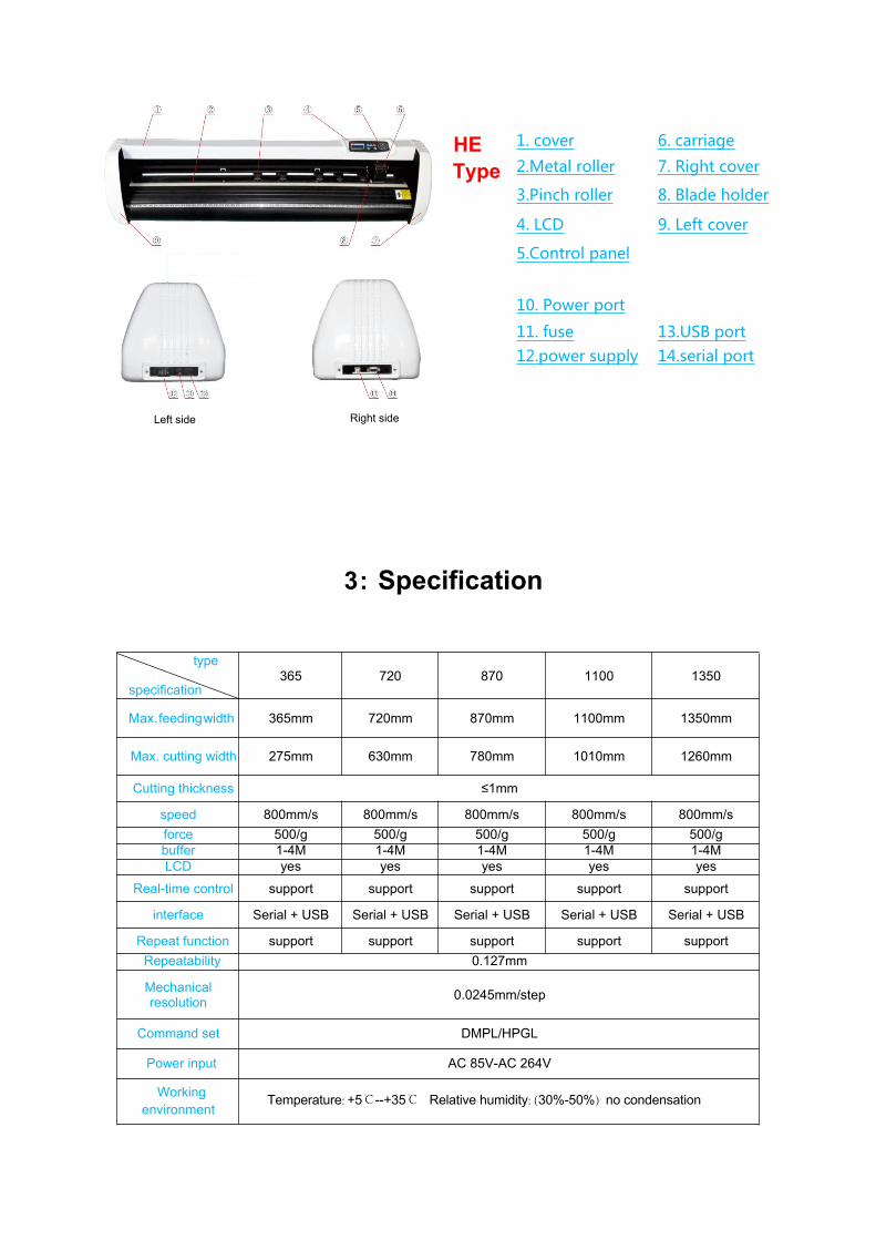
HEType
3: Specification
type
specification365 720 870 1100 1350
Max.feedingwidth 365mm 720mm 870mm 1100mm 1350mm
Max. cutting width 275mm 630mm 780mm 1010mm 1260mm
Cutting thickness ≤1mm
speed 800mm/s 800mm/s 800mm/s 800mm/s 800mm/s
force 500/g 500/g 500/g 500/g 500/gbuffer 1-4M 1-4M 1-4M 1-4M 1-4MLCD yes yes yes yes yes
Real-time control support support support support support
interface Serial + USB Serial + USB Serial + USB Serial + USB Serial + USB
Repeat function support support support support support
Repeatability 0.127mm
Mechanicalresolution
0.0245mm/step
Command set DMPL/HPGL
Power input AC 85V-AC 264V
Workingenvironment
Temperature: +5℃--+35℃ Relative humidity: (30%-50%) no condensation
Left side Right side
1. cover 6. carriage
2.Metal roller 7. Right cover
3.Pinch roller 8. Blade holder
4. LCD 9. Left cover
5.Control panel
10. Power port
11. fuse 13.USB port12.power supply 14.serial port

Name Quantity Note
1 Power cable 1
2 Blade 1
3 Blade holder 1
4 Pen holder 1
5 pen 1
6 Serial cable 1
7 USB cable 1
8 Allen wrench 1
9 USB driver 1 Manual include
10 Support screw 1 option
11 Dust cover 1 option
4: Accessory and Assembly Sketch Map
Accessory Iron stand sketch map
Aluminum stand sketch map XL stand sketchmap
5: Machine Operation
1 、 Place the machine in a flat surface and connect with a grounded cable. Make sure that is enough room near
the machine.
2 、 Turn on the power , LCD light up, carriage move to the right,metal roller move forward and backward,it
show machine reset complete.
3 、 Blade bracket will lift up after turn on the power. Now press the “origin” key, blade bracket will drop down.
Release that key, it lift again. It show the carriage work well.
4、Press “offline” key,yellow indicator light up, press“◀”or“▶”to move the carriage,press“▼”or“▲”to move
the metal roller;if press “▼”and “▲”at the same time,it will active the self inspection program.
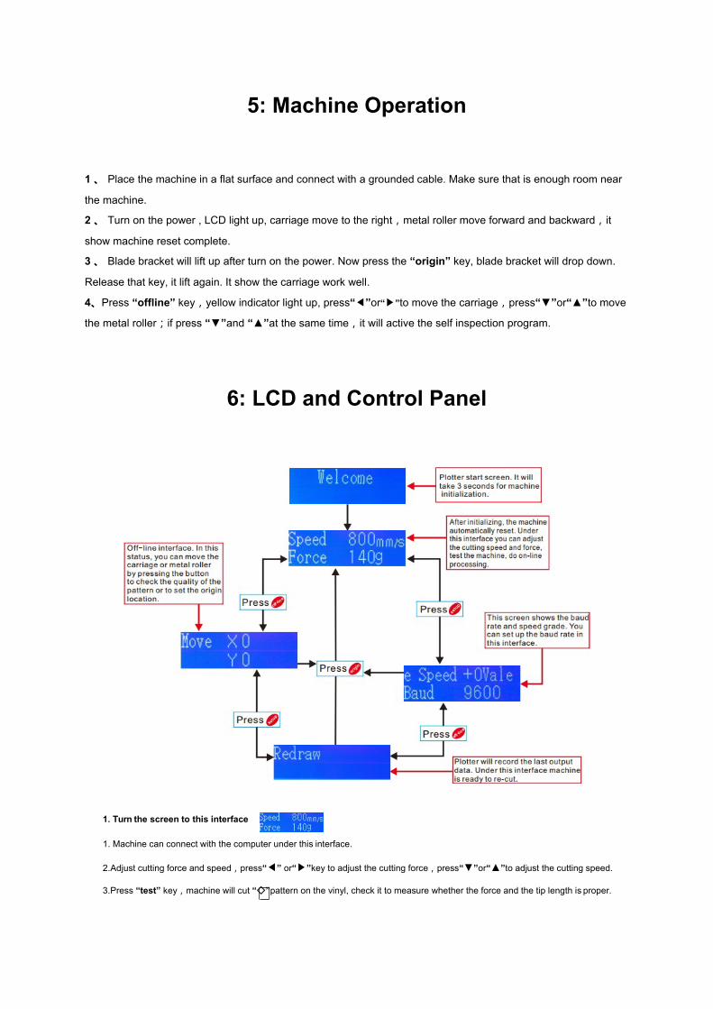
6: LCD and Control Panel
1. Turn the screen to this interface
1. Machine can connect with the computer under this interface.
2.Adjust cutting force and speed,press“◀” or“▶”key to adjust the cutting force,press“▼”or“▲”to adjust the cutting speed.
3.Press “test” key,machine will cut “◇”pattern on the vinyl, check it to measure whether the force and the tip length is proper.
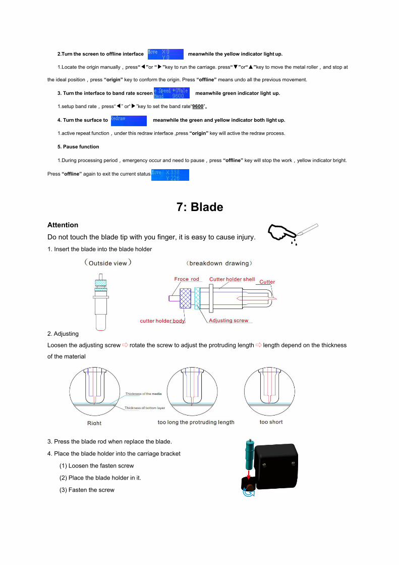
2.Turn the screen to offline interface meanwhile the yellow indicator light up.
1.Locate the origin manually,press“◀”or “▶”key to run the carriage. press“▼”or“▲”key to move the metal roller,and stop at
the ideal position,press “origin” key to conform the origin. Press “offline” means undo all the previous movement.
3. Turn the interface to band rate screen meanwhile green indicator light up.
1.setup band rate,press“◀” or“▶”key to set the band rate“9600”。
4. Turn the surface to meanwhile the green and yellow indicator both light up.
1.active repeat function,under this redraw interface ,press “origin” key will active the redraw process.
5. Pause function
1.During processing period,emergency occur and need to pause,press “offline” key will stop the work,yellow indicator bright.
Press “offline” again to exit the current status.
Attention
7: Blade
Do not touch the blade tip with you finger, it is easy to cause injury.
1. Insert the blade into the blade holder
2. Adjusting
Loosen the adjusting screw⇨ rotate the screw to adjust the protruding length⇨ length depend on the thickness
of the material
3. Press the blade rod when replace the blade.
4. Place the blade holder into the carriage bracket
(1) Loosen the fasten screw
(2) Place the blade holder in it.
(3) Fasten the screw

8: Feeding Material
1、Locating the pinch roller depend on the material
Machine has two or four pinch roller and can be move along the rail. Lift up the handle and move the back of
the pinch roller to the proper place.
(1) Pinch roller must be place in the area with knurling and sand layer
(2) Pinch roller must has 10 to 50mm away from material edge.
2、Feeding material
(1) Lift up the handle.
(2) Feed vinyl, from the middle of the pinch roller wheel and the metal roller
(3) Place the material to position, then press handle down.
(4) Press offline to move the material forward and backward, observe the edge of the material on the
scaleplate. If during the movement material have right-hand deviation, then lift the right pinch roller. Push the
material a little back and then press handle down again. Adjust the material for several times until it is in
position.
9: Testing
1、Testing the machine
Before processing, we should do a “testing” to check the pressure of blade/pen. Press “offline” key(yellow
indicator light up),meanwhile press“▼” and “▲”key,pen/blade will draw/cut a pattern “◇” on the vinyl.
2、Adjusting the pressure
On the LCD, high value means high pressure. Low value means low pressure. Adjust the value according to
the thickness and soft or hard. If too low the pressure is, vinyl will not be cut out. If too high the pressure is, it may
cause pattern deformation or incompletion.
3、Ensure blade bottom always touch with the vinyl surface ,the perfect extended length of tip is 2/3 of
material thickness to avoid cutting off the backing layer.
4、Adopt much lower pressure when using the pen holder.
5、Redo the testing process after starting up or change the material to achieve best cutting force.

10: Transferring The Pattern
Cutting process complete:
1、Use knife to cut down the pattern.
2、Use tweezers to peel off the unwanted part. (For easy peeling , add a rectangle around the pattern.)
3、Use “transfer film” stick onto the whole pattern, smooth it (reduce wrinkle and bubble).
4、Peel of the "transfer film" with pattern on it , stick to the right place and peel “transfer film” again.
5 、 After work, unload the material;carefully wipe the blade holder clean.;turn off the power,unplug the
power cord;cover the machine with dustproof cover.
11: Troubleshooting
1. Why the letter is deform or incomplete?
1、Blade tip too long , cutting force too high,too dirty the plate(left sticker residue),or sticker too soft.
2、Software setting is incorrect.(For example,tool compensation function is open and the value is too high).
3、Metal roller screw or motor gear loose;metal roller or carriage can't move along the motor and cause deformation.
4、Letter is only incomplete, usually is the close compensation value too low.
2. Why machine draw abnormally?
1、Software setting improperly;select correct command set in plotter type(select DMPL / HPGL command set); If the file format is a
little large,and need to open tool compensation ,you need to tick the delay output selection for 10 milliseconds.
2、File been interrupted while signal transmitting.
3、Plotter software is damage or virus in the computer.
4 、 Wireless station or other power tool nearby will cause interference.(parallel transmission is sensitive to this interference, we
recommend using serial port to transmit).
5 、 Adopt unsuitable voltage-stabilized source, like household breaker type regulated power supply,it will generate severs interference
in relay on-off moment, bring error to communication data.
6、Chips on the motherboard are damage (WS628128LLPG, MAX232CPE, STC90C52RC, ATF16V8B).
3. Why machine run out of position?
1、Vinyl do not place in position:if 60cm width vinyl deviate 0.6mm,every 5 meter it will has a 5mm deviation.
2、Too dirty the plate and left vinyl residue,the friction is uneven on each side of the plotter, it finally result in deviation.
3、Pinch roller pressure is a little low,vinyl is easy to deviate by external force.
4、Uneven pressure among the left and right pinch roller.

5、Motor miss step cause deviation.
6、Chip A4975SBT over heat results in miss-step.
4. Why motor run miss-step?
1、Material is thick and high strength,the plotter motor power is not strong enough to drive it.
2、Control driver IC chip is abnormal and cause motor miss-step.
3、Knurling is dirty or left grease film on the surface which cause small friction coefficient between material and metal roller finally result
in miss-step.
5. Why machine cut irregularly, somewhere is off the backing layer, but somewhere is still notcut?
1、Strip has been carved to a groove,or new strip is uneven and form a slope.
2、Guide rail parallelism is in difference.
3 、 The protruding length of the blade tip is incorrect. Right way:adjust the tip length to 2/3 of vinyl thickness, make sure not cut the
backing layer with big pressure,then lower the pressure to ensure all area will be cut well.
6. How to check the pattern quality during the cutting process.
Step: press “offline” key(yellow indicator bright),cutting process pause,press “▼” key to observe the Pattern by move the metal
roller. Press “offline” again(yellow indicator go out),vinyl and carriage will back to the position and go on cutting.
7. Want to recut the pattern one more time, but when startup the repeat function, vinyl move forward a
letter length?
Reason: Cancel automatic feed function, it can start at the previous place.
8. Why some letter cut indistinct and the corner is messy?
1、Blade tip extend too long.
2、There is impurity in the blade holder,blade can't rotate flexible in the holder, messy corner will appear.
3、Tool compensation too high in Artcut software.
9. Why 3 indicator light on the control panel bright persistently?
1、Chips on motherboard WS628128LLPG、STC90C52RC、ATF16V8B broken.
2、CQ24.000 crystal oscillator broken.
3、A4975SBT drive chip broken.
10. Why the carriage bracket do not lift up when turn on the power?
1、TIP122 audion ,TIP127 audion,LM324N/TL084CN audion broken.
2、Circuit between carriage and motherboard do not work.
3、Carriage wire damage.
11. When turn on the power, 3 light on the control panel do not flash, only bottom fanwork?
Reason:5V power do not input,wire maybe damage.
12. When start the machine, the LCD is light up but no letters shows?
Reason:ATF16V8B,SN74LS245N,STC90C52RC, CQ24.000 or wire between LCD and motherboard maybe broken.
12) When turn on the power, carriage do not reset,or carriage/metal roller move with unusual noise.
1、A4975SBT or SN74HC374N chip
2、X axis or Y axis motor breakdown.
14. When turn on the power, bottom fan do not work and machine do not act?
Reason:check fuse first ,if it is ok, that maybe result of power supply failure.
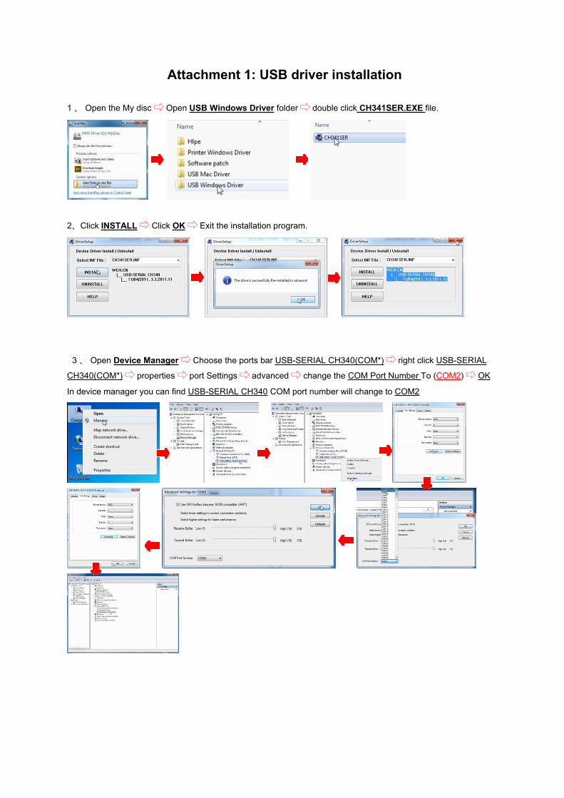
Attachment 1: USB driver installation
1 、 Open the My disc⇨ Open USB Windows Driver folder⇨ double click CH341SER.EXE file.
2、Click INSTALL⇨ Click OK⇨ Exit the installation program.
3 、 Open Device Manager⇨ Choose the ports bar USB-SERIAL CH340(COM*)⇨ right click USB-SERIAL
CH340(COM*)⇨ properties⇨ port Settings⇨ advanced⇨ change the COM Port Number To (COM2)⇨ OK
In device manager you can find USB-SERIAL CH340 COM port number will change to COM2

Attachment 2: Artcut Software Setting
13) Connect the machine with computer via USB cable
2、Install Artcut software ,type a word ⇨ Cut Out
14) Install cutting plotter:Manufacturers choose Jinka ⇨ Device:according to the actual model
⇨ Click Add ⇨ Close
4、Link to:select COM2
5 、 Setup:port setting ⇨ Parameters ⇨ band rate:9600 dat bit:8 check:None stop bit 1
Sequential control:RTS/CTS ⇨ OK ⇨ Change
6、Click:Cut/Plot ⇨ Start;machine will output the data.
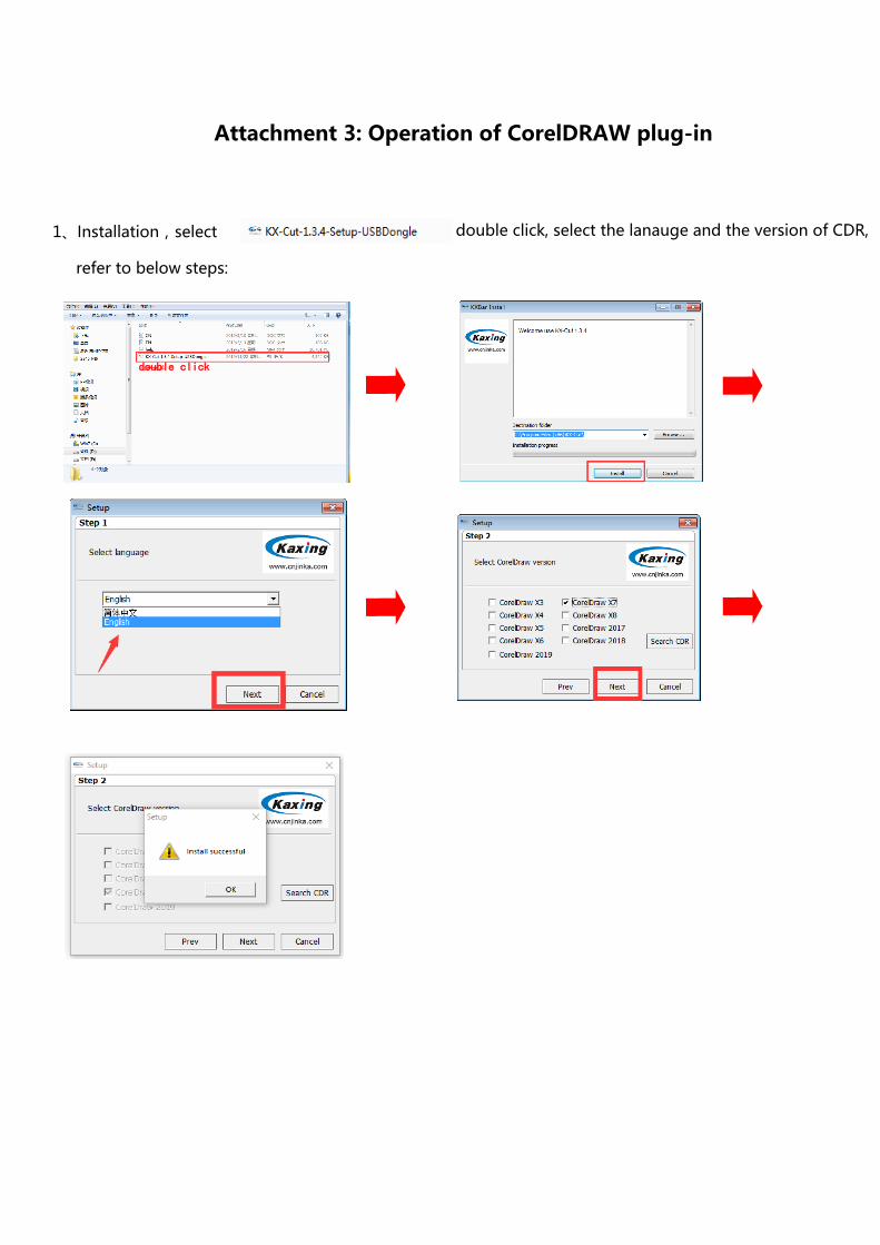
Attachment 3: Operation of CorelDRAW plug-in
1、Installation,select double click, select the lanauge and the version of CDR,
refer to below steps:
double click
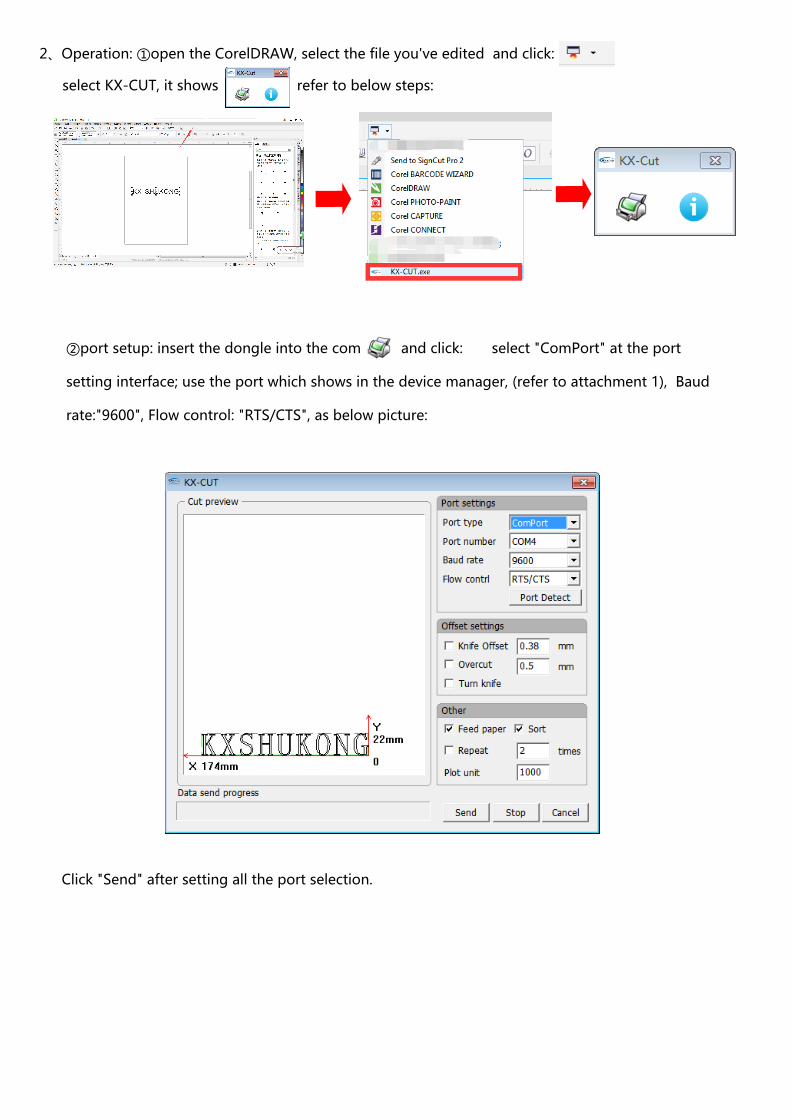
2、Operation: ①open the CorelDRAW, select the file you've edited and click:
select KX-CUT, it shows refer to below steps:
②port setup: insert the dongle into the computer and click: select "ComPort" at the port
setting interface; use the port which shows in the device manager, (refer to attachment 1), Baud
rate:"9600", Flow control: "RTS/CTS", as below picture:
Click "Send" after setting all the port selection.

1. Login
Attachment 4: FLEXI 12 Software Operation
1).First find a computer that can search the internet to register Flexi12.
2).Please use (Google Chrome)browser to visit https://www.saicloud.com
3).Input activation code which can be found on Password of Flexi12 package(note English letters should be
capitalized),then click Activate.
4).Create an account , choose:I am new to the SAi Cloud, input an email address that you often use, click
Create Account.
5).Enter the mailbox used to register just now,after receiving email from SAi Cloud, click the interlinkage in the
email. Fill in the blank with * mark on the top left corner. Press Create Account.
6).Choose:I Accept the Terms and Conditions.
19).Select:Activate Now
8).Then finish registration.

2.Software installation
1).Frist insert software CD into computer CD-ROM,begin installation
In some computer mayappear this dialog box,click ok directly.
2). If computer can visit the internetInput activation code which can be found on Password of Flexi12 package(note English letters should
be capitalized)⇨ Next⇨ Next⇨ F inish
3).If computer can not visit the internetInput activation code which can be found on Password of Flexi12package(note English letters should be
capitalized)⇨ Next⇨ Record computer ID⇨ Record Full computer name⇨ find a computer that can use
(Google Chrome)browser and visit https://www.saicloud.com login the account management interface⇨choose:“License manager” can not link?⇨ Create license⇨ input recorded ID and recorded full computer
name⇨ Create License Now⇨ Download License⇨ back to the installation interface:Import A License File
⇨ choose download license-xxxxx.lsn file⇨ Open⇨ Finish

3. Unload software
Start⇨ Flexi12 folder⇨ License Manager⇨ Remove License From This Computer⇨ record the remove
code⇨ Finish
(1) If computer can visit the internet
Use(Google Chrome)browser to visit https://www.saicloud.com⇨ login to you account management⇨You can find the status is inactivated, that signify the software is remove from your computer successfully.
(2) If computer can not visit the internet
Find a computer that can use(Google Chrome)browser to visit https://www.saicloud.com⇨ login to you
account management⇨ Remove License?⇨ Input removal code⇨ Remove
4.Flexi12 contour cutting operation instruction
20).Connect machine with computer via USB cable , turn on the power
2).Open Production Manager 12 setting⇨ select machine type⇨ Next⇨ Communication Port : COM2
(Refer to device manager)Bits per second:9600 Bat Bit:8 Check:None Stop bit:1 Sequential
control:Hardware⇨ Finish
3).Set compensation value:Double click the plotter device⇨ Cut⇨ tick knife offset⇨ input the value.
Set compensation
value
Click key to move
red dot to the center
of the cross on the
paper
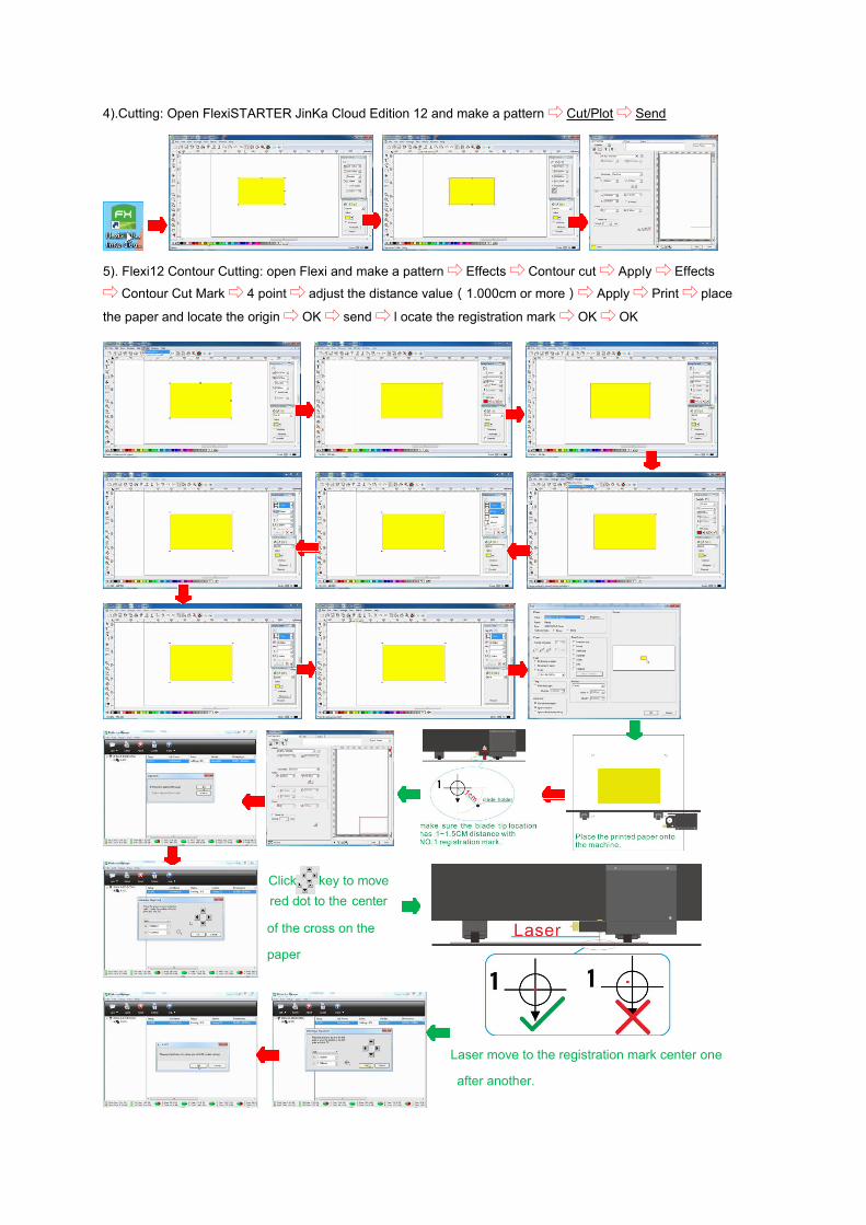
4).Cutting: Open FlexiSTARTER JinKa Cloud Edition 12 and make a pattern⇨ Cut/Plot⇨ Send
5). Flexi12 Contour Cutting: open Flexi and make a pattern⇨ Effects⇨ Contour cut⇨ Apply ⇨ Effects
⇨ Contour Cut Mark⇨ 4 point⇨ adjust the distance value(1.000cm or more)⇨ Apply⇨ Print⇨ place
the paper and locate the origin⇨ OK⇨ send⇨ l ocate the registration mark⇨ OK⇨ OK
Laser move to the registration mark center one
after another.

Attention
1).After the contour cut process, you will find the contour line is not coincide with the printed square. Please use
ruler to check the distance between the two square. Calculate the actual offset value according to the below
formula.
Offset Y = 0 - a
Offset X = 0 - b
Offset Y = 0 +a
Offset X = 0 - b
Or every time you revise the value change Offset Y = Offset X = 0
Offset Y = 0 - a
Offset X = 0 + b
Offset Y = 0 + a
Offset X = 0 + b
3). Input Offset X and Offset Y value in Flexi Cut Contour dialog box.
Cut Contour⇨ Options⇨ Edit⇨ tick Offset X and Offset Y⇨ input the value⇨ OK
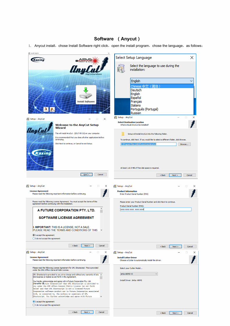
Software (Anycut)1. Anycut install,chose Install Software right click,open the install program,chose the language,as follows:


2.Software using:①Double click to open software
②port setting:click launch image ,choose vinyl spooler
③connection--Add the current cutter,automatic cutter choose “JinKa-721
④choose port:Direct COM Port ⑤choose COM port: USB-serial CH340(COM10)
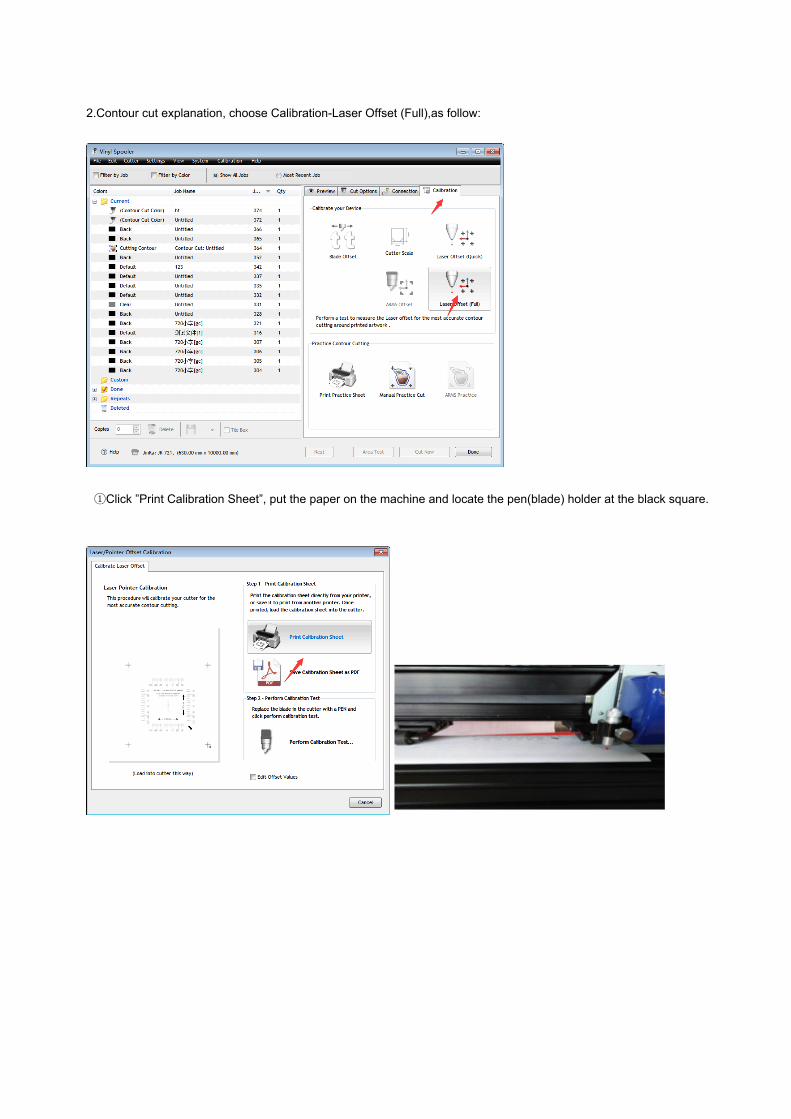
2.Contour cut explanation, choose Calibration-Laser Offset (Full),as follow:
①Click ”Print Calibration Sheet”, put the paper on the machine and locate the pen(blade) holder at the black square.

②Then click “ Perform Calibration Test” as follow:
③Follow the steps what software show and fill the value you get into the software.

④Back to the main interface, add your design and choose it,click and then follow the steps:

⑤Put the paper which one you print and locate the pen (blade) holder, click CUT, wait for the machine working.
Related Documents


![[] 合板の種類 国産合板の大部分は、合板の日本農林 …9 10 その他の合板 合板に使用される主な樹種 ランバーコアー合板 心板(コアー)にランバー(挽き板)、表・裏・添え心板に単板を使用した合板。図のように幅の狭い挽き板(ス](https://static.cupdf.com/doc/110x72/5e761481def0e4530a5e6cb0/-ce-cefoee-9-10-.jpg)