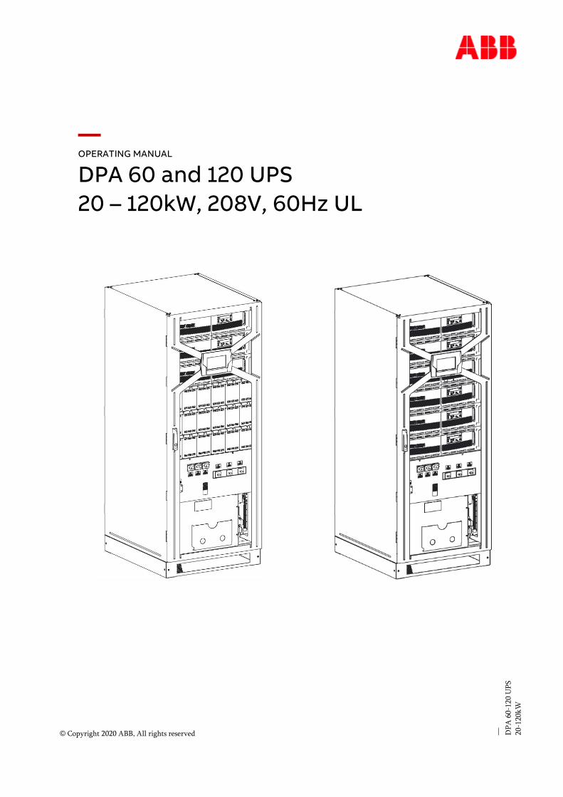
— OPERATING MANUAL DPA 60 and 120 UPS 20 – 120kW, 208V, 60Hz UL — DPA 60-120 UPS 20-120kW © Copyright 2020 ABB, All rights reserved

Welcome message from author
This document is posted to help you gain knowledge. Please leave a comment to let me know what you think about it! Share it to your friends and learn new things together.
Transcript
— OPERATING MANUAL
DPA 60 and 120 UPS
20 – 120kW, 208V, 60Hz UL
—
DP
A 6
0-1
20 U
PS
20-1
20k
W
© Copyright 2020 ABB, All rights reserved
2
—
About this document
—
Document information
File name : 94-1100-00002872_ABB_DPA_060_120_UL_REV-B3.docx
UPS model : DPA 60 UL and DPA 120 UL
Date of issue : 02.08.21
Document number : 94-1100-00002872
Revision : B3
—
Foreword
The UPS System operates with mains, battery or bypass power. It contains components that carry
high currents and voltages. The properly installed UPS System is grounded to earth and NEMA-1 rated
against electrical shock and foreign objects.
COMMISSIONING AND OPERATIONS INSIDE THE UPS
MUST BE PERFORMED BY A CERTIFIED SERVICE
ENGINEER FROM THE MANUFACTURER OR FROM AN
AGENT CERTIFIED BY THE MANUFACTURER.
BY NOT FULFILLING THIS OBLIGATION, THE PRODUCT
MAY VOID ITS WARRANTY.
This user manual contains guidelines to check delivery, installing and commissioning of the UPS and is
intended for people who plan the installation, install, commission and use or service the UPS. The
reader is expected to know the fundamentals of electricity, wiring, electrical components and
electrical schematic symbols.
THE INSTRUCTIONS IN THIS MANUAL MUST BE
FOLLOWED TO PERFORM ANY OPERATION ON THE UPS.
3
— Contents
Safety instructions .................................................................................................................................. 4
1 Important safety instructions ................................................................................................................ 4 1.1 Using this manual....................................................................................................................................... 4 1.2 Safety rules .................................................................................................................................................. 5
User manual ............................................................................................................................................. 9
2 General information ...................................................................................................................................9 2.1 Declaration of safety conformity ........................................................................................................... 9 2.2 Nameplate and identification ............................................................................................................... 10
3 System description .................................................................................................................................. 11 3.1 System architecture ................................................................................................................................ 12 3.2 Basic Module ............................................................................................................................................. 12 3.3 Main elements description..................................................................................................................... 13 3.4 Operating modes ..................................................................................................................................... 17
4 Control & monitoring ............................................................................................................................... 21 4.1 Control panel module .............................................................................................................................. 21 4.2 LCD description ........................................................................................................................................ 23 4.3 Metering .................................................................................................................................................... 24
Installation guide .................................................................................................................................. 27
5 Maintenance & troubleshooting ............................................................................................................ 27 5.1 General maintenance ............................................................................................................................... 27 5.2 Troubleshooting ...................................................................................................................................... 28
6 Packing, transportation & storage ...................................................................................................... 30 6.1 Packing & transportation ...................................................................................................................... 30 6.2 Unpacking .................................................................................................................................................. 31 6.3 Storage ...................................................................................................................................................... 34
7 Installation ................................................................................................................................................. 35 7.1 Environmental condition ........................................................................................................................35 7.2 Environmental condition for UPS with inside battery modules or external battery cabinet..35 7.3 UPS location ............................................................................................................................................. 36 7.4 Heat Dissipation per module ................................................................................................................ 38 7.5 UPS connections ...................................................................................................................................... 38 7.6 Electrical wirings ..................................................................................................................................... 44
8 Communication interfaces .................................................................................................................... 50
9 Commissioning ........................................................................................................................................ 54 9.1 LED colors legend .................................................................................................................................... 54 9.2 Start-up procedure ................................................................................................................................. 54 9.3 Shutdown procedure ............................................................................................................................... 57 9.4 Manual bypass ......................................................................................................................................... 59 9.5 Adding & replacement of a power module ......................................................................................... 61 9.6 Multi-cabinet configuration (option) .................................................................................................. 70 9.7 Multidrop configuration ......................................................................................................................... 72
10 Service options ......................................................................................................................................... 76 10.1 Field installable kits ................................................................................................................................. 76
11 Attachments ............................................................................................................................................. 87 11.1 Technical data sheet ................................................................................................................................ 87
4
—
Safety instructions
—
1 Important safety instructions
1.1 Using this manual
This manual contains important instructions for models DPA 60 UL and DPA 120 UL that should be followed during installation and maintenance of the UPS. It also gives guidelines to check delivery and is intended for people who plan the installation, install, commission and use or service the UPS system and/or the battery cabinet. The reader is expected to know the fundamentals of electricity, wiring, electrical components and electrical schematic symbols
READ ALL SAFETY AND OPERATING INSTRUCTIONS BEFORE OPERATING THE UPS SYSTEM AND/OR THE BATTERY CABINET. ADHERE TO ALL WARNINGS ON
THE UNIT AND IN THIS MANUAL.
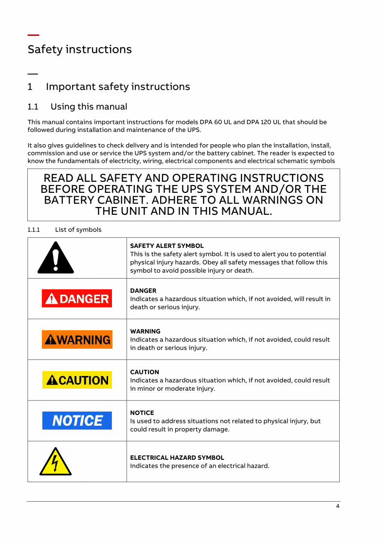
1.1.1 List of symbols
SAFETY ALERT SYMBOL
This is the safety alert symbol. It is used to alert you to potential
physical injury hazards. Obey all safety messages that follow this
symbol to avoid possible injury or death.
DANGER
Indicates a hazardous situation which, if not avoided, will result in
death or serious injury.
WARNING
Indicates a hazardous situation which, if not avoided, could result
in death or serious injury.
CAUTION
Indicates a hazardous situation which, if not avoided, could result
in minor or moderate injury.
NOTICE
Is used to address situations not related to physical injury, but
could result in property damage.
ELECTRICAL HAZARD SYMBOL
Indicates the presence of an electrical hazard.
5
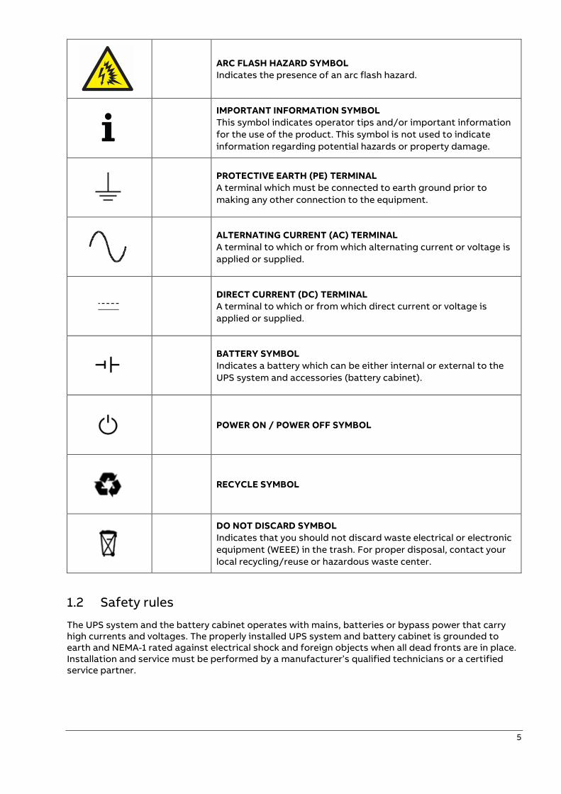
ARC FLASH HAZARD SYMBOL
Indicates the presence of an arc flash hazard.
IMPORTANT INFORMATION SYMBOL
This symbol indicates operator tips and/or important information
for the use of the product. This symbol is not used to indicate
information regarding potential hazards or property damage.
PROTECTIVE EARTH (PE) TERMINAL
A terminal which must be connected to earth ground prior to
making any other connection to the equipment.
ALTERNATING CURRENT (AC) TERMINAL
A terminal to which or from which alternating current or voltage is
applied or supplied.
DIRECT CURRENT (DC) TERMINAL
A terminal to which or from which direct current or voltage is
applied or supplied.
BATTERY SYMBOL
Indicates a battery which can be either internal or external to the
UPS system and accessories (battery cabinet).
POWER ON / POWER OFF SYMBOL
RECYCLE SYMBOL
DO NOT DISCARD SYMBOL
Indicates that you should not discard waste electrical or electronic
equipment (WEEE) in the trash. For proper disposal, contact your
local recycling/reuse or hazardous waste center.
1.2 Safety rules
The UPS system and the battery cabinet operates with mains, batteries or bypass power that carry high currents and voltages. The properly installed UPS system and battery cabinet is grounded to earth and NEMA-1 rated against electrical shock and foreign objects when all dead fronts are in place. Installation and service must be performed by a manufacturer’s qualified technicians or a certified service partner.
6
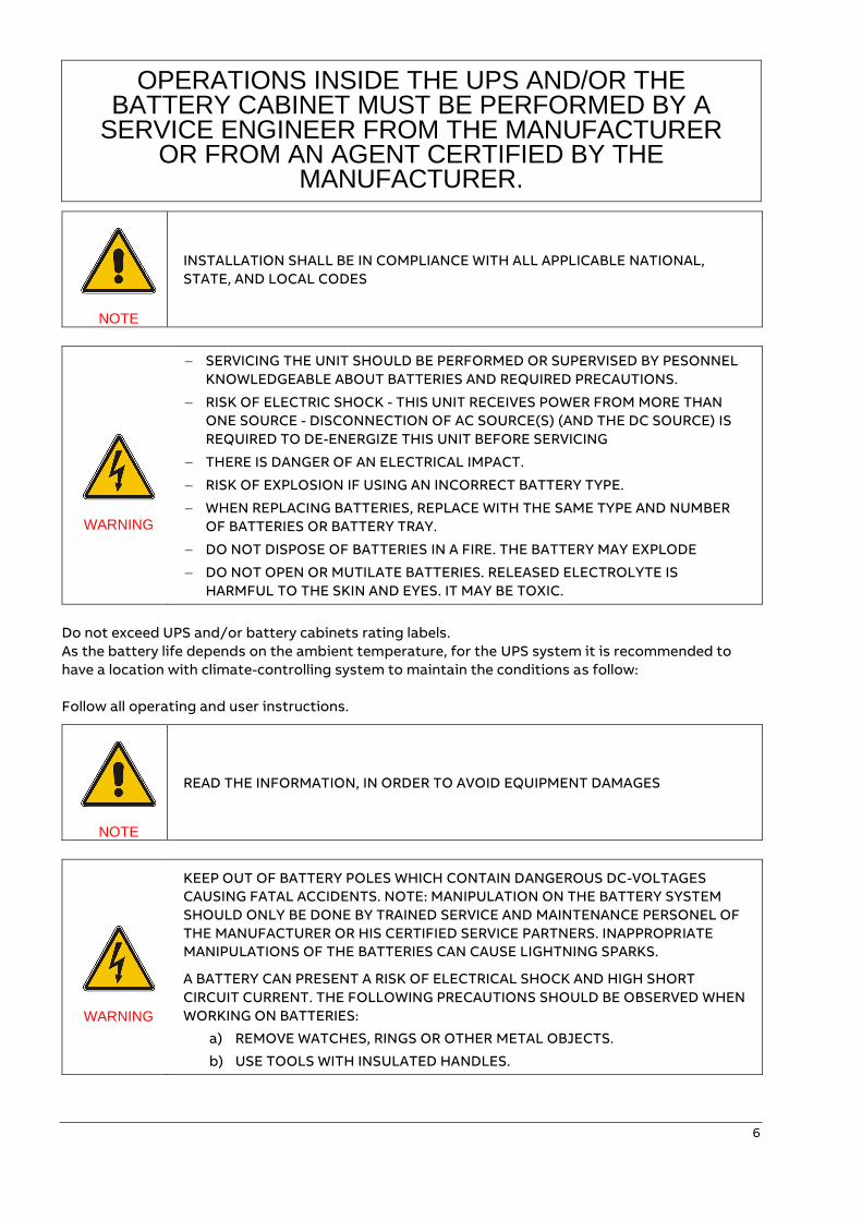
OPERATIONS INSIDE THE UPS AND/OR THE BATTERY CABINET MUST BE PERFORMED BY A
SERVICE ENGINEER FROM THE MANUFACTURER OR FROM AN AGENT CERTIFIED BY THE
MANUFACTURER.
NOTE
INSTALLATION SHALL BE IN COMPLIANCE WITH ALL APPLICABLE NATIONAL,
STATE, AND LOCAL CODES
WARNING
− SERVICING THE UNIT SHOULD BE PERFORMED OR SUPERVISED BY PESONNEL
KNOWLEDGEABLE ABOUT BATTERIES AND REQUIRED PRECAUTIONS.
− RISK OF ELECTRIC SHOCK - THIS UNIT RECEIVES POWER FROM MORE THAN
ONE SOURCE - DISCONNECTION OF AC SOURCE(S) (AND THE DC SOURCE) IS
REQUIRED TO DE-ENERGIZE THIS UNIT BEFORE SERVICING
− THERE IS DANGER OF AN ELECTRICAL IMPACT.
− RISK OF EXPLOSION IF USING AN INCORRECT BATTERY TYPE.
− WHEN REPLACING BATTERIES, REPLACE WITH THE SAME TYPE AND NUMBER
OF BATTERIES OR BATTERY TRAY.
− DO NOT DISPOSE OF BATTERIES IN A FIRE. THE BATTERY MAY EXPLODE
− DO NOT OPEN OR MUTILATE BATTERIES. RELEASED ELECTROLYTE IS
HARMFUL TO THE SKIN AND EYES. IT MAY BE TOXIC.
Do not exceed UPS and/or battery cabinets rating labels.
As the battery life depends on the ambient temperature, for the UPS system it is recommended to
have a location with climate-controlling system to maintain the conditions as follow:
Follow all operating and user instructions.
NOTE
READ THE INFORMATION, IN ORDER TO AVOID EQUIPMENT DAMAGES
WARNING
KEEP OUT OF BATTERY POLES WHICH CONTAIN DANGEROUS DC-VOLTAGES
CAUSING FATAL ACCIDENTS. NOTE: MANIPULATION ON THE BATTERY SYSTEM
SHOULD ONLY BE DONE BY TRAINED SERVICE AND MAINTENANCE PERSONEL OF
THE MANUFACTURER OR HIS CERTIFIED SERVICE PARTNERS. INAPPROPRIATE
MANIPULATIONS OF THE BATTERIES CAN CAUSE LIGHTNING SPARKS.
A BATTERY CAN PRESENT A RISK OF ELECTRICAL SHOCK AND HIGH SHORT
CIRCUIT CURRENT. THE FOLLOWING PRECAUTIONS SHOULD BE OBSERVED WHEN
WORKING ON BATTERIES:
a) REMOVE WATCHES, RINGS OR OTHER METAL OBJECTS.
b) USE TOOLS WITH INSULATED HANDLES.
7
c) WEAR RUBBER GLOVES AND BOOTS.
d) DO NOT LAY TOOLS OR METAL PARTS ON TOP OF BATTERIES.
e) DISCONNECT THE CHARGING SOURCE PRIOR TO CONNECTING OR
DISCONNECTING BATTERY TERMINALS.
f) DETERMINE IF BATTERY IS INADVERTENTLY GROUNDED. IF
INADVERTENTLY GROUNDED, REMOVE SOURCE FROM GROUND.
CONTACT WITH ANY PART OF A GROUNDED BATTERY CAN RESULT IN
ELECTRAL SHOCK. THE LIKELIHOOD OF SUCH SHOCK CAN BE REDUCED IF
SUCH GROUNDS ARE REMOVED DURING INSTALLATION AND
MAINTENANCE (APPLICABLE TO EQUIPMENT AND REMOTE BATTERY
SUPPLIES NOT HAVING GROUNDED SUPPLY CIRCUIT.
NOTE
THE UNIT IS NOT PROVIDED WITH AN INTERNAL INPUT SWITCH. TO SHUTDOWN
THE UNIT YOU MUST PROVIDE A BREAKER IN THE INSTALLATION BUILDING.
NOTE
THE EQUIPMENT IS PROVIDED WITHOUT INPUT AND OUTPUT BREAKERS, A
READILY ACCESSIBLE DISCONNECT DEVICE SHALL BE INCORPORATED EXTERNAL
TO THE EQUIMPENT.
NOTE
THE UNIT, THE BATTERY CABINET AND THE BATTERIES ARE HEAVY AND MAY TIP
DURING TRANSPORTATION CAUSING SERIOUS INJURY IF UNPACKING
INSTRUCTIONS ARE NOT CLOSELY FOLLOWED.
NOTE
SEALED BATTERIES MUST NEVER BE STORED IN A DISCHARGED OR PARTIALLY
DISCHARGED STATE.
EXTREME TEMPERATURE, UNDER- AND OVERCHARGE AND OVERDISCHARGE WILL
DESTROY BATTERIES.
The only user operations permitted are:
• Use of the LCD control panel (DPA Display) and of the Maintenance Bypass
• Start up and shutdown of the UPS of the user field (excluding the commissioning start up)
• Operation of additional connectivity modules:
o SNMP adapters and their software
o Modem/GSM or Modem/Ethernet adapters and their software
The user must follow the precautions and only perform the described operations. Also in these
measures the operator of the UPS System must adhere to the instructions in this manual. Any
deviations from the instructions could be dangerous to the user or cause accidental load loss.
8
THE MANUFACTURER DOES NOT TAKE ANY RESPONSIBILITY FOR DAMAGES CAUSED THROUGH INCORRECT MANIPULATIONS OF THE UPS SYSTEM.
WARNING
IT IS PROHIBITED TO REMOVE ANY SCREWS FROM THE UPS SYSTEM OR FROM
ANY OPTIONAL PART (E.G. BATTERY CABINET). THERE IS A DANGER OF
ELECTRICAL SHOCK.
WARNING
HIGH LEAKAGE CURRENTS:
BEFORE CONNECTING THE MAINS YOU MUST ENSURE THAT THERE IS A PROPER
EARTH CONNECTION.
WARNING
THE USER MUST DISPLAY A WARNING SHIELD ON ALL PRIMARY UPS CIRCUIT
BREAKERS. THE SERVICE PERSONNEL HAS TO BE INFORMED ABOUT DANGEROUS
VOLTAGES. THE WARNING PANELS MUST CONTAIN THE FOLLOWING TEXT (OR
SIMILAR): “BEFORE STARTING WITH THE MAINTENANCE WORK ON THE CIRCUIT
BREAKERS MAKE SURE THE UPS IS ISOLATED”.
WARNING
ALL THE INPUT/OUTPUT PORTS ARE CLASS 2 (SELV CIRCUITS). PLEASE MAINTAIN
SECURITY WHEN CONNECTING TO OTHER DEVICES.
9
—
User manual
—
2 General information
THIS IS A PRODUCT FOR COMMERCIAL AND INDUSTRIAL APPLICATION IN THE
SECOND ENVIRONMENT AS DEFINED IN IEC/EN 62040-2 CHAPTER 4
INSTALLATION RESTRICTIONS OR ADDITIONAL MEASURES MAY BE NEEDED TO
PREVENT DISTURBANCES.
The UPS must be installed according to the recommendations in this manual. To operate the UPS at
peak efficiency, your installation site should meet the environmental parameters outlined in this manual.
Excessive amount of dust in the operating environment of UPS may cause damage or lead to
malfunction. The UPS should be always protected from the outside weather and sunshine. If you intend
to operate the system at an altitude higher than 3,281 feet [ 1000 meters] above sea level, contact your
local sales or service office for important information about high altitude operation. The operating
environment must meet the weight, airflow, size and clearance requirements specified in the technical
datasheet.
Under no circumstances the UPS should be installed in an airtight room, in the presence of flammable
gases, or in an environment exceeding the specification.
The basic environmental requirements of the UPS system are:
• Ambient Temperature Range: 32 – 104˚F [0 to +40˚C]
• Recommended Operating Range: 68 – 77˚F [+20 to +25˚C]
• Maximum Relative Humidity: 95% (non-condensing)
The UPS cabinet uses forced air cooling to regulate internal component temperature. Air inlets are in
the bottom sides and front of the cabinet, and outlets in the rear of the cabinet. You must allow
clearance at the rear of the cabinet for proper air circulation. Refer to the chapter 7.3: UPS and battery
location.
2.1 Declaration of safety conformity
The product has the CE marking in compliance with the following
European directives:
• Low Voltage Directive: 2006/95/EC
• EMC Directive: 2004/108/EC
Declaration of conformity with UPS harmonized standards and directives EN
62040-1-1 (Safety) and EN 62040-2 (EMC) are available as separate document.
Product Standards Standards
Safety Standard: IEC/EN 62040-1
IEC/EN 60950-1
UL 60950-1
UL 1778-5, 5th edition
Electromagnetic Compatibility
Standard (EMC):
IEC/EN 62040-2
Emission cat. C3
Immunity cat. C3
IEC/EN 61000-6-2
IEC/EN 61000-6-4
IEC/EN 61000-4-2
IEC/EN 61000-4-3
IEC/EN 61000-4-4
IEC/EN 61000-4-5
IEC/EN 61000-4-6
Performance Standard: IEC/EN 62040-3
10
The DPA will provide your critical equipment with a steady and reliable power supply for many years.
The unique and modular UPS DPA belongs to the newest generation of midrange 3-phase UPS-
Systems. High reliability, low operating cost and excellent electrical performance are only some of the
highlights of this innovative UPS solution.
The criteria and methods implemented at ABB for the design and manufacture correspond to the
most stringent quality standards.
The manufacturer is certified successfully in every area according to the model of the International
Standard:
ISO 9001/EN 29001. The Certification of UPS with the operating performance according to the
standard IEC 62040-3 and VDE 0558 Part 530 is accomplished.
With it the ABB UPS has the Classification Code VFl-SS-111.
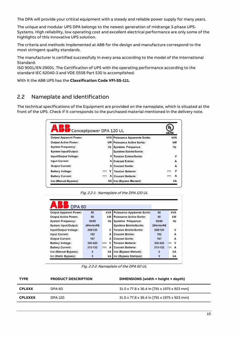
2.2 Nameplate and identification
The technical specifications of the Equipment are provided on the nameplate, which is situated at the
front of the UPS. Check if it corresponds to the purchased material mentioned in the delivery note.
Fig. 2.2-1: Nameplate of the DPA 120 UL
Fig. 2.2-2: Nameplate of the DPA 60 UL
TYPE PRODUCT DESCRIPTION DIMENSIONS (width × height × depth)
CPLXXX DPA 60 31.0 x 77.8 x 36.4 in [791 x 1975 x 923 mm]
CPLXXXX DPA 120 31.0 x 77.8 x 36.4 in [791 x 1975 x 923 mm]
11
—
3 System description
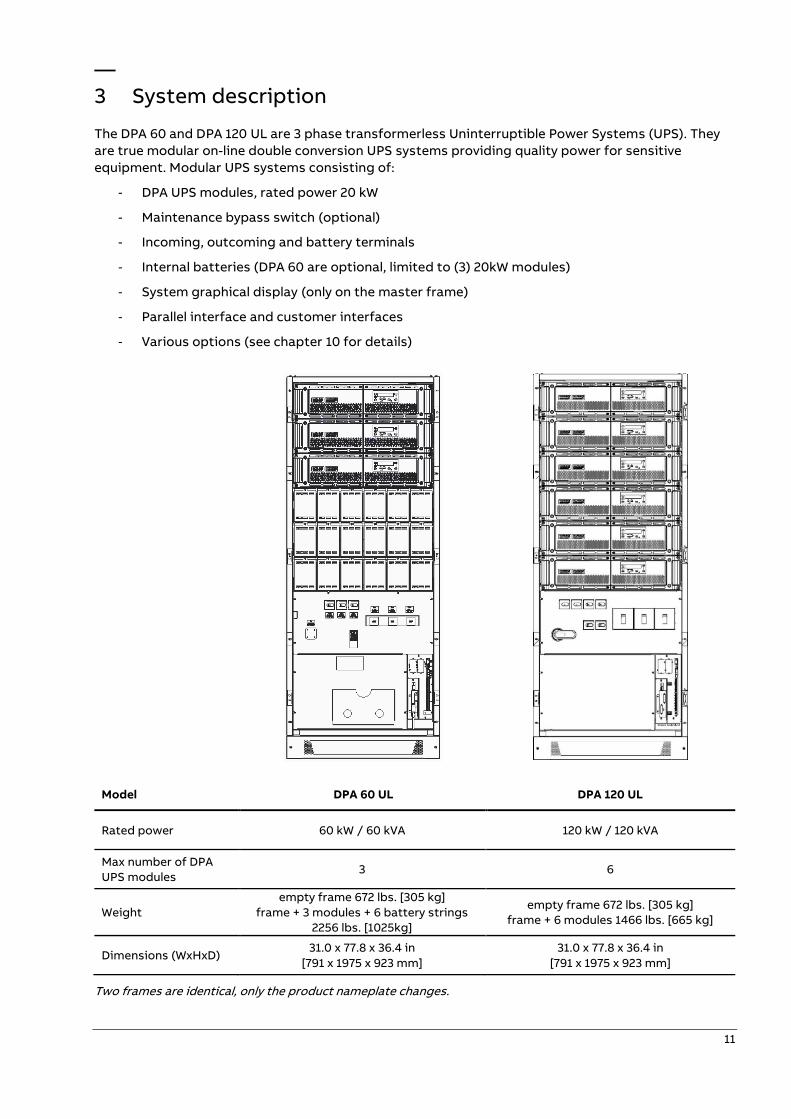
The DPA 60 and DPA 120 UL are 3 phase transformerless Uninterruptible Power Systems (UPS). They
are true modular on-line double conversion UPS systems providing quality power for sensitive
equipment. Modular UPS systems consisting of:
- DPA UPS modules, rated power 20 kW
- Maintenance bypass switch (optional)
- Incoming, outcoming and battery terminals
- Internal batteries (DPA 60 are optional, limited to (3) 20kW modules)
- System graphical display (only on the master frame)
- Parallel interface and customer interfaces
- Various options (see chapter 10 for details)
Model DPA 60 UL DPA 120 UL
Rated power 60 kW / 60 kVA 120 kW / 120 kVA
Max number of DPA
UPS modules 3 6
Weight
empty frame 672 lbs. [305 kg]
frame + 3 modules + 6 battery strings
2256 lbs. [1025kg]
empty frame 672 lbs. [305 kg]
frame + 6 modules 1466 lbs. [665 kg]
Dimensions (WxHxD) 31.0 x 77.8 x 36.4 in
[791 x 1975 x 923 mm]
31.0 x 77.8 x 36.4 in
[791 x 1975 x 923 mm]
Two frames are identical, only the product nameplate changes.
12
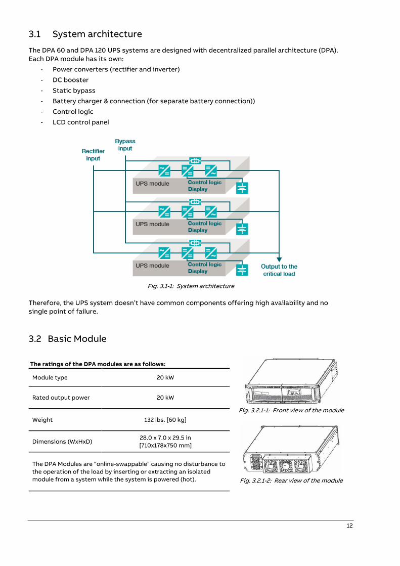
3.1 System architecture
The DPA 60 and DPA 120 UPS systems are designed with decentralized parallel architecture (DPA).
Each DPA module has its own:
- Power converters (rectifier and inverter)
- DC booster
- Static bypass
- Battery charger & connection (for separate battery connection))
- Control logic
- LCD control panel
Fig. 3.1-1: System architecture
Therefore, the UPS system doesn’t have common components offering high availability and no
single point of failure.
3.2 Basic Module
The ratings of the DPA modules are as follows:
Fig. 3.2.1-1: Front view of the module
Fig. 3.2.1-2: Rear view of the module
Module type 20 kW
Rated output power 20 kW
Weight 132 lbs. [60 kg]
Dimensions (WxHxD) 28.0 x 7.0 x 29.5 in
[710x178x750 mm]
The DPA Modules are “online-swappable” causing no disturbance to
the operation of the load by inserting or extracting an isolated
module from a system while the system is powered (hot).
13
3.3 Main elements description
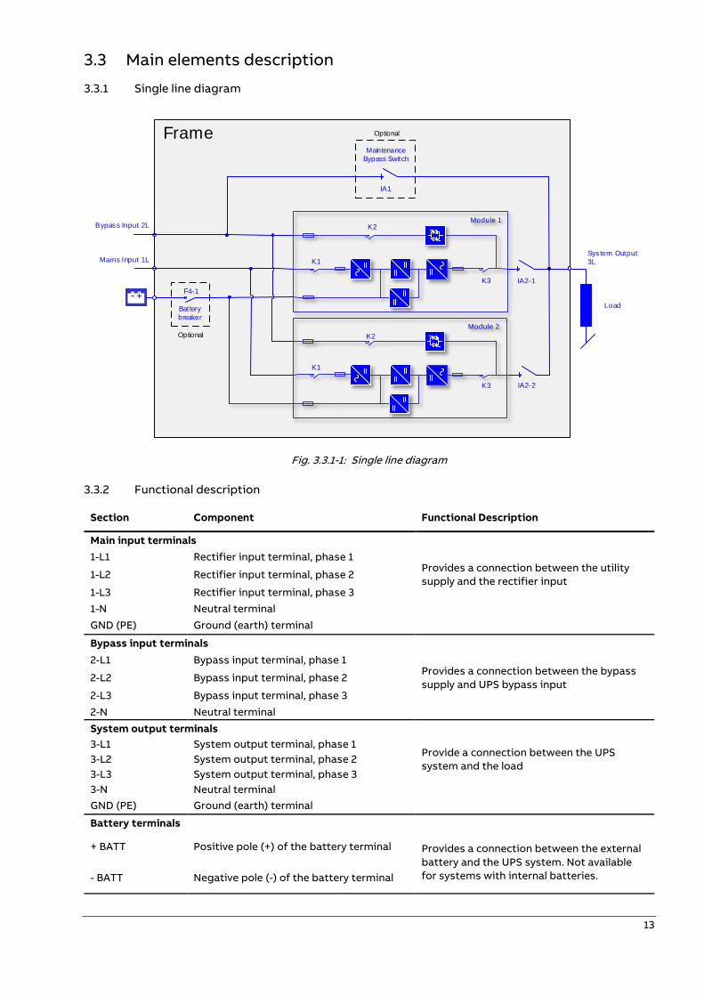
3.3.1 Single line diagram
F4-1
IA1
System Output
3L
Bypass Input 2L
Mains Input 1L
Maintenance
Bypass Switch
Module 1
Module 2
LoadBattery
breaker
K2
K1
K2
IA2-1
IA2-2
Optional
OptionalFrame
K3
K3
K1
Fig. 3.3.1-1: Single line diagram
3.3.2 Functional description
Section Component Functional Description
Main input terminals
1-L1 Rectifier input terminal, phase 1 Provides a connection between the utility
supply and the rectifier input 1-L2 Rectifier input terminal, phase 2
1-L3 Rectifier input terminal, phase 3
1-N Neutral terminal
GND (PE) Ground (earth) terminal
Bypass input terminals
2-L1 Bypass input terminal, phase 1 Provides a connection between the bypass
supply and UPS bypass input 2-L2 Bypass input terminal, phase 2
2-L3 Bypass input terminal, phase 3
2-N Neutral terminal
System output terminals
3-L1 System output terminal, phase 1 Provide a connection between the UPS
system and the load 3-L2 System output terminal, phase 2
3-L3 System output terminal, phase 3
3-N Neutral terminal
GND (PE) Ground (earth) terminal
Battery terminals
+ BATT Positive pole (+) of the battery terminal Provides a connection between the external
battery and the UPS system. Not available
for systems with internal batteries. - BATT Negative pole (-) of the battery terminal
14
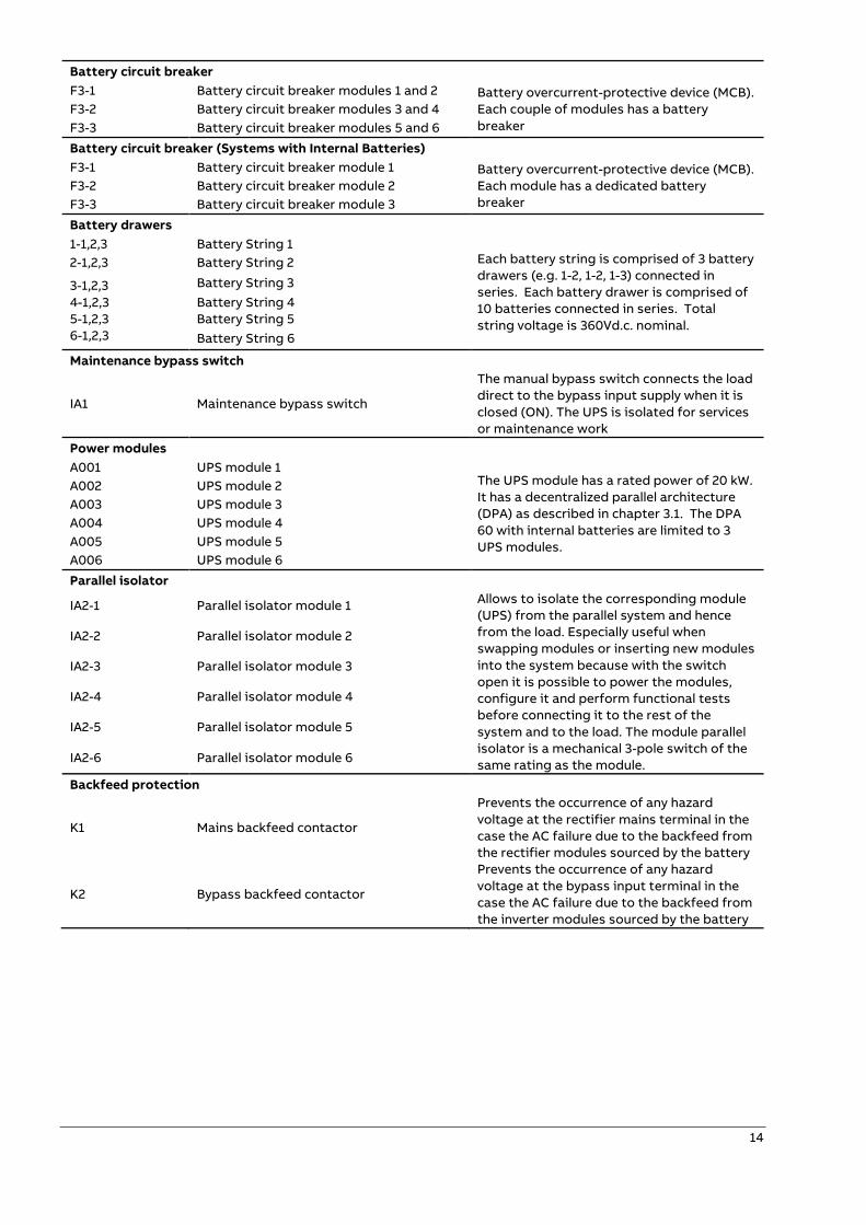
Battery circuit breaker
F3-1 Battery circuit breaker modules 1 and 2 Battery overcurrent-protective device (MCB).
Each couple of modules has a battery
breaker
F3-2 Battery circuit breaker modules 3 and 4
F3-3 Battery circuit breaker modules 5 and 6
Battery circuit breaker (Systems with Internal Batteries)
F3-1 Battery circuit breaker module 1 Battery overcurrent-protective device (MCB).
Each module has a dedicated battery
breaker
F3-2 Battery circuit breaker module 2
F3-3 Battery circuit breaker module 3
Battery drawers
1-1,2,3 Battery String 1 Each battery string is comprised of 3 battery
drawers (e.g. 1-2, 1-2, 1-3) connected in
series. Each battery drawer is comprised of
10 batteries connected in series. Total
string voltage is 360Vd.c. nominal.
2-1,2,3 Battery String 2
3-1,2,3
4-1,2,3
5-1,2,3
6-1,2,3
Battery String 3
Battery String 4
Battery String 5
Battery String 6
Maintenance bypass switch
IA1 Maintenance bypass switch
The manual bypass switch connects the load
direct to the bypass input supply when it is
closed (ON). The UPS is isolated for services
or maintenance work
Power modules
A001 UPS module 1 The UPS module has a rated power of 20 kW.
It has a decentralized parallel architecture
(DPA) as described in chapter 3.1. The DPA
60 with internal batteries are limited to 3
UPS modules.
A002 UPS module 2
A003 UPS module 3
A004 UPS module 4
A005 UPS module 5
A006 UPS module 6
Parallel isolator
IA2-1 Parallel isolator module 1 Allows to isolate the corresponding module
(UPS) from the parallel system and hence
from the load. Especially useful when
swapping modules or inserting new modules
into the system because with the switch
open it is possible to power the modules,
configure it and perform functional tests
before connecting it to the rest of the
system and to the load. The module parallel
isolator is a mechanical 3-pole switch of the
same rating as the module.
IA2-2 Parallel isolator module 2
IA2-3 Parallel isolator module 3
IA2-4 Parallel isolator module 4
IA2-5 Parallel isolator module 5
IA2-6 Parallel isolator module 6
Backfeed protection
K1 Mains backfeed contactor
Prevents the occurrence of any hazard
voltage at the rectifier mains terminal in the
case the AC failure due to the backfeed from
the rectifier modules sourced by the battery
K2 Bypass backfeed contactor
Prevents the occurrence of any hazard
voltage at the bypass input terminal in the
case the AC failure due to the backfeed from
the inverter modules sourced by the battery
15
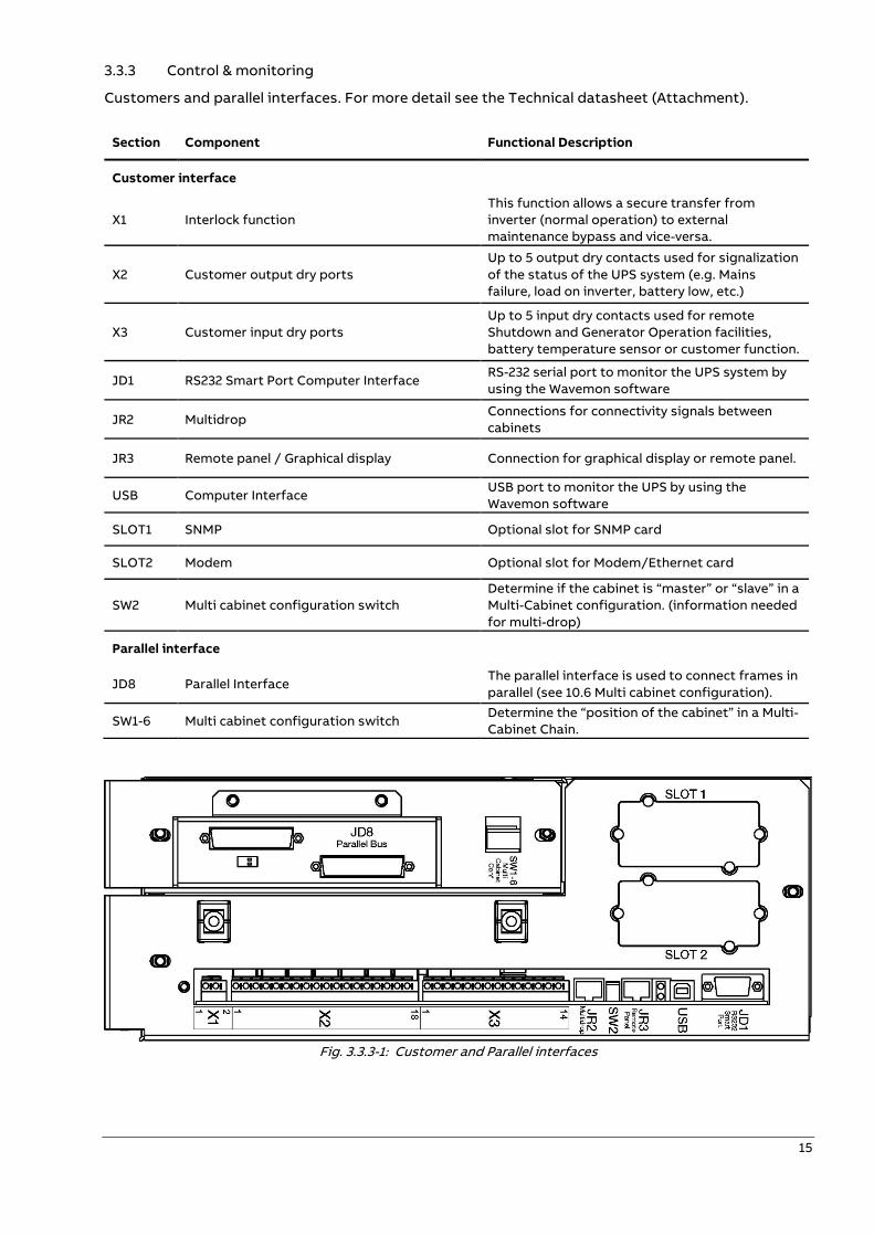
3.3.3 Control & monitoring
Customers and parallel interfaces. For more detail see the Technical datasheet (Attachment).
Section Component Functional Description
Customer interface
X1 Interlock function
This function allows a secure transfer from
inverter (normal operation) to external
maintenance bypass and vice-versa.
X2 Customer output dry ports
Up to 5 output dry contacts used for signalization
of the status of the UPS system (e.g. Mains
failure, load on inverter, battery low, etc.)
X3 Customer input dry ports
Up to 5 input dry contacts used for remote
Shutdown and Generator Operation facilities,
battery temperature sensor or customer function.
JD1 RS232 Smart Port Computer Interface RS-232 serial port to monitor the UPS system by
using the Wavemon software
JR2 Multidrop Connections for connectivity signals between
cabinets
JR3 Remote panel / Graphical display Connection for graphical display or remote panel.
USB Computer Interface USB port to monitor the UPS by using the
Wavemon software
SLOT1 SNMP Optional slot for SNMP card
SLOT2 Modem Optional slot for Modem/Ethernet card
SW2 Multi cabinet configuration switch
Determine if the cabinet is “master” or “slave” in a
Multi-Cabinet configuration. (information needed
for multi-drop)
Parallel interface
JD8 Parallel Interface The parallel interface is used to connect frames in
parallel (see 10.6 Multi cabinet configuration).
SW1-6 Multi cabinet configuration switch Determine the “position of the cabinet” in a Multi-
Cabinet Chain.
Fig. 3.3.3-1: Customer and Parallel interfaces
16
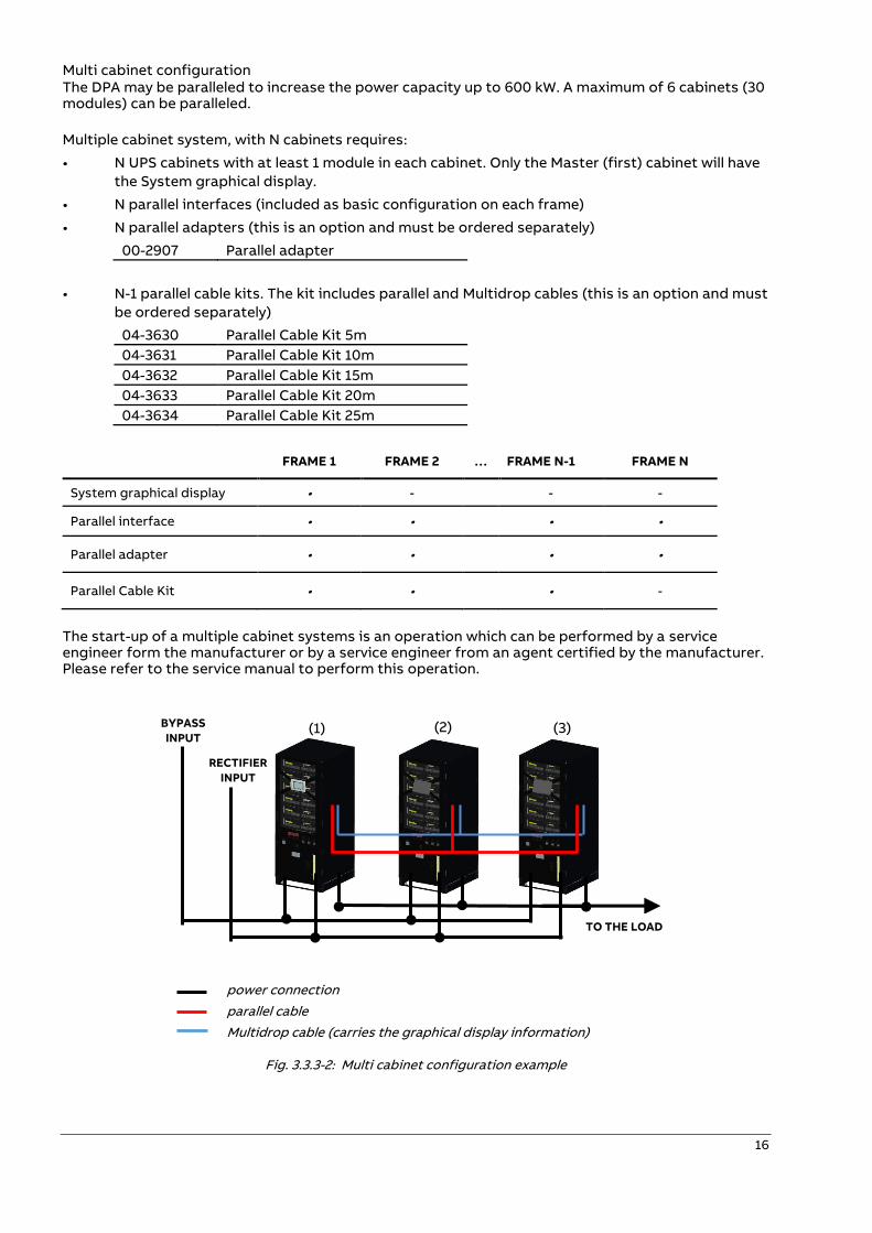
Multi cabinet configuration The DPA may be paralleled to increase the power capacity up to 600 kW. A maximum of 6 cabinets (30 modules) can be paralleled.
Multiple cabinet system, with N cabinets requires:
• N UPS cabinets with at least 1 module in each cabinet. Only the Master (first) cabinet will have
the System graphical display.
• N parallel interfaces (included as basic configuration on each frame)
• N parallel adapters (this is an option and must be ordered separately)
00-2907 Parallel adapter
• N-1 parallel cable kits. The kit includes parallel and Multidrop cables (this is an option and must
be ordered separately)
04-3630 Parallel Cable Kit 5m
04-3631 Parallel Cable Kit 10m
04-3632 Parallel Cable Kit 15m
04-3633 Parallel Cable Kit 20m
04-3634 Parallel Cable Kit 25m
FRAME 1 FRAME 2 … FRAME N-1 FRAME N
System graphical display • - - -
Parallel interface • • • •
Parallel adapter • • • •
Parallel Cable Kit • • • -
The start-up of a multiple cabinet systems is an operation which can be performed by a service engineer form the manufacturer or by a service engineer from an agent certified by the manufacturer. Please refer to the service manual to perform this operation.
power connection
parallel cable
Multidrop cable (carries the graphical display information)
Fig. 3.3.3-2: Multi cabinet configuration example
TO THE LOAD
(1) (2) (3) BYPASS
INPUT
RECTIFIER
INPUT
17
3.4 Operating modes
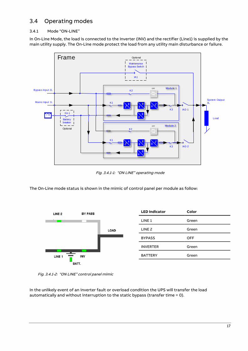
3.4.1 Mode “ON-LINE”
In On-Line Mode, the load is connected to the Inverter (INV) and the rectifier (Line1) is supplied by the
main utility supply. The On-Line mode protect the load from any utility main disturbance or failure.
F4-1
IA1
System Output
3L
Bypass Input 2L
Mains Input 1L
Maintenance
Bypass Switch
Module 1
Module 2
LoadBattery
breaker
K2
K1
K2
IA2-1
IA2-2
Optional
OptionalFrame
K3
K3
K1
OFF
OFF
Fig. 3.4.1-1: “ON LINE” operating mode
The On-Line mode status is shown in the mimic of control panel per module as follow:
LED Indicator Color
LINE 1 Green
LINE 2 Green
BYPASS OFF
INVERTER Green
BATTERY Green
Fig. 3.4.1-2: “ON LINE” control panel mimic
In the unlikely event of an inverter fault or overload condition the UPS will transfer the load
automatically and without interruption to the static bypass (transfer time = 0).
18
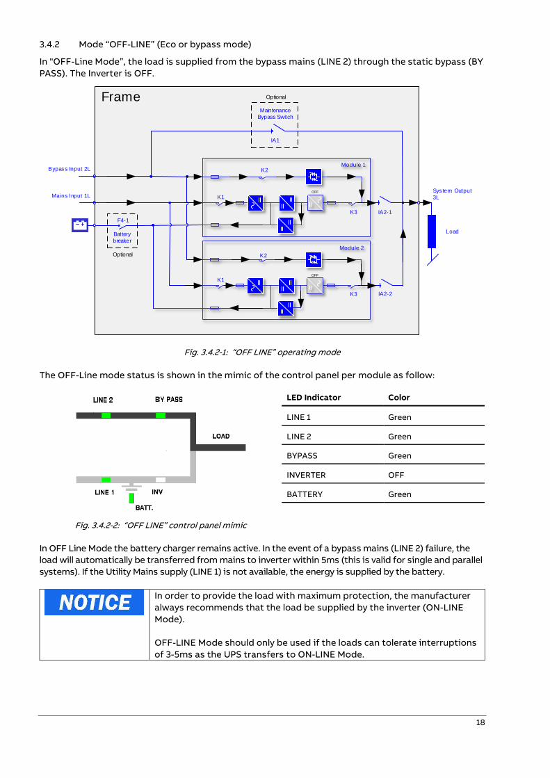
3.4.2 Mode “OFF-LINE” (Eco or bypass mode)
In "OFF-Line Mode”, the load is supplied from the bypass mains (LINE 2) through the static bypass (BY
PASS). The Inverter is OFF.
F4-1
IA1
System Output
3L
Bypass Input 2L
Mains Input 1L
Maintenance
Bypass Switch
Module 1
Module 2
LoadBattery
breaker
K2
K1
K2
IA2-1
IA2-2
Optional
OptionalFrame
K3
K3
K1
OFF
OFF
Fig. 3.4.2-1: “OFF LINE” operating mode
The OFF-Line mode status is shown in the mimic of the control panel per module as follow:
LED Indicator Color
LINE 1 Green
LINE 2 Green
BYPASS Green
INVERTER OFF
BATTERY Green
Fig. 3.4.2-2: “OFF LINE” control panel mimic
In OFF Line Mode the battery charger remains active. In the event of a bypass mains (LINE 2) failure, the
load will automatically be transferred from mains to inverter within 5ms (this is valid for single and parallel
systems). If the Utility Mains supply (LINE 1) is not available, the energy is supplied by the battery.
In order to provide the load with maximum protection, the manufacturer
always recommends that the load be supplied by the inverter (ON-LINE
Mode).
OFF-LINE Mode should only be used if the loads can tolerate interruptions
of 3-5ms as the UPS transfers to ON-LINE Mode.
19
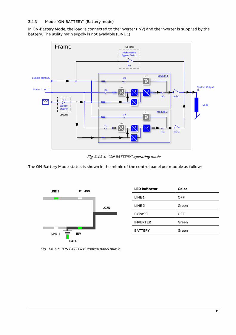
3.4.3 Mode “ON-BATTERY” (Battery mode)
In ON-Battery Mode, the load is connected to the inverter (INV) and the inverter is supplied by the
battery. The utility main supply is not available (LINE 1)
F4-1
IA1
System Output
3L
Bypass Input 2L
Mains Input 1L
Maintenance
Bypass Switch
Module 1
Module 2
LoadBattery
breaker
K2
K1
K2
IA2-1
IA2-2
Optional
OptionalFrame
K3
K3
K1
OFF
OFF
OFF
OFF
Fig. 3.4.3-1: “ON BATTERY” operating mode
The ON-Battery Mode status is shown in the mimic of the control panel per module as follow:
LED Indicator Color
LINE 1 OFF
LINE 2 Green
BYPASS OFF
INVERTER Green
BATTERY Green
Fig. 3.4.3-2: “ON BATTERY” control panel mimic
20
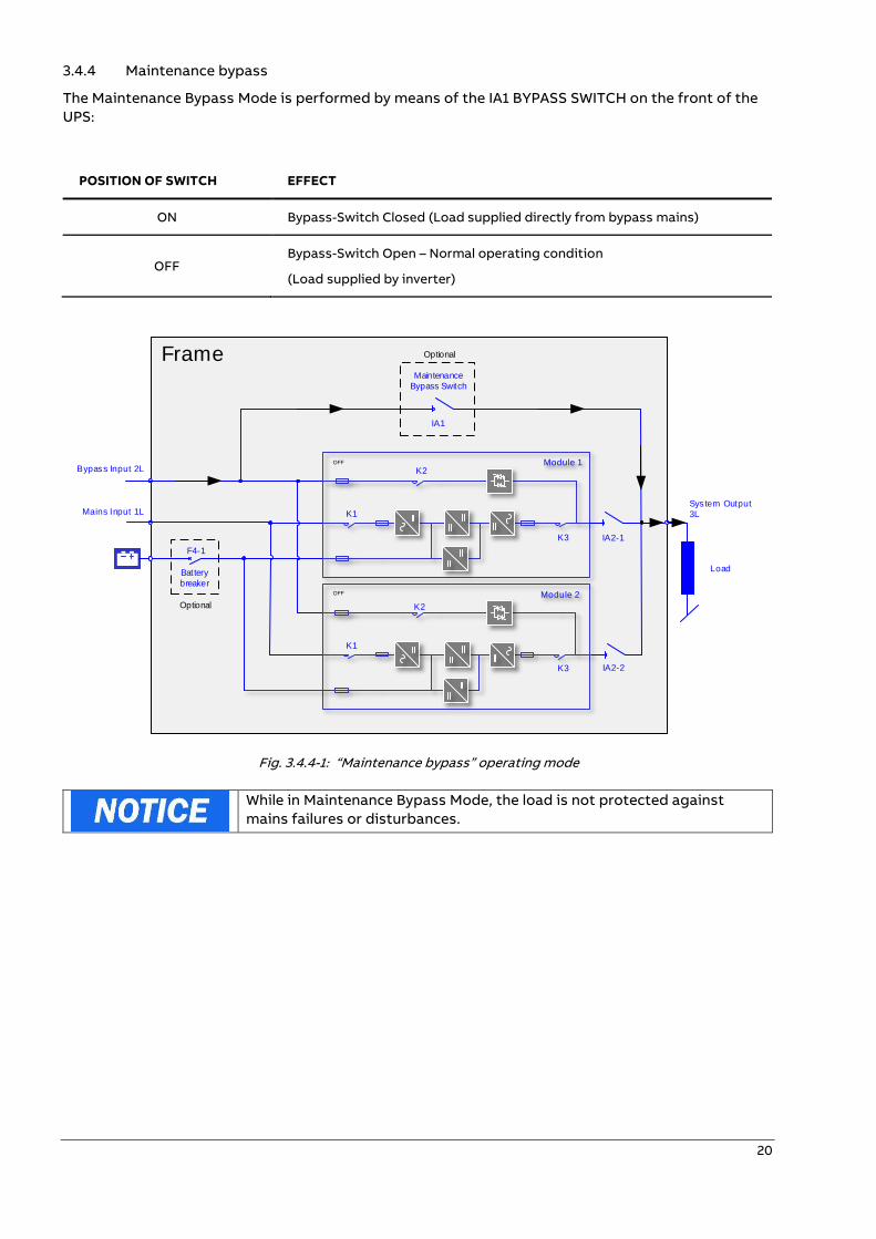
3.4.4 Maintenance bypass
The Maintenance Bypass Mode is performed by means of the IA1 BYPASS SWITCH on the front of the
UPS:
POSITION OF SWITCH EFFECT
ON Bypass-Switch Closed (Load supplied directly from bypass mains)
OFF Bypass-Switch Open – Normal operating condition
(Load supplied by inverter)
F4-1
IA1
System Output
3L
Bypass Input 2L
Mains Input 1L
Maintenance
Bypass Switch
Module 1
Module 2
LoadBattery
breaker
K2
K1
K2
IA2-1
IA2-2
Optional
OptionalFrame
K3
K3
K1
OFF
OFF
Fig. 3.4.4-1: “Maintenance bypass” operating mode
While in Maintenance Bypass Mode, the load is not protected against
mains failures or disturbances.
21
—
4 Control & monitoring
4.1 Control panel module
ONLY PERSONS TRAINED BY A SERVICE ENGINEER FROM THE MANUFACTURER
OR AN AGENT CERTIFIED BY THE MANUFACTURER SHALL BE ALLOWED TO
OPERATE THE CONTROL PANEL WITH THE DOORS CLOSED.
ALL OTHER OPERATIONS SHALL ONLY BE PERFORMED BY A SERVICE ENGINEER
FROM THE MANUFACTURER.
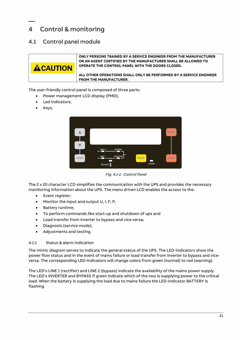
The user-friendly control panel is composed of three parts:
• Power management LCD display (PMD);
• Led indicators;
• Keys.
Fig. 4.1-1: Control Panel
The 2 x 20 character LCD simplifies the communication with the UPS and provides the necessary
monitoring information about the UPS. The menu driven LCD enables the access to the:
• Event register;
• Monitor the input and output U, I, F, P,
• Battery runtime;
• To perform commands like start-up and shutdown of ups and
• Load transfer from inverter to bypass and vice-versa;
• Diagnosis (service mode);
• Adjustments and testing.
4.1.1 Status & alarm indication
The mimic diagram serves to indicate the general status of the UPS. The LED-indicators show the
power flow status and in the event of mains failure or load transfer from inverter to bypass and vice-
versa. The corresponding LED-indicators will change colors from green (normal) to red (warning).
The LED’s LINE 1 (rectifier) and LINE 2 (bypass) indicate the availability of the mains power supply.
The LED’s INVERTER and BYPASS if green indicate which of the two is supplying power to the critical
load. When the battery is supplying the load due to mains failure the LED-indicator BATTERY is
flashing.
22
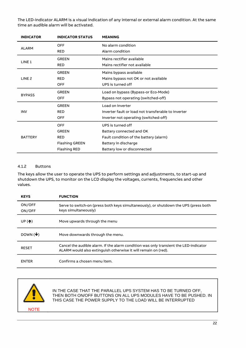
The LED-indicator ALARM is a visual indication of any internal or external alarm condition. At the same
time an audible alarm will be activated.
INDICATOR INDICATOR STATUS MEANING
ALARM OFF
RED
No alarm condition
Alarm condition
LINE 1 GREEN
RED
Mains rectifier available
Mains rectifier not available
LINE 2
GREEN
RED
OFF
Mains bypass available
Mains bypass not OK or not available
UPS is turned off
BYPASS GREEN
OFF
Load on bypass (Bypass-or Eco-Mode)
Bypass not operating (switched-off)
INV
GREEN
RED
OFF
Load on inverter
Inverter fault or load not transferable to inverter
Inverter not operating (switched-off)
BATTERY
OFF
GREEN
RED
Flashing GREEN
Flashing RED
UPS is turned off
Battery connected and OK
Fault condition of the battery (alarm)
Battery in discharge
Battery low or disconnected
4.1.2 Buttons
The keys allow the user to operate the UPS to perform settings and adjustments, to start-up and
shutdown the UPS, to monitor on the LCD display the voltages, currents, frequencies and other
values.
KEYS FUNCTION
ON/OFF
ON/OFF
Serve to switch-on (press both keys simultaneously), or shutdown the UPS (press both
keys simultaneously)
UP () Move upwards through the menu
DOWN () Move downwards through the menu.
RESET Cancel the audible alarm. If the alarm condition was only transient the LED-indicator
ALARM would also extinguish otherwise it will remain on (red).
ENTER Confirms a chosen menu item.
NOTE
IN THE CASE THAT THE PARALLEL UPS SYSTEM HAS TO BE TURNED OFF, THEN BOTH ON/OFF BUTTONS ON ALL UPS MODULES HAVE TO BE PUSHED. IN THIS CASE THE POWER SUPPLY TO THE LOAD WILL BE INTERRUPTED
23
4.2 LCD description
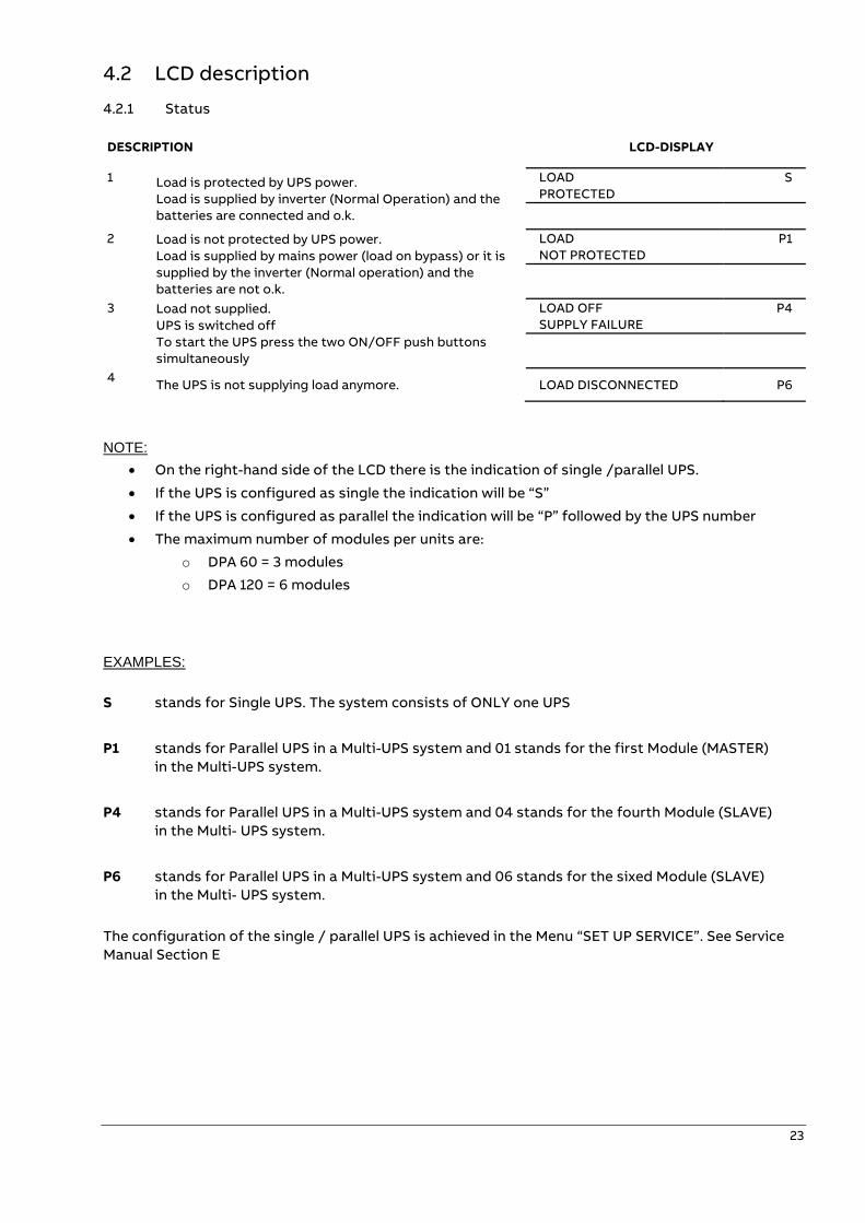
4.2.1 Status
DESCRIPTION LCD-DISPLAY
1 Load is protected by UPS power.
Load is supplied by inverter (Normal Operation) and the
batteries are connected and o.k.
LOAD
PROTECTED
S
2 Load is not protected by UPS power.
Load is supplied by mains power (load on bypass) or it is
supplied by the inverter (Normal operation) and the
batteries are not o.k.
LOAD
NOT PROTECTED
P1
3 Load not supplied.
UPS is switched off
To start the UPS press the two ON/OFF push buttons
simultaneously
LOAD OFF
SUPPLY FAILURE
P4
4 The UPS is not supplying load anymore. LOAD DISCONNECTED P6
NOTE:
• On the right-hand side of the LCD there is the indication of single /parallel UPS.
• If the UPS is configured as single the indication will be “S”
• If the UPS is configured as parallel the indication will be “P” followed by the UPS number
• The maximum number of modules per units are:
o DPA 60 = 3 modules
o DPA 120 = 6 modules
EXAMPLES:
S stands for Single UPS. The system consists of ONLY one UPS
P1 stands for Parallel UPS in a Multi-UPS system and 01 stands for the first Module (MASTER)
in the Multi-UPS system.
P4 stands for Parallel UPS in a Multi-UPS system and 04 stands for the fourth Module (SLAVE)
in the Multi- UPS system.
P6 stands for Parallel UPS in a Multi-UPS system and 06 stands for the sixed Module (SLAVE)
in the Multi- UPS system.
The configuration of the single / parallel UPS is achieved in the Menu “SET UP SERVICE”. See Service
Manual Section E
24
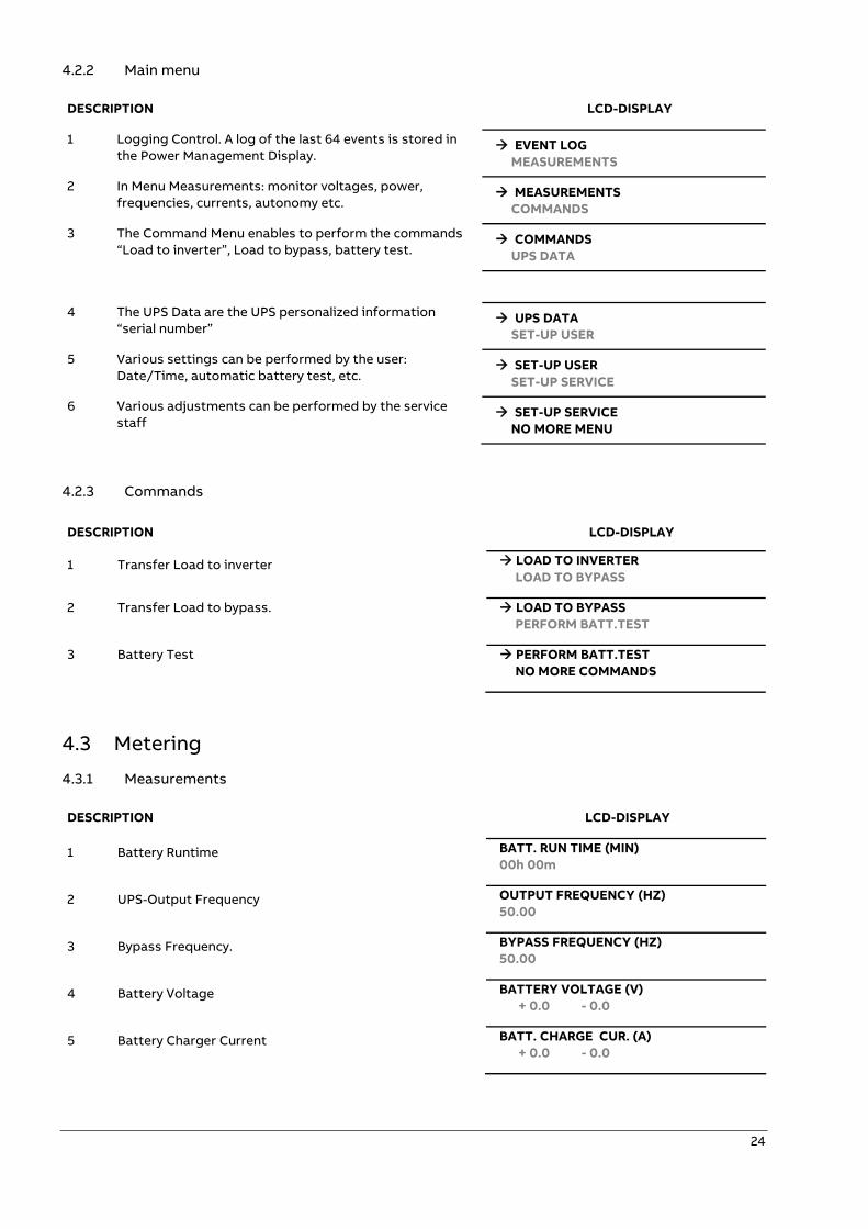
4.2.2 Main menu
DESCRIPTION LCD-DISPLAY
1 Logging Control. A log of the last 64 events is stored in
the Power Management Display. → EVENT LOG
MEASUREMENTS
2 In Menu Measurements: monitor voltages, power,
frequencies, currents, autonomy etc. → MEASUREMENTS
COMMANDS
3 The Command Menu enables to perform the commands
“Load to inverter”, Load to bypass, battery test. → COMMANDS
UPS DATA
4 The UPS Data are the UPS personalized information
“serial number” → UPS DATA
SET-UP USER
5 Various settings can be performed by the user:
Date/Time, automatic battery test, etc. → SET-UP USER
SET-UP SERVICE
6 Various adjustments can be performed by the service
staff → SET-UP SERVICE
NO MORE MENU
4.2.3 Commands
DESCRIPTION LCD-DISPLAY
1 Transfer Load to inverter → LOAD TO INVERTER
LOAD TO BYPASS
2 Transfer Load to bypass. → LOAD TO BYPASS
PERFORM BATT.TEST
3 Battery Test → PERFORM BATT.TEST
NO MORE COMMANDS
4.3 Metering
4.3.1 Measurements
DESCRIPTION LCD-DISPLAY
1 Battery Runtime BATT. RUN TIME (MIN)
00h 00m
2 UPS-Output Frequency OUTPUT FREQUENCY (HZ)
50.00
3 Bypass Frequency. BYPASS FREQUENCY (HZ)
50.00
4 Battery Voltage BATTERY VOLTAGE (V)
+ 0.0 - 0.0
5 Battery Charger Current BATT. CHARGE CUR. (A)
+ 0.0 - 0.0
25
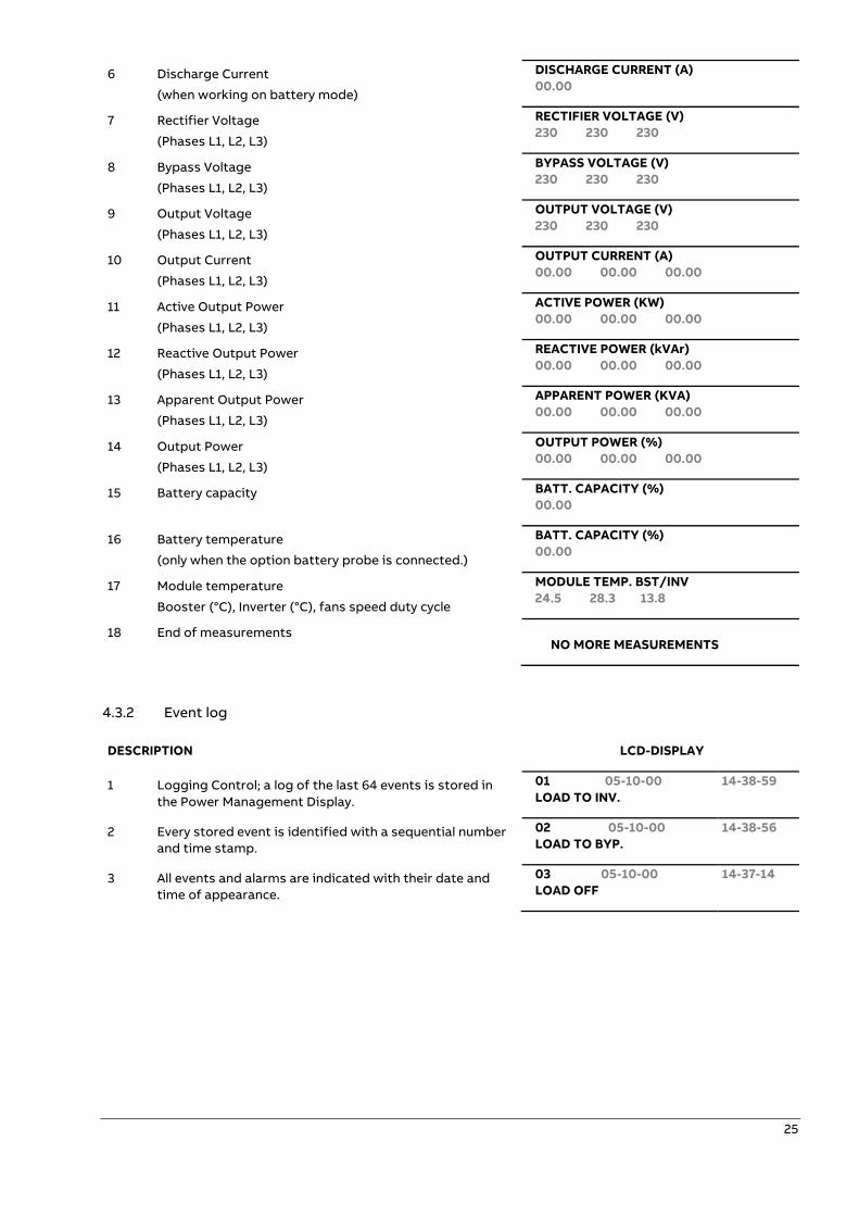
6 Discharge Current
(when working on battery mode)
DISCHARGE CURRENT (A)
00.00
7 Rectifier Voltage
(Phases L1, L2, L3)
RECTIFIER VOLTAGE (V)
230 230 230
8 Bypass Voltage
(Phases L1, L2, L3)
BYPASS VOLTAGE (V)
230 230 230
9 Output Voltage
(Phases L1, L2, L3)
OUTPUT VOLTAGE (V)
230 230 230
10 Output Current
(Phases L1, L2, L3)
OUTPUT CURRENT (A)
00.00 00.00 00.00
11 Active Output Power
(Phases L1, L2, L3)
ACTIVE POWER (KW)
00.00 00.00 00.00
12 Reactive Output Power
(Phases L1, L2, L3)
REACTIVE POWER (kVAr)
00.00 00.00 00.00
13 Apparent Output Power
(Phases L1, L2, L3)
APPARENT POWER (KVA)
00.00 00.00 00.00
14 Output Power
(Phases L1, L2, L3)
OUTPUT POWER (%)
00.00 00.00 00.00
15 Battery capacity BATT. CAPACITY (%)
00.00
16 Battery temperature
(only when the option battery probe is connected.)
BATT. CAPACITY (%)
00.00
17 Module temperature
Booster (°C), Inverter (°C), fans speed duty cycle
MODULE TEMP. BST/INV
24.5 28.3 13.8
18 End of measurements
NO MORE MEASUREMENTS
4.3.2 Event log
DESCRIPTION LCD-DISPLAY
1 Logging Control; a log of the last 64 events is stored in
the Power Management Display.
01 05-10-00
LOAD TO INV.
14-38-59
2 Every stored event is identified with a sequential number
and time stamp.
02 05-10-00
LOAD TO BYP.
14-38-56
3 All events and alarms are indicated with their date and
time of appearance.
03 05-10-00
LOAD OFF
14-37-14
26
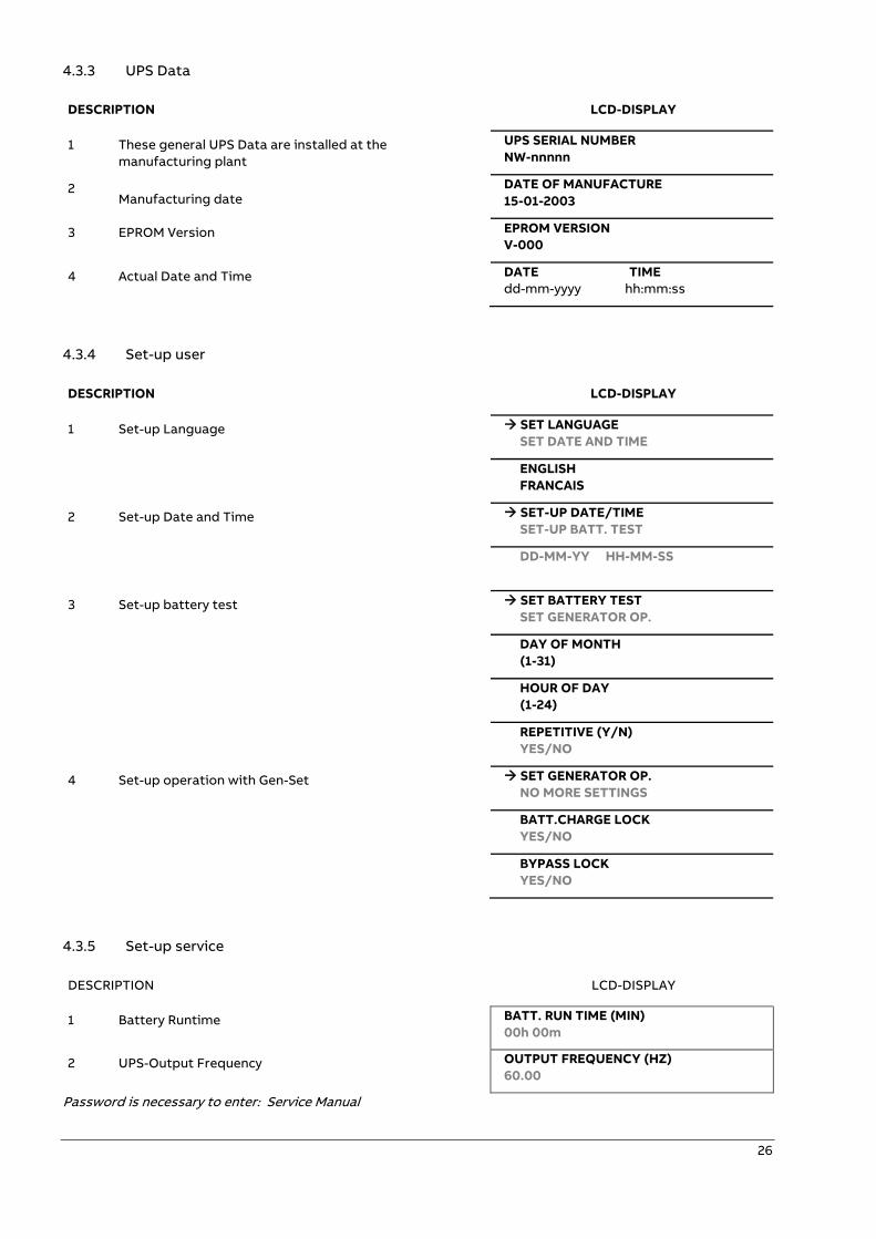
4.3.3 UPS Data
DESCRIPTION LCD-DISPLAY
1 These general UPS Data are installed at the
manufacturing plant
UPS SERIAL NUMBER
NW-nnnnn
2 Manufacturing date
DATE OF MANUFACTURE
15-01-2003
3 EPROM Version EPROM VERSION
V-000
4 Actual Date and Time DATE TIME
dd-mm-yyyy hh:mm:ss
4.3.4 Set-up user
DESCRIPTION LCD-DISPLAY
1 Set-up Language → SET LANGUAGE
SET DATE AND TIME
ENGLISH
FRANCAIS
2 Set-up Date and Time → SET-UP DATE/TIME
SET-UP BATT. TEST
DD-MM-YY HH-MM-SS
3 Set-up battery test → SET BATTERY TEST
SET GENERATOR OP.
DAY OF MONTH
(1-31)
HOUR OF DAY
(1-24)
REPETITIVE (Y/N)
YES/NO
4 Set-up operation with Gen-Set → SET GENERATOR OP.
NO MORE SETTINGS
BATT.CHARGE LOCK
YES/NO
BYPASS LOCK
YES/NO
4.3.5 Set-up service
DESCRIPTION LCD-DISPLAY
1 Battery Runtime BATT. RUN TIME (MIN)
00h 00m
2 UPS-Output Frequency OUTPUT FREQUENCY (HZ)
60.00
Password is necessary to enter: Service Manual
27
—
Installation guide
5 Maintenance & troubleshooting
WARNING!
THE OPERATIONS DESCRIBED IN THIS CHAPTER MUST BE PERFORMED BY A SERVICE ENGINEER FROM THE MANUFACTURER OR FROM AN AGENT CERTIFIED BY THE MANUFACTURER.
5.1 General maintenance
5.1.1 User responsibilities
There are no parts within the UPS which need to be serviced by the user, so the maintenance
responsibilities of the user are zero. To maximize the useful working life and reliability of the UPS and
its batteries, the environment in which the UPS operates should be kept cool 68°F – 77°F [20°C - 25°C],
dry, dust free and vibration free. The batteries should be hold fully charged.
5.1.2 Preventive maintenance
The UPS system needs a regular and constant maintenance (preventive inspections) at least once a
year, even during the warranty period.
Please refer to your authorized service partner for the recommended maintenance plan (including the
specific scheduled replacement of fans and power capacitors). Performing regular and preventive
maintenance not only keeps the performance stable and extends the life of the equipment, but also
decreases the risk of failure. In case these activities not performed, the correct functioning of the
equipment may be affected.
Maintenance inspections are essential to ensure a correct functionality and reliability of the UPS
system. When the UPS is commissioned, the commissioning field service engineer will attach a service
record book to the front of the UPS, and this will be used to record the full service history of the UPS.
During maintenance the field service engineer might carry out some or all of following checks:
• Status and function check of UPS and batteries
• UPS and batteries visual inspection (dust, mechanical damages)
• Visual inspection of screws and cable connections
• Check of air ventilation and room temperature
• Check the operation and function (commutations, remote monitoring and Signaling)
• Current, voltage and frequencies measures
• Measure and record the current load conditions
• Check the load sharing (only in parallel systems)
• Battery voltage check
• Battery discharge test
• Check transfer of the load from UPS to mains operation via static bypass
• Unit cleaning
28
5.1.3 Deep battery test
The battery test takes approximately 3 minutes and should be performed only if:
• There are no alarm conditions
• The battery is fully charged
• Mains are present.
The battery testing can be carried out independently of the operation mode (OFF-LINE or ON-LINE)
and whether or not the load is connected. The battery test procedure can be performed from the UPS
display, in the service setup mode.
5.1.4 Battery maintenance, disposal and recycling
Battery maintenance shall be done by a certified Service
Partner.
To ensure an optimum operation of the UPS system and
a continuous and efficient protection of the connected
load it is recommended to check the batteries every 12
months.
Batteries contain dangerous substances that will harm
the environment if thrown away. If you change the
batteries yourself, call qualified organizations for battery
disposal and recycling.
Fig. 6.1.4-1: Battery maintenance, disposal and recycling
5.2 Troubleshooting
5.2.1 Alarms
In the event of an alarm condition the red LED-Indicator “Alarm” and the audible alarm will turn on.
In this case proceed as follows:
1. Silence the audible alarm by pressing the button "Reset".
2. Identify the cause of the alarm condition by means of the EVENT LOG in the MAIN menu.
3. In case of doubts please contact the nearest Service center.
4. Fault identification and troubleshooting information is provided on the following pages.
5.2.2 Menu, commands, event log and measurements
In section 4 there is a detailed description of the Menu, Commands, Event Log and Measurements
that can be operated and displayed on the LCD. The List of Alarms and Messages are shown below.
29
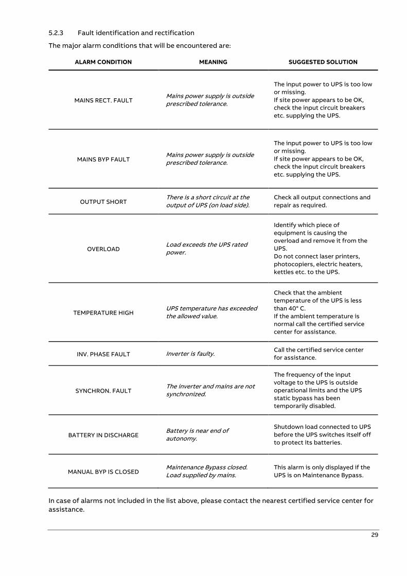
5.2.3 Fault identification and rectification
The major alarm conditions that will be encountered are:
ALARM CONDITION MEANING SUGGESTED SOLUTION
MAINS RECT. FAULT Mains power supply is outside prescribed tolerance.
The input power to UPS is too low
or missing.
If site power appears to be OK,
check the input circuit breakers
etc. supplying the UPS.
MAINS BYP FAULT Mains power supply is outside prescribed tolerance.
The input power to UPS is too low
or missing.
If site power appears to be OK,
check the input circuit breakers
etc. supplying the UPS.
OUTPUT SHORT There is a short circuit at the output of UPS (on load side).
Check all output connections and
repair as required.
OVERLOAD Load exceeds the UPS rated power.
Identify which piece of
equipment is causing the
overload and remove it from the
UPS.
Do not connect laser printers,
photocopiers, electric heaters,
kettles etc. to the UPS.
TEMPERATURE HIGH UPS temperature has exceeded the allowed value.
Check that the ambient
temperature of the UPS is less
than 40° C.
If the ambient temperature is
normal call the certified service
center for assistance.
INV. PHASE FAULT Inverter is faulty. Call the certified service center
for assistance.
SYNCHRON. FAULT The inverter and mains are not synchronized.
The frequency of the input
voltage to the UPS is outside
operational limits and the UPS
static bypass has been
temporarily disabled.
BATTERY IN DISCHARGE Battery is near end of autonomy.
Shutdown load connected to UPS
before the UPS switches itself off
to protect its batteries.
MANUAL BYP IS CLOSED Maintenance Bypass closed. Load supplied by mains.
This alarm is only displayed if the
UPS is on Maintenance Bypass.
In case of alarms not included in the list above, please contact the nearest certified service center for
assistance.
30
—
6 Packing, transportation & storage
This chapter contains all the necessary information for the correct packing, transportation and
unpacking of the UPS.
NOTE!
IF THE UPS IS NOT IMMEDIATELY INSTALLED THE FOLLOWING GUIDELINES MUST BE
FOLLOWED:
TRANSPORT:
UPS CABINETS AND/OR BATTERY CABINET CAN FALL OVER. USE THE SHIPPING BRACKETS
ON THE REAR AND FRONT TO SECURE THE CABINETS. DO NOT TILT THEM MORE THAN 10°
FROM VERTICAL, OTHERWISE CABINETS MAY TIP OVER.
POTENTIAL DANGERS:
- TILTING THE CABINET MIGHT DAMAGE THE SYSTEM AND THEREFORE SHOULD NO
LONGER BE CONNECTED TO THE MAINS.
- WEIGHT OF THE UPS SYSTEM COULD CAUSE SERIOUS INJURIES TO PERSONS OR
ANYTHING IN THE SURROUNDING AREA.
STORAGE:
- THE UPS SHOULD BE STORED IN THE ORIGINAL PACKING AND SHIPPING CARTON
- THE RECOMMENDED STORING TEMPERATURE FOR THE UPS SYSTEM AND BATTERIES
IS BETWEEN 68°F – 77°F [20°C – 25°C].
INDOOR AREA THAT IS RELATIVELY FREE OF CONDUCTIVE CONTAMINANTS
- THE UPS SYSTEM AND THE BATTERY SETS MUST BE PROTECTED FROM HUMIDITY <
95% (NON-CONDENSING)
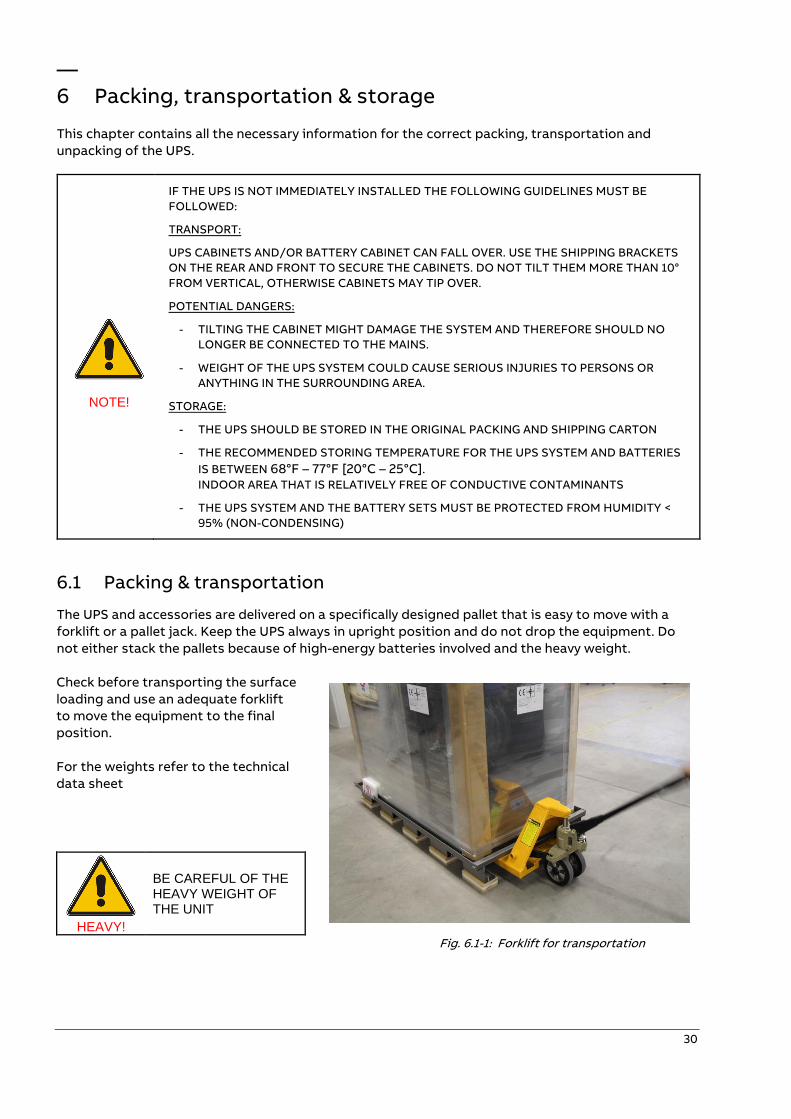
6.1 Packing & transportation
The UPS and accessories are delivered on a specifically designed pallet that is easy to move with a
forklift or a pallet jack. Keep the UPS always in upright position and do not drop the equipment. Do
not either stack the pallets because of high-energy batteries involved and the heavy weight.
Check before transporting the surface
loading and use an adequate forklift
to move the equipment to the final
position.
For the weights refer to the technical
data sheet
HEAVY!
BE CAREFUL OF THE HEAVY WEIGHT OF THE UNIT
Fig. 6.1-1: Forklift for transportation
31
6.2 Unpacking
Upon receiving the goods, make sure that they correspond to the material indicated in the delivery
note.
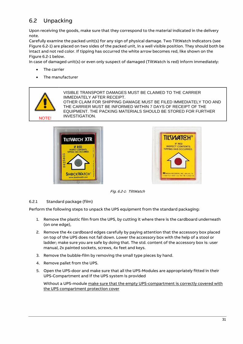
Carefully examine the packed unit(s) for any sign of physical damage. Two TiltWatch indicators (see
Figure 6.2-1) are placed on two sides of the packed unit, in a well visible position. They should both be
intact and not red color. If tipping has occurred the white arrow becomes red, like shown on the
Figure 6.2-1 below.
In case of damaged unit(s) or even only suspect of damaged (TiltWatch is red) inform immediately:
• The carrier
• The manufacturer
NOTE!
VISIBLE TRANSPORT DAMAGES MUST BE CLAIMED TO THE CARRIER IMMEDIATELY AFTER RECEIPT. OTHER CLAIM FOR SHIPPING DAMAGE MUST BE FILED IMMEDIATELY TOO AND THE CARRIER MUST BE INFORMED WITHIN 7 DAYS OF RECEIPT OF THE EQUIPMENT. THE PACKING MATERIALS SHOULD BE STORED FOR FURTHER INVESTIGATION.
Fig. 6.2-1: TiltWatch
6.2.1 Standard package (film)
Perform the following steps to unpack the UPS equipment from the standard packaging:
1. Remove the plastic film from the UPS, by cutting it where there is the cardboard underneath
(on one edge),
2. Remove the 4x cardboard edges carefully by paying attention that the accessory box placed
on top of the UPS does not fall down. Lower the accessory box with the help of a stool or
ladder; make sure you are safe by doing that. The std. content of the accessory box is: user
manual, 2x painted sockets, screws, 4x feet and keys.
3. Remove the bubble-film by removing the small type pieces by hand.
4. Remove pallet from the UPS.
5. Open the UPS-door and make sure that all the UPS-Modules are appropriately fitted in their
UPS-Compartment and if the UPS system is provided
Without a UPS-module make sure that the empty UPS-compartment is correctly covered with
the UPS compartment protection cover
32
6.2.2 Sea freight light package (cartboard box)
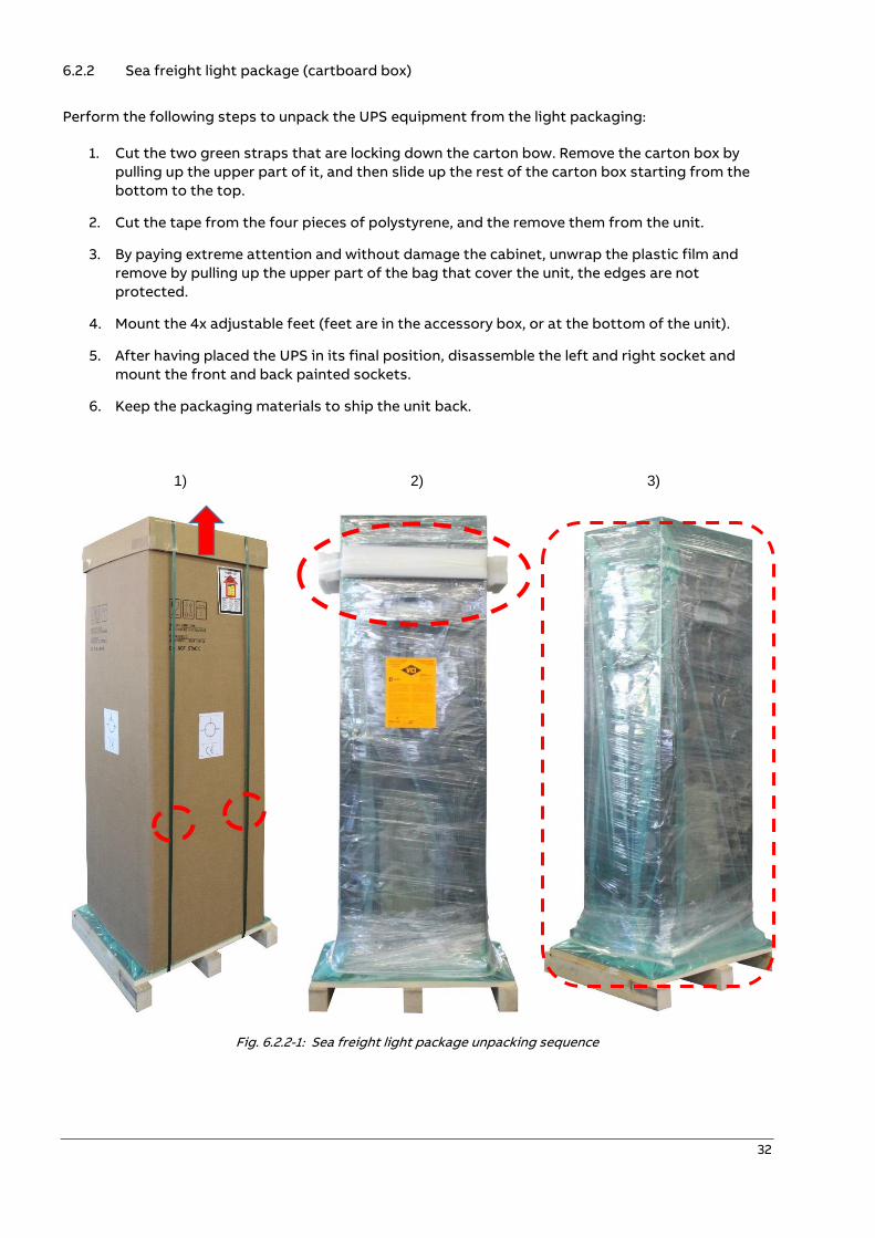
Perform the following steps to unpack the UPS equipment from the light packaging:
1. Cut the two green straps that are locking down the carton bow. Remove the carton box by
pulling up the upper part of it, and then slide up the rest of the carton box starting from the
bottom to the top.
2. Cut the tape from the four pieces of polystyrene, and the remove them from the unit.
3. By paying extreme attention and without damage the cabinet, unwrap the plastic film and
remove by pulling up the upper part of the bag that cover the unit, the edges are not
protected.
4. Mount the 4x adjustable feet (feet are in the accessory box, or at the bottom of the unit).
5. After having placed the UPS in its final position, disassemble the left and right socket and
mount the front and back painted sockets.
6. Keep the packaging materials to ship the unit back.
1) 2) 3)
Fig. 6.2.2-1: Sea freight light package unpacking sequence
33
6.2.3 Sea freight cases (wooden box)
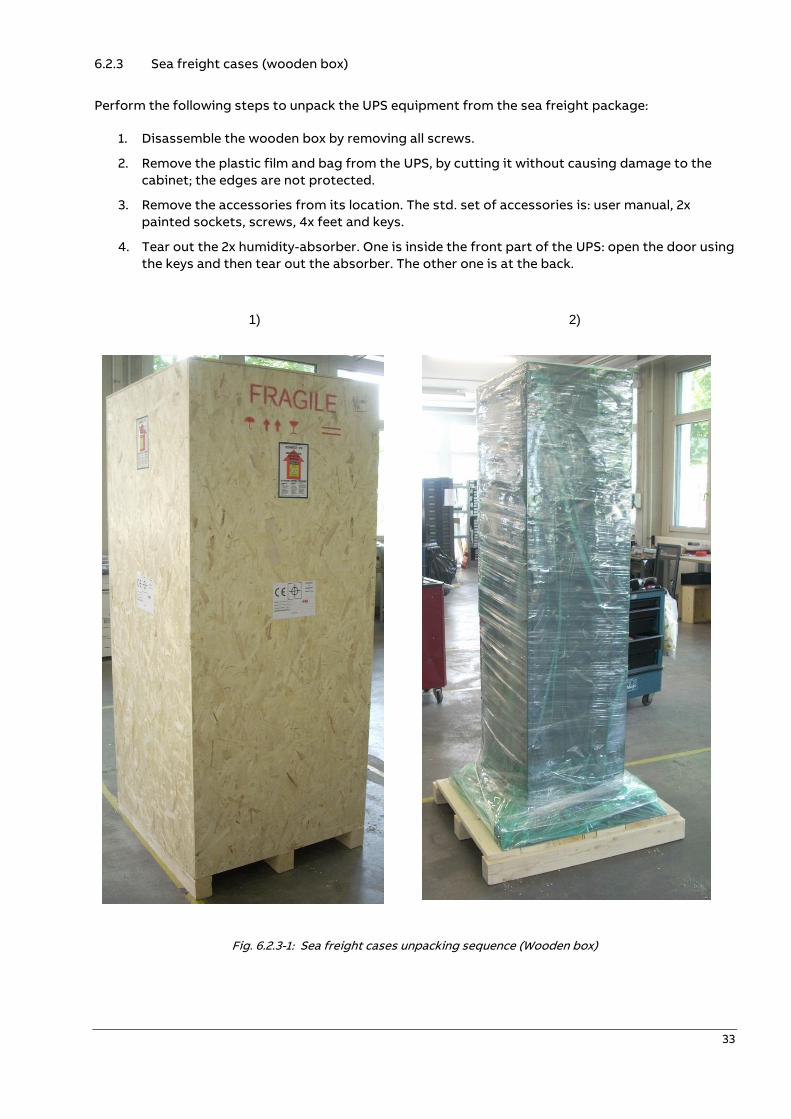
Perform the following steps to unpack the UPS equipment from the sea freight package:
1. Disassemble the wooden box by removing all screws.
2. Remove the plastic film and bag from the UPS, by cutting it without causing damage to the
cabinet; the edges are not protected.
3. Remove the accessories from its location. The std. set of accessories is: user manual, 2x
painted sockets, screws, 4x feet and keys.
4. Tear out the 2x humidity-absorber. One is inside the front part of the UPS: open the door using
the keys and then tear out the absorber. The other one is at the back.
1) 2)
Fig. 6.2.3-1: Sea freight cases unpacking sequence (Wooden box)
34
6.3 Storage
6.3.1 UPS
If you plan to store the UPS prior to use, keep the UPS unpacked in a dry, clean and cool storage room
with an ambient temperature between 68°F – 77°F [20°C – 25°C] and humidity of less than 95% non-
condensing.
If the packing container is removed protect the UPS from dust.
NOTE!
THE UPS SYSTEM, THE BATTERY CABINET AND THE BATTERIES ARE HEAVY AND MAY TIP DURING TRANSPORTATION CAUSING SERIOUS INJURY IF UNPACKING INSTRUCTIONS ARE NOT CLOSELY FOLLOWED.
6.3.2 Batteries
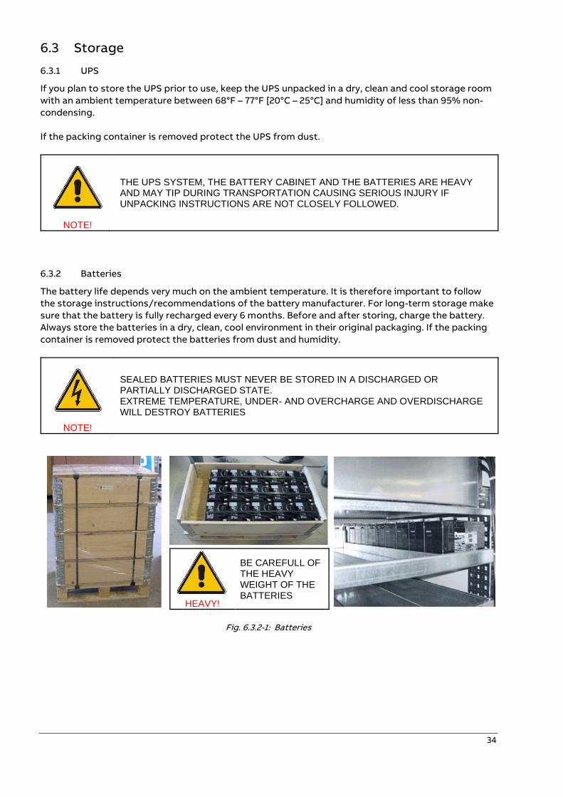
The battery life depends very much on the ambient temperature. It is therefore important to follow
the storage instructions/recommendations of the battery manufacturer. For long-term storage make
sure that the battery is fully recharged every 6 months. Before and after storing, charge the battery.
Always store the batteries in a dry, clean, cool environment in their original packaging. If the packing
container is removed protect the batteries from dust and humidity.
NOTE!
SEALED BATTERIES MUST NEVER BE STORED IN A DISCHARGED OR PARTIALLY DISCHARGED STATE. EXTREME TEMPERATURE, UNDER- AND OVERCHARGE AND OVERDISCHARGE WILL DESTROY BATTERIES
HEAVY!
BE CAREFULL OF THE HEAVY WEIGHT OF THE BATTERIES
Fig. 6.3.2-1: Batteries
35
—
7 Installation
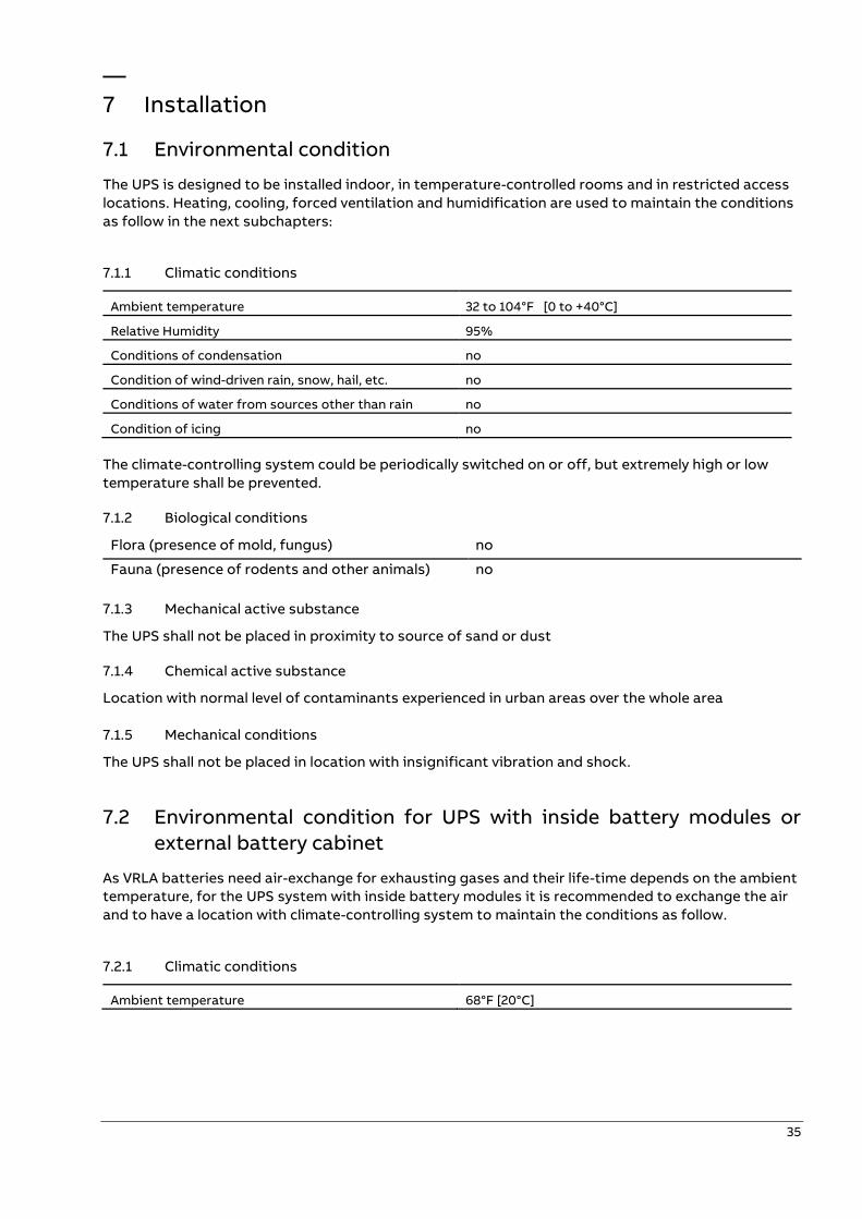
7.1 Environmental condition
The UPS is designed to be installed indoor, in temperature-controlled rooms and in restricted access
locations. Heating, cooling, forced ventilation and humidification are used to maintain the conditions
as follow in the next subchapters:
7.1.1 Climatic conditions
Ambient temperature 32 to 104°F [0 to +40°C]
Relative Humidity 95%
Conditions of condensation no
Condition of wind-driven rain, snow, hail, etc. no
Conditions of water from sources other than rain no
Condition of icing no
The climate-controlling system could be periodically switched on or off, but extremely high or low
temperature shall be prevented.
7.1.2 Biological conditions
Flora (presence of mold, fungus) no
Fauna (presence of rodents and other animals) no
7.1.3 Mechanical active substance
The UPS shall not be placed in proximity to source of sand or dust
7.1.4 Chemical active substance
Location with normal level of contaminants experienced in urban areas over the whole area
7.1.5 Mechanical conditions
The UPS shall not be placed in location with insignificant vibration and shock.
7.2 Environmental condition for UPS with inside battery modules or
external battery cabinet
As VRLA batteries need air-exchange for exhausting gases and their life-time depends on the ambient
temperature, for the UPS system with inside battery modules it is recommended to exchange the air
and to have a location with climate-controlling system to maintain the conditions as follow.
7.2.1 Climatic conditions
Ambient temperature 68°F [20°C]
36
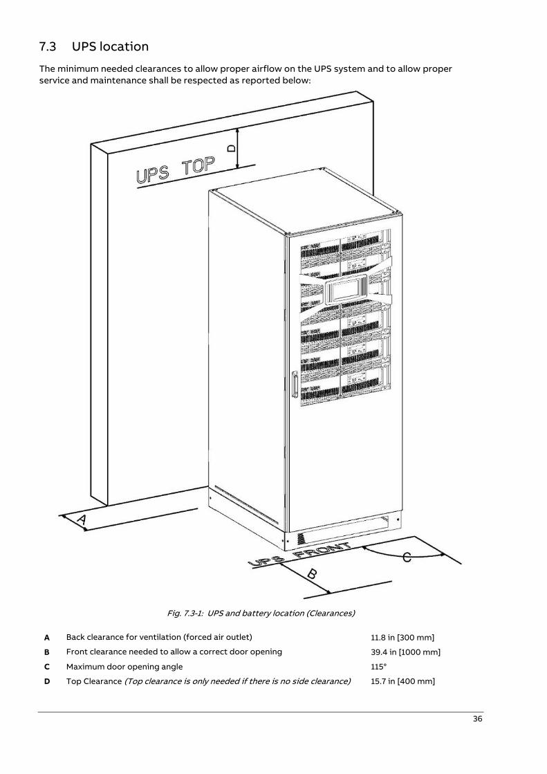
7.3 UPS location
The minimum needed clearances to allow proper airflow on the UPS system and to allow proper
service and maintenance shall be respected as reported below:
Fig. 7.3-1: UPS and battery location (Clearances)
A Back clearance for ventilation (forced air outlet) 11.8 in [300 mm]
B Front clearance needed to allow a correct door opening 39.4 in [1000 mm]
C Maximum door opening angle 115°
D Top Clearance (Top clearance is only needed if there is no side clearance) 15.7 in [400 mm]
37
Battery cabinet location
In most of the cases the battery cabinet is positioned at the side of the UPS cabinet (unless the UPS
cabinet required side access) and takes advantage of the seam clearances. The minimum needed
clearances of the battery cabinet depend on the design of the cabinet (especially the openings). As
VRLA batteries need natural ventilation, it is always recommended to keep a certain clearance from
the openings. How much that clearance needs to be is highly depended on the installation, a good rule
is to keep a minimum of 3.94” [100mm] clearance at the walls with opening.
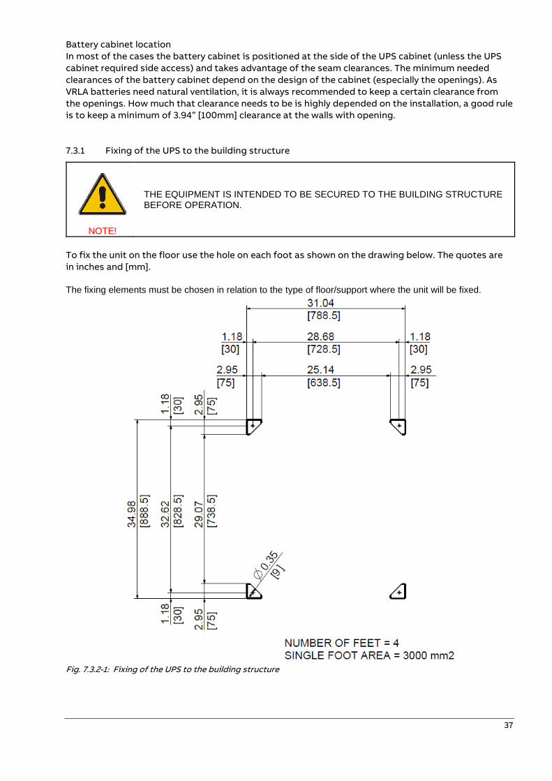
7.3.1 Fixing of the UPS to the building structure
NOTE!
THE EQUIPMENT IS INTENDED TO BE SECURED TO THE BUILDING STRUCTURE BEFORE OPERATION.
To fix the unit on the floor use the hole on each foot as shown on the drawing below. The quotes are
in inches and [mm].
The fixing elements must be chosen in relation to the type of floor/support where the unit will be fixed.
Fig. 7.3.2-1: Fixing of the UPS to the building structure
38
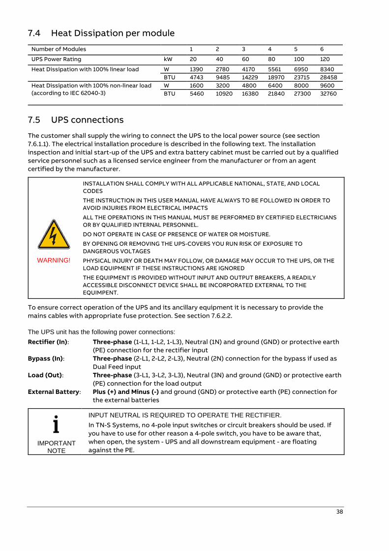
7.4 Heat Dissipation per module
Number of Modules 1 2 3 4 5 6
UPS Power Rating kW 20 40 60 80 100 120
Heat Dissipation with 100% linear load W 1390 2780 4170 5561 6950 8340
BTU 4743 9485 14229 18970 23715 28458
Heat Dissipation with 100% non-linear load
(according to IEC 62040-3)
W 1600 3200 4800 6400 8000 9600
BTU 5460 10920 16380 21840 27300 32760
7.5 UPS connections
The customer shall supply the wiring to connect the UPS to the local power source (see section
7.6.1.1). The electrical installation procedure is described in the following text. The installation
inspection and initial start-up of the UPS and extra battery cabinet must be carried out by a qualified
service personnel such as a licensed service engineer from the manufacturer or from an agent
certified by the manufacturer.
WARNING!
INSTALLATION SHALL COMPLY WITH ALL APPLICABLE NATIONAL, STATE, AND LOCAL
CODES
THE INSTRUCTION IN THIS USER MANUAL HAVE ALWAYS TO BE FOLLOWED IN ORDER TO
AVOID INJURIES FROM ELECTRICAL IMPACTS
ALL THE OPERATIONS IN THIS MANUAL MUST BE PERFORMED BY CERTIFIED ELECTRICIANS
OR BY QUALIFIED INTERNAL PERSONNEL.
DO NOT OPERATE IN CASE OF PRESENCE OF WATER OR MOISTURE.
BY OPENING OR REMOVING THE UPS-COVERS YOU RUN RISK OF EXPOSURE TO
DANGEROUS VOLTAGES
PHYSICAL INJURY OR DEATH MAY FOLLOW, OR DAMAGE MAY OCCUR TO THE UPS, OR THE
LOAD EQUIPMENT IF THESE INSTRUCTIONS ARE IGNORED
THE EQUIPMENT IS PROVIDED WITHOUT INPUT AND OUTPUT BREAKERS, A READILY
ACCESSIBLE DISCONNECT DEVICE SHALL BE INCORPORATED EXTERNAL TO THE
EQUIMPENT.
To ensure correct operation of the UPS and its ancillary equipment it is necessary to provide the
mains cables with appropriate fuse protection. See section 7.6.2.2.
The UPS unit has the following power connections:
Rectifier (In): Three-phase (1-L1, 1-L2, 1-L3), Neutral (1N) and ground (GND) or protective earth
(PE) connection for the rectifier input
Bypass (In): Three-phase (2-L1, 2-L2, 2-L3), Neutral (2N) connection for the bypass if used as
Dual Feed input
Load (Out): Three-phase (3-L1, 3-L2, 3-L3), Neutral (3N) and ground (GND) or protective earth
(PE) connection for the load output
External Battery: Plus (+) and Minus (-) and ground (GND) or protective earth (PE) connection for
the external batteries
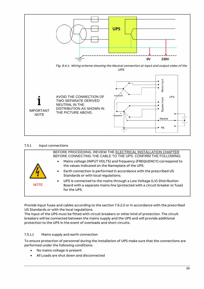
IMPORTANT NOTE
INPUT NEUTRAL IS REQUIRED TO OPERATE THE RECTIFIER.
In TN-S Systems, no 4-pole input switches or circuit breakers should be used. If
you have to use for other reason a 4-pole switch, you have to be aware that,
when open, the system - UPS and all downstream equipment - are floating
against the PE.
39
Fig. 8.4-1: Wiring scheme showing the Neutral connection at input and output sides of the UPS.
IMPORTANT NOTE
AVOID THE CONNECTION OF TWO SEPARATE DERIVED NEUTRAL IN THE DISTRIBUTION AS SHOWN IN THE PICTURE ABOVE.
7.5.1 Input connections
NOTE
BEFORE PROCEEDING, REVIEW THE ELECTRICAL INSTALLATION CHAPTER BEFORE CONNECTING THE CABLE TO THE UPS. CONFIRM THE FOLLOWING:
• Mains voltage (INPUT VOLTS) and frequency (FREQUENCY) correspond to
the values indicated on the Nameplate of the UPS.
• Earth connection is performed in accordance with the prescribed US
Standards or with local regulations;
• UPS is connected to the mains through a Low Voltage (LV)-Distribution
Board with a separate mains line (protected with a circuit breaker or fuse)
for the UPS.
Provide input fuses and cables according to the section 7.6.2.2 or in accordance with the prescribed
US Standards or with the local regulations.
The input of the UPS must be fitted with circuit breakers or other kind of protection. The circuit
breakers will be connected between the mains supply and the UPS and will provide additional
protection to the UPS in the event of overloads and short circuits.
7.5.1.1 Mains supply and earth connection
To ensure protection of personnel during the installation of UPS make sure that the connections are
performed under the following conditions:
• No mains voltage is present
• All Loads are shut down and disconnected
40
• UPS is shut down and voltage-free
• UPS-Module is fitted in its correct position
• Maintenance Bypass IA1 is open and in position OFF;
• Remove Terminal cover of the UPS
• Connect first the ground-wire coming from the Low Voltage-Distribution Board to the
terminal GND (PE).
• Connect the input power cable coming from the Low Voltage-Distribution Board to the
terminals of the UPS shown in section 7.6.1
Keep the
phase
rotation in
clock-wise
sense.
NOTE
INPUT NEUTRAL IS REQUIRED TO OPERATE THE RECTIFIER
Under the connection terminal of the UPS there is a cable-fixing rail to ensure that the cables have
been fastened properly.
NOTE: The UPS is provided with facilities for both single feed (one common input cable for rectifier and
bypass) and dual feed (separate input cable for rectifier and bypass).
7.5.1.2 Single input feed
For proper cable landing locations refer to section 7.6.1.
For single input feed connect the mains input cable to UPS terminal block according to the following
table:
MAINS INPUT CABLE UPS TERMINAL
Phase L1 1-L1
Phase L2 1-L2
Phase L3 1-L3
NEUTRAL 1-N
GROUND (EARTH) GND (PE)
For minimum recommended Input Cable Sections and Fuse Ratings refer to section 7.6.1.1.
Under the connection terminal of the UPS there is a cable-fixing rail to ensure that the cables have
been fastened properly.
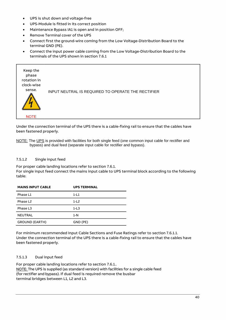
7.5.1.3 Dual input feed
For proper cable landing locations refer to section 7.6.1..
NOTE: The UPS is supplied (as standard version) with facilities for a single cable feed
(for rectifier and bypass). If dual feed is required remove the busbar
terminal bridges between L1, L2 and L3.
41
UPS TERMINAL Rectifier UPS TERMINAL Bypass
1L1 2-L1
1L2 2-L2
1L3 2-L3
1N 2-N
GND (PE)
For dual input feed connect the mains input cables to UPS Terminal, and the according to following
tables:
MAINS INPUT CABLE UPS TERMINAL
Rectifier BYPASS INPUT CABLE
UPS TERMINAL
Bypass
Phase L1 1-L1 Phase L1 2-L1
Phase L2 1-L2 Phase L2 2-L2
Phase L3 1-L3 Phase L3 2-L3
GROUND (EARTH) GND (PE) NEUTRAL 1-N / 2-N
For minimum recommended Input Cable Sections and Fuse Ratings refer to section 7.6.2.2.
Under the connection terminal of the UPS there is a cable-fixing rail to ensure that the cables have
been fastened properly.
7.5.1.4 External Common Battery Connection
For proper cable landing locations refer to section 7.6.1.
For systems configured for external batteries connect the DC input cable to UPS terminal block
according to the following table:
DC INPUT CABLE UPS TERMINAL
DC (+) DC+ BATT
DC (-) DC- BATT
GROUND (EARTH) GND (PE)
For minimum recommended Input Cable Sections and Fuse Ratings refer to section 7.6.2.2.
Under the connection terminal of the UPS there is a cable-fixing rail to ensure that the cables have
been fastened properly.
7.5.1.5 External Separate Battery Connection
For proper cable landing locations refer to section 7.6.4.
For systems configured for external batteries connect the DC input cable to UPS terminal block
according to the following table:
DC INPUT CABLE UPS TERMINAL
DC Source 1 (+) F3-1 (+)
DC Source 2 (+) F3-2 (+)
DC Source 3 (+) F3-3 (+)
42
DC INPUT CABLE UPS TERMINAL
DC Source 1 (-) F3-1 (-)
DC Source 2 (-) F3-2 (-)
DC Source 3 (-) F3-3 (-)
GROUND (EARTH) GND (PE)
For minimum recommended Input Cable Sections and Fuse Ratings refer to section 7.6.1.1.
Under the connection terminal of the UPS there is a cable-fixing rail to ensure that the cables have
been fastened properly.
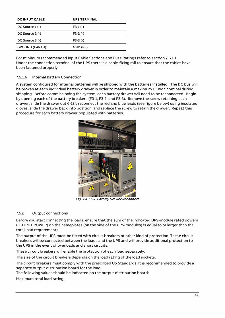
7.5.1.6 Internal Battery Connection
A system configured for internal batteries will be shipped with the batteries installed. The DC bus will
be broken at each individual battery drawer in order to maintain a maximum 120Vdc nominal during
shipping. Before commissioning the system, each battery drawer will need to be reconnected. Begin
by opening each of the battery breakers (F3-1, F3-2, and F3-3). Remove the screw retaining each
drawer, slide the drawer out 6-12”, reconnect the red and blue leads (see figure below) using insulated
gloves, slide the drawer back into position, and replace the screw to retain the drawer. Repeat this
procedure for each battery drawer populated with batteries.
Fig. 7.4.1.6-1: Battery Drawer Reconnect
7.5.2 Output connections
Before you start connecting the loads, ensure that the sum of the indicated UPS-module rated powers
(OUTPUT POWER) on the nameplates (on the side of the UPS-modules) is equal to or larger than the
total load requirements.
The output of the UPS must be fitted with circuit breakers or other kind of protection. These circuit
breakers will be connected between the loads and the UPS and will provide additional protection to
the UPS in the event of overloads and short circuits.
These circuit breakers will enable the protection of each load separately.
The size of the circuit breakers depends on the load rating of the load sockets.
The circuit breakers must comply with the prescribed US Standards. It is recommended to provide a
separate output distribution board for the load.
The following values should be indicated on the output distribution board:
Maximum total load rating;

43
Maximum load rating of the load sockets.
If a common distribution board is used (sockets for Mains and UPS voltage), ensure that on each
socket there is an indication of the applied voltage (“Mains” or “UPS”).
Output power cable ratings should be in accordance with the recommended cable sections and fuses
ratings or in accordance with the prescribed US Standards or with the local regulations.
Under the connection terminal of the UPS there is a cable-fixing rail to ensure that the cables have
been fastened properly.
Ensure that the earthing is performed in accordance with the prescribed US Standards or with the
local regulations.
7.5.2.1 Load connection
To ensure protection of the personnel during the installation of the UPS make sure that the
connections are performed under the following conditions:
No mains voltage is present;
All loads are shut down and disconnected;
PMC is shut down and voltage-free.
Before connecting the output, power cables make sure that:
UPS-Module is fitted in its correct position;
Maintenance bypass is in position OFF;
Remove the terminal cover of the UPS.
Connect the output power cable coming from the LV-Distribution Board to the terminals of the UPS.
44
7.6 Electrical wirings
The customer shall supply the wiring to connect the UPS to the local power source. The installation
inspection and initial start-up of the UPS and extra battery cabinet must be carried out by a qualified
service personnel such as a licensed service engineer from the manufacturer or from an agent
certified by the manufacturer.
NOTE
USE ONLY LISTED TERMINAL LUGS FOR CONNECTION! TERMINALS PART NUMBER 54113 or 54114 ARE SUGGESTED FOR WIRING:
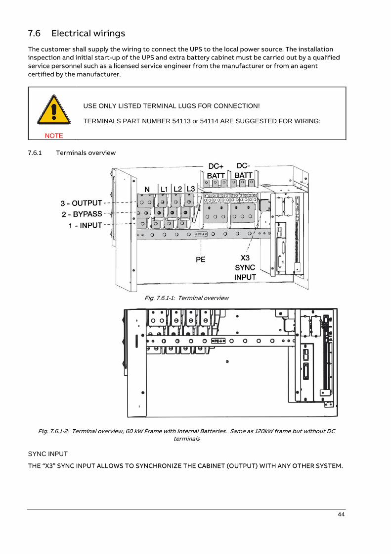
7.6.1 Terminals overview
Fig. 7.6.1-1: Terminal overview
Fig. 7.6.1-2: Terminal overview; 60 kW Frame with Internal Batteries. Same as 120kW frame but without DC
terminals
SYNC INPUT
THE “X3” SYNC INPUT ALLOWS TO SYNCHRONIZE THE CABINET (OUTPUT) WITH ANY OTHER SYSTEM.
45
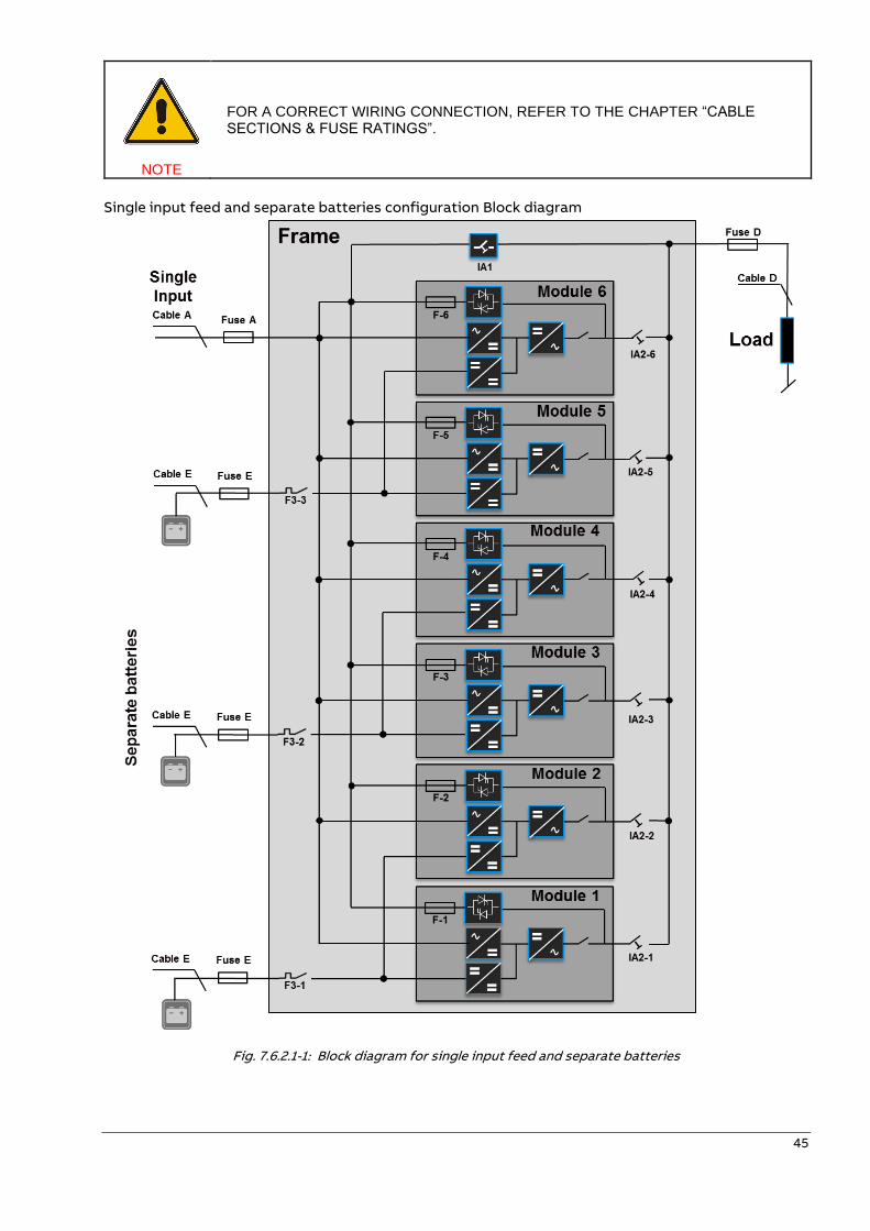
NOTE
FOR A CORRECT WIRING CONNECTION, REFER TO THE CHAPTER “CABLE SECTIONS & FUSE RATINGS”.
Single input feed and separate batteries configuration Block diagram
Fig. 7.6.2.1-1: Block diagram for single input feed and separate batteries
46
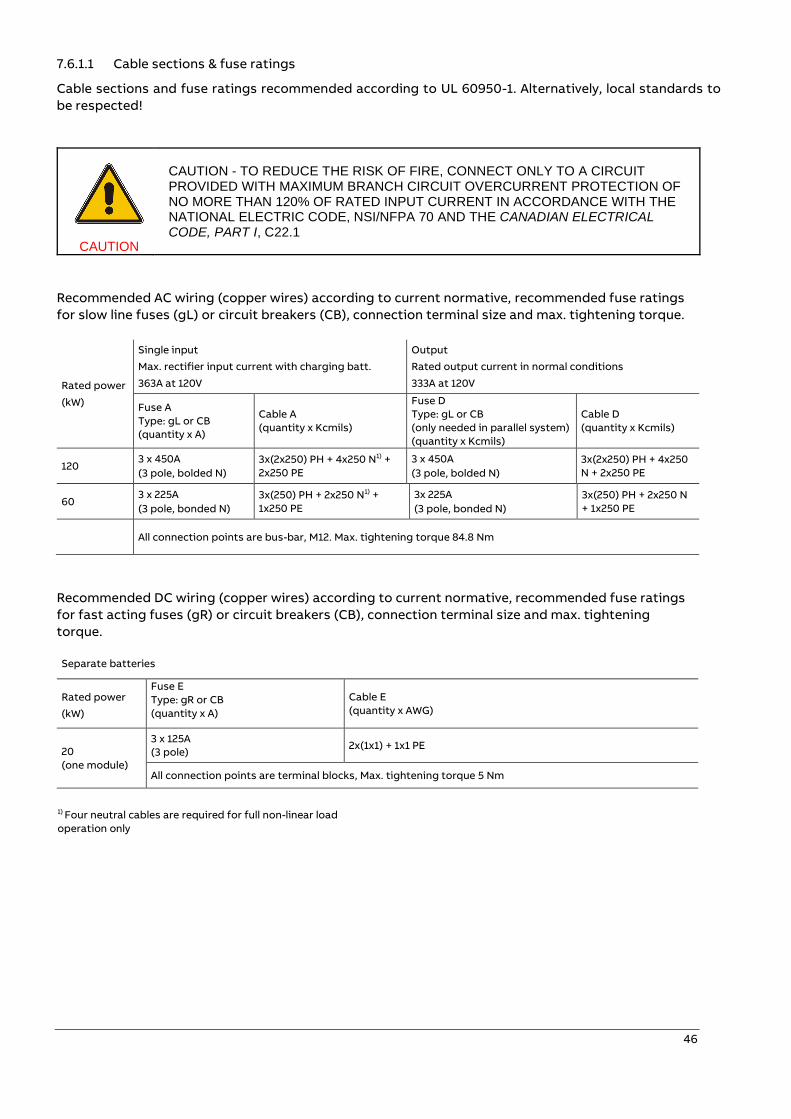
7.6.1.1 Cable sections & fuse ratings
Cable sections and fuse ratings recommended according to UL 60950-1. Alternatively, local standards to
be respected!
CAUTION
CAUTION - TO REDUCE THE RISK OF FIRE, CONNECT ONLY TO A CIRCUIT PROVIDED WITH MAXIMUM BRANCH CIRCUIT OVERCURRENT PROTECTION OF NO MORE THAN 120% OF RATED INPUT CURRENT IN ACCORDANCE WITH THE NATIONAL ELECTRIC CODE, NSI/NFPA 70 AND THE CANADIAN ELECTRICAL CODE, PART I, C22.1
Recommended AC wiring (copper wires) according to current normative, recommended fuse ratings
for slow line fuses (gL) or circuit breakers (CB), connection terminal size and max. tightening torque.
Rated power
(kW)
Single input
Max. rectifier input current with charging batt.
363A at 120V
Output
Rated output current in normal conditions
333A at 120V
Fuse A
Type: gL or CB
(quantity x A)
Cable A
(quantity x Kcmils)
Fuse D
Type: gL or CB
(only needed in parallel system)
(quantity x Kcmils)
Cable D
(quantity x Kcmils)
120 3 x 450A
(3 pole, bolded N)
3x(2x250) PH + 4x250 N1) +
2x250 PE
3 x 450A
(3 pole, bolded N)
3x(2x250) PH + 4x250
N + 2x250 PE
60 3 x 225A
(3 pole, bonded N) 3x(250) PH + 2x250 N1) +
1x250 PE
3x 225A
(3 pole, bonded N)
3x(250) PH + 2x250 N
+ 1x250 PE
All connection points are bus-bar, M12. Max. tightening torque 84.8 Nm
Recommended DC wiring (copper wires) according to current normative, recommended fuse ratings
for fast acting fuses (gR) or circuit breakers (CB), connection terminal size and max. tightening
torque.
Separate batteries
Rated power
(kW)
Fuse E
Type: gR or CB
(quantity x A)
Cable E
(quantity x AWG)
20
(one module)
3 x 125A
(3 pole) 2x(1x1) + 1x1 PE
All connection points are terminal blocks, Max. tightening torque 5 Nm
1) Four neutral cables are required for full non-linear load
operation only
47
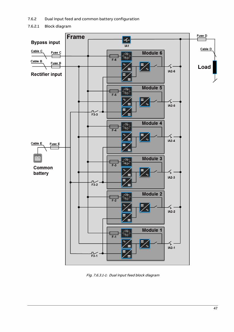
7.6.2 Dual input feed and common battery configuration
7.6.2.1 Block diagram
Fig. 7.6.3.1-1: Dual input feed block diagram
48
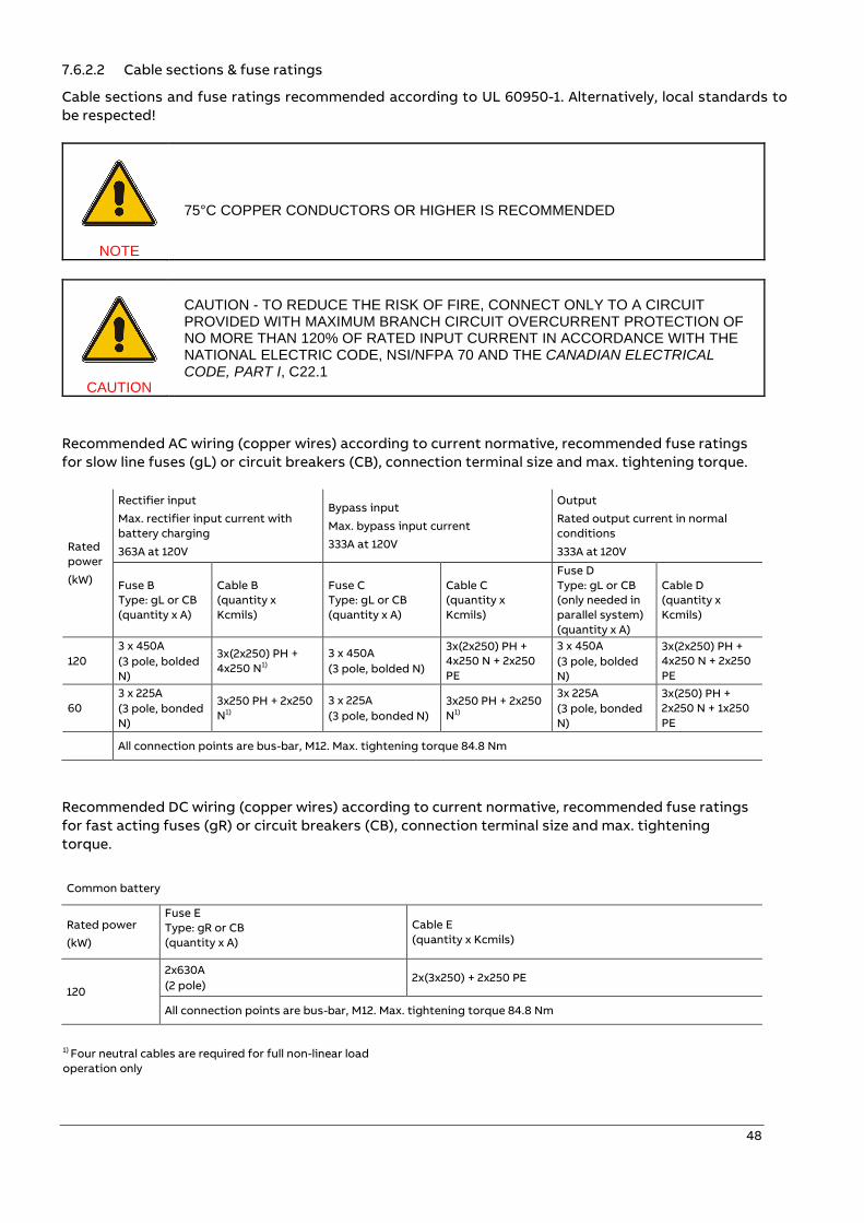
7.6.2.2 Cable sections & fuse ratings
Cable sections and fuse ratings recommended according to UL 60950-1. Alternatively, local standards to
be respected!
NOTE
75°C COPPER CONDUCTORS OR HIGHER IS RECOMMENDED
CAUTION
CAUTION - TO REDUCE THE RISK OF FIRE, CONNECT ONLY TO A CIRCUIT PROVIDED WITH MAXIMUM BRANCH CIRCUIT OVERCURRENT PROTECTION OF NO MORE THAN 120% OF RATED INPUT CURRENT IN ACCORDANCE WITH THE NATIONAL ELECTRIC CODE, NSI/NFPA 70 AND THE CANADIAN ELECTRICAL CODE, PART I, C22.1
Recommended AC wiring (copper wires) according to current normative, recommended fuse ratings
for slow line fuses (gL) or circuit breakers (CB), connection terminal size and max. tightening torque.
Rated
power
(kW)
Rectifier input
Max. rectifier input current with
battery charging
363A at 120V
Bypass input
Max. bypass input current
333A at 120V
Output
Rated output current in normal
conditions
333A at 120V
Fuse B
Type: gL or CB
(quantity x A)
Cable B
(quantity x
Kcmils)
Fuse C
Type: gL or CB
(quantity x A)
Cable C
(quantity x
Kcmils)
Fuse D
Type: gL or CB
(only needed in
parallel system)
(quantity x A)
Cable D
(quantity x
Kcmils)
120
3 x 450A
(3 pole, bolded
N)
3x(2x250) PH +
4x250 N1)
3 x 450A
(3 pole, bolded N)
3x(2x250) PH +
4x250 N + 2x250
PE
3 x 450A
(3 pole, bolded
N)
3x(2x250) PH +
4x250 N + 2x250
PE
60
3 x 225A
(3 pole, bonded
N)
3x250 PH + 2x250
N1)
3 x 225A
(3 pole, bonded N)
3x250 PH + 2x250
N1)
3x 225A
(3 pole, bonded
N)
3x(250) PH +
2x250 N + 1x250
PE
All connection points are bus-bar, M12. Max. tightening torque 84.8 Nm
Recommended DC wiring (copper wires) according to current normative, recommended fuse ratings
for fast acting fuses (gR) or circuit breakers (CB), connection terminal size and max. tightening
torque.
Common battery
Rated power
(kW)
Fuse E
Type: gR or CB
(quantity x A)
Cable E
(quantity x Kcmils)
120
2x630A
(2 pole) 2x(3x250) + 2x250 PE
All connection points are bus-bar, M12. Max. tightening torque 84.8 Nm
1) Four neutral cables are required for full non-linear load
operation only
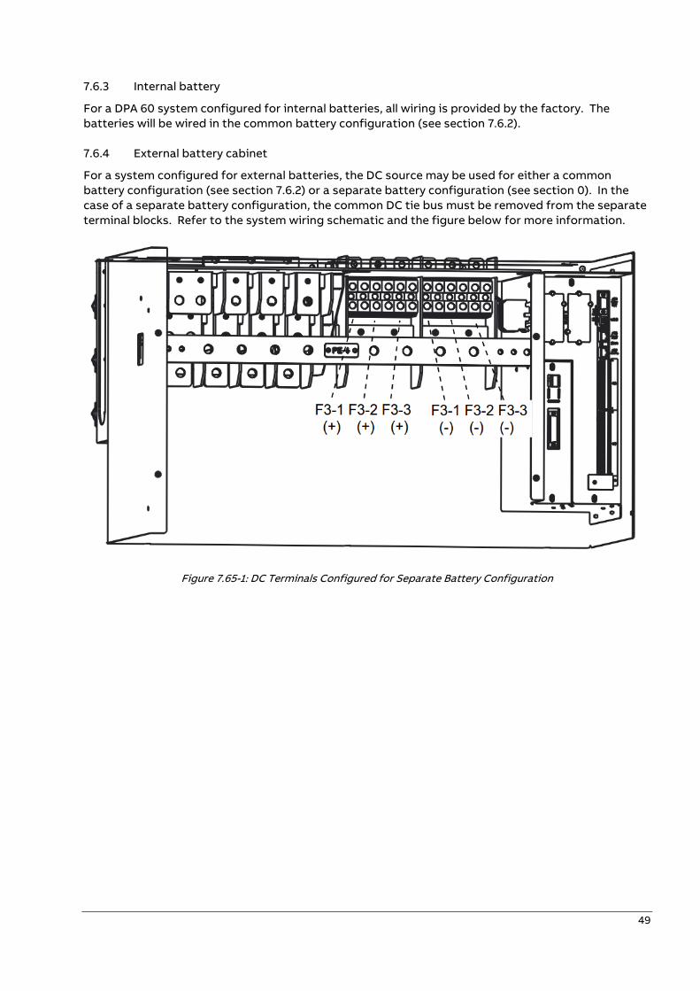
49
7.6.3 Internal battery
For a DPA 60 system configured for internal batteries, all wiring is provided by the factory. The
batteries will be wired in the common battery configuration (see section 7.6.2).
7.6.4 External battery cabinet
For a system configured for external batteries, the DC source may be used for either a common
battery configuration (see section 7.6.2) or a separate battery configuration (see section 0). In the
case of a separate battery configuration, the common DC tie bus must be removed from the separate
terminal blocks. Refer to the system wiring schematic and the figure below for more information.
Figure 7.65-1: DC Terminals Configured for Separate Battery Configuration
50
—
8 Communication interfaces
WARNING!
ALL THE INPUT/OUTPUT PORTS ARE CLASS 2 (SELV CIRCUITS). PLEASE MAINTAIN SECURITY WHEN CONNECTING TO OTHER DEVICES.
The UPS cabinet is provided with communication card which provides the system information
Communication card (next to the distribution):
• Interlock interface X1 (Interlock function)
• Input Interfaces X3 (Phoenix terminals)
• Output Interfaces: X2 DRY PORTs, volt-free contacts (Phoenix
terminals)
• Smart Port JD1 / RS232 Sub D9 / female: Interface (UPS system to computer)
• USB Interface (UPS system to computer)
On the Interface board are located two LED’s:
1. Green LED showing the status of the Interface:
- Fast Blinking: 2 times/sec = Interface is OK
2. Red LED Board Alarm (indicates a possible replacement of
the board)
8.1.1 Customer Interface and DRY PORTs
All the input and output interfaces are connected to phoenix terminals (cable 0.5 mm2).
8.1.1.1 Output Interfaces: Terminal blocks X2 (DRY PORTs)
Provision of signals for the automatic and orderly shutdown of servers, AS400 or Automation building
systems
8.1.1.2 Input interfaces: Terminal blocks X3
Connection of Remote Shutdown facilities, Generator Operation, Customers specials
Refer to the chapter 9.3.1.
8.1.1.3 Interlock interface: Terminal blocks X1
This function allows a secure transfer from inverter (normal operation) to external maintenance
bypass and vice-versa. During normal operation the external bypass is locked in position OFF. Only
when the UPS is/are transferred to static bypass mode, the lock on the external bypass is released
and it possible to switch to position ON. The transfer from maintenance bypass back to normal
operation happens exactly the other way around. The release signal is closed (ON) when the
maintenance bypass is closed and open (OFF) when the maintenance bypass is open locked.
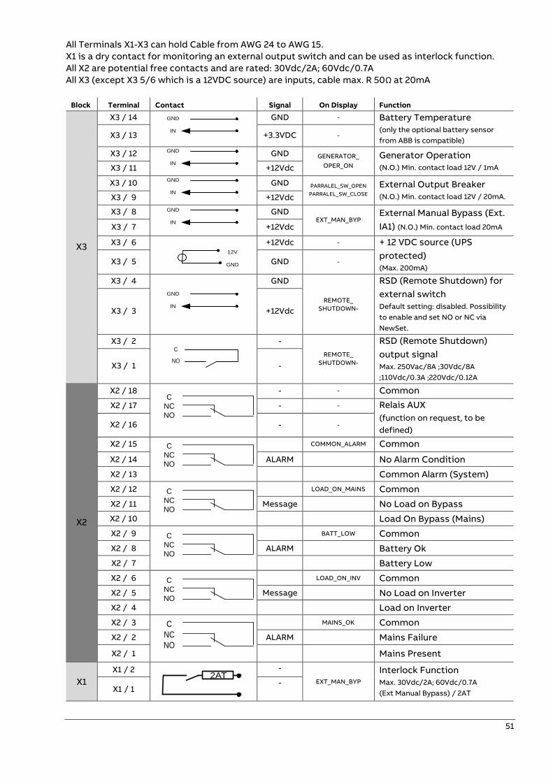
51
All Terminals X1-X3 can hold Cable from AWG 24 to AWG 15.
X1 is a dry contact for monitoring an external output switch and can be used as interlock function.
All X2 are potential free contacts and are rated: 30Vdc/2A; 60Vdc/0.7A
All X3 (except X3 5/6 which is a 12VDC source) are inputs, cable max. R 50Ω at 20mA
Block Terminal Contact Signal On Display Function
X3
X3 / 14
GND - Battery Temperature
(only the optional battery sensor
from ABB is compatible) X3 / 13 +3.3VDC -
X3 / 12
GND GENERATOR_
OPER_ON
Generator Operation
(N.O.) Min. contact load 12V / 1mA X3 / 11 +12Vdc
X3 / 10
GND PARRALEL_SW_OPEN
PARRALEL_SW_CLOSE
External Output Breaker
(N.O.) Min. contact load 12V / 20mA. X3 / 9 +12Vdc
X3 / 8
GND EXT_MAN_BYP
External Manual Bypass (Ext.
IA1) (N.O.) Min. contact load 20mA X3 / 7 +12Vdc
X3 / 6 12V
GND
+12Vdc - + 12 VDC source (UPS
protected)
(Max. 200mA) X3 / 5 GND -
X3 / 4
GND
REMOTE_
SHUTDOWN-
RSD (Remote Shutdown) for
external switch
Default setting: disabled. Possibility
to enable and set NO or NC via
NewSet.
X3 / 3 +12Vdc
X3 / 2
-
REMOTE_
SHUTDOWN-
RSD (Remote Shutdown)
output signal
Max. 250Vac/8A ;30Vdc/8A
;110Vdc/0.3A ;220Vdc/0.12A X3 / 1 -
X2
X2 / 18
- - Common
X2 / 17 - - Relais AUX
(function on request, to be
defined) X2 / 16 - -
X2 / 15
COMMON_ALARM Common
X2 / 14 ALARM No Alarm Condition
X2 / 13 Common Alarm (System)
X2 / 12
LOAD_ON_MAINS Common
X2 / 11 Message No Load on Bypass
X2 / 10 Load On Bypass (Mains)
X2 / 9
BATT_LOW Common
X2 / 8 ALARM Battery Ok
X2 / 7 Battery Low
X2 / 6
LOAD_ON_INV Common
X2 / 5 Message No Load on Inverter
X2 / 4 Load on Inverter
X2 / 3
MAINS_OK Common
X2 / 2 ALARM Mains Failure
X2 / 1 Mains Present
X1
X1 / 2 2AT
-
EXT_MAN_BYP
Interlock Function
Max. 30Vdc/2A; 60Vdc/0.7A (Ext Manual Bypass) / 2AT X1 / 1
-
GND
IN
GND
IN
GND
IN
GND
IN
GND
IN
C
NO
C
NC
NO
C
NC
NO
C
NC
NO
C
NC
NO
C
NC
NO
C
NC
NO

52
Phoenix Spring Terminals (X1…X2) Connection
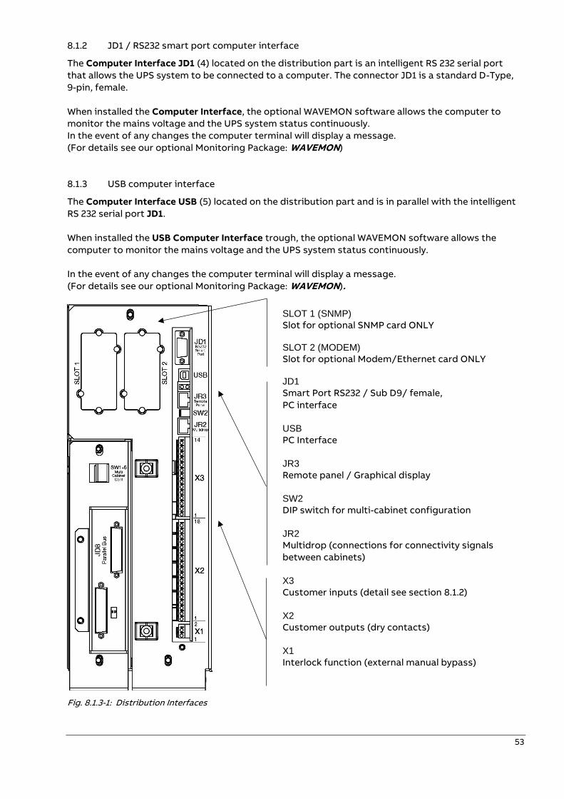
53
8.1.2 JD1 / RS232 smart port computer interface
The Computer Interface JD1 (4) located on the distribution part is an intelligent RS 232 serial port
that allows the UPS system to be connected to a computer. The connector JD1 is a standard D-Type,
9-pin, female.
When installed the Computer Interface, the optional WAVEMON software allows the computer to
monitor the mains voltage and the UPS system status continuously.
In the event of any changes the computer terminal will display a message.
(For details see our optional Monitoring Package: WAVEMON)
8.1.3 USB computer interface
The Computer Interface USB (5) located on the distribution part and is in parallel with the intelligent
RS 232 serial port JD1.
When installed the USB Computer Interface trough, the optional WAVEMON software allows the
computer to monitor the mains voltage and the UPS system status continuously.
In the event of any changes the computer terminal will display a message.
(For details see our optional Monitoring Package: WAVEMON).
Fig. 8.1.3-1: Distribution Interfaces
SLOT 1 (SNMP) Slot for optional SNMP card ONLY SLOT 2 (MODEM) Slot for optional Modem/Ethernet card ONLY JD1
Smart Port RS232 / Sub D9/ female,
PC interface
USB PC Interface
JR3 Remote panel / Graphical display
SW2 DIP switch for multi-cabinet configuration
JR2 Multidrop (connections for connectivity signals
between cabinets)
X3 Customer inputs (detail see section 8.1.2)
X2 Customer outputs (dry contacts)
X1 Interlock function (external manual bypass)
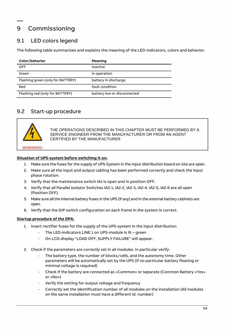
54
—
9 Commissioning
9.1 LED colors legend
The following table summarizes and explains the meaning of the LED-indicators, colors and behavior.
Color/behavior Meaning
OFF inactive
Green in operation
Flashing green (only for BATTERY) battery in discharge
Red fault condition
Flashing red (only for BATTERY) battery low or disconnected
9.2 Start-up procedure
WARNING!
THE OPERATIONS DESCRIBED IN THIS CHAPTER MUST BE PERFORMED BY A SERVICE ENGINEER FROM THE MANUFACTURER OR FROM AN AGENT CERTIFIED BY THE MANUFACTURER
Situation of UPS-system before switching it on:
1. Make sure the fuses for the supply of UPS-System in the input distribution board on site are open.
2. Make sure all the input and output cabling has been performed correctly and check the input
phase rotation.
3. Verify that the maintenance switch IA1 is open and in position OFF.
4. Verify that all Parallel Isolator Switches IA2-1, IA2-2, IA2-3, IA2-4, IA2-5, IA2-6 are all open
(Position OFF).
5. Make sure all the internal battery fuses in the UPS (if any) and in the external battery cabinets are
open.
6. Verify that the DIP switch configuration on each frame in the system is correct.
Startup procedure of the DPA:
1. Insert rectifier fuses for the supply of the UPS-system in the input distribution
- The LED-indicators LINE 1 on UPS-module is lit – green
- On LCD-display “LOAD OFF, SUPPLY FAILURE” will appear.
2. Check if the parameters are correctly set in all modules. In particular verify:
- The battery type, the number of blocks/cells, and the autonomy time. Other
parameters will be automatically set by the UPS (if no particular battery floating or
minimal voltage is required)
- Check if the battery are connected as «Common» or separate (Common Battery «Yes»
or «No»)
- Verify the setting for output voltage and frequency
- Correctly set the identification number of all modules on the installation (All modules
on the same installation must have a different Id. number)
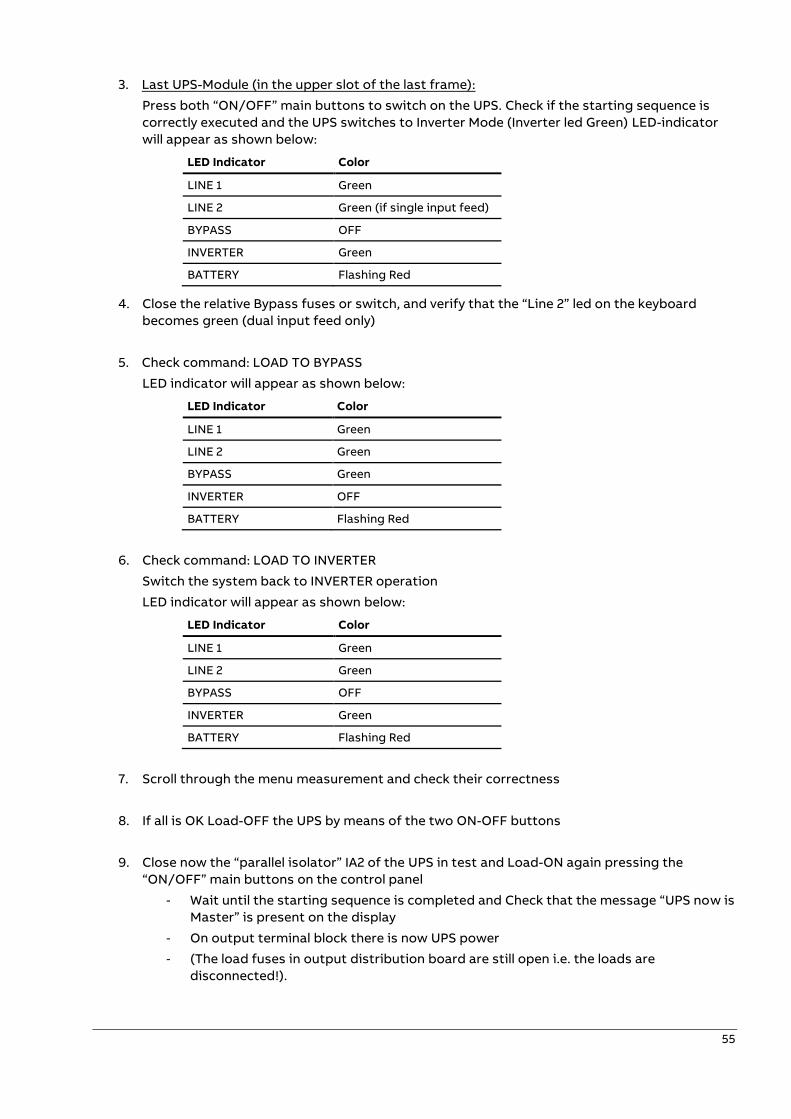
55
3. Last UPS-Module (in the upper slot of the last frame):
Press both “ON/OFF” main buttons to switch on the UPS. Check if the starting sequence is
correctly executed and the UPS switches to Inverter Mode (Inverter led Green) LED-indicator
will appear as shown below:
LED Indicator Color
LINE 1 Green
LINE 2 Green (if single input feed)
BYPASS OFF
INVERTER Green
BATTERY Flashing Red
4. Close the relative Bypass fuses or switch, and verify that the “Line 2” led on the keyboard
becomes green (dual input feed only)
5. Check command: LOAD TO BYPASS
LED indicator will appear as shown below:
LED Indicator Color
LINE 1 Green
LINE 2 Green
BYPASS Green
INVERTER OFF
BATTERY Flashing Red
6. Check command: LOAD TO INVERTER
Switch the system back to INVERTER operation
LED indicator will appear as shown below:
LED Indicator Color
LINE 1 Green
LINE 2 Green
BYPASS OFF
INVERTER Green
BATTERY Flashing Red
7. Scroll through the menu measurement and check their correctness
8. If all is OK Load-OFF the UPS by means of the two ON-OFF buttons
9. Close now the “parallel isolator” IA2 of the UPS in test and Load-ON again pressing the
“ON/OFF” main buttons on the control panel
- Wait until the starting sequence is completed and Check that the message “UPS now is
Master” is present on the display
- On output terminal block there is now UPS power
- (The load fuses in output distribution board are still open i.e. the loads are
disconnected!).
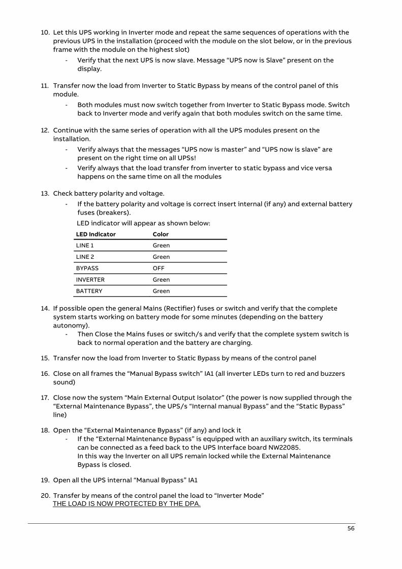
56
10. Let this UPS working in Inverter mode and repeat the same sequences of operations with the
previous UPS in the installation (proceed with the module on the slot below, or in the previous
frame with the module on the highest slot)
- Verify that the next UPS is now slave. Message “UPS now is Slave” present on the
display.
11. Transfer now the load from Inverter to Static Bypass by means of the control panel of this
module.
- Both modules must now switch together from Inverter to Static Bypass mode. Switch
back to Inverter mode and verify again that both modules switch on the same time.
12. Continue with the same series of operation with all the UPS modules present on the
installation.
- Verify always that the messages “UPS now is master” and “UPS now is slave” are
present on the right time on all UPSs!
- Verify always that the load transfer from inverter to static bypass and vice versa
happens on the same time on all the modules
13. Check battery polarity and voltage.
- If the battery polarity and voltage is correct insert internal (if any) and external battery
fuses (breakers).
LED indicator will appear as shown below:
LED Indicator Color
LINE 1 Green
LINE 2 Green
BYPASS OFF
INVERTER Green
BATTERY Green
14. If possible open the general Mains (Rectifier) fuses or switch and verify that the complete
system starts working on battery mode for some minutes (depending on the battery
autonomy).
- Then Close the Mains fuses or switch/s and verify that the complete system switch is
back to normal operation and the battery are charging.
15. Transfer now the load from Inverter to Static Bypass by means of the control panel
16. Close on all frames the “Manual Bypass switch” IA1 (all inverter LEDs turn to red and buzzers
sound)
17. Close now the system “Main External Output Isolator” (the power is now supplied through the
“External Maintenance Bypass”, the UPS/s “Internal manual Bypass” and the “Static Bypass”
line)
18. Open the “External Maintenance Bypass” (if any) and lock it
- If the “External Maintenance Bypass” is equipped with an auxiliary switch, its terminals
can be connected as a feed back to the UPS Interface board NW22085.
In this way the Inverter on all UPS remain locked while the External Maintenance
Bypass is closed.
19. Open all the UPS internal “Manual Bypass” IA1
20. Transfer by means of the control panel the load to “Inverter Mode” THE LOAD IS NOW PROTECTED BY THE DPA.
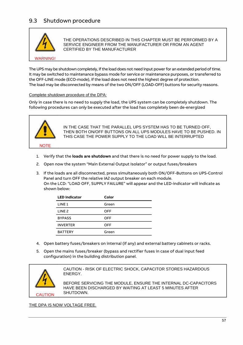
57
9.3 Shutdown procedure
WARNING!
THE OPERATIONS DESCRIBED IN THIS CHAPTER MUST BE PERFORMED BY A SERVICE ENGINEER FROM THE MANUFACTURER OR FROM AN AGENT CERTIFIED BY THE MANUFACTURER
The UPS may be shutdown completely, if the load does not need input power for an extended period of time.
It may be switched to maintenance bypass mode for service or maintenance purposes, or transferred to
the OFF-LINE mode (ECO-mode), if the load does not need the highest degree of protection.
The load may be disconnected by means of the two ON/OFF (LOAD-OFF) buttons for security reasons.
Complete shutdown procedure of the DPA:
Only in case there is no need to supply the load, the UPS system can be completely shutdown. The
following procedures can only be executed after the load has completely been de-energized
NOTE
IN THE CASE THAT THE PARALLEL UPS SYSTEM HAS TO BE TURNED OFF, THEN BOTH ON/OFF BUTTONS ON ALL UPS MODULES HAVE TO BE PUSHED. IN THIS CASE THE POWER SUPPLY TO THE LOAD WILL BE INTERRUPTED
1. Verify that the loads are shutdown and that there is no need for power supply to the load.
2. Open now the system “Main External Output Isolator” or output fuses/breakers
3. If the loads are all disconnected, press simultaneously both ON/OFF-Buttons on UPS-Control
Panel and turn OFF the relative IA2 output breaker on each module.
On the LCD: “LOAD OFF, SUPPLY FAILURE” will appear and the LED-indicator will indicate as
shown below:
LED Indicator Color
LINE 1 Green
LINE 2 OFF
BYPASS OFF
INVERTER OFF
BATTERY Green
4. Open battery fuses/breakers on internal (if any) and external battery cabinets or racks.
5. Open the mains fuses/breaker (bypass and rectifier fuses in case of dual input feed
configuration) in the building distribution panel.
CAUTION
CAUTION - RISK OF ELECTRIC SHOCK, CAPACITOR STORES HAZARDOUS ENERGY. BEFORE SERVICING THE MODULE, ENSURE THE INTERNAL DC-CAPACITORS HAVE BEEN DISCHARGED BY WAITING AT LEAST 5 MINUTES AFTER SHUTDOWN.
THE DPA IS NOW VOLTAGE FREE.
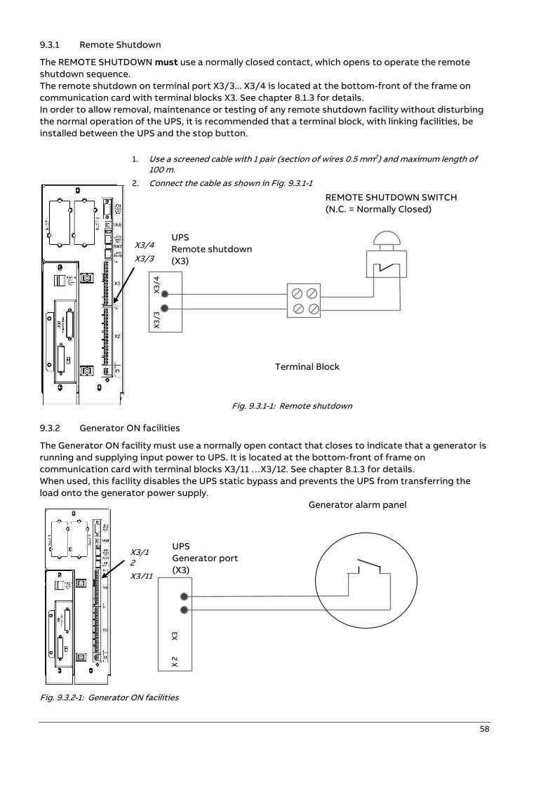
58
9.3.1 Remote Shutdown
The REMOTE SHUTDOWN must use a normally closed contact, which opens to operate the remote
shutdown sequence.
The remote shutdown on terminal port X3/3... X3/4 is located at the bottom-front of the frame on
communication card with terminal blocks X3. See chapter 8.1.3 for details.
In order to allow removal, maintenance or testing of any remote shutdown facility without disturbing
the normal operation of the UPS, it is recommended that a terminal block, with linking facilities, be
installed between the UPS and the stop button.
1. Use a screened cable with 1 pair (section of wires 0.5 mm2) and maximum length of 100 m.
2. Connect the cable as shown in Fig. 9.3.1-1
REMOTE SHUTDOWN SWITCH
(N.C. = Normally Closed)
UPS
Remote shutdown
(X3)
Terminal Block
Fig. 9.3.1-1: Remote shutdown
9.3.2 Generator ON facilities
The Generator ON facility must use a normally open contact that closes to indicate that a generator is
running and supplying input power to UPS. It is located at the bottom-front of frame on
communication card with terminal blocks X3/11 …X3/12. See chapter 8.1.3 for details.
When used, this facility disables the UPS static bypass and prevents the UPS from transferring the
load onto the generator power supply.
Generator alarm panel
UPS
Generator port
(X3)
Fig. 9.3.2-1: Generator ON facilities
X3
/3
X
3/
4
X3/4
X3/3
X3/12
X3/11
X 2
X
3
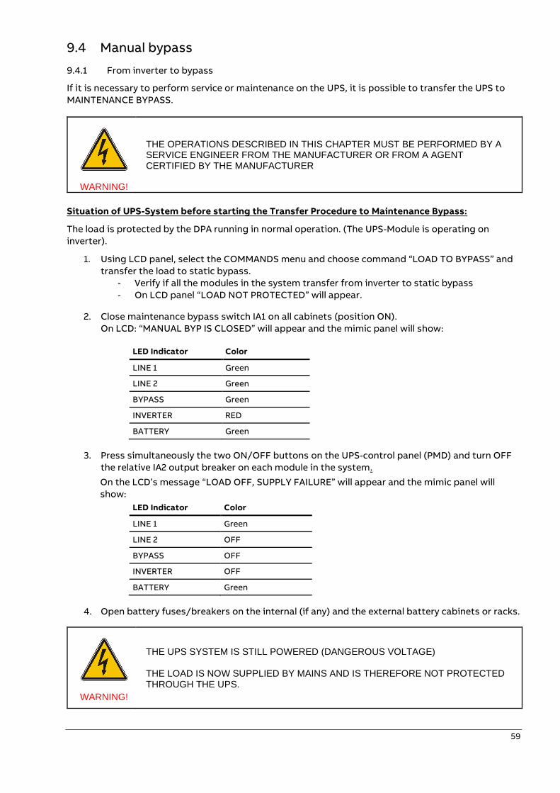
59
9.4 Manual bypass
9.4.1 From inverter to bypass
If it is necessary to perform service or maintenance on the UPS, it is possible to transfer the UPS to
MAINTENANCE BYPASS.
WARNING!
THE OPERATIONS DESCRIBED IN THIS CHAPTER MUST BE PERFORMED BY A SERVICE ENGINEER FROM THE MANUFACTURER OR FROM A AGENT CERTIFIED BY THE MANUFACTURER
Situation of UPS-System before starting the Transfer Procedure to Maintenance Bypass:
The load is protected by the DPA running in normal operation. (The UPS-Module is operating on
inverter).
1. Using LCD panel, select the COMMANDS menu and choose command “LOAD TO BYPASS” and
transfer the load to static bypass.
- Verify if all the modules in the system transfer from inverter to static bypass
- On LCD panel “LOAD NOT PROTECTED” will appear.
2. Close maintenance bypass switch IA1 on all cabinets (position ON).
On LCD: “MANUAL BYP IS CLOSED” will appear and the mimic panel will show:
LED Indicator Color
LINE 1 Green
LINE 2 Green
BYPASS Green
INVERTER RED
BATTERY Green
3. Press simultaneously the two ON/OFF buttons on the UPS-control panel (PMD) and turn OFF
the relative IA2 output breaker on each module in the system.
On the LCD’s message “LOAD OFF, SUPPLY FAILURE” will appear and the mimic panel will
show:
LED Indicator Color
LINE 1 Green
LINE 2 OFF
BYPASS OFF
INVERTER OFF
BATTERY Green
4. Open battery fuses/breakers on the internal (if any) and the external battery cabinets or racks.
WARNING!
THE UPS SYSTEM IS STILL POWERED (DANGEROUS VOLTAGE) THE LOAD IS NOW SUPPLIED BY MAINS AND IS THEREFORE NOT PROTECTED THROUGH THE UPS.
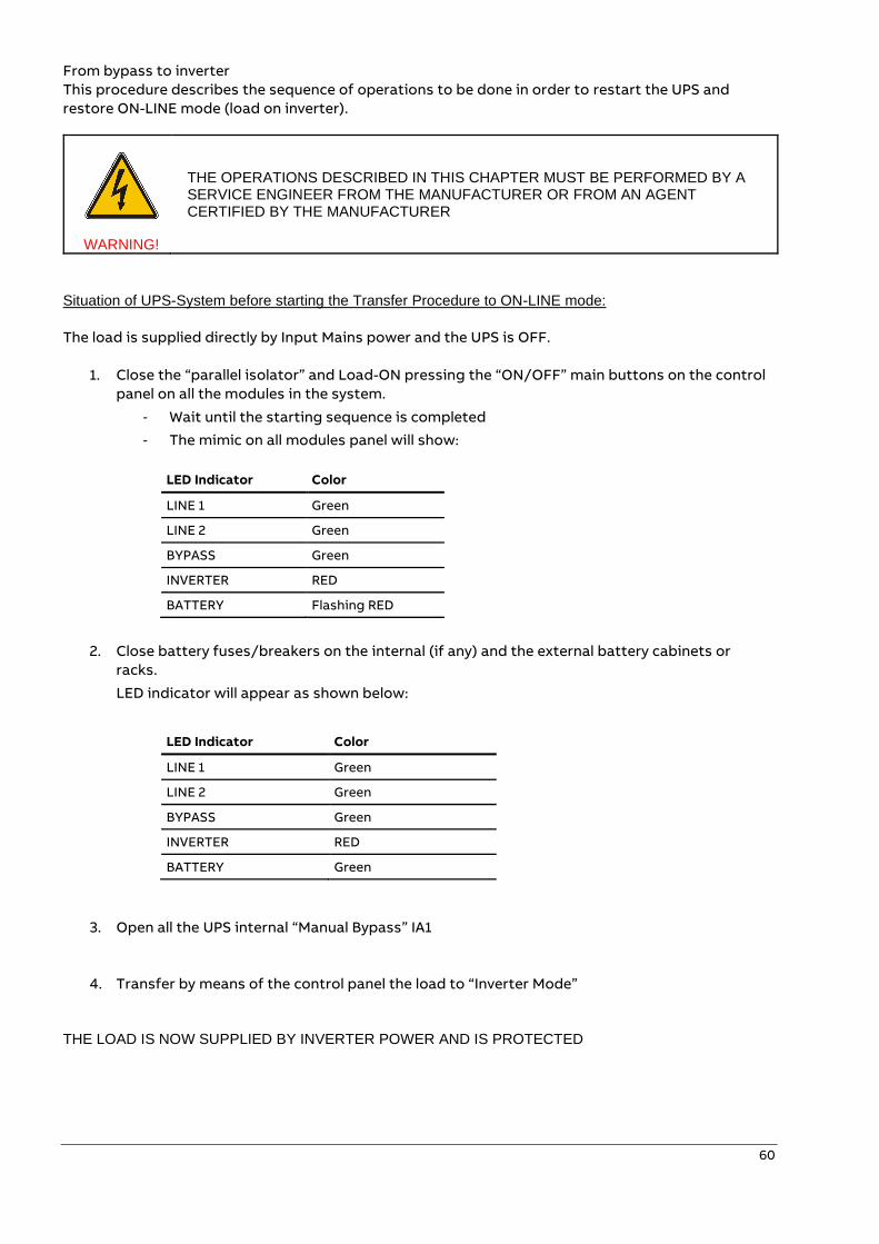
60
From bypass to inverter
This procedure describes the sequence of operations to be done in order to restart the UPS and
restore ON-LINE mode (load on inverter).
WARNING!
THE OPERATIONS DESCRIBED IN THIS CHAPTER MUST BE PERFORMED BY A SERVICE ENGINEER FROM THE MANUFACTURER OR FROM AN AGENT CERTIFIED BY THE MANUFACTURER
Situation of UPS-System before starting the Transfer Procedure to ON-LINE mode:
The load is supplied directly by Input Mains power and the UPS is OFF.
1. Close the “parallel isolator” and Load-ON pressing the “ON/OFF” main buttons on the control
panel on all the modules in the system.
- Wait until the starting sequence is completed
- The mimic on all modules panel will show:
LED Indicator Color
LINE 1 Green
LINE 2 Green
BYPASS Green
INVERTER RED
BATTERY Flashing RED
2. Close battery fuses/breakers on the internal (if any) and the external battery cabinets or
racks.
LED indicator will appear as shown below:
LED Indicator Color
LINE 1 Green
LINE 2 Green
BYPASS Green
INVERTER RED
BATTERY Green
3. Open all the UPS internal “Manual Bypass” IA1
4. Transfer by means of the control panel the load to “Inverter Mode”
THE LOAD IS NOW SUPPLIED BY INVERTER POWER AND IS PROTECTED
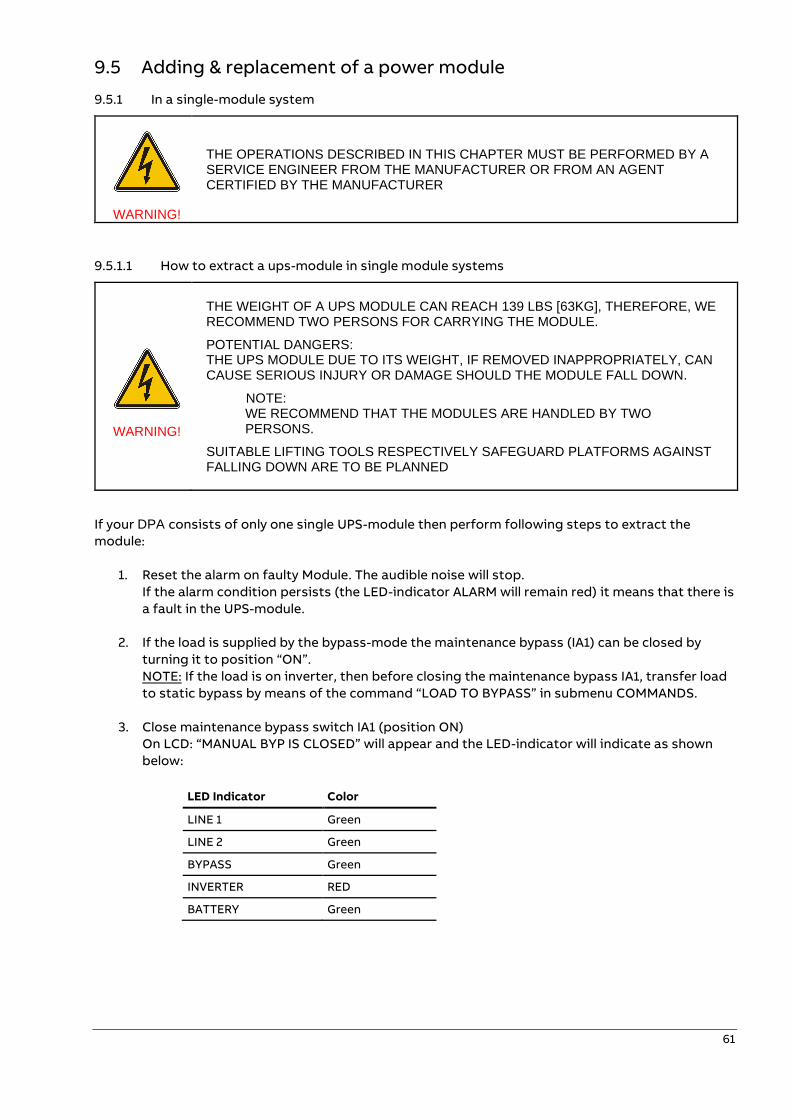
61
9.5 Adding & replacement of a power module
9.5.1 In a single-module system
WARNING!
THE OPERATIONS DESCRIBED IN THIS CHAPTER MUST BE PERFORMED BY A SERVICE ENGINEER FROM THE MANUFACTURER OR FROM AN AGENT CERTIFIED BY THE MANUFACTURER
9.5.1.1 How to extract a ups-module in single module systems
WARNING!
THE WEIGHT OF A UPS MODULE CAN REACH 139 LBS [63KG], THEREFORE, WE RECOMMEND TWO PERSONS FOR CARRYING THE MODULE.
POTENTIAL DANGERS: THE UPS MODULE DUE TO ITS WEIGHT, IF REMOVED INAPPROPRIATELY, CAN CAUSE SERIOUS INJURY OR DAMAGE SHOULD THE MODULE FALL DOWN.
NOTE: WE RECOMMEND THAT THE MODULES ARE HANDLED BY TWO
PERSONS.
SUITABLE LIFTING TOOLS RESPECTIVELY SAFEGUARD PLATFORMS AGAINST FALLING DOWN ARE TO BE PLANNED
If your DPA consists of only one single UPS-module then perform following steps to extract the
module:
1. Reset the alarm on faulty Module. The audible noise will stop.
If the alarm condition persists (the LED-indicator ALARM will remain red) it means that there is
a fault in the UPS-module.
2. If the load is supplied by the bypass-mode the maintenance bypass (IA1) can be closed by
turning it to position “ON”.
NOTE: If the load is on inverter, then before closing the maintenance bypass IA1, transfer load
to static bypass by means of the command “LOAD TO BYPASS” in submenu COMMANDS.
3. Close maintenance bypass switch IA1 (position ON)
On LCD: “MANUAL BYP IS CLOSED” will appear and the LED-indicator will indicate as shown
below:
LED Indicator Color
LINE 1 Green
LINE 2 Green
BYPASS Green
INVERTER RED
BATTERY Green
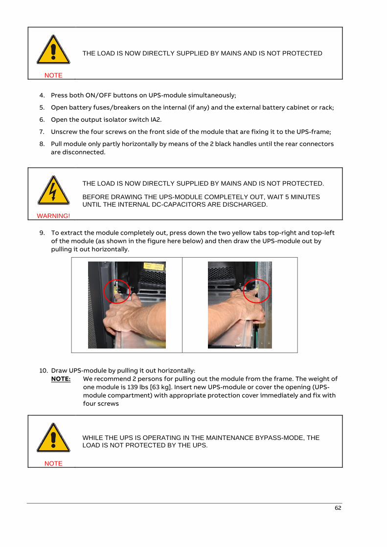
62
NOTE
THE LOAD IS NOW DIRECTLY SUPPLIED BY MAINS AND IS NOT PROTECTED
4. Press both ON/OFF buttons on UPS-module simultaneously;
5. Open battery fuses/breakers on the internal (if any) and the external battery cabinet or rack;
6. Open the output isolator switch IA2.
7. Unscrew the four screws on the front side of the module that are fixing it to the UPS-frame;
8. Pull module only partly horizontally by means of the 2 black handles until the rear connectors
are disconnected.
WARNING!
THE LOAD IS NOW DIRECTLY SUPPLIED BY MAINS AND IS NOT PROTECTED.
BEFORE DRAWING THE UPS-MODULE COMPLETELY OUT, WAIT 5 MINUTES UNTIL THE INTERNAL DC-CAPACITORS ARE DISCHARGED.
9. To extract the module completely out, press down the two yellow tabs top-right and top-left
of the module (as shown in the figure here below) and then draw the UPS-module out by
pulling it out horizontally.
10. Draw UPS-module by pulling it out horizontally:
NOTE: We recommend 2 persons for pulling out the module from the frame. The weight of
one module is 139 lbs [63 kg]. Insert new UPS-module or cover the opening (UPS-
module compartment) with appropriate protection cover immediately and fix with
four screws
NOTE
WHILE THE UPS IS OPERATING IN THE MAINTENANCE BYPASS-MODE, THE LOAD IS NOT PROTECTED BY THE UPS.
63
9.5.1.2 How to insert the ups-module in single-module-systems
If your DPA consists of only one single UPS-module then perform following steps to fit back the new
module:
1. Remove UPS-Module compartment protection cover by unscrewing four screws on the front.
2. Make sure that the parallel switch “IA2” of the slot where the module need to be inserted is
OFF
3. Make sure that the “battery breakers” of the slot where the module need to be inserted are
OFF
4. Slide two thirds of UPS-Module into dedicated UPS-compartment (make sure not to plug the
UPS-module into the rear connector).
Push UPS-module to its final position and push firmly to assure good contact on the rear
plugs.
NOTE: We recommend 2 persons for insert the module into the frame. The weight of one
module is 139 lbs [63 kg].
5. Tighten the four screws on the front of module with a tighten torque of 6 Nm.
6. Check if the LED LINE1 and LINE2 lit green. If yes, mains voltage is OK;
7. Load-on the module by pushing the two ON/OFF keys at the same time
8. Check if the starting sequence is correctly executed, with the module running in inverter mode
at the end
9. Give the command “LOAD TO BYPASS” to switch the module in static bypass mode
- Check if the command is correctly executed, with the module running in static bypass
mode at the end
10. Give the command “LOAD TO INVERTER” to switch the module in inverter mode
- Check if the command is correctly executed, with the module running in inverter mode
at the end
11. Close internal and external battery fuses/breaker (if available);
- Wait until the BATTERY LED on the module’s control panel is green, this means that the
batteries are connected and are ok
12. Load-off the module by pushing the two ON/OFF keys at the same time
13. Connect the module to the parallel system by turning ON the parallel switch “IA2”
14. Press simultaneously both “ON/OFF” Buttons to start-up UPS.
LCD panel must display: LED-indicator will appear as shown below:
LED Indicator Color
LINE 1 Green
LINE 2 Green
BYPASS Green
INVERTER RED
BATTERY Green
15. Open maintenance bypass (IA1) by turning it to position “OFF”. The load is now supplied by
the static bypass.
16. Transfer load to inverter-mode by means of COMMAND “LOAD TO INVERTER”. On LCD: “LOAD
PROTECTED” will appear. THE LOAD IS NOW PROTECTED BY THE DPA.
64
9.5.2 In a redundant multi-module system
WARNING!
THE WEIGHT OF A UPS MODULE REACH 139 LBS [63KG], THEREFORE IT IS RECOMMENDED TO BE LIFTED BY TWO PERSONS. THE MODULE SHALL NEVER BE CARRIED BY ONE PERSON ONLY.
MAKE SURE THE INTERNAL DC-CAPACITORS HAVE BEEN DISCHARGED WAITING AT LEAST 5 MINUTES.
9.5.2.1 How to extract a module in redundant multi-module system
If in a redundant parallel system, the UPS-module is faulty, the load will continue to be protected by
the operating modules on-line-mode (inverter-mode) and the faulty module may be replaced without
having to transfer the load to bypass.
To extract the faulty module from the UPS-Frame in a Redundant Multi- Module Configuration
proceed as follows:
1. Identify the faulty Module with the Alarm condition and RESET the Alarm. The audible noise
will stop. If the Alarm conditions persists (the LED-Indicator ALARM is red) there is a fault in
the UPS-Module.
2. Verify that load is supplied by inverter of the other modules running by checking the LCD
indication LOAD PROTECTED. Verify load measures on the operating modules.
3. Turn the faulty module OFF by pressing simultaneously both “ON/OFF” buttons.
On the LCD: “LOAD OFF, SUPPLY FAILURE” should appear and the LED-indicator will indicate
as shown below:
LED Indicator Color
LINE 1 Green
LINE 2 OFF
BYPASS OFF
INVERTER OFF
BATTERY Green
4. Turn OFF the relative output isolator IA2
5. Remove the four fixing screws and pull the module only partially out, horizontally by means of
the 2 black handles until the rear connectors are disconnected.
WARNING!
BEFORE DRAWING THE UPS-MODULE COMPLETELY OUT, WAIT 5 MINUTES UNTIL THE INTERNAL DC-CAPACITORS ARE DISCHARGED
NOTE
WE RECOMMEND 2 PERSONS FOR PULLING OUT THE MODULE FROM THE UPS-FRAME. THE WEIGHT OF A MODULE REACH 139 LBS [63KG].
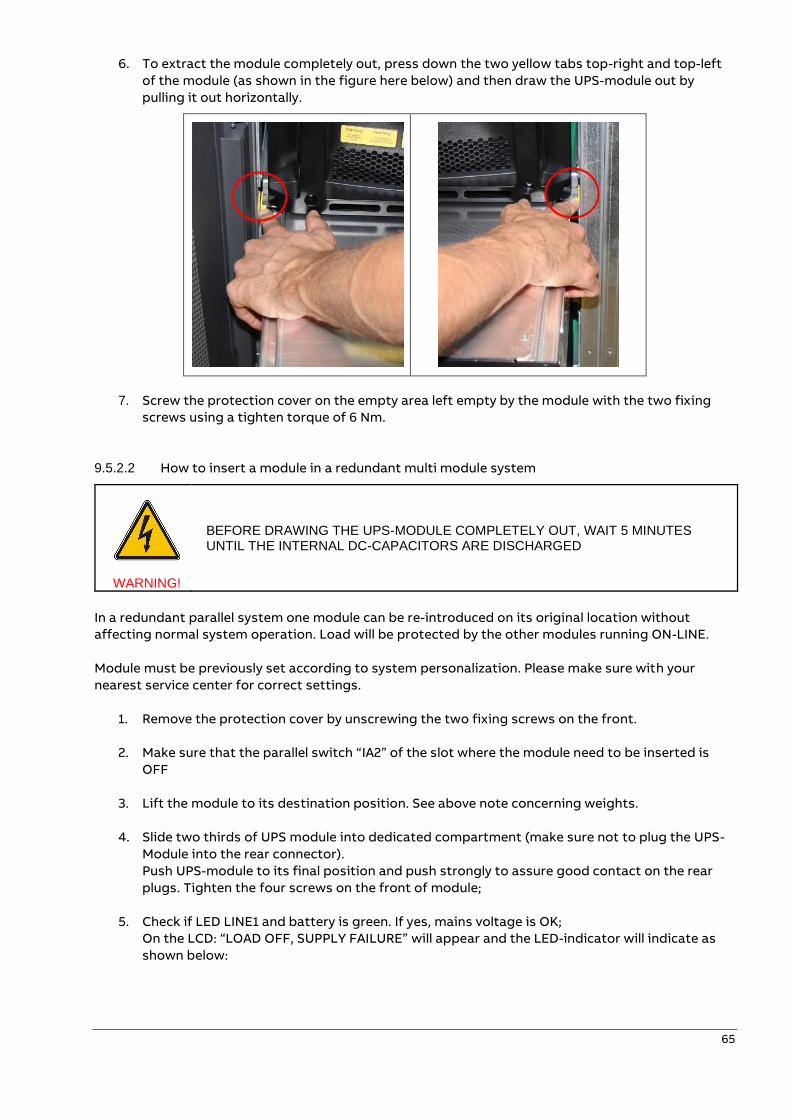
65
6. To extract the module completely out, press down the two yellow tabs top-right and top-left
of the module (as shown in the figure here below) and then draw the UPS-module out by
pulling it out horizontally.
7. Screw the protection cover on the empty area left empty by the module with the two fixing
screws using a tighten torque of 6 Nm.
9.5.2.2 How to insert a module in a redundant multi module system
WARNING!
BEFORE DRAWING THE UPS-MODULE COMPLETELY OUT, WAIT 5 MINUTES UNTIL THE INTERNAL DC-CAPACITORS ARE DISCHARGED
In a redundant parallel system one module can be re-introduced on its original location without
affecting normal system operation. Load will be protected by the other modules running ON-LINE.
Module must be previously set according to system personalization. Please make sure with your
nearest service center for correct settings.
1. Remove the protection cover by unscrewing the two fixing screws on the front.
2. Make sure that the parallel switch “IA2” of the slot where the module need to be inserted is
OFF
3. Lift the module to its destination position. See above note concerning weights.
4. Slide two thirds of UPS module into dedicated compartment (make sure not to plug the UPS-
Module into the rear connector).
Push UPS-module to its final position and push strongly to assure good contact on the rear
plugs. Tighten the four screws on the front of module;
5. Check if LED LINE1 and battery is green. If yes, mains voltage is OK;
On the LCD: “LOAD OFF, SUPPLY FAILURE” will appear and the LED-indicator will indicate as
shown below:
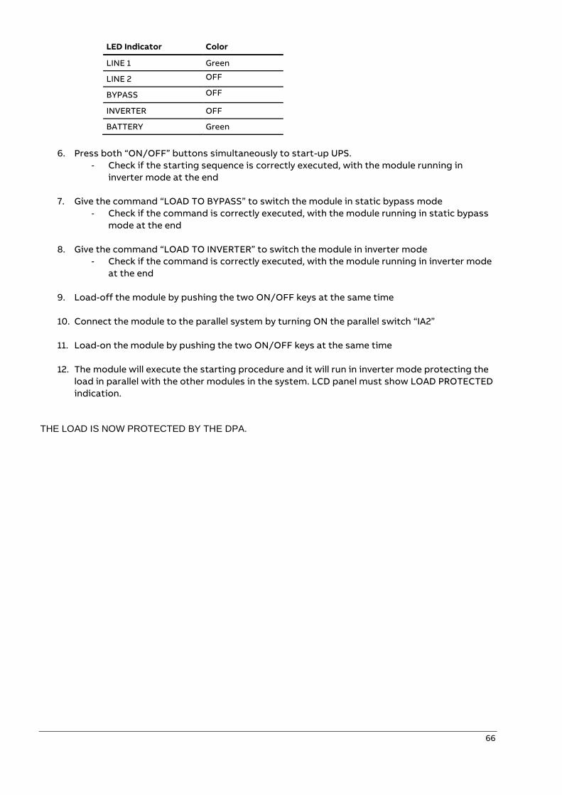
66
LED Indicator Color
LINE 1 Green
LINE 2 OFF
BYPASS OFF
INVERTER OFF
BATTERY Green
6. Press both “ON/OFF” buttons simultaneously to start-up UPS.
- Check if the starting sequence is correctly executed, with the module running in
inverter mode at the end
7. Give the command “LOAD TO BYPASS” to switch the module in static bypass mode
- Check if the command is correctly executed, with the module running in static bypass
mode at the end
8. Give the command “LOAD TO INVERTER” to switch the module in inverter mode
- Check if the command is correctly executed, with the module running in inverter mode
at the end
9. Load-off the module by pushing the two ON/OFF keys at the same time
10. Connect the module to the parallel system by turning ON the parallel switch “IA2”
11. Load-on the module by pushing the two ON/OFF keys at the same time
12. The module will execute the starting procedure and it will run in inverter mode protecting the
load in parallel with the other modules in the system. LCD panel must show LOAD PROTECTED
indication.
THE LOAD IS NOW PROTECTED BY THE DPA.
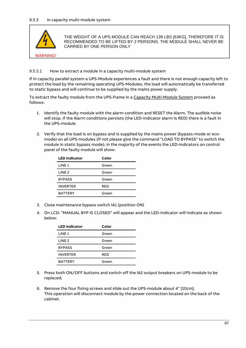
67
9.5.3 In capacity multi-module system
WARNING!
THE WEIGHT OF A UPS MODULE CAN REACH 139 LBS [63KG], THEREFORE IT IS RECOMMENDED TO BE LIFTED BY 2 PERSONS. THE MODULE SHALL NEVER BE CARRIED BY ONE PERSON ONLY
9.5.3.1 How to extract a module in a capacity multi-module system
If in capacity parallel system a UPS-Module experiences a fault and there is not enough capacity left to
protect the load by the remaining operating UPS-Modules, the load will automatically be transferred
to static bypass and will continue to be supplied by the mains power supply.
To extract the faulty module from the UPS-frame in a Capacity Multi-Module System proceed as
follows:
1. Identify the faulty module with the alarm condition and RESET the Alarm. The audible noise
will stop. If the Alarm conditions persists (the LED-indicator alarm is RED) there is a fault in
the UPS-module.
2. Verify that the load is on bypass and is supplied by the mains power (bypass-mode or eco-
mode) on all UPS-modules (if not please give the command “LOAD TO BYPASS” to switch the
module in static bypass mode); in the majority of the events the LED-indicators on control
panel of the faulty module will show:
LED Indicator Color
LINE 1 Green
LINE 2 Green
BYPASS Green
INVERTER RED
BATTERY Green
3. Close maintenance bypass switch IA1 (position ON)
4. On LCD: “MANUAL BYP IS CLOSED” will appear and the LED-indicator will indicate as shown
below:
LED Indicator Color
LINE 1 Green
LINE 2 Green
BYPASS Green
INVERTER RED
BATTERY Green
5. Press both ON/OFF buttons and switch off the IA2 output breakers on UPS-module to be
replaced;
6. Remove the four fixing screws and slide out the UPS-module about 4” [10cm].
This operation will disconnect module by the power connection located on the back of the
cabinet.
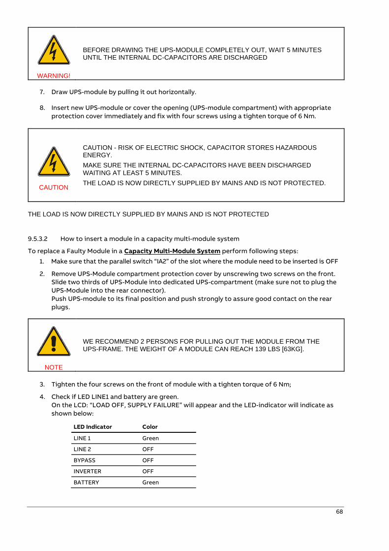
68
WARNING!
BEFORE DRAWING THE UPS-MODULE COMPLETELY OUT, WAIT 5 MINUTES UNTIL THE INTERNAL DC-CAPACITORS ARE DISCHARGED
7. Draw UPS-module by pulling it out horizontally.
8. Insert new UPS-module or cover the opening (UPS-module compartment) with appropriate
protection cover immediately and fix with four screws using a tighten torque of 6 Nm.
CAUTION
CAUTION - RISK OF ELECTRIC SHOCK, CAPACITOR STORES HAZARDOUS ENERGY.
MAKE SURE THE INTERNAL DC-CAPACITORS HAVE BEEN DISCHARGED WAITING AT LEAST 5 MINUTES.
THE LOAD IS NOW DIRECTLY SUPPLIED BY MAINS AND IS NOT PROTECTED.
THE LOAD IS NOW DIRECTLY SUPPLIED BY MAINS AND IS NOT PROTECTED
9.5.3.2 How to insert a module in a capacity multi-module system
To replace a Faulty Module in a Capacity Multi-Module System perform following steps:
1. Make sure that the parallel switch “IA2” of the slot where the module need to be inserted is OFF
2. Remove UPS-Module compartment protection cover by unscrewing two screws on the front.
Slide two thirds of UPS-Module into dedicated UPS-compartment (make sure not to plug the
UPS-Module into the rear connector).
Push UPS-module to its final position and push strongly to assure good contact on the rear
plugs.
NOTE
WE RECOMMEND 2 PERSONS FOR PULLING OUT THE MODULE FROM THE UPS-FRAME. THE WEIGHT OF A MODULE CAN REACH 139 LBS [63KG].
3. Tighten the four screws on the front of module with a tighten torque of 6 Nm;
4. Check if LED LINE1 and battery are green.
On the LCD: “LOAD OFF, SUPPLY FAILURE” will appear and the LED-indicator will indicate as
shown below:
LED Indicator Color
LINE 1 Green
LINE 2 OFF
BYPASS OFF
INVERTER OFF
BATTERY Green
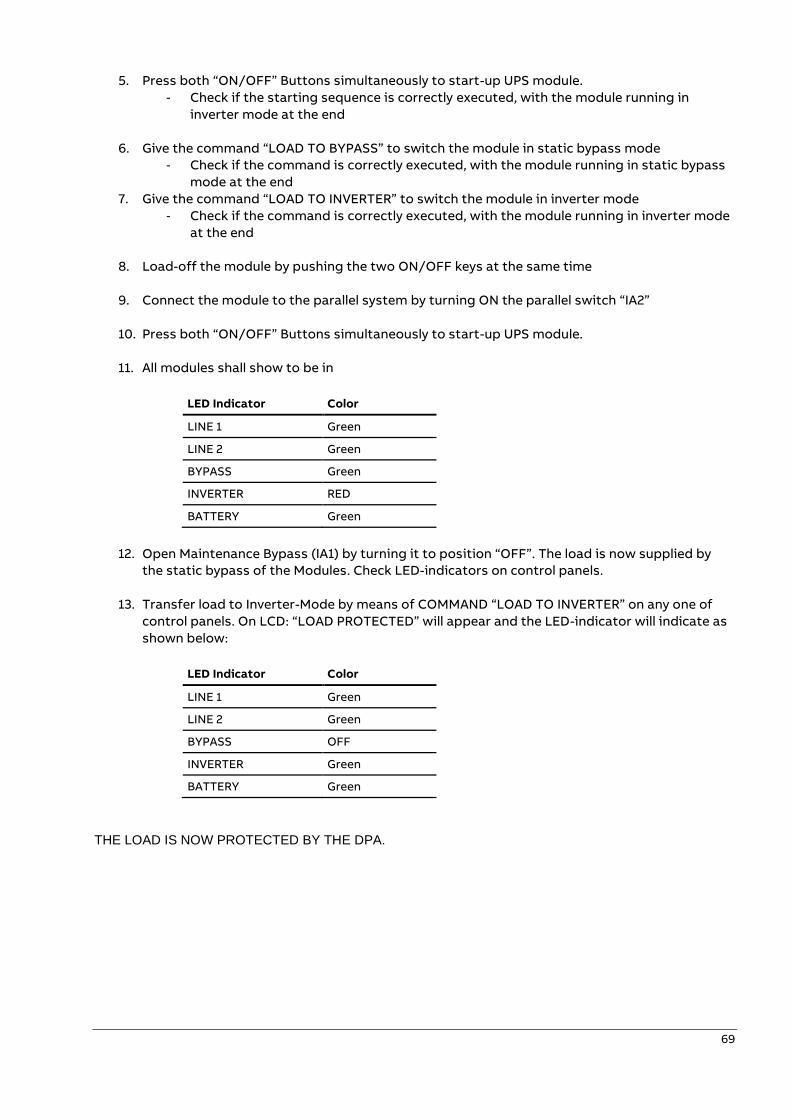
69
5. Press both “ON/OFF” Buttons simultaneously to start-up UPS module.
- Check if the starting sequence is correctly executed, with the module running in
inverter mode at the end
6. Give the command “LOAD TO BYPASS” to switch the module in static bypass mode
- Check if the command is correctly executed, with the module running in static bypass
mode at the end
7. Give the command “LOAD TO INVERTER” to switch the module in inverter mode
- Check if the command is correctly executed, with the module running in inverter mode
at the end
8. Load-off the module by pushing the two ON/OFF keys at the same time
9. Connect the module to the parallel system by turning ON the parallel switch “IA2”
10. Press both “ON/OFF” Buttons simultaneously to start-up UPS module.
11. All modules shall show to be in
LED Indicator Color
LINE 1 Green
LINE 2 Green
BYPASS Green
INVERTER RED
BATTERY Green
12. Open Maintenance Bypass (IA1) by turning it to position “OFF”. The load is now supplied by
the static bypass of the Modules. Check LED-indicators on control panels.
13. Transfer load to Inverter-Mode by means of COMMAND “LOAD TO INVERTER” on any one of
control panels. On LCD: “LOAD PROTECTED” will appear and the LED-indicator will indicate as
shown below:
LED Indicator Color
LINE 1 Green
LINE 2 Green
BYPASS OFF
INVERTER Green
BATTERY Green
THE LOAD IS NOW PROTECTED BY THE DPA.
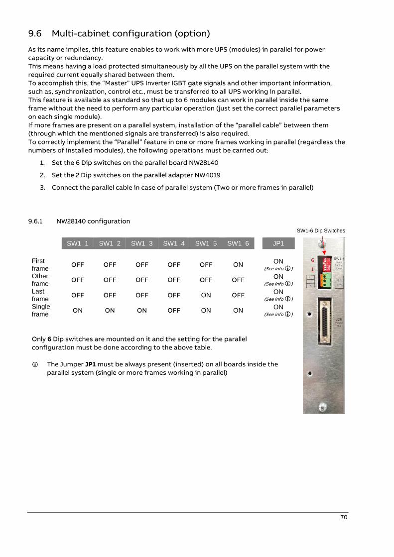
70
9.6 Multi-cabinet configuration (option)
As its name implies, this feature enables to work with more UPS (modules) in parallel for power
capacity or redundancy.
This means having a load protected simultaneously by all the UPS on the parallel system with the
required current equally shared between them.
To accomplish this, the “Master” UPS Inverter IGBT gate signals and other important information,
such as, synchronization, control etc., must be transferred to all UPS working in parallel.
This feature is available as standard so that up to 6 modules can work in parallel inside the same
frame without the need to perform any particular operation (just set the correct parallel parameters
on each single module).
If more frames are present on a parallel system, installation of the “parallel cable” between them
(through which the mentioned signals are transferred) is also required.
To correctly implement the “Parallel” feature in one or more frames working in parallel (regardless the
numbers of installed modules), the following operations must be carried out:
1. Set the 6 Dip switches on the parallel board NW28140
2. Set the 2 Dip switches on the parallel adapter NW4019
3. Connect the parallel cable in case of parallel system (Two or more frames in parallel)
9.6.1 NW28140 configuration
SW1 1 SW1 2 SW1 3 SW1 4 SW1 5 SW1 6 JP1
First frame
OFF OFF OFF OFF OFF ON ON
(See info )
Other frame
OFF OFF OFF OFF OFF OFF ON (See info )
Last frame
OFF OFF OFF OFF ON OFF ON
(See info ) Single frame
ON ON ON OFF ON ON ON
(See info )
Only 6 Dip switches are mounted on it and the setting for the parallel
configuration must be done according to the above table.
The Jumper JP1 must be always present (inserted) on all boards inside the
parallel system (single or more frames working in parallel)
SW1-6 Dip Switches
6
1
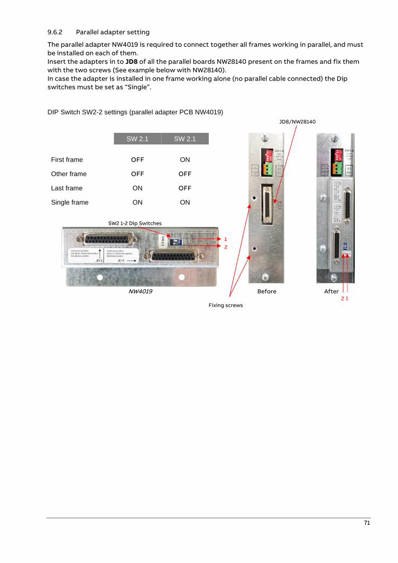
71
9.6.2 Parallel adapter setting
The parallel adapter NW4019 is required to connect together all frames working in parallel, and must
be installed on each of them.
Insert the adapters in to JD8 of all the parallel boards NW28140 present on the frames and fix them
with the two screws (See example below with NW28140).
In case the adapter is installed in one frame working alone (no parallel cable connected) the Dip
switches must be set as “Single”.
DIP Switch SW2-2 settings (parallel adapter PCB NW4019)
SW 2.1 SW 2.1
Before
After
First frame OFF ON
Other frame OFF OFF
Last frame ON OFF
Single frame ON ON
NW4019
JD8/NW28140
SW2 1-2 Dip Switches
1
2
Fixing screws
1 2
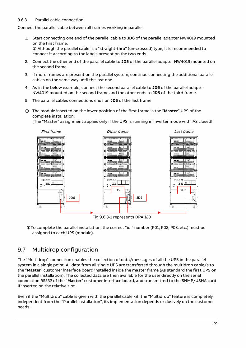
72
9.6.3 Parallel cable connection
Connect the parallel cable between all frames working in parallel.
1. Start connecting one end of the parallel cable to JD6 of the parallel adapter NW4019 mounted
on the first frame.
Although the parallel cable is a “straight-thru” (un-crossed) type, it is recommended to
connect it according to the labels present on the two ends.
2. Connect the other end of the parallel cable to JD5 of the parallel adapter NW4019 mounted on
the second frame.
3. If more frames are present on the parallel system, continue connecting the additional parallel
cables on the same way until the last one.
4. As in the below example, connect the second parallel cable to JD6 of the parallel adapter
NW4019 mounted on the second frame and the other ends to JD5 of the third frame.
5. The parallel cables connections ends on JD5 of the last frame
The module inserted on the lower position of the first frame is the “Master” UPS of the
complete installation.
(The “Master” assignment applies only if the UPS is running in Inverter mode with IA2 closed!
First frame
Other frame
Last frame
Fig 9.6.3-1 represents DPA 120
To complete the parallel installation, the correct “id.” number (P01, P02, P03, etc.) must be
assigned to each UPS (module).
9.7 Multidrop configuration
The “Multidrop” connection enables the collection of data/messages of all the UPS in the parallel
system in a single point. All data from all single UPS are transferred through the multidrop cable/s to
the “Master” customer interface board installed inside the master frame (As standard the first UPS on
the parallel installation). The collected data are then available for the user directly on the serial
connection RS232 of the “Master” customer interface board, and transmitted to the SNMP/USHA card
if inserted on the relative slot.
Even if the “Multidrop” cable is given with the parallel cable kit, the “Multidrop” feature is completely
independent from the “Parallel installation”, its implementation depends exclusively on the customer
needs.
JD5
JD6
JD5
JD6
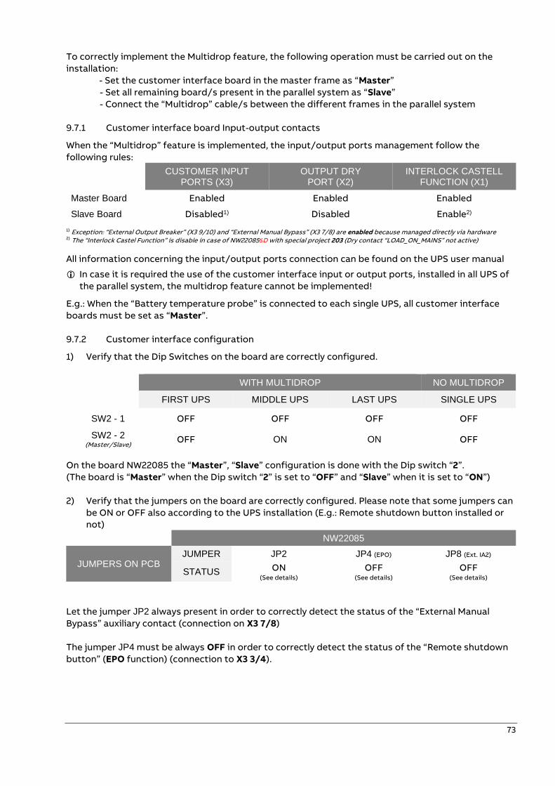
73
To correctly implement the Multidrop feature, the following operation must be carried out on the
installation:
- Set the customer interface board in the master frame as “Master”
- Set all remaining board/s present in the parallel system as “Slave”
- Connect the “Multidrop” cable/s between the different frames in the parallel system
9.7.1 Customer interface board Input-output contacts
When the “Multidrop” feature is implemented, the input/output ports management follow the
following rules: CUSTOMER INPUT
PORTS (X3) OUTPUT DRY
PORT (X2) INTERLOCK CASTELL
FUNCTION (X1)
Master Board Enabled Enabled Enabled
Slave Board Disabled1) Disabled Enable2) 1) Exception: “External Output Breaker” (X3 9/10) and “External Manual Bypass” (X3 7/8) are enabled because managed directly via hardware 2) The “Interlock Castel Function” is disable in case of NW22085≤D with special project 203 (Dry contact “LOAD_ON_MAINS” not active)
All information concerning the input/output ports connection can be found on the UPS user manual
In case it is required the use of the customer interface input or output ports, installed in all UPS of
the parallel system, the multidrop feature cannot be implemented!
E.g.: When the “Battery temperature probe” is connected to each single UPS, all customer interface
boards must be set as “Master”.
9.7.2 Customer interface configuration
1) Verify that the Dip Switches on the board are correctly configured.
WITH MULTIDROP NO MULTIDROP
FIRST UPS MIDDLE UPS LAST UPS SINGLE UPS
SW2 - 1 OFF OFF OFF OFF
SW2 - 2 (Master/Slave) OFF ON ON OFF
On the board NW22085 the “Master”, “Slave” configuration is done with the Dip switch “2”.
(The board is “Master” when the Dip switch “2” is set to “OFF” and “Slave” when it is set to “ON”)
2) Verify that the jumpers on the board are correctly configured. Please note that some jumpers can
be ON or OFF also according to the UPS installation (E.g.: Remote shutdown button installed or
not)
NW22085
JUMPERS ON PCB JUMPER JP2 JP4 (EPO) JP8 (Ext. IA2)
STATUS ON (See details)
OFF (See details)
OFF (See details)
Let the jumper JP2 always present in order to correctly detect the status of the “External Manual
Bypass” auxiliary contact (connection on X3 7/8)
The jumper JP4 must be always OFF in order to correctly detect the status of the “Remote shutdown
button” (EPO function) (connection to X3 3/4).
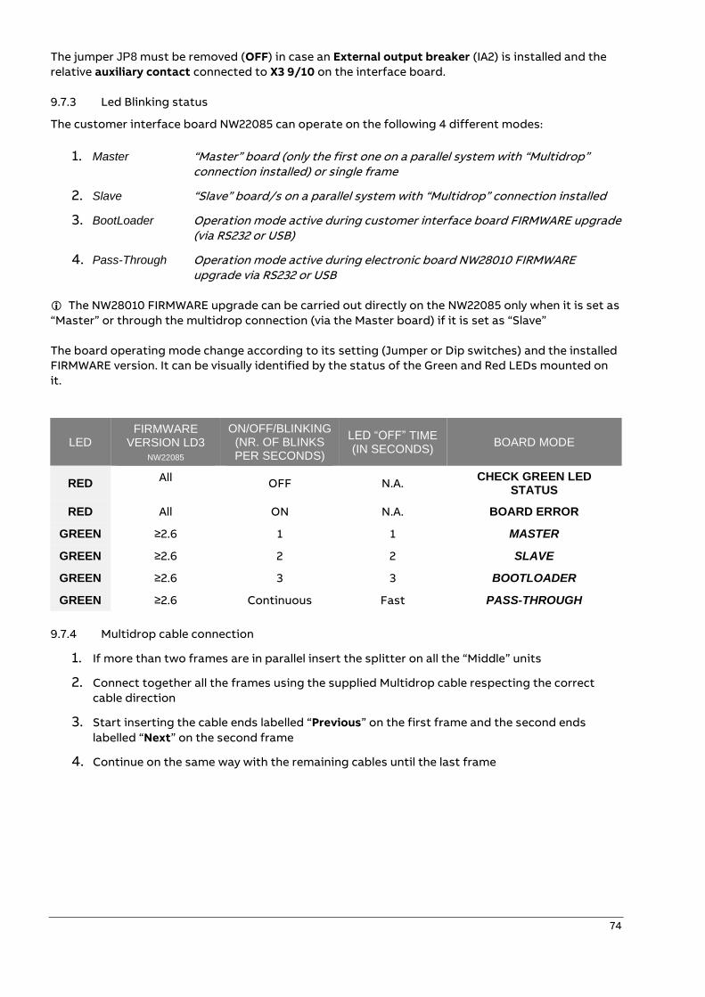
74
The jumper JP8 must be removed (OFF) in case an External output breaker (IA2) is installed and the
relative auxiliary contact connected to X3 9/10 on the interface board.
9.7.3 Led Blinking status
The customer interface board NW22085 can operate on the following 4 different modes:
1. Master “Master” board (only the first one on a parallel system with “Multidrop” connection installed) or single frame
2. Slave “Slave” board/s on a parallel system with “Multidrop” connection installed
3. BootLoader Operation mode active during customer interface board FIRMWARE upgrade (via RS232 or USB)
4. Pass-Through Operation mode active during electronic board NW28010 FIRMWARE upgrade via RS232 or USB
The NW28010 FIRMWARE upgrade can be carried out directly on the NW22085 only when it is set as
“Master” or through the multidrop connection (via the Master board) if it is set as “Slave”
The board operating mode change according to its setting (Jumper or Dip switches) and the installed
FIRMWARE version. It can be visually identified by the status of the Green and Red LEDs mounted on
it.
LED FIRMWARE
VERSION LD3 NW22085
ON/OFF/BLINKING (NR. OF BLINKS PER SECONDS)
LED “OFF” TIME (IN SECONDS)
BOARD MODE
RED All
OFF N.A. CHECK GREEN LED
STATUS
RED All ON N.A. BOARD ERROR
GREEN ≥2.6 1 1 MASTER
GREEN ≥2.6 2 2 SLAVE
GREEN ≥2.6 3 3 BOOTLOADER
GREEN ≥2.6 Continuous Fast PASS-THROUGH
9.7.4 Multidrop cable connection
1. If more than two frames are in parallel insert the splitter on all the “Middle” units
2. Connect together all the frames using the supplied Multidrop cable respecting the correct
cable direction
3. Start inserting the cable ends labelled “Previous” on the first frame and the second ends
labelled “Next” on the second frame
4. Continue on the same way with the remaining cables until the last frame
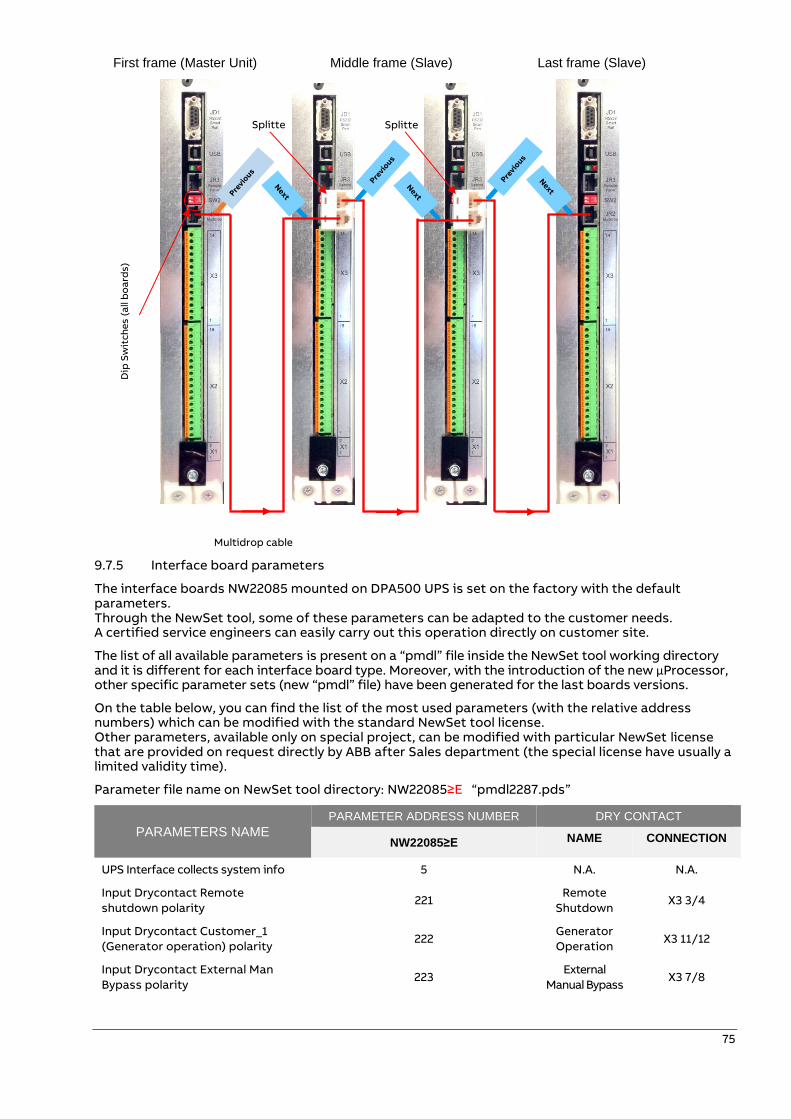
75
First frame (Master Unit) Middle frame (Slave) Last frame (Slave)
9.7.5 Interface board parameters
The interface boards NW22085 mounted on DPA500 UPS is set on the factory with the default parameters. Through the NewSet tool, some of these parameters can be adapted to the customer needs. A certified service engineers can easily carry out this operation directly on customer site.
The list of all available parameters is present on a “pmdl” file inside the NewSet tool working directory and it is different for each interface board type. Moreover, with the introduction of the new µProcessor, other specific parameter sets (new “pmdl” file) have been generated for the last boards versions.
On the table below, you can find the list of the most used parameters (with the relative address numbers) which can be modified with the standard NewSet tool license. Other parameters, available only on special project, can be modified with particular NewSet license that are provided on request directly by ABB after Sales department (the special license have usually a limited validity time).
Parameter file name on NewSet tool directory: NW22085≥E “pmdl2287.pds”
PARAMETERS NAME
PARAMETER ADDRESS NUMBER DRY CONTACT
NW22085≥E NAME CONNECTION
UPS Interface collects system info 5 N.A. N.A.
Input Drycontact Remote
shutdown polarity 221
Remote
Shutdown X3 3/4
Input Drycontact Customer_1
(Generator operation) polarity 222
Generator
Operation X3 11/12
Input Drycontact External Man
Bypass polarity 223
External
Manual Bypass X3 7/8
Splitte
r
Splitte
r
Multidrop cable
Dip
Sw
itc
he
s (
all
bo
ard
s)
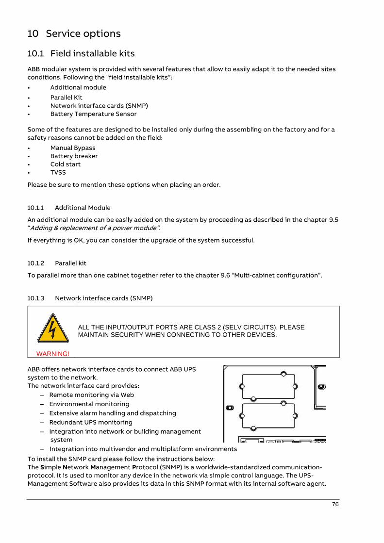
76
10 Service options
10.1 Field installable kits
ABB modular system is provided with several features that allow to easily adapt it to the needed sites
conditions. Following the “field installable kits”:
• Additional module
• Parallel Kit
• Network interface cards (SNMP)
• Battery Temperature Sensor
Some of the features are designed to be installed only during the assembling on the factory and for a
safety reasons cannot be added on the field:
• Manual Bypass
• Battery breaker
• Cold start
• TVSS
Please be sure to mention these options when placing an order.
10.1.1 Additional Module
An additional module can be easily added on the system by proceeding as described in the chapter 9.5
“Adding & replacement of a power module”.
If everything is OK, you can consider the upgrade of the system successful.
10.1.2 Parallel kit
To parallel more than one cabinet together refer to the chapter 9.6 “Multi-cabinet configuration”.
10.1.3 Network interface cards (SNMP)
WARNING!
ALL THE INPUT/OUTPUT PORTS ARE CLASS 2 (SELV CIRCUITS). PLEASE MAINTAIN SECURITY WHEN CONNECTING TO OTHER DEVICES.
ABB offers network interface cards to connect ABB UPS
system to the network.
The network interface card provides:
– Remote monitoring via Web
– Environmental monitoring
– Extensive alarm handling and dispatching
– Redundant UPS monitoring
– Integration into network or building management
system
– Integration into multivendor and multiplatform environments
To install the SNMP card please follow the instructions below:
The Simple Network Management Protocol (SNMP) is a worldwide-standardized communication-
protocol. It is used to monitor any device in the network via simple control language. The UPS-
Management Software also provides its data in this SNMP format with its internal software agent.
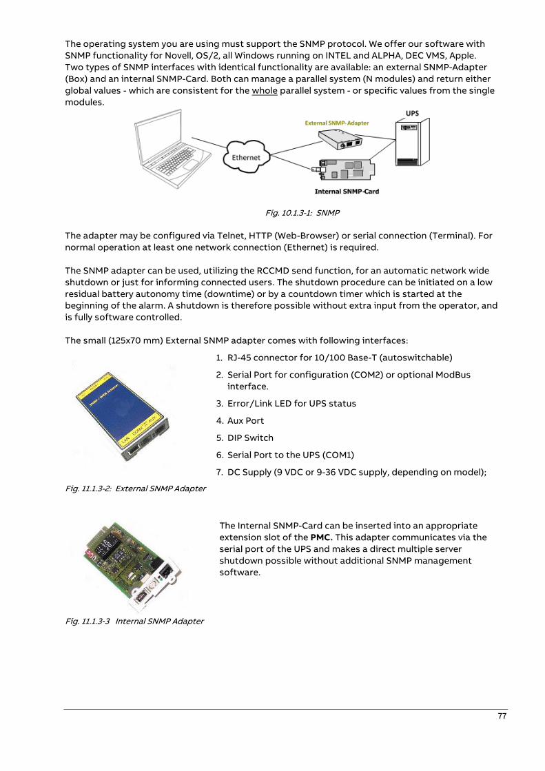
77
The operating system you are using must support the SNMP protocol. We offer our software with
SNMP functionality for Novell, OS/2, all Windows running on INTEL and ALPHA, DEC VMS, Apple.
Two types of SNMP interfaces with identical functionality are available: an external SNMP-Adapter
(Box) and an internal SNMP-Card. Both can manage a parallel system (N modules) and return either
global values - which are consistent for the whole parallel system - or specific values from the single
modules.
Fig. 10.1.3-1: SNMP
The adapter may be configured via Telnet, HTTP (Web-Browser) or serial connection (Terminal). For
normal operation at least one network connection (Ethernet) is required.
The SNMP adapter can be used, utilizing the RCCMD send function, for an automatic network wide
shutdown or just for informing connected users. The shutdown procedure can be initiated on a low
residual battery autonomy time (downtime) or by a countdown timer which is started at the
beginning of the alarm. A shutdown is therefore possible without extra input from the operator, and
is fully software controlled.
The small (125x70 mm) External SNMP adapter comes with following interfaces:
1. RJ-45 connector for 10/100 Base-T (autoswitchable)
2. Serial Port for configuration (COM2) or optional ModBus
interface.
3. Error/Link LED for UPS status
4. Aux Port
5. DIP Switch
6. Serial Port to the UPS (COM1)
7. DC Supply (9 VDC or 9-36 VDC supply, depending on model);
Fig. 11.1.3-2: External SNMP Adapter
The Internal SNMP-Card can be inserted into an appropriate
extension slot of the PMC. This adapter communicates via the
serial port of the UPS and makes a direct multiple server
shutdown possible without additional SNMP management
software.
Fig. 11.1.3-3 Internal SNMP Adapter
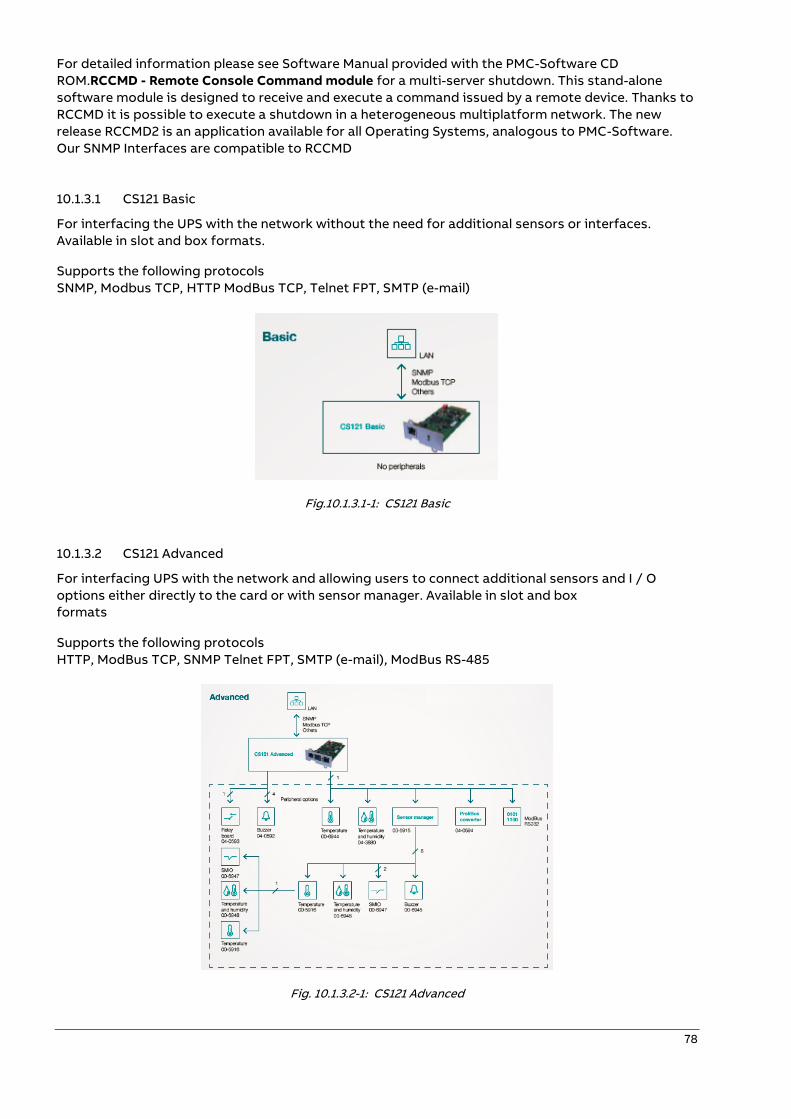
78
For detailed information please see Software Manual provided with the PMC-Software CD
ROM.RCCMD - Remote Console Command module for a multi-server shutdown. This stand-alone
software module is designed to receive and execute a command issued by a remote device. Thanks to
RCCMD it is possible to execute a shutdown in a heterogeneous multiplatform network. The new
release RCCMD2 is an application available for all Operating Systems, analogous to PMC-Software.
Our SNMP Interfaces are compatible to RCCMD
10.1.3.1 CS121 Basic
For interfacing the UPS with the network without the need for additional sensors or interfaces.
Available in slot and box formats.
Supports the following protocols
SNMP, Modbus TCP, HTTP ModBus TCP, Telnet FPT, SMTP (e-mail)
Fig.10.1.3.1-1: CS121 Basic
10.1.3.2 CS121 Advanced
For interfacing UPS with the network and allowing users to connect additional sensors and I / O
options either directly to the card or with sensor manager. Available in slot and box
formats
Supports the following protocols
HTTP, ModBus TCP, SNMP Telnet FPT, SMTP (e-mail), ModBus RS-485
Fig. 10.1.3.2-1: CS121 Advanced
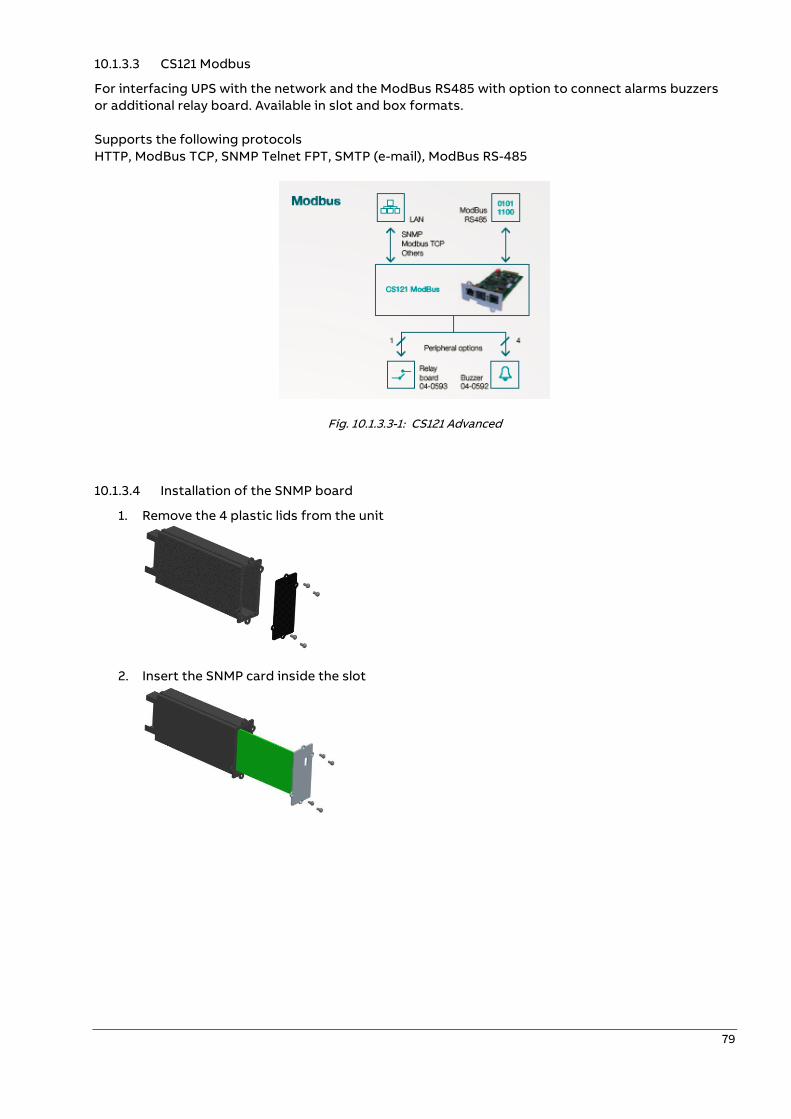
79
10.1.3.3 CS121 Modbus
For interfacing UPS with the network and the ModBus RS485 with option to connect alarms buzzers
or additional relay board. Available in slot and box formats.
Supports the following protocols
HTTP, ModBus TCP, SNMP Telnet FPT, SMTP (e-mail), ModBus RS-485
Fig. 10.1.3.3-1: CS121 Advanced
10.1.3.4 Installation of the SNMP board
1. Remove the 4 plastic lids from the unit
2. Insert the SNMP card inside the slot
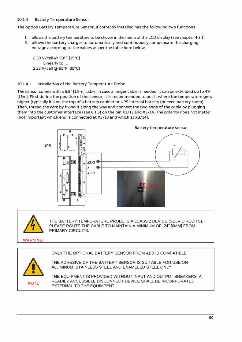
80
10.1.4 Battery Temperature Sensor
The option Battery Temperature Sensor, if correctly installed has the following two functions:
1. allows the battery temperature to be shown in the menu of the LCD display (see chapter 4.3.1)
2. allows the battery charger to automatically and continuously compensate the charging
voltage according to the values as per the table here below.
2.30 V/cell @ 59°F [15°C]
Linearly to …
2.23 V/cell @ 95°F [35°C]
10.1.4.1 Installation of the Battery Temperature Probe.
The sensor comes with a 5.9” [1.8m] cable, in case a longer cable is needed, it can be extended up to 49’
[15m]. First define the position of the sensor, it is recommended to put it where the temperature gets
higher (typically it’s on the top of a battery cabinet or UPS internal battery (or even battery room).
Then, thread the wire by fixing it along the way and connect the two ends of the cable by plugging
them into the customer interface (see 8.1.3) on the pin X3/13 and X3/14. The polarity does not matter
(not important which end is connected at X3/13 and which at X3/14).
Battery temperature sensor
UPS
WARNING!
THE BATTERY TEMPERATURE PROBE IS A CLASS 2 DEVICE (SELV CIRCUITS). PLEASE ROUTE THE CABLE TO MAINTAIN A MINIMUM OF .24” [6MM] FROM PRIMARY CIRCUITS.
NOTE
ONLY THE OPTIONAL BATTERY SENSOR FROM ABB IS COMPATIBLE THE ADHESIVE OF THE BATTERY SENSOR IS SUITABLE FOR USE ON ALUMINUM, STAINLESS STEEL AND ENAMELED STEEL ONLY THE EQUIPMENT IS PROVIDED WITHOUT INPUT AND OUTPUT BREAKERS, A READILY ACCESSIBLE DISCONNECT DEVICE SHALL BE INCORPORATED EXTERNAL TO THE EQUIMPENT.
X3/13
X3/14
T
2-5cm
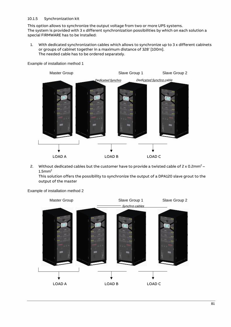
81
10.1.5 Synchronization kit
This option allows to synchronize the output voltage from two or more UPS systems. The system is provided with 3 x different synchronization possibilities by which on each solution a special FIRMWARE has to be installed:
1. With dedicated synchronization cables which allows to synchronize up to 3 x different cabinets or groups of cabinet together in a maximum distance of 328’ [100m]. The needed cable has to be ordered separately.
Example of installation method 1
Master Group Slave Group 1 Slave Group 2
LOAD A LOAD B LOAD C
2. Without dedicated cables but the customer have to provide a twisted cable of 2 x 0.2mm2 –
1.5mm2
This solution offers the possibility to synchronize the output of a DPA120 slave grout to the
output of the master
Example of installation method 2
Master Group Slave Group 1 Slave Group 2
LOAD A LOAD B LOAD C
Synchro cables
Dedicated Synchro cable
Dedicated Synchro cable
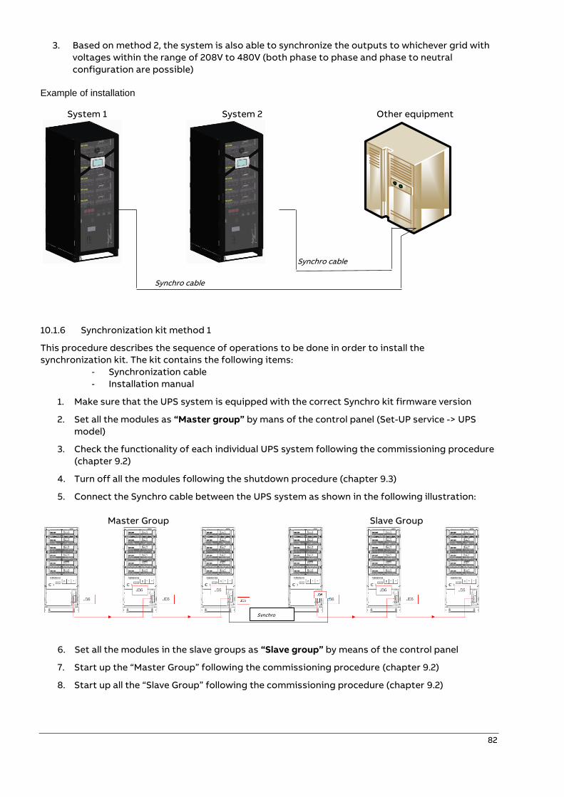
82
3. Based on method 2, the system is also able to synchronize the outputs to whichever grid with
voltages within the range of 208V to 480V (both phase to phase and phase to neutral
configuration are possible)
Example of installation
System 1 System 2 Other equipment
Synchro cable
Synchro cable
10.1.6 Synchronization kit method 1
This procedure describes the sequence of operations to be done in order to install the
synchronization kit. The kit contains the following items:
- Synchronization cable
- Installation manual
1. Make sure that the UPS system is equipped with the correct Synchro kit firmware version
2. Set all the modules as “Master group” by mans of the control panel (Set-UP service -> UPS
model)
3. Check the functionality of each individual UPS system following the commissioning procedure
(chapter 9.2)
4. Turn off all the modules following the shutdown procedure (chapter 9.3)
5. Connect the Synchro cable between the UPS system as shown in the following illustration:
Master Group Slave Group
6. Set all the modules in the slave groups as “Slave group” by means of the control panel
7. Start up the “Master Group” following the commissioning procedure (chapter 9.2)
8. Start up all the “Slave Group” following the commissioning procedure (chapter 9.2)
Synchro cable
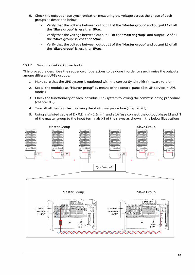
83
9. Check the output phase synchronization measuring the voltage across the phase of each
groups as described below:
- Verify that the voltage between output L1 of the “Master group” and output L1 of all
the “Slave group” is less than 5Vac.
- Verify that the voltage between output L2 of the “Master group” and output L2 of all
the “Slave group” is less than 5Vac.
- Verify that the voltage between output L1 of the “Master group” and output L1 of all
the “Slave group” is less than 5Vac.
10.1.7 Synchronization kit method 2
This procedure describes the sequence of operations to be done in order to synchronize the outputs
among different UPSs groups.
1. Make sure that the UPS system is equipped with the correct Synchro kit firmware version
2. Set all the modules as “Master group” by means of the control panel (Set-UP service -> UPS
model)
3. Check the functionality of each individual UPS system following the commissioning procedure
(chapter 9.2)
4. Turn off all the modules following the shutdown procedure (chapter 9.3)
5. Using a twisted cable of 2 x 0.2mm2 – 1.5mm2 and a 1A fuse connect the output phase L1 and N
of the master group to the input terminals X3 of the slaves as shown in the below illustration:
Master Group Slave Group
Master Group Slave Group
Synchro cable
84
NOTE
THE TWISTED CABLE OF 2 x 0.2mm2 – 1.5mm2 IS NOT PROVIDED IN THE KIT. INSTALLATION SHALL COMPLY WITH THE NATIONAL ELECTRICAL CODE, ANSI/NFPA 70 AND THE CANADIAN ELECTRICAL CODE, PART I, C22.1
6. Set all the modules in the slave system as “Slave group” by means of the control panel
7. Start up the “Master Group” following the commissioning procedure (chapter 9.2)
8. Start up all the “Slave Group” following the commissioning procedure (chapter 9.2)
9. Check the output phase synchronization measuring the voltage across the phase of each
groups as described below:
- Verify that the voltage between output L1 of the “Master group” and output L1 of all
the “Slave group” is less than 5Vac.
- Verify that the voltage between output L2 of the “Master group” and output L2 of all
the “Slave group” is less than 5Vac.
- Verify that the voltage between output L1 of the “Master group” and output L1 of all
the “Slave group” is less than 5Vac.
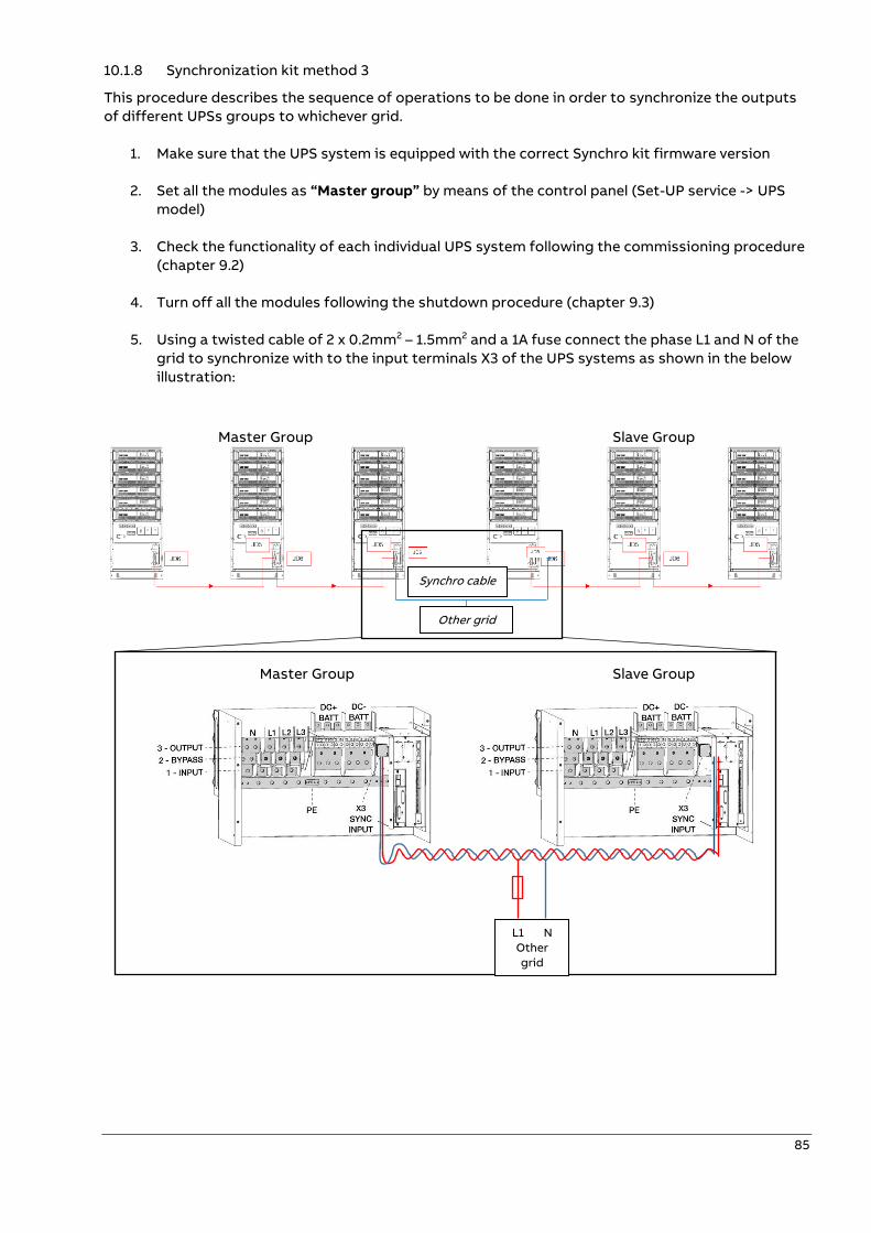
85
10.1.8 Synchronization kit method 3
This procedure describes the sequence of operations to be done in order to synchronize the outputs
of different UPSs groups to whichever grid.
1. Make sure that the UPS system is equipped with the correct Synchro kit firmware version
2. Set all the modules as “Master group” by means of the control panel (Set-UP service -> UPS
model)
3. Check the functionality of each individual UPS system following the commissioning procedure
(chapter 9.2)
4. Turn off all the modules following the shutdown procedure (chapter 9.3)
5. Using a twisted cable of 2 x 0.2mm2 – 1.5mm2 and a 1A fuse connect the phase L1 and N of the
grid to synchronize with to the input terminals X3 of the UPS systems as shown in the below
illustration:
Master Group Slave Group
Master Group Slave Group
Synchro cable
Other grid
L1 N
Other
grid
86
NOTE
THE TWISTED CABLE OF 2 x 0.2mm2 – 1.5mm2 IS NOT PROVIDED IN THE KIT. INSTALLATION SHALL COMPLY WITH THE NATIONAL ELECTRICAL CODE, ANSI/NFPA 70 AND THE CANADIAN ELECTRICAL CODE, PART I, C22.1
6. Set all the modules in the slave system as “Slave group” by means of the control panel
7. Start up the “Master Group” following the commissioning procedure (chapter 9.2)
8. Start up all the “Slave Group” following the commissioning procedure (chapter 9.2)
9. Check the output phase synchronization measuring the voltage across the phase of each
groups as described below:
- Verify that the voltage between output L1 of the “Master group” and output L1 of all
the “Slave group” is less than 5Vac.
- Verify that the voltage between output L2 of the “Master group” and output L2 of all
the “Slave group” is less than 5Vac.
- Verify that the voltage between output L1 of the “Master group” and output L1 of all
the “Slave group” is less than 5Vac.

87
—
11 Attachments
11.1 Technical data sheet
Technical data sheets for the DPA 60 and DPA 120 can be found by visiting the ABB Library, reference
the following links:
Technical Data Sheet: DPA 60
https://search.abb.com/library/Download.aspx?DocumentID=TS-DPA-MK-
0122&LanguageCode=en&DocumentPartId=&Action=Launch
Technical Data Sheet: DPA 120
https://search.abb.com/library/Download.aspx?DocumentID=4NWD003251&LanguageCode=en&Doc
umentPartId=&Action=Launch

— www.abb.com/ups
© Copyright 2020 ABB. All rights reserved. Specifications are subject to change without notice.
—
DP
A 6
0-1
20 U
PS
20-1
20k
W
Related Documents