. 1 INCH-POUND r MIL-C-28876C 18 NOVEMBER 1988 SUPERSEDING MIL-c-28876B 3 February 1987 MILITARY SPECIFICATION CONNECTORS, FIBER OPTIC, CIRCULAR. PLUG AND RECEPTACLE 5TYLE, GENERAL ,This specification is ments and Agencies 1. SCOPE MULTIPLE REMOVABLE TERMINI, SPECIFICATION FOR approved for use by all Depart- of the Department of Defense. 1.1 Scope. This specification covers circular, plug and receptacle style, multiple removable termi.ni, fiber optic connectors that are for Department of Oefense applications and that are compatible with multiple transmission element cables. Fiber optic connectors specified herein cover a family of general purpose, interconnection hardware providing a variety of compatible optical coupling arrangements. 1.2 Classification. Plug and receptacle styles, as specified (see 3.1), shall permit straight, wall mounted., jamnut mounted, right angle and other connector configurations as required for cable system applications. Hardware associated with the connector is also specified (see 3.1), including connector backshells and protective covers. 2. APPLICABLE DOCUMENTS 2.1 Government documents. 2.1.1 Specifications, standards, and handbooks. The following specifications, standards, and handbooks form a part of this document to the extent specified herein. Unless otherwise specified, the issues of these documents are those . listed in the issue of the issue of the Department of Defense Index of Specificatiofis and Standards and supplement thereto, cited in the solicitation. SPECIFICATIONS FEOERAL QQ-P-35, - Passivation Treatments For Corrosion Resisting Steel. QQ-A-225 - Aluminum and Aluminum Alloy Bar, Rod, Wire, Or Special Shapes, Rolled, Drawn, Or Cold Finished, General Specification For. QQ-A-591 - Aluminum Alloy Die Castings. QQ-S-763 - Steel Bar Wire, Shape And Forging, Corrosion Resisting. QQ-S-766 - Steel Plate, Sheet, And Strip-Corrosion Resisting’. lBeneficial comments (recommendations, additions, deletions) and any pertinent i Idata which may be of use in improving this document s~;gjdE~e addressed to: ICommander, Defense Electronics Supply Center, ATTN: 1507 Wilmington lPike, Dayton OH 45444-5276, by using the self-addressed S~an~ardization Document ~ {~g~:~:ement Proposal (DD Form 1426) appearing at the end of this document or by . I AMSC N/A FSC 6060 DISTRIBUTION STATEMENT A. Apprcved for public release; distribution is unlimited. Downloaded from http://www.everyspec.com

Welcome message from author
This document is posted to help you gain knowledge. Please leave a comment to let me know what you think about it! Share it to your friends and learn new things together.
Transcript
.
1 INCH-POUND r
MIL-C-28876C18 NOVEMBER 1988SUPERSEDINGMIL-c-28876B3 February 1987
MILITARY SPECIFICATION
CONNECTORS, FIBER OPTIC, CIRCULAR. PLUG ANDRECEPTACLE 5TYLE,
GENERAL
,This specification isments and Agencies
1. SCOPE
MULTIPLE REMOVABLE TERMINI,SPECIFICATION FOR
approved for use by all Depart-of the Department of Defense.
1.1 Scope. This specification covers circular, plug and receptacle style,multiple removable termi.ni, fiber optic connectors that are for Department ofOefense applications and that are compatible with multiple transmission elementcables. Fiber optic connectors specified herein cover a family of generalpurpose, interconnection hardware providing a variety of compatible opticalcoupling arrangements.
1.2 Classification. Plug and receptacle styles, as specified (see 3.1), shallpermit straight, wall mounted., jamnut mounted, right angle and other connectorconfigurations as required for cable system applications. Hardware associatedwith the connector is also specified (see 3.1), including connector backshells andprotective covers.
2. APPLICABLE DOCUMENTS
2.1 Government documents.
2.1.1 Specifications, standards, and handbooks. The following specifications,standards, and handbooks form a part of this document to the extent specifiedherein. Unless otherwise specified, the issues of these documents are those .listed in the issue of the issue of the Department of Defense Index ofSpecificatiofis and Standards and supplement thereto, cited in the solicitation.
SPECIFICATIONS
FEOERAL
QQ-P-35, - Passivation Treatments For Corrosion Resisting Steel.QQ-A-225 - Aluminum and Aluminum Alloy Bar, Rod, Wire, Or Special
Shapes, Rolled, Drawn, Or Cold Finished, GeneralSpecification For.
QQ-A-591 - Aluminum Alloy Die Castings.QQ-S-763 - Steel Bar Wire, Shape And Forging, Corrosion Resisting.QQ-S-766 - Steel Plate, Sheet, And Strip-Corrosion Resisting’.
lBeneficial comments (recommendations, additions, deletions) and any pertinent iIdata which may be of use in improving this document s~;gjdE~e addressed to:ICommander, Defense Electronics Supply Center, ATTN: 1507 WilmingtonlPike, Dayton OH 45444-5276, by using the self-addressed S~an~ardization Document ~{~g~:~:ement Proposal (DD Form 1426) appearing at the end of this document or by
. I
AMSC N/A FSC 6060DISTRIBUTION STATEMENT A. Apprcved for public release; distribution is unlimited.
Downloaded from http://www.everyspec.com
MIL-C-28876C
MILITARY
MIL-S-901
MIL-H-5606
MIL-L-7808
MIL-R-25988
MIL-T-29504
DOO-F-49291MIL-C-55330DOD-C-85045
(See supplement 1
STANDARDS
MILITARY
I4IL-STD-105
MIL-STO-202
MIL-STD-454MIL-STD-889MIL-STO-1285
Shock Tests, HI (High-Impact) Shipboard Machinery,Equipment And Systems, Requirements For Navy.Hydraulic Fluid, Petroleum Base, Aircraft, Missile, andOrdnance.Lubricating Oil, Aircraft Turbine Engine, Synthetic ‘Base, NATO-Code-Number 0-148.Rubber, Fluorosil icone Elastomer, Oil-and-Fuel-Resistant, Sheets, Strips, Molded Parts, And ExtrudedShapes.Terminii Fiber Optic Connector, General SpecificationFor. -Fiber, Optical, (Metric), General Specification For.Connector, Electrical and Fiber Optic, Packaging of.Cable, Fiber Optics, (Metric), General Specification For.
for list of associated specifications.)
Sampling Procedures and Tables For Inspection ByAttributes.Test Methods for Electronic And Electrical ComponentParts.Standard General Requirements For Electronic Equipment.Dissimilar Metals.Marking of Electrical And Electronic Parts.
MIL-STD-1344 - Test Methods For Electrical Connectors.MIL-STD-1373 - Screw Thread, Modified, 60 Degree Stub, Oouble.DOD-STD-1678 - Fiber Optics Test Methods And Instrumentation.MIL-STD-2163 - Insert Arrangements For MIL-C-2B876(NAVY) Environment
Resisting Fiber Optic Connectors.MIL-STO-45662 - Calibration Systems Requirements.
(Unless otherwise indicated, copies of federal and military specifications,standards, and handbooks are available from the Naval Publications and FormsCenter, (ATTN: NPOOS), 5801 Tabor Avenue, Philadelphia, PA 19120-5099). )
2.2 Non-Government publications. The following documents form a part of thisdocument to the extent specified herein. Unless otherwise specified, the issuesof the documents which are 00D adopted are those listed in the issue .of the 00DISScited in the solicitation. Unless otherwise specified, the issues of thedocuments not listed in the 0001SS are the issues of the documents cited in thesolicitation (see 6.2).
ELECTRONIC INDUSTRIES ASSOCIATION (EIA)
tEIA-RS-359tEIA-RS-455
tEIA-RS-455-l -
tEIA-RS-455-22 -tEIA-RS-455-40 -tEIA-455-2IEIA-455-4tEIA-455-13
tEIA-455-21
EIA Standard Colors for Color Identification and Coding.Standard Test Procedures for Fiber ’Optic Fibers, Cables,Transducers, Connecting” and Terminating Devices.Standard Test Procedures for Fiber Optic Fibers, Cables,Transducers, Connecting and Terminating Devices (FOTP-3).Ambient Light Susceptibility.Fluid Immersion Test for Fiber Optic Cable.Impact Test Measurements for Fiber Optic Oevices.Fiber Optic Connector/Component Temperature Life.Visual and Mechanical Inspection of Fibers, Cables,Connectors, and/or Other Fiber Optic Oevices.Mating Durability for Fiber Optic Interconnecting Oevices.
2
Downloaded from http://www.everyspec.com
MIL-C-28876C
+EIA-455-26 Crush Resistance of Fiber Optic Interconnecting Devices.tEIA-455-32 Fiber Optic Circuft Discontinuities.+EIA-455-34 - Interconnection Device Insertion Loss Test.tEIA-455-36 Twist Test for Fiber Optic Connecting Devices.
tOenotes adopted EIA documents.
(Application for copies should be addressed to the Electronic IndustriesAssociation, Engineering Department, 2001 Eye Street, N.Ii., Washington, OC 20006.)
(Non-Government standards and other publications are normally available from theorganizations that prepare or distribute the documents. These documents also maybe available in or through libraries or other informational services.)
2.3 Order of precedence. In the event of a conflict between the text of thisdocument and he references cited herein (except for related associated detailspecifications, specification sheets, or MS standards), the text of this documenttakes precedence. Nothing in this document, however, shall supersede applicablelaws and regulations unless a specific exemption has been obtained.
3. REQUIREMENTS
3.1 Specification sheets. The individual connector requirements shall be asspecified herein and in ac~ordance with the applicable specification sheets. Inthe event of any conflict between the requirements of this specification and thespecification sheet, the latter shall govern.
3.2 Qualification. Fiber optic connectors and accessories furnished under thisspecification shall be products which are qualified for listing on the applicablequalified products list at the time set for opening of bids (see 4.4 and 6.3).
3.3 Materials. The connectors, backshells, covers, or other protectiveaccessory hardware shall be constructed of:
a. Aluminum alloy per QQ-A-225, or QQ-A-591.
b. Stainless steel per QQ-S-763, class 316.
c. Stainless steel per QQ-S-763, class 302 through cla$$ 304.
d. Stainless steel per QQ-S-766, class-302.
e. Fluorosilicone per MIL-R-25988, type 1, class 1, grade”60.
f. Fluorosilicone per MIL-R-25988, type l,”class 1, grade 70.
. 3.3.1 Finish. The resultant finish on all connectors, backshells, covers,’orother pro~e accessory hardware shall be as follows:
a. Aluminum components: Cadmium plate, olive drab over electroless nickelfor external parts. Gray anodize for internal parts.
b. Stainless steel components, passivate per QQ-P-35.
3.3.2 General. All materials used shall be nonmagnetic and nonnutrient tofungus (see requirement 4 of MIL-STO-454). Materials may be dielectric orconductive as applicable. Materials shall in no manner interfere with or degradethe fiber optical termination process, contact cleaning operation or opticaljunction transmission.
Downloaded from http://www.everyspec.com
6
MIL-C-28876C
3.3.3 Solvents, adhesives, and cleaning agents. No incompatibility shall existbetween the materials employed in th fib t terminus securing or polishingprocesses, such that degradation of ~hesee~at~rials shall result from in-serviceuse or when tested in accordance with the requirements of the temperature llfetest of 3.11.10.
3.3.3.1 Recommended solvents, adhesives, and cleaning agents. The connectormanufacturer shall paqk with each connector, a ist of the solvents, adhesives,and cleaning agents, as applicable, recommended for use with the connector.
3.3.3.2 Recommended cleaning procedure. The connector manufacturer shall packthe recommended terminus cleaning procedure with each connector.
3.3.4 Toxic and hazardous products and formulations. Materials used in theconnectors, baCk5hellS, or accessories shall not give off toxic or explosive fumeswhen exposed to flame. Materials used shall have no adverse effect on the healthof personnel when used for its intended purpose.
c~;~;;on%%%%”Unless otherwise specified (see 3.1), all expo$ed
steel parts of the connector assembly shall have a passivatedffnish which permits the attainment of a surface finish condition compatible withexternal coatings of platings of the type and color specified herein.
3.4 Design and construction. Connectors, backshells, and protectiveaccessories shall contorm to Tigures 3 through 10, and as specified (see 3.1).
3.4.1 Dissimilar metals. Intimate con,tact between dissimilar metals shall beavoided, w ere poss e,~n connectors designed to this specification. Shouldcontacting dissimilar metals be employed in a connector, suitable protectionagainst electrolytic corrosion shall be provided as specified in MIL-STD-889.
3.4.2 Seals. Seals shall provide environmental isolation for the opticalcontact j~ons and connector interior parts. Grommets, O-rings, fnterfacialseals, boots, gaskets, or other sealing devfces, as needed by the connectordesign, shall accomplishtheir intended purpose and meet all test requirements as specified herein.
3,4,2.1 Optical junctfon sealfn Optical junctions shall be sealed agafnstmoisture and contamination as spec
3the
3sha’
● 3rep’
4.2.2 Cable sealing. Connectors shall seal the terminating cables to meetenvironmental requirements specifted herein.
4.3 Interchangeability and intermateabflity. Connector material and hardware1 be as specified (see J.1), to insure interchangeability and intermateability.
4.3.1 Interchangeabf lft~. All connectors, backshells, accessories, andaceable Darts havlna he same mflftary Dart number shall be Physically and
functional ly’lnterc,hang;abl e without need-for modification of such-items ~r of themating equipment.
3.4.3.2 Intermateability. All connectors having the same termini, insertarrangement, and shell size shall be interrnateable with thefr counterpartconnectors.
3.5 Connectors (receptacles and plugs).
3.5.1 Shells. The connector shells shall retain the connector insert.
3.5.1.1 Receptacles. Receptacles shall be of the wall mount, jamnut, or cabletypes as specified (see 3.1).
4
Downloaded from http://www.everyspec.com

MIL-C-28876C
3.5.1.2 Engagement of connectors. Counterpart connectors of any arrangementand accessories shall be capable of being fully engaged and disengaged without theuse of tools.
3.5.1.3 Coupling mechanism. Coupling rings’of the connectors shall be knurled,and designed so that plug and receptacle optical termini shall approach or recedefrom each other as the coupling mechanism is respectively tightened by clockwiserotation or loosened in the counterclockwise direction as viewed from rear of plugconnector. The coupling mechanism shall be captive on the plug to mate with thereceptacle shell. Coupling ring and coupling screw threads shall be in accordancewith MIL-STD-1373 as shown on figures 6 and 7, and as specified (see 3.1). If thecoupling threads must be lubricated to meet the requirements contained herein, thelubricant, shall be applied only during manufacture. The lubricant selected shallnot be reapplied nor migrate into the optical junction region during use.
3.5.1.4 Shell and backshell polarization (keying). The polarization of themating plug and receptacle shall be accomplished by integral keys on plug andreceptacle shells. Keys shall be designed to prevent physical contact of themating optical termini or of the termini with the insert surface of thecounterpart connector until the keyways are properly aligned for engagement andthe coupling mechanisms are engaged. 8ackshell splines, keys, and keyways shallbe polarized and mated prior to coupling.
3.5.2 Termini. All termini requirements shall be in accordance withMIL-T-295~ 3.1).
3.5.3 Inserts. Inserts shall be keyed and secured to prevent rotation withinthe connector shell.
3.5.3.1 Number of termini, arrangement, and spacin The insert pattern, thatis, the number of termini, their arrangement and spat g shall be as specified inMIL-STD-2163. Every terminus position shall accept either optical or dummytermini. Termini spacing shall permit adequate terminus marking identificationand easy terminus insertion and removal.
3.5,3.2 Terminus insertion and removal methods. Optical terminus insertionshall be accomplished by inserting the terminus and the terminus insertion toolinto the rear of the connector and by locking the terminus in place. Opticalterminus removal shall be accomplished by inserting the terminus removal tool intothe front of the connector and by forcing the terminus out the rear of theconnector. The individual termini shall be positively retained in the connectorwhen installed with the terminus insertion tool and shall be capable of beingremoved without terminus or insert damage when using the terminus removal tool.Requirements for these tools shall be as specified (see 3.1).
3.6 Backshell accessories. Backshells shall conform to the requirements as. specified (see 3 he backshells shall be provided with or without cable
strain relief. ~he”backshells shall be free of any sharp edges or otherconfigurations that could cause damage to optical fibers extending through them.
3.7 Protective caps. All optical connectors (plugs and receptacles) shall beprovided with a plastfc throw-away protective cap or cover. The cover shall befree of mold release or any other lubricants.
3.8 Tools. Tool”s used to terminate connectors onto cables shall be asspecifi~ee 3.1). The connector manufacturer shall provide the tools whenspecified in the acquisition documents (see 6.2).
Downloaded from http://www.everyspec.com

MIL-C-28876C
.
3.9 Visual and mechanical inspection of fibers, cables, connectors, or otherfiber optic devices.
3.9.1 Size. Uhen examined in accordance with 4.6.1, the dimensions anddimensi onfiolerances for these connectors, backshells, and accessories shall beas specified (see 3.1).
3.9.2 Mass. When tested in accordance with 4.6.2, the mass,of the connectors,backshell~nd accessories shall be as specified (see 3.1,).
3.9.3 Identification marking. Marking characters shall be a minumum of .040inch in height. The connector shall also be marked with a yellow band inaccordance with EIA RS-359, and the phrase “FIBER OPTICS” as s ecified (see 3.1).
!When tested in accordance with 4.6.3, the connectors, backshel s, and accessoriesshall be marked as specified in 3.9.3.1, 3.9.3.2, or as s ecified (see 3.1).
!All
marking characters in any face of the connectors, backshe 1s, or accessories shallbe identifiable.
3.9.3.1 Connectors, backshells, and accessories. The connectors, backshells,and accessory parts shall be identif ied by a legible and permanent marking appliedin accordance with MIL-STD-1285.
3.9.3.2 Inserts. Marking shall correspond between mating inserts and shall beas specifie~L-STD-2163. Raised or depressed characters shall not be used onmating faces. Terminus locations shall be designated by identifiable characterson the front and rear faces of the insert or the insert assembly. Characterposition and arrangement shall assure appropriate terminus cavity identification.
h~k’~~ad-:All details of workmanship shall be in accordance with the
1 er op lC connector manufacturing practice when examined inaccordance with 4,6.4. Connectors and accessories shall be dimensionally uniformand free of manufacturing flaws that would degrade performance, inhibit properconnection to interfacing elements, and otherwise yield an inferior product.. Thefollowing shall be a minimal level of visual examination to be performed and isnot intended to restrict other pertinent workmanship examinations:
a. Loose contacts, inserts, or other connector parts which adversely effectthe environmental sealing, permit cable sealant penetration or degradeoptical contact alignment shall not be permitted.
b. Peeling or chipping of plating or finish, galling of mating partsindicating excessive wear, nicks, burrs, or other substandard connectorsurface blemishes shall not be permitted.
3.10 Optical performance. The optical performance requirements of 3.10.1throu h
?3105h”be used to monitor effects of the inspection requirements
speci led”in”3.$ is requiyed by 4.4.2, 4.5.1.2, and 4.5.2.
3.10.1 Interconnection device insertion loss test. When measured in accordancewith 4.7.1, he maximum per channel insertion loss under all conditions shall be1.5 decibels (dB) for core fibers of 100 micrometers (#m) and 2.0 dB for 50-wmcore fibers.
3.10.2 Fiber optic circuit discontinuities. Uhen measured in accordance with4.7.2, no discontinuity shall occur. A discontinuity is considered to be areduction of strength of 2 dB (37 percent) or more for a duration of 1 microsecond(us) or longer.
3.10.3 Analog modulation. When tested in accordance with 4.7.3, thepeak-to-peak analog modulation, bandpass limited to between 4 hertz (Hz) and 40kilohertz (kHz), shall be not more than 1 percent of the steady-state signal level.
Downloaded from http://www.everyspec.com

:..“
MIL-C-28876C
3.10.4 Crosstalk. When devices with 3 or more channels are tested inaccordance with 7.4, the signal power levels, or sum of levels of the passivechannel or channeis, shall be below the signal level of the active channel by atleast 60 dB.
3.10.5 Ambient light susceptibility. When tested in accordance with 4.7.5, theoptical power ot he i19ht from he optical ports (after accounting for cable andoptical junction losses between the device and the detector) shall be less than-70 dBm.
3.11 Physical requirements.
3.11.1 Screw threads. When tested in accordance with 4.8.1, slightout-of-roundness beyond the tolerances specified is acceptable if the threads canbe checked without forcing the thread gauges. Screw threads may be relievedprovided the relief does not interfere with proper performance of the screwthreads.
3.11.2 Terminus insertion and removal forces. Connectors shall be tested inaccordance with 4 8 he terminus insertion force and the force required toremove unlocked t~r~i~i shall not exceed 22.0 pounds.
3.11.3 Terminus retention force. When tested in accordance with 4.8.3 andsubjected to axial loads of pounds termini shall be retained in their insertsand axial displacements of the”termini shall not exceed 0.015 inch (0.38 mm).
3.11.4 Insert retention axial strength. When tested in accordance with 4.8.4,connector inserts shall withstand an applied minimum pressure of 100 pounds persquare inch in both the forward direction and the backward direction for a minimtimperiod of 1 minute without cracking, breaking, or being dislocated from theirnormal positions in the connector shell. No axial displacement detrimental toperformance shall be observed between the inserts and their shell body during orafter the test exposure.
3.11.5 Insert retention radial strength. Iihen tested in accordance with 4.8.5,connector inserts shall withstand the clockwise and counterclockwise radial torquespecified in table I for a minimum period of one minute. No rotationaldisplacement detrimental to performance shall be observed between the inserts andtheir shell body during or after the test exposure.
TABLE I. Insert retention radial strength.
7 I rI Connector shell size I Maximum radial torque II I (inch pounds) I
, i 11 i 15I I !
i 13 i 20 I
i 15 i 25 i
3.11.6 Cable retention test procedure for fiber optic cable interconnecting.devices. When tested in accordance with 4 8.6, the minimum cable to connector~ strength shall be 162 pounds. The~e shall be no evidence of cable jacketdamage, cable clamp failure, cable to connector seal damage, distortion or bendingof metallic connector parts, or cable disengagement from the clamp.
I
7
Downloaded from http://www.everyspec.com
MIL-C-28876C
3.11.7 External bending moment. When testedconnectors shall exhibit no visible evidence ofability to perform as specified (see 3.1).
in accordance with 4.8.7,damage that may degrade their
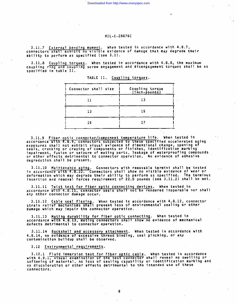
3.11.8 Coupling torques. When tested in accordance with 4.8.8, the maximumcoupling r~ng and coupling screw engagement and disengagement torques shall be asspecified in table II.
TABLE II. Coupling torques.
1 I 1-1 Connector shell size I Coupling torque I
I (inch-pounds) I1I 11 13 II / I
\ 13 i 15 II I
1I 15 I 17 I
3.11.9 Fiber optic connector/component temperature life. Mhen tested inaccordance with 4.8. 9, connectors subJected to these specffied accelerated aging%#oiures shall not exhibit visual evidence of dimensional change, opening of
cracking or crazing of components or finishes, identification markingimpai~ment, fusion or seizure of mating parts, leakage of waterproofing compoundsor other effects detrimental to connector operation. No evidence of adhesivedegradation shall be present.
3.11.10 Maintenance aging. Connectors with removable termini shall be testedin accordance with 4 8 10 Connectors shall show no visible evidence of wear ordeformation which ma; ~eg~ade their ability to perform as specified. The terminusinsertion and removal forces requirement of 22.0 pounds (see 3.11.2) shall be met.
3.11.11 Twist test for fiber optic connecting devices. When tested inaccordance with 4.8.1 1, connector seals shall not be rendered inoperable nor shallany other connector damage occur.
3.11.12 Cable seal flexin Uhen tested in accordance with 4.8.12, connectorstrain relief mechanisms sha -prevent loss of environmental sealing or otherdamage which may impair the connector operation.
3.11.13 Mating durability for fiber optic connecting. When tested inaccordance with 4.8.13 mating connectors shall show no evidence of mechanicaldefects detrimental to’connector operation.
3.11.14 Backshell and accessory attachment. When tested in accordance with4.8.14, no evidence of excessive thread binding, seal pinching, or anycontamination buildup shall be observed.
3.12 Environmental requirements.
3.12.1 Fluid immersion test for fiber optic cable. When tested in accordancewith 4.9.1, visual examinatf on of the test connector shall reveal no swelling orsoftening of material, no loss of sealing capability or identification marking andno discoloration or other effects detrimental to the intended use of theseconnectors.
8
Downloaded from http://www.everyspec.com
MIL-C-28876C
3.12.2 Temperature cycling of ffber optic connectors (thermal shock). Whentested in accordance with 4.9.Z, a posttest visual examination of the testconnectors shall reveal no evidence of connector part dimensional change, noleakage of waterproofing compounds or other apparent loss of sealing capability,no surface or identification marking impairment, no couplfng-thread binding orother evidence of mating or unmatfng incapability, and no other damage detrimentalto the operation of the connector.
3.12.3 Mechanical shock. When tested in accordance with 4.9.3, connectorsshall not be damaged and there shall be no loosening of parts.
3.12.4 Vibratfon test procedures for fiber optic connecting devices. Whentested in accordance with 4.9.4, connectors shall not exh ibit visual evidence ofloosening of parts, relative motion between parts or other damage which canproduce physical distortion or wear and may result in fatigue of the mechanicalparts or failure of the connector operation.
3.12.5 Ozone exposure. When tested in accordance wfth 4.9.5, seals shall showno evidence o? excessive swelling or embrittlement which may degrade environmentalisolation.
3.12.6 Water pressure. When tested in accordance with 4.9.6, visual inspectionof the test connector shall reveal no penetration of indicator dye into the sealedregion of the mated connector.
3.12.7 Impact test measurements for fiber optic devices. When tested inaccordance with 4.9.7, connectors shall not be visib ly damaged or otherwiserendered unfit for operational use.
3.12.8 Crush resistance. When tested in accordance with 4.9.8, connectorsshall show no evidence of inabflity to mate or unmate, broken parts,. backshells oraccessories, loss of optical continuity, or damage to shells.
3.12.9 Humidity test procedure for fiber optic connecting devices. When testedin accordance with 4.9.9 , connector parts shall not swell or otherwfse degradesuch that connector performance is impafred.
3.12.10 Salt spray (corrosion). When tested fn accordance with 4.9.10, novisible evfdence of salt penetration into the connector sealed area shall beobserved. No corrosive effects shall be seen on the external connector partswhich would be detrimental to the operation of the connector.
~ 3.12.11 Sand ”and dust. When tested in accordance with 4.9.11, the connectorsshall show no evidence of physical damage which will adversely affect theoperation of the connector and shall have insertjon losses and coupling torqueswithin the requirements of 3.10.1 and 3.11.8.
,3.12.12” Terminus cleaning. After cleaning the terminus in accordance with
4.9.12, the marking requirements of 3.9.3 and the optical insertion loss of 3.10.1shall be met.
3.12.13 Flammability=11-#”
Uhen tested in accordance wfth 4.9.13, burning andafterglow ext ngu s lng time shall be 3 seconds. Drippfng which will causeflammable material to ignite and violent burning or an explosive type fire shallnot occur.
Downloaded from http://www.everyspec.com
MIL-C-28876C
4. QUALITY ASSURANCE PROVISIONS
4.1 Responsibility for inspection. Unless otherwor Durc%ase order, the contractor is responsible forinspection requirements as specified herein. Exceptcontract or purchase order, the contractor may use h’suitable for the performance of the inspection requilunless disapproved by the Government. The Governmen’perform any of the inspections set forth in the spec’inspections are deemed necessary
se specified in the contractthe performance of allas otherwise specified in thes own or any other facilitiesements specified herein,reserves the right to
fication where such
to assure supplies and services conform to prescribed requirements.
4.1.1 Responsibility for compliance. All items must meet all requirements ofsections and 5. The inspections set forth in this specification shall become apart of the contractor’s overall inspection system or quality program. Theabsence of any inspection requirements in the specification shall not relieve thecontractor of the responsibility of assuring that all products or suppliessubmitted to the Government for acceptance comply with all requirements of thecontract. Sampling in quality conformance does not authorize submission of knowndefective material, either indicated or actual, nor does it commit the Governmentto acceptance of defective material.
4.1.2 Test equipment and inspection facilities. Provisions for test andmeasuring equipment and inspection facillti es ot sufficient accuracy, quality andquantity to permit performance of the required inspections shall be theresponsibility of the contractor. The establishment and maintenance of acalibration system to control the accuracy of the measuring and test equipmentshall be in accordance with MIL-STD-45662 and as specified herein.
4.1.3. Assembly plants.’ Assembly plants must be listed on, or approved forlisting on, th e appli cable qualified products list. The qualified connectormanufacturer shall certify that the assembly plant is approved for thedistribution of the manufacturer’s parts. The assembly plant shall use only pieceparts supplied by the qualified connector manufacturer. No testing other thanvisual examination is required of certified piece parts obtained from thequalified connector manufacturer, except when there is cause for rejection. Allassemblies produced at the assembly plant shall be subjected to examination of theproduct to assure that the assembly process conforms with that established at thequalified manufacturing plant. Quality control requirements, including Governmentinspection surveillance, shall be the same as required for the qualified connectormanufacturer.
4.2 Inspections.
4.2.1 Classification of inspections.classified as foil Ows:
a. Materials inspection (see 4.3).
b. Qualification inspection (see 4
c. Quality conformance inspection
The inspections specified herein are
4).
see 4.5).
4.2.2 Inspection conditions. Unless otherwise specified, all inspections shallbe performed in accordance with the test conditions specified in DOD-STD-1678.
4.3 Materials inspection. Materials inspection shall consist of certificationsupported by verifying data that materials used in fabricating the delivered fiberoptic connectors are in accordance with the requirements of 3.3 and as specified(see 3.1).
10
Downloaded from http://www.everyspec.com
MIL-C-28876C
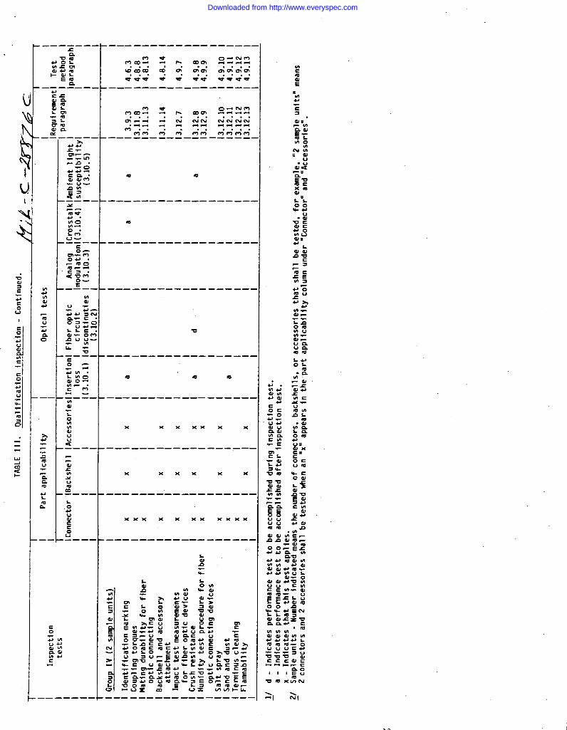
4.4 Qualification inspection. Qualification inspection shall be performed at alaboratory acceptable to the Government (see 6.3) on sample units produced withequipment and procedures normally used in production. This inspection shallconsist of performing the inspections and optical tests specified in table III, inthe sequence shown therein, on the qualification test samples specified in 4.4.1.
4.4.1 Test sam les.~
Fiber optic connector, backshell, and accessory samplescomplying wlt the specified requirements (see 3.1) shall be submitted forqualification. The manufacturer shall provide a counterpart connector for eachconnector subjected to qualifying tests requiring mating assemblies. Thecounterpart connectors provided for this purpose shall be new, previouslyqualified connectors or new connectors submitted for qualification testing.Manufacturers not producing mating connectors shall submit data substantiatingthat tests were performed with qualified counterpart connectors. For those testsspecifying the use of mated connectors, optical and mechanical test assessmentssha?l be made using the assigned counterpart connector for those test measurementsas required.
4.4.1.1 Sample size. Six mating pairs, individual connectors shall besubmitted for qualif ication testing. These connectors shall consfst ofMIL-C-28876/2 wall-mounted receptacles with straight strain reliefs andMIL-C-28876/7 plugs wfth straight strain reliefs as specified (see 3.1).
4.4.1.2 Sample preparation. Unless otherwise specified, connectors shall befully assem~led Into cabl e-connector assembles using the types of cable specifiedin the applicable connector specification sheet (see 3.1). Connector terminalsshall be optically finished with termini properly seated within their inserts.For mated connectors, full sealing capability shall be provided as specffied.Connectors shall be provided wfth backshell, strain relief cable clamp, andattached to a 15-meter length of the, specified cable type.
4.4.2 Inspection routine. Connector, backshell, and accessory samples shall betested in accordance with the sequence of table III. Optical tests shall be madeas specified in table III. The connector group samples may be testedsimultaneously.
4.4.3 Qualification rejection. Qualification approval will not be granted ifany of the connectors, backshells, or accessories being tested according to tableIII fail to meet the requirements of 3.3, 3.4-, 3.9, 3.10, 3.11, and 3.12.
4.4.4 Retention of qualification. To retain qualification, the contractorshall forward a report at 18-month intervals to the qualifying actfvity. Thequalifying activity shall establish the initial reporting date. The report shallconsist of:
a. A summary of the results of the tests performed for inspection of productfor delfvery (group A), indicating as a minimum the number of lots thathave passed, the number that have failed, and the group which theyfailed. The results of tests of all reworked lots shall be identifiedand accounted for.
b. A summary of the results of tests performed for periodic inspection(group B), including the number and mode of faflures. The summary shallinclude results of all periodic inspection tests performed and completedduring the 18-month period. If the summary of the test results indicatesnonconformance with specification requirements, and corrective actionacceptable to the qualifying activity has not been taken, action may betaken to remove the failing product from the qualified products list.
11
Downloaded from http://www.everyspec.com

.-— ——--
}-——— ————— —————————— ——— —___ ____ ____ —___ ____ _—_—_— ———.
.—— - ——————-— ————— ———- ——-- —--- ———— —-—— —___—_ —____ ____
.—— —- -————— -————_ —--—— ——_—_ ——-—— ——————_— ————_ —____ _.
.—_— ——-——- _—— —_— ————_— _- ____ ——————_— ————— —_—_—_ —___ _
.—— —————— ———————- ———————_ —_—— ——-— ———— —_—— —_—_ -— __ ___\-1 m m a-a vx
.—— ————-—-_—_ —-—— ——___ —__— —___ _—_— ——_ —___ ---- —-—_ _— _
XX xxx x xxx x xx x
.—_— — ————— -———————— —_-_ —_ —__ —— _- ———— ——__— -_—_— -— _- __
XX xxx x xxx Xxx xxx xxx%
,-— — —-—— —-— ——— ——— ——— -—— ___ ___ -_— ___ —__ ___ __— —_- ___ _
Xxxx xxx x Xxxxx xxx x Xxxxxx xxx Xxxx
,—————— ——__ ——- ————_— ______ —___ —_— _—— _ ___ _— __ ____ ___ _
——— .- .- _—————— -— —-- -———— ————— ————- ___— —_____ _____ _____ ____ _
12
Downloaded from http://www.everyspec.com
I
.
.—— ———-. .— —-— ————— —————___
——————.
.—-— —————— -————— —.
,—-— ——-———— ———— ——-
W
,— __ __— —_ ___ ——_ ___
—————-——— ——-- -——-
U
————— -————— ———— --
1m m Iv
—————— —— -- ———— ———
x Xxx xxx
———— ————— ———- —-——
x x%x x x
-—--— -—————— ———- -
XXxx xxx Xxxx
——-— -——— ———— —-—— -
*wu
———- ———————— -——- — \ \-1 -J I
Downloaded from http://www.everyspec.com
MIL-C-28876C
.
Failure to submit the report within 30 days after the end of each 18-month periodmay result in loss of qualification for the product. In addition to the periodicsubmission of inspect~on data, the contractor shall immediately notify thequalifying activity at any time during the 18-month period that the inspectiondata indicates failure of the qualified product to meet the requirements of thisspecification.
In the event that no production occurred during the reporting period, a reportshall be submitted certifying that the company still has the capabilities andfacilities necessary to produce the item. If during two consecutive reportingperiods, there has been no production, the manufacturer may be required, at thediscretion of the qualifying activity, to submit the qualified product to testingin accordance with the qualification inspection requirements.
4.4.5 Qualification of additional connectors. Qualification of wall-mountedreceptacles shall aualify cabl e-connecting and jamnut mounted receptacles. Eachshell size shall ,be qual~fied separately.- Qualification of one backshell shallqualify all backshells of the same shell size.
4,5 Quality conformance inspection. Quality conformance inspection shallconsist of the inspections and optical tests specified for group A inspection(table IV), group B inspection (table V), and packaging inspection.
4.5.1 Inspection of product for delivery. Inspection of product for deliveryshall consist ot group h inspection.
4.5.1.1 Inspection lot. The inspection lot shall consist of the number ofconnectors of fered for inspection at one time, and all of the same design ascovered by one specification sheet.
4.5. 1.1.1 Sample unit. A sample unit shall be selected at random from theinspection lot.
4.5.1.1.2 Sample size. The sample size shall consist of that number of sampleunits required by the inspection lot size, as determined by the sampling plans inMIL-STD-105.
4.5.1.2 Group A inspection. Group A inspection shall consist of the inspection,tests specified in table IV All connectors, backshells, and accessories of theinspection sample shall be ~ubjected to the inspection tests listed.
4.5.1.2.1 Sam le“#TIl+F”
Statistical sampling and inspection shall be inaccordance WI -105 for general inspection level II. The acceptablequality level (AQL) shall be 1 percent for major defects and 4 percent for minordefects. Major and minor defects shall be as defined in MIL-STD-105.
4.5.1.2.2 Re ected lots+&fects
If an inspection lot is rejected, the supplier mayrework it to correc or screen out the defective units (if possible),and resubmit them for inspection: Resubmitted lots shall be inspected usingtightened inspection in accordance with MIL-STD-105. Such lots shall be separatefrom new lots, and shall be clearly identified as reinspected lots.
4.5.1.2.3 Disposition of sample units. Sample unit’s that have failed any ofthe group A inspection tests may be reworked to correct defects if possible andsubjected to group A inspection again. Sample units that pass all tests of groupA inspection may be delivered on the purchase order or contract or tested to groupB inspection (see 4.5.2.1). Units that have not been corrected shall not bedelivered on any order and shall not be used for group B inspection even thoughthe inspection lot submitted is accepted.
14
Downloaded from http://www.everyspec.com

.
iI InspectionI testsI
I Part applicability Optical tests I iI hle~:ire-lTest
I I I I I I I ImethodlCon- lBack-1Acces-1Inser- lFiber lAnalog lCrosstalklAmbient lpara- 1para-
1nectorlshellIsoriesltion Imodula- ~(3.10.4) Ilight Igraph Igraph
II I10ss l~!%it Ition Isuscepti-1 I1(3.10.l)ldiscon- 1(3.10.3)~
/Ibility I
i 11 Itinuitiesl I(3.1O.5) I II I II I(3.1O.2) I I I I i
I
MIL-C-28876C
TABLE IV. Group A inspection.
i Size ix Ixlxl I I I I 13.9.i 14.6.1 II Mass 1X1X1 13.9.2 14.6.2 II Identifi- 1’ ~ \xlxl / : / / ;3.9.3 14.6.3 II cation I I I I II marking i I II Workmanship \ : 1X1X1I Screw \x\xlI threads II Coupling I x I I ~I torquesI Backshell :x 1X1X1I andI accessory I / //
I I
II
II
II
i
I13.9.4 14.6.4~3.11.l 14.8.1
13.11.8 14.8.8
~3.11.14 14.8.14
I Ii
1
4.5.2 Periodic inspection. Periodic inspection shall consist of group 8. Except where theresults 07 these inspections show noncompliance with the applicable requirements (see 4.5.2.1.6),delivery of products which have passed group A inspection shall not be delayed pending the resultsof periodic inspection.
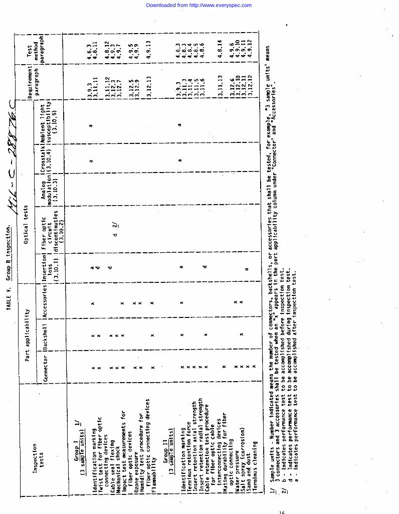
4.5.2.1 Group B inspection. Group B inspection shall consist of the tests specified in table Vin the order shOwn. Group inspection shall be performed on sample units of each style andselected from inspection lots which have passed group A inspection. Group B inspection samplesshall be representative of production.
4.5.2.1.1 Sampling plan. Every 18 months, connector, backshell, and accessory sample unitswhich have passed group inspection shall be selected in sufficient quantity to provide threesamples per applicable test group.
4.5.2.1.2 Sample unit preparation. Connectors shall be fully assembled into cable-connectorassemblies using the types of cable specified in DOD-C-85045. Connector tetminals shall beoptically finished with tennini properly seated within their inserts. For mated connectors, fullsealing capabiliw shall be provided as specified (see 3.1). Connectors shall be provided withbackshell, strain relief cable clamp, and attached to a 15-meter length of the specified cabletype, and shall be terminated in accordance with the manufacturer’s instructions.
4.5.2.1.3 Specimen. A specimen shall be a sample unit prepared in accordance with 4.5.2.1.2.
4.5.2.1.4 Failures. If one or more specimen or sample units fail to pass group B inspection,the sample shall be considered to have failed.
4.5.2.1.5 Disposition of sample units. Sample units which have been subjected to group Binspection shall not be dellvered on the contract or purchase order.
15
Downloaded from http://www.everyspec.com
J
u
._— ———-
.— -- ———— -—-——— ———— ———- ———- -——— —-
-——— ———— ———— —————————— --—— --———-
m e
-—-— ————— ————————— ———— ——-— ——-— —.
-———— —-——— —-——————— ————— —-—— —-—.
\NI
v
——————-——— ————-—-— -——— ———— -———— .
-v v m w m
-———— ————— —-——— —-——— —— —-— —-——— -,
x x xxx x x%
—-——— -———— ————— -———- ---——— —————
xx xxx x x x x
———.— —- ———— ———— ———— ———— —-—— -——— —
xx Xxx xxx’ Xx xxx x Xxxx
_—-— — ———— ———_ -_——- ———— ——-— -————
.__— ——— ——.
Downloaded from http://www.everyspec.com
MIL-C-28876C
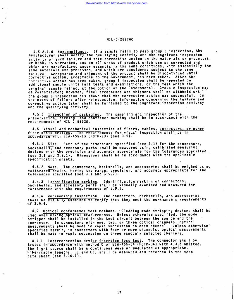
4.5.2.1.6 Noncompliance. If a sample fails to pass group B inspection, themanufacturer shall notity the qualifying activity and the cognizant inspectionactivity of such failure and take corrective action on the materials or processes,or both, as warranted, and on all units of product which can be corrected andwhich are manufactured under essentially the same conditions, with essentially thesame materials and processes, and which are considered subject to the samefailure. Acceptance and shipment of the product shall be discontinued untilcorrective action, acceptable to the Government, has been taken. After thecorrective action has been taken, group B inspection shall be repeated onadditional sample units (all tests and examinations, or the test which theoriginal sample failed, at the option of the Government). Group A inspection maybe reinstituted; however, final acceptance and shipment shall be withheld untilthe group B inspection has shown that the corrective action was successful. Inthe event of failure after reinspection, information concerning the failure andcorrective action taken shall be furnished to the cognizant inspection activityand the qualifying activity.
4.5.3 Inspection of packaging. The samplini
and inspection of thepreservatlon, packing, and container marking s all be in accordance with therequirements of MIL-C-55330.
4.6 Visual and mechanical inspection of fibers, cables, connectors, or otherfiber optic devices. The requirements for visual inspection shall be inaccordance with X-455-13 (FOTP-13) (see 3.9).
4.6.1 Size. Each of the dimensions specified (see 3.1) for the connectors,backshell~nd accessory parts shall be measured using calibrated measuringdevices with the precision and accuracy appropriate for the tolerances specified(see 3.1 and 3.9.1). Dimensions shall be in accordance with the applicablespecification sheets.
4.6.2 Mass. The connectors, backshells, and accessories shall be weighed usingcalibrate~ales, having the range, precision, and accuracy appropriate for thetolerances specified (see 3.1 and 3.9.2).
4.6.3 Identification marking. Identification marking on connectors,backshells, and accessory parts shall be visually examined and measured forconformance with the requirements of 3.9.3.
4.6.4 Workmanship inspection. The connectors, backshells, and accessoriesshall be visually examined to verjfy that they meet the workmanship requirements“of 3.9.4.
4.7 Optical conformance test methods. “Cladding mode stripping devices shall beused when maki ng optical measurements. Unless otherwise specified, the modestripper shall be installed in the test circuit between the source and theconnector. In connectors-with one, two, or three optical channels, opticalmeasurements shall be made in rapid succession on each channel. Unless otherwisespecified herein, in connectors with four or more channels, optical measurementsshall be made in rapid succession on three randomly selected channels.
4.7.1 Interconnection device insertion loss test. The connector shall betested in accordance with th c f EIA -- 34 (EOTP-34) with 4.3.6 omitted.The light source shall be ~eco~tinu~us wave or modulated as appropriate.Fiber/cable lengths, L and L2, shall be measured and recorded in the test
\data sheet (see 3.10.1 .
17
Downloaded from http://www.everyspec.com
MIL-C-28876C
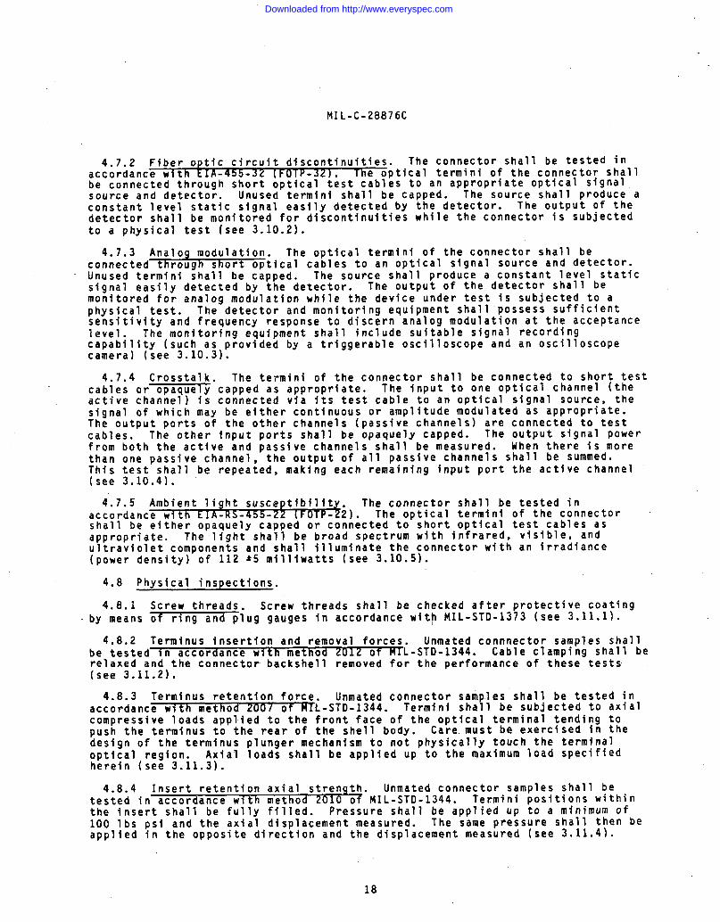
4.7.2 Fiber optfc circuit discontinuities. The connector shall be tested inaccordance with EIA-45b-3Z [FOTp 32) T he optical termini of the connector shallbe connected through short optic~l t~st cables to an appropriate optical signalsource and detector. Unused termini shall be capped. The source shall produce aconstant level static signal easily detected by the detector. The output of thedetector shall be monitored for discontinuities while the connector is subjectedto a physical test (see 3.10.2).
4.7.3 Analog modulation. The optical termini of the connector shall beconnected through short optical cables to an optical signal source and detector.Unused termini shall be capped. The source shall produce a constant level staticsignal easily detected by the detector. The output of the detector shall bemonitored for analog modulation while the device under test is subjected to aphysical test. The detector and monitoring equipment shall ”possess sufficientsensitivity and frequency response to discern analog modulation at the acceptancelevel. The monitoring equipment shall include suitable signal recordingcapability (such as provided by a triggerable oscilloscope and an oscilloscopecamera) (see 3.10.3).
4.7.4 Crosstalk. The termini of the connector shall be connected to short testcables or opaquely capped as appropr’iate. The input to one optical channel (theactive channel) is connected via its test cable to an optical signal source, thesignal of which may be either continuous or amplitude modulated as appropriate.The output ports of the other channels (passive channels) are connected to testcables. The other input ports shall be opaquely capped. The output signal powerfrom both the active and passive channels shall be measured. When there is morethan one passive channel, the output of all passive channels shall be summed.This test shall be repeated, making each remaining input port the active channel(see 3.10.4).
4.7.5 Ambient light susceptibility The connector shall be tested inaccordance with EIA-RS-455-Z2 The optical termini of the connectorshall be either opaquely capped or connected to short optical test cables asappropriate. The light shall be broad spectrum with infrared, visible, andultraviolet components and shall illuminate the connector with an irradiance(power density) of 112 ●5 milliwatts (see 3.1O.5).
4.8 Physical inspections.
4.8.1 Screw threads. Screw threads shall be checked after protective coating- by means of ring and plug gauges in accordance with MIL-STD-1373 (see 3.11.1).
4.8.2 Terminus insertion and removal forces. Unmated connector samples shallbe tested in accordance with method Zolz of MTL-STD-1344. Cable clamping shall berelaxed and the connector backshell removed for the performance of these tests(see 3.11.2).
4.8.3 Terminus retention force. Unmated connector samp.les’shall be tested inaccordance with method of flL-sTD-1344. Termini shall be subjected to axialcompressive loads applied to the front face of the optical terminal tending topush the terminus to the rear of the shell body. Care. must be exercised in thedesign of the terminus plunger mechanism to not physically touch the terminaloptical region. Axial loads shall be applied up to the maximum load specifiedherein (see 3.11.3).
4.8.4 Insert retention axial strength. Unmated connector samples shall betested in accordance with method 2010 of MIL-STD-1344. Termini positions withinthe insert shall be fully filled. Pressure shall be applied up to a minimum of100 Ibs psi and the axial displacement measured. The same pressure shall then beapplied in the opposite direction and the displacement measured (see 3.11.4).
18
Downloaded from http://www.everyspec.com

MIL-C-28876C
WALL MOUNTING
\
RECEPTACLE CONNECTCRSHOWN WITH STRAINRELIEF
/
RIGIDMOUNTING PANEL IAPPLIED LOAD
P
I
f
PLUG CONNECTORSHOWN WITH STRAINRELIEF
+\—___ ____ -—- 1
~~
----------- 1,
MOM ENT ARM 1
FIXTURE.SEE NOTE I
\/“
FIBER OPTIC CA8LEFIBER OPTIC CABLETO TEST EQUIPMENT TO TEST EQUIPMENT
NOTES:1. Moment arm fixture shall be of a convenient design.2. Oimension “H” is the smallest exterior dimension of connector.
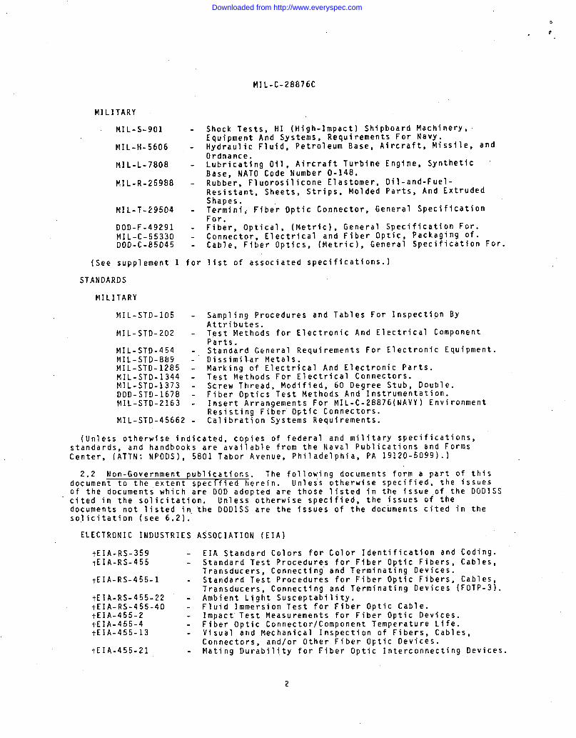
FIGURE 1. Test, external bending moment, fixture and setup connector, fiber optic.
19
Downloaded from http://www.everyspec.com

J
MIL-C-28876C
4.8.5 Insert retention radial strength. Unmated connector samples shall betested, w~ere specifl d ( 3 ) for radial strength as described herefn.Counterpart test devl~es ~~~ piug~ and receptacles shall be supplled by theconnector manufacturer which are capable of applying radial torque forces betweenthe insert and its shell body. Outermost termini positions or other means may beused for application of these torques, however, no damage shall occur to theinsert as a result of the test exposure. Torque loading shall be applied up tothe maximum specified (see 3.1) in each rotational direction (see 3.11.5).
4.8.6 :able retention test procedure for fiber optfc cable interconnectfn~devices. Rated connector samples snail b t t d In accordance wltn PUIP-b of~455. The axfal tensfle load shallebee~p~lied up to the load specified (see3.11.6) and shall be maintained for 10 minutes.
4.8.7 External bending moment. Cable-connector assemblies shall be tested inaccordance with he foil owing procedures. The cabled receptacle shall be mountedas fn normal service to a rigid panel. Before matfng the cabled plug to thereceptacle, a bending moment test arm shall be secured to the rear of the plugshell . The fixture shall be of any convenient design for application of the loadexcept it must not provide support for the connector shell in front of the engagedthreads (see figure 1). After mating the plug and receptacle, the bending momentload of 300 inch pounds as measured from the panel shall be applied. The load (P)shall be applied across the smallest exterior dimension (H) of the connector (seefigure 1). The load shall be applied at a rate of approximately 10 inch-poundsuntil the required load is applied. The maxfmum load shall be held for 1 minute(see 3.11.7).
4.8.8 Coupling torques. 14ateable connectors or accessories shall be tested forradial engagement and isengagement torques in accordance with method 2013 of141L-STD-1344 (see 3.11.8).
4.8.9 Fiber optic connector/component temperature life. 14ated cable-connectorassemblies shall be tested fn accordance with test condf~fon 3 and test time:o~;f;jon B of EIA-455-4 (FOTP-4). 14easurements shall be made after testing (see. . .
4.8.10 Maintenance agi Unmated connectors shall be tested in accordancewith method Z(JOZ of MIL-S The termini selected for insertion and removalshall be the same termfni to be used subsequently for optical testing. The forcerequired to insert and remove each terminus in and from the connector shall bemeasured during the first and final maintenance aging cycle (see 3.11.10).
4.8.11 Twist test for fiber optic connecting devfces. Mated cable-connectorassemblies shall be tested in accordance wit~ kIA-RS-~ -36 (FOTP-36). Theconnector-held fixture shall be rotated ●360 at a rate of one cycle per 5 secondsfor a total of 50 cycles. The cable assembles shall be stretched with minfmumtension of 11.0 pounds to.their maximum lengths and clamped at a distance of about100 times the cable diameter from the connector to the table top. Measurementsshall be made before and after testing (see 3.11.11).
4.8.12 Cable seal flexfn Unmated cable-connector assemblies, or each type tobe qualfffed shall be teste fn accordance with method 2017 of MIL-STD-1344 (see3.11.12).
4.8.13” 14atfng durability for fiber optic connectfn~. Connectors shall betested in accordance with EIA-455-21 [F7m-zl) Pive hundred complete (partseparating) cycles (mate and unmate) shall be ~ccomplished by hand at the rate of1 cycle per 15 seconds (see 3.11.13).
4.8.14 Backshell and accessory attachment. Connector backshells andaccessories shall be manually mated and unmated five times to their counterpartconnectors (see 3.11.14).
20
Downloaded from http://www.everyspec.com
MIL-C-28876C
4.9 Environmental tests.
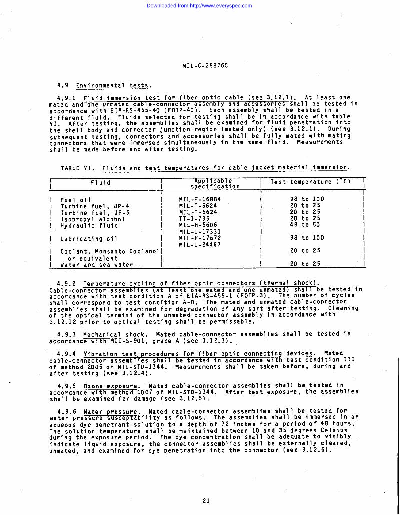
4.9.1 Fluid immersion test for fiber optic cable (see 3.12.1). At least onemated and one unmated cabl e-connector assembly and accessories Fhall be tested inaccordance with EIA-RS-455-40 (FOTp-40). Each assembly shall be tested in adifferent fluid. Fluids selected for testing shall be in accordance with table
After testing, the assemblies shall be examined for fluid penetration into~;; shell body and connector junction region (mated only) (see 3.12.1). Duringsubsequent testing, connectors and accessories shall be fully mated with matingconnectors that were immersed simultaneously in the same fluid. Measurementsshall be made before and after testing.
TABLE VI. Fluids and test temperatures for cable jacket material immersion.
-rFluid I I
IApplicable Test temperature (9C)
specification I
I Fuel oil I MIL-F-16884 I 98 to 100I Turbine fuel, JP-4I Turbine fuel, JP-5
I NIL-T-5624 20 to 25 IMIL-T-5624 ! 20 to 25 I
I Isopropyl alcohol\ Hydraulic fluid
TT-I-735 20 to 25 I/ MIL-H-5606 / 48 to 50 I
~ Lubricating oilMIL-L-17331
~ MIL-H-17672 / 98 to 100 /MIL-L-24467 I
I Coolant, Monsanto Coolanoll / 20 to 25 II or equivalent II Water and sea water } 20 to 25 I
4.9.2 Temperature cycling of fiber optic connectors (thermal shock).Cable-connector assembli ( least one mated and one unmated] be tested inaccordance with test con%~ti~~ A of EIA-RS-455-1 (FOTP-3). The ;u;ber of cyclesshall correspond to test condition A-O. The mated and unmated cable-connectorassemblies shall be examined for degradation of any sort after testing. Cleaningof the optical termini of the unmated connector assembly in accordance with3.12.12 prior to optical testing shall be permissible.
4.9.3 Mechanical shock. Mated cable-connector assemblies shall be tested inaccordance with MIL-S-90f, grade A (see 3.12.3).
4.9.4 Vibration test. procedures for fiber optic connecting devices. Matedcable-connector assembl ies shall be tested in accordance with test condition IIIof method 2005 of 141L-STO-1344. Measurements shall be taken before, during andafter testing (see 3.12.4).
.4.9.5 Ozone exposure. ‘Mated cable-connector assemblies shall be, tested in
accordance with th d 1007 of MIL-sTD-1344. After test exposure, the assembliesshall be examine%efo~ damage (see 3.12.5).
4.9.6 Uater pressure. Mated cable-connector assemblies shall be tested forwater pressure susceptibility as follows. The assemblies shall be immersed in anaqueous dye penetrant solution to a depth of 72 inches for a period of 48 hours.The solution temperature shall be maintained between 10 and 35 degrees Celsiusduring the exposure period. The dye concentration shall be adequate to visiblyindicate liquid exposure, the connector assemblies shall be externally cleaned,unmated, and examined for dye penetration into the connector (see 3.12.6).
21
Downloaded from http://www.everyspec.com
MIL-C-28876C
\
DUST COVER
r
CONNECTOR
/-
BACKSHELL(PLUG SHOWN) STRAIN RELIEF
\\
\
72.0CABLE OR
I I
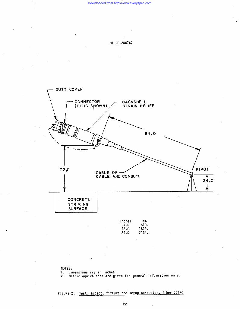
bE.E_l-Inches24.0 6fi.72.0 1829.84.0 2134.
NOTES:1. Dimensions are in inches.2. Metric equivalents are given for general information only.
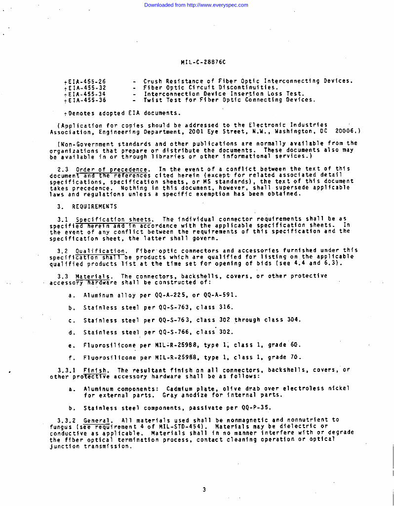
FIGURE 2. Test, impact, fixture and setup connector, fiber optic”
22
Downloaded from http://www.everyspec.com

MIL-C-28876C
4.9.7 Impact test measurements for ffber optic devices (see 3.12.7). Theunmated cab les assemb TY with backshell and Protective cover shall be tested inaccordance with EIA-45~-2 (FOTP-2 and figure ‘2). The cable assembly shall berepeatedly dropped observing the height sequence (highest drops first) and numberof drops specified. The cable assembly shall be extended its full length from thetest fixture. The plug or receptacle shall be dropped 8 times (light serviceclass) and rotated after each fall so that the connector strikes the impact pad ineight different radial positions. The test assemblies shall be examined fordamage, then mated. Terminus cleaning procedure of 3.12.12 may be employed afterexposure and prior to mating.
4.9.8 Crush resistance. Cable-connector assemblies shall be tested inaccordance with .- ~6 (FOTP-26) using 225 lbs as the test load (see 3.12.8).
4.9.9 Humidity test procedure for fiber optic connecting devices.Cable-connector assembli ( least one mated andin accordance with test ~~pea;I,
one unmated) shall be testedof EIA-RS-455 (FOTP-5). The s~bcycle shall be
included in the testing. Measurements shall be made before and after testing.
4.9.10 Salt spray (corrosion). Mated cable-connector assemblies shall betested in accordance with test condition C of method 1001 of MIL-STD-1344. Aftertest exposure, the assemblies shall be externally cleaned and examined underthree-power magnification for salt penetration into the connector junction areaand damage to external parts (see 3.12.10).
4.9.11 Sand and dust. Connectors mated and unmated, as applicable, shall besubjected to the dust Cfine sand) test of MIL-STD-202, method 110 (see 3.12.11).
4.9.12 Terminus cleaning. The optical face of terminus shall be cleanedaccording to the instructions supplied by the connector manufacturer. (Theterminus shall not be removed from its operational position within the connectorto facilitate cleaning (see 3.12.12).
4.9.13 Flammability. Flammability of connectors and accessories (at least 1mated and unmated) shall be tested in accordance with method 1012 ofMIL-STD-1344 with the flame applied for 60 seconds (see 3.12.13).
5. PACKAGING
5.1 Packaging requirements. The requirements ~or packaging shall be inaccordance with MIL-C-55330.
6. “NOTES
(This section contains information ’of a general or explanatory nature that maybe helpful, but is not mandatory.)
,6.1 Intended use. The fiber optic cables covered by this specification are
intended for use in the following applications as specified (see 3.1) where theirperformance characteristics are required:
a. Fixed plant. Used in systems in fixed locations includlng indoor,outdoor aerial, direct burial, duct and undersea applications.
b. Tactical. Concerned with use in nonvehicular and mobile militarizedsystems.
c. Space. Which .involves use in vehicles or systems deployed in outer space.
d. Avionics. Involving use in aircraft or missile systems.
23
Downloaded from http://www.everyspec.com
J
MIL-C-28876C
1’
e. Shipboard. Involving use in systems deployed in a mobile marineenvironment (on board or in tow).
f. Ground vehicle. Involving use in land vehicular systems.
9. Other specialized military specifications
6,1.1 Special considerations for application categories. The following list isintended to serve as a reminder in generating a detal 1 specification sheet. It isnot all inclusive; however, it highlights some of the special considerations.Important to each application are specific requirements as follows:
a. Fixed plant:
(1) Inside (plenum): Flame and toxicity, breakouti
(2) Aerial: Wide temperature range, solar radiation.
(3) Duct: Narrow temperature range, water immersion.
(4) Buried: Rodent protection, crush resistance.
(5) Submarine: High pressure tensile strength for recovery.
b. Tactical: Ruggedness, water freeze, zero bend radius, nuclear.
c. Space: Outgassing in vacuum (change in composition), low-levelradiation, extreme temperature range, nuclear - for military applications.
d. Avionics: High temperature, vibration and altitude.
e. Shipboard: Watertight or nonwatertight.
f. Vehicle, ground: Flammability and toxicity.
6.2 Acquisition requirements. Acquisition documents must specify the following:
a. Title, number, and date of the specification.
b. Issue of DODISS to be cited in the solicitation, and if required, thespecific issue of individual documents referenced (see 2.1.1).
c. Part number.
d, Quantity of connectors required.
e. Inclusion of terminating tools, if desired (see 3.8).
6.3 Qualification. Uith respect to products requiring qualification, awardswill be made only for products which are, at the time set for opening of bids,qualified for inclusion in qualified products list (QPL-28876) whether or not suchproducts have actually been so listed by that date. The attention of thecontractors is called to these requirements, and manufacturers are urged toarrange to have the products that they propose to offer to the Federal Governmenttested for qualification in order that they may be eligible to be awardedcontracts or purchase orders for the products covered by this specification. Theactivity responsible for the qualified products list is Space and Naval WarfareSystems Command, DOD Standardization Program and Documents Division, Washington,DC 20363; however, information pertaining to qualification of products may beobtained from Defense Electronics Supply Center, DESC-EQ, Dayton, OH 45444.
24
Downloaded from http://www.everyspec.com
MIL-C-28876C
6.3.1 Conformity to qualified sample. It is understood that connectorssupplied under he contract shall b id entical in every respect to thequalification sample tested and fou~d satisfactory, except for changes previouslyapproved by the Government. Any unapproved changes from the qualification sampleshall constitute cause for rejection.
6.3.2 Provisions governing qualification SD-6. Copies of “Provisions GoverningQualification SD-6” may be obtained upon appli cation to Commanding Officer, NavalPublications and Forms Center, 5801 Tabor Avenue, Philadelphia, PA 19120.
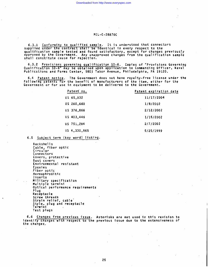
6.4 Patent notice. The Government does not have royalty-free license under thefollowing patents for the benefit of manufacturers of the item, either for theGovernment or for use in equipment to be delivered to the Government.
Patent no. Patent expiration date
US 65,032 11/17/2004
US 260,660 1/8/2002
US 376,866 2/12/2002
US 403,446 1/15/2002
US 751,204 2/7/2002
US 4,330,965 5/25/1999
6,5 Subject term (key word) listing.
BackshellsCable, fiber opticCircularConnectorsCovers, protectiveDust coversEnvironmental resistantEpoxiesFiber opticHermaphroditicInsertsMilitary specificationMultiple terminiOptical performance” requirementsPlugReceptacle
. Screw threadsStrain relief, cable-Style, plug and receptacleTerminiTest plugs
6.6 Changes from previous issue. Asterisks are not used in this revision toidentify changes with respect to the previous issue due to the extensiveness ofthe changes.
25
Downloaded from http://www.everyspec.com

MIL-C-28876C
APPENDIX
CONNECTOR INTERFACE DIMENSIONS
10. SCOPE
10.1 This at)gendix lists the connector interface dimensions and is a mandatorypart of the specification. The in’compliance.
20. APPLICABLE DOCUMENTS
This section is not appl
30. DRAWINGS
ormation contained herein is intended for -
cable to this appendix.
30.1 The connector interface dimension drawings (figures 3 through 10) arelisted as follows:
●
26
Downloaded from http://www.everyspec.com
NIL-C-28876C
APPENDIX
*.887 ~.005+
:546“x+--l I.230 MAX I l-,
I 4 I
[
MASTER[, I
POLAR IZING I IKEY +“L%7 h il I I ““ot”o’o
I
I /,))/111 I RDtA I II I-m
~SOCKET CONTACT /j
I-iDIA IREF
L
% I
U THREAD
m
-1
J-.&o GASKET THICKNESS
(GASKET CONFIGURATIONd
.887 REFOPTIONAL)
DETAIL A
!L —-x.SEE DETAIL
.010 MAX
J_
THREAD RELIEF
.195MAX
!--.176 MAX ‘
I Shell I U thread I isize ~ class 28 ~ d~a I d;a
I II I I I
i 11 ~ .~~O~.;P- i .502 (12.75) i .383 (9.73)I I .492 (12.50) ~ .373 (9.47)
1“-””11 I~ 13 i .875-.1P- i .626 (15.90) i .505 (12.83)
f .2L-D.S. f .616 (15.65) ~ .495 (12.57)I1 I I II 15 ~1.~f2~.~P- I .798 (20.27) I .683 (17.35)I .-. . I .788 (20.02) I .673 (17.09)
L idia ~
I
.365 (9.27) I.361 (9.17) i
I
.487 (12.37) I
.483 (12.27) I
.665 (16.89) I
.661 (16.79) II I I I I I
Inc&s
.004
.005.010.100.110.125.176.195.230.546.887
Iml,0.100.130.252.542.793.184.474.955.84
13.8722.53
.E.’
A
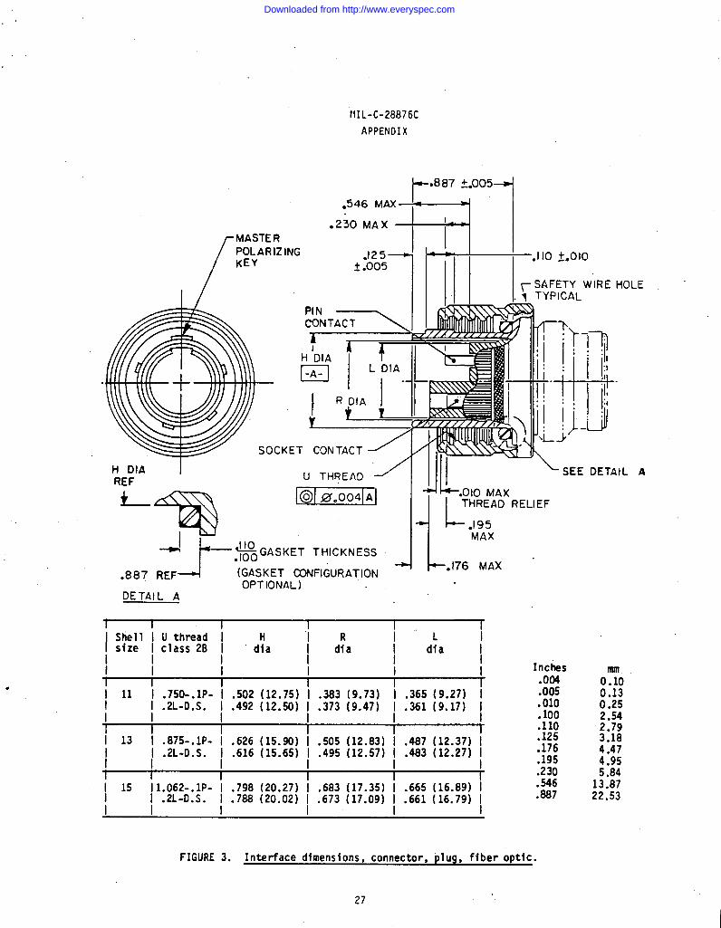
FIGURE 3. Interface dimensions, connector, plug, fiber optic.
27
Downloaded from http://www.everyspec.com

MIL-C-28876C
APPENDIX
NOTES :
::3.4.5,6.7.
8.
9.
Dimensions are in inches.Metric equivalents are given for general information only.Metric equivalents are in parentheses,Dimensions apply after plating.Mating key positions and dimensions are shown on figure 5.This design information establishes connector intermating criteria.Rear end connector design for attachment of nonrotatable strain reliefhardware and is shown on figure 8.Dimension includes terminus axial float; terminus will move back duringmating.See MIL-C-28876/6 through MIL-C-2887619 for appropriate plug outerconfiguration dimensions.
.
FIGURE 3. Interface dimensions, connector, plug, fiber optic - Continued.
28
Downloaded from http://www.everyspec.com
MIL-C-28876C
APPENDIX
~MASTER POLARIZING
/
KEYWAY
PIN CONTACT\
Q15 ‘tm
+
4!5° * 3° CH
~D,A r
n-A -
L DIA
jL
M!zBllX)20 MAX—
THREAD RELI
.325 MAX
T I I I rlShell I T thread I FIsize
I! class 2A 1
Idfa I d~a I
I1
I I I I
I 11 ~ .;~~.:P- 1.515 (13.08) 1.365 (9.27) [I 1.506 (12.85) 1.361 (9.17) II 1“-””1’ II I I
1. I 1
I 13 i .875-.1P- i.639 (16.23i’i.487 (12.37) iI .2L-D.S. ~.630 (16.00) ~.483 (12.27) I
i I 11
1 I1 I
II
i 15 p:2i.;P- i.all (20.60) io665 (16.89) !./ 1.80 (20.3) ~.661 (16.79) I
1“-””1 I* I
.
—
i
4.
L .600MIN FULLKEYWAY
J--1 -MAX.140 ‘+Qlo
_ .635f@5
Inches.004.005.010.U15.020.140.195.230.325.600.635.675.854
mm0.100.130.250.380.513.564.955.848.26
15.2416.1317.1421.69
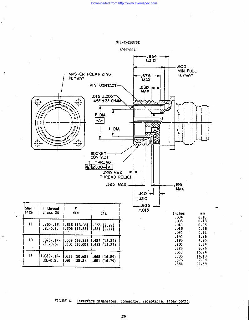
FIGURE 4. Interface dimensions, connector, receptacle, fiber optic.
29
Downloaded from http://www.everyspec.com
NIL-C-28876C
APPENDIX
NOTES :1. Dimensions are in inches.2. Metric equivalents are given for general information only.3. ,Metric equivalents are in parentheses.4. Dimensions apply after plating.5. Mating key positions and dimensions are shown on figure 5.6. This design information establishes connector intennating criteria.7. Rear end connector design for attachment of nonrotatable strain relief
hardware and is shown on figure 8.8. Oimension includes terminus axial float; terminus will move back during
mating.9. See MIL-C-28876/l throughMIL-C-28876/5 andMIL-C-28876/11 through
MIL-C-28876/14 for appropriate plug outer configuration dimensions.
.
FIGURE 4. Interface dimensions, connector, receptacle, fiber optic - Continued.
30
Downloaded from http://www.everyspec.com
MIL-C-28876C
APPENDIX
●
RECEPTACLE
a-c-
PLUG
MASTER POLARIZING~ ~*Qo2 .-. IP-0-
KEYWAY u II J!’-.131~+JO02 MASTER POLARIZING
Yp Old
H DIA
..= m ‘ ‘‘~,maml-’ \ .
&OIA TYP 4 KEYS
TYP 4 KEYWAYS W
1 I I rI Shel1 II size I
i id:a I d~a” I
I I I
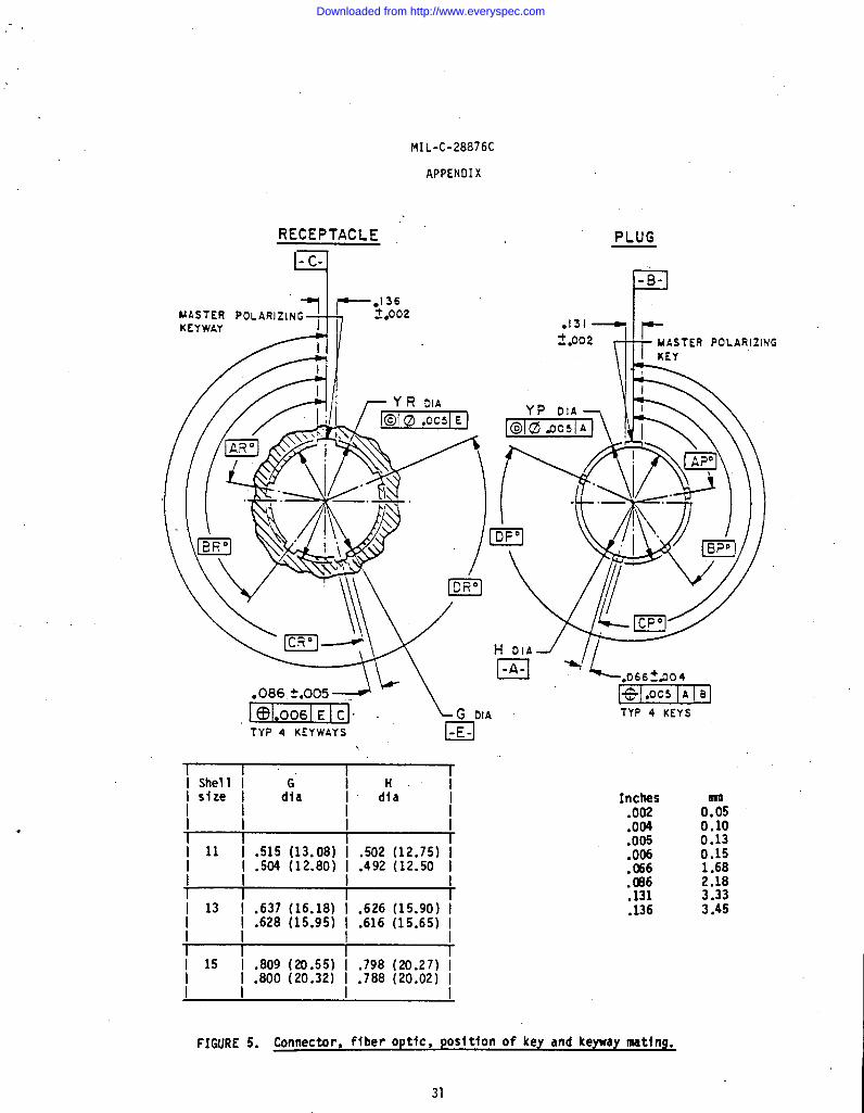
-I 11 I .515 (13.08) I .502 (12.75) II I .504 (12.80) I .492 (12.50 I
\ 13 I .637 (16.18) I .626 (15.90) I: .628 (15.95) ~ .616 (15.65) I
I I-i 15 I .809 (20.55) i .798 (20.27) I~ ~ .800 (20.32) ~ .788 (20.02) I
I, I
Inches.002.004.005.006. C6640;
.136
0:50.100.130.151.682.183.333.45
FIGURE 5. Connector, ffber optic, posftfon of key and keyuay mating.
31
Downloaded from http://www.everyspec.com
MIL-C-28876C
APPENDIX
.
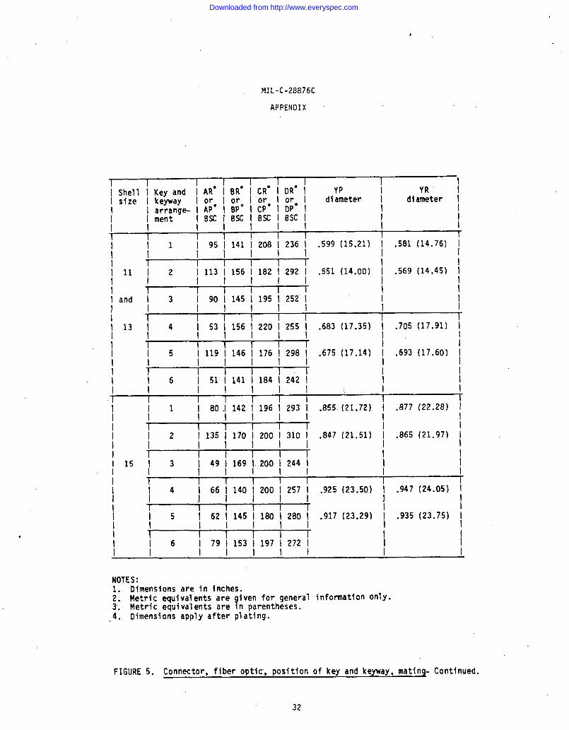
1 I I I I I II Shell ! Key and I AR* I BRO I CRO I DRO I YP~sizel keyway Iorlorlorlorl diameter
I arrange- I AP” I BPO I CP” 1 DP” II I ment IBSCIBSCIBKIBSC!
i il j 95 i 141 i 208 i 236 i .599 (15.21)
illi2 i 113 i 156 i 182 i292 i .551 (14.00)I I 11111
iandi3 i90i145i195i252iI !! 111
/~1314 I 53 \ 156 ~ 220 ~ 255 I .683 (17.35)
I ,I I 119 ~ 146 \ 176 \ 298 I .675 (17.14)I I 1 I
i! 1 I
16 151114111841242!I I 1! 111.
i il i 130.I142 ~ 196 ~ 293 [ .855(21.72)II ~
I 135 \ 170 ~ 200 ~ 310 I .847 (21.51)II ,115~3 149~169~200\244~I 1I -I I I I Ii i4 I 66 1.140 i 200 \ 257 i .925 (23.50)II +++--++i i5 I 62 i145 i 180 I 280 I .917 (23.29)
IYR i
diameter I
.5B1 (14.76) I
.569 (14.45) ~IIII
.7o5 (17.91) iII
,693 (17.60) IIIII
.877 (22.28) jI
.865 (21,97) IIII
.947 (24.05) I!
.935 (23.75) \II
i i6 i79i153i197i 2721 I Ii i iiill I I
NOTES:1. Dimensions are in inches.2. Metric equivalents are given for general information only.3. Metric equivalents are in parentheses..4. Dimensions apply after plating.
FIGURE 5. Connector, fiber optic”,position of key and keyway, mating- Continued.
32
Downloaded from http://www.everyspec.com

MIL-C-28876C
APPENDIX
●
RER
PIDIAMETER INTERNAL THREADS MINOR
DIAMETER
i i Deslgnatlon I Inches IISU I Inches mI i I .0100 0.254 I
I.8392 21.316
I II Shell 1 Thread I Pftch ~ Lead I
.0120 0.51 I .8490 21.565
.020 0.305 ~ .8590 21.819I size \ size I I .1 3. .8750I I II
22.225.8790 22.327
%42 1;:887 /I .8950 22.733[ 11~.75001 .1 ~.21 .7142 18.141 I 1.0025 25.464I I I .7240 18.3%) I 1.0145 25.768
.7340 18.644 1 1.CQ85 26.124T 13 .8750 .11 .21 .7500 19.050 I 1.0405 26.429
.7540 19.152 I 1.ti25 26.988I I I
~ 15 ~ 1.0625 I .1.7700 19.588 1 1.0665 27.~9
1.2~I I
.8292 21.062 I 1.0865 27.597
-1 I r~ ~ Internal thread 1imits of size I
II
i I I TI Shell I Minor diameter I Pitch diameter ~ Major diameter II size I I II I i II Limits I Toler- I Limits I Toler- I Lfmits I
1~ ~’ a“e ]~ + awe m
~ Min ~ Max I ~ Min ~ Max I1 I I I I I
I I I II 11 I .7042 I .7142 j .O1OO ~ .7240 ~ .7340 ~ .o1oo ~ .7540 ~ .7700 ~I I
,.
I I I I I I I r
I 13 I .8292 I .8392 [ .O1oo ~ .84W ~ .8590 ~ .o1oo ~ ●8790 j ●8950 ~I I I
I I I 1 I I rI 15 ~ 1.0025 ~ 1.0145 ~ .0120 ~ 1.0285 ~ 1.0405 ~ .0120 ~ 1.0665 ~ 1.0865 1I I
NOTES:1. Dimensions are in inches.21 ietric equivalents are given for general information only.3. Formulas for these values are given intable YII of MIL-STD-1373.4. For all other dimensions not shown above, refer to NIL-NO-1373.
FIGURE 6. Connector matinq threads (internal).
33
Downloaded from http://www.everyspec.com
MIL-C-28876C
APPENDIX
.
ER
PITCHDIAMETE
+M I’NOR
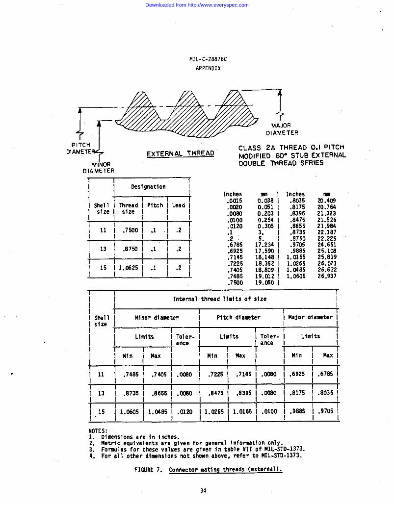
EXTERNAL THREADCLASS 2A THREAD 0.1 PITCHMOOIFIED 60° STUB EXTERNALDOUBLE THREAD SERIES
DIAMETER
1 I ri i Oestgnatlon ~I I Inches
.0015● 0020.0080.0100.0120.1.2 ~.6785.6925.7145.7225.7405.7485.7500
IISII I Inches0.038 I .80350.051 I .81750.203 I .83950.254 I .84750.305 I .86553. I .8735
.87501;:234 I .970517.590 I .988518.148 I 1.016518.352 I 1.026518.809 I 1.048519.012 I 1.060519.050 I
20%20.76421.32321.52621.98422.18722.22524.65125.10825.81926.07326.63226.937
1 I rI I Internal thread llmlts of size
I I/ I II shell I Minor diameter I Pitch diameter I Major diameter II size I I I II I II I Llmfts I Toler- I Limits 1 Toler- I Llmlts I1 I ante I I ante I1 ~ ~~ l-l--+
I MIn ; Max I I Min I Max ~/ I I I I I [ !
I Ij 11 \ .7485 ~ .7405 \ .0080 ~ .7225 I .7145 ; .Uo \ .6925 \ .6785 I
I I1 I I I I~ 13 \ ●8735 ~ .8655 j .~o ~ .8475 ~
I I I.8395 \ .0080 \ .8175 ~ .8035 I
I 11 I I I~ 15 ~ 1.0605 ~ 1.0485 ~ .0120 ~ 1.0265 ‘
I I I
I1.0165 I .0100 ~ .9885 ~ .9705 I
I I
;OTES:. Dimensions are in iriches.
2. Metric equivalents are given for general information only.3. Formulas for these values are given intable VII of MIL-STD-1373.4. For all other dimensions not shown above, refer to MIL-STO-1373.
FIGURE 7. Connector mating threads (external).
34
Downloaded from http://www.everyspec.com
MIL-C-28876C
APPENDIX
0.51
5.8913.94
DETAIL AFF DIA )
1
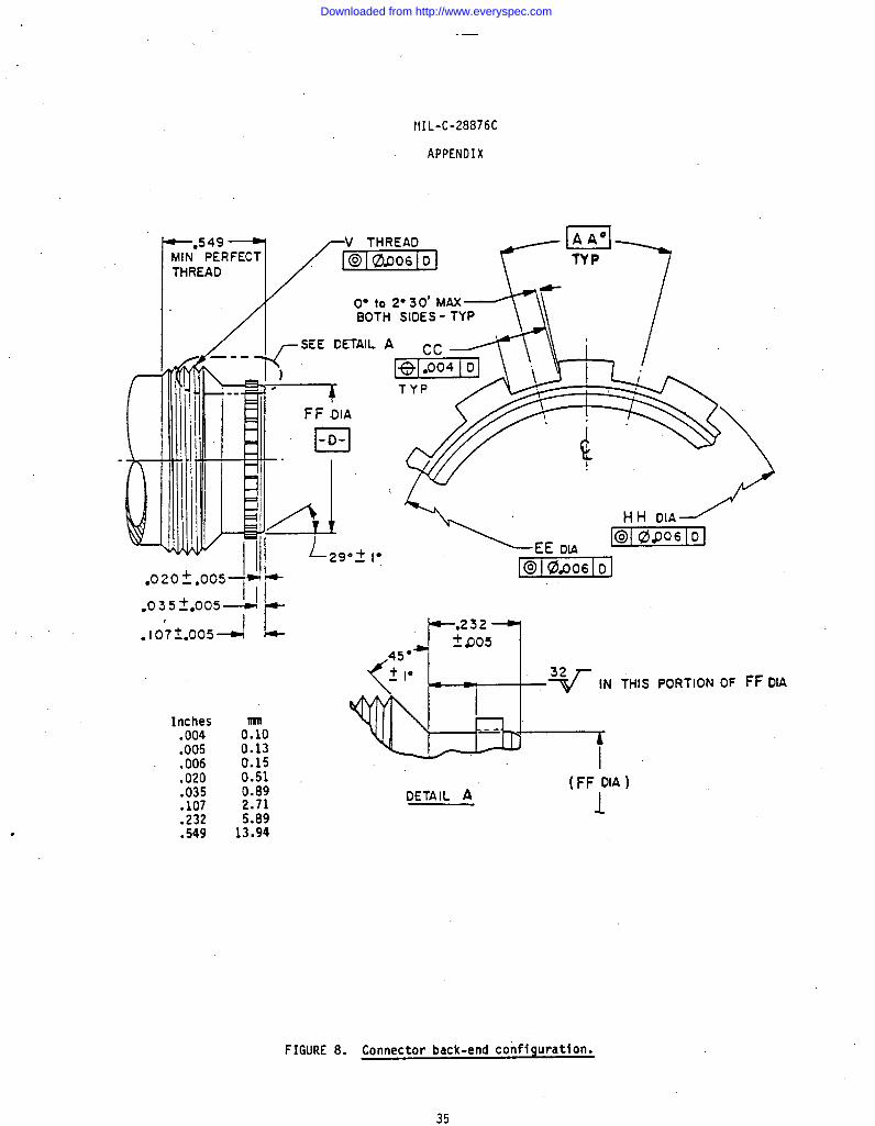
FIGURE 8. Connector back-end configuration.
35
Downloaded from http://www.everyspec.com

>
MIL-C-28876C
APPENDIX
t I I 1 I I I II Shell I AA I cc, I V thread I EE I FF I HHI size \ 8SC I I class 2A I diameter I diameter II I 1
diameter II I I i
II 11 I 20° I .0534 (1.356) I .750-20 I .547 (13.89) I .538 (1s.67) I .571 (14.50) III I .0484 (1.229) I UNEF I .541 (13.74) I .532 (13.51) I .565 (14.35) II II 1, I I I I
113’ ~20°1 .0634 (1.610) 1 .875-20 I .662 (16.81) I .653 (16.59) I .686 (17.42) II \ .0584 (1.483) I UNEF I .656 (16.66) I .647 (16.1$3)I .680 (17.27) II I I I t I I
II 15 I 18° I .0679 (1.725) I 1.000-20 \ .797 (20.24) I .788 (20.02) t .821 (20.85) II I I .0629 (1.598) I UNEF .791 (20.09) ! .782 (19.86) I .815 (20.70) II II I I 1 I
NOTES:1. Dimensions are in inches.2. Metric equivalents are given for general information only.3. Metric equivalents are in parentheses.4. Dimensions apply after plating.5. This design information establishes interface criteria for strain relief
assembly attachment in accordance with figure 9.
.
FIGURE 8. Connector backlend configuration - Continued,
36
Downloaded from http://www.everyspec.com
MIL-C-28876C
APPENDIX
K SPUNE KEY-TyP
-TY P
LF
1A)
Y45”
T--
/,.
7[.245 t.010
.172 $002 DIA HOLEX.0751.005 DEEP2 PLACES EQUALLYSPACEO AT 180” t2” AfJART
WIRE HOLE..
SEE DETAIL G
+ ‘&a--M.,READ/ L- .820~10 J
~ Ix””’”’”’oInches.002 0?5.004 0.10.005 0.13.006 0.15.010 0.25.060 1.52
. .050 1.27.075.088 :::.172 4.37.238 6.05.245 6.22.820 20.83
FIGURE 9.
“K’”<llfm-H-rv\m .’.-.’. ,
OETAJL G
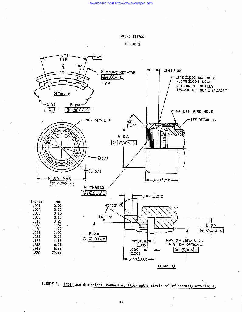
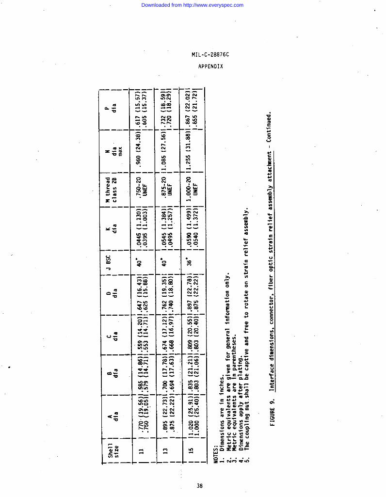
Interface dimensions, connector, fiber optic strain relief assembly attachment.
37
Downloaded from http://www.everyspec.com
.
MIL-C-28876C
APPENDIX
.
— --.-r-l%mm. .5s!-.-10-10-to. .— —-
t%*“N
.-.x0.Nml
.
. .S-$4--
g:00. .
.——-
. -.
00No00. .l+;
.——-
UI
I
Id
EwIA
38
Downloaded from http://www.everyspec.com
MIL-c-28876C
APPENDIX
.
M THREAD /..
-
1 I I I I
II Ill lE!lQ@il
s
.075
.090
.172
.245
0750.130.150.250.511.902.294.376.22
.290 7.3714.73
:6% 16.00
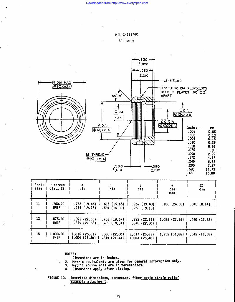
1 Shell I U thread I c iE i NI size I class2B I
i zz id~a I dia I dia
II dia I dia I
I / /
.766 (19 46) ~. 616 (15 65) ~“
max I I/ I I
I1111 .750-20 I .767 (19.48) I
I .754 (19:15) I :594 (15:09) I .753 (19.13) I.960 (24.38) I .340 (8.64) I
I I UNEF I II I I I “ I - -i i i
I 13, ~ .;jmi20 I .891 (22.63) I .731 (18.57) I .892 (22.66) I 1.085 (27.56) ~ .460 (11.68) II I .879 (.22.33)~ .709 (18.01) ~ .878 (22.30) II I I
II I I
I II 15 I 1.000-20 I 1.016 (25.81) I .866 (22.00) I 1.017 (25.83) I 1.255 (31.88) I .645 (16.38) II I UNEF I 1.004 (25.50) ~ .844 (21.44) ~ 1.003 (25.48) ~I I .1 / 1
NOTES:1. Dimensions are in inches.2. Metric equivalents are given for general information only.3. Metric equivalents are in parentheses.4. Dimensions apply after plating.
FIGURE 10. Interface dimensions, connector, fiberoptic strain reliefassembly attachment.
.
39
Downloaded from http://www.everyspec.com
MIL-C-28876C
CONCLUDING MATERIAL
Custodians:Army - CRNavy - ECAir Force - 85
Review activities:Army - MINavy - AS. MC. SHAir-Force-- 11, 17, 19, 80, 90, 99NASA - NADLA - ES -
Preparing activity:Navy - EC
Agent:OLA - ES
(Project 6060-0066)
User activities:Navy - OS, YDAir Force - 13, 14
40
Downloaded from http://www.everyspec.com
Related Documents