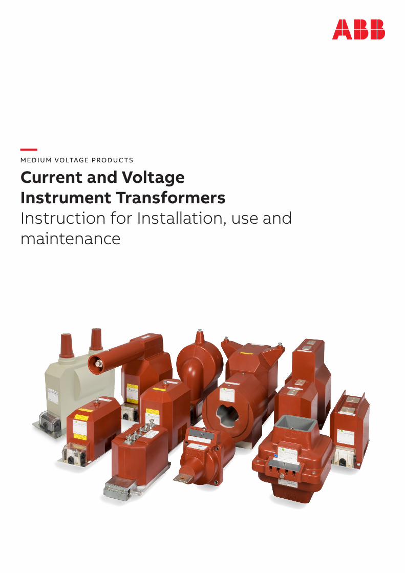
— MEDIUM VOLTAGE PRODUCTS Current and Voltage Instrument Transformers Instruction for Installation, use and maintenance

Welcome message from author
This document is posted to help you gain knowledge. Please leave a comment to let me know what you think about it! Share it to your friends and learn new things together.
Transcript
— MEDIUM VOLTAGE PRODUC TS
Current and Voltage Instrument TransformersInstruction for Installation, use and maintenance
2 CU R R E NT A N D VO LTAG E I N S TR U M E NT TR A N S FO R M E R SI NS TR U C TI O NS FO R I NS TA L L ATI O N , USE A N D M A I NTEN A N CE
— Scope of Contents
3 1. Service conditions3 2. Technical details4 3. Instructions for installation4 General informations4 Safety instructions 5 Mounting 5 Primary connection6 Secondary connection 7 Capacitive voltage indicator (divider) 7 Fuses 7 4. Instructions for use8 Routine test report 8 5. Instructions for maintenance8 6. Transport & Storage8 7. Disposal8 8. Handling with the transformer8 9. Normative references9 Appendix 1. Example of secondary terminal marking13 Appendix 2. Wiring diagrams16 Appendix 3. Damping ferroresonance for VT; VT Guard17 Appendix 4. Handling with transformer19 Appendix 5. Removing of cable grommet on a secondary terminal20 Appendix 6. Repair kit for metal coated VTs21 Appendix 7. Assemble the PT Sheet22 Appendix 8. Dimensional drawings
3
—Instructions for installation, use and maintenance for current and voltage transformers
1. Service conditions
The transformers should be mounted in dry indoor conditions where the ambient air is not signifi-cantly polluted by dust, smoke, corrosive gases, vapours or salt.
The transformers are designed for standard ambi-ent temperature between –5°C and +40°C. The al-titude for use should be lower than 1000 m above the sea level. The transformers may be used also in higher or lower ambient temperatures and higher altitudes when agreed between the manufacturer and purchaser.
2. Technical details
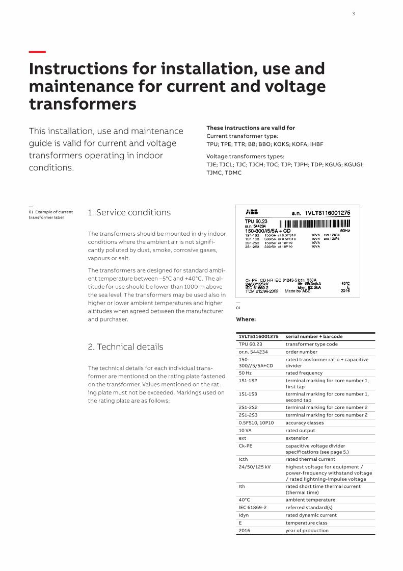
The technical details for each individual trans-former are mentioned on the rating plate fastened on the transformer. Values mentioned on the rat-ing plate must not be exceeded. Markings used on the rating plate are as follows:
Where:
1VLT5116001275 serial number + barcode
TPU 60.23 transformer type code
or.n. 544234 order number
150-300//5/5A+CD
rated transformer ratio + capacitive divider
50 Hz rated frequency
1S1-1S2 terminal marking for core number 1, first tap
1S1-1S3 terminal marking for core number 1, second tap
2S1-2S2 terminal marking for core number 2
2S1-2S3 terminal marking for core number 2
0.5FS10, 10P10 accuracy classes
10 VA rated output
ext extension
Ck-PE capacitive voltage divider specifications (see page 5.)
Icth rated thermal current
24/50/125 kV highest voltage for equipment / power-frequency withstand voltage / rated lightning-impulse voltage
Ith rated short time thermal current (thermal time)
40°C ambient temperature
IEC 61869-2 referred standard(s)
Idyn rated dynamic current
E temperature class
2016 year of production
—01
—01 Example of current transformer label
This installation, use and maintenance guide is valid for current and voltage transformers operating in indoor conditions.
These instructions are valid for Current transformer type: TPU; TPE; TTR; BB; BBO; KOKS; KOFA; IHBF
Voltage transformers types: TJE; TJCL; TJC; TJCH; TDC; TJP; TJPH; TDP; KGUG; KGUGI; TJMC, TDMC
4 CU R R E NT A N D VO LTAG E I N S TR U M E NT TR A N S FO R M E R SI NS TR U C TI O NS FO R I NS TA L L ATI O N , USE A N D M A I NTEN A N CE
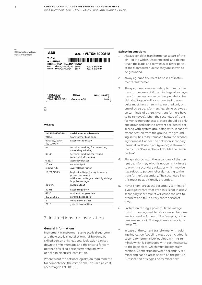
Where:
1VLT5216000812 serial number + barcodeTJC 4 transformer type code6000√3//100/ √3/100/3 V
rated voltage ratio
a-n terminal marking for measuring secondary winding
da-dn terminal marking for residual (open-delta) winding
0.5; 3P accuracy classes10 VA rated output1.9xUn/8h overvoltage factor
12/28/75 kV highest voltage for equipment / power-frequencywithstand voltage / rated lightning-impulse voltage
400 VA rated output
50 Hz rated frequency40°C ambient temperatureIEC 61869-3 referred standardE temperature class2016 year of production
3. Instructions for installation
General informationsInstrument transformer is an electrical equipment and the electrical installation shall be done by skilled person only. National legislation can set down the minimum age and the criteria for com-petence of skilled persons working on, with, or near an electrical installation.
Where is not the national legislation requirements for competence, the criteria shall be used at least according to EN 50110-1.
Safety instructions1. Always consider transformer as a part of the
cir cuit to which it is connected, and do not touch the leads and terminals or other parts of the transformer unless they are known to be grounded.
2. Always ground the metallic bases of instru-ment transformer.
3. Always ground one secondary terminal of the transformer, except if the windings of voltage transformer are connected to open delta. Re-sidual voltage windings connected to open delta must have dn terminal earthed only on one of three transformers (earthing screws at dn terminals of others two transformers have to be removed). When the secondary of trans-former is interconnected, there should be only one grounded point to prevent accidental par-alleling with system grounding wire. In case of disconnection from the ground, the ground-ing screw has to be removed from the second-ary terminal. Connection between secondary terminal and base plate (ground) is shown on the picture “Crossection of double line termi-nal box“
4. Always short-circuit the secondary of the cur-rent transformer, which is not currently in use to prevent secondary voltages which may be hazardous to personnel or damaging to the transformer’s secondary. The secondary like this must be additionally grounded.
5. Never short-circuit the secondary terminal of a voltage transformer even this is not in use. A secondary short-circuit will cause the unit to overheat and fail in a very short period of time.
6. Protection of single pole insulated voltage transformers against feroresonance phenom-ena is stated in Appendix 3. – Damping of the ferroresonance in Voltage transformers type range TJx.
7. In case of the current transformer with volt-age indication (coupling electrode included) is secondary terminal box equiped with PE ter-minal, which is connected with earthing screw to the base plate, which must be generally earthed. Connection between secondary ter-minal and base plate is shown on the picture “Crossection of single line terminal box“
—02 Example of voltage transformer label
—02
5
Attention: Terminal PE must be always earthed, this is hold generally, even if the base plate is re-moved. In case of disassembling the base plate, producer is not warranting the earthing. Cou-pling electrode terminals Ck and PE are always delivered interconnected. Remove this connec-tion before installation of indication system. Leave the connection if Ck-PE terminals are not in use.
8. All current and voltage transformers are, for safety reasons, shipped with earthed second-ary windings. Earthing of the terminals are shown in Appendix 1. Before putting into op-eration always check whether it corresponds to the earthing scheme involved in the appli-cation and remove earthing screws accord-ingly (simple examples of network connection are in Appendix 2 ).
Attention: Manufacturer is not responsible for damage, loss and injuries caused by wrong con-nection of transformers.
MountingFollowing informations are general and some de-tails can differentiate according to type and vari-ants of transformers. It is necessary to combine it with other technical and marketing specifications like catalogues, dimensional drawings and rating plate for specific transformer type.
The mounting position of the indoor transformer can be freely chosen. The transformer is fixed us-ing the mounting base with four screws M10 and washers. Fastening must be done on a smooth surface. There is a M8 screw for earthing the trans-former on the base plate.
Primary connectionPrimary terminals of the current transformer are made of copper and they are silver or tin plated. There are M12 (CT) and M10 (VT) screws used for fastening of primary conductor to the terminal. For primary reconnectable transformers the ratio can be reconnected by changing position of the links fixed by M8 screws without removing already fitted primary conductors.
Screw Max. torque [Nm] Min. torque [Nm]M5 3.5 2.8M6 4 3M8 20 16M10 20 16M12 70 56
Tab. 1. Maximum allowed torques for screw connections of current transformers
Maximum allowed torque for screw connection of voltage transformer is 20 Nm.
Maximum allowed cantilever strength is: Voltage transformers 2000 N. Current transformers 5000 N.
Primary connectors of metal coated transformers (TJMC, TDMC) should be cleaned by pressured air to eliminate all undesired impurities created from unpacking and manipulation. An alcohol can be used in case of any additional pollution caused by manipulation after unpacking.
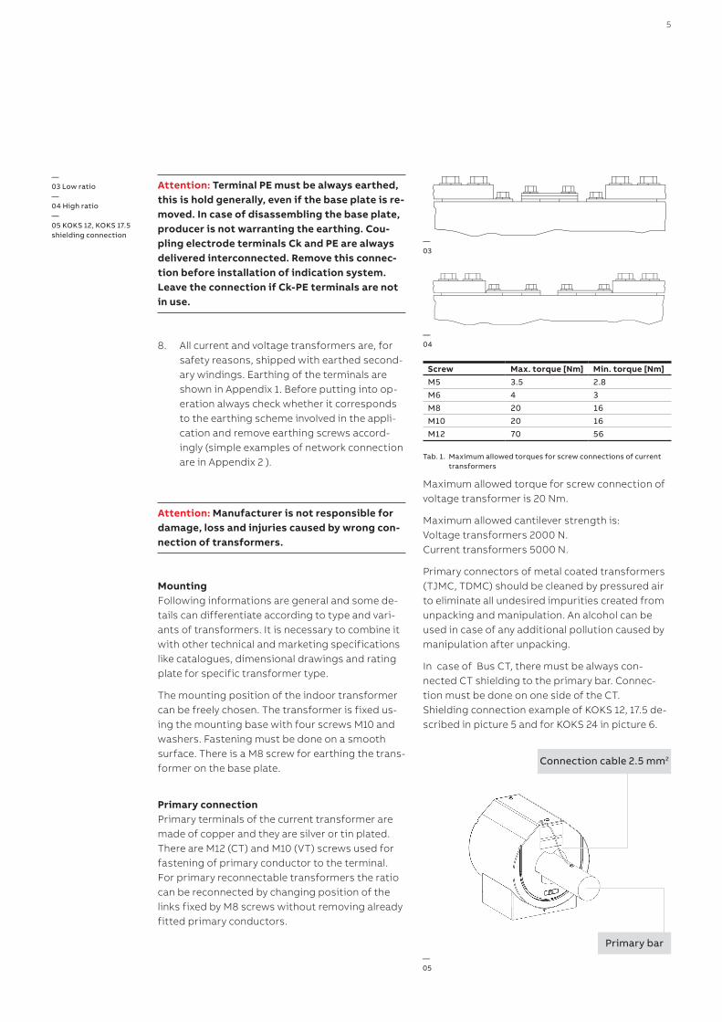
In case of Bus CT, there must be always con-nected CT shielding to the primary bar. Connec-tion must be done on one side of the CT. Shielding connection example of KOKS 12, 17.5 de-scribed in picture 5 and for KOKS 24 in picture 6.
—03 Low ratio—04 High ratio—05 KOKS 12, KOKS 17.5 shielding connection
—03
—04
—05
Connection cable 2.5 mm2
Primary bar
6 CU R R E NT A N D VO LTAG E I N S TR U M E NT TR A N S FO R M E R SI NS TR U C TI O NS FO R I NS TA L L ATI O N , USE A N D M A I NTEN A N CE
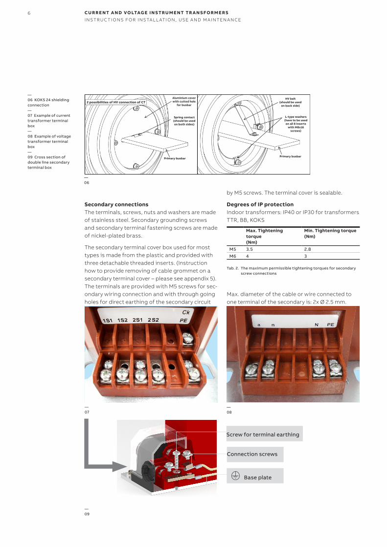
Secondary connectionsThe terminals, screws, nuts and washers are made of stainless steel. Secondary grounding screws and secondary terminal fastening screws are made of nickel-plated brass.
The secondary terminal cover box used for most types is made from the plastic and provided with three detachable threaded inserts. (Instruction how to provide removing of cable grommet on a secondary terminal cover – please see appendix 5). The terminals are provided with M5 screws for sec-ondary wiring connection and with through going holes for direct earthing of the secondary circuit
by M5 screws. The terminal cover is sealable.
Degrees of IP protectionIndoor transformers: IP40 or IP30 for transformers TTR, BB, KOKS
Max. Tightening torque (Nm)
Min. Tightening torque (Nm)
M5 3.5 2.8M6 4 3
Tab. 2. The maximum permissible tightening torques for secondary screw connections
Max. diameter of the cable or wire connected to one terminal of the secondary is: 2x Ø 2.5 mm.
—07
—09
—08
Connection screws
Screw for terminal earthing
Base plate
—06 KOKS 24 shielding connection —07 Example of current transformer terminal box—08 Example of voltage transformer terminal box—09 Cross section of double line secondary terminal box
—06
2 possibilities of HV connection of CTAluminium cover with cutted hole
for busbar
Spring contact (should be used on both sides)
Primary busbarPrimary busbar
HV belt (should be used
on back side)
L-type washers (have to be used on all 8 inserts
with M8x16 screws)
7
For terminal marking see Appendix 1.
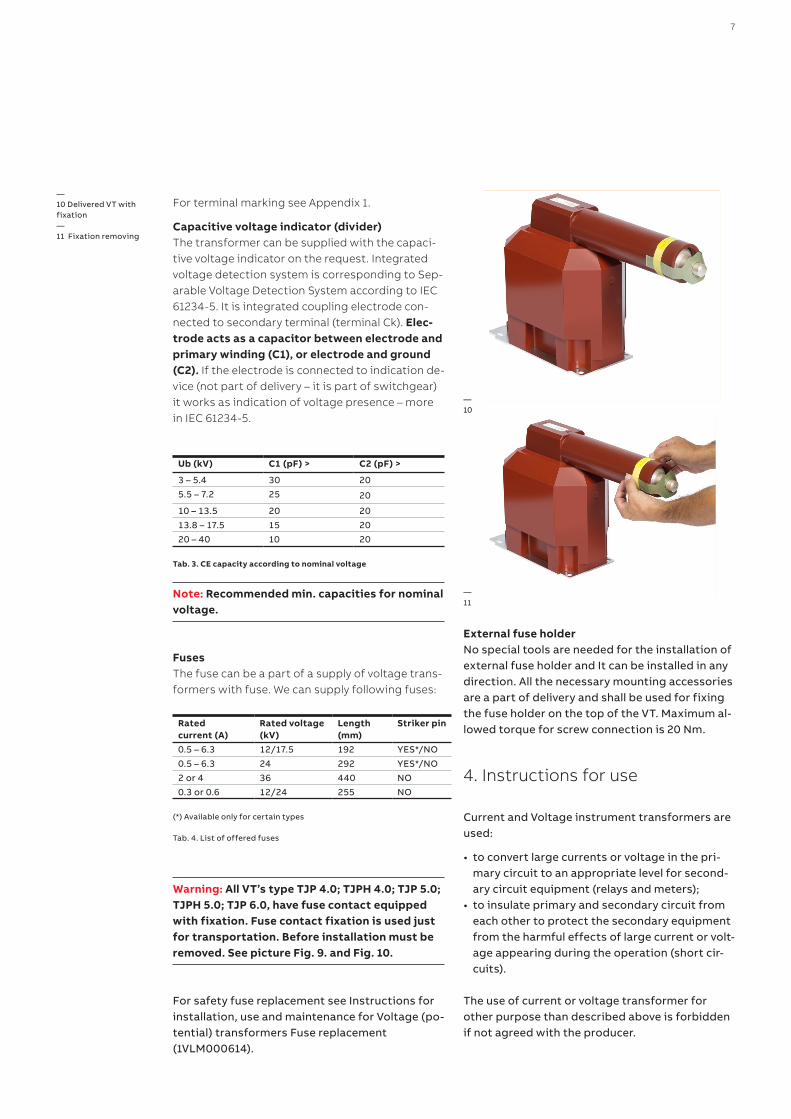
Capacitive voltage indicator (divider)The transformer can be supplied with the capaci-tive voltage indicator on the request. Integrated voltage detection system is corresponding to Sep-arable Voltage Detection System according to IEC 61234-5. It is integrated coupling electrode con-nected to secondary terminal (terminal Ck). Elec-trode acts as a capacitor between electrode and primary winding (C1), or electrode and ground (C2). If the electrode is connected to indication de-vice (not part of delivery – it is part of switchgear) it works as indication of voltage presence – more in IEC 61234-5.
Ub (kV) C1 (pF) > C2 (pF) >
3 – 5.4 30 205.5 – 7.2 25 20
10 – 13.5 20 2013.8 – 17.5 15 2020 – 40 10 20
Tab. 3. CE capacity according to nominal voltage
Note: Recommended min. capacities for nominal voltage.
Fuses The fuse can be a part of a supply of voltage trans-formers with fuse. We can supply following fuses:
Rated current (A)
Rated voltage (kV)
Length (mm)
Striker pin
0.5 – 6.3 12/17.5 192 YES*/NO 0.5 – 6.3 24 292 YES*/NO 2 or 4 36 440 NO 0.3 or 0.6 12/24 255 NO
(*) Available only for certain types
Tab. 4. List of offered fuses
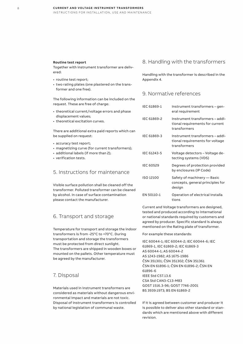
Warning: All VT’s type TJP 4.0; TJPH 4.0; TJP 5.0; TJPH 5.0; TJP 6.0, have fuse contact equipped with fixation. Fuse contact fixation is used just for transportation. Before installation must be removed. See picture Fig. 9. and Fig. 10.
For safety fuse replacement see Instructions for installation, use and maintenance for Voltage (po-tential) transformers Fuse replacement (1VLM000614).
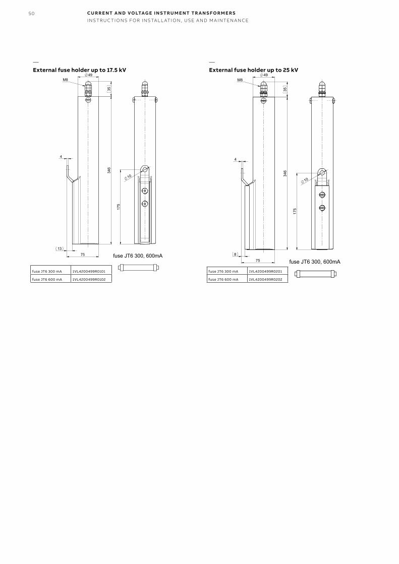
External fuse holder No special tools are needed for the installation of external fuse holder and It can be installed in any direction. All the necessary mounting accessories are a part of delivery and shall be used for fixing the fuse holder on the top of the VT. Maximum al-lowed torque for screw connection is 20 Nm.
4. Instructions for use
Current and Voltage instrument transformers are used:
• to convert large currents or voltage in the pri-mary circuit to an appropriate level for second-ary circuit equipment (relays and meters);
• to insulate primary and secondary circuit from each other to protect the secondary equipment from the harmful effects of large current or volt-age appearing during the operation (short cir-cuits).
The use of current or voltage transformer for other purpose than described above is forbidden if not agreed with the producer.
—10 Delivered VT with fixation—11 Fixation removing
—10
—11
8 CU R R E NT A N D VO LTAG E I N S TR U M E NT TR A N S FO R M E R SI NS TR U C TI O NS FO R I NS TA L L ATI O N , USE A N D M A I NTEN A N CE
Routine test reportTogether with instrument transformer are deliv-ered:
• routine test report;• two rating plates (one plastered on the trans-
former and one free).
The following information can be included on the request. These are free of charge:
• theoretical current/voltage errors and phase displacement values;
• theoretical excitation curves.
There are additional extra paid reports which can be supplied on request:
• accuracy test report;• magnetizing curve (for current transformers);• additional labels (if more than 2);• verification tests.
5. Instructions for maintenance
Visible surface pollution shall be cleaned off the transformer. Polluted transformer can be cleaned by alcohol. In case of surface contamination please contact the manufacturer.
6. Transport and storage
Temperature for transport and storage the indoor transformers is from -25°C to +70°C. During transportation and storage the transformers must be protected from direct sunlight. The transformers are shipped in wooden boxes or mounted on the pallets. Other temperature must be agreed by the manufacturer.
7. Disposal
Materials used in instrument transformers are considered as materials without dangerous envi-ronmental impact and materials are not toxic. Disposal of instrument transformers is controlled by national legislation of communal waste.
8. Handling with the transformers
Handling with the transformer is described in the Appendix 4.
9. Normative references
IEC 61869-1 Instrument transformers – gen-eral requirement
IEC 61869-2 Instrument transformers – addi-tional requirements for current transformers
IEC 61869-3 Instrument transformers – addi-tional requirements for voltage transformers
IEC 61243-5 Voltage detectors – Voltage de-tecting systems (VDS)
IEC 60529 Degrees of protection provided by enclosures (IP Code)
ISO 12100 Safety of machinery — Basic concepts, general principles for design
EN 50110-1 Operation of electrical installa tions
Current and Voltage transformers are designed, tested and produced according to international or national standards required by customers and agreed by producer. Specific standard is always mentioned on the Rating plate of transformer.
For example these standards:
IEC 60044-1; IEC 60044-2; IEC 60044-6; IEC 61869-1, IEC 61869-2; IEC 61869-3 AS 60044-1; AS 60044-2 AS 1243-1982; AS 1675-1986 ČSN 351301; ČSN 351302; ČSN 351361 ČSN EN 61896-1; ČSN EN 61896-2; ČSN EN 61896-6 IEEE Std C57.13.6 CSA Std CAN3-C13-M83 GOST 1516.3-96; GOST 7746-2001 BS 3939:1973; BS EN 61869-2
If it is agreed between customer and producer it is possible to deliver also other standard or stan-dards which are mentioned above with different revision.
9
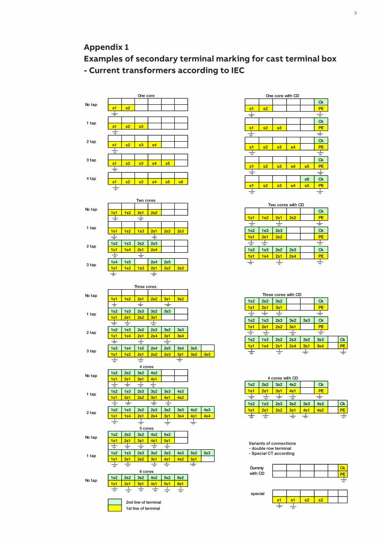
Appendix 1Examples of secondary terminal marking for cast terminal box - Current transformers according to IEC
Ck
s1 s2 s1 s2 PE
Ck
s1 s2 s3 s1 s2 s3 PE
Ck
s1 s2 s3 s4 s1 s2 s3 s4 PE
Ck
s1 s2 s3 s4 s5 s1 s2 s3 s4 s5 PE
s6 Ck
s1 s2 s3 s4 s5 s6 s1 s2 s3 s4 s5 PE
Ck
1s1 1s2 2s1 2s2 1s1 1s2 2s1 2s2 PE
1s2 1s3 2s3 Ck
1s1 1s2 1s3 2s1 2s2 2s3 1s1 2s1 2s2 PE
1s2 1s3 2s2 2s3 1s2 1s3 2s2 2s3 Ck
1s1 1s4 2s1 2s4 1s1 1s4 2s1 2s4 PE
1s4 1s5 2s4 2s5
1s1 1s2 1s3 2s1 2s2 2s3
1s2 2s2 3s2 Ck
1s1 1s2 2s1 2s2 3s1 3s2 1s1 2s1 3s1 PE
1s2 1s3 2s3 3s2 3s3 1s2 1s3 2s3 3s2 3s3 Ck
1s1 2s1 2s2 3s1 1s1 2s1 2s2 3s1 PE
1s2 1s3 2s2 2s3 3s2 3s3 1s2 1s3 2s2 2s3 3s2 3s3 Ck
1s1 1s4 2s1 2s4 3s1 3s4 1s1 1s4 2s1 2s4 3s1 3s4 PE
1s3 1s4 1s5 2s4 2s5 3s4 3s5
1s1 1s2 2s1 2s2 2s3 3s1 3s2 3s3
1s2 2s2 3s2 4s2 1s2 2s2 3s2 4s2 Ck
1s1 2s1 3s1 4s1 1s1 2s1 3s1 4s1 PE
1s2 1s3 2s3 3s2 3s3 4s3 1s2 1s3 2s3 3s2 3s3 4s3 Ck
1s1 2s1 2s2 3s1 4s1 4s2 1s1 2s1 2s2 3s1 4s1 4s2 PE
1s2 1s3 2s2 2s3 3s2 3s3 4s2 4s3
1s1 1s4 2s1 2s4 3s1 3s4 4s1 4s4
1s2 2s2 3s2 4s2 5s2
1s1 2s1 3s1 4s1 5s1
1s2 1s3 2s3 3s2 3s3 4s3 5s2 5s3 Ck
1s1 2s1 2s2 3s1 4s1 4s2 5s1 PE
1s2 2s2 3s2 4s2 5s2 6s2
1s1 2s1 3s1 4s1 5s1 6s1 s1 s1 s2 s2
2nd line of terminal
1st line of terminal
No tap
1 tap
No tap
2 tap
3 tap
No tap
1 tap
2 tap
Dummy with CD
6 cores
special
No tap
1 tap
2 tap
4 tap
3 tap
1 tap
2 tap
3 tap
No tap
No tap
1 tap
Three cores Three cores with CD
4 cores 4 cores with CD
5 cores
One core One core with CD
Two cores Two cores with CD
Variants of connections - double row terminal - Special CT according
Ck
s1 s2 s1 s2 PE
Ck
s1 s2 s3 s1 s2 s3 PE
Ck
s1 s2 s3 s4 s1 s2 s3 s4 PE
Ck
s1 s2 s3 s4 s5 s1 s2 s3 s4 s5 PE
s6 Ck
s1 s2 s3 s4 s5 s6 s1 s2 s3 s4 s5 PE
Ck
1s1 1s2 2s1 2s2 1s1 1s2 2s1 2s2 PE
1s2 1s3 2s3 Ck
1s1 1s2 1s3 2s1 2s2 2s3 1s1 2s1 2s2 PE
1s2 1s3 2s2 2s3 1s2 1s3 2s2 2s3 Ck
1s1 1s4 2s1 2s4 1s1 1s4 2s1 2s4 PE
1s4 1s5 2s4 2s5
1s1 1s2 1s3 2s1 2s2 2s3
1s2 2s2 3s2 Ck
1s1 1s2 2s1 2s2 3s1 3s2 1s1 2s1 3s1 PE
1s2 1s3 2s3 3s2 3s3 1s2 1s3 2s3 3s2 3s3 Ck
1s1 2s1 2s2 3s1 1s1 2s1 2s2 3s1 PE
1s2 1s3 2s2 2s3 3s2 3s3 1s2 1s3 2s2 2s3 3s2 3s3 Ck
1s1 1s4 2s1 2s4 3s1 3s4 1s1 1s4 2s1 2s4 3s1 3s4 PE
1s3 1s4 1s5 2s4 2s5 3s4 3s5
1s1 1s2 2s1 2s2 2s3 3s1 3s2 3s3
1s2 2s2 3s2 4s2 1s2 2s2 3s2 4s2 Ck
1s1 2s1 3s1 4s1 1s1 2s1 3s1 4s1 PE
1s2 1s3 2s3 3s2 3s3 4s3 1s2 1s3 2s3 3s2 3s3 4s3 Ck
1s1 2s1 2s2 3s1 4s1 4s2 1s1 2s1 2s2 3s1 4s1 4s2 PE
1s2 1s3 2s2 2s3 3s2 3s3 4s2 4s3
1s1 1s4 2s1 2s4 3s1 3s4 4s1 4s4
1s2 2s2 3s2 4s2 5s2
1s1 2s1 3s1 4s1 5s1
1s2 1s3 2s3 3s2 3s3 4s3 5s2 5s3 Ck
1s1 2s1 2s2 3s1 4s1 4s2 5s1 PE
1s2 2s2 3s2 4s2 5s2 6s2
1s1 2s1 3s1 4s1 5s1 6s1 s1 s1 s2 s2
2nd line of terminal
1st line of terminal
No tap
1 tap
No tap
2 tap
3 tap
No tap
1 tap
2 tap
Dummy with CD
6 cores
special
No tap
1 tap
2 tap
4 tap
3 tap
1 tap
2 tap
3 tap
No tap
No tap
1 tap
Three cores Three cores with CD
4 cores 4 cores with CD
5 cores
One core One core with CD
Two cores Two cores with CD
Variants of connections - double row terminal - Special CT according
10 CU R R E NT A N D VO LTAG E I N S TR U M E NT TR A N S FO R M E R SI NS TR U C TI O NS FO R I NS TA L L ATI O N , USE A N D M A I NTEN A N CE
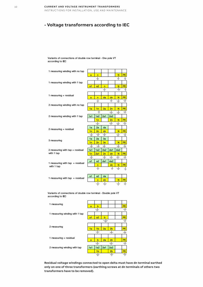
- Voltage transformers according to IEC
a n N PE
a1 a2 n N PE
a n da dn N PE
1a 1n 2a 2n N PE
1a1 1a2 2a1 2a2
1n 2n N PE
1a 2a da
1n 2n dn N PE
1a 2a 3a
1n 2n 3n N PE
1a1 1a2 2a2 da1 da2
1n 2a1 2n dn N PE
a1 a2 da1 da2
n dn N PE
a1 a2 da
n dn N PE
a b PE
a1 a2 b PE
1a 1b 2a 2b PE
a b da dn PE
1a1 1a2 2a1 2a2
1b 2b PE
1 measuring winding with 1 tap
2 measuring
1 measuring + residual
2 measuring winding with tap
1 measuring winding with no tap
1 measuring winding with 1 tap
1 measuring + residual
2 measuring winding with no tap
2 measuring winding with 1 tap
2 measuring + residual
3 measuring
2 measuring with tap + residual with 1 tap
1 measuring with tap + residual with 1 tap
1 measuring with tap + residual
1 measuring
Variants of connections of double row terminal - One pole VT according to IEC
Variants of connections of double row terminal - Double pole VT according to IEC
Residual voltage windings connected to open delta must have dn terminal earthed only on one of three transformers (earthing screws at dn terminals of others two transformers have to be removed).
11
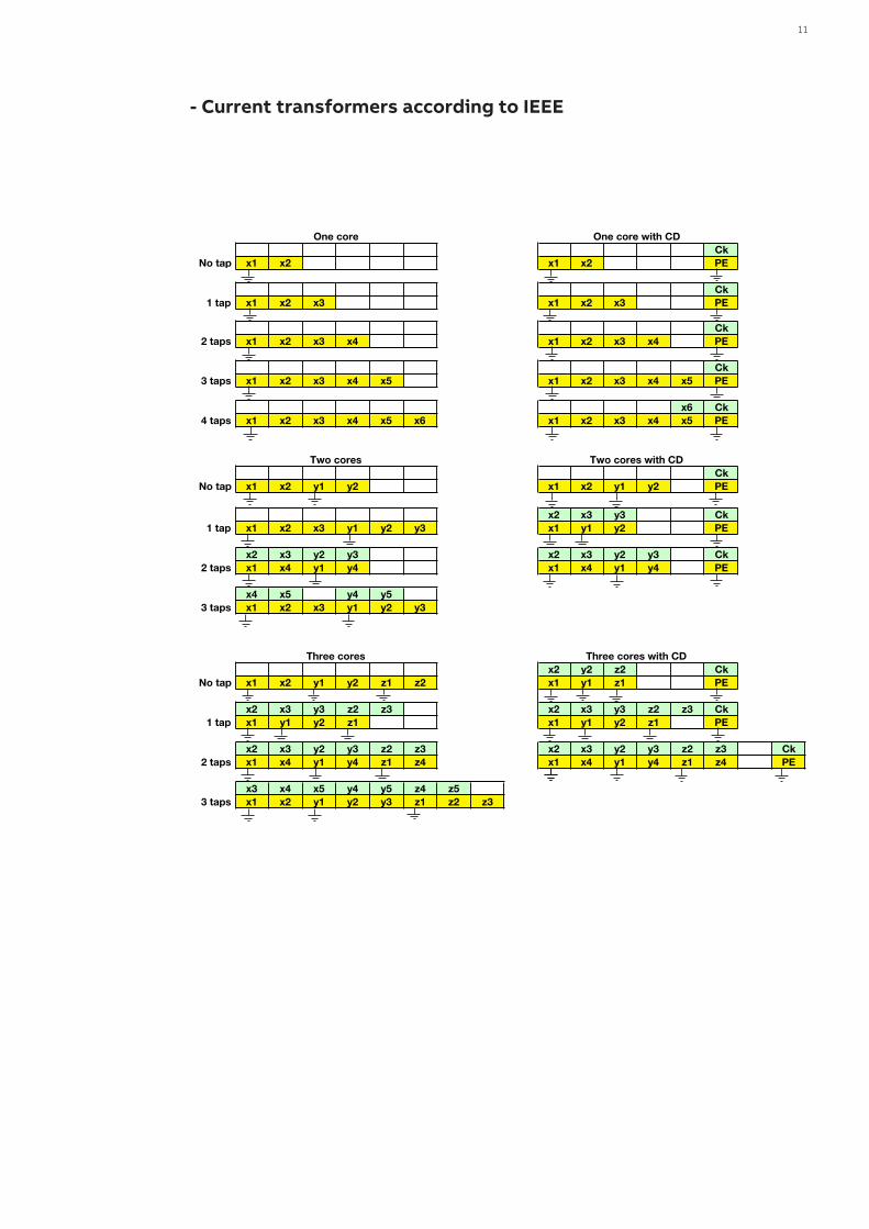
- Current transformers according to IEEE
CkNo tap x1 x2 x1 x2 PE
Ck1 tap x1 x2 x3 x1 x2 x3 PE
Ck2 taps x1 x2 x3 x4 x1 x2 x3 x4 PE
Ck3 taps x1 x2 x3 x4 x5 x1 x2 x3 x4 x5 PE
x6 Ck4 taps x1 x2 x3 x4 x5 x6 x1 x2 x3 x4 x5 PE
CkNo tap x1 x2 y1 y2 x1 x2 y1 y2 PE
x2 x3 y3 Ck1 tap x1 x2 x3 y1 y2 y3 x1 y1 y2 PE
x2 x3 y2 y3 x2 x3 y2 y3 Ck2 taps x1 x4 y1 y4 x1 x4 y1 y4 PE
x4 x5 y4 y53 taps x1 x2 x3 y1 y2 y3
x2 y2 z2 CkNo tap x1 x2 y1 y2 z1 z2 x1 y1 z1 PE
x2 x3 y3 z2 z3 x2 x3 y3 z2 z3 Ck1 tap x1 y1 y2 z1 x1 y1 y2 z1 PE
x2 x3 y2 y3 z2 z3 x2 x3 y2 y3 z2 z3 Ck2 taps x1 x4 y1 y4 z1 z4 x1 x4 y1 y4 z1 z4 PE
x3 x4 x5 y4 y5 z4 z53 taps x1 x2 y1 y2 y3 z1 z2 z3
Three cores Three cores with CD
One core One core with CD
Two cores Two cores with CD
x1 x2 H2 PE
x1 x2 x3 H2 PE
x1 x2 y1 y2 H2 PE
x1 x2 y1 y2x3 y3 H2 PE
x1 y1 z1x2 y2 z3 H2 PE
2 measuring winding with no tap
2 measuring winding with 1 tap
3 measuring
Variants of connections of double row terminal
1 measuring winding with no tap
1 measuring winding with 1 tap
12 CU R R E NT A N D VO LTAG E I N S TR U M E NT TR A N S FO R M E R SI NS TR U C TI O NS FO R I NS TA L L ATI O N , USE A N D M A I NTEN A N CE
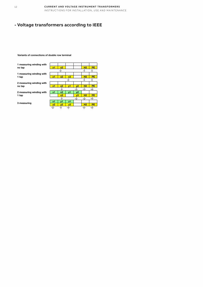
- Voltage transformers according to IEEE
CkNo tap x1 x2 x1 x2 PE
Ck1 tap x1 x2 x3 x1 x2 x3 PE
Ck2 taps x1 x2 x3 x4 x1 x2 x3 x4 PE
Ck3 taps x1 x2 x3 x4 x5 x1 x2 x3 x4 x5 PE
x6 Ck4 taps x1 x2 x3 x4 x5 x6 x1 x2 x3 x4 x5 PE
CkNo tap x1 x2 y1 y2 x1 x2 y1 y2 PE
x2 x3 y3 Ck1 tap x1 x2 x3 y1 y2 y3 x1 y1 y2 PE
x2 x3 y2 y3 x2 x3 y2 y3 Ck2 taps x1 x4 y1 y4 x1 x4 y1 y4 PE
x4 x5 y4 y53 taps x1 x2 x3 y1 y2 y3
x2 y2 z2 CkNo tap x1 x2 y1 y2 z1 z2 x1 y1 z1 PE
x2 x3 y3 z2 z3 x2 x3 y3 z2 z3 Ck1 tap x1 y1 y2 z1 x1 y1 y2 z1 PE
x2 x3 y2 y3 z2 z3 x2 x3 y2 y3 z2 z3 Ck2 taps x1 x4 y1 y4 z1 z4 x1 x4 y1 y4 z1 z4 PE
x3 x4 x5 y4 y5 z4 z53 taps x1 x2 y1 y2 y3 z1 z2 z3
Three cores Three cores with CD
One core One core with CD
Two cores Two cores with CD
x1 x2 H2 PE
x1 x2 x3 H2 PE
x1 x2 y1 y2 H2 PE
x1 x2 y1 y2x3 y3 H2 PE
x1 y1 z1x2 y2 z3 H2 PE
2 measuring winding with no tap
2 measuring winding with 1 tap
3 measuring
Variants of connections of double row terminal
1 measuring winding with no tap
1 measuring winding with 1 tap
13
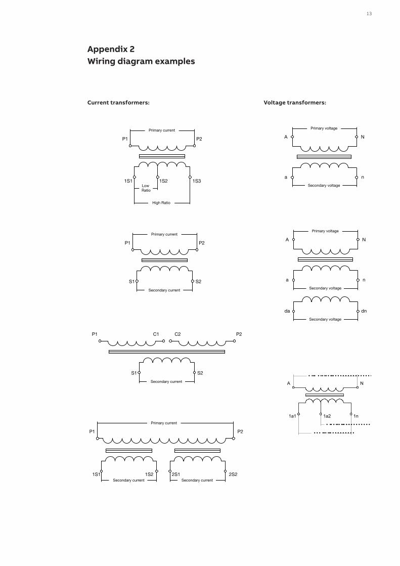
Appendix 2Wiring diagram examples
Current transformers: Voltage transformers:
Primary current
Secondary current
P1 P2
S1 S2
Primary current
High Ratio
Low Ratio
P1 P2
1S1 1S2 1S3
Primary current
P1 P2
Secondary current1S1 1S2
Secondary current2S1 2S2
P1 C1 C2 P2
Secondary current
S1 S2
Primary voltage
Secondary voltage
A N
a n
Primary voltage
Secondary voltage
A N
a n
Secondary voltage
da dn
• • • ••• ••• • • • • • • • • •
• •• • ••• ••• • • • • • • • • • •
• ••• • •• •• • ••• • • • • • • • • • • • • • • • • •
1n1a1 1a2
A N
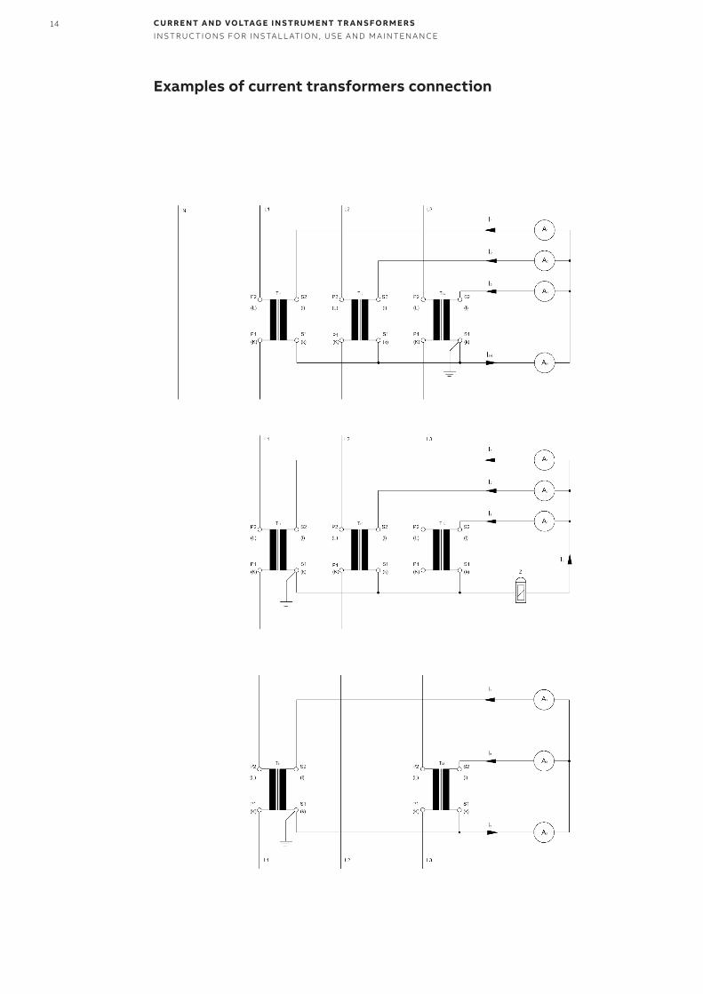
14 CU R R E NT A N D VO LTAG E I N S TR U M E NT TR A N S FO R M E R SI NS TR U C TI O NS FO R I NS TA L L ATI O N , USE A N D M A I NTEN A N CE
Examples of current transformers connection
15
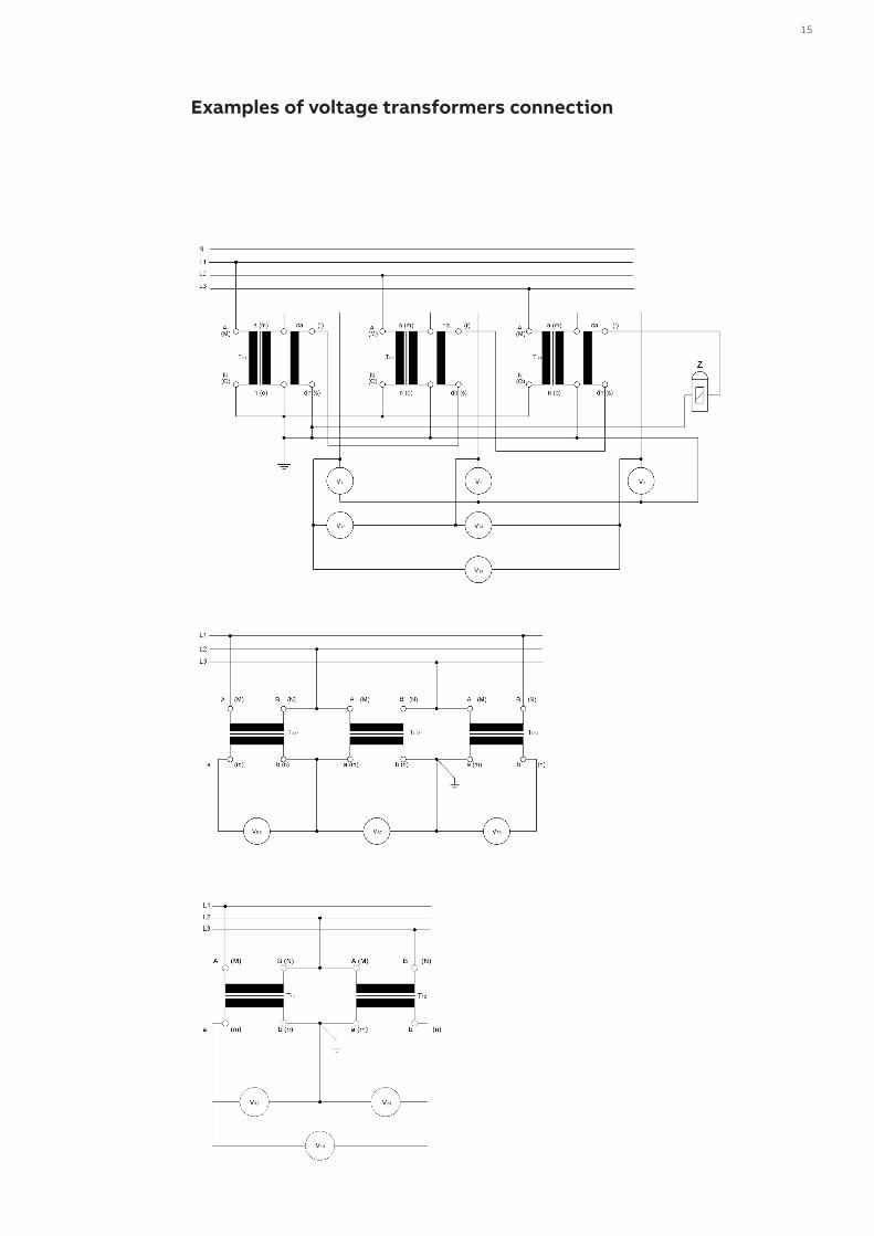
Examples of voltage transformers connection
16 CU R R E NT A N D VO LTAG E I N S TR U M E NT TR A N S FO R M E R SI NS TR U C TI O NS FO R I NS TA L L ATI O N , USE A N D M A I NTEN A N CE
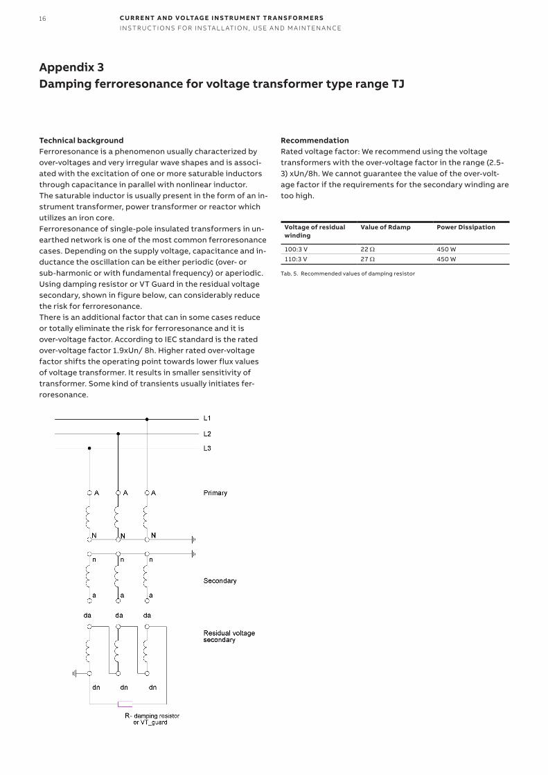
Appendix 3Damping ferroresonance for voltage transformer type range TJ
Technical backgroundFerroresonance is a phenomenon usually characterized by over-voltages and very irregular wave shapes and is associ-ated with the excitation of one or more saturable inductors through capacitance in parallel with nonlinear inductor. The saturable inductor is usually present in the form of an in-strument transformer, power transformer or reactor which utilizes an iron core. Ferroresonance of single-pole insulated transformers in un-earthed network is one of the most common ferroresonance cases. Depending on the supply voltage, capacitance and in-ductance the oscillation can be either periodic (over- or sub-harmonic or with fundamental frequency) or aperiodic. Using damping resistor or VT Guard in the residual voltage secondary, shown in figure below, can considerably reduce the risk for ferroresonance. There is an additional factor that can in some cases reduce or totally eliminate the risk for ferroresonance and it is over-voltage factor. According to IEC standard is the rated over-voltage factor 1.9xUn/ 8h. Higher rated over-voltage factor shifts the operating point towards lower flux values of voltage transformer. It results in smaller sensitivity of transformer. Some kind of transients usually initiates fer-roresonance.
RecommendationRated voltage factor: We recommend using the voltage transformers with the over-voltage factor in the range (2.5-3) xUn/8h. We cannot guarantee the value of the over-volt-age factor if the requirements for the secondary winding are too high.
Voltage of residual winding
Value of Rdamp Power Dissipation
100:3 V 22 Ω 450 W110:3 V 27 Ω 450 W
Tab. 5. Recommended values of damping resistor

17
There are few possibilities of handling:
1) Manual handling Transformers can be handled by hands in case the weight of the transformer is not higher than 25 kg. Always use glows during the manual handling. For grasp of the transformers always use handling grip (see the picture), or the base of the trans-former.
Note. This system is recommended for metal coated instrument transformers TJMC or TDMC. Types TJP, TDP, never handle by gripping the fuse holder – risk of break.
Transformers heavier than 25 kg can be handled by hands in case the transformer is equipped with baseplate. In this case the transformer must be carried by at least two persons using the base-plate. It is necessary to follow all safety instruc-tions during the manipulation.
2) Handling by beltsFor safety reasons transformers can be handled by hanging on belts when it is possible. Then the handling can be done by hanging of the trans-former on the crane.
Note. This system is recommended for types: TTR, TSR, BB(O), KOKS. Hanging systems for those types are visualized on pictures.
Safety warning! Lifting capacity of the belts and the crane has to be at least 200 kg. Always make sure that the belts hold safely on the crane and on the transformer.
3) Handling by the self-locking hooks It is possible to handle transformers by self-lock-ing hooks hanging on the crane, if the trans-former is equipped with handling grips. When the transformer has no handling grips, is it possible to grip the hooks under the base of the trans-former.
Note. This system is recommended for types: TPU, TPE, TJC, TJCL, TJCH, TJP, TJPH, TDP, TDC, KGUG, KGUGI. This handling system is visualized on the pictures.
Safety warning! Lifting capacity of the hooks and the crane has to be 200 kg at least. Always make sure that the hooks hold safely on the crane and on the transformer.
Appendix 4Handling with transformers
—11
—12
—13
—11 Manual handling—12 Transformer hanging on belts—13 Self locking hooks at-tached on the handling grips
18 CU R R E NT A N D VO LTAG E I N S TR U M E NT TR A N S FO R M E R SI NS TR U C TI O NS FO R I NS TA L L ATI O N , USE A N D M A I NTEN A N CE
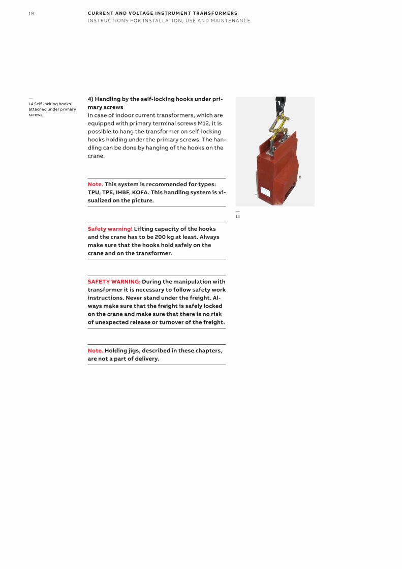
4) Handling by the self-locking hooks under pri-mary screws In case of indoor current transformers, which are equipped with primary terminal screws M12, it is possible to hang the transformer on self-locking hooks holding under the primary screws. The han-dling can be done by hanging of the hooks on the crane.
Note. This system is recommended for types: TPU, TPE, IHBF, KOFA. This handling system is vi-sualized on the picture.
Safety warning! Lifting capacity of the hooks and the crane has to be 200 kg at least. Always make sure that the hooks hold safely on the crane and on the transformer.
SAFETY WARNING: During the manipulation with transformer it is necessary to follow safety work instructions. Never stand under the freight. Al-ways make sure that the freight is safely locked on the crane and make sure that there is no risk of unexpected release or turnover of the freight.
Note. Holding jigs, described in these chapters, are not a part of delivery.
—14 Self-locking hooks attached under primary screws
—14

19
1) Step drill procedureIn case of use of a step drill, it is necessary to dis-mount a secondary terminal cover to prevent a damage of a transformer body. Maximal drill bit size is 20 mm.
A drilled plastic part shall be fully fixed to avoid any injuries. The pictures are for illustration pur-pose only.
It is recommended to clear the edges of all new holes immediately after drilling these holes. For these purposes, a rasper or a knife can be used. Cleaned secondary terminal cover can be mounted back to a body of transformer.
2) Screwdriver procedureIt is recommended to use a screwdriver to punc-ture a hole in a secondary terminal cover.
A screwdriver shall be placed to a weakened place close to a pre-perforated ring. Two dimensions of hole can be punctured.
1/ an inner diameter
2/ an outer diameter
If necessary, a plastic mallet can be used. The plastic mallet shall be used with ease.
It is recommended to clear the edges of all new holes immediately after puncturing these holes. For these purposes, a rasper or a knife can be used.
Note: Whole procedure must be realized with all caution, to avoid damage of a secondary termi-nal.
Appendix 5Removing of cable grommet on a secondary terminal cover
20 CU R R E NT A N D VO LTAG E I N S TR U M E NT TR A N S FO R M E R SI NS TR U C TI O NS FO R I NS TA L L ATI O N , USE A N D M A I NTEN A N CE
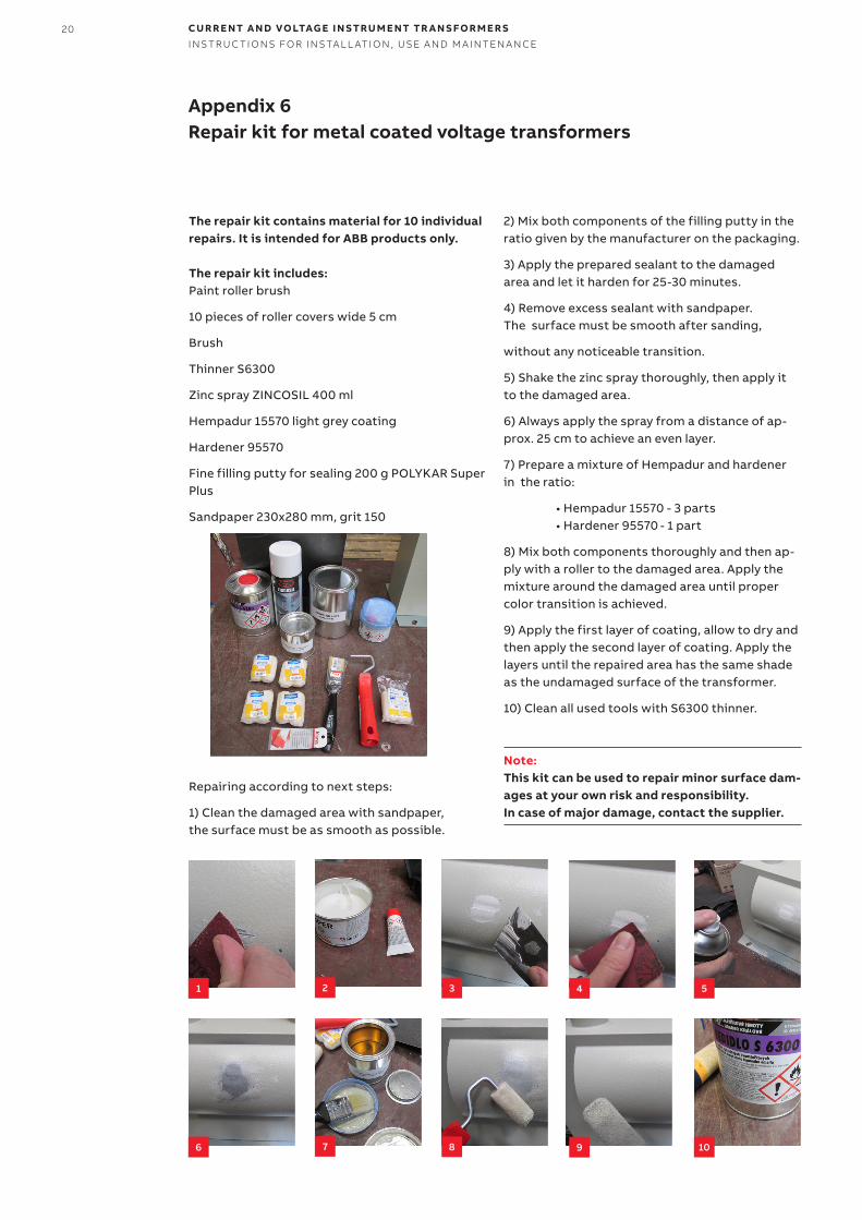
The repair kit contains material for 10 individual repairs. It is intended for ABB products only.
The repair kit includes:Paint roller brush
10 pieces of roller covers wide 5 cm
Brush
Thinner S6300
Zinc spray ZINCOSIL 400 ml
Hempadur 15570 light grey coating
Hardener 95570
Fine filling putty for sealing 200 g POLYKAR Super Plus
Sandpaper 230x280 mm, grit 150
Repairing according to next steps:
1) Clean the damaged area with sandpaper, the surface must be as smooth as possible.
2) Mix both components of the filling putty in the ratio given by the manufacturer on the packaging.
3) Apply the prepared sealant to the damaged area and let it harden for 25-30 minutes.
4) Remove excess sealant with sandpaper. The surface must be smooth after sanding,
without any noticeable transition.
5) Shake the zinc spray thoroughly, then apply it to the damaged area.
6) Always apply the spray from a distance of ap-prox. 25 cm to achieve an even layer.
7) Prepare a mixture of Hempadur and hardener in the ratio:
• Hempadur 15570 - 3 parts • Hardener 95570 - 1 part
8) Mix both components thoroughly and then ap-ply with a roller to the damaged area. Apply the mixture around the damaged area until proper color transition is achieved.
9) Apply the first layer of coating, allow to dry and then apply the second layer of coating. Apply the layers until the repaired area has the same shade as the undamaged surface of the transformer.
10) Clean all used tools with S6300 thinner.
Note: This kit can be used to repair minor surface dam-ages at your own risk and responsibility. In case of major damage, contact the supplier.
Appendix 6Repair kit for metal coated voltage transformers
1 2 3 4 5
6 7 8 9 10
21
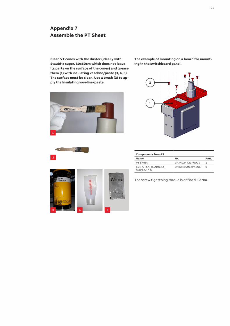
Clean VT cones with the duster (ideally with Staubfix super, 80x50cm which does not leave its parts on the surface of the cones) and grease them (1) with insulating vaseline/paste (3, 4, 5). The surface must be clean. Use a brush (2) to ap-ply the insulating vaseline/paste.
The example of mounting on a board for mount-ing in the switchboard panel.
Components from 2R... Name Nr. Amt.PT Sheet 2RJA024422P0001 1SCR-CTSK_ISO10642_M8X20-10.9
9ABA450064P4206 6
The screw tightening torque is defined 12 Nm.
Appendix 7Assemble the PT Sheet
2
1
1
2
3 54
22 CU R R E NT A N D VO LTAG E I N S TR U M E NT TR A N S FO R M E R SI NS TR U C TI O NS FO R I NS TA L L ATI O N , USE A N D M A I NTEN A N CE
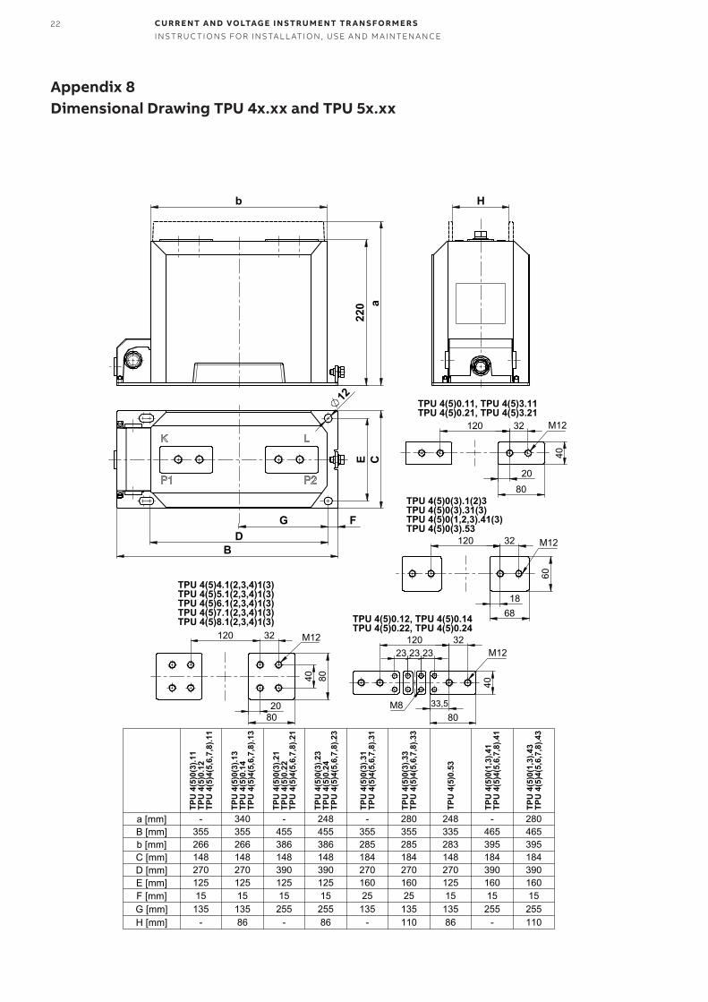
Appendix 8Dimensional Drawing TPU 4x.xx and TPU 5x.xx
220
b
a
12
C
B
FD
G
E
H
80
40
32 120
20
M12
TPU 4(5)0.11, TPU 4(5)3.11TPU 4(5)0.21, TPU 4(5)3.21
68
60
32 120
18
M12
TPU 4(5)0(3).1(2)3TPU 4(5)0(3).31(3)TPU 4(5)0(1,2,3).41(3)TPU 4(5)0(3).53
80
40
32 120
33,5
23 23 23 M12
M8
TPU 4(5)0.12, TPU 4(5)0.14TPU 4(5)0.22, TPU 4(5)0.24
80
80
32 120
40
20
M12
TPU 4(5)4.1(2,3,4)1(3)TPU 4(5)5.1(2,3,4)1(3)TPU 4(5)6.1(2,3,4)1(3)TPU 4(5)7.1(2,3,4)1(3)TPU 4(5)8.1(2,3,4)1(3)
TPU
4(5
)0(3
).11
TPU
4(5
)0.1
2 T
PU 4
(5)4
(5,6
,7,8
).11
TPU
4(5
)0(3
).13
TPU
4(5
)0.1
4 T
PU 4
(5)4
(5,6
,7,8
).13
TPU
4(5
)0(3
).21
TPU
4(5
)0.2
2 T
PU 4
(5)4
(5,6
,7,8
).21
TPU
4(5
)0(3
).23
TPU
4(5
)0.2
4 T
PU 4
(5)4
(5,6
,7,8
).23
TPU
4(5
)0(3
).31
TPU
4(5
)4(5
,6,7
,8).3
1
TPU
4(5
)0(3
).33
TPU
4(5
)4(5
,6,7
,8).3
3
TPU
4(5
)0.5
3
TPU
4(5
)0(1
,3).4
1 T
PU 4
(5)4
(5,6
,7,8
).41
TPU
4(5
)0(1
,3).4
3 T
PU 4
(5)4
(5,6
,7,8
).43
a [mm] - 340 - 248 - 280 248 - 280B [mm] 355 355 455 455 355 355 335 465 465b [mm] 266 266 386 386 285 285 283 395 395C [mm] 148 148 148 148 184 184 148 184 184D [mm] 270 270 390 390 270 270 270 390 390E [mm] 125 125 125 125 160 160 125 160 160F [mm] 15 15 15 15 25 25 15 15 15G [mm] 135 135 255 255 135 135 135 255 255H [mm] - 86 - 86 - 110 86 - 110
23
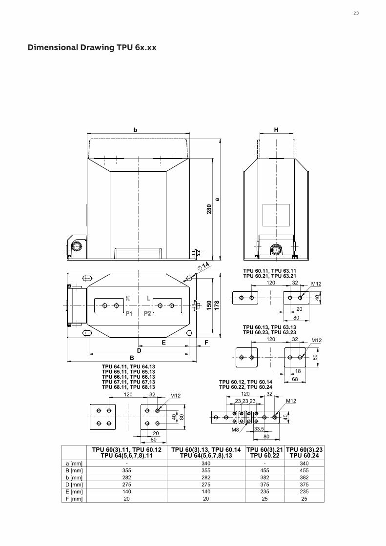
Dimensional Drawing TPU 6x.xx
280
b
a
D B
F
150
1
78
14
E
H
80 4
0
32 120
20
M12
TPU 60.11, TPU 63.11TPU 60.21, TPU 63.21
68
60
32 120
18
M12
TPU 60.13, TPU 63.13TPU 60.23, TPU 63.23
80
40
32 120
33,5
23 23 23 M12
M8
TPU 60.12, TPU 60.14TPU 60.22, TPU 60.24
80
80
32 120
40
20
M12
TPU 64.11, TPU 64.13TPU 65.11, TPU 65.13TPU 66.11, TPU 66.13TPU 67.11, TPU 67.13TPU 68.11, TPU 68.13
TPU 60(3).11, TPU 60.12 TPU 64(5,6,7,8).11
TPU 60(3).13, TPU 60.14 TPU 64(5,6,7,8).13
TPU 60(3).21 TPU 60.22
TPU 60(3).23 TPU 60.24
a [mm] - 340 - 340B [mm] 355 355 455 455b [mm] 282 282 382 382D [mm] 275 275 375 375E [mm] 140 140 235 235F [mm] 20 20 25 25
24 CU R R E NT A N D VO LTAG E I N S TR U M E NT TR A N S FO R M E R SI NS TR U C TI O NS FO R I NS TA L L ATI O N , USE A N D M A I NTEN A N CE
280
407
6
a
178
14
235 25 375
150
455
110
80
80
32 120
40
20
M12
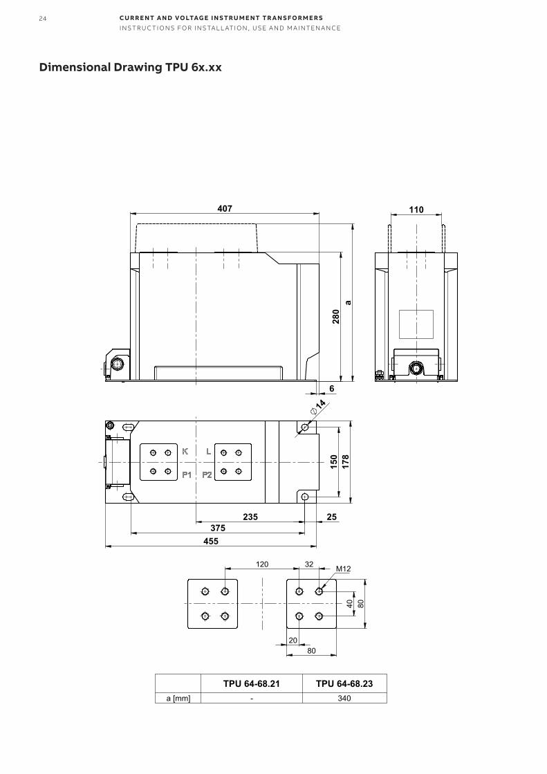
TPU 64-68.21 TPU 64-68.23a [mm] - 340
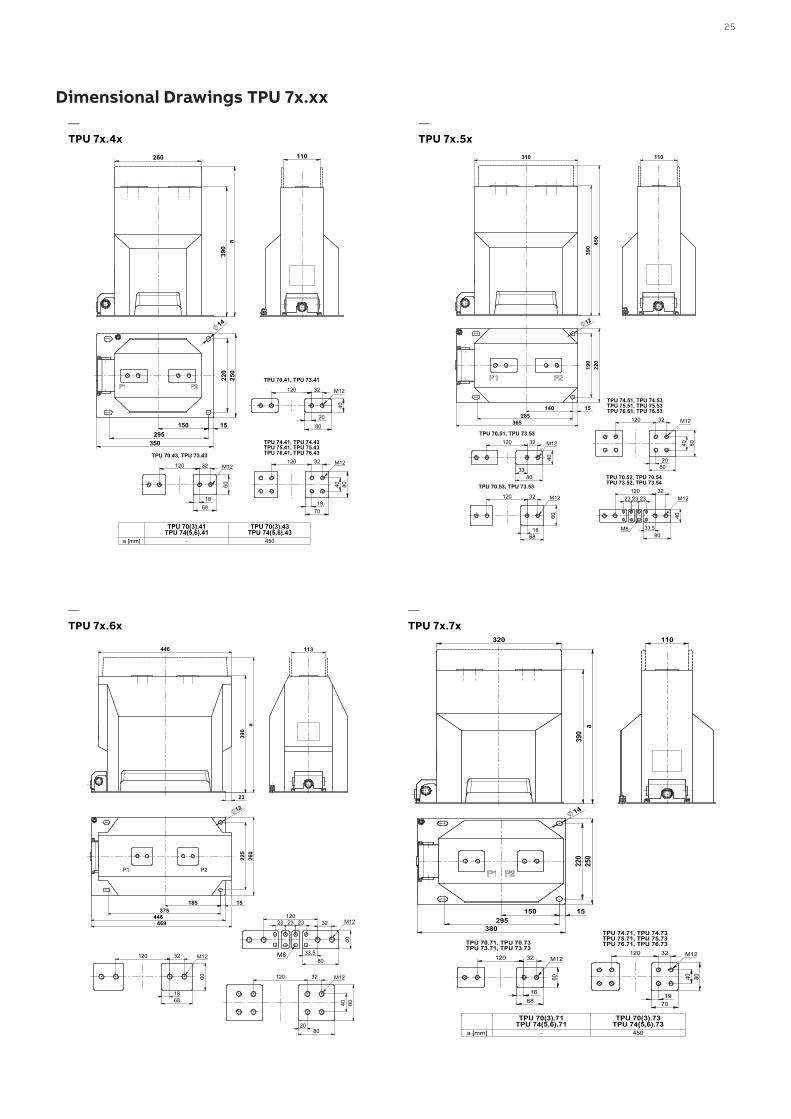
Dimensional Drawing TPU 6x.xx
25
310
390 4
50
220
190
140285
365
15
12
110
80
40
32 120
33
M12
TPU 70.51, TPU 73.53
68
60
32 120
18
M12
TPU 70.53, TPU 73.53
80
40
32 120
33,5
23 23 23 M12
M8
TPU 70.52, TPU 70.54TPU 73.52, TPU 73.54
80
80
32 120
40
20
M12
TPU 74.51, TPU 74.53TPU 75.51, TPU 75.53TPU 76.51, TPU 76.53
446
390
23
a
260
225
12
37515
446
185
469
P1 P2
113
68
60
32 120
18
M12 80
40
32 120
33,5
23 23 23 M12
M8
80
80
32 120
40
20
M12
260
390
a
250
350
220
15 150 295
14
70
80
32 120
40
19
M12
TPU 74.41, TPU 74.43TPU 75.41, TPU 75.43TPU 76.41, TPU 76.43
110
80
40
32 120
20
M12
TPU 70.41, TPU 73.41
68
60
32 120
18
M12
TPU 70.43, TPU 73.43
TPU 70(3).41TPU 74(5,6).41
TPU 70(3).43TPU 74(5,6).43
a [mm] - 450
390
320
a
220
2
50
14
15 150 295
380
110
68
60
32 120
18
M12
TPU 70.71, TPU 70.73TPU 73.71, TPU 73.73
70
80
32 120
40
19
M12
TPU 74.71, TPU 74.73TPU 75.71, TPU 75.73TPU 76.71, TPU 76.73
TPU 70(3).71TPU 74(5,6).71
TPU 70(3).73TPU 74(5,6).73
a [mm] - 450
Dimensional Drawings TPU 7x.xx —TPU 7x.5x
—TPU 7x.6x
—TPU 7x.4x
—TPU 7x.7x
26 CU R R E NT A N D VO LTAG E I N S TR U M E NT TR A N S FO R M E R SI NS TR U C TI O NS FO R I NS TA L L ATI O N , USE A N D M A I NTEN A N CE
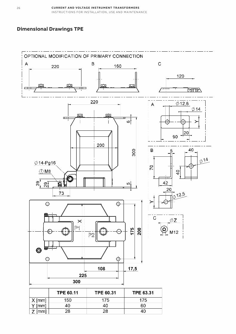
Dimensional Drawings TPE
27
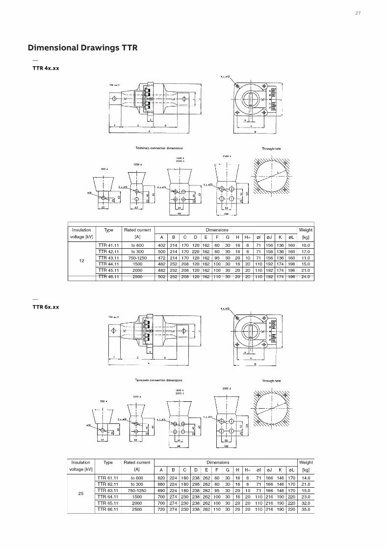
Dimensional Drawings TTR—TTR 4x.xx
—TTR 6x.xx
28 CU R R E NT A N D VO LTAG E I N S TR U M E NT TR A N S FO R M E R SI NS TR U C TI O NS FO R I NS TA L L ATI O N , USE A N D M A I NTEN A N CE
Dimension WeightkgType
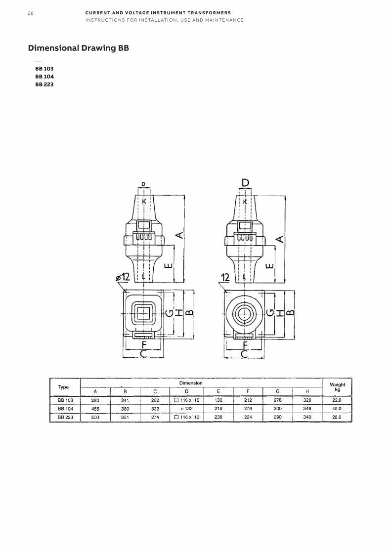
Dimensional Drawing BB—BB 103BB 104BB 223
29
258
220
R100
672 11
4
30°30°
8467 110
180
40
23
23
23
160 135
84
78
7
7
M5*
M5*
260
120
90
80
M10
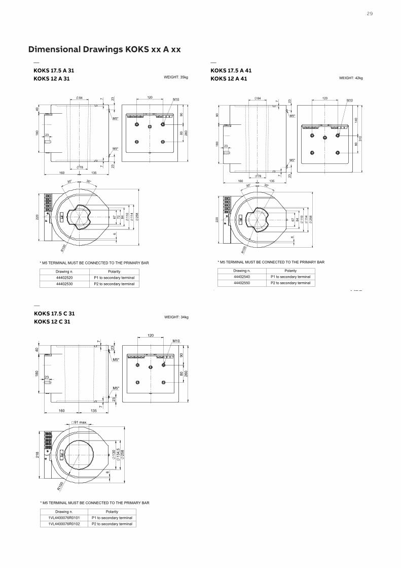
* M5 TERMINAL MUST BE CONNECTED TO THE PRIMARY BAR
Drawing n. Polarity44402520 P1 to secondary terminal44402530 P2 to secondary terminal
KOKS 12A31KOKS 17,5A31
WEIGHT: 35kg
11
4
R10
0
6
220
25
8
8467 110
30° 30°
90
180
23
23
23
7
7
84
78 160 135
M5*
M5*
120
80
140
3
10
M10
* M5 TERMINAL MUST BE CONNECTED TO THE PRIMARY BAR
Drawing n. Polarity44402540 P1 to secondary terminal44402550 P2 to secondary terminal
KOKS 12A41KOKS 17,5A41
WEIGHT: 42kg
Dimensional Drawings KOKS xx A xx—KOKS 17.5 A 31KOKS 12 A 31
—KOKS 17.5 A 41KOKS 12 A 41
120 M10
90
80
260
180
4
0
160 135
7
7
23
23
23
M5*
M5*
218
6
25
8
13
0
134,
5
R10
0
91 max.
* M5 TERMINAL MUST BE CONNECTED TO THE PRIMARY BAR
Drawing n. Polarity1VL4400076R0101 P1 to secondary terminal1VL4400076R0102 P2 to secondary terminal
KOKS 12C31KOKS 17,5C31
WEIGHT: 34kg
—KOKS 17.5 C 31KOKS 12 C 31
30 CU R R E NT A N D VO LTAG E I N S TR U M E NT TR A N S FO R M E R SI NS TR U C TI O NS FO R I NS TA L L ATI O N , USE A N D M A I NTEN A N CE
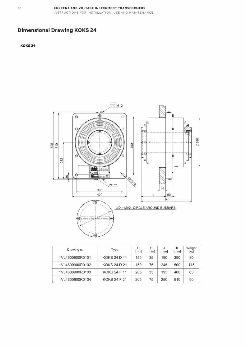
Dimensional Drawing KOKS 24
—KOKS 24
31
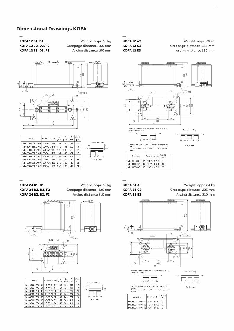
Dimensional Drawings KOFA
Weight: appr. 18 kg Creepage distance: 160 mm
Arcing distance 150 mm
Weight: appr. 18 kg Creepage distance: 220 mm
Arcing distance 210 mm
—KOFA 12 B1, D1KOFA 12 B2, D2, F2KOFA 12 B3, D3, F3
—KOFA 24 B1, D1KOFA 24 B2, D2, F2KOFA 24 B3, D3, F3
—KOFA 12 A3KOFA 12 C3KOFA 12 E3
—KOFA 24 A3KOFA 24 C3KOFA 24 E3
Weight: appr. 20 kg Creepage distance: 165 mm
Arcing distance 150 mm
Weight: appr. 24 kg Creepage distance: 225 mm
Arcing distance 210 mm
32 CU R R E NT A N D VO LTAG E I N S TR U M E NT TR A N S FO R M E R SI NS TR U C TI O NS FO R I NS TA L L ATI O N , USE A N D M A I NTEN A N CE
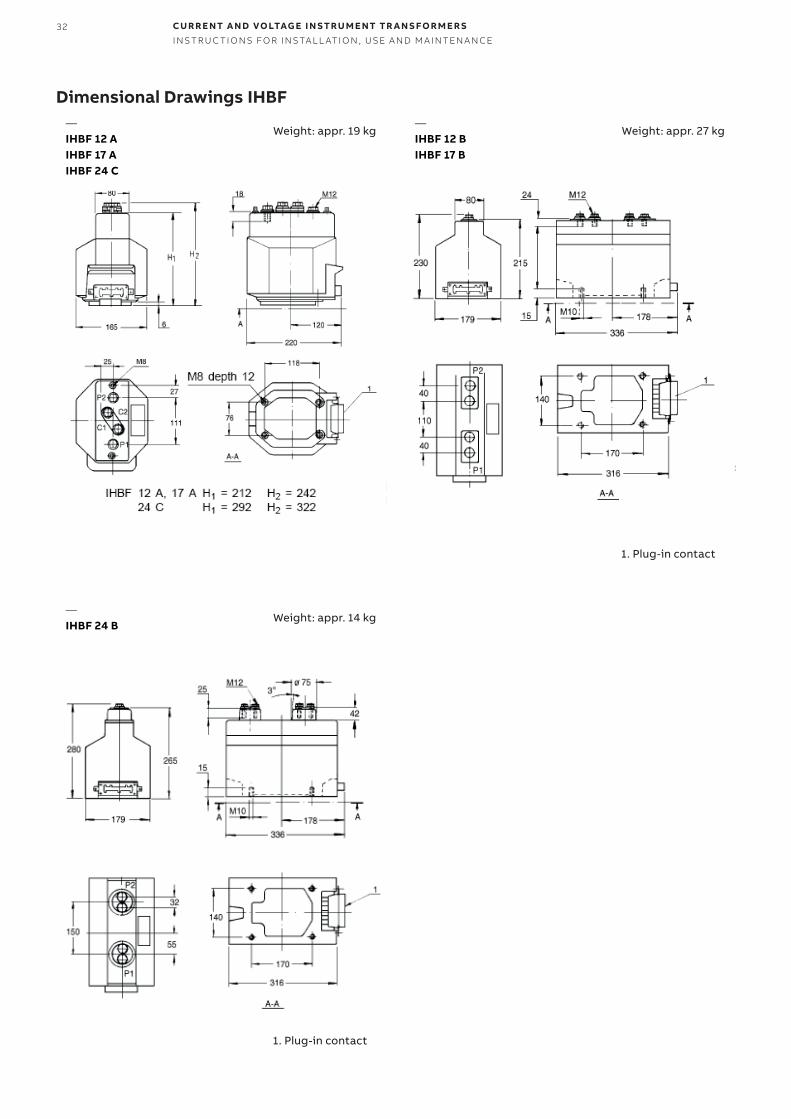
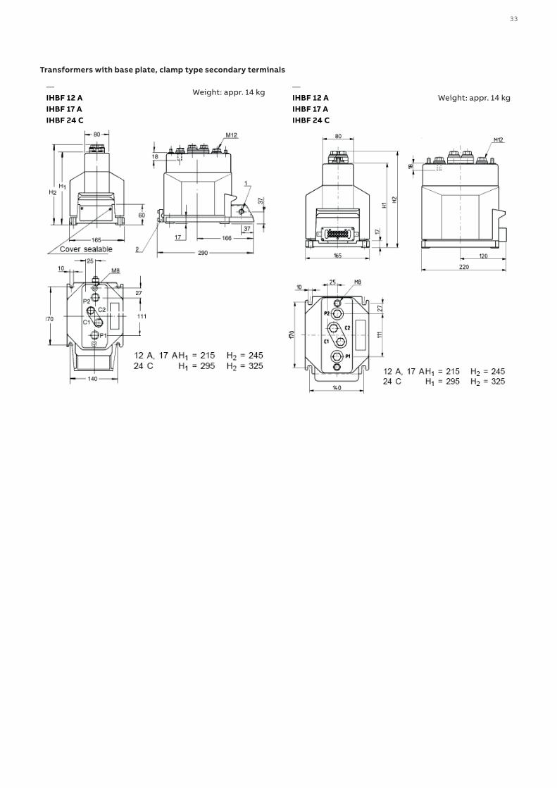
Dimensional Drawings IHBF
Weight: appr. 19 kg
Weight: appr. 14 kg
—IHBF 12 AIHBF 17 AIHBF 24 C
—IHBF 24 B
—IHBF 12 B IHBF 17 B
Weight: appr. 27 kg
1. Plug-in contact
1. Plug-in contact
33
Transformers with base plate, clamp type secondary terminals
—IHBF 12 AIHBF 17 AIHBF 24 C
—IHBF 12 AIHBF 17 AIHBF 24 C
Weight: appr. 14 kgWeight: appr. 14 kg
34 CU R R E NT A N D VO LTAG E I N S TR U M E NT TR A N S FO R M E R SI NS TR U C TI O NS FO R I NS TA L L ATI O N , USE A N D M A I NTEN A N CE
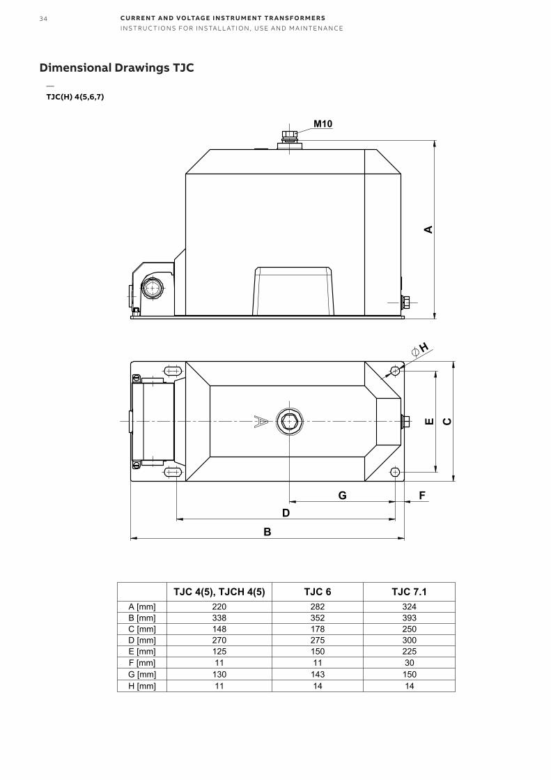
Dimensional Drawings TJC
A
M10
E C
B
G D
F
H
TJC 4(5), TJCH 4(5) TJC 6 TJC 7.1A [mm] 220 282 324B [mm] 338 352 393C [mm] 148 178 250D [mm] 270 275 300E [mm] 125 150 225F [mm] 11 11 30G [mm] 130 143 150H [mm] 11 14 14
—TJC(H) 4(5,6,7)
35
300
20
28 38
26
M8 Pg16
14
314
704
324
55
M10
225
225
4x14
30030
393
250
150
107
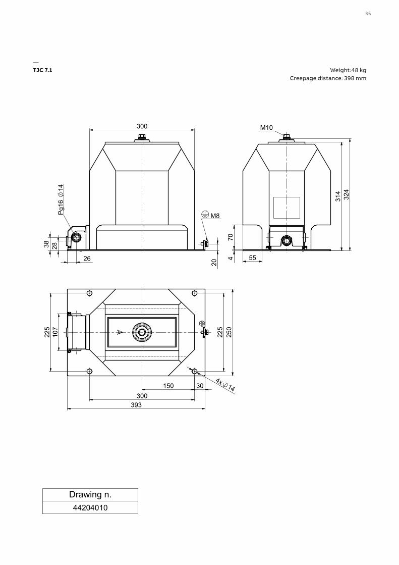
Drawing n.44204010
TJC 7.1 WEIGHT: 48kgCREEPAGE DISTANCE: 398mm
Weight:48 kg Creepage distance: 398 mm
—TJC 7.1
36 CU R R E NT A N D VO LTAG E I N S TR U M E NT TR A N S FO R M E R SI NS TR U C TI O NS FO R I NS TA L L ATI O N , USE A N D M A I NTEN A N CE
45300
60°
180213
28 26
38
M8 Pg16
14 30
831
4
55
324
60°
45
70
R15
4
M10
250
107
1
60
160
1
90
360 20 160
13
4x14
393
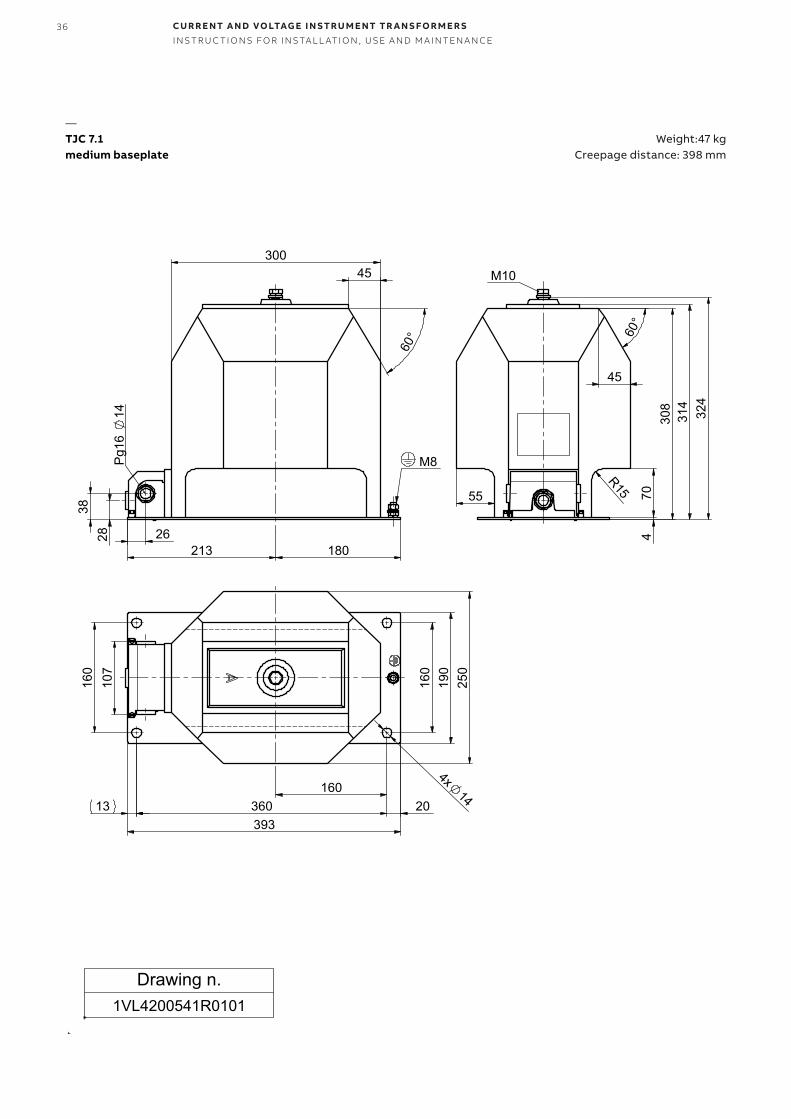
medium baseplate
Drawing n.1VL4200541R0101
TJC 7.1 WEIGHT: 47kgCREEPAGE DISTANCE: 398mm
Weight:47 kg Creepage distance: 398 mm
—TJC 7.1medium baseplate
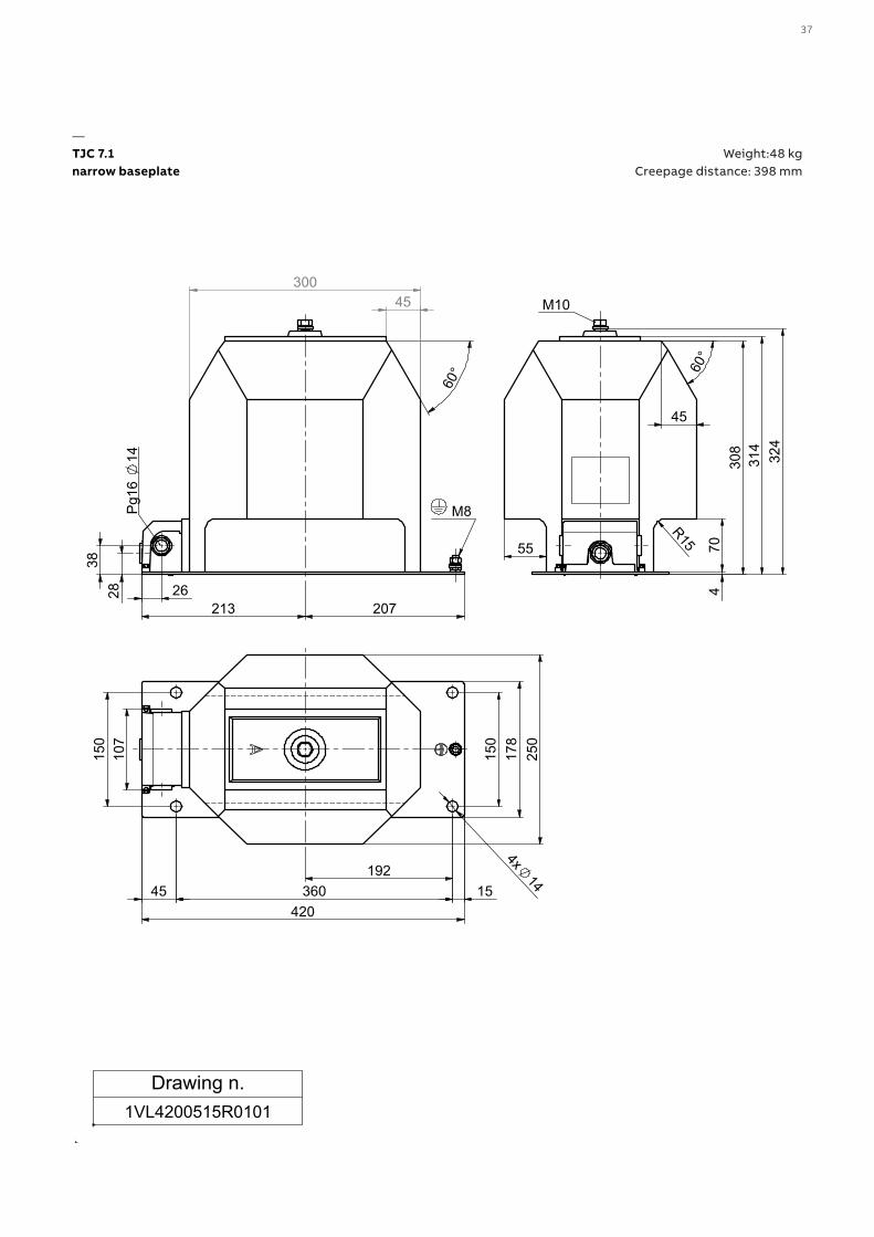
37
45300
60°
207213
28 26
38
M8 Pg16
14 30
831
4
4
55
324
60°
45
70
R15
M10
192
420 15 360 45
150
1
78
250
150
1
07
4x14
Drawing n.1VL4200515R0101
TJC 7.1 WEIGHT: 48kgCREEPAGE DISTANCE: 398mm
Weight:48 kg Creepage distance: 398 mm
—TJC 7.1narrow baseplate
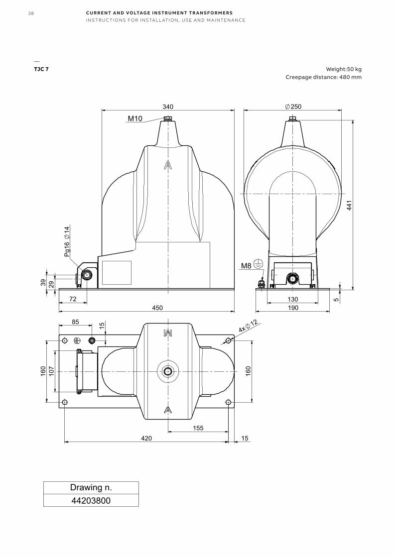
38 CU R R E NT A N D VO LTAG E I N S TR U M E NT TR A N S FO R M E R SI NS TR U C TI O NS FO R I NS TA L L ATI O N , USE A N D M A I NTEN A N CE
190
5130
250
441
M8
340
450
29 39
72
Pg1
6 14
M10
420
160
4x12 85
15
155 15
107
1
60
Drawing n.44203800
TJC 7 WEIGHT: 50kgCREEPAGE DISTANCE: 480mm
Weight:50 kg Creepage distance: 480 mm
—TJC 7
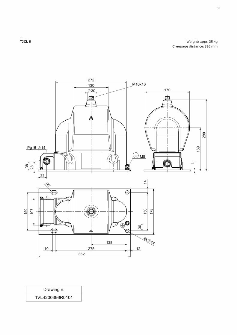
39
272
28 38
33
30 130
M8
M10x16
Pg16 14
4
170
280
1
69
178
R7
352
2x14
10 275 12
150
1
4 3
0
150
138
107
Drawing n.
1VL4200396R0101
TJCL 6 WEIGHT: 25kgCREEPAGE DISTANCE: 326mm
Weight: appr. 25 kg Creepage distance: 326 mm
—TJCL 6
40 CU R R E NT A N D VO LTAG E I N S TR U M E NT TR A N S FO R M E R SI NS TR U C TI O NS FO R I NS TA L L ATI O N , USE A N D M A I NTEN A N CE
202
10394
38
28
26
M8
M10
Pg16 14
120
190
4
70
155
4x8,5
253
85 70 30
106
107
15
12
120
Drawing n.
1VL4200252R0101
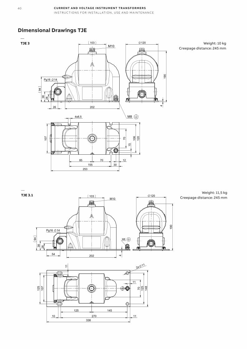
TJE 3TJE 4
WEIGHT: 10kgCREEPAGE DISTANCE: 245mm
202
103
94
4
28 38
54
M8
M10
Pg16 14
120
190
70125
125
148
2x 1111
145125
107
11
270 11 10 338
Drawing n.
1VL4200271R0101
TJE 3.1TJE 4.1
WEIGHT: 11,5kgCREEPAGE DISTANCE: 245mm
Dimensional Drawings TJE—TJE 3
—TJE 3.1
Weight: 10 kg Creepage distance: 245 mm
Weight: 11,5 kg Creepage distance: 245 mm
41
341
209
279
4
239
20
28 38
27
M8
Pg16 14
125
1227010
2x11
80
25 35
49033449
11
148 1
07
18 max.
fuse IEC 60282-1
41
OPTIONAL FOR CABLE CONNECTIONCREEPAGE DISTANCE: 418mm
M8
Drawing n.44204060
Drawing n.1VL4200418R0101 • • • • • •
300 34
0
4
270
506
28 38
27
Pg16 14
2x11
130 13
0 80
35 25
45605
324
10275
11
12
164 17
8
107
248
18 max.
fuse IEC 60282-1
41
OPTIONAL FOR CABLE CONNECTIONCREEPAGE DISTANCE: 566mm
M8
Drawing n.
44204070Drawing n.
1VL4200419R0101
TJP 6.0 WEIGHT: 42kgCREEPAGE DISTANCE: 548mm
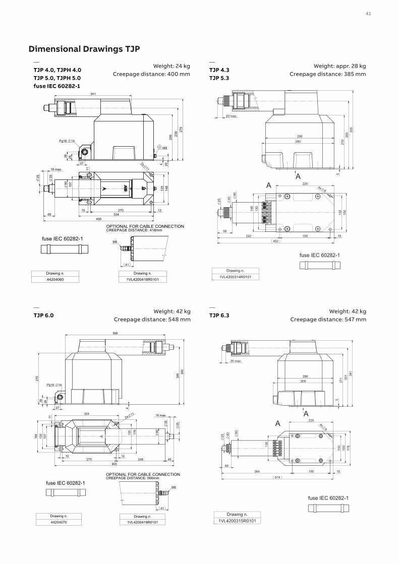
Dimensional Drawings TJP
Weight: 42 kg Creepage distance: 547 mm
—TJP 6.3
Weight: 24 kg Creepage distance: 400 mm
Weight: 42 kg Creepage distance: 548 mm
—TJP 4.0, TJPH 4.0TJP 5.0, TJPH 5.0 fuse IEC 60282-1
—TJP 6.0
—TJP 4.3TJP 5.3
Weight: appr. 28 kg Creepage distance: 385 mm
42 CU R R E NT A N D VO LTAG E I N S TR U M E NT TR A N S FO R M E R SI NS TR U C TI O NS FO R I NS TA L L ATI O N , USE A N D M A I NTEN A N CE
143
431
304
20
4209
342
39
22
M8
2xM8
Pg1
6 14
9615
017
8
2x14
14
1228010352 75
fuse JT6 300, 600mADrawing n.
44203980
TJP 6.1 WEIGHT: 42kgCREEPAGE DISTANCE: 342mm
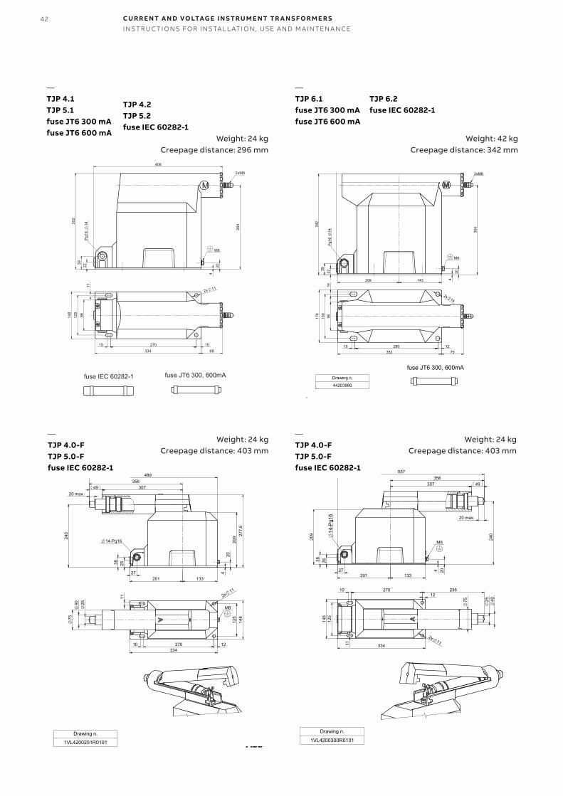
Weight: 24 kg Creepage distance: 296 mm
—TJP 4.1TJP 5.1fuse JT6 300 mAfuse JT6 600 mA
—TJP 6.1fuse JT6 300 mAfuse JT6 600 mA
Weight: 42 kg Creepage distance: 342 mm
240
49
277,
5
307356
489
209
4
28 38
27
20
133201
20 max.
14-Pg16
125
148
10 270334
4075
2x11
25
12
11
M8
Drawing n.
1VL4200251R0101
TJP 4.0-F WEIGHT: 24kgCREEPAGE DISTANCE: 403mm
Weight: 24 kg Creepage distance: 403 mm
—TJP 4.0-FTJP 5.0-Ffuse IEC 60282-1
49356
307
4 20
133 201
28 38
27
240
557
209
20 max.
14-P
g16
M8
27010
125
148
75 4025
235
11 334
2x11
12
Drawing n.
1VL4200300R0101
TJP 4.0-F WEIGHT: 24kgCREEPAGE DISTANCE: 403mm
Weight: 24 kg Creepage distance: 403 mm
—TJP 4.0-FTJP 5.0-Ffuse IEC 60282-1
TJP 4.2TJP 5.2fuse IEC 60282-1
TJP 6.2fuse IEC 60282-1
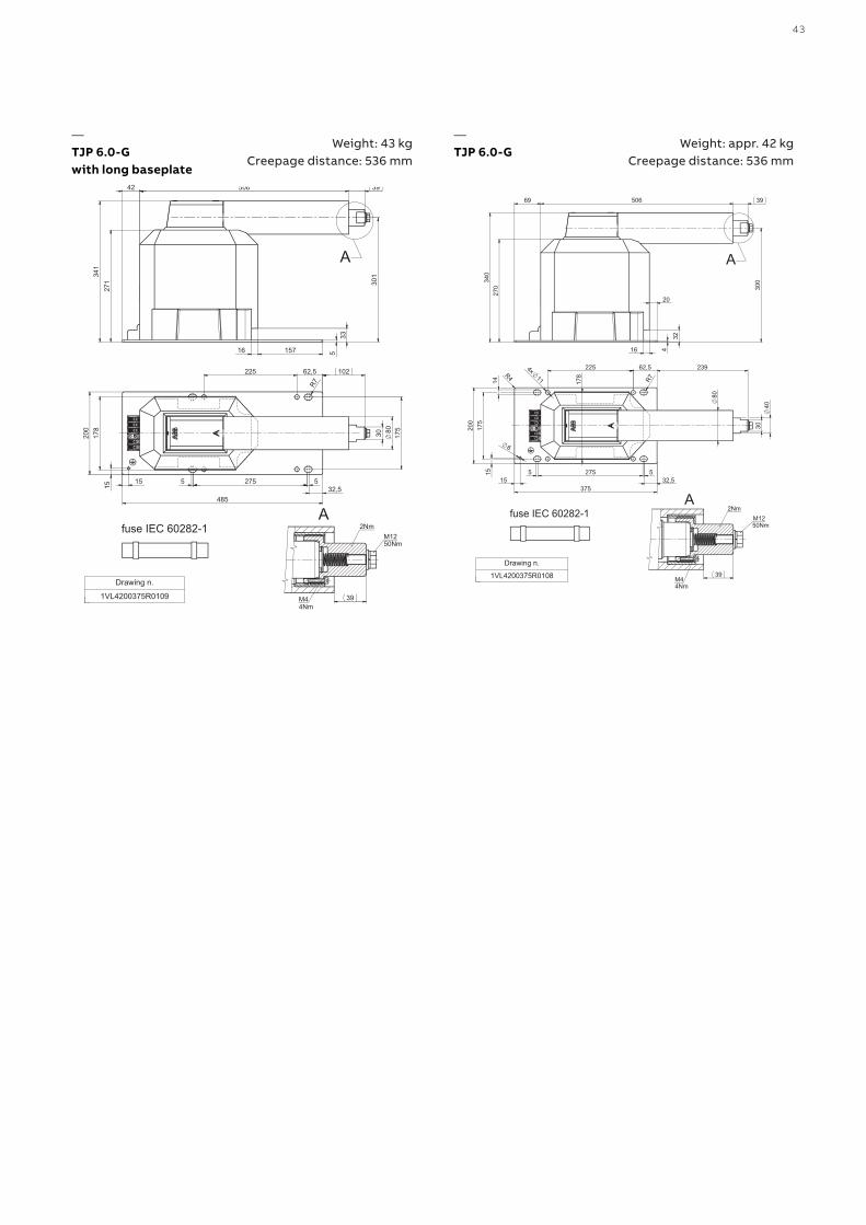
43
Weight: 43 kg Creepage distance: 536 mm
—TJP 6.0-Gwith long baseplate
Weight: appr. 42 kg Creepage distance: 536 mm
—TJP 6.0-G
44 CU R R E NT A N D VO LTAG E I N S TR U M E NT TR A N S FO R M E R SI NS TR U C TI O NS FO R I NS TA L L ATI O N , USE A N D M A I NTEN A N CE
30
20
666 612
28
38
26
300
A
M8 Pg16 14
4
364
4
14
308
230 45
70
107
393 300 30
696
4x14
225
2
50
10
0
84
25
54
18 max.
A
fuse IEC 60282-1
Drawing n.1VL4200508R0101
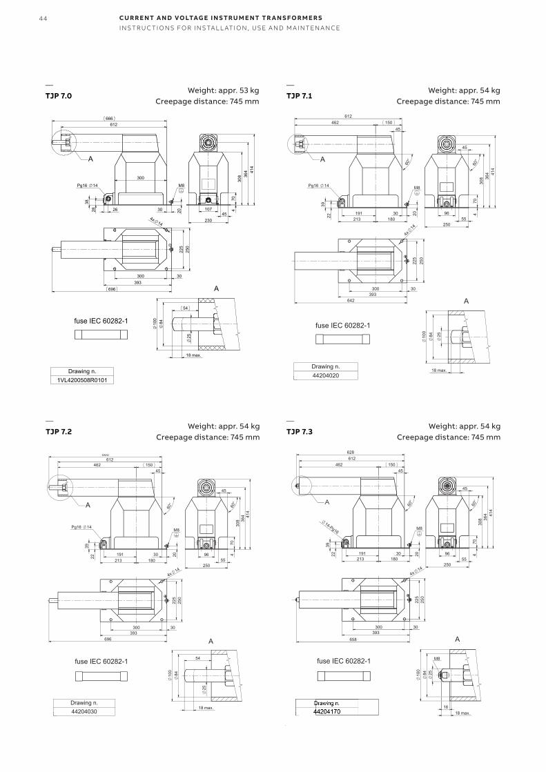
TJP 7.0 WEIGHT: 53kgCREEPAGE DISTANCE: 745mm
—TJP 7.1
Weight: appr. 54 kg Creepage distance: 745 mm
Weight: appr. 54 kg Creepage distance: 745 mm
Weight: appr. 54 kg Creepage distance: 745 mm
—TJP 7.2
—TJP 7.3
—TJP 7.0
Weight: appr. 53 kg Creepage distance: 745 mm

45
A
M10
E C
G
I D
F
B
J
H
TDC 4(5) TDC 6A [mm] 220 280B [mm] 338 352C [mm] 148 178D [mm] 270 275E [mm] 125 150F [mm] 11 11G [mm] 110 130H [mm] 100 165I [mm] 88 60J [mm] 11 14
Dimensional Drawings TDC—TDC 4(5,6)
46 CU R R E NT A N D VO LTAG E I N S TR U M E NT TR A N S FO R M E R SI NS TR U C TI O NS FO R I NS TA L L ATI O N , USE A N D M A I NTEN A N CE
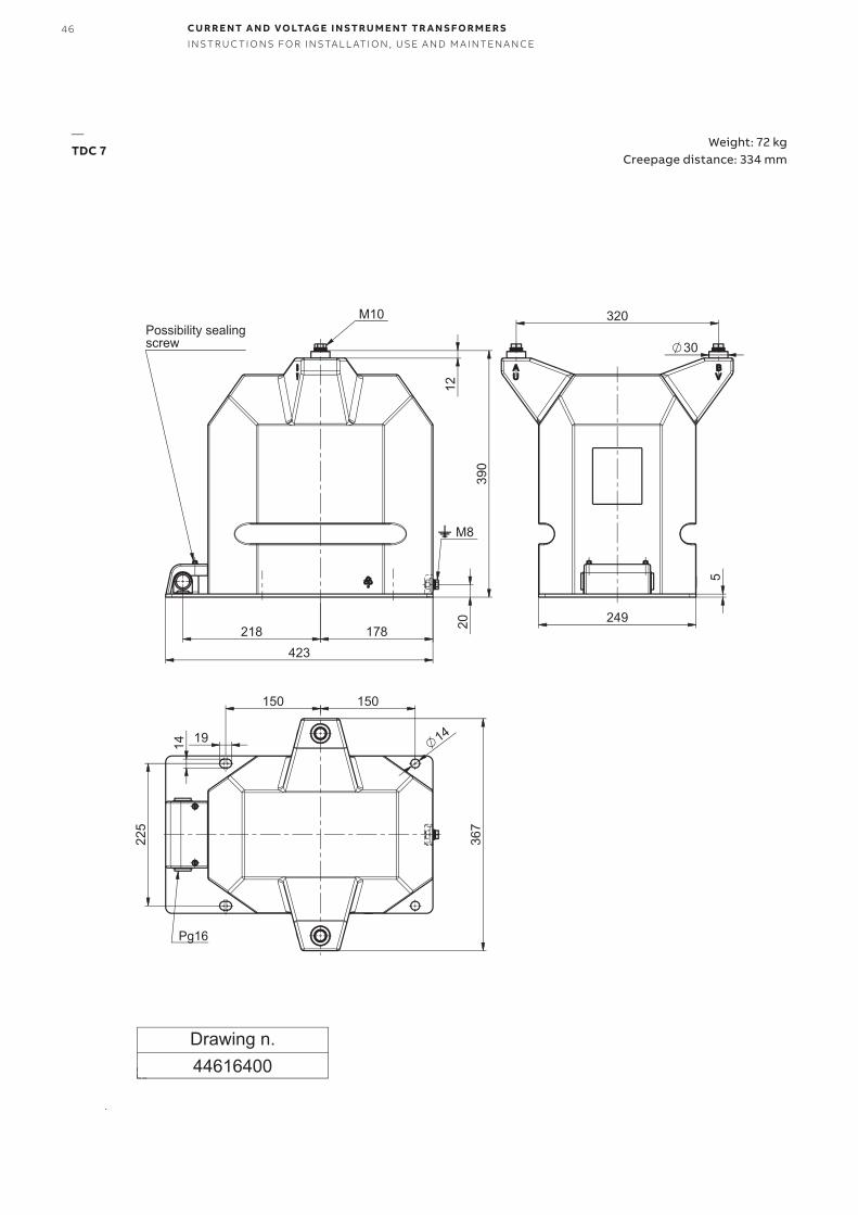
Weight: 72 kg Creepage distance: 334 mm
—TDC 7
47
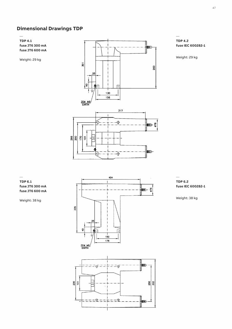
—TDP 4.1 fuse JT6 300 mAfuse JT6 600 mA Weight: 29 kg
—TDP 6.1 fuse JT6 300 mAfuse JT6 600 mA Weight: 38 kg
—TDP 4.2 fuse IEC 600282-1
Weight: 29 kg
—TDP 6.2 fuse IEC 600282-1
Weight: 38 kg
Dimensional Drawings TDP
48 CU R R E NT A N D VO LTAG E I N S TR U M E NT TR A N S FO R M E R SI NS TR U C TI O NS FO R I NS TA L L ATI O N , USE A N D M A I NTEN A N CE
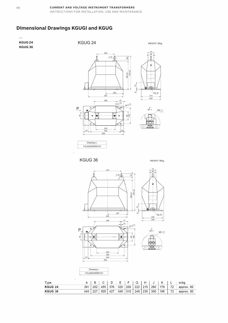
—KGUG 24KGUG 36
Dimensional Drawings KGUGI and KGUG
49
215
728
222
58 73
Pg 16
100
376
±2
10
202 391
45
320
±2
455
179
260
37
95
220 340 32
78
4x 11
72 14
P PM1:1 M8
Drawing n.
1VL4200392R0101
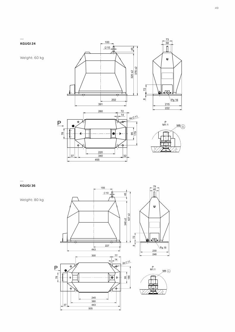
KGUGI 24 WEIGHT:60kg
230248
7940
728
Pg 16
348
±2 427
±245
443227
10
155
505
380245
95 186
300
37 443
78
77
4x 11 14
P PM1:1 M8
Drawing n.
1VL4200394R0101
KGUGI 36 WEIGHT: 80kg
—KGUGI 24
Weight: 60 kg
—KGUGI 36
Weight: 80 kg
50 CU R R E NT A N D VO LTAG E I N S TR U M E NT TR A N S FO R M E R SI NS TR U C TI O NS FO R I NS TA L L ATI O N , USE A N D M A I NTEN A N CE
35
346
49
4
75 13
M8
175
10
fuse JT6 300, 600mA
EXTERNAL FUSE COVER 17,5kV
—External fuse holder up to 17.5 kV
35
346
49
4
75 8
M8
175
10
fuse JT6 300, 600mA
EXTERNAL FUSE COVER 25kV
—External fuse holder up to 25 kV
fuse JT6 300 mA 1VL4200499R0101
fuse JT6 600 mA 1VL4200499R0102
fuse JT6 300 mA 1VL4200499R0201
fuse JT6 600 mA 1VL4200499R0202
51
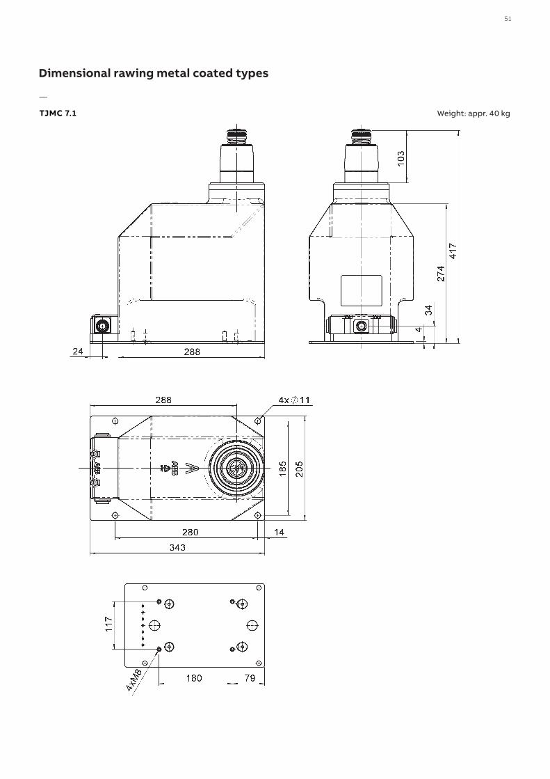
Dimensional rawing metal coated types
Weight: appr. 40 kg
—
TJMC 7.1
52 CU R R E NT A N D VO LTAG E I N S TR U M E NT TR A N S FO R M E R SI NS TR U C TI O NS FO R I NS TA L L ATI O N , USE A N D M A I NTEN A N CE
e
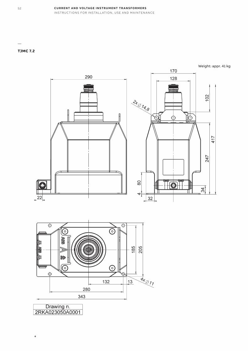
Weight: appr. 41 kg
—
TJMC 7.2
53
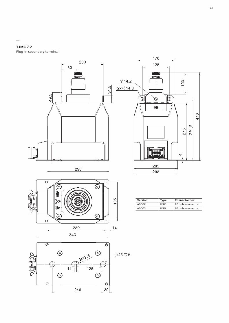
—
TJMC 7.2Plug-in secondary terminal
Version Type Connector boxA0002 W12 12 pole connectorA0003 W10 10 pole connector
54 CU R R E NT A N D VO LTAG E I N S TR U M E NT TR A N S FO R M E R SI NS TR U C TI O NS FO R I NS TA L L ATI O N , USE A N D M A I NTEN A N CE
442
166
300
106
376
58°
R5,50
R5,50
116
9,4
71
71
195
204
152
,8
376
186 4
189
70
291
426
,50
106
186
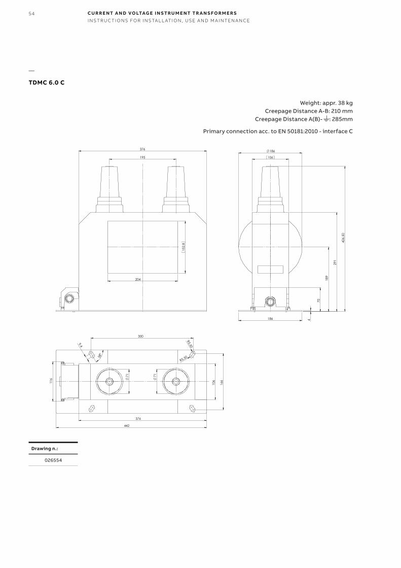
TDMC 6.0 C Weight: appx. 40kg
Drawing n.: 026554
Weight: appr. 38 kg Creepage Distance A-B: 210 mm
Creepage Distance A(B)- : 285mm
Primary connection acc. to EN 50181:2010 - interface C
Drawing n.:
026554
—
TDMC 6.0 C

1VLM
00
06
10 R
ev.2
4, e
n 2
022
.02.
03
—N O T EWe reserve the right to make technical changes or modify the contents of this docu-ment without prior notice. With regard to purchase orders, the agreed particulars shall prevail. ABB does not accept any responsibil-ity whatsoever for potential errors or possi-ble lack of information in this document.
We reserve all rights in this document and in the subject matter and illustrations con-tained therein. Any reproduction, disclosureto third parties or utilization of its contents - in whole or in parts - is forbidden without prior written consent of ABB.
Copyright© 2022 ABBAll rights reserved
—C O N TA C T U SABB s.r.o.ELDS BrnoVidenska 117, 619 00 Brno, Czech Republic Tel.: +420 547 152 021 +420 547 152 854 Fax: +420 547 152 626 E-mail: [email protected]
www.abb.com
Related Documents