GEK-99344 INSTRUCTIONS DIFFERENTIAL REY WITH PERCENTAGE RESTRAINT PE NBD16A GEK-993448 Protection & Control GE Technology Center 205 Great Valley Paray Malvern, PA 19355-1337 www . ElectricalPartManuals . com www . ElectricalPartManuals . com

Welcome message from author
This document is posted to help you gain knowledge. Please leave a comment to let me know what you think about it! Share it to your friends and learn new things together.
Transcript

GEK-99344
INSTRUCTIONS
DIFFERENTIAL RELAY WITH PERCENTAGE RESTRAINT
TYPE NBD16A
GEK-993448
Protection & Control
GE Technology Center 205 Great Valley Parkway Malvern, PA 19355-1337 www .
Elec
tricalP
artM
anua
ls . c
om
www . El
ectric
alPar
tMan
uals
. com

These instructions do not purport to cover all details or variations in equipment nor provide for every possible contingency to be met in connection with installation, operation or maintenance. Should further infonnation be desired or should particular problems arise which are not covered sufficiently for the purchaser's purposes, the matter should be referred to the General Electric Company.
To the extent required the products described here in meet applicable ANSI, IEEE and NEMA standards; but no such assurance is given with respect to local codes and ordinances because they vary greatly.
8/91
www . El
ectric
alPar
tMan
uals
. com
www . El
ectric
alPar
tMan
uals
. com

GEK-99344
TABLE OF CONTENTS
DIFFERENTIAL RELAY WITH PERCENTAGE RESTRAINT DESCRIPTION APPLICATION RATINGS
Continuous rating Short time rating (thermal) Short time (electrical) AUXILIARY RELAY CONTROL CIRCUIT CONTACTS
CHARACTERISTICS PICKUP AND OPERATING TIME PERCENTAGE DIFFERENTIAL CHARACTERISTICS
BURDENS CONSTRUCTION
CURRENT TRANSFORMERS THROUGH-CURRENT RESTRAINT CIRCUIT DIFFERENTIAL CURRENT CIRCUIT MAIN OPERATING UNIT CASE
RECEIVING, HANDLING AND STORAGE ACCEPTANCE TESTS
VISUAL INSPECTION MECHANICAL INSPECTION ELECfRICAL TESTS TEST FACILITIES
INSTALLATION PROCEDURE TESTS PICKUP THROUGH-CURRENT RESTRAINT DROPOUT OF MAIN UNIT LOCATION MOUNTING CONNECTIONS
ADJUSTMENTS TAP PLUG POSITIONING - Ratio Matching Adjustment UNBALANCE CURRENT MEASUREMENT PERCENT SLOPE SETTING
CALCULATION OF SETTINGS CURRENT TRANSFORMER RATIO ERROR PERCENT SLOPE SETTING
OPERATING PRINCIPLES TARGETS DISABLING TYPE NBD RELAYS
MAINTENANCE CONTACT CLEANING
PERIODIC CHECKS AND ROUTINE MAINTENANCE PICKUP THROUGH-CURRENT RESTRAINT
RENEWAL PARTS
3
PAGE 5 5 5 6 6 6 6 6 6 7 7 7 7 8 8 8 8 9 9 10 10 10 10 10 10 11 11 11 12 13 13 13 13 14 14 14 15 15 15 16 17 17 17 17 17 17 18 18 21
www . El
ectric
alPar
tMan
uals
. com
www . El
ectric
alPar
tMan
uals
. com

FIG
1 2 3 4 5 6
7 8 9 10 1 1
12
TABLE
I II III IV
GEK-99344
LIST OF FIGURES
TITLE
'fype NBD Relay, Out of Case, Front Right View Type NBD Relay, Out of Case, Rear Left View Operating Characteristics of the Type NBD Relay Operating Characteristics, Expanded Curve of Figure 3 Typical Time-Current Curves for Type NBD Relays Cross Section of Drawout Case Showing the Position of the Auxiliary Brush Elementary Diagram for NBD16A Relays Internal Connections Diagram for NBD16A Relays Test Connections Test Circuit for NBD Relays Differential Voltage Operating Characteristics of Type NBD Relays Outline and Panel Drilling Dimensions for Type NBD Relays
LIST OF TABLES
TITLE
NBD16A BURDENS PERCENT SLOPE SET POINTS TOTAL BURDEN FOR 60 HERTZ NBD16A RELAYS THROUGH CURRENT RESTRAINT TEST SETTINGS
4
PAGE
22 22 23 24 25 26
27 28 29 30 3 1
32
PAGE
7 13 16 20
www . El
ectric
alPar
tMan
uals
. com
www . El
ectric
alPar
tMan
uals
. com

GEK-99344
DIFFERENTIAL RELAY WITH PERCENTAGE RESTRAINT
TYPE NBD16A
DESCRIPTION
T¥P,e NBD relays are differential relays designed for bus protection. The relays are provided With percentage restraint, and use a sensitive polanzed unit as the operating element. Percentage restraint permits accurate discrimination between internal and external faults at high fault currents.
Each Type NBD relay is a single-phase unit. The NBD16A relay is designed for the protection of three circuit buses, and has tliree through-current restraint circuits and one differential current circuit.
Each NBD relay is mounted in an Ml size case. The internal connection diagram for the NBD16A relay is shown in Figure 8. Typical external connections are shown in Figure 7.
APPLICATION
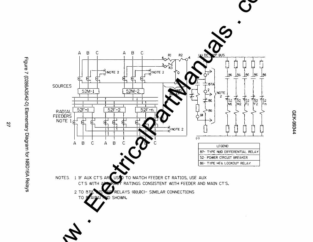
The NBD16A relay is designed to protect power distribution busses with one or two sources and radial load feeders. A typical elementary diagram is shown in Figure 7 for a two source bus (Ml and M2). If only one source exists, omit the connections shown for M2. If a normally closed bus tie breaker exists on the bus, two sets of NBD relays can be applied to selectively trip only the faulted bus section by opening the bus tie breaker and the source breaker associated with the faulted bus section.
If auxiliary Cf's are required for ratio matching the paralleled feeder CT's, auxiliary CT's of similar ratio accuracy should be used to avoid excessive error currents due to CT saturation on heavy through faults. The CTs on the source breakers should also be of similar accuracy class to avoid differential errors due to CT saturation. Differences in ratio between the source ITs and the parallel feeder Cf's can be accommodated by the NBD ratio matching taps and the percent slope tap settings.
It is _possible to use a single NBD relay with special auxiliary CTs to mix phase currents and provide protection with certain unbalance and sensitivity limitations. Refer to your GE representative for details.
The NBD can also be applied to;rotect long transformer leads when the associated breaker is remote from the transformer, an appropriate Cf's are available at the transformer and the associated remote circuit breaker. Only two NBD inputs are required for this application.
The current transformer ratios and relay taps should be selected to obtain the maximum sensitivity without risking thermal overload, or the possibility of misoperation of the relay or current transformers. Therefore, current transformer ratios should be selected with the following points in mind:
The lower the relay tap and the lower the CT ratio selected, the higher the sensitivity. However, the lowest CT ratio and the lowest relay tap may not be compatible with some of the following restrictions. Where a choice of increasing either the CT ratio or the relay tap is available, increase the CT ratio in preference to the relay tap.
Since the relay burden is likely to be small compared to the lead burden, increasing the CT ratio tends to improve the relative performance of the CTs as a result of reducing the maximum secondary fault current and increasing the accuracy of the CTs.
5 www . El
ectric
alPar
tMan
uals
. com
www . El
ectric
alPar
tMan
uals
. com

GEK-99344
The CT secondary current should not exceed the continuous thermal rating of the CT secondary winding.
The relay current corresponding to maximum primary load current should not exceed twice tap value, the thermal rating of the relay.
The cr ratios should be high enough that the secondary currents will not damage the relay under maximum internal fault conditions (refer to RATINGS).
The cr ratios should be selected to provide balanced secondary current on external faults. Since it is not always possible to matcli the secondary currents exactly by selection of current transformer ratios, ratio-matching taps are provided on the relay. Currents may usually be matched within five percent using tliese taps.
RATINGS
Continuous rating
The through-current transformer and differential current transformer will stand twice tap value for any combination of taps; or they will stand twice tap value if all but one of the restraint windings carry zero current, and the full restraint current, equal to twice tap value, flows through the differential current transformer.
Short time rating (thermal)
The short time (thermal) rating is 220 amperes for one second measured in the primary of any transformer of the Type NBD relay. Higher currents may be applied for shorter lengths of time in accordance with the following equation:
where: I = c.urre?t in amperes t = tlme m seconds
Short time (electrical)
I2t = 48,400
For the Type NBD16A relay, the sum of the multiples of t!!P current fed to the relay from the several sets of current transformers should not exceed 150. These: multiples should be calculated on the basis of RMS symmetrical fault current.
*AUXILIARY RELAY CONTROL CIRCUIT
The Type NBD16A relay is available for use with 125-250 volts, 48-125 volts, and 24-48 volts. A tap block is provided so that the relays may be used on either voltage of each dual rating.
CONTACTS
The NBD16A relay is provided with one set of open contacts. The current-closing rating of the contacts is 30 amperes for voltages not exceeding 250 volts . If more than one circuit breaker per set of contacts is to be tripped, or if the tripping current exceeds 30 amperes, an auxiliary relay must be used with the NBD relay. After tripping occurs, the tripping circuit of these relays should be opened by an auxiliary switch on the circuit breaker, or by other automatic means. A hand-reset relay is recommended, and normally used.
* Indicates revision
6 www . El
ectric
alPar
tMan
uals
. com
www . El
ectric
alPar
tMan
uals
. com

GEK-99344
C�CTERJSTICS
PICKUP AND OPERATING TIME
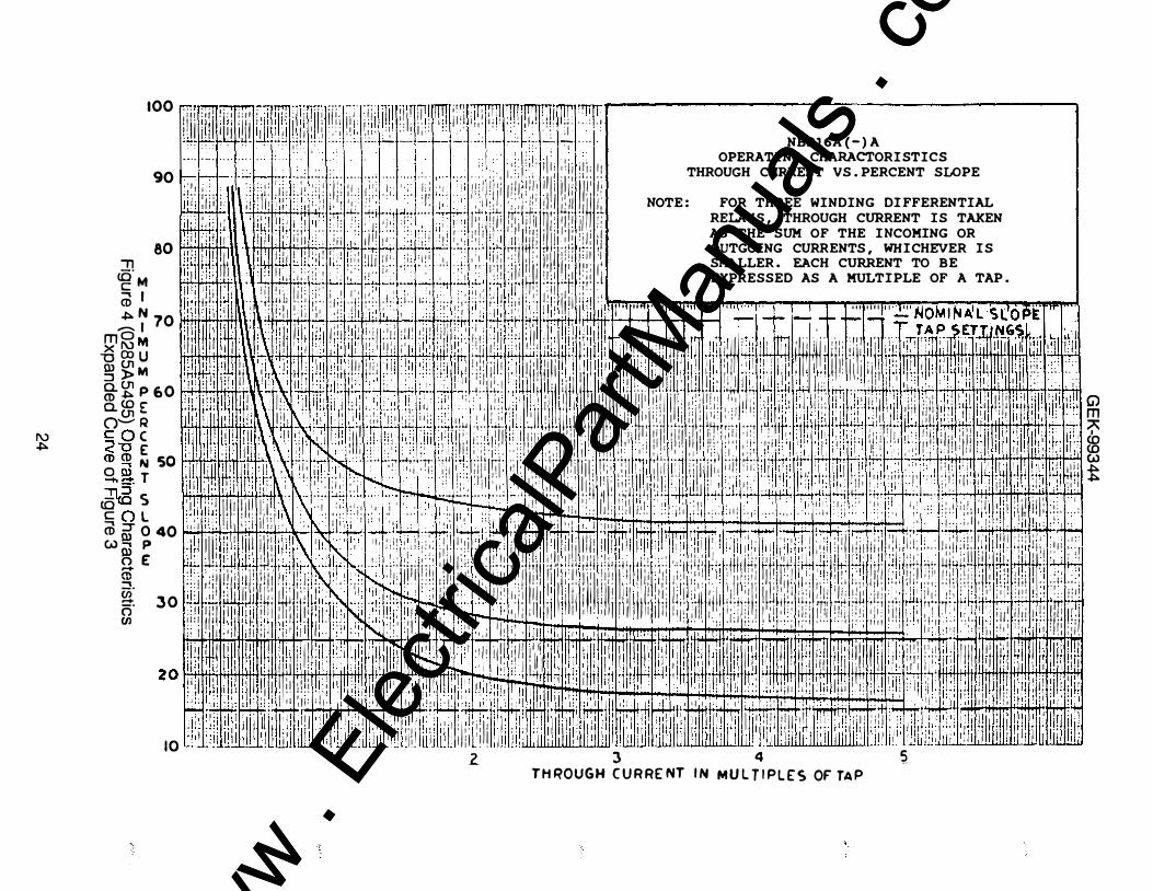
The operating characteristic is shown in Figures 3 and 4. The curve for various percentage slopes shows the percent slope versus the through-current flowing in the bus. The percentage s1ope IS a figure given to a particular percent slope tap setting, and indicates approximate slope characteristic. PickUp at zero restraint is approximately 30 percent of tap value (see Table I). Figure 4 is the same curve, except it is expanded from five to zero amperes.
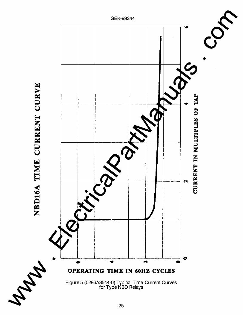
Curves of the operating time are shown plotted against differential current in Figure 5.
PERCENTAGE DIFFERENTIAL C�CTERISTICS
The I?ercentage differential characteristics are provided by through-current restraint circuits. In additiOn to the operating coil of the polarized unit, which 1s energized by the differential current of the line current transformers, the relay is equipped with a restraining coil, that is indirectly energized by the transformer secondary currents themselves. For the relay to operate, the current transformer secondary currents must be unbalanced by a certain minimum percentage determined by the relay slope setting (as shown in Figures 3 and 4). This characteristic is necessary to prevent false operation on through-fault currents. High currents saturate the cores of the current transformers and cause their ratios to change, with the result that the that the secondary currents become unbalanced. Percentage restraint is also needed to prevent operation by the unbalanced currents caused by imperfect matching of the secondary currents.
BURDENS
Note that burdens and minimum pickup values are substantially independent of the percent slope settings, and are all approximately 100 percent power factor. The f1gures given are the burdens imposed on each current transformer at 5.0 amperes.
TAP SETTING
AMPS
2.9 3.2 3.5 3.8 4.2 4.6 5.0 8.7
** *** ****
ZERO RESTRAINT PICKUP****
AMPS
0.87 0.96 1.05 1.14 1.26 1.38 1.50 2.61
TABLE I - NBD16A BURDENS
OPERATING CIRCUIT** 60 HERTZ RELAYS*** BURDEN IMPEDANCE
VA OHMS
3.2 2.7 2.4 2.0 1.9 1.6 1.5 0.7
0. 128 0. 108 0.096 0.080 0.076 0.064 0.060 0.028
RESTRAINT CIRCUIT 60 HERTZ RELAYS*** BURDEN IMPEDANCE
VA OHMS
1.3 1.2 1. 1 1.0 0.9 0.8 0.7 0.5
0.052 0.048 0.044 0.040 0.036 0.032 0.028 0.020
Burden of operating coil is zero under normal conditions. Burden of 50 hertz relay is the same or slightly lower. It should be recognized that pickup current flows not only through the differential current transformer, but also through one of the primary windings of the through-current transformer, producing some restraint. However, compared to the operating energy, this quantity of restraint is so small that it may be assumed to be zero.
7 www . El
ectric
alPar
tMan
uals
. com
www . El
ectric
alPar
tMan
uals
. com

GEK-99344
CONSTRUCTION
Figures 1 and 2 show the internal arrangement of the components of the NBD16A relay. Reference the internal connection diagrams, rigure 8, to identify the parts more completely.
CURRENT TRANSFORMERS
In the Type NBD16A relay, there are three separate through-current transformers, each with only one primary winding and each terminating at a separate stud, windings number 1, number 2 and numoer 3, corresponding to studs 6, 4 and 3, respectively.
In the relay, there is a differential current transformer with one primary lead brought out to stud 5.
The primary circuit of each of these transformers is completed through a special tap block arrangement. Three horizontal rows of tap positions are provid,ed, one row for each tliroughcurrent transformer winding. A tap on tbe differential current transformer is connected to a corresponding tap of the through-current restraint windings by inserting tap plugs in the tap blockS.
The taps permit matching of unequal line current transformer secondary currents. The tap connections are so arranged that when matching secondary currents, and a tap plug is moved from one position to another in a horizontal row, the corresponding taps on both the oifferential current transformer winding, and one of the through-current transformer windings are simultaneously selected, so that the percent through-current restraint remains constant.
THROUGH-CURRENT RESTRAINT CIRCUIT
A full wave bridge rectifier receives the output of the secondary of each through- current restraint transformer. In the NBD16A relay, the DC ouqmts of all three units are connected in parallel. The total output is fed to a tapped resistor (R3) through the percent slope tap plate at the front of the relay. A 15, 25 or 40 percent slope adjustment may be selected by means of three taps. Resistor taps are adjustable and preset for given slopes. TI1e right tap corresponds to the 40 percent slope setting. The output is rectified and applied to the restraint coil of the polarized urut.
DIFFERENTIAL CURRENT CIRCUIT
The differential current transformer secondary output directly supplies the operating coils of the polarized unit through a series tuned circuit. The operating and restraint currents are each passed through a fulf wave bridge rectifier before passing through the polarized unit coils.
The series resonant circuit is made up of a five microfarad capadtor (Cl) and a reactor (Ll) which are tuned to pass currents of the fundamental system frequency, and to offer high impedance to currents of other frequencies. Resistor Rl is connected in parallel on the DC side of the operate rectifier, and can be adjusted to give the desired amount of operate current. The output of the rectifier is applied to the operating coil of the polarized unit.
A Thyrite ®resistor connected across the secondary of the differential current transformer limits any momentary high voltage peaks which may occur, thus protecting the rectifiers and capacitors from damage, without materially affecting the characteristics of the relay.
8 www . El
ectric
alPar
tMan
uals
. com
www . El
ectric
alPar
tMan
uals
. com

GEK-99344
MAIN OPERATING UNIT
The main operating unit of Type NBD relays is a sensitive polarized unit with components as shown within the large circle of the internal connection diagram, Figure 8. The umt has one opera tin� and one restraining coil. The relay is a high-speed, low energy device, and its contacts are provided with an auxiliary unit whose contacts are brought out to studs for connection in an external circuit.
The polarized unit is mounted on an eight-pron� base, which fits a standard octal radio socket, and IS protected by a removable dust cover. It IS mounted behind the nameplate of the NBD relay, and should require no further adjustment after the relay is shipped from the factory.
The auxiliary unit carries an indicating target, and is located on the left-hand side (front view) of the relay. The coil of this unit is not connected in the main circuit as a seal-m coil, but is connected to the DC control bus through an open contact of the polarized relay, and through a series resistor. A tap block is provided on the nameplate for selecting either of two DC control voltages.
The coil of the auxiliary unit is controlled by both the open and closed contacts of the polarized unit. The polarized unit has approximately 0.005 incb contact gap, which under transient overvoltage conditions on the DC control bus of the order of 1200 volts, could break down momentarily. This will not cause false operation in the event that such a condition occurs, because the auxiliary relay is normally short-circuited by the closed contact of the polarized unit, and the series resistance is high enough to cause the arc to go out at normal voltage.
CASE
The relay case is suitable for either surface or semi-flush panel mounting. Hardware is provided with the relay for either mountin� method. The cover attaches to the case and carries the target reset mechanism for the trip indicator and instantaneous unit. Each cover screw has provisiOn for a sealing wire.
The case has studs or screw connections at the bottom for external connections. The electrical connections between the relay units and the case studs are made through spring backed contact fingers mounted in stationary molded inner and outer blocks, between which nests a removable connection plug, which completes the circuit. The outer blocks attached to the case have studs for the external connections, and the inner blocks have terminals for the internal connections.
The relay mechanism is mounted in a steel framework called a cradle and is a complete unit with all leads being terminated at the inner block. The cradle is held securely in the case with a latch at the top and the bottom and by a guide pin at the back of the case. The case and cradle design prevents inserting the relay into the case upside down. The connection plug, besides making electrical connections, also locks the latch m place. The cover, which is fastened to the case by thumbscrews, holds the connection plug in place.
To draw out the relay unit from the case, first carefully remove the cover, then the connection plugs. Shorting bars are built into the relay case to short the current transformer circuits (see Figure 6). Release the latches. The relay unit may now be removed from the case by pulling on the cradle. To replace the relay unit, follow the reverse order. Use care when placing the cover back on to the relay case to avmd damaging the reset mechanism.
A separate testing plug can be inserted in place of the connecting plug to test the relay in place on the panel, either from its own source of current, or from other sources; or the unit can be drawn out and replaced by another relay which has been tested in a laboratory.
9 www . El
ectric
alPar
tMan
uals
. com
www . El
ectric
alPar
tMan
uals
. com
GEK-99344
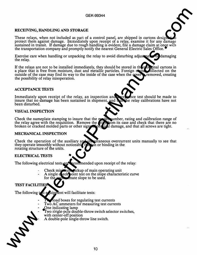
RECEMNG, HANDLING AND STORAGE
These relays, when not included as part of a control panel, an� shipped in cartons designed to protect them against damage. Immediately upon receipt of a relay, examine it for any damage sustained in transit. If damage due to rough handling is evident, file a damage claim at once with the transportation company and promptly notify the nearest General Electric Sales Office.
Exercise care when handling or unpacking the relay to avoid disturbing adjustments or damaging the relay.
If the relays are not to be installed immediately, they should be stored in their original cartons in a place that is free from moisture, dust and metallic particles. Foreign matter collected on the outside of the case may find its way to the inside of the case when the cover is removed, creating the possibility of relay misoperation.
ACCEPTANCE TESTS
Immediately upon receipt of the relay, an inspection and acc€:�ptance test should be made to insure that no damage has been sustained in shipment, and that the relay calibrations have not been disturbed.
VISUAL INSPECI'ION
Check the nameplate stamping to insure that the model number, rating and calibration range of the relay agree with the requisition. Remove the relay from its case and check that there are no broken or cracked molded parts or other signs of physical damage, and that all screws are tight.
MECHANICAL INSPECTION
Check the operation of the auxiliary and instantaneous overcurrent units manually to see that they operate smoothly without noticeable friction or binding in the rotating structure of the units.
ELECTRICAL TESTS
The following electrical tests are recommended upon receipt of the relay:
Check minimum pickup of main operating unit A single check point test on the slope characteristic curve for the approximate slope to be used.
TEST FACILITIES
The following test equipment will facilitate tests:
Two load boxes for regulating test currents Two AC ammeters for measuring test currents One indicating lamp Two single-pole double-throw switch selector switches, with center-off position A double-pole single-throw line switch.
10 www . El
ectric
alPar
tMan
uals
. com
www . El
ectric
alPar
tMan
uals
. com

GEK-99344
Check the picku� of the main unit using the connections shown in Figure 9. During this test, the selector switch S4) is open, and current passes through the differential circuit only. For example, on a re ay set w1th 25fercent slope and a 2.9 ampere ratio matching tap, the main unit should pick up at 30 percent o tap rating, plus or minus ten percent; or the pickup should be between 0.78 and 0.96 ampere. To check that the main unit has picked up, a source of DC power at rated voltage should be connected as shown in Figure 9. The indicating lamp will provide a signal showing that the main unit has operated.
For an additional pickup test, set the pickup at 1.5 amperes with current flowin_g in terminals 5 and 6, and place tlie tap plugs in the five ampere and 25 percent slope tap position. Since the NBD relay uses a polarized unit with a very low energy level, the mmimum pickup setting may vary as much as plus or minus ten percent. If the pickup is between 1.35 and 1.65 amperes, no adjustment should be made. Repeated pickup operations in succession erase the magnetic memory of previous tests, which may have affected the first tests. A severe through-fault will produce an effect which will increase the current required to pick up the relay. The pickup of the NBD relay has wider permissible variations than most protective relays, but due to the relay design and application, relay accuracy is entirely adequate under all conditions, even during severe fault conditions.
After the other tests are complete, check relay dropout with the selector switches(es) open. The purpose of this test is to insure that the polarized operating element will reset properly after a heavy internal fault current, which can leave excessive residual flux in its magnetic structure. Apply a current of 30 amperes to terminals 5 and 6 with tap plugs for all windings in the 2.9 ampere tap position, and tlie percent. slope tap plug in the 25 percent slope position. This will cause the auxiliary relay to pick up sharply. The current should then be reduced, rafidly at first, and then slowly until the auxiliary relay drops out. Dropout current should be 0. ampere or more. If dropout current is other than as specified, the polarized unit is defective, and should be replaced.
INSTALLATION PROCEDURE
TESTS
Before placing the relay in service, check the relay calibration that will be used to insure it is correct. The following test procedure is outlined for this purpose.
CAUTION: The relay calibration is accomplished by adjusting resistors Rl and R3. Changes made in either one of these resistors will affect the other resistor's settings. In the event one setting is changed, the pickup, and through-current restraint adjustment procedures should be repeated until no further deviation from proper calibration is noted. The best results are obtained when the through-current restraint adjustment is made after the other setting is correct.
PICKUP
The test circuit for pickup is as shown in Figure 10, with S2 open. Pickup should be 1.5 amperes with current flowing in terminals 5 and 6, and the tap plugs in the five ampere and 25 percent slope tap positions. The pickup operation should be repeated several times until two successive readings agree within. 0.01 ampere, with total pickup current being interrupted between successive checks.
1 1 www . El
ectric
alPar
tMan
uals
. com
www . El
ectric
alPar
tMan
uals
. com

GEK-99344
The pickup of the polarized unit varies slightly depending upon the history of its magnetic circuit. The repeated pickup operation restores the condition of tlie magnetic circuit to some reference level, thus eliminating any initial variation in magnetic history.
The condition of the magnetic circuit is influenced by the manner in which pickup current is removed after a test. For this reason, pickup readings will be slightly lower if the current in the differential circuit is reduced gradually, than If the current is abtuptly reduced or interrupted.
Since the NBD relays use a polarized unit with very low energy level, the minimum pickup may vary as much as plus or minus ten percent. If the pickup is found to be anywhere withm this range, 1.35-1.65 amperes, the setting should not be disturoed.
With DC control voltage applied to the proper studs of the relay, the pickup of the auxiliary unit can be used as an indication of operation of the polarized relay utnit. This voltage may be applied as shown in Figure 10, and the indicating lamp will indicate that the main unit has operated.
If the pickup is found to be out of adjustment, adjust the position of the band on resistor R1, which IS connected in parallel with the operating coil of the polarized unit. Resistor R1 is located at the top of the relay, and is the left-hand adjustable resistor (see Figure 2).
THROUGH-CURRENT RESTRAINT
The through-current restraint, which gives the relay the percentage differential or P.ercent slope characteristics shown in Figure 5, may be checked and adjusted using the circuit Illustrated in Figure 10, with S2 closed to position B. Ammeter I 1 reads the differential current, and I3 reads the smaller of the two through-currents. When testing NBD relays, the setting should be checked with switch S4 first in one position, and then the other, thus checking all the restraint coils. The relay should just pick up for the values of I 1 and I3 currents indicated in Table II, with the current tap plugs in the 5.0 ampere position, and tlie percent slope tap plug in the 40 percent position. Repeat with the percent slope tap plug in the 25 and 15 percent positions. If any one of these set pomts is not as prescribed, adjust the particular band on resistor R3 (located near the top of the case behind the nameplate) associatea with it, as indicated in Table II. Note that the current magnitude in the through- current branch (I3) is slightly influenced by the application of the differential current (I 1) and should be checked to insure that it is maintained at its proper value.
Any change in R3 to obtain the desired slope will have a small effect upon minimum pickup. However once the slope setting has been set, any adjustment of minimum pickup will change the slope characteristics. The slope set points must then be rechecked to msure that they are in accordance with Table II.
12 www . El
ectric
alPar
tMan
uals
. com
www . El
ectric
alPar
tMan
uals
. com
GEK-99344
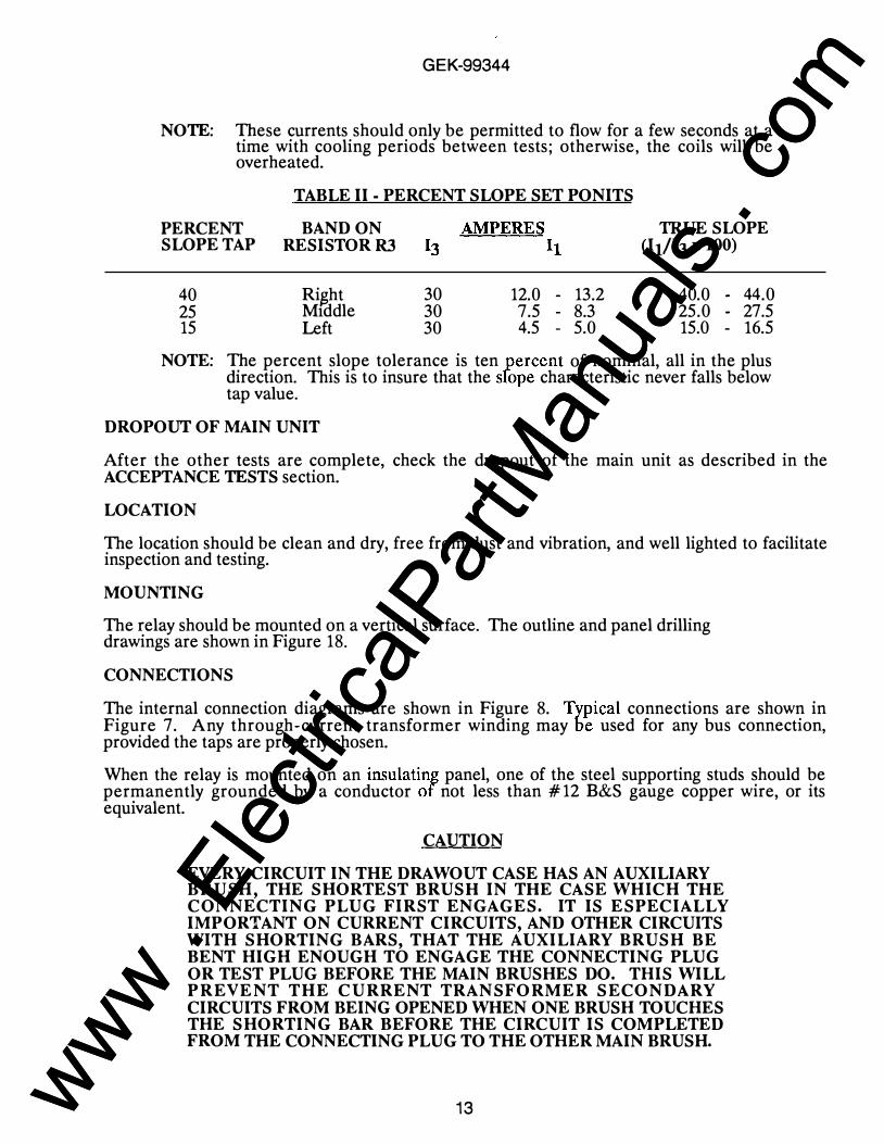
NOTE: These currents should only be permitted to flow for a few seconds at a time with cooling periods between tests; otherwise, the coils will be overheated.
TABLE II - PERCENT SLOPE SET PONITS
PERCENT BAND ON SLOPE TAP RESISTOR R3
40 Ri�ht 25 M1ddle 15 Left
30 12.0 - 13.2 30 7.5 - 8.3 30 4.5 - 5.0
TRUE SLOPE (l1/l3 X 100)
40.0 - 44.0 25.0 - 27.5 15.0 - 16.5
NOTE: The percent slope tolerance is ten percent of nominal, all in the plus direction. This is to insure that the sfope characteristic never falls below tap value.
DROPOUT OF MAIN UNIT
After the other tests are complete, check the dropout of the main unit as described in the ACCEPTANCE TESTS section.
LOCATION
The location should be clean and dry, free from dust and vibration, and well lighted to facilitate inspection and testing.
MOUNTING
The relay should be mounted on a vertical surface. The outline and panel drilling drawings are shown in Figure 18.
CONNECTIONS
The internal connection diagrams are shown in Figure 8. Typical connections are shown in Figure 7. Any through-current transformer winding may be used for any bus connection, provided the taps are properly chosen.
When the relay is mounted on an insulating panel, one of the steel supporting studs should be permanently grounded by a conductor of not less than # 12 B&S gauge copper wire, or its equivalent.
CAUTION
EVERY CIRCUIT IN THE DRAWOUT CASE HAS AN AUXILIARY BRUSH, THE SHORTEST BRUSH IN THE CASE WHICH THE CONNECTING PLUG FIRST ENGAGES. IT IS ESPECIALLY IMPORTANT ON CURRENT CIRCUITS, AND OTHER CIRCUITS WITH SHORTING BARS, THAT THE AUXILIARY BRUSH BE BENT HIGH ENOUGH TO ENGAGE THE CONNECTING PLUG OR TEST PLUG BEFORE THE MAIN BRUSHES DO. THIS WILL PREVENT THE CURRENT TRANSFORMER SECONDARY CIRCUITS FROM BEING OPENED WHEN ONE BRUSH TOUCHES THE SHORTING BAR BEFORE THE CIRCUIT IS COMPLETED FROM THE CONNECTING PLUG TO THE OTHER MAIN BRUSH.
13 www . El
ectric
alPar
tMan
uals
. com
www . El
ectric
alPar
tMan
uals
. com
GEK-99344
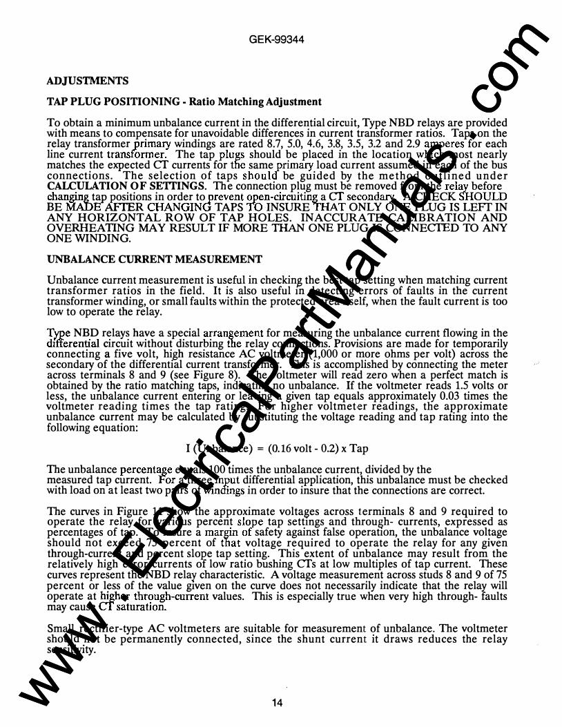
ADJUSTMENTS
TAP PLUG POSITIONING - Ratio Matching Adjustment
To obtain a minimum unbalance current in the differential circuit, Type NBD relays are provided with means to compensate for unavoidable differences in current transformer ratios. Taps on the relay transformer primary windings are rated 8.7, 5.0, 4.6, 3.8, 3.5, 3.2 and 2.9 amperes for each line current transformer. The tap plugs should be placed in the location which most nearly matches the expected CT currents for the same primary load current assumed in each of the bus connections. The selection of taps should be guided by the method outlined under CALCULATION OF SEITINGS. The connection plug must be removed from the relay before changing tap positions in order to prevent open-circuiting a cr secondary. A CHECK SHOULD BE MADE AFfER CHANGING TAPS TO INSURE THAT ONLY ONE PLUG IS LEFf IN ANY HORIZONTAL ROW OF TAP HOLES. INACCURATE CALIBRATION AND OVERHEATING MAY RESULT IF MORE THAN ONE PLUG IS CONNECTED TO ANY ONE WINDING.
UNBALANCE CURRENT MEASUREMENT
Unbalance current measurement is useful in checkin$ the best tap setting when matching current transformer ratios in the field. It is also useful m detecting errors of faults in the current transformer winding, or small faults within the protected area its,elf, when the fault current is too low to operate the relay.
Type NBD relays have a special arrangement for measuring the unbalance current flowing in the differential circuit without disturbing the relay connections. Provisions are made for temporarily connecting a five volt, high resistance AC voltmeter (1,000 or more ohms per volt) across the secondary of the differential current transformer. This is accomplished by connecting the meter across terminals 8 and 9 (see Figure 8). The voltmeter will read zero when a perfect match is obtained by the ratio matching taps, indicating no unbalance. If the voltmeter reads 1.5 volts or less, the unbalance current entenng or leaving a given tap equals approximately 0.03 times the voltmeter reading times the tap rating. For higher voltmet,er readings, tlie approximate unbalance current may be calculated by substituting the voltage reading and tap rating into the following equation:
I (Unbalance) = (0.16 volt - 0.2) x Tap
The unbalance percentage equals 100 times the unbalance current, divided by the measured tap current. For a three input differential application, this unbalance must be checked with load on at least two pairs of windings in order to insure that the connections are correct.
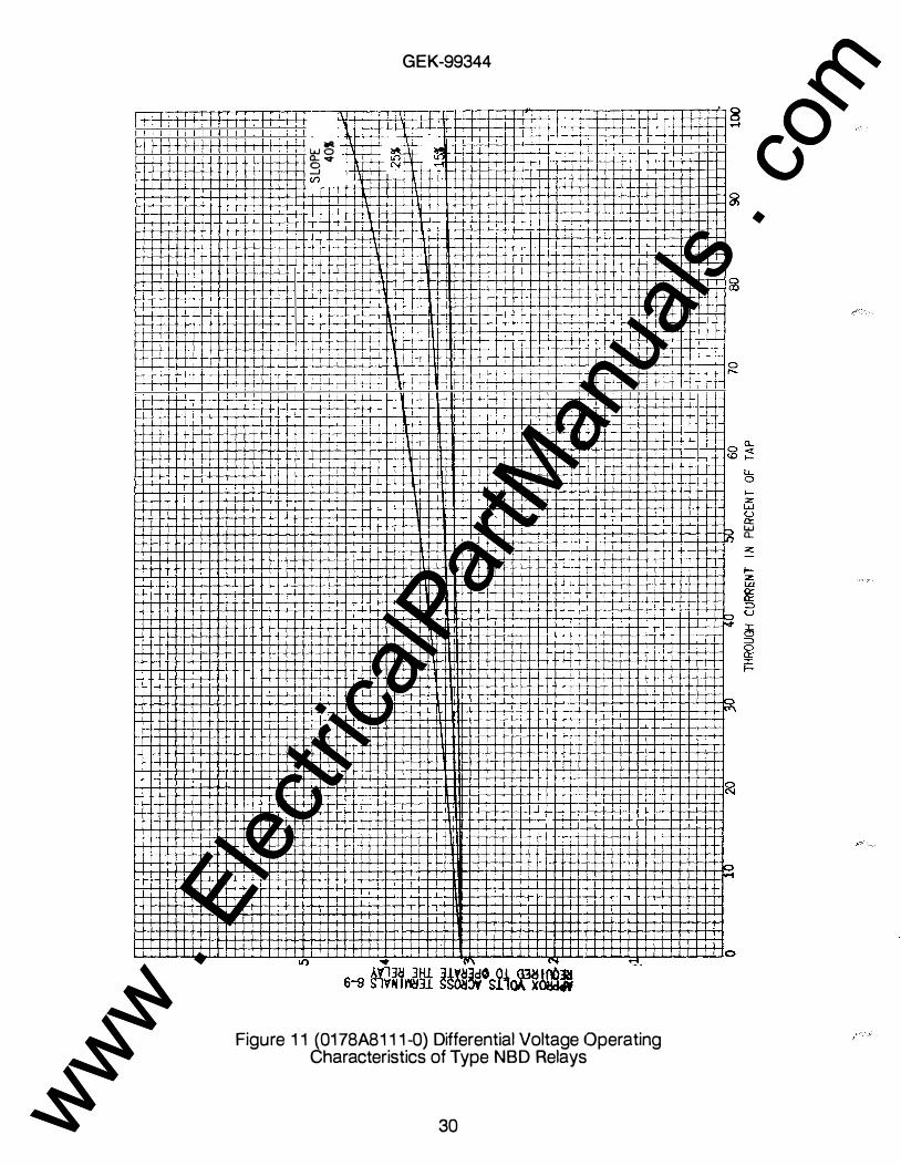
The curves in Figure 11 show the approximate voltages across terminals 8 and 9 required to operate the relay for various percent slope tap settmgs and throu&h- currents, expressed as percentages of tap. To insure a margin of safety against false operatiOn, the unbalance voltage should not exceed 75 percent of that voltage required to operate the relay for any given through-current and percent slo_Re tap setting. This extent of unbalance may result from the relatively high error currents of low ratio bushing CTs at low multiples of tap current. These curves represent the NBD relay characteristic. A voltage measurement across studs 8 and 9 of 75 percent or less of the value given on the curve does not necessarily indicate that the relay will operate at higher thr�mgh-current values. This is especially true when very high through- faults may cause CT saturatiOn.
Small rectifier-type AC voltmeters are suitable for measurement of unbalance. The voltmeter sho-ql� .not be permanently connected, since the shunt current it draws reduces the relay sensitiVIty.
14 www . El
ectric
alPar
tMan
uals
. com
www . El
ectric
alPar
tMan
uals
. com

GEK-99344
PERCENT SLOPE SETTING
Taps for 15, 25 and 40 percent slope settings are provided in the NBD 16A relay. It is common practice to use the 25 percent setting unless special connections make it advisable to use one of the others. See the l'ERCENT SLOPE SETTING heading in the CALCULATION OF SETTINGS section of this instruction book for further details.
CALCULATION OF SETTINGS
1. Check the matching of relay currents to relay taps to keep the mismatch error as low as possible.
2.
For three input differential applications, the percent of mismatch error should be checked for all combmations of currents or taps.
If taps cannot be selected to keep this error percentage within allowable limits, choose a different CT ratio at one or more breakers to obtain a better match between relay and currents and relay taps.
Check that the sum of relay currents that will be applied to the relay for the maximum fault is less than 220 amperes RMS for one second. If the period during which a fault current flows in the relay can definitely be limited to a shorter time, a higher current can be accommodated in accordance with the equation:
(Amperes)2 x seconds = 48,400
Also check that the sum of the multiples of tap current on an internal or external fault does not exceed 150.
CURRENT TRANSFORMER RATIO ERROR
The current transformer ratio error should be less than 20 percent at eight times relay rated tap current.
As far as CT performance is concerned, the calculations listed below are for the worst fault condition.
1. Determine the burden on each Cf, using the following expressions:
For wye-connected Cfs: z- B + Ne + 2·50f + 2.27R ohms - 1000
For delta-connected CTs
where:
Z - 2B + Ne + 2·50f + 2.27R ohms - 1000
B = NBD relay total burden (See Table III) N = number of turns in bushing CT e = bushing CT resistance per turn, milliohms f = bushing CT resistance per lead, milliohms R = one-way lead resistance (at maximum expected temperature)
15 www . El
ectric
alPar
tMan
uals
. com
www . El
ectric
alPar
tMan
uals
. com
GEK-99344
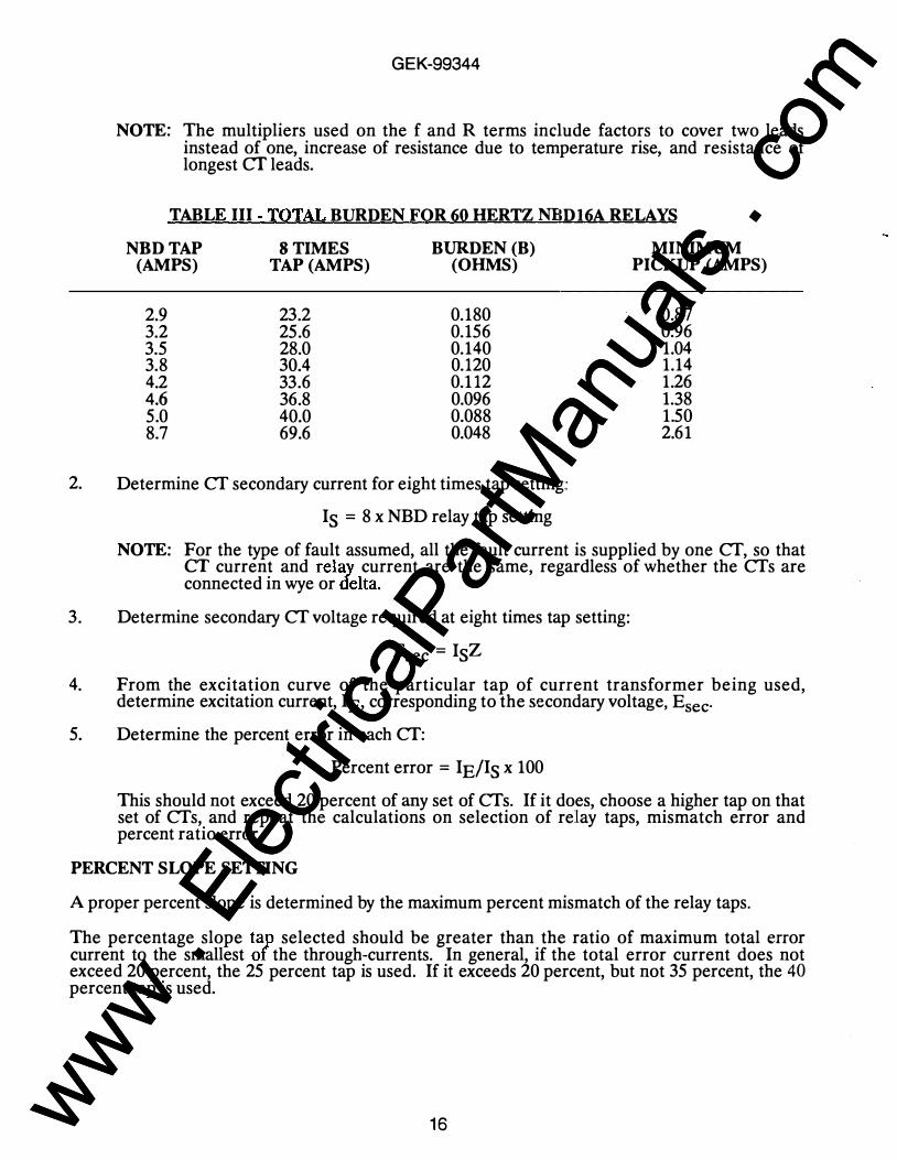
NOTE: The multipliers used on the f and R terms include factors to cover two leads instead of one, increase of resistance due to temperature rise, and resistance of longest cr leads.
TABLE III -TOTAL BURDEN FOR 60 HERTZ NUD16A RELAYS
NBD TAP STIMES BURDEN (B) (AMPS) TAP (AMPS) (OHMS)
2.9 23.2 0.180 3.2 25.6 0.156 3.5 28.0 0.140 3.8 30.4 0.120 4.2 33.6 0.112 4.6 36.8 0.096 5.0 40.0 0.088 8.7 69.6 0.048
2. Determine Cf secondary current for eight times tap setting::
Is = 8 x NBD relay tap setting
MINIMUM PICKUP (AMPS)
0.87 0.96 1.04 1.14 1.26 1.38 1.50 2.61
NOTE: For the type of fault assumed, all the fault current is supplied by one Cf, so that CT current and relay current are the same, regardless of whether the Cfs are connected in wye or delta.
3. Determine secondary Cf voltage required at eight times tap setting:
Esec = IsZ
4. From the excitation curve of the particular tap of current transformer being used, determine excitation current, IE, corresponding to the secondary voltage, Esec·
5. Determine the percent error in each Cf:
Percent error = IE/Is x 100
This should not exceed 20 percent of any set of Cfs. If it does, choose a higher tap on that set of Cfs, and repeat the calculations on selection of relay taps, mismatch error and percent ratio error.
PERCENT SLOPE SETTING
A proper percent slope is determined by the maximum percent mismatch of the relay taps.
The percentage slope tap selected should be greater than the ratio of maximum total error current to the smallest of the through-currents. In general, if the total error current does not exceed 20 percent, the 25 percent tap is used. If it exceeds 20 percent, but not 35 percent, the 40 percent tap is used.
16 www . El
ectric
alPar
tMan
uals
. com
www . El
ectric
alPar
tMan
uals
. com

OPERATING PRINCIPLES
TARGETS
GEK-99344
The auxiliary relay does not function as a seal-in since it does not carry breaker tripping current. After a fault is cleared, the target should be reset by the reset slide, located at the lower left hand corner of the relay.
DISABLING TYPE NBD RELAYS
When bypassing a breaker during maintenance, the NBD relay must be disabled to prevent false tripping. If disabling is done by a remote switch rather than by removal of the relay connection plug, the following precautions must be taken:
Short circuit studs 8 and 9 of the relay, or open the trip circuit at stud 1. The trip circuit should be opened at stud 1 because the series resistors in the auxiliary relay circuit cannot withstand contmuously rated control voltage, in the event that the polarized relay operates.
If the Cf secondaries are short-circuited as part of the disabling procedure, the trip circuit should be opened at stud 1, and studs 8 and 9 should be short-circuited before the Cf secondaries are short-circuited. Do not rely on short-circuiting the Cf secondaries only, because any difference in shorting time may cause false tripping.
MAINTENANCE
CONTACT CLEANING
A flexible burnishing tool should be used for cleanin& fine silver contacts. This is a flexible strip of metal with an etched-roughened surface, which m effect resembles a superfine file. The polishing action of this file is so delicate that no scratches are left on the contacts, yet it cleans off any corrosion thoroughly and rapidly. The flexibility of the tool insures the cleaning of the actual pomts of contact.
Fine silver contacts should not be cleaned with knives, files, or abrasive paper or cloth. Knives or files may leave scratches which increase arcing and deterioration of the contacts. Abrasive paper or cloth may leave minute particles of insulating abrasive material in the contacts and thus prevent closmg.
The burnishing tool described above can be obtained from the factory.
PERIODIC CHECKS AND ROUTINE MAINTENANCE
An operation test and inspection of the relay and its connections should be made at least once every six months. Tests may be performed as described in INSTALLATION TESTS, or they made be made on the service taps as described in this section.
When inserting or withdrawing a U-shaped test plug through-jumper to complete the trip circuit through the test plug, similar through-jumpers should also be used on studs 8 and 9 to maintain the connections from the relay to tlie case. If not, false tripping upon insertion or removal of the test plug may occur.
17 www . El
ectric
alPar
tMan
uals
. com
www . El
ectric
alPar
tMan
uals
. com
GEK-99344
PICKUP
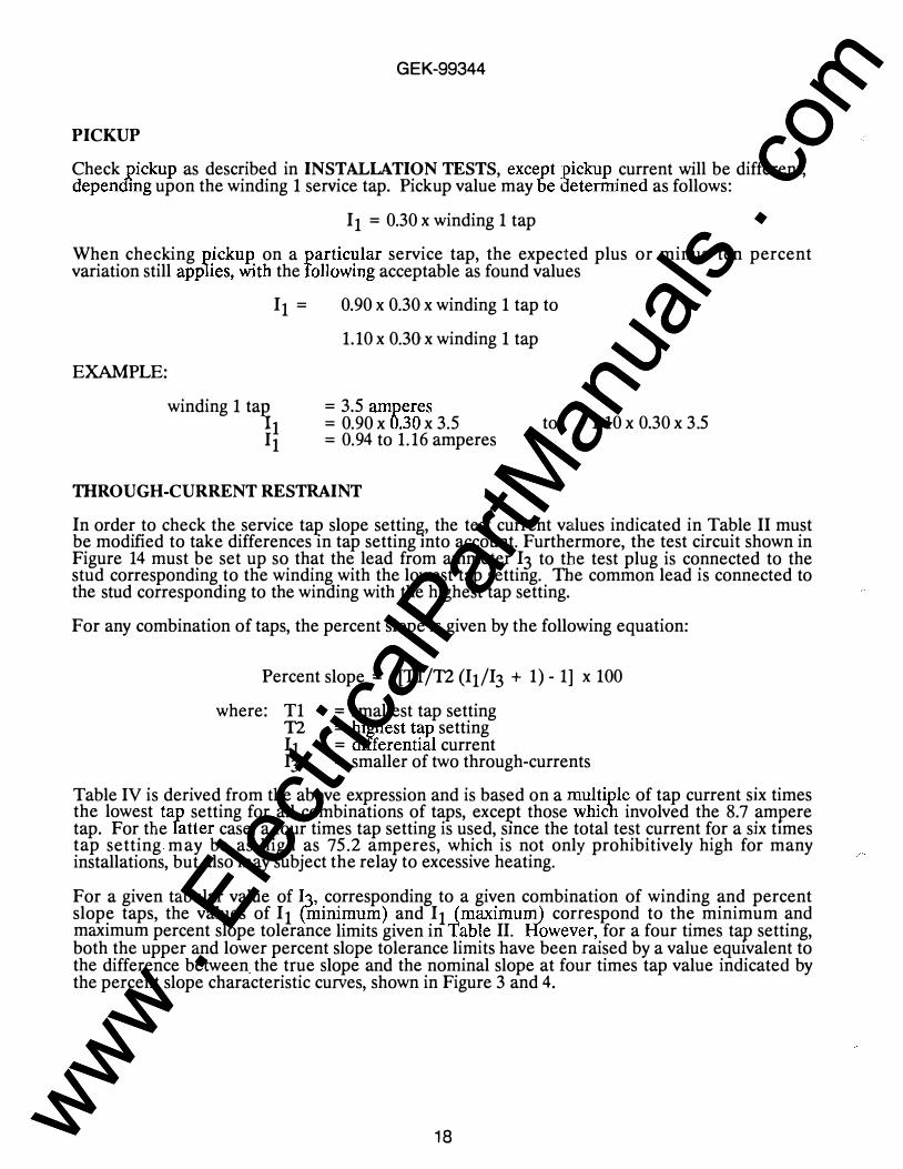
Check pickup as described in INSTALLATION TESTS, except pickup current will be different, depending upon the winding 1 service tap. Pickup value may be lktermined as follows:
I 1 = 0.30 x winding 1 tap
When checking pickup on a particular service tap, the expected plus or minus ten percent variation still app1ies, with the following acceptable as found values
EXAMPLE:
I 1 = 0.90 x 0.30 x winding 1 tap to
1.10 x 0.30 x winding 1 tap
= 3.5 amperes winding 1 ta� I � = 0.90 X 0.30 X 3.5
= 0.94 to 1.16 amperes to
THROUGH-CURRENT RESTRAINT
1.10 X 0.30 X 3 .5
In order to check the service tap slope setting, the test current values indicated in Table II must be modified to take differences in tap setting mto account. Furthermore, the test circuit shown in Figure 14 must be set up so that the lead from ammeter I 3 to the test plug is connected to the stud corresponding to the winding with the lowest tap setting. The common lead is connected to the stud corresponding to the winding with the highest tap setting.
For any combination of taps, the percent slope is given by the following equation:
Percent slope = [T1/T2 (I1/I3 + 1) - 1] x 100
where: T1 = smallest tap setting T2 = highest tap setting I 1 = differential current I3 = smaller of two through-currents
Table IV is derived from the above expression and is based on a multiple of tap current six times the lowest tap setting for all combinations of taps, exceJ?t those which involved the 8.7 ampere tap. For the latter case, a four times tap setting is used, smce the total test current for a six times tap setting may be as high as 75.2 amperes, which is not only prohibitively high for many installations, but also may subject the relay to excessive heating.
For a given tabular value of I3, corresponding to a given combination of winding and percent slope taps, the values of I1 �minimum) and I1 (maximum) correspond to the minimum and maximum percent slope tolerance limits given in Table II. However, for a four times tap setting, both the upper and lower percent slope tolerance limits have been raised by a value eqmvalent to the difference between. the true slope and the nominal slope at four times tap value indicated by the percent slope characteristic curves, shown in Figure 3 and 4.
18 www . El
ectric
alPar
tMan
uals
. com
www . El
ectric
alPar
tMan
uals
. com

EXAMPLE:
Winding 1 tap Winding 2 tap Slope tap
= 3.5 amperes = 5.0 amperes = 40 percent
GEK-99344
Since winding 1 has the lower tap setting, the lead from ammeter l3 to the test plug should be connected to stud 6, and the common lead should be connected to stua 4.
From Table IV: 13
����!� = 2 1.0 amperes = 21.0 amperes = 22.2 amperes
19 www . El
ectric
alPar
tMan
uals
. com
www . El
ectric
alPar
tMan
uals
. com

1\) 0
TABLE IV- TIIROUGH CURRENT RESTRAINT TEST SETTINGS
- -, - - - -- - - - I -- - - -- --,- ---- - - T ITAPSI T2 I 2.9 I 3.2 I 3.5 I 3.8 I 4.2 I 4.6 I 5.0 I 8.7 I 1r1 1� 1 15 25 40 I 15 25 40 1 15 25 4o 1 15 25 40 I 15 25 4o 1 15 25 40 1 15 25 40 1 15 25 40 1 I I Cur rent I I I I I I I I I
1 113 117.4 17.4 17.4117.4 17.4 17.4117.4 17.4 17.4j17.4 17.4 17.4117.4 17.4 17.4117.4 17.4 17.4117.4 17.4 17.4111.6 11.6 11.61 12.9 II1cmin) 1 2.6 4.3 7.01 4.6 6.6 9.51 6.7 8.8 12.01 8.8 11.1 14.5111.6 14.1 17.9114.3 17.1 21.2117.1 20.1 24.6128.7 32.2 37.41 1 II1cmax> I 2.9 4.8 7.71 5.0 7.1 10.31 7.1 9.4 12.81 9.2 11.7 15.4112.0 14.8 18.9114.8 17.8 22.4117.6 20.9 25.8129.3 33.1 38.91
1 113 1 119.2 19.2 19.2119.2 19.2 19.2119.2 19.2 19.2j19.2 19.2 19.2119.2 19.2 19.2j19.2 19.2 19.2112.8 12.8 12.81 13.2 II1cmin) I I 2.9 4.8 7.71 4.9 7.0 10.21 7.0 9.3 12.71 9.8 12.3 16.1112.5 15.3 19.4115.3 18.3 22.8127.5 31.0 36.21 I II1cmax) I I 3.2 5.3 8.51 5.3 7.6 11.01 7.4 9.9 13.6110.2 13.0 17.1113.0 16.0 20.6115.8 19.1 24.0128.1 31.9 37.71
1 113 1 1 121.0 21.0 21.0121.0 21.0 21.0121.0 21.0 21.0121.0 21.0 21.0121.0 21.0 21.o114.o 14.o 14.ol 13.5 II1cmin) I I I 3.1 5.2 8.41 5.2 7.5 10.91 8.0 10.5 14.3110.7 13.5 17.6113.5 16.5 21.0126.3 29.8 35.01 1 111cmax> 1 1 1 3.5 5.8 9.31 5.6 8.1 11.81 8.4 11.2 15.3111.2 14.2 18.8l14.o 17.3 22.2126.9 30.7 36.51
I 113 I 1 1 122.8 22.8 22.8122.8 22.8 22.8122.8 22.8 22.8122.8 22.8 22.8115.2 15.2 15.21 13.8 111cmin> 1 1 1 1 3.4 5.7 9.11 6.2 8.7 12.51 8.9 11.1 15.8111.7 14.7 19.2125.1 28.6 33.81 1 111cmax> 1 1 1 1 3.8 6.3 1o.o1 6.6 9.4 13.51 9.4 12.4 11.0112.2 15.5 20.4125.7 29.5 35.31
I 113 I I 1 1 125.2 25.2 25.2125.2 25.2 25.2125.2 25.2 25.2116.8 16.8 16.81 14.2 II1cmin> 1 1 1 I I 3.8 6.3 10.11 6.5 9.3 13.41 9.3 12.3 16.8123.5 27.o 32.21 1 jl1cmax> 1 1 1 1 1 4.2 7.o 11.11 7.o 1o.o 14.61 9.8 13.1 18.0124.1 27.9 33.71
I I I I I I I I 127 6 "'7 f. ")7 /I..J77 I. ')"7 I. ., ... L I 1 n • • ft • o- • 0 3 . , • _ c.. ·- -· ·-r�· .w .. , .u '' .ol o.'t IO.'t J0.4j
!4.6 ! I ;<min) I I j I I I 4.1 6.9 11.01 6.9 9.9 14.4121.9 25.4 30.61 1 111cmax> 1 1 1 1 1 1 4.6 7.6 12.21 7.4 10.1 15.6122.5 26.3 32.11
I 1'3 I I I 1 I 1 l3o.o 3o.o 3o.o12o.o 2o.o 20.01 1s.o II1cmin> I I I I I I I 4.5 7.5 12.0120.3 23.8 29.01 1 111cmax> 1 I 1 1 I 1 1 5.o 8.3 13.2120.9 24.7 30.51
I 1'3 I I I I I 1 1 134.8 34.8 34.81 18.7 II1cmin) I I I I I I I I 5.5 9.0 14.21 1 111cmax> 1 1 1 1 1 1 1 1 6.1 9.9 15.71
G) m � CD 1\) � �
www . El
ectric
alPar
tMan
uals
. com
www . El
ectric
alPar
tMan
uals
. com

GEK-99344
RENEWAL PARTS
Sufficient quantities of renewal parts should be kept in stock for the prompt replacement of any that are worn, broken or damaged.
When ordering renewal parts, address the nearest Sales Office of the General Electric Company. Specify the name of the part wanted, quantity required, and complete nameplate data, including the serial number, of the relay. ·
Since the last edition, Figures 3 and 4 have been changed.
21 www . El
ectric
alPar
tMan
uals
. com
www . El
ectric
alPar
tMan
uals
. com

GEK-99344
RATIO
TAPS
SERIES TUNING
--CA,PACITOR
((� 11)
DIFFERENTIAL
'i-i-·---CURRENT
TRANSFORMER (DCT)
Figure 1 (891 9350) Type NBD Relay, Out of CasE3, Front Right View
SERIES
TUN IN
INDUCTOR
(Ll)
Figure 2 (891 9351) Type NBD Relay, Out of Case!, Rear Left View
22 www . El
ectric
alPar
tMan
uals
. com
www . El
ectric
alPar
tMan
uals
. com

� g (/) 1--
80
7 0
6 0 .
50
4 0
�3 u 0 Q: � � 2
'n �2 :2
1 ()
0
\ l
\
\ \ �
\ \ \ \.
\ ."
\ '
0 2
GEK-99344
NOTE: FOR TWO WINDING RELAYS "THROUGH CURRENT" IS TAKEN AS THE SMALLER
OF THE TWO CURRENTS. FOR THREE WINDING RELAYS, IT IS TAKEN AS THE SUM OF THE INCOMING OR OUTGOING CURRENTS, WHICHEVER IS SMALLER. EACH CURRENT TO BE EXPRESSED AS A
MULTIPLE OF A TAP.
............ 4()1: .
""'"' .....__ 251.
........._ ...... 151
4 6 8 10 12 ntROOGH QJRRENT II t.tULTI PLES OF TAP
Figure 3 (0285A5494) Operating Characteristics of the Type NBD Relay
23
--
14 16
www . El
ectric
alPar
tMan
uals
. com
www . El
ectric
alPar
tMan
uals
. com
1\) �
100 �r -� :···r= ··· - · · ·· · :rj "'�ffi'[ffil' · r n "T' ']If IT Tf fT ' i j r 1 i 1 ! : : 1 : : ! I ; i ' i : : j : : ' i ' i , I i i 1 ' I 1 1 I � · ' : j l i 1 1 1 I I ! I jl ! 1 · ' • 1 · l j i l' l l l' !�· l ! i ' / ' I. Willi I , , / . , j l l l l l ' 1 / , 1 1 : j : 1 1 ] 1 . 1 1 ! . j . " : : J l. ! / 1 1 1 , l i : •. l l h !, l. \1 ! ! I L. ;.; . . . . : . 1 ! . i l l j Ill I I I j l I t : i : : : , ! , i l ' · : ; : I 1 ; : : , , . . · ' ' : :: . 1 ! '1: : 1 ; ::....F . . .. u ::, . . . :. : . . . . . ::.. - - -+-- - · . ... ··- -�: •·· _:., - . . . . I NBD16A ( - ) A : ' : . : . :
. . ' ' : ' I � . . ' . . i : • . . ' I • • . • · - · . . . . . ' . ' . . . ' ' " I : I , . I OPERATING CHARACTORI STICS
· · , ' . ' ' . ' I , 1 1 1 ' ' I J d ) : I J THROUGH CURRENT VS . PERCENT SLOPE 90 f.,-r--,- - . ·-r-�· ··- ·-· · : · · . . . . . , . . . . . . . . . . . . I • , : . . . . ' I . , . . ' I l l , , . , , , . . . . , . , , , , , ' t ' : 'I ' ' I I j ' ' I , " ' I ' · , i ; , , J l • / l r r l' j i l l l i l r I 1 / j ' j / 1 , I ' . 1 . . I " ' . . : • J . ' I I . . . : 1 : I i ' '" J . , ' I ' r l " ' " · I , , :
,. I I ' , ' / i i i , I i i ' d ; J i r JJ J : · : :1 r :j 1 : ! l_ l M!+ .:!: ; 1 • · , . �! .J ' :;� .r:: ! 1 ;! ul! . I� (� NOTE : FOR THREE WINDING DI FFERENTIAL � : 1 1 : r ' ' ' " 1 ' 1 ! ' 1 1 : 1 ! , , 1 '17;f : · , . � f ' i ' ! ' -�rm; J r ; ) r / 1 Dr J,, �I ' q r , ,, : : RELAY S , THROUGH CURRENT IS TAKEN � .i \ 1H· 'n�ll, " 1 1 . . . . . . . . 1, , . II , . . , , , 1 , � � , , 1 • • • , . , . , • 1 As THE sUM OF THE I NCOMING OR 11 1 l : i J I' l I l r : ! . l i j J ' i · ' ( 1 . 1 , 1 ' 1 i ' r ! 1 , , ! r : ' ' 1 ' 1 1 1 1 1 1 1 ' I I' 1 I ' i / 1 ' 80 '�d 1L ' II • · · ' 1 1 " ' 1 · I · ' 1 ' ' ' ' ' 1 1 ' ' j f 1 1 · 1 ' ' I
OUTGOING CURRENTS WHICHEVER I S i l l 1 /! " . I , , I ' I I , I I ' , 1 ' ' ·-· · : · · i� r;t , · ' . i i , l ·�: 1· :, , I ! 11 1 1 " · ' ' ' ' 1 1 1 1 I I ' 1 · 1 1 1 1 , I r l l , · , · ' I , , , , I I J:l j t+' iH; 1j: lllil llil J/: ). 1) 1 · : . i l l . . . . 1 . . . . . , , . : . , l ' i l . 1 . w). . J , j / J j i /' 1 1 . I ' SMALLER . EACH CURRENT TO BE CO I !J/ q : . I / : fiT 1 1 , , : : : : r 1 \ , ' , , . ' ' ' , : · , · : ! ' J I I ! 1 · 1 • I , : ; ; [ EXPRESSED AS A MULTIPLE OF A TAP . e M 1 1 , , , . , j , · 1 ' 1 1 1 , , . , . �t;- 7'f.-7""'f1� -·: :rl ' l jT , ; ·:n ·t · ; : : · .... I ! I j ! I : I J I j ll ' ! : I ' ! . . ! � ' � ; ! : ; . . I . I ' j . . I. ' : ' . . • : : : I ; • ' . I I . ' : ; ' I ! : ' I i ' : I CD / : J ' l r, ! Uj • 1 : ' 1 1 : J , . 1 ; , : l • , , , 1 r • 1 r l , 1 ' 1 1 j l l l j l , J i l l j / ! ' • I 1 • l it! · • • 1 fl ll jl!ll 1 1 1 fl • ' " 1 " ' ' " ' r r • l ' " tlJ l. 1.1 1 ' .l , fti" · � N :PI ' ;i : ! J . \ 1 · r l · i l , , • • : l : j : 1 , , . : . · ' _l! ' i l ' f8i tt4 t l ' . n l+lw·
�
� -t- _ __ _ , _ � nOMI I"' � L s L·o ,..t . 0 I
70 ; I I l! ' :\ : : 1 ' i I ' I ' l : l l ! t iJ ! : ! : � ! ! : : J : ! : ! ! l i � ! } ! : !0 : : , ; i ' I I : . � I ! I l l . ... ' . f . � lm1 ��" . . . _r- ��� �.ET J!G� li" l ,h ! ' : ' 1 � � M I I i I r l I h\ , . J ! I , ! Jill ' ! ' i: I ' I ' 1 : • , . , , �r ! , ' I n ]:' : � :, , · 1 1 , , 1 ! 1 ' 1[ Hli ' il. I ! Tr . ! ! 1 , , ; 1 ' l i ' ! ' ' ! , r $d�lt)jj ' ' I I i l l : , : : : il ' r ' ' I :;; , rj, : i ilirrll�� I I r: Htl r:k� � � � llg) � ; , : : J li ' I L�IW.. , L ��! i l l !� : ! 1 1 ) ! ! : , ! l i · I : , ' : ! ' % JTI1 !TI'I i ! l ! ;l i l i l j' i l l ' l i 1, 1 1 ! t l j l ! ' ! i' ' l ' l l l ' l' l l, l l� l ! ! i I m: :, l jl u', 1' r i 1 i l l i
'l ; i l l ' t l r I l l ! l i j i l j'l i Fjl i l l l i !r·' l ! l ! i l l ( i l l ; , 1 4 l !li ::i : ; . · · :
a. U1 � � � � . '"J' I ' · �� · , lUll . ' lU:��� � . , ' I.S ��� .; :. l1: ! ) I UJi ' j ' j. J ! !i ! ! . I , : ! I ! ! 4 t !lt . : I Wr� .ui ;.J; lg: . . . . ' ! I , I . • ' ' � · · · I I " ' ' ' , . 1+-1 . ' · � � � 60 ! JU ; lj j !L l l � 1 : . ! j l� 1 1 1 d j ! l! i: ; \ � � � �1 iJ I : J ! : . ' ' , · , . , i : , � : ' � i l l : I ! I j l l [ l l ! ' I ' t ! l l l j : t 1 l' i ! ! : � , ' ' ; j t i ; : i ilt 1 l i i ' i : 1 1 ·1 ! i : : � f ! ! i J , , ,,' i ; i 'i i , i : j : ; l i ; i l 'r l �jl i ! l i l r l l d l ! i l ! j f\l� ffi o.£! R !J ill 1 1 J i l l l t 1 ! , 1\ 1 ! 1 \ � : 1 ' , , ) : [. 1 · � : , ' 1 · 1 Jl: 1 1 r ' . , : I I I I : 1 ' · d i , 1 j ' l l\ 11 ! l j ml r ; : j I I : ; 1 \ 1 ' I : ' ' I ii[ llil 1 · 1 j�ut) ' , I ill! ' I ! 1 1 1 / !ll till! 441;:: 1 1 I 1 ( ! , ' . A �� c ! l jl l J!l ll! l ',· / I I��Nr�. , , �',;�� i:h : lr
· :�fii ' ! ! !�� ]! rl·� ; : :; �i L r
i 0 1 : ; , ! ! J i \ : t i l l : : : i : : ! I : : i i i l ilil i] j i �� �n : : :;: r , :; mi l l l i :1+1 ! ( i : i ll , : ill t ; ' / ! , f; ', : 1 : l l 'j l : ', i ll : i l l 1ill! i ; l lu!!li : i i · �f cO (6 CD E , , 1 J , J1i , ' lhL\ ' , , ' i' I I I I ' . ' , ' I ' ! ' ' I : , 1 ! ' , r ! I ' ' , 1 " r ' , . , : I" ' I r : : ; , I I ' : J I I I , , , r ' i I I I 1 ' 1 ' : 1, 1 ,�. , 1 1 tW I l , i l� : ' , 1 , , 1 , , • ' ' • .1 ' I WI i l l i I J ' Iii! < I ' , ' 1 ' ffi 0 � N 50 ' I J III J I I I Jl l l l l l
1 ·, li; rr,� -��" . . .. ? �: ;;r; · ; : ; ��: : i ,l l tt, : ;{ : ; : , : : ' : j l ' i l i' l : n; ; Til �·; : , : i i i�l i71 'j i. l"t ; , i i it f7i: l ]ttl l i ' 'i J i t' ' , Jl:tl\::[rtl l.l i l ! i r, , , :l� , " ' � : : . 1 11 1, : i l l , ' I : � � 'tHI ! r r lj!i�l l 'fi ll' � .... T I 1 11 / !+H • l i . 'ti ' I . ' ' , I I ::"� " h ' I I . ' ' ' • • . I I I I ' , , . ' I I " I ' ' 1 ' : 1 I . I. . . I . . I I , , , " I ' , . ' I ' . , . ' tk ' . , h-1 , , � ::;: §"· I ! I J : i l j I I ; ui j l\ I I ' , , I , : : r I �t'- : · I · , I I ' , , , ' I I , , , , l l r 1 , 1 I I J' j ' f ; 1 1 ! 1' I ! ' ! : I I WJI ; / , 1 ' '11 : : . · , , · , ' : 1 · i i i , · , ! , i l r l ! ' ' : I l;! / 1 j ! ' . I I ! l J I , I ! • ! : J . I I : , , , , I 'co s ll -� . . . . -'� . . . . . . . ... �1"-'o�.::...- -·· .. . . . .. . - · ' . . . . . . . , . . . . , , 'I ' "I J l .1 • • M ·� - �� � � th•r.;r - - · :1 · ll ' tO ' 1 : , , ; i / i l l / ; i l ' 1 · i : , · • 1 · r ' ' 1 ' ' · ' 1 1 7'�1-- · r l 1 1 I ' 1 : · ' ! ' , , l , l l I 1 1 1 ! : , · · I ' ' I ' 1 ' ' 1 , : 1 · r : : · : , ; • ' ' • r i i l I , : . 1 ; , : , ' ' / ' i ! ! : ' I ' I : , , 1 , c ,-.. L ! j l l l l l : I · ! · 1 / , , 1 1 1 . �� . : , , 1 • I , : ,, . . , L i l l i , , , , I f 1 1 ' , / 1 . . . r l i ' . . , J ·
l il' ' ' : I I : . . 1 . . . , . . , · I • . , , . . , 1 , . . . . , , ' J · I j ! l ' 1 j, l , j , · ; : · . . . .
-. \. I ' : ! 1 , I ' I I " I t\ , "' ' ' l j r ' I ' ' , , . , ' ' I ' , " I I ' I ' " ' I ' ' I , , 1 ' I ' , il r l : . , 1 . : . CD ::,- o 40 " " , , , . , . , , . ' ' I ' . _ , , : : 'o.;.;.;; ·'��� t.:...hn;...; : , � . , , l � _ , , , ' " ! IITr" ' !tm lrnf':'.; �-�:�� ·- fmtt·•-Hnl�t+� 1-"14�· . . · 'I , , . m I ; t I . ' I ! I , � t --;-� 1 , t : ; I , 1 I I ! t r 1 d : . , t � d q ·, q , tnr l I r I l l � ! � I I 1 1 ' ' ' I I I : r ' q 1 1 ' : 1 I ! 1 1 ' : ' r 1 1 I I I I I l l · � . r 1 1 1 I . 1 : w m p , 1 ! 1 illl l !H . ! I I ! 1 ) 1 1 J j , lf\ �I\.· , � : , . 1 . ! " ! ' : · · 1 , 1 1 : ! 1 : , ' I I ' r l / ' ! 1 1 1 lm , , 1 1 i d i ,mrn,, · ' ' : � , J l ! J i l , : l l , l l i l ! , 1 ! ! , , , 1 1 1 , 1 ,lrm , : 1 1 � , ! ) l ! i l l i , l , � ! , ' : ' : . . . : ' : : ' · ' ' · ·�, IL / ,1 , � · 1 : , 1 1 ; 1 : ! " : , r () E g; , , I Lll� � � 1 , J.\ , l j� , , , . , I . , , � � � � 1 . . , . . , , , 1 / , , . , , , , 1 , 1 , � , I I ' ' , , l i ' l , . , . · ' , . . : 1 , . 1 1 . . H , . . . , ,t . 'UJ ;� ' I ' . 'mi!WJ I I J / / , , 1 , ' : 1 . . . 4, , 4 1 1 , , J.W .u.w �� : . 1� , , .
m • l : · , , ;l " i' i ; , 1' ' ; , ;·,. t, . · �rl·:�,.; , ; � ;��� · : i ; : .,i i i i i i ! ' ' '! : ; ; : : · r : : ri� i ; ! i i i �, ; I I i 'i : : P ,'Ij: jjf ! i t; ·1 ! 1 ! 1 '1 ·,, ; : i j li l·; : j l , ] j l:ti il l , ,m hi j r1 · / i ll I :tt; 1 ! : : ! ! l] lfj iL l !',:i �j; ! ti l i :� j I i l !!' jl j l ! i j 1 i ! : t:T .... . . . , 1 1 1 ' : i l . 1 ' 1 ' ' I ' 1 1 !:\ . ' " / ; .' " ' " I I ' , . I ' , . 1 · I " ' I ! ' ! " ' ' l l , ' I , , , I ' : . , . . . ! . " I " j ' ' I q· I . , I ' " 1 . . , I I ' ' " ' I I · ' ' I . . 1 . ' " ' . · I · l t l . . : · 1 . . . (i)" d i , ; i l !1 l i j 1 ; : 1 : • I ' ; f : ' · : r ' i l l�� : , i l ; · d I I ! ' l r : l l l / 1 · j ' j · ! I 1 , 1 1 : j : I 1 / 1 1
1 1 . ' i i j J r , , i ' • 1 i , 1 1 1 1 / L r !� ' J I / · ' : · ;ill i ' r · 1 1 ; : " : 1 1 ; : ! i ! ! ! ! i i ! ! . . i i 1 1 g- 30 :ftj l !' l j J' l l"�i 1�! �,' l l i l l j1 1J i�J r�1 ; : t i 1 : ,·: j i i ,·7"'1 ! ��,:2i , ; l i : 1 1 1 i ! , 1 ! � . : 1 1 1 1 il !I I i i ) i i � � �� ; �ijf � f l , : ·,. -r ;! i l tl, l : r: : : l : r rn; ITi; 1, , r : ; : i i !i 1 ' 1 : :Ti' Ti H� [fl' i I J I I i l d I ! ! IJTfi I[! en 1 1 1 1 I ' j I I· . 1 / , 1 • ·1 ' . . I ' ' . , ,� , , 1 , I ' ' I ' ' : , , : .; 1:-" ' I ' . . ' ' : ' , I " ' ' . . " " J ' ' l , . . . ' , , " ' 1 1 1 1 I , , ' I · l · r " ' . . 1 , I I ' . . : : • · . . ' · ' , ' : 1 ' " I ' ' I ' l l I ' ' I , , ""- · ' I I I ' I I I ! I ' I I I I I I I ' ' ' , , , ' I ' I l l ' I J • ' J 'j / • 1 1 1 / l i 1 1 1 / l I ' ' ! [ : , , / ""' ' , 'j I • i p; r , i ! 1 , ' 1 Jj l 1 l 1 ' I 'll I 1 ' ' • , ' 1 ' ' 1 ' r ' I I ' , I ' : 1 1 '
! i i l l il j l I !' 1 ! 1 1 i I I i i L !�J -:-r, i l i W!�IIHrmt1i1� 1? • i l ! i l l l ! i l l ! 11 11 11 1j l 1 1nl il ll l l ' ' !! fl ! : 1 "l \ [I I �11 1' l j I IITI I I j ! ! ! I' 1 / 1, 1 1 ;T! I J il l : : ; ! m: : : ! , i i1 i ' 1 1 1 / 1 1 !, f 1 ' ! , , fi l i i[! . li l ' d� : I W: I i l l ' , , . ! i i i HI u� Ull�u�� ' I l ' i : : ' 1 H I , . 1 1 I lu I I ill 1 1 1 1 ' I " ' tW ! r l I 1 1 • : l i !l I I ( J ! i , , , 2 0 ! ' il ! ! ! , I I i :! I , , ! i i l : . . i . ! !! iljl !!!I IIli 1 ! : ! ' i i : l ! l ! ! m; ) ! i :7J;jr:m��· rtl n��� � r r ' l i l t ! , ' ,
, I I ! ! I : !: ' . � 1 [ 1 . l i / 1 , , 1 : ! [ ; , 1 ! ! 1 1 , : I ! I� �, :i ; l ) ! ! i l J I/ ! f : ! ! l il j : 1 ' ! 1 1 1 ! ! l l ! h ��?,�:! 1 I I d l · 1 1 1 · , ! , , : J i 1 1 1 I ' I J • ; r , , ' · / , r 1 1 ·� ll i� l l / .� • r ' j 1 1 l il ] I J ; ' I �flJ*IIi: ' ' ' 1 ' , r ' : : : • 1 ' , , . , I I ' ' ' !I , , , 1 ! 1 1 : , :: i l l l i r r , 'J4 I � t l ; l i l l I " II j l ! I I ) 1 ! 1 / i / 1 . ' i i : · , . l l t l l l / 1 1 1 : : . , , ir:i , i ' :� l :PIJ ! ' I i j i l l m ! ' � � l � r l f ! 1 1 i 1 I ITfr I I , J J I l l " ! llj!' l ' l i , : 1 ! ' i i i :
to �!;iJ j utlillw�1H � ;p , liu UJl iLJu i� : i l ! ll iJ i ltJ l ; I J i : i l ! ! i J l l i ! i 111· ' � � : 111 : l� �)l llllillli ill' 1 1 1 1 1 " : l l lii ' 'U 't!llill�liliiil!ii l iilJ IJU 1 ! / 'li�uwJJJhlll ''" l lllllllillllllulllilllill l 3 4 5
TH ROUGH C U R RE NT I N M U L T I P L E S Of' TA P
www . El
ectric
alPar
tMan
uals
. com
www . El
ectric
alPar
tMan
uals
. com
� >-� � u � z � = = � u � � ....c � < \C � Q = z
GEK-99344
OPERATING TIME IN 60HZ CYCLES
Figure 5 (0286A3544-0) Typical Time-Current Curves for Type NBD Relays
25
... � � 0 ell
� � �
� p � z � i-C z �
� = = p t)
www . El
ectric
alPar
tMan
uals
. com
www . El
ectric
alPar
tMan
uals
. com

GEK-99344
CO N N ECTI NG PLUG
A U X I L I ARY B R U S H _ __, T E R tv1 1 N A L B LO C K
S HORT I N G B A R ---
NOT E : A F T E R E N G AG I NG AU X I L I AR Y B R U S H CO N N ECTIN G P L U G
T R AV E LS Y4 I N C H BE FO R E E N G A G I NG T H E M A I N B R U S H O N T H E T E R M I N AL B LO C K
Figure 6 (8025039) Cross Section of Drawout Case Showing the Position of the Auxil iary Brush
26 www . El
ectric
alPar
tMan
uals
. com
www . El
ectric
alPar
tMan
uals
. com
, (Q" c -. CD -....! 0 1\) (X) 0) l; (]1 � 1\) I 0 .......... m co 3 CD
1\) ::J -....! .-+
tu -< 0 5)"
lC -. tu 3 -0 -. z OJ 0 _.. 0) )> :D CD � (/)
SOURCES
RADIAL FEEDERS
NOTE 1
A 8 C
A 8 C
A 8 C
A 8 C I
A 8 C
6
3
RJ R2
5
� 87A NBD
RELAY
} NOTE 2
(-)
LFGEND
87- TYPE NOO DIFFERENTIAL RELAY
52·· POWER CIRCUIT BRF AI<ER
86- TYPE HFA LOCKOUT RELAY
NOTES. 1 IF AUX CT'S ARE USED TO MATCH FtEDER CT RATIOS, USE AUX
CT'S WITH ACCURACY RATINGS CONSISTENT WITH FEEDER AND M AIN CT 'S.
2 TO 8"78, 87C NBD RELAYS <0B,0C)- SIMILAR CONNECTIONS
TO 87 A<0A) NBD SHOWN.
G) m '?' <0 <0 w � �
www . El
ectric
alPar
tMan
uals
. com
www . El
ectric
alPar
tMan
uals
. com

GEK-99344
I t C I � � L I
THYR I TE
D I FFE.RENT I AL CU"RENT '\ TRAN.SFO�.'ER '\
l -r-
AUX .
f 1
• � SHORT F I NGER 0 4
1
6
OPERATf..-�
H I D . C . Y • • • ... TAP
J ,-LO D . C. f V . TAP i...___-----4
O R7 R8
ill-:-::! (V: REC.TIF I ER LEAD NO. �� TO TE� I NA.
9 •t •• 8 10 ' SHORT BRUSHES
BOARD
* Figure 8 (0285 BOA5360 [ 1 ]) Internal Connections Diagram for N BD 1 6A Relays
* Indicates revision
28 www . El
ectric
alPar
tMan
uals
. com
www . El
ectric
alPar
tMan
uals
. com

1\T RAT E D F'R[QUENCY
1 1 5 VOLTS RATED F REQUENCY
LOAO !:()X
GEK-99344
TfST CONN. F"OR NBDI6.._ RELAY
Figure 9 (0286A3543-0) Test Connections
LOAD BOX
LOAD BOX B S2
1 )-----------, AC
�1
��------------------------� s l
* Figure 10 (0286A3545 [1 ] ) Test Circuit for NBD Relays
* Indicates revision
29
1
2
D . C . SUPPLY
AUX . U� I T
I ND . LAMP
T E S T PLUG C X LA 1 2 A )
www . El
ectric
alPar
tMan
uals
. com
www . El
ectric
alPar
tMan
uals
. com
GEK-99344
ITDUIUDIUUU�������UU������P+��· g ���W4�4hH4++��++-�++��++�hH�n �
l-l---1-++-H-H-+++++-1-++++-H, � � � � �r - �"=3----i-!---+-+++--.J.--j�+-H--+ . _ , _ [ '--H-+-H-H-+++-H g '--/1_ l- N --\++-i-"1--+l-++++-H--+--t-+-t-!---+-t-t+H-t--t-+-t+H-t+++ti (I? ' n
i--t-+- ' +hH44++++-�-+++-H++��++H
O CL
Figure 1 1 (01 78A81 1 1 -0) Differential Voltage Operating Characteristics of Type NBD Relays
30
� h t...J in CL
z
0
www . El
ectric
alPar
tMan
uals
. com
www . El
ectric
alPar
tMan
uals
. com

-
0/
1 5 o 1 25
3 8 4 M M
b'
1 / 4 D R I L L 4 HOLES
6MM�
6 o 62 5 -....l 1 68 M M
,0
G L A S S
"'a 1 . 1 2s
- _ I 29MM I
I I I ���.
GEK-99344
( 6 ) 1 0-32 X 3/8
M T G o SCREWS
I" I 7 . 4 06 8 0M M
5 0 1 87 1 3 1 MM
1 0 o 3 7;r 263MM
J
-
. 2 1 8J SMM
-t I
- 't:- -�- - -CUTOU T
I
1
- j_ 1 4 . 8 1 2 3 7 5MM I
I I I ___ 2 . 8 4 3 w i ���
- I 7 2 M M !-.-- . 2 1 8 5 . 68 7
_AMM 1 ! 1 4 4 MM
PANEL 3/4 DR I L L 1 0 HOLE S
1 9MM
_____.__
S T U D
NUMBE R I NG
9 7 5 3 1 0 0 0 0 0
0 0 0 0 0 1 0 8 6 4 2
BACK V I E \.1
C U T OU T M A Y R E P L ACE DR I LL E D H O L E S
4 0 1 56 1 05 M M
7 . 28 1
P A N E L D R I LL I NG PANEL D R I L L I NG F O R SEM I - FL U S H MOUNT I NG
F R O N T V I E W
F OR SURFACE MOUNT I NG F RONT V I E W
T Y P I CAL D I M .
I NCHES
MM
CASE
_..., 3 . 0 I 76MM
5/ 1 6 - 1 8 S T U D
V I EW SHOW I NG ASSEMBLY O F HARDWARE
FOR SURFACE M T G o ON S T E E L PAN E L S
Figure 12 (6209273 f5]) Outline and Panel Drilling Dimensions lor Type NBD Relays
31 www . El
ectric
alPar
tMan
uals
. com
www . El
ectric
alPar
tMan
uals
. com

GEK-99344
(3/94) (200)
Protection and Control
GE Technology Center 205 Great Valley Parkway Malvern, Pennsylvania 1 9355-1337 www .
Elec
tricalP
artM
anua
ls . c
om
www . El
ectric
alPar
tMan
uals
. com
Related Documents