Circuit s fo r Voltage Tuni ng the aram e ters f Chua ’s Circuit: Experi ental Ap p lication fo r Musical ignal Generation by GUO-QUN ZHONG?, ROBIN BARGARS CWZdKEVIN S. HALLE Electronics Research Laboratory and Department of Electrical Engineering and Computer Sciences, University of Calijornia, Berkeley, CA 94720, U.S.A. ABSTRACT: It is well known that Chua’s circuit can exhibit numerous hifiircution phenomena and attractors by tuning one or more circuit parameters. These properties can be used to synthesize sounds wi th complex freyuenqy spectra ,fbr musical purposes. Investigations of Chua’s circuit for sound synthesis and music composition have produced spec$cutions for tuning multiple circuit parameters to obtain spec$c classes of sounds. This paper presents u multiple control of Chua’s circuit in which euch parameter of the circuit cun be varied by un external control coltage. The design of’ the subcircuits and the experimental results are shown. Programmable computer sqftware wns designed to provide f&t multiple-parameter control elf the anulog Chuu’s circuit,fbr use in music composition and live performunce. The basic circuit discussed in this paper uppeured in a series of’ live music peyformunces at Espo ‘93, Seoul, Korea. I. Introduction The control of chaotic systems is currently a very active res earch area (1, 2). Several methods for controlli ng Chua’s circuit have been reporte d (38). Most approa ches for controlling chaos add an external signal to Chua’s circuit to stabilize a periodic orbit, or drive its orbits from a chaotic attractor to its unstable limit cycle, or lock in on a stabilized orbit, and s o on. The main goal is to prevent the system from operating in a chaotic regime. In contrast, we propos e in this paper a multiple-contro l approach, for generating a large variety of bifurcation sequences and attractors from Chua’s circuit in real time. The well-kno wn Chua’s circuit is a simple electronic chaotic circuit. It has been studied worldwide since its inven tion in 1983 (9) and its choatic behavior confirmed by computer simulatio n and experiment, respectively (10-12). Chua’s circuit and ‘rOn leave from Guangzhou Institute of Electronic Technology, Academia Sinica, Guang- zhou 51 0070, People’s Republic of China. 1 National Center for Supercomputing Applications, University of Illinois at Urbana- Champaign. T V TheFranklinlnsf~tuteOOlh 0032.'94$7.00+000 @ Pergamon 743

Welcome message from author
This document is posted to help you gain knowledge. Please leave a comment to let me know what you think about it! Share it to your friends and learn new things together.
Transcript

8/7/2019 § - Circuits for Voltage Tuning the Parameters of Chua s Circuit - Experimental Application for Musical Signal Genera…
http://slidepdf.com/reader/full/-circuits-for-voltage-tuning-the-parameters-of-chua-s-circuit-experimental 1/42
Circuits for Voltage Tuning the Parameters of
Chua’s Circuit: Experimental Application for
Musical Signal Generation
by GUO-QUN ZHONG?, ROB IN BARGARS CWZdKEVIN S. HALLE
Electronics Research Laboratory and Department of Electrical Engineering and
Computer Sciences, University of Calijornia, Berkeley, CA 94720, U.S.A.
ABSTRACT: It is well known that Chua’s circuit can exhibit numerous hifiircution phenomena
and attractors by tuning one or more circuit parameters. These properties can be used to
synthesize sounds with complex freyuenqy spectra ,fbr musical purposes. Investigations of
Chua’s circuit for sound synthesis and music composition have produced spec$cutions for
tuning multiple circuit parameters to obtain spec$c classes of sounds. This paper presents u
multiple control ofChua’s circuit in which euch parameter of the circuit cun be varied by un
external control coltage. The design of’ the subcircuits and the experimental results are shown.
Programmable computer sqftware wns designed to provide f&t multiple-parameter control elf
the anulog Chuu’s circuit,fbr use in music composition and live performunce. The basic circuit
discussed in this paper uppeured in a series of’ live music peyformunces at Espo ‘93, Seoul,Korea.
I. Introduction
The control of chaotic systems is currently a very active research area (1, 2).
Several methods for controlling Chua’s circuit have been reported (38). Most
approaches for controlling chaos add an external signal to Chua’s circuit to stabilizea periodic orbit, or drive its orbits from a chaotic attractor to its unstable limit
cycle, or lock in on a stabilized orbit, and so on. The main goal is to prevent the
system from operating in a chaotic regime. In contrast, we propose in this paper a
multiple-control approach, for generating a large variety of bifurcation sequences
and attractors from Chua’s circuit in real time.
The well-known Chua’s circuit is a simple electronic chaotic circuit. It has been
studied worldwide since its invention in 1983 (9) and its choatic behavior confirmed
by computer simulation and experiment, respectively (10-12). Chua’s circuit and
‘rOn leave from Guangzhou Institute of Electronic Technology, Academia Sinica, Guang-zhou 510070, People’s Republic of China.
1 National Center for Supercomputing Applications, University of Illinois at Urbana-
Champaign.
T V T h e F r a n k l i n l n s f ~ t u t e OOl h 0 0 3 2 . ' 9 4 $ 7 . 0 0 + 0 0 0
@ P e r g a m o n
743

8/7/2019 § - Circuits for Voltage Tuning the Parameters of Chua s Circuit - Experimental Application for Musical Signal Genera…
http://slidepdf.com/reader/full/-circuits-for-voltage-tuning-the-parameters-of-chua-s-circuit-experimental 2/42
G.-Q. Zhong et al.
its variants (lS18) can exhibit virtually every type of bifurcation and chaotic
attractors reported to date in third-order autonomous dynamical systems (19).
By tuning the parameter values of Chua’s circuit, various distinct bifurcation
sequences and attractors with a rich variety of spectra can be observed (20). These
interesting features have been exploited for sound synthesis from an acoustical and
musical point of view. It has been discovered by computer simulation (21,22) that
a rich and novel family of musical sounds can be generated by Chua’s circuit, e.g.
a period-adding sequence of bassoon-like sounds produces interesting almost-
harmonic pitch changes, and a time-delayed Chua’s circuit can mode1 the basic
behavior of an interesting class of musical instruments.
To obtain auditory signals from the circuit, the voltages across two of the energy-
storage elements, the capacitors, are electronically amplified. To generate musical
signals we tune multiple circuit parameters at the same time. A parameter is varied
by sending a control signal to the respective circuit component. Programmablecomputer software has been developed to generate an arbitrary number of sim-
ultaneous time-varying digital control signals (23, 24). Control signals are trans-
mitted from the computer using a serial protocol, converted to analog voltages
and applied to the circuit (25). The software provides a tool for creating control
paths, a method of specifying multiple simultaneous control signals and how they
change over time (23). The reproduction of control signals from a control path
may be automated or governed by human gestures.
In the multiple-controlled Chua’s circuit proposed here, the seven basic par-
ameters can be tuned by external voltages. The circuit operates while the parameters
are being controlled in real time by external controlling voltages, regardless of the
types of the voltages. There are many combinations of parameters which give rise
to a rich variety of bifurcation sequences and chaotic attractors. In Section II, we
will describe the design of the controlling circuits. In Section III, we will discuss
the programmable software used to compose sound sequences, and the application
of the multiple-controlled Chua’s circuit to real-time musical performances. In
Section IV, we show some examples of bifurcation sequences with respect to some
controlled parameters and the corresponding waveforms as well as their spectra
R0
L
(4(b)
FIG. 1. (a) Chua’s circuit, (b) t’- i characteristic of nonlinear resistor NR.
744Journal of the Franklm lnst~tute
Elsev~erScience Ltd

8/7/2019 § - Circuits for Voltage Tuning the Parameters of Chua s Circuit - Experimental Application for Musical Signal Genera…
http://slidepdf.com/reader/full/-circuits-for-voltage-tuning-the-parameters-of-chua-s-circuit-experimental 3/42
Circuits for Voltage Tuning the Parameters of Chua’s Circuit
observed experimentally. Some details on the design of subcircuits are presented
in the Appendix.
ZZ. The Design of Multiple-contvolled Chua’s Civcuit
Figure 1(a) shows a globally unfolded Chua’s circuit with a parasitic resistor RO.
The circuit consists of a linear inductor L, two linear capacitors C, and Cl, two
linear resistors R and RO, and a nonlinear resistor N, characterized by the piecewise-
linear characteristic i, = g(vJ shown in Fig. 1 (b). The state equations for the
circuit are
(1)
In most cases, only the first three segments in Fig. 1(b) are relevant and g(vR) can
be represented by
g(u,J =G~~~+~(Gu-G~)~lv~+~l-I~~~-~ll. (2)
In our design of voltage-controlled subcircuits, the key device is an analog
multiplier. Here we use AD633JN manufactured by Analog Devices. The con-
nection diagram of AD633JN is shown in Fig. 2. The output of the multiplier is
AD633JN
w= (X,-X2)(Y1-Y2) +z
1ov
FIG. 2. Connection diagram of multiplier AD633JN.
Vol. 3318, No. 6, pp. 743~ 784, 1994
Printed in Great Braain. All nghfs reserved 745

8/7/2019 § - Circuits for Voltage Tuning the Parameters of Chua s Circuit - Experimental Application for Musical Signal Genera…
http://slidepdf.com/reader/full/-circuits-for-voltage-tuning-the-parameters-of-chua-s-circuit-experimental 4/42
G.-Q. Zhong et al
FIG. 3. Schematic of voltage-controlled capacitor circuit.
W= (Xl --x2)(Y, - Y2)+z,
1ov(3)
2.1. Voltage-controlled capacitor C(tl,)
A familiar off-the-shelf component, the so-called varactor (variable capacitance
diode) is widely utilized in high frequency communication technology. Unfor-
tunately, the capacitance of the typical varactor ranges from several picofarads toseveral hundred picofarads which is obviously too small for Chua’s circuit. The
voltage-controlled capacitor which we designed is shown in Fig. 3. The circuit
consists of a voltage-controlled capacitor based on the multiplier AD633JN and a
voltage controller. From expression (3) and Fig. 3 we obtain (see Appendix) the
following expression for C(v,) (the capacitance between pin 1 of AD633JN and
ground) :
where 0,. = (q, +c)/2 since the op amps operate in their linear regions, 1;,, is the
offset voltage, a(t) is the external control voltage, and the factor 10 P’is an inherent
scaling voltage in the multiplier.
As an example, we pick the recent application used in (25). Here, C, = 14.92
nF, CZ = 838.1 nF, ZI”= 0.3 V, and L’,E j0.5, 2.5) V. Hence C,(P,) varies from
14.18 nF to 11.20 nF, and C?(z),) varies from 796.8 nF to 628.6 nF.
Obviously, it is necessary to include an offset voltage v0 in order to set an
appropriate range and allow a macro adjustment of the parameter value. Therefore,
the voltage controller consists of an offset stage and an adder.
Note in passing that it is convenient to get a desired range of voltage-controlled
capacitance with the circuit as long as a relevant externally connected capacitor C
is chosen. Here we use the same circuit for the parameters C, and C2 in Chua’s
circuit but with different values of the external capacitance.
746Journal of the Frankhn Institute
Elwv~er Scxnce Ltd

8/7/2019 § - Circuits for Voltage Tuning the Parameters of Chua s Circuit - Experimental Application for Musical Signal Genera…
http://slidepdf.com/reader/full/-circuits-for-voltage-tuning-the-parameters-of-chua-s-circuit-experimental 5/42
Circuits for Voltage Tuning the Parameters of Chua’s Circuit
L
FE. 4. Schematic of voltage-controlled inductor circuit.
2.2. Voltage-controlled inductor L(v,.)
By replacing the capacitor C in Fig. 3 with an externally connected inductor L,
we realize a voltage-controlled inductor L(v,), as shown in Fig. 4. By a similar
procedure we obtain (see Appendix) the following expression for L(v,.) (the induct-
ance between pin 1 of AD633JN and ground) :
LL(c,) = ____
1-u”(5)
1ov
where L’,.= (vO +c)/2 since the op amps operate in their linear regions, v0 is the
offset voltage, v is the external control voltage, and the factor 1OV is the same one
as mentioned above.
As an example, we pick the recent application used in (25). Here, L = 38.08 mH,
v0 = 0 V, and v,.E { 1.371, 1.271} V. Hence L(K,.) varies from 44.11 mH to 43.62 mH.
Similarly, there is an offset subcircuit for setting an appropriate range and
allowing a macro adjustment for L(v,). By choosing a relevant externally connected
inductor L, we obtain the desired voltage-controlled inductance.
2.3. Voltage-controlled resistor R(v()
By replacing the capacitor C in Fig. 3 with an externally connected resistor R
we realize the voltage-controlled resistor R(t),) shown in Fig. 5. By a similar
procedure we obtain (see Appendix) the following expression for R(z),.) (the resist-
ance between pin 1 of AD633JN and ground) :
RR(c,.) = ____
I UC’
IOV
(6)
where z’,.= (vO+ v)/2 since the op amps operate in their linear regions, L+,is the
offset voltage, v is the external control voltage, and the factor IOV is the same one
as mentioned above.
Vol. 3318, No. 6, pp. 743 784 , 1994
Prmted m Great Brltain All rights reserved 747

8/7/2019 § - Circuits for Voltage Tuning the Parameters of Chua s Circuit - Experimental Application for Musical Signal Genera…
http://slidepdf.com/reader/full/-circuits-for-voltage-tuning-the-parameters-of-chua-s-circuit-experimental 6/42
G.-Q. Zhong et al.
FIG. 5. Schematic of voltage-controlled resistor circuit
Similarly, there is an offset subcircuit for setting an appropriate range and
allowing a macro adjustment for R(zI,). By choosing a relevant externally connected
resistor R, we obtain the desired voltage-controlled resistance.
We use this voltage-controlled resistor for RO in Fig. 1(a).
As an example, we pick the recent application used in (25). Here, R,, = 5.332 R,
c,, = 3.131 V, and c, E (2.3, 5.0) V. Hence R,,(c,.) varies from 11.64 R to 14.92 R.
2.4. Voltage-controlled resistor ivith,floating terminals
The resistor R in Chua’s circuit shown in Fig. l(a) needs to be floating above
ground. Obviously, the voltage-controlled resistor shown in Fig. 5 does not work
in this case. The voltage-controlled resistor with floating terminals above ground
which we designed is shown in Fig. 6. The expression for the equivalent resistance
between terminals u and b can be obtained by means of similar procedure (see
Appendix), i.e.
where v,. = (a, +v)/Z since the op amps operate in their linear regions, I,)(,is the
offset voltage, v is the external control voltage, and the factor 10 V is the same one
as mentioned above.
As an example, we pick the recent application used in (25). Here, R = 682.0 a,
v0 = 0.5 V, and V,.E { 1.5, 2.5) V. Hence R(tl,.) varies from 1.954 kQ to 1.476 kR.
Similarly, there is an offset subcircuit for setting an appropriate range and
allowing a macro adjustment for R(v,). Choosing a relevant externally connected
resistor R, we obtain the desired voltage-controlled resistor with floating terminals.
2.5. Voltage-controlling breakpoints + E and - E
The breakpoints of the piecewise-linear resistor N,‘s v-i characteristic are
proportional to the saturation levels of the op amps from which NR is built. The
748Journal of the Frankhn lnst~tutr
Elccwr Science Ltd

8/7/2019 § - Circuits for Voltage Tuning the Parameters of Chua s Circuit - Experimental Application for Musical Signal Genera…
http://slidepdf.com/reader/full/-circuits-for-voltage-tuning-the-parameters-of-chua-s-circuit-experimental 7/42
Circuits_for Voltage Tuning the Parameters of Chua’s Circuit
a
+v -v --vs +v s s
s
, ..
FIG. 6. Schematic of voltage-controlled resistor with floating terminals circuit.
saturation levels are determined by the power supply voltages and the architectures
of the op amps. The slopes of the U- i characteristic of NR do not depend on the
power supply voltages. Therefore, the idea for controlling the breakpoints of the
v-i characteristic is to control the power supply voltages for the op amps used for
realizing the piecewise-linear resistor NR. This circuit is shown in Fig. 7. We can
see that the circuit consists simply of two voltage-controlled voltage sources +v,
and -v, that supply the power for the op amps of N,. The two breakpoints + E
and - E of N,‘s v - i characteristic can be controlled separately by this circuit, i.e.
+E and -E will be changed by adjusting controlling voltages v,(t) and u*(t)
separately.
As an example, we pick the recent application used in (25). Here, + E = + 1 V,
-E = - 1 V, when v0 = 0 V, +D, = f5.327 V, -0, = -5.974 V. Hence +E(v,)
varies from +0.35 V to +0.65 V for +V,E 12.415, 3.847) V, and -E(v,.) varies
from -0.65 V to -0.85 V for --v,E { -4.385, -5.050} V.
2.6. Voltage-controlling slopes G, and Gb
The schematic diagram of the piecewise-linear resistor NR is shown in Fig.
8(a). The NR’s v-i characteristic measured when R, = R2 = 220 R, R3 = 2.4 kQ
R4 = R, = 22 kR, R, = 3.3 kR is shown in Fig. 8(b). From (26) we have
Vol. 3318, No. 6, pp. 743-784. 1994
Prmted m Great Britam All rvghts reserved 749

8/7/2019 § - Circuits for Voltage Tuning the Parameters of Chua s Circuit - Experimental Application for Musical Signal Genera…
http://slidepdf.com/reader/full/-circuits-for-voltage-tuning-the-parameters-of-chua-s-circuit-experimental 8/42
G.-Q. Zhong et al.
I I
FIG. 7. Schematic of voltage-controlling breakpoints + E of z’- i characteristic of NR
where
1 1 Iml1 = -
R3 ’FYI,2= --
&with R2 = R,, mo2 = F
4
with R5 = R4, and E,,,, is the saturation level of the op amp. Obviously, adjusting
R, will change the slopes G, and G, simultaneously and only the outer breakpoints
E, which is not very interesting to us here. Introducing a voltage-controlled resistor,
shown in Fig. 5, to the piecewise-linear resistor N, for R,, the voltage-controlled
slopes G, and Gh will be realized, as shown in Fig. 8, where R3(u,) is a voltage-
controlled resistor like that shown in Fig. 5.
As an example, we pick the recent application used in (25). Here, G, = -0.72
mS, G, = -0.5 mS, when I,‘”= 0 V, fv,, = +5.327 V, -11, = -5.974 V. Hence
G,(v,) varies from -0.77 mS to -0.7 mS, and Gh(c,) varies from -0.51 mS to
-0.45 mS for v, E t5.555, 5.856) V, respectively.
750

8/7/2019 § - Circuits for Voltage Tuning the Parameters of Chua s Circuit - Experimental Application for Musical Signal Genera…
http://slidepdf.com/reader/full/-circuits-for-voltage-tuning-the-parameters-of-chua-s-circuit-experimental 9/42
Circuits for Voltage Tuning the Parameters of Chua’s Circuit
(4
(b)
i
+-
V
FIG. 8. (a) Schematic of piecewise-linear resistor NR, (b) Measured v-i characteristic of
piecewise-linear resistor NR. Horizontal axis ZI,scale : 1V/div ; Vertical axis i, scale : 1mA/div.
Thus, the parameters C,, Cz, L, R, R,,, + E, -E, and slopes G,, Gh, in Chua’s
circuit can all be adjusted via external controlling voltages.
2.7. Simultaneous voltage-control of R, RO and slopes G,, Gh
Simultaneous variation of several parameters produces unique acoustic tran-
sitions which cannot be obtained by tuning a single parameter. Figure 9(a)-(e)
shows the covariance of R, RO, and slope Gh, and a sequence of the resulting states,
Vol. 3318, No. 6, pp. 74S784, 1994
Printed in Great Britain. All nghts reserved 751

8/7/2019 § - Circuits for Voltage Tuning the Parameters of Chua s Circuit - Experimental Application for Musical Signal Genera…
http://slidepdf.com/reader/full/-circuits-for-voltage-tuning-the-parameters-of-chua-s-circuit-experimental 10/42
G.-Q. Zhong et al.
respectively. Along this path we encounter fixed points, a number of limit cycles
and intermittent patterns in regions of unstable periodic limit cycles, as well as
chaotic regions. The signals in Fig. 9(b))(e) were created by applying multiple
parameter variation to the circuit while listening to the resulting signal. We refer
to this process as tuning the parameters of the Chua’s circuit. As an example, we
present some waveforms and the corresponding spectra of a signal generated by
the circuit at t = 1 s, 4 s, 6 s, and 10 s during the acoustic transition of the path, as
shown in Fig. 9(b)-(e), respectively. Note from the figures that a series of spectra
with different patterns can be obtained along the path by multiple-controlling the
parameters of the circuit. Novel musical signals will be generated based on the
control to the circuit.
Comparing the results shown in Fig. 9(b))(e) with the observations presented
in Section IV, it can be noted that a large variety of spectrum patterns can be
obtained. In addition, tuning the parameters R, R,, and slopes G, and G,, changes
1 8 0 0 I I , I I
1 6 5 0 'I I I I I I
0 2 4 6 8 1 0 1 2
R
2 I , I I
0 2 4 6 8 1 0 1 2
RO
I I I I I0 2 4 6 8 1 0 1 2
m0
(4
FIG. 9 . The covariance of R, Ro,and slope G,,, and a sequence of the resulting states. (a)
The covariance of R, R,,and slope G, ; Horizontal axis t, unit second ; Vertical axis R (top),R, (mid), slope Gh (bottom), unit R for R and R,,- mS for G,. (b)-(e) The time waveform
(top) and the corresponding spectrum diagram (bottom) ; Horizontal axis t (top), f’(bot-
tom), scale : 2 msec/div (top), 250 Hz/div (bottom) ; Vertical axis u,, , scale : 200 mV/div
(top), 10 dB/div (bottom).
752Journal of the Frankhn lns t~tute
Elsevm Science Ltd
8/7/2019 § - Circuits for Voltage Tuning the Parameters of Chua s Circuit - Experimental Application for Musical Signal Genera…
http://slidepdf.com/reader/full/-circuits-for-voltage-tuning-the-parameters-of-chua-s-circuit-experimental 11/42
Circuits for Voltage Tuning the Parameters of Chua’s Circuit
FIG.9(b).
only the spectrum pattern without changing the fundamental frequency of the
signal generated by the circuit. We refer to the fundamental frequency as the tenorof a signal to distinguish it from the perceived pitch of the signal (23). The perceived
pitch may be lower than the tenor due to period-adding or period-doubling
bifurcations.
III. Application to Musical Signal Generation and Performance
In this section we discuss methods for controlling the analog Chua’s circuit for
music composition and performance. In the general case, including both traditional
and electronic music, musical signal generation can be described as a process of
real-time application of control signals, including human gestures, to a complex
system, such as a musical instrument consisting of multiple elements. To create
musical signals we need fine-grain time specification of events, fine-grain increments
for control signals, and fast multidimensional control of the signal-generating
Vol. 3318, No. 6, pp. 743 784 , 1994
Printed m Great Britam. All nghts reserved 753

8/7/2019 § - Circuits for Voltage Tuning the Parameters of Chua s Circuit - Experimental Application for Musical Signal Genera…
http://slidepdf.com/reader/full/-circuits-for-voltage-tuning-the-parameters-of-chua-s-circuit-experimental 12/42
G.-Q. Zhong et al.
FIG. 9(c).
device. When tuning control parameters of musical signals, a parameter update
rate faster than 100 ms is required to ensure the controls have their intended resultin the auditory domain. Slower update rates may create audible discontinuities
even when the control signals are varied smoothly and continuously. (Bifurcations
create a different class of discontinuities which may be desired in auditory signals.)
For the Chua’s circuit we generate control signals from computer software to
achieve rapid rates for updating control values, and for accurate reproduction of
multiple simultaneous control signals.
3.1. Explorutions using an interactive digital simulation oJ‘Chuu’s circuit
Initial investigations of musical properties were conducted with a digital simu-
lation of the unfolded Chua’s circuit (19) implemented in the C programming
language with ordinary difference equations and Runge-Kutta integration. This
simulation runs in a real-time sound synthesis environment (24, 27) where the
simulated voltages are converted to analog voltages at a 32 kHz sampling rate,
754

8/7/2019 § - Circuits for Voltage Tuning the Parameters of Chua s Circuit - Experimental Application for Musical Signal Genera…
http://slidepdf.com/reader/full/-circuits-for-voltage-tuning-the-parameters-of-chua-s-circuit-experimental 13/42
Circuits for Voltage Tuning the Parameters of Chua’s Circuit
producing an auditory signal. A graphical interface adapted fro] 7-I R.od et f121)depicts a control fader for each circuit parameter (Fig. lo), allowing interactive
investigation of the acoustic effects caused when the parameter values are changed.
Minima and maxima for each fader can be entered from the keyboard. By specifying
a minimum and a maximum we create aparameter range. With respect to the fixed
length of a fader, a narrow parameter range produces fine-grained parameter
changes and a wide parameter range produces coarse parameter changes. Results
obtained indicate that simultaneous tuning of multiple parameters increases the
control capability to stabilize the circuit in certain regions of unstable periodic
limit cycles, also to induce system migration from one basin of attraction to
another, both of which are desirable for composing musical signals from chaotic
signals.
FIG. 9(d).
3.2. An analog circuit for real-time performance
For real-time musical signal production a digital simulation is subjected to
frequency range restrictions. The Nyquist frequency (SR/2) determines the upper
Vol 3318, No. 6. pp 743 784. 1994
Prmted m Great Bntain All nghts reserved 75.5

8/7/2019 § - Circuits for Voltage Tuning the Parameters of Chua s Circuit - Experimental Application for Musical Signal Genera…
http://slidepdf.com/reader/full/-circuits-for-voltage-tuning-the-parameters-of-chua-s-circuit-experimental 14/42
G.-Q. Zhong et al.
FIG. 9(e)
limit of frequencies a digital signal can reproduce. To cover the full range of humanhearing (up to about 20 kHz) a circuit simulation must compute samples and
convert them to analog voltages at rates exceeding 40 kHz. On many computers
this computation is too expensive to be performed for real-time sound production.
An experimental Chua’s circuit avoids these computational restrictions, and can
produce tones containing more complete spectral information than tones from a
digital simulation. The high-frequency spectral components convey significant
musical information concerning articulation, brightness, spectral centroid (a
characteristic of timbre) and loudness (28).
To transform an electronic circuit into a musical signal generator we provide a
method for fast interactive tuning of its parameters, and methods to attenuate,
amplify, and propogate the signal into a listening space. For interactive tuning the
seven voltage-controlled parameters of Chua’s circuit are connected to a digital
computer via a D/A converter; for auditory display the circuit output was con-
756Journal of the Frankhn Institute
Elsewr Saence Ltd

8/7/2019 § - Circuits for Voltage Tuning the Parameters of Chua s Circuit - Experimental Application for Musical Signal Genera…
http://slidepdf.com/reader/full/-circuits-for-voltage-tuning-the-parameters-of-chua-s-circuit-experimental 15/42
Circuits for Voltage T un ing th e Param eters of Chu a’s Circuit
mix
amplify
SignalProcessing i
i.................................................................................................i...................d
dig&l control (MIDI)____--.______.-
analogcontrol voltage_ ._ . -. -. -. -.C._
Audio Production Environment
(analog circuit as solo instrument)analog audio signal
FIG. 10. The graphical interface depicting a control fader and a minimum and maximum
value for each circuit parameter.
netted to an audio amplifier and reproduction system that could also be controlled
from the computer (Fig. 11).
3.3. Controlling m ultiple circuit param eters in real-tim e
Programmable software provides independent simultaneous tuning of n digital
signals. These digital control signals are transmitted from the computer using the
MIDI (Music Instrument Digital Interface) specification, a standard serial protocol
developed by the electronic music instrument manufacturing industry (29, 30).
Data is transmitted using a serial current-loop line and a 5 mA on/off signal in the
order one start bit, eight data bits and one stop bit. Control signals are specified
in integer values in the range (0,. . . , 127). Then D/A conversion of this range into
(0, IO} volts is accomplished with an off-the-shelf MIDI to CV converter (the
MIDI Retro/XLV manufactured by Clarity corporation) ; further scaling of thisvoltage range was performed for each parameter (see below). The MIDI trans-
mission rate of 3 1.25 Kbaud ensures the parameters are updated in rapid sequences
which the ear detects as simultaneous.
To correctly tune the parameters of the Chua’s circuit for musical tones, the (0,
lo} voltage range of the Retro/XLV output is resealed into a specific parameter
range at each circuit component. Parameter ranges are collectively specified such
that the signal trajectory of the circuit does not converge onto the large limit cycle
(LLC), a sine-like period-one signal corresponding to the outer breakpoints of the
driving point characteristic of NR. The LLC produces a steady pure tone that is
musically uninteresting. Parameter ranges for more than one circuit component
have an interdependent influence upon the signals produced. The parameter value
of any one of the circuit components helps define the effects produced by traversing
the parameter range of any other component. The selection of minimum and
Vol. 3318, No. 6, pp. 7435784, 1994
Prmted in Great Britam All rights reserved 757

8/7/2019 § - Circuits for Voltage Tuning the Parameters of Chua s Circuit - Experimental Application for Musical Signal Genera…
http://slidepdf.com/reader/full/-circuits-for-voltage-tuning-the-parameters-of-chua-s-circuit-experimental 16/42
G.-Q.Zhong et al.
Graphical Interface for controlling the Chua’s circuit simulation
FIG. 11. The musical signal generation system for controlling the parameters of the Chua’s
circuit in real-time to produce specific audio signals, also for providing audio signals from
a digital simulation of the Chua’s circuit, and for controlling the signal processing and
musical presentation of all of the audio signals.
maximum values for individual components is accomplished by experimentally
increasing and decreasing a parameter’s value while listening for desirable acoustic
states and transitions. The specification of a parameter range for more than one
circuit component defines a region of control space we refer to as a parameter
region. A parameter region determines the acoustic neighborhood within which
interactive gestures produce signals. Our goal has been to identify regions con-
taining interesting ranges of sounds, and find the simplest combination of par-
ameter changes to arrive at those sounds.
The specification of a parameter range for each component of the analog circuit
is a design concept descended from tests with the digital simulation (see upper and
lower value windows for each fader in Fig. 10). To implement range specificationsin an experimental circuit, each component of the multiple-control circuit is
attached to a control signal scaling component consisting of an op amp and two
voltage-controlled resistors. Each pair of resistors is used to specify a minimum
and maximum voltage by which the (0, 10)~ Retro/XLV output signal is scaled
(31). In the performance implementation of the circuit, scaling is manually adjusted
based upon a set of fiducial points that are audible and also may be viewed on an
oscilloscope. Stable periodic limit cycles provide good fiducial points due to their
easily-observed phase, their nearly-pure harmonic content and their unambiguous
pitch.
3.4. Control signal discretizution
Acoustic continuity and circuit signal stability depend in part on fine-grained Au
and At. For the analog circuit At is determined by the speed of the resistors and is
758Journalof the Frankhn lns t t tute
Elsevrsr Science Ltd

8/7/2019 § - Circuits for Voltage Tuning the Parameters of Chua s Circuit - Experimental Application for Musical Signal Genera…
http://slidepdf.com/reader/full/-circuits-for-voltage-tuning-the-parameters-of-chua-s-circuit-experimental 17/42
Circuits for Voltage Tuning the Parameters of Chua’s Circuit
typically 10 ps (22). The value of Au is determined by the amplitude resolution of
the digital control signal. The analog circuit has been controlled by a relatively
coarse-grained 7-bit MIDI signal. By contrast, the digital simulation may be
controlled by digital signals in double-precision floating point resolution. We have
observed a discrepency in circuit output signals using these different resolutions of
control signal. With a MIDI-controlled analog circuit we have observed that a
large parameter range can result in a low-resolution control signal which may
have two effects differing from the simulation, namely (1) producing audible
discontinuities during a transition between circuit states whereas the same tran-
sition is acoustically continuous using the simulation, and (2) reducing our capa-
bility to entrain the signal in certain basins of attraction. During the course of
experiments and again during the course of music composition, we were able to
produce states in the digital simulation that could not be reproduced in the analog
circuit. This discrepency is easily noticed when searching for a memorable soundfrom the analog circuit, which has already been produced in the digital simulation.
This experience leads us to conclude that the MIDI protocol may not provide
sufficiently fine-grain control for musical applications.
IV. Bifurcation Sequences and Attractors
In this section we present a bifurcation sequence and attractors as a function of
the voltage-controlled R. We also present some samples of bifurcation sequences
and attractors as a function of the voltage-controlled L, breakpoints + E and -E,as well as slopes G, and G,, of the piecewise-linear resistor NR’s u-i characteristic.
4.1. Bijkcation sequence with respect to R(tl,)
By increasing the controlling voltage u,. from t4.181 V towards + 5.519 V, i.e.
reducing R(v,.) from 1.638 kQ towards 1.253 kR, Chua’s circuit exhibits a sequence
of bifurcation from a dc equilibrium point through a Hopf bifurcation and period-
doubling sequence to a spiral Chua’s attractor and the double scroll Chua’s
attractor, and finally a large limit cycle, as shown in Fig. 12(a)-(m). Some oscillo-
scope pictures of the time-waveforms and spectra are presented in these figures,
too. Note that a rich variety of spectra patterns are observed.
4.2. Bijiircation sequence with respect to L
A bifurcation sequence similar to that of changing R, can be observed from
Chua’s circuit by adjusting the controlling voltage for L(v,.). Here we show only
two attractors, and samples of accompanying waveforms and spectra, as shown in
Fig. 13(a)-(b). Note from the spectrum diagrams in the figures that the fun-
damental frequency is changed as the value of the parameter L is varied.
4.3. Bijbcation sequence with respect to slopes
The slopes G, and Gh of NR’s u-i characteristic will affect the shape of the
attractor, and consequently the spectrum pattern. The range of the slopes, however,
is rather narrow when other parameter values of the circuit are fixed. We present
Vol. 3318, No. 6, pp. 743-784, 1994
Pnnfed m Great Britam All rights reserved 759

8/7/2019 § - Circuits for Voltage Tuning the Parameters of Chua s Circuit - Experimental Application for Musical Signal Genera…
http://slidepdf.com/reader/full/-circuits-for-voltage-tuning-the-parameters-of-chua-s-circuit-experimental 18/42
G.-Q. Zhong et al.
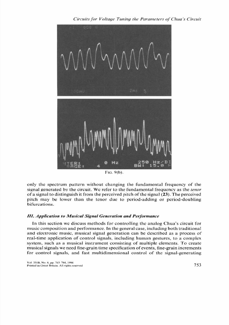
FIG. 12(a). Bifurcation sequence with respect to R(v).
Horizontal axis II<,, scale: (a)-(d) 2 V/div, (e)-(l) 1 V/div, (m) 2 V/div, for trajectories;
Horizontal axis t, scale: (b) 1 msec/div, (c)-(d) 2 msec/div, (e)-(h) 5 msec/div, (i)-(k) 2
msec/div, for time waveforms; Horizontal axis f; scale: (b)-(k) 250 Hz/div, for spectra;
Vertical axis z’<*,scale : (a)-(d) 500 mV/div, (e)-(l) 200 mV/div, (m) 1 V/div, for trajectories ;
Vertical axis Us,, scale : (b)-(e) 2 V/div, (f)-(k) 1 V/div, for time waveforms ; Vertical axis
c<I>scale : 10 dB/div, for spectra.
Parameter values : C,(u,) = 24.45 nF, C,(v,.) = 368.6 nF, L(z>,.)= 38.08 mH (with inherent
series resistance 28.65 a), R,(L),) = 6.32 0, G, = -0.72 mS, G, = -0.5 mS, f E = f 1 V.
(a) c,. = 1.797 V, R(c,) = 1.638 kR, dc equilibrium point.
two attractors for the examples here as the slopes are controlled, as shown in Fig.
14(a)-(b).
4.4. Bifurcation sequence with respect to breakpoints
The locations of the breakpoints of the NR’s z’- i characteristic will also affect
the shape, and consequently the spectrum pattern of the attractor. Moving the
breakpoint closer to the origin will shrink or even suppress one of the lobes in the
double scroll Chua’s attractor. As an example, we show four attractors shrunk by
moving + E and -E closer to the origin, respectively, as shown in Fig. 15(a)-(d).
Note from the pictures that different spectra patterns are obtained as the break-
points move.
V. Concluding Remarks
Chua’s circuit has become a paradigm for studying chaotic dynamics since the
circuit was invented by Chua 10 years ago. The circuit can exhibit a rich variety of
bifurcation sequences and attractors as one or more parameter values of the circuit
are changed. Chaotic circuits such as this produce both harmonic and noise-
like (unstable) signal characteristics, which are important components in musical
signals. The analog Chua’s circuit is an efficient source of complex signals, and the
760

8/7/2019 § - Circuits for Voltage Tuning the Parameters of Chua s Circuit - Experimental Application for Musical Signal Genera…
http://slidepdf.com/reader/full/-circuits-for-voltage-tuning-the-parameters-of-chua-s-circuit-experimental 19/42
Circuits for Voltage Tuning the Parameters of Chua’s Circuit
FIG. 12(b) v,. = 1.922 V, R(v,.) = 1.591 k@ period-l.
Vol. 33lB, No. 6, pp. 743-784, 1994
Prmted in Great Bntain All nghts reserved 761

8/7/2019 § - Circuits for Voltage Tuning the Parameters of Chua s Circuit - Experimental Application for Musical Signal Genera…
http://slidepdf.com/reader/full/-circuits-for-voltage-tuning-the-parameters-of-chua-s-circuit-experimental 20/42
G.-Q. Zhong et al.
762
FIG. 12(c) 0,. = 1.952 V, R(c,) = 1.581 kfi, period-2.
Journal of-the Frankhn lnstilute
Elsewer Smnce Ltd

8/7/2019 § - Circuits for Voltage Tuning the Parameters of Chua s Circuit - Experimental Application for Musical Signal Genera…
http://slidepdf.com/reader/full/-circuits-for-voltage-tuning-the-parameters-of-chua-s-circuit-experimental 21/42
Circuits.fbr Voltage T un ing th e Param eters qf Chu a’s Circuit
FIG;. 12(d) L’,.= 2.002 V, R(c,) = 1.569 kC& Riissler-type attractor.
Vol. 3318, No. 6, P&I 743-784. 1994
Prmted m Grrat Br~tam All rlghts rcser\~ed 763

8/7/2019 § - Circuits for Voltage Tuning the Parameters of Chua s Circuit - Experimental Application for Musical Signal Genera…
http://slidepdf.com/reader/full/-circuits-for-voltage-tuning-the-parameters-of-chua-s-circuit-experimental 22/42
G.-Q. Zhong et al.
F r cL;. 12(e) v, = 2. I78 V, R(o,) = I.533 kR, double scroll attrac ,tor.
764Journal of the Frankhn Institute
Elsewer Scmm Ltd

8/7/2019 § - Circuits for Voltage Tuning the Parameters of Chua s Circuit - Experimental Application for Musical Signal Genera…
http://slidepdf.com/reader/full/-circuits-for-voltage-tuning-the-parameters-of-chua-s-circuit-experimental 23/42
Circuits for Voltage Tuning the Parameters of Chua’s Circuit
F IG;. 12(f) v, = 2.746 V, R(v,.) = 1.433 kQ, double scroll attractor.
Vol. 3318, No. 6, pp 743-784, 1994
Printed in Great Britain All rights reserved 765

8/7/2019 § - Circuits for Voltage Tuning the Parameters of Chua s Circuit - Experimental Application for Musical Signal Genera…
http://slidepdf.com/reader/full/-circuits-for-voltage-tuning-the-parameters-of-chua-s-circuit-experimental 24/42
G.-Q. Zhong et al.
Fu 3. 12(g) c’, = 2.778 V, R(z;,.) = 1.427 kR, R6ssler-type attrac :tor.
766Journal of the Frdnkhn
Elswier Sc

8/7/2019 § - Circuits for Voltage Tuning the Parameters of Chua s Circuit - Experimental Application for Musical Signal Genera…
http://slidepdf.com/reader/full/-circuits-for-voltage-tuning-the-parameters-of-chua-s-circuit-experimental 25/42
Circuits for Voltage Tuning the Parameters of Chua’s Circuit
FIG. 12(h) t’, = 2.799 V, R(t),.)= 1.424 kQ, period-3 window
Vol. 3318, No 6, pp 743-784. 1994
Prmted in Great Britam All rights reserved 767
8/7/2019 § - Circuits for Voltage Tuning the Parameters of Chua s Circuit - Experimental Application for Musical Signal Genera…
http://slidepdf.com/reader/full/-circuits-for-voltage-tuning-the-parameters-of-chua-s-circuit-experimental 26/42
G.-Q. Zhong et al
F?G. 12(i) L’,= 2.903 V, R(u,.) = 1.404 kQ, Rbsler-type attract0 lr.
768Journalofthe Franklin lnst~tute
Elsev~er Saence Ltd

8/7/2019 § - Circuits for Voltage Tuning the Parameters of Chua s Circuit - Experimental Application for Musical Signal Genera…
http://slidepdf.com/reader/full/-circuits-for-voltage-tuning-the-parameters-of-chua-s-circuit-experimental 27/42
Circuits,for Voltu~ye Tuning the Parumeters qf’Chua's Circuit
FIG. 12(j) v,. = 2.975 V, R(c,) = 1.388 kC&period-2.
Vol. 33lB, No. 6, pp 743-784. 1994
Printed m Great Britain All nghts reserved 769

8/7/2019 § - Circuits for Voltage Tuning the Parameters of Chua s Circuit - Experimental Application for Musical Signal Genera…
http://slidepdf.com/reader/full/-circuits-for-voltage-tuning-the-parameters-of-chua-s-circuit-experimental 28/42
G.-Q. Zhong et al.
770
FIG. 12(k) ZI,= 3.087 V, R(z),) = 1.363 kti, period-l.

8/7/2019 § - Circuits for Voltage Tuning the Parameters of Chua s Circuit - Experimental Application for Musical Signal Genera…
http://slidepdf.com/reader/full/-circuits-for-voltage-tuning-the-parameters-of-chua-s-circuit-experimental 29/42
Circuits,for Voltage Tuning the Parameters of’Chua’s Circuit
FIG. 12(l) z’, = 3.317 V. R(o,) = 1.312 kR, dc equilibrium point; (m) c, = 3.553 V, R(r,) =
1.253kQ, large limit cycle corresponding to outer segments of the z;- i characteristic.
simultaneous tuning of multiple parameters increases its efficiency. This paper
presents a multiple-controlled Chua’s circuit in which each parameter value of
Chua’s circuit can be voltage-controlled in real-time, regardless of the type of
control signal, time-delayed or real-time. In this way, distinct bifurcation sequences,
attractors, and spectrum patterns can be observed in real-time. The basic circuit
discussed here has been utilized to successfully generate musical signals in live
interactive computer-controlled performances of the composition “anti-Odysseus :
the irreversibility of time” during Expo ‘93 in Seoul and Taejon, Korea (32).
Note from the observations presented in the paper that the fundamental fre-
quency of the attractor will be changed when the energy-storage elements (capacitor
and inductor) are adjusted. Adjustments of the other parameters in the circuit will
only affect the spectrum patterns, i.e. the frequency components of the attractors.
This property will benefit musicians when they utilize the multiple-control Chua’s
Vol 33lB, No. 6, pp. 7435784, 1994
Prmted ,n Great Bnta~n. All rights reserved 771

8/7/2019 § - Circuits for Voltage Tuning the Parameters of Chua s Circuit - Experimental Application for Musical Signal Genera…
http://slidepdf.com/reader/full/-circuits-for-voltage-tuning-the-parameters-of-chua-s-circuit-experimental 30/42
HOI
time
200
Par,
FIG. 13. Bifurcation sequence with respect to L(L:).
izontal axis 2),, , scale : 1 V/div, for trajectories ; Horizontal axis I, scale : 5 ms/div
: waveforms ; Horizontal axis ,f; scale : 250 Hz/div, for spectra ; Vertical axis c,?, SI
mV/div, for trajectories ; Vertical axis v, ,, scale : 2 V/div, for time waveforms ; Ver
axis Y<, , scale : 10 dB/div, for spectra.
ameter values: C,(L’,.) = 24.45 nF, Cz(r:() = 368.6 nF, R(r,) = 1.533 k0, R,,(z
6.32 Q, G, = -0.72 mS, G,, = -0.5 mS, fE = f 1 V.
(a) r’, = 1.371 V, L(r;,) = 44.11 mH (with inherent series resistance 33.69 Q).
, for
tale :
1,)=

8/7/2019 § - Circuits for Voltage Tuning the Parameters of Chua s Circuit - Experimental Application for Musical Signal Genera…
http://slidepdf.com/reader/full/-circuits-for-voltage-tuning-the-parameters-of-chua-s-circuit-experimental 31/42
Circuits for Voltage Tuning the Parameters of Chua’s Circuit
FIG. 13(b) L’,= 1.271 V, L(v,.) = 43.62 mH (with inherent series resista nce 33.33 CI)
Vol. 3318, No. 6, pp. 7435784 , 1994
Prmt ed in Great Brita m All rights reserved 773

8/7/2019 § - Circuits for Voltage Tuning the Parameters of Chua s Circuit - Experimental Application for Musical Signal Genera…
http://slidepdf.com/reader/full/-circuits-for-voltage-tuning-the-parameters-of-chua-s-circuit-experimental 32/42
Horizontal axis
(b) 5 ms/di, v, fo1
axis c,?, scale :
Parameter valu
6.32 Q, L(z,,,I =
FIG. 14. Bifurcation sequence with respect to slopes.
U, , , scale : 2 V/div, for trajectories ; Horizontal axis t, scale : (r time waveforms ; Horizontal axis,f, scale : 250 Hz/div, for spel
200 mV/div, for trajectories; Vertical axis r, ,, scale: 2 V/I
waveforms ; Vertical axis L’,,, scale : 10 dB/div, for spectra.
[es: C,(o,) = 24.45 nF, C?(z’,) = 368.6 nF, R(u,) = 1.533 L
38.08 mH (with inherent series resistance 28.65 !A), k E = +
5.856 V, G,, = -0.7 mS, Gh = -0.45 mS.
a) I 0 ms
ctra ; Vet
div, for
s2, ML ><)=IV (a) c, =
/div,
time

8/7/2019 § - Circuits for Voltage Tuning the Parameters of Chua s Circuit - Experimental Application for Musical Signal Genera…
http://slidepdf.com/reader/full/-circuits-for-voltage-tuning-the-parameters-of-chua-s-circuit-experimental 33/42

8/7/2019 § - Circuits for Voltage Tuning the Parameters of Chua s Circuit - Experimental Application for Musical Signal Genera…
http://slidepdf.com/reader/full/-circuits-for-voltage-tuning-the-parameters-of-chua-s-circuit-experimental 34/42
Hor
t, SC
250
Par:
6.32
FIG. 15. Bifurcation sequence with respect to breakpoints.
izontal axis 2’,, , scale : (a), (c), (d) 2 V/div, (b) 1 V/div, for trajectories ; Horizontal axis
,ale : (a)-(b) 5 ms/div, (c)-(d) 10 ms/div, for time waveforms ; Horizontal axis,/; scale :
Hz/div, for spectra ; Vertical axis t’,?, scale : 200 mV/div, for trajectories ; Vertical axis
scale : 2 V/div, for time waveforms ; Vertical axis c, , , scale : 10 dB/div, for spectra.
imeter values: C,(n,) = 23.60 nF, C,(L.,) = 368.6 nF, R(c) = 1.533 kR, R,(r),.) =
: Cl, L(nJ = 38.08 mH (with inherent series resistance 28.65 Q), G, = -0.72 mS, G, =
-OSmS.(a)c, =3.847V, +E= +0.65V, --E= -1 V.

8/7/2019 § - Circuits for Voltage Tuning the Parameters of Chua s Circuit - Experimental Application for Musical Signal Genera…
http://slidepdf.com/reader/full/-circuits-for-voltage-tuning-the-parameters-of-chua-s-circuit-experimental 35/42
Circuits for Voltage Tuning the Parameters 9f‘Chua’s Circuit
FI G. 15(b) c, = 2.415 V, +E = +0.35 v, --E = -1 V.
Vol 3318, No 6, pp. 743-784, 1994
Pnnted m Great Britain. All righls rcscrved 777

8/7/2019 § - Circuits for Voltage Tuning the Parameters of Chua s Circuit - Experimental Application for Musical Signal Genera…
http://slidepdf.com/reader/full/-circuits-for-voltage-tuning-the-parameters-of-chua-s-circuit-experimental 36/42
G:.Q. Zhong et al.
778
FIG. 15(c) L’, = -5.05OV, +E= +1 V, --E= -0.85 v.

8/7/2019 § - Circuits for Voltage Tuning the Parameters of Chua s Circuit - Experimental Application for Musical Signal Genera…
http://slidepdf.com/reader/full/-circuits-for-voltage-tuning-the-parameters-of-chua-s-circuit-experimental 37/42
Circuits for Voltage Tuning the Parameters of Chua’s Circuit
FIG. 15(d) z),.= -4.385 V, +E = + 1V, -E = -0.65 v.
Vol. 331B. No. 6. pp. 743S784, 1994
Prmted in Great Bntam. All rights reserved 779
8/7/2019 § - Circuits for Voltage Tuning the Parameters of Chua s Circuit - Experimental Application for Musical Signal Genera…
http://slidepdf.com/reader/full/-circuits-for-voltage-tuning-the-parameters-of-chua-s-circuit-experimental 38/42
G.-Q. Zhong et al.
circuit presented in this paper to generate signals for compositions and perform-
ances.
Acknowledgements
This work was supported in part by the Office of Naval Research under Grant NO00 14-
89-J-1402 and by the National Science Foundation under Grant MIP 86-14000. G. Q.
Zhong would like to thank L. 0. Chua for his support and valuable suggestion, I. Choi for
specification discussions and utilizing this model to realize successful performances during
Expo ‘93 in Seoul and Taejon, Korea, and G. Mayer-Kress, B. Shi, C. W. Wu, and L. Pivka
for helpful discussions. R. Bargar would like to thank A. Jackson and L. Arsenault for
discussions of digital simulations of Chua’s circuit, and X. Rodet for assistance with the
real-time circuit simulation and the interface shown in Fig. IO.
References
(1) M. J. Ogorzalek, “Taming chaos : Part II-Control”, IEEE Trans. Circuits 6; SJst.,
Vol. CAS-40, pp. 700-706, 1993.
(2) G. Chen and X. Dong, “From chaos to order-Perspectives and methodologies in
controlling chaotic nonlinear dynamical systems”, Int. J. B(furcations Chuos. Vol. 3,
pp. 136331409, 1993.
(3) G. A. Johnson, T. E. Tigner and E. R. Hunt, “Controlling chaos in Chua’s circuit”,
J. Circuits Syst. Comput., Vol. 3, pp. 109-117, 1993.
(4) K. Murali and M. Lakshmanan, “Controlling of chaos in the driven Chua’s circuit”,
J. Circuits Syst. Cornput., Vol. 3, pp. 1255137, 1993.
(5) G. Chen and X. Dong, “Controlling Chua’s circuit”, J. Circuits Syst. Comput., Vol.
3, pp. 139-149, 1993.
(6) G. Genesio and A. Tesi, “Distortion control of chaotic systems : The Chua’s circuit”,
J. Circuits Syst. Comput., Vol. 3, pp. 151-171, 1993.
(7) T. T. Hartley and F. Mossayebi, “Control of Chua’s circuit”, J. Circuits Syst. Comput.,
Vol. 3, pp. 173-194, 1993.
(8) T. Kapitaniak, Lj. Kocarev and L. 0. Chua, “Controlling chaos without feedback and
control signals”, ht. J. B[furcations Chaos, Vol. 3, pp. 459468, 1993.
(9) L. 0. Chua, “The genesis of Chua’s circuit”, Archiv Elektronik Uhertragungstechnik,
Vol. 46, pp. 250-257, 1992.
(10) T. Matsumoto, “A chaotic attractor from Chua’s circuit”, IEEE Trans. Circuits &Syst., Vol. CAS-31, pp. 105551058, 1984.
(11) G. Q. Zhong and F. Ayrom, “Experimental confirmation of chaos from Chua’s
circuit”, Int. J. Circuit Theory Appl., Vol. 13, pp. 93-98, 1985.
(12) G. Q. Zhong and F. Ayrom, “Periodicity and chaos in Chua’s circuit”, IEEE Trans.
Circuits & Syst., Vol. CAS-32, pp. 501-503, 1985.
(13) T. Matsomoto, L. 0. Chua and R. Tokunaga, “Chaos via torus breakdown”, IEEE
Trans. Circuits & Syst., Vol. CAS-34, pp. 24&253, 1987.
(14) T. S. Parker and L. 0. Chua, “The dual double scroll equation”, IEEE Trans. Circuits
& Syst., Vol. 34, pp. 1059-1073, 1987.
(15) s. wu, “Chua’s circuit family”, Proc. IEEE, Vol. 75, pp. 1022-1032, 1987.
(16) P. Bartissol and L. 0. Chua, “The double hook”, IEEE Trans. Circuits & Syst., Vol.
CAS-35, pp. 1512-1522, 1988.
(17) C. P. Silva and L. 0. Chua, “The overdamped double scroll family”, Znt. J. Circuit
Theory Appl., Vol. 16, pp. 2233302, 1988.
780Journalof the Frankhn lnsf~tute
Elsemer Science Ltd

8/7/2019 § - Circuits for Voltage Tuning the Parameters of Chua s Circuit - Experimental Application for Musical Signal Genera…
http://slidepdf.com/reader/full/-circuits-for-voltage-tuning-the-parameters-of-chua-s-circuit-experimental 39/42
Circuits for Voltage Tuning the Parameters of Chua’s Circuit
(18) L. 0. Chua and G. N. Lin, “Canonical realization of Chua’s circuit family”, IEEE
Trans. Circuits & Syst., Vol. CAS-37, pp. 885-902, 1990.
(19) L. 0. Chua, “Global unfolding of Chua’s circuits”, IEICE Trans. Fund. Electron.
Comm. Comput. Sci., Vol. El6A, pp. 104134, 1993.
(20) F. Ayrom and G. Q. Zhong, “Chaos in Chua’s circuit”, Proc. IEE., Pt. D, Vol. 133,
pp. 307-3 12, November 1986.
(21) X. Rodet, “Sound and music from Chua’s circuit”, J. Circuits Syst. Comput., Vol. 3,
pp. 49-61, March 1993.
(22) G. Mayer-Kress, I. Choi, N. Weber, R. Bargar and A. Htibler, “Musical signals from
Chua’s circuit”, IEEE Trans. Circuits & Syst.-ZZ: Analog Digital Signal Processing,
Vol. CAS-40, pp. 688-695, 1993.
(23) I. Choi, “A chaotic oscillator as a musical signal generator in an interactive per-
formance system”, in J. New Music Res., Ghent, Belgium, to appear.
(24) R. Bargar, I. Choi, S. Das and C. Goudeseune, “Model-based interactive sound for
an immersive virtual environment”, in “Proc. Int. Comput. Music Conf.“, Aarhus,Denmark, September 1994.
(25) G. Mayer-Kress, I. Choi and R. Bargar, “Sound synthesis and music composition
using Chua’s oscillator”, in “Proc. Int. Symp. Nonlinear Theory Appl. (Hawaii)“,
Vol. 5 (workshop), pp. 65570, 1993.
(26) M. P. Kennedy, “Robust op amp realization of Chua’s circuit”, Frequenz, Vol. 46, pp.
6680, 1992.
(27) A. Freed, “Tools for rapid prototyping of music sound synthesis algorithms and
control strategies,” in “Proc. Int. Comput. Music Conf.“, San Jose, CA, October
1992.
(28) D. Wessel, “Timbre space as a musical control structure”, Comput. Music J., Vol. 3,
pp. 45-52, 1979.
(29) International MIDI Association, “MIDI 1.O Specification”, North Hollywood : Inter-
national MIDI Association, 1983.
(30) G. Loy, “Musicians make a standard : The MIDI phenomenon”, Comput. Music J.,
Vol. 9, pp. 8-26, 1985.
(31) N. Weber, CCSR, University of Illinois, private communication, September 1993.
(32) I. Choi, “anti-Odysseus : The Irreversibility of Time”, composition for interactive
performance with Chua’s circuit, created in Center for New Music and Audio
Technology (CNMAT) at U. C. Berkeley and Numerical Laboratory at National
Center for Supercomputing Application (NCSA), University of Illinois at Urbana-
Champaign, Premiered in World Expo, Taejon and Seoul, Korea, 2G-23 October,1993.
Appendix
1. Voltage-controlled capacitor C(v,)
The equivalent circuit of the voltage-controlled capacitor in Fig. 3 is shown in Fig. A( 1).
By applying Kirchhoff s Voltage Law (KVL) to the circuit shown in Fig. A( 1), we have
i=Cdt
=c
Let C(u) be the equivalent capacitance between the two terminals. Then
Vol. 331B, No. 6, pp. 743-784, 1994
Prmted in Great Britam. All nghts reserved 781

8/7/2019 § - Circuits for Voltage Tuning the Parameters of Chua s Circuit - Experimental Application for Musical Signal Genera…
http://slidepdf.com/reader/full/-circuits-for-voltage-tuning-the-parameters-of-chua-s-circuit-experimental 40/42
G.-Q. Zhong et al
i
V
--l C
VVC
P-
10”
7
FIG. A(1). The equivalent circuit of voltage-controlled capacitor.
i = C(r;,)$,
i.e.
C(n,)=C l-&.i 1
2. Voltu gge-cont rolled ind uctor L(c,)
The equivalent circuit of the voltage-controlled inductor in Fig. 4 is shown in Fig. A(2).
By applying KVL to the equivalent circuit in Fig. A(2), we have
Let L(v,) be the equivalent inductance between the two terminals, i.e.
Thus we obtain
i
V
L
-!I-
Vv,
1ov
FIG. A(2). The equivalent circuit of voltage-controlled inductor.
782Journal of the Franklin lnstltute
Elsewer Saence Ltd

8/7/2019 § - Circuits for Voltage Tuning the Parameters of Chua s Circuit - Experimental Application for Musical Signal Genera…
http://slidepdf.com/reader/full/-circuits-for-voltage-tuning-the-parameters-of-chua-s-circuit-experimental 41/42
Circuits for Voltage Tuning the Parameters of Chua’s Circuit
i
FIG. A(3). The equivalent circuit of voltage-controlled resistor.
LL(0,) = p.
1-z”1ov
3. Voltage-controlled resistor R(zj,.)
The equivalent circuit of the voltage-controlled resistor in Fig. 5 is shown in Fig. A(3).
By applying KVL to the equivalent circuit in Fig. A(3), we have
Substituting t’ = iR(u,) for u above gives
RR(v,.) = ~
1-c’1ov
4. Voltage-controlled resistor withjoating terminals
The equivalent circuit of the voltage-controlled resistor with floating terminals in Fig. 6,
is shown in Fig. A(4).
By applying KVL to the equivalent circuit, we have
7 7
FIG. A(4). The equivalent circuit of voltage-controlled resistor with floating terminals.
Vol. 33lB. No. 6, pp 743-784. 1994
Prmted m Great Britain All rights reserved 783

8/7/2019 § - Circuits for Voltage Tuning the Parameters of Chua s Circuit - Experimental Application for Musical Signal Genera…
http://slidepdf.com/reader/full/-circuits-for-voltage-tuning-the-parameters-of-chua-s-circuit-experimental 42/42
G.-Q. Zhong et al.
where Au = c’, -v2.
Let R, (v,) and R,(c,) denote the voltage-controlled resistances for left branch and right
branches of the equivalent circuit shown in Fig. A(4), respectively. Then we have
v, = i, R, (v,.),
zj2 = i,R,(z,,),
Al&/
v, -Us = Au = i,R,(o,)-i,R,(u,.) = ___R [R,(v,.)+&(vOl.
Thus the voltage-controlled resistance R(tl,) with floating terminals above ground between
terminals a and b is
RR(v,) = R,(v,)+R,(u,) =p.
v,
IOV
Related Documents


![Basic of Electrical Circuits1 Introduction [Chua, Desoer & Kuh Linear and Nonlinear Circuits, pp. 1-45] Physical Circuit The Fundamental Variables Lumped Circuit Electric Circuit and](https://static.cupdf.com/doc/110x72/608758e55e6b9e7a7d08d92c/basic-of-electrical-circuits-1-introduction-chua-desoer-kuh-linear-and-nonlinear.jpg)