CNU Dept. of Electronics D. J. Kim 1 Lecture on Communication Theory Chapter 3. Continuous-wave modulation 3.1 Introduction modulation:the process by which some characteristic of a carrier is varied in accordance with a modulating wave(signal) 3.2Amplitude Modulation 1. Am 1) Sinusoidal carrier wave c(t)=A c cos(2f c t) 2) AM signal s(t) =A c [1+k a m(t)] cos(2f c t) m(t) baseband m(t)cos(w c t) passband cos(w c t ) carrier frequency carrier amplitude message signal amplitude sensitivity

Welcome message from author
This document is posted to help you gain knowledge. Please leave a comment to let me know what you think about it! Share it to your friends and learn new things together.
Transcript

CNU Dept. of Electronics
D. J. Kim1
Lecture on Communication Theory
Chapter 3. Continuous-wave modulation
3.1 Introduction
modulation: the process by which some characteristic of a carrier is varied in accordance with a
modulating wave(signal)
3.2 Amplitude Modulation
1. Am1) Sinusoidal carrier wave c(t)=Ac cos(2fct)
2) AM signal s(t) =Ac [1+ka m(t)] cos(2fct)
m(t)baseband
m(t)cos(wct)passband
cos(wct)
carrier frequencycarrier amplitude
message signalamplitude sensitivity

CNU Dept. of Electronics
D. J. Kim2
Lecture on Communication Theory
3) s(t) 의 envelop 이 m(t) 와 똑같은 shape 이 될 조건a) | Kam(t) | < 1 for all t
b) fc >> W where W is message BW
CNU Dept. of Electronics
D. J. Kim3
Lecture on Communication Theory
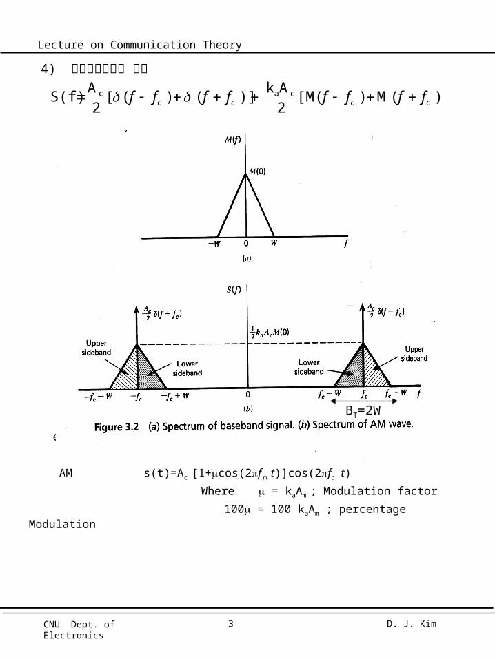
4) 주파수상에서의 표현
ex1) Single-Tone Modulator message m(t)=Am cos(2f m t )
AM s(t)=Ac [1+cos(2f m t)]cos(2fc t) Where = kaAm ; Modulation factor
100 = 100 kaAm ; percentage Modulation
)] (M ) ([M2Ak )] ( ) ( [
2A S(f) cac
cccc ffffffff
BT=2W

CNU Dept. of Electronics
D. J. Kim4
Lecture on Communication Theory
modulation 100%1 if
power totalpower band side total
31
2 2
2
A 81 power frequency -side-Lower
A 81 power frequency -side-Upper
A21 power Carrier
2c
2
2c
2
2c

CNU Dept. of Electronics
D. J. Kim5
Lecture on Communication Theory
2. Switching Modulation
v1(t) = Accos(2(t)) + m(t))
If m(t) Ac
v2(t) v1(t), c(t) > 0
0, c(t) <0
v2(t) [AC cos(2(t)) + m(t))] gTo(t)
where T0=1/fc
m(t)
BPF[v2(t)]

CNU Dept. of Electronics
D. J. Kim6
Lecture on Communication Theory
Diode function
By Fourier series
1n2tf2cos1n2
121
c1n
1n
2 (t)gTo
signal AM
(t)vBPF
)cos(6 )cos(4
2
cff2 )tf2cos()t(mA41
2A
)tf()tf(
)t(m21)tf2cos()t(m
A41
2A
1n2tf2cos1n2
121)t(mtf2cosA)t(v
cc
c
cc
cc
c
c1n
1n
cc2
on off
CNU Dept. of Electronics
D. J. Kim7
Lecture on Communication Theory
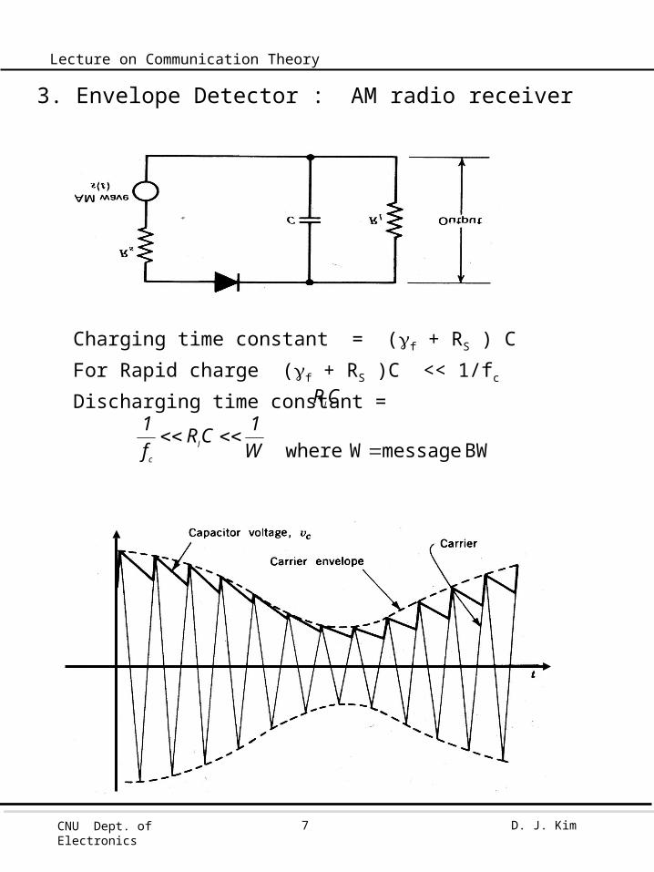
3. Envelope Detector : AM radio receiver
Charging time constant = (f + RS ) C
For Rapid charge (f + RS )C << 1/fc
Discharging time constant =
BW message Wwhere
W1CR
f1
l
c
CRl

CNU Dept. of Electronics
D. J. Kim8
Lecture on Communication Theory

CNU Dept. of Electronics
D. J. Kim9
Lecture on Communication Theory
3.3 Virtues, Limitations , and Modifications of AM
1. Virtues 1) easy modulator: switching mod, square-law modulator demodulator: envelop detector, square-law detector2) relatively cheap
2. Limitations1) Wasteful of power carrier power2) Wasteful of BW 1/2 로 줄일 수 있다 .
LSB 와 USB 가 symmetry.
3. Modifications of AM1) DSB-SC modulation : no carrier2) VSB modulation : BW 를 약 1/2 로3) SSB modulation : BW 를 1/2 로
CNU Dept. of Electronics
D. J. Kim10
Lecture on Communication Theory
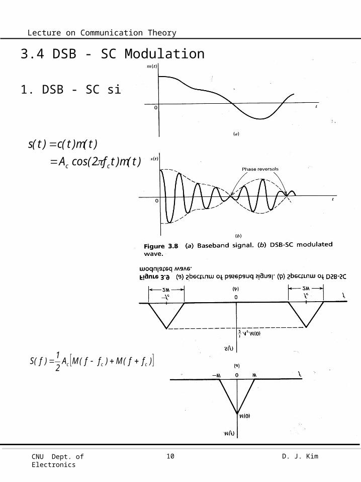
3.4 DSB - SC Modulation
1. DSB - SC signal
)t(m)tf2cos(A)t(m)t(c)t(s
cc
)ff(M)ff(MA21)f(S ccc
CNU Dept. of Electronics
D. J. Kim11
Lecture on Communication Theory
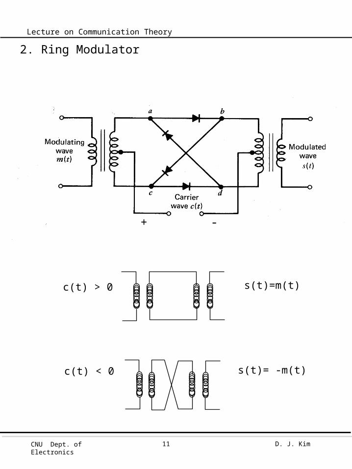
2. Ring Modulator
c(t) > 0 s(t)=m(t)
c(t) < 0 s(t)= -m(t)
+ -
CNU Dept. of Electronics
D. J. Kim12
Lecture on Communication Theory
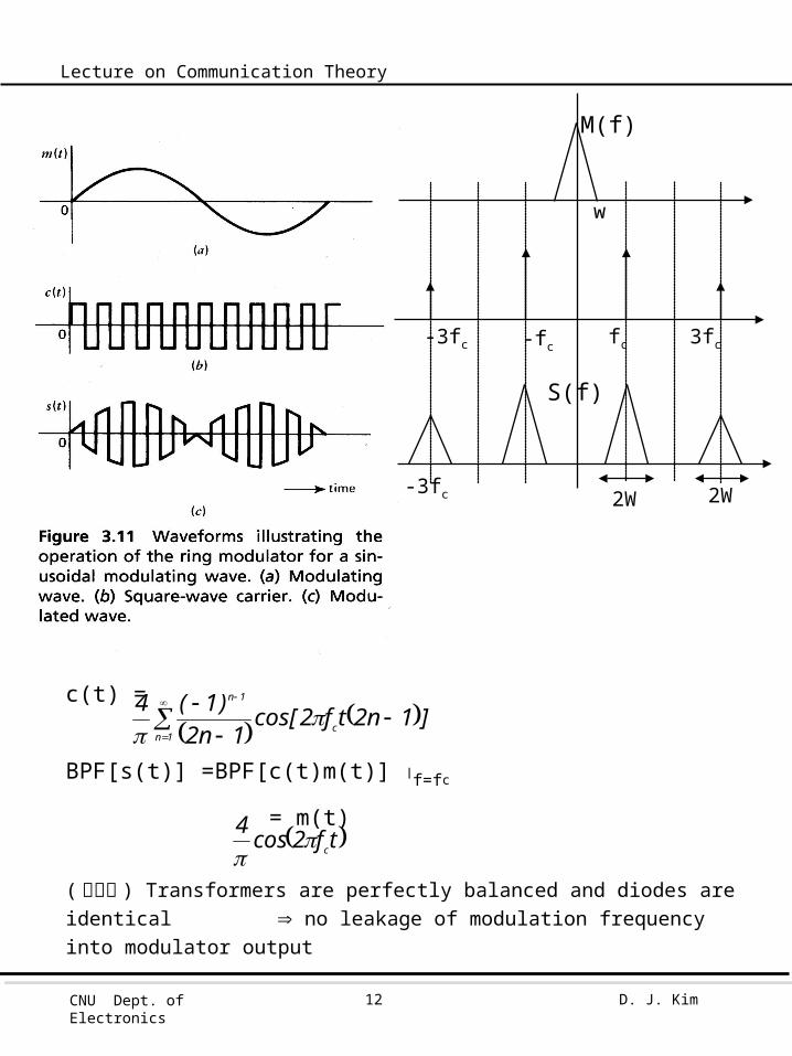
c(t) =
BPF[s(t)] =BPF[c(t)m(t)] f=fc
= m(t)
( 주의점 ) Transformers are perfectly balanced and diodes are identical no leakage of modulation frequency into modulator output
]1n2tf2cos[1n2
)1(4c
1n
1n
tf2cos4c
2W2W
-fc fc 3fc-3fc
w
-3fc
M(f)
S(f)
CNU Dept. of Electronics
D. J. Kim13
Lecture on Communication Theory
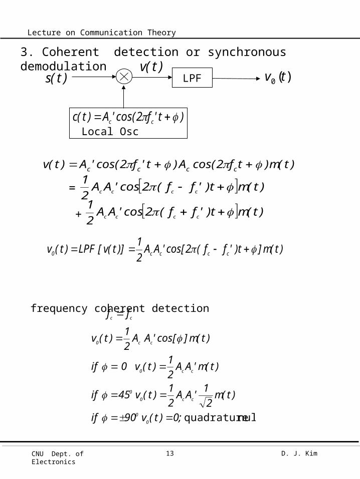
3. Coherent detection or synchronous demodulation
frequency coherent detection
'ff cc
null quadrature
;0)t(v90if
)t(m2
1'AA21)t(v45if
)t(m'AA21)t(v0if
)t(m]cos['AA21)t(v
00
cc00
cc0
cc0
LPF
)t'f2cos('A)t(c cc Local Osc
)(0 tv)t(s
)t(m]t)'ff(2cos['AA21)]t(v[LPF)t(v cccc0
)t(m)tf2cos(A)t'f2cos('A)t(v cccc
)t(mt)'ff(2cos'AA21
cccc
)t(mt)'ff(2cos'AA21
cccc =
+
)t(v

CNU Dept. of Electronics
D. J. Kim14
Lecture on Communication Theory
Coherent Detection 특징 : perfect demodulation but 복잡 cost
4. Costas Receiver
)t(m'AA21)t(v
0,'ff
cc0
cc
: coherent phase &frequency
00Q
)t(mI: torDiscrimina Phase
real : m(t)근거구현
V(f)
2wf-2fc 2fc
2w

CNU Dept. of Electronics
D. J. Kim15
Lecture on Communication Theory
sin
1sin
)t(mcos)t(msin
, φφsin1φcos
,
channel Ichannel Q small for
빠른 주파수
늦은 주파수 정상주파수
s(t)
OSC
450
- 450
CNU Dept. of Electronics
D. J. Kim16
Lecture on Communication Theory
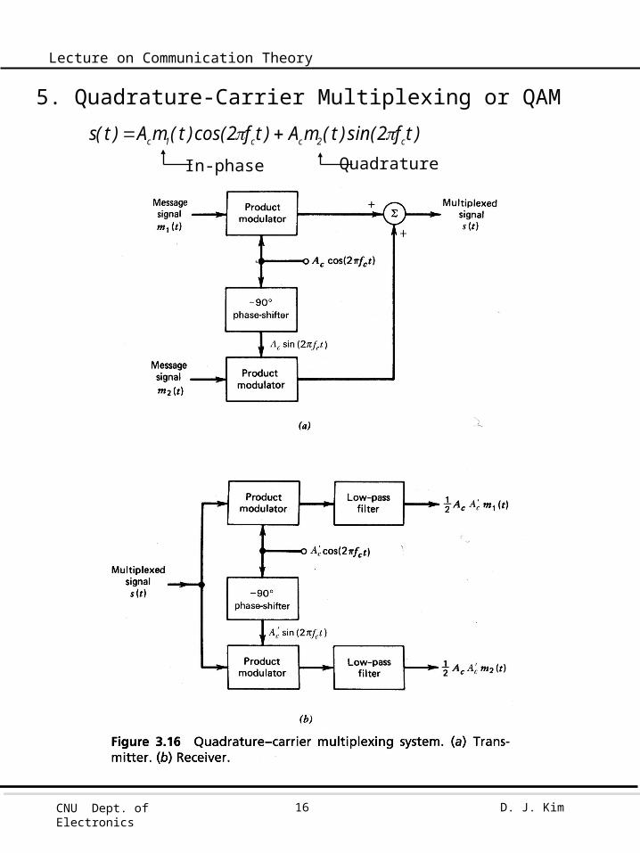
5. Quadrature-Carrier Multiplexing or QAM
)tf2sin()t(mA)tf2cos()t(mA)t(s c2cc1c
In-phase Quadrature
CNU Dept. of Electronics
D. J. Kim17
Lecture on Communication Theory
Key points> Correct phase & frequencyCostas Receiver 사용
Send a pilot signal outside the passband of the modulated signalPilot : Low power sinusoidal tone whose frequency and phase are
related to c(t)Add pilot signal of small carrier
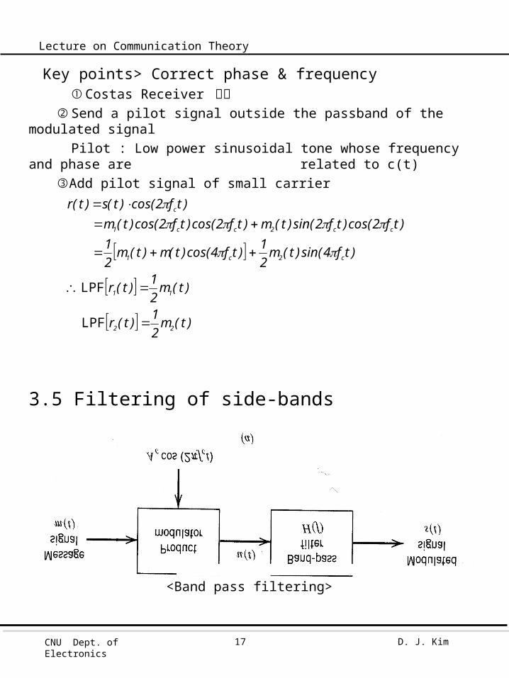
3.5 Filtering of side-bands
)t(m21)t(r
)t(m21)t(r
)tf4sin()t(m21)tf4cos()t(m)t(m
21
)tf2cos()tf2sin()t(m)tf2cos()tf2cos()t(m)tf2cos()t(s)t(r
22
11
c2c1
cc2cc1
c
LPF
LPF
<Band pass filtering>

CNU Dept. of Electronics
D. J. Kim18
Lecture on Communication Theory
1.BPF 의 LSB 와 USB 가 symmetric 할 경우
2. BPF 의 LSB 와 USB 가 unsymmetric 할 경우
H(f)
-fc fc
f
LPFm(t) s(t)
)tf2cos(A cc
0
-fc fc
FILTERHQ(T)
FILTERHi(T)
m(t)
CNU Dept. of Electronics
D. J. Kim19
Lecture on Communication Theory
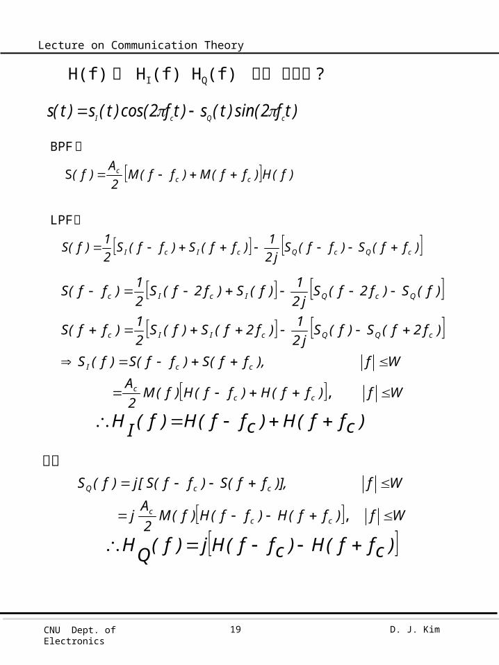
H(f) 와 HI(f) HQ(f) 간의 관계는 ?
또한
)tf2sin()t(s)tf2cos()t(s)t(s cQcI
)ff(S)ff(Sj2
1)ff(S)ff(S21)f(S
)f(H)ff(M)ff(M2A
)f(
cQcQcIcI
ccc
LPF
S
BPF
식
식
,
)cff(H)cff(H)f(IH
Wf)ff(H)ff(H)f(M2A
Wf),ff(S)ff(S)f(S
)f2f(S)f(Sj2
1)f2f(S)f(S21)ff(S
)f(S)f2f(Sj2
1)f(S)f2f(S21)ff(S
ccc
ccI
cQQcIIc
QcQIcIc
,
)cff(H)cff(Hj)f(QH
Wf)ff(H)ff(H)f(M2A
j
Wf)],ff(S)ff(S[j)f(S
ccc
ccQ
CNU Dept. of Electronics
D. J. Kim20
Lecture on Communication Theory
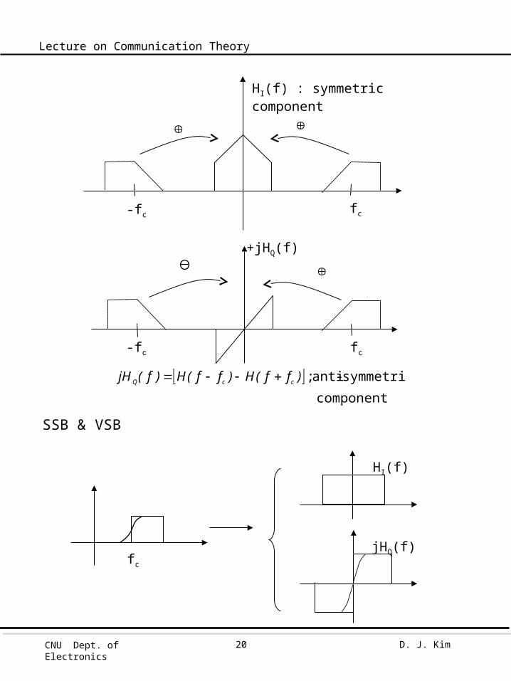
SSB & VSB
fc
HI(f)
jHQ(f)
-fc fc
HI(f) : symmetric component
-fc fc
+jHQ(f)
component
symmetric-anti ; )ff(H)ff(H)f(jH ccQ

CNU Dept. of Electronics
D. J. Kim21
Lecture on Communication Theory
3.6 Vestigial Side-Band Modulation
1. Filtering
1) fc를 중심으로 odd-symmetry
LSB(or USB) 의 vestige 만 보냄 .2) USB or LSB
0.5
0.5
1
1
f
f
fc+Wfcfc-fv
fc-W fc fc-fv
fc+fv
fc+fv
HI
HQ
HI
HQ
CNU Dept. of Electronics
D. J. Kim22
Lecture on Communication Theory
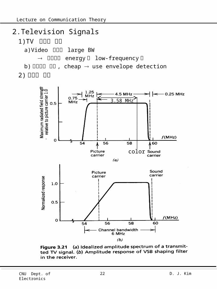
2.Television Signals1)TV 신호의 특징
a)Video 신호가 large BW 대부분의 energy 가 low-frequency 에b) 수신기가 간단 , cheap use envelope detection
2) 주파수 특성
color
3.58 MHz

CNU Dept. of Electronics
D. J. Kim23
Lecture on Communication Theory
3. 0.75 MHz (25%) 의 LSB 를 full scale 로 보내는 이유Envelope detection 에서 waveform distortion 을 줄이기
위해
1) Waveform distortion
add carrier component to apply envelope detector
Envelop detector output
2) m’(t) 에 의한 distortion 을 줄이는 방법a) ka를 줄인다 .
b) Vestigial sideband 의 폭을 늘인다 .
3) TV 신호에서의 해법a) 100% percentage modulationb) 0.75MHz 의 LSB
due to cheap
)tf2sin()t('mAk21)tf2cos()t(mk
211A)t(s ccacac
21
2
a
a
ac
21
2
a
2
ac
)t(mk211
)t('mk21
1)t(mk211A
)t('mk21)t(mk
211A)t(a
negligibledistortion

CNU Dept. of Electronics
D. J. Kim24
Lecture on Communication Theory
3.7 SSB
1. 방법 : USB 나 LSB 만 전송
2. 이유 : Message m(t) 가 실수 M(f) 는 conjugate symmetric
3. 문제점 : LSB 나 USB 가 붙어 있을 경우 filtering 이 어렵다 .4. 적용분야 : Message spectrum 이 origin 에서 energy gap 이 있을 때
ex) Voice (-3400 ~ -300) (300 ~ 3400Hz)
)f(H
f
CNU Dept. of Electronics
D. J. Kim25
Lecture on Communication Theory
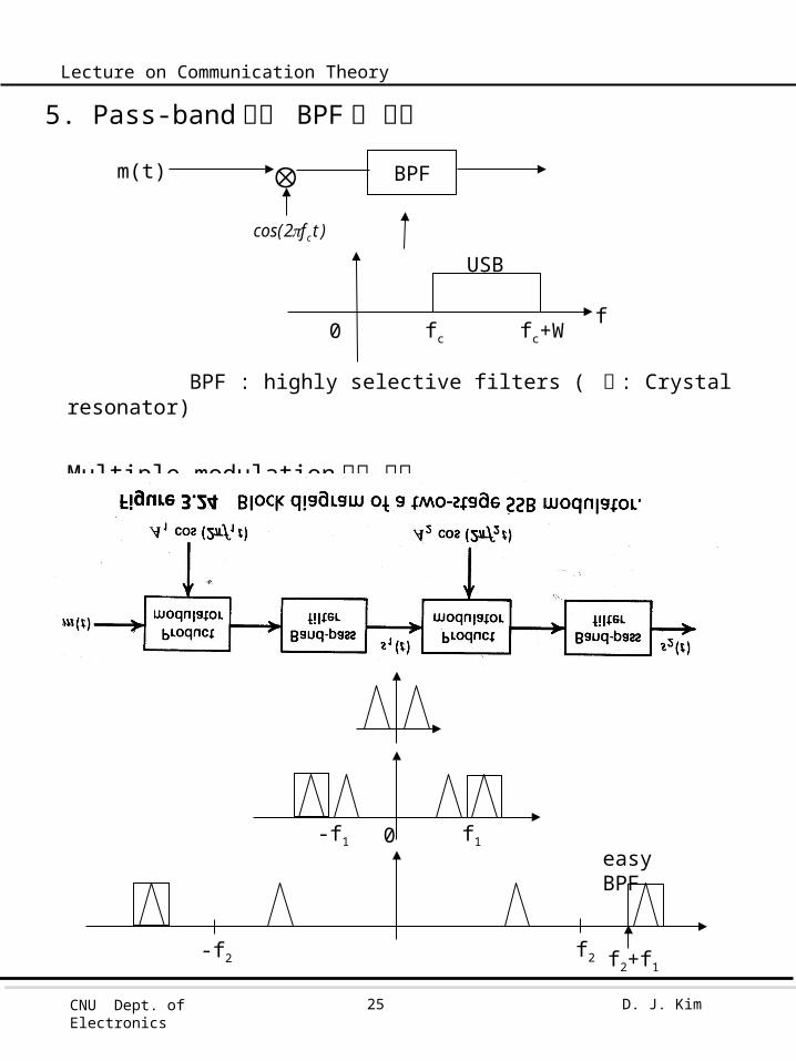
5. Pass-band 에서 BPF 로 구현
BPF : highly selective filters ( 예 : Crystal resonator)
Multiple modulation 으로 구현
m(t) BPF
USB
ffc fc+W0
)tf2cos( c
-f1
f2
f1
-f2
0
f2+f1
easy BPF
CNU Dept. of Electronics
D. J. Kim26
Lecture on Communication Theory
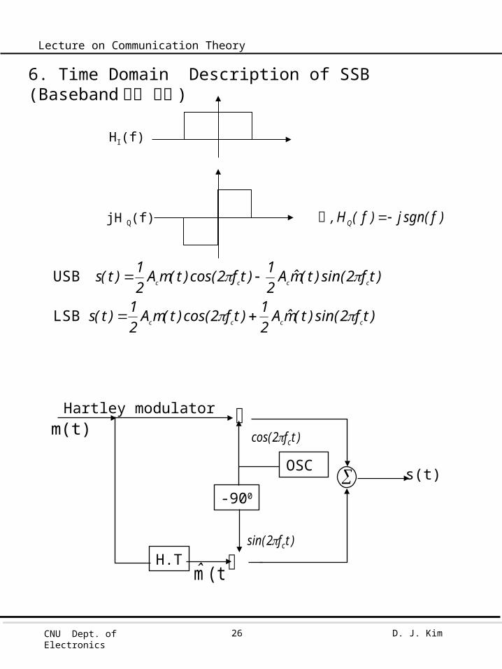
6. Time Domain Description of SSB (Baseband 에서 구현)
Hartley modulator
jH Q(f)
HI(f)
)fsgn(j)f(H, Q 즉
)tf2sin()t(m̂A21)tf2cos()t(mA
21)t(s
)tf2sin()t(m̂A21)tf2cos()t(mA
21)t(s
cccc
cccc
LSB
USB
H.T
-900
OSC
)tf2cos( c
)tf2sin( c
(t)m̂
m(t)
s(t)
CNU Dept. of Electronics
D. J. Kim27
Lecture on Communication Theory
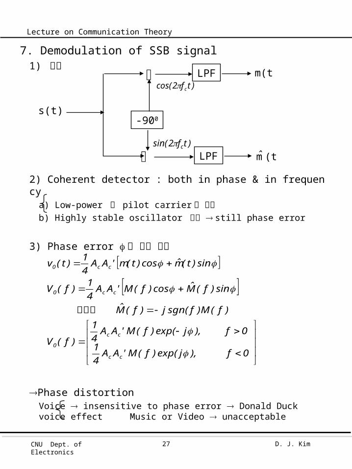
7. Demodulation of SSB signal1) 구현
2) Coherent detector : both in phase & in frequencya) Low-power 의 pilot carrier 를 전송b) Highly stable oscillator 사용 still phase error
3) Phase error 가 있을 경우
Phase distortionVoice insensitive to phase error Donald Duck voice effect
Music or Video unacceptable
-900
)tf2cos( c
)tf2sin( c
s(t)
(t)m̂
m(t)LPF
LPF
0f),jexp()f(M'AA41
0f),jexp()f(M'AA41
)f(V
)f(M)fsgn(j)f(M̂
sin)f(M̂cos)f(M'AA41)f(V
sin)t(m̂cos)t(m'AA41)t(v
cc
cc
0
cc0
cc0
여기서

CNU Dept. of Electronics
D. J. Kim28
Lecture on Communication Theory
3.8 Frequency Translation
f3 = f2 + f1
f5 = f4 + f3= f4 (f2 f1)
= f4(f2-f1)
f4(f2+f1)
UpwardDownward
ex) f1= 0M f2= 44M f3 = 44M
f4= 66M f5 = 110M, 22M
ex) f1=110M f2= 1030M f3 = 920M, 1140M
f4= 876M f5 = 44M, 1796M
f6= 44M f7 = 0M, 88M
f3
f2 f4
f1 f5
TV
DTV

CNU Dept. of Electronics
D. J. Kim29
Lecture on Communication Theory
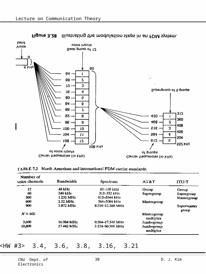
3.9 Frequency-Division Multiplexing
ex2) Voice BW= 4kHz, SSBBasic Groups=12 Voice, fc=60+4nkHz. n=1~12
Super Groups= 5Basic Groups, fc=372+48nkHz. n=1~5
Master GroupVery Large Group
w1 w2 w3 wnf
w1
w2
wn
w1
w2
wn
CNU Dept. of Electronics
D. J. Kim30
Lecture on Communication Theory
<HW #3> 3.4, 3.6, 3.8, 3.16, 3.21
CNU Dept. of Electronics
D. J. Kim31
Lecture on Communication Theory
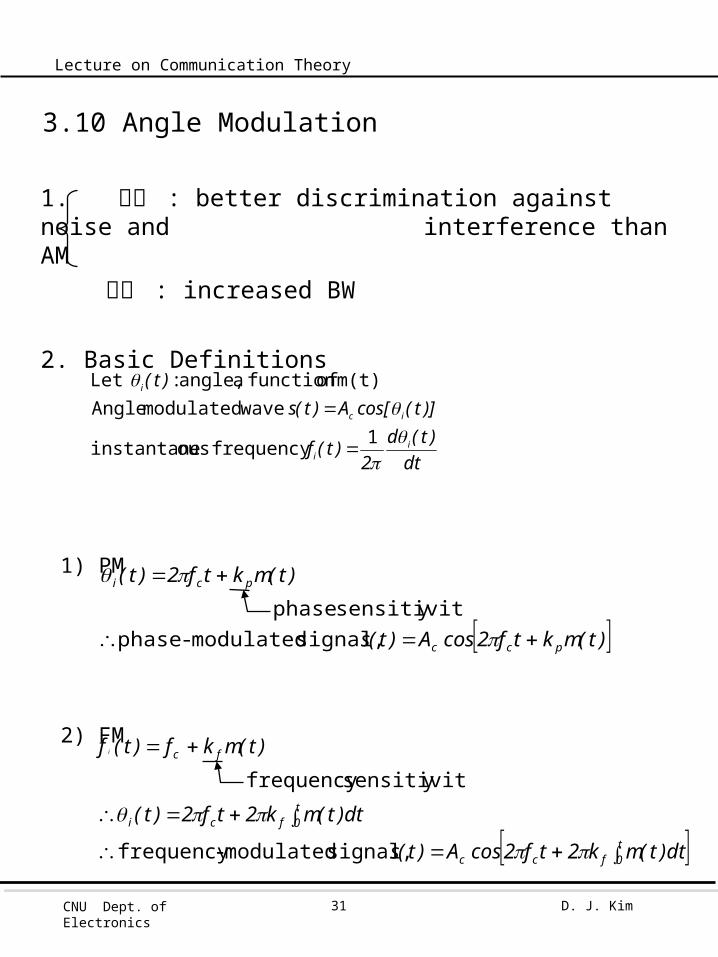
3.10 Angle Modulation
1. 장점 : better discrimination against noise and interference than AM
단점 : increased BW
2. Basic Definitions
1) PM
2) FM
dt)t(d
2)t(f
)]t(cos[A)t(s)t(
ii
ic
i
1 frequency ousinstantane
wavemodulated Anglem(t) of function a angle, : Let
signal, modulated-frequency
ysensitivitfrequency
t0fcc
t0fci
fc
dt)t(mk2tf2cosA)t(s
dt)t(mk2tf2)t(
)t(mkf)t(f i
signal, modulated-phase y sensitivit phase
)t(mktf2cosA)t(s
)t(mktf2)t(
pcc
pci

CNU Dept. of Electronics
D. J. Kim32
Lecture on Communication Theory
3) AM 과 다른점a) AM 은 zero crossing 이 주기적 , PM 과 FM 은 비주기적b) AM 은 envelope 이 변화 , PM 과 FM 은 constant
carrier
m(t)
AM
PM
FM
CNU Dept. of Electronics
D. J. Kim33
Lecture on Communication Theory
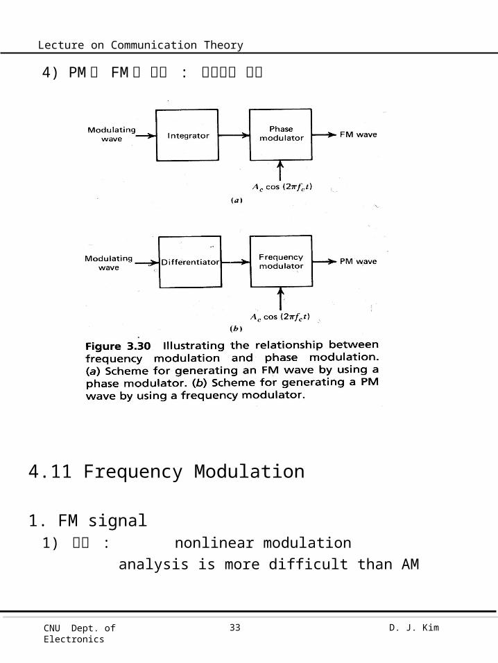
4) PM 과 FM 의 관계 : 미적분의 관계
4.11 Frequency Modulation
1. FM signal1) 특징 : nonlinear modulation
analysis is more difficult than AM

CNU Dept. of Electronics
D. J. Kim34
Lecture on Communication Theory
2) FM signal
f - f :minff :max
deviation)frequency where
c
c
(Akf)tf2cos(ff
)tf2cos(Akf)t(f
mf
mc
mmfci
tf2tf2
tπf2)t(f
Δft)πf2(sintπf2
t)πf2(sinf
Δftπf2
dt)t(f2)t(
c
c
c
m
mc
mm
c
t0 ii
: min :max
angle the from angle the of departure maximum ;
index modulation ; where
phase
i
radian : FM band-wideradian : FM band-narrow
signal FM
11
)tf2sin(tf2cosA)t(s mcc
)tf2cos(Am(t) mm consider
frequency ousinstantane
CNU Dept. of Electronics
D. J. Kim35
Lecture on Communication Theory
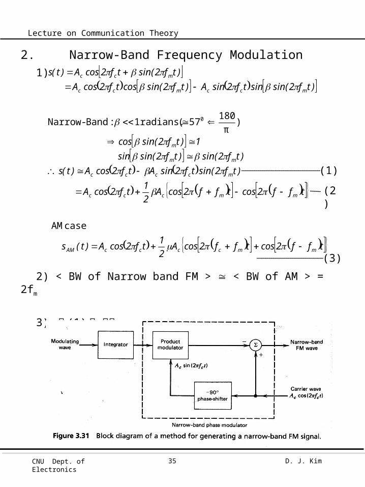
2. Narrow-Band Frequency Modulation1)
2) < BW of Narrow band FM > < BW of AM > = 2fm
3) 식 (1) 의 구현
tff2costff2cosA21tf2cosA)t(s
tff2costff2cosA21tf2cosA
)tf2sin(tf2sinAtf2cosA)t(s)tf2sin()tf2sin(sin
1)tf2sin(cos
)tf2sin(sintf2sinA)tf2sin(costf2cosA)tf2sin(tf2cosA)t(s
mmccccAM
mmccc
mcccc
mm
m
mccmcc
mcc
case AM
)18057( radians. 1 : Band-Narrow
0
π
(1)
(2)
(3)

CNU Dept. of Electronics
D. J. Kim36
Lecture on Communication Theory
4) (2) (3) 식의 그림상에서 비교문제 : envelope 이 변한다
0.3 radians negligible
3. Wide-band FM1) FM wave
m
mc
c
mcc
ftstf2jAts
tf2jtstf2jtf2jAts
withfunctionperiodic : where
)(~sinexp)(~
exp)(~ResinexpRe)(
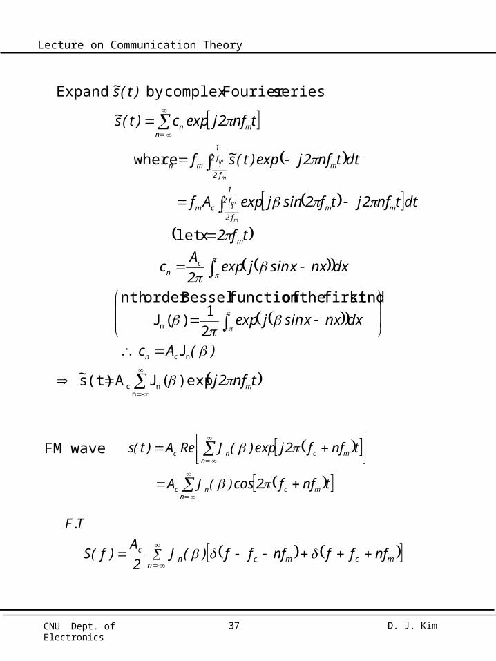
CNU Dept. of Electronics
D. J. Kim37
Lecture on Communication Theory
FM wave
-nnc
n
n
)exp(JA(t)s
J 21)(J
kind first the of function Bessel order nth
xlet
where
series Fouriercomplex by Expand
tnf2j~)(Ac
dxnxxsinjexp
dxnxxsinjexp2Ac
tf2
dttnf2jtf2sinjexpAf
dttnf2jexp)t(s~fc
tnf2jexpc)t(s~
)t(s~
m
cn
cn
m
mmf21
f21cm
mf21
f21mn
nmn
m
m
m
m
nmcnc
nmcnc
tnff2cos)(JA
tnff2jexp)(JReA)t(s
mcmcnn
c nfffnfff)(J2A
)f(S
T.F
CNU Dept. of Electronics
D. J. Kim38
Lecture on Communication Theory
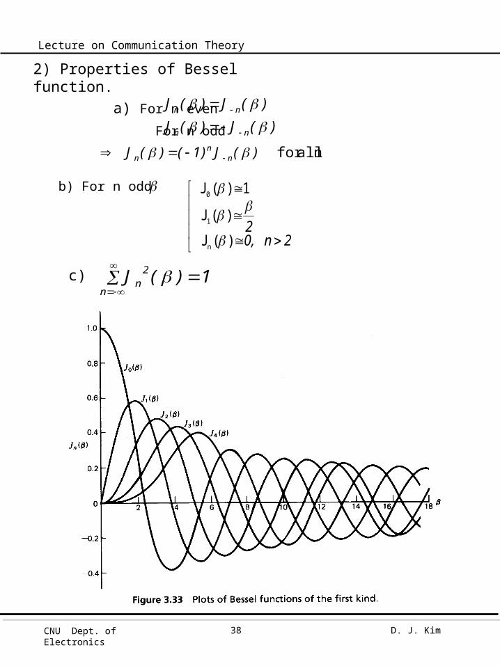
)(J)(J)(J)(J
nn
nn
n all for )(J)1()(J nn
n
2n,02
)(J
)(J
1)(J
n
1
0
n
2n 1)(J
2) Properties of Bessel function. a) For n even For n odd
b) For n odd
c)

CNU Dept. of Electronics
D. J. Kim39
Lecture on Communication Theory
3) Observations.a) Spectrum, fcnfm, n=0,1,2,…...
b) for small , spectrum at fc, fm narrow-band FM
c) Amplitude of carrier component J0() varies with
example 3.Fixed freq (fm) & varying amplitude (i, e, f)
Varing freq(fm) & fixed amplitude (i, e, f)
2
cn
2
n
2
c A21)(JA
21P
index moduiation : mff

CNU Dept. of Electronics
D. J. Kim40
Lecture on Communication Theory
4. Transmission Bandwidth of FM signals.
1) BW of FM 의 개념 .실제 FM: infinite number of side freq.Effectively finite number of side freq.Single tone FM case.
Narrow band : BW order of 2fm
Wide band : BW order of 2f
2) Carson’s ruleApproximate BW of FM by single tone fm
3) BW of FM the separation between the two freq beyond which none of the frequencies is greater
than 1% of the unmodulated carrier amplitude
= 2nmax fm
where nmax=largest value of integer n that satisfies the requirement
m
mT
f)1(2
11f2f2f2B
def
01.0)(J n
2nmax
Carson’s rule
0.1 0.3 0.5 1.0 2.0 5.0 10.0 20.0 30.0 2 4 4 6 8 16 28 50 70
2.2 2.6 3 4 6 12 22 42 62
CNU Dept. of Electronics
D. J. Kim41
Lecture on Communication Theory
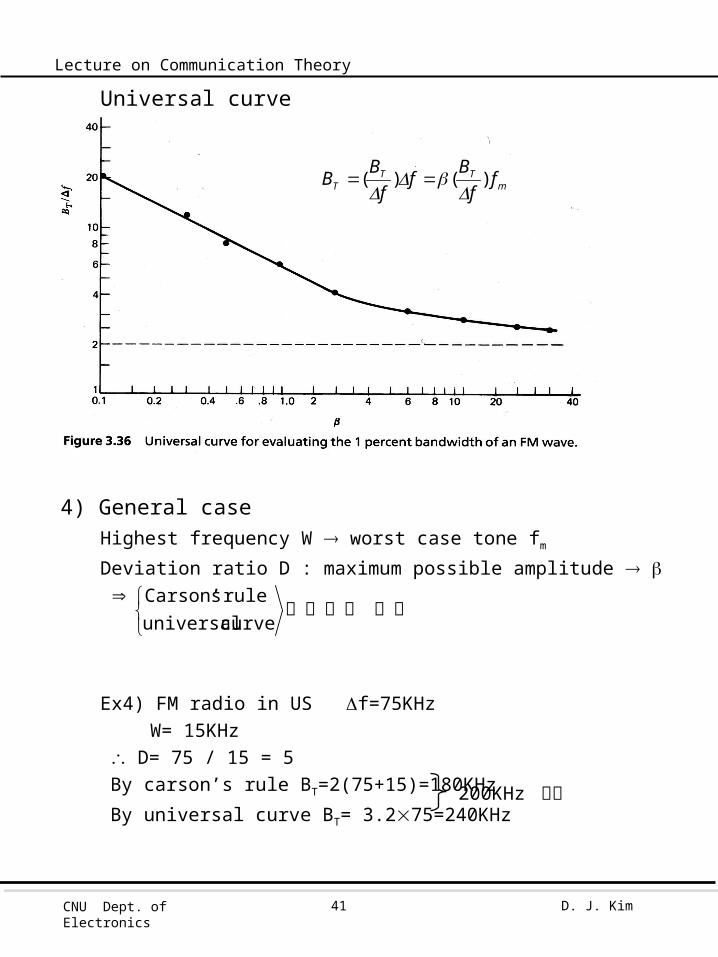
Universal curve
4) General caseHighest frequency W worst case tone fm
Deviation ratio D : maximum possible amplitude
Ex4) FM radio in US f=75KHz W= 15KHz D= 75 / 15 = 5By carson’s rule BT=2(75+15)=180KHz
By universal curve BT= 3.275=240KHz
정결서에이사 curve universal
rule sCarson’
200KHz 사용
mTT
T ff
Bf
fB
B )()(

CNU Dept. of Electronics
D. J. Kim42
Lecture on Communication Theory
5. Genetation of FM signals1) Indirect FM
a) Crystal controlled OSC : to provide frequency stability
b) Frequency multiplier
c) 식 .
t
0fcc
nn
33
221
t
0fcc
dt)t(mnk2tnf2cos'A)t('s
)t(sa......)t(sa)t(sa)t(sa)t(v
dt)t(mk2tf2cosA)t(s
CNU Dept. of Electronics
D. J. Kim43
Lecture on Communication Theory
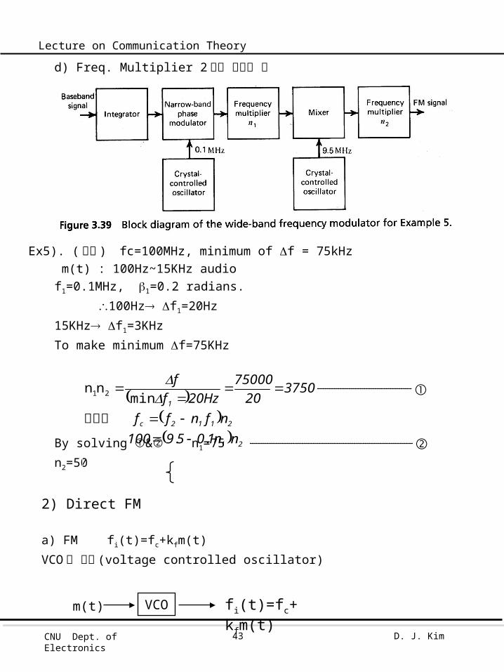
d) Freq. Multiplier 2 개를 사용한 예
Ex5). ( 목적 ) fc=100MHz, minimum of f = 75kHz m(t) : 100Hz~15KHz audiof1=0.1MHz, 1=0.2 radians.
100Hz f1=20Hz
15KHz f1=3KHz
To make minimum f=75KHz
By solving & n1=75
n2=50
2) Direct FM a) FM fi(t)=fc+kfm(t)
VCO 로 구성 (voltage controlled oscillator)
VCO fi(t)=fc+ kfm(t)m(t)
21
2112c
1
nn1059100nfnff
375020
75000Hz20f
f
..
min
nn 21
그리고
CNU Dept. of Electronics
D. J. Kim44
Lecture on Communication Theory
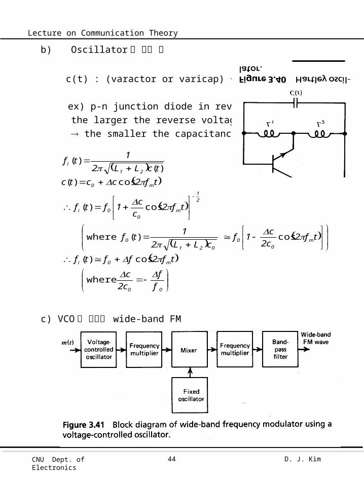
b) Oscillator 의 구현 예
c(t) : (varactor or varicap) + fixed capacitance
ex) p-n junction diode in reverse biasthe larger the reverse voltage the smaller the capacitance
c) VCO 를 이용한 wide-band FM
00
m0i
m0
0
021
0
21
m0
0i
m0
21
i
ff
c2c
tf2fftf
tf2c2c1f
cLL21tf
tf2c
c1ftf
tf2cctc
tcLL21tf
where
where
cos)(
cos)(
cos)(
cos)()(
)(
CNU Dept. of Electronics
D. J. Kim45
Lecture on Communication Theory
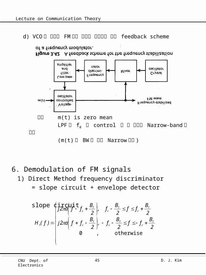
d) VCO 를 이용한 FM 에서 주파수 안정화를 위한 feedback scheme
가정 m(t) is zero mean LPF 는 f0 만 control 할 수 있도록 Narrow-band 로 구현
(m(t) 의 BW 에 비해 Narrow 하게 )
6. Demodulation of FM signals1) Direct Method frequency discriminator
= slope circuit + envelope detector
slope circuit
otherwise , 0
2Bff
2Bf,
2Bffa2j
2Bff
2Bf,
2Bffa2j
)f(H Tc
Tc
Tc
Tc
Tc
Tc
1

CNU Dept. of Electronics
D. J. Kim46
Lecture on Communication Theory
t0fc
T
fcT
c1
t0f
T
fcT
T1
TTT
11
TTT
1
t0fc
t0fcc
2dt)t(mk2tf2cos)t(m
Bk2
1aAB
)tf2jexp()t(s~Re)t(s
dt)t(mk2jexp)t(mBk2
1aABj
)t(s~Bjdt
)t(s~da)t(s~
02
Bf
2B
)f(S~2
Bfa2j
)f(S~)f(H~21)f(S~
02
Bf
2B
2B
fa4j)f(H~
dt)t(mk2jexpA)t(s~s(t)
dt)t(mk2tf2cosA)t(s
otherwise ,
,
otherwise
of envelopecomplex
s(t) s2(t)
s1(t)
so(t)
)(~ ts1
)(~ ts2
< Balanced frequency discriminator >
CNU Dept. of Electronics
D. J. Kim47
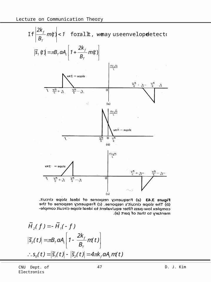
Lecture on Communication Theory
)()(~
)(
tmBk2
1aABts
1tmBk2
T
fcT1
T
f
detector envelope usemay wet, all for If
)t(maAk4)t(s~)t(s~)t(s
)t(mBk2
1aAB)t(s~
)f(H~)f(H~
cf210
T
fcT2
12
CNU Dept. of Electronics
D. J. Kim48
Lecture on Communication Theory
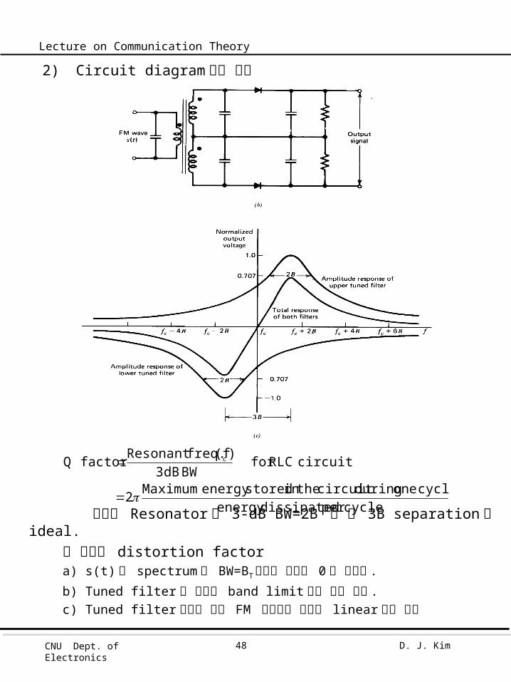
2) Circuit diagram 으로 구현
각각의 Resonator 의 3-dB BW=2B 일 때 3B separation 이 ideal.
위 회로의 distortion factora) s(t) 의 spectrum 이 BW=BT밖에서 완전히 0 이 아니다 .
b) Tuned filter 가 완전히 band limit 되어 있지 않다 .c) Tuned filter 특성이 모든 FM 대역에서 완전히 linear 하지 않다
cycle per dissipatedenergy cycle one during circuit the in storedenergy Maximum2
circuit RLC for BW 3dB
)(f freq. Resonantfactor Q c
CNU Dept. of Electronics
D. J. Kim49
Lecture on Communication Theory
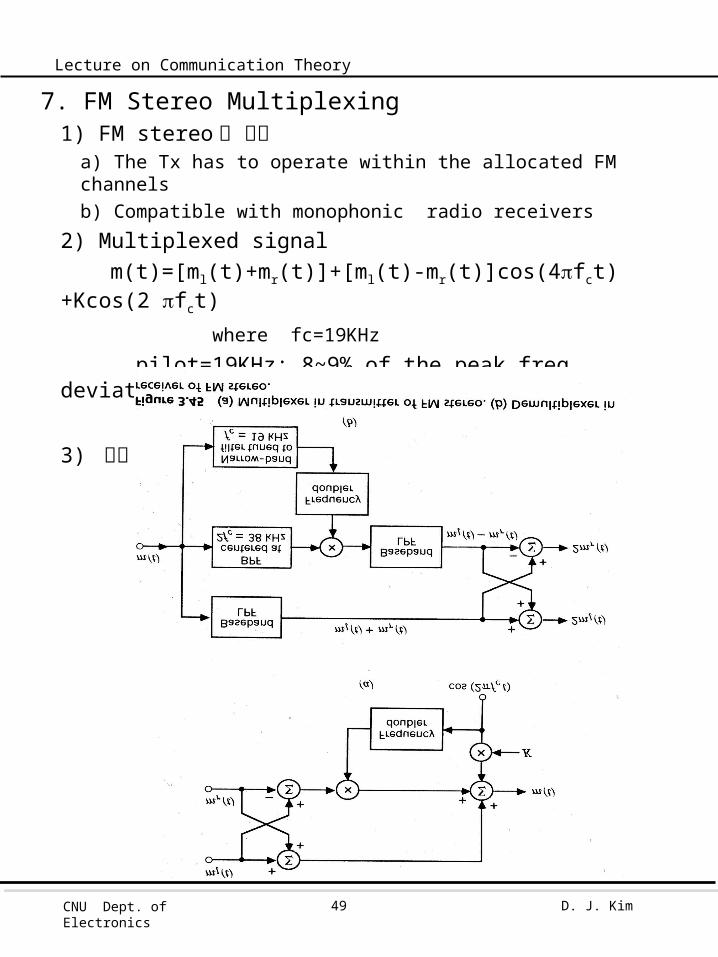
7. FM Stereo Multiplexing1) FM stereo 의 조건
a) The Tx has to operate within the allocated FM channelsb) Compatible with monophonic radio receivers
2) Multiplexed signalm(t)=[ml(t)+mr(t)]+[ml(t)-mr(t)]cos(4fct)+Kcos(2 fct) where fc=19KHz
pilot=19KHz: 8~9% of the peak freq. deviation. ml+mr or ml-mr : DSB-SC
3) 구조
CNU Dept. of Electronics
D. J. Kim50
Lecture on Communication Theory
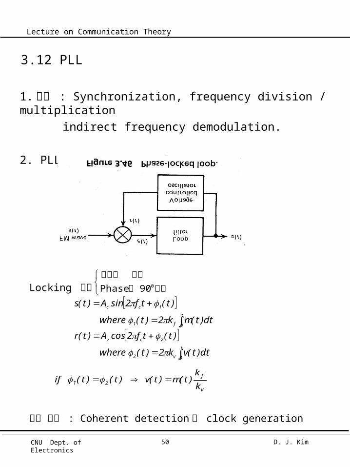
3.12 PLL
1. 용도 : Synchronization, frequency division / multiplicationindirect frequency demodulation.
2. PLL 의 구조
Locking 조건
다른 응용 : Coherent detection 용 clock generation
t
0v2
2cv
t
0f1
1cc
dt)t(vk2)t(where
)t(tf2cosA)t(r
dt)t(mk2)t(where
)t(tf2sinA)t(s
90 Phase
0차이는
동일주파수
v
f21 k
k)t(m)t(v)t()t(if

CNU Dept. of Electronics
D. J. Kim51
Lecture on Communication Theory
3. Nonlinear Model of PLL
여기서 sin( ) : nonlinear function difficult to analyze
4. Linear Model of the PLLNear phase-lock : 즉 e(t)<0.5 radians.
sin[e(t)] e(t)
parameter gain-loop : k where
filter loop : e wher
gain multiplier; here W
0 vcvm
e01e
t
0v1
21e
m
evcm
AAkk
d)t(h)(sinK2dt
)t(ddt
)t(d)t(h)t(h)t(e)t(v
dt)t(vk2)t(
)t()t()t(k
)t(sinAAk)t(e
dt
tdthtK2
dttd 1
e0e )(
)()()(

CNU Dept. of Electronics
D. J. Kim52
Lecture on Communication Theory
BW of h(t)=BW of m(t)
PLL of function transfer loop-open ; wherejf
)f(HKL(f)
)f()f(L1
1)f(
0
1e
)t(mkk
dt)f(d
k21)t(v
)f(kjf)f(V1)f(LIf
)f()f(L1
)f(Lkjf
)f()f(Lkjf)f()f(H
kK
)f(V
v
f1
v
1v
1v
ev
ev
0
output
1(t) dtd
v(t)
vk21
CNU Dept. of Electronics
D. J. Kim53
Lecture on Communication Theory
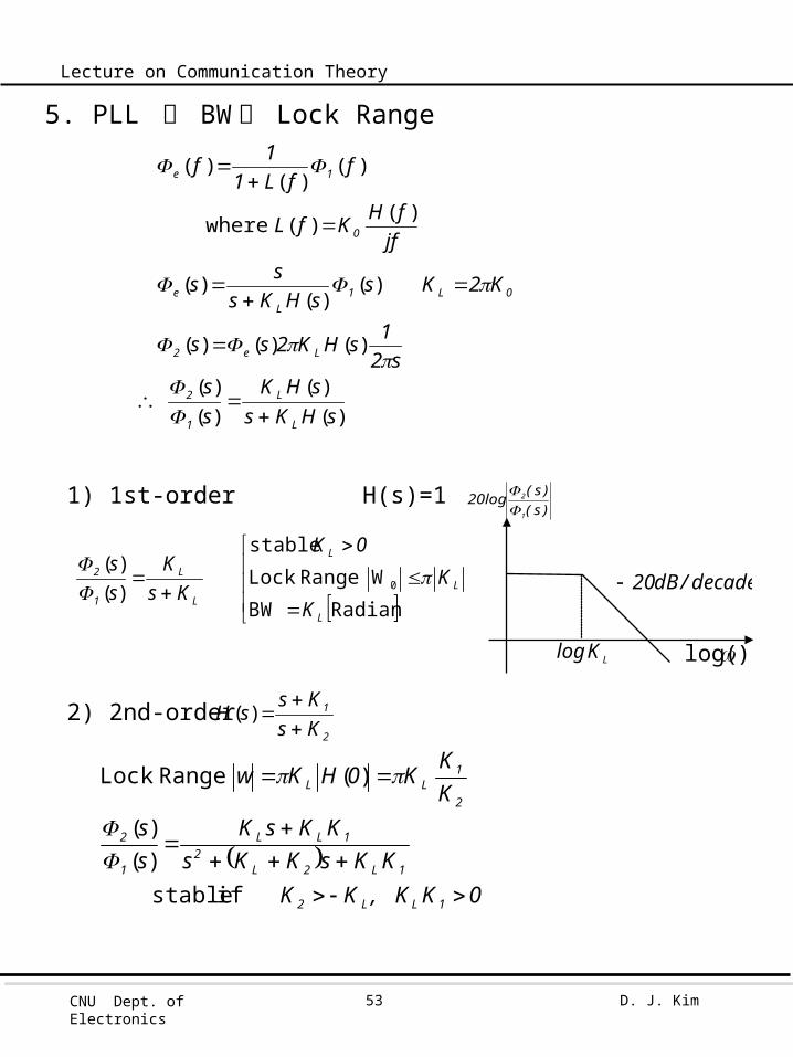
5. PLL 의 BW 와 Lock Range
1) 1st-order H(s)=1
2) 2nd-order
)()(
)()(
)()()(
)()(
)(
)()(
)()(
)(
sHKssHK
ss
s21sHK2ss
K2KssHKs
ss
jffHKfL
ffL1
1f
L
L
1
2
Le2
0L1L
e
0
1e
where
RadianBW
W Range Lock
stable
0
L
L
L
L
L
1
2
K
K
0K
KsK
ss
)()(
)s()s(log20
1
2
LKlog )log(
decade/dB20
2
1
KsKs
sH
)(
0K, KKK
KKsKKsKKsK
ss
KK
K0HKw
1LL2
1L2L2
1LL
1
2
2
1LL
if stable
Range Lock
)()(
)(
CNU Dept. of Electronics
D. J. Kim54
Lecture on Communication Theory
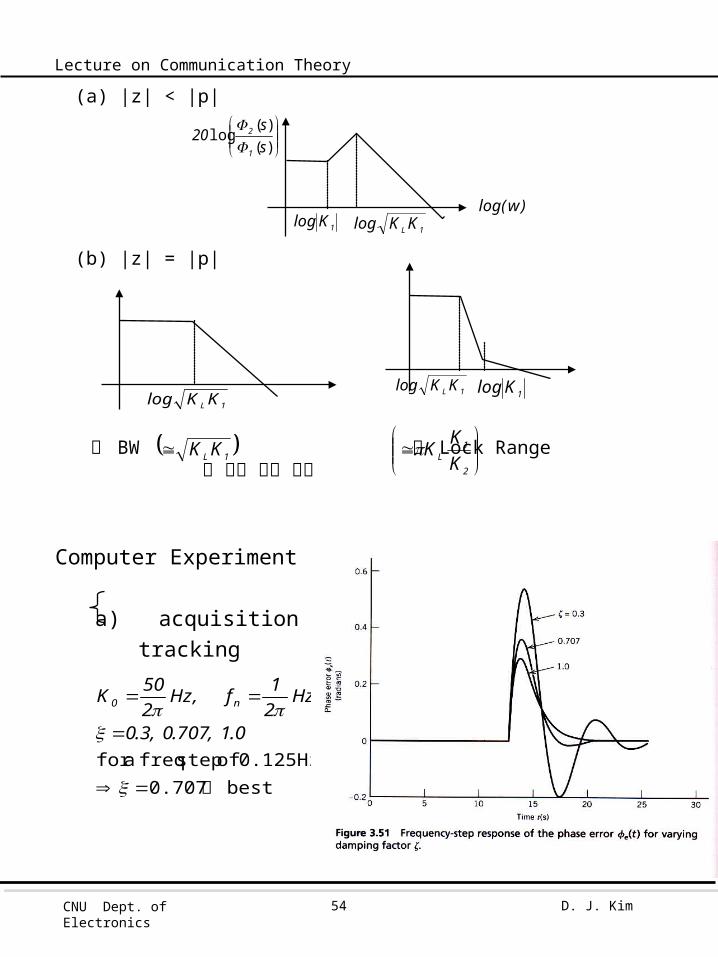
(a) |z| < |p|
(b) |z| = |p|
즉 BW 과 Lock Range 을 별도 조절 가능
Computer Experiment II Acquisition Mode
a) acquisition tracking
1L KK
2
1L K
KK
best 0.707 0.125Hz of step freq a for
이
0.1,707.0,3.0
Hz21f,Hz
250K n0
)()(
logss
201
2
)wlog(1Klog
1L KKlog
1L KKlog1L KKlog
1Klog
CNU Dept. of Electronics
D. J. Kim55
Lecture on Communication Theory
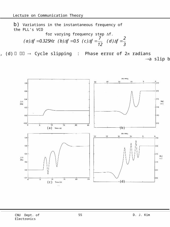
(a)
(d)(c)
(b)
32f)d(
127f)c(5.0f)b(Hz325.0f)a(
(b), (c), (d) 의 경우 Cycle slipping : Phase error of 2 radians a slip by one cycle
b) Variations in the instantaneous frequency of the PLL’s VCO for varying frequency step f.
CNU Dept. of Electronics
D. J. Kim56
Lecture on Communication Theory
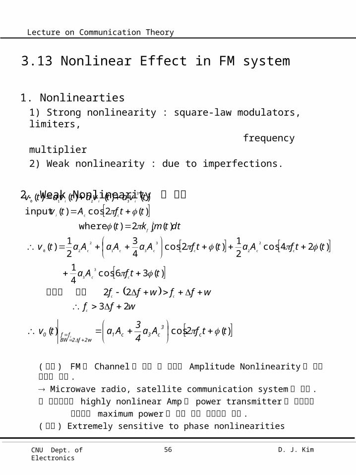
3.13 Nonlinear Effect in FM system
1. Nonlinearties1) Strong nonlinearity : square-law modulators, limiters, frequency multiplier2) Weak nonlinearity : due to imperfections.
2. Weak Nonlinearity 의 경우
( 결론 ) FM 은 Channel 로 전송 중 생기는 Amplitude Nonlinearity 에 의한 영향이 없다 . Microwave radio, satellite communication system 에 사용 .이 채널에서는 highly nonlinear Amp 와 power transmitter 를 사용한다 왜냐하면 maximum power 을 내는 것이 중요하기 때문 .( 단점 ) Extremely sensitive to phase nonlinearities
wffwffwff
ttfAa
ttfAattfAaAaAatv
dttmktttfAtvtvatvatvatv
c
cc
cc
cccccc
t
f
cci
iii
23 22
)(36cos41
)(24cos21)(2cos
43
21)(
)(2)( where
)(2cos)( input)()()()(
3
3
2
2
3
31
2
20
0
3
3210
2
조건주파수
)(cos)( ttf2Aa43Aatv c
3c3c1
w2f2BWff0 c

CNU Dept. of Electronics
D. J. Kim57
Lecture on Communication Theory
3.14. The Superheterodyne Receiver
1. Tasks of receiver1) Carrier-frequency tuning2) Filtering3) Amplification
2. Superheterodyne : RF IFDetection(Demodulation)
<HW #4> 3.28, 3.30, 3.45
757.25Mch69
11.25M
ch2 LO
Tuning Channel 44MHzIF
801.25806~800
ch69
55.2560~54
ch2 RF ;TV ex)
FRLOLORFIFfforfff
BPF1 BPF2 LPF 50~860M LO 44M
44M 55.25 - 11.25 = 44image frequency 37.25 + 11.25 = 44
IF
LO
Related Documents