Fronius Ohmpilot Operating Instructions / Battery Charging Systems / Welding Technology / Solar Electronics Accessories EN FIND YOUR OPERATING MANUALS www.fronius.com/ohmpilot-manuals FIND YOUR OPERATING MANUALS 42,0410,2141,EN 008-25012019

Welcome message from author
This document is posted to help you gain knowledge. Please leave a comment to let me know what you think about it! Share it to your friends and learn new things together.
Transcript
Fronius Ohmpilot Operating Instructions
/ Battery Charging Systems / Welding Technology / Solar Electronics
AccessoriesEN
FIND YOUR
OPERATING MANUALS
www.fronius.com/ohmpilot-manuals FIND YOUR
OPERATING MANUALS
42,0410,2141,EN 008-25012019

2
3
EN
Dear Reader,
We would like to thank you for the trust you have placed in us and congratulate you on purchasing this high-quality Fronius product. These instructions will help you to familiar-ise yourself with the product. By reading the instructions carefully, you will learn about the diverse possibilities offered by your Fronius product. Only by doing so will you be able to make the best possible use of its benefits.
Please also observe the safety rules and thereby ensure a higher level of safety at the location where the product is being used. Careful handling of your product will support its quality and reliability over its long service life. These are key prerequisites for outstand-ing results.
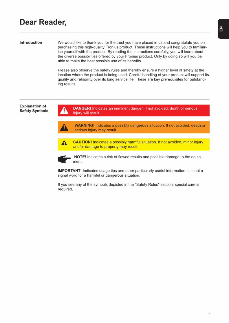
NOTE! Indicates a risk of flawed results and possible damage to the equip- ment.
IMPORTANT! Indicates usage tips and other particularly useful information. It is not a signal word for a harmful or dangerous situation.
If you see any of the symbols depicted in the "Safety Rules" section, special care is required.
Introduction
Explanation of Safety Symbols DANGER! Indicates an imminent danger. If not avoided, death or serious
injury will result.
WARNING! Indicates a possibly dangerous situation. If not avoided, death or serious injury may result.
CAUTION! Indicates a possibly harmful situation. If not avoided, minor injury and/or damage to property may result.

4
5
EN
Contents
Safety Rules .................................................................................................................................................... 7General Remarks ........................................................................................................................................ 7Environmental Conditions ........................................................................................................................... 7Choice of Location....................................................................................................................................... 8Explanation of Symbols - Installation Position............................................................................................. 9Choice of Location - General Remarks ..................................................................................................... 10Qualified Personnel ................................................................................................................................... 11EMC Measures.......................................................................................................................................... 11Final Disposal ............................................................................................................................................ 11Data Back-Up ............................................................................................................................................ 11Copyright ................................................................................................................................................... 11
General Remarks ........................................................................................................................................... 12Utilisation in Accordance with "Intended Purpose" .................................................................................... 12Warning Notices on the Device ................................................................................................................ 14
Wall Mounting ................................................................................................................................................. 15Safety ........................................................................................................................................................ 15Selecting Wall Plugs and Screws .............................................................................................................. 15Recommended Screws ............................................................................................................................. 15Installation Instructions .............................................................................................................................. 15
Fronius Smart Meter ....................................................................................................................................... 16Integrating the Fronius Smart Meter.......................................................................................................... 16
Indications/Controls on the Device ................................................................................................................. 17Selection of Heater ......................................................................................................................................... 18
1-Phase Heater ......................................................................................................................................... 183-Phase Heater ......................................................................................................................................... 18Example for Calculation of Charging Time ................................................................................................ 18
Wiring Diagram ............................................................................................................................................... 19Stripping Lengths ...................................................................................................................................... 20Electrical Connection................................................................................................................................. 20Opening the Ohmpilot ............................................................................................................................... 20
Application Example 1: 1-Phase Heating Element up to 3 kW ....................................................................... 21Application Example 2: 3-Phase Heating Element 900 W up to 9 kW ........................................................... 23Application Example 3: 1-Phase Heating Element up to 3 kW with Heat Pump Control ................................ 25Application Example 4: 1-Phase Heating Element up to 3 kW and External Source (e.g. gas-fired heating) 28Application Example 5: Two Heating Elements - 3-Phase and 1-Phase ........................................................ 31Application Example 6: Two 3-Phase Heating Elements up to 9 kW ............................................................. 34Establishing the Data Connection .................................................................................................................. 37
Possible Communication Channels........................................................................................................... 37Establishing a Connection via Modbus RTU ............................................................................................. 38Establishing a Connection via LAN ........................................................................................................... 39Establishing a Connection via WLAN ........................................................................................................ 40
Status Indication on Web Interface ................................................................................................................ 42Optional Settings ............................................................................................................................................ 43
Manual Setting HEATER 1 ........................................................................................................................ 43Activating Legionella Prevention ............................................................................................................... 43Adapting the Day Curve ............................................................................................................................ 44Temperature Limitation .............................................................................................................................. 44
Error List ......................................................................................................................................................... 45Technical Data ................................................................................................................................................ 30
Input Data .................................................................................................................................................. 47Interfaces................................................................................................................................................... 47Output Data ............................................................................................................................................... 47General Data ............................................................................................................................................. 47
Warranty Terms and Conditions, Disposal ..................................................................................................... 48Fronius Manufacturer's Warranty .............................................................................................................. 48Final Disposal ............................................................................................................................................ 48Applicable Standards and Guidelines ....................................................................................................... 48
Fronius Worldwide

6
7
EN
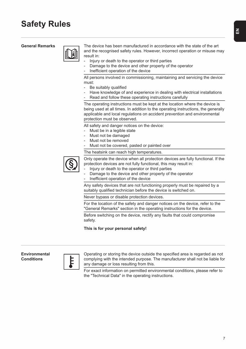
The device has been manufactured in accordance with the state of the art and the recognised safety rules. However, incorrect operation or misuse may result in: - Injury or death to the operator or third parties- Damage to the device and other property of the operator- Inefficient operation of the deviceAll persons involved in commissioning, maintaining and servicing the device must:- Be suitably qualified- Have knowledge of and experience in dealing with electrical installations- Read and follow these operating instructions carefullyThe operating instructions must be kept at the location where the device isbeing used at all times. In addition to the operating instructions, the generally applicable and local regulations on accident prevention and environmental protection must be observed.All safety and danger notices on the device:- Must be in a legible state- Must not be damaged- Must not be removed- Must not be covered, pasted or painted overThe heatsink can reach high temperatures.Only operate the device when all protection devices are fully functional. If the protection devices are not fully functional, this may result in:- Injury or death to the operator or third parties- Damage to the device and other property of the operator- Inefficient operation of the deviceAny safety devices that are not functioning properly must be repaired by a suitably qualified technician before the device is switched on.Never bypass or disable protection devices.For the location of the safety and danger notices on the device, refer to the "General Remarks" section in the operating instructions for the device.Before switching on the device, rectify any faults that could compromise safety.
This is for your personal safety!
Operating or storing the device outside the specified area is regarded as not complying with the intended purpose. The manufacturer shall not be liable for any damage or loss resulting from this.For exact information on permitted environmental conditions, please refer to the "Technical Data" in the operating instructions.
Environmental Conditions
Safety Rules
General Remarks
8
Choice of Location
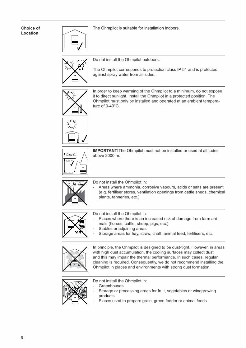
The Ohmpilot is suitable for installation indoors.
Do not install the Ohmpilot outdoors.
The Ohmpilot corresponds to protection class IP 54 and is protected against spray water from all sides.
In order to keep warming of the Ohmpilot to a minimum, do not expose it to direct sunlight. Install the Ohmpilot in a protected position. The Ohmpilot must only be installed and operated at an ambient tempera-ture of 0-40°C.
IMPORTANT!The Ohmpilot must not be installed or used at altitudes above 2000 m.
Do not install the Ohmpilot in: - Areas where ammonia, corrosive vapours, acids or salts are present (e.g. fertiliser stores, ventilation openings from cattle sheds, chemical plants, tanneries, etc.)
Do not install the Ohmpilot in:- Places where there is an increased risk of damage from farm ani-
mals (horses, cattle, sheep, pigs, etc.)- Stables or adjoining areas- Storage areas for hay, straw, chaff, animal feed, fertilisers, etc.
In principle, the Ohmpilot is designed to be dust-tight. However, in areas with high dust accumulation, the cooling surfaces may collect dust and this may impair the thermal performance. In such cases, regular cleaning is required. Consequently, we do not recommend installing the Ohmpilot in places and environments with strong dust formation.
Do not install the Ohmpilot in:- Greenhouses- Storage or processing areas for fruit, vegetables or winegrowing
products- Places used to prepare grain, green fodder or animal feeds
9
EN
Explanation of Symbols - Installation Position
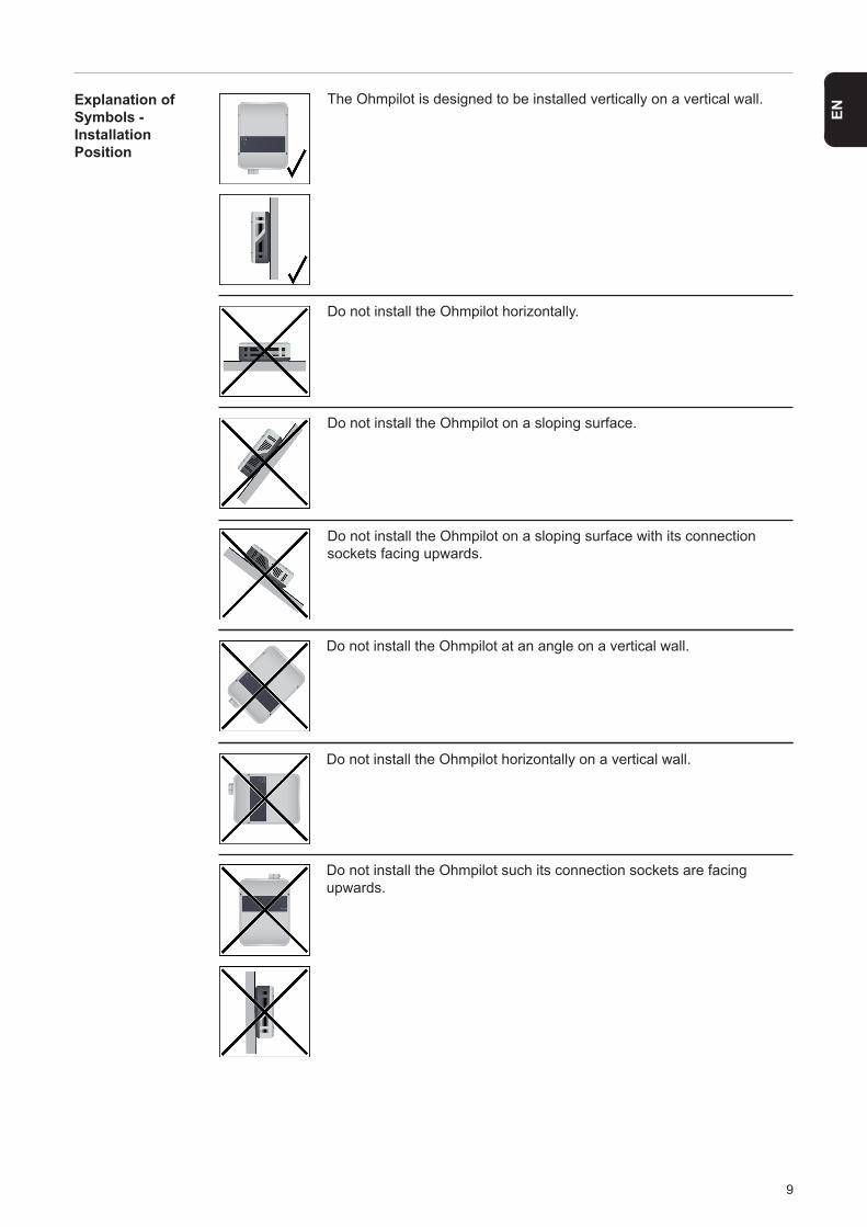
The Ohmpilot is designed to be installed vertically on a vertical wall.
Do not install the Ohmpilot horizontally.
Do not install the Ohmpilot on a sloping surface.
Do not install the Ohmpilot on a sloping surface with its connection sockets facing upwards.
Do not install the Ohmpilot at an angle on a vertical wall.
Do not install the Ohmpilot horizontally on a vertical wall.
Do not install the Ohmpilot such its connection sockets are facingupwards.
10
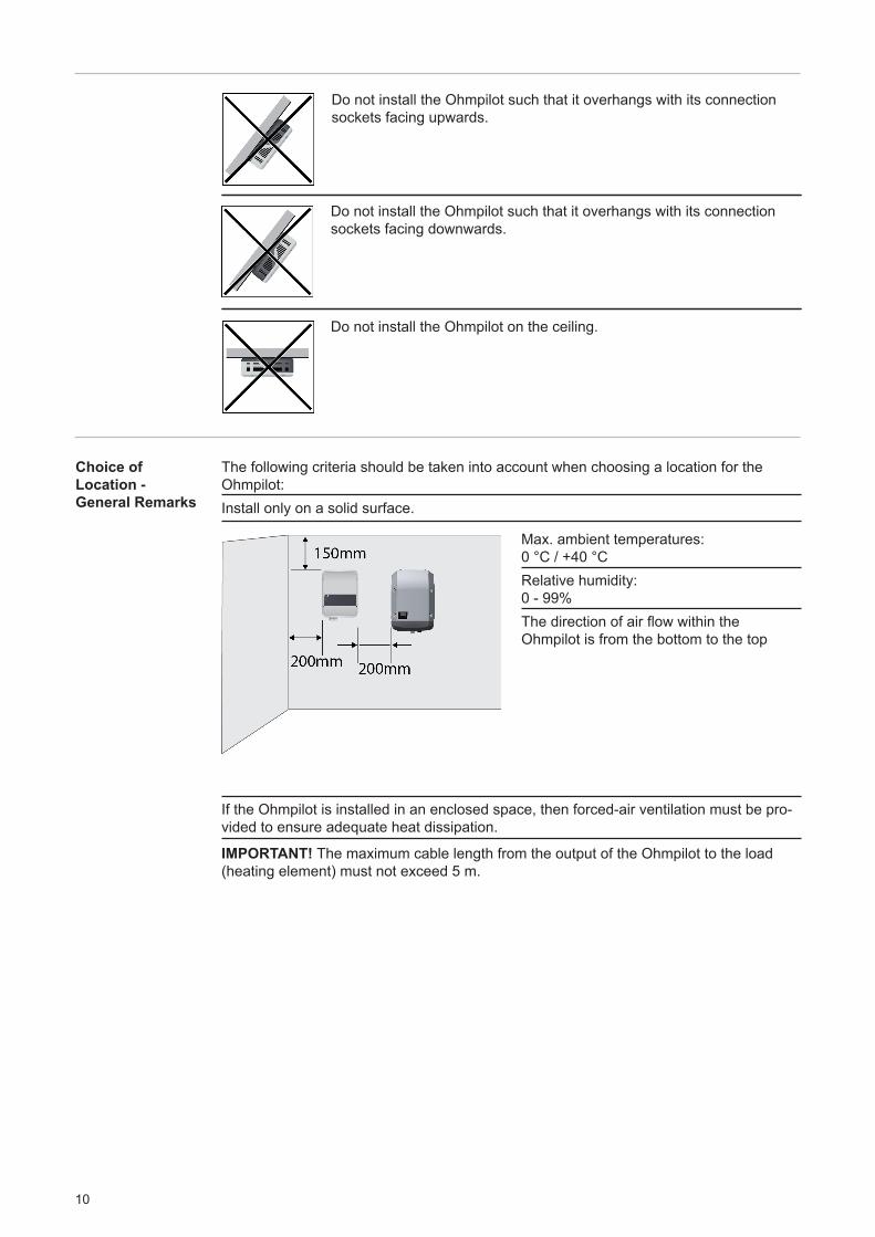
Do not install the Ohmpilot such that it overhangs with its connection sockets facing upwards.
Do not install the Ohmpilot such that it overhangs with its connection sockets facing downwards.
The following criteria should be taken into account when choosing a location for the Ohmpilot:Install only on a solid surface.
If the Ohmpilot is installed in an enclosed space, then forced-air ventilation must be pro-vided to ensure adequate heat dissipation.
IMPORTANT! The maximum cable length from the output of the Ohmpilot to the load (heating element) must not exceed 5 m.
Max. ambient temperatures:0 °C / +40 °CRelative humidity:0 - 99%The direction of air flow within theOhmpilot is from the bottom to the top
Do not install the Ohmpilot on the ceiling.
Choice of Location - General Remarks
11
EN
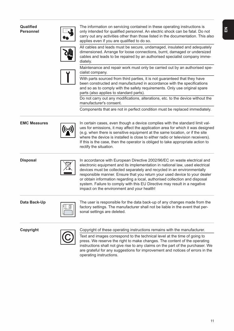
The information on servicing contained in these operating instructions is only intended for qualified personnel. An electric shock can be fatal. Do not carry out any activities other than those listed in the documentation. This also applies even if you are qualified to do so. All cables and leads must be secure, undamaged, insulated and adequately dimensioned. Arrange for loose connections, burnt, damaged or undersized cables and leads to be repaired by an authorised specialist company imme-diately.Maintenance and repair work must only be carried out by an authorised spe-cialist company.With parts sourced from third parties, it is not guaranteed that they have been constructed and manufactured in accordance with the specifications and so as to comply with the safety requirements. Only use original spare parts (also applies to standard parts).Do not carry out any modifications, alterations, etc. to the device without the manufacturer's consent.Components that are not in perfect condition must be replaced immediately.
In certain cases, even though a device complies with the standard limit val-ues for emissions, it may affect the application area for which it was designed (e.g. when there is sensitive equipment at the same location, or if the site where the device is installed is close to either radio or television receivers). If this is the case, then the operator is obliged to take appropriate action to rectify the situation.
In accordance with European Directive 2002/96/EC on waste electrical and electronic equipment and its implementation in national law, used electrical devices must be collected separately and recycled in an environmentally responsible manner. Ensure that you return your used device to your dealer or obtain information regarding a local, authorised collection and disposal system. Failure to comply with this EU Directive may result in a negative impact on the environment and your health!
The user is responsible for the data back-up of any changes made from the factory settings. The manufacturer shall not be liable in the event that per-sonal settings are deleted.
Copyright of these operating instructions remains with the manufacturer. Text and images correspond to the technical level at the time of going to press. We reserve the right to make changes. The content of the operating instructions shall not give rise to any claims on the part of the purchaser. We are grateful for any suggestions for improvement and notices of errors in the operating instructions.
QualifiedPersonnel
EMC Measures
Disposal
Data Back-Up
Copyright
12
With its "24 hours of sun" vision, Fronius is aiming to offer its customers solutions for generating, storing, distributing and using energy in an intelligent and cost efficient man-ner. The use of surplus energy for hot water preparation constitutes a simple option, with low investment costs, for storing electricity in the form of heat and using it at a time of the customer’s choosing.
The Fronius Ohmpilot, which carries out precisely this task, is therefore an ideal addition to the Fronius product portfolio in the area of energy management and a further step towards "24 hours of sun".
The solution as a whole consists of the following components:
• Fronius Symo / Galvo / Eco or Primo inverter (from Fronius Datamanager 2.0 software version 3.8.1-x onwards)• Fronius Smart Meter• Fronius Ohmpilot• Resistive loads (e.g. boiler with heating element)
NOTE! As of software version 3.13.1-x of the Fronius Datamanager or 1.11.1-x of the Hybridmanager, the Ohmpilot can be used together with the dynamic power limitation of 0-100%.
NOTE! With the Fronius Datamanager Box 2.0, it is also possible to use any other generation source (CHP unit, non-Fronius inverter, etc.). However, as the figures for power produced and consumption are not available for these options, they cannot be displayed in Solarweb.
NOTE! In an emergency situation, the Ohmpilot cannot be operated due to its high-power consumption. It is recommended that the Ohmpilot be installed outside of the emergency power system. If the Ohmpilot is installed in the emergency power system, the circuit breaker of the Ohmpilot must be switched off in the event of a power failure. Alternatively, if there is no circuit break, the heating element measurement must be switched to manual and the minimum temperature and legionella protection must be deactivated. (See the “Optional Settings” chapter). The power required for these functions exceeds the power limits of an emergency power supply, therefore, the emergency power opera- tion cannot start. These settings can no longer be made during a power failure.
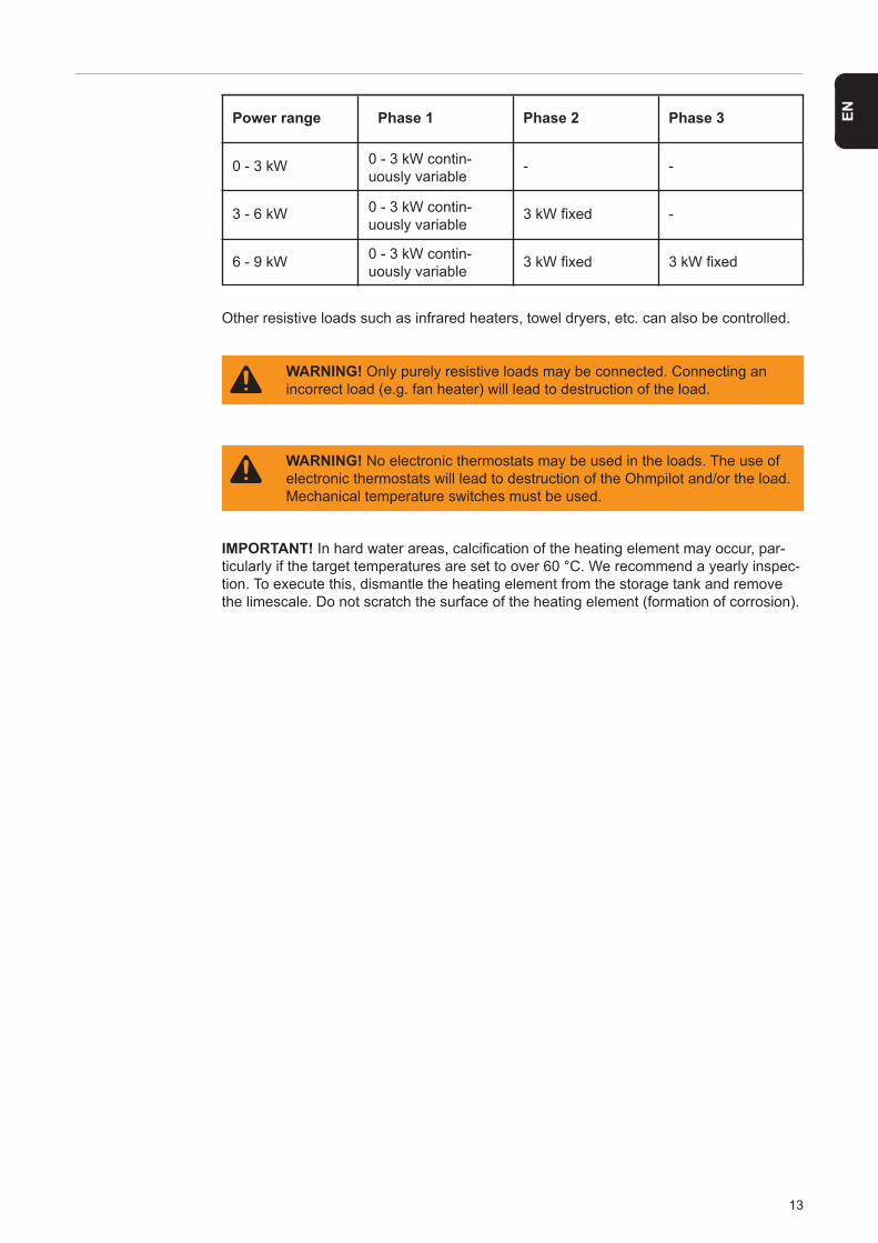
The Ohmpilot is a separate device that can control the surplus power from the photovol-taic system in a continuously variable manner, using pulse width modulation, for a phase between 0 and 100% (or 0 and 3 kW). Moreover, the Ohmpilot has two additional outputs for switching further phases. As a result, heating elements with an output of between 300 W and 9 kW can be controlled in a continuously variable manner:
A heating element with up to 3 kW output can be controlled in a continuously variable manner using one phase.
In the case of a heating element with 9 kW output, the surplus power of 0 - 3 kW is controlled in a continuously variable manner in phase 1. If more power is available, the Ohmpilot activates phase 2 in addition and phase 1 can again control the surplus in a continuously variable manner between 3 - 6 kW. If the available power is greater than 6 kW, the Ohmpilot adds phase 3 and phase 1 again controls the surplus between 6 and 9 kW in a continuously variable manner.
General Remarks
Proper Use / Intended Purpose
13
EN
Other resistive loads such as infrared heaters, towel dryers, etc. can also be controlled.
IMPORTANT! In hard water areas, calcification of the heating element may occur, par-ticularly if the target temperatures are set to over 60 °C. We recommend a yearly inspec-tion. To execute this, dismantle the heating element from the storage tank and remove the limescale. Do not scratch the surface of the heating element (formation of corrosion).
Power range
0 - 3 kW
3 - 6 kW
6 - 9 kW
Phase 1
0 - 3 kW contin-uously variable
Phase 2
-
3 kW fixed
3 kW fixed
Phase 3
-
-
3 kW fixed
WARNING! No electronic thermostats may be used in the loads. The use of electronic thermostats will lead to destruction of the Ohmpilot and/or the load. Mechanical temperature switches must be used.
WARNING! Only purely resistive loads may be connected. Connecting an incorrect load (e.g. fan heater) will lead to destruction of the load.
0 - 3 kW contin-uously variable
0 - 3 kW contin-uously variable
14
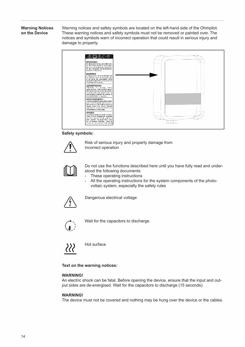
Warning notices and safety symbols are located on the left-hand side of the Ohmpilot. These warning notices and safety symbols must not be removed or painted over. The notices and symbols warn of incorrect operation that could result in serious injury and damage to property.
Risk of serious injury and property damage from incorrect operation
Dangerous electrical voltage
Wait for the capacitors to discharge.
Hot surface
Do not use the functions described here until you have fully read and under-stood the following documents: - These operating instructions- All the operating instructions for the system components of the photo- voltaic system, especially the safety rules
Warning Notices on the Device
Safety symbols:
Text on the warning notices:
WARNING! An electric shock can be fatal. Before opening the device, ensure that the input and out-put sides are de-energised. Wait for the capacitors to discharge (15 seconds).
WARNING! The device must not be covered and nothing may be hung over the device or the cables.
15
EN
Wall Mounting
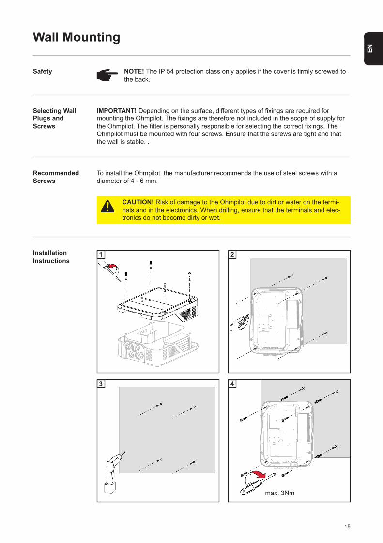
NOTE! The IP 54 protection class only applies if the cover is firmly screwed to the back.
IMPORTANT! Depending on the surface, different types of fixings are required for mounting the Ohmpilot. The fixings are therefore not included in the scope of supply for the Ohmpilot. The fitter is personally responsible for selecting the correct fixings. The Ohmpilot must be mounted with four screws. Ensure that the screws are tight and that the wall is stable. .
To install the Ohmpilot, the manufacturer recommends the use of steel screws with a diameter of 4 - 6 mm.
Safety
Selecting Wall Plugs and Screws
Recommended Screws
Installation Instructions
CAUTION! Risk of damage to the Ohmpilot due to dirt or water on the termi-nals and in the electronics. When drilling, ensure that the terminals and elec-tronics do not become dirty or wet.
1 2
3 4
max. 3Nm
16
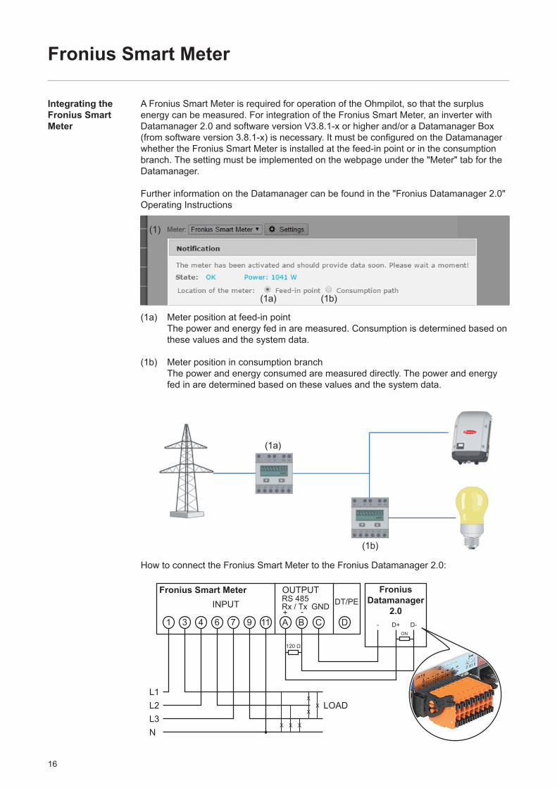
How to connect the Fronius Smart Meter to the Fronius Datamanager 2.0:
Fronius Smart Meter
A Fronius Smart Meter is required for operation of the Ohmpilot, so that the surplus energy can be measured. For integration of the Fronius Smart Meter, an inverter with Datamanager 2.0 and software version V3.8.1-x or higher and/or a Datamanager Box (from software version 3.8.1-x) is necessary. It must be configured on the Datamanager whether the Fronius Smart Meter is installed at the feed-in point or in the consumption branch. The setting must be implemented on the webpage under the "Meter" tab for the Datamanager.
Further information on the Datamanager can be found in the "Fronius Datamanager 2.0" Operating Instructions
(1a) Meter position at feed-in point The power and energy fed in are measured. Consumption is determined based on these values and the system data.
(1b) Meter position in consumption branch The power and energy consumed are measured directly. The power and energy fed in are determined based on these values and the system data.
Integrating the Fronius Smart Meter
(1a)
(1a)
(1b)
(1)
(1b)
Fronius Smart MeterINPUT
L1L2L3N
OUTPUTRS 485 DT/PERx / x GND
1 A B C D3 4 6 7 9 11
LOAD
X X X
X
XX
+T-
Fronius Datamanager
2.0
120 Ω
ON
- D+ D-

17
EN
Indications/Controls on the Device
1x WPS2x ACCESS POINT3x BOOST
WPS (Wi-Fi Protected Setup) is opened for 2 minutes or until successful pairing with the router. By pressing the WPS button the router, the WLAN password is transmitted to the Ohmpilot.
WLAN access point is activated for 30 minutes so that settings can be implement-ed on the Ohmpilot via the Fronius Solar web app.
Boost mode - dimmer level is activated for 4 hours at 100%, L2 and L3 are switched through. This may result in electricity being sourced from the grid.
Ohmpilot is returned to standard operating mode, boost mode, access point or WPS are deactivated.
No power supply to the Ohmpilot The faster the flashing frequency, the greater the heat output. At 0 W heat output the LED flashes slowly, at full output it flashes quickly.The output from the heating element is measured and it is detected whether a 1-phase or 3-phase heating element is connected. Target temperature undercut or legionella prevention system active (full heat output).
No connection WPS (Wi-Fi Protected Setup) open WLAN access point open Connection with network
No errorNo connection to the inverterTemperature measurement faultyHeating element faultyOhmpilot faulty Target temperature not reached
Press 1x
Press 2x
Press 3x
Press again
Unlit
Flashing green
Flashing green 2x
Steady green
Heater indication
Green LED
UnlitFlashing blue 1xFlashing blue 2xSteady blue
Connection indica-tion LAN / WLAN
Blue LED
UnlitFlashing red 1xFlashing red 2xFlashing red 3xFlashing red 4xFlashing red 5x
Error indicationRed LED
A detailed description of the error is provided in Solar Web.
18
Selection of Heater
- 0.3 to 3 kW
NOTE! It will be regulated continuously between 0-3kW
- Purely resistive load (no electronic temperature limiters, fans, etc.)
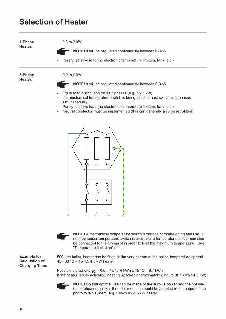
- 0.9 to 9 kW
NOTE! It will be regulated continuously between 0-9kW
- Equal load distribution on all 3 phases (e.g. 3 x 3 kW)- If a mechanical temperature switch is being used, it must switch all 3 phases simultaneously.- Purely resistive load (no electronic temperature limiters, fans, etc.)- Neutral conductor must be implemented (this can generally also be retrofitted)
1-PhaseHeater:
3-PhaseHeater:
NOTE! A mechanical temperature switch simplifies commissioning and use. If no mechanical temperature switch is available, a temperature sensor can also be connected to the Ohmpilot in order to limit the maximum temperature. (See "Temperature limitation")
500-litre boiler, heater can be fitted at the very bottom of the boiler, temperature spread 45 - 60 °C = 15 °C; 4.5 kW heater
Possible stored energy = 0.5 m³ x 1.16 kWh x 15 °C = 8.7 kWhIf the heater is fully activated, heating up takes approximately 2 hours (8.7 kWh / 4.5 kW)
NOTE! So that optimal use can be made of the surplus power and the hot wa-ter is reheated quickly, the heater output should be adapted to the output of the photovoltaic system, e.g. 5 kWp => 4.5 kW heater.
Example for Calculation of Charging Time:
19
EN
Wiring Diagram
NC W NOOUT NL1 L2 L2L3 N N L3 N
LAN RS
485
PT1
000
D+ D- -
R2 R3
G B R1 2 3
4
5 7
8 9 10 11 12
6
7
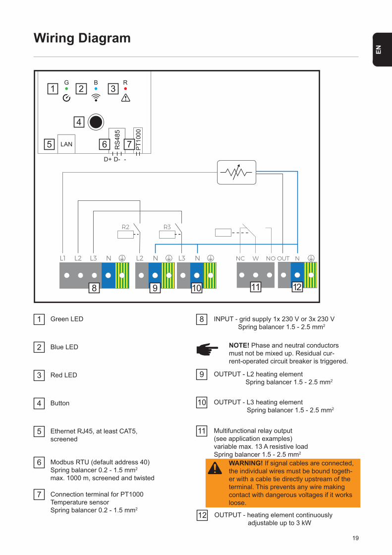
1 Green LED
Connection terminal for PT1000 Temperature sensorSpring balancer 0.2 - 1.5 mm2
8
2 Blue LED
INPUT - grid supply 1x 230 V or 3x 230 V Spring balancer 1.5 - 2.5 mm2
3 Red LED
4 Button
5 Ethernet RJ45, at least CAT5, screened
6 Modbus RTU (default address 40)Spring balancer 0.2 - 1.5 mm2
max. 1000 m, screened and twisted
9 OUTPUT - L2 heating element Spring balancer 1.5 - 2.5 mm2
10 OUTPUT - L3 heating element Spring balancer 1.5 - 2.5 mm2
11 Multifunctional relay output(see application examples) variable max. 13 A resistive loadSpring balancer 1.5 - 2.5 mm2
WARNING! If signal cables are connected, the individual wires must be bound togeth-er with a cable tie directly upstream of the terminal. This prevents any wire making contact with dangerous voltages if it works loose.
12 OUTPUT - heating element continuously adjustable up to 3 kW
NOTE! Phase and neutral conductors must not be mixed up. Residual cur- rent-operated circuit breaker is triggered.
20
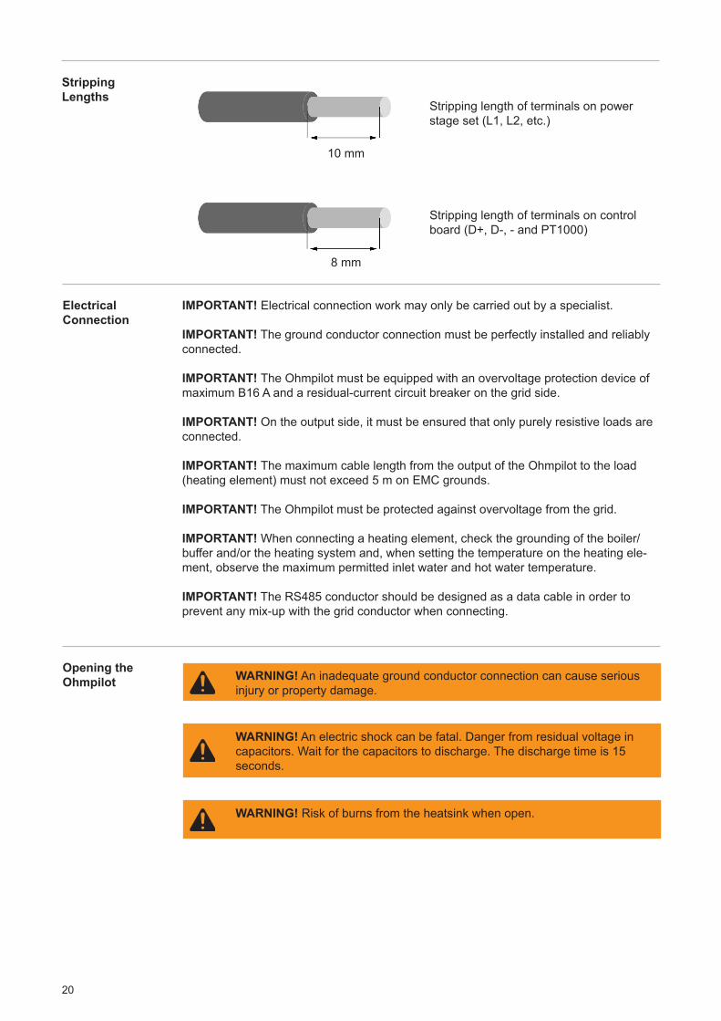
Stripping length of terminals on power stage set (L1, L2, etc.)
10 mm
8 mm
Stripping length of terminals on control board (D+, D-, - and PT1000)
Stripping Lengths
Electrical Connection
Opening the Ohmpilot
IMPORTANT! Electrical connection work may only be carried out by a specialist.
IMPORTANT! The ground conductor connection must be perfectly installed and reliably connected.
IMPORTANT! The Ohmpilot must be equipped with an overvoltage protection device of maximum B16 A and a residual-current circuit breaker on the grid side.
IMPORTANT! On the output side, it must be ensured that only purely resistive loads are connected.
IMPORTANT! The maximum cable length from the output of the Ohmpilot to the load (heating element) must not exceed 5 m on EMC grounds.
IMPORTANT! The Ohmpilot must be protected against overvoltage from the grid.
IMPORTANT! When connecting a heating element, check the grounding of the boiler/buffer and/or the heating system and, when setting the temperature on the heating ele-ment, observe the maximum permitted inlet water and hot water temperature.
IMPORTANT! The RS485 conductor should be designed as a data cable in order to prevent any mix-up with the grid conductor when connecting.
WARNING! An electric shock can be fatal. Danger from residual voltage in capacitors. Wait for the capacitors to discharge. The discharge time is 15 seconds.
WARNING! An inadequate ground conductor connection can cause serious injury or property damage.
WARNING! Risk of burns from the heatsink when open.
21
EN
L1 L2 L2L3 N N L3 N
LAN RS
485
PT1
000
D+D- -
R2 R3
G B R
NC W NO OUT N
1
6
3
4
2
9 97 8
5
1 3 5 7
2 4 6 8
1
2
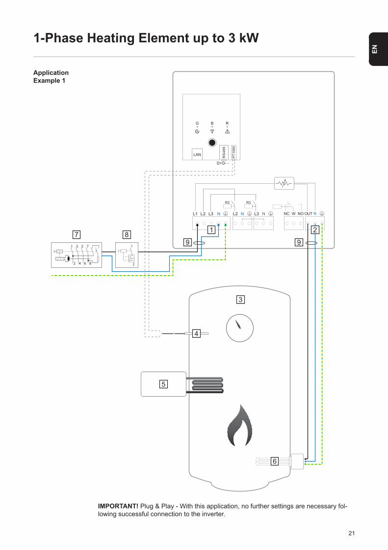
IMPORTANT! Plug & Play - With this application, no further settings are necessary fol-lowing successful connection to the inverter.
1-Phase Heating Element up to 3 kW
Application Example 1

22
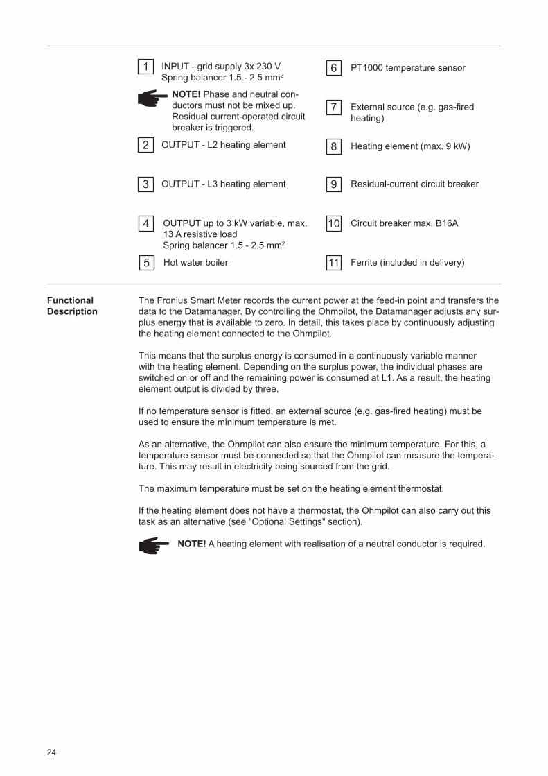
1 INPUT - grid supply 1x 230 VSpring balancer 1.5 - 2.5 mm2
NOTE! Phase and neutral con-ductors must not be mixed up. Residual current-operated circuit breaker is triggered.
2 OUTPUT up to 3 kW variable, max.13 A resistive loadSpring balancer 1.5 - 2.5 mm2
3 Hot water boiler
4 PT1000 temperature sensor
8
9
Circuit breaker max. B16A
Ferrite (included in delivery)
5 External source (e.g. gas-fired heating)
6
7
Heating element (max. 3 kW)
Residual-current circuit breaker
Functional Description
The Fronius Smart Meter records the current power at the feed-in point and transfers the data to the Datamanager. By controlling the Ohmpilot, the Datamanager adjusts any sur-plus energy that is available to zero. In detail, this takes place by continuously adjusting the heating element connected to the Ohmpilot.
This means that the surplus energy is used up by the heating element in a continuously variable manner.
If no temperature sensor is fitted, an external source (e.g. gas-fired heating) must be used to ensure the minimum temperature is met.
As an alternative, the Ohmpilot can also ensure the minimum temperature. For this, a temperature sensor must be connected so that the Ohmpilot can measure the tempera-ture. This may result in electricity being sourced from the grid.
The maximum temperature must be set on the heating element thermostat.
If the heating element does not have a thermostat, the Ohmpilot can also carry out this task as an alternative (see "Optional Settings" section).
23
EN
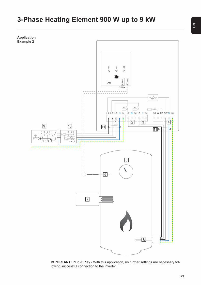
3-Phase Heating Element 900 W up to 9 kW
Application Example 2
IMPORTANT! Plug & Play - With this application, no further settings are necessary fol-lowing successful connection to the inverter.
L1 L2 L2L3 N N L3 N
LAN RS
485
PT1
000
D+D- -
R2 R3
G B R
NC W NO OUT N
5
7
8
1 32 4
6
119 101 3 5 7
2 4 6 8
111
2
3
4
5
6
24
1 INPUT - grid supply 3x 230 VSpring balancer 1.5 - 2.5 mm2
NOTE! Phase and neutral con-ductors must not be mixed up. Residual current-operated circuit breaker is triggered.
2 OUTPUT - L2 heating element
3 OUTPUT - L3 heating element
5
4
Hot water boiler
OUTPUT up to 3 kW variable, max. 13 A resistive loadSpring balancer 1.5 - 2.5 mm2
6 PT1000 temperature sensor
7
8
9
10
11
External source (e.g. gas-fired heating)
Heating element (max. 9 kW)
Residual-current circuit breaker
Circuit breaker max. B16A
Ferrite (included in delivery)
Functional Description
The Fronius Smart Meter records the current power at the feed-in point and transfers the data to the Datamanager. By controlling the Ohmpilot, the Datamanager adjusts any sur-plus energy that is available to zero. In detail, this takes place by continuously adjusting the heating element connected to the Ohmpilot.
This means that the surplus energy is consumed in a continuously variable manner with the heating element. Depending on the surplus power, the individual phases are switched on or off and the remaining power is consumed at L1. As a result, the heating element output is divided by three.
If no temperature sensor is fitted, an external source (e.g. gas-fired heating) must be used to ensure the minimum temperature is met.
As an alternative, the Ohmpilot can also ensure the minimum temperature. For this, a temperature sensor must be connected so that the Ohmpilot can measure the tempera-ture. This may result in electricity being sourced from the grid.
The maximum temperature must be set on the heating element thermostat.
If the heating element does not have a thermostat, the Ohmpilot can also carry out this task as an alternative (see "Optional Settings" section).
NOTE! A heating element with realisation of a neutral conductor is required.
25
EN
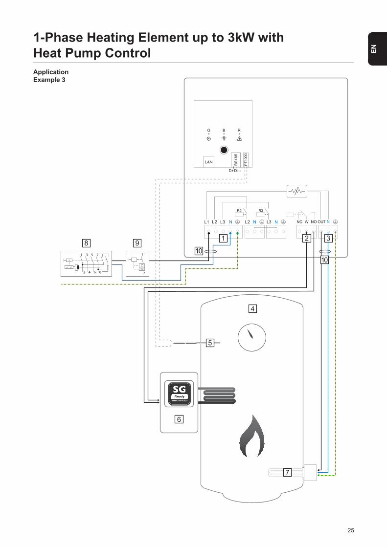
1-Phase Heating Element up to 3kW with Heat Pump ControlApplication Example 3
L1 L2 L2L3 N N L3 N
LAN RS
485
PT1
000
D+D- -
R2 R3
G B R
NC W NO OUT N
1
7
4
6
5
32
108 9
1 3 5 7
2 4 6 8
1
2
10
26
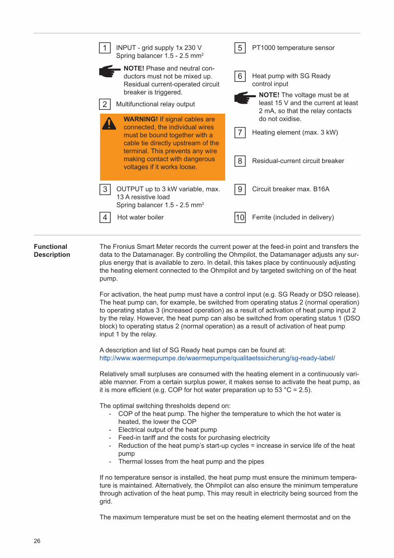
1 INPUT - grid supply 1x 230 VSpring balancer 1.5 - 2.5 mm2
NOTE! Phase and neutral con-ductors must not be mixed up. Residual current-operated circuit breaker is triggered.
WARNING! If signal cables are connected, the individual wires must be bound together with a cable tie directly upstream of the terminal. This prevents any wire making contact with dangerous voltages if it works loose.
2 Multifunctional relay output
3 OUTPUT up to 3 kW variable, max. 13 A resistive loadSpring balancer 1.5 - 2.5 mm2
NOTE! The voltage must be at least 15 V and the current at least 2 mA, so that the relay contacts do not oxidise.
4 Hot water boiler
5 PT1000 temperature sensor
6
7
8
9
10
Heat pump with SG Readycontrol input
Heating element (max. 3 kW)
Residual-current circuit breaker
Circuit breaker max. B16A
Ferrite (included in delivery)
Functional Description
The Fronius Smart Meter records the current power at the feed-in point and transfers the data to the Datamanager. By controlling the Ohmpilot, the Datamanager adjusts any sur-plus energy that is available to zero. In detail, this takes place by continuously adjusting the heating element connected to the Ohmpilot and by targeted switching on of the heat pump.
For activation, the heat pump must have a control input (e.g. SG Ready or DSO release). The heat pump can, for example, be switched from operating status 2 (normal operation) to operating status 3 (increased operation) as a result of activation of heat pump input 2 by the relay. However, the heat pump can also be switched from operating status 1 (DSO block) to operating status 2 (normal operation) as a result of activation of heat pump input 1 by the relay.
A description and list of SG Ready heat pumps can be found at:http://www.waermepumpe.de/waermepumpe/qualitaetssicherung/sg-ready-label/
Relatively small surpluses are consumed with the heating element in a continuously vari-able manner. From a certain surplus power, it makes sense to activate the heat pump, as it is more efficient (e.g. COP for hot water preparation up to 53 °C = 2.5).
The optimal switching thresholds depend on: - COP of the heat pump. The higher the temperature to which the hot water is heated, the lower the COP - Electrical output of the heat pump - Feed-in tariff and the costs for purchasing electricity - Reduction of the heat pump’s start-up cycles = increase in service life of the heat pump - Thermal losses from the heat pump and the pipes
If no temperature sensor is installed, the heat pump must ensure the minimum tempera-ture is maintained. Alternatively, the Ohmpilot can also ensure the minimum temperature through activation of the heat pump. This may result in electricity being sourced from the grid.
The maximum temperature must be set on the heating element thermostat and on the
27
EN
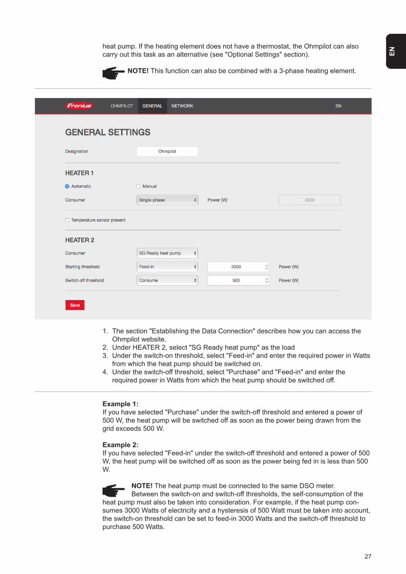
1. The section "Establishing the Data Connection" describes how you can access the Ohmpilot website.2. Under HEATER 2, select "SG Ready heat pump" as the load3. Under the switch-on threshold, select "Feed-in" and enter the required power in Watts from which the heat pump should be switched on.4. Under the switch-off threshold, select "Purchase" and "Feed-in" and enter the required power in Watts from which the heat pump should be switched off.
Example 1: If you have selected "Purchase" under the switch-off threshold and entered a power of 500 W, the heat pump will be switched off as soon as the power being drawn from the grid exceeds 500 W.
Example 2: If you have selected "Feed-in" under the switch-off threshold and entered a power of 500 W, the heat pump will be switched off as soon as the power being fed in is less than 500 W.
NOTE! The heat pump must be connected to the same DSO meter. Between the switch-on and switch-off thresholds, the self-consumption of the heat pump must also be taken into consideration. For example, if the heat pump con-sumes 3000 Watts of electricity and a hysteresis of 500 Watt must be taken into account, the switch-on threshold can be set to feed-in 3000 Watts and the switch-off threshold to purchase 500 Watts.
heat pump. If the heating element does not have a thermostat, the Ohmpilot can also carry out this task as an alternative (see "Optional Settings" section).
NOTE! This function can also be combined with a 3-phase heating element.
28
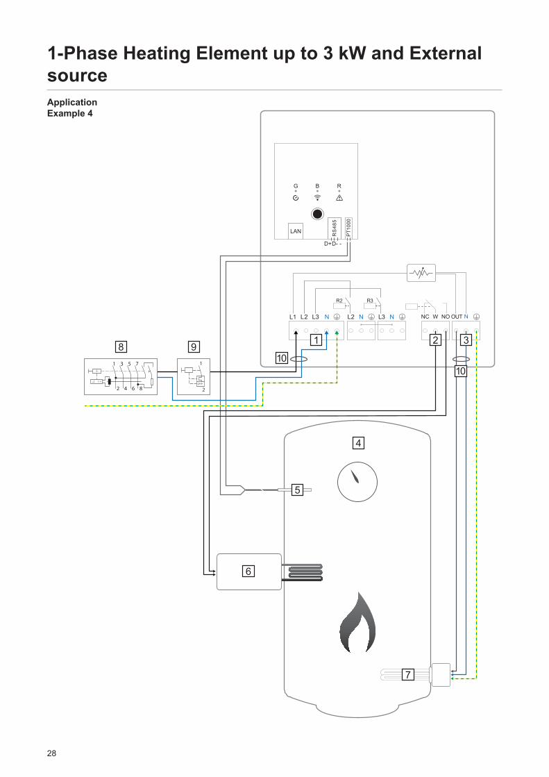
1-Phase Heating Element up to 3 kW and External sourceApplication Example 4
L1 L2 L2L3 N N L3 N
LAN RS
485
PT1
000
D+D- -
R2 R3
G B R
NC W NO OUT N
7
1 2
4
3
6
5
108 9
101 3 5 7
2 4 6 8
1
2
29
EN
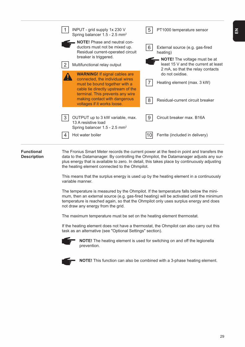
Functional Description
The Fronius Smart Meter records the current power at the feed-in point and transfers the data to the Datamanager. By controlling the Ohmpilot, the Datamanager adjusts any sur-plus energy that is available to zero. In detail, this takes place by continuously adjusting the heating element connected to the Ohmpilot.
This means that the surplus energy is used up by the heating element in a continuously variable manner.
The temperature is measured by the Ohmpilot. If the temperature falls below the mini-mum, then an external source (e.g. gas-fired heating) will be activated until the minimum temperature is reached again, so that the Ohmpilot only uses surplus energy and does not draw any energy from the grid.
The maximum temperature must be set on the heating element thermostat.
If the heating element does not have a thermostat, the Ohmpilot can also carry out this task as an alternative (see "Optional Settings" section).
NOTE! The heating element is used for switching on and off the legionella prevention.
NOTE! This function can also be combined with a 3-phase heating element.
1 INPUT - grid supply 1x 230 VSpring balancer 1.5 - 2.5 mm2
NOTE! Phase and neutral con-ductors must not be mixed up. Residual current-operated circuit breaker is triggered.
WARNING! If signal cables are connected, the individual wires must be bound together with a cable tie directly upstream of the terminal. This prevents any wire making contact with dangerous voltages if it works loose.
2 Multifunctional relay output
3 OUTPUT up to 3 kW variable, max. 13 A resistive loadSpring balancer 1.5 - 2.5 mm2
NOTE! The voltage must be at least 15 V and the current at least 2 mA, so that the relay contacts do not oxidise.
4 Hot water boiler
5 PT1000 temperature sensor
6
7
8
9
10
External source (e.g. gas-fired heating)
Heating element (max. 3 kW)
Residual-current circuit breaker
Circuit breaker max. B16A
Ferrite (included in delivery)
30
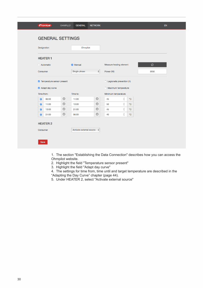
1. The section "Establishing the Data Connection" describes how you can access the Ohmpilot website.2. Highlight the field "Temperature sensor present"3. Highlight the field "Adapt day curve"4. The settings for time from, time until and target temperature are described in the “Adapting the Day Curve” chapter (page 44).5. Under HEATER 2, select "Activate external source"
31
EN
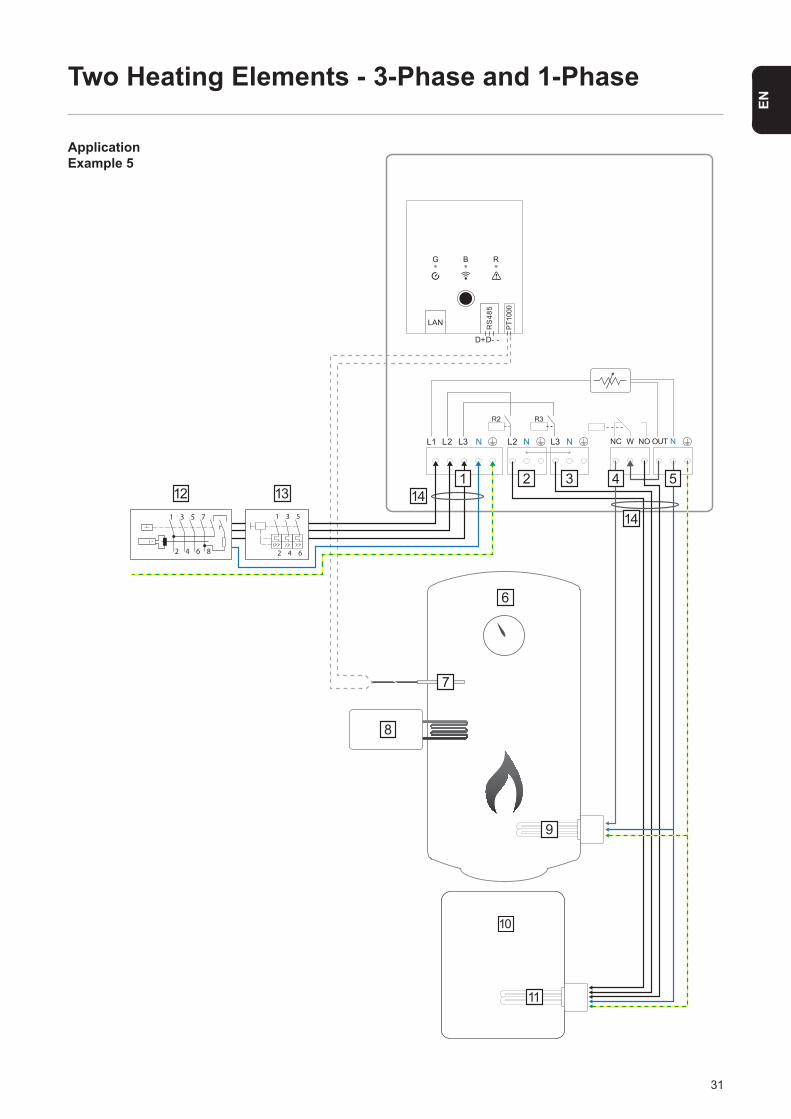
Two Heating Elements - 3-Phase and 1-Phase
Application Example 5
L1 L2 L2L3 N N L3 N
LAN RS
485
PT1
000
D+D- -
R2 R3
G B R
NC W NO OUT N
6
2 3 5
8
7
11
10
9
41412 13
1 3 5 7
2 4 6 8
1
2
3
4
5
6
1
14
32
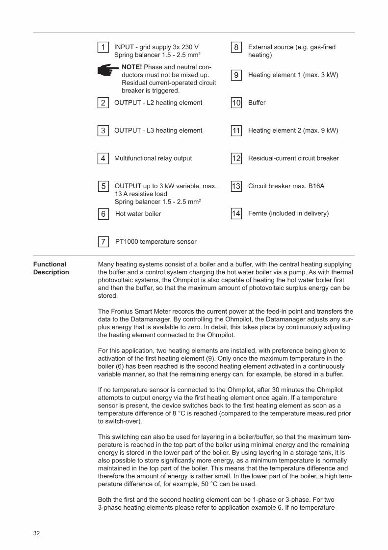
1 INPUT - grid supply 3x 230 VSpring balancer 1.5 - 2.5 mm2
NOTE! Phase and neutral con-ductors must not be mixed up. Residual current-operated circuit breaker is triggered.
2 OUTPUT - L2 heating element
3
4
5
OUTPUT - L3 heating element
Multifunctional relay output
OUTPUT up to 3 kW variable, max. 13 A resistive loadSpring balancer 1.5 - 2.5 mm2
6 Hot water boiler
7 PT1000 temperature sensor
8
9
External source (e.g. gas-fired heating)
Heating element 1 (max. 3 kW)
10
11
12
13
14
Buffer
Heating element 2 (max. 9 kW)
Residual-current circuit breaker
Circuit breaker max. B16A
Ferrite (included in delivery)
Functional Description
Many heating systems consist of a boiler and a buffer, with the central heating supplying the buffer and a control system charging the hot water boiler via a pump. As with thermal photovoltaic systems, the Ohmpilot is also capable of heating the hot water boiler first and then the buffer, so that the maximum amount of photovoltaic surplus energy can be stored.
The Fronius Smart Meter records the current power at the feed-in point and transfers the data to the Datamanager. By controlling the Ohmpilot, the Datamanager adjusts any sur-plus energy that is available to zero. In detail, this takes place by continuously adjusting the heating element connected to the Ohmpilot.
For this application, two heating elements are installed, with preference being given to activation of the first heating element (9). Only once the maximum temperature in the boiler (6) has been reached is the second heating element activated in a continuously variable manner, so that the remaining energy can, for example, be stored in a buffer.
If no temperature sensor is connected to the Ohmpilot, after 30 minutes the Ohmpilot attempts to output energy via the first heating element once again. If a temperature sensor is present, the device switches back to the first heating element as soon as a temperature difference of 8 °C is reached (compared to the temperature measured prior to switch-over).
This switching can also be used for layering in a boiler/buffer, so that the maximum tem-perature is reached in the top part of the boiler using minimal energy and the remaining energy is stored in the lower part of the boiler. By using layering in a storage tank, it is also possible to store significantly more energy, as a minimum temperature is normally maintained in the top part of the boiler. This means that the temperature difference and therefore the amount of energy is rather small. In the lower part of the boiler, a high tem-perature difference of, for example, 50 °C can be used.
Both the first and the second heating element can be 1-phase or 3-phase. For two 3-phase heating elements please refer to application example 6. If no temperature
33
EN
sensor is installed, an external source (e.g. gas-fired heating) must ensure the minimum temperature.
As an alternative, the Ohmpilot can also ensure the minimum temperature. This may re-sult in electricity being sourced from the grid. The maximum temperature must be set on the heating element thermostat. If heating element 1 (9) does not have a thermostat, the Ohmpilot can also carry out this task as an alternative (see "Optional settings" section). However, it is imperative that heating element 2 (11) has a thermostat.
NOTE! At no point can both heating elements be heated simultaneously.
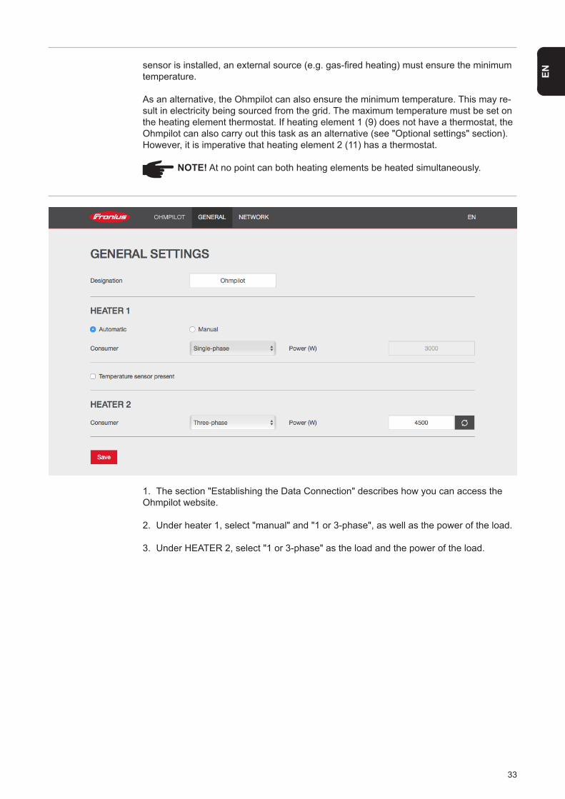
1. The section "Establishing the Data Connection" describes how you can access the Ohmpilot website.
2. Under heater 1, select "manual" and "1 or 3-phase", as well as the power of the load.
3. Under HEATER 2, select "1 or 3-phase" as the load and the power of the load.
34
L1 L2 L2L3 N N L3 N
LAN RS
485
PT1
000
D+D- -
R2 R3
G B R
NC W NO OUT N
12
11
2 3 5
6
10
8
9
7
1513 141 3 5 7
2 4 6 8
1
2
3
4
5
6
41
15
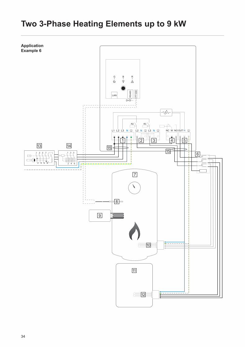
Two 3-Phase Heating Elements up to 9 kW
Application Example 6
35
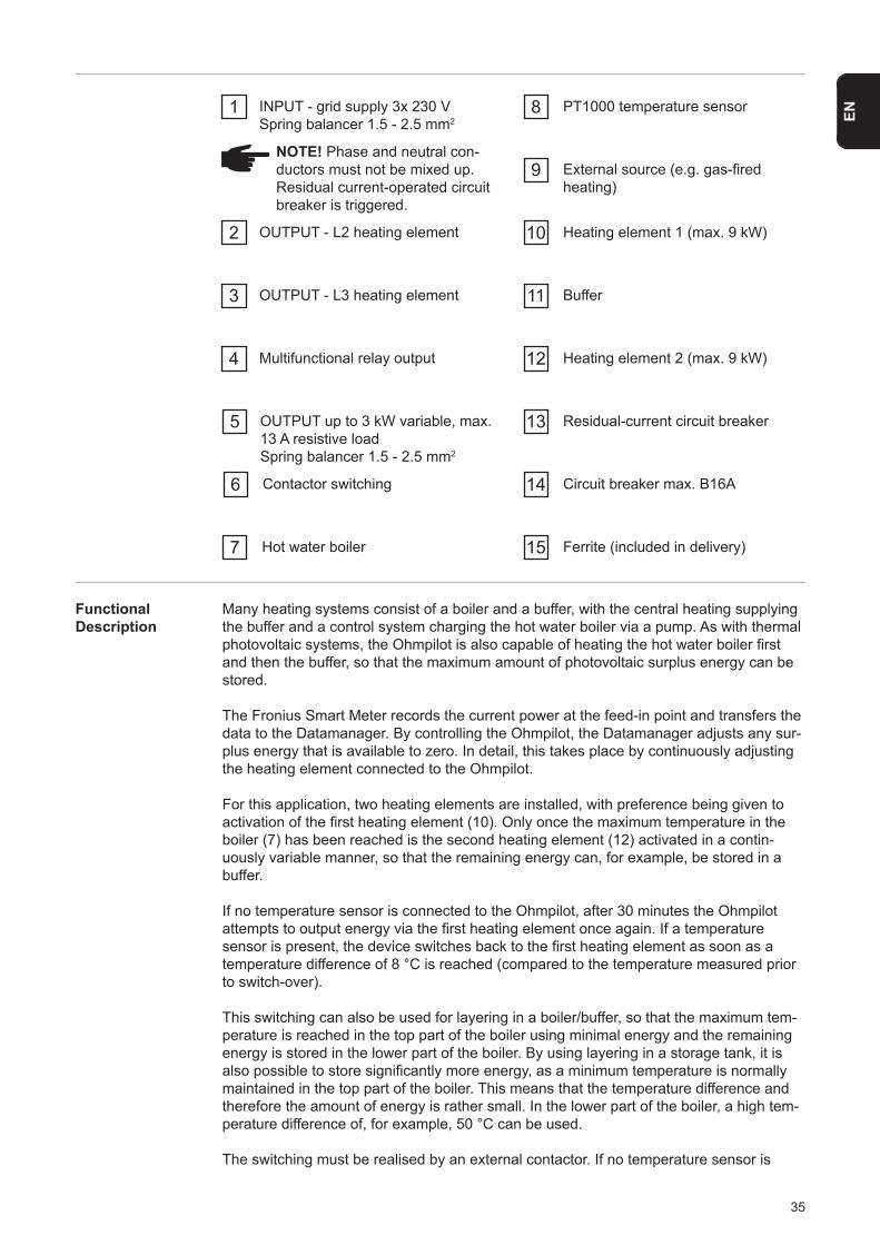
EN1 INPUT - grid supply 3x 230 VSpring balancer 1.5 - 2.5 mm2
NOTE! Phase and neutral con-ductors must not be mixed up. Residual current-operated circuit breaker is triggered.
2 OUTPUT - L2 heating element
3
4
5
OUTPUT - L3 heating element
Multifunctional relay output
OUTPUT up to 3 kW variable, max. 13 A resistive loadSpring balancer 1.5 - 2.5 mm2
7
6
Hot water boiler
Contactor switching
8 PT1000 temperature sensor
9
10
External source (e.g. gas-fired heating)
Heating element 1 (max. 9 kW)
11
13
12
14
Buffer
Residual-current circuit breaker
Heating element 2 (max. 9 kW)
Circuit breaker max. B16A
15 Ferrite (included in delivery)
Functional Description
Many heating systems consist of a boiler and a buffer, with the central heating supplying the buffer and a control system charging the hot water boiler via a pump. As with thermal photovoltaic systems, the Ohmpilot is also capable of heating the hot water boiler first and then the buffer, so that the maximum amount of photovoltaic surplus energy can be stored.
The Fronius Smart Meter records the current power at the feed-in point and transfers the data to the Datamanager. By controlling the Ohmpilot, the Datamanager adjusts any sur-plus energy that is available to zero. In detail, this takes place by continuously adjusting the heating element connected to the Ohmpilot.
For this application, two heating elements are installed, with preference being given to activation of the first heating element (10). Only once the maximum temperature in the boiler (7) has been reached is the second heating element (12) activated in a contin-uously variable manner, so that the remaining energy can, for example, be stored in a buffer.
If no temperature sensor is connected to the Ohmpilot, after 30 minutes the Ohmpilot attempts to output energy via the first heating element once again. If a temperature sensor is present, the device switches back to the first heating element as soon as a temperature difference of 8 °C is reached (compared to the temperature measured prior to switch-over).
This switching can also be used for layering in a boiler/buffer, so that the maximum tem-perature is reached in the top part of the boiler using minimal energy and the remaining energy is stored in the lower part of the boiler. By using layering in a storage tank, it is also possible to store significantly more energy, as a minimum temperature is normally maintained in the top part of the boiler. This means that the temperature difference and therefore the amount of energy is rather small. In the lower part of the boiler, a high tem-perature difference of, for example, 50 °C can be used.
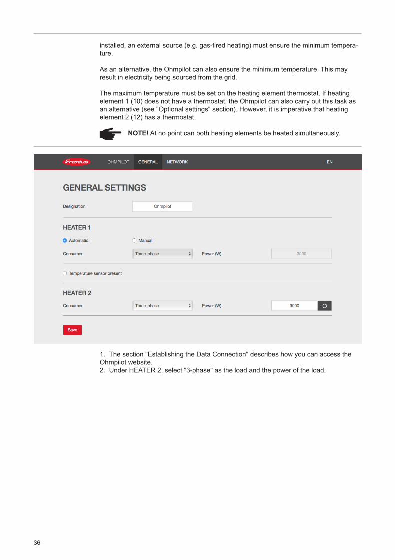
The switching must be realised by an external contactor. If no temperature sensor is
36
installed, an external source (e.g. gas-fired heating) must ensure the minimum tempera-ture.
As an alternative, the Ohmpilot can also ensure the minimum temperature. This may result in electricity being sourced from the grid.
The maximum temperature must be set on the heating element thermostat. If heating element 1 (10) does not have a thermostat, the Ohmpilot can also carry out this task as an alternative (see "Optional settings" section). However, it is imperative that heating element 2 (12) has a thermostat.
NOTE! At no point can both heating elements be heated simultaneously.
1. The section "Establishing the Data Connection" describes how you can access the Ohmpilot website.2. Under HEATER 2, select "3-phase" as the load and the power of the load.
37
EN
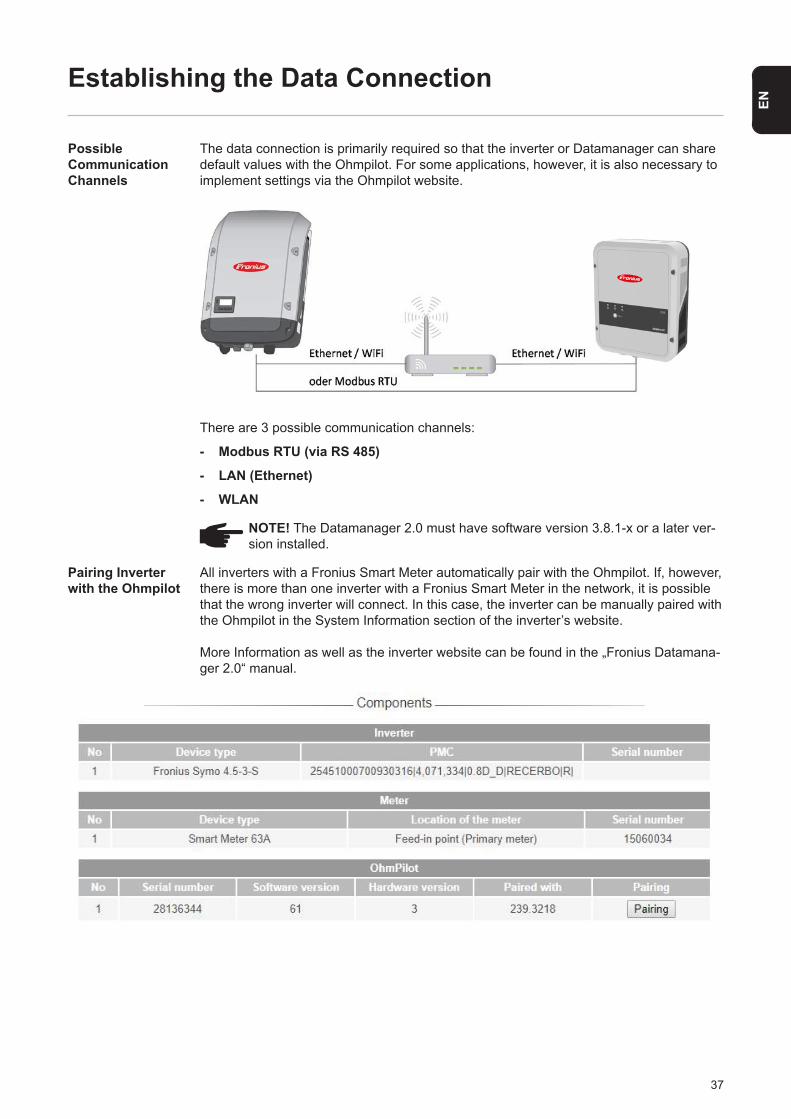
The data connection is primarily required so that the inverter or Datamanager can share default values with the Ohmpilot. For some applications, however, it is also necessary to implement settings via the Ohmpilot website.
There are 3 possible communication channels:
- Modbus RTU (via RS 485)
- LAN (Ethernet)
- WLAN
Establishing the Data Connection
Possible Communication Channels
NOTE! The Datamanager 2.0 must have software version 3.8.1-x or a later ver-sion installed.
All inverters with a Fronius Smart Meter automatically pair with the Ohmpilot. If, however, there is more than one inverter with a Fronius Smart Meter in the network, it is possible that the wrong inverter will connect. In this case, the inverter can be manually paired with the Ohmpilot in the System Information section of the inverter’s website.
More Information as well as the inverter website can be found in the „Fronius Datamana-ger 2.0“ manual.
Pairing Inverter with the Ohmpilot

38
Establishing a Connection viaModbus RTU
1. Connect the bus cabling (B) to the Ohmpilot. (The bus cabling is carried out in parallel via the TX+, TX- and GND cables with the Fronius Smart Meter and the Fronius inverter or Datamanager 2.0).
2. Terminate the RS485 bus with a resistance at the first and last device. The resistance can be activated on the Ohmpilot using DIP switch number 5. See (A).
3. The Modbus address can be set using numbers 1-3. Default address: 40 (For future applications, the Modbus address can be changed using the DIP switches on the Ohmpilot.)
(A) DIP switchesDIP 1-3 = Modbus address BCDDIP 4 = ReserveDIP 5 = Terminating resistance (120 Ohm)
Fronius Smart Meter OUTPUT Fronius RS 485
Fronius Datamanager
2.0INPUT DT/PE Ohmpilot
+ 120Ω1 3
Rx / T-x GND
4 6 7 9 111 2 3 4 5DA B C - D+ D- D+ D- -
120Ω
OFF
(A)
(B)
WARNING! Use a data cable that is clearly distinguishable from the mains cable, so that there is no confusion and injury and damage to property are avoided.
IMPORTANT! In the case of incorrect cabling, this will be displayed by the red LED flashing 1x.
39
EN
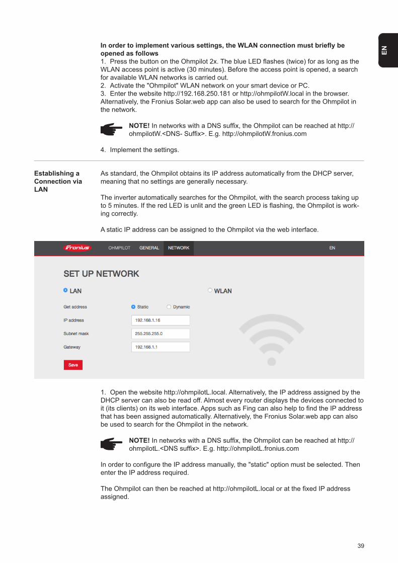
Establishing a Connection via LAN
As standard, the Ohmpilot obtains its IP address automatically from the DHCP server, meaning that no settings are generally necessary.
The inverter automatically searches for the Ohmpilot, with the search process taking up to 5 minutes. If the red LED is unlit and the green LED is flashing, the Ohmpilot is work-ing correctly.
A static IP address can be assigned to the Ohmpilot via the web interface.
1. Open the website http://ohmpilotL.local. Alternatively, the IP address assigned by the DHCP server can also be read off. Almost every router displays the devices connected to it (its clients) on its web interface. Apps such as Fing can also help to find the IP address that has been assigned automatically. Alternatively, the Fronius Solar.web app can also be used to search for the Ohmpilot in the network.
NOTE! In networks with a DNS suffix, the Ohmpilot can be reached at http:// ohmpilotL.<DNS suffix>. E.g. http://ohmpilotL.fronius.com
In order to configure the IP address manually, the "static" option must be selected. Then enter the IP address required.
The Ohmpilot can then be reached at http://ohmpilotL.local or at the fixed IP address assigned.
In order to implement various settings, the WLAN connection must briefly be opened as follows1. Press the button on the Ohmpilot 2x. The blue LED flashes (twice) for as long as the WLAN access point is active (30 minutes). Before the access point is opened, a search for available WLAN networks is carried out.2. Activate the "Ohmpilot" WLAN network on your smart device or PC.3. Enter the website http://192.168.250.181 or http://ohmpilotW.local in the browser. Alternatively, the Fronius Solar.web app can also be used to search for the Ohmpilot in the network.
NOTE! In networks with a DNS suffix, the Ohmpilot can be reached at http:// ohmpilotW.<DNS- Suffix>. E.g. http://ohmpilotW.fronius.com
4. Implement the settings.
40
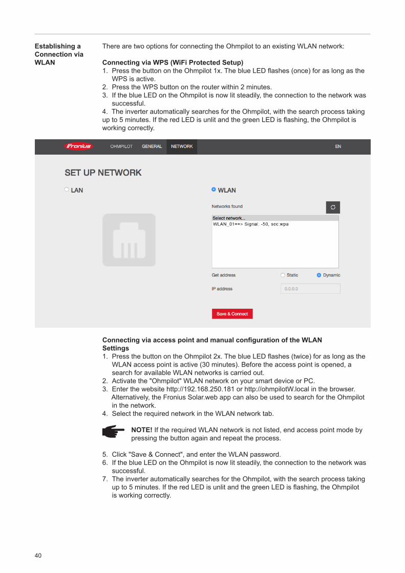
Establishing a Connection via WLAN
There are two options for connecting the Ohmpilot to an existing WLAN network:
Connecting via WPS (WiFi Protected Setup)1. Press the button on the Ohmpilot 1x. The blue LED flashes (once) for as long as the
WPS is active.2. Press the WPS button on the router within 2 minutes.3. If the blue LED on the Ohmpilot is now lit steadily, the connection to the network was
successful.4. The inverter automatically searches for the Ohmpilot, with the search process taking up to 5 minutes. If the red LED is unlit and the green LED is flashing, the Ohmpilot is working correctly.
Connecting via access point and manual configuration of the WLANSettings1. Press the button on the Ohmpilot 2x. The blue LED flashes (twice) for as long as the WLAN access point is active (30 minutes). Before the access point is opened, a search for available WLAN networks is carried out.2. Activate the "Ohmpilot" WLAN network on your smart device or PC.3. Enter the website http://192.168.250.181 or http://ohmpilotW.local in the browser. Alternatively, the Fronius Solar.web app can also be used to search for the Ohmpilot in the network.4. Select the required network in the WLAN network tab.
NOTE! If the required WLAN network is not listed, end access point mode by pressing the button again and repeat the process.
5. Click "Save & Connect", and enter the WLAN password.6. If the blue LED on the Ohmpilot is now lit steadily, the connection to the network was successful.7. The inverter automatically searches for the Ohmpilot, with the search process taking up to 5 minutes. If the red LED is unlit and the green LED is flashing, the Ohmpilot is working correctly.

41
EN
IMPORTANT! When the access point is opened, it is not possible to scan the WLAN networks.
A static IP address can be assigned to the Ohmpilot via the web interface.
The Ohmpilot can then be reached at http://ohmpilotW.local or at the fixed IP address assigned. Alternatively, the Fronius Solar.web app can also be used to search for the Ohmpilot in the network.
NOTE! Only one device can connect to the Ohmpilot.
NOTE! In networks with a DNS suffix, the Ohmpilot can be reached at http:// ohmpilotW.<DNS- Suffix>. E.g. http://ohmpilotW.fronius.com
42
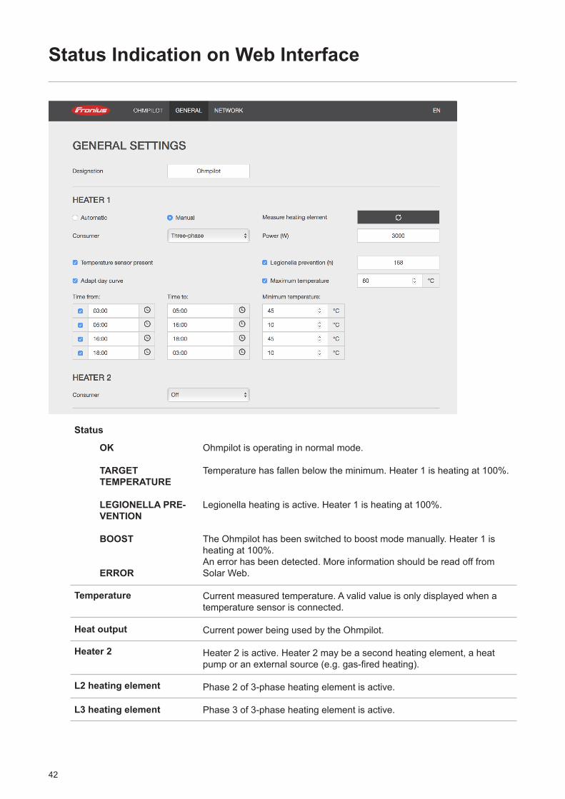
OK
TARGET TEMPERATURE
LEGIONELLA PRE-VENTION
BOOST
ERROR
Ohmpilot is operating in normal mode.
Temperature has fallen below the minimum. Heater 1 is heating at 100%.
Legionella heating is active. Heater 1 is heating at 100%.
The Ohmpilot has been switched to boost mode manually. Heater 1 is heating at 100%.An error has been detected. More information should be read off from Solar Web.
Current measured temperature. A valid value is only displayed when a temperature sensor is connected.
Current power being used by the Ohmpilot.
Heater 2 is active. Heater 2 may be a second heating element, a heat pump or an external source (e.g. gas-fired heating).
Phase 2 of 3-phase heating element is active.
Phase 3 of 3-phase heating element is active.
Status Indication on Web Interface
Status
Temperature
Heat output
Heater 2
L2 heating element
L3 heating element
43
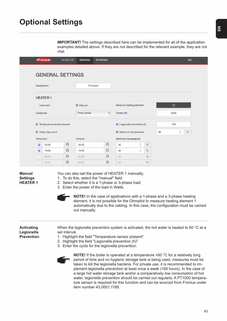
EN
When the legionella prevention system is activated, the hot water is heated to 60 °C at a set interval.1. Highlight the field "Temperature sensor present"2. Highlight the field "Legionella prevention (h)"3. Enter the cycle for the legionella prevention.
NOTE! If the boiler is operated at a temperature <60 °C for a relatively long period of time and no hygienic storage tank is being used, measures must be taken to kill the legionella bacteria. For private use, it is recommended to im-plement legionella prevention at least once a week (168 hours). In the case of a large hot water storage tank and/or a comparatively low consumption of hot water, legionella prevention should be carried out regularly. A PT1000 tempera-ture sensor is required for this function and can be sourced from Fronius under item number 43,0001,1188.
Optional Settings
IMPORTANT! The settings described here can be implemented for all of the application examples detailed above. If they are not described for the relevant example, they are not vital.
You can also set the power of HEATER 1 manually. 1. To do this, select the "manual" field.2. Select whether it is a 1-phase or 3-phase load.3. Enter the power of the load in Watts.
NOTE! In the case of applications with a 1-phase and a 3-phase heating element, it is not possible for the Ohmpilot to measure heating element 1 automatically due to the cabling. In this case, the configuration must be carried out manually.
Manual SettingsHEATER 1
Activating LegionellaPrevention
44
This function ensures that a required temperature is not undercut. If there is not sufficient surplus power available, the external source will be started up, if activated, or otherwise electricity will be drawn from the grid in order to ensure a minimum temperature.
Up to four time periods can be defined so that, for example, higher hot water temper-atures are only certain to be available at night, but more potential is possible for the surplus during the day due to the fact that a lower target temperature is selected.
1. Highlight the field "Temperature sensor present"2. Highlight the field "Adapt day curve"3. Under "Time from", enter the time from which the Ohmpilot should start to heat to the new target temperature. 4. Under “Time until”, enter the time to which the Ohmpilot should heat to the target tem-perature.5. Under “Target temperature”, enter the required final temperature.
NOTE! If time ranges overlap, the higher temperature is used so that e.g. a base temperature of 40°C can be set for the whole day and increased to 50°C at specific times.
NOTE! If time ranges are not defined, heating will only occur with excess PV energy and not via the network or an external source.
NOTE! If heater 1 is the primary heat source, the day curve must in all cases be adapted to ensure the required minimum temperature. A PT1000 temperature sensor is required for this function and can be sourced from Fronius under item
number 43,0001,1188. The position of the temperature sensor in the boiler should be chosen so that sufficient hot water is available. However, it must in all cases be installed above the heating element/external source.
Adapting the Day Curve
Temperature Limitation
If heater 1 does not have a configurable thermostat, this function can be used to limit the temperature.
1. Highlight the field "Temperature sensor present"2. Highlight the field "Temperature limitation"3. Enter the maximum temperature (e.g. 60 °C).
NOTE! This function is only possible for heater 1. If a second heating element is in use as heater 2, this must have a thermostat. A PT1000 temperature sensor is required for this function and can be sourced from Fronius under item number
43,0001,1188. The temperature sensor should be installed just above the heating element, so that the cold water flowing in is immediately heated up again and the maximum storage amount is therefore used.
WARNING! No guaranteed legionella prevention.
Example:03:00 - 05:00 45 ° C => At 6:00 am hot water is available for showers. After showers, hot water is only produced with surplus energy.16:00 - 18:00 45 ° C => If there was not sufficient excess energy, the hot water is heated to the target temperature. After showers, water should no longer be heated to keep heat losses low.
45
EN
Error List:
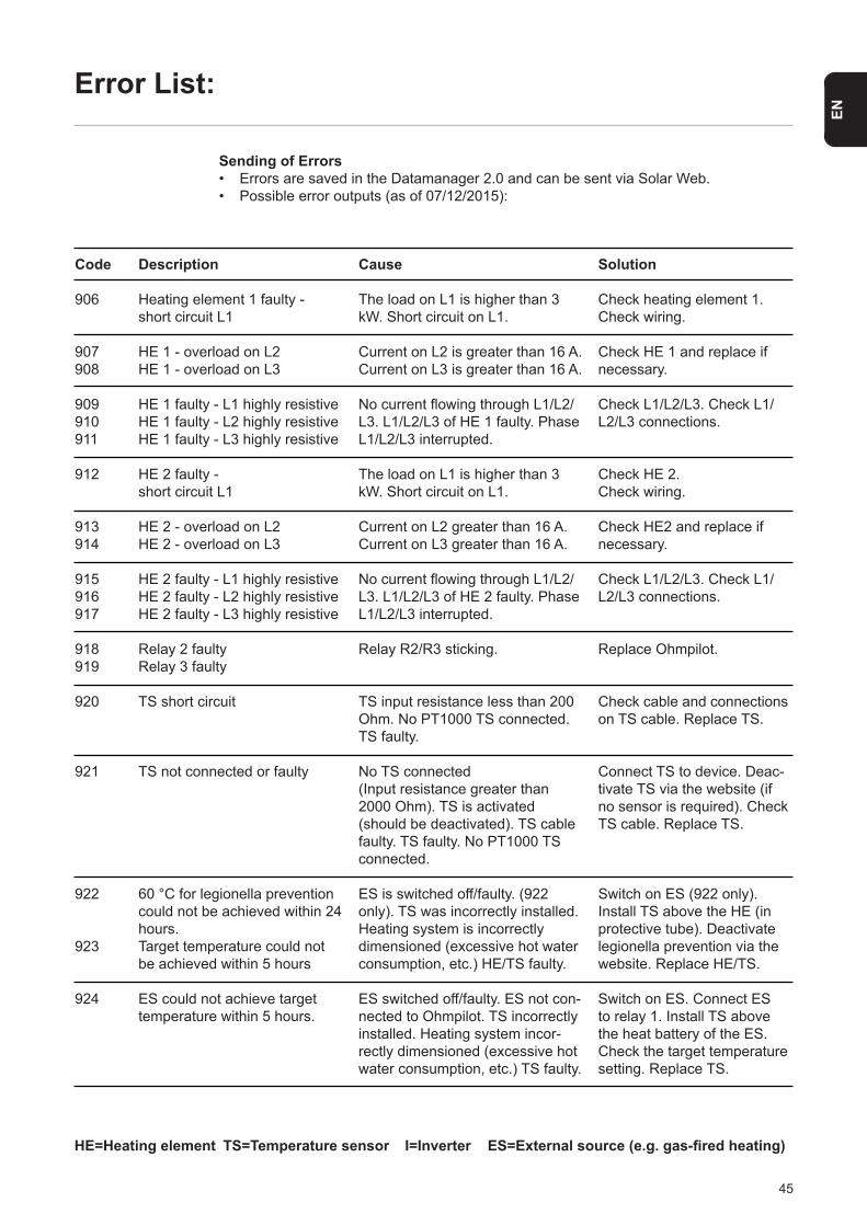
Sending of Errors• Errors are saved in the Datamanager 2.0 and can be sent via Solar Web. • Possible error outputs (as of 07/12/2015):
Code
906
907908
909910911
912
913914
915916917
918919
920
921
922
923
924
Description
Heating element 1 faulty - short circuit L1
HE 1 - overload on L2HE 1 - overload on L3
HE 1 faulty - L1 highly resistive HE 1 faulty - L2 highly resistive HE 1 faulty - L3 highly resistive
HE 2 faulty - short circuit L1
HE 2 - overload on L2HE 2 - overload on L3
HE 2 faulty - L1 highly resistive HE 2 faulty - L2 highly resistive HE 2 faulty - L3 highly resistive
Relay 2 faultyRelay 3 faulty
TS short circuit
TS not connected or faulty
60 °C for legionella prevention could not be achieved within 24 hours.Target temperature could not be achieved within 5 hours
ES could not achieve target temperature within 5 hours.
Cause
The load on L1 is higher than 3 kW. Short circuit on L1.
Current on L2 is greater than 16 A. Current on L3 is greater than 16 A.
No current flowing through L1/L2/L3. L1/L2/L3 of HE 1 faulty. Phase L1/L2/L3 interrupted.
The load on L1 is higher than 3 kW. Short circuit on L1.
Current on L2 greater than 16 A. Current on L3 greater than 16 A.
No current flowing through L1/L2/L3. L1/L2/L3 of HE 2 faulty. Phase L1/L2/L3 interrupted.
Relay R2/R3 sticking.
TS input resistance less than 200 Ohm. No PT1000 TS connected. TS faulty.
No TS connected (Input resistance greater than 2000 Ohm). TS is activated(should be deactivated). TS cable faulty. TS faulty. No PT1000 TS connected.
ES is switched off/faulty. (922 only). TS was incorrectly installed. Heating system is incorrectly dimensioned (excessive hot water consumption, etc.) HE/TS faulty.
ES switched off/faulty. ES not con-nected to Ohmpilot. TS incorrectly installed. Heating system incor-rectly dimensioned (excessive hot water consumption, etc.) TS faulty.
Solution
Check heating element 1.Check wiring.
Check HE 1 and replace if necessary.
Check L1/L2/L3. Check L1/L2/L3 connections.
Check HE 2. Check wiring.
Check HE2 and replace if necessary.
Check L1/L2/L3. Check L1/L2/L3 connections.
Replace Ohmpilot.
Check cable and connections on TS cable. Replace TS.
Connect TS to device. Deac-tivate TS via the website (if no sensor is required). Check TS cable. Replace TS.
Switch on ES (922 only). Install TS above the HE (in protective tube). Deactivate legionella prevention via the website. Replace HE/TS.
Switch on ES. Connect ES to relay 1. Install TS above the heat battery of the ES. Check the target temperature setting. Replace TS.
HE=Heating element TS=Temperature sensor I=Inverter ES=External source (e.g. gas-fired heating)
46
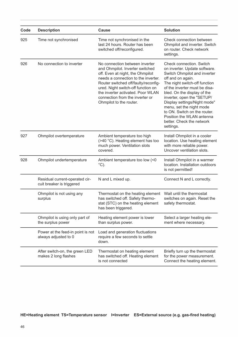
Code
925
926
927
928
Description
Time not synchronised
No connection to inverter
Ohmpilot overtemperature
Ohmpilot undertemperature
Residual current-operated cir-cuit breaker is triggered
Ohmpilot is not using any surplus
Ohmpilot is using only part of the surplus power
Power at the feed-in point is not always adjusted to 0
After switch-on, the green LED makes 2 long flashes
Cause
Time not synchronised in the last 24 hours. Router has been switched off/reconfigured.
No connection between inverter and Ohmpilot. Inverter switched off. Even at night, the Ohmpilot needs a connection to the inverter. Router switched off/faulty/reconfig-ured. Night switch-off function on the inverter activated. Poor WLAN connection from the inverter or Ohmpilot to the router.
Ambient temperature too high (>40 °C). Heating element has too much power. Ventilation slots covered.
Ambient temperature too low (<0 °C).
N and L mixed up.
Thermostat on the heating element has switched off. Safety thermo-stat (STC) on the heating element has been triggered.
Heating element power is lower than surplus power.
Load and generation fluctuations require a few seconds to settle down.
Thermostat on heating element has switched off. Heating element is not connected
Solution
Check connection between Ohmpilot and inverter. Switch on router. Check network settings.
Check connection. Switch on inverter. Update software. Switch Ohmpilot and inverter off and on again. The night switch-off function of the inverter must be disa-bled. On the display of the inverter, open the "SETUP/Display settings/Night mode" menu, set the night mode to ON. Switch on the router. Position the WLAN antenna better. Check the network settings.
Install Ohmpilot in a cooler location. Use heating element with more reliable power. Uncover ventilation slots.
Install Ohmpilot in a warmer location. Installation outdoors is not permitted!
Connect N and L correctly.
Wait until the thermostat switches on again. Reset the safety thermostat.
Select a larger heating ele-ment where necessary.
Briefly turn up the thermostat for the power measurement. Connect the heating element.
HE=Heating element TS=Temperature sensor I=Inverter ES=External source (e.g. gas-fired heating)

47
EN
Detailed, country-specific warranty terms are available on the internet: www.fronius.com/solar/warranty
If you decide in the future to replace your Ohmpilot, Fronius will take back the old device and arrange for it to be recycled in an appropriate manner.
CE mark The devices comply with all the requisite and relevant standards and guidelines that form part of the relevant EU Directive, and are therefore permitted to display the CE mark.
Warranty Terms and Conditions, and Disposal
Fronius Manufac-turer's Warranty
Disposal
Applicable Standards and Guidelines

48
FrequencyNominal voltageMax. input current
Modbus RTULANWLANTemperature sensor
Analogue out 1-phase/3-phaseAnalogue nominal voltage per phaseAnalogue out short circuit currentRelay out max. currentMultifunctional relay outEfficiency during rated operationConsumption during standby
Dimensions (height x width x depth)WeightDegree of protectionMountingAmbient temperature rangePermitted humidityCoolingStorage temperatureEMC device classOvervoltage category Pollution level
50 Hz230 V / 400 V
1 X 16 A / 3 x 16 A
RS 485, max. 1000 m, screened and twistedEthernet at least CAT5, screened
IEEE 802.11 b/g/nPT1000 (max. 30 m)
Continuously variable 0 - 3 / 0 - 9 kW13 A
16 A (max. 5 seconds)L2 / L3 16 A (max. 5 seconds)
min. 15 V / 2 mA; max. 16 A (max. 5 seconds)at least 98%
typically 1.8 W
340 mm x 270 mm x 123 mm3.9 kg
IP54Wall
0 to 40 °C0%-99% (non-condensing)
Convection-40 to 70 °C
B33
Technical Data
Input Data
Interfaces
Output Data
General Data
49
EN
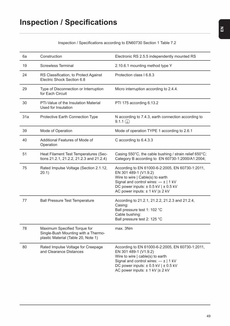
Electronic RS 2.5.5 independently mounted RS
2.10.6.1 mounting method type Y
Protection class I 6.8.3
Micro interruption according to 2.4.4.
PTI 175 according 6.13.2
N according to 7.4.3, earth connection according to 9.1.1
Mode of operation TYPE 1 according to 2.6.1
C according to 6.4.3.3
Casing 550°C, the cable bushing / strain relief 650°C; Category B according to EN 60730-1:2000/A1:2004;
According to EN 61000-6-2:2005, EN 60730-1:2011, EN 301 489-1 (V1.9.2)Wire to wire | Cable(s) to earthSignal and control wires: --- ± | 1 kVDC power inputs: ± 0.5 kV | ± 0.5 kVAC power inputs: ± 1 kV |± 2 kV
According to 21.2.1, 21.2.2, 21.2.3 and 21.2.4,Casing: Ball pressure test 1: 102 °CCable bushing:Ball pressure test 2: 125 °C
max. 3Nm
According to EN 61000-6-2:2005, EN 60730-1:2011,EN 301 489-1 (V1.9.2)Wire to wire | cable(s) to earthSignal and control wires: --- ± | 1 kVDC power inputs: ± 0.5 kV | ± 0.5 kVAC power inputs: ± 1 kV |± 2 kV
Inspection / Specifications
Inspection / Specifications according to EN60730 Section 1 Table 7.2
6a
19
24
29
30
31a
39
40
51
75
77
78
80
Construction
Screwless Terminal
RS Classification, to Protect Against Electric Shock Section 6.8
Type of Disconnection or Interruption for Each Circuit
PTI-Value of the Insulation Material Used for Insulation
Protective Earth Connection Type
Mode of Operation
Additional Features of Mode ofOperation
Heat Filament Test Temperatures (Sec-tions 21.2.1, 21.2.2, 21.2.3 and 21.2.4)
Rated Impulse Voltage (Section 2.1.12, 20.1)
Ball Pressure Test Temperature
Maximum Specified Torque for Single-Bush Mounting with a Thermo-plastic Material (Table 20, Note 1)
Rated Impulse Voltage for Creepage and Clearance Distances

50

51
EN

52
Fronius Worldwide - www.fronius.com/addresses
Fronius International GmbH 4600 Wels, Froniusplatz 1, Austria E-mail: [email protected] http://www.fronius.com
The addresses of all our sales branches and partner companies can be found at http://www.fronius.com/addresses.
Fronius USA LLC Solar Electronics Division 6797 Fronius Drive, Portage, IN 46368E-mail: [email protected] http://www.fronius-usa.com
Related Documents


