IEC 61850 — TECHNICAL GUIDE ANSI medium voltage metal-clad digital switchgear Commissioning and testing guide

Welcome message from author
This document is posted to help you gain knowledge. Please leave a comment to let me know what you think about it! Share it to your friends and learn new things together.
Transcript
IEC 61850
—TECHNIC AL GUIDE
ANSI medium voltage metal-claddigital switchgearCommissioning and testing guide

— Table of contents
04 Warranty and general information
05 Introduction
06 ANSI medium voltage metal-clad digital switchgear
07– 08 Ethernet network verification
09– 14 Managed Ethernet switches
15 – 17 Interconnections
18 – 24 Primary testing-current sensors
25 – 28 Primary testing-voltage sensors
29 – 33 Apparatus control testing
34 Secondary testing of protection relays
35– 41 FT-14D Flexitest switch
42– 45 Recommended troubleshooting tools
46 Glossary
4 ANSI MEDIUM VOLTAGE METAL-CLAD DIGITAL SWITCHGEAR
—Warranty and general information
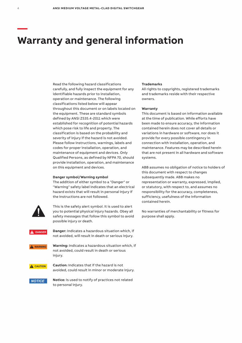
Read the following hazard classifications carefully, and fully inspect the equipment for any identifiable hazards prior to installation, operation or maintenance. The following classifications listed below will appear throughout this document or on labels located on the equipment. These are standard symbols defined by ANSI Z535.4-2011 which were established for recognition of potential hazards which pose risk to life and property. The classification is based on the probability and severity of injury if the hazard is not avoided. Please follow instructions, warnings, labels and codes for proper installation, operation, and maintenance of equipment and devices. Only Qualified Persons, as defined by NFPA 70, should provide installation, operation, and maintenance on this equipment and devices.
Danger symbol/Warning symbolThe addition of either symbol to a "Danger" or "Warning" safety label indicates that an electrical hazard exists that will result in personal injury if the instructions are not followed.
This is the safety alert symbol. It is used to alert you to potential physical injury hazards. Obey all safety messages that follow this symbol to avoid possible injury or death.
Danger: Indicates a hazardous situation which, if not avoided, will result in death or serious injury.
Warning: Indicates a hazardous situation which, if not avoided, could result in death or serious injury.
Caution: Indicates that if the hazard is not avoided, could result in minor or moderate injury.
Notice: Is used to notify of practices not related to personal injury.
TrademarksAll rights to copyrights, registered trademarks and trademarks reside with their respective owners.
WarrantyThis document is based on information available at the time of publication. While efforts have been made to ensure accuracy, the information contained herein does not cover all details or variations in hardware or software, nor does it provide for every possible contingency in connection with installation, operation, and maintenance. Features may be described herein that are not present in all hardware and software systems.
ABB assumes no obligation of notice to holders of this document with respect to changes subsequently made. ABB makes no representation or warranty, expressed, implied, or statutory, with respect to, and assumes no responsibility for the accuracy, completeness, sufficiency, usefulness of the information contained herein.
No warranties of merchantability or fitness for purpose shall apply.
WARNING
NOTICE
CAUTION
DANGER
WARNING
CAUTION
NOTICE
SAFETYINSTRUCTIONS
DANGER
WARNING
CAUTION
NOTICE
SAFETYINSTRUCTIONS
CO M M ISSI O N I N G A N D TE S TI N G G U I D E 5
—Introduction
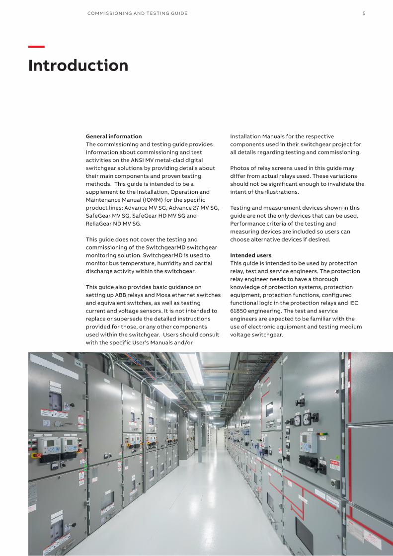
General informationThe commissioning and testing guide provides information about commissioning and test activities on the ANSI MV metal-clad digital switchgear solutions by providing details about their main components and proven testing methods. This guide is intended to be a supplement to the Installation, Operation and Maintenance Manual (IOMM) for the specific product lines: Advance MV SG, Advance 27 MV SG, SafeGear MV SG, SafeGear HD MV SG and ReliaGear ND MV SG.
This guide does not cover the testing and commissioning of the SwitchgearMD switchgear monitoring solution. SwitchgearMD is used to monitor bus temperature, humidity and partial discharge activity within the switchgear.
This guide also provides basic guidance on setting up ABB relays and Moxa ethernet switches and equivalent switches, as well as testing current and voltage sensors. It is not intended to replace or supersede the detailed instructions provided for those, or any other components used within the switchgear. Users should consult with the specific User’s Manuals and/or
Installation Manuals for the respective components used in their switchgear project for all details regarding testing and commissioning.
Photos of relay screens used in this guide may differ from actual relays used. These variations should not be significant enough to invalidate the intent of the illustrations.
Testing and measurement devices shown in this guide are not the only devices that can be used. Performance criteria of the testing and measuring devices are included so users can choose alternative devices if desired.
Intended usersThis guide is intended to be used by protection relay, test and service engineers. The protection relay engineer needs to have a thorough knowledge of protection systems, protection equipment, protection functions, configured functional logic in the protection relays and IEC 61850 engineering. The test and service engineers are expected to be familiar with the use of electronic equipment and testing medium voltage switchgear.
6 ANSI MEDIUM VOLTAGE METAL-CLAD DIGITAL SWITCHGEAR
—ANSI medium voltage metal-clad digital switchgear
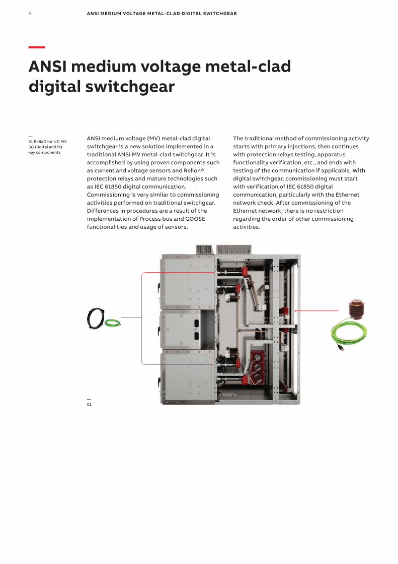
ANSI medium voltage (MV) metal-clad digital switchgear is a new solution implemented in a traditional ANSI MV metal-clad switchgear. It is accomplished by using proven components such as current and voltage sensors and Relion® protection relays and mature technologies such as IEC 61850 digital communication.Commissioning is very similar to commissioning activities performed on traditional switchgear. Differences in procedures are a result of the implementation of Process bus and GOOSE functionalities and usage of sensors.
The traditional method of commissioning activity starts with primary injections, then continues with protection relays testing, apparatus functionality verification, etc., and ends with testing of the communication if applicable. With digital switchgear, commissioning must start with verification of IEC 61850 digital communication, particularly with the Ethernet network check. After commissioning of the Ethernet network, there is no restriction regarding the order of other commissioning activities.
—01 ReliaGear ND MV SG Digital and its key components
—01
CO M M ISSI O N I N G A N D TE S TI N G G U I D E 7
—Ethernet network verification
The Ethernet network interconnects protection relays in a substation. As the GOOSE and Process bus are used, having a functional network is essential for most of the tests. The network may or may not be set up and tested in the factory, depending upon purchase contract agreements. Therefore, after switchgear is assembled onsite, it may be necessary to set up the network and then verify its functionality. Before starting any testing of the communication, properly set the Ethernet settings in the protection relays, set the Ethernet switches and, only then, interconnect the Ethernet network according to the project documentation. It is assumed that the protection and control circuits are powered from either the power supply identified in the project schematic diagrams, or an alternate power supply if the switchgear is not energized.
Protection relaysBefore starting any secondary testing of the protection relay functions, verify if the IP addresses, the network topology and time synchronization settings are in accordance with the project documentation.
• IP address setting: Check communication board setting according to documentation (for example, the Network Overview diagram).
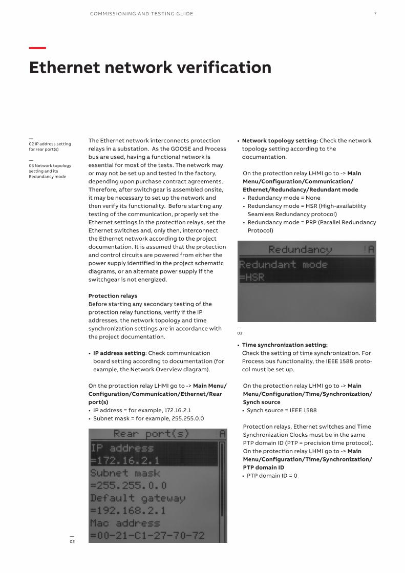
On the protection relay LHMI go to -> Main Menu/Configuration/Communication/Ethernet/Rear port(s)• IP address = for example, 172.16.2.1• Subnet mask = for example, 255.255.0.0
• Network topology setting: Check the network topology setting according to the documentation.
—02 IP address setting for rear port(s)
—03 Network topology setting and its Redundancy mode
—02
—03
On the protection relay LHMI go to -> Main Menu/Configuration/Communication/Ethernet/Redundancy/Redundant mode• Redundancy mode = None• Redundancy mode = HSR (High-availability
Seamless Redundancy protocol)• Redundancy mode = PRP (Parallel Redundancy
Protocol)
• Time synchronization setting: Check the setting of time synchronization. For Process bus functionality, the IEEE 1588 proto-col must be set up.
On the protection relay LHMI go to -> Main Menu/Configuration/Time/Synchronization/Synch source• Synch source = IEEE 1588 Protection relays, Ethernet switches and Time Synchronization Clocks must be in the same PTP domain ID (PTP = precision time protocol).On the protection relay LHMI go to -> Main Menu/Configuration/Time/Synchronization/ PTP domain ID• PTP domain ID = 0
8 ANSI MEDIUM VOLTAGE METAL-CLAD DIGITAL SWITCHGEAR
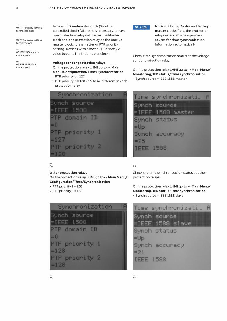
Voltage sender protection relaysOn the protection relay LHMI go to -> Main Menu/Configuration/Time/Synchronisation• PTP priority 1 = 127• PTP priority 2 = 128-255 to be different in each
protection relay
Check time synchronization status at the voltage sender protection relay.
On the protection relay LHMI go to -> Main Menu/Monitoring/IED status/Time synchronization• Synch source = IEEE 1588 master
In case of Grandmaster clock (Satellite controlled clock) failure, it is necessary to have one protection relay defined as the Master clock and one protection relay as the Backup master clock. It is a matter of PTP priority setting. Devices with a lower PTP priority 2 value become the first master clock.
Check the time synchronization status at other protection relays.
On the protection relay LHMI go to -> Main Menu/Monitoring/IED status/Time synchronization• Synch source = IEEE 1588 slave
Notice: If both, Master and Backup master clocks fails, the protection relays establish a new primary source for time synchronization information automatically.
—04
—05
—06
—07
—04 PTP priority setting for Master clock
—05 PTP priority setting for Slave clock
—06 IEEE 1588 master clock status
—07 IEEE 1588 slave clock status
Other protection relaysOn the protection relay LHMI go to -> Main Menu/Configuration/Time/Synchronization• PTP priority 1 = 128• PTP priority 2 = 128
NOTICE
CO M M ISSI O N I N G A N D TE S TI N G G U I D E 9
—08 MX Config – location of globe icon
—09 Broadcast Search Filters
—Managed Ethernet switches
To create a reliable Ethernet network for IEC 61850 communication, a managed Ethernet switch (e.g., from Moxa) is recommended to be used. The most important settings of Moxa EDS family Ethernet switches to be observed are highlighted in this section.
This section provides the basic information on how to make the initial setup of a typical Moxa switch. User must refer to the correct User’s Manual and/or Instruction Manual for the Moxa switch for details of how to completely setup and/or program the Moxa ethernet switches. The instructions within the Moxa User’s Manual and/or Installation Manuals take precedence over all instructions within this guide.
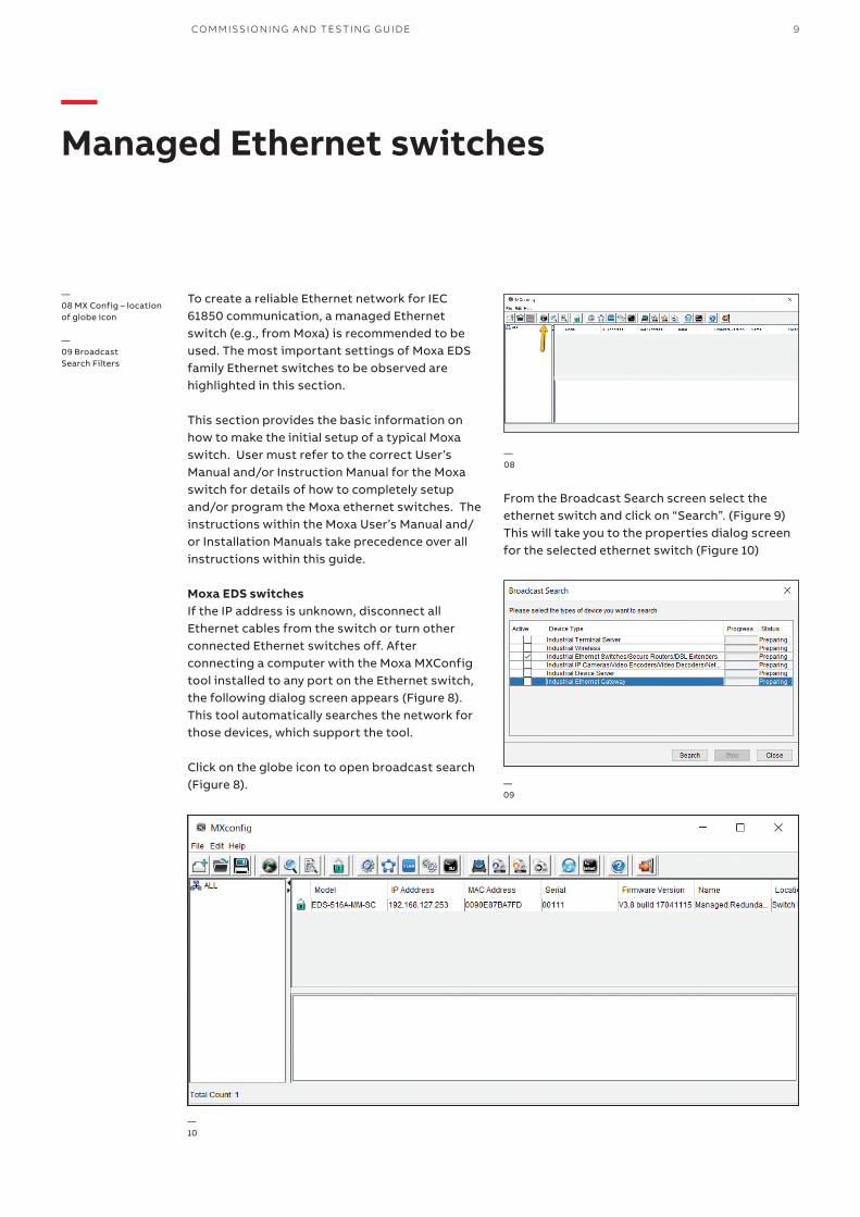
Moxa EDS switchesIf the IP address is unknown, disconnect all Ethernet cables from the switch or turn other connected Ethernet switches off. After connecting a computer with the Moxa MXConfig tool installed to any port on the Ethernet switch, the following dialog screen appears (Figure 8). This tool automatically searches the network for those devices, which support the tool.
Click on the globe icon to open broadcast search (Figure 8).
—08
—09
From the Broadcast Search screen select the ethernet switch and click on “Search”. (Figure 9) This will take you to the properties dialog screen for the selected ethernet switch (Figure 10)
—10
10 ANSI MEDIUM VOLTAGE METAL-CLAD DIGITAL SWITCHGEAR
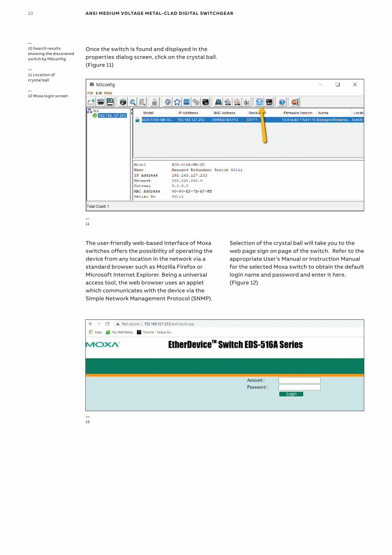
Selection of the crystal ball will take you to the web page sign on page of the switch. Refer to the appropriate User’s Manual or Instruction Manual for the selected Moxa switch to obtain the default login name and password and enter it here. (Figure 12)
—10 Search results showing the discovered switch by MXconfig
—11 Location of crystal ball
—12 Moxa login screen
Once the switch is found and displayed in the properties dialog screen, click on the crystal ball. (Figure 11)
—11
—12
The user-friendly web-based interface of Moxa switches offers the possibility of operating the device from any location in the network via a standard browser such as Mozilla Firefox or Microsoft Internet Explorer. Being a universal access tool, the web browser uses an applet which communicates with the device via the Simple Network Management Protocol (SNMP).
CO M M ISSI O N I N G A N D TE S TI N G G U I D E 11
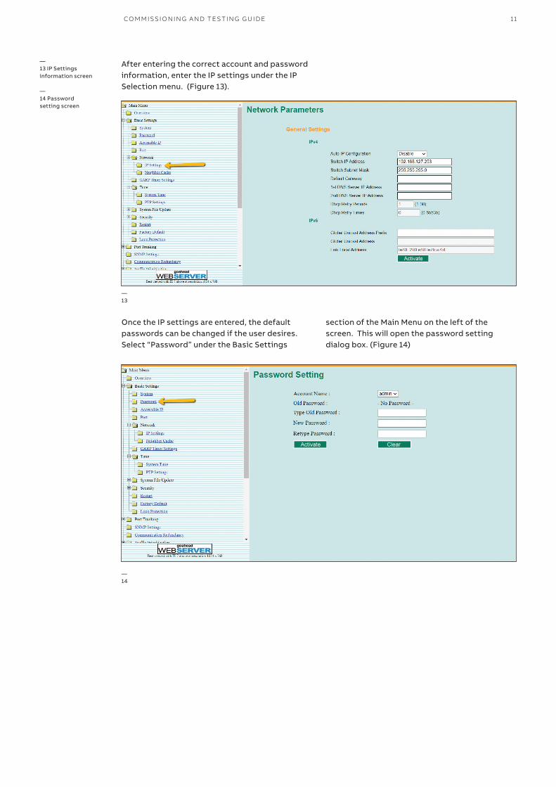
Once the IP settings are entered, the default passwords can be changed if the user desires. Select “Password” under the Basic Settings
—13
—14
—13 IP Settings information screen
—14 Password setting screen
After entering the correct account and password information, enter the IP settings under the IP Selection menu. (Figure 13).
section of the Main Menu on the left of the screen. This will open the password setting dialog box. (Figure 14)
12 ANSI MEDIUM VOLTAGE METAL-CLAD DIGITAL SWITCHGEAR
—15
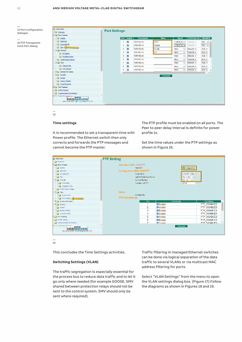
—15 Port configuration dialogue
—16 PTP Transparent clock Port dialog
Time settings
It is recommended to set a transparent time with Power profile. The Ethernet switch then only corrects and forwards the PTP messages and cannot become the PTP master.
This concludes the Time Settings activities.
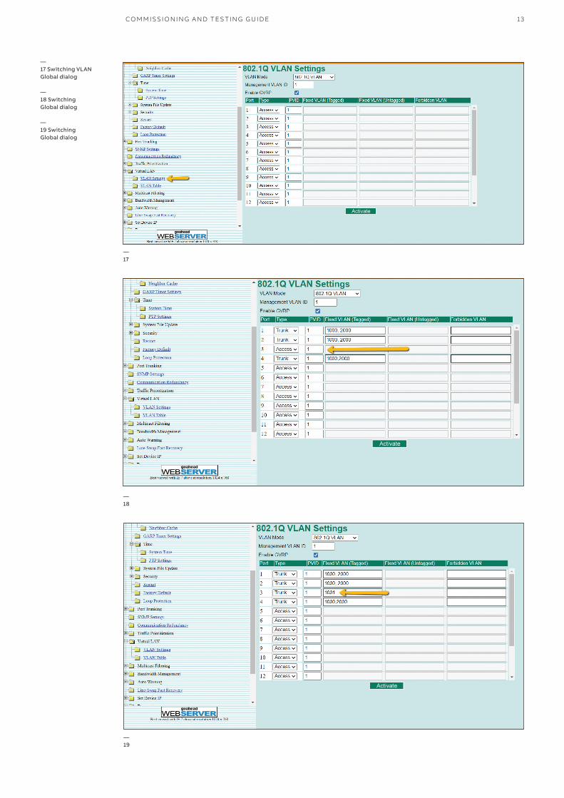
Switching Settings (VLAN)
The traffic segregation is especially essential for the process bus to reduce data traffic and to let it go only where needed (for example GOOSE, SMV shared between protection relays should not be sent to the control system, SMV should only be sent where required).
—16
Traffic filtering in managed Ethernet switches can be done via logical separation of the data traffic to several VLANs or via multicast MAC address filtering for ports.
Select “VLAN Settings” from the menu to open the VLAN settings dialog box. (Figure 17) Follow the diagrams as shown in Figures 18 and 19.
The PTP profile must be enabled on all ports. The Peer to peer delay interval is definite for power profile 1s.
Set the time values under the PTP settings as shown in Figure 16.
CO M M ISSI O N I N G A N D TE S TI N G G U I D E 13
—17
—18
—17 Switching VLAN Global dialog
—18 Switching Global dialog
—19 Switching Global dialog
—19
14 ANSI MEDIUM VOLTAGE METAL-CLAD DIGITAL SWITCHGEAR
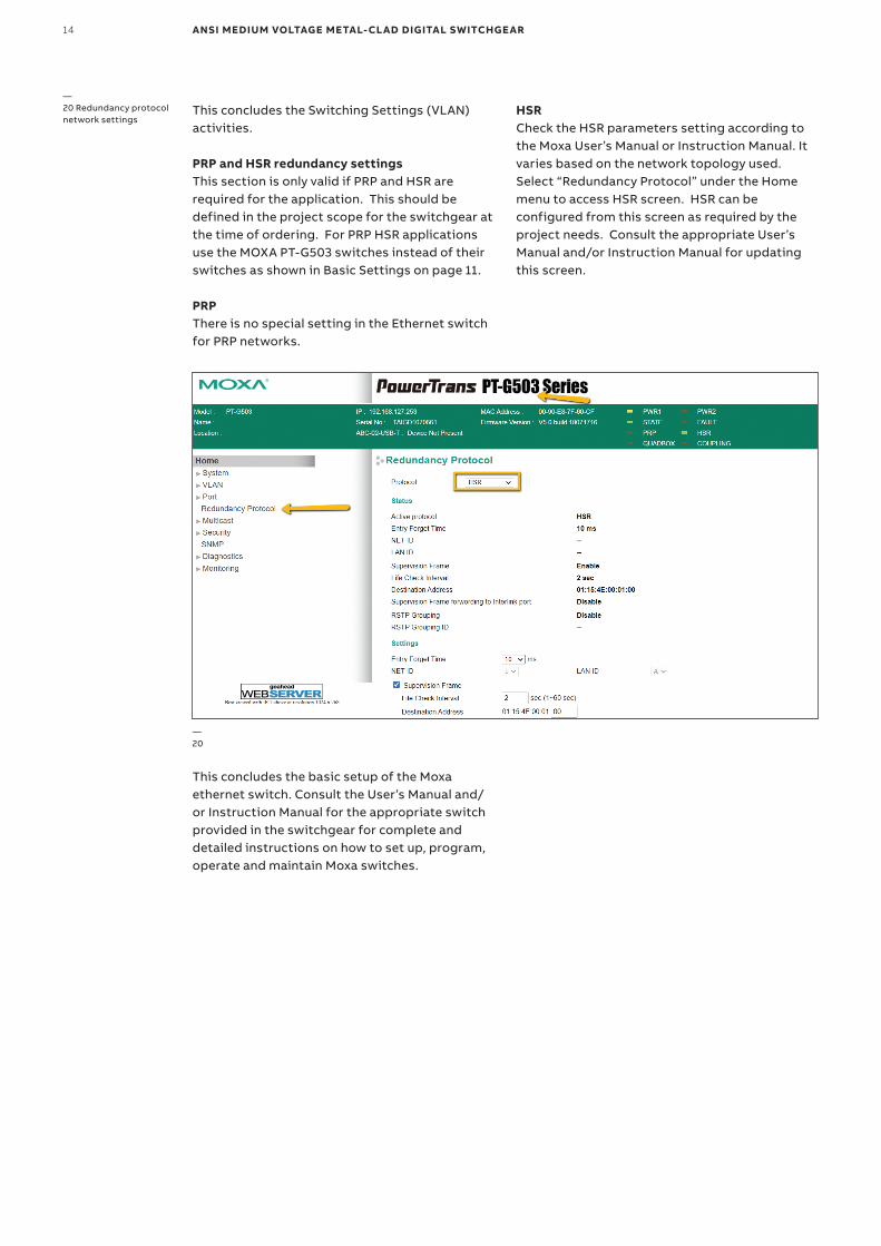
This concludes the Switching Settings (VLAN) activities.
PRP and HSR redundancy settingsThis section is only valid if PRP and HSR are required for the application. This should be defined in the project scope for the switchgear at the time of ordering. For PRP HSR applications use the MOXA PT-G503 switches instead of their switches as shown in Basic Settings on page 11.
PRPThere is no special setting in the Ethernet switch for PRP networks.
This concludes the basic setup of the Moxa ethernet switch. Consult the User’s Manual and/or Instruction Manual for the appropriate switch provided in the switchgear for complete and detailed instructions on how to set up, program, operate and maintain Moxa switches.
—20
—20 Redundancy protocol network settings
HSRCheck the HSR parameters setting according to the Moxa User’s Manual or Instruction Manual. It varies based on the network topology used.Select “Redundancy Protocol” under the Home menu to access HSR screen. HSR can be configured from this screen as required by the project needs. Consult the appropriate User’s Manual and/or Instruction Manual for updating this screen.
CO M M ISSI O N I N G A N D TE S TI N G G U I D E 15
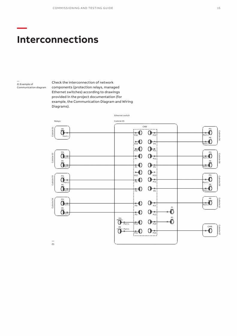
—Interconnections
Check the interconnection of network components (protection relays, managed Ethernet switches) according to drawings provided in the project documentation (for example, the Communication Diagram and Wiring Diagrams).
—21 Example of Communication diagram
PE
PG
PI
PJ
CMBPE
Port 1Port 1
Port 1
Port 1 Port 1
Port 1 Port 1
Port 1
Port 1 Port 1
Port 1 Port 1
Port 1
Port 1
Port 1 Port 1
Cu
bic
le 0
1
Cubicle 05
CNB
P10P16
P23P22
P13P3
P19P14
P10P15
P4P24
P12P6
P21P20
P6P2
P11P7
P17P9
P5P1
Cu
bic
le 0
2C
ub
icle
03
Cu
bic
le 0
4
PE
PE
PE
PE
PE
PE
PE
PG
PG
PG
PG
PG
PG
Cu
bicle 10
Cu
bicle 0
7C
ub
icle 09
Cu
bicle 0
8C
ub
icle 06
—21
Ethernet switch
Relays
16 ANSI MEDIUM VOLTAGE METAL-CLAD DIGITAL SWITCHGEAR
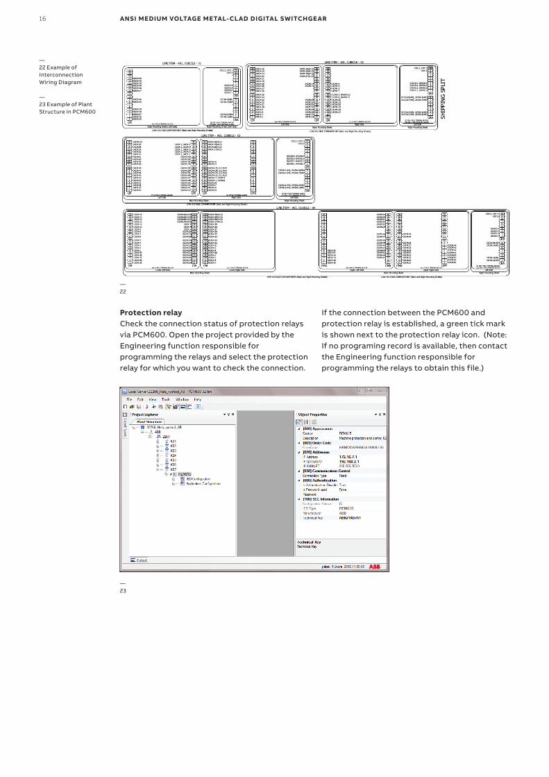
Protection relayCheck the connection status of protection relays via PCM600. Open the project provided by the Engineering function responsible for programming the relays and select the protection relay for which you want to check the connection.
—22
—23
—22 Example of Interconnection Wiring Diagram
—23 Example of Plant Structure in PCM600
If the connection between the PCM600 and protection relay is established, a green tick mark is shown next to the protection relay icon. (Note: If no programing record is available, then contact the Engineering function responsible for programming the relays to obtain this file.)
CO M M ISSI O N I N G A N D TE S TI N G G U I D E 17
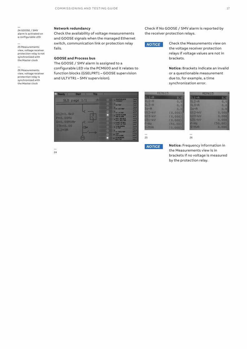
Network redundancyCheck the availability of voltage measurements and GOOSE signals when the managed Ethernet switch, communication link or protection relay fails.
GOOSE and Process busThe GOOSE / SMV alarm is assigned to a configurable LED via the PCM600 and it relates to function blocks (GSELPRT1 – GOOSE supervision and ULTVTR1 – SMV supervision).
—24
—25
—26
—24 GOOSE / SMV alarm is activated on a configurable LED
—25 Measurements view, voltage receiver protection relay is not synchronized with the Master clock
—26 Measurements view, voltage receiver protection relay is synchronized with the Master clock
Check the Measurements view on the voltage receiver protection relays if voltage values are not in brackets.
Notice: Brackets indicate an invalid or a questionable measurement due to, for example, a time synchronization error.
Notice: Frequency information in the Measurements view is in brackets if no voltage is measured by the protection relay.
NOTICE
NOTICE
Check if No GOOSE / SMV alarm is reported by the receiver protection relays.
18 ANSI MEDIUM VOLTAGE METAL-CLAD DIGITAL SWITCHGEAR
All current and voltage sensors can remain connected to the bus during power frequency (bus hipot) and secondary wire dielectric testing.Primary testing is valuable for verification of the whole measurement chain in the application including switching equipment (circuit breaker or contactor). The measuring chain includes the sensor, cable connections and settings of the protection relay.
Digital solution vs. traditional switchgearThe following applies in the case of digital switchgear:• No complex checks of inter-panel wiring are
required• Ethernet network fault detection is available• Higher protection relay engineering skills are
required in case of modifications• Relay configuration modifications can be
performed using the free downloadable PCM600 software
• For pre-testing, secondary tester with sensor support (low voltage output signals) is required
• The setting of sensors in the protection relay is described in the Digital Switchgear Engineering guide 1VAL108402-TG Rev A
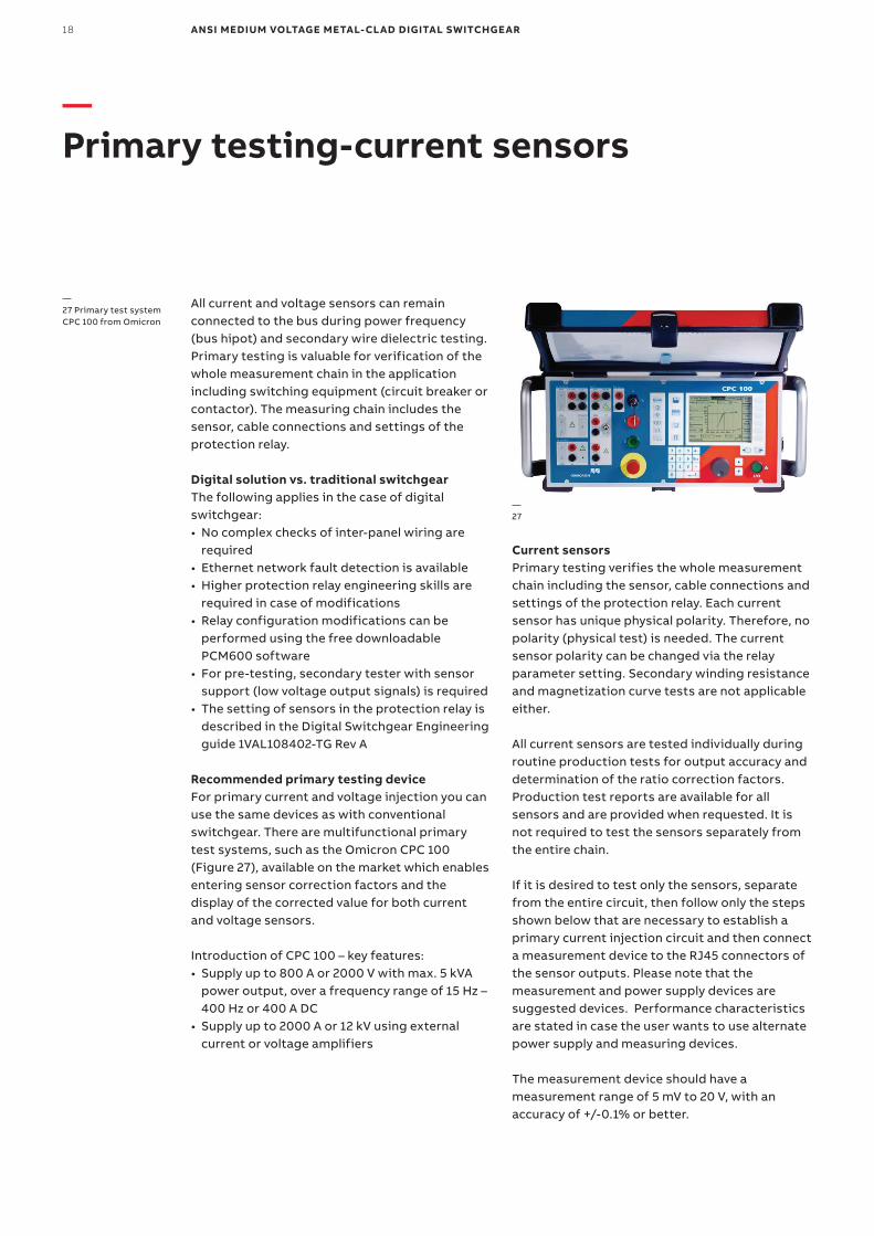
Recommended primary testing deviceFor primary current and voltage injection you can use the same devices as with conventional switchgear. There are multifunctional primary test systems, such as the Omicron CPC 100 (Figure 27), available on the market which enables entering sensor correction factors and the display of the corrected value for both current and voltage sensors.
Introduction of CPC 100 – key features:• Supply up to 800 A or 2000 V with max. 5 kVA
power output, over a frequency range of 15 Hz – 400 Hz or 400 A DC
• Supply up to 2000 A or 12 kV using external current or voltage amplifiers
Current sensorsPrimary testing verifies the whole measurement chain including the sensor, cable connections and settings of the protection relay. Each current sensor has unique physical polarity. Therefore, no polarity (physical test) is needed. The current sensor polarity can be changed via the relay parameter setting. Secondary winding resistance and magnetization curve tests are not applicable either.
All current sensors are tested individually during routine production tests for output accuracy and determination of the ratio correction factors. Production test reports are available for all sensors and are provided when requested. It is not required to test the sensors separately from the entire chain.
If it is desired to test only the sensors, separate from the entire circuit, then follow only the steps shown below that are necessary to establish a primary current injection circuit and then connect a measurement device to the RJ45 connectors of the sensor outputs. Please note that the measurement and power supply devices are suggested devices. Performance characteristics are stated in case the user wants to use alternate power supply and measuring devices.
The measurement device should have a measurement range of 5 mV to 20 V, with an accuracy of +/-0.1% or better.
—27
—27 Primary test system CPC 100 from Omicron
—Primary testing-current sensors
CO M M ISSI O N I N G A N D TE S TI N G G U I D E 19
All current sensors are factory tested for accuracy in the continues primary current operating range, i.e., from 5% of rated primary current (4 A) up to the continues thermal current Icth (4000 A). These routine tests are made as per the requirements of the sensor standards IEC 60044-8 or IEC 61869-10.
The test value is 80 A which represents a rated primary current. Other primary current input values can be used. However, since sensors are linear in performance then it is not necessary to test all primary inputs. If the 80 A primary test results are within range, then the outputs for the other primary inputs will be in range.
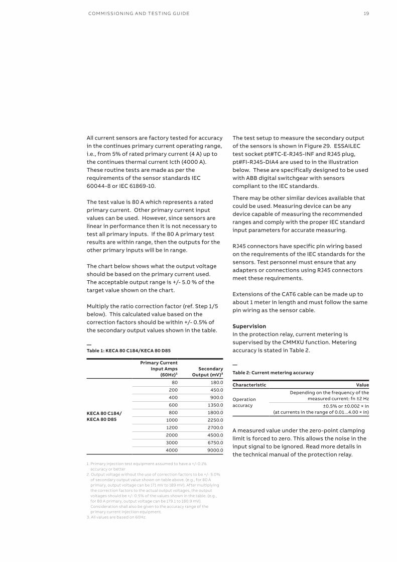
The chart below shows what the output voltage should be based on the primary current used. The acceptable output range is +/- 5.0 % of the target value shown on the chart.
Multiply the ratio correction factor (ref. Step 1/5 below). This calculated value based on the correction factors should be within +/- 0.5% of the secondary output values shown in the table.
—Table 1: KECA 80 C184/KECA 80 D85
Primary Current Input Amps
(60Hz)¹Secondary
Output (mV)²
KECA 80 C184/KECA 80 D85
80 180.0
200 450.0
400 900.0
600 1350.0
800 1800.0
1000 2250.0
1200 2700.0
2000 4500.0
3000 6750.0
4000 9000.0
1. Primary injection test equipment assumed to have a +/-0.1%accuracy or better
2. Output voltage without the use of correction factors to be +/- 5.0% of secondary output value shown on table above. (e.g., for 80 A primary, output voltage can be 171 mV to 189 mV). After multiplying the correction factors to the actual output voltages, the output voltages should be +/- 0.5% of the values shown in the table. (e.g., for 80 A primary, output voltage can be 179.1 to 180.9 mV). Consideration shall also be given to the accuracy range of the primary current injection equipment.
3. All values are based on 60Hz.
The test setup to measure the secondary output of the sensors is shown in Figure 29. ESSAILEC test socket pt#TC-E-RJ45-INF and RJ45 plug, pt#FI-RJ45-DIA4 are used to in the illustration below. These are specifically designed to be used with ABB digital switchgear with sensors compliant to the IEC standards.
There may be other similar devices available that could be used. Measuring device can be any device capable of measuring the recommended ranges and comply with the proper IEC standard input parameters for accurate measuring.
RJ45 connectors have specific pin wiring based on the requirements of the IEC standards for the sensors. Test personnel must ensure that any adapters or connections using RJ45 connectors meet these requirements.
Extensions of the CAT6 cable can be made up to about 1 meter in length and must follow the same pin wiring as the sensor cable.
SupervisionIn the protection relay, current metering is supervised by the CMMXU function. Metering accuracy is stated in Table 2.
—
Table 2: Current metering accuracy
Characteristic Value
Operation accuracy
Depending on the frequency of the measured current: fn ±2 Hz
±0.5% or ±0.002 × In (at currents in the range of 0.01...4.00 × In)
A measured value under the zero-point clamping limit is forced to zero. This allows the noise in the input signal to be ignored. Read more details in the technical manual of the protection relay.
20 ANSI MEDIUM VOLTAGE METAL-CLAD DIGITAL SWITCHGEAR
DANGER
WARNING
CAUTION
NOTICE
SAFETYINSTRUCTIONS
—Table 3: Zero-clamping limits
Function Zero-clamping limit
Three-phase current measurement (CMMXU) 1% of nominal (In)
Residual current measurement (RESCMMXU) 1% of nominal (In)
Phase sequence current meas. (CSMSQI) 1% of nominal (In)
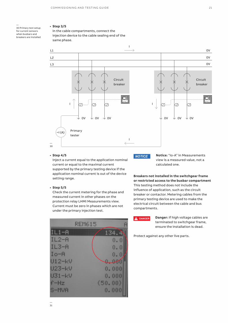
Main bus and breakers installed in the switchgear frameThis testing procedure includes the influence of applications such as the circuit breaker or contactor. Installed busbars are used to make the electrical circuit between two neighboring frames.
Danger: If high voltage cables are terminated to switchgear frame, ensure the installation is dead.Protect against any other live parts.
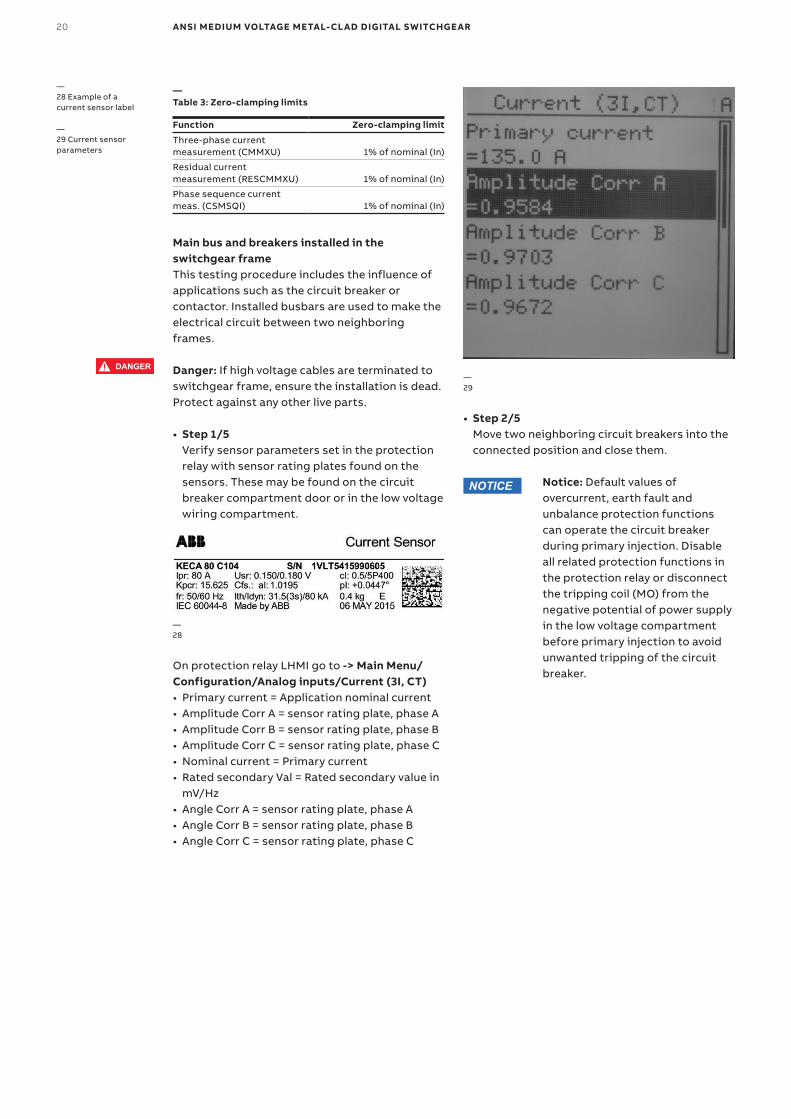
• Step 1/5 Verify sensor parameters set in the protection relay with sensor rating plates found on the sensors. These may be found on the circuit breaker compartment door or in the low voltage wiring compartment.
—28
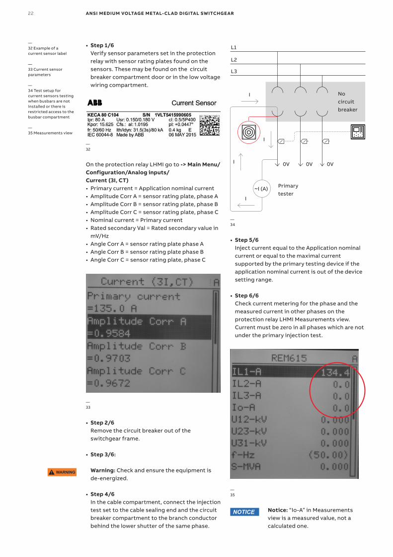
—28 Example of a current sensor label
—29 Current sensor parameters
On protection relay LHMI go to -> Main Menu/Configuration/Analog inputs/Current (3I, CT)• Primary current = Application nominal current• Amplitude Corr A = sensor rating plate, phase A• Amplitude Corr B = sensor rating plate, phase B• Amplitude Corr C = sensor rating plate, phase C• Nominal current = Primary current• Rated secondary Val = Rated secondary value in
mV/Hz• Angle Corr A = sensor rating plate, phase A• Angle Corr B = sensor rating plate, phase B• Angle Corr C = sensor rating plate, phase C
• Step 2/5 Move two neighboring circuit breakers into the connected position and close them.
Notice: Default values of overcurrent, earth fault and unbalance protection functions can operate the circuit breaker during primary injection. Disable all related protection functions in the protection relay or disconnect the tripping coil (MO) from the negative potential of power supply in the low voltage compartment before primary injection to avoid unwanted tripping of the circuit breaker.
—29
NOTICE
CO M M ISSI O N I N G A N D TE S TI N G G U I D E 21
• Step 3/5 In the cable compartments, connect the injection device to the cable sealing end of the same phase.
• Step 4/5 Inject a current equal to the application nominal current or equal to the maximal current supported by the primary testing device if the application nominal current is out of the device setting range.
• Step 5/5 Check the current metering for the phase and measured current in other phases on the protection relay LHMI Measurements view.Current must be zero in phases which are not under the primary injection test.
Breakers not installed in the switchgear frame or restricted access to the busbar compartmentThis testing method does not include the influence of application, such as the circuit breaker or contactor. Metering cables from the primary testing device are used to make the electrical circuit between the cable and bus compartments.
Danger: If high voltage cables are terminated to switchgear frame, ensure the installation is dead.
Protect against any other live parts.
—30 Primary test setup for current sensors when busbars and breakers are installed
NOTICE
Circuit breaker
Circuit breaker
0V 0V0V 0V0V 0V
Primary tester
~I (A)
0VL1I
I
I I
0VL2
0VL3
—30
—31
Notice: “Io-A” in Measurements view is a measured value, not a calculated one.
DANGER
WARNING
CAUTION
NOTICE
SAFETYINSTRUCTIONS
22 ANSI MEDIUM VOLTAGE METAL-CLAD DIGITAL SWITCHGEAR
• Step 1/6 Verify sensor parameters set in the protection relay with sensor rating plates found on the sensors. These may be found on the circuit breaker compartment door or in the low voltage wiring compartment.
• Step 2/6 Remove the circuit breaker out of the switchgear frame.
• Step 3/6: Warning: Check and ensure the equipment is de-energized.
• Step 4/6 In the cable compartment, connect the injection test set to the cable sealing end and the circuit breaker compartment to the branch conductor behind the lower shutter of the same phase.
• Step 5/6 Inject current equal to the Application nominal current or equal to the maximal current supported by the primary testing device if the application nominal current is out of the device setting range.
• Step 6/6 Check current metering for the phase and the measured current in other phases on the protection relay LHMI Measurements view.Current must be zero in all phases which are not under the primary injection test.
Notice: “Io-A” in Measurements view is a measured value, not a calculated one.
On the protection relay LHMI go to -> Main Menu/Configuration/Analog inputs/ Current (3I, CT)• Primary current = Application nominal current• Amplitude Corr A = sensor rating plate, phase A• Amplitude Corr B = sensor rating plate, phase B• Amplitude Corr C = sensor rating plate, phase C• Nominal current = Primary current• Rated secondary Val = Rated secondary value in
mV/Hz• Angle Corr A = sensor rating plate phase A• Angle Corr B = sensor rating plate phase B• Angle Corr C = sensor rating plate, phase C
—32
—33
—35
—34
—32 Example of a current sensor label
—33 Current sensor parameters
—34 Test setup for current sensors testing when busbars are not installed or there is restricted access to the busbar compartment
—35 Measurements view
WARNING
NOTICE
L1
L2
L3
No circuit breaker
0V 0V 0V
I
I
Primary tester
~I (A)
I
I
CO M M ISSI O N I N G A N D TE S TI N G G U I D E 23
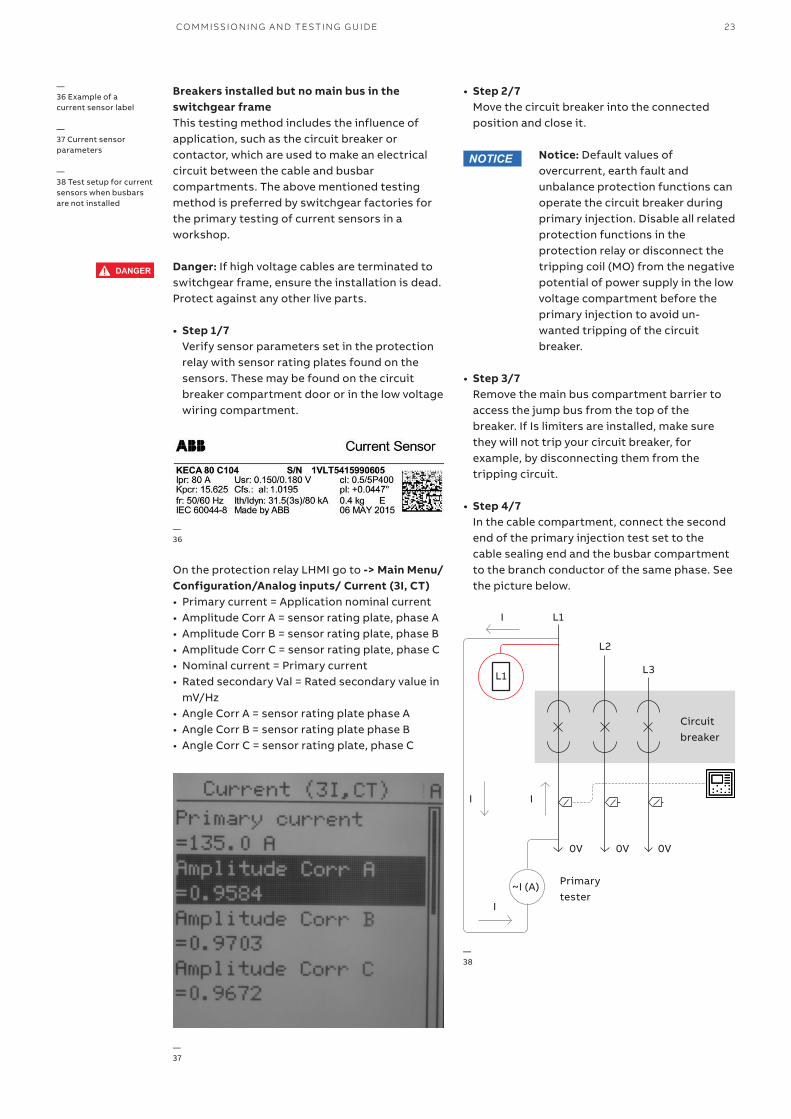
Breakers installed but no main bus in the switchgear frameThis testing method includes the influence of application, such as the circuit breaker or contactor, which are used to make an electrical circuit between the cable and busbar compartments. The above mentioned testing method is preferred by switchgear factories for the primary testing of current sensors in a workshop.
Danger: If high voltage cables are terminated to switchgear frame, ensure the installation is dead.Protect against any other live parts.
• Step 1/7 Verify sensor parameters set in the protection relay with sensor rating plates found on the sensors. These may be found on the circuit breaker compartment door or in the low voltage wiring compartment.
• Step 2/7 Move the circuit breaker into the connected position and close it.
Notice: Default values of overcurrent, earth fault and unbalance protection functions can operate the circuit breaker during primary injection. Disable all related protection functions in the protection relay or disconnect the tripping coil (MO) from the negative potential of power supply in the low voltage compartment before the primary injection to avoid un-wanted tripping of the circuit breaker.
• Step 3/7 Remove the main bus compartment barrier to access the jump bus from the top of the breaker. If Is limiters are installed, make sure they will not trip your circuit breaker, for example, by disconnecting them from the tripping circuit.
• Step 4/7 In the cable compartment, connect the second end of the primary injection test set to the cable sealing end and the busbar compartment to the branch conductor of the same phase. See the picture below.
On the protection relay LHMI go to -> Main Menu/Configuration/Analog inputs/ Current (3I, CT)• Primary current = Application nominal current• Amplitude Corr A = sensor rating plate, phase A• Amplitude Corr B = sensor rating plate, phase B• Amplitude Corr C = sensor rating plate, phase C• Nominal current = Primary current• Rated secondary Val = Rated secondary value in
mV/Hz• Angle Corr A = sensor rating plate phase A• Angle Corr B = sensor rating plate phase B• Angle Corr C = sensor rating plate, phase C
—36
—37
—38
—36 Example of a current sensor label
—37 Current sensor parameters
—38 Test setup for current sensors when busbars are not installed
DANGER
WARNING
CAUTION
NOTICE
SAFETYINSTRUCTIONS
NOTICE
L1
L1
L2
L3
Circuit breaker
0V 0V 0V
II
Primary tester
~I (A)
I
I
24 ANSI MEDIUM VOLTAGE METAL-CLAD DIGITAL SWITCHGEAR
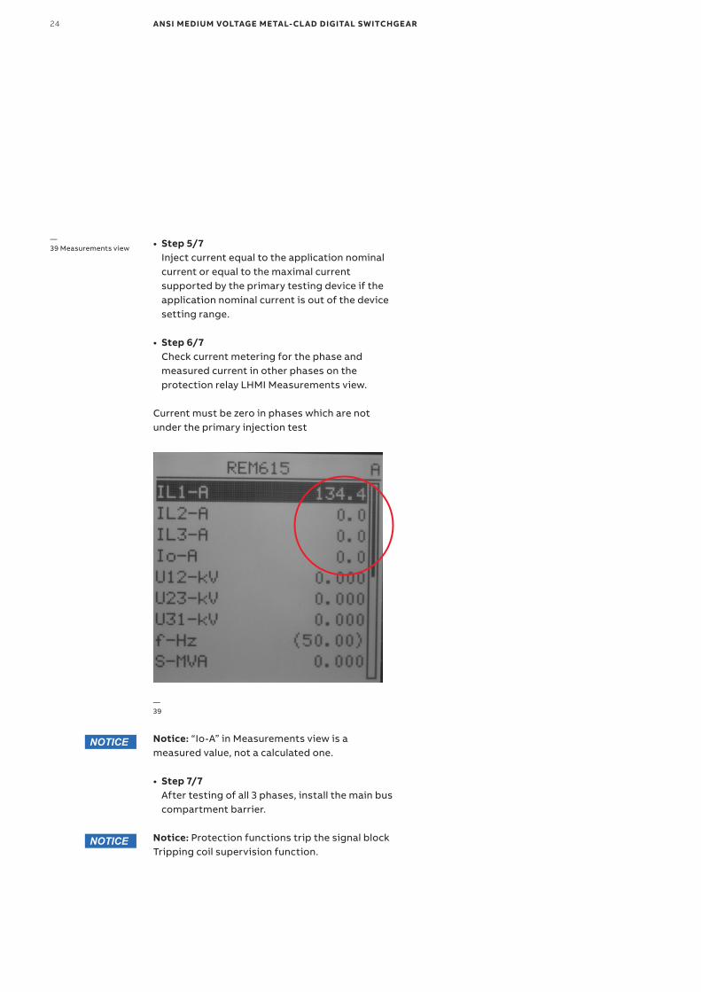
• Step 6/7 Check current metering for the phase and measured current in other phases on the protection relay LHMI Measurements view.
Current must be zero in phases which are not under the primary injection test
Notice: Protection functions trip the signal block Tripping coil supervision function.
—39
—39 Measurements view
Notice: “Io-A” in Measurements view is a measured value, not a calculated one.
NOTICE
NOTICE
• Step 7/7 After testing of all 3 phases, install the main bus compartment barrier.
• Step 5/7 Inject current equal to the application nominal current or equal to the maximal current supported by the primary testing device if the application nominal current is out of the device setting range.
CO M M ISSI O N I N G A N D TE S TI N G G U I D E 25
—Primary testing-voltage sensors
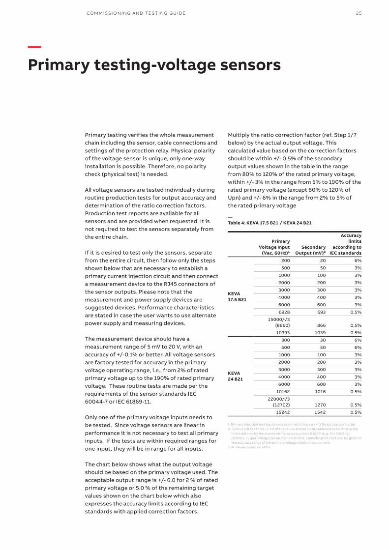
Primary testing verifies the whole measurement chain including the sensor, cable connections and settings of the protection relay. Physical polarity of the voltage sensor is unique, only one-way installation is possible. Therefore, no polarity check (physical test) is needed.
All voltage sensors are tested individually during routine production tests for output accuracy and determination of the ratio correction factors. Production test reports are available for all sensors and are provided when requested. It is not required to test the sensors separately from the entire chain.
If it is desired to test only the sensors, separate from the entire circuit, then follow only the steps shown below that are necessary to establish a primary current injection circuit and then connect a measurement device to the RJ45 connectors of the sensor outputs. Please note that the measurement and power supply devices are suggested devices. Performance characteristics are stated in case the user wants to use alternate power supply and measuring devices.
The measurement device should have a measurement range of 5 mV to 20 V, with an accuracy of +/-0.1% or better. All voltage sensors are factory tested for accuracy in the primary voltage operating range, i.e., from 2% of rated primary voltage up to the 190% of rated primary voltage. These routine tests are made per the requirements of the sensor standards IEC 60044-7 or IEC 61869-11.
Only one of the primary voltage inputs needs to be tested. Since voltage sensors are linear in performance it is not necessary to test all primary inputs. If the tests are within required ranges for one input, they will be in range for all inputs.
The chart below shows what the output voltage should be based on the primary voltage used. The acceptable output range is +/- 6.0 for 2 % of rated primary voltage or 5.0 % of the remaining target values shown on the chart below which also expresses the accuracy limits according to IEC standards with applied correction factors.
Multiply the ratio correction factor (ref. Step 1/7 below) by the actual output voltage. This calculated value based on the correction factors should be within +/- 0.5% of the secondary output values shown in the table in the range from 80% to 120% of the rated primary voltage, within +/- 3% in the range from 5% to 190% of the rated primary voltage (except 80% to 120% of Upn) and +/- 6% in the range from 2% to 5% of the rated primary voltage
Primary Voltage Input
(Vac, 60Hz)¹Secondary
Output (mV)²
Accuracy limits
according to IEC standards
KEVA 17.5 B21
200 20 6%
500 50 3%
1000 100 3%
2000 200 3%
3000 300 3%
4000 400 3%
6000 600 3%
6928 693 0.5%
15000/√3 (8660) 866 0.5%
10393 1039 0.5%
KEVA 24 B21
300 30 6%
500 50 6%
1000 100 3%
2000 200 3%
3000 300 3%
4000 400 3%
6000 600 3%
10162 1016 0.5%
22000/√3 (12702) 1270 0.5%
15242 1542 0.5%
—Table 4: KEVA 17.5 B21 / KEVA 24 B21
1. Primary injection test equipment assumed to have a +/-0.1% accuracy or better4. Output voltage to be +/-x% of the values shown in the table and according to the
limits defined by the standards for accuracy class 0.5/3P. (e.g., for 8660 Vac primary, output voltage can be 862 to 870 mV). Consideration shall also be given to the accuracy range of the primary voltage injection equipment.
5. All values based on 60Hz.
26 ANSI MEDIUM VOLTAGE METAL-CLAD DIGITAL SWITCHGEAR
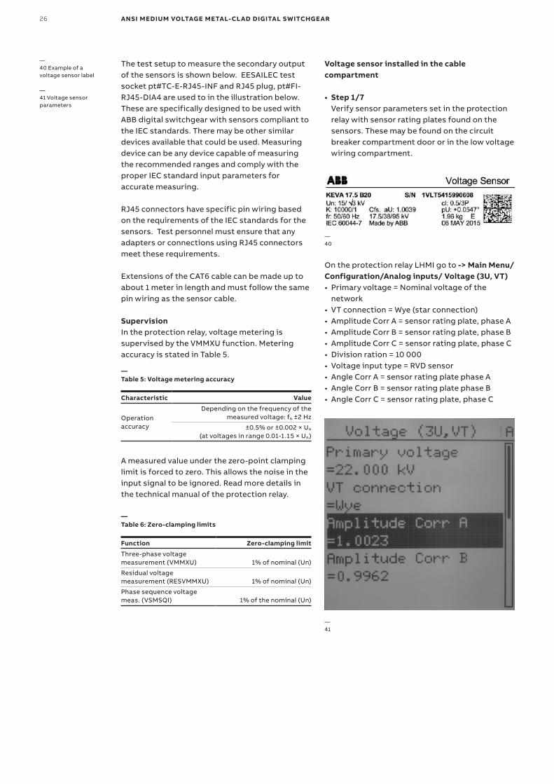
The test setup to measure the secondary output of the sensors is shown below. EESAILEC test socket pt#TC-E-RJ45-INF and RJ45 plug, pt#FI-RJ45-DIA4 are used to in the illustration below. These are specifically designed to be used with ABB digital switchgear with sensors compliant to the IEC standards. There may be other similar devices available that could be used. Measuring device can be any device capable of measuring the recommended ranges and comply with the proper IEC standard input parameters for accurate measuring.
RJ45 connectors have specific pin wiring based on the requirements of the IEC standards for the sensors. Test personnel must ensure that any adapters or connections using RJ45 connectors meet these requirements.
Extensions of the CAT6 cable can be made up to about 1 meter in length and must follow the same pin wiring as the sensor cable.
SupervisionIn the protection relay, voltage metering is supervised by the VMMXU function. Metering accuracy is stated in Table 5.
A measured value under the zero-point clamping limit is forced to zero. This allows the noise in the input signal to be ignored. Read more details in the technical manual of the protection relay.
—Table 5: Voltage metering accuracy
Characteristic Value
Operation accuracy
Depending on the frequency of the measured voltage: fn ±2 Hz
±0.5% or ±0.002 × Un (at voltages in range 0.01-1.15 × Un)
Voltage sensor installed in the cable compartment
• Step 1/7 Verify sensor parameters set in the protection relay with sensor rating plates found on the sensors. These may be found on the circuit breaker compartment door or in the low voltage wiring compartment.
—40
—41
—Table 6: Zero-clamping limits
Function Zero-clamping limit
Three-phase voltage measurement (VMMXU) 1% of nominal (Un)
Residual voltage measurement (RESVMMXU) 1% of nominal (Un)
Phase sequence voltage meas. (VSMSQI) 1% of the nominal (Un)
On the protection relay LHMI go to -> Main Menu/Configuration/Analog inputs/ Voltage (3U, VT)• Primary voltage = Nominal voltage of the
network• VT connection = Wye (star connection)• Amplitude Corr A = sensor rating plate, phase A• Amplitude Corr B = sensor rating plate, phase B• Amplitude Corr C = sensor rating plate, phase C• Division ration = 10 000• Voltage input type = RVD sensor• Angle Corr A = sensor rating plate phase A• Angle Corr B = sensor rating plate phase B• Angle Corr C = sensor rating plate, phase C
—40 Example of a voltage sensor label
—41 Voltage sensor parameters
CO M M ISSI O N I N G A N D TE S TI N G G U I D E 27
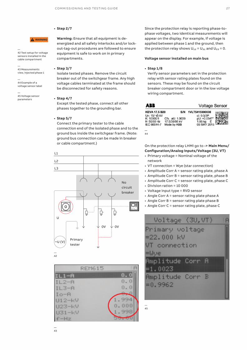
• Step 2/7 Warning: Ensure that all equipment is de-energized and all safety interlocks and/or lock-out-tag-out procedures are followed to ensure equipment is safe to work on in primary compartments.
• Step 3/7 Isolate tested phases. Remove the circuit breaker out of the switchgear frame. Any high voltage cables terminated at the frame should be disconnected for safety reasons.
• Step 4/7 Except the tested phase, connect all other phases together to the grounding bar.
• Step 5/7 Connect the primary tester to the cable connection end of the isolated phase and to the ground bus inside the switchgear frame. (Note: ground bus connection can be made in breaker or cable compartment.)
Since the protection relay is reporting phase-to-phase voltages, two identical measurements will appear on the display. For example, if voltage is applied between phase 1 and the ground, then the protection relay shows U₁₂ = U₃₁ and U₂₃ = 0.
Voltage sensor installed on main bus
• Step 1/8 Verify sensor parameters set in the protection relay with sensor rating plates found on the sensors. These may be found on the circuit breaker compartment door or in the low voltage wiring compartment.
WARNING
—42 Test setup for voltage sensors installed in the cable compartment
—43 Measurements view, injected phase 1
—44 Example of a voltage sensor label
—45 Voltage sensor parameters
—43
—42
—45
—44
On the protection relay LHMI go to -> Main Menu/Configuration/Analog inputs/Voltage (3U, VT)• Primary voltage = Nominal voltage of the
network• VT connection = Wye (star connection)• Amplitude Corr A = sensor rating plate, phase A• Amplitude Corr B = sensor rating plate, phase B• Amplitude Corr C = sensor rating plate, phase C• Division ration = 10 000• Voltage input type = RVD sensor• Angle Corr A = sensor rating plate phase A• Angle Corr B = sensor rating plate phase B• Angle Corr C = sensor rating plate, phase C
L1
L2
L3
No circuit breaker
U
0V 0V
Primary tester
~U (V)
28 ANSI MEDIUM VOLTAGE METAL-CLAD DIGITAL SWITCHGEAR
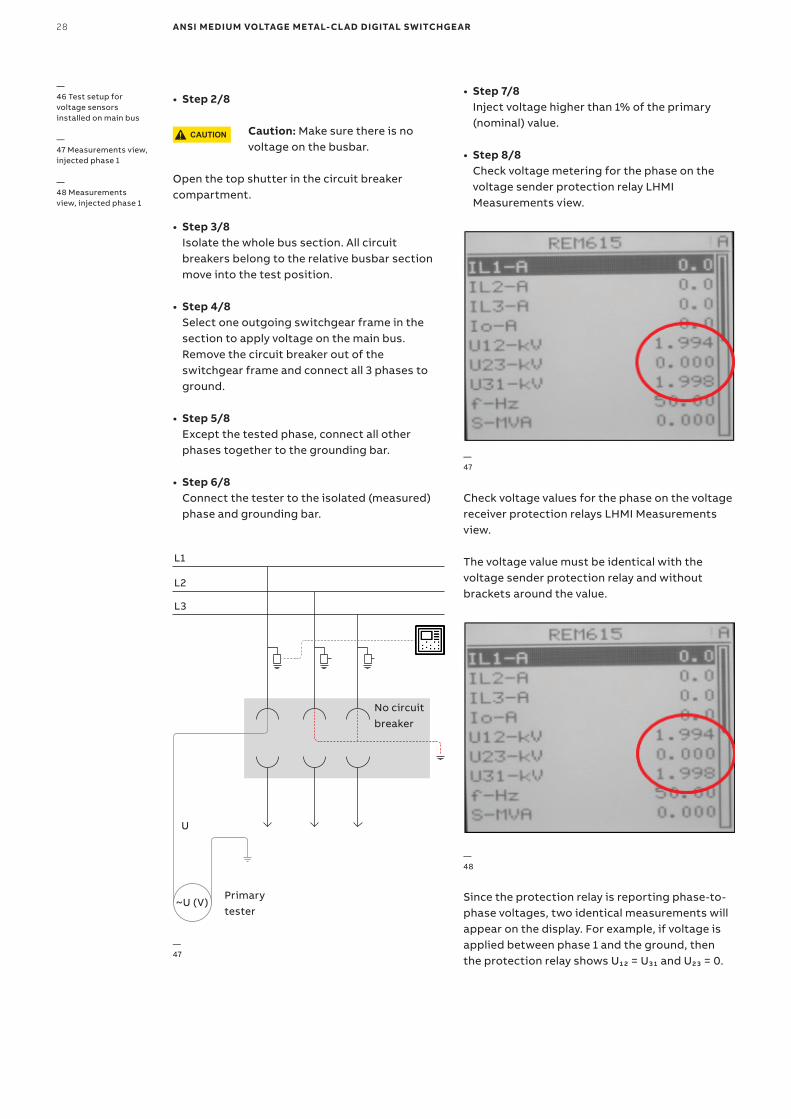
• Step 3/8 Isolate the whole bus section. All circuit breakers belong to the relative busbar section move into the test position.
• Step 4/8 Select one outgoing switchgear frame in the section to apply voltage on the main bus. Remove the circuit breaker out of the switchgear frame and connect all 3 phases to ground.
• Step 5/8 Except the tested phase, connect all other phases together to the grounding bar.
• Step 6/8 Connect the tester to the isolated (measured) phase and grounding bar.
Check voltage values for the phase on the voltage receiver protection relays LHMI Measurements view.
The voltage value must be identical with the voltage sender protection relay and without brackets around the value.
Since the protection relay is reporting phase-to-phase voltages, two identical measurements will appear on the display. For example, if voltage is applied between phase 1 and the ground, then the protection relay shows U₁₂ = U₃₁ and U₂₃ = 0.
• Step 7/8 Inject voltage higher than 1% of the primary (nominal) value.
• Step 8/8 Check voltage metering for the phase on the voltage sender protection relay LHMI Measurements view.
—46 Test setup for voltage sensors installed on main bus
—47 Measurements view, injected phase 1
—48 Measurements view, injected phase 1
—47
—47
—48
• Step 2/8
Caution: Make sure there is no voltage on the busbar.
Open the top shutter in the circuit breaker compartment.
CAUTION
L1
L2
L3
No circuit breaker
U
Primary tester
~U (V)
CO M M ISSI O N I N G A N D TE S TI N G G U I D E 29
Circuit breaker
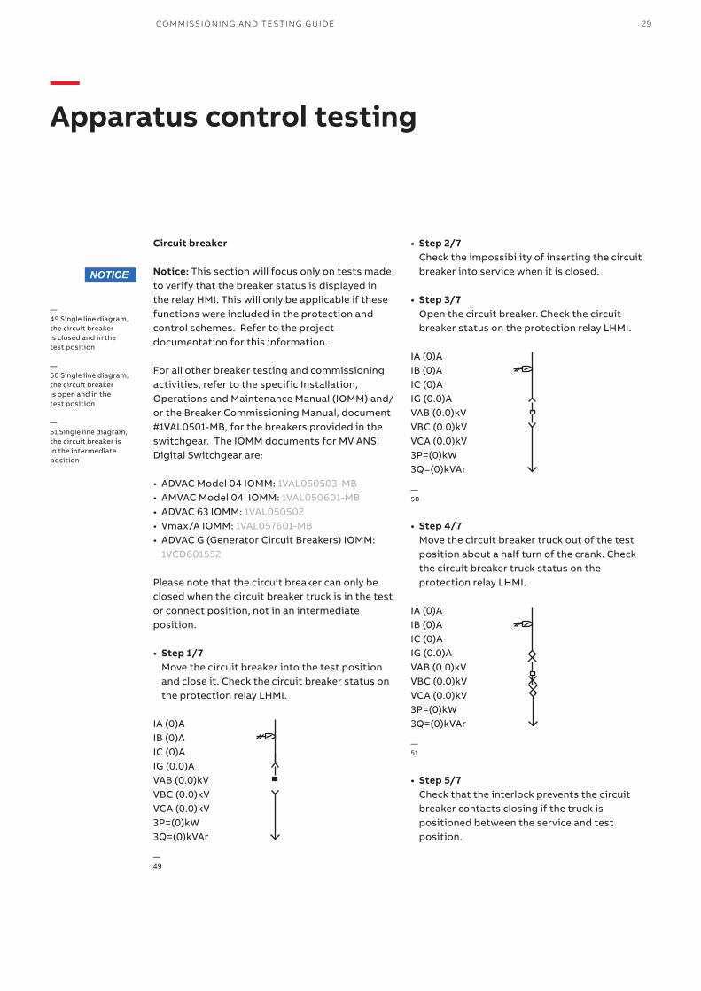
Notice: This section will focus only on tests made to verify that the breaker status is displayed in the relay HMI. This will only be applicable if these functions were included in the protection and control schemes. Refer to the project documentation for this information. For all other breaker testing and commissioning activities, refer to the specific Installation, Operations and Maintenance Manual (IOMM) and/or the Breaker Commissioning Manual, document #1VAL0501-MB, for the breakers provided in the switchgear. The IOMM documents for MV ANSI Digital Switchgear are:
• ADVAC Model 04 IOMM: 1VAL050503-MB• AMVAC Model 04 IOMM: 1VAL050601-MB• ADVAC 63 IOMM: 1VAL050502• Vmax/A IOMM: 1VAL057601-MB• ADVAC G (Generator Circuit Breakers) IOMM:
1VCD601552
Please note that the circuit breaker can only be closed when the circuit breaker truck is in the test or connect position, not in an intermediate position.
• Step 1/7 Move the circuit breaker into the test position and close it. Check the circuit breaker status on the protection relay LHMI.
IA (0)AIB (0)AIC (0)AIG (0.0)AVAB (0.0)kVVBC (0.0)kVVCA (0.0)kV3P=(0)kW3Q=(0)kVAr
• Step 2/7 Check the impossibility of inserting the circuit breaker into service when it is closed.
• Step 3/7 Open the circuit breaker. Check the circuit breaker status on the protection relay LHMI.
IA (0)AIB (0)AIC (0)AIG (0.0)AVAB (0.0)kVVBC (0.0)kVVCA (0.0)kV3P=(0)kW3Q=(0)kVAr
• Step 4/7 Move the circuit breaker truck out of the test position about a half turn of the crank. Check the circuit breaker truck status on the protection relay LHMI.
IA (0)AIB (0)AIC (0)AIG (0.0)AVAB (0.0)kVVBC (0.0)kVVCA (0.0)kV3P=(0)kW3Q=(0)kVAr
• Step 5/7 Check that the interlock prevents the circuit breaker contacts closing if the truck is positioned between the service and test position.
—Apparatus control testing
—49
—51
—50
—49 Single line diagram, the circuit breaker is closed and in the test position
—50 Single line diagram, the circuit breaker is open and in the test position
—51 Single line diagram, the circuit breaker is in the intermediate position
NOTICE
30 ANSI MEDIUM VOLTAGE METAL-CLAD DIGITAL SWITCHGEAR
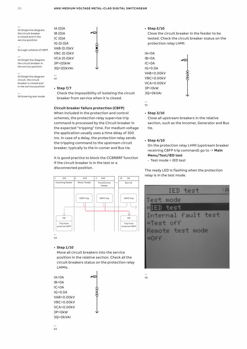
• Step 1/10 Move all circuit breakers into the service position in the relative section. Check all the circuit breakers status on the protection relay LHMIs.
IA=0AIB=0AIC=0AIG=0.0AVAB=0.00kVVBC=0.00kVVCA=0.00kV3P=0kW3Q=0kVAr
—54
• Step 2/10 Close the circuit breaker in the feeder to be tested. Check the circuit breaker status on the protection relay LHMI.
IA=0AIB=0AIC=0AIG=0.0AVAB=0.00kVVBC=0.00kVVCA=0.00kV3P=0kW3Q=0kVAr
—55
• Step 3/10 Close all upstream breakers in the relative section, such as the Incomer, Generator and Bus tie.
• Step 4/10 On the protection relay LHMI (upstream breaker receiving CBFP trip command) go to -> Main Menu/Test/IED test - Test mode = IED test
The ready LED is flashing when the protection relay is in the test mode.
—56
IA (0)AIB (0)AIC (0)AIG (0.0)AVAB (0.0)kVVBC (0.0)kVVCA (0.0)kV3P=(0)kW3Q=(0)kVAr
• Step 7/7 Check the impossibility of isolating the circuit breaker from service when it is closed.
Circuit breaker failure protection (CBFP)When included in the protection and control schemes, the protection relay supervise trip command is processed by the Circuit breaker in the expected “tripping” time. For medium voltage the application usually uses a time delay of 300 ms. In case of a delay, the protection relay sends the tripping command to the upstream circuit breaker, typically to the In-comer and Bus tie.
It is good practice to block the CCBRBRF function if the circuit breaker is in the test or a disconnected position.
—52 Single line diagram, the circuit breaker is closed and in the service position
—53 Logic scheme of CBFP
—54 Single line diagram, the circuit breaker in the service position
—53 Single line diagram circuit, the circuit breaker is closed and in the service position
—56 Entering test mode
—52
—53
A01
Incoming feeder Motor feeder Transformer feeder
Bus tie
CBFP trip
OR OR
Trip from external CBFP
Trip from external CBFP
CBFP trip CBFP trip
A02 A03 AB1 2 3 10
CO M M ISSI O N I N G A N D TE S TI N G G U I D E 31
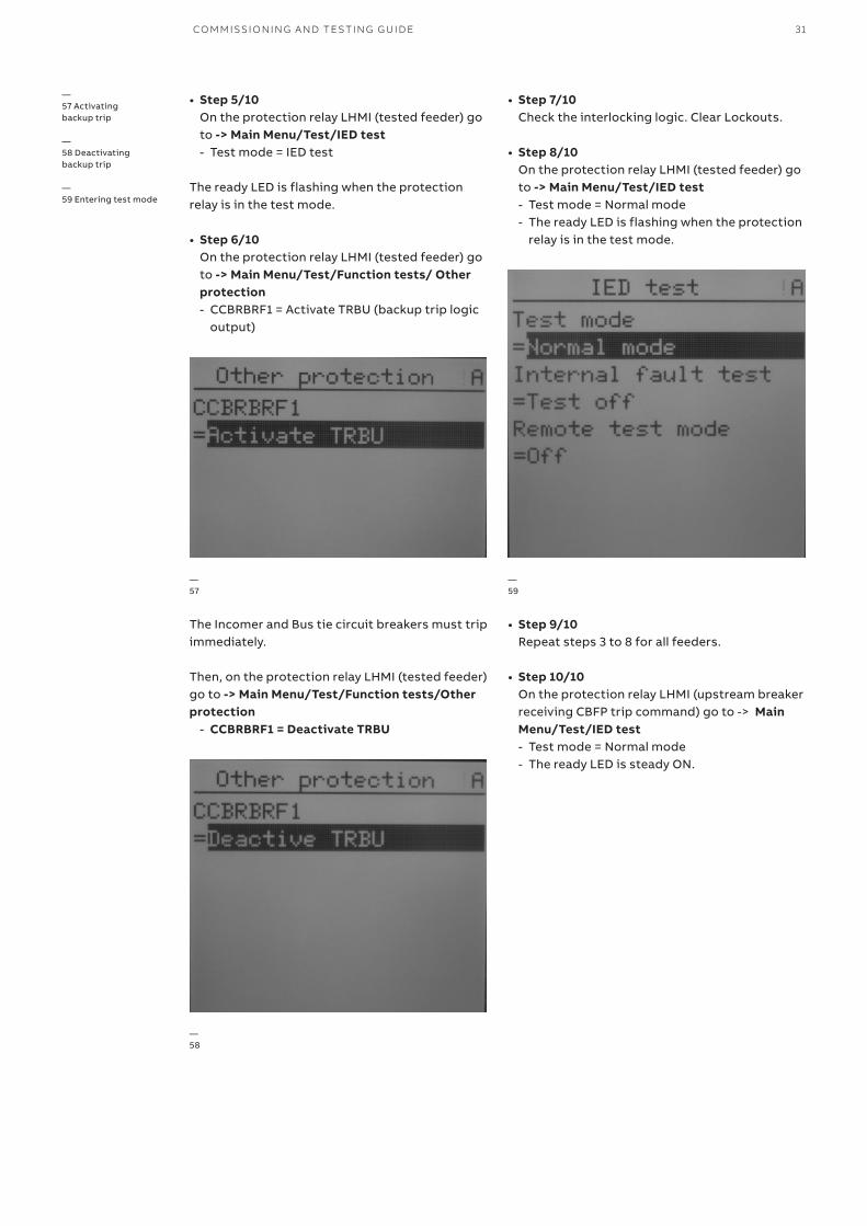
• Step 5/10 On the protection relay LHMI (tested feeder) go to -> Main Menu/Test/IED test - Test mode = IED test
The ready LED is flashing when the protection relay is in the test mode.
• Step 6/10 On the protection relay LHMI (tested feeder) go to -> Main Menu/Test/Function tests/ Other protection - CCBRBRF1 = Activate TRBU (backup trip logic
output)
• Step 7/10 Check the interlocking logic. Clear Lockouts.
• Step 8/10 On the protection relay LHMI (tested feeder) go to -> Main Menu/Test/IED test - Test mode = Normal mode - The ready LED is flashing when the protection
relay is in the test mode.
• Step 9/10 Repeat steps 3 to 8 for all feeders.
• Step 10/10 On the protection relay LHMI (upstream breaker receiving CBFP trip command) go to -> Main Menu/Test/IED test - Test mode = Normal mode - The ready LED is steady ON.
The Incomer and Bus tie circuit breakers must trip immediately.
Then, on the protection relay LHMI (tested feeder) go to -> Main Menu/Test/Function tests/Other protection
- CCBRBRF1 = Deactivate TRBU
—58
—59
—57
—57 Activating backup trip
—58 Deactivating backup trip
—59 Entering test mode
32 ANSI MEDIUM VOLTAGE METAL-CLAD DIGITAL SWITCHGEAR
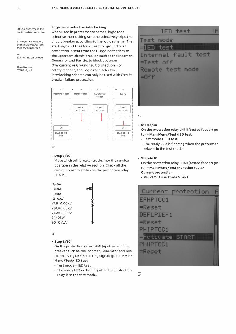
Logic zone selective interlockingWhen used in protection schemes, logic zone selective interlocking scheme selectively trips the circuit breaker according to the logic scheme. The start signal of the Overcurrent or ground fault protection is sent from the Outgoing feeders to the upstream circuit breaker, such as the Incomer, Generator and Bus tie, to block upstream Overcurrent or Ground fault protection. For safety reasons, the Logic zone selective interlocking scheme can only be used with Circuit breaker failure protection.
• Step 3/10 On the protection relay LHMI (tested feeder) go to -> Main Menu/Test/IED test - Test mode = IED test - The ready LED is flashing when the protection
relay is in the test mode.
• Step 4/10 On the protection relay LHMI (tested feeder) go to -> Main Menu/Test/Function tests/ Current protection - PHIPTOC1 = Activate START
• Step 1/10 Move all circuit breaker trucks into the service position in the relative section. Check all the circuit breakers status on the protection relay LHMIs.
IA=0AIB=0AIC=0AIG=0.0AVAB=0.00kVVBC=0.00kVVCA=0.00kV3P=0kW3Q=0kVAr
—61
• Step 2/10 On the protection relay LHMI (upstream circuit breaker such as the Incomer, Generator and Bus tie receiving LBBP blocking signal) go to -> Main Menu/Test/IED test - Test mode = IED test - The ready LED is flashing when the protection
relay is in the test mode.
—60 Logic scheme of the Logic busbar protection
—61 Single line diagram, the circuit breaker is in the service position
—62 Entering test mode
—63 Activating START signal
—60
—62
—63
A01
Incoming feeder Motor feeder Transformer feeder
Bus tie
50-OC inst. start
50-OC inst. start
50-OC inst. start
OR OR
Block 50-OC inst
Block 50-OC inst
A02 A03 AB1 2 3 10
CO M M ISSI O N I N G A N D TE S TI N G G U I D E 33
• Step 6/10 On the protection relay LHMI (tested feeder) go to -> Main Menu/Test/Function tests/ Current protection - PHIPTOC1 = Deactivate START
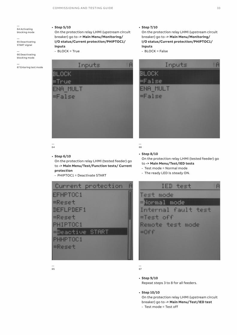
• Step 7/10 On the protection relay LHMI (upstream circuit breaker) go to -> Main Menu/Monitoring/ I/O status/Current protection/PHIPTOC1/Inputs - BLOCK = False
• Step 8/10 On the protection relay LHMI (tested feeder) go to -> Main Menu/Test/IED tests - Test mode = Normal mode - The ready LED is steady ON.
—65
—66
—67
—64 Activating blocking mode
—65 Deactivating START signal
—66 Deactivating blocking mode
—67 Entering test mode
• Step 9/10 Repeat steps 3 to 8 for all feeders.
• Step 10/10 On the protection relay LHMI (upstream circuit breaker) go to -> Main Menu/Test/IED test - Test mode = Test off
• Step 5/10 On the protection relay LHMI (upstream circuit breaker) go to -> Main Menu/Monitoring/ I/O status/Current protection/PHIPTOC1/Inputs - BLOCK = True
—64
34 ANSI MEDIUM VOLTAGE METAL-CLAD DIGITAL SWITCHGEAR
—68
—69
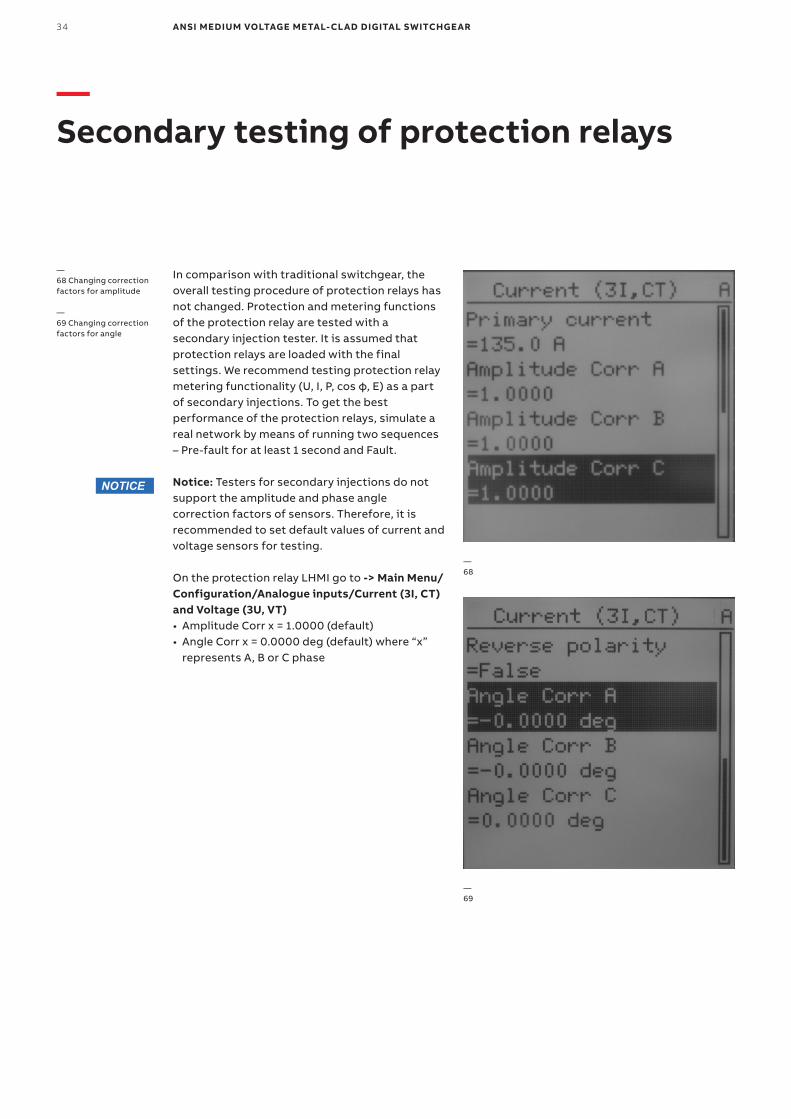
—68 Changing correction factors for amplitude
—69 Changing correction factors for angle
—Secondary testing of protection relays
In comparison with traditional switchgear, the overall testing procedure of protection relays has not changed. Protection and metering functions of the protection relay are tested with a secondary injection tester. It is assumed that protection relays are loaded with the final settings. We recommend testing protection relay metering functionality (U, I, P, cos φ, E) as a part of secondary injections. To get the best performance of the protection relays, simulate a real network by means of running two sequences – Pre-fault for at least 1 second and Fault.
Notice: Testers for secondary injections do not support the amplitude and phase angle correction factors of sensors. Therefore, it is recommended to set default values of current and voltage sensors for testing.
On the protection relay LHMI go to -> Main Menu/Configuration/Analogue inputs/Current (3I, CT) and Voltage (3U, VT)• Amplitude Corr x = 1.0000 (default)• Angle Corr x = 0.0000 deg (default) where “x”
represents A, B or C phase
NOTICE
CO M M ISSI O N I N G A N D TE S TI N G G U I D E 35
—FT-14D Flexitest switch
FT-14D digital test switches are used for efficient testing of protection and control relay during regular maintenance. The FT-14D test switch is usually supplied as a flush mounting type on the low voltage compartment door. The testing of protection and control relay's sensor inputs is possible without opening the low voltage compartment door.
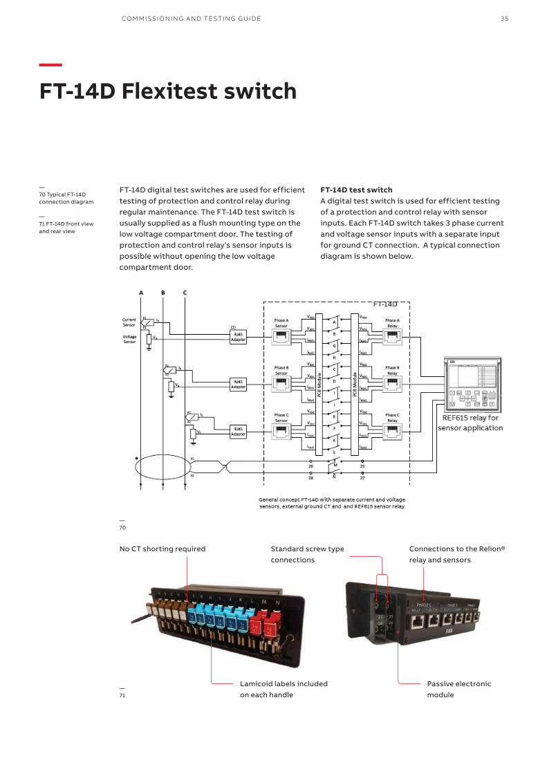
FT-14D test switchA digital test switch is used for efficient testing of a protection and control relay with sensor inputs. Each FT-14D switch takes 3 phase current and voltage sensor inputs with a separate input for ground CT connection. A typical connection diagram is shown below.
—70
—70 Typical FT-14D connection diagram
—71 FT-14D front view and rear view
—71
No CT shorting required Connections to the Relion® relay and sensors
Standard screw type connections
Lamicoid labels included on each handle
Passive electronic module
36 ANSI MEDIUM VOLTAGE METAL-CLAD DIGITAL SWITCHGEAR
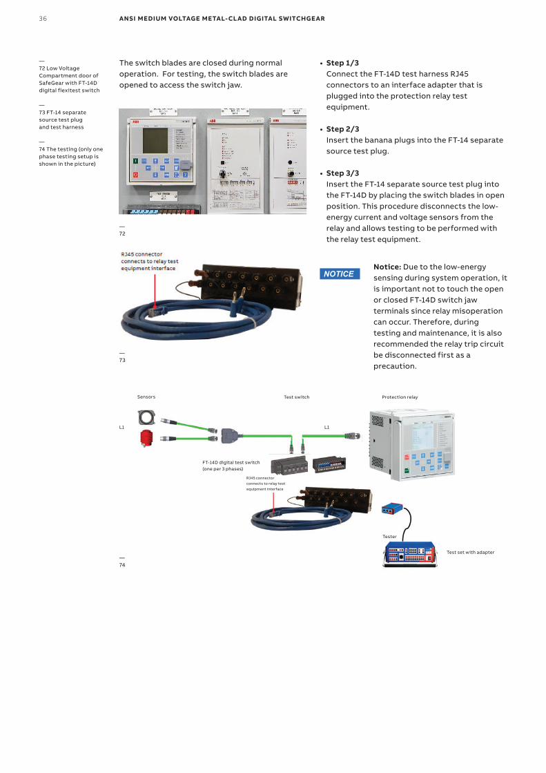
• Step 1/3 Connect the FT-14D test harness RJ45 connectors to an interface adapter that is plugged into the protection relay test equipment.
• Step 2/3 Insert the banana plugs into the FT-14 separate source test plug.
• Step 3/3 Insert the FT-14 separate source test plug into the FT-14D by placing the switch blades in open position. This procedure disconnects the low-energy current and voltage sensors from the relay and allows testing to be performed with the relay test equipment.
The switch blades are closed during normal operation. For testing, the switch blades are opened to access the switch jaw.
—72 Low Voltage Compartment door of SafeGear with FT-14D digital flexitest switch
—73 FT-14 separate source test plug and test harness
—74 The testing (only one phase testing setup is shown in the picture)
—72
—73
—74
Notice: Due to the low-energy sensing during system operation, it is important not to touch the open or closed FT-14D switch jaw terminals since relay misoperation can occur. Therefore, during testing and maintenance, it is also recommended the relay trip circuit be disconnected first as a precaution.
NOTICE
Sensors Test switch Protection relay
L1 L1
FT-14D digital test switch (one per 3 phases)
Tester
Test set with adapter
RJ45 connector connects to relay test equipment interface
CO M M ISSI O N I N G A N D TE S TI N G G U I D E 37
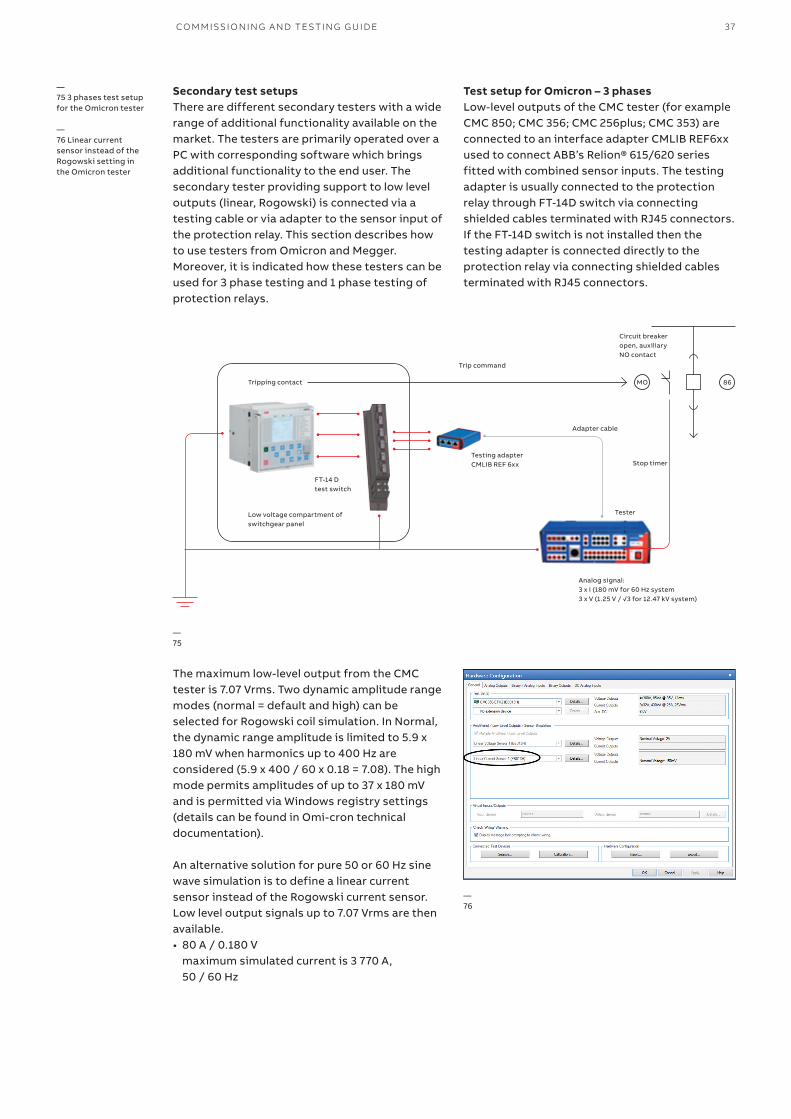
Secondary test setupsThere are different secondary testers with a wide range of additional functionality available on the market. The testers are primarily operated over a PC with corresponding software which brings additional functionality to the end user. The secondary tester providing support to low level outputs (linear, Rogowski) is connected via a testing cable or via adapter to the sensor input of the protection relay. This section describes how to use testers from Omicron and Megger. Moreover, it is indicated how these testers can be used for 3 phase testing and 1 phase testing of protection relays.
The maximum low-level output from the CMC tester is 7.07 Vrms. Two dynamic amplitude range modes (normal = default and high) can be selected for Rogowski coil simulation. In Normal, the dynamic range amplitude is limited to 5.9 x 180 mV when harmonics up to 400 Hz are considered (5.9 x 400 / 60 x 0.18 = 7.08). The high mode permits amplitudes of up to 37 x 180 mV and is permitted via Windows registry settings (details can be found in Omi-cron technical documentation).
An alternative solution for pure 50 or 60 Hz sine wave simulation is to define a linear current sensor instead of the Rogowski current sensor. Low level output signals up to 7.07 Vrms are then available.• 80 A / 0.180 V
maximum simulated current is 3 770 A, 50 / 60 Hz
Test setup for Omicron – 3 phasesLow-level outputs of the CMC tester (for example CMC 850; CMC 356; CMC 256plus; CMC 353) are connected to an interface adapter CMLIB REF6xx used to connect ABB’s Relion® 615/620 series fitted with combined sensor inputs. The testing adapter is usually connected to the protection relay through FT-14D switch via connecting shielded cables terminated with RJ45 connectors. If the FT-14D switch is not installed then the testing adapter is connected directly to the protection relay via connecting shielded cables terminated with RJ45 connectors.
—75
—76
—75 3 phases test setup for the Omicron tester
—76 Linear current sensor instead of the Rogowski setting in the Omicron tester
Tripping contact
FT-14 D test switch
Testing adapter CMLIB REF 6xx
Analog signal: 3 x I (180 mV for 60 Hz system3 x V (1.25 V / √3 for 12.47 kV system)
Circuit breaker open, auxiliary NO contact
Adapter cable
Stop timer
Trip command
Tester
86MO
Low voltage compartment of switchgear panel
38 ANSI MEDIUM VOLTAGE METAL-CLAD DIGITAL SWITCHGEAR
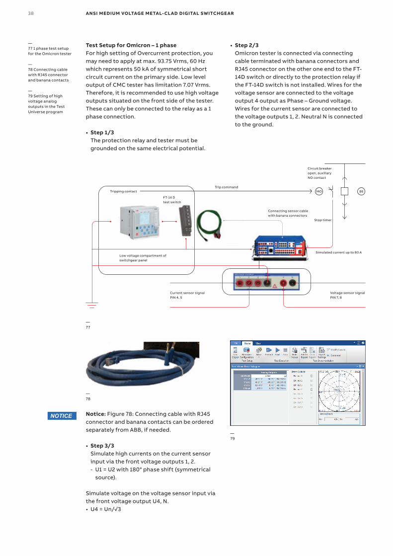
Test Setup for Omicron – 1 phaseFor high setting of Overcurrent protection, you may need to apply at max. 93.75 Vrms, 60 Hz which represents 50 kA of symmetrical short circuit current on the primary side. Low level output of CMC tester has limitation 7.07 Vrms. Therefore, it is recommended to use high voltage outputs situated on the front side of the tester. These can only be connected to the relay as a 1 phase connection.
• Step 1/3 The protection relay and tester must be grounded on the same electrical potential.
Notice: Figure 78: Connecting cable with RJ45 connector and banana contacts can be ordered separately from ABB, if needed.
• Step 3/3 Simulate high currents on the current sensor input via the front voltage outputs 1, 2. - U1 = U2 with 180° phase shift (symmetrical
source).
Simulate voltage on the voltage sensor input via the front voltage output U4, N.• U4 = Un/√3
—77
—78
—79
—77 1 phase test setup for the Omicron tester
—78 Connecting cable with RJ45 connector and banana contacts
—79 Setting of high voltage analog outputs in the Test Universe program
• Step 2/3 Omicron tester is connected via connecting cable terminated with banana connectors and RJ45 connector on the other one end to the FT-14D switch or directly to the protection relay if the FT-14D switch is not installed. Wires for the voltage sensor are connected to the voltage output 4 output as Phase – Ground voltage. Wires for the current sensor are connected to the voltage outputs 1, 2. Neutral N is connected to the ground.
NOTICE
Circuit breaker open, auxiliary NO contact
Connecting sensor cable with banana connectors
Current sensor signal PIN 4, 5
Voltage sensor signal PIN 7, 8
Simulated current up to 80 A
86MO
FT-14 D test switch
Low voltage compartment of switchgear panel
Tripping contactTrip command
Stop timer
CO M M ISSI O N I N G A N D TE S TI N G G U I D E 39
—80
—81
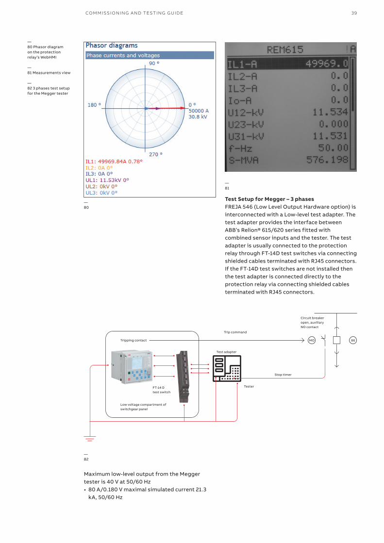
—80 Phasor diagram on the protection relay’s WebHMI
—81 Measurements view
—82 3 phases test setup for the Megger tester
Test Setup for Megger – 3 phasesFREJA 546 (Low Level Output Hardware option) is interconnected with a Low-level test adapter. The test adapter provides the interface between ABB’s Relion® 615/620 series fitted with combined sensor inputs and the tester. The test adapter is usually connected to the protection relay through FT-14D test switches via connecting shielded cables terminated with RJ45 connectors. If the FT-14D test switches are not installed then the test adapter is connected directly to the protection relay via connecting shielded cables terminated with RJ45 connectors.
Maximum low-level output from the Megger tester is 40 V at 50/60 Hz• 80 A/0.180 V maximal simulated current 21.3
kA, 50/60 Hz
—82
Tripping contact
FT-14 D test switch
Circuit breaker open, auxiliary NO contact
Stop timer
Trip command
Test adapter
Tester
86MO
Low voltage compartment of switchgear panel
40 ANSI MEDIUM VOLTAGE METAL-CLAD DIGITAL SWITCHGEAR
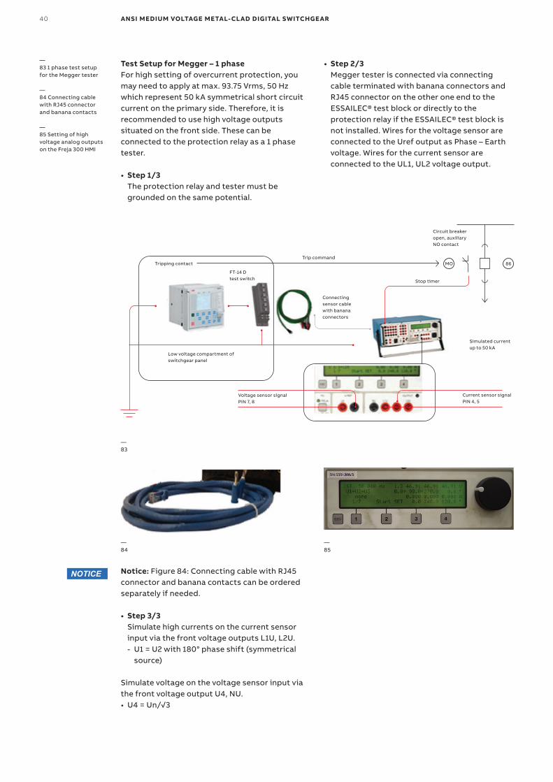
—83 1 phase test setup for the Megger tester
—84 Connecting cable with RJ45 connector and banana contacts
—85 Setting of high voltage analog outputs on the Freja 300 HMI
Test Setup for Megger – 1 phaseFor high setting of overcurrent protection, you may need to apply at max. 93.75 Vrms, 50 Hz which represent 50 kA symmetrical short circuit current on the primary side. Therefore, it is recommended to use high voltage outputs situated on the front side. These can be connected to the protection relay as a 1 phase tester.
• Step 1/3 The protection relay and tester must be grounded on the same potential.
—84
—85
• Step 2/3 Megger tester is connected via connecting cable terminated with banana connectors and RJ45 connector on the other one end to the ESSAILEC® test block or directly to the protection relay if the ESSAILEC® test block is not installed. Wires for the voltage sensor are connected to the Uref output as Phase – Earth voltage. Wires for the current sensor are connected to the UL1, UL2 voltage output.
Notice: Figure 84: Connecting cable with RJ45 connector and banana contacts can be ordered separately if needed.
• Step 3/3 Simulate high currents on the current sensor input via the front voltage outputs L1U, L2U. - U1 = U2 with 180° phase shift (symmetrical
source)
Simulate voltage on the voltage sensor input via the front voltage output U4, NU.• U4 = Un/√3
NOTICE
—83
Circuit breaker open, auxiliary NO contact
Connecting sensor cable with banana connectors
Voltage sensor signal PIN 7, 8
Current sensor signal PIN 4, 5
Simulated current up to 50 kA
86MO
FT-14 D test switch
Low voltage compartment of switchgear panel
Tripping contactTrip command
Stop timer
CO M M ISSI O N I N G A N D TE S TI N G G U I D E 41
—87
—88
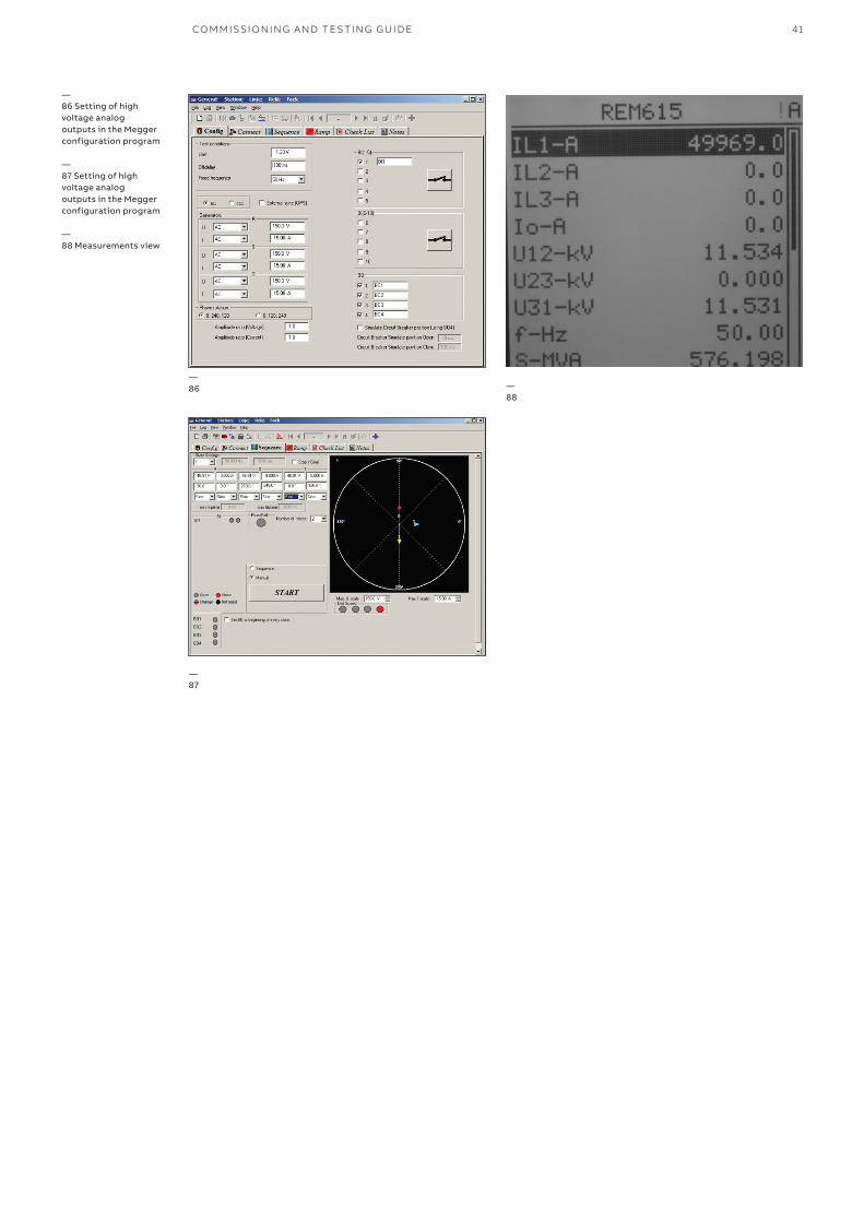
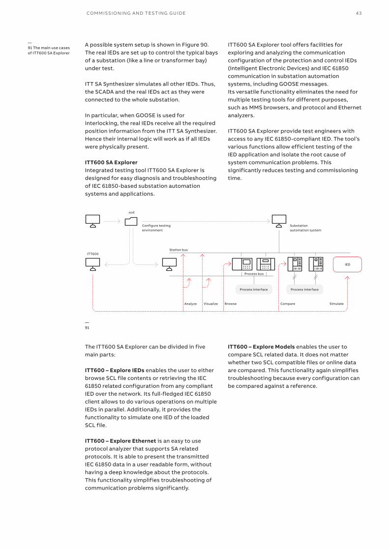
—86 Setting of high voltage analog outputs in the Megger configuration program
—87 Setting of high voltage analog outputs in the Megger configuration program
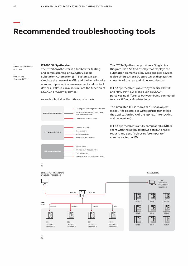
—88 Measurements view
—86
42 ANSI MEDIUM VOLTAGE METAL-CLAD DIGITAL SWITCHGEAR
—90
SCADA system (MicroSCADA) 172.16.100.1 / 255.255.0.0
Simulated IEDs
IED10
IED10
IED10
IED1172.16.1.1255.255.0.0
IED2172.16.2.1255.255.0.0
IED3172.16.3.1255.255.0.0
IED4172.16.4.1255.255.0.0
Port #1 Port #8
Port #2 Port #3 Port #4 Port #5
IED10
IED10
IED10
IED10
IED10
IED10
ITT SA Synthesizer172.16.100.99 255.255.0.0
Real IEDs
—89
—89 ITT SA Synthesizer overview
—90 Real and simulated IEDs
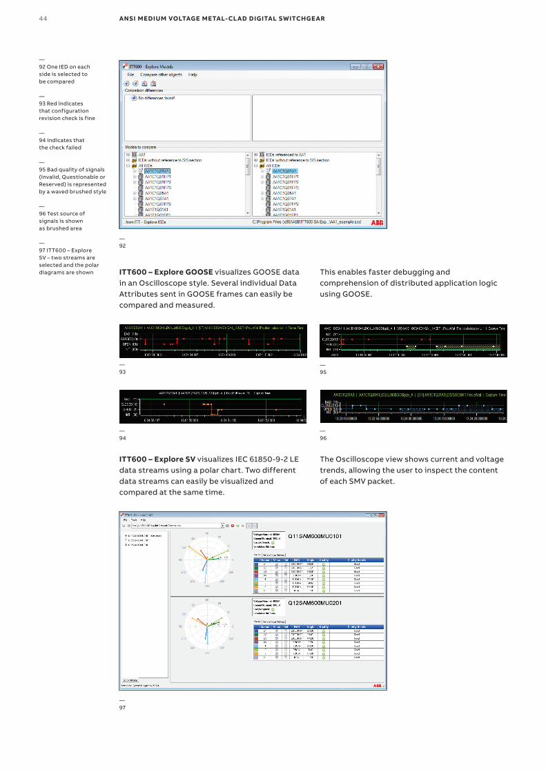
—Recommended troubleshooting tools
ITT600 SA SynthesizerThe ITT SA Synthesizer is a toolbox for testing and commissioning of IEC 61850 based Substation Automation (SA) Systems. It can simulate the network traffic and the behavior of a number of protection, measurement and control devices (IEDs). It can also simulate the function of a SCADA or Gateway device.
As such it is divided into three main parts:
The ITT SA Synthesizer provides a Single Line Diagram like a SCADA display that displays the substation elements, simulated and real devices. It also offers a tree structure which displays the contents of the real and simulated devices.
ITT SA Synthesizer is able to synthesize GOOSE and MMS traffic. A client, such as SCADA, perceives no difference between being connected to a real IED or a simulated one.
The simulated IED is more than just an object model, it is possible to write scripts that mimic the application logic of the IED (e.g. interlocking and reservation).
ITT SA Synthesizer is a fully compliant IEC 61850 client with the ability to browse an IED, enable reports and send “Select-Before-Operate” commands to the IED.
ITT - Synthesize GOOSE
Sending and receiving GOOSE frames
Connect to an IED
Simulate IEDs
Enable reports
Simulate a whole substation
Send commands
Full MMS server
Browse the IED contents
Programmable IED application logic
Updating the Datamodel and Views with received frames
Counters for GOOSE frames
ITT - Synthesize client
ITT - Synthesize IEDs
CO M M ISSI O N I N G A N D TE S TI N G G U I D E 43
A possible system setup is shown in Figure 90. The real IEDs are set up to control the typical bays of a substation (like a line or transformer bay) under test.
ITT SA Synthesizer simulates all other IEDs. Thus, the SCADA and the real IEDs act as they were connected to the whole substation.
In particular, when GOOSE is used for interlocking, the real IEDs receive all the required position information from the ITT SA Synthesizer. Hence their internal logic will work as if all IEDs were physically present.
ITT600 SA ExplorerIntegrated testing tool ITT600 SA Explorer is designed for easy diagnosis and troubleshooting of IEC 61850-based substation automation systems and applications.
ITT600 SA Explorer tool offers facilities for exploring and analyzing the communication configuration of the protection and control IEDs (Intelligent Electronic Devices) and IEC 61850 communication in substation automation systems, including GOOSE messages. Its versatile functionality eliminates the need for multiple testing tools for different purposes, such as MMS browsers, and protocol and Ethernet analyzers.
ITT600 SA Explorer provide test engineers with access to any IEC 61850-compliant IED. The tool’s various functions allow efficient testing of the IED application and isolate the root cause of system communication problems. This significantly reduces testing and commissioning time.
—91
IED
ITT600
Configure testing environment
Substation automation system
.scd
Process interfaceProcess interface
Process bus
Station bus
Analyze Visualize Browse Compare Simulate
—91 The main use cases of ITT600 SA Explorer
The ITT600 SA Explorer can be divided in five main parts:
ITT600 – Explore IEDs enables the user to either browse SCL file contents or retrieving the IEC 61850 related configuration from any compliant IED over the network. Its full-fledged IEC 61850 client allows to do various operations on multiple IEDs in parallel. Additionally, it provides the functionality to simulate one IED of the loaded SCL file.
ITT600 – Explore Ethernet is an easy to use protocol analyzer that supports SA related protocols. It is able to present the transmitted IEC 61850 data in a user readable form, without having a deep knowledge about the protocols. This functionality simplifies troubleshooting of communication problems significantly.
ITT600 – Explore Models enables the user to compare SCL related data. It does not matter whether two SCL compatible files or online data are compared. This functionality again simplifies troubleshooting because every configuration can be compared against a reference.
44 ANSI MEDIUM VOLTAGE METAL-CLAD DIGITAL SWITCHGEAR
ITT600 – Explore GOOSE visualizes GOOSE data in an Oscilloscope style. Several individual Data Attributes sent in GOOSE frames can easily be compared and measured.
ITT600 – Explore SV visualizes IEC 61850-9-2 LE data streams using a polar chart. Two different data streams can easily be visualized and compared at the same time.
—92
—93
—94
—95
—96
This enables faster debugging and comprehension of distributed application logic using GOOSE.
The Oscilloscope view shows current and voltage trends, allowing the user to inspect the content of each SMV packet.
—92 One IED on each side is selected to be compared
—93 Red indicates that configuration revision check is fine
—94 indicates that the check failed
—95 Bad quality of signals (Invalid, Questionable or Reserved) is represented by a waved brushed style
—96 Test source of signals is shown as brushed area
—97 ITT600 – Explore SV – two streams are selected and the polar diagrams are shown
—97
CO M M ISSI O N I N G A N D TE S TI N G G U I D E 45
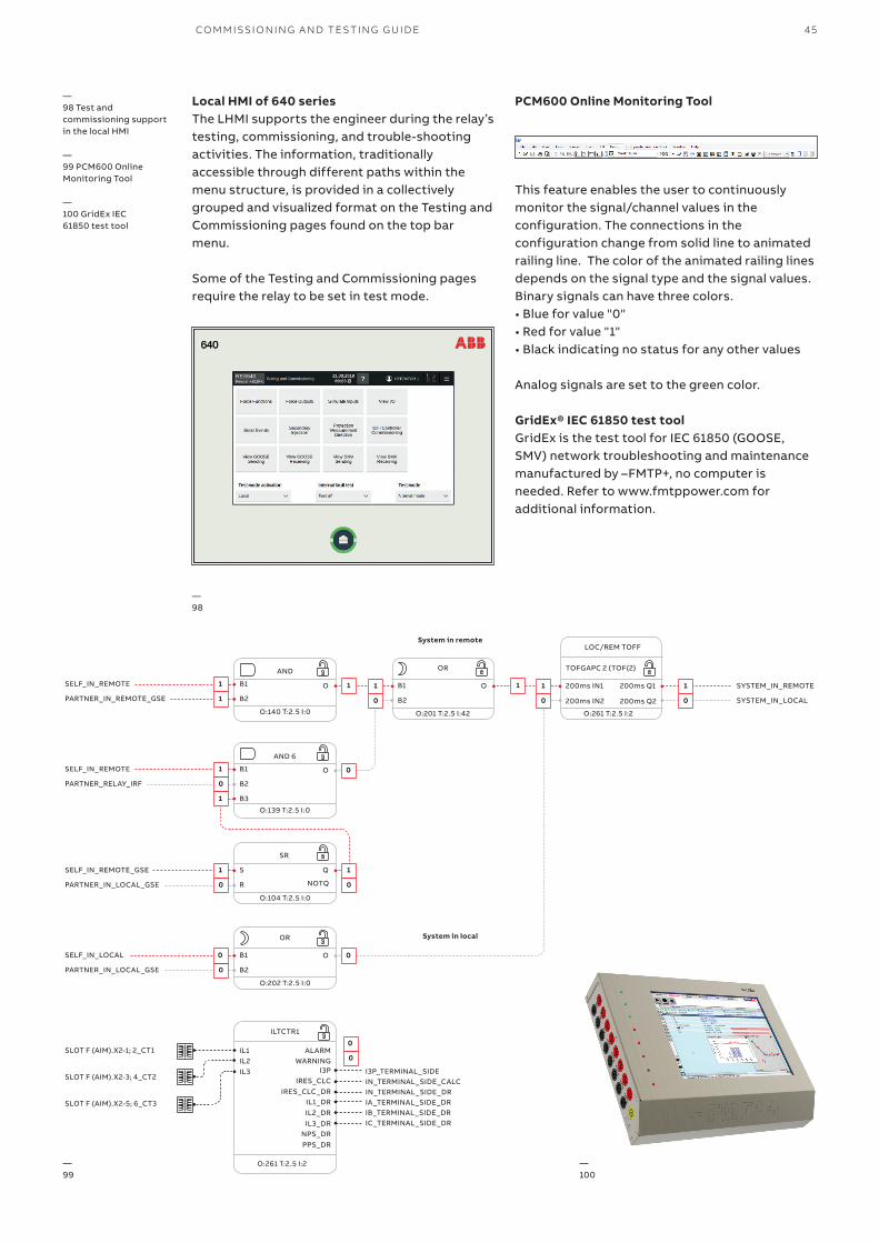
—98 Test and commissioning support in the local HMI
—99 PCM600 Online Monitoring Tool
—100 GridEx IEC 61850 test tool
Local HMI of 640 seriesThe LHMI supports the engineer during the relay’s testing, commissioning, and trouble-shooting activities. The information, traditionally accessible through different paths within the menu structure, is provided in a collectively grouped and visualized format on the Testing and Commissioning pages found on the top bar menu.
Some of the Testing and Commissioning pages require the relay to be set in test mode.
PCM600 Online Monitoring Tool
This feature enables the user to continuously monitor the signal/channel values in the configuration. The connections in the configuration change from solid line to animated railing line. The color of the animated railing lines depends on the signal type and the signal values. Binary signals can have three colors.• Blue for value "0" • Red for value "1" • Black indicating no status for any other values
Analog signals are set to the green color.
—98
GridEx® IEC 61850 test toolGridEx is the test tool for IEC 61850 (GOOSE, SMV) network troubleshooting and maintenance manufactured by –FMTP+, no computer is needed. Refer to www.fmtppower.com for additional information.
—100
—99
System in remote
System in local
SELF_IN_REMOTE
PARTNER_IN_REMOTE_GSE
SYSTEM_IN_REMOTE
SYSTEM_IN_LOCAL
SELF_IN_REMOTE_GSE
PARTNER_IN_LOCAL_GSE
SELF_IN_LOCAL
PARTNER_IN_LOCAL_GSE
SLOT F (AIM).X2-1; 2_CT1
SLOT F (AIM).X2-3; 4_CT2
SLOT F (AIM).X2-5; 6_CT3
I3P_TERMINAL_SIDEIN_TERMINAL_SIDE_CALCIN_TERMINAL_SIDE_DRIA_TERMINAL_SIDE_DRIB_TERMINAL_SIDE_DRIC_TERMINAL_SIDE_DR
SELF_IN_REMOTE
PARTNER_RELAY_IRF
1
1 1
1 1 11 1
0
00
0
1
B1
S Q
O
O
O
NOTQ
B1
B1
AND
SR
OR
AND 6
O:140 T:2.5 I:0
O:104 T:2.5 I:0
O:202 T:2.5 I:0
O:139 T:2.5 I:0
1
0 0
0 0 0
0
0
0
1
B2
R
B2
B2
B3
OB1
OR TOFGAPC 2 (TOF(2)
LOC/REM TOFF
ILTCTR1
200ms IN1
IL1 ALARM
IRES_CLC_DR
IL3_DR
200ms Q1
200ms Q2200ms IN2
IL2 WARNINGI3P
IL1_DR
NPS_DR
IL3IRES_CLC
IL2_DR
PPS_DR
O:201 T:2.5 I:42 O:261 T:2.5 I:2
O:261 T:2.5 I:2
B2

46 ANSI MEDIUM VOLTAGE METAL-CLAD DIGITAL SWITCHGEAR
—Glossary
615 series Relion® 615 series protection and control relays
620 series Relion® 620 series protection and control relays
640 series Relion® 640 series protection and control relays
ACT Application Configuration Tool
ANSI American National Standards Institute
AFS Family ABB FOX Switch family for utility applications
BB Busbar
CB Circuit Breaker
CBFP Circuit Breaker Failure protection
CT Current Transformer
Ethernet A standard for connecting a family of frame-based computer networking technologies into a LAN
GOOSE Generic Object-Oriented Substation Event
HMI Human Machine Interface
HSR High Availability Seamless Redundancy
ID Identifier
IEC International Electrotechnical Commission
IEC 61850 International standard for communication networks and systems for power utility automation
IEC 61850-8-1 Station bus (MMS + GOOSE)
IEC 61850-9-2 Process bus
IED Intelligent Electronic Device
IEEEInstitute of Electrical and Electronics Engineers. The IEEE standard groups defined the PTP
and Power profile
IEEE 1588 Standard for Precision Clock Synchronization Proto-col for Networked Measurement and Control Systems
IP Internet Protocol
ITTIntegrated Testing Toolbox for efficient testing and commissioning of IEC 61850 based Substation
Automation Systems
I/O Input / Output
LAN Local area network
LBBP Logic Busbar protection
LE Light Edition (Lite Edition)
LED Light Emitting Diode
LHMI Local Human Machine Interface
L1U Voltage in phase 1
L2U Voltage in phase 2
MMS Manufacturing Message Specification
MV Medium voltage
PC Personal computer
PCM600 Protection and control relay Manager
PRP Parallel Redundancy Protocol
PTPv2 Precision Time Protocol Version 2
RJ45 Galvanic connector type
RMS Root mean square
SA Substation Automation
SCADA Supervisory Control and Data Acquisition
SCL XML-based substation description configuration language defined by IEC 61850
SMV Sampled Measured Value
SNMP Simple Network Management Protocol
SV Sampled Value
SW Software
TC Transparent clock
U-REF Amplitude of the voltage reference generator
VLAN Virtual LAN
VT Voltage Transformer


1VA
L10
84
02-
TG
Rev
A D
ecem
ber
20
21
—ABB Inc.305 Gregson DriveCary, NC 27511 USAabb.com/contacts
abb.com/mediumvoltage
The information contained in this document is for generalinformation purposes only. While ABB strives to keep theinformation up to date and correct, it makes norepresentations or warranties of any kind, express orimplied, about the completeness, accuracy, reliability,suitability or availability with respect to the information,products, services, or related graphics contained in thedocument for any purpose. Any reliance placed on suchinformation is therefore strictly at your own risk. ABBreserves the right to discontinue any product or serviceat any time.
© Copyright 2021 ABB. All rights reserved.
Related Documents


![[ ANSI C37.20 and NEMA SG-5 ]€¦ · ANSI C37.20 and NEMA SG-5 04 Description and Application The HMS Vacuum Medium Voltage Metal-clad Switchgear is an integrated set of drawout](https://static.cupdf.com/doc/110x72/60b1aa739f7bfd38ee6b2815/-ansi-c3720-and-nema-sg-5-ansi-c3720-and-nema-sg-5-04-description-and-application.jpg)