— LOW VOLTAGE AC DRIVES ABB industrial drives ACS880, single drives 0.55 to 6000 kW

Welcome message from author
This document is posted to help you gain knowledge. Please leave a comment to let me know what you think about it! Share it to your friends and learn new things together.
Transcript

—LOW VOLTAGE AC DRIVES
ABB industrial drivesACS880, single drives0.55 to 6000 kW

— Uncompromised productivity. ACS880 series.

—ABB industrial drivesACS880 single drives
AACS880 DRIVE SERIES004 – 021
EWALL-MOUNTED DRIVES028 – 031
BEU ECODESIGN REGULATION025
FCABINET-BUILT DRIVES032 – 035
CTECHNICAL DATA026
G
REGENERATIVE DRIVES036 – 041
ILIQUID-COOLED DRIVES048 – 054
D
HOW TO SELECT A DRIVE027
H
ULTRA-LOW HARMONIC DRIVES042 – 047
JDIMENSIONS055 – 057
K
STANDARD INTERFACE AND EXTENSIONS058 – 059
LOPTIONS060 – 091
MABB AUTOMATION PRODUCTS93
N
MOTORS094 – 095
004 – 021 THE ALL-COMPATIBLE ACS880 DRIVE SERIES 006 – 007 SIMPLIFY YOUR WORLD WITHOUT LIMITING YOUR POSSIBILITIES 008 – 009 COMPLETE ACS880 SINGLE DRIVES OFFERING FOR A WIDE RANGE OF INDUSTRIAL APPLICATIONS 010 EASY TO USE 011 SIMPLE TO SELECT AND INSTALL 012 VIRTUAL COMMISSIONING 013 ABB ACCESS 014 COMPREHENSIVE CONNECTIVITY 015 MINIMIZED DOWNTIME 016 SMARTER SOLUTIONS WITH DRIVE-BASED FUNCTIONAL SAFETY 017 GLOBAL COMPATIBILITY WITH VARIOUS DEMANDS 018 PREMIUM CONTROL AND PROGRAMMABILITY
019 HIGH SPEED COMPRESSORS AND BLOWERS 020 – 021 APPLICATION- AND INDUSTRY-SPECIFIC SOLUTIONS
022 – 023 HIGHER ENCLOSURE CLASS AND FLANGE-MOUNTED DRIVES FOR INSTALLATIONS IN HARSH CONDITIONS 025 EU ECODESIGN REGULATION
026 TECHNICAL DATA
027 HOW TO SELECT A DRIVE 028 – 031 WALL-MOUNTED DRIVES, ACS880-01 032 – 035 CABINET-BUILT DRIVES, ACS880-07 036 – 041 REGENERATIVE DRIVES, ACS880-11, ACS880-17 042 – 047 ULTRA-LOW HARMONIC DRIVES, ACS880-31, ACS880-37 048 – 054 LIQUID-COOLED DRIVES, ACS880-07LC, ACS880-07CLC, ACS880-17LC, ACS880-37LC 055 – 057 DIMENSIONS 058 – 059 STANDARD INTERFACE AND EXTENSIONS FOR PLUG-IN CONNECTIVITY 060 – 091 OPTIONS
060 CONTROL PANEL OPTIONS 061 DOOR MOUNTING AND PANEL BUS 062 COMMUNICATION AND CONNECTIVITY 063 CONNECTIVITY TO AUTOMATION SYSTEMS 064 PROFINET S2 SYSTEM REDUNDANCY FOR ABB DRIVES 065 FEEDBACK INTERFACE AND DDCS COMMUNICATION OPTIONS 066 – 067 ABB ABILITY™ CONDITION MONITORING FOR DRIVES 068 – 069 COMMISSIONING, PROGRAMMING AND CUSTOMIZATION TOOLS 070 – 071 SAFETY OPTIONS 072 – 073 EMC – ELECTROMAGNETIC COMPATIBILITY 074 – 075 FOR EXPLOSIVE ATMOSPHERES 076 – 081 SINE FILTERS 082 – 089 BRAKE OPTIONS 090 – 091 DU/DT FILTERS
093 ABB AUTOMATION PRODUCTS 094 – 095 CHOOSE THE RIGHT MOTOR FOR YOUR APPLICATION 096 – 097 OUR SERVICE EXPERTISE, YOUR ADVANTAGE
098 DRIVETUNE MOBILE APPLICATION FOR WIRELESS ACCESS
099 ABB SMARTGUIDE – ACS880-01 100 – 107 SUMMARY OF FEATURES AND OPTIONS
ABB MOTION SERVICES096 – 097
OR
SUMMARY OF FEATURES AND OPTIONS100 – 107
ABB SMARTGUIDE – ACS880-01099 Q
DRIVETUNE MOBILE APPLICATION FOR WIRELESS ACCESS098
P
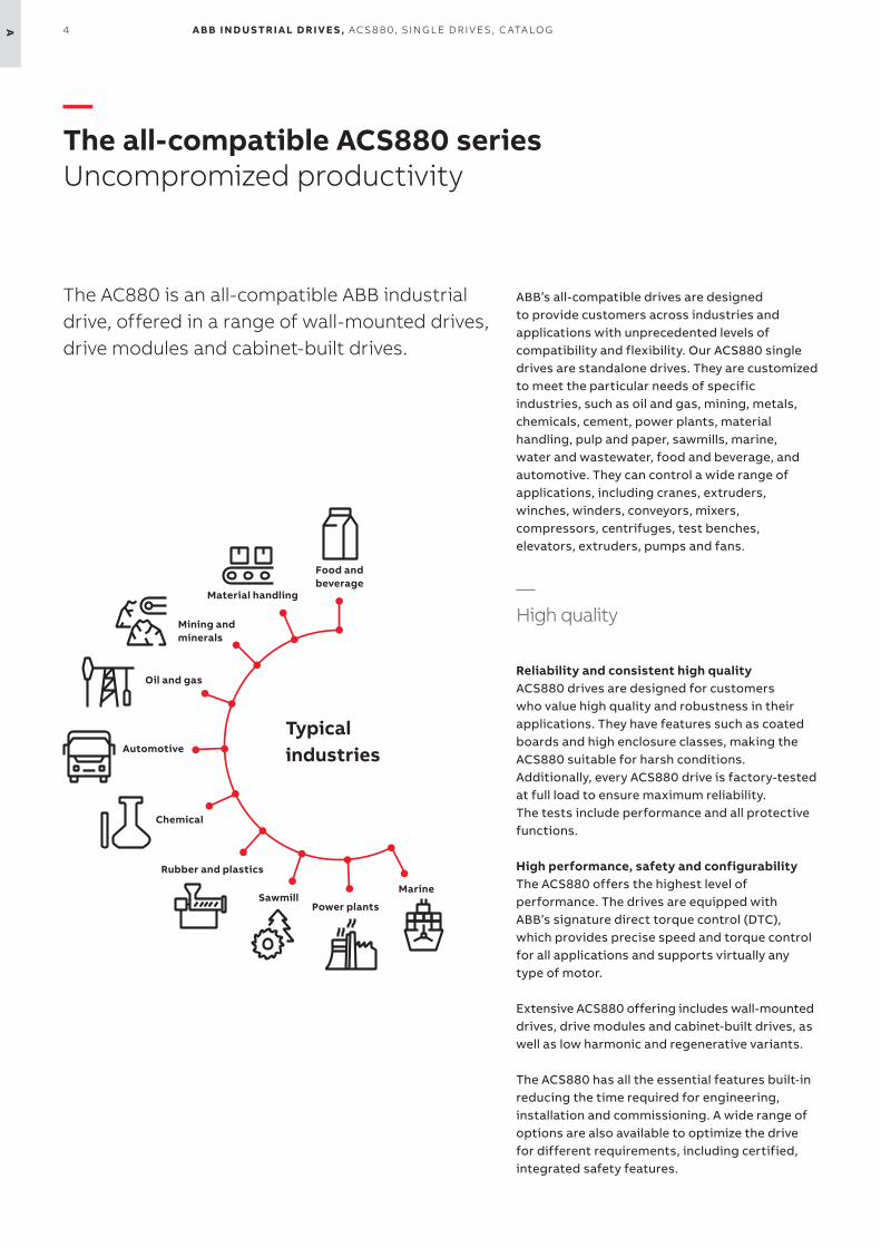
Typical industries
Food and beverage
Material handling
Mining and minerals
Oil and gas
Marine
Power plantsSawmill
Automotive
Rubber and plastics
Chemical
4 A B B I N D U S TR I A L D R I V E S , AC S 8 8 0, S I N G L E D R I V E S , C ATA LO GA
ABB’s all-compatible drives are designed to provide customers across industries and applications with unprecedented levels of compatibility and flexibility. Our ACS880 single drives are standalone drives. They are customized to meet the particular needs of specific industries, such as oil and gas, mining, metals, chemicals, cement, power plants, material handling, pulp and paper, sawmills, marine, water and wastewater, food and beverage, and automotive. They can control a wide range of applications, including cranes, extruders, winches, winders, conveyors, mixers, compressors, centrifuges, test benches, elevators, extruders, pumps and fans.
—High quality
Reliability and consistent high qualityACS880 drives are designed for customers who value high quality and robustness in their applications. They have features such as coated boards and high enclosure classes, making the ACS880 suitable for harsh conditions. Additionally, every ACS880 drive is factory-tested at full load to ensure maximum reliability. The tests include performance and all protective functions.
High performance, safety and configurabilityThe ACS880 offers the highest level of performance. The drives are equipped with ABB’s signature direct torque control (DTC), which provides precise speed and torque control for all applications and supports virtually any type of motor.
Extensive ACS880 offering includes wall-mounted drives, drive modules and cabinet-built drives, as well as low harmonic and regenerative variants.
The ACS880 has all the essential features built-in reducing the time required for engineering, installation and commissioning. A wide range of options are also available to optimize the drive for different requirements, including certified, integrated safety features.
—The all-compatible ACS880 seriesUncompromized productivity
The AC880 is an all-compatible ABB industrial drive, offered in a range of wall-mounted drives, drive modules and cabinet-built drives.

5 ATH E A L L- CO M PATI B L E AC S 8 8 0 SER I E S
6 A B B I N D U S TR I A L D R I V E S , AC S 8 8 0, S I N G L E D R I V E S , C ATA LO GA
—Simplify your world without limiting your possibilities
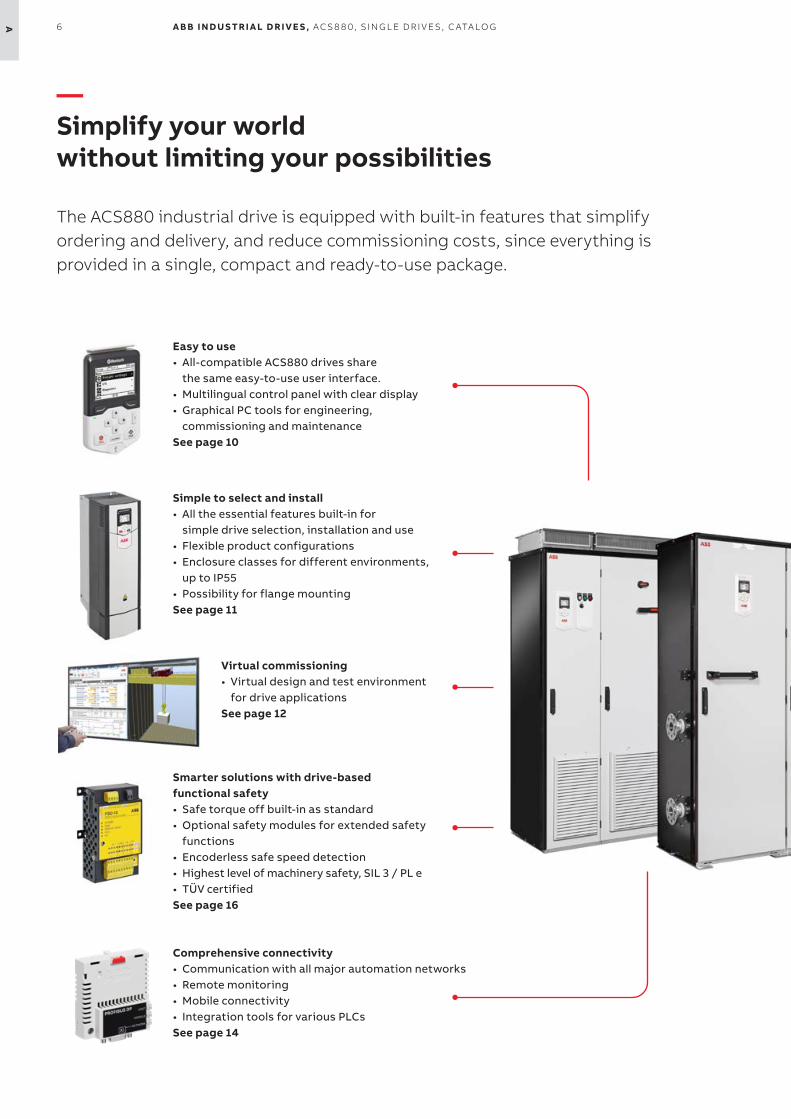
The ACS880 industrial drive is equipped with built-in features that simplify ordering and delivery, and reduce commissioning costs, since everything isprovided in a single, compact and ready-to-use package.
Easy to use• All-compatible ACS880 drives share
the same easy-to-use user interface.• Multilingual control panel with clear display• Graphical PC tools for engineering,
commissioning and maintenanceSee page 10
Simple to select and install• All the essential features built-in for
simple drive selection, installation and use• Flexible product configurations• Enclosure classes for different environments,
up to IP55• Possibility for flange mounting See page 11
Comprehensive connectivity• Communication with all major automation networks • Remote monitoring • Mobile connectivity• Integration tools for various PLCsSee page 14
Smarter solutions with drive-based functional safety• Safe torque off built-in as standard• Optional safety modules for extended safety
functions• Encoderless safe speed detection• Highest level of machinery safety, SIL 3 / PL e• TÜV certifiedSee page 16
Virtual commissioning• Virtual design and test environment
for drive applicationsSee page 12

77TH E A L L- CO M PATI B L E AC S 8 8 0 SER I E S A
—Nine-year maintenance interval
Minimized downtime• Robust, long lifetime design for maximum
reliability• Coated circuit boards for harsh conditions• Removable memory unit for fast drive
replacement • Each drive factory-tested at full load• Nine-year maintenance interval• Worldwide service and support• Advanced features for analyzing and
resolving issuesSee page 15
Global compatibility with various demands• Global product approvals, e.g. CE, UL, cUL, CSA,
marine certifications, ATEX• Support for various motor types• Low harmonic content• Possibility for regenerationSee page 17
Application- and industry-specific solutions• Ready-made optimized solutions for various
applications and industriesSee page 20
Premium control and programmability• Direct torque control (DTC) for precise control• Speed, torque and position control as well as
synchronizing• Adaptive programming as standard• Drive-based PLC programmability (IEC 61131-3)
for fully customized solutionsSee page 18
8 A B B I N D U S TR I A L D R I V E S , AC S 8 8 0, S I N G L E D R I V E S , C ATA LO GA
—Complete ACS880 single drives offering for a wide range of industrial applications
ACS880 drives are designed for customers who value high quality and robustness. They offer the highest level of performance for a wide range of industrial applications.
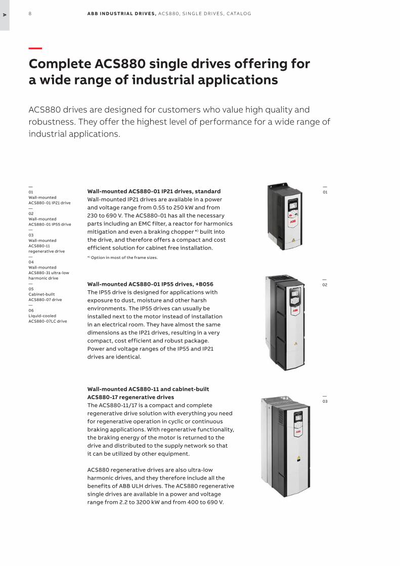
Wall-mounted ACS880-01 IP21 drives, standardWall-mounted IP21 drives are available in a power and voltage range from 0.55 to 250 kW and from 230 to 690 V. The ACS880-01 has all the necessary parts including an EMC filter, a reactor for harmonics mitigation and even a braking chopper *) built into the drive, and therefore offers a compact and cost efficient solution for cabinet free installation.
*) Option in most of the frame sizes.
Wall-mounted ACS880-01 IP55 drives, +B056The IP55 drive is designed for applications with exposure to dust, moisture and other harsh environments. The IP55 drives can usually be installed next to the motor instead of installation in an electrical room. They have almost the same dimensions as the IP21 drives, resulting in a very compact, cost efficient and robust package. Power and voltage ranges of the IP55 and IP21 drives are identical.
Wall-mounted ACS880-11 and cabinet-built ACS880-17 regenerative drivesThe ACS880-11/17 is a compact and complete regenerative drive solution with everything you need for regenerative operation in cyclic or continuous braking applications. With regenerative functionality, the braking energy of the motor is returned to the drive and distributed to the supply network so that it can be utilized by other equipment.
ACS880 regenerative drives are also ultra-low harmonic drives, and they therefore include all the benefits of ABB ULH drives. The ACS880 regenerative single drives are available in a power and voltage range from 2.2 to 3200 kW and from 400 to 690 V.
—01
—02
—01 Wall-mounted ACS880-01 IP21 drive— 02 Wall-mounted ACS880-01 IP55 drive — 03 Wall-mounted ACS880-11 regenerative drive—04 Wall-mounted ACS880-31 ultra-low harmonic drive— 05 Cabinet-built ACS880-07 drive— 06 Liquid-cooled ACS880-07LC drive
—03
9TH E A L L- CO M PATI B L E AC S 8 8 0 SER I E S A
—05
—06
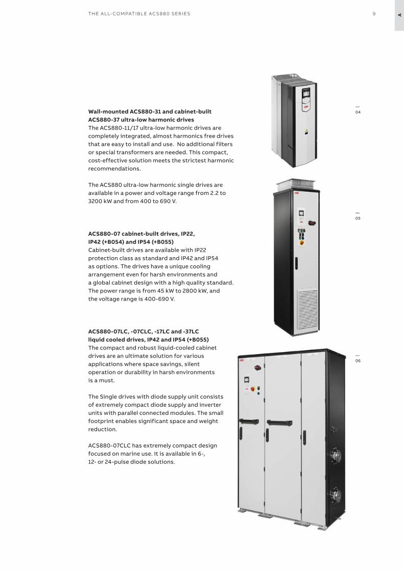
—04Wall-mounted ACS880-31 and cabinet-built
ACS880-37 ultra-low harmonic drivesThe ACS880-11/17 ultra-low harmonic drives are completely integrated, almost harmonics free drives that are easy to install and use. No additional filters or special transformers are needed. This compact, cost-effective solution meets the strictest harmonic recommendations.
The ACS880 ultra-low harmonic single drives are available in a power and voltage range from 2.2 to 3200 kW and from 400 to 690 V.
ACS880-07 cabinet-built drives, IP22, IP42 (+B054) and IP54 (+B055)Cabinet-built drives are available with IP22 protection class as standard and IP42 and IP54 as options. The drives have a unique cooling arrangement even for harsh environments and a global cabinet design with a high quality standard. The power range is from 45 kW to 2800 kW, and the voltage range is 400-690 V.
ACS880-07LC, -07CLC, -17LC and -37LC liquid cooled drives, IP42 and IP54 (+B055)The compact and robust liquid-cooled cabinet drives are an ultimate solution for various applications where space savings, silent operation or durability in harsh environments is a must.
The Single drives with diode supply unit consists of extremely compact diode supply and inverter units with parallel connected modules. The small footprint enables significant space and weightreduction.
ACS880-07CLC has extremely compact design focused on marine use. It is available in 6-, 12- or 24-pulse diode solutions.
10 A B B I N D U S TR I A L D R I V E S , AC S 8 8 0, S I N G L E D R I V E S , C ATA LO GA
—Easy to use
All-compatible user interface saves commissioning and learning timeThe ACS880 is part of ABB’s all-compatible drives portfolio. Other drives in this portfolio are the ACS380, ACS480 and ACS580.
These drives share the same easy-to-use PC tools and multilingual control panels. To further enhance the user experience, they also have the same parameter structure, which saves time on commissioning and learning.
The drives also share the same communication options, simplifying the use of drives and spare parts handling.
—The ACS880, part of the all-compatible drives portfolio
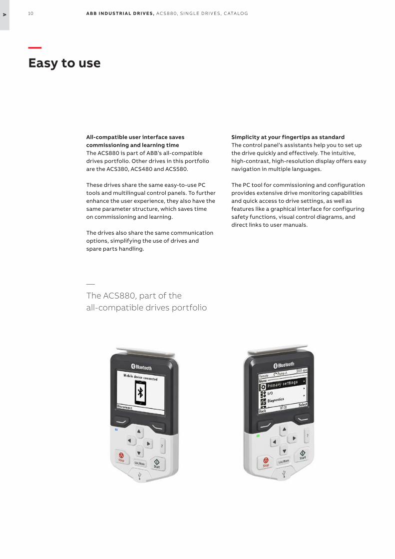
Simplicity at your fingertips as standardThe control panel’s assistants help you to set up the drive quickly and effectively. The intuitive, high-contrast, high-resolution display offers easy navigation in multiple languages.
The PC tool for commissioning and configuration provides extensive drive monitoring capabilities and quick access to drive settings, as well as features like a graphical interface for configuring safety functions, visual control diagrams, and direct links to user manuals.
Choke
Safety functions
Modbus RTU interface
EMC filter
Extensive I/O
Up to IP55 enclosure classBrake chopper
Direct torque control
11TH E A L L- CO M PATI B L E AC S 8 8 0 SER I E S A
—Simple to select and install
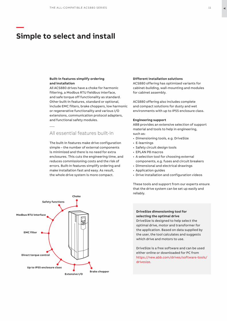
Built-in features simplify ordering and installationAll ACS880 drives have a choke for harmonic filtering, a Modbus RTU fieldbus interface, and safe torque off functionality as standard. Other built-in features, standard or optional, include EMC filters, brake choppers, low harmonic or regenerative functionality and various I/O extensions, communication protocol adapters, and functional safety modules.
—All essential features built-in
The built-in features make drive configuration simple – the number of external components is minimized and there is no need for extra enclosures. This cuts the engineering time, and reduces commissioning costs and the risk of errors. Built-in features simplify ordering and make installation fast and easy. As result, the whole drive system is more compact.
Different installation solutionsACS880 offering has optimized variants for cabinet-building, wall-mounting and modules for cabinet assembly.
ACS880 offering also includes complete and compact solutions for dusty and wet environments with up to IP55 enclosure class.
Engineering supportABB provides an extensive selection of support material and tools to help in engineering, such as:• Dimensioning tools, e.g. DriveSize• E-learnings• Safety circuit design tools• EPLAN P8 macros• A selection tool for choosing external
components, e.g. fuses and circuit breakers• Dimensional and electrical drawings• Application guides• Drive installation and configuration videos
These tools and support from our experts ensure that the drive system can be set up easily and reliably.
DriveSize dimensioning tool for selecting the optimal driveDriveSize is designed to help select the optimal drive, motor and transformer for the application. Based on data supplied by the user, the tool calculates and suggests which drive and motors to use. DriveSize is a free software and can be used either online or downloaded for PC from https://new.abb.com/drives/software-tools/drivesize.
—Virtual commissioning
Virtual engineering and commissioning allow machine builders and system integrators to develop and simulate entire industrial processing lines and machines, including ABB drives, without actually running the hardware. This gives valuable benefits in the phases of designing, commissioning and operating machines.
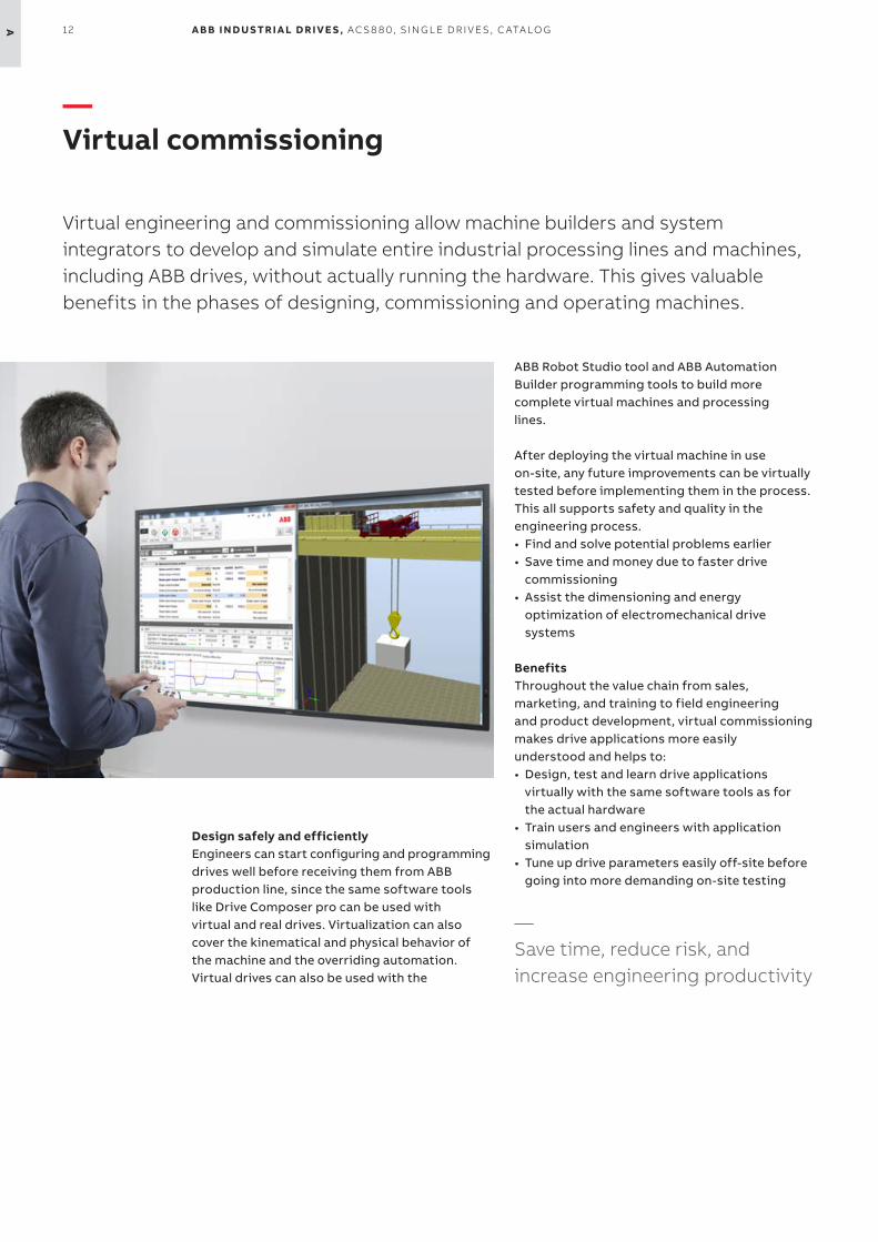
Design safely and efficientlyEngineers can start configuring and programming drives well before receiving them from ABB production line, since the same software tools like Drive Composer pro can be used with virtual and real drives. Virtualization can also cover the kinematical and physical behavior of the machine and the overriding automation. Virtual drives can also be used with the
ABB Robot Studio tool and ABB Automation Builder programming tools to build more complete virtual machines and processing lines.
After deploying the virtual machine in use on-site, any future improvements can be virtually tested before implementing them in the process. This all supports safety and quality in the engineering process.• Find and solve potential problems earlier• Save time and money due to faster drive
commissioning• Assist the dimensioning and energy
optimization of electromechanical drive systems
BenefitsThroughout the value chain from sales, marketing, and training to field engineering and product development, virtual commissioning makes drive applications more easily understood and helps to:• Design, test and learn drive applications
virtually with the same software tools as for the actual hardware
• Train users and engineers with application simulation
• Tune up drive parameters easily off-site before going into more demanding on-site testing
—Save time, reduce risk, and increase engineering productivity
12 A B B I N D U S TR I A L D R I V E S , AC S 8 8 0, S I N G L E D R I V E S , C ATA LO GA
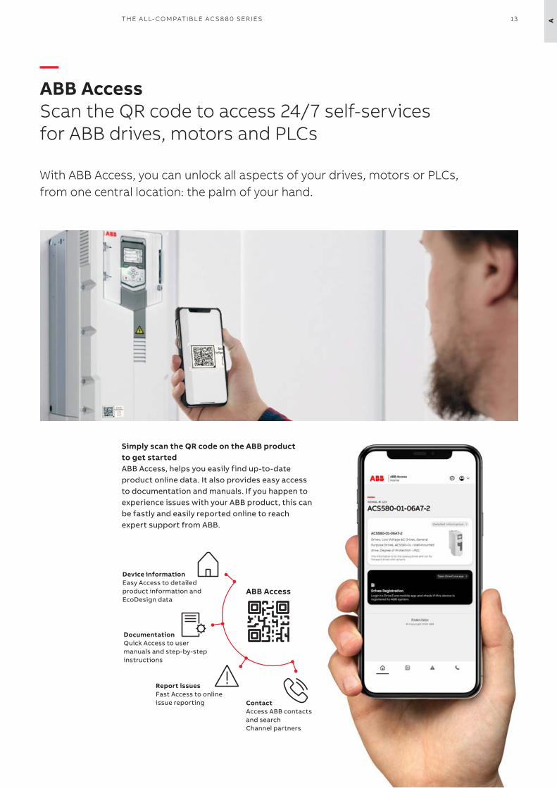
—ABB AccessScan the QR code to access 24/7 self-services for ABB drives, motors and PLCs
With ABB Access, you can unlock all aspects of your drives, motors or PLCs, from one central location: the palm of your hand.
Simply scan the QR code on the ABB product to get startedABB Access, helps you easily find up-to-date product online data. It also provides easy access to documentation and manuals. If you happen to experience issues with your ABB product, this can be fastly and easily reported online to reach expert support from ABB.
Device informationEasy Access to detailed product information and EcoDesign data
ABB Access
DocumentationQuick Access to user manuals and step-by-step instructions
Report issuesFast Access to online issue reporting Contact
Access ABB contacts and search Channel partners
13TH E A L L- CO M PATI B L E AC S 8 8 0 SER I E S A
14 A B B I N D U S TR I A L D R I V E S , AC S 8 8 0, S I N G L E D R I V E S , C ATA LO GA
—Comprehensive connectivity
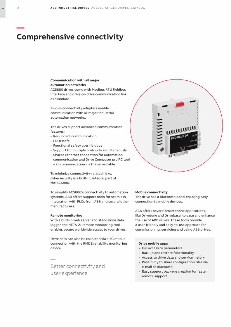
Communication with all majorautomation networksACS880 drives come with Modbus RTU fieldbus interface and drive-to-drive communication link as standard.
Plug-in connectivity adapters enable communication with all major industrial automation networks.
The drives support advanced communication features:• Redundant communication• PROFIsafe• Functional safety over fieldbus• Support for multiple protocols simultaneously• Shared Ethernet connection for automation
communication and Drive Composer pro PC tool – all communication via the same cable
To minimize connectivity-related risks, cybersecurity is a built-in, integral part of the ACS880.
To simplify ACS880ʼs connectivity to automation systems, ABB offers support tools for seamless integration with PLCs from ABB and several other manufacturers.
Remote monitoringWith a built-in web server and standalone data logger, the NETA-21 remote monitoring tool enables secure worldwide access to your drives.
Drive data can also be collected via a 3G mobile connection with the RMDE reliability monitoring device.
—Better connectivity and user experience
Mobile connectivityThe drive has a Bluetooth panel enabling easy connection to mobile devices.
ABB offers several smartphone applications, like Drivetune and Drivebase, to ease and enhance the use of ABB drives. These tools provide a user-friendly and easy-to-use approach for commissioning, servicing and using ABB drives.
Drive mobile apps• Full access to parameters• Backup and restore functionality• Access to drive data and service history• Possibility to share configuration files via
e-mail or Bluetooth• Easy support package creation for faster
remote support
15TH E A L L- CO M PATI B L E AC S 8 8 0 SER I E S A
—Minimized downtime
Accurate and reliable diagnostic information is available for warning and fault messages. Helptexts give detailed information about the warningor fault. Data loggers store critical values before and during an event, such as a fault. The real-time clock allows you to see the exact times of events.
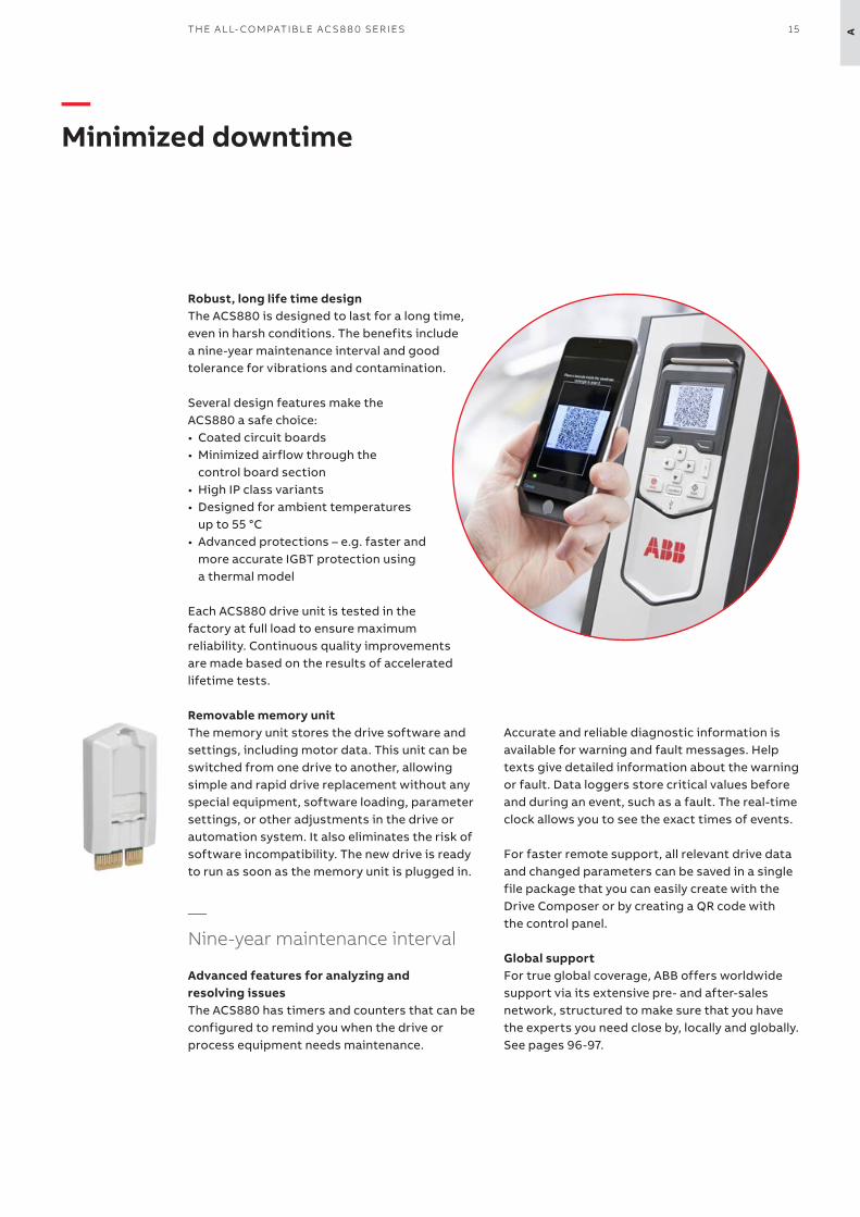
For faster remote support, all relevant drive data and changed parameters can be saved in a single file package that you can easily create with the Drive Composer or by creating a QR code with the control panel.
Global supportFor true global coverage, ABB offers worldwidesupport via its extensive pre- and after-salesnetwork, structured to make sure that you havethe experts you need close by, locally and globally.See pages 96-97.
Robust, long life time designThe ACS880 is designed to last for a long time, even in harsh conditions. The benefits include a nine-year maintenance interval and good tolerance for vibrations and contamination.
Several design features make the ACS880 a safe choice:• Coated circuit boards• Minimized airflow through the
control board section• High IP class variants• Designed for ambient temperatures
up to 55 °C• Advanced protections – e.g. faster and
more accurate IGBT protection using a thermal model
Each ACS880 drive unit is tested in the factory at full load to ensure maximum reliability. Continuous quality improvements are made based on the results of accelerated lifetime tests.
Removable memory unitThe memory unit stores the drive software and settings, including motor data. This unit can be switched from one drive to another, allowing simple and rapid drive replacement without any special equipment, software loading, parameter settings, or other adjustments in the drive or automation system. It also eliminates the risk of software incompatibility. The new drive is ready to run as soon as the memory unit is plugged in.
—Nine-year maintenance interval
Advanced features for analyzing and resolving issuesThe ACS880 has timers and counters that can be configured to remind you when the drive or process equipment needs maintenance.
—Smarter solutions with drive-based functional safety
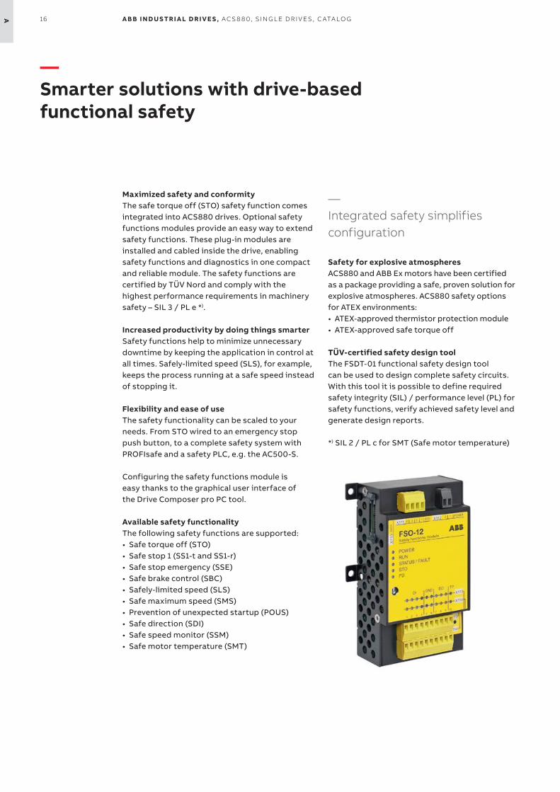
Maximized safety and conformityThe safe torque off (STO) safety function comes integrated into ACS880 drives. Optional safety functions modules provide an easy way to extend safety functions. These plug-in modules are installed and cabled inside the drive, enabling safety functions and diagnostics in one compact and reliable module. The safety functions are certified by TÜV Nord and comply with the highest performance requirements in machinery safety – SIL 3 / PL e *).
Increased productivity by doing things smarterSafety functions help to minimize unnecessary downtime by keeping the application in control at all times. Safely-limited speed (SLS), for example, keeps the process running at a safe speed instead of stopping it.
Flexibility and ease of useThe safety functionality can be scaled to your needs. From STO wired to an emergency stop push button, to a complete safety system with PROFIsafe and a safety PLC, e.g. the AC500-S.
Configuring the safety functions module is easy thanks to the graphical user interface of the Drive Composer pro PC tool.
Available safety functionalityThe following safety functions are supported:• Safe torque off (STO)• Safe stop 1 (SS1-t and SS1-r) • Safe stop emergency (SSE)• Safe brake control (SBC)• Safely-limited speed (SLS)• Safe maximum speed (SMS)• Prevention of unexpected startup (POUS) • Safe direction (SDI)• Safe speed monitor (SSM)• Safe motor temperature (SMT)
—Integrated safety simplifies configuration
Safety for explosive atmospheresACS880 and ABB Ex motors have been certified as a package providing a safe, proven solution for explosive atmospheres. ACS880 safety options for ATEX environments: • ATEX-approved thermistor protection module• ATEX-approved safe torque off
TÜV-certified safety design toolThe FSDT-01 functional safety design tool can be used to design complete safety circuits. With this tool it is possible to define required safety integrity (SIL) / performance level (PL) for safety functions, verify achieved safety level and generate design reports.
*) SIL 2 / PL c for SMT (Safe motor temperature)
16 A B B I N D U S TR I A L D R I V E S , AC S 8 8 0, S I N G L E D R I V E S , C ATA LO GA

—Global compatibility with various demands
Global product approvalsThe ACS880 is a global product and has all the major global approvals, such as CE, UL, cUL, EAC, RCM and TÜV. Industry-specific approval, like different kinds of marine approval, ATEX and SEMI F47 are available either as standard or as an option.
Support for different motor typesThe ACS880 provides reliable control for various motors, such as squirrel cage, high-torque or servo-type permanent magnet, synchronous reluctance (SynRM), submersible and high-speed motors. Practically any encoder type is supported.
Regardless of the motor type, drive commissioning is easy, with no need for laborious manual tuning.
Low harmonic contentAll ACS880 drives have a choke for harmonic reduction. If lower harmonic content is needed, an ultra-low harmonic variant is available.It produces exceptionally low harmonic content and meets the requirements of harmonics recommendations like IEEE519, IEC61000-3-12 and G5/4.
Regeneration of energyThe ACS880 offers a number of solutions for applications where electrical braking is needed. As standard, ACS880 drives have a flux braking feature that provides greater deceleration by increasing the motor flux. If this is not sufficient, the internal brake chopper can be used together with a brake resistor.
The most advanced solution is the ACS880 regenerative drive variant, which allows, continuous braking, providing the possibility for remarkable energy savings.
ACS880 also supports common DC bus configurations, where the braking energy from one load can be utilized by other loads.
17TH E A L L- CO M PATI B L E AC S 8 8 0 SER I E S A
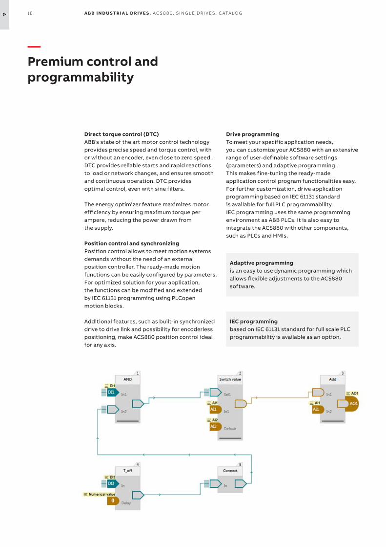
—Premium control and programmability
Direct torque control (DTC)ABBʼs state of the art motor control technology provides precise speed and torque control, with or without an encoder, even close to zero speed. DTC provides reliable starts and rapid reactions to load or network changes, and ensures smooth and continuous operation. DTC provides optimal control, even with sine filters.
The energy optimizer feature maximizes motor efficiency by ensuring maximum torque per ampere, reducing the power drawn from the supply.
Position control and synchronizingPosition control allows to meet motion systems demands without the need of an external position controller. The ready-made motion functions can be easily configured by parameters. For optimized solution for your application, the functions can be modified and extended by IEC 61131 programming using PLCopen motion blocks.
Additional features, such as built-in synchronized drive to drive link and possibility for encoderless positioning, make ACS880 position control ideal for any axis.
Drive programmingTo meet your specific application needs, you can customize your ACS880 with an extensive range of user-definable software settings (parameters) and adaptive programming. This makes fine-tuning the ready-made application control program functionalities easy. For further customization, drive application programming based on IEC 61131 standard is available for full PLC programmability. IEC programming uses the same programming environment as ABB PLCs. It is also easy to integrate the ACS880 with other components, such as PLCs and HMIs.
Adaptive programming is an easy to use dynamic programming which allows flexible adjustments to the ACS880 software.
IEC programming based on IEC 61131 standard for full scale PLC programmability is available as an option.
18 A B B I N D U S TR I A L D R I V E S , AC S 8 8 0, S I N G L E D R I V E S , C ATA LO GA
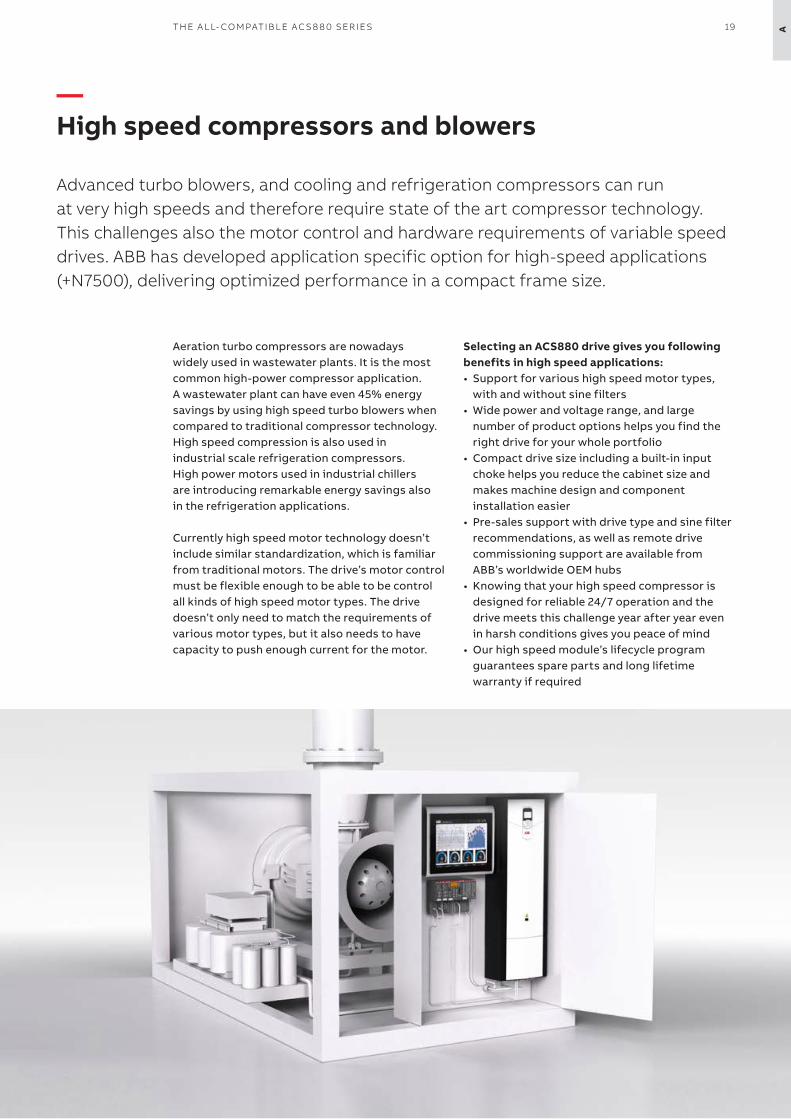
—High speed compressors and blowers
Advanced turbo blowers, and cooling and refrigeration compressors can run at very high speeds and therefore require state of the art compressor technology. This challenges also the motor control and hardware requirements of variable speeddrives. ABB has developed application specific option for high-speed applications(+N7500), delivering optimized performance in a compact frame size.
Aeration turbo compressors are nowadays widely used in wastewater plants. It is the most common high-power compressor application. A wastewater plant can have even 45% energy savings by using high speed turbo blowers when compared to traditional compressor technology. High speed compression is also used in industrial scale refrigeration compressors. High power motors used in industrial chillers are introducing remarkable energy savings also in the refrigeration applications.
Currently high speed motor technology doesn’tinclude similar standardization, which is familiarfrom traditional motors. The drive’s motor controlmust be flexible enough to be able to be controlall kinds of high speed motor types. The drivedoesn’t only need to match the requirements ofvarious motor types, but it also needs to havecapacity to push enough current for the motor.
Selecting an ACS880 drive gives you followingbenefits in high speed applications:• Support for various high speed motor types,
with and without sine filters• Wide power and voltage range, and large
number of product options helps you find the right drive for your whole portfolio
• Compact drive size including a built-in input choke helps you reduce the cabinet size and makes machine design and component installation easier
• Pre-sales support with drive type and sine filter recommendations, as well as remote drive commissioning support are available from ABB’s worldwide OEM hubs
• Knowing that your high speed compressor is designed for reliable 24/7 operation and the drive meets this challenge year after year even in harsh conditions gives you peace of mind
• Our high speed module’s lifecycle program guarantees spare parts and long lifetime warranty if required
19TH E A L L- CO M PATI B L E AC S 8 8 0 SER I E S A
20 A B B I N D U S TR I A L D R I V E S , AC S 8 8 0, S I N G L E D R I V E S , C ATA LO GA
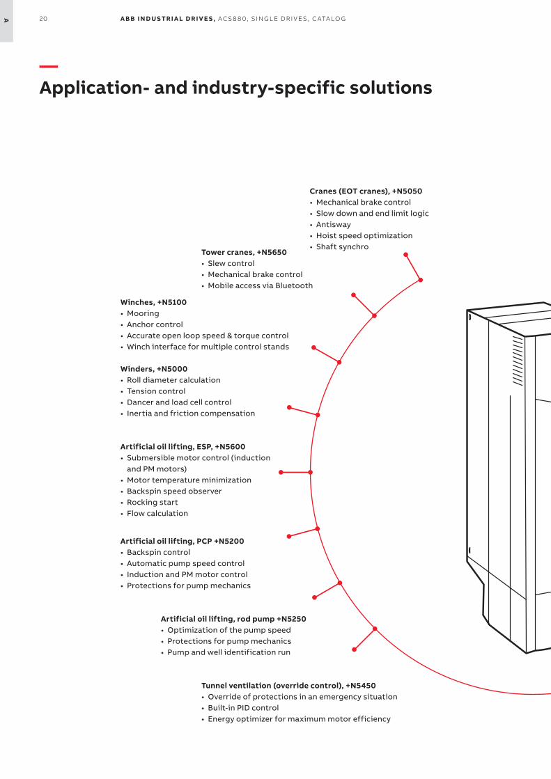
Cranes (EOT cranes), +N5050• Mechanical brake control• Slow down and end limit logic• Antisway• Hoist speed optimization• Shaft synchro
—Application- and industry-specific solutions
Tower cranes, +N5650• Slew control• Mechanical brake control• Mobile access via Bluetooth
Winches, +N5100• Mooring• Anchor control• Accurate open loop speed & torque control• Winch interface for multiple control stands
Winders, +N5000• Roll diameter calculation• Tension control• Dancer and load cell control• Inertia and friction compensation
Artificial oil lifting, ESP, +N5600• Submersible motor control (induction
and PM motors)• Motor temperature minimization• Backspin speed observer• Rocking start• Flow calculation
Artificial oil lifting, PCP +N5200• Backspin control• Automatic pump speed control• Induction and PM motor control• Protections for pump mechanics
Artificial oil lifting, rod pump +N5250• Optimization of the pump speed• Protections for pump mechanics• Pump and well identification run
Tunnel ventilation (override control), +N5450• Override of protections in an emergency situation• Built-in PID control• Energy optimizer for maximum motor efficiency

21TH E A L L- CO M PATI B L E AC S 8 8 0 SER I E S A
Textile (spinning), +N5500• Wobbulation function• Manual/auto off function• Production history
Test bench, +N5300• Fast communication• High torque accuracy and linearity• Acceleration damping• Minimized motor noise
Centrifuge, decanter, +N5150• Accurate speed and torque control, even without an encoder• Speed difference control of scroll drives for decanters
Cooling tower, +N5350• Support for slow, high-torque cooling tower motors• Trickle current to keep the motor warm and dry, preventing
condensation• Anti-windmill function
Chemical industry• Direct torque control with sine filters• Nine-year maintenance interval• Functionality that conforms with NAMUR requirements
Explosive atmospheres• Type approval with ABB Ex motors• ATEX-approved safe torque off, STO (+Q971) and thermistorprotection module (+L537)
Marine• Type approval from various key classification bodies (+C132)• Product certification process• 440 V variant
By working closely with customers over many years, ABB has developed application control programs and specific software features for specific applications and industries. This results in programs and features that include lessons learned from many customers, and that are designed to give you the flexibly to adapt the programs to your specific needs.
Advantages:• Enhanced application usability• Lower energy consumption• Increased safety• Reduced need for PLCs• Protected machinery• Optimized application productivity• Optimized time usage and lower
operational costs
Position control, +N5700• Ready-made motion control functions• IEC 61131 programming with PLCopen motion blocks• Synchronized drive to drive link
Anticavitation, +N5900• Extend the pump lifetime and secure the process• Detects cavitation and ensures optimal pump speed to remove it
High speed control firmware, +N7500• Application specific option for high-speed applications• Optimized performance in a compact frame size• Pre-sales support with drive type and sine filter recommendations

22 A B B I N D U S TR I A L D R I V E S , AC S 8 8 0, S I N G L E D R I V E S , C ATA LO GA
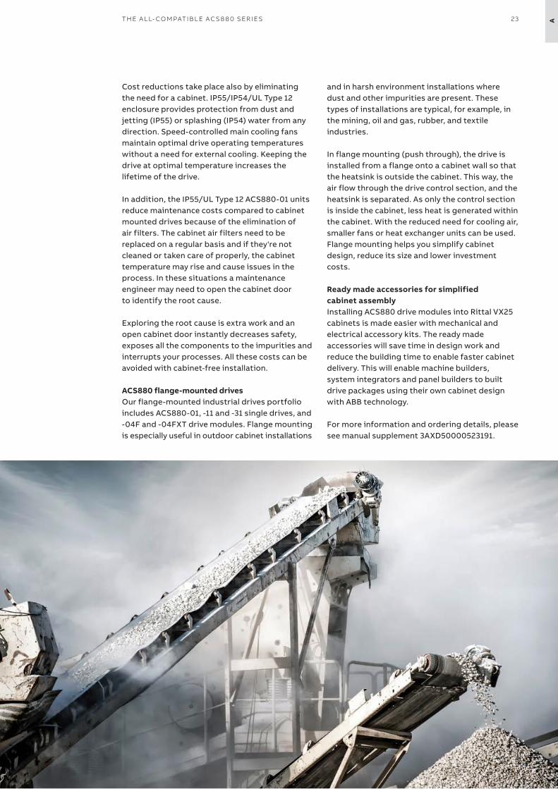
Higher enclosure class for rough environmentsThe ACS880 IP55/IP54/UL Type 12 units are an ideal choice for harsh environments, where impurities, such as dust or dirt waft in the air. Typical harsh environments include mining, cement, oil and gas, chemical, metal and wood processing industries and harsh outdoor conditions in desert and tropical environments. Higher protection class ensures smooth processes by reducing downtime.
The ACS880-01 units can be installed directly on the wall closer to the motor, which provides flexibility and simplifies installation. The robust, protective design ensures that no additional enclosures or components, such as dust filters and fans, are needed.
—Higher enclosure class and flange-mounted drives for installations in harsh conditions
Donʼt let dust, moisture or dirt interrupt your processes and drag down productivity. ACS880 IP55/IP54/UL Type 12 units, flange-mounted drives and Rittal VX25 cabinet accessories helps keeping your systems running even in tough conditions.
Protection against dust and water
Save space, increase safety and reduce overall costs
Maintain productivity in harsh conditions
Minimized downtime and flawless operation
Ordering codes
Description
+B056 IP55/UL Type 12 unit (ACS880-01, -11, -31)
+B055 IP54/UL Type 12 unit (ACS880-07, -17, -37, -07CLC, -17/37LC)
+C131 Vibration dampers (ACS880-01, -11, -31)
+C135 Flange mounting (ACS880-01, -11, -31)
Please contact ABB for Rittal VX25 cabinet accessories
ABB does not offer enclosures for potentially explosive atmospheres. ACS880LC liquid cooled modules can be installed to such 3rd party enclosures, as they are 100% liquid cooled.
Be productive, save money and keep it simpleIf the environment around your processes includes impurities, drives with lesser enclosure ratings are more likely to fail because they are not designed for harsh environments. A failure causes an interruption and instantly cuts down productivity and adds costs. Robust proven design, coated control boards, plated busbars, and IP55/IP54/UL Type 12 enclosure class *) or flange mounting *) combined with proper cabinet design (*) = option), and fully gasketed control panel section that maintains the IP rating even if the control panel is removed help keep your processes up and running in tough environments.
Installing the drive closer to the motor allows shorter motor cables to be used. Shorter cables not only cost less and are easier to handle, but they make it easier to fulfill EMC requirements and reduce the need for additional filters.
23TH E A L L- CO M PATI B L E AC S 8 8 0 SER I E S A
Cost reductions take place also by eliminatingthe need for a cabinet. IP55/IP54/UL Type 12 enclosure provides protection from dust and jetting (IP55) or splashing (IP54) water from any direction. Speed-controlled main cooling fans maintain optimal drive operating temperatures without a need for external cooling. Keeping the drive at optimal temperature increases the lifetime of the drive.
In addition, the IP55/UL Type 12 ACS880-01 units reduce maintenance costs compared to cabinet mounted drives because of the elimination of air filters. The cabinet air filters need to be replaced on a regular basis and if they're not cleaned or taken care of properly, the cabinet temperature may rise and cause issues in the process. In these situations a maintenance engineer may need to open the cabinet door to identify the root cause.
Exploring the root cause is extra work and anopen cabinet door instantly decreases safety,exposes all the components to the impurities andinterrupts your processes. All these costs can beavoided with cabinet-free installation.
ACS880 flange-mounted drivesOur flange-mounted industrial drives portfolio includes ACS880-01, -11 and -31 single drives, and -04F and -04FXT drive modules. Flange mounting is especially useful in outdoor cabinet installations
and in harsh environment installations where dust and other impurities are present. These types of installations are typical, for example, in the mining, oil and gas, rubber, and textile industries.
In flange mounting (push through), the drive is installed from a flange onto a cabinet wall so that the heatsink is outside the cabinet. This way, the air flow through the drive control section, and the heatsink is separated. As only the control section is inside the cabinet, less heat is generated within the cabinet. With the reduced need for cooling air, smaller fans or heat exchanger units can be used. Flange mounting helps you simplify cabinet design, reduce its size and lower investment costs.
Ready made accessories for simplified cabinet assemblyInstalling ACS880 drive modules into Rittal VX25 cabinets is made easier with mechanical and electrical accessory kits. The ready made accessories will save time in design work andreduce the building time to enable faster cabinetdelivery. This will enable machine builders, system integrators and panel builders to built drive packages using their own cabinet design with ABB technology.
For more information and ordering details, pleasesee manual supplement 3AXD50000523191.

24 A B B I N D U S TR I A L D R I V E S , AC S 8 8 0, S I N G L E D R I V E S , C ATA LO G
25EU ECO D E SI G N R EG U L ATI O N
B—EU Ecodesign Regulation
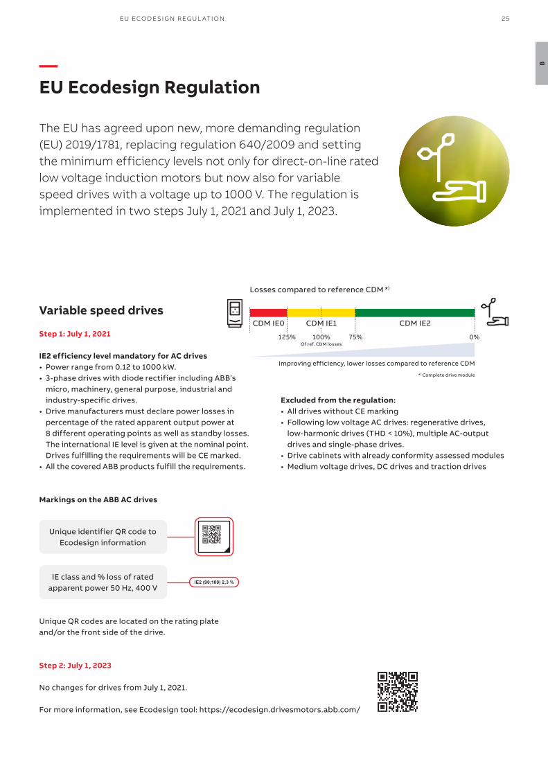
The EU has agreed upon new, more demanding regulation (EU) 2019/1781, replacing regulation 640/2009 and setting the minimum efficiency levels not only for direct-on-line rated low voltage induction motors but now also for variable speed drives with a voltage up to 1000 V. The regulation is implemented in two steps July 1, 2021 and July 1, 2023.
Variable speed drives
Step 1: July 1, 2021
IE2 efficiency level mandatory for AC drives• Power range from 0.12 to 1000 kW.• 3-phase drives with diode rectifier including ABB’s
micro, machinery, general purpose, industrial and industry-specific drives.
• Drive manufacturers must declare power losses in percentage of the rated apparent output power at 8 different operating points as well as standby losses. The international IE level is given at the nominal point. Drives fulfilling the requirements will be CE marked.
• All the covered ABB products fulfill the requirements.
Excluded from the regulation:• All drives without CE marking• Following low voltage AC drives: regenerative drives,
low-harmonic drives (THD < 10%), multiple AC-output drives and single-phase drives.
• Drive cabinets with already conformity assessed modules• Medium voltage drives, DC drives and traction drives
Unique identifier QR code toEcodesign information
IE class and % loss of ratedapparent power 50 Hz, 400 V
Step 2: July 1, 2023
No changes for drives from July 1, 2021.
For more information, see Ecodesign tool: https://ecodesign.drivesmotors.abb.com/
IE2 (90;100) 2,3 %
Unique QR codes are located on the rating plate and/or the front side of the drive.
Markings on the ABB AC drives
CDM IE1
Improving efficiency, lower losses compared to reference CDM
*) Complete drive module
CDM IE0 CDM IE2
Losses compared to reference CDM *)
0%75%100%Of ref. CDM losses
125%

26 A B B I N D U S TR I A L D R I V E S , AC S 8 8 0, S I N G L E D R I V E S , C ATA LO G
C
—Technical data
Mains connectionVoltage and power range
3-phase, UN2 208 to 240 V, +10%/-15% (-01)3-phase, UN3 380 to 415 V, +10%/-15% (-01, -11, -31),±10% (-07,-17-37)3-phase, UN5 380 to 500 V, +10%/-15% (-01, -11, -31),±10% (-07,-17-37)3-phase, UN7 525 to 690 V, +10%/-15% (-01),±10% (-07,-17,-37, -07CLC, -17/37LC)0.55 to 250 kW (-01)2.2 to 110 kW (-11, -31)45 to 2800 kW (-07)45 to 3200 kW (-17, -37)250 to 6000 kW (-07CLC, -17/37LC)
Frequency 50/60 Hz ±5%
Power factorACS880-01, -07, -07CLC
ACS880-11, -31, -17, -37, -17/37LC
cosϕ = 0.98 (fundamental)cosϕ = 0.93 to 0.95 (total) cosϕ = 1 (fundamental)
Efficiency (at nominal power)
ACS880-01, -07, -07CLC, -17/37LC: 98%ACS880-11, -31, -17, -37: 97%
Motor connection
Voltage 3-phase output voltage 0 to UN2 /UN3 /UN5 /UN7
Frequency 0 to ±598 Hz 1) 2)
Motor control Direct torque control (DTC)
Torque controlOpen loopClosed loop
Open loopClosed loop
Torque step rise time:<5 ms with nominal torque<5 ms with nominal torqueNon-linearity:± 4% with nominal torque± 3% with nominal torque
Speed controlOpen loopClosed loop
Open loopClosed loop
Static accuracy:10% of motor nominal slip0.01% of nominal speedDynamic accuracy:0.3 to 0.4% seconds with 100% torque step0.1 to 0.2% seconds with 100% torque step
Product complianceCE, UKCALow Voltage Directive 2014/35/EU according to EN 61800-5-1:2007Machinery Directive 2006/42/ECEMC Directive 2014/30/EUATEX Directive 2014/34/EU, EN 50495Quality assurance system ISO 9001 and Environmental system ISO 14001Ecodesign Directive 2009/125/EC and its implementation regulation 2019/1781/EURoHS 2011/65/EU and Delegated Directive (EU) 2015/836 RCM, EAC 4)
TÜV Nord certification for functional safety 3)
ATEX-certified safe disconnection function and thermistor and PT100 protection functions, Ex II (2) GD 2) 7)
UKEX Type Examination certificates for safe disconnection function and thermistor and PT100 protection functions, Ex II (2) GD 2) 7)
Marine type approvals for -01: ABS, Bureau veritas, CCS, DNV GL, KR,Lloydʼs, NK, RINA, RMRS. For other drives, see https://new.abb.com/drives/segments/marine/marine-type-approvalsUL, CSA:-01: cULus listed according to UL 508C and CSA C22.2 No. 274, CSA certified according to CSA C22.2 No. 274.-11, -31: cULus listed according to UL 61800-5-1 and CSA C22.2 No. 274-07, -17, -37, -07LC, -17LC, -37LC: cULus listed according to UL 508A and CSA C22.2 No. 14, CSA certified according to CSA C22.2 No. 14 8)
-07CLC, -07LC, -17/37LC: cULus listed according to UL 508A and CSA C22.2 No. 14, CSA pending.
EMC according to EN 61800-3: 2004 + A1: 2012. See page 73.
Category C3 and C2 with internal option or as standard.
Environmental limitsAmbient temperatureTransport StorageOperation area (air-cooled)
(liquid-cooled)
-40 to +70 °C-40 to +70 °C-15 to +40 °C as standard (-01, -11, -31)0 to +40 °C as standard (-07, -17, -37)+40 to +55 °C with derating of 1%/1 °C (-01, -11, -31) +40 to +50 °C with derating of 1%/1 °C (-07,-17,-37)0 to +45 °C as standard (-07CLC, -17/37LC)+45 to 55 °C with derating of 0.5%/1 °C (-07CLC, -17/37LC)
Cooling methodAir-cooledLiquid-cooled -07CLC, -17/37LC
Without liquid-cooling unit
With liquid-cooling unit
Dry clean airDirect liquid-cooling, Antifrogen® L
Incoming coolant temperature0 to +40 °C as standard+40 to +45 °C with derating of 2%/1 °C+45 to +50 °C with derating of 2%/1 °C or 6%/1 °C 5)
Incoming coolant temperature0 to +36 °C as standard+36 to +46 °C with derating of 2%/1 °C
Altitude0 to 1,000 m1,000 to 4,000 m
Without deratingWith derating of 1%/ 100 m 6)
Relative humidity 5 to 95%, no condensation allowed
Degree of protectionIP20IP21IP22IP42IP54IP55
Option (-01, -11, -31)Standard (-01, -11, -31)Standard (-07, -17, -37)Standard (-07CLC, -17/37LC). Option (-07, -17, -37)Option (-07, -17, -37, -07CLC, -17/37LC)Option (-01, -11, -31)
Paint color RAL 9017/9002 (-01, -11, -31), RAL 9017/7035 (-07, -17, -37, -07CLC, -17/37LC)
Pollution degree PD 2
Contamination levels
No conductive dust allowed
Storage IEC 60721-3-1:1997, IEC 60721-3-1, Class 1C2 (chemical gases), Class 1S2 (solid particles) *)
Operation IEC 60721-3-3:2002, IEC 60721-3-3, Class 3C2 (chemical gases), Class 3S2 (solid particles) *)
Transportation IEC 60721-3-2:1997, IEC 60721-3-2, Class 2C2 (chemical gases), Class 2S2 (solid particles) *)
Built-in functional safety. See pages 70-71.For safe torqueoff (STO) andsafety functionsmodulesSafety over fieldbus
EN/IEC 61800-5-2, IEC 61508: SIL 3,IEC 61511: SIL 3,EN/IEC 62061EN ISO 13849-1: PL e - TÜV Nord certified
PROFIsafe over PROFINET, certified
*) C = Chemically active substances. S = Mechanically active substances.1) Operation above 120 Hz might require type-specific derating.
For higher output frequencies, please contact your local ABB office.Output filters may limit the output frequency. See product specific hardware manual for details.
2) Safe disconnection function (+Q971),Thermistor protection function (+L537+Q971)PTC/PT100 thermal motor protection for -07/17/37/17LC/37LC(+L513/L514+Q971)
3) For available certificates, see http://new.abb.com/drives/functional-safety
4) EAC directives: TR CU 020/2011 (EMC directive); TR CU 004/2011 (low voltage directive) EAC has replaced GOST R
5) See product specific hardware manual for detailed derating rules6) Derating reduced by lower than 40 oC ambient temperature7) Not applicable for -07CLC8) In operation, UL/CSA panel shop standards that ACS880-x7 air & LC
comply with, only allow ambient temperature of 0…40 °C
27H OW TO SEL EC T A D R I V E
D
35C A B I N E T- B U I LT D R I V E S
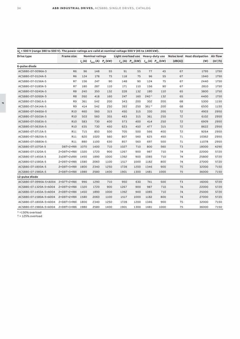
F
Nominal ratings
IN Rated current available continuously without overloadability at 40 °C.
PN Typical motor power in no-overload use.
Maximum output current
Imax Maximum output current. Available for 10 seconds at start, then as long as allowed by drive temperature.
Light-overload use
ILd Continuous current allowing 110% ILd for 1 minute every 5 minutes at 40 °C.
PLd Typical motor power in light-overload use.
Heavy-duty use
IHd Continuous current allowing 150% IHd for 1 minute every 5 minutes at 40 °C.
PHd Typical motor power in heavy-duty use.
The ratings apply at 40 °C ambient temperature. At higher temperatures (up to 50 °C), the derating is 1%/1 °C.Operation above 150 Hz might require type specific derating.
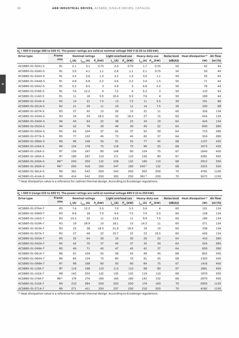
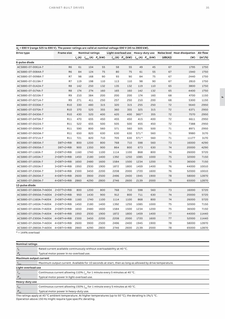
UN = 690 V (range 525 to 690 V). The power ratings are valid at nominal voltage 690 V (45 to 2800 kW).
Drive type Frame size Nominal ratings Light overload use Heavy-duty use Noise level Heat dissipation Air flow
IN (A) IMAX (A) PN (kW) ILd (A) PLd (kW) IHd (A) PHd (kW) (dB(A)) (W) (m3/h)
6-pulse diode
ACS880-07-0061A-7 R6 61 104 55 58 55 49 45 67 1795 1750
ACS880-07-0084A-7 R6 84 124 75 80 75 61 55 67 1940 1750
ACS880-07-0098A-7 R7 98 168 90 93 90 84 75 67 2440 1750
ACS880-07-0119A-7 R7 119 198 110 113 110 98 90 67 2810 1750
ACS880-07-0142A-7 R8 142 250 132 135 132 119 110 65 3800 1750
ACS880-07-0174A-7 R8 174 274 160 165 160 142 132 65 4400 1750
ACS880-07-0210A-7 R9 210 384 200 200 200 174 160 68 4700 1150
ACS880-07-0271A-7 R9 271 411 250 257 250 210 200 68 5300 1150
ACS880-07-0330A-7 R10 330 480 315 320 315 255 250 72 5640 2950
ACS880-07-0370A-7 R10 370 520 355 360 355 325 315 72 6371 2950
ACS880-07-0430A-7 R10 430 520 400 420 400 360 4) 355 72 7570 2950
ACS880-07-0470A-7 R11 470 655 450 455 450 415 400 72 6611 2950
ACS880-07-0522A-7 R11 522 655 500 505 500 455 450 72 7388 2950
ACS880-07-0590A-7 R11 590 800 560 571 560 505 500 71 8971 2950
ACS880-07-0650A-7 R11 650 820 630 630 630 571 4) 560 71 9980 3170
ACS880-07-0721A-7 R11 721 820 710 705 630 571 4) 560 71 11177 3170
ACS880-07-0800A-7 D8T+2×R8i 800 1200 800 768 710 598 560 73 16000 4290
ACS880-07-0900A-7 D8T+2×R8i 900 1350 900 864 800 673 630 74 20000 4290
ACS880-07-1160A-7 2×D8T+2×R8i 1160 1740 1100 1114 1100 868 800 74 26000 5720
ACS880-07-1450A-7 2×D8T+3×R8i 1450 2180 1400 1392 1250 1085 1000 75 32000 7150
ACS880-07-1650A-7 2×D8T+3×R8i 1650 2480 1600 1584 1500 1234 1200 75 36500 7150
ACS880-07-1950A-7 3×D8T+4×R8i 1950 2930 1900 1872 1800 1459 1400 76 44000 10010
ACS880-07-2300A-7 3×D8T+4×R8i 2300 3450 2200 2208 2000 1720 1600 76 52000 10010
ACS880-07-2600A-7 4×D8T+5×R8i 2600 3900 2500 2496 2400 1945 1900 78 58000 12870
ACS880-07-2860A-7 4×D8T+5×R8i 2860 4290 2800 2746 2600 2139 2000 78 65000 12870
12-pulse diode
ACS880-07-0800A-7+A004 2×D7T+2×R8i 800 1200 800 768 710 598 560 73 16000 5720
ACS880-07-0950A-7+A004 2×D8T+2×R8i 950 1430 900 912 800 711 630 74 20000 5720
ACS880-07-1160A-7+A004 2×D8T+2×R8i 1160 1740 1100 1114 1100 868 800 74 26000 5720
ACS880-07-1450A-7+A004 2×D8T+3×R8i 1450 2180 1400 1392 1250 1085 1000 75 32000 7150
ACS880-07-1650A-7+A004 2×D8T+3×R8i 1650 2480 1600 1584 1500 1234 1200 75 36500 7150
ACS880-07-1950A-7+A004 4×D8T+4×R8i 1950 2930 1900 1872 1800 1459 1400 77 44000 11440
ACS880-07-2300A-7+A004 4×D8T+4×R8i 2300 3450 2200 2208 2000 1720 1600 77 52000 11440
ACS880-07-2600A-7+A004 4×D8T+5×R8i 2600 3900 2500 2496 2400 1945 1900 78 58000 12870
ACS880-07-2860A-7+A004 4×D8T+5×R8i 2860 4290 2800 2746 2600 2139 2000 78 65000 128704) = 144% overload
29WA L L- M O U NTED D R I V E S
E
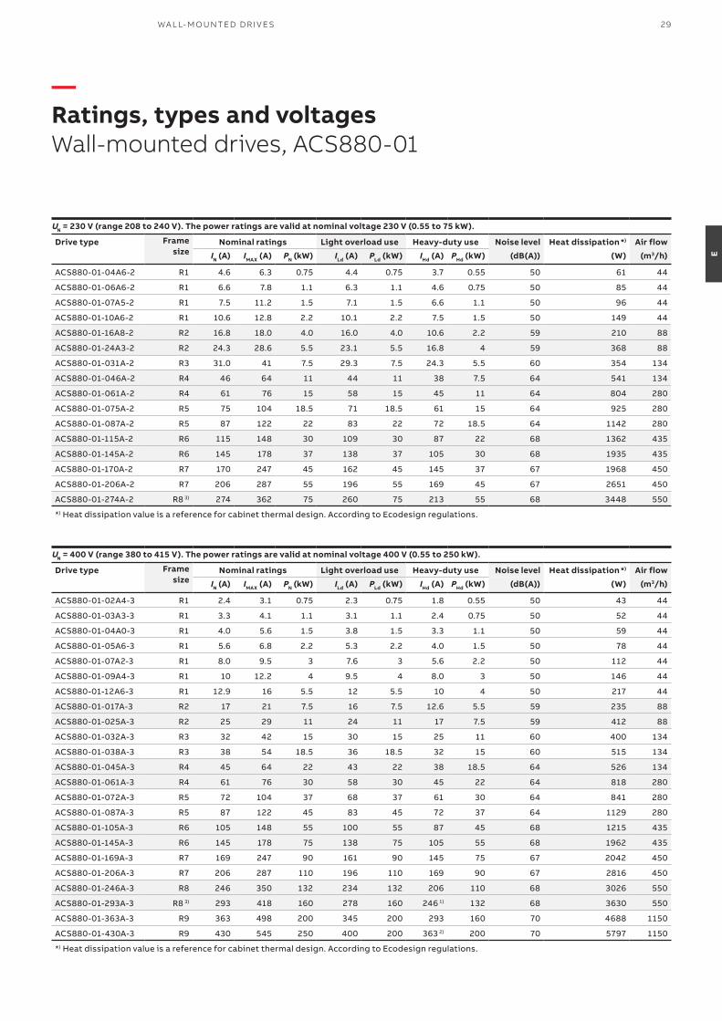
—Ratings, types and voltagesWall-mounted drives, ACS880-01
UN = 230 V (range 208 to 240 V). The power ratings are valid at nominal voltage 230 V (0.55 to 75 kW).
Drive type Frame size
Nominal ratings Light overload use Heavy-duty use Noise level Heat dissipation *) Air flow
IN (A) IMAX (A) PN (kW) ILd (A) PLd (kW) IHd (A) PHd (kW) (dB(A)) (W) (m3/h)
ACS880-01-04A6-2 R1 4.6 6.3 0.75 4.4 0.75 3.7 0.55 50 61 44
ACS880-01-06A6-2 R1 6.6 7.8 1.1 6.3 1.1 4.6 0.75 50 85 44
ACS880-01-07A5-2 R1 7.5 11.2 1.5 7.1 1.5 6.6 1.1 50 96 44
ACS880-01-10A6-2 R1 10.6 12.8 2.2 10.1 2.2 7.5 1.5 50 149 44
ACS880-01-16A8-2 R2 16.8 18.0 4.0 16.0 4.0 10.6 2.2 59 210 88
ACS880-01-24A3-2 R2 24.3 28.6 5.5 23.1 5.5 16.8 4 59 368 88
ACS880-01-031A-2 R3 31.0 41 7.5 29.3 7.5 24.3 5.5 60 354 134
ACS880-01-046A-2 R4 46 64 11 44 11 38 7.5 64 541 134
ACS880-01-061A-2 R4 61 76 15 58 15 45 11 64 804 280
ACS880-01-075A-2 R5 75 104 18.5 71 18.5 61 15 64 925 280
ACS880-01-087A-2 R5 87 122 22 83 22 72 18.5 64 1142 280
ACS880-01-115A-2 R6 115 148 30 109 30 87 22 68 1362 435
ACS880-01-145A-2 R6 145 178 37 138 37 105 30 68 1935 435
ACS880-01-170A-2 R7 170 247 45 162 45 145 37 67 1968 450
ACS880-01-206A-2 R7 206 287 55 196 55 169 45 67 2651 450
ACS880-01-274A-2 R8 3) 274 362 75 260 75 213 55 68 3448 550
*) Heat dissipation value is a reference for cabinet thermal design. According to Ecodesign regulations.
UN = 400 V (range 380 to 415 V). The power ratings are valid at nominal voltage 400 V (0.55 to 250 kW).
Drive type Frame size
Nominal ratings Light overload use Heavy-duty use Noise level Heat dissipation *) Air flow
IN (A) IMAX (A) PN (kW) ILd (A) PLd (kW) IHd (A) PHd (kW) (dB(A)) (W) (m3/h)
ACS880-01-02A4-3 R1 2.4 3.1 0.75 2.3 0.75 1.8 0.55 50 43 44
ACS880-01-03A3-3 R1 3.3 4.1 1.1 3.1 1.1 2.4 0.75 50 52 44
ACS880-01-04A0-3 R1 4.0 5.6 1.5 3.8 1.5 3.3 1.1 50 59 44
ACS880-01-05A6-3 R1 5.6 6.8 2.2 5.3 2.2 4.0 1.5 50 78 44
ACS880-01-07A2-3 R1 8.0 9.5 3 7.6 3 5.6 2.2 50 112 44
ACS880-01-09A4-3 R1 10 12.2 4 9.5 4 8.0 3 50 146 44
ACS880-01-12A6-3 R1 12.9 16 5.5 12 5.5 10 4 50 217 44
ACS880-01-017A-3 R2 17 21 7.5 16 7.5 12.6 5.5 59 235 88
ACS880-01-025A-3 R2 25 29 11 24 11 17 7.5 59 412 88
ACS880-01-032A-3 R3 32 42 15 30 15 25 11 60 400 134
ACS880-01-038A-3 R3 38 54 18.5 36 18.5 32 15 60 515 134
ACS880-01-045A-3 R4 45 64 22 43 22 38 18.5 64 526 134
ACS880-01-061A-3 R4 61 76 30 58 30 45 22 64 818 280
ACS880-01-072A-3 R5 72 104 37 68 37 61 30 64 841 280
ACS880-01-087A-3 R5 87 122 45 83 45 72 37 64 1129 280
ACS880-01-105A-3 R6 105 148 55 100 55 87 45 68 1215 435
ACS880-01-145A-3 R6 145 178 75 138 75 105 55 68 1962 435
ACS880-01-169A-3 R7 169 247 90 161 90 145 75 67 2042 450
ACS880-01-206A-3 R7 206 287 110 196 110 169 90 67 2816 450
ACS880-01-246A-3 R8 246 350 132 234 132 206 110 68 3026 550
ACS880-01-293A-3 R8 3) 293 418 160 278 160 246 1) 132 68 3630 550
ACS880-01-363A-3 R9 363 498 200 345 200 293 160 70 4688 1150
ACS880-01-430A-3 R9 430 545 250 400 200 363 2) 200 70 5797 1150
*) Heat dissipation value is a reference for cabinet thermal design. According to Ecodesign regulations.
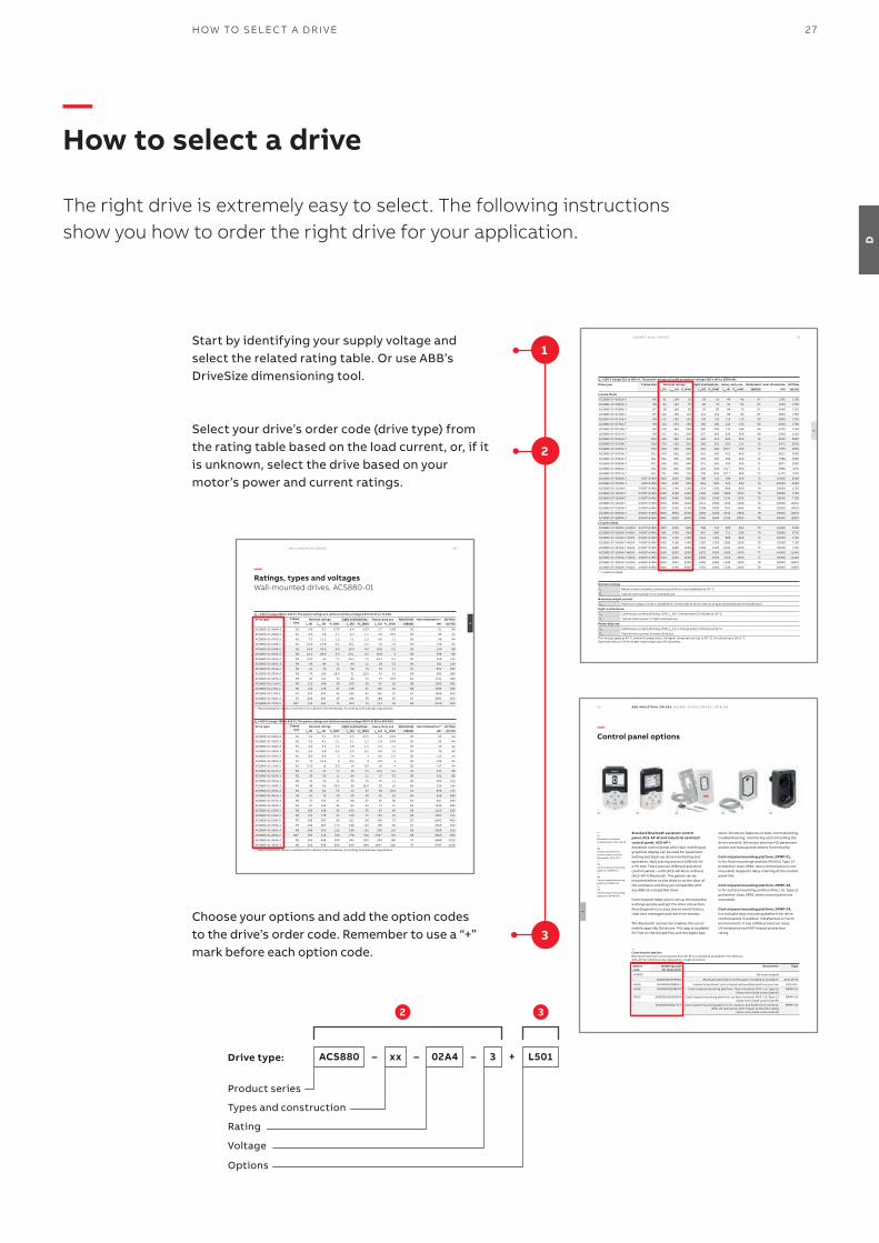
Select your drive’s order code (drive type) from the rating table based on the load current, or, if it is unknown, select the drive based on your motor’s power and current ratings.
Start by identifying your supply voltage and select the related rating table. Or use ABB’s DriveSize dimensioning tool.
2 3
Drive type:
Product series
Types and construction
Rating
Voltage
Options
ACS880 02A4 L501+ xx 3–––
—How to select a drive
The right drive is extremely easy to select. The following instructions show you how to order the right drive for your application.
2
1
Choose your options and add the option codes to the drive’s order code. Remember to use a “+” mark before each option code.
3
60
L
A B B I N D U S TR I A L D R I V E S , AC S 8 8 0, S IN G L E D R I V E S , C ATA LO G
—02
—01
—Control panel options
Standard Bluetooth assistant control panel, ACS-AP-W and Industrial assistant control panel, ACS-AP-IAssistant control panel with clear multilingual graphical display can be used for parameter setting and back-up, drive monitoring and operation, fault tracing and as a USB link for a PC tool. There are two different assistant control panels – with (ACS-AP-W) or without (ACS-AP-I) Bluetooth. The panels can be mounted either on the drive or on the door of the enclosure and they are compatible with any ABB all-compatible drive.
Control panel helps you to set up the essential settings quickly and get the drive into action. Also diagnostics is easy due to event history, clear text messages and real-time stamps.
The Bluetooth connection enables the use of mobile apps like Drivetune. This app is available for free on the Google Play and the Apple App
Option code
Ordering code for loose item
Description Type
+0J400 – No control panel –
– 3AXD0000025965 Bluetooth Assistant control panel. Included as standard. ACS-AP-W
+J425 3AUA0000088311 Industrial assistant control panel without Bluetooth connection ACS-AP-I
+J410 3AUA0000108878 Control panel mounting platform, flush mounted, IP54 / UL Type 12 (does not include control panel)
DPMP-01
+J413 3AXD50000009374 Control panel mounting platform, surface mounted, IP65 / UL Type 12 (does not include control panel)
DPMP-02
– 3AXD50000217717 Control panel mounting platform for outdoor and harsh environments, IP66, UV resistance, IK07 impact protection rating
(does not include control panel)
DPMP-04
—Control panel optionsBluetooth Assistant control panel ACS-AP-W is included as standard in the delivery.ACS-AP-W (+J400) can be replaced by +J options below.
—01 Bluetooth assistant control panel, ACS-AP-W—02 Industrial assistant control panel without Bluetooth, ACS-AP-I—03 Control panel mounting platform DPMP-01—04 Control panel mounting platform DPMP-02—05 Control panel mounting platform, DPMP-04
—03
store. Drivetune features include: commissioning, troubleshooting, monitoring and controlling the drive remotely. Drivetune also has full parameter access and backup and restore functionality.
Control panel mounting platform, DPMP-01,is for flush mountings and has IP54/UL Type 12 protection class (IP20, when control panel is not mounted). Supports daisy chaining of the control panel link.
Control panel mounting platform, DPMP-02,is for surface mounting and has IP65 / UL Type 12 protection class (IP20, when control panel not mounted).
Control panel mounting platform, DPMP-04, is a lockable door mounting platform for drive control panels in outdoor installations or harsh environments. It has a IP66 protection class, UV resistance and IK07 impact protection rating.
—04
—05
28 A B B I N D U S TR I A L D R I V E S , AC S 8 8 0, S I N G L E D R I V E S , C ATA LO G
E
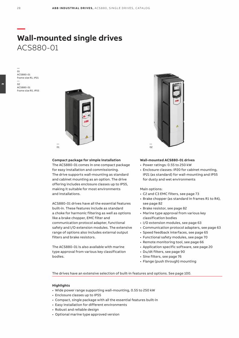
—Wall-mounted single drivesACS880-01
Compact package for simple installationThe ACS880-01 comes in one compact package for easy installation and commissioning. The drive supports wall-mounting as standard and cabinet mounting as an option. The drive offering includes enclosure classes up to IP55, making it suitable for most environments and installations.
ACS880-01 drives have all the essential features built-in. These features include as standard a choke for harmonic filtering as well as options like a brake chopper, EMC filter and communication protocol adapter, functional safety and I/O extension modules. The extensive range of options also includes external output filters and brake resistors.
The ACS880-01 is also available with marine type approval from various key classification bodies.
Wall-mounted ACS880-01 drives• Power ratings: 0.55 to 250 kW• Enclosure classes: IP20 for cabinet mounting,
IP21 (as standard) for wall-mounting and IP55 for dusty and wet environments
Main options:• C2 and C3 EMC filters, see page 73• Brake chopper (as standard in frames R1 to R4),
see page 82 • Brake resistor, see page 82 • Marine type approval from various key
classification bodies• I/O extension modules, see page 63 • Communication protocol adapters, see page 63 • Speed feedback interfaces, see page 65 • Functional safety modules, see page 70• Remote monitoring tool, see page 66• Application specific software, see page 20• Du/dt filters, see page 90• Sine filters, see page 76• Flange (push through) mounting
Highlights• Wide power range supporting wall-mounting, 0.55 to 250 kW• Enclosure classes up to IP55• Compact, single package with all the essential features built-in• Easy installation for different environments• Robust and reliable design• Optional marine type approved version
The drives have an extensive selection of built-in features and options. See page 100.
—02
—01
—01 ACS880-01 frame size R1, IP21—02 ACS880-01 frame size R5, IP55
29WA L L- M O U NTED D R I V E S
E
—Ratings, types and voltagesWall-mounted drives, ACS880-01
UN = 230 V (range 208 to 240 V). The power ratings are valid at nominal voltage 230 V (0.55 to 75 kW).
Drive type Frame size
Nominal ratings Light overload use Heavy-duty use Noise level Heat dissipation *) Air flow
IN (A) IMAX (A) PN (kW) ILd (A) PLd (kW) IHd (A) PHd (kW) (dB(A)) (W) (m3/h)
ACS880-01-04A6-2 R1 4.6 6.3 0.75 4.4 0.75 3.7 0.55 50 61 44
ACS880-01-06A6-2 R1 6.6 7.8 1.1 6.3 1.1 4.6 0.75 50 85 44
ACS880-01-07A5-2 R1 7.5 11.2 1.5 7.1 1.5 6.6 1.1 50 96 44
ACS880-01-10A6-2 R1 10.6 12.8 2.2 10.1 2.2 7.5 1.5 50 149 44
ACS880-01-16A8-2 R2 16.8 18.0 4.0 16.0 4.0 10.6 2.2 59 210 88
ACS880-01-24A3-2 R2 24.3 28.6 5.5 23.1 5.5 16.8 4 59 368 88
ACS880-01-031A-2 R3 31.0 41 7.5 29.3 7.5 24.3 5.5 60 354 134
ACS880-01-046A-2 R4 46 64 11 44 11 38 7.5 64 541 134
ACS880-01-061A-2 R4 61 76 15 58 15 45 11 64 804 280
ACS880-01-075A-2 R5 75 104 18.5 71 18.5 61 15 64 925 280
ACS880-01-087A-2 R5 87 122 22 83 22 72 18.5 64 1142 280
ACS880-01-115A-2 R6 115 148 30 109 30 87 22 68 1362 435
ACS880-01-145A-2 R6 145 178 37 138 37 105 30 68 1935 435
ACS880-01-170A-2 R7 170 247 45 162 45 145 37 67 1968 450
ACS880-01-206A-2 R7 206 287 55 196 55 169 45 67 2651 450
ACS880-01-274A-2 R8 3) 274 362 75 260 75 213 55 68 3448 550
*) Heat dissipation value is a reference for cabinet thermal design. According to Ecodesign regulations.
UN = 400 V (range 380 to 415 V). The power ratings are valid at nominal voltage 400 V (0.55 to 250 kW).
Drive type Frame size
Nominal ratings Light overload use Heavy-duty use Noise level Heat dissipation *) Air flow
IN (A) IMAX (A) PN (kW) ILd (A) PLd (kW) IHd (A) PHd (kW) (dB(A)) (W) (m3/h)
ACS880-01-02A4-3 R1 2.4 3.1 0.75 2.3 0.75 1.8 0.55 50 43 44
ACS880-01-03A3-3 R1 3.3 4.1 1.1 3.1 1.1 2.4 0.75 50 52 44
ACS880-01-04A0-3 R1 4.0 5.6 1.5 3.8 1.5 3.3 1.1 50 59 44
ACS880-01-05A6-3 R1 5.6 6.8 2.2 5.3 2.2 4.0 1.5 50 78 44
ACS880-01-07A2-3 R1 8.0 9.5 3 7.6 3 5.6 2.2 50 112 44
ACS880-01-09A4-3 R1 10 12.2 4 9.5 4 8.0 3 50 146 44
ACS880-01-12A6-3 R1 12.9 16 5.5 12 5.5 10 4 50 217 44
ACS880-01-017A-3 R2 17 21 7.5 16 7.5 12.6 5.5 59 235 88
ACS880-01-025A-3 R2 25 29 11 24 11 17 7.5 59 412 88
ACS880-01-032A-3 R3 32 42 15 30 15 25 11 60 400 134
ACS880-01-038A-3 R3 38 54 18.5 36 18.5 32 15 60 515 134
ACS880-01-045A-3 R4 45 64 22 43 22 38 18.5 64 526 134
ACS880-01-061A-3 R4 61 76 30 58 30 45 22 64 818 280
ACS880-01-072A-3 R5 72 104 37 68 37 61 30 64 841 280
ACS880-01-087A-3 R5 87 122 45 83 45 72 37 64 1129 280
ACS880-01-105A-3 R6 105 148 55 100 55 87 45 68 1215 435
ACS880-01-145A-3 R6 145 178 75 138 75 105 55 68 1962 435
ACS880-01-169A-3 R7 169 247 90 161 90 145 75 67 2042 450
ACS880-01-206A-3 R7 206 287 110 196 110 169 90 67 2816 450
ACS880-01-246A-3 R8 246 350 132 234 132 206 110 68 3026 550
ACS880-01-293A-3 R8 3) 293 418 160 278 160 246 1) 132 68 3630 550
ACS880-01-363A-3 R9 363 498 200 345 200 293 160 70 4688 1150
ACS880-01-430A-3 R9 430 545 250 400 200 363 2) 200 70 5797 1150
*) Heat dissipation value is a reference for cabinet thermal design. According to Ecodesign regulations.
30 A B B I N D U S TR I A L D R I V E S , AC S 8 8 0, S I N G L E D R I V E S , C ATA LO G
E
UN = 500 V (range 380 to 500 V). The power ratings are valid at nominal voltage 500 V (0.55 to 250 kW).
Drive type Frame size
Nominal ratings Light overload use Heavy-duty use Noise level Heat dissipation *) Air flow
IN (A) IMAX (A) PN (kW) ILd (A) PLd (kW) IHd (A) PHd (kW) (dB(A)) (W) (m3/h)
ACS880-01-02A1-5 R1 2.1 3.1 0.75 2.0 0.75 1.7 0.55 50 42 44
ACS880-01-03A0-5 R1 3.0 4.1 1.1 2.8 1.1 2.1 0.75 50 50 44
ACS880-01-03A4-5 R1 3.4 5.6 1.5 3.2 1.5 3.0 1.1 50 55 44
ACS880-01-04A8-5 R1 4.8 6.8 2.2 4.6 2.2 3.4 1.5 50 71 44
ACS880-01-05A2-5 R1 5.2 9.5 3 4.9 3 4.8 2.2 50 76 44
ACS880-01-07A6-5 R1 7.6 12.2 4 7.2 4 5.2 3 50 110 44
ACS880-01-11A0-5 R1 11 16 5.5 10.4 5.5 7.6 4 50 180 44
ACS880-01-014A-5 R2 14 21 7.5 13 7.5 11 5.5 59 191 88
ACS880-01-021A-5 R2 21 29 11 19 11 14 7.5 59 330 88
ACS880-01-027A-5 R3 27 42 15 26 15 21 11 60 326 134
ACS880-01-034A-5 R3 34 54 18.5 32 18.5 27 15 60 454 134
ACS880-01-040A-5 R4 40 64 22 38 22 34 19 64 424 134
ACS880-01-052A-5 R4 52 76 30 49 30 40 22 64 600 280
ACS880-01-065A-5 R5 65 104 37 62 37 52 30 64 715 280
ACS880-01-077A-5 R5 77 122 45 73 45 65 37 64 916 280
ACS880-01-096A-5 R6 96 148 55 91 55 77 45 68 1157 435
ACS880-01-124A-5 R6 124 178 75 118 75 96 55 68 1673 435
ACS880-01-156A-5 R7 156 247 90 148 90 124 75 67 1840 450
ACS880-01-180A-5 R7 180 287 110 171 110 156 90 67 2281 450
ACS880-01-240A-5 R8 4) 240 350 132 228 132 180 110 68 2912 550
ACS880-01-260A-5 R8 3) 260 418 160 247 160 240 1) 132 68 3325 550
ACS880-01-361A-5 R9 361 542 200 343 200 302 200 70 4781 1150
ACS880-01-414A-5 R9 414 542 250 393 250 361 2) 200 70 5672 1150
*) Heat dissipation value is a reference for cabinet thermal design. According to Ecodesign regulations.
UN = 690 V (range 525 to 690 V). The power ratings are valid at nominal voltage 690 V (4 to 250 kW).
Drive type Frame size
Nominal ratings Light overload use Heavy-duty use Noise level Heat dissipation *) Air flow
IN (A) IMAX (A) PN (kW) ILd (A) PLd (kW) IHd (A) PHd (kW) (dB(A)) (W) (m3/h)
ACS880-01-07A4-7 R3 7.4 12.2 5.5 7.0 5.5 5.6 4 60 101 134
ACS880-01-09A9-7 R3 9.9 18 7.5 9.4 7.5 7.4 5.5 60 128 134
ACS880-01-14A3-7 R3 14.3 22 11 13.6 11 9.9 7.5 60 189 134
ACS880-01-019A-7 R3 19 28.9 15 18.1 15 14.3 11 60 271 134
ACS880-01-023A-7 R3 23 38 18.5 21.9 18.5 19 15 60 338 134
ACS880-01-027A-7 R3 27 46 22 25.7 22 23 18.5 60 426 134
ACS880-01-035A-7 R5 35 64 30 33 30 26 22 64 416 280
ACS880-01-042A-7 R5 42 70 37 40 37 35 30 64 524 280
ACS880-01-049A-7 R5 49 71 45 47 45 42 37 64 650 280
ACS880-01-061A-7 R6 61 104 55 58 55 49 45 68 852 435
ACS880-01-084A-7 R6 84 124 75 80 75 61 55 68 1303 435
ACS880-01-098A-7 R7 98 168 90 93 90 84 75 67 1416 450
ACS880-01-119A-7 R7 119 198 110 113 110 98 90 67 1881 450
ACS880-01-142A-7 R8 142 250 132 135 132 119 110 68 1970 550
ACS880-01-174A-7 R8 3) 174 274 160 165 160 142 132 68 2670 550
ACS880-01-210A-7 R9 210 384 200 200 200 174 160 70 2903 1150
ACS880-01-271A-7 R9 271 411 250 257 250 210 200 70 4182 1150
*) Heat dissipation value is a reference for cabinet thermal design. According to Ecodesign regulations.
31WA L L- M O U NTED D R I V E S
E
Nominal ratings
IN Rated current available continuously without overloadability at 40 °C.
PN Typical motor power in no-overload use.
Maximum output current
Imax Maximum output current. Available for 10 seconds at start, then as long as allowed by drive temperature.
Light-overload use
ILd Continuous current allowing 110% ILd for 1 minute every 5 minutes at 40 °C.
PLd Typical motor power in light-overload use.
Heavy-duty use
IHd Continuous current allowing 150% IHd for 1 minute every 5 minutes at 40 °C.
PHd Typical motor power in heavy-duty use.
The ratings apply at 40 °C ambient temperature. At higher temperatures (up to 55 °C) the derating is 1%/1 °C.1) 130% overload 2) 125% overload 3) For drives with enclosure class IP55 the ratings apply at 40 °C ambient temperature .
At higher temperature the derating is from 40 to 45 °C 1%/1 °C and 45 to 55 °C 2.5%/1 °C. 4) For drives with enclosure class IP55 the ratings apply at 40 °C ambient temperature.
At higher temperature the derating is from 40 to 50 °C 1%/1 °C and 50 to 55 °C 2.5%/1 °C.
32 A B B I N D U S TR I A L D R I V E S , AC S 8 8 0, S I N G L E D R I V E S , C ATA LO G
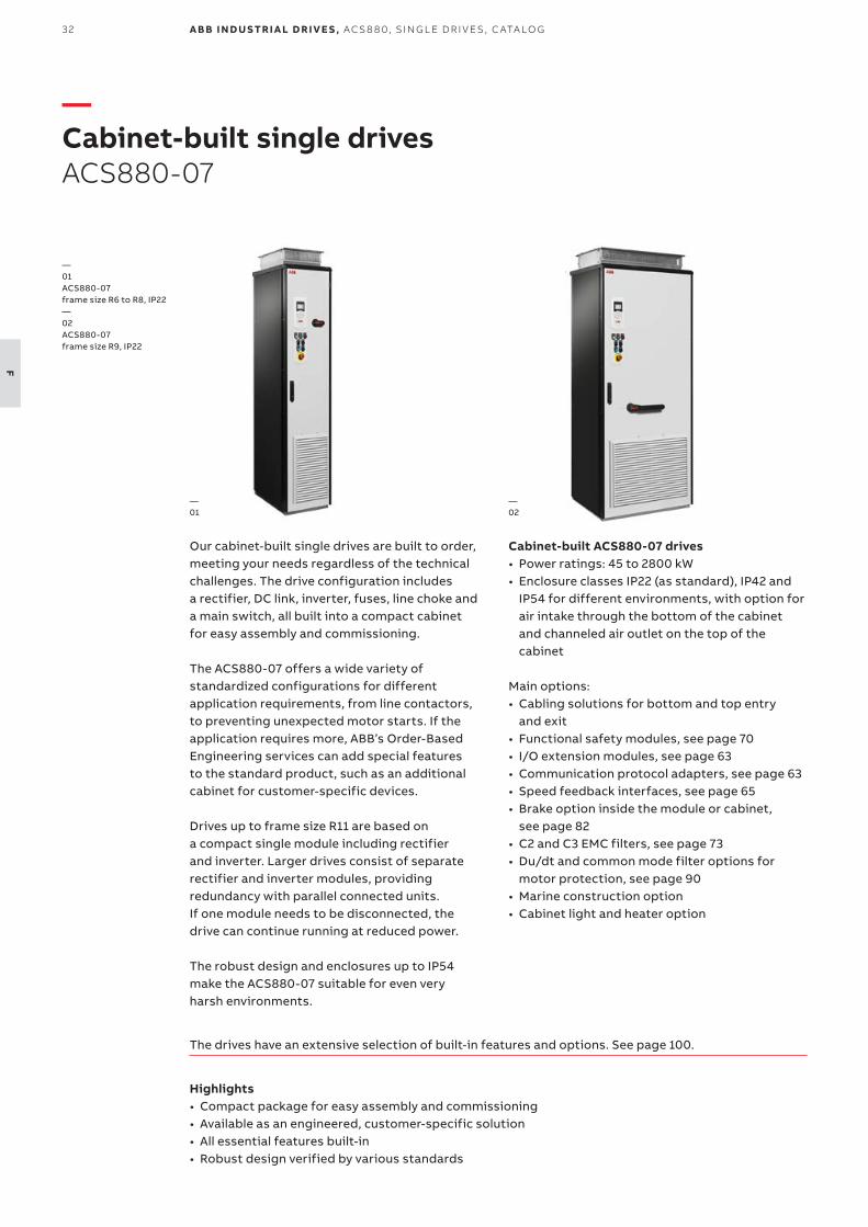
F
—Cabinet-built single drivesACS880-07
Our cabinet-built single drives are built to order, meeting your needs regardless of the technical challenges. The drive configuration includes a rectifier, DC link, inverter, fuses, line choke and a main switch, all built into a compact cabinet for easy assembly and commissioning.
The ACS880-07 offers a wide variety of standardized configurations for different application requirements, from line contactors, to preventing unexpected motor starts. If the application requires more, ABB’s Order-Based Engineering services can add special features to the standard product, such as an additional cabinet for customer-specific devices.
Drives up to frame size R11 are based on a compact single module including rectifier and inverter. Larger drives consist of separate rectifier and inverter modules, providing redundancy with parallel connected units. If one module needs to be disconnected, the drive can continue running at reduced power.
The robust design and enclosures up to IP54 make the ACS880-07 suitable for even very harsh environments.
Cabinet-built ACS880-07 drives• Power ratings: 45 to 2800 kW• Enclosure classes IP22 (as standard), IP42 and
IP54 for different environments, with option for air intake through the bottom of the cabinet and channeled air outlet on the top of the cabinet
Main options:• Cabling solutions for bottom and top entry
and exit• Functional safety modules, see page 70• I/O extension modules, see page 63• Communication protocol adapters, see page 63• Speed feedback interfaces, see page 65• Brake option inside the module or cabinet,
see page 82• C2 and C3 EMC filters, see page 73• Du/dt and common mode filter options for
motor protection, see page 90• Marine construction option• Cabinet light and heater option
Highlights• Compact package for easy assembly and commissioning• Available as an engineered, customer-specific solution• All essential features built-in• Robust design verified by various standards
The drives have an extensive selection of built-in features and options. See page 100.
—02
—01
—01 ACS880-07 frame size R6 to R8, IP22—02 ACS880-07 frame size R9, IP22
33C A B I N E T- B U I LT D R I V E S
F
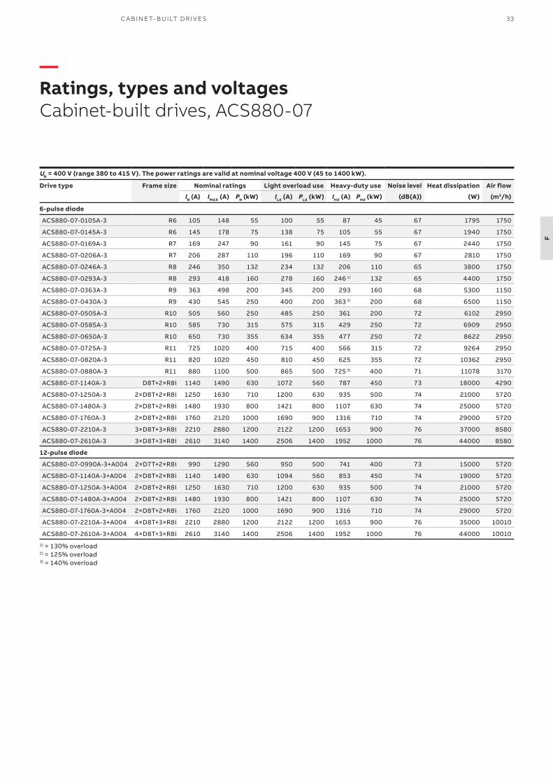
—Ratings, types and voltagesCabinet-built drives, ACS880-07
UN = 400 V (range 380 to 415 V). The power ratings are valid at nominal voltage 400 V (45 to 1400 kW).
Drive type Frame size Nominal ratings Light overload use Heavy-duty use Noise level Heat dissipation Air flow
IN (A) IMAX (A) PN (kW) ILd (A) PLd (kW) IHd (A) PHd (kW) (dB(A)) (W) (m3/h)
6-pulse diode
ACS880-07-0105A-3 R6 105 148 55 100 55 87 45 67 1795 1750
ACS880-07-0145A-3 R6 145 178 75 138 75 105 55 67 1940 1750
ACS880-07-0169A-3 R7 169 247 90 161 90 145 75 67 2440 1750
ACS880-07-0206A-3 R7 206 287 110 196 110 169 90 67 2810 1750
ACS880-07-0246A-3 R8 246 350 132 234 132 206 110 65 3800 1750
ACS880-07-0293A-3 R8 293 418 160 278 160 246 1) 132 65 4400 1750
ACS880-07-0363A-3 R9 363 498 200 345 200 293 160 68 5300 1150
ACS880-07-0430A-3 R9 430 545 250 400 200 363 2) 200 68 6500 1150
ACS880-07-0505A-3 R10 505 560 250 485 250 361 200 72 6102 2950
ACS880-07-0585A-3 R10 585 730 315 575 315 429 250 72 6909 2950
ACS880-07-0650A-3 R10 650 730 355 634 355 477 250 72 8622 2950
ACS880-07-0725A-3 R11 725 1020 400 715 400 566 315 72 9264 2950
ACS880-07-0820A-3 R11 820 1020 450 810 450 625 355 72 10362 2950
ACS880-07-0880A-3 R11 880 1100 500 865 500 725 3) 400 71 11078 3170
ACS880-07-1140A-3 D8T+2×R8i 1140 1490 630 1072 560 787 450 73 18000 4290
ACS880-07-1250A-3 2×D8T+2×R8i 1250 1630 710 1200 630 935 500 74 21000 5720
ACS880-07-1480A-3 2×D8T+2×R8i 1480 1930 800 1421 800 1107 630 74 25000 5720
ACS880-07-1760A-3 2×D8T+2×R8i 1760 2120 1000 1690 900 1316 710 74 29000 5720
ACS880-07-2210A-3 3×D8T+3×R8i 2210 2880 1200 2122 1200 1653 900 76 37000 8580
ACS880-07-2610A-3 3×D8T+3×R8i 2610 3140 1400 2506 1400 1952 1000 76 44000 8580
12-pulse diode
ACS880-07-0990A-3+A004 2×D7T+2×R8i 990 1290 560 950 500 741 400 73 15000 5720
ACS880-07-1140A-3+A004 2×D8T+2×R8i 1140 1490 630 1094 560 853 450 74 19000 5720
ACS880-07-1250A-3+A004 2×D8T+2×R8i 1250 1630 710 1200 630 935 500 74 21000 5720
ACS880-07-1480A-3+A004 2×D8T+2×R8i 1480 1930 800 1421 800 1107 630 74 25000 5720
ACS880-07-1760A-3+A004 2×D8T+2×R8i 1760 2120 1000 1690 900 1316 710 74 29000 5720
ACS880-07-2210A-3+A004 4×D8T+3×R8i 2210 2880 1200 2122 1200 1653 900 76 35000 10010
ACS880-07-2610A-3+A004 4×D8T+3×R8i 2610 3140 1400 2506 1400 1952 1000 76 44000 10010
1) = 130% overload 2) = 125% overload 3) = 140% overload
34 A B B I N D U S TR I A L D R I V E S , AC S 8 8 0, S I N G L E D R I V E S , C ATA LO G
F
UN = 500 V (range 380 to 500 V). The power ratings are valid at nominal voltage 500 V (45 to 1400 kW).
Drive type Frame size Nominal ratings Light overload use Heavy-duty use Noise level Heat dissipation Air flow
IN (A) IMAX (A) PN (kW) ILd (A) PLd (kW) IHd (A) PHd (kW) (dB(A)) (W) (m3/h)
6-pulse diode
ACS880-07-0096A-5 R6 96 148 55 91 55 77 45 67 1795 1750
ACS880-07-0124A-5 R6 124 178 75 118 75 96 55 67 1940 1750
ACS880-07-0156A-5 R7 156 247 90 148 90 124 75 67 2440 1750
ACS880-07-0180A-5 R7 180 287 110 171 110 156 90 67 2810 1750
ACS880-07-0240A-5 R8 240 350 132 228 132 180 110 65 3800 1750
ACS880-07-0260A-5 R8 260 418 160 247 160 240 1) 132 65 4400 1750
ACS880-07-0361A-5 R9 361 542 200 343 200 302 200 68 5300 1150
ACS880-07-0414A-5 R9 414 542 250 393 250 361 2) 200 68 6500 1150
ACS880-07-0460A-5 R10 460 560 315 450 315 330 200 72 4903 2950
ACS880-07-0503A-5 R10 503 560 355 483 315 361 250 72 6102 2950
ACS880-07-0583A-5 R10 583 730 400 573 400 414 250 72 6909 2950
ACS880-07-0635A-5 R10 635 730 450 623 450 477 315 72 8622 2950
ACS880-07-0715A-5 R11 715 850 500 705 500 566 400 72 9264 2950
ACS880-07-0820A-5 R11 820 1020 560 807 560 625 450 71 10362 2950
ACS880-07-0880A-5 R11 880 1100 630 857 560 697 500 71 11078 2950
ACS880-07-1070A-5 D8T+2×R8i 1070 1400 710 1027 710 800 560 73 18000 4290
ACS880-07-1320A-5 2×D8T+2×R8i 1320 1720 900 1267 900 987 710 74 22000 5720
ACS880-07-1450A-5 2xD8T+2xR8i 1450 1890 1000 1392 900 1085 710 74 25800 5720
ACS880-07-1580A-5 2×D8T+2×R8i 1580 2060 1100 1517 1000 1182 800 74 27000 5720
ACS880-07-1800A-5 2×D8T+3×R8i 1800 2340 1250 1728 1200 1346 900 75 32000 7150
ACS880-07-1980A-5 2×D8T+3×R8i 1980 2580 1400 1901 1300 1481 1000 75 36000 7150
12-pulse diode
ACS880-07-0990A-5+A004 2×D7T+2×R8i 990 1290 710 950 630 741 500 73 16000 5720
ACS880-07-1320A-5+A004 2×D8T+2×R8i 1320 1720 900 1267 900 987 710 74 22000 5720
ACS880-07-1450A-5+A004 2×D8T+2×R8i 1450 1890 1000 1392 900 1085 710 74 25000 5720
ACS880-07-1580A-5+A004 2×D8T+2×R8i 1580 2060 1100 1517 1000 1182 800 74 27000 5720
ACS880-07-1800A-5+A004 2×D8T+3×R8i 1800 2340 1250 1728 1200 1346 900 75 32000 7150
ACS880-07-1980A-5+A004 2×D8T+3×R8i 1980 2580 1400 1901 1300 1481 1000 75 36000 7150
1) =130% overload 2) = 125% overload
35C A B I N E T- B U I LT D R I V E S
F
Nominal ratings
IN Rated current available continuously without overloadability at 40 °C.
PN Typical motor power in no-overload use.
Maximum output current
Imax Maximum output current. Available for 10 seconds at start, then as long as allowed by drive temperature.
Light-overload use
ILd Continuous current allowing 110% ILd for 1 minute every 5 minutes at 40 °C.
PLd Typical motor power in light-overload use.
Heavy-duty use
IHd Continuous current allowing 150% IHd for 1 minute every 5 minutes at 40 °C.
PHd Typical motor power in heavy-duty use.
The ratings apply at 40 °C ambient temperature. At higher temperatures (up to 50 °C), the derating is 1%/1 °C.Operation above 150 Hz might require type specific derating.
UN = 690 V (range 525 to 690 V). The power ratings are valid at nominal voltage 690 V (45 to 2800 kW).
Drive type Frame size Nominal ratings Light overload use Heavy-duty use Noise level Heat dissipation Air flow
IN (A) IMAX (A) PN (kW) ILd (A) PLd (kW) IHd (A) PHd (kW) (dB(A)) (W) (m3/h)
6-pulse diode
ACS880-07-0061A-7 R6 61 104 55 58 55 49 45 67 1795 1750
ACS880-07-0084A-7 R6 84 124 75 80 75 61 55 67 1940 1750
ACS880-07-0098A-7 R7 98 168 90 93 90 84 75 67 2440 1750
ACS880-07-0119A-7 R7 119 198 110 113 110 98 90 67 2810 1750
ACS880-07-0142A-7 R8 142 250 132 135 132 119 110 65 3800 1750
ACS880-07-0174A-7 R8 174 274 160 165 160 142 132 65 4400 1750
ACS880-07-0210A-7 R9 210 384 200 200 200 174 160 68 4700 1150
ACS880-07-0271A-7 R9 271 411 250 257 250 210 200 68 5300 1150
ACS880-07-0330A-7 R10 330 480 315 320 315 255 250 72 5640 2950
ACS880-07-0370A-7 R10 370 520 355 360 355 325 315 72 6371 2950
ACS880-07-0430A-7 R10 430 520 400 420 400 360 4) 355 72 7570 2950
ACS880-07-0470A-7 R11 470 655 450 455 450 415 400 72 6611 2950
ACS880-07-0522A-7 R11 522 655 500 505 500 455 450 72 7388 2950
ACS880-07-0590A-7 R11 590 800 560 571 560 505 500 71 8971 2950
ACS880-07-0650A-7 R11 650 820 630 630 630 571 4) 560 71 9980 3170
ACS880-07-0721A-7 R11 721 820 710 705 630 571 4) 560 71 11177 3170
ACS880-07-0800A-7 D8T+2×R8i 800 1200 800 768 710 598 560 73 16000 4290
ACS880-07-0900A-7 D8T+2×R8i 900 1350 900 864 800 673 630 74 20000 4290
ACS880-07-1160A-7 2×D8T+2×R8i 1160 1740 1100 1114 1100 868 800 74 26000 5720
ACS880-07-1450A-7 2×D8T+3×R8i 1450 2180 1400 1392 1250 1085 1000 75 32000 7150
ACS880-07-1650A-7 2×D8T+3×R8i 1650 2480 1600 1584 1500 1234 1200 75 36500 7150
ACS880-07-1950A-7 3×D8T+4×R8i 1950 2930 1900 1872 1800 1459 1400 76 44000 10010
ACS880-07-2300A-7 3×D8T+4×R8i 2300 3450 2200 2208 2000 1720 1600 76 52000 10010
ACS880-07-2600A-7 4×D8T+5×R8i 2600 3900 2500 2496 2400 1945 1900 78 58000 12870
ACS880-07-2860A-7 4×D8T+5×R8i 2860 4290 2800 2746 2600 2139 2000 78 65000 12870
12-pulse diode
ACS880-07-0800A-7+A004 2×D7T+2×R8i 800 1200 800 768 710 598 560 73 16000 5720
ACS880-07-0950A-7+A004 2×D8T+2×R8i 950 1430 900 912 800 711 630 74 20000 5720
ACS880-07-1160A-7+A004 2×D8T+2×R8i 1160 1740 1100 1114 1100 868 800 74 26000 5720
ACS880-07-1450A-7+A004 2×D8T+3×R8i 1450 2180 1400 1392 1250 1085 1000 75 32000 7150
ACS880-07-1650A-7+A004 2×D8T+3×R8i 1650 2480 1600 1584 1500 1234 1200 75 36500 7150
ACS880-07-1950A-7+A004 4×D8T+4×R8i 1950 2930 1900 1872 1800 1459 1400 77 44000 11440
ACS880-07-2300A-7+A004 4×D8T+4×R8i 2300 3450 2200 2208 2000 1720 1600 77 52000 11440
ACS880-07-2600A-7+A004 4×D8T+5×R8i 2600 3900 2500 2496 2400 1945 1900 78 58000 12870
ACS880-07-2860A-7+A004 4×D8T+5×R8i 2860 4290 2800 2746 2600 2139 2000 78 65000 128704) = 144% overload

36 A B B I N D U S TR I A L D R I V E S , AC S 8 8 0, S I N G L E D R I V E S , C ATA LO G
G
—Regenerative drivesACS880-11 and ACS880-17
Energy savingsThe ACS880-11/17 regenerative drives are a compact and complete regenerative drive solution, with everything you need for regenerative operation in cyclic or continuous braking applications. Such applications include cranes, elevators, centrifuges, downhill conveyers and test benches. With regenerative functionality, the braking energy of the motor is returned to the drive and distributed to the supply network so that it can be utilized by other equipment. Compared to mechanical or resistor braking, where braking energy is wasted as heat, regenerative drive operation offers significant energy consumption and cooling savings.
The ACS880 regenerative drives achieve a unity power factor, indicating that electrical energy is being used efficiently. There’s a possibility to increase system efficiency even further with common DC solutions by sharing braking energy between multiple drives through a DC link.
—Possibility to regenerate 100% of power continuously
Minimized downtimeThe ACS880 regenerative drive offers immunity to network disturbances. The drive will not interrupt the process or affect its quality in unstable supply network conditions. The drive’s active supply unit can boost the output voltage to enable full motor voltage, even when the supply voltage is below nominal. This ensures reliable operation in weak networks. This voltage boost capability can also be utilized to overcome voltage drops caused by long supply or motor cables.
Optimized cost and spaceEverything needed for regenerative operation, such as an active supply unit and a low harmonic line filter are integrated into the drive, and no external braking devices are needed.
Advantages: • Quick, easy drive installation • Small installation footprint • No need to add cooling to handle the heat
generated by mechanical or resistor braking• Simplified wiring • Less spare parts needed
The “all inside” design helps to cut engineering and assembly time, as well as to reduce equipment costs and the risk of errors.
The drive’s voltage boost capability can be an advantage in motor dimensioning. With a higher motor voltage, the same power is achieved with less current, which improves motor efficiency and may allow a smaller motor to be used.
The drive offers a possibility for network power factor correction to compensate for the low power factors of equipment connected to the same network. It reduces the need for additional power factor correction equipment, such as filters and large capacitor banks. It can also help to avoid penalty charges from electrical utilities for poor power factors.
Maximized motor performance and efficiencyThe drive can provide full motor voltage even if the supply voltage fluctuates. Regeneration can occur for as long as necessary and as often as needed.
The drive features direct torque control (DTC) as standard, making it suitable for very demanding applications as well. DTC provides precise speed and torque control for maximum motor performance and motor efficiency.
Clean supply networkThe drive produces exceptionally low harmonic content and exceeds the requirements of harmonic guidance/standards such as IEEE 519, IEC61000-3-2, IEC61000-3-12, IEC61000-3-4 and G5/4. Compared to a conventional drive, the harmonic content is reduced by up to 97%. The total harmonic current distortion is typically <3% in a nominal situation and an undistorted network.
For more information, visit https://new.abb.com/drives/regenerativedrives.
Speed
Power+
-—01
—01 Speed and power curves in cyclic operation
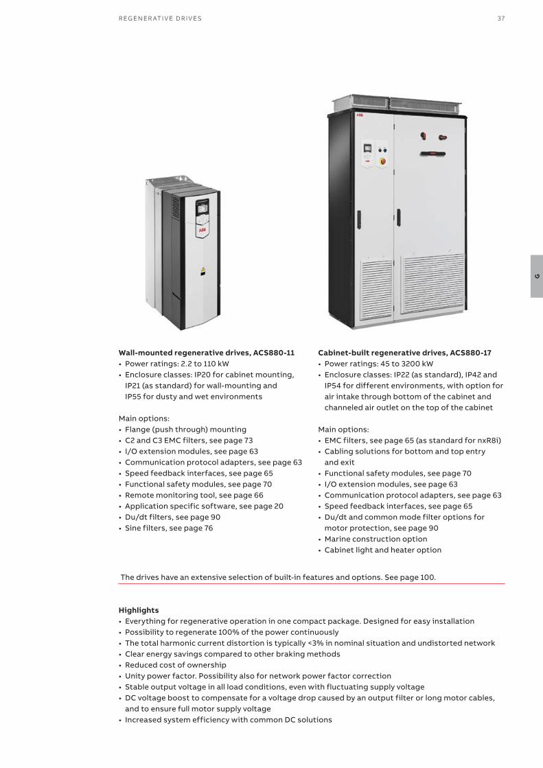
37R EG EN ER ATI V E D R I V E S
G
Wall-mounted regenerative drives, ACS880-11• Power ratings: 2.2 to 110 kW• Enclosure classes: IP20 for cabinet mounting,
IP21 (as standard) for wall-mounting and IP55 for dusty and wet environments
Main options: • Flange (push through) mounting• C2 and C3 EMC filters, see page 73• I/O extension modules, see page 63• Communication protocol adapters, see page 63• Speed feedback interfaces, see page 65• Functional safety modules, see page 70• Remote monitoring tool, see page 66• Application specific software, see page 20• Du/dt filters, see page 90• Sine filters, see page 76
Cabinet-built regenerative drives, ACS880-17• Power ratings: 45 to 3200 kW• Enclosure classes: IP22 (as standard), IP42 and
IP54 for different environments, with option for air intake through bottom of the cabinet and channeled air outlet on the top of the cabinet
Main options: • EMC filters, see page 65 (as standard for nxR8i)• Cabling solutions for bottom and top entry
and exit• Functional safety modules, see page 70• I/O extension modules, see page 63• Communication protocol adapters, see page 63• Speed feedback interfaces, see page 65• Du/dt and common mode filter options for
motor protection, see page 90• Marine construction option• Cabinet light and heater option
Highlights• Everything for regenerative operation in one compact package. Designed for easy installation• Possibility to regenerate 100% of the power continuously• The total harmonic current distortion is typically <3% in nominal situation and undistorted network• Clear energy savings compared to other braking methods• Reduced cost of ownership• Unity power factor. Possibility also for network power factor correction• Stable output voltage in all load conditions, even with fluctuating supply voltage• DC voltage boost to compensate for a voltage drop caused by an output filter or long motor cables,
and to ensure full motor supply voltage• Increased system efficiency with common DC solutions
The drives have an extensive selection of built-in features and options. See page 100.

38 A B B I N D U S TR I A L D R I V E S , AC S 8 8 0, S I N G L E D R I V E S , C ATA LO G
G

39R EG EN ER ATI V E D R I V E S
G
—Ratings, types and voltagesWall-mounted regenerative drives, ACS880-11
Nominal ratings
IN Rated current available continuously without overloadability at 40 °C.
PN Typical motor power in no-overload use.
Maximum output current
Imax Maximum output current. Available for 10 seconds at start, then as long as allowed by drive temperature.
Light-overload use
ILd Continuous current allowing 110% ILd for 1 minute every 5 minutes at 40 °C.
PLd Typical motor power in light-overload use.
Heavy-duty use
IHd Continuous current allowing 150% IHd for 1 minute every 5 minutes at 40 °C.
PHd Typical motor power in heavy-duty use.
The ratings apply at 40 °C ambient temperature. At higher temperatures (up to 55 °C) the derating is 1%/1 °C.
UN = 400 V (range 380 to 415 V). The power ratings are valid at nominal voltage 400 V (3 to 110 kW).
Drive type Frame size Nominal ratings Light overload use Heavy-duty use Noise level
Heat dissipation
Air flow
IN (A) IMAX (A) PN (kW) ILd (A) PLd (kW) IHd (A) PHd (kW) (dB(A)) (W) (m3/h)
ACS880-11-09A4-3 R3 10 13.6 4 9.5 4 8 3 57 226 361
ACS880-11-12A6-3 R3 12.9 17 5.5 12 5.5 10 4 57 329 361
ACS880-11-017A-3 R3 17 21.9 7.5 16 7.5 12.9 5.4 57 395 361
ACS880-11-025A-3 R3 25 28.8 11 24 11 17 7.5 57 579 361
ACS880-11-032A-3 R6 32 42.5 15 30 15 25 11 71 625 550
ACS880-11-038A-3 R6 38 54.4 18.5 36 18.5 32 15 71 751 550
ACS880-11-045A-3 R6 45 64.6 22 43 22 38 18.5 71 912 550
ACS880-11-061A-3 R6 61 76.5 30 58 30 45 22 71 1088 550
ACS880-11-072A-3 R6 72 103.7 37 68 37 61 30 71 1502 550
ACS880-11-087A-3 R6 87 122.4 45 83 45 72 37 71 1904 550
ACS880-11-105A-3 R8 105 148 55 100 55 87 45 68 1877 860
ACS880-11-145A-3 R8 145 178 75 138 75 105 55 68 2963 860
ACS880-11-169A-3 R8 169 247 90 161 90 145 75 68 3168 860
ACS880-11-206A-3 R8 206 287 110 196 110 169 90 68 3990 860
UN = 500 V (range 380 to 500 V). The power ratings are valid at nominal voltage 500 V (2.2 to 110 kW).
Drive type Frame size Nominal ratings Light overload use Heavy-duty use Noise level
Heat dissipation
Air flow
IN (A) IMAX (A) PN (kW) ILd (A) PLd (kW) IHd (A) PHd (kW) (dB(A)) (W) (m3/h)
ACS880-11-07A6-5 R3 7.6 9.5 4 7.2 4 5.2 2.2 57 219 361
ACS880-11-11A0-5 R3 11 13.8 5.5 10.4 5.5 7.6 4 57 278 361
ACS880-11-014A-5 R3 14 18.7 7.5 13 7.5 11 5.5 57 321 361
ACS880-11-021A-5 R3 21 26.3 11 19 11 14 7.5 57 473 361
ACS880-11-027A-5 R6 27 35.7 15 26 15 21 11 71 625 550
ACS880-11-034A-5 R6 34 45.9 18.5 32 18.5 27 15 71 711 550
ACS880-11-040A-5 R6 40 57.8 22 38 22 34 18.5 71 807 550
ACS880-11-052A-5 R6 52 68 30 49 30 40 22 71 960 550
ACS880-11-065A-5 R6 65 88.4 37 62 37 52 30 71 1223 550
ACS880-11-077A-5 R6 77 110.5 45 73 45 65 37 71 1560 550
ACS880-11-101A-5 R8 101 148 55 91 55 77 45 68 1995 860
ACS880-11-124A-5 R8 124 178 75 118 75 96 55 68 2800 860
ACS880-11-156A-5 R8 156 247 90 148 90 124 75 68 3168 860
ACS880-11-180A-5 R8 180 287 110 171 110 156 90 68 3872 860
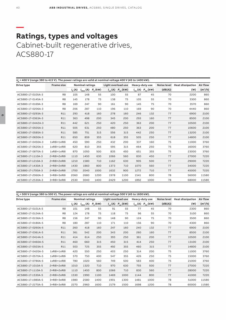
40 A B B I N D U S TR I A L D R I V E S , AC S 8 8 0, S I N G L E D R I V E S , C ATA LO G
G
—Ratings, types and voltagesCabinet-built regenerative drives, ACS880-17
UN = 400 V (range 380 to 415 V). The power ratings are valid at nominal voltage 400 V (45 to 1400 kW).
Drive type Frame size Nominal ratings Light overload use Heavy-duty use Noise level Heat dissipation Air flow
IN (A) IMAX (A) PN (kW) ILd (A) PLd (kW) IHd (A) PHd (kW) (dB(A)) (W) (m3/h)
ACS880-17-0105A-3 R8 105 148 55 100 55 87 45 70 2200 860
ACS880-17-0145A-3 R8 145 178 75 138 75 105 55 70 3300 860
ACS880-17-0169A-3 R8 169 247 90 161 90 145 75 70 3570 860
ACS880-17-0206A-3 R8 206 287 110 196 110 169 90 70 4440 860
ACS880-17-0293A-3 R11 293 418 160 278 160 246 132 77 6900 2100
ACS880-17-0363A-3 R11 363 498 200 345 200 293 160 77 8500 2100
ACS880-17-0442A-3 R11 442 621 250 420 250 363 200 77 10500 2100
ACS880-17-0505A-3 R11 505 631 250 480 250 363 200 77 10600 2100
ACS880-17-0585A-3 R11 585 751 315 556 315 442 250 77 13200 2100
ACS880-17-0650A-3 R11 650 859 355 618 355 505 250 77 14800 2100
ACS880-17-0450A-3 1xR8i+1xR8i 450 590 250 432 200 337 160 75 11000 3760
ACS880-17-0620A-3 1xR8i+1xR8i 620 810 355 595 315 464 250 75 16000 3760
ACS880-17-0870A-3 1xR8i+1xR8i 870 1050 500 835 450 651 355 75 23000 3760
ACS880-17-1110A-3 2×R8i+2xR8i 1110 1450 630 1066 560 830 450 77 27000 7220
ACS880-17-1210A-3 2×R8i+2xR8i 1210 1580 710 1162 630 905 500 77 29000 7220
ACS880-17-1430A-3 2×R8i+2xR8i 1430 1860 800 1373 710 1070 560 77 34000 7220
ACS880-17-1700A-3 2×R8i+2xR8i 1700 2040 1000 1632 900 1272 710 77 45000 7220
ACS880-17-2060A-3 3×R8i+3xR8i 2060 2680 1200 1978 1100 1541 800 78 56000 11580
ACS880-17-2530A-3 3×R8i+3xR8i 2530 3040 1400 2429 1200 1892 1000 78 68000 11580
UN = 500 V (range 380 to 500 V). The power ratings are valid at nominal voltage 500 V (45 to 1600 kW).
Drive type Frame size Nominal ratings Light overload use Heavy-duty use Noise level Heat dissipation Air flow
IN (A) IMAX (A) PN (kW) ILd (A) PLd (kW) IHd (A) PHd (kW) (dB(A)) (W) (m3/h)
ACS880-17-0101A-5 R8 101 148 55 91 55 77 45 70 2300 860
ACS880-17-0124A-5 R8 124 178 75 118 75 96 55 70 3100 860
ACS880-17-0156A-5 R8 156 247 90 148 90 124 75 70 3500 860
ACS880-17-0180A-5 R8 180 287 110 171 110 156 90 70 4300 860
ACS880-17-0260A-5 R11 260 418 160 247 160 240 132 77 6900 2100
ACS880-17-0361A-5 R11 361 542 200 343 200 260 160 77 8500 2100
ACS880-17-0414A-5 R11 414 614 250 393 250 361 200 77 10500 2100
ACS880-17-0460A-5 R11 460 660 315 450 315 414 250 77 13100 2100
ACS880-17-0503A-5 R11 503 725 355 492 355 460 315 77 14800 2100
ACS880-17-0420A-5 1xR8i+1xR8i 420 550 250 403 250 314 200 75 11000 3760
ACS880-17-0570A-5 1xR8i+1xR8i 570 750 400 547 355 426 250 75 15000 3760
ACS880-17-0780A-5 1xR8i+1xR8i 780 1020 560 749 500 583 400 75 21000 3760
ACS880-17-1010A-5 2×R8i+2xR8i 1010 1320 710 970 630 755 500 77 27000 7220
ACS880-17-1110A-5 2×R8i+2xR8i 1110 1450 800 1066 710 830 560 77 28000 7220
ACS880-17-1530A-5 2×R8i+2xR8i 1530 1990 1100 1469 1000 1144 800 77 41000 7220
ACS880-17-1980A-5 3×R8i+3xR8i 1980 2580 1400 1901 1300 1481 1000 78 51000 11580
ACS880-17-2270A-5 3×R8i+3xR8i 2270 2960 1600 2179 1500 1698 1200 78 60000 11580
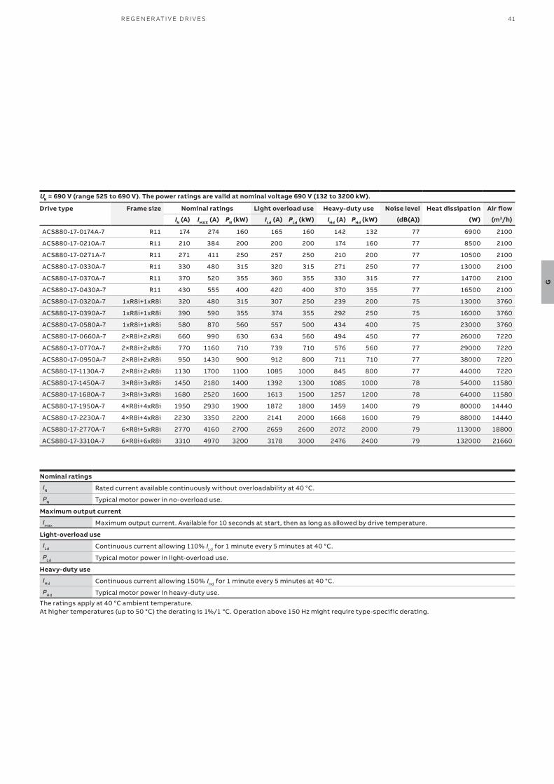
41R EG EN ER ATI V E D R I V E S
G
Nominal ratings
IN Rated current available continuously without overloadability at 40 °C.
PN Typical motor power in no-overload use.
Maximum output current
Imax Maximum output current. Available for 10 seconds at start, then as long as allowed by drive temperature.
Light-overload use
ILd Continuous current allowing 110% ILd for 1 minute every 5 minutes at 40 °C.
PLd Typical motor power in light-overload use.
Heavy-duty use
IHd Continuous current allowing 150% IHd for 1 minute every 5 minutes at 40 °C.
PHd Typical motor power in heavy-duty use.
The ratings apply at 40 °C ambient temperature. At higher temperatures (up to 50 °C) the derating is 1%/1 °C. Operation above 150 Hz might require type-specific derating.
UN = 690 V (range 525 to 690 V). The power ratings are valid at nominal voltage 690 V (132 to 3200 kW).
Drive type Frame size Nominal ratings Light overload use Heavy-duty use Noise level Heat dissipation Air flow
IN (A) IMAX (A) PN (kW) ILd (A) PLd (kW) IHd (A) PHd (kW) (dB(A)) (W) (m3/h)
ACS880-17-0174A-7 R11 174 274 160 165 160 142 132 77 6900 2100
ACS880-17-0210A-7 R11 210 384 200 200 200 174 160 77 8500 2100
ACS880-17-0271A-7 R11 271 411 250 257 250 210 200 77 10500 2100
ACS880-17-0330A-7 R11 330 480 315 320 315 271 250 77 13000 2100
ACS880-17-0370A-7 R11 370 520 355 360 355 330 315 77 14700 2100
ACS880-17-0430A-7 R11 430 555 400 420 400 370 355 77 16500 2100
ACS880-17-0320A-7 1xR8i+1xR8i 320 480 315 307 250 239 200 75 13000 3760
ACS880-17-0390A-7 1xR8i+1xR8i 390 590 355 374 355 292 250 75 16000 3760
ACS880-17-0580A-7 1xR8i+1xR8i 580 870 560 557 500 434 400 75 23000 3760
ACS880-17-0660A-7 2×R8i+2xR8i 660 990 630 634 560 494 450 77 26000 7220
ACS880-17-0770A-7 2×R8i+2xR8i 770 1160 710 739 710 576 560 77 29000 7220
ACS880-17-0950A-7 2×R8i+2xR8i 950 1430 900 912 800 711 710 77 38000 7220
ACS880-17-1130A-7 2×R8i+2xR8i 1130 1700 1100 1085 1000 845 800 77 44000 7220
ACS880-17-1450A-7 3×R8i+3xR8i 1450 2180 1400 1392 1300 1085 1000 78 54000 11580
ACS880-17-1680A-7 3×R8i+3xR8i 1680 2520 1600 1613 1500 1257 1200 78 64000 11580
ACS880-17-1950A-7 4×R8i+4xR8i 1950 2930 1900 1872 1800 1459 1400 79 80000 14440
ACS880-17-2230A-7 4×R8i+4xR8i 2230 3350 2200 2141 2000 1668 1600 79 88000 14440
ACS880-17-2770A-7 6×R8i+5xR8i 2770 4160 2700 2659 2600 2072 2000 79 113000 18800
ACS880-17-3310A-7 6×R8i+6xR8i 3310 4970 3200 3178 3000 2476 2400 79 132000 21660
42 A B B I N D U S TR I A L D R I V E S , AC S 8 8 0, S I N G L E D R I V E S , C ATA LO G
H
—Ultra-low harmonic drivesACS880-31 and ACS880-37
Harmonic distortions can disturb or even damage sensitive equipment connected in the same environment. Harmonics also cause additional losses in the network.
Clean supply networkThe drive produces exceptionally low harmonic content and exceeds the requirements of harmonic guidance/standards such as IEEE 519, IEC61000-3-2, IEC61000-3-12, IEC61000-3-4 and G5/4. Compared to a conventional drive, the harmonic content is reduced by up to 97%. The total harmonic current distortion is typically <3% in a nominal situation and an undistorted network. A common DC solution introduces a cost-efficient way of keeping the supply network clean in an installation of multiple drives.
—Keeps the network clean
Minimized downtimeThe ACS880 ultra-low harmonic drive offers immunity to network disturbances. The drive will not interrupt the process or affect its quality in unstable supply network conditions. The drive’s active supply unit can boost the output voltage to enable full motor voltage, even when the supply voltage is below nominal. This ensures reliable operation in weak networks. This voltage boost capability can also be utilized to overcome voltage drops caused by long supply or motor cables. The possibility to stabilize the output voltage of the drive is an advantage compared to alternative low harmonic solutions where voltage cannot be boosted.
Optimized cost and spaceThe compact drive features built-in harmonics mitigation. This includes an active supply unit and
Harmonic content reduction
up to
97%
Harmonic distortion typically
3%
a low harmonic line filter. As there is no need for external filters, multi-pulse arrangements or special transformers, the simple installation offers significant space, time and cost savings.
As there is less risk of overheating with lower harmonic currents, there is no need to over-dimension equipment such as transformers and cables. The drive’s voltage boost capability can be an advantage in motor dimensioning. With a higher motor voltage, the same power is achieved with a lower current, which improves motor efficiency and may allow a smaller motor to be used.
Maximized motor performance and efficiencyThe drive can provide full motor voltage even if the supply voltage fluctuates. It features direct torque control (DTC) as standard, making it suitable for very demanding applications as well. DTC provides precise speed and torque control for maximum motor performance and motor efficiency.
—Reduces the total cost of ownership
Efficient energy utilizationThe ACS880 ultra-low harmonic drives achieve a unity power factor, indicating that electrical energy is being used efficiently.
The drive offers the possibility for network power factor correction to compensate for the low power factors of equipment connected to the same network. It can help to avoid penalty charges set by electrical utilities for poor power factors.
Lower harmonics and full motor voltage at all times mean reduced system losses and better overall system efficiency.
For more information, visit http://new.abb.com/drives/harmonics.
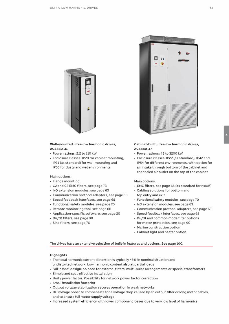
43U LTR A - LOW H A R M O N I C D R I V E S
H
Highlights• The total harmonic current distortion is typically <3% in nominal situation and
undistorted network. Low harmonic content also at partial loads• “All inside” design: no need for external filters, multi-pulse arrangements or special transformers• Simple and cost-effective installation• Unity power factor. Possibility for network power factor correction• Small installation footprint• Output voltage stabilization secures operation in weak networks• DC voltage boost to compensate for a voltage drop caused by an output filter or long motor cables,
and to ensure full motor supply voltage• Increased system efficiency with lower component losses due to very low level of harmonics
The drives have an extensive selection of built-in features and options. See page 100.
Wall-mounted ultra-low harmonic drives, ACS880-31• Power ratings: 2.2 to 110 kW• Enclosure classes: IP20 for cabinet mounting,
IP21 (as standard) for wall-mounting and IP55 for dusty and wet environments
Main options: • Flange mounting• C2 and C3 EMC filters, see page 73• I/O extension modules, see page 63• Communication protocol adapters, see page 58• Speed feedback interfaces, see page 65• Functional safety modules, see page 70• Remote monitoring tool, see page 66• Application-specific software, see page 20• Du/dt filters, see page 90• Sine filters, see page 76
Cabinet-built ultra-low harmonic drives, ACS880-37• Power ratings: 45 to 3200 kW• Enclosure classes: IP22 (as standard), IP42 and
IP54 for different environments, with option for air intake through bottom of the cabinet and channeled air outlet on the top of the cabinet
Main options: • EMC filters, see page 65 (as standard for nxR8i)• Cabling solutions for bottom and
top entry and exit• Functional safety modules, see page 70• I/O extension modules, see page 63• Communication protocol adapters, see page 63• Speed feedback interfaces, see page 65• Du/dt and common mode filter options
for motor protection, see page 90• Marine construction option• Cabinet light and heater option
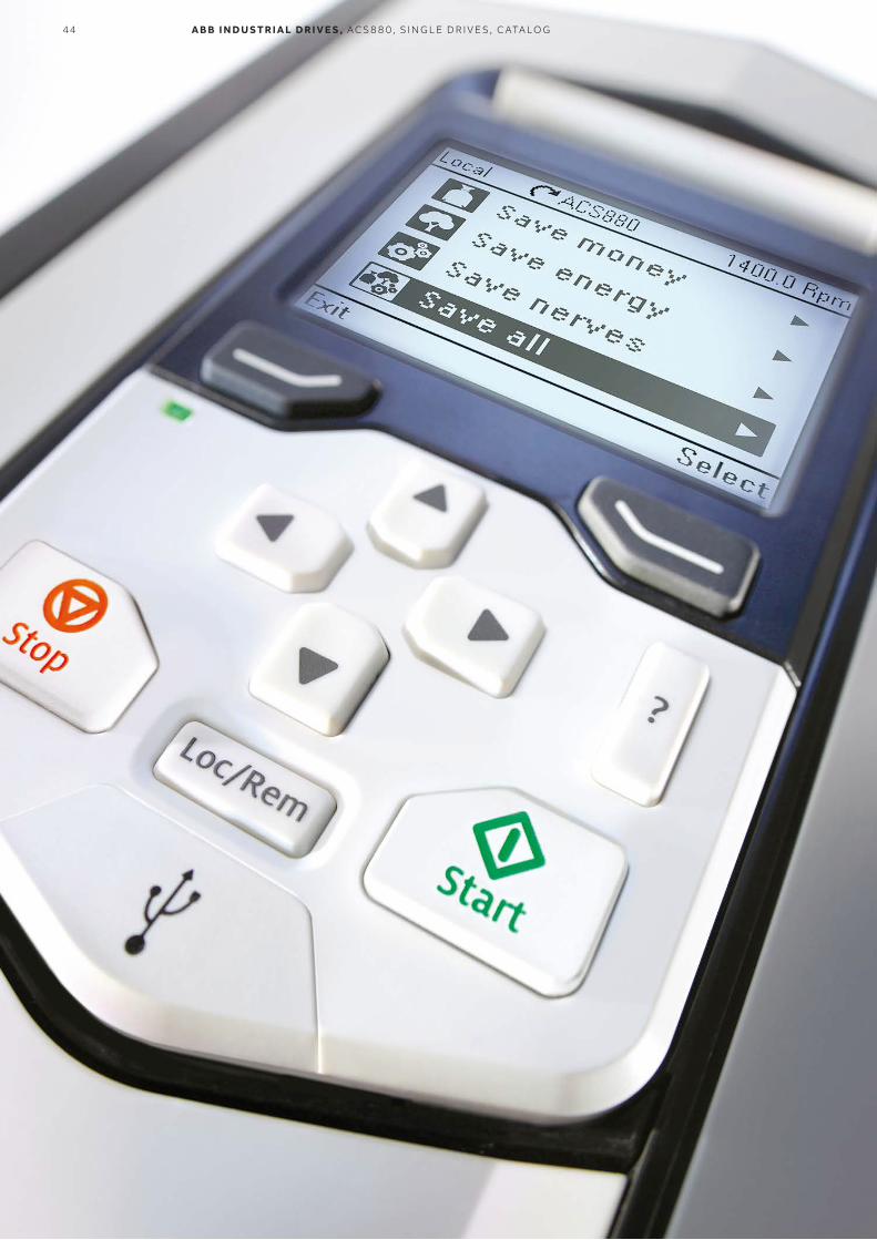
44 A B B I N D U S TR I A L D R I V E S , AC S 8 8 0, S I N G L E D R I V E S , C ATA LO G
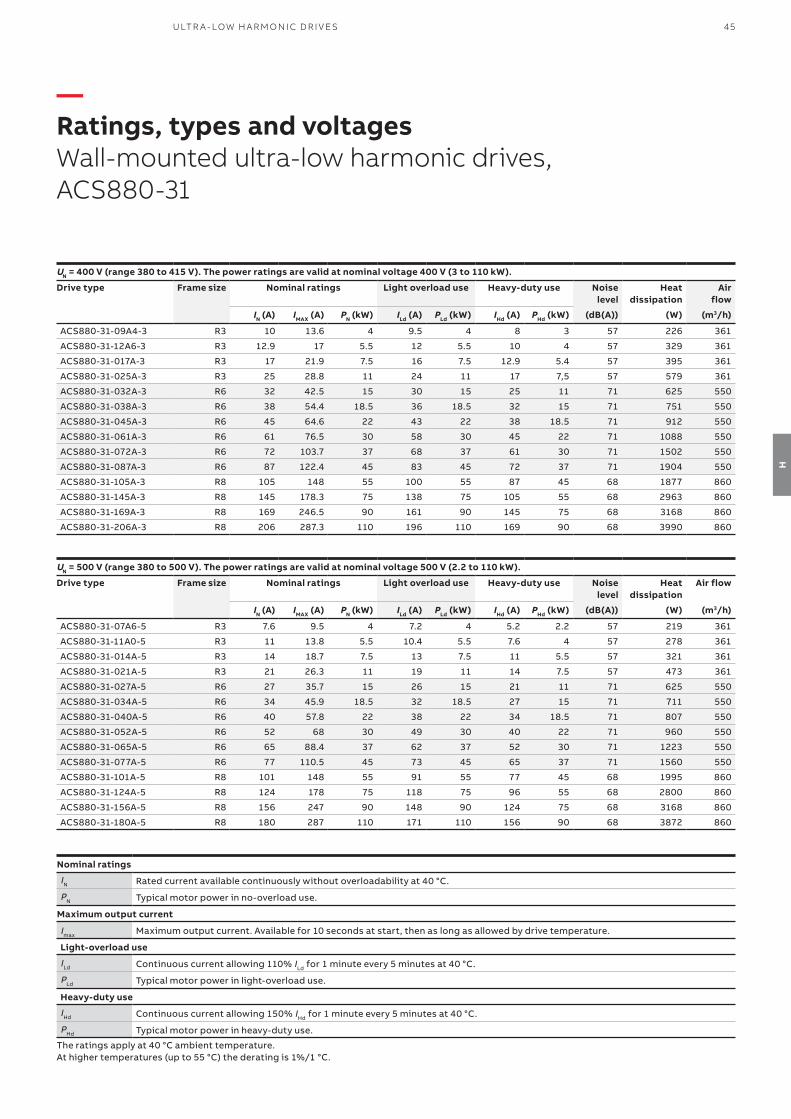
45U LTR A - LOW H A R M O N I C D R I V E S
H
—Ratings, types and voltagesWall-mounted ultra-low harmonic drives, ACS880-31
Nominal ratings
IN Rated current available continuously without overloadability at 40 °C.
PN Typical motor power in no-overload use.
Maximum output current
Imax Maximum output current. Available for 10 seconds at start, then as long as allowed by drive temperature.
Light-overload use
ILd Continuous current allowing 110% ILd for 1 minute every 5 minutes at 40 °C.
PLd Typical motor power in light-overload use.
Heavy-duty use
IHd Continuous current allowing 150% IHd for 1 minute every 5 minutes at 40 °C.
PHd Typical motor power in heavy-duty use.
The ratings apply at 40 °C ambient temperature. At higher temperatures (up to 55 °C) the derating is 1%/1 °C.
UN = 400 V (range 380 to 415 V). The power ratings are valid at nominal voltage 400 V (3 to 110 kW).
Drive type Frame size Nominal ratings Light overload use Heavy-duty use Noise level
Heat dissipation
Air flow
IN (A) IMAX (A) PN (kW) ILd (A) PLd (kW) IHd (A) PHd (kW) (dB(A)) (W) (m3/h)
ACS880-31-09A4-3 R3 10 13.6 4 9.5 4 8 3 57 226 361
ACS880-31-12A6-3 R3 12.9 17 5.5 12 5.5 10 4 57 329 361
ACS880-31-017A-3 R3 17 21.9 7.5 16 7.5 12.9 5.4 57 395 361
ACS880-31-025A-3 R3 25 28.8 11 24 11 17 7,5 57 579 361
ACS880-31-032A-3 R6 32 42.5 15 30 15 25 11 71 625 550
ACS880-31-038A-3 R6 38 54.4 18.5 36 18.5 32 15 71 751 550
ACS880-31-045A-3 R6 45 64.6 22 43 22 38 18.5 71 912 550
ACS880-31-061A-3 R6 61 76.5 30 58 30 45 22 71 1088 550
ACS880-31-072A-3 R6 72 103.7 37 68 37 61 30 71 1502 550
ACS880-31-087A-3 R6 87 122.4 45 83 45 72 37 71 1904 550
ACS880-31-105A-3 R8 105 148 55 100 55 87 45 68 1877 860
ACS880-31-145A-3 R8 145 178.3 75 138 75 105 55 68 2963 860
ACS880-31-169A-3 R8 169 246.5 90 161 90 145 75 68 3168 860
ACS880-31-206A-3 R8 206 287.3 110 196 110 169 90 68 3990 860
UN = 500 V (range 380 to 500 V). The power ratings are valid at nominal voltage 500 V (2.2 to 110 kW).
Drive type Frame size Nominal ratings Light overload use Heavy-duty use Noise level
Heat dissipation
Air flow
IN (A) IMAX (A) PN (kW) ILd (A) PLd (kW) IHd (A) PHd (kW) (dB(A)) (W) (m3/h)
ACS880-31-07A6-5 R3 7.6 9.5 4 7.2 4 5.2 2.2 57 219 361
ACS880-31-11A0-5 R3 11 13.8 5.5 10.4 5.5 7.6 4 57 278 361
ACS880-31-014A-5 R3 14 18.7 7.5 13 7.5 11 5.5 57 321 361
ACS880-31-021A-5 R3 21 26.3 11 19 11 14 7.5 57 473 361
ACS880-31-027A-5 R6 27 35.7 15 26 15 21 11 71 625 550
ACS880-31-034A-5 R6 34 45.9 18.5 32 18.5 27 15 71 711 550
ACS880-31-040A-5 R6 40 57.8 22 38 22 34 18.5 71 807 550
ACS880-31-052A-5 R6 52 68 30 49 30 40 22 71 960 550
ACS880-31-065A-5 R6 65 88.4 37 62 37 52 30 71 1223 550
ACS880-31-077A-5 R6 77 110.5 45 73 45 65 37 71 1560 550
ACS880-31-101A-5 R8 101 148 55 91 55 77 45 68 1995 860
ACS880-31-124A-5 R8 124 178 75 118 75 96 55 68 2800 860
ACS880-31-156A-5 R8 156 247 90 148 90 124 75 68 3168 860
ACS880-31-180A-5 R8 180 287 110 171 110 156 90 68 3872 860

46 A B B I N D U S TR I A L D R I V E S , AC S 8 8 0, S I N G L E D R I V E S , C ATA LO G
H
—Ratings, types and voltagesCabinet-built ultra-low harmonic drives, ACS880-37
UN = 400 V (range 380 to 415 V). The power ratings are valid at nominal voltage 400 V (45 to 1400 kW).
Drive type Frame size Nominal ratings Light overload use Heavy-duty use Noise level Heat dissipation Air flow
IN (A) IMAX (A) PN (kW) ILd (A) PLd (kW) IHd (A) PHd (kW) (dB(A)) (W) (m3/h)
ACS880-37-0105A-3 R8 105 148 55 100 55 87 45 70 2200 860
ACS880-37-0145A-3 R8 145 178 75 138 75 105 55 70 3300 860
ACS880-37-0169A-3 R8 169 247 90 161 90 145 75 70 3570 860
ACS880-37-0206A-3 R8 206 287 110 196 110 169 90 70 4440 860
ACS880-37-0293A-3 R11 293 418 160 278 160 246 132 77 6900 2100
ACS880-37-0363A-3 R11 363 498 200 345 200 293 160 77 8500 2100
ACS880-37-0442A-3 R11 442 621 250 420 250 363 200 77 10500 2100
ACS880-37-0505A-3 R11 505 631 250 480 250 363 200 77 10600 2100
ACS880-37-0585A-3 R11 585 751 315 556 315 442 250 77 13200 2100
ACS880-37-0650A-3 R11 650 859 355 618 355 505 250 77 14800 2100
ACS880-37-0450A-3 1xR8i+1xR8i 450 590 250 432 200 337 160 75 11000 3760
ACS880-37-0620A-3 1xR8i+1xR8i 620 810 355 595 315 464 250 75 16000 3760
ACS880-37-0870A-3 1xR8i+1xR8i 870 1050 500 835 450 651 355 75 23000 3760
ACS880-37-1110A-3 2×R8i+2xR8i 1110 1450 630 1066 560 830 450 77 27000 7220
ACS880-37-1210A-3 2×R8i+2xR8i 1210 1580 710 1162 630 905 500 77 29000 7220
ACS880-37-1430A-3 2×R8i+2xR8i 1430 1860 800 1373 710 1070 560 77 34000 7220
ACS880-37-1700A-3 2×R8i+2xR8i 1700 2040 1000 1632 900 1272 710 77 45000 7220
ACS880-37-2060A-3 3×R8i+3xR8i 2060 2680 1200 1978 1100 1541 800 78 56000 11580
ACS880-37-2530A-3 3×R8i+3xR8i 2530 3040 1400 2429 1200 1892 1000 78 68000 11580
UN = 500 V (range 380 to 500 V). The power ratings are valid at nominal voltage 500 V (45 to 1600 kW).
Drive type Frame size Nominal ratings Light overload use Heavy-duty use Noise level Heat dissipation Air flow
IN (A) IMAX (A) PN (kW) ILd (A) PLd (kW) IHd (A) PHd (kW) (dB(A)) (W) (m3/h)
ACS880-37-0101A-5 R8 101 148 55 91 55 77 45 70 2300 860
ACS880-37-0124A-5 R8 124 178 75 118 75 96 55 70 3100 860
ACS880-37-0156A-5 R8 156 247 90 148 90 124 75 70 3500 860
ACS880-37-0180A-5 R8 180 287 110 171 110 156 90 70 4300 860
ACS880-37-0260A-5 R11 260 418 160 247 160 240 132 77 6900 2100
ACS880-37-0361A-5 R11 361 542 200 343 200 260 160 77 8500 2100
ACS880-37-0414A-5 R11 414 614 250 393 250 361 200 77 10500 2100
ACS880-37-0460A-5 R11 460 660 315 450 315 414 250 77 13100 2100
ACS880-37-0503A-5 R11 503 725 355 492 355 460 315 77 14800 2100
ACS880-37-0420A-5 1xR8i+1xR8i 420 550 250 403 250 314 200 75 11000 3760
ACS880-37-0570A-5 1xR8i+1xR8i 570 750 400 547 355 426 250 75 15000 3760
ACS880-37-0780A-5 1xR8i+1xR8i 780 1020 560 749 500 583 400 75 21000 3760
ACS880-37-1010A-5 2×R8i+2xR8i 1010 1320 710 970 630 755 500 77 27000 7220
ACS880-37-1110A-5 2×R8i+2xR8i 1110 1450 800 1066 710 830 560 77 28000 7220
ACS880-37-1530A-5 2×R8i+2xR8i 1530 1990 1100 1469 1000 1144 800 77 41000 7220
ACS880-37-1980A-5 3×R8i+3xR8i 1980 2580 1400 1901 1300 1481 1000 78 51000 11580
ACS880-37-2270A-5 3×R8i+3xR8i 2270 2960 1600 2179 1500 1698 1200 78 60000 11580
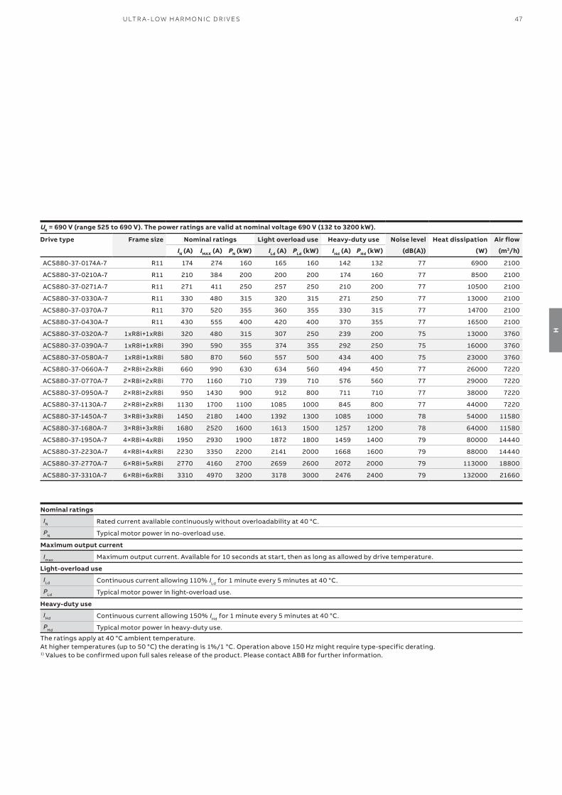
47U LTR A - LOW H A R M O N I C D R I V E S
H
UN = 690 V (range 525 to 690 V). The power ratings are valid at nominal voltage 690 V (132 to 3200 kW).
Drive type Frame size Nominal ratings Light overload use Heavy-duty use Noise level Heat dissipation Air flow
IN (A) IMAX (A) PN (kW) ILd (A) PLd (kW) IHd (A) PHd (kW) (dB(A)) (W) (m3/h)
ACS880-37-0174A-7 R11 174 274 160 165 160 142 132 77 6900 2100
ACS880-37-0210A-7 R11 210 384 200 200 200 174 160 77 8500 2100
ACS880-37-0271A-7 R11 271 411 250 257 250 210 200 77 10500 2100
ACS880-37-0330A-7 R11 330 480 315 320 315 271 250 77 13000 2100
ACS880-37-0370A-7 R11 370 520 355 360 355 330 315 77 14700 2100
ACS880-37-0430A-7 R11 430 555 400 420 400 370 355 77 16500 2100
ACS880-37-0320A-7 1xR8i+1xR8i 320 480 315 307 250 239 200 75 13000 3760
ACS880-37-0390A-7 1xR8i+1xR8i 390 590 355 374 355 292 250 75 16000 3760
ACS880-37-0580A-7 1xR8i+1xR8i 580 870 560 557 500 434 400 75 23000 3760
ACS880-37-0660A-7 2×R8i+2xR8i 660 990 630 634 560 494 450 77 26000 7220
ACS880-37-0770A-7 2×R8i+2xR8i 770 1160 710 739 710 576 560 77 29000 7220
ACS880-37-0950A-7 2×R8i+2xR8i 950 1430 900 912 800 711 710 77 38000 7220
ACS880-37-1130A-7 2×R8i+2xR8i 1130 1700 1100 1085 1000 845 800 77 44000 7220
ACS880-37-1450A-7 3×R8i+3xR8i 1450 2180 1400 1392 1300 1085 1000 78 54000 11580
ACS880-37-1680A-7 3×R8i+3xR8i 1680 2520 1600 1613 1500 1257 1200 78 64000 11580
ACS880-37-1950A-7 4×R8i+4xR8i 1950 2930 1900 1872 1800 1459 1400 79 80000 14440
ACS880-37-2230A-7 4×R8i+4xR8i 2230 3350 2200 2141 2000 1668 1600 79 88000 14440
ACS880-37-2770A-7 6×R8i+5xR8i 2770 4160 2700 2659 2600 2072 2000 79 113000 18800
ACS880-37-3310A-7 6×R8i+6xR8i 3310 4970 3200 3178 3000 2476 2400 79 132000 21660
Nominal ratings
IN Rated current available continuously without overloadability at 40 °C.
PN Typical motor power in no-overload use.
Maximum output current
Imax Maximum output current. Available for 10 seconds at start, then as long as allowed by drive temperature.
Light-overload use
ILd Continuous current allowing 110% ILd for 1 minute every 5 minutes at 40 °C.
PLd Typical motor power in light-overload use.
Heavy-duty use
IHd Continuous current allowing 150% IHd for 1 minute every 5 minutes at 40 °C.
PHd Typical motor power in heavy-duty use.
The ratings apply at 40 °C ambient temperature. At higher temperatures (up to 50 °C) the derating is 1%/1 °C. Operation above 150 Hz might require type-specific derating.1) Values to be confirmed upon full sales release of the product. Please contact ABB for further information.
48 A B B I N D U S TR I A L D R I V E S , AC S 8 8 0, S I N G L E D R I V E S , C ATA LO G
I
—Liquid-cooled drivesACS880-07LC, ACS880-07CLC, ACS880-17LC, ACS880-37LC
The compact and robust liquid-cooled cabinet drives are an ultimate solution for various applications where space savings, silent operation or durability in harsh environments is a must.
The Single drives with diode supply unit consists of extremely compact diode supply and inverter units with parallel connected modules. The small footprint enables significant space and weight reduction.
Addition single drives with diode supply units the extensive ACS880 liquid-cooled offering includes low harmonic and regenerative variants.
Built-in redundancy through parallel connected modules enables higher drive availability and greater process uptime. If one of the modules is not operating or is being maintained, the drive will continue to operate at partial load.
Advanced liquid cooling and optimal designDirect liquid cooling offers easy heat transfer without air filtering problems. Since the coolant takes care of 98% of the heat losses, no additional filtered air cooling is needed. This increases the total efficiency of the drive installation.
—For harsh environmental conditions
Robust solution for different environmentsTotally enclosed cabinet structure makes the ACS880 liquid-cooled drives perfect for harsh environmental conditions.
The offering fulfills marine and offshore requirements and the drives have marine type approvals from various key classification bodies.
As the direct liquid cooling enables silentoperation, the ACS880 liquid-cooled drivesare suitable for applications where noise levelsare an important environmental factor.
—Robust, reliable and compact
Simple and cost-efficient installationThe high-efficient liquid cooling removes theneed for air-conditioning in the installationrooms, bringing the installation and operationcosts down. As there is no need for additionalair conditioning devices or air ducts, theinstallation is significantly simplified.
The used coolant type is Antifrogen® L,by Clariant International Ltd, cooling liquidwith glycol and inhibitor. It is a ready-made,commercially available mix, which enableseasy commissioning and maximized process uptime.
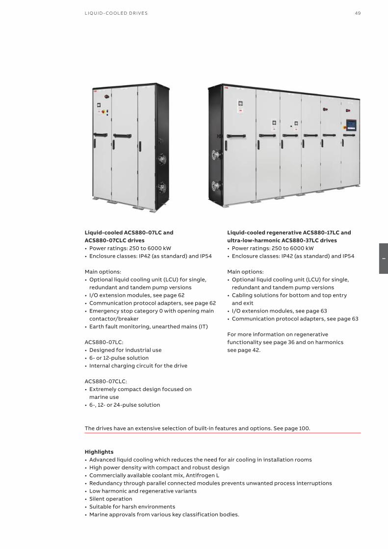
49L I Q U I D - CO O L ED D R I V E S
I
Liquid-cooled ACS880-07LC and ACS880-07CLC drives• Power ratings: 250 to 6000 kW• Enclosure classes: IP42 (as standard) and IP54
Main options: • Optional liquid cooling unit (LCU) for single,
redundant and tandem pump versions• I/O extension modules, see page 62• Communication protocol adapters, see page 62• Emergency stop category 0 with opening main
contactor/breaker• Earth fault monitoring, unearthed mains (IT)
ACS880-07LC:• Designed for industrial use• 6- or 12-pulse solution• Internal charging circuit for the drive
ACS880-07CLC:• Extremely compact design focused on
marine use • 6-, 12- or 24-pulse solution
Highlights• Advanced liquid cooling which reduces the need for air cooling in installation rooms• High power density with compact and robust design• Commercially available coolant mix, Antifrogen L• Redundancy through parallel connected modules prevents unwanted process interruptions• Low harmonic and regenerative variants• Silent operation• Suitable for harsh environments• Marine approvals from various key classification bodies.
The drives have an extensive selection of built-in features and options. See page 100.
Liquid-cooled regenerative ACS880-17LC and ultra-low-harmonic ACS880-37LC drives• Power ratings: 250 to 6000 kW• Enclosure classes: IP42 (as standard) and IP54
Main options: • Optional liquid cooling unit (LCU) for single,
redundant and tandem pump versions• Cabling solutions for bottom and top entry
and exit• I/O extension modules, see page 63• Communication protocol adapters, see page 63
For more information on regenerative functionality see page 36 and on harmonics see page 42.
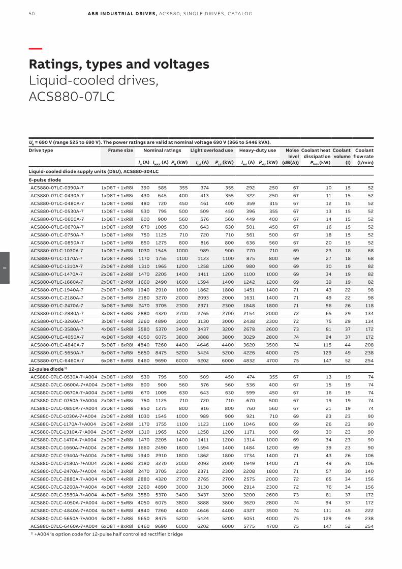
50 A B B I N D U S TR I A L D R I V E S , AC S 8 8 0, S I N G L E D R I V E S , C ATA LO G
I
—Ratings, types and voltagesLiquid-cooled drives, ACS880-07LC
UN = 690 V (range 525 to 690 V). The power ratings are valid at nominal voltage 690 V (366 to 5446 kVA).
Drive type Frame size Nominal ratings Light overload use Heavy-duty use Noiselevel
(dB(A))
Coolant heatdissipation
Ploss (kW)
Coolantvolume
(l)
Coolant flow rate
(l/min)IN (A) IMAX (A) PN (kW) ILd (A) PLd (kW) IHd (A) PHd (kW)
Liquid-cooled diode supply units (DSU), ACS880-304LC
6-pulse diode
ACS880-07LC-0390A-7 1xD8T + 1xR8i 390 585 355 374 355 292 250 67 10 15 52
ACS880-07LC-0430A-7 1xD8T + 1xR8i 430 645 400 413 355 322 250 67 11 15 52
ACS880-07LC-0480A-7 1xD8T + 1xR8i 480 720 450 461 400 359 315 67 12 15 52
ACS880-07LC-0530A-7 1xD8T + 1xR8i 530 795 500 509 450 396 355 67 13 15 52
ACS880-07LC-0600A-7 1xD8T + 1xR8i 600 900 560 576 560 449 400 67 14 15 52
ACS880-07LC-0670A-7 1xD8T + 1xR8i 670 1005 630 643 630 501 450 67 16 15 52
ACS880-07LC-0750A-7 1xD8T + 1xR8i 750 1125 710 720 710 561 500 67 18 15 52
ACS880-07LC-0850A-7 1xD8T + 1xR8i 850 1275 800 816 800 636 560 67 20 15 52
ACS880-07LC-1030A-7 1xD8T + 2xR8i 1030 1545 1000 989 900 770 710 69 23 18 68
ACS880-07LC-1170A-7 1xD8T + 2xR8i 1170 1755 1100 1123 1100 875 800 69 27 18 68
ACS880-07LC-1310A-7 2xD8T + 2xR8i 1310 1965 1200 1258 1200 980 900 69 30 19 82
ACS880-07LC-1470A-7 2xD8T + 2xR8i 1470 2205 1400 1411 1200 1100 1000 69 34 19 82
ACS880-07LC-1660A-7 2xD8T + 2xR8i 1660 2490 1600 1594 1400 1242 1200 69 39 19 82
ACS880-07LC-1940A-7 2xD8T + 3xR8i 1940 2910 1800 1862 1800 1451 1400 71 43 22 98
ACS880-07LC-2180A-7 2xD8T + 3xR8i 2180 3270 2000 2093 2000 1631 1400 71 49 22 98
ACS880-07LC-2470A-7 3xD8T + 3xR8i 2470 3705 2300 2371 2300 1848 1800 71 56 26 118
ACS880-07LC-2880A-7 3xD8T + 4xR8i 2880 4320 2700 2765 2700 2154 2000 72 65 29 134
ACS880-07LC-3260A-7 3xD8T + 4xR8i 3260 4890 3000 3130 3000 2438 2300 72 75 29 134
ACS880-07LC-3580A-7 4xD8T + 5xR8i 3580 5370 3400 3437 3200 2678 2600 73 81 37 172
ACS880-07LC-4050A-7 4xD8T + 5xR8i 4050 6075 3800 3888 3800 3029 2800 74 94 37 172
ACS880-07LC-4840A-7 5xD8T + 6xR8i 4840 7260 4400 4646 4400 3620 3500 74 115 44 208
ACS880-07LC-5650A-7 6xD8T + 7xR8i 5650 8475 5200 5424 5200 4226 4000 75 129 49 238
ACS880-07LC-6460A-7 6xD8T + 8xR8i 6460 9690 6000 6202 6000 4832 4700 75 147 52 254
12-pulse diode 1)
ACS880-07LC-0530A-7+A004 2xD8T + 1xR8i 530 795 500 509 450 474 355 67 13 19 74
ACS880-07LC-0600A-7+A004 2xD8T + 1xR8i 600 900 560 576 560 536 400 67 15 19 74
ACS880-07LC-0670A-7+A004 2xD8T + 1xR8i 670 1005 630 643 630 599 450 67 16 19 74
ACS880-07LC-0750A-7+A004 2xD8T + 1xR8i 750 1125 710 720 710 670 500 67 19 19 74
ACS880-07LC-0850A-7+A004 2xD8T + 1xR8i 850 1275 800 816 800 760 560 67 21 19 74
ACS880-07LC-1030A-7+A004 2xD8T + 2xR8i 1030 1545 1000 989 900 921 710 69 23 23 90
ACS880-07LC-1170A-7+A004 2xD8T + 2xR8i 1170 1755 1100 1123 1100 1046 800 69 26 23 90
ACS880-07LC-1310A-7+A004 2xD8T + 2xR8i 1310 1965 1200 1258 1200 1171 900 69 30 23 90
ACS880-07LC-1470A-7+A004 2xD8T + 2xR8i 1470 2205 1400 1411 1200 1314 1000 69 34 23 90
ACS880-07LC-1660A-7+A004 2xD8T + 2xR8i 1660 2490 1600 1594 1400 1484 1200 69 39 23 90
ACS880-07LC-1940A-7+A004 2xD8T + 3xR8i 1940 2910 1800 1862 1800 1734 1400 71 43 26 106
ACS880-07LC-2180A-7+A004 2xD8T + 3xR8i 2180 3270 2000 2093 2000 1949 1400 71 49 26 106
ACS880-07LC-2470A-7+A004 4xD8T + 3xR8i 2470 3705 2300 2371 2300 2208 1800 71 57 30 140
ACS880-07LC-2880A-7+A004 4xD8T + 4xR8i 2880 4320 2700 2765 2700 2575 2000 72 65 34 156
ACS880-07LC-3260A-7+A004 4xD8T + 4xR8i 3260 4890 3000 3130 3000 2914 2300 72 76 34 156
ACS880-07LC-3580A-7+A004 4xD8T + 5xR8i 3580 5370 3400 3437 3200 3200 2600 73 81 37 172
ACS880-07LC-4050A-7+A004 4xD8T + 5xR8i 4050 6075 3800 3888 3800 3620 2800 74 94 37 172
ACS880-07LC-4840A-7+A004 6xD8T + 6xR8i 4840 7260 4400 4646 4400 4327 3500 74 111 45 222
ACS880-07LC-5650A-7+A004 6xD8T + 7xR8i 5650 8475 5200 5424 5200 5051 4000 75 129 49 238
ACS880-07LC-6460A-7+A004 6xD8T + 8xR8i 6460 9690 6000 6202 6000 5775 4700 75 147 52 2541) +A004 is option code for 12-pulse half controlled rectifier bridge
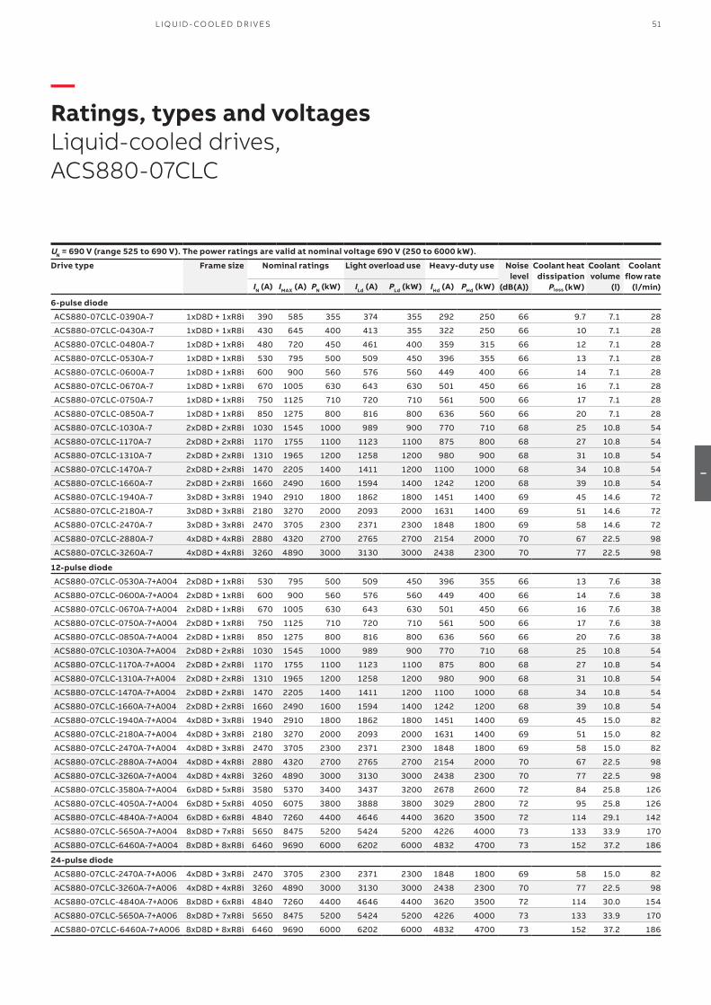
51L I Q U I D - CO O L ED D R I V E S
I
—Ratings, types and voltagesLiquid-cooled drives, ACS880-07CLC
UN = 690 V (range 525 to 690 V). The power ratings are valid at nominal voltage 690 V (250 to 6000 kW).
Drive type Frame size Nominal ratings Light overload use Heavy-duty use Noiselevel
(dB(A))
Coolant heatdissipation
Ploss (kW)
Coolantvolume
(l)
Coolant flow rate
(l/min)IN (A) IMAX (A) PN (kW) ILd (A) PLd (kW) IHd (A) PHd (kW)
6-pulse diode
ACS880-07CLC-0390A-7 1xD8D + 1xR8i 390 585 355 374 355 292 250 66 9.7 7.1 28
ACS880-07CLC-0430A-7 1xD8D + 1xR8i 430 645 400 413 355 322 250 66 10 7.1 28
ACS880-07CLC-0480A-7 1xD8D + 1xR8i 480 720 450 461 400 359 315 66 12 7.1 28
ACS880-07CLC-0530A-7 1xD8D + 1xR8i 530 795 500 509 450 396 355 66 13 7.1 28
ACS880-07CLC-0600A-7 1xD8D + 1xR8i 600 900 560 576 560 449 400 66 14 7.1 28
ACS880-07CLC-0670A-7 1xD8D + 1xR8i 670 1005 630 643 630 501 450 66 16 7.1 28
ACS880-07CLC-0750A-7 1xD8D + 1xR8i 750 1125 710 720 710 561 500 66 17 7.1 28
ACS880-07CLC-0850A-7 1xD8D + 1xR8i 850 1275 800 816 800 636 560 66 20 7.1 28
ACS880-07CLC-1030A-7 2xD8D + 2xR8i 1030 1545 1000 989 900 770 710 68 25 10.8 54
ACS880-07CLC-1170A-7 2xD8D + 2xR8i 1170 1755 1100 1123 1100 875 800 68 27 10.8 54
ACS880-07CLC-1310A-7 2xD8D + 2xR8i 1310 1965 1200 1258 1200 980 900 68 31 10.8 54
ACS880-07CLC-1470A-7 2xD8D + 2xR8i 1470 2205 1400 1411 1200 1100 1000 68 34 10.8 54
ACS880-07CLC-1660A-7 2xD8D + 2xR8i 1660 2490 1600 1594 1400 1242 1200 68 39 10.8 54
ACS880-07CLC-1940A-7 3xD8D + 3xR8i 1940 2910 1800 1862 1800 1451 1400 69 45 14.6 72
ACS880-07CLC-2180A-7 3xD8D + 3xR8i 2180 3270 2000 2093 2000 1631 1400 69 51 14.6 72
ACS880-07CLC-2470A-7 3xD8D + 3xR8i 2470 3705 2300 2371 2300 1848 1800 69 58 14.6 72
ACS880-07CLC-2880A-7 4xD8D + 4xR8i 2880 4320 2700 2765 2700 2154 2000 70 67 22.5 98
ACS880-07CLC-3260A-7 4xD8D + 4xR8i 3260 4890 3000 3130 3000 2438 2300 70 77 22.5 98
12-pulse diode
ACS880-07CLC-0530A-7+A004 2xD8D + 1xR8i 530 795 500 509 450 396 355 66 13 7.6 38
ACS880-07CLC-0600A-7+A004 2xD8D + 1xR8i 600 900 560 576 560 449 400 66 14 7.6 38
ACS880-07CLC-0670A-7+A004 2xD8D + 1xR8i 670 1005 630 643 630 501 450 66 16 7.6 38
ACS880-07CLC-0750A-7+A004 2xD8D + 1xR8i 750 1125 710 720 710 561 500 66 17 7.6 38
ACS880-07CLC-0850A-7+A004 2xD8D + 1xR8i 850 1275 800 816 800 636 560 66 20 7.6 38
ACS880-07CLC-1030A-7+A004 2xD8D + 2xR8i 1030 1545 1000 989 900 770 710 68 25 10.8 54
ACS880-07CLC-1170A-7+A004 2xD8D + 2xR8i 1170 1755 1100 1123 1100 875 800 68 27 10.8 54
ACS880-07CLC-1310A-7+A004 2xD8D + 2xR8i 1310 1965 1200 1258 1200 980 900 68 31 10.8 54
ACS880-07CLC-1470A-7+A004 2xD8D + 2xR8i 1470 2205 1400 1411 1200 1100 1000 68 34 10.8 54
ACS880-07CLC-1660A-7+A004 2xD8D + 2xR8i 1660 2490 1600 1594 1400 1242 1200 68 39 10.8 54
ACS880-07CLC-1940A-7+A004 4xD8D + 3xR8i 1940 2910 1800 1862 1800 1451 1400 69 45 15.0 82
ACS880-07CLC-2180A-7+A004 4xD8D + 3xR8i 2180 3270 2000 2093 2000 1631 1400 69 51 15.0 82
ACS880-07CLC-2470A-7+A004 4xD8D + 3xR8i 2470 3705 2300 2371 2300 1848 1800 69 58 15.0 82
ACS880-07CLC-2880A-7+A004 4xD8D + 4xR8i 2880 4320 2700 2765 2700 2154 2000 70 67 22.5 98
ACS880-07CLC-3260A-7+A004 4xD8D + 4xR8i 3260 4890 3000 3130 3000 2438 2300 70 77 22.5 98
ACS880-07CLC-3580A-7+A004 6xD8D + 5xR8i 3580 5370 3400 3437 3200 2678 2600 72 84 25.8 126
ACS880-07CLC-4050A-7+A004 6xD8D + 5xR8i 4050 6075 3800 3888 3800 3029 2800 72 95 25.8 126
ACS880-07CLC-4840A-7+A004 6xD8D + 6xR8i 4840 7260 4400 4646 4400 3620 3500 72 114 29.1 142
ACS880-07CLC-5650A-7+A004 8xD8D + 7xR8i 5650 8475 5200 5424 5200 4226 4000 73 133 33.9 170
ACS880-07CLC-6460A-7+A004 8xD8D + 8xR8i 6460 9690 6000 6202 6000 4832 4700 73 152 37.2 186
24-pulse diode
ACS880-07CLC-2470A-7+A006 4xD8D + 3xR8i 2470 3705 2300 2371 2300 1848 1800 69 58 15.0 82
ACS880-07CLC-3260A-7+A006 4xD8D + 4xR8i 3260 4890 3000 3130 3000 2438 2300 70 77 22.5 98
ACS880-07CLC-4840A-7+A006 8xD8D + 6xR8i 4840 7260 4400 4646 4400 3620 3500 72 114 30.0 154
ACS880-07CLC-5650A-7+A006 8xD8D + 7xR8i 5650 8475 5200 5424 5200 4226 4000 73 133 33.9 170
ACS880-07CLC-6460A-7+A006 8xD8D + 8xR8i 6460 9690 6000 6202 6000 4832 4700 73 152 37.2 186
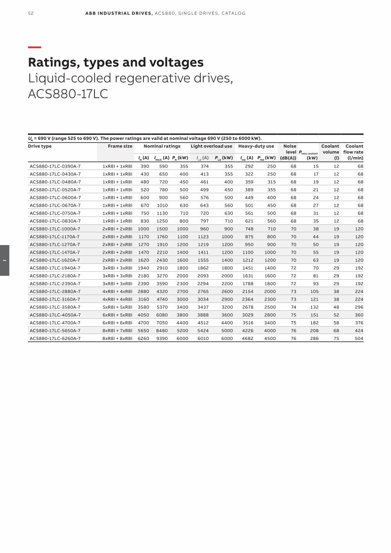
52 A B B I N D U S TR I A L D R I V E S , AC S 8 8 0, S I N G L E D R I V E S , C ATA LO G
I
—Ratings, types and voltagesLiquid-cooled regenerative drives, ACS880-17LC
UN = 690 V (range 525 to 690 V). The power ratings are valid at nominal voltage 690 V (250 to 6000 kW).
Drive type Frame size Nominal ratings Light overload use Heavy-duty use Noiselevel
(dB(A))Ploss coolant
(kW)
Coolantvolume
(l)
Coolant flow rate
(l/min)IN (A) IMAX (A) PN (kW) ILd (A) PLd (kW) IHd (A) PHd (kW)
ACS880-17LC-0390A-7 1xR8i + 1xR8i 390 590 355 374 355 292 250 68 15 12 68
ACS880-17LC-0430A-7 1xR8i + 1xR8i 430 650 400 413 355 322 250 68 17 12 68
ACS880-17LC-0480A-7 1xR8i + 1xR8i 480 720 450 461 400 359 315 68 19 12 68
ACS880-17LC-0520A-7 1xR8i + 1xR8i 520 780 500 499 450 389 355 68 21 12 68
ACS880-17LC-0600A-7 1xR8i + 1xR8i 600 900 560 576 500 449 400 68 24 12 68
ACS880-17LC-0670A-7 1xR8i + 1xR8i 670 1010 630 643 560 501 450 68 27 12 68
ACS880-17LC-0750A-7 1xR8i + 1xR8i 750 1130 710 720 630 561 500 68 31 12 68
ACS880-17LC-0830A-7 1xR8i + 1xR8i 830 1250 800 797 710 621 560 68 35 12 68
ACS880-17LC-1000A-7 2xR8i + 2xR8i 1000 1500 1000 960 900 748 710 70 38 19 120
ACS880-17LC-1170A-7 2xR8i + 2xR8i 1170 1760 1100 1123 1000 875 800 70 44 19 120
ACS880-17LC-1270A-7 2xR8i + 2xR8i 1270 1910 1200 1219 1200 950 900 70 50 19 120
ACS880-17LC-1470A-7 2xR8i + 2xR8i 1470 2210 1400 1411 1200 1100 1000 70 55 19 120
ACS880-17LC-1620A-7 2xR8i + 2xR8i 1620 2430 1600 1555 1400 1212 1200 70 63 19 120
ACS880-17LC-1940A-7 3xR8i + 3xR8i 1940 2910 1800 1862 1800 1451 1400 72 70 29 192
ACS880-17LC-2180A-7 3xR8i + 3xR8i 2180 3270 2000 2093 2000 1631 1600 72 81 29 192
ACS880-17LC-2390A-7 3xR8i + 3xR8i 2390 3590 2300 2294 2200 1788 1800 72 93 29 192
ACS880-17LC-2880A-7 4xR8i + 4xR8i 2880 4320 2700 2765 2600 2154 2000 73 105 38 224
ACS880-17LC-3160A-7 4xR8i + 4xR8i 3160 4740 3000 3034 2900 2364 2300 73 121 38 224
ACS880-17LC-3580A-7 5xR8i + 5xR8i 3580 5370 3400 3437 3200 2678 2500 74 132 48 296
ACS880-17LC-4050A-7 6xR8i + 5xR8i 4050 6080 3800 3888 3600 3029 2800 75 151 52 360
ACS880-17LC-4700A-7 6xR8i + 6xR8i 4700 7050 4400 4512 4400 3516 3400 75 182 58 376
ACS880-17LC-5650A-7 8xR8i + 7xR8i 5650 8480 5200 5424 5000 4226 4000 76 208 68 424
ACS880-17LC-6260A-7 8xR8i + 8xR8i 6260 9390 6000 6010 6000 4682 4500 76 286 75 504
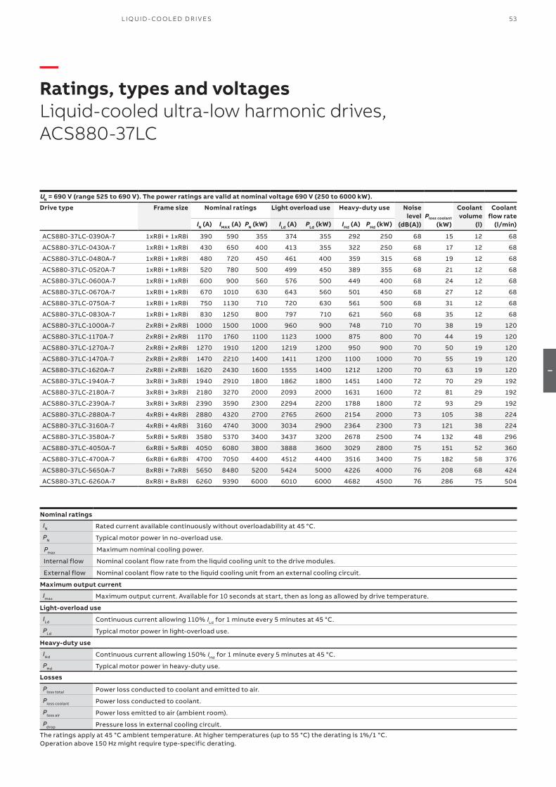
53L I Q U I D - CO O L ED D R I V E S
I
—Ratings, types and voltagesLiquid-cooled ultra-low harmonic drives, ACS880-37LC
UN = 690 V (range 525 to 690 V). The power ratings are valid at nominal voltage 690 V (250 to 6000 kW).
Drive type Frame size Nominal ratings Light overload use Heavy-duty use Noiselevel
(dB(A))Ploss coolant
(kW)
Coolantvolume
(l)
Coolant flow rate
(l/min)IN (A) IMAX (A) PN (kW) ILd (A) PLd (kW) IHd (A) PHd (kW)
ACS880-37LC-0390A-7 1xR8i + 1xR8i 390 590 355 374 355 292 250 68 15 12 68
ACS880-37LC-0430A-7 1xR8i + 1xR8i 430 650 400 413 355 322 250 68 17 12 68
ACS880-37LC-0480A-7 1xR8i + 1xR8i 480 720 450 461 400 359 315 68 19 12 68
ACS880-37LC-0520A-7 1xR8i + 1xR8i 520 780 500 499 450 389 355 68 21 12 68
ACS880-37LC-0600A-7 1xR8i + 1xR8i 600 900 560 576 500 449 400 68 24 12 68
ACS880-37LC-0670A-7 1xR8i + 1xR8i 670 1010 630 643 560 501 450 68 27 12 68
ACS880-37LC-0750A-7 1xR8i + 1xR8i 750 1130 710 720 630 561 500 68 31 12 68
ACS880-37LC-0830A-7 1xR8i + 1xR8i 830 1250 800 797 710 621 560 68 35 12 68
ACS880-37LC-1000A-7 2xR8i + 2xR8i 1000 1500 1000 960 900 748 710 70 38 19 120
ACS880-37LC-1170A-7 2xR8i + 2xR8i 1170 1760 1100 1123 1000 875 800 70 44 19 120
ACS880-37LC-1270A-7 2xR8i + 2xR8i 1270 1910 1200 1219 1200 950 900 70 50 19 120
ACS880-37LC-1470A-7 2xR8i + 2xR8i 1470 2210 1400 1411 1200 1100 1000 70 55 19 120
ACS880-37LC-1620A-7 2xR8i + 2xR8i 1620 2430 1600 1555 1400 1212 1200 70 63 19 120
ACS880-37LC-1940A-7 3xR8i + 3xR8i 1940 2910 1800 1862 1800 1451 1400 72 70 29 192
ACS880-37LC-2180A-7 3xR8i + 3xR8i 2180 3270 2000 2093 2000 1631 1600 72 81 29 192
ACS880-37LC-2390A-7 3xR8i + 3xR8i 2390 3590 2300 2294 2200 1788 1800 72 93 29 192
ACS880-37LC-2880A-7 4xR8i + 4xR8i 2880 4320 2700 2765 2600 2154 2000 73 105 38 224
ACS880-37LC-3160A-7 4xR8i + 4xR8i 3160 4740 3000 3034 2900 2364 2300 73 121 38 224
ACS880-37LC-3580A-7 5xR8i + 5xR8i 3580 5370 3400 3437 3200 2678 2500 74 132 48 296
ACS880-37LC-4050A-7 6xR8i + 5xR8i 4050 6080 3800 3888 3600 3029 2800 75 151 52 360
ACS880-37LC-4700A-7 6xR8i + 6xR8i 4700 7050 4400 4512 4400 3516 3400 75 182 58 376
ACS880-37LC-5650A-7 8xR8i + 7xR8i 5650 8480 5200 5424 5000 4226 4000 76 208 68 424
ACS880-37LC-6260A-7 8xR8i + 8xR8i 6260 9390 6000 6010 6000 4682 4500 76 286 75 504
Nominal ratings
IN Rated current available continuously without overloadability at 45 °C.
PN Typical motor power in no-overload use.
Pmax Maximum nominal cooling power.
Internal flow Nominal coolant flow rate from the liquid cooling unit to the drive modules.
External flow Nominal coolant flow rate to the liquid cooling unit from an external cooling circuit.
Maximum output current
Imax Maximum output current. Available for 10 seconds at start, then as long as allowed by drive temperature.
Light-overload use
ILd Continuous current allowing 110% ILd for 1 minute every 5 minutes at 45 °C.
PLd Typical motor power in light-overload use.
Heavy-duty use
IHd Continuous current allowing 150% IHd for 1 minute every 5 minutes at 45 °C.
PHd Typical motor power in heavy-duty use.
Losses
Ploss total Power loss conducted to coolant and emitted to air.
Ploss coolant Power loss conducted to coolant.
Ploss air Power loss emitted to air (ambient room).
Pdrop Pressure loss in external cooling circuit.
The ratings apply at 45 °C ambient temperature. At higher temperatures (up to 55 °C) the derating is 1%/1 °C. Operation above 150 Hz might require type-specific derating.
54 A B B I N D U S TR I A L D R I V E S , AC S 8 8 0, S I N G L E D R I V E S , C ATA LO G
I
Range 380 to 690 V
Liquid cooling unit type Nominal ratings Noise level
Losses Internal flow 1) External flow 2)
Internal coolant volume
Externalcoolant volume
Pmax (kW) (l) (l) (dB(A))
Ploss total (kW)
Ploss coolant
(kW)Ploss air
(kW)Pdrop
(kPa) (l/min) (l/min)
ACS880-1007LC-0070 3) 70 17 3 55 0.4 0.3 0.1 150 81/107 120
ACS880-1007LC-0195+C140 3)/C1414) 195 31/35 8 55 1.3 1.0 0.3 150 270/355 467
ACS880-1007LC-0195+C213 5) 195 35 8 57 2.1 1.8 0.3 150 310/415 4671) 120 kPa, Antifrogen® L 25%, 40 °C, 50/60 Hz2) 36 °C water3) Single pump 4) Redundant, one pump running5) Two pumps running
—Ratings, types and voltagesLiquid-cooling unit, ACS880-1007LC
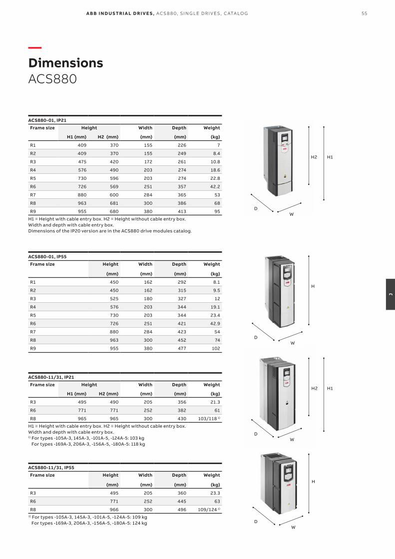
55A B B I N D U S TR I A L D R I V E S , AC S 8 8 0, S I N G L E D R I V E S , C ATA LO G
J
—DimensionsACS880
ACS880-01, IP21
Frame size Height Width Depth Weight
H1 (mm) H2 (mm) (mm) (mm) (kg)
R1 409 370 155 226 7
R2 409 370 155 249 8.4
R3 475 420 172 261 10.8
R4 576 490 203 274 18.6
R5 730 596 203 274 22.8
R6 726 569 251 357 42.2
R7 880 600 284 365 53
R8 963 681 300 386 68
R9 955 680 380 413 95
H1 = Height with cable entry box. H2 = Height without cable entry box. Width and depth with cable entry box. Dimensions of the IP20 version are in the ACS880 drive modules catalog.
ACS880-11/31, IP55
Frame size Height Width Depth Weight
(mm) (mm) (mm) (kg)
R3 495 205 360 23.3
R6 771 252 445 63
R8 966 300 496 109/124 1)
1) For types -105A-3, 145A-3, -101A-5, -124A-5: 109 kgFor types -169A-3, 206A-3, -156A-5, -180A-5: 124 kg
ACS880-01, IP55
Frame size Height Width Depth Weight
(mm) (mm) (mm) (kg)
R1 450 162 292 8.1
R2 450 162 315 9.5
R3 525 180 327 12
R4 576 203 344 19.1
R5 730 203 344 23.4
R6 726 251 421 42.9
R7 880 284 423 54
R8 963 300 452 74
R9 955 380 477 102
WD
H1H2
WD
H1H2
ACS880-11/31, IP21
Frame size Height Width Depth Weight
H1 (mm) H2 (mm) (mm) (mm) (kg)
R3 495 490 205 356 21.3
R6 771 771 252 382 61
R8 965 965 300 430 103/118 1)
H1 = Height with cable entry box. H2 = Height without cable entry box. Width and depth with cable entry box.1) For types -105A-3, 145A-3, -101A-5, -124A-5: 103 kg
For types -169A-3, 206A-3, -156A-5, -180A-5: 118 kg
WD
H
WD
H
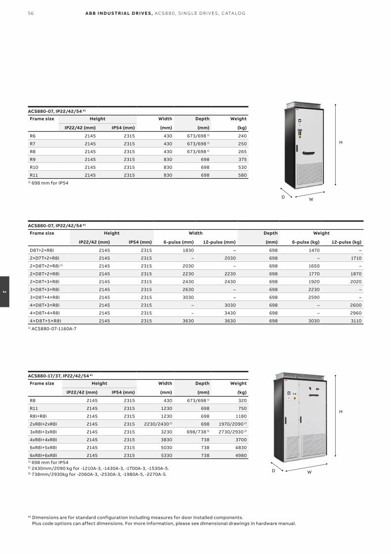
56 A B B I N D U S TR I A L D R I V E S , AC S 8 8 0, S I N G L E D R I V E S , C ATA LO G
J
WD
H
WD
H
ACS880-07, IP22/42/54 *)
Frame size Height Width Depth Weight
IP22/42 (mm) IP54 (mm) (mm) (mm) (kg)
R6 2145 2315 430 673/698 1) 240
R7 2145 2315 430 673/698 1) 250
R8 2145 2315 430 673/698 1) 265
R9 2145 2315 830 698 375
R10 2145 2315 830 698 530
R11 2145 2315 830 698 5801) 698 mm for IP54
ACS880-17/37, IP22/42/54 *)
Frame size Height Width Depth Weight
IP22/42 (mm) IP54 (mm) (mm) (mm) (kg)
R8 2145 2315 430 673/698 1) 320
R11 2145 2315 1230 698 750
R8i+R8i 2145 2315 1230 698 1180
2xR8i+2xR8i 2145 2315 2230/2430 2) 698 1970/2090 2)
3xR8i+3xR8i 2145 2315 3230 698/738 3) 2730/2930 3)
4xR8i+4xR8i 2145 2315 3830 738 3700
6xR8i+5xR8i 2145 2315 5030 738 4830
6xR8i+6xR8i 2145 2315 5330 738 49801) 698 mm for IP542) 2430mm/2090 kg for -1210A-3, -1430A-3, -1700A-3, -1530A-5.3) 738mm/2930kg for -2060A-3, -2530A-3, -1980A-5, -2270A-5.
ACS880-07, IP22/42/54 *)
Frame size Height Width Depth Weight
IP22/42 (mm) IP54 (mm) 6-pulse (mm) 12-pulse (mm) (mm) 6-pulse (kg) 12-pulse (kg)
D8T+2×R8i 2145 2315 1830 – 698 1470 –
2×D7T+2×R8i 2145 2315 – 2030 698 – 1710
2×D8T+2×R8i 1) 2145 2315 2030 – 698 1650 –
2×D8T+2×R8i 2145 2315 2230 2230 698 1770 1870
2×D8T+3×R8i 2145 2315 2430 2430 698 1920 2020
3×D8T+3×R8i 2145 2315 2630 – 698 2230 –
3×D8T+4×R8i 2145 2315 3030 – 698 2590 –
4×D8T+3×R8i 2145 2315 – 3030 698 – 2600
4×D8T+4×R8i 2145 2315 – 3430 698 – 2960
4×D8T+5×R8i 2145 2315 3630 3630 698 3030 31101) ACS880-07-1160A-7
*) Dimensions are for standard configuration including measures for door installed components. Plus code options can affect dimensions. For more information, please see dimensional drawings in hardware manual.

57D I M ENSI O NS
J
ACS880-1007LC, liquid-cooling unit
Unit type Height Width 1) Depth Weight
(mm) (mm) (mm) (kg)
ACS880-1007LC-0070 2002 300/330 636 200
ACS880-1007LC-0195+C140 2002 600/630 636 310
ACS880-1007LC-0195+C141 2002 600/630 636 366
ACS880-1007LC-0195+C213 2002 600/630 636 3731) The first values are for line-up connected unit and the latter values for standalone unit.
ACS880-17/37LC, IP42/54
Frame size Height Width Depth Weight
(mm) (mm) (mm) (kg)
1xR8i+1xR8i 2002 2000 644 2040
2xR8i+2xR8i 2002 2400/2500 1) 644 5070/5400 2)
3xR8i+3xR8i 2002 3200 644 7250
4xR8i+4xR8i 2002 4000 644 9060
5xR8i+5xR8i 2002 4600 644 10470
6xR8i+5xR8i 2002 5800 644 13600
6xR8i+6xR8i 2002 6000 644 13980
8xR8i+7xR8i 2002 7300 644 17020
8xR8i+12xR8i 2002 7600 644 175901) 2400 mm for -1000A-7, - 1170A-7 and -1270A-7. 2500 mm for -1470A-7 and -1620A-7.2) 5070 kg for -1000A-7, - 1170A-7 and -1270A-7. 5400 kg for -1470A-7 and -1620A-7.
WD
H
WD
H
ACS880-07CLC, IP42/54
Frame size Height Width Depth Weight
(mm) (mm) (mm) (kg)
1xD8D+1xR8i 2002 700 636 580
2xD8D+1xR8i 2002 700 636 580
2xD8D+2xR8i 2002 900 636 710
3xD8D+3xR8i 2002 1200 636 1030
4xD8D+3xR8i 2002 1200 636 1030
4xD8D+4xR8i 2002 1500 636 1290
6xD8D+5xR8i 2002 2200 636 1890
6xD8D+6xR8i 2002 2400 636 2060
8xD8D+7xR8i 2002 2700 636 2290
8xD8D+12xR8i 2002 2900 636 2520 WD
H
ACS880-07LC, IP42/54
Frame size Height Width Depth Weight
(mm) 6-pulse (mm) 12-pulse (mm) (mm) 6-pulse (kg) 12-pulse (kg)
1xD8T + 1xR8i 2002 1700 – 644 1480 –
1xD8T + 2xR8i 2002 1900 – 644 1610 –
2xD8T + 1xR8i 2002 – 2300 644 – 2230
2xD8T + 2xR8i 2002 1900 2500 644 1760 2360
2xD8T + 3xR8i 2002 2100 2700 644 1930 2530
3xD8T + 3xR8i 2002 2500 – 644 2230 –
3xD8T + 4xR8i 2002 2800 – 644 2490 –
4xD8T + 3xR8i 2002 – 3240 644 – 2980
4xD8T + 4xR8i 2002 – 3400 644 – 3240
4xD8T + 5xR8i 2002 3600 3600 644 3410 3410
5xD8T + 6xR8i 2002 4500 – 644 3410 –
6xD8T + 6xR8i 2002 – 4200 644 – 4030
6xD8T + 7xR8i 2002 4800 4800 644 4470 4470
6xD8T + 8xR8i 2002 5000 5000 644 4640 4640
WD
H
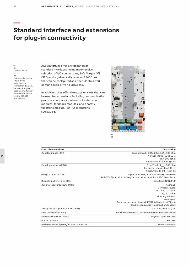
58 A B B I N D U S TR I A L D R I V E S , AC S 8 8 0, S I N G L E D R I V E S , C ATA LO G
K
— Standard interface and extensions for plug-in connectivity
ACS880 drives offer a wide range of standard interfaces including extensiveselection of I/O connections, Safe Torque Off(STO) and a galvanically isolated RS485 linkthat can be configured as either Modbus RTUor high speed drive-to-drive link.
In addition, they offer three option slots that can be used for extensions, including communication protocol adapters, input/output extension modules, feedback modules, and a safety functions module. For I/O extensions, see page 63.
Control connections Description
2 analog inputs (XAI) Current input: -20 to 20 mA, Rin : 100 ohmVoltage input: -10 to 10 V,
Rin > 200 kohmResolution: 11 bit + sign bit
2 analog outputs (XAO) 0 to 20 mA, Rload < 500 ohmFrequency range: 0 to 300 Hz
Resolution: 11 bit + sign bit
6 digital inputs (XDI) Input type: NPN/PNP (DI1 to DI5), NPN (DI6)DI6 (XDI:6) can alternatively be used as an input for a PTC thermistor.
Digital input interlock (DIIL) Input type: NPN/PNP
2 digital inputs/outputs (XDIO) As input:24 V logic levels:
“0” < 5 V, “1” > 15 VRin: 2.0 kohm
Filtering: 0.25 msAs output:
Total output current from 24 V DC is limited to 200 mACan be set as pulse train input and output
3 relay outputs (XRO1, XRO2, XRO3) 250 V AC/30 V DC, 2 A
Safe torque off (XSTO) For the drive to start, both connections must be closed
Drive-to-drive link (XD2D) Physical layer: EIA-485
Built-in Modbus EIA-485
Assistant control panel/PC tool connection Connector: RJ-45
—01
—01 Control unit ZCU—02 Example of a typical single drivesinput/output connection diagram.Variations maybe possible. For further information, please see the ACS880user manual.
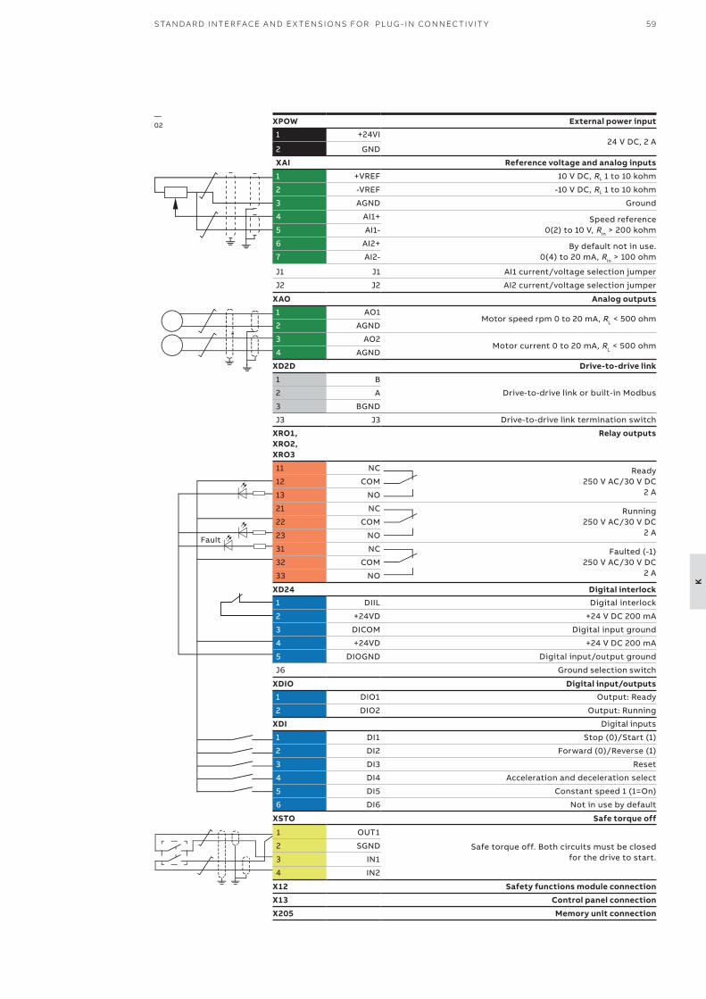
59S TA N DA R D I NTER FACE A N D E X TENSI O NS FO R PLU G - I N CO N N EC TI V IT Y
K
Fault
XPOW External power input1 +24VI
24 V DC, 2 A2 GND
XAI Reference voltage and analog inputs
1 +VREF 10 V DC, RL 1 to 10 kohm
2 -VREF -10 V DC, RL 1 to 10 kohm
3 AGND Ground
4 AI1+ Speed reference 0(2) to 10 V, Rin > 200 kohm5 AI1-
6 AI2+ By default not in use. 0(4) to 20 mA, Rin > 100 ohm 7 AI2-
J1 J1 AI1 current/voltage selection jumper
J2 J2 AI2 current/voltage selection jumper
XAO Analog outputs1 AO1
Motor speed rpm 0 to 20 mA, RL < 500 ohm2 AGND
3 AO2Motor current 0 to 20 mA, RL < 500 ohm
4 AGND
XD2D Drive-to-drive link
1 B
Drive-to-drive link or built-in Modbus2 A
3 BGND
J3 J3 Drive-to-drive link termination switch
XRO1, XRO2, XRO3
Relay outputs
11 NC Ready250 V AC/30 V DC
2 A12 COM
13 NO
21 NC Running250 V AC/30 V DC
2 A22 COM
23 NO
31 NC Faulted (-1)250 V AC/30 V DC
2 A32 COM
33 NO
XD24 Digital interlock1 DIIL Digital interlock
2 +24VD +24 V DC 200 mA
3 DICOM Digital input ground
4 +24VD +24 V DC 200 mA
5 DIOGND Digital input/output ground
J6 Ground selection switch
XDIO Digital input/outputs1 DIO1 Output: Ready
2 DIO2 Output: Running
XDI Digital inputs
1 DI1 Stop (0)/Start (1)
2 DI2 Forward (0)/Reverse (1)
3 DI3 Reset
4 DI4 Acceleration and deceleration select
5 DI5 Constant speed 1 (1=On)
6 DI6 Not in use by default
XSTO Safe torque off
1 OUT1
Safe torque off. Both circuits must be closed for the drive to start.
2 SGND
3 IN1
4 IN2
X12 Safety functions module connection
X13 Control panel connection
X205 Memory unit connection
—02
60
L
A B B I N D U S TR I A L D R I V E S , AC S 8 8 0, S I N G L E D R I V E S , C ATA LO G
—02
—01
—Control panel options
Standard Bluetooth assistant control panel, ACS-AP-W and Industrial assistant control panel, ACS-AP-IAssistant control panel with clear multilingual graphical display can be used for parameter setting and back-up, drive monitoring and operation, fault tracing and as a USB link for a PC tool. There are two different assistant control panels – with (ACS-AP-W) or without (ACS-AP-I) Bluetooth. The panels can be mounted either on the drive or on the door of the enclosure and they are compatible with any ABB all-compatible drive.
Control panel helps you to set up the essential settings quickly and get the drive into action. Also diagnostics is easy due to event history, clear text messages and real-time stamps.
The Bluetooth connection enables the use of mobile apps like Drivetune. This app is available for free on the Google Play and the Apple App
Option code
Ordering code for loose item
Description Type
+0J400 – No control panel –
– 3AXD0000025965 Bluetooth Assistant control panel. Included as standard. ACS-AP-W
+J425 3AUA0000088311 Industrial assistant control panel without Bluetooth connection ACS-AP-I
+J410 3AUA0000108878 Control panel mounting platform, flush mounted, IP54 / UL Type 12 (does not include control panel)
DPMP-01
+J413 3AXD50000009374 Control panel mounting platform, surface mounted, IP65 / UL Type 12 (does not include control panel)
DPMP-02
– 3AXD50000217717 Control panel mounting platform for outdoor and harsh environments, IP66, UV resistance, IK07 impact protection rating
(does not include control panel)
DPMP-04
—Control panel optionsBluetooth Assistant control panel ACS-AP-W is included as standard in the delivery.ACS-AP-W (+J400) can be replaced by +J options below.
—01 Bluetooth assistant control panel, ACS-AP-W—02 Industrial assistant control panel without Bluetooth, ACS-AP-I—03 Control panel mounting platform DPMP-01—04 Control panel mounting platform DPMP-02—05 Control panel mounting platform, DPMP-04
—03
store. Drivetune features include: commissioning, troubleshooting, monitoring and controlling the drive remotely. Drivetune also has full parameter access and backup and restore functionality.
Control panel mounting platform, DPMP-01,is for flush mountings and has IP54/UL Type 12 protection class (IP20, when control panel is not mounted). Supports daisy chaining of the control panel link.
Control panel mounting platform, DPMP-02,is for surface mounting and has IP65 / UL Type 12 protection class (IP20, when control panel not mounted).
Control panel mounting platform, DPMP-04, is a lockable door mounting platform for drive control panels in outdoor installations or harsh environments. It has a IP66 protection class, UV resistance and IK07 impact protection rating.
—04
—05
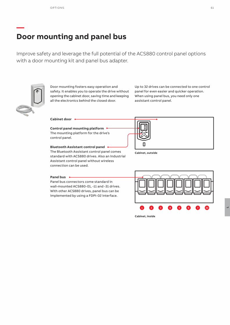
61O P TI O NS
L
—Door mounting and panel bus
Improve safety and leverage the full potential of the ACS880 control panel options with a door mounting kit and panel bus adapter.
1 2 3 4 5 6 7 32
Cabinet door
Control panel mounting platformThe mounting platform for the driveʼs control panel.
Bluetooth Assistant control panelThe Bluetooth Assistant control panel comes standard with ACS880 drives. Also an Industrial Assistant control panel without wireless connection can be used.
Panel busPanel bus connectors come standard in wall-mounted ACS880-01, -11 and -31 drives. With other ACS880 drives, panel bus can be implemented by using a FDPI-02 interface.
Door mounting fosters easy operation and safety. It enables you to operate the drive without opening the cabinet door, saving time and keeping all the electronics behind the closed door.
Cabinet, outside
Cabinet, inside
Up to 32 drives can be connected to one control panel for even easier and quicker operation. When using panel bus, you need only one assistant control panel.

—Communication and connectivityFast and reliable communication
The F-series fieldbus adapter modules are flexible, plug-in adapters that provide fast and simple universal connectivity to all major controllers. Universal connectivity means ABB low voltage drives connect to automation controllers and communication networks, allowing users to choose the best network to meet their needs.
• Reduces mechanical and electrical cost• Decrease in downtime• Increase in productivity• Diminished start-up costs• Lower maintenance and diagnostic costs• Quick access to networked drives with PC-based
start-up and maintenance software tools• Reductions in wiring costs compared to traditional
I/O connections
—Industrial automation plant – different network possibilities and their secure deployment
1
2
5
6
3
4
Trusted networkUntrusted networkConnection between devices
My ABBcustomerportal
NETA-21webpageaccess
Remote accesseither through ownconnection or viaplant access
Remote desktop connection(Drive Composer)
Local PC
PLCNETA-21
HTTPS
USB
Local PC / DriveComposer
Drive Composer prowebpage access
Drive IECprogrammingusing AutomationBuilder
Local PC
Automationbuilder andDrive Manager
NETA-21
Local PCDrive Composer(or MODBUS/TCPmaster)
Local PC
Gateway mode
1. Local connections (point-to-point serial communication, e.g. USB) or2. Shared (with control) upper-level physical fieldbus network (e.g., PROFINET) using Ethernet tool communication and/or3. Communicating also through PLC system using Drive Manager device tool or4. NETA-21 remote monitoring tool web interface or5. NETA-21 acting as a gateway between or6. Third-party remote desktop connection.
62
L
A B B I N D U S TR I A L D R I V E S , AC S 8 8 0, S I N G L E D R I V E S , C ATA LO G
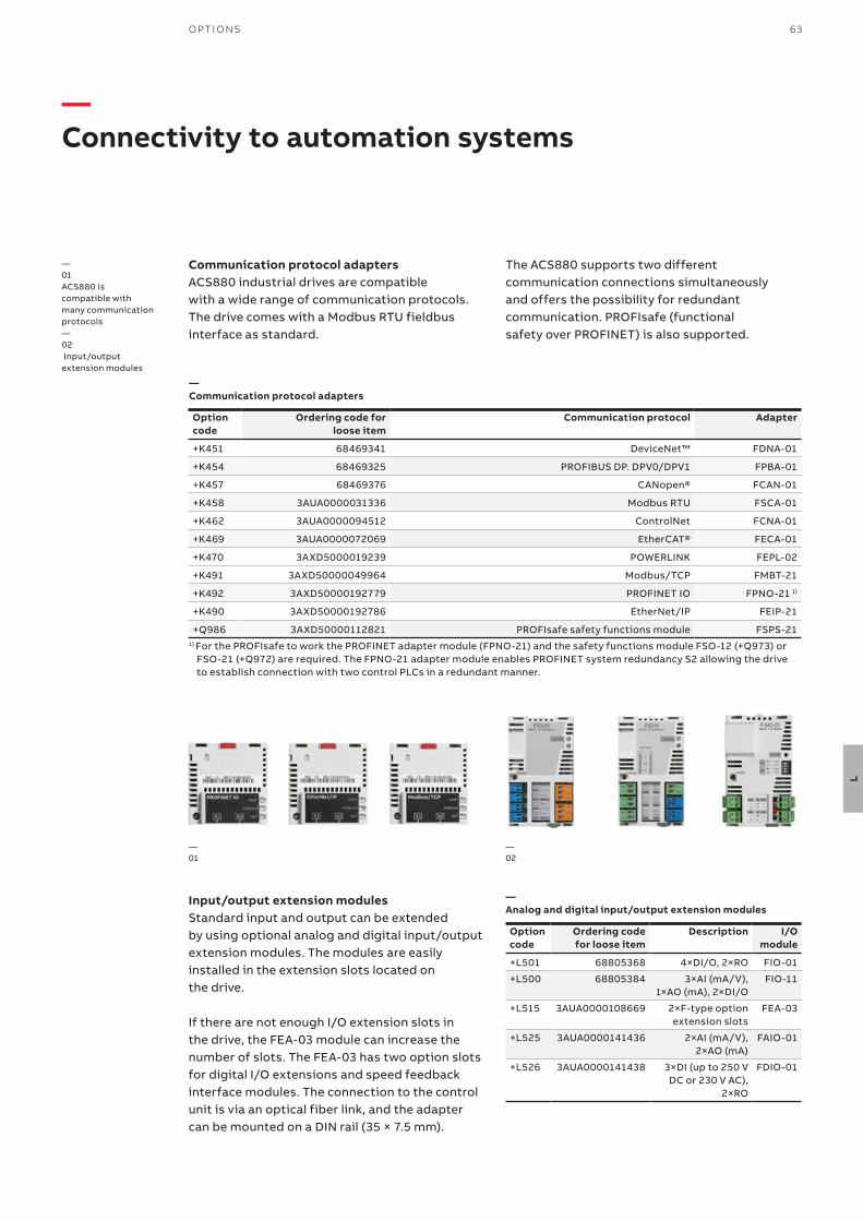
63O P TI O NS
L
—Connectivity to automation systems
Option code
Ordering code for loose item
Communication protocol Adapter
+K451 68469341 DeviceNet™ FDNA-01
+K454 68469325 PROFIBUS DP. DPV0/DPV1 FPBA-01
+K457 68469376 CANopen® FCAN-01
+K458 3AUA0000031336 Modbus RTU FSCA-01
+K462 3AUA0000094512 ControlNet FCNA-01
+K469 3AUA0000072069 EtherCAT® FECA-01
+K470 3AXD5000019239 POWERLINK FEPL-02
+K491 3AXD50000049964 Modbus/TCP FMBT-21
+K492 3AXD50000192779 PROFINET IO FPNO-21 1)
+K490 3AXD50000192786 EtherNet/IP FEIP-21
+Q986 3AXD50000112821 PROFIsafe safety functions module FSPS-211) For the PROFIsafe to work the PROFINET adapter module (FPNO-21) and the safety functions module FSO-12 (+Q973) or
FSO-21 (+Q972) are required. The FPNO-21 adapter module enables PROFINET system redundancy S2 allowing the drive to establish connection with two control PLCs in a redundant manner.
Option code
Ordering code for loose item
Description I/O module
+L501 68805368 4×DI/O, 2×RO FIO-01
+L500 68805384 3×AI (mA/V), 1×AO (mA), 2×DI/O
FIO-11
+L515 3AUA0000108669 2×F-type option extension slots
FEA-03
+L525 3AUA0000141436 2×AI (mA/V), 2×AO (mA)
FAIO-01
+L526 3AUA0000141438 3×DI (up to 250 V DC or 230 V AC),
2×RO
FDIO-01
Communication protocol adaptersACS880 industrial drives are compatible with a wide range of communication protocols. The drive comes with a Modbus RTU fieldbus interface as standard.
—01 ACS880 is compatible with many communication protocols —02 Input/output extension modules
—01
Input/output extension modulesStandard input and output can be extended by using optional analog and digital input/output extension modules. The modules are easily installed in the extension slots located on the drive.
If there are not enough I/O extension slots in the drive, the FEA-03 module can increase the number of slots. The FEA-03 has two option slots for digital I/O extensions and speed feedback interface modules. The connection to the control unit is via an optical fiber link, and the adapter can be mounted on a DIN rail (35 × 7.5 mm).
—Communication protocol adapters
—Analog and digital input/output extension modules
—02
The ACS880 supports two different communication connections simultaneously and offers the possibility for redundant communication. PROFIsafe (functional safety over PROFINET) is also supported.
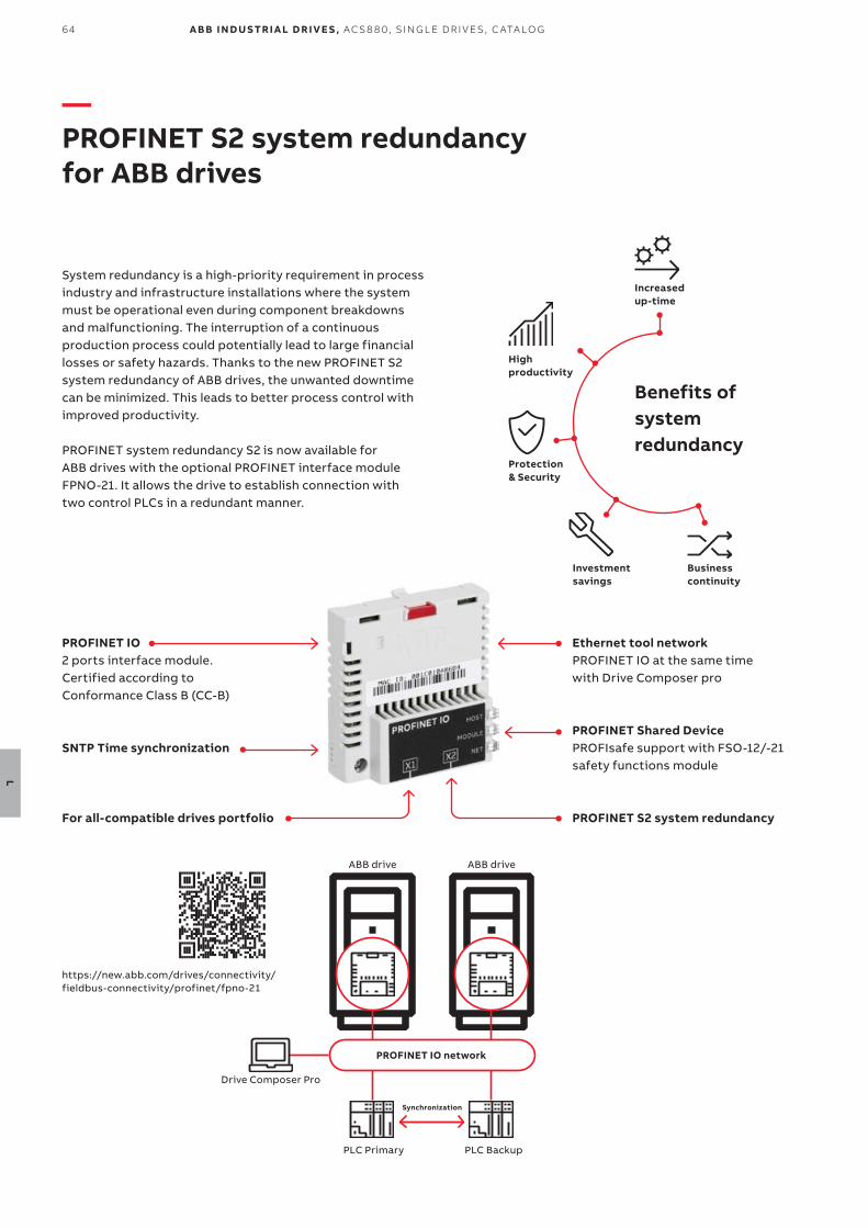
https://new.abb.com/drives/connectivity/fieldbus-connectivity/profinet/fpno-21
64
L
A B B I N D U S TR I A L D R I V E S , AC S 8 8 0, S I N G L E D R I V E S , C ATA LO G
—PROFINET S2 system redundancy for ABB drives
System redundancy is a high-priority requirement in process industry and infrastructure installations where the system must be operational even during component breakdowns and malfunctioning. The interruption of a continuous production process could potentially lead to large financial losses or safety hazards. Thanks to the new PROFINET S2 system redundancy of ABB drives, the unwanted downtime can be minimized. This leads to better process control with improved productivity.
PROFINET system redundancy S2 is now available for ABB drives with the optional PROFINET interface module FPNO-21. It allows the drive to establish connection with two control PLCs in a redundant manner.
Increased up-time
High productivity
Protection & Security
Investment savings
Business continuity
Benefits of system redundancy
PROFINET IO2 ports interface module. Certified according to Conformance Class B (CC-B)
SNTP Time synchronization
For all-compatible drives portfolio
Ethernet tool networkPROFINET IO at the same timewith Drive Composer pro
PROFINET Shared DevicePROFIsafe support with FSO-12/-21 safety functions module
PROFINET S2 system redundancy
PROFINET IO network
PLC Primary PLC Backup
ABB drive ABB drive
Drive Composer Pro
Synchronization
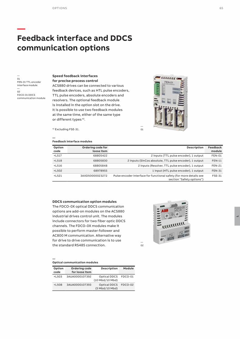
65O P TI O NS
L
—Feedback interface and DDCS communication options
Speed feedback interfaces for precise process controlACS880 drives can be connected to various feedback devices, such as HTL pulse encoders, TTL pulse encoders, absolute encoders and resolvers. The optional feedback module is installed in the option slot on the drive. It is possible to use two feedback modules at the same time, either of the same type or different types *).
*) Excluding FSE-31.
—01 FEN-01 TTL encoder interface module—02 FDCO-01 DDCS communication module
Option code
Ordering code for loose item
Description Feedback module
+L517 68805422 2 inputs (TTL pulse encoder), 1 output FEN-01
+L518 68805830 2 inputs (SinCos absolute, TTL pulse encoder), 1 output FEN-11
+L516 68805848 2 inputs (Resolver, TTL pulse encoder), 1 output FEN-21
+L502 68978955 1 input (HTL pulse encoder), 1 output FEN-31
+L521 3AXD50000023272 Pulse encoder interface for functional safety (for more details see section “Safety options”)
FSE-31
Option code
Ordering code for loose item
Description Module
+L503 3AUA0000107392 Optical DDCS (10 Mbd/10 Mbd)
FDCO-01
+L508 3AUA0000107393 Optical DDCS (5 Mbd/10 Mbd)
FDCO-02
—01
—02
DDCS communication option modulesThe FDCO-0X optical DDCS communication options are add-on modules on the ACS880 industrial drives control unit. The modules include connectors for two fiber optic DDCS channels. The FDCO-0X modules make it possible to perform master-follower and AC800 M communication. Alternative way for drive to drive communication is to use the standard RS485 connection.
—Feedback interface modules
—Optical communication modules

66
L
A B B I N D U S TR I A L D R I V E S , AC S 8 8 0, S I N G L E D R I V E S , C ATA LO G
—ABB Ability™ Digital PowertrainCondition monitoring for drives
Accurate, real-time information about powertrain events. When you have the facts, you can make the right decisions.
ABB Ability™ Digital PowertrainThe ABB Ability™ Digital Powertrain enables you to remotely monitor the health and performance of entire powertrains including drives, motors and applications, such as pumps. The data collected from the connected equipment can be accessed and analyzed remotely, providing a better understanding of the health and energy efficiency of the entire process.
ABB Ability™ Condition Monitoring for drivesABB Ability™ Condition Monitoring for drives is a key element of the Digital Powertrain. The services are designed to provide key information about drive events and changes in behavior to ensure your equipment is always available, reliable and well maintained.
Solid fact-based decision makingGet the facts, and the history, to help run your operations better and more safely.
Always stay one step ahead of problemsRecognize early signs of possible failures and assess the risks, before they turn into serious operational issues.
Find the root cause of process issuesRemotely access data from ABB drives built-in sensors to track the cause of problems. Get back to smooth operation quickly with data back-ups.
Remotely analyze and optimize drivesGet critical drive information anywhere anytime – even in difficult to access sites, or when a site visit is impossible.
The service can be tailored to fit your needs. Our standard package for condition monitoring for drives gives you industry leading monitoring capabilities – whether you want to view the drive status through ABB’s Internet portal or integrate this data with your existing monitoring systems.
The standard package includes the following services:• Condition Monitoring• Alarm Management• Asset Health• Team Support • Backup Management
The standard package can be supplemented with optional services:• Offline Data Collection • Expert Reports • Remote Assistance • Condition monitoring of your
entire powertrain

67O P TI O NS
L1Choose one or more assets you want to protect 2Install the
connectivity device 3Activate access
to the Condition Monitoring basic feature 4Pick optional
features and customize 5Start
monitoring 6Enjoy the customized service
Backup Management
Condition-based Maintenance *)
Offline Data Collection
Remote Assistance
NETA-21
NETA-21 *) Ordering code Description
3AUA0000094517 2 x panel bus interface
max. 9 drives
2 x Ethernet interface
SD memory card
+K496 Connectivity for wired remote monitoring
with NETA-21
+K497 Connectivity for wireless remote monitoring with 4G modem and NETA-21
*) Following optionsavailable for ACS880-07, -17 and -37
—Customers can configure powertrains and customize the digital service plan
Alarm Management
Asset Health
—NETA-21
NETA-21 connects the drive to the cloud via the Internet or local Ethernet network.
The remote data helps you to base your decisions on solid facts and run your operations better and safer.
Remote monitoring helps you to recognize early signs of potential failures and react before a problem occurs. You can also remotely access the data from ABB drives to analyze and find the root cause of a problem.
With remote access you can analyze and optimize drive information anywhere, even in sites that are difficult to access, or when site visit is not possible.
Smart Sensor
*) Not available for all connectivity devices
• The module comes with a built-in web server and requires no Flash/Java plugins
• In the absence of a customer local area network, it can be connected via a mobile network router (either Ethernet or USB network adapter)
• One module can be connected to several drives at the same time
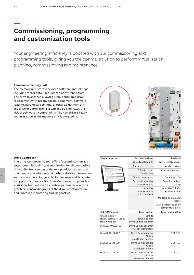
68
L
A B B I N D U S TR I A L D R I V E S , AC S 8 8 0, S I N G L E D R I V E S , C ATA LO G
Removable memory unitThe memory unit stores the drive software and settings, including motor data. This unit can be switched from one drive to another, allowing simple and rapid drive replacement without any special equipment, software loading, parameter settings, or other adjustments in the drive or automation system. It also eliminates the risk of software incompatibility. The new drive is ready to run as soon as the memory unit is plugged in.
Drive Composer Entry level (free) Pro level
Basic functionality Entry-level features
Parameter setting Networked drives
Point-to-point connection
Control diagrams
Simple monitoring Data logger(s)
Supports adaptive programming
Graphical safety setup
Adaptive programming
in Demo mode
Adaptive (block) programming
– Multiple backup and restore
– Drive configuration by using virtual drive
Link/MRP codes Description Type designation
new.abb.com/ drives/software-tools/drive-composer
Link to download free
Drive Composer entry
–
9AKK105408A3415 Drive Composer entry PC tool (document)
–
3AUA0000108087 Drive Composer pro PC tool
(single user license)
DCPT-01
3AUA0000145150 Drive Composer pro PC tool
(10 users license)
DCPT-01
3AUA0000145151 Drive Composer pro PC tool
(20 users license)
DCPT-01
—Commissioning, programming and customization tools
Your engineering efficiency is boosted with our commissioning and programming tools, giving you the optimal solution to perform virtualization, planning, commissioning and maintenance.
Drive ComposerThe Drive Composer PC tool offers fast and harmonized setup, commissioning and monitoring for all-compatible drives. The free version of the tool provides startup and maintenance capabilities and gathers all drive information, such as parameter loggers, faults, backups and lists, into a support diagnostics file. Drive Composer pro provides additional features such as custom parameter windows, graphical control diagrams of the driveʼs configuration, and improved monitoring and diagnostics.
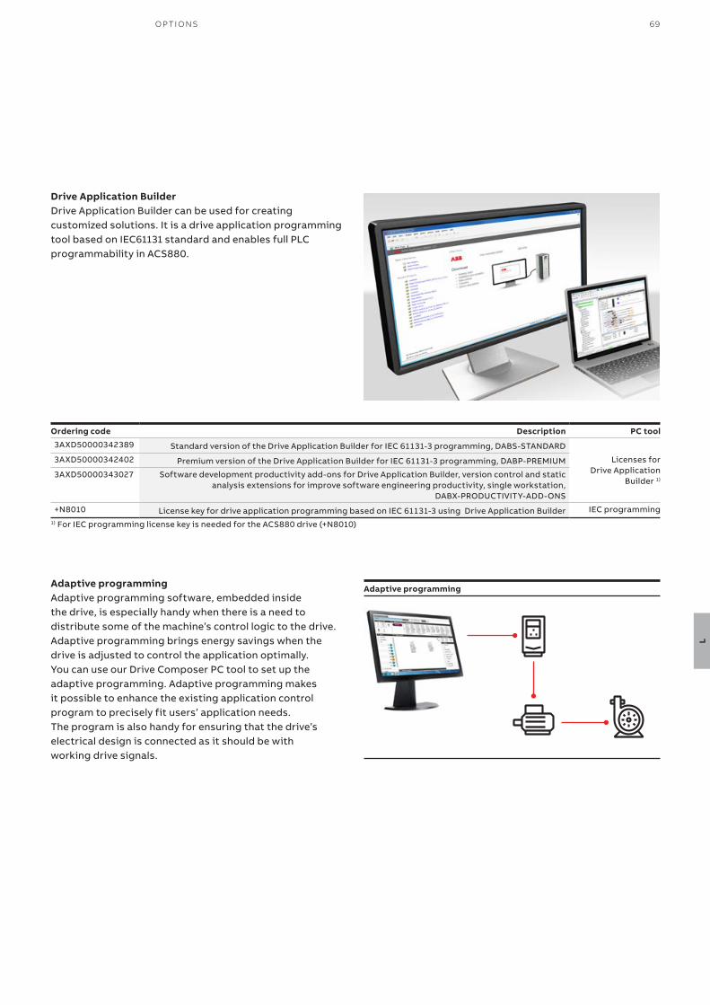
69O P TI O NS
L
Ordering code Description PC tool
3AXD50000342389 Standard version of the Drive Application Builder for IEC 61131-3 programming, DABS-STANDARD
Licenses forDrive Application
Builder 1)
3AXD50000342402 Premium version of the Drive Application Builder for IEC 61131-3 programming, DABP-PREMIUM
3AXD50000343027 Software development productivity add-ons for Drive Application Builder, version control and static analysis extensions for improve software engineering productivity, single workstation,
DABX-PRODUCTIVITY-ADD-ONS
+N8010 License key for drive application programming based on IEC 61131-3 using Drive Application Builder IEC programming1) For IEC programming license key is needed for the ACS880 drive (+N8010)
Adaptive programming
Drive Application BuilderDrive Application Builder can be used for creating customized solutions. It is a drive application programming tool based on IEC61131 standard and enables full PLC programmability in ACS880.
Adaptive programmingAdaptive programming software, embedded inside the drive, is especially handy when there is a need to distribute some of the machine’s control logic to the drive. Adaptive programming brings energy savings when the drive is adjusted to control the application optimally. You can use our Drive Composer PC tool to set up the adaptive programming. Adaptive programming makes it possible to enhance the existing application control program to precisely fit users’ application needs. The program is also handy for ensuring that the drive’s electrical design is connected as it should be with working drive signals.
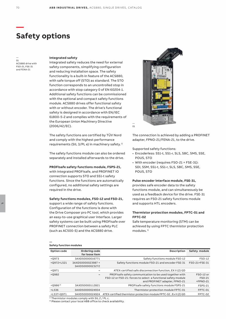
70
L
A B B I N D U S TR I A L D R I V E S , AC S 8 8 0, S I N G L E D R I V E S , C ATA LO G
Option code Ordering code for loose item
Description Safety module
+Q973 3AXD50000016771 Safety functions module FSO-12 FSO-12+Q972+L521 3AXD50000023987 +
3AXD50000023272Safety functions module FSO-21 and encoder FSE-31 FSO-21+FSE-31
+Q971 – ATEX-certified safe disconnection function, EX II (2) GD+Q982 – PROFIsafe safety communication to be used together with
FSO-12 or FSO-21: forces to select a functional safety module and PROFINET adapter, FPNO-21
FSO-12 or FSO-21
+FPNO-21+Q986 2) 3AXD50000112821 PROFIsafe safety functions module FSPS-21 FSPS-21
+L536 3AXD50000024934 Thermistor protection module FPTC-01 FPTC-01
+L537+Q971 3AXD50000024924 ATEX-certified thermistor protection module FPTC-02 , Ex II (2) GD FPTC-02 1) Thermistor modules comply with SIL 2 / PL c. 2) Please contact your local ABB office to check availability.
—Safety function modules
—Safety options
—01 ACS880 drive with FSO-21, FSE-31 and FENA-21
—01
Integrated safetyIntegrated safety reduces the need for external safety components, simplifying configuration and reducing installation space. The safety functionality is a built-in feature of the ACS880, with safe torque off (STO) as standard. The STO function corresponds to an uncontrolled stop in accordance with stop category 0 of EN 60204-1. Additional safety functions can be commissioned with the optional and compact safety functions module. ACS880 drives offer functional safety with or without encoder. The drive’s functional safety is designed in accordance with EN/IEC 61800-5-2 and complies with the requirements of the European Union Machinery Directive (2006/42/EC).
The safety functions are certified by TÜV Nordand comply with the highest performance requirements (SIL 3/PL e) in machinery safety. 1)
The safety functions module can also be ordered separately and installed afterwards to the drive.
PROFIsafe safety functions module, FSPS-21,with integrated PROFIsafe, and PROFINET IO connection supports STO and SS1-t safety functions. Since the functions are automatically configured, no additional safety settings are required in the drive.
Safety functions modules, FSO-12 and FSO-21, support a wide range of safety functions. Configuration of the functions is done with the Drive Composer pro PC tool, which provides an easy-to-use graphical user interface. Larger safety systems can be built using PROFIsafe over PROFINET connection between a safety PLC (such as AC500-S) and the ACS880 drive.
The connection is achieved by adding a PROFINET adapter, FPNO-21/FENA-21, to the drive.
Supported safety functions:• Encoderless: SS1-t, SS1-r, SLS, SBC, SMS, SSE,
POUS, STO• With encoder (requires FSO-21 + FSE-31):
SDI, SSM, SS1-t, SS1-r, SLS, SBC, SMS, SSE, POUS, STO
Pulse encoder interface module, FSE-31,provides safe encoder data to the safety functions module, and can simultaneously be used as a feedback device for the drive. FSE-31 requires an FSO-21 safety functions module and supports HTL encoders.
Thermistor protection modules, FPTC-01 and FPTC-02Safe temperature monitoring (STM) can beachieved by using FPTC thermistor protectionmodules. 1)
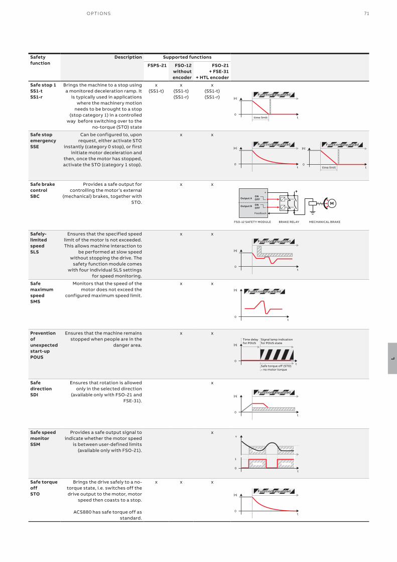
71O P TI O NS
L
Safety function
Description Supported functions
FSPS-21 FSO-12 without encoder
FSO-21 + FSE-31
+ HTL encoder
Safe stop 1 SS1-t SS1-r
Brings the machine to a stop using a monitored deceleration ramp. It
is typically used in applications where the machinery motion
needs to be brought to a stop (stop category 1) in a controlled
way before switching over to the no-torque (STO) state
x(SS1-t)
x(SS1-t)(SS1-r)
x(SS1-t)(SS1-r)
Safe stop emergency SSE
Can be configured to, upon request, either activate STO
instantly (category 0 stop), or first initiate motor deceleration and
then, once the motor has stopped, activate the STO (category 1 stop).
x x
Safe brake control SBC
Provides a safe output for controlling the motor’s external
(mechanical) brakes, together with STO.
x x
Safely-limited speed SLS
Ensures that the specified speed limit of the motor is not exceeded. This allows machine interaction to
be performed at slow speed without stopping the drive. The
safety function module comes with four individual SLS settings
for speed monitoring.
x x
Safe maximum speed SMS
Monitors that the speed of the motor does not exceed the
configured maximum speed limit.
x x
Prevention of unexpected start-up POUS
Ensures that the machine remains stopped when people are in the
danger area.
x x
Safe direction SDI
Ensures that rotation is allowed only in the selected direction
(available only with FSO-21 and FSE-31).
x
Safe speed monitor SSM
Provides a safe output signal to indicate whether the motor speed
is between user-defined limits (available only with FSO-21).
x
Safe torque offSTO
Brings the drive safely to a no-torque state, i.e. switches off the drive output to the motor, motor
speed then coasts to a stop.
ACS880 has safe torque off as standard.
x x x
|n|
0ttime limit
Function requestedFunction requested
|n|
0ttime limit
Function requestedFunction requested|n|
0t
Function requestedFunction requested
FSO-12 SAFETY MODULE BRAKE RELAY MECHANICAL BRAKE
Output A
Output B
ONOFF
ONOFF
M
+
Feedback
+
|n|
0t
Function requestedFunction requested
|n|
0t
Function requestedFunction requested
|n|
0t
Safe torque off (STO)– no motor torque
Signal lamp indicationfor POUS state
Time delayfor POUS
|n|Function requestedFunction requested
0t
v
0t
1
|n|
0t
Function requestedFunction requested
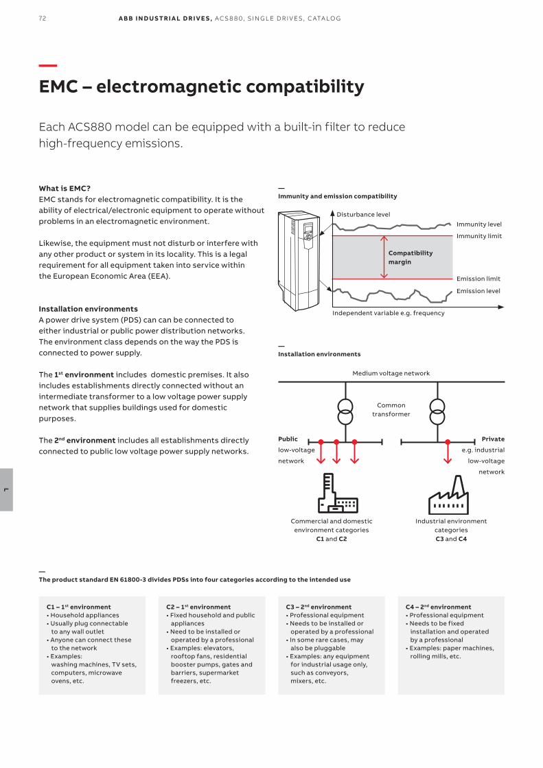
72
L
A B B I N D U S TR I A L D R I V E S , AC S 8 8 0, S I N G L E D R I V E S , C ATA LO G
—EMC – electromagnetic compatibility
Each ACS880 model can be equipped with a built-in filter to reduce high-frequency emissions.
Compatibilitymargin
Independent variable e.g. frequency
Disturbance level
Immunity level
Immunity limit
Emission limit
Emission level
What is EMC?EMC stands for electromagnetic compatibility. It is the ability of electrical/electronic equipment to operate without problems in an electromagnetic environment.
Likewise, the equipment must not disturb or interfere with any other product or system in its locality. This is a legal requirement for all equipment taken into service within the European Economic Area (EEA).
Installation environmentsA power drive system (PDS) can can be connected to either industrial or public power distribution networks. The environment class depends on the way the PDS is connected to power supply.
The 1st environment includes domestic premises. It also includes establishments directly connected without an intermediate transformer to a low voltage power supply network that supplies buildings used for domestic purposes.
The 2nd environment includes all establishments directly connected to public low voltage power supply networks.
—Immunity and emission compatibility
Medium voltage network
Commontransformer
Commercial and domestic environment categories
C1 and C2
Industrial environment categories C3 and C4
Public
low-voltage
network
Private
e.g. industrial
low-voltage
network
—Installation environments
C1 – 1st environment • Household appliances• Usually plug connectable
to any wall outlet• Anyone can connect these
to the network• Examples:
washing machines, TV sets, computers, microwave ovens, etc.
C2 – 1st environment • Fixed household and public
appliances• Need to be installed or
operated by a professional• Examples: elevators,
rooftop fans, residential booster pumps, gates and barriers, supermarket freezers, etc.
C3 – 2nd environment • Professional equipment• Needs to be installed or
operated by a professional• In some rare cases, may
also be pluggable• Examples: any equipment
for industrial usage only, such as conveyors, mixers, etc.
C4 – 2nd environment • Professional equipment• Needs to be fixed
installation and operated by a professional
• Examples: paper machines, rolling mills, etc.
—The product standard EN 61800-3 divides PDSs into four categories according to the intended use
73O P TI O NS
L
Selecting an EMC filter
Drive type Voltage(V)
Frame sizes
1st environment, restricted distribution, C2,
grounded network (TN) Option code
2nd environment, C3,
grounded network
(TN)Option code
2nd environment, C3,
ungrounded network
(IT)Option code
2nd environment, C4,
grounded network (TN) 2)
ACS880-01 208 to 240 R1 to R8 +E202 +E200 +E201 –
ACS880-01 380 to 500 R1 to R9 +E202 +E200 +E201 1) As standard
ACS880-01 525 to 690 R3 to R9 – +E200 +E201 1) As standard
ACS880-11 380 to 500 R3 to R8 +E202 5) +E200 +E201 As standard
ACS880-31 380 to 500 R3 to R8 +E202 5) +E200 +E201 As standard
ACS880-07 380 to 500 R6 to R9 +E202 +E200 +E201 As standard
ACS880-07 525 to 690 R6 to R9 – +E200 +E201 1) As standard
ACS880-07 380 to 500 R10 to R11 +E202 +E200 +E201 As standard
ACS880-07 525 to 690 R10 to R11 – +E200 +E201 As standard
ACS880-07 380 to 690 n×R8i +E202 (only for1140A-3 and 1070A-5)
As standard As standard –
ACS880-17 380 to 500 R8 +E202 +E200 +E201 As standard
ACS880-17 380 to 690 R11 +E202 (not for 690 V) As standard As standard 3) –
ACS880-17 380 to 690 n×R8i +E202 (not for 690 V, only for 1xR8i)
As standard As standard –
ACS880-37 380 to 500 R8 +E202 +E200 +E201 As standard
ACS880-37 380 to 690 R11 +E202 (not for 690 V) As standard As standard 3) –
ACS880-37 380 to 690 n×R8i +E202 (not for 690 V, only for 1xR8i)
As standard As standard –
ACS880-07CLC 525 to 690 n×R8i – As standard 4) As standard 4) As standard
ACS880-17LC 525 to 690 n×R8i – As standard 4) As standard 4) As standard
ACS880-37LC 525 to 690 n×R8i – As standard 4) As standard 4) As standard1) 2nd environment, C4: ACS880-01, 380 to 500 V, frame sizes R1 to R5. ACS880-01, 690 V, frame sizes R3 to R6. ACS880-07, 690 V, frame size R6.2) EMC plan required.3) Please contact your local ABB.4) Radiated emission and immunity (cabinet construction).5) Not available for R6.
Comparison of EMC standards
EN 61800-3,product standard
EN 61800-3, product standard
EN 55011, product family standard for
industrial, scientificand medical (ISM)
equipment
EN 61000-6-4, genericemission standard for
industrial environments
EN 61000-6-3, genericemission standard for
residential, commercialand light-industrial
environments
Category C1 1st environment, unrestricted distribution Group 1. Class B Not applicable Applicable
Category C2 1st environment, restricted distribution Group 1. Class A Applicable Not applicable
Category C3 2nd environment, unrestricted distribution Group 2. Class A Not applicable Not applicable
Category C4 2nd environment, restricted distribution Not applicable Not applicable Not applicable
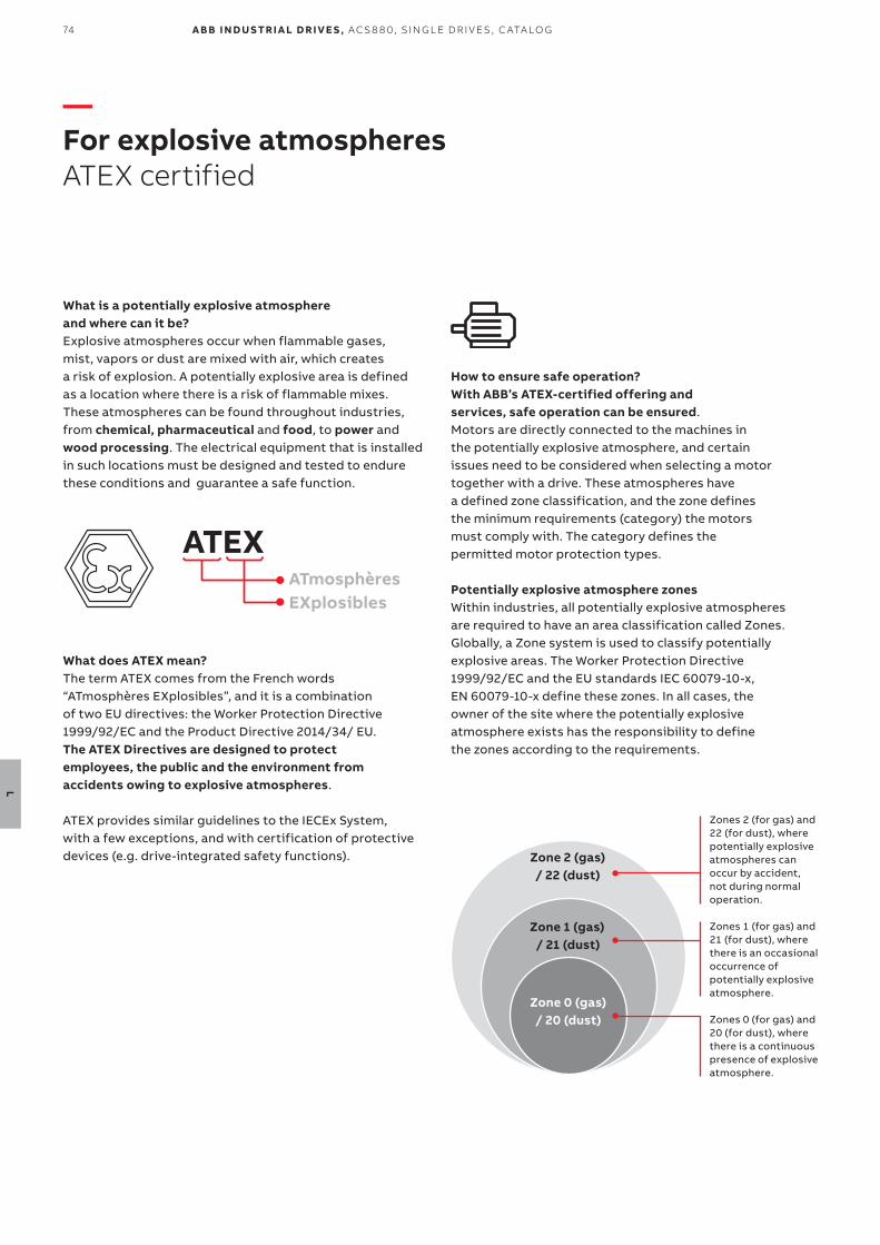
74
L
A B B I N D U S TR I A L D R I V E S , AC S 8 8 0, S I N G L E D R I V E S , C ATA LO G
—For explosive atmospheresATEX certified
What is a potentially explosive atmosphere and where can it be?Explosive atmospheres occur when flammable gases, mist, vapors or dust are mixed with air, which creates a risk of explosion. A potentially explosive area is defined as a location where there is a risk of flammable mixes. These atmospheres can be found throughout industries, from chemical, pharmaceutical and food, to power and wood processing. The electrical equipment that is installed in such locations must be designed and tested to endure these conditions and guarantee a safe function.
ATEXATmosphères EXplosibles
What does ATEX mean?The term ATEX comes from the French words“ATmosphères EXplosibles”, and it is a combination of two EU directives: the Worker Protection Directive 1999/92/EC and the Product Directive 2014/34/ EU. The ATEX Directives are designed to protect employees, the public and the environment from accidents owing to explosive atmospheres.
ATEX provides similar guidelines to the IECEx System, with a few exceptions, and with certification of protective devices (e.g. drive-integrated safety functions).
How to ensure safe operation?With ABB’s ATEX-certified offering and services, safe operation can be ensured. Motors are directly connected to the machines in the potentially explosive atmosphere, and certain issues need to be considered when selecting a motor together with a drive. These atmospheres have a defined zone classification, and the zone defines the minimum requirements (category) the motors must comply with. The category defines the permitted motor protection types.
Potentially explosive atmosphere zonesWithin industries, all potentially explosive atmospheres are required to have an area classification called Zones.Globally, a Zone system is used to classify potentially explosive areas. The Worker Protection Directive 1999/92/EC and the EU standards IEC 60079-10-x, EN 60079-10-x define these zones. In all cases, the owner of the site where the potentially explosive atmosphere exists has the responsibility to define the zones according to the requirements.
Zone 2 (gas) / 22 (dust)
Zone 1 (gas) / 21 (dust)
Zone 0 (gas) / 20 (dust)
Zones 2 (for gas) and 22 (for dust), where potentially explosive atmospheres can occur by accident, not during normal operation.
Zones 1 (for gas) and 21 (for dust), where there is an occasional occurrence of potentially explosive atmosphere.
Zones 0 (for gas) and 20 (for dust), where there is a continuous presence of explosive atmosphere.
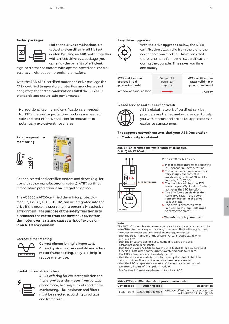
75O P TI O NS
L
Tested packagesMotor and drive combinations are tested and certified in ABB’s test center. By using an ABB motor together with an ABB drive as a package, you can enjoy the benefits of efficient,
high-performance motors with optimal speed and control accuracy – without compromising on safety.
With the ABB ATEX certified motor and drive package the ATEX certified temperature protection modules are not obligatory, the tested combinations fulfill the IEC/ATEX standards and ensure safe performance.
• No additional testing and certification are needed• No ATEX thermistor protection modules are needed• Safe and cost effective solution for industries in
potentially explosive atmospheres
Safe temperature monitoring
For non-tested and certified motors and drives (e.g. for use with other manufacturer's motors), ATEX certified temperature protection is an integrated option.
The ACS880’s ATEX-certified thermistor protection module, Ex II (2) GD, FPTC-02, can be integrated into the drive if the motor is operating in a potentially explosive environment. The purpose of the safety function is to disconnect the motor from the power supply before the motor overheats and causes a risk of explosion in an ATEX environment.
Correct dimensioningCorrect dimensioning is important. Correctly sized motors and drives reduce motor frame heating. They also help to reduce energy use.
Insulation and drive filtersABB’s offering for correct insulation and filters protects the motor from voltage phenomena, bearing currents and motor overheating. The insulation and filters must be selected according to voltage and frame size.
Easy drive upgradesWith the drive upgrades below, the ATEX certification stays valid from the old to the new generation models. This means that there is no need for new ATEX certification during the upgrade. This saves you time and money.
Global service and support networkABB’s global network of certified service providers are trained and experienced to help you with motors and drives for applications in explosive atmospheres.
The support network ensures that your ABB Declaration of Conformity is retained.
ATEX certification approved – old generation model
Comparable converter upgrade
ATEX certification stays valid – new
generation model
ACS600, ACS800, ACS850 ACS880
ABB’s ATEX-certified thermistor protection module, Ex II (2) GD, FPTC-02
With option +L537 +Q971:
1. Motor temperature rises above the PTC sensor limit temperature.
2. The sensor resistance increases very sharply and indicates overheating to the ATEX-certified module, Ex II (2) GD.
3. The module switches the STO (safe torque off) circuit off, which activates the STO function.
4. The STO function disables the control voltage in the power semiconductors of the drive output stage.
5. The drive is prevented from generating the required torque to rotate the motor.
▶ The safe state is guaranteed
Note:The FPTC-02 module can be managed as a loose option and can also be retrofitted to the drive; in this case, to be compliant with regulations, the customer must ensure the following requirements:- that the serial number of the drive/inverter module starts with
1, 4, 7, 8 or Y- that the drive and option serial number is paired in a DIB
(Drive Installed Base) portal- that the included ATEX label for the SMT (Safe Motor Temperature)
function is attached to the drive/inverter module to ensure the ATEX compliance of the safety circuit
- that the option module is installed in an option slot of the drive control unit and the applicable drive parameters are set
- that the PTC temperature sensors of the motor are connected to the PTC inputs of the option module.
* For further information please contact local ABB
Ex Zone
Ex Motor
PTC
STO
FPTC-02 (ACS880)
2.
3-5.
1.
ABB’s ATEX-certified thermistor protection module
Option code Ordering code Description
+L537 +Q971 3AXD50000024924 ATEX-certified thermistor protection module FPTC-02 , Ex II (2) GD
76
L
A B B I N D U S TR I A L D R I V E S , AC S 8 8 0, S I N G L E D R I V E S , C ATA LO G
—Sine filters
Together with a sine filter, ACS880 drives offer smooth motor operation in both DTC and scalar modes. The sine filter suppresses the high-frequency components of the motors output voltage, creating almost a sinusoidal voltage wave form for the motor. The filter offers an optimized LC design that takes into account the switching frequency, voltage drop and filtering characteristics.
The ACS880 inverter and sine filter solution can be used together with a variety of requirements for products and components:• For motors without adequate insulation
for the role• Where the total motor cable length is long as
a result of a number of parallel motors• For step-up applications, e.g. where a
medium voltage motor needs to be driven• For submersible pumps with long motor
cables, e.g. in the oil industry• When the motor noise needs to be reduced• When there are industry-specific requirements
for peak voltage level and voltage rise time
—Sine filter for wall-mounted single drives, ACS880-01
UN = 400 V (range 380 to 415 V). The power ratings are valid at nominal voltage 400 V.
IN PN 1) Noise
level 2)
Heat dissi-
pation 2)
Drive type
Filter type
Degree of protection
Filter width
Filter depth
Filter height
Filter weight
Frame size
(A) (kW) (dB) (W) IP00(mm)
IP21(mm)
IP00 (mm)
IP21 (mm)
IP00 (mm)
IP21 (mm)
IP00 (kg)
IP21 (kg)
2.3 0.75 72 60 ACS880-01-02A4-3 B84143V0004R229 IP00/IP21 235 384 95 152 200 246 5 14.4 R1
3.1 1.1 72 60 ACS880-01-03A3-3 B84143V0004R229 IP00/IP21 235 384 95 152 200 246 5 14.4 R1
3.8 1.5 72 60 ACS880-01-04A0-3 B84143V0004R229 IP00/IP21 235 384 95 152 200 246 5 14.4 R1
5.3 2.2 72 100 ACS880-01-05A6-3 B84143V0006R229 IP00/IP21 235 384 95 152 200 246 5 14.4 R1
7.2 3 72 90 ACS880-01-07A2-3 B84143V0011R229 IP00/IP21 235 384 110 152 200 246 7 14.4 R1
9.2 4 72 90 ACS880-01-09A4-3 B84143V0011R229 IP00/IP21 235 384 110 152 200 246 7 14.4 R1
12.1 5.5 72 80 ACS880-01-12A6-3 B84143V0016R229 IP00/IP21 275 420 122 200 235 290 12 24.4 R1
16 7.5 75 140 ACS880-01-017A-3 B84143V0025R229 IP00/IP21 355 500 120 200 285 360 20 36 R2
24 11 75 140 ACS880-01-025A-3 B84143V0025R229 IP00/IP21 355 500 120 200 285 360 20 36 R2
31 15 75 160 ACS880-01-032A-3 B84143V0033R229 IP00/IP21 355 500 120 200 285 360 24 36 R3
37 18.5 78 220 ACS880-01-038A-3 B84143V0050R229 IP00/IP21 400 650 140 350 360 460 41 90.3 R3
43 22 78 220 ACS880-01-045A-3 B84143V0050R229 IP00/IP21 400 650 140 350 360 460 41 90.3 R4
58 30 78 250 ACS880-01-061A-3 B84143V0066R229 IP00/IP21 400 650 147 350 360 460 43 90.3 R4
64 30 79 310 ACS880-01-072A-3 B84143V0075R229 IP00/IP21 400 650 173 350 360 460 62 90.3 R5
77 37 79 400 ACS880-01-087A-3 B84143V0095R229 IP00/IP21 440 700 164 350 500 580 70 132 R5
91 45 80 600 ACS880-01-105A-3 B84143V0130S230 IP00/IP21 560 850 300 480 420 500 110 192 R6
126 55 80 550 ACS880-01-145A-3 B84143V0162S229 IP00/IP21 500 730 300 400 380 430 112 129.9 R6
153 75 80 550 ACS880-01-169A-3 B84143V0162S229 IP00/IP21 500 730 300 400 380 430 112 129.9 R7
187 90 80 900 ACS880-01-206A-3 B84143V0230S229 IP00/IP21 570 850 285 480 430 500 120 192 R7
209 110 80 900 ACS880-01-246A-3 B84143V0230S229 IP00/IP21 570 850 285 480 430 500 120 192 R8
249 132 80 1570 ACS880-01-293A-3 B84143V0390S229 IP00/IP21 555 850 328 550 580 610 212 268.4 R8
297 160 80 1570 ACS880-01-363A-3 B84143V0390S229 IP00/IP21 555 850 328 550 580 610 212 268.4 R9
352 160 80 1570 ACS880-01-430A-3 B84143V0390S229 IP00/IP21 555 850 328 550 580 610 212 268.4 R9
Nominal ratings
IN Rated current of the drive-filter combination available continuously without overload at 40 °C.
PN Typical motor power1) Please note that sine filters cause a voltage drop, reducing the available shaft power from the motor.2) Noise level is a combined value for the drive and the filter. Heat dissipation is a value for the filter. For further information, please contact your local ABB office.
77O P TI O NS
L
UN = 500 V (range 380 to 500 V). The power ratings are valid at nominal voltage 500 V.
IN PN 1) Noise
level 2)
Heat dissi-
pation 2)
Drive type Filter type Degree of protection
Filter width
Filter depth
Filter height
Filter weight
Frame size
(A) (kW) (dB) (W)IP00
(mm)IP21
(mm)IP00
(mm)IP21
(mm)IP00
(mm)IP21
(mm)IP00 (kg)
IP21(kg)
1.9 0.8 72 60 ACS880-01-02A1-5 B84143V0004R229 IP00/IP21 235 384 95 152 200 246 5 14.4 R1
2.8 1.1 72 60 ACS880-01-03A0-5 B84143V0004R229 IP00/IP21 235 384 95 152 200 246 5 14.4 R1
3.1 1.5 72 60 ACS880-01-03A4-5 B84143V0004R229 IP00/IP21 235 384 95 152 200 246 5 14.4 R1
4.4 2.2 72 100 ACS880-01-04A8-5 B84143V0006R229 IP00/IP21 235 384 95 152 200 246 5 14.4 R1
4.8 3 72 100 ACS880-01-05A2-5 B84143V0006R229 IP00/IP21 235 384 95 152 200 246 5 14.4 R1
7 4 72 90 ACS880-01-07A6-5 B84143V0011R229 IP00/IP21 235 384 110 152 200 246 7 14.4 R1
10.2 5.5 72 90 ACS880-01-11A0-5 B84143V0011R229 IP00/IP21 235 384 110 152 200 246 7 14.4 R1
13 7.5 70 80 ACS880-01-014A-5 B84143V0016R229 IP00/IP21 275 420 122 200 235 290 12 24.4 R2
20 11 75 140 ACS880-01-021A-5 B84143V0025R229 IP00/IP21 355 500 120 200 285 360 20 36 R2
25 15 75 160 ACS880-01-027A-5 B84143V0033R229 IP00/IP21 355 500 120 200 285 360 24 36 R3
32 18.5 78 220 ACS880-01-034A-5 B84143V0050R229 IP00/IP21 400 650 140 350 360 460 41 90.3 R3
35 22 78 220 ACS880-01-040A-5 B84143V0050R229 IP00/IP21 400 650 140 350 360 460 41 90.3 R4
44 30 78 250 ACS880-01-052A-5 B84143V0066R229 IP00/IP21 400 650 147 350 360 460 43 90.3 R4
52 37 78 250 ACS880-01-065A-5 B84143V0066R229 IP00/IP21 400 650 147 350 360 460 43 90.3 R5
61 37 78 310 ACS880-01-077A-5 B84143V0075R229 IP00/IP21 400 650 173 350 360 460 62 132 R5
80 55 80 630 ACS880-01-096A-5 B84143V0130S230 IP00/IP21 565 850 300 480 420 500 110 192 R6
104 55 80 630 ACS880-01-124A-5 B84143V0130S230 IP00/IP21 565 850 300 480 420 500 110 192 R6
140 90 80 550 ACS880-01-156A-5 B84143V0162S229 IP00/IP21 500 730 300 400 380 430 112 129.9 R7
161 110 80 550 ACS880-01-180A-5 B84143V0162S229 IP00/IP21 500 730 300 400 380 430 112 129.9 R7
205 132 80 900 ACS880-01-240A-5 B84143V0230S229 IP00/IP21 570 850 285 480 430 500 120 192 R8
221 132 80 900 ACS880-01-260A-5 B84143V0230S229 IP00/IP21 570 850 285 480 430 500 120 192 R8
289 200 80 1570 ACS880-01-361A-5 B84143V0390S229 IP00/IP21 555 850 328 550 580 610 212 268.4 R9
332 200 80 1570 ACS880-01-414A-5 B84143V0390S229 IP00/IP21 555 850 328 550 580 610 212 268.4 R9
UN = 690 V (range 525 to 690 V). The power ratings are valid at nominal voltage 690 V.
IN PN 1) Noise
level 2)
Heat dissi-
pation 2)
Drive type Filter type Degree of protection
Filter width
Filter depth
Filter height
Filter weight
Frame size
(A) (kW) (dB) (W)IP00
(mm)IP21
(mm)IP00
(mm)IP21
(mm)IP00
(mm)IP21
(mm)IP00 (kg)
IP21 (kg)
7.3 5.5 72 90 ACS880-01-07A4-7 B84143V0010R230 IP00/IP21 380 500 110 200 290 360 15 36 R3
9.3 7.5 72 90 ACS880-01-09A9-7 B84143V0010R230 IP00/IP21 380 500 110 200 290 360 15 36 R3
13.5 11 72 130 ACS880-01-14A3-7 B84143V0018R230 IP00/IP21 380 500 121 200 290 360 19 36 R3
17.1 15 72 130 ACS880-01-019A-7 B84143V0018R230 IP00/IP21 380 500 121 200 290 360 19 36 R3
21 18.5 72 160 ACS880-01-023A-7 B84143V0026R230 IP00/IP21 380 500 141 200 290 360 30 68 R3
25 22 72 160 ACS880-01-027A-7 B84143V0026R230 IP00/IP21 380 500 141 200 290 360 30 68 R3
33 30 75 250 ACS880-01-035A-7 B84143V0040R230 IP00/IP21 440 650 147 350 355 430 49 90.3 R5
40 37 75 250 ACS880-01-042A-7 B84143V0040R230 IP00/IP21 440 650 147 350 355 430 49 90.3 R5
48 45 78 290 ACS880-01-049A-7 B84143V0056R230 IP00/IP21 440 650 162 350 355 430 52 90.3 R5
56 55 78 290 ACS880-01-061A-7 B84143V0056R230 IP00/IP21 440 600 162 350 355 430 52 90.3 R6
78 75 79 610 ACS880-01-084A-7 B84143V0092R230 IP00/IP21 500 700 193 350 490 580 85 132 R6
92 90 79 610 ACS880-01-098A-7 B84143V0092R230 IP00/IP21 500 700 193 350 490 580 85 132 R7
112 110 80 630 ACS880-01-119A-7 B84143V0130S230 IP00/IP21 565 850 300 480 420 500 110 192 R7
112 110 80 630 ACS880-01-142A-7 B84143V0130S230 IP00/IP21 560 850 230 480 569 500 110 192 R8
138 132 80 930 ACS880-01-174A-7 B84143V0207S230 IP00/IP21 560 850 279 550 570 610 185 268.4 R8
161 132 80 930 ACS880-01-210A-7 B84143V0207S230 IP00/IP21 560 850 279 550 570 610 185 268.4 R9
208 200 80 930 ACS880-01-271A-7 B84143V0207S230 IP00/IP21 560 850 279 550 570 610 185 268.4 R9

78
L
A B B I N D U S TR I A L D R I V E S , AC S 8 8 0, S I N G L E D R I V E S , C ATA LO G
Nominal ratings
IN Rated current of the drive-filter combination available continuously without overload at 40 °C.
PN Typical motor power1) Please note that sine filters cause a voltage drop, reducing the available shaft power from the motor.2) Noise level is a combined value for the drive and the filter. Heat dissipation is a value for the filter. For further information please contact your local ABB office.
UN = 400 V (range 380 to 415 V). The power ratings are valid at nominal voltage 400 V.
IN PN 1) Noise
level 2)
Heat dissi-
pation 2)
Drive type Filter type Degree of protection
Filter width
Filter depth
Filter height
Filter weight
Frame size
(A) (kW) (dB) (W) IP00(mm)
IP21(mm)
IP00 (mm)
IP21 (mm)
IP00 (mm)
IP21 (mm)
IP00 (kg)
IP21 (kg)
9.2 4 72 90 ACS880-11/31-09A4-3 B84143V0011R229 IP00/IP21 235 384 110 152 200 246 5.2 14.4 R3
12.1 5.5 72 80 ACS880-11/31-12A6-3 B84143V0016R229 IP00/IP21 275 420 122 200 235 290 7.9 24.4 R3
16 7.5 75 140 ACS880-11/31-017A-3 B84143V0025R229 IP00/IP21 355 500 120 200 285 360 12.1 36 R3
24 11 75 140 ACS880-11/31-025A-3 B84143V0025R229 IP00/IP21 355 500 120 200 285 360 12.1 36 R3
31 15 75 160 ACS880-11/31-032A-3 B84143V0033R229 IP00/IP21 355 500 120 200 285 360 12.1 36 R6
37 18.5 78 220 ACS880-11/31-038A-3 B84143V0050R229 IP00/IP21 400 650 140 350 360 460 20.2 104.7 R6
43 22 78 220 ACS880-11/31-045A-3 B84143V0050R229 IP00/IP21 400 650 140 350 360 460 20.2 104.7 R6
58 30 78 250 ACS880-11/31-061A-3 B84143V0066R229 IP00/IP21 400 650 147 350 360 460 21.2 104.7 R6
64 37 79 310 ACS880-11/31-072A-3 B84143V0075R229 IP00/IP21 400 650 173 350 360 460 24.9 104.7 R6
77 45 79 400 ACS880-11/31-087A-3 B84143V0095R229 IP00/IP21 440 700 164 350 500 580 36.1 142.1 R6
91 55 80 600 ACS880-11/31-105A-3 B84143V0130S230 IP00/IP21 565 850 300 480 420 500 71.2 204 R8
126 75 80 550 ACS880-11/31-145A-3 B84143V0162S229 IP00/IP21 500 730 300 400 380 430 57 125.6 R8
153 90 80 550 ACS880-11/31-169A-3 B84143V0162S229 IP00/IP21 500 730 300 400 380 430 57 125.6 R8
187 110 80 900 ACS880-11/31-206A-3 B84143V0230S229 IP00/IP21 570 850 285 480 430 500 69.9 204 R8
—Sine filters for wall-mounted regenerative and ultra-low harmonic drives, ACS880-11 and ACS880-31
UN = 500 V (range 380 to 500 V). The power ratings are valid at nominal voltage 500 V.
IN PN 1) Noise
level 2)
Heat dissi-
pation 2)
Drive type Filter type Degree of protection
Filter width
Filter depth
Filter height
Filter weight
Frame size
(A) (kW) (dB) (W)IP00
(mm)IP21
(mm)IP00
(mm)IP21
(mm)IP00
(mm)IP21
(mm)IP00 (kg)
IP21(kg)
7 4 72 90 ACS880-11/31-07A6-5 B84143V0011R229 IP00/IP21 235 384 110 152 200 246 5.2 14.4 R3
10.2 5.5 72 90 ACS880-11/31-11A0-5 B84143V0011R229 IP00/IP21 235 384 110 152 200 246 5.2 14.4 R3
13 75 70 80 ACS880-11/31-014A-5 B84143V0016R229 IP00/IP21 275 420 122 200 235 290 7.9 24.4 R3
20 11 75 140 ACS880-11/31-021A-5 B84143V0025R229 IP00/IP21 355 500 120 200 285 360 12.1 36 R3
25 15 75 160 ACS880-11/31-027A-5 B84143V0033R229 IP00/IP21 355 500 120 200 285 360 12.1 36 R6
32 18.5 78 220 ACS880-11/31-034A-5 B84143V0050R229 IP00/IP21 400 650 140 350 360 460 20.2 104.7 R6
35 22 78 220 ACS880-11/31-040A-5 B84143V0050R229 IP00/IP21 400 650 140 350 360 460 20.2 104.7 R6
44 30 78 250 ACS880-11/31-052A-5 B84143V0066R229 IP00/IP21 400 650 147 350 360 460 21.2 104.7 R6
52 37 78 250 ACS880-11/31-065A-5 B84143V0066R229 IP00/IP21 400 650 147 350 360 460 21.2 104.7 R6
61 37 78 310 ACS880-11/31-077A-5 B84143V0075R229 IP00/IP21 400 650 173 350 360 460 24.9 104.7 R6
80 55 80 630 ACS880-11/31-096A-5 B84143V0130S230 IP00/IP21 565 850 300 480 420 500 71.2 204 R8
104 55 80 630 ACS880-11/31-124A-5 B84143V0130S230 IP00/IP21 565 850 300 480 420 500 71.2 204 R8
140 90 80 550 ACS880-11/31-156A-5 B84143V0162S229 IP00/IP21 500 730 300 400 380 430 57 125.6 R8
161 110 80 550 ACS880-11/31-180A-5 B84143V0162S229 IP00/IP21 500 730 300 400 380 430 57 125.6 R8
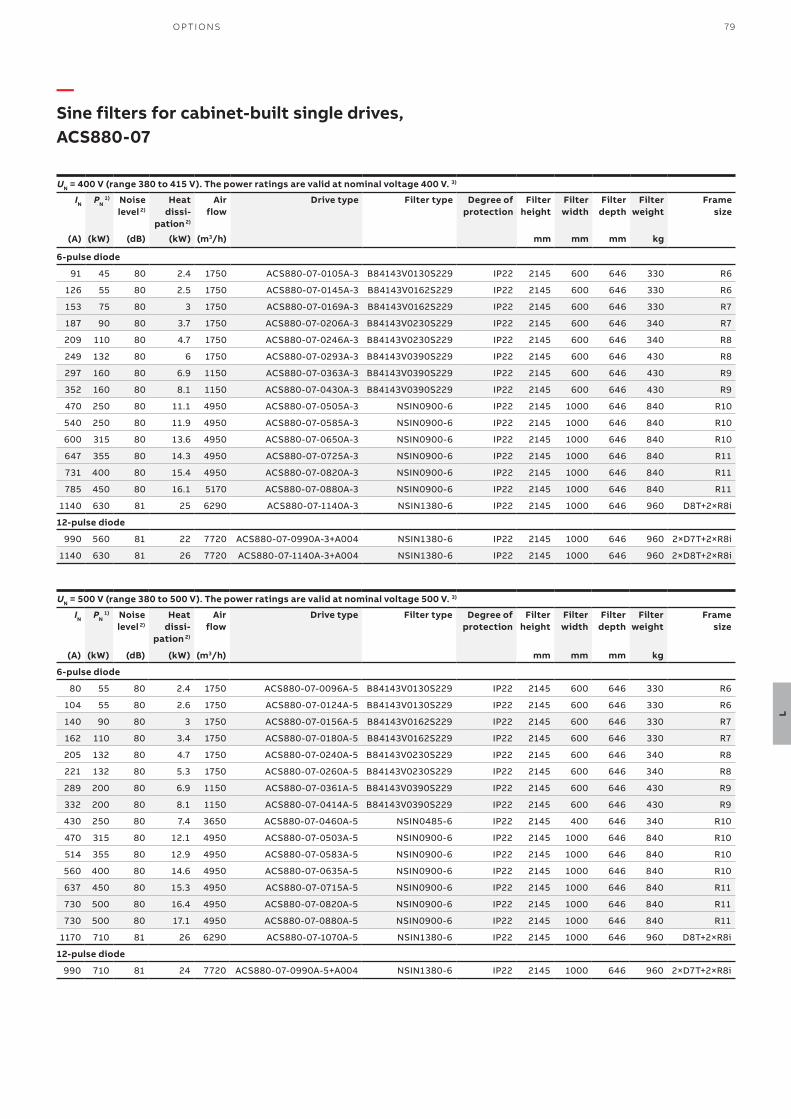
79O P TI O NS
L
UN = 400 V (range 380 to 415 V). The power ratings are valid at nominal voltage 400 V. 3)
IN PN 1) Noise
level 2)
Heat dissi-
pation 2)
Air flow
Drive type Filter type Degree of protection
Filter height
Filter width
Filter depth
Filter weight
Frame size
(A) (kW) (dB) (kW) (m3/h) mm mm mm kg
6-pulse diode
91 45 80 2.4 1750 ACS880-07-0105A-3 B84143V0130S229 IP22 2145 600 646 330 R6
126 55 80 2.5 1750 ACS880-07-0145A-3 B84143V0162S229 IP22 2145 600 646 330 R6
153 75 80 3 1750 ACS880-07-0169A-3 B84143V0162S229 IP22 2145 600 646 330 R7
187 90 80 3.7 1750 ACS880-07-0206A-3 B84143V0230S229 IP22 2145 600 646 340 R7
209 110 80 4.7 1750 ACS880-07-0246A-3 B84143V0230S229 IP22 2145 600 646 340 R8
249 132 80 6 1750 ACS880-07-0293A-3 B84143V0390S229 IP22 2145 600 646 430 R8
297 160 80 6.9 1150 ACS880-07-0363A-3 B84143V0390S229 IP22 2145 600 646 430 R9
352 160 80 8.1 1150 ACS880-07-0430A-3 B84143V0390S229 IP22 2145 600 646 430 R9
470 250 80 11.1 4950 ACS880-07-0505A-3 NSIN0900-6 IP22 2145 1000 646 840 R10
540 250 80 11.9 4950 ACS880-07-0585A-3 NSIN0900-6 IP22 2145 1000 646 840 R10
600 315 80 13.6 4950 ACS880-07-0650A-3 NSIN0900-6 IP22 2145 1000 646 840 R10
647 355 80 14.3 4950 ACS880-07-0725A-3 NSIN0900-6 IP22 2145 1000 646 840 R11
731 400 80 15.4 4950 ACS880-07-0820A-3 NSIN0900-6 IP22 2145 1000 646 840 R11
785 450 80 16.1 5170 ACS880-07-0880A-3 NSIN0900-6 IP22 2145 1000 646 840 R11
1140 630 81 25 6290 ACS880-07-1140A-3 NSIN1380-6 IP22 2145 1000 646 960 D8T+2×R8i
12-pulse diode
990 560 81 22 7720 ACS880-07-0990A-3+A004 NSIN1380-6 IP22 2145 1000 646 960 2×D7T+2×R8i
1140 630 81 26 7720 ACS880-07-1140A-3+A004 NSIN1380-6 IP22 2145 1000 646 960 2×D8T+2×R8i
—Sine filters for cabinet-built single drives, ACS880-07
UN = 500 V (range 380 to 500 V). The power ratings are valid at nominal voltage 500 V. 3)
IN PN 1) Noise
level 2)
Heat dissi-
pation 2)
Air flow
Drive type Filter type Degree of protection
Filter height
Filter width
Filter depth
Filter weight
Frame size
(A) (kW) (dB) (kW) (m3/h) mm mm mm kg
6-pulse diode
80 55 80 2.4 1750 ACS880-07-0096A-5 B84143V0130S229 IP22 2145 600 646 330 R6
104 55 80 2.6 1750 ACS880-07-0124A-5 B84143V0130S229 IP22 2145 600 646 330 R6
140 90 80 3 1750 ACS880-07-0156A-5 B84143V0162S229 IP22 2145 600 646 330 R7
162 110 80 3.4 1750 ACS880-07-0180A-5 B84143V0162S229 IP22 2145 600 646 330 R7
205 132 80 4.7 1750 ACS880-07-0240A-5 B84143V0230S229 IP22 2145 600 646 340 R8
221 132 80 5.3 1750 ACS880-07-0260A-5 B84143V0230S229 IP22 2145 600 646 340 R8
289 200 80 6.9 1150 ACS880-07-0361A-5 B84143V0390S229 IP22 2145 600 646 430 R9
332 200 80 8.1 1150 ACS880-07-0414A-5 B84143V0390S229 IP22 2145 600 646 430 R9
430 250 80 7.4 3650 ACS880-07-0460A-5 NSIN0485-6 IP22 2145 400 646 340 R10
470 315 80 12.1 4950 ACS880-07-0503A-5 NSIN0900-6 IP22 2145 1000 646 840 R10
514 355 80 12.9 4950 ACS880-07-0583A-5 NSIN0900-6 IP22 2145 1000 646 840 R10
560 400 80 14.6 4950 ACS880-07-0635A-5 NSIN0900-6 IP22 2145 1000 646 840 R10
637 450 80 15.3 4950 ACS880-07-0715A-5 NSIN0900-6 IP22 2145 1000 646 840 R11
730 500 80 16.4 4950 ACS880-07-0820A-5 NSIN0900-6 IP22 2145 1000 646 840 R11
730 500 80 17.1 4950 ACS880-07-0880A-5 NSIN0900-6 IP22 2145 1000 646 840 R11
1170 710 81 26 6290 ACS880-07-1070A-5 NSIN1380-6 IP22 2145 1000 646 960 D8T+2×R8i
12-pulse diode
990 710 81 24 7720 ACS880-07-0990A-5+A004 NSIN1380-6 IP22 2145 1000 646 960 2×D7T+2×R8i
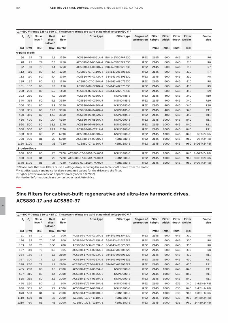
80
L
A B B I N D U S TR I A L D R I V E S , AC S 8 8 0, S I N G L E D R I V E S , C ATA LO G
UN = 690 V (range 525 to 690 V). The power ratings are valid at nominal voltage 690 V. 3)
IN PN 1) Noise
level 2)
Heat dissi-
pation 2)
Air flow
Drive type Filter type Degree of protection
Filter height
Filter width
Filter depth
Filter weight
Frame size
(A) (kW) (dB) (kW) (m3/h) (mm) (mm) (mm) (kg)
6-pulse diode
56 55 78 2.1 1750 ACS880-07-0061A-7 B84143V0056R230 IP22 2145 600 646 280 R6
78 75 79 2.6 1750 ACS880-07-0084A-7 B84143V0092R230 IP22 2145 600 646 310 R6
92 90 79 3.1 1750 ACS880-07-0098A-7 B84143V0092R230 IP22 2145 600 646 310 R7
112 110 80 3.4 1750 ACS880-07-0119A-7 B84143V0130S230 IP22 2145 600 646 330 R7
112 110 80 4.4 1750 ACS880-07-0142A-7 B84143V0130S230 IP22 2145 600 646 330 R8
138 132 80 5.3 1750 ACS880-07-0174A-7 B84143V0207S230 IP22 2145 600 646 410 R8
161 132 80 5.6 1150 ACS880-07-0210A-7 B84143V0207S230 IP22 2145 600 646 410 R9
208 200 80 6.2 1150 ACS880-07-0271A-7 B84143V0207S230 IP22 2145 600 646 410 R9
303 250 80 7.9 3650 ACS880-07-0330A-7 NSIN0485-6 IP22 2145 400 646 340 R10
340 315 80 9.1 3650 ACS880-07-0370A-7 NSIN0485-6 IP22 2145 400 646 340 R10
356 351 80 9.9 3650 ACS880-07-0430A-7 NSIN0485-6 IP22 2145 400 646 340 R10
360 355 80 11.6 3650 ACS880-07-0470A-7 NSIN0485-6 IP22 2145 400 646 340 R11
400 355 80 12.3 3650 ACS880-07-0522A-7 NSIN0485-6 IP22 2145 400 646 340 R11
450 400 80 17.4 4950 ACS880-07-0590A-7 NSIN0900-6 IP22 2145 1000 646 840 R11
550 500 80 18.1 5170 ACS880-07-0650A-7 NSIN0900-6 IP22 2145 1000 646 840 R11
550 500 80 18.1 5170 ACS880-07-0721A-7 NSIN0900-6 IP22 2145 1000 646 840 R11
800 800 80 23 6290 ACS880-07-0800A-7 NSIN0900-6 IP22 2145 1000 646 840 D8T+2×R8i
900 900 81 29 6290 ACS880-07-0900A-7 NSIN1380-6 IP22 2145 1000 646 960 D8T+2×R8i
1160 1100 81 35 7720 ACS880-07-1160A-7 NSIN1380-6 IP22 2145 1000 646 960 2×D8T+2×R8i
12-pulse diode
800 800 80 23 7720 ACS880-07-0800A-7+A004 NSIN0900-6 IP22 2145 1000 646 840 2×D7T+2×R8i
950 900 81 29 7720 ACS880-07-0950A-7+A004 NSIN1380-6 IP22 2145 1000 646 960 2×D8T+2×R8i
1160 1100 81 35 7720 ACS880-07-1160A-7+A004 NSIN1380-6 IP22 2145 1000 646 960 2×D8T+2×R8i1) Please note that sine filters cause a voltage drop, reducing the available shaft power from the motor.2) Heat dissipation and noise level are combined values for the drive and the filter. 3) Higher powers available as application engineered (+P902).For further information please contact your local ABB office.
UN = 400 V (range 380 to 415 V). The power ratings are valid at nominal voltage 400 V. 4)
IN PN 1) Noise
level 2)
Heat dissi-
pation 3)
Air flow
Drive type Filter type Degree of protection
Filter height
Filter width
Filter depth
Filter weight
Frame size
(A) (kW) (dB) (kW) (m3/h) (mm) (mm) (mm) (kg)
91 55 70 0.6 700 ACS880-17/37-0105A-3 B84143V0130R230 IP22 2145 600 646 330 R8
126 75 70 0.55 700 ACS880-17/37-0145A-3 B84143V0162S229 IP22 2145 600 646 330 R8
153 90 70 0.55 700 ACS880-17/37-0169A-3 B84143V0162S229 IP22 2145 600 646 330 R8
187 110 70 0,9 805 ACS880-17/37-0206A-3 B84143V0230S229 IP22 2145 600 646 330 R8
264 160 77 1.6 2100 ACS880-17/37-0293A-3 B84143V0390S229 IP22 2145 600 646 430 R11
327 200 77 1.6 2100 ACS880-17/37-0363A-3 B84143V0390S229 IP22 2145 600 646 430 R11
398 250 77 1.7 2100 ACS880-17/37-0442A-3 B84143V0390S229 IP22 2145 600 646 430 R11
455 250 80 3.0 2000 ACS880-17/37-0505A-3 NSIN0900-6 IP22 2145 1000 646 840 R11
527 315 80 3.4 2000 ACS880-17/37-0585A-3 NSIN0900-6 IP22 2145 1000 646 840 R11
585 355 80 3.8 2000 ACS880-17/37-0650A-3 NSIN0900-6 IP22 2145 1000 646 840 R11
450 250 80 16 700 ACS880-17/37-0450A-3 NSIN0485-6 IP22 2145 400 636 340 1×R8i+1×R8i
620 355 80 22 2000 ACS880-17/37-0620A-3 NSIN0900-6 IP22 2145 1000 636 840 1×R8i+1×R8i
870 500 81 32 2000 ACS880-17/37-0870A-3 NSIN1380-6 IP22 2145 1000 636 960 1×R8i+1×R8i
1110 630 81 38 2000 ACS880-17/37-1110A-3 NSIN1380-6 IP22 2145 1000 636 960 2×R8i+2×R8i
1210 710 81 41 2000 ACS880-17/37-1210A-3 NSIN1380-6 IP22 2145 1000 636 960 2×R8i+2×R8i
—Sine filters for cabinet-built regenerative and ultra-low harmonic drives, ACS880-17 and ACS880-37
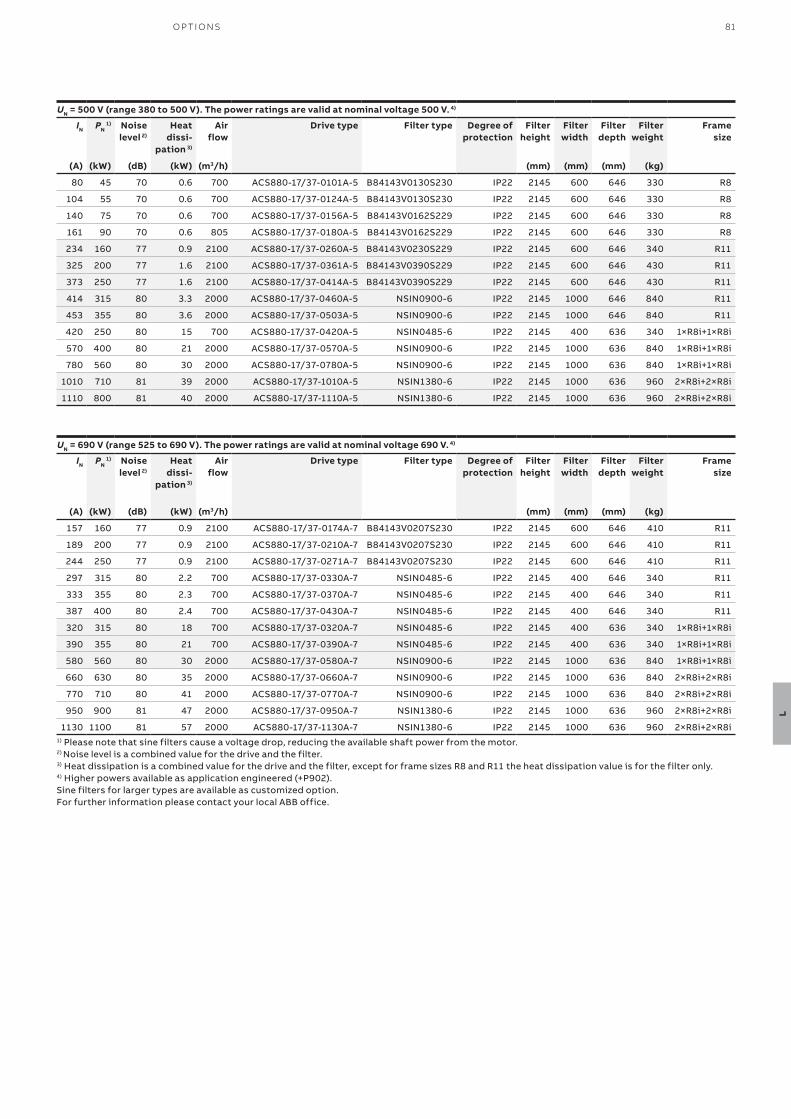
81O P TI O NS
L
UN = 500 V (range 380 to 500 V). The power ratings are valid at nominal voltage 500 V. 4)
IN PN 1) Noise
level 2)
Heat dissi-
pation 3)
Air flow
Drive type Filter type Degree of protection
Filter height
Filter width
Filter depth
Filter weight
Frame size
(A) (kW) (dB) (kW) (m3/h) (mm) (mm) (mm) (kg)
80 45 70 0.6 700 ACS880-17/37-0101A-5 B84143V0130S230 IP22 2145 600 646 330 R8
104 55 70 0.6 700 ACS880-17/37-0124A-5 B84143V0130S230 IP22 2145 600 646 330 R8
140 75 70 0.6 700 ACS880-17/37-0156A-5 B84143V0162S229 IP22 2145 600 646 330 R8
161 90 70 0.6 805 ACS880-17/37-0180A-5 B84143V0162S229 IP22 2145 600 646 330 R8
234 160 77 0.9 2100 ACS880-17/37-0260A-5 B84143V0230S229 IP22 2145 600 646 340 R11
325 200 77 1.6 2100 ACS880-17/37-0361A-5 B84143V0390S229 IP22 2145 600 646 430 R11
373 250 77 1.6 2100 ACS880-17/37-0414A-5 B84143V0390S229 IP22 2145 600 646 430 R11
414 315 80 3.3 2000 ACS880-17/37-0460A-5 NSIN0900-6 IP22 2145 1000 646 840 R11
453 355 80 3.6 2000 ACS880-17/37-0503A-5 NSIN0900-6 IP22 2145 1000 646 840 R11
420 250 80 15 700 ACS880-17/37-0420A-5 NSIN0485-6 IP22 2145 400 636 340 1×R8i+1×R8i
570 400 80 21 2000 ACS880-17/37-0570A-5 NSIN0900-6 IP22 2145 1000 636 840 1×R8i+1×R8i
780 560 80 30 2000 ACS880-17/37-0780A-5 NSIN0900-6 IP22 2145 1000 636 840 1×R8i+1×R8i
1010 710 81 39 2000 ACS880-17/37-1010A-5 NSIN1380-6 IP22 2145 1000 636 960 2×R8i+2×R8i
1110 800 81 40 2000 ACS880-17/37-1110A-5 NSIN1380-6 IP22 2145 1000 636 960 2×R8i+2×R8i
UN = 690 V (range 525 to 690 V). The power ratings are valid at nominal voltage 690 V. 4)
IN PN 1) Noise
level 2)
Heat dissi-
pation 3)
Air flow
Drive type Filter type Degree of protection
Filter height
Filter width
Filter depth
Filter weight
Frame size
(A) (kW) (dB) (kW) (m3/h)
(mm) (mm) (mm) (kg)
157 160 77 0.9 2100 ACS880-17/37-0174A-7 B84143V0207S230 IP22 2145 600 646 410 R11
189 200 77 0.9 2100 ACS880-17/37-0210A-7 B84143V0207S230 IP22 2145 600 646 410 R11
244 250 77 0.9 2100 ACS880-17/37-0271A-7 B84143V0207S230 IP22 2145 600 646 410 R11
297 315 80 2.2 700 ACS880-17/37-0330A-7 NSIN0485-6 IP22 2145 400 646 340 R11
333 355 80 2.3 700 ACS880-17/37-0370A-7 NSIN0485-6 IP22 2145 400 646 340 R11
387 400 80 2.4 700 ACS880-17/37-0430A-7 NSIN0485-6 IP22 2145 400 646 340 R11
320 315 80 18 700 ACS880-17/37-0320A-7 NSIN0485-6 IP22 2145 400 636 340 1×R8i+1×R8i
390 355 80 21 700 ACS880-17/37-0390A-7 NSIN0485-6 IP22 2145 400 636 340 1×R8i+1×R8i
580 560 80 30 2000 ACS880-17/37-0580A-7 NSIN0900-6 IP22 2145 1000 636 840 1×R8i+1×R8i
660 630 80 35 2000 ACS880-17/37-0660A-7 NSIN0900-6 IP22 2145 1000 636 840 2×R8i+2×R8i
770 710 80 41 2000 ACS880-17/37-0770A-7 NSIN0900-6 IP22 2145 1000 636 840 2×R8i+2×R8i
950 900 81 47 2000 ACS880-17/37-0950A-7 NSIN1380-6 IP22 2145 1000 636 960 2×R8i+2×R8i
1130 1100 81 57 2000 ACS880-17/37-1130A-7 NSIN1380-6 IP22 2145 1000 636 960 2×R8i+2×R8i1) Please note that sine filters cause a voltage drop, reducing the available shaft power from the motor.2) Noise level is a combined value for the drive and the filter. 3) Heat dissipation is a combined value for the drive and the filter, except for frame sizes R8 and R11 the heat dissipation value is for the filter only.4) Higher powers available as application engineered (+P902).Sine filters for larger types are available as customized option.For further information please contact your local ABB office.
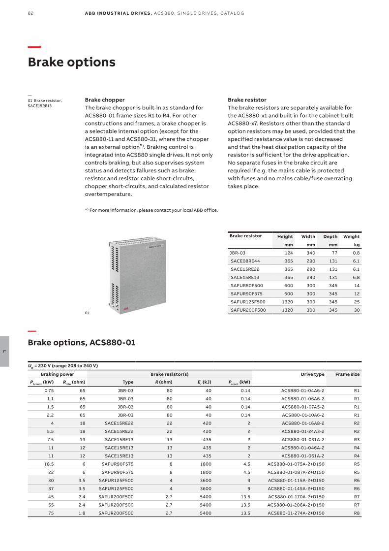
82
L
A B B I N D U S TR I A L D R I V E S , AC S 8 8 0, S I N G L E D R I V E S , C ATA LO G
—Brake options
Brake chopperThe brake chopper is built-in as standard for ACS880-01 frame sizes R1 to R4. For other constructions and frames, a brake chopper is a selectable internal option (except for the ACS880-11 and ACS880-31, where the chopper is an external option* ). Braking control is integrated into ACS880 single drives. It not only controls braking, but also supervises system status and detects failures such as brake resistor and resistor cable short-circuits, chopper short-circuits, and calculated resistor overtemperature.
Brake resistorThe brake resistors are separately available for the ACS880-x1 and built in for the cabinet-built ACS880-x7. Resistors other than the standard option resistors may be used, provided that the specified resistance value is not decreased and that the heat dissipation capacity of the resistor is sufficient for the drive application. No separate fuses in the brake circuit are required if e.g. the mains cable is protected with fuses and no mains cable/fuse overrating takes place.
UN = 230 V (range 208 to 240 V)
Braking power Brake resistor(s) Drive type Frame size
Pbrcont (kW) Rmin (ohm) Type R (ohm) Er (kJ) Prcont (kW)
0.75 65 JBR-03 80 40 0.14 ACS880-01-04A6-2 R1
1.1 65 JBR-03 80 40 0.14 ACS880-01-06A6-2 R1
1.5 65 JBR-03 80 40 0.14 ACS880-01-07A5-2 R1
2.2 65 JBR-03 80 40 0.14 ACS880-01-10A6-2 R1
4 18 SACE15RE22 22 420 2 ACS880-01-16A8-2 R2
5.5 18 SACE15RE22 22 420 2 ACS880-01-24A3-2 R2
7.5 13 SACE15RE13 13 435 2 ACS880-01-031A-2 R3
11 12 SACE15RE13 13 435 2 ACS880-01-046A-2 R4
11 12 SACE15RE13 13 435 2 ACS880-01-061A-2 R4
18.5 6 SAFUR90F575 8 1800 4.5 ACS880-01-075A-2+D150 R5
22 6 SAFUR90F575 8 1800 4.5 ACS880-01-087A-2+D150 R5
30 3.5 SAFUR125F500 4 3600 9 ACS880-01-115A-2+D150 R6
37 3.5 SAFUR125F500 4 3600 9 ACS880-01-145A-2+D150 R6
45 2.4 SAFUR200F500 2.7 5400 13.5 ACS880-01-170A-2+D150 R7
55 2.4 SAFUR200F500 2.7 5400 13.5 ACS880-01-206A-2+D150 R7
75 1.8 SAFUR200F500 2.7 5400 13.5 ACS880-01-274A-2+D150 R8
—Brake options, ACS880-01
Brake resistor Height Width Depth Weight
mm mm mm kg
JBR-03 124 340 77 0.8
SACE08RE44 365 290 131 6.1
SACE15RE22 365 290 131 6.1
SACE15RE13 365 290 131 6.8
SAFUR80F500 600 300 345 14
SAFUR90F575 600 300 345 12
SAFUR125F500 1320 300 345 25
SAFUR200F500 1320 300 345 30
—01 Brake resistor, SACE15RE13
—01
* ) For more information, please contact your local ABB office.
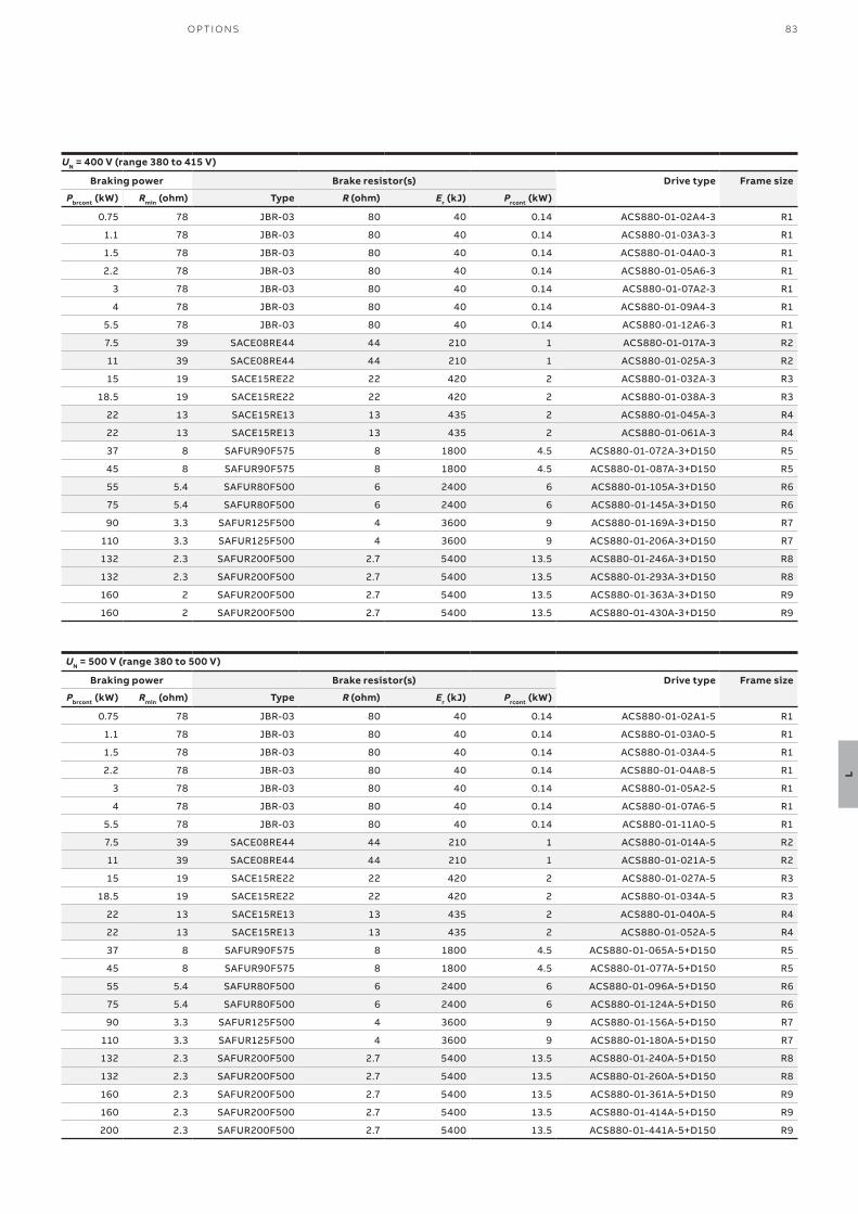
83O P TI O NS
L
UN = 400 V (range 380 to 415 V)
Braking power Brake resistor(s) Drive type Frame size
Pbrcont (kW) Rmin (ohm) Type R (ohm) Er (kJ) Prcont (kW)
0.75 78 JBR-03 80 40 0.14 ACS880-01-02A4-3 R1
1.1 78 JBR-03 80 40 0.14 ACS880-01-03A3-3 R1
1.5 78 JBR-03 80 40 0.14 ACS880-01-04A0-3 R1
2.2 78 JBR-03 80 40 0.14 ACS880-01-05A6-3 R1
3 78 JBR-03 80 40 0.14 ACS880-01-07A2-3 R1
4 78 JBR-03 80 40 0.14 ACS880-01-09A4-3 R1
5.5 78 JBR-03 80 40 0.14 ACS880-01-12A6-3 R1
7.5 39 SACE08RE44 44 210 1 ACS880-01-017A-3 R2
11 39 SACE08RE44 44 210 1 ACS880-01-025A-3 R2
15 19 SACE15RE22 22 420 2 ACS880-01-032A-3 R3
18.5 19 SACE15RE22 22 420 2 ACS880-01-038A-3 R3
22 13 SACE15RE13 13 435 2 ACS880-01-045A-3 R4
22 13 SACE15RE13 13 435 2 ACS880-01-061A-3 R4
37 8 SAFUR90F575 8 1800 4.5 ACS880-01-072A-3+D150 R5
45 8 SAFUR90F575 8 1800 4.5 ACS880-01-087A-3+D150 R5
55 5.4 SAFUR80F500 6 2400 6 ACS880-01-105A-3+D150 R6
75 5.4 SAFUR80F500 6 2400 6 ACS880-01-145A-3+D150 R6
90 3.3 SAFUR125F500 4 3600 9 ACS880-01-169A-3+D150 R7
110 3.3 SAFUR125F500 4 3600 9 ACS880-01-206A-3+D150 R7
132 2.3 SAFUR200F500 2.7 5400 13.5 ACS880-01-246A-3+D150 R8
132 2.3 SAFUR200F500 2.7 5400 13.5 ACS880-01-293A-3+D150 R8
160 2 SAFUR200F500 2.7 5400 13.5 ACS880-01-363A-3+D150 R9
160 2 SAFUR200F500 2.7 5400 13.5 ACS880-01-430A-3+D150 R9
UN = 500 V (range 380 to 500 V)
Braking power Brake resistor(s) Drive type Frame size
Pbrcont (kW) Rmin (ohm) Type R (ohm) Er (kJ) Prcont (kW)
0.75 78 JBR-03 80 40 0.14 ACS880-01-02A1-5 R1
1.1 78 JBR-03 80 40 0.14 ACS880-01-03A0-5 R1
1.5 78 JBR-03 80 40 0.14 ACS880-01-03A4-5 R1
2.2 78 JBR-03 80 40 0.14 ACS880-01-04A8-5 R1
3 78 JBR-03 80 40 0.14 ACS880-01-05A2-5 R1
4 78 JBR-03 80 40 0.14 ACS880-01-07A6-5 R1
5.5 78 JBR-03 80 40 0.14 ACS880-01-11A0-5 R1
7.5 39 SACE08RE44 44 210 1 ACS880-01-014A-5 R2
11 39 SACE08RE44 44 210 1 ACS880-01-021A-5 R2
15 19 SACE15RE22 22 420 2 ACS880-01-027A-5 R3
18.5 19 SACE15RE22 22 420 2 ACS880-01-034A-5 R3
22 13 SACE15RE13 13 435 2 ACS880-01-040A-5 R4
22 13 SACE15RE13 13 435 2 ACS880-01-052A-5 R4
37 8 SAFUR90F575 8 1800 4.5 ACS880-01-065A-5+D150 R5
45 8 SAFUR90F575 8 1800 4.5 ACS880-01-077A-5+D150 R5
55 5.4 SAFUR80F500 6 2400 6 ACS880-01-096A-5+D150 R6
75 5.4 SAFUR80F500 6 2400 6 ACS880-01-124A-5+D150 R6
90 3.3 SAFUR125F500 4 3600 9 ACS880-01-156A-5+D150 R7
110 3.3 SAFUR125F500 4 3600 9 ACS880-01-180A-5+D150 R7
132 2.3 SAFUR200F500 2.7 5400 13.5 ACS880-01-240A-5+D150 R8
132 2.3 SAFUR200F500 2.7 5400 13.5 ACS880-01-260A-5+D150 R8
160 2.3 SAFUR200F500 2.7 5400 13.5 ACS880-01-361A-5+D150 R9
160 2.3 SAFUR200F500 2.7 5400 13.5 ACS880-01-414A-5+D150 R9
200 2.3 SAFUR200F500 2.7 5400 13.5 ACS880-01-441A-5+D150 R9
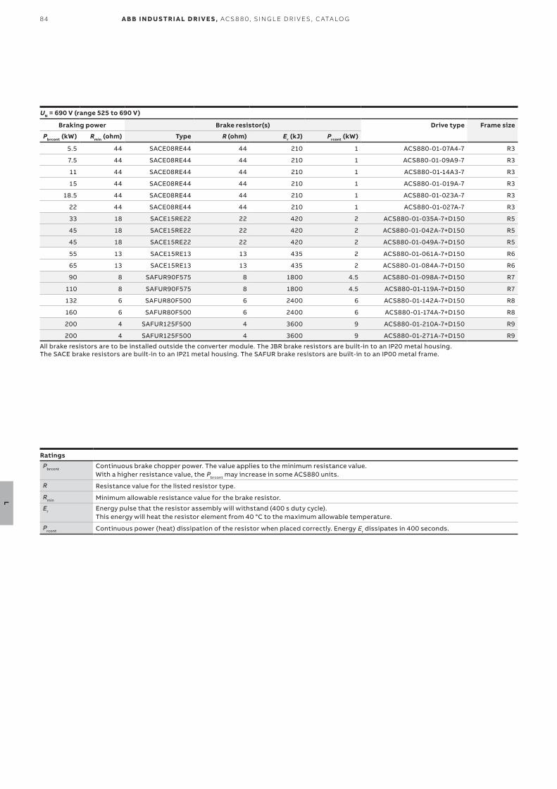
84
L
A B B I N D U S TR I A L D R I V E S , AC S 8 8 0, S I N G L E D R I V E S , C ATA LO G
UN = 690 V (range 525 to 690 V)
Braking power Brake resistor(s) Drive type Frame size
Pbrcont (kW) Rmin (ohm) Type R (ohm) Er (kJ) Prcont (kW)
5.5 44 SACE08RE44 44 210 1 ACS880-01-07A4-7 R3
7.5 44 SACE08RE44 44 210 1 ACS880-01-09A9-7 R3
11 44 SACE08RE44 44 210 1 ACS880-01-14A3-7 R3
15 44 SACE08RE44 44 210 1 ACS880-01-019A-7 R3
18.5 44 SACE08RE44 44 210 1 ACS880-01-023A-7 R3
22 44 SACE08RE44 44 210 1 ACS880-01-027A-7 R3
33 18 SACE15RE22 22 420 2 ACS880-01-035A-7+D150 R5
45 18 SACE15RE22 22 420 2 ACS880-01-042A-7+D150 R5
45 18 SACE15RE22 22 420 2 ACS880-01-049A-7+D150 R5
55 13 SACE15RE13 13 435 2 ACS880-01-061A-7+D150 R6
65 13 SACE15RE13 13 435 2 ACS880-01-084A-7+D150 R6
90 8 SAFUR90F575 8 1800 4.5 ACS880-01-098A-7+D150 R7
110 8 SAFUR90F575 8 1800 4.5 ACS880-01-119A-7+D150 R7
132 6 SAFUR80F500 6 2400 6 ACS880-01-142A-7+D150 R8
160 6 SAFUR80F500 6 2400 6 ACS880-01-174A-7+D150 R8
200 4 SAFUR125F500 4 3600 9 ACS880-01-210A-7+D150 R9
200 4 SAFUR125F500 4 3600 9 ACS880-01-271A-7+D150 R9
All brake resistors are to be installed outside the converter module. The JBR brake resistors are built-in to an IP20 metal housing. The SACE brake resistors are built-in to an IP21 metal housing. The SAFUR brake resistors are built-in to an IP00 metal frame.
Ratings
Pbrcont Continuous brake chopper power. The value applies to the minimum resistance value. With a higher resistance value, the Pbrcont may increase in some ACS880 units.
R Resistance value for the listed resistor type.
Rmin Minimum allowable resistance value for the brake resistor.
Er Energy pulse that the resistor assembly will withstand (400 s duty cycle). This energy will heat the resistor element from 40 °C to the maximum allowable temperature.
Prcont Continuous power (heat) dissipation of the resistor when placed correctly. Energy Er dissipates in 400 seconds.
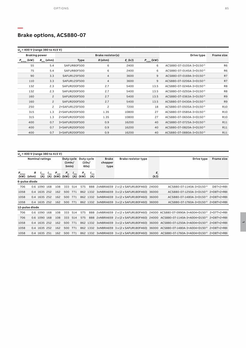
85O P TI O NS
L
—Brake options, ACS880-07
UN = 400 V (range 380 to 415 V)
Braking power Brake resistor(s) Drive type Frame size
Pbrmax (kW) Rmin (ohm) Type R (ohm) Er (kJ) Prcont (kW)
55 5.4 SAFUR80F500 6 2400 6 ACS880-07-0105A-3+D150 2) R6
75 5.4 SAFUR80F500 6 2400 6 ACS880-07-0145A-3+D150 2) R6
90 3.3 SAFUR125F500 4 3600 9 ACS880-07-0169A-3+D150 2) R7
110 3.3 SAFUR125F500 4 3600 9 ACS880-07-0206A-3+D150 2) R7
132 2.3 SAFUR200F500 2.7 5400 13.5 ACS880-07-0246A-3+D150 2) R8
132 2.3 SAFUR200F500 2.7 5400 13.5 ACS880-07-0293A-3+D150 2) R8
160 2 SAFUR200F500 2.7 5400 13.5 ACS880-07-0363A-3+D150 2) R9
160 2 SAFUR200F500 2.7 5400 13.5 ACS880-07-0430A-3+D150 2) R9
250 2 2×SAFUR125F500 2 7200 18 ACS880-07-0505A-3+D150 2) R10
315 1.3 2×SAFUR200F500 1.35 10800 27 ACS880-07-0585A-3+D150 2) R10
315 1.3 2×SAFUR200F500 1.35 10800 27 ACS880-07-0650A-3+D150 2) R10
400 0.7 3×SAFUR200F500 0.9 16200 40 ACS880-07-0725A-3+D150 2) R11
400 0.7 3×SAFUR200F500 0.9 16200 40 ACS880-07-0820A-3+D150 2) R11
400 0.7 3×SAFUR200F500 0.9 16200 40 ACS880-07-0880A-3+D150 2) R11
UN = 400 V (range 380 to 415 V)
Nominal ratings Duty cycle (1min/5min)
Duty cycle (10s/60s)
Brake chopper
type
Brake resistor type Drive type Frame size
Pbrmax (kW)
R (ohm)
Imax (A)
Irms (A)
Pcont (kW)
Pbr (kW)
Irms (A)
Pbr (kW)
Irms (A)
Er (kJ)
6-pulse diode
706 0.6 1090 168 108 333 514 575 888 2xNBRA659 2 x (2 x SAFUR180F460) 24000 ACS880-07-1140A-3+D150 2) D8T+2×R8i
1058 0.4 1635 252 162 500 771 862 1332 3xNBRA659 3 x (2 x SAFUR180F460) 36000 ACS880-07-1250A-3+D150 2) 2×D8T+2×R8i
1058 0.4 1635 252 162 500 771 862 1332 3xNBRA659 3 x (2 x SAFUR180F460) 36000 ACS880-07-1480A-3+D150 2) 2×D8T+2×R8i
1058 0.4 1635 252 162 500 771 862 1332 3xNBRA659 3 x (2 x SAFUR180F460) 36000 ACS880-07-1760A-3+D150 2) 2×D8T+2×R8i
12-pulse diode
706 0.6 1090 168 108 333 514 575 888 2xNBRA659 2 x (2 x SAFUR180F460) 24000 ACS880-07-0990A-3+A004+D150 2) 2×D7T+2×R8i
706 0.6 1090 168 108 333 514 575 888 2xNBRA659 2 x (2 x SAFUR180F460) 24000 ACS880-07-1140A-3+A004+D150 2) 2×D8T+2×R8i
1058 0.4 1635 252 162 500 771 862 1332 3xNBRA659 3 x (2 x SAFUR180F460) 36000 ACS880-07-1250A-3+A004+D150 2) 2×D8T+2×R8i
1058 0.4 1635 252 162 500 771 862 1332 3xNBRA659 3 x (2 x SAFUR180F460) 36000 ACS880-07-1480A-3+A004+D150 2) 2×D8T+2×R8i
1058 0.4 1635 251 162 500 771 862 1332 3xNBRA659 3 x (2 x SAFUR180F460) 36000 ACS880-07-1760A-3+A004+D150 2) 2×D8T+2×R8i
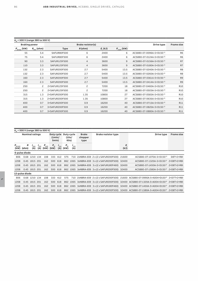
86
L
A B B I N D U S TR I A L D R I V E S , AC S 8 8 0, S I N G L E D R I V E S , C ATA LO G
UN = 500 V (range 380 to 500 V)
Nominal ratings Duty cycle (1min/5min)
Duty cycle (10s/60s)
Brake chopper
type
Brake resistor type Drive type Frame size
Pbrcont (kW)
R (ohm)
Imax (A)
Irms (A)
Pcont (kW)
Pbr (kW)
Irms (A)
Pbr (kW)
Irms (A)
Er (kJ)
6-pulse diode
806 0.68 1210 134 108 333 412 575 710 2xNBRA-659 2 x (2 x SAFUR200F500) 21600 ACS880-07-1070A-5+D150 2) D8T+2×R8i
1208 0.45 1815 201 162 500 618 862 1065 3xNBRA-659 3 x (2 x SAFUR200F500) 32400 ACS880-07-1320A-5+D150 2) 2×D8T+2×R8i
1208 0.45 1815 201 162 500 618 862 1065 3xNBRA-659 3 x (2 x SAFUR180F460) 32400 ACS880-07-1450A-5+D150 2) 2×D8T+2×R8i
1208 0.45 1815 201 162 500 618 862 1065 3xNBRA-659 3 x (2 x SAFUR200F500) 32400 ACS880-07-1580A-5+D150 2) 2×D8T+2×R8i
12-pulse diode
806 0.68 1210 134 108 333 412 575 710 2xNBRA-659 2 x (2 x SAFUR200F500) 21600 ACS880-07-0990A-5+A004+D150 2) 2×D7T+2×R8i
1208 0.45 1815 201 162 500 618 862 1065 3xNBRA-659 3 x (2 x SAFUR200F500) 32400 ACS880-07-1320A-5+A004+D150 2) 2×D8T+2×R8i
1208 0.45 1815 201 162 500 618 862 1065 3xNBRA-659 3 x (2 x SAFUR180F460) 32400 ACS880-07-1450A-5+A004+D150 2) 2×D8T+2×R8i
1208 0.45 1815 201 162 500 618 862 1065 3xNBRA-659 3 x (2 x SAFUR200F500) 32400 ACS880-07-1580A-5+A004+D150 2) 2×D8T+2×R8i
UN = 500 V (range 380 to 500 V)
Braking power Brake resistor(s) Drive type Frame size
Pbrmax (kW) Rmin (ohm) Type R (ohm) Er (kJ) Prcont (kW)
55 5.4 SAFUR80F500 6 2400 6 ACS880-07-0096A-5+D150 2) R6
75 5.4 SAFUR80F500 6 2400 6 ACS880-07-0124A-5+D150 2) R6
90 3.3 SAFUR125F500 4 3600 9 ACS880-07-0156A-5+D150 2) R7
110 3.3 SAFUR125F500 4 3600 9 ACS880-07-0180A-5+D150 2) R7
132 2.3 SAFUR200F500 2.7 5400 13.5 ACS880-07-0240A-5+D150 2) R8
132 2.3 SAFUR200F500 2.7 5400 13.5 ACS880-07-0260A-5+D150 2) R8
160 2.3 SAFUR200F500 2.7 5400 13.5 ACS880-07-0361A-5+D150 2) R9
160 2.3 SAFUR200F500 2.7 5400 13.5 ACS880-07-0414A-5+D150 2) R9
250 2 2×SAFUR125F500 2 7200 18 ACS880-07-0460A-5+D150 2) R10
250 2 2×SAFUR125F500 2 7200 18 ACS880-07-0503A-5+D150 2) R10
315 1.3 2×SAFUR200F500 1.35 10800 27 ACS880-07-0583A-5+D150 2) R10
315 1.3 2×SAFUR200F500 1.35 10800 27 ACS880-07-0635A-5+D150 2) R10
400 0.7 3×SAFUR200F500 0.9 16200 40 ACS880-07-0715A-5+D150 2) R11
400 0.7 3×SAFUR200F500 0.9 16200 40 ACS880-07-0820A-5+D150 2) R11
400 0.7 3×SAFUR200F500 0.9 16200 40 ACS880-07-0880A-5+D150 2) R11
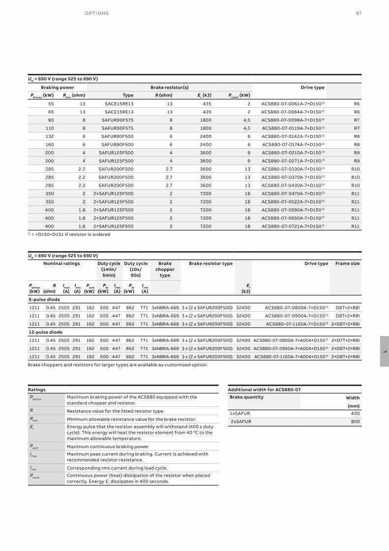
87O P TI O NS
L
UN = 690 V (range 525 to 690 V)
Braking power Brake resistor(s) Drive type
Pbrmax (kW) Rmin (ohm) Type R (ohm) Er (kJ) Prcont (kW)
55 13 SACE15RE13 13 435 2 ACS880-07-0061A-7+D150 2) R6
65 13 SACE15RE13 13 435 2 ACS880-07-0084A-7+D150 2) R6
90 8 SAFUR90F575 8 1800 4,5 ACS880-07-0098A-7+D150 2) R7
110 8 SAFUR90F575 8 1800 4,5 ACS880-07-0119A-7+D150 2) R7
132 6 SAFUR80F500 6 2400 6 ACS880-07-0142A-7+D150 2) R8
160 6 SAFUR80F500 6 2400 6 ACS880-07-0174A-7+D150 2) R8
200 4 SAFUR125F500 4 3600 9 ACS880-07-0210A-7+D150 2) R9
200 4 SAFUR125F500 4 3600 9 ACS880-07-0271A-7+D150 2) R9
285 2.2 SAFUR200F500 2.7 3600 13 ACS880-07-0330A-7+D150 2) R10
285 2.2 SAFUR200F500 2.7 3600 13 ACS880-07-0370A-7+D150 2) R10
285 2.2 SAFUR200F500 2.7 3600 13 ACS880-07-0430A-7+D150 2) R10
350 2 2×SAFUR125F500 2 7200 18 ACS880-07-0470A-7+D150 2) R11
350 2 2×SAFUR125F500 2 7200 18 ACS880-07-0522A-7+D150 2) R11
400 1.8 2×SAFUR125F500 2 7200 18 ACS880-07-0590A-7+D150 2) R11
400 1.8 2×SAFUR125F500 2 7200 18 ACS880-07-0650A-7+D150 2) R11
400 1.8 2×SAFUR125F500 2 7200 18 ACS880-07-0721A-7+D150 2) R112) = +D150+D151 if resistor is ordered
UN = 690 V (range 525 to 690 V)
Nominal ratings Duty cycle (1min/5min)
Duty cycle (10s/60s)
Brake chopper
type
Brake resistor type Drive type Frame size
Pbrmax (kW)
R (ohm)
Imax (A)
Irms (A)
Pcont (kW)
Pbr (kW)
Irms (A)
Pbr (kW)
Irms (A)
Er (kJ)
6-pulse diode
1211 0.45 2505 291 162 500 447 862 771 3xNBRA-669 3 x (2 x SAFUR200F500) 32400 ACS880-07-0800A-7+D150 2) D8T+2×R8i
1211 0.45 2505 291 162 500 447 862 771 3xNBRA-669 3 x (2 x SAFUR200F500) 32400 ACS880-07-0900A-7+D150 2) D8T+2×R8i
1211 0.45 2505 291 162 500 447 862 771 3xNBRA-669 3 x (2 x SAFUR200F500) 32400 ACS880-07-1160A-7+D150 2) 2×D8T+2×R8i
12-pulse diode
1211 0.45 2505 291 162 500 447 862 771 3xNBRA-669 3 x (2 x SAFUR200F500) 32400 ACS880-07-0800A-7+A004+D150 2) 2×D7T+2×R8i
1211 0.45 2505 291 162 500 447 862 771 3xNBRA-669 3 x (2 x SAFUR200F500) 32400 ACS880-07-0950A-7+A004+D150 2) 2×D8T+2×R8i
1211 0.45 2505 291 162 500 447 862 771 3xNBRA-669 3 x (2 x SAFUR200F500) 32400 ACS880-07-1160A-7+A004+D150 2) 2×D8T+2×R8i
Brake choppers and resistors for larger types are available as customized option.
Ratings
Pbrmax Maximum braking power of the ACS880 equipped with the standard chopper and resistor.
R Resistance value for the listed resistor type.
Rmin Minimum allowable resistance value for the brake resistor.
Er Energy pulse that the resistor assembly will withstand (400 s duty cycle). This energy will heat the resistor element from 40 °C to the maximum allowable temperature.
Pcont Maximum continuous braking power
Imax Maximum peak current during braking. Current is achieved with recommended resistor resistance.
Irms Corresponding rms current during load cycle.
Prcont Continuous power (heat) dissipation of the resistor when placed correctly. Energy Er dissipates in 400 seconds.
Additional width for ACS880-07
Brake quantity Width
(mm)
1xSAFUR 400
2xSAFUR 800
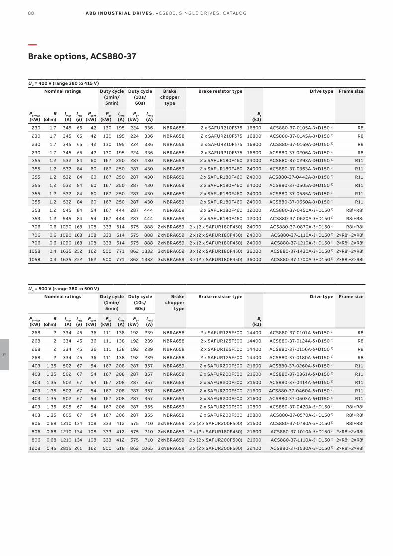
88
L
A B B I N D U S TR I A L D R I V E S , AC S 8 8 0, S I N G L E D R I V E S , C ATA LO G
—Brake options, ACS880-37
UN = 400 V (range 380 to 415 V)
Nominal ratings Duty cycle (1min/5min)
Duty cycle (10s/60s)
Brake chopper
type
Brake resistor type Drive type Frame size
Pbrmax (kW)
R (ohm)
Imax (A)
Irms (A)
Pcont (kW)
Pbr (kW)
Irms (A)
Pbr (kW)
Irms (A)
Er (kJ)
230 1.7 345 65 42 130 195 224 336 NBRA658 2 x SAFUR210F575 16800 ACS880-37-0105A-3+D150 2) R8
230 1.7 345 65 42 130 195 224 336 NBRA658 2 x SAFUR210F575 16800 ACS880-37-0145A-3+D150 2) R8
230 1.7 345 65 42 130 195 224 336 NBRA658 2 x SAFUR210F575 16800 ACS880-37-0169A-3+D150 2) R8
230 1.7 345 65 42 130 195 224 336 NBRA658 2 x SAFUR210F575 16800 ACS880-37-0206A-3+D150 2) R8
355 1.2 532 84 60 167 250 287 430 NBRA659 2 x SAFUR180F460 24000 ACS880-37-0293A-3+D150 2) R11
355 1.2 532 84 60 167 250 287 430 NBRA659 2 x SAFUR180F460 24000 ACS880-37-0363A-3+D150 2) R11
355 1.2 532 84 60 167 250 287 430 NBRA659 2 x SAFUR180F460 24000 ACS880-37-0442A-3+D150 2) R11
355 1,2 532 84 60 167 250 287 430 NBRA659 2 x SAFUR180F460 24000 ACS880-37-0505A-3+D150 2) R11
355 1.2 532 84 60 167 250 287 430 NBRA659 2 x SAFUR180F460 24000 ACS880-37-0585A-3+D150 2) R11
355 1.2 532 84 60 167 250 287 430 NBRA659 2 x SAFUR180F460 24000 ACS880-37-0650A-3+D150 2) R11
353 1.2 545 84 54 167 444 287 444 NBRA659 2 x SAFUR180F460 12000 ACS880-37-0450A-3+D150 2) R8i+R8i
353 1.2 545 84 54 167 444 287 444 NBRA659 2 x SAFUR180F460 12000 ACS880-37-0620A-3+D150 2) R8i+R8i
706 0.6 1090 168 108 333 514 575 888 2xNBRA659 2 x (2 x SAFUR180F460) 24000 ACS880-37-0870A-3+D150 2) R8i+R8i
706 0.6 1090 168 108 333 514 575 888 2xNBRA659 2 x (2 x SAFUR180F460) 24000 ACS880-37-1110A-3+D150 2) 2×R8i+2×R8i
706 0.6 1090 168 108 333 514 575 888 2xNBRA659 2 x (2 x SAFUR180F460) 24000 ACS880-37-1210A-3+D150 2) 2×R8i+2×R8i
1058 0.4 1635 252 162 500 771 862 1332 3xNBRA659 3 x (2 x SAFUR180F460) 36000 ACS880-37-1430A-3+D150 2) 2×R8i+2×R8i
1058 0.4 1635 252 162 500 771 862 1332 3xNBRA659 3 x (2 x SAFUR180F460) 36000 ACS880-37-1700A-3+D150 2) 2×R8i+2×R8i
UN = 500 V (range 380 to 500 V)
Nominal ratings Duty cycle (1min/5min)
Duty cycle (10s/60s)
Brake chopper
type
Brake resistor type Drive type Frame size
Pbrmax (kW)
R (ohm)
Imax (A)
Irms (A)
Pcont (kW)
Pbr (kW)
Irms (A)
Pbr (kW)
Irms (A)
Er (kJ)
268 2 334 45 36 111 138 192 239 NBRA658 2 x SAFUR125F500 14400 ACS880-37-0101A-5+D150 2) R8
268 2 334 45 36 111 138 192 239 NBRA658 2 x SAFUR125F500 14400 ACS880-37-0124A-5+D150 2) R8
268 2 334 45 36 111 138 192 239 NBRA658 2 x SAFUR125F500 14400 ACS880-37-0156A-5+D150 2) R8
268 2 334 45 36 111 138 192 239 NBRA658 2 x SAFUR125F500 14400 ACS880-37-0180A-5+D150 2) R8
403 1.35 502 67 54 167 208 287 357 NBRA659 2 x SAFUR200F500 21600 ACS880-37-0260A-5+D150 2) R11
403 1.35 502 67 54 167 208 287 357 NBRA659 2 x SAFUR200F500 21600 ACS880-37-0361A-5+D150 2) R11
403 1.35 502 67 54 167 208 287 357 NBRA659 2 x SAFUR200F500 21600 ACS880-37-0414A-5+D150 2) R11
403 1.35 502 67 54 167 208 287 357 NBRA659 2 x SAFUR200F500 21600 ACS880-37-0460A-5+D150 2) R11
403 1.35 502 67 54 167 208 287 357 NBRA659 2 x SAFUR200F500 21600 ACS880-37-0503A-5+D150 2) R11
403 1.35 605 67 54 167 206 287 355 NBRA659 2 x SAFUR200F500 10800 ACS880-37-0420A-5+D150 2) R8i+R8i
403 1.35 605 67 54 167 206 287 355 NBRA659 2 x SAFUR200F500 10800 ACS880-37-0570A-5+D150 2) R8i+R8i
806 0.68 1210 134 108 333 412 575 710 2xNBRA659 2 x (2 x SAFUR200F500) 21600 ACS880-37-0780A-5+D150 2) R8i+R8i
806 0.68 1210 134 108 333 412 575 710 2xNBRA659 2 x (2 x SAFUR180F460) 21600 ACS880-37-1010A-5+D150 2) 2×R8i+2×R8i
806 0.68 1210 134 108 333 412 575 710 2xNBRA659 2 x (2 x SAFUR200F500) 21600 ACS880-37-1110A-5+D150 2) 2×R8i+2×R8i
1208 0.45 2815 201 162 500 618 862 1065 3xNBRA659 3 x (2 x SAFUR200F500) 32400 ACS880-37-1530A-5+D150 2) 2×R8i+2×R8i
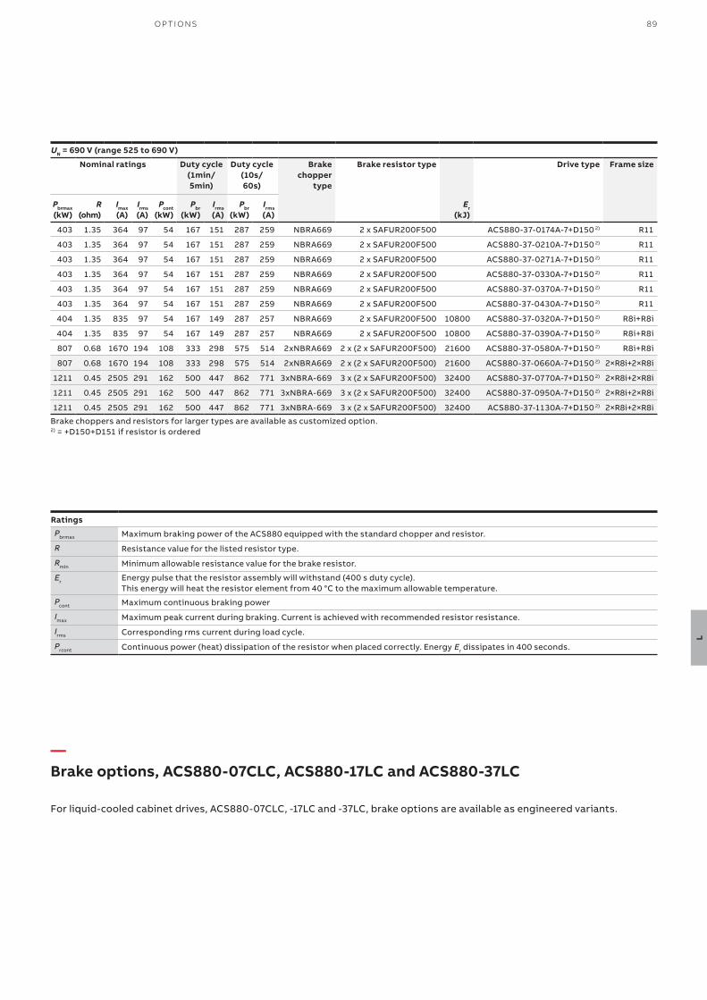
89O P TI O NS
L
UN = 690 V (range 525 to 690 V)
Nominal ratings Duty cycle (1min/5min)
Duty cycle (10s/60s)
Brake chopper
type
Brake resistor type Drive type Frame size
Pbrmax (kW)
R (ohm)
Imax (A)
Irms (A)
Pcont (kW)
Pbr (kW)
Irms (A)
Pbr (kW)
Irms (A)
Er (kJ)
403 1.35 364 97 54 167 151 287 259 NBRA669 2 x SAFUR200F500 ACS880-37-0174A-7+D150 2) R11
403 1.35 364 97 54 167 151 287 259 NBRA669 2 x SAFUR200F500 ACS880-37-0210A-7+D150 2) R11
403 1.35 364 97 54 167 151 287 259 NBRA669 2 x SAFUR200F500 ACS880-37-0271A-7+D150 2) R11
403 1.35 364 97 54 167 151 287 259 NBRA669 2 x SAFUR200F500 ACS880-37-0330A-7+D150 2) R11
403 1.35 364 97 54 167 151 287 259 NBRA669 2 x SAFUR200F500 ACS880-37-0370A-7+D150 2) R11
403 1.35 364 97 54 167 151 287 259 NBRA669 2 x SAFUR200F500 ACS880-37-0430A-7+D150 2) R11
404 1.35 835 97 54 167 149 287 257 NBRA669 2 x SAFUR200F500 10800 ACS880-37-0320A-7+D150 2) R8i+R8i
404 1.35 835 97 54 167 149 287 257 NBRA669 2 x SAFUR200F500 10800 ACS880-37-0390A-7+D150 2) R8i+R8i
807 0.68 1670 194 108 333 298 575 514 2xNBRA669 2 x (2 x SAFUR200F500) 21600 ACS880-37-0580A-7+D150 2) R8i+R8i
807 0.68 1670 194 108 333 298 575 514 2xNBRA669 2 x (2 x SAFUR200F500) 21600 ACS880-37-0660A-7+D150 2) 2×R8i+2×R8i
1211 0.45 2505 291 162 500 447 862 771 3xNBRA-669 3 x (2 x SAFUR200F500) 32400 ACS880-37-0770A-7+D150 2) 2×R8i+2×R8i
1211 0.45 2505 291 162 500 447 862 771 3xNBRA-669 3 x (2 x SAFUR200F500) 32400 ACS880-37-0950A-7+D150 2) 2×R8i+2×R8i
1211 0.45 2505 291 162 500 447 862 771 3xNBRA-669 3 x (2 x SAFUR200F500) 32400 ACS880-37-1130A-7+D150 2) 2×R8i+2×R8i
Brake choppers and resistors for larger types are available as customized option.2) = +D150+D151 if resistor is ordered
Ratings
Pbrmax Maximum braking power of the ACS880 equipped with the standard chopper and resistor.
R Resistance value for the listed resistor type.
Rmin Minimum allowable resistance value for the brake resistor.
Er Energy pulse that the resistor assembly will withstand (400 s duty cycle). This energy will heat the resistor element from 40 °C to the maximum allowable temperature.
Pcont Maximum continuous braking power
Imax Maximum peak current during braking. Current is achieved with recommended resistor resistance.
Irms Corresponding rms current during load cycle.
Prcont Continuous power (heat) dissipation of the resistor when placed correctly. Energy Er dissipates in 400 seconds.
—Brake options, ACS880-07CLC, ACS880-17LC and ACS880-37LC
For liquid-cooled cabinet drives, ACS880-07CLC, -17LC and -37LC, brake options are available as engineered variants.
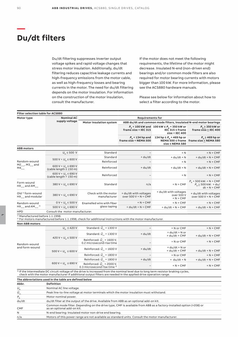
90
L
A B B I N D U S TR I A L D R I V E S , AC S 8 8 0, S I N G L E D R I V E S , C ATA LO G
—Du/dt filters
Du/dt filtering suppresses inverter output voltage spikes and rapid voltage changes that stress motor insulation. Additionally, du/dt filtering reduces capacitive leakage currents and high-frequency emissions from the motor cable, as well as high-frequency losses and bearing currents in the motor. The need for du/dt filtering depends on the motor insulation. For information on the construction of the motor insulation, consult the manufacturer.
If the motor does not meet the following requirements, the lifetime of the motor might decrease. Insulated N-end (non-driven end) bearings and/or common mode filters are also required for motor bearing currents with motors bigger than 100 kW. For more information, please see the ACS880 hardware manuals.
Please see below for information about how to select a filter according to the motor.
Filter selection table for ACS880
Motor type Nominal AC supply voltage
Requirements for
Motor insulation system ABB du/dt and common mode filters, insulated N-end motor bearingsPN < 100 kW and
frame size < IEC 315100 kW ≤ PN < 350 kW or
IEC 315 ≤ frame size < IEC 400
PN > 350 kW orframe size > IEC 400
PN < 134 hp andframe size < NEMA 500
134 hp ≤ PN < 469 hp or NEMA 500 ≤ frame
size ≤ NEMA 580
PN > 469 hp orframe size > NEMA 580
ABB motors
Random-woundM2__, M3__ andM4__
UN ≤ 500 V Standard – + N + N + CMF
500 V < UN ≤ 600 VStandard + du/dt + du/dt + N + du/dt + N + CMF
Reinforced – + N + N + CMF600 V < UN ≤ 690 V
(cable length ≤ 150 m) Reinforced + du/dt + du/dt + N + du/dt + N + CMF
600 V < UN ≤ 690 V(cable length > 150 m) Reinforced – + N + N + CMF
Form-woundHX__ and AM__ 380 V < UN ≤ 690 V Standard n/a + N + CMF
PN < 500 kW: + N + CMFPN > 500 kW: + du/
dt + N + CMF
Old 1) form-woundHX__ and modular 380 V < UN ≤ 690 V Check with the motor
manufacturer+ du/dt with voltages over 500 V + N + CMF
+ du/dt with voltages over 500 V + N + CMF
+ du/dt with voltages over 500 V + N + CMF
Random-woundHX__ and AM__ 2)
0 V < UN ≤ 500 V Enamelled wire with fiber glass taping
+ N + CMF + N + CMF + N + CMF500 V < UN ≤ 690 V + du/dt + N + CMF + du/dt + N + CMF + du/dt + N + CMF
HPD Consult the motor manufacturer.1) Manufactured before 1.1.1998.2) For motors manufactured before 1.1.1998, check for additional instructions with the motor manufacturer.
Non-ABB motors
Random-woundand form-wound
UN ≤ 420 V Standard: ÛLL = 1300 V – + N or CMF + N + CMF
420 V < UN ≤ 500 VStandard: ÛLL = 1300 V + du/dt + du/dt + N or
+ du/dt + CMF + du/dt + N + CMFReinforced: ÛLL = 1600 V,
0.2 microsecond rise time _ + N or CMF + N + CMF
500 V < UN ≤ 600 VReinforced: ÛLL = 1600 V + du/dt + du/dt + N or
+ du/dt + CMF + du/dt + N + CMFReinforced: ÛLL = 1800 V – + N or CMF + N + CMF
600 V < UN ≤ 690 VReinforced: ÛLL = 1800 V + du/dt + du/dt + N + du/dt + N + CMF
Reinforced: ÛLL = 2000 V, 0.3 microsecond rise time 3) – + N + CMF + N + CMF
3) If the intermediate DC circuit voltage of the drive is increased from the nominal level due to long term resistor braking cycles, check with the motor manufacturer if additional output filters are needed in the applied drive operation range.
The abbreviations used in the table are defined belowAbbr. DefinitionUN Nominal AC line voltage.
ÛLL Peak line-to-line voltage at motor terminals which the motor insulation must withstand.
PN Motor nominal power.
du/dt du/dt filter at the output of the drive. Available from ABB as an optional add-on kit.
CMFCommon mode filter. Depending on the drive type, CMF is available from ABB as a factory-installed option (+208) or as an optional add-on kit.
N N-end bearing: insulated motor non-drive end bearing.
n/a Motors of this power range are not available as standard units. Consult the motor manufacturer.
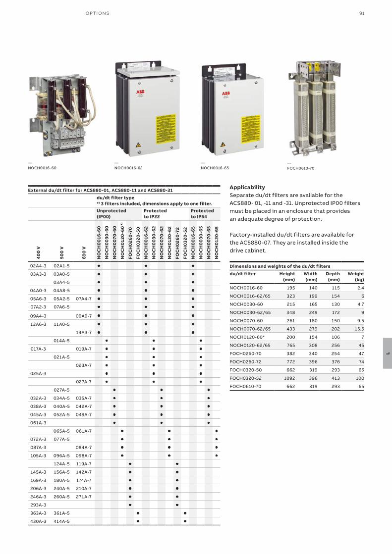
91O P TI O NS
L
External du/dt filter for ACS880-01, ACS880-11 and ACS880-31
du/dt filter type*) 3 filters included, dimensions apply to one filter.Unprotected(IP00)
Protectedto IP22
Protectedto IP54
NO
CH
001
6-6
0
NO
CH
003
0-6
0
NO
CH
007
0-6
0
NO
CH
0120
-60 *)
FOC
H02
60
-70
FOC
H03
20-5
0
NO
CH
001
6-6
2
NO
CH
003
0-6
2
NO
CH
007
0-6
2
NO
CH
0120
-62
FOC
H02
60
-72
FOC
H03
20-5
2
NO
CH
001
6-6
5
NO
CH
003
0-6
5
NO
CH
007
0-6
5
NO
CH
0120
-65
40
0 V
500
V
690
V
02A4-3 02A1-5
03A3-3 03A0-5
03A4-5
04A0-3 04A8-5
05A6-3 05A2-5 07A4-7
07A2-3 07A6-5
09A4-3 09A9-7
12A6-3 11A0-5
14A3-7
014A-5
017A-3 019A-7
021A-5
023A-7
025A-3
027A-7
027A-5
032A-3 034A-5 035A-7
038A-3 040A-5 042A-7
045A-3 052A-5 049A-7
061A-3
065A-5 061A-7
072A-3 077A-5
087A-3 084A-7
105A-3 096A-5 098A-7
124A-5 119A-7
145A-3 156A-5 142A-7
169A-3 180A-5 174A-7
206A-3 240A-5 210A-7
246A-3 260A-5 271A-7
293A-3
363A-3 361A-5
430A-3 414A-5
Dimensions and weights of the du/dt filters
du/dt filter Height (mm)
Width(mm)
Depth(mm)
Weight(kg)
NOCH0016-60 195 140 115 2.4
NOCH0016-62/65 323 199 154 6
NOCH0030-60 215 165 130 4.7
NOCH0030-62/65 348 249 172 9
NOCH0070-60 261 180 150 9.5
NOCH0070-62/65 433 279 202 15.5
NOCH0120-60* 200 154 106 7
NOCH0120-62/65 765 308 256 45
FOCH0260-70 382 340 254 47
FOCH0260-72 772 396 376 74
FOCH0320-50 662 319 293 65
FOCH0320-52 1092 396 413 100
FOCH0610-70 662 319 293 65
ApplicabilitySeparate du/dt filters are available for the ACS880- 01, -11 and -31. Unprotected IP00 filters must be placed in an enclosure that provides an adequate degree of protection.
Factory-installed du/dt filters are available for the ACS880-07. They are installed inside the drive cabinet.
—FOCH0610-70
—NOCH0016-65
—NOCH0016-62
—NOCH0016-60
92 A B B I N D U S TR I A L D R I V E S , AC S 8 8 0, S I N G L E D R I V E S , C ATA LO G
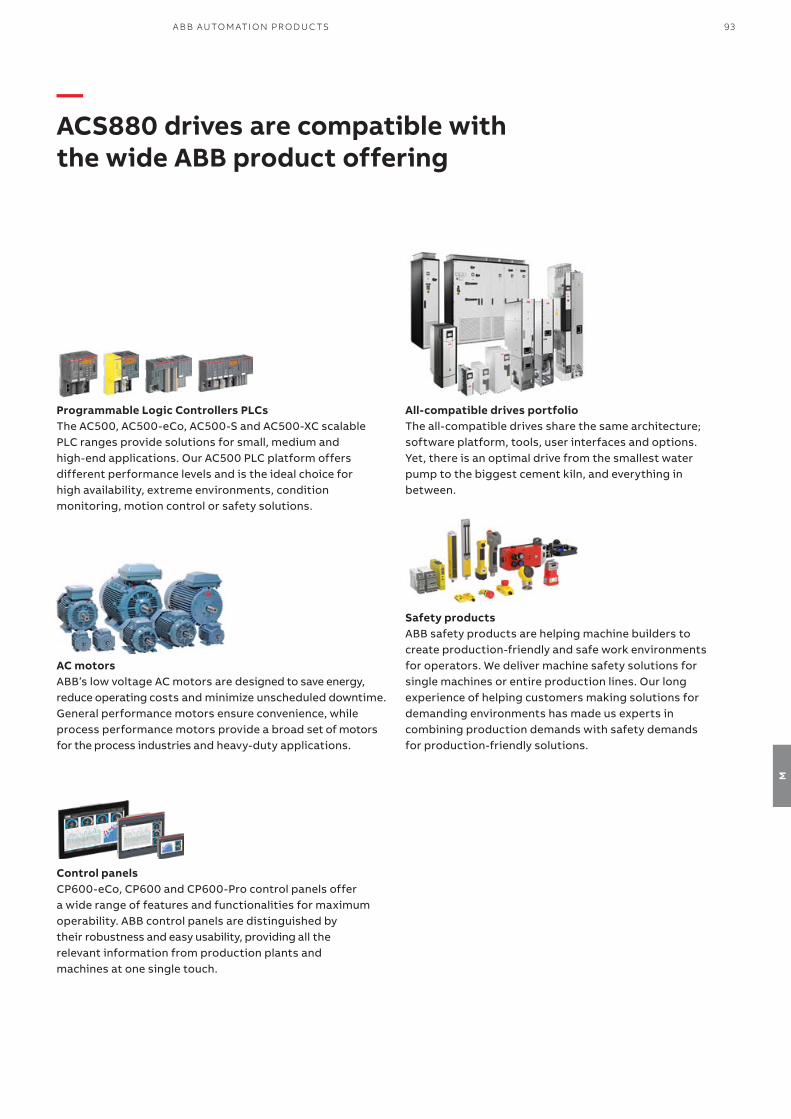
93A B B AU TO M ATI O N PR O D U C TS
M
All-compatible drives portfolioThe all-compatible drives share the same architecture; software platform, tools, user interfaces and options. Yet, there is an optimal drive from the smallest water pump to the biggest cement kiln, and everything in between.
Safety productsABB safety products are helping machine builders to create production-friendly and safe work environments for operators. We deliver machine safety solutions for single machines or entire production lines. Our long experience of helping customers making solutions for demanding environments has made us experts in combining production demands with safety demands for production-friendly solutions.
Programmable Logic Controllers PLCsThe AC500, AC500-eCo, AC500-S and AC500-XC scalable PLC ranges provide solutions for small, medium and high-end applications. Our AC500 PLC platform offers different performance levels and is the ideal choice for high availability, extreme environments, condition monitoring, motion control or safety solutions.
AC motorsABB’s low voltage AC motors are designed to save energy, reduce operating costs and minimize unscheduled downtime. General performance motors ensure convenience, while process performance motors provide a broad set of motors for the process industries and heavy-duty applications.
Control panelsCP600-eCo, CP600 and CP600-Pro control panels offer a wide range of features and functionalities for maximum operability. ABB control panels are distinguished by their robustness and easy usability, providing all the relevant information from production plants and machines at one single touch.
—ACS880 drives are compatible with the wide ABB product offering

94 A B B I N D U S TR I A L D R I V E S , AC S 8 8 0, S I N G L E D R I V E S , C ATA LO G
N
—Choose the right motor for your application
Induction motors and the ACS880: a reliable combinationInduction motors are used throughout industry in applications that demand robust and high enclosure motor and drive solutions. ACS880 drives fit perfectly together with this type of motor by providing comprehensive functionality, yet simple operation. The drives are ideal for environments that require a high degree of protection and small footprint. ACS880 drives come with DTC as standard, ensuring high-speed accuracy. Our motors and drives provide the perfect foundation for energy efficiency, while delivering capabilities such as exceeding the nominal motor speed when maximum power is needed.
Our low voltage motors for explosive atmospheres and low voltage industrial drives have been tested and certified to verify that, when correctly dimensioned, they are safe to use in explosive atmospheres. ABB drives can also be used with non-ABB Ex motors with ATEX-certified thermistor protection. If this protection is not used, the motor and drive combination must be either type-tested or combined-tested for potentially explosive atmospheres by the customer, motor manufacturer or a third party. It is also important to verify that the motor can be used with ABB variable speed drives.
Permanent magnet motors and the ACS880: smooth operationPermanent magnet technology is used for improved motor characteristics in terms of energy efficiency and compactness. This technology is particularly well-suited for low-speed control applications, as in some cases it eliminates the need to use gearboxes. The actual characteristics of different permanent magnet motors can vary considerably. Even without speed or rotor position sensors, ACS880 drives with DTC can control most types of permanent magnet motors.
IE5 synchronous reluctance motors and the ACS880: optimized energy efficiencyCombining the ACS880’s control technology with our synchronous reluctance (SynRM) motors provides an IE5 motor and drive package that ensures high energy efficiency, reduces motor temperatures and provides a significant reduction in motor noise. Lower temperature results in better motor reliability and longer motor life.
ABB has tested our SynRM motor and drive packages and produced manufacturer’s statements providing verified system (drive and motor) efficiency.
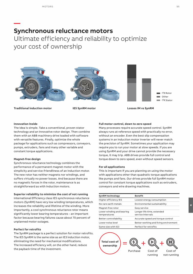
95M OTO R S
N
—Synchronous reluctance motorsUltimate efficiency and reliability to optimize your cost of ownership
Innovation insideThe idea is simple. Take a conventional, proven statortechnology and an innovative rotor design. Then combinethem with an ABB machinery drive loaded with software with versatile features. Finally, optimize the wholepackage for applications such as compressors, conveyors, pumps, extruders, fans and many other variable and constant torque applications.
Magnet-free designSynchronous reluctance technology combines theperformance of a permanent magnet motor with thesimplicity and service-friendliness of an induction motor.The new rotor has neither magnets nor windings, and suffers virtually no power losses. And because there are no magnetic forces in the rotor, maintenance is as straightforward as with induction motors.
Superior reliability to minimize the cost of not running International Efficiency class IE5 synchronous reluctance motors (SynRM) have very low winding temperatures, which increases the reliability and lifetime of the winding. More importantly, a cool synchronous reluctance rotor means significantly lower bearing temperatures – an important factor because bearing failures cause about 70 percent of unplanned motor outages.
Perfect for retrofitsThe SynRM package is a perfect solution for motor retrofits.The IE5 SynRM is the same size as an IE3 induction motor,eliminating the need for mechanical modifications. The increased efficiency will, on the other hand, reduce the payback time of the investment.
Total cost of ownership
Purchase Cost ofrunning
Cost ofnot running
Full motor control, down to zero speedMany processes require accurate speed control. SynRM always runs at reference speed with practically no error, without an encoder. Even the best slip compensation systems in an induction motor inverter will never match the precision of SynRM. Sometimes your application may require you to run your motor at slow speeds. If you are using SynRM and your drive cannot provide the necessary torque, it may trip. ABB drives provide full control and torque down to zero speed, even without speed sensors.
For all applicationsThis is important if you are planning on using the motor with applications other than quadratic torque applications like pumps and fans. Our drives provide full SynRM motor control for constant torque applications such as extruders, conveyors and wire drawing machines.
Traditional induction motor IE5 SynRM motor Losses IM vs SynRM
I²R Rotor
Other
I²R Stator
SynRM technology Benefit
Higher efficiency IE5 Lowest energy consumption
No rare earth metals Environmental sustainability
Magnet-free rotor Easy service
Lower winding and bearingtemperatures
Longer life time, extended service intervals
Better controllability Accurate speed and torque control
Lower noise level Better working and living environment
Same size with IE3 Perfect for retrofits

—Our service expertise, your advantage
ABB Motion Services helps customers around the globe by maximizing uptime, extending product life cycle, and enhancing the performance and energy efficiency of electrical motion solutions. We enable innovation and success through digitalization by securely connecting and monitoring our customers’ motors and drives, increasing operational uptime, and improving efficiency. We make the difference for our customers and partners every day by keeping their operations running profitably, safely and reliably.
With a service offering tailored to your needs, ABB Motion Services maximizes the uptime and extends the life cycle of your electrical motion solutions, while optimizing their performance and maximizing your energy efficiency gains throughout the entire lifetime of your applications. We help to keep your applications turning profitably, safely, and reliably.
Digitalization enables new smart and secured ways to prevent unexpected downtime while optimizing the operation and maintenance of your assets. We securely connect and monitor your motors, drives or your entire powertrain to our easy to use cloud service solutions. Connecting your applications also gives you access to our in-depth service domain expertise.
We quickly respond to your service needs. Together with our partners, local field service experts, and service workshop networks, we provide and install original spare parts to help resolve any issues and minimize the impact of unexpected disruptions.
Our tailored to your needs service offerings and digital solutions will enable you to unlock new possibilities. Not only are we your premier supplier of motion equipment, we are your trusted partner and advisor offering support throughout the entire life cycle of your assets. We ensure your operations run profitably, safely and reliably and continue to drive real world results, now and in the future. Our service teams work with you, delivering the expertise needed to keep your world turning while saving energy every day.
96 A B B I N D U S TR I A L D R I V E S , AC S 8 8 0, S I N G L E D R I V E S , C ATA LO G
O
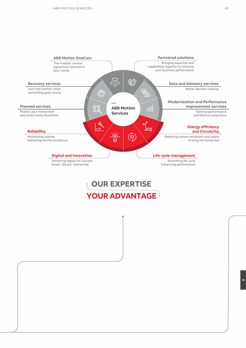
OUR EXPERTISEYOUR ADVANTAGE
—ABB MotionServices
Bringing expertise andcapabilities together to enhance
your business performance
Partnered solutionsThe modular serviceagreement tailored toyour needs
ABB Motion OneCare
Maximizing uptime Delivering service excellence
Reliability
Delivering digital for success Smart. Secure. Connected.
Digital and Innovation
Reducing carbon emissions and wasteDriving the tomorrow
Energy efficiencyand Circularity
Extending life cycleEnhancing performance
Life cycle management
Protect your investmentand avoid costly downtime
Planned services
Fast intervention whensomething goes wrong
Recovery servicesBetter decision making
Data and Advisory services
Optimal performanceand lifetime extensions
Modernization and Performanceimprovement services
97A B B M OTI O N SER V I CE S
O

98 A B B I N D U S TR I A L D R I V E S , AC S 8 8 0, S I N G L E D R I V E S , C ATA LO G
P
—Drivetune mobile application for wireless access
User-friendly experience with Bluetooth connectivity.
Drivetune mobile app is a powerful tool for performing basic drive startup and troubleshooting tasks. It ispossible to connect with drives and access data available in the Internet at the same time. The wireless Bluetooth
connectivity means that users won't need to enter hazardous or difficult-to-reach work areas to accessinformation necessary to help them commission and tune the drive.
Startup, commission and tuneyour drive and applicationwith full parameter access
Optimize performance viadrive troubleshooting features
Create and share backups andsupport packages
Keep track of drives installedbase
ABB Ability™ Mobile Connect for drives is a module in the Drivetune app. It gives you the access to the technical support for fast problem solving. Mobile Connect makes all the necessary data instantly available to the expert, providing support.
Remote and rapid access to ABB’s drive experts can save you and your team considerable time, money and headaches. Check Mobile Connect availability in your country.
Drivewith Bluetooth panel
Mobile devicewith Drivetune app
Expert helpwith Mobile Connect license
Drivetune for commissioning and managing drives
Download Drivetune
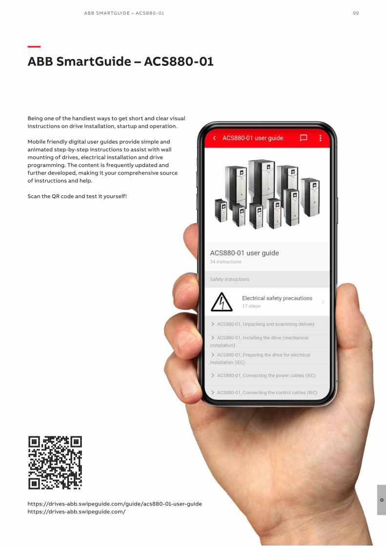
Being one of the handiest ways to get short and clear visual instructions on drive installation, startup and operation.
Mobile friendly digital user guides provide simple and animated step-by-step instructions to assist with wall mounting of drives, electrical installation and drive programming. The content is frequently updated and further developed, making it your comprehensive source of instructions and help.
Scan the QR code and test it yourself!
—ABB SmartGuide – ACS880-01
https://drives-abb.swipeguide.com/guide/acs880-01-user-guidehttps://drives-abb.swipeguide.com/
99A B B SM A RTG U I D E – AC S 8 8 0 - 01
O
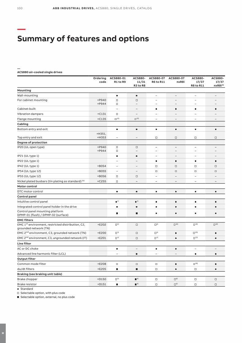
100 A B B I N D U S TR I A L D R I V E S , AC S 8 8 0, S I N G L E D R I V E S , C ATA LO G
R
—Summary of features and options
Ordering code
ACS880-01 R1 to R9
ACS880-11/31
R3 to R8
ACS880-07 R6 to R11
ACS880-07 nxR8i
ACS880-17/37
R8 to R11
ACS880-17/37
nxR8i 8)
Mounting
Wall-mounting – – – –
For cabinet mounting +P940 +P944 –
––
––
––
––
Cabinet-built – –
Vibration dampers +C131 – – – – –
Flange mounting +C135 15) 15) – – – –
Cabling
Bottom entry and exit
Top entry and exit+H351, +H353 – –
Degree of protection
IP20 (UL open type) +P940 +P944
–
––
––
– –
––
IP21 (UL type 1) – – – –
IP22 (UL type 1) – –
IP42 (UL type 1) +B054 – –
IP54 (UL type 12) +B055 – –
IP55 (UL type 12) +B056 – – – –
Nickel plated busbars (tin plating as standard) 30) +C255 – – – – –
Motor control
DTC motor control
Control panel
Intuitive control panel 1) 1)
Integrated control panel holder in the drive
Control panel mounting platform DPMP-01 (flush) / DPMP-02 (surface)
EMC filters
EMC 1st environment, restricted distribution, C2, grounded network (TN)
+E202 2) 2) 16) 19) 22)
EMC 2nd environment, C3, grounded network (TN) +E200 3) 3) 20)
EMC 2nd environment, C3, ungrounded network (IT) +E201 4) 4)
23)
Line filter
AC or DC choke – – –
Advanced line harmonic filter (LCL) – – –
Output filter
Common mode filter +E208 28)
du/dt filters +E205
Braking (see braking unit table)
Brake chopper +D150 5) 8) 6)
Brake resistor +D151 8) 6)
Standard Selectable option, with plus code Selectable option, external, no plus code
—ACS880 air-cooled single drives
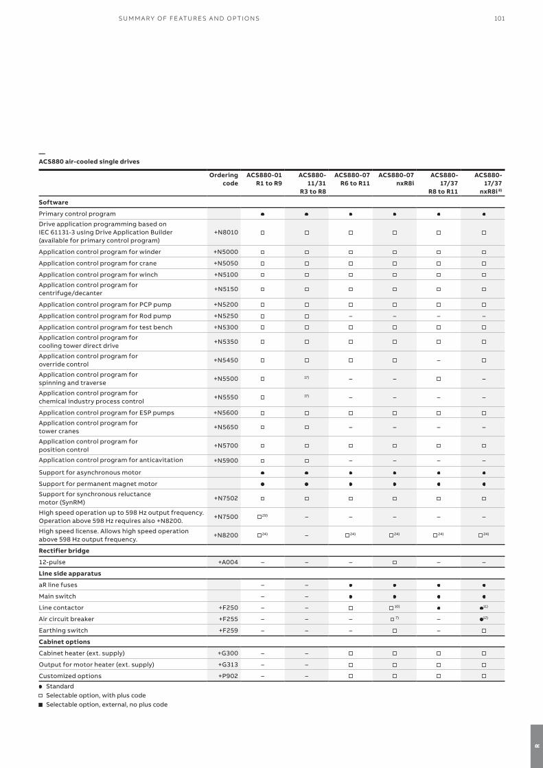
101SU M M A R Y O F FE AT U R E S A N D O P TI O NS
R
Ordering code
ACS880-01 R1 to R9
ACS880-11/31
R3 to R8
ACS880-07 R6 to R11
ACS880-07 nxR8i
ACS880-17/37
R8 to R11
ACS880-17/37
nxR8i 8)
Software
Primary control program
Drive application programming based on IEC 61131-3 using Drive Application Builder(available for primary control program)
+N8010
Application control program for winder +N5000
Application control program for crane +N5050
Application control program for winch +N5100
Application control program for centrifuge/decanter
+N5150
Application control program for PCP pump +N5200
Application control program for Rod pump +N5250 – – – –
Application control program for test bench +N5300
Application control program for cooling tower direct drive
+N5350
Application control program for override control
+N5450 –
Application control program for spinning and traverse
+N5500 17) – – –
Application control program for chemical industry process control
+N5550 17) – – – –
Application control program for ESP pumps +N5600
Application control program for tower cranes
+N5650 – – – –
Application control program forposition control
+N5700
Application control program for anticavitation +N5900 – – – –
Support for asynchronous motor
Support for permanent magnet motor
Support for synchronous reluctance motor (SynRM)
+N7502
High speed operation up to 598 Hz output frequency. Operation above 598 Hz requires also +N8200.
+N7500 29) – – – – –
High speed license. Allows high speed operation above 598 Hz output frequency.
+N8200 24) – 24) 24) 24) 24)
Rectifier bridge
12-pulse +A004 – – – – –
Line side apparatus
aR line fuses – –
Main switch – –
Line contactor +F250 – – 10) 11)
Air circuit breaker +F255 – – – 7) – 12)
Earthing switch +F259 – – – –
Cabinet options
Cabinet heater (ext. supply) +G300 – –
Output for motor heater (ext. supply) +G313 – –
Customized options +P902 – –
Standard Selectable option, with plus code Selectable option, external, no plus code
—ACS880 air-cooled single drives

102 A B B I N D U S TR I A L D R I V E S , AC S 8 8 0, S I N G L E D R I V E S , C ATA LO G
R
Ordering code
ACS880-01 R1 to R9
ACS880-11/31
R3 to R8
ACS880-07 R6 to R11
ACS880-07 nxR8i
ACS880-17/37
R8 to R11
ACS880-17/37
nxR8i 8)
Safety functions 18)
Safe torque off (STO)
Safety functions module, FSO-12, without encoder, configurable functions:
- Safe stop 1 (SS1-t, SS1-r), - Safely-limited speed (SLS) - Safe brake control (SBC) - Safe maximum speed (SMS) - Safe stop emergency (SSE)- Prevention of unexpected start-up (POUS)- Safe torque off (STO)
+Q973
Safety functions module, FSO-21, with encoder support, configurable functions:
- Safe stop 1 (SS1-t, SS1-r) - Safely-limited speed (SLS) - Safe brake control (SBC)- Safe maximum speed (SMS)- Safe stop emergency (SSE)- Prevention of unexpected start-up (POUS)- Safe direction (SDI), requires encoder
feedback, FSE-31- Safe speed monitoring (SSM)- Safe torque off (STO)
+Q972
Pulse encoder interface module, FSE-31 +L521
PROFIsafe over PROFINET +Q982
PROFIsafe safety functions module, FSPS-21 +Q986 8) 8)
Prevention of unexpected start-up with safety relay (preconfigured)
+Q957 – –
Prevention of unexpected start-up with FSO-12 and -21 (preconfigured)
+Q950 – –
Emergency stop, category 0 with opening the main contactor/breaker, with safety relay (preconfigured)
+Q951 – –
Emergency stop, category 1 with opening the main contactor/breaker, with safety relay (preconfigured)
+Q952 – –
Emergency stop, category 0 with STO, with safety relay (preconfigured)
+Q963 – –
Emergency stop, category 1 with STO, with safety relay (preconfigured)
+Q964 – –
Emergency stop, configurable category 0 or 1 with opening the main contactor/breaker, with FSO-12 and -21 (preconfigured)
+Q978 – –
Emergency stop, configurable category 0 or 1 with STO and FSO-12 and -21 (preconfigured)
+Q979 – –
Safely-limited speed with encoder, with FSO-21 and FSE-31 (preconfigured)
+Q965 – –
ATEX certified thermistor protection module, FPTC-02, Ex II (2) GD
+L537 +Q971
ATEX thermal motor protection PTC/PT100, Ex II (2) GD
+L513/+L514 +Q971
– –
Earth fault protection
Earth fault monitoring, earthed mains
Earth fault monitoring, unearthed mains +Q954 – –
Standard Selectable option, with plus code Selectable option, external, no plus code
—ACS880 air-cooled single drives

103SU M M A R Y O F FE AT U R E S A N D O P TI O NS
R
Ordering code
ACS880-01 R1 to R9
ACS880-11/31
R3 to R8
ACS880-07 R6 to R11
ACS880-07 nxR8i
ACS880-17/37
R8 to R11
ACS880-17/37
nxR8i 8)
Control connections (I/O) and communications2 pcs analog inputs, programmable, galvanically isolated
2 pcs analog outputs, programmable6 pcs digital inputs, programmable, galvanically isolated – can be divided into two groups
2 pcs digital inputs/outputs
1 pcs digital input interlock
3 pcs relay outputs programmable
Drive-to-drive link/Built-in Modbus
Assistant control panel/PC tool connectionPossibility for external power supply for control unitBuilt-in I/O extension and speed feedback modules: for more details see sections: “Input/output extension modules”,“Speed feedback interfaces for precise process control” and “DDCS communication option modules” 25)
Built-in adapters for several communication protocols: for more details see section “Communication protocol adapters” 26)
ApprovalsCE, UKCA
UL, cUL +C129
CSA +C134
EAC/GOST R 9)
RoHS
RCM
Marine type approvals 13) +C132 13) 13) 13) 13) 13) 13)
Marine construction +C121 – –
Marine product certification for essential applications 8) – 8) 8) – –
TÜV nord certificate for safety functionsATEX certified safe disconnectionfunction, Ex II (2) GD (notified body: Eurofins) +Q971
SEMI F47 Standard Selectable option, with plus code Selectable option, external, no plus code
– Not available1) Without control panel, +0J400 2) For frame sizes R1 to R9, 380 to 500 V (-01). For frame sizes R6 to R11, 380 to 500 V (-07).3) For frame sizes R1 to R9, 380 to 500 V, and frame sizes R3 to R9, 690 V (-01). For frame sizes R6 to R11, 380 to 690 V (-07).4) For frame sizes R6 to R9, 380 to 500 V, and frame sizes R7 to R9, 690 V (-01). For frame sizes R6 to R9, 380 to 500 V and frame size R6, 690 V and
frame sizes R10 to R11, 380 to 690 V (-07). 2nd environment C4 for frame sizes R1 to R5, 380 to 500 V, and frame sizes R3 to R6, 690 V (-01).
5) Frame sizes R1 to R4 built-in and R5 to R9 as selectable option6) 2×R8i 7) 2×D8T to 4×D8T 8) Check availability from local ABB
9) EAC has replaced GOST R10) D8T, 2×D7T and 2×D8T 11) R8i to 2×R8i, 400 to 500 V. R8i to 3×R8i, 690 V12) 3×R8i, 400 to 500 V. 4×R8i and 6×R8i, 690 V13) ACS880 marine type approvals and type approved drives are listed at https://new.abb.com/drives/segments/marine/marine-type-approvals.14) For cabinet-built drives (-07)15) Available only with IP20 (+P940 or +P944)16) For 1140A-3 and 1070A-5 (-07 nxR8i).17) Pending18) Three option slots are available for I/O extension, speed feedback, communication protocol and functional safety options. FSO-xx can also be
mounted on a DIN rail by using a separate installation kit. DIN rail mounting does not consume the drive's option slots. With frames R6 to R11 it is possible to mount the FSO-xx inside the drive without using the driveʼs option slots.
19) For frame sizes R8 and R11, 380 to 500 V (-17, -37).20) For frame size R8, 380 to 500 V (-17,-37). As standard for R11, 380 to 690 V.21) Only for frame size R11.22) Only for frame size 1xR8i, 380 to 500 V (-17,-37).23) For frame size R8, 380 to 500 V (-17,-37). For R11, 380 to 690 V, please contact your local ABB.24) For availability and further information, please contact your local ABB office.25) Three option slots are available for I/O extension, speed feedback, communication protocol and functional safety options.
The slot number for I/O and encoder options can be extended with FEA-03 option. Please note that functional safety and communication protocol adapters cannot be used with FEA-03.
26) Three option slots are available for I/O extension, speed feedback, communication protocol and functional safety options.27) For ACS880-37LC.28) Common mode filter (+E208) is standard for 690 V devices.29) Available for voltages from 380 to 500 V.30) Frames R5 – R9
—ACS880 air-cooled single drives
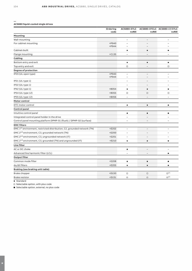
104 A B B I N D U S TR I A L D R I V E S , AC S 8 8 0, S I N G L E D R I V E S , C ATA LO G
R
Ordering code
ACS880-07LCnxR8i
ACS880-07CLCnxR8i
ACS880-17/37LCnxR8i
Mounting
Wall-mounting – – –
For cabinet mounting +P940 +P944
––
––
––
Cabinet-built
Flange mounting +C135 – – –
Cabling
Bottom entry and exit
Top entry and exit –
Degree of protection
IP20 (UL open type) +P940 +P944
––
––
––
IP21 (UL type 1) – – –
IP22 (UL type 1) – – –
IP42 (UL type 1) +B054
IP54 (UL type 12) +B055
IP55 (UL type 12) +B056 – – –
Motor control
DTC motor control
Control panel
Intuitive control panel
Integrated control panel holder in the drive – – –
Control panel mounting platform DPMP-01 (flush) / DPMP-02 (surface) – – –
EMC filters
EMC 1st environment, restricted distribution, C2, grounded network (TN) +E202 – – –
EMC 2nd environment, C3, grounded network (TN) +E200 – – –
EMC 2nd environment, C3, ungrounded network (IT) +E201 – – –
EMC 2nd environment, C3, grounded (TN) and ungrounded (IT) +E210
Line filter
AC or DC choke – –
Advanced line harmonic filter (LCL) – –
Output filter
Common mode filter +E208
du/dt filters +E205
Braking (see braking unit table)
Brake chopper +D150 27)
Brake resistor +D151 27)
Standard Selectable option, with plus code Selectable option, external, no plus code
—ACS880 liquid-cooled single drives

105SU M M A R Y O F FE AT U R E S A N D O P TI O NS
R
Ordering code
ACS880-07LCnxR8i
ACS880-07CLCnxR8i
ACS880-17/37LCnxR8i
Software
Primary control program
Drive application programming based on IEC 61131-3 using Drive Application Builder (available for primary control program)
+N8010
Application control program for winder +N5000 –
Application control program for crane +N5050
Application control program for winch +N5100
Application control program for centrifuge/decanter +N5150
Application control program for PCP pump +N5200
Application control program for Rod pump +N5250 –
Application control program for test bench +N5300 –
Application control program for cooling tower direct drive +N5350 – – –
Application control program for override control +N5450 –
Application control program for spinning and traverse +N5500 – – –
Application control program for chemical industry process control +N5550 – – –
Application control program for ESP pumps +N5600
Application control program for tower cranes +N5650 – – –
Application control program for position control +N5700 24) 24) 24)
Support for asynchronous motor
Support for permanent magnet motor
Support for synchronous reluctance motor (SynRM) +N7502
High speed license. Allows high speedoperation above 598 Hz output frequency.
+N8200 24) 24) 24)
Rectifier bridge
12-pulse +A004 –
24-pulse – –
Line side apparatus
aR line fuses
Main switch – – –
Line contactor +F250 – – –
Air circuit breaker +F255 –
Earthing switch +F259 –
Cabinet options
Cabinet heater (ext. supply) +G300
Output for motor heater (ext. supply) +G313
Customized options +P902
Standard Selectable option, with plus code Selectable option, external, no plus code
—ACS880 liquid-cooled single drives
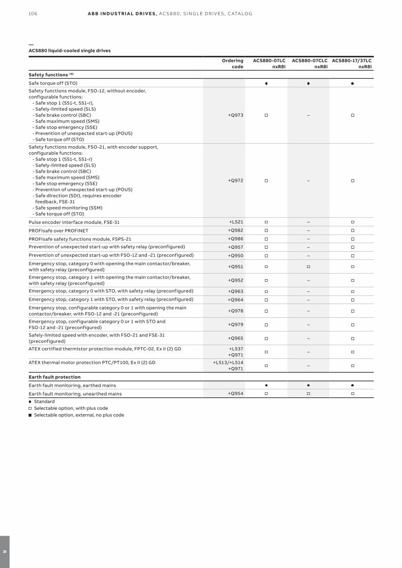
106 A B B I N D U S TR I A L D R I V E S , AC S 8 8 0, S I N G L E D R I V E S , C ATA LO G
R
Ordering code
ACS880-07LCnxR8i
ACS880-07CLCnxR8i
ACS880-17/37LCnxR8i
Safety functions 18)
Safe torque off (STO)
Safety functions module, FSO-12, without encoder, configurable functions:
- Safe stop 1 (SS1-t, SS1-r), - Safely-limited speed (SLS) - Safe brake control (SBC) - Safe maximum speed (SMS) - Safe stop emergency (SSE)- Prevention of unexpected start-up (POUS)- Safe torque off (STO)
+Q973 –
Safety functions module, FSO-21, with encoder support, configurable functions:
- Safe stop 1 (SS1-t, SS1-r) - Safely-limited speed (SLS) - Safe brake control (SBC)- Safe maximum speed (SMS)- Safe stop emergency (SSE)- Prevention of unexpected start-up (POUS)- Safe direction (SDI), requires encoder
feedback, FSE-31- Safe speed monitoring (SSM)- Safe torque off (STO)
+Q972 –
Pulse encoder interface module, FSE-31 +L521 –
PROFIsafe over PROFINET +Q982 –
PROFIsafe safety functions module, FSPS-21 +Q986 –
Prevention of unexpected start-up with safety relay (preconfigured) +Q957 –
Prevention of unexpected start-up with FSO-12 and -21 (preconfigured) +Q950 –
Emergency stop, category 0 with opening the main contactor/breaker, with safety relay (preconfigured)
+Q951
Emergency stop, category 1 with opening the main contactor/breaker, with safety relay (preconfigured)
+Q952 –
Emergency stop, category 0 with STO, with safety relay (preconfigured) +Q963 –
Emergency stop, category 1 with STO, with safety relay (preconfigured) +Q964 –
Emergency stop, configurable category 0 or 1 with opening the main contactor/breaker, with FSO-12 and -21 (preconfigured)
+Q978 –
Emergency stop, configurable category 0 or 1 with STO and FSO-12 and -21 (preconfigured)
+Q979 –
Safely-limited speed with encoder, with FSO-21 and FSE-31 (preconfigured)
+Q965 –
ATEX certified thermistor protection module, FPTC-02, Ex II (2) GD +L537 +Q971
–
ATEX thermal motor protection PTC/PT100, Ex II (2) GD +L513/+L514 +Q971
–
Earth fault protection
Earth fault monitoring, earthed mains
Earth fault monitoring, unearthed mains +Q954
Standard Selectable option, with plus code Selectable option, external, no plus code
—ACS880 liquid-cooled single drives
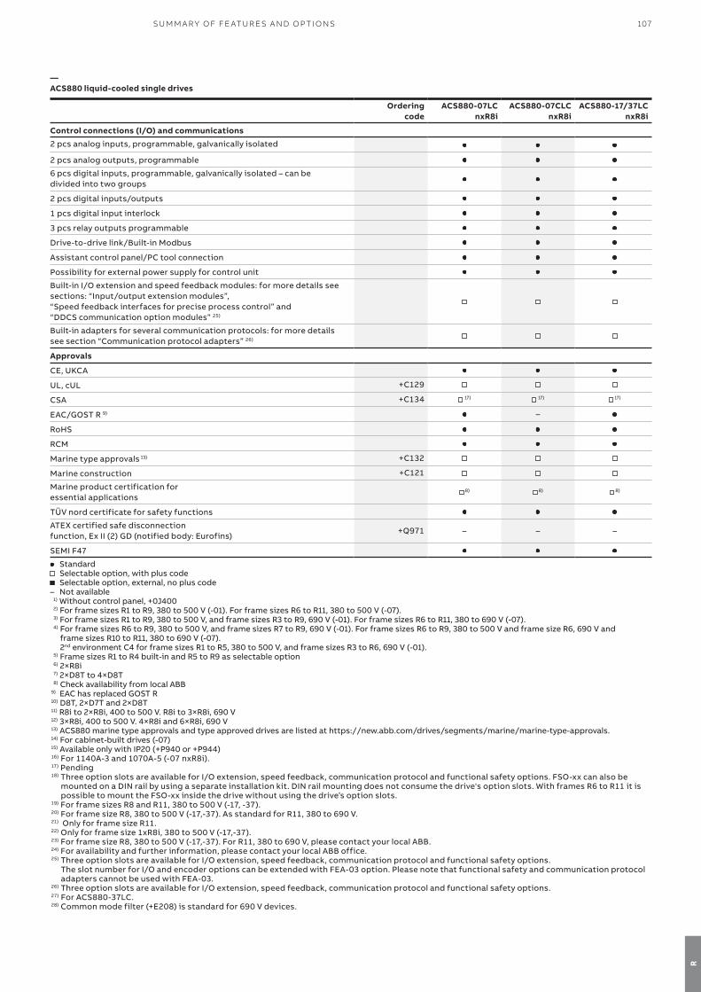
107SU M M A R Y O F FE AT U R E S A N D O P TI O NS
R
Ordering code
ACS880-07LCnxR8i
ACS880-07CLCnxR8i
ACS880-17/37LCnxR8i
Control connections (I/O) and communications
2 pcs analog inputs, programmable, galvanically isolated
2 pcs analog outputs, programmable
6 pcs digital inputs, programmable, galvanically isolated – can be divided into two groups
2 pcs digital inputs/outputs
1 pcs digital input interlock
3 pcs relay outputs programmable
Drive-to-drive link/Built-in Modbus
Assistant control panel/PC tool connection
Possibility for external power supply for control unit
Built-in I/O extension and speed feedback modules: for more details see sections: “Input/output extension modules”,“Speed feedback interfaces for precise process control” and “DDCS communication option modules” 25)
Built-in adapters for several communication protocols: for more details see section “Communication protocol adapters” 26)
Approvals
CE, UKCA
UL, cUL +C129
CSA +C134 17) 17) 17)
EAC/GOST R 9) –
RoHS
RCM
Marine type approvals 13) +C132
Marine construction +C121
Marine product certification for essential applications
8) 8) 8)
TÜV nord certificate for safety functions
ATEX certified safe disconnectionfunction, Ex II (2) GD (notified body: Eurofins)
+Q971 – – –
SEMI F47
Standard Selectable option, with plus code Selectable option, external, no plus code
– Not available1) Without control panel, +0J400 2) For frame sizes R1 to R9, 380 to 500 V (-01). For frame sizes R6 to R11, 380 to 500 V (-07).3) For frame sizes R1 to R9, 380 to 500 V, and frame sizes R3 to R9, 690 V (-01). For frame sizes R6 to R11, 380 to 690 V (-07).4) For frame sizes R6 to R9, 380 to 500 V, and frame sizes R7 to R9, 690 V (-01). For frame sizes R6 to R9, 380 to 500 V and frame size R6, 690 V and
frame sizes R10 to R11, 380 to 690 V (-07). 2nd environment C4 for frame sizes R1 to R5, 380 to 500 V, and frame sizes R3 to R6, 690 V (-01).
5) Frame sizes R1 to R4 built-in and R5 to R9 as selectable option6) 2×R8i 7) 2×D8T to 4×D8T 8) Check availability from local ABB
9) EAC has replaced GOST R10) D8T, 2×D7T and 2×D8T 11) R8i to 2×R8i, 400 to 500 V. R8i to 3×R8i, 690 V12) 3×R8i, 400 to 500 V. 4×R8i and 6×R8i, 690 V13) ACS880 marine type approvals and type approved drives are listed at https://new.abb.com/drives/segments/marine/marine-type-approvals.14) For cabinet-built drives (-07)15) Available only with IP20 (+P940 or +P944)16) For 1140A-3 and 1070A-5 (-07 nxR8i).17) Pending18) Three option slots are available for I/O extension, speed feedback, communication protocol and functional safety options. FSO-xx can also be
mounted on a DIN rail by using a separate installation kit. DIN rail mounting does not consume the drive's option slots. With frames R6 to R11 it is possible to mount the FSO-xx inside the drive without using the driveʼs option slots.
19) For frame sizes R8 and R11, 380 to 500 V (-17, -37).20) For frame size R8, 380 to 500 V (-17,-37). As standard for R11, 380 to 690 V.21) Only for frame size R11.22) Only for frame size 1xR8i, 380 to 500 V (-17,-37).23) For frame size R8, 380 to 500 V (-17,-37). For R11, 380 to 690 V, please contact your local ABB.24) For availability and further information, please contact your local ABB office.25) Three option slots are available for I/O extension, speed feedback, communication protocol and functional safety options.
The slot number for I/O and encoder options can be extended with FEA-03 option. Please note that functional safety and communication protocol adapters cannot be used with FEA-03.
26) Three option slots are available for I/O extension, speed feedback, communication protocol and functional safety options.27) For ACS880-37LC.28) Common mode filter (+E208) is standard for 690 V devices.
—ACS880 liquid-cooled single drives

108 A B B I N D U S TR I A L D R I V E S , AC S 8 8 0, S I N G L E D R I V E S , C ATA LO G
—Notes

109N OTE S
Additional informationWe reserve the right to make technical changes or modify the contents of this document without prior notice. With regard to purchase orders, the agreed particulars shall prevail. ABB does not accept any responsibility whatsoever for potential errors or possible lack of infor-mation in this document.
We reserve all rights in this document and in the subject matter and illustra-tions contained therein. Any reproduc-tion, disclosure to third parties or utilization of its contents – in whole or in parts – is forbidden without prior written consent of ABB.
110 A B B I N D U S TR I A L D R I V E S , AC S 8 8 0, S I N G L E D R I V E S , C ATA LO G

© Copyright 2022 ABB. All rights reserved. Specifications subject to change without notice. 3A
UA
00
00
09
811
1 R
EV
Q E
N 2
4.6
.20
22
—For more information, please contact your local ABB representative or visit
new.abb.com/drives/ACS880new.abb.com/drivesnew.abb.com/drives/drivespartnersnew.abb.com/motors-generators
Video playlist: ACS880 how-to videos
Related Documents