— RELION® PROTECTION AND CONTROL 615 series IEC 60870-5-103 Communication Protocol Manual

Welcome message from author
This document is posted to help you gain knowledge. Please leave a comment to let me know what you think about it! Share it to your friends and learn new things together.
Transcript

—RELION® PROTECTION AND CONTROL
615 seriesIEC 60870-5-103 CommunicationProtocol Manual


Document ID: 1MRS756710Issued: 2018-12-20
Revision: HProduct version: 5.0 FP1
© Copyright 2018 ABB. All rights reserved

Copyright
This document and parts thereof must not be reproduced or copied without writtenpermission from ABB, and the contents thereof must not be imparted to a third party,nor used for any unauthorized purpose.
The software or hardware described in this document is furnished under a license andmay be used, copied, or disclosed only in accordance with the terms of such license.
TrademarksABB and Relion are registered trademarks of the ABB Group. All other brand orproduct names mentioned in this document may be trademarks or registeredtrademarks of their respective holders.
WarrantyPlease inquire about the terms of warranty from your nearest ABB representative.
www.abb.com/relion

Disclaimer
The data, examples and diagrams in this manual are included solely for the concept orproduct description and are not to be deemed as a statement of guaranteed properties.All persons responsible for applying the equipment addressed in this manual mustsatisfy themselves that each intended application is suitable and acceptable, includingthat any applicable safety or other operational requirements are complied with. Inparticular, any risks in applications where a system failure and/or product failurewould create a risk for harm to property or persons (including but not limited topersonal injuries or death) shall be the sole responsibility of the person or entityapplying the equipment, and those so responsible are hereby requested to ensure thatall measures are taken to exclude or mitigate such risks.
This product has been designed to be connected and communicate data andinformation via a network interface which should be connected to a secure network.It is the sole responsibility of the person or entity responsible for networkadministration to ensure a secure connection to the network and to take the necessarymeasures (such as, but not limited to, installation of firewalls, application ofauthentication measures, encryption of data, installation of anti virus programs, etc.)to protect the product and the network, its system and interface included, against anykind of security breaches, unauthorized access, interference, intrusion, leakage and/ortheft of data or information. ABB is not liable for any such damages and/or losses.
This document has been carefully checked by ABB but deviations cannot becompletely ruled out. In case any errors are detected, the reader is kindly requested tonotify the manufacturer. Other than under explicit contractual commitments, in noevent shall ABB be responsible or liable for any loss or damage resulting from the useof this manual or the application of the equipment.

Conformity
This product complies with the directive of the Council of the European Communitieson the approximation of the laws of the Member States relating to electromagneticcompatibility (EMC Directive 2004/108/EC) and concerning electrical equipment foruse within specified voltage limits (Low-voltage directive 2006/95/EC). Thisconformity is the result of tests conducted by ABB in accordance with the productstandard EN 60255-26 for the EMC directive, and with the product standards EN60255-1 and EN 60255-27 for the low voltage directive. The product is designed inaccordance with the international standards of the IEC 60255 series.

Table of contents
Section 1 Introduction.......................................................................3This manual........................................................................................ 3Intended audience.............................................................................. 3Product documentation.......................................................................4
Product documentation set............................................................4Document revision history............................................................. 4Related documentation..................................................................5
Symbols and conventions...................................................................5Symbols.........................................................................................5Document conventions..................................................................5
Section 2 IEC 60870-5-103 overview...............................................7IEC 60870-5-103 standard................................................................. 7Documentation................................................................................... 8
Section 3 Vendor-specific implementation....................................... 9Product series implementation........................................................... 9Communication link............................................................................ 9
Communication link setup........................................................... 10Diagnostic counters.....................................................................11
IEC 60870-5-103 process data.........................................................12IEC 60870-5-103 data objects.....................................................12Indications................................................................................... 12
ASDU 2 type fault number and relative time data.................. 13Configuring of IEC 60870-5-103 indications...........................13Class 1 event overflow........................................................... 14Chronology of Class 1 events................................................ 14Class 1 data message priorities............................................. 15LED objects............................................................................ 15
Analog events..............................................................................16Configuring of analog events..................................................16Value interpretation................................................................ 17
Controls....................................................................................... 17Circuit breaker control model................................................. 17Local, Remote, Station, All and Off states..............................17Control operation rejections................................................... 18
Measurands.................................................................................18Class 2 measurands...............................................................18Other Class 2 measurand frames.......................................... 19Selection of Class 2 frame..................................................... 20
Table of contents
615 series 1Communication Protocol Manual

Scaling of Class 2 measurands .............................................20Unsupported analog values....................................................20Measurand events and registration objects............................20
Energy counters.......................................................................... 21Operation principle................................................................. 22Interpretation of the counter values........................................23
Accessing of non-protocol-mapped data.....................................23Other IEC 60870-5-103 data............................................................ 24
Changing of parameter setting group..........................................24Device identification.....................................................................25
Device function type............................................................... 25Device identification code.......................................................25
Time synchronization...................................................................26Block monitoring..........................................................................26
Disturbance recorder file transfer..................................................... 26Disturbance recorder file directory (ASDU 23)............................ 26Disturbance recorder channel identification................................ 27Disturbance recorder tags identification...................................... 28Disturbance recorder transfer......................................................29
Non-standard features......................................................................29GI optimization.............................................................................30
Troubleshooting................................................................................31
Section 4 IEC 60870-5-103 parameters and diagnostics...............33Parameter list................................................................................... 33Monitored data..................................................................................35
Section 5 Glossary......................................................................... 37
Table of contents
2 615 seriesCommunication Protocol Manual

Section 1 Introduction
1.1 This manual
The communication protocol manual describes a communication protocol supportedby the protection relay. The manual concentrates on vendor-specificimplementations.
1.2 Intended audience
This manual addresses the communication system engineer or system integratorresponsible for pre-engineering and engineering the communication setup in asubstation from a protection relay's perspective.
The system engineer or system integrator must have a basic knowledge ofcommunication in protection and control systems and thorough knowledge of thespecific communication protocol.
1MRS756710 H Section 1Introduction
615 series 3Communication Protocol Manual

1.3 Product documentation
1.3.1 Product documentation set
Pla
nnin
g &
pu
rcha
se
Eng
inee
ring
Inst
alla
tion
Com
mis
sion
ing
Ope
ratio
n
Mai
nten
ance
Dec
omm
issi
onin
g,
dein
stal
latio
n &
dis
posa
l
Quick start guideQuick installation guideBrochureProduct guideOperation manualInstallation manualConnection diagramEngineering manualTechnical manualApplication manualCommunication protocol manualIEC 61850 engineering guidePoint list manualCyber security deployment guideline
GUID-12DC16B2-2DC1-48DF-8734-0C8B7116124C V2 EN
Figure 1: The intended use of documents during the product life cycle
Product series- and product-specific manuals can be downloadedfrom the ABB Web site http://www.abb.com/relion.
1.3.2 Document revision historyDocument revision/date Product series version HistoryA/2009-03-04 2.0 First release
B/2009-07-03 2.0 Content updated
C/2010-06-11 3.0 Content updated to correspond to theproduct series version
D/2012-05-11 4.0 Content updated to correspond to theproduct series version
E/2014-01-24 5.0 Content updated to correspond to theproduct series version
F/2015-10-30 5.0 FP1 Content updated to correspond to theproduct series version
G/2016-05-20 5.0 FP1 Content updated
H/2018-12-20 5.0 FP1 Content updated
Section 1 1MRS756710 HIntroduction
4 615 seriesCommunication Protocol Manual

Download the latest documents from the ABB Web sitehttp://www.abb.com/relion.
1.3.3 Related documentation
Product-specific point list manuals and other product series- and product-specificmanuals can be downloaded from the ABB Web sitehttp://www.abb.com/substationautomation.
1.4 Symbols and conventions
1.4.1 Symbols
The caution icon indicates important information or warning relatedto the concept discussed in the text. It might indicate the presence ofa hazard which could result in corruption of software or damage toequipment or property.
The information icon alerts the reader of important facts andconditions.
The tip icon indicates advice on, for example, how to design yourproject or how to use a certain function.
Although warning hazards are related to personal injury, it is necessary to understandthat under certain operational conditions, operation of damaged equipment may resultin degraded process performance leading to personal injury or death. Therefore,comply fully with all warning and caution notices.
1.4.2 Document conventions
A particular convention may not be used in this manual.
• Abbreviations and acronyms are spelled out in the glossary. The glossary alsocontains definitions of important terms.
• Push button navigation in the LHMI menu structure is presented by using thepush button icons.To navigate between the options, use and .
• Menu paths are presented in bold.Select Main menu/Settings.
• LHMI messages are shown in Courier font.
1MRS756710 H Section 1Introduction
615 series 5Communication Protocol Manual

To save the changes in nonvolatile memory, select Yes and press .• Parameter names are shown in italics.
The function can be enabled and disabled with the Operation setting.• Parameter values are indicated with quotation marks.
The corresponding parameter values are "On" and "Off".• Input/output messages and monitored data names are shown in Courier font.
When the function starts, the START output is set to TRUE.• This document assumes that the parameter setting visibility is "Advanced".
Section 1 1MRS756710 HIntroduction
6 615 seriesCommunication Protocol Manual

Section 2 IEC 60870-5-103 overview
2.1 IEC 60870-5-103 standard
IEC 60870-5-103 is defined as a companion standard for the informative element ofprotection equipment. While the official IEC 60870-5-103 standard dates back to1997, the protocol has its roots in the VDEW6 communication protocol from the late1980’s. A VDEW6 device can be seen as a subset of an IEC 60870-5-103 device butnot the opposite.
IEC 60870-5-103 defines communication for a serial, unbalanced link only.Communication speeds are defined as either 9600 or 19200 baud.
Standard documentationThis manual assumes that the reader has some basic knowledge of the IEC60870-5-103 protocol and the standard IEC 60870 documents relating to the protocol.
Table 1: Standard IEC 60870 documents relating to IEC 60870-5-103
IEC 60870document part
Description
5-1 Transmission frame formats
5-2 Link transmission procedures
5-3 General structure of application data
5-4 Definition and coding of application information elements
5-5 Basic application functions
5-6 Conformance testing guidelines
5-103 Companion standard for the informative interface of protection equipment.
The IEC 60870-5-1…6 parts are also used in communication protocols like IEC60870-5-101 and IEC 60870-5-104.
Interoperability and interchangeabilityAn IEC 60870-5-103 device can be interoperable and interchangeable or onlyinteroperable. Interoperability means that any required application data in the device,which can be coded into an IEC 60870-5-103 data type, can be mapped into the IEC60870-5-103 address space. This data is recognized by any IEC 60870-5-103 master.
Interchangeability means supporting the application data (informative elements)whose semantics are pre-defined by the IEC 60870-5-103 standard. However, only avery limited set of application data informative elements has been defined by thestandard. It should also be noticed that these sets of data are mainly defined for a
1MRS756710 H Section 2IEC 60870-5-103 overview
615 series 7Communication Protocol Manual

single-function protection IED. The 615 series IEDs in turn are multifunctionalprotection and control IEDs whose internal data model is based on the IEC 61850standard.
Interoperability listThe standard requires the IEC 60870-5-103 device to provide an interoperability list,which actually is more an interchangeability list. See the point list manual for acomplete list of all IEC 60870-5-103 data available in a specific IED.
Default data mapping principleWhenever possible, process data is mapped into standard IEC 60870-5-103 functiontypes and information numbers. When this is not possible, the process data is mappedinto private function types and information numbers. General principle of themapping is to keep all process data belonging to the same function design inside thesame IEC 60870-5-103 function type definition. However, if this default mappingprinciple causes interoperability problems with older installations, every availableIEC 60870-5-103 process data point can be freely remapped with PCM600. All themapped data is not in use by default.
2.2 Documentation
Address information concerning IEC 60870-5-103 process data stated in thisdocument is similar in all 615 series IEDs. The rest of the IEC 60870-5-103application data are IED variant dependent.
A newer SW version of the same IED configuration may containadditional IEC 60870-5-103 points.
The IEC 60870-5-103 points list documentation of a certain IED configuration andSW version is available in addition to this document. It is essential to know the devicetype, configuration name and SW version to locate the correct IEC 60870-5-103points listings.
Table 2: Example of IED information needed to locate the correct IEC 60870-5-103 points list
LHMI or WHMI path IED informationInformation/Product identifiers/Type REF615
Information/Product identifiers/Configuration name FE01
Information/Product identifiers/SW version 1.0
Section 2 1MRS756710 HIEC 60870-5-103 overview
8 615 seriesCommunication Protocol Manual

Section 3 Vendor-specific implementation
3.1 Product series implementation
IEC 60870-5-103 is specified for single function protective equipment with a limitedset of process data. Some extensions are necessary for supporting the IEDs.
• Multiple protection functionality• Objects with four valid positions such as circuit breakers or disconnectors• Circuit breaker and disconnector control operations• Class 1 event overflow handling
Since these features are not a part of the IEC 60870-5-103 standard, it is not likely thatdifferent vendors have implemented them in the same manner. However, it isguaranteed that the IEDs in this product series are equally implemented concerningthese features. In addition of having product series-specific default settings for privatefunction type and information number application data definitions, the user canreprogram these settings if required. The user can also affect the way in which Class1 event overflows should be treated and reported.
ASDU type 2 data is generally supported. This means the generation of a fault numberand a relative time stamp for protection related Class 1 events. Despite the defaultASDU type settings it is possible for the user to configure either ASDU type 1 or 2separately for each private Class 1 data.
Different Class 2 measurand value sets are selectable. All the standardized ASDU 3(Meas I) and ASDU 9 (Meas II) sets can be selected. Additionally some IED-dependent private ASDU 9 frames are also provided. It is also possible for the user tofreely define an own (private) Class 2 measurand set.
IEC 60870-5-103 disturbance files are supported. The IEC 60870-5-103communication stack adapter contains a conversion functionality between the IED'snative disturbance recorder files and the IEC 60870-5-103 specific disturbancerecorder data and settings definitions.
3.2 Communication link
The IEC 60870-5-103 protocol can only operate on a serial communication link. Thestandard defines serial data characteristics.
1MRS756710 H Section 3Vendor-specific implementation
615 series 9Communication Protocol Manual

Table 3: Serial data characteristics
Parameter ValueCom speed 9600 or 19200 bauds
Data bits 8
Parity Even
Start bits 1
Stop bits 1
Depending on the IED model and variant, the serial communication cards can host oneor several serial channels. The IEC 60870-5-103 protocol can operate in up to twoinstances and therefore supporting two IEC 60870-5-103 masters in parallel. The twoinstances will share the same point configuration, but each instance has its ownindependent Class 1 event buffer. Instances can also have different Class 2 measurandframes. Separate link setting parameters exist for both instances. Setting parametershave the suffixes 1 or 2 depending on the instance.
A function block represents the IEC 60870-5-103 protocol on the IED’s applicationconfiguration level. The block is named I3CLPRT1 or I3CLPRT2, depending onwhich of the two protocol instances is in use.
I3CLPRT
EC_FRZ STATUS
GUID-B230DC02-9257-4A70-A16D-2FC4A9D35CD6 V1 EN
Figure 2: Function block
By default, Instance 1 is active in the IED, but needs to be set “On” by the Operationparameter. For additional clients, an instance has to be activated by dragging afunction block to the configuration in the Application Configuration tool of thePCM600.
3.2.1 Communication link setup
Serial communication link setup in the IED is divided between serial driver setup andprotocol link setup. Serial drivers are related to the physical serial ports of the IED. Ifthe IED has two physical ports, they are named COM1 and COM2. Setting parametersfor COMn (n = 1 or 2) ports are found in Configuration/Communication/COMn.The COMn setting parameters are protocol-independent and related to the physicallink. The communication speed is set in the COMn parameters.
For the COM port parameter settings and hardware setup, see thetechnical manual.
Section 3 1MRS756710 HVendor-specific implementation
10 615 seriesCommunication Protocol Manual

The COM port connection type, optical ST or EIA-485 connection,star or loop topology, idle state (light on or light off) and the bias andbus termination are selected with the COM port jumpers.
Depending on the communication card, the optical connection may beavailable only for one COM port (1 or 2). See the technical manual formore information.
Once the COMn port is configured, the next step is to attach the IEC 60870-5-103protocol to the port. This is done by the setting parameters of the communicationprotocol in question. The IEC 60870-5-103 protocol setting parameters are located inConfiguration/Communication/IEC 60870-5-103/I3C0n.
For example, serial port has to be set to “COM2” and Address to “25” to attach IEC60870-5-103 to the COM2 port and assign the link unit address to 25.
• Serial port = “COM2”• Address = “25”
3.2.2 Diagnostic counters
The IEC 60870-5-103 protocol diagnostic counters can be viewed via menu pathMonitoring/Communication/IEC 60870-5-103/I3C0n. Counters related to the IEC60870-5-103 link instances 1 and 2 have the suffixes (n) 1 and 2. The diagnosticcounters show complete IEC 60870-5-103 link frames and link errors. The serialdrivers (COMn) have their own diagnostic counters for lower-level serialcommunication character, error and link messages. The COMn counters count all themessages on the serial line. COMn Link status is “Up” when IEC 103 protocol isdefined to the port, the cable is correctly connected and there is an IEC 103 masterpolling on the line. It is possible to reset the diagnostic counters by setting the Resetcounters value to “True”. The IEC 60870-5-103 instance Status is “True” whenCOMn Link status is “Up” and there is an IEC 103 master polling on the line. When theStatus of the IEC 60870-5-103 instance has never been “True”, the diagnosticcounters belonging to the instance contain value “-1”. Counter value “0” in turn meansthat the instance is in use, but no messages have been detected.
The diagnostic status indication automatically turns from "True" to "False" whenthere has not been any incoming IEC 60870-5-103 messages directed to the IEDwithin 15 seconds. The STATUS indication output is also visible in the I3CLPRTfunction blocks through the Application Configuration tool (ACT) in PCM600. Thisoutput can be used, for example, to lit a dedicated "Communication Error" LED on thefront panel.
1MRS756710 H Section 3Vendor-specific implementation
615 series 11Communication Protocol Manual

Table 4: Protocol diagnostic counters (I3C01 and I3C02)
Attribute Values (range) Default DescriptionStatus False = Communication inactive
True = Communication activeFalse Status (read)
Reset counters False/True False True (reset)
Received frames -1...2147483646 Received frames
Checksum errors -1...2147483646 Checksum errors
Transmitted frames -1...2147483646 Transmitted frames
3.3 IEC 60870-5-103 process data
3.3.1 IEC 60870-5-103 data objects
The IEC 60870-5-103 protocol in the IEDs is built on top of the internal IEC 61850data model. Thus, the IEC 60870-5-103 application data objects and Class 1 events arederived from IEC 61850 data objects and data set reporting. The IEDs have apredefined IEC 61850 data set configuration. In other words, it is predefined whichinternal data object changes the IEDs detect.
The available IEC 60870-5-103 Class 1 data objects in the IEDs are selected from theobjects predefined in the IEC 61850 data sets. IEC 61850 data set reporting and IEC60870-5-103 Class 1 event reporting are basically identical.
For a list of the available data objects, see the point list manual.
3.3.2 Indications
The IEC 60870-5-103 standard defines indications to be of ON/OFF type. The valuecoding for indications is always DPI, where only values 1 and 2 (binary 01 and 10) areused. Value 1 means OFF and value 2 means ON. Indications are assigned to IEC60870-5-103 Class 1 data transactions.
Indications relate to general purpose signals or protection signals (start and trip). Thestandard defines two ASDU object types for indications: ASDU 1 and ASDU 2.ASDU 1 type is intended for general purpose objects and ASDU 2 type for protectionobjects. These ASDU types are shown as TypeID 1 and TypeID 2 in theCommunication Management tool of PCM600.
The IEC 60870-5-103 standard was originally defined for protective equipment only.Therefore the standard does not include circuit breaker control and object definitions.For circuit breaker and disconnector position information the IEC 60870-5-103 DPIvalue is extended to include the values 0 and 3 (binary 00 and 11) also. These valuesrepresent the four-pole object’s intermediate and faulty positions.
Section 3 1MRS756710 HVendor-specific implementation
12 615 seriesCommunication Protocol Manual

3.3.2.1 ASDU 2 type fault number and relative time data
In addition to the absolute event time stamp, the ASDU 2 type requires that themessage also contains a fault number and relative time data. However, these are notavailable in the IEC 61850 data model. Therefore, the IEC 60870-5-103 stackautomatically creates a fault number, which is incremented each time the IED'sinternal IEC 61850 data attribute LD0.LEDPTRC1.Str.general (Start LED) isactivated. Relative time is calculated from the time stamp of this same IEC 61850 dataattribute. Relative time is represented as a 16 bit millisecond value which saturates toits maximum value 65535 ms if necessary.
3.3.2.2 Configuring of IEC 60870-5-103 indications
With PCM600 the user can reconfigure the default IEC 60870-5-103 indicationdefinitions.
• Add or remove existing indications• Change function type/information number definition of indication• Restore default function type/information number definition of indications• Change GI assignment of indications• Change ASDU type used by the indications• Change the data coding value (DPI) representation (four-pole objects only)• Suppress falling edge Class 1 events (non-standard feature)
Function type 0 has a special meaning for indications. An indication with FunType= ”0” is changed into parameter DevFunType value for event reporting, generalinterrogation, and recorded data.
Changing the DPI value representation means that the DPI value only shows thestandard defined ON and OFF values instead of four-pole values ON, OFF,INTERMEDIATE and FAULTY.
Table 5: Conversion rule for the DPI value representation
True object position IEC 60870-5-103 valueCLOSED ON
OPEN OFF
INTERMEDIATE ON
FAULTY ON
Suppressing the falling edge, that is the OFF Class 1 events, is useful in some cases.For example, the Operate-OFF signals could often be omitted. This decreases theamount of Class 1 events and thus saves the bandwidth.
Suppressing the OFF event is an non-standard feature. The standardrequires that every position change of a Class 1 object is reported.
1MRS756710 H Section 3Vendor-specific implementation
615 series 13Communication Protocol Manual

The difference between a readable/writable object and a write-onlyobject is not visible in the Communication Management tool ofPCM600. An object is of write-only type if it is located on an IEC61850 Oper.ctlVal data attribute. In this case, the GI enabling andother possible event configuration settings are meaningless.
3.3.2.3 Class 1 event overflow
The size of the Class 1 event buffer in the IED is 500 events. The IEC 60870-5-103standard does not define any method of indicating Class 1 event buffer overflows.Instead, the standard suggests that the master performs a general interrogationintegrity scan every 15 minutes (or more), to detect indications that have not beenupdated spontaneously.
The IED contains a special overflow Class 1 ASDU 1 indication. The default settingof this overflow indication is FUN = 10, INF = 255. The FUN/INF definition can bechanged if required. This object creates an ON event when the overflow occurs. It isalso possible to take the overflow operation completely out of use and operate withoutany overflow indication as the IEC 60870-5-103 standard defines. The IEC60870-5-103 instances can also be configured differently.
There are four setting parameters related to the IEC 60870-5-103 Class 1 overflowoperation in the IED. The setting parameters are located in Configuration/Communication/IEC 60870-5-103/I3C0n (parameter suffix n = 1 or 2, dependingon the instance).
• Class1OvInd n: takes the overflow object into use. Settings: No indication, Bothedges, Rising edge.
• Class1OvFType n: defines the Function Type (FUN) for the overflow indication.• Class1OvInfNo n: defines the Information Number (INF) for the overflow
indication.• Class1OvBackOff n: defines how many events have to be emptied from the Class
1 event buffer until new ones are collected. Default setting is “500” (meaning thewhole event buffer must be emptied).
The overflow operation preserves the oldest events in the buffer. The overflow Class1 event is given the time stamp of the indication that first created the overflowsituation. In other words, the indication event is lost and replaced with the Class 1overflow event.
3.3.2.4 Chronology of Class 1 events
In some special cases it is possible that Class 1 events can be transmitted in a wrongchronological order. However, this never occurs for the same object and the timestamps for all Class 1 events are always correct. Reason for the disorder can be thefiltering time of a physical digital input, or suppressing of the intermediate state offour-pole objects. Event detection time and reporting time are different in these cases.
Section 3 1MRS756710 HVendor-specific implementation
14 615 seriesCommunication Protocol Manual

3.3.2.5 Class 1 data message priorities
1. User command responses (highest priority)2. Class 1 change events3. Disturbance file transfer messages4. General interrogation data responses (lowest priority)
Disturbance file transfer increases the overall response time for Class 1 change eventson the IEC 60870-5-103 interface. The standard does not suggest any particularpriority division between these two message types. It is therefore possible to configurethe priority division between the Class 1 change events and disturbance file transfermessages. There are three possible priority levels:
• Ev High: Class 1 change events has higher priority.• Ev/DR Equal: Priority is equal between the two message types.• DR High: Disturbance file transfer has higher priority.
The setting parameter for the priority level is located via Configuration/Communication/IEC 60870-5-103/I3C0n/Class1Priority. Default level is EvHigh.
3.3.2.6 LED objects
The user-definable LHMI LED object is also visible as IEC 60870-5-103 Class 1 data.In older IED versions, the LED object had only two positions: Off and Alarm (red).The corresponding IEC 60870-5-103 Class1 LED data area shows DPI values off,“01” for Off and values on, “10” for Alarm.
In the new LED versions, the IED LED objects can be configured to use severaloptions and colors. By default, the LED states are defined as Off, OK (green) andAlarm (red). However, the color definition for the OK and Alarm states can beconfigured.
Two IEC 60870-5-103 LED protocol data area alternatives are available depending onhow the LEDs are used.
Example 1
If the LEDs are configured to show two positions, for example Off-OK or Off-Alarm,the LED object positions are visible in the digital input LED area 1 with DPI valuesoff “01” for Off and on “10” for OK or Alarm. This coding is the same as in the olderIED versions.
Example 2
If LEDs are configured to show all three positions or the two positions OK-Alarm,LED area 2 can be used. LED area 2 data are by default configured to show all thethree possible LED state values in the extended DPI data octet. This resembles the
1MRS756710 H Section 3Vendor-specific implementation
615 series 15Communication Protocol Manual

coding of double-pole objects. The possible values are “00” for None, “01” for OKand “11” for Alarm.
In case of a two-position “OK-Alarm” LED, the LED area 2 data can be configuredto show normal Off/On DPI-data using the double-point extended value to single-point value conversion. This means that the actual DPI LED values are converted as00-to-10, 01-to-01, (10-to-10), 11-to-10. Thus, the LED state OK (“01”) is shown asvalue “01” (Off) and state Alarm (“11”) as value “10” (On).
LED Pos LED area 1 DPI data LED area 2 DPI data Three statesdetermination
Off OFF - Area1 = Area2 = OFF
OK ON OFF Area1 <> Area2
Alarm ON ON Area1 = Area2 = ON
The two IEC 60870-5-103 LED areas are updated in parallel. LEDs can be configuredindividually. The most suitable IEC 60870-5-103 LED data object for each case canbe chosen.
3.3.3 Analog events
Some selected analog values in the relay are available as so called ASDU 4 or TypeID4 analog Class 1 events. Depending on the supported applications, the values mayinclude the registered maximum current and voltage values during a fault and faultlocator registrations. For example, also tap changer position values can be obtainedthrough TypeID 4.
There is no internal prioritization between TypeID 4 and indicationevents in the IED. Enabling events, for example for fault recordfunction, can cause considerable delay in indication event reporting.It should be carefully considered which TypeID 4 data is included inevent reporting by setting “TypeId4 in use” in the CommunicationManagement tool.
Fault record data can be configured to be generated only at operationsituations. At operation, the circuit breaker opens, and after that, nomore protection or indication events are generated by the IED. In suchcase, the trailing fault record data does not overload the event buffer.
3.3.3.1 Configuring of analog events
The selection of available TypeID 4 values can be seen in the measurand list of theCommunication Management tool in PCM600 with other analog values of the relay.The object state column shows if a measurand is a TypeID 4 object, either in use or not.
Section 3 1MRS756710 HVendor-specific implementation
16 615 seriesCommunication Protocol Manual

By default, most of these objects are not in use. The predefined private function typesand information numbers for these objects can be edited freely.
3.3.3.2 Value interpretation
According to the IEC 60870-5-103 standard, the TypeID 4 value coding format is 32-bit floating point. Since measurands in the relay are natively also mostly of this format,no rescaling of the analog values is needed. In case the native value is of integerformat, then the relay automatically converts this into floating point for TypeID 4. Thescaling factor, seen in the measurands table, does not affect TypeID 4 objects.
3.3.4 Controls
The IEC 60870-5-103 standard defines remote control of indications or control ofobjects without corresponding indication. Example of a controllable indication couldbe circuit breaker ON/OFF whose position can be monitored as a normal ASDU 1indication, and which also can be controlled ON or OFF by the IEC 60870-5-103client. Example of a control object without corresponding indication could be anacknowledge object, for example LED Reset.
According to the standard the remote control operations are performed using theASDU 20 object type. Controllable indications usually can be controlled into twopositions, ON or OFF. Acknowledge points can only be controlled ON. If the IED isin local mode, the remote CB controls are rejected.
3.3.4.1 Circuit breaker control model
Circuit breaker can only be controlled with DIRECT ON/OFF commands. This is dueto the limitations in the IEC 60870-5-103 standard. In case the IED’s internal (IEC61850) circuit breaker control model is set to Select-Before-Operate, the IEC60870-5-103 stack will internally emulate both SELECT and OPERATE commandstoward the circuit breaker. To the IEC 60870-5-103 client the control operationalways appears to be DIRECT.
3.3.4.2 Local, Remote, Station, All and Off states
The relay can be set to five different states: Local, Remote, Station, All or Off. CBcontrols from an IEC 60870-5-103 client are possible when the relay is in the Remote,Station or All state. When the relay is in the Local or Off state, the circuit breakercannot be controlled via IEC 60870-5-103. The IEC 60870-5-103 mapping includestwo ASDU1 ON or OFF points dealing with these states.
First, the classic Local or Remote ON or OFF indication, CTRL.LLN0. Loc, is theeasiest signal to use on the client side. The indication shows "ON" when the relay isin the Local or Off state, and "OFF" when the relay is in the Remote, Station or Allstate. Basically, this object tells if control is possible from the IEC 60870-5-103 clientat a particular moment. This object is sufficient for most users.
1MRS756710 H Section 3Vendor-specific implementation
615 series 17Communication Protocol Manual

The relay cannot distinguish if the IEC 60870-5-103 client is of the Station or Remote(NCC) type. However, it is possible to locally reject the control operations on the IEC60870-5-103 client side based on this indication and information about the client type(NCC or Station).
3.3.4.3 Control operation rejections
The IEC 60870-5-103 standard does not take into account that the IED could haveseveral remote client connections. It should be noticed that a remote control operationcould also be rejected if another remote client is performing a control operation at thesame time. The IED handles the remote command rejection in three different ways.
• Remote command to an existing object, while the IED is in Local mode or the IEDis in Remote mode, but control operation is blocked for some reason (Blockingreasons include simultaneous control being performed by another remote client):• The command is accepted on link level (Link ACK)• The command is rejected on application level (Negative response,
COT=21)• Remote command while the IED is still performing the previous command of the
same client:• The command is rejected on link level (Link NAK, DFC=1)
• Remote command performed on a non-existing object:• The command is rejected on link level (Link NAK, DFC=0)
In the last two cases the DFC flag is used to distinguish the faults.
3.3.5 Measurands
Measurand object transmission is defined by the IEC 60870-5-103 standard. Thestandard does not define any method for transporting integer values like counters orenumeral objects.
Measurands are transmitted as a set of Class 2 data, referred to as a Class 2 measurandsframe. According to the standard the coding of IEC 60870-5-103 measurand objectsmust be 13 bit signed values in the range of -1…+1.
When an IEC 60870-5-103 measurand, for example phase current, is scaled as 2.4, itmeans that the measurand value 1 corresponds to 2.4 × In, measurand value 0.5corresponds to 1.2 × In, and so on. If the measurand value in this case exceeds 2.4 ×In, the IEC 60870-5-103 object value saturates at its maximum value and an overflowflag is set in the IEC 60870-5-103 object transmission.
3.3.5.1 Class 2 measurands
The interchangeable part of the IEC 60870-5-103 standard defines that only five Class2 measurands frames exist. Measurands transmitted in these five Class 2 frames
Section 3 1MRS756710 HVendor-specific implementation
18 615 seriesCommunication Protocol Manual
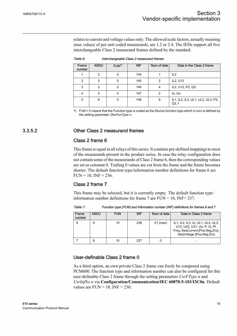
relates to current and voltage values only. The allowed scale factors, actually meaning|max values| of per unit coded measurands, are 1.2 or 2.4. The IEDs support all fiveinterchangeable Class 2 measurand frames defined by the standard.
Table 6: Interchangeable Class 2 measurand frames
Framenumber
ASDU FUN1) INF Num of data Data in the Class 2 frame
1 3 0 144 1 IL2
2 3 0 145 2 IL2, U12
3 3 0 146 4 IL2, U12, P3, Q3
4 3 0 147 2 Io, Uo
5 9 0 148 9 IL1, IL2, IL3, UL1, UL2, UL3, P3,Q3, f
1) FUN = 0 means that the Function type is coded as the Device function type which in turn is defined bythe setting parameter DevFunType n.
3.3.5.2 Other Class 2 measurand frames
Class 2 frame 6This frame is equal in all relays of this series. It contains pre-defined mappings to mostof the measurands present in the product series. In case the relay configuration doesnot contain some of the measurands of Class 2 frame 6, then the corresponding valuesare set as constant 0. Trailing 0 values are cut from the frame and the frame becomesshorter. The default function type/information number definitions for frame 6 areFUN = 10, INF = 236.
Class 2 frame 7This frame may be selected, but it is currently empty. The default function type/information number definitions for frame 7 are FUN = 10, INF= 237.
Table 7: Function type (FUN) and Information number (INF) definitions for frames 6 and 7
Framenumber
ASDU FUN INF Num of data Data in Class 2 frame
6 9 10 236 21 (max) IL1, IL2, IL3, Io, UL1, UL2, UL3,U12, U23, U31, Uo, P, Q, Pf,
Freq, SeqCurrent [Pos,Neg,Zro],SeqVoltage [Pos,Neg,Zro]
7 9 10 237 0 -
User-definable Class 2 frame 0As a third option, an own private Class 2 frame can freely be composed usingPCM600. The function type and information number can also be configured for thisuser-definable Class 2 frame through the setting parameters UsrFType n andUsrInfNo n via Configuration/Communication/IEC 60870-5-103/I3C0n. Defaultvalues are FUN = 10, INF = 230.
1MRS756710 H Section 3Vendor-specific implementation
615 series 19Communication Protocol Manual

See the list of available measurands from the product-specific point list manuals.
3.3.5.3 Selection of Class 2 frame
The Class 2 frame is selected with parameter Frame1InUse n. The user can selectbetween the user-defined frame 0, standard frames 1 to 5, or IED-dependent frames 6and 7. Selection of frames 0 to 7 is possible even if the IED does not produce all thevalues required by the mentioned Class 2 frames. Values that are not available in theIED is set to 0 in the selected Class 2 data frame.
Using of several Class 2 frames simultaneouslyUsing several Class 2 frames simultaneously is not a standard feature. However, it ispossible to define that the IED sends more than one Class 2 frame to the master.Actually up to four Class 2 frames can be defined. The additional Class 2 frameselections is defined in setting parameters Frame2InUse n, Frame3InUse andFrame4InUse. For example, if Frame1InUse is set to ""Private frame 6"" andFrame2InUse is set to "" User frame "", the IED gives out Class 2 "Private frame 6"and Class 2 "User frame" responses to every second Class 2 poll made by the master.
3.3.5.4 Scaling of Class 2 measurands
All Class 2 measurands can be rescaled separately using PCM600. The scale valuedefines the highest value expressed by the IEC 60870-5-103 measurand. Values 1.2and 2.4 are standard values but the IED can actually accept any value. For example,scale 4.0 for IL1 enlarges the measurand range to -4.0*In…+4.0*In. The IEC60870-5-103 measurand value is always signed, regardless if the original value is apositive only value.
3.3.5.5 Unsupported analog values
The IEC 60870-5-103 protocol does not support the transmission of counters orintegrated totals meaning cumulative values such as energy values. The IECTechnical Committee 57 has defined the companion standard IEC 60870-5-102 forthis purpose.
3.3.5.6 Measurand events and registration objects
The relay contains some regular measurands that can be received as ASDU 4 orTypeID 4 change events through the Class 1 buffer. All these objects are disabled bydefault. These objects can be located in the point list and enabled through PCM600.
Depending on the relay configuration, the internal fault record can register variousstart current and voltage and maximum current and voltage values during a faultsituation. The fault reactance and distance to fault can also be registered, providingthat the relay variant supports the fault locator function. The fault record data isavailable as ASDU 4 Class 1 objects. All these objects are disabled by default. Theseobjects can be located in the point list and enabled through PCM600.
Section 3 1MRS756710 HVendor-specific implementation
20 615 seriesCommunication Protocol Manual

Fault recordsThe fault record needs to be separately configured for the desired registration actions.For example, registrations can be defined to be made only at operate (trip) situation,or also at any start on/off situation. The fault record function component contains allregistration object values that could have potentially been used by the relay type inquestion. It depends on the relay variant type and the relay configuration if a certainregistration is made. Objects that are not registered remain constantly at value 0.
The fault record registers several values at the same time. All values belonging to thesame fault get the same ASDU 4 event time stamp. This makes it easy to collectregistrations belonging to the same fault situation.
ASDU 4 events can easily fill up the Class 1 event buffer. The fault record can forexample be configured to register only after an operate (trip) event. In such case, theregistration value events are generated and transmitted following the last “Breakeropen” event, when the relay is idle.
3.3.6 Energy counters
Counters are not defined by the IEC 60870-5-103 standard in general. A private dataunit ASDU 205 is used to define counters. All IEC 60870-5-103 masters does notsupport this non-standard ASDU type.
Table 8: ASDU 205 Class1 event message outlook
Octets Description205 Type ID
0×81 VSQ (= one data)
1 COT (= spontaneous)
Addr Unit address
FUN Function type
INF Information number
LSB Counter value
:
:
MSB
[ms] Time stamp
[min]
[hour]
1MRS756710 H Section 3Vendor-specific implementation
615 series 21Communication Protocol Manual

Table 9: Counter value outlook in detail
Octet Description1 Bits 0...7 = Counter bits 0…7
2 Bits 0…7 = Counter bits 8…15
3 Bits 0…7 = Counter bits 16..23
4 Bits 0…3 = Counter bits 24...27, Bit 4= sign, Bits5...7 = Not used
In practice only the energy values from the internal PEMMTR function are pre-mapped into ASDU 205 values.
Table 10: ASDU 205 pre-mapped values
IEC 61850 object Description FUN INFLD0.PEMMTR1.SupWh.actVal Reversed active energy 133 51
LD0.PEMMTR1.SupVArh.actVal Reversed reactive energy 133 52
LD0.PEMMTR1.DmdWh.actVal Forward active energy 133 53
LD0.PEMMTR1.DmdVArh.actVal Forward reactive energy 133 54
3.3.6.1 Operation principle
The energy counter values are frozen and propagated as ASDU 205 Class1 events withtimestamp-based on a send criteria, that can be freely defined.
Freezing and sendingThe EC_FRZ binary inputs can be seen in the I3CLPRT function blocks through theApplication Configuration tool in PCM600. When a function block detects a risingedge "1" on the EC_FRZ input, it freezes and latches the defined counter valuesamong the present IED real time. Thereafter ASDU205 counter events are created intoClass1 buffer.
Some alternatives for EC_FRZ activation
• A common alternative for the operation is that counters should be frozen andtransmitted cyclically, once a minute. This can be achieved in ApplicationConfiguration tool by defining a 1 minute timer that creates a pulse to theEC_FRZ input. If required it is possible to define other values for the timer, forexample, 10 minutes, 15 minutes, 60 minutes and so on.
• If there are several IEC 60870-5-103 units in the network that should transmitASDU 205 values, freezing can be done at the same moment. The timer signal inone of the units can be connected to a physical binary output signal and wired tophysical binary inputs into the other units. Thereafter, the freezing pulse can besynchronized in all the units.
• Freezing can also be triggered from the IEC 60870-5-103 master unit. The IEDcontains generic control objects like SPCGAPC that can be written from themaster. A generic control object is defined as pulsed type and connected to theEC_FRZ input with Application Configuration tool. If the generic control object
Section 3 1MRS756710 HVendor-specific implementation
22 615 seriesCommunication Protocol Manual

in parallel can be connected to a binary output and wired to other units, abroadcast freeze can be achieved.
3.3.6.2 Interpretation of the counter values
The ASDU 205 counters are derived from the corresponding IEC 61850 counterobjects. Due to range differences, the scaling of the IEC 61850 counter objects are notsimilar to the expected ASDU 205 scaling. With the default settings the difference isapproximately:
ASDU 205 value = 0.2684 × IEC 61850 counter value
Information about how interpret the IEC 61850 counter values in turn are foundelsewhere in the IED documentation.
The scale factor is the quotient between the maximum range values of the differentcounter types.
ASDU 205 counter range is 0…268435455 (0…0×0FFFFFF)
IEC 61850 counter range is 0…999999999 (0…0×3B9AC9FF)
For calculation purposes, the IEC 60870-5-103 protocol needs to know the sourcecounter roll-over value. The roll-over values can be defined through theCommunication Management tool Scale value. Default setting is 1000000000(999999999+1).
3.3.7 Accessing of non-protocol-mapped data
The protection relay application includes a number of general-purpose I/O data. Bydefault, these data are mapped to this protocol. See the point list manual for the exactmappings.
The general-purpose objects can be connected to any internal object in the protectionrelay configuration application using the Application Configuration or Signal Matrixtool. This gives additional opportunities for the protocols.
Example 1Due to security reasons, protocols do not contain mappings for the direct control ofphysical outputs. This way, the client cannot accidentally write a change to a physicaloutput.
It is possible to connect general-purpose outputs to physical outputs using theApplication Configuration tool. The general-purpose output can also be controlledfrom the protocol.
1MRS756710 H Section 3Vendor-specific implementation
615 series 23Communication Protocol Manual

Example 2The legacy protocol default mappings are a selection of the most important signalsproduced by the IEC 61850-based protection relay applications. The manufacturer’sselection of important signals may not always serve every customer.
Any non-protocol-mapped internal signal can be freely connected to a general-purpose input object via the Application Configuration tool. This object can then beaccessed by the legacy protocol as regular protocol application data.
Example 3The basic IEC 61850 application model of the protection relay produces a greatamount of information. In some cases, this is more than what is feasible to transportthrough a legacy protocol. Via the PCM600/Communication Management tools,unnecessary data objects can be excluded from the legacy protocol.
However, in some cases a better solution is to OR together several internal signals intoone general signal. This OR output can be connected to a general-purpose input andaccessed by the legacy protocol as regular protocol application data.
General-purpose input object and OR function block may causedelays to time stamps.
3.4 Other IEC 60870-5-103 data
3.4.1 Changing of parameter setting group
The relay supports remote changing of the used parameter setting group. The sixpossible setting groups in the relay are coded as objects Characteristic 1…Characteristic 6 using standard information numbers 23…28.
On the relay's native IEC 61850 model level the parameter setting group change objectis also a setting parameter in itself, not a process object as is assumed in the IEC60870-5-103 standard. In a normal case, any parameter setting change in the relayrequires that the client first reserves the parameter setting rights, then changes thesetting and finally stores the change. An exception to this is the Parameter settinggroup change parameter. Writing remotely to this parameter automatically includesreservation and storing. Consequently, the setting group writing fails if simultaneousparameter settings are edited via the HMI, or remotely from another master.
Section 3 1MRS756710 HVendor-specific implementation
24 615 seriesCommunication Protocol Manual

3.4.2 Device identification
3.4.2.1 Device function type
The IEC 60870-5-103 standard requires that an IED is identified as a certain Devicetype. The standard has only the following single functional device types:
• 128 distance protection• 160 overcurrent protection device• 176 transformer differential protection• 192 line differential protection
Since the IEDs are multifunctional, the Device type is set to the private function typevalue 9 as default. However, if this definition would cause incompatibility with someclient systems, the definition can be changed through the DevFunType n parameter.
The value in DevFunType n is automatically assigned to all IEC 60870-5-103 datapoints that have their function type defined as 0. The user has to assure that no similarIEC 60870-5-103 point definitions already exist with the same function type andinformation number.
3.4.2.2 Device identification code
The device identification information for the IED consists of three parts.
• Compatibility level (COL) = 2• Eight character ASCII ID string• Internal code = 4 octets
The ASCII string consists of eight characters, for example, 615FE02<space>.
6 2 0 F E 2 0 16 1 5 T E 0 8_
Series (615, 610, 620..)
Device type (REF, RET, REM..)
Region (E=IEC, A=ANSI)
Variant (up to 3 digit number, padding space (_) characters 20Hadded to the end if needed)GUID-0B5D1BA1-7F2F-4BF3-82C6-75842001B2A4 V1 EN
Figure 3: Examples of device identification codes
1MRS756710 H Section 3Vendor-specific implementation
615 series 25Communication Protocol Manual

3.4.3 Time synchronization
Time synchronization over IEC 60870-5-103 is supported. This requires that theIED’s global Time Sychronization Source parameter (in Configuration/Time/Synchronization/Synch source) is set to "IEC 60870-5-103" mode. If some othertime synchronization source is configured for the IED, the IEC 60870-5-103 timesynchronization messages are rejected.
3.4.4 Block monitoring
The Block monitoring setting parameter prevents the relay from sending Class 1events. Two blocking modes exist: the relay can keep or discard the occurring Class1 events during the blocking period. In any case, every Class 1 data object updates itsmomentary value with the latest change event. A general interrogation following theblocking period always reveals the present state of all Class 1 data objects. Whenblocking mode is activated, it is reported by the IED with event code Fun 0(=DevFunType) Inf 20. If the event buffer overflows during “Blocked Keep Events”mode, the oldest events are retained. The Block Monitoring parameter is found inConfiguration/Communication/IEC 60870-5-103/I3C0n.
3.5 Disturbance recorder file transfer
The IED includes a functionality that converts the IED’s natively captureddisturbance file contents into IEC 60870-5-103 disturbance data. Disturbance files arealso available as standard COMTRADE files through PCM600 or WHMI.
IEC 60870-5-103 disturbance recorder spontaneous Class 1 notification message(disturbance recorder file directory ASDU 23) can be enabled or disabled via thesetting parameter DR Notification n. The default setting is disabled. Purpose of thisnotification message is to inform the IEC 60870-5-103 client that the disturbance filedirectory has been updated. Usually this means that a new disturbance recording hasbeen captured and stored by the system. If a disturbance recorder file transfer is notrequired from the IED, the notification is also unnecessary.
3.5.1 Disturbance recorder file directory (ASDU 23)
The disturbance recorder files IEC 60870-5-103 identification in the IED is asequential 16-bit number starting from 1 at IED reset and incrementing for each newcaptured disturbance recorder file.
IEC 60870-5-103 standard defines the disturbance recorder fileidentification to be the fault number (FAN), which is the same numberthat is generated by ASDU 2 Class 1 events during the same fault. TheIED could theoretically capture several disturbance recorder filesduring the same fault, be triggered by a non-protection signal,triggered externally or triggered periodically. That is why the
Section 3 1MRS756710 HVendor-specific implementation
26 615 seriesCommunication Protocol Manual

disturbance recorder file does not correspond to any particular faultdetected by the IED.
The IEC 60870-5-103 directory information octet SOF bits TP, TEST and OTEV arenot supported by the IED’s native disturbance recorder file system. These bits aretherefore always set to 0. The TM bit is however supported.
The IEC 60870-5-103 disturbance recorder directory structure only allows up to eightdisturbance recorder files to be available in the IED. If the IED’s native disturbancerecorder file system contains more than eight disturbance recorder files, only the 8latest files are accessible through IEC 60870-5-103 protocol.
The IEC 60870-5-103 disturbance recorder file directory can be requested by theclient at any time by asking GI data. In addition, the disturbance recorder file directoryshould be sent spontaneously by the IED (through Class 1 report) to the client if thedirectory structure changes. A change in the directory structure normally means thata new disturbance recorder file has been captured and stored. It could also mean thata disturbance recorder file is deleted from the native disturbance recorder file system.Disturbance recorder files can be deleted by the IEC 60870-5-103 master. Therecorder file is deleted by the IED after it has been sent to the IEC 60870-5-103 masteraccording to the standard. Disturbance recorder files can also be deleted fromPCM600, WHMI, LHMI or IEC 60870-5-103 client.
The IED stores only one instance of disturbance records in memoryfor IEC 60870-5-103 protocol. Reading a complete recording deletesit from the common database. Thus, it is recommended to use only oneprotocol client to read disturbance records via IEC 60870-5-103protocol.
3.5.2 Disturbance recorder channel identification
IEC 60870-5-103 defines channels (analog data) and tags (digital data) to betransferred from a disturbance recorder file. The IEC 60870-5-103 file transfer israndom access, meaning that the client can select exactly what information to readfrom the file.
The standard defines the identification, ACC (actual channel), for eight channels,numbered 1...8. For example, when a client requests channel 1, it always means Phasecurrent L1. The IED supports all the eight IEC 60870-5-103 standard channelnumbers and in addition defines some private channel numbers. Private channelnumbers starts from ACC 64 as is defined by the standard.
1MRS756710 H Section 3Vendor-specific implementation
615 series 27Communication Protocol Manual

Table 11: Disturbance channel identification
ACC Number Signal1 Phase current IL1-A
2 Phase current IL2-A
3 Phase current IL3-A
4 Neutral current Io-A
5 Phase voltage U1-A or phase-to-phase voltage U12-A
6 Phase voltage U2-A or phase-to-phase voltage U23-A
7 Phase voltage U3-A or phase-to-phase voltage U31-A
8 Neutral voltage Uo-A
Private channel numbers
64 Neutral current Io-B
65 Phase current IL1-B
66 Phase current IL2-B
67 Phase current IL3-B
68 Neutral voltage Uo-B
69 Phase voltage U1-B or phase-to-phase voltage U12-B
70 Phase voltage U2-B or phase-to-phase voltage U23-B
71 Phase voltage U3-B or phase-to-phase voltage U31-B
Disturbance recorder channels are the physical measurement inputs to the IED. Itdepends on the IED type if all the disturbance recorder channel signals are availableor not. The IED may measure voltages either between phase and ground or betweenphases. The contents in ACC 5...8 and 69...71 are coupled directly to these voltagemeasurements.
The default setting of the native disturbance recorder supports thechannels, meaning physical analog input channels, listed in Table 11.User-defined channels in the 60870-5-103 files appear as ACC=255(unknown channel).
Disturbance recorder channels can be selected from the disturbancerecorder configuration settings. Only the selected channels areincluded in the 60870-5-103 files.
3.5.3 Disturbance recorder tags identification
According to the IEC 60870-5-103 standard the disturbance recorder tags (digitalsignals) are identified by the same function type/information number combinationthat corresponds to the signal in the normal IEC 60870-5-103 Class 1 event transfer.
Section 3 1MRS756710 HVendor-specific implementation
28 615 seriesCommunication Protocol Manual

This rule is followed by the IED if the indication signal in question is solely connectedto the disturbance recorder digital channel. If the signal, for example, is OR-edtogether with other internal digital signals or if the signal is not present in the normalIEC 60870-5-103 Class 1 data, then the tag identification is always:
Function type = 5
Information number = disturbance recorder digital channel number
Tags are always sent in digital channel order.
3.5.4 Disturbance recorder transfer
When the IEC 60870-5-103 client selects a disturbance recording to be transferred, thecorresponding disturbance recording data is internally fetched from the IED’s nativedisturbance recorder file, cached and converted into IEC 60870-5-103 format. Thisoperation may take some time depending on the size of the disturbance recorder file.
Once an IEC 60870-5-103 disturbance recorder channel or tag transmission is inprogress, it can be performed till the end, even if the native original disturbancerecorder file simultaneously is deleted from the system. Unless the IEC 60870-5-103master does not abort the transmission.
Disturbance recorder transfer verificationThe IEC 60870-5-103 disturbance recorder file transfer implemented in the IED hasbeen verified by a third party client software.
3.6 Non-standard features
The IEC 60870-5-103 protocol is defined for a single-function protection device withlimited set of functionalities. Problem that arises in a multiple functionality IED aremainly related to the larger amount of Class 1 events typically generated during afault. Modern multifunctional IEDs may create up to 20-40 times more events duringa fault compared to single function devices that were the basis for the IEC60870-5-103 standard. IEC 60870-5-103 has some limitations:
• The protocol is defined to be used on serial interfaces (max. allowed baud rate19200 bauds).
• The protocol can only transfer one change event per Class 1 poll.• Unbalanced communication: the master must poll all IEDs in the network
cyclically which means that the master cannot remain polling out events from acertain IED for a very long time, since this degrades the overall response timefrom the whole substation.
1MRS756710 H Section 3Vendor-specific implementation
615 series 29Communication Protocol Manual

The IED includes some possibilities to fasten up and optimize the IEC 60870-5-103communication. However, it is necessary to verify that these features are accepted bythe network and the IEC 60870-5-103 master used.
• Remove unnecessary Class 1 objects. Even if the IED can provide a lot ofvaluable information, it is not feasible to send everything on slower serial links.
• Remove falling edge events for selected Class 1 objects.• Serial communication speed can be increased up to 115.2 kbauds. However,
observe that all IED’s on a multidrop link must support the same communicationspeed.
• GI data optimization which means that not all data is sent as GI data in a GI cycle.
3.6.1 GI optimization
The master should initiate a GI always after the IED has reported a Class 1 event bufferoverflow. The IED starts then to send GI data through the Class 1 event buffer. As thestandard defines, new events always have higher send priority than GI data in theIED’s Class 1 buffer. The standard also defines that all data that are subject to GI issent by the IED.
Optimization of GI data is a non-standard feature. As default the Optimize GI nparameter is set to "Standard behaviour", meaning that the GI cycle operates asdefined by the standard. GI optimization strives to send less data to the master throughthe Class 1 report. The GI optimization in the IED is based on two facts:
• It is enough to send a certain Class 1 data once to the master after a GI initiation.This could be either the GI data report or a spontaneously updated data report. Ineither case the master has the true position of the Class 1 data in its database.
• The IED also remembers which specific Class 1 data objects changes that hasoverflown. After the GI initiation only these marked Class 1 data objects arereported through the GI cycle.
Table 12: GI optimization alternatives
Parameter value DescriptionStandard behaviour No optimization.
Skip spontaneous Enables the IED to not send GI data for those objects that already have beenspontaneously updated by the IED (that is, sent as Class 1 events) after theinitiation of a GI.
Only overflown Enables the IED to send only the Class 1 data that it knows have overflown in theClass 1 buffer. The first GI cycle initiated after a master Reset CU or Reset FCBdoes not use this feature, that is, the IED keeps track of that it actually hasreported a value at least once to the master since the last reset.
Combined Combines the two optimization features explained above.
Section 3 1MRS756710 HVendor-specific implementation
30 615 seriesCommunication Protocol Manual

3.7 Troubleshooting
Table 13: Troubleshooting
Condition Cause RemedySlow or no update ofdata, reports disabled
Protocol data is available for active IED applicationsand the IED system. Active IED applications mean thefunction blocks that have been added into theprotection relay's configuration using the ApplicationConfiguration tool in PCM600. IED system data isalways available and is not dependent on theapplication configuration.A protection relay variant has a standard applicationconfiguration that has been done in advance. Thisconfiguration can be modified with PCM600. It is alsopossible to start a completely new configuration from anemptied configuration state in ApplicationConfiguration. When a new IED configuration is createdfrom an empty configuration state, an additionalPCM600 check must be done at the end.
Select manually the check boxes for clients of all visible61850 data sets in the IEC 61850 Configuration tool,see the engineering guide for detailed instructions. Thisprocedure enables reporting for the data sets, andreport control blocks should appear on the ReportControl tab.
1MRS756710 H Section 3Vendor-specific implementation
615 series 31Communication Protocol Manual

32

Section 4 IEC 60870-5-103 parameters anddiagnostics
4.1 Parameter list
The IEC 60870-5-103 parameters can be accessed with PCM600 or via the LHMI pathConfiguration/Communication/IEC 60870-5-103/I3C0n.
Some parameters are not visible in the “Basic” setting visibility mode.To view all parameters use “Advanced” setting visibility mode in theParameter Setting tool in PCM600 and LHMI.
Table 14: IEC 60870-5-103 settings
Parameter Values (Range) Unit Step Default DescriptionOperation 1=on
5=off 5=off Selects if this protocol instance is enabled
or disabled
Serial port 1=COM 12=COM 2
1=COM 1 COM port
Address 1...255 1 1 Unit address
Start delay 0...20 char 1 4 Start frame delay in chars
End delay 0...20 char 1 4 End frame delay in chars
DevFunType 0...255 1 9 Device Function Type
UsrFunType 0...255 1 10 Function type for User Class 2 Frame
UsrInfNo 0...255 1 230 Information Number for User Class2Frame
Class1Priority 0=Ev High1=Ev/DR Equal2=DR High
0=Ev High Class 1 data sending priority relationshipbetween Events and DisturbanceRecorder data.
Class2Interval 0...86400 s 1 30 Interval in seconds to send class 2response
Frame1InUse -1=Not in use0=User frame1=Standard frame12=Standard frame23=Standard frame34=Standard frame45=Standard frame56=Private frame 67=Private frame 7
6=Private frame 6 Active Class2 Frame 1
Table continues on next page
1MRS756710 H Section 4IEC 60870-5-103 parameters and diagnostics
615 series 33Communication Protocol Manual

Parameter Values (Range) Unit Step Default DescriptionFrame2InUse -1=Not in use
0=User frame1=Standard frame12=Standard frame23=Standard frame34=Standard frame45=Standard frame56=Private frame 67=Private frame 7
-1=Not in use Active Class2 Frame 2
Frame3InUse -1=Not in use0=User frame1=Standard frame12=Standard frame23=Standard frame34=Standard frame45=Standard frame56=Private frame 67=Private frame 7
-1=Not in use Active Class2 Frame 3
Frame4InUse -1=Not in use0=User frame1=Standard frame12=Standard frame23=Standard frame34=Standard frame45=Standard frame56=Private frame 67=Private frame 7
-1=Not in use Active Class2 Frame 4
Class1OvInd 0=No indication1=Both edges2=Rising edge
2=Rising edge Overflow Indication
Class1OvFType 0...255 1 10 Function Type for Class 1 overflowindication
Class1OvInfNo 0...255 1 255 Information Number for Class 1 overflowindication
Class1OvBackOff 0...500 1 500 Backoff Range for Class1 buffer
GI Optimize 0=Standardbehaviour1=Skipspontaneous2=Only overflown3=Combined
0=Standardbehaviour
Optimize GI traffic
DR Notification 0=False1=True
0=False Disturbance Recorder spontaneousindications enabled/disabled
Table continues on next page
Section 4 1MRS756710 HIEC 60870-5-103 parameters and diagnostics
34 615 seriesCommunication Protocol Manual

Parameter Values (Range) Unit Step Default DescriptionBlock Monitoring 0=Not in use
1=Discard events2=Keep events
0=Not in use Blocking of Monitoring Direction
Internal Overflow 0=False1=True
0=False Internal Overflow: TRUE-System leveloverflow occured (indication only)
EC_FRZ 0=False1=True
0=False Control point for freezing energy counters
4.2 Monitored data
Table 15: Protocol diagnostic counters (I3C01 and I3C02)
Attribute Values (range) Default DescriptionStatus False = Communication inactive
True = Communication activeFalse Status (read)
Reset counters False/True False True (reset)
Received frames -1...2147483646 Received frames
Checksum errors -1...2147483646 Checksum errors
Transmitted frames -1...2147483646 Transmitted frames
1MRS756710 H Section 4IEC 60870-5-103 parameters and diagnostics
615 series 35Communication Protocol Manual

36

Section 5 Glossary
ACC Actual channel, related to IEC 60870-5-103 disturbancerecord
ACK Positive acknowledgementACT 1. Application Configuration tool in PCM600
2. Trip status in IEC 61850ASCII American Standard Code for Information InterchangeASDU Application-layer service data unitCB Circuit breakerCOMTRADE Common format for transient data exchange for power
systems. Defined by the IEEE Standard.COT Cause of transmissionData set The content basis for reporting and logging containing
references to the data and data attribute valuesDFC Data flow controlDPI Double-point informationEIA-485 Serial communication standard according to Electronics
Industries AssociationEMC Electromagnetic compatibilityFAN Fault numberFUN Function typeGI General interrogationHMI Human-machine interfaceIEC International Electrotechnical CommissionIEC 60870-5-101 Companion standard for basic telecontrol tasksIEC 60870-5-103 1. Communication standard for protective equipment
2. A serial master/slave protocol for point-to-pointcommunication
IEC 60870-5-104 Network access for IEC 60870-5-101IEC 61850 International standard for substation communication and
modelingIED Intelligent electronic deviceINF Information number
1MRS756710 H Section 5Glossary
615 series 37Communication Protocol Manual

LED Light-emitting diodeLHMI Local human-machine interfaceLSB Least significant bitMSB Most significant bitNAK Negative acknowledgementNCC Network control centerOTEV Disturbance recording triggered from start bitPCM600 Protection and Control IED ManagerReset CU Reset communication unitReset FCB Reset flow control bitSOF Status of faultSW SoftwareTEST Disturbance data recorded in test mode bitTM Disturbance data transmission in progress bitTP Disturbance data recorded with or without trip bitVDEW6 Communication protocol standard for protection devicesVSQ Variable structure qualifierWHMI Web human-machine interface
Section 5 1MRS756710 HGlossary
38 615 seriesCommunication Protocol Manual

39


ABB Distribution SolutionsDistribution AutomationP.O. Box 699FI-65101 VAASA, FinlandPhone +358 10 22 11
ABB Distribution AutomationManeja WorksVadodara-390013, IndiaPhone +91 265 2604386Fax +91 265 2638922
www.abb.com/mediumvoltagewww.abb.com/relionwww.abb.com/substationautomation
—
© Copyright 2018 ABB. All rights reserved. 1MR
S75
6710
H
Related Documents