Installation Manual www.aquafilter.com

Welcome message from author
This document is posted to help you gain knowledge. Please leave a comment to let me know what you think about it! Share it to your friends and learn new things together.
Transcript

Installation Manual
www.aquafilter.com

1. Safety Precautions
Product may be installed only by trained service professionals. Only original replacement parts, filter cartridges and accessories made by manufacturer may be used.
Compliance with the following instructions ensures: - problem free product operation, - manufacturer's warranty.Failure to comply with the following instructions will result in loss of warranty.
EN
O O O OInlet water temperature........................................................................................................between + 2 C (+ 35 F) and + 45 C (113 F) Inlet water pressure.............................................................................................................between 3,5 bar (52,5 psi)* and 6 bar (90 psi)Water supply adapter.........................................................................................................................................................................1/2"Flexible tubing (outlet ).......................................................................................................................................................................1/4"Membrane type.................................................................................................................................................................UF membrane
2. Technical Specifications
* only in model: FP3-HJ-K1, FP3-4, FP3-5.
IMPORTANT NOTE! The system with UF membrane must be secured from high pressures and rapid pressure changes caused by local water supply systems. Pressure regulator must be installed on the inlet of the system's water supply. The system's optimal performance pressure is 3,5 bar (52,5 psi) - pressure regulator is set to this parameter by the manufacturer. Failure to install pressure regulator will result in loss of warranty for pressure-operated elements. Regulator may be purchased separately - catalog nr. ADV-REG_K, ADV-REG-CR_K.
WARNING!!! The system should not be used with biologically contaminated water or water of unknown origin.
1) Read carefully this Instruction Manual before begining system installation.2) Check if all elements needed for the installation are included with the system. (refer to point 4 “Included in the Box”).3) Please note that after installing the system, as well as after each filter cartridge and hollow fiber membrane replacements, and in the case of long inactivity of the system, system flushing procedure must be conducted before resuming system usage. 4) Before disconnecting any tubing: remove safety clips from quick connectors, and next press the connector's flange and pull the tubing out.5) During disconnecting and connecting of tubing be sure not to break it (correctly installed tubing should be inserted 1.5 cm inside of quick connector).6) Secure quick connector with safety clip after tubing has been inserted.7) For sealing plastic components use only Teflon tape!8) Do not use strong detergents when washing filter housings. Rinse filter housings with clean water each time before installing new filter cartridges.9) Wash your hands thoroughly before and after filter cartridge or membrane element replacements.10) In case system is leaking, disconnect it from its water supply.11) In all cases of product returns, the system must be returned in its original packaging – otherwise the return will not be accepted.12) Manufacturer is not responsible for any damages resulted from the use of this product if used for other purposes than filtration of potable water.13) does not hold any responsibility for printing errors. 14) reserve the right to introduce change or amendments to the provided technical informations at any time and without the necessity of a prior announcement.
ManufacturerManufacturer s
® ®Use only genuine Aqua Market and Aquafilter replacement parts, filter cartridges and membrane elements. In case of use of other manufacturers' parts, Aquafilter is not responsible for any damages caused in the course of product use.
3

3. Included in the Box
1 depending on individual options it can be a system: 2 the element is a part of the system: FP2, FP3-2, FP3-3, FP3-4, FP3-5
3 the element is a part of the system: FP3-K1, FP3-HJ-K14 the element is a part of the system: FP3-25 the element is a part of the system: FP3-3, FP3-4, FP3-5
6 the element is a part of the system: FP3-4, FP3-5
7 the element is a part of the system: FP3-HJ-K18 the element is a part of the system: FP3-59 the element is a part of the system: FP2
10 the element is a part of the system: FP3-2, FP3-K1, FP3-HJ-K1, FP3-3, FP3-4, FP3-5
FP2, FP3-2, FP3-K1, FP3-HJ-K1, FP3-3, FP3-4, FP3-5
4
Water SofteningCartridge
5FCCST-AQM
UF membrane2 1/2”
TLCHF-FP6
(Aquamarket)
Ionizing 2” in-line
filter cartridge8
AIFIR1000
Installation Manual Интсрукция монтажа
Instrukcja montażu
www.aquafilter.com
9 10x 2 / x 3
OR-N-880x40
(O-rings are placed inside packaging
together withfilter housings)
Water Treatment1
SystemChromeplatedFaucet
2FXFCH5
ChromeplatedFaucet
3FXFCH17-C
Polypropylene fiber cartridge
4PS20
Polypropylene fiber cartridge
2FCPS5 / FCPS5-AQM
Carbon Block cartridge
2FCCBL / FCCBL-AQM
Iron removing and water softening
filter cartridge3
FCCST2
Filter cartridgewith activated carbon, polypropylene fibers
®and KDF filtration
media 3
FCCBKDF
UF membrane2”
PET housing7
TLCHF-2T
Teflon TapeTAS0004
Wrench for housingFXWR1-BL
Chrome - plated ConnectorFT06
(1/2” MIP x 1/2” FIP x 1/4” FIP)
Chrome - plated ConnectorFT07
(3/4" MIP x 3/4" FIP x 1/4" FIP)
Additional accessories NOT included in the box
Chrome - plated Connector FT02
(3/4" MIP x 3/4" FIP)
Shut - off ValveSEWBV1414
Flexible TubingKTPE14W
Pressure Regulator(not included in the set)
ADV-REG_KADV-REG-CR_K
InstallationManualXI-FP23

4. Connecting Flexible Tubing with Quick Connectors: JG (John Guest) and QC (Quick Connector)
Disconnect Flexible Tubing:1) Remove safety clip from the quick connector (if applicable) (Fig. 1).2) Press on the flange of quick connector (Fig. 2).3) Pull out flexible tubing (Fig. 3).Connect Flexible Tubing:1) Push the flexible tubing 1.5 cm (0.6 in) deep into the quick connector (Fig. 4) 2) Insert safety clip (if applicable) (Fig. 5).
Fig. 1 Fig. 2 Fig. 3 Fig. 4 Fig. 5
4.2. Connecting Flexible Tubing with JACO-Type Connectors
Connect Flexible Tubing :1) Put the nut on flexible tubing (Fig. 1).2) Place the insert into the flexible tubing (Fig. 2).3) Push tubing with insert into the elbow to the point of resistance (Fig. 3).4) Tighten the nut (Fig. 4).
Fig. 1 Fig. 2 Fig. 3 Fig. 4
4.1. Instructions for connecting and disconnecting filter cartridge and elbow connector (new filter cartridge with elbow connector)
Disconnecting elbow connector from filter cartridge:1) Remove safety clips from quick connector (fig.1).2) Push quick connector's flange symmetrically and pull the tubing out (fig. 2).3) Unscrew inlet and outlet connectors from old filter cartridge (fig.3)4) Remove old Teflon tape (fig.4).5) Apply mutliply layers of new Telfon tape (ensure that Telflon tape is winded in the opposite direction to the direction connector will be installed) (fig. 5).
Connecting elbow connector with filter cartridge:1) Screw the elbow connector back to new filter cartridge.NOTE! Do NOT remove elbow connector after the installation has been started. Stopping and removing (unscrewing) the element may result in inadequate connection and water leak. (fig.6).
Fig. 1 Fig. 2 Fig. 3 Fig. 4 Fig. 5 Fig. 6
5
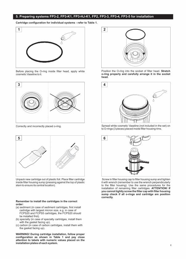
5. Preparing systems FP3-2, FP3-K1, FP3-HJ-K1, FP2, FP3-3, FP3-4, FP3-5 for installation
Spread white cosmetic Vaseline (not included in the set) on to O-rings (3 pieces) placed inside filter housing rims.
4
6
Screw in filter housing cap to filter housing sump and tighten it with wrench (remember to use the wrench perpendicularly to the filter housing). Use the same procedures for the installation of remaining filter cartridges. ATTENTION! If you cannot tightly screw the filter cap with filter housing sump check if all o-rings and cartridge are position correctly.
5
Unpack new cartridge out of plastic foil.
Place filter cartridge inside filter housing sump (pressing against the top of plasticstem to ensure its central location).
Remember to install the cartridges in the correct order:
WARNING! During cartridge installation, follow proper configuration as shown in Table 1 and pay close attention to labels with numeric values placed on the installation plates of each system.
(a) sediment (in case of sediment cartridges, first install cartridge with largest micron size, e.g. in case of FCPS20 and FCPS5 cartridges, the FCPS20 should be installed first). (b) specialty (in case of specialty cartridges, install them with the gasket facing up).(c) carbon (in case of carbon cartridges, install them with the gasket facing up).
Cartridge configuration for individual systems - refer to Table 1.
2
Position the O-ring into the socket of filter head. Stretch o-ring properly and carefully arrange it in the socket head.
1
Before placing the O-ring inside filter head, apply white cosmetic Vaseline to it.
3
Correctly and incorrectly placed o-ring.
6

FCPS5-AQM
FCCBL-AQM
-
-
-
-
-
-
-
-
- - AIFIR1000-
Housing 1
Housing 2
Housing 3
Table 1. Cartridge configuration for individual systems
FP2
FCPS5
FCCBKDF
FCCST2
FP3-HJ-K1
FCPS5FCPS20
FCCST2
FCPS5 FCCBKDF
FCCBL
FP3-K1FP3-2
FCPS5-AQM FCPS5-AQM FCPS5-AQM
FCCST-AQM FCCST-AQM FCCST-AQM
FCCBL-AQM FCCBL-AQM FCCBL-AQM
FP3-3 FP3-4 FP3-5
TLCHF-2T TLCHF-FP TLCHF-FP
Prior to system installation, first install a : UF membrane
Unpack UF membrane from the foil and take out plugs from both ends.
In the under counter system, install UF membrane by placing it in the brackets mounted to the installation plate.WARNING! While installing UF membrane, remember to keep the proper direction of water flow (indicated by an arrow on membrane sticker).
5. Preparing systems for installation: systems equipped w UF membrane 2" (clear housing PET)1. ith
1 2
7
In-line filter cartridge 1
In-line filter cartridge 2
Using flexible tubing (coming out of OUT elbow), connect UF membrane with the system.
WARNING! UF membrane is soaked with a special conserving solution.
Install the cartridge in the direction of flow, then rinse it for several minutes before use. Use only with water microbiologically safe and adequately disinfected.
3

1
1
2
2
8
5.2 . Preparing FP3-4 system for installation: UF membrane installation
Prior to system installation, first install a hollow fiber membrane:
Prior to system installation, first install a UF membrane:
Use tubing to connect filtration system (start from elbow OUT) with UF membrane.
WARNING! UF membrane is soaked with a special conserving solution.
Install the cartridge in the direction of flow, then rinse it for several minutes before use. Use only with water microbiologically safe and adequately disinfected.
Remove plug-in from the inlet connector and UF membrane outlet.
Remove plug-in from the inlet connector of UF membrane and from the inlet connector of filter cartridge AIFIR1000.
5.3. Preparing FP3-5 system for installation: UF membrane installation
Use tubing to connect filtration system (start from elbow OUT) with UF membrane.
WARNING! UF membrane is soaked with a special conserving solution.
Install the cartridge in the direction of flow, then rinse it for several minutes before use. Use only with water microbiologically safe and adequately disinfected.

Screw chrome-plated adapter onto the shut-off valve to allow easy SEWBV1414 valve installation and its easy opening and closing.
Remember to place rubber gaskets in between the connections. WARNING!
Wind a few layers of Teflon Tape TAS0003 on shut-off valve adapter SEWBV 1414.
3 4
6. System Installation - Stage I
WARNING! Manufacturer is not responsible for any damages that result from improper installation or use of system. System installation should be performed only in temperatures above 2°C (35.6°F).
Unscrew flexible tubing from the shut-off valve (or the adapter).
Between the shut-off valve and flexible tubing is a rubber gasket - be sure not to lose it.WARNING!
Shut off cold water supply valve.
1 2
5 6
Screw SEWBV1414 valve into chrome-plated adapter FT06.
Connect other end of flexible tubing to the system.
Put the nut on flexible tubing and connect it with SEWBV1414 valve - push the tubing all the way into the valve and tighten the nut
WARNING! To seal threaded connections, always use Teflon tape during installation (does not concern threads for plastic and faucet nuts).
7
9

6.1. System Installation Option II - Wall Faucet
Unscrew sink faucet from the wall.Shut off water supply valve.
2
Wind a few layers of Teflon Tape TAS0003 on shut-off valve adapter SEWBV 1414.
Screw chrome-plated adapter FT07 onto cold water pipe to allow easy SEWBV1414 valve installation and its easy opening and closing.
Remember to place rubber gaskets in between the connections. WARNING!
43
Screw SEWBV1414 valve into chrome-plated adapter FT07.
Put the nut on flexible tubing and connect it with SEWBV1414 valve push the flexible tubing all the way into the valve and tighten the nut.
Screw chrome-plated adapter FT07 on hot water pipe.WARNING! Remember to place rubber gaskets in between the connections.
Screw sink faucet with chrome-plated adapters.
5 6
87
1
10

Connect other end of flexible tubing with IN elbow of the system.
9
WARNING! To seal threaded connections, always use Teflon tape during installation (does not concern threads for plastic and faucet nuts).
1) Drill an opening 12mm in kitchen counter or kitchen sink (in case of enamel sinks the manufacturer recommends drilling openings in the structure supporting sink).2) On threaded faucet extension [1], first put on cover plate [2], and then rubber gasket [3].3) Secure the faucet in the drilled sink/counter opening.4) Underneath the sink, put the rubber [5] and metal [6] washers on the faucet extension [4], and tighten with metal nut [7]. 5) Install flexible tubing supplying water and connecting faucet with the system: a) put the tubing [11] through the metal nut [10] and plastic tightening ring [9], b) put the insert [8] into the tubing, c) push flexible tubing (all the way) into the faucet extension [4] and tighten it (by hand!) with the metal nut [10].System FP2, FP3-2, FP3-K1, FP3-36) Push otherSystem FP3-HJ-K1, FP3-47) Push other end of flexible tubing 1.5 cm (0.6 in) deep into the connector of UF membrane's housing. System FP3-58)
end of flexible tubing with (OUT) elbow of the system.
Push the other end of tubing 1.5 (0.6 in) cm into the connector which attached to filter cartridge AIFIR1000
7. Systems Installation - Stage II - FXFCH, FXFCH5, FXFCH17-C Faucet Installation
Fig .1
Faucet Installation Kitchen Counter
COUNTER TOP
1
2
3
4
5
6
7
8
9
10
11
FP2, FP3-2,FP3-K1, FP3-3
FP3-5FP3-HJ-K1, FP3-4
WARNING! To seal threaded connections, always use Teflon tape during installation (does not concern threads for plastic and faucet nuts).
11

8. Filtration Cartridges
Dimensions
FCCST2 two-stage, speciality type iron removing and water softening filter cartridge lowers concentration of iron, reduces water hardness by exchanging ions of calcium and magnesium into ions of sodium.
FCCB Water conditioner filter cartridge FCCB contains a blend of coconut shell and bituminous carbons in the ratio 75/25. It has increased water refining properties and improving the taste of water. Removes chlorine from water and organic substances causing odor and taste of water.
FCCST Specialty type ionizer. The filter cartridge reduces water hardness by exchanging ions of calcium and magnesium into ions of sodium.
FCCBKDF three-stage, specialty filter cartridge made of activated ®
carbon, KDF filtration media and polypropylene fibers. Removes mechanical impurities (sand, rust, etc.), chlorine, organic substances, pesticides, phenol, benzene, hydrogen sulfide. Lowers concentration of heavy metals such as: mercury, lead, cadmium, arsenic, etc.
TLCHF-2T removes mechanical impurities such as rust, sand, silt, suspended solids and some bacteria and viruses. Offered in the new, transparent PET housing.
UF membrane
TLCHF-FP UF membrane removes mechanical impurities such as rust, sand, silt, suspended solids and some bacteria and viruses.
9 7/8” x 2 1/2”(25,6 cm x 6,2 cm)
9 7/8” x 2 1/2”(25,6 cm x 6,2 cm)
9 7/8” x 2 1/2”(25 cm x 6,9 cm)
9 7/8” x 2 1/2”(25 cm x 7,1 cm)
9 7/8” x 2 1/2”(25 cm x 7,1 cm)
9 7/8” x 2 1/2”(25 cm x 7,1 cm)
10,8” x 2”(27,4 cm x 6,1 cm)
10,8” x 2”(27,5 cm x 5 cm)
10,8” x 2”(27,4 cm x 6,1 cm)
12” x 2 1/2”(30,4 cm x 6,5 cm)
Cartridge Type Description / Filtration Stage Longevity*
6 - 12 months
3 - 6 months
3 - 6 months
3 - 6 months
3 - 6 months
3 - 6 months
3 - 6 months
6 - 12 months
6 - 12 months
3 - 6 months
* Depends on amounts of filtered water, its quality and level of contamination.
Before the first use of the system and after cartridge replacement, perform system flushing process. Flush the system for several minutes before use. Use only microbiologically safe and adequately disinfected water. After completion of the above operations, filtered water can be consummed.
WARNING! All systems are compatibile with the set of FP3-CRT, FP3-K1-CRT, FP3-CRT-AQM filter cartridges.
WARNING! Filter cartridges are not subject to complaint at the time of:- after opening protective packaging,- after first use of filter cartridges.
PS20 Sediment, cold water cartridge for 10” housing. Designed for pre-filtration of tap and general-use water prior to the main filtration process. Cartridge stops sand, rust particles, sediments and impurities carried by water, and is made of polypropylene strings wound in layers. Layer density increases towards the core of cartridge assuring excellent filtration results.
PS5/FCPS5-AQM Sediment, cold water cartridge for 10” housing. Cartridge stops sand, rust particles, sediments and impurities carried by water, and is made of polypropylene strings wound in layers. Layer density increases towards the core of cartridge assuring excellent filtration results.
FCCBL/FCCBL-AQM Fertilizing cartridge. Contains the sitered carbon with high absorptive abilities of chlorine and organic substances contained in water. The sintered carbon has a large active surface and high efficiency of water filtration.
AIFIR1000 2” Ionizer AIFIR1000 regulates body's pH factor and helps to detoxify body (ionized water is an excellent detoxifying agent).
12

9. Cartridge replacement in the following systems: FP2, FP3-2, FP3-3, FP3-K1, FP3-HJ-K1, FP3-4, FP3-5
Close your water supply valve. Open faucet valve to release pressure build-up in the system.
1
3
Unscrew filter housing sump from filter cap by hand or using wrench (FXWR1-BL). (Remember to use wrench perpendicularly to the filter housing). Remove old filter cartridge.
2
Remove filter cartridge out of plastic foil and place it inside filter housing sump (pressing against the top of plastic tang to ensure its central location).
4
Lubricate filter housing o-rings, next turn the system 180 degree and lubricate filter cap o-rings.ATTENTION! Water may leak out of filter housing 2 and 3.ATTENTION! Wash your hands thoroughly after completing the installation.
13
Screw filter housing sump with filter cap using wrench (remember to use the wrench perpendicularly to the filter housing). Use the same procedures for the installation of remaining filter cartridges.ATTENTION! If you cannot tightly screw in the filter cap with filter housing sump check if all o-rings and the cartridge are situated correctly.
5
Slightly open filter faucet and next gradually open your water supply valve to fill filter housings with fresh water and release air from the system thru the faucet.ATTENTION! After each filter cartridge replacement procedure, all filters must be flashed out with running water for at least 5 minutes. Next do not use the system for 5 to 6 hours – during this time system seals and activates its components. Filtered water can be safely consumed after this process is completed.
6
WARNING! Before the first use of the system and after cartridge replacement, perform system flushing process. Flush the system for several minutes before use. Use only microbiologically safe and adequately disinfected water. After completion of the above operations, filtered water can be consummed..

10. UF membrane replacement: FP3-4
Shut off water supply valve. Open filter faucet to release pressure from the system.
Push in the flange and pull out flexible tubing. Remove UF membrane housing from mounting clips.
3 4
1 2
14
Unpack new UF membrane out of plastic foil and remove end plugs.
Unscrew inlet and out let connectors from the UF membrane.
Remove all layers of old Teflon tape and apply mutliply layers of new one.NOTE! Ensure that Telflon tape is winded in the opposite direction to the direction connector will be installed.
5
7
6
8
Connect inlet and outlet connectors to the housing of new UF membrane.NOTE! Do NOT remove elbow connector after the installation has been started. Stopping and removing (unscrewing) the element may result in inadequate connection and water leak.

Insert flexible tubing (all the way) into both ends of UF membrane.
! Check if inlet/outlet tubings are correctly and firmly connected. Make sure the tubing is not bent.NOTE
Open water supply valve.
11
9 10
Push in membrane housing into mouting clips.WARNING! While installing UF membrane, remember to keep the proper direction of water flow (indicated by an arrow on membrane sticker).
WARNING! UF membrane is soaked with a special conserving solution.
Install the cartridge in the direction of flow, then rinse it for several minutes before use. Use only with water microbiologically safe and adequately disinfected.
15
10.1. UF membranes replacment: FP3-HJ-K1
3 4
1 2
Shut off water supply valve. Open filter faucet to release pressure from the system.
Push in the flange and pull out flexible tubing. Remove UF membrane housing from mounting clips.
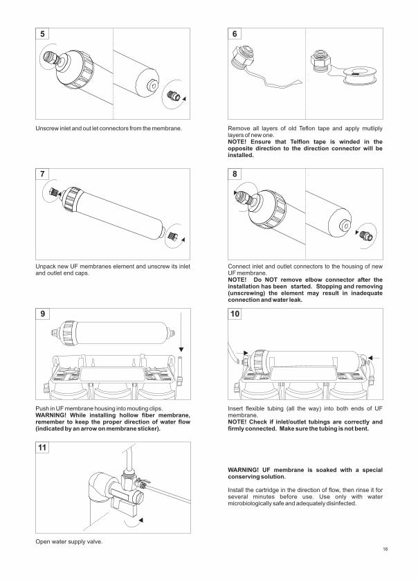
Unscrew inlet and out let connectors from the membrane. Remove all layers of old Teflon tape and apply mutliply layers of new one.NOTE! Ensure that Telflon tape is winded in the opposite direction to the direction connector will be installed.
6
Unpack new UF membranes element and unscrew its inlet and outlet end caps.
5
7
Connect inlet and outlet connectors to the housing of new UF membrane.NOTE! Do NOT remove elbow connector after the installation has been started. Stopping and removing (unscrewing) the element may result in inadequate connection and water leak.
8
16
11
9 10
Push in UF membrane housing into mouting clips.WARNING! While installing hollow fiber membrane, remember to keep the proper direction of water flow (indicated by an arrow on membrane sticker).
Insert flexible tubing (all the way) into both ends of UF membrane.
! Check if inlet/outlet tubings are correctly and firmly connected. Make sure the tubing is not bent.NOTE
Open water supply valve.
WARNING! UF membrane is soaked with a special conserving solution.
Install the cartridge in the direction of flow, then rinse it for several minutes before use. Use only with water microbiologically safe and adequately disinfected.

10.2. Replacing UF membrane and filter cartridge AIFIR1000 in FP3-5 system
1 2
3 4
Shut off water supply valve. Open filter faucet to release pressure build-up in the filter.
Hold filter cartridge AIFIR1000 and UF membrane and remove them from the system.
Disconnecting UF membrane and filter cartridge AIFIR1000 from the system. First, disconnect tubing from the inlet connector attached to hollow fiber membrane. Second, disconnect tubing connecting filter cartridge AIFIR1000 with filter faucet.
Disconnecting UF membrane and filter cartridge AIFIR1000. First, press outside ring of the inlet connector symmetrically and next pull out the tubing. CAUTION! Tubing is placed inside of inlet connector which is attached to AIFIR1000. Take special care to prevent damage to the tubing.
17
5 6
7 8
Remove UF membrane from mounting clips installed on AIFIR1000.
Unscrew inlet and outlet connectors attached to UF membrane housing.
Unscrew inlet and outlet connectors from AIFIR1000. Remove old Teflon tape from the connectors. Wind several layers of new Teflon tape on each connector. NOTE! Wind Teflon tape in counter-clock direction.

18
9 10
11 12
Screw-in connectors into new UF membrane housing. CAUTION! Don't backtrack during screwing in the connectors. Backtracking connectors may result in compromising the connection seal and water leaks.
Unpack UF membrane and remove plug-ins.
Unpack new filter cartridge AIFIR1000 and remove plug-ins from the inlet and outlet.
Move mounting clips from old to the new filter cartridge AIFIR1000.
13 14
Screw in connectors into new filter AIFIR1000 housing. CAUTION! Connect inlet connector (with tubing) to the cartridge inlet. Next, connect outlet connector (without tubing) to the cartridge outlet. CAUTION! Don't backtrack during screwing in the connectors. Backtracking connectors may result in compromising the connection seal and water leaks.
Attach hollow fiber membrane with mounting clips which are installed om AIFIR1000 filter cartridge. CAUTION! During the installation pay special attention to correct water flow direction. Correct water flow direction is indicated by an arrow placed on the sticker of the cartridge.

15
17
16
18
Connecting filter cartridge AIFIR1000 and UF membrane. First, connect tubing coming out of AIFIR1000 inlet with UF membrane outlet connector. CAUTION! During the installation pay special attention to the tubing, prevent it from being bended or damaged.
Connect filter cartridge AIFIR1000 and UF membrane by placing UF membrane into mounting clips, which are already installed on the system mounting bracket. CAUTION! During the installation pay special attention to correct water flow direction. Correct water flow direction is indicated by an arrow placed on the sticker of the cartridge.
Using tubing connect elbow connector OUT of the filtration system with inlet connector of UF membrane. Connect filter faucet tubing with AIFIR1000 connector. CAUTION! During the installation pay special attention to the tubing, prevent it from being bended or damaged.
Open water supply valve.
19
Related Documents


