Hytera Customer Service Express ISSUE 12 Dec, 2012 www.hytera.com

Welcome message from author
This document is posted to help you gain knowledge. Please leave a comment to let me know what you think about it! Share it to your friends and learn new things together.
Transcript

Hytera Customer Service Express
ISSUE 12 Dec, 2012 www.hytera.com

News and Events
Correspondence Column
Repairing Case Section
1
P2 Hytera Return Material Authorization (RMA) Policy
P4 PD78X/PD70X No Rx Audio on External Microphone/Speaker Accessory
Repair Case
P7 TM610 Can't Read And Write Repair Case
P8 Troubleshooting of TM800 Cannot Power on
P11 A Typical Case for Repairing TC-700 Bad Receiving Problem
P13 PD78X Common Malfunction Analyze and Repair
P15 MD78X Low Rx Sensitivity Repair Case

Hytera RMA policy has been updated according to the current business requirements. Below are the two points that distinguishes the new RMA policy from the old one. 1. The roles as of customer and Hytera service manager and their functions are more specified. 2. The RMA process (FIG.1) is more simplified for customers to understand and to follow. RMA Flowchart V1.0
002
Serv
ice
Man
ager
001
Cus
tom
er
Start 010 Customer apply for an RMA
020 Verification
040 Arrange shipment for
malfunction goods to Hytera
050 Follow the shipment before
goods arrive in Hytera HK
060 Receive goods End
End
N
030 Send approved RMA form back to
customerY
FIG. 1 What also need to be emphasized here are packaging, delivery charges and address of returned goods. 1. Packaging 1.1 Original packaging should be used if available to minimize the risk of shipment damage. Board products must be packed in antistatic plastic bubble bags to avoid ESD (electrostatic discharge) damage and physical damage. If the goods are damaged in transition from customer side to Hytera due to improper packaging, Hytera reserves the right to determine whether or not the returned products are repairable. 1.2 An RMA Form which is with RMA# and Hytera GCSC official seal must be put in the package when the goods are returned. 1.3 Customer shall keep a record of shipping documents in case the shipment is lost. Customer is responsible for the product until it is received by Hytera. 2. Delivery Charges Freight and any other cost related to shipment of when the product returns to Hytera shall be prepaid by customer; Freight and any other cost related to shipment of when the product returns to customer shall be prepaid by Hytera. 3. Address of Returned Goods We recommend customers to confirm address with service manager before returning goods. For further details, please go to www.hytera.com or contact Hytera Overseas Service Department. Email address: [email protected] Hotline: +86-755-86137081
Hytera Return Material Authorization (RMA) Policy Update
2
News and Events

Correspondence Column
A Tp
Correspondence Column
Started from Hytera Customer Service Express #12, Correspondence Column will
be newly open to customers of Hytera. It is the platform for customers of Hytera to share their repairing experience or anecdotes in repairing Hytera products and to discuss technical issues with Hytera technicians in global. The technical articles which are contributed from customers of Hytera will be published in Correspondence Column after the verification of Hytera. Emails from customers which are about technical and repairing cases will also be sorted and filtered and to be published as technical knowledge sharing. Correspondence Column belongs to customers of Hytera. It is a shortcut for you to get closer with Hytera and to connect with those who are so dedicated to radio repairing work and technics as you do. Looking forward to your works! Any further concern, you are welcome to send letters anytime to [email protected].
Special thanks to Luis Hochnadel(Left), who has
contributed the first technical article PD78X/PD70X No Rx Audio on External Microphone/Speaker Accessory Repair Case to Correspondence Column. Luis is a senior technician. He has been serving for a Hytera aftersales service station for years.
Editor’s Words
3
Luis and Adam

Correspondence Column
PD78X/PD70X No Rx Audio
on External Microphone/Speaker Accessory Repair Case
1. Fault description PD78X/PD70X radio works fine, when external microphone/speaker is connected, no rx audio thru the accessory. 2. Analysis a. From fault phenomenon we can see, it is a radio failure. b. The main reason to cause this audio failure it could be at first sight the internal/external audio
switch circuit. 3. Typical maintenance case
RADIO TYPE FREQUENCY RANGE FIRMWARE VERSION
PD78X/PD70X 400-470 MHz V 4.05
Case study • FAULT PHENOMENON This PD78X/PD70X radio works OK, but when an accessory microphone/speaker is externally connected, no audio is going thru to activate external speaker. PTT and TX audio are OK. • FAULT ANALYSIS After checked speaker on external accessory, found that it is OK. Problem resides in the radio. • DETECTING STEPS 1) Disassemble radio and locate connector J1601 (50 pins) that connects front case with main
board (FIG. 1).
FIG. 1
By Luis Hochnadel
4

Correspondence Column
2) With accessory microphone/speaker connected to the radio, check the audio signal that goes to the external speaker, pins 45 and 47. If there is no audio on these pins, problem could be related to the audio switching circuit Q802 and Q801, that select which amplifier is going to deliver the audio either internally or externally. See FIG. 2.
3) If audio signal on these pins 45 and 47 are OK, problem could be caused by an EXT-BAT + failure, see FIG. 3
FIG. 3
FIG. 2
5

Correspondence Column
Please refer to FIG.1 pin 46, it must be approximately + 7 Volts, if very low voltage or 0 Volts, problem is on Q605 or EXT-BAT + circuit ( FIG. 3 ). Replace Q605, pin 46 with accessory connected will show + 7 Volts, Problem solved, Q605 is shown on FIG. 4
FIG. 4
6

Repairing Case Section
TM610 Can’t Read and Write Repair Case 1. Fault Description
Connect the mobile radio and PC with programming cable, but PC can’t read and write frequency by programming software. 2. Fault Reason Analysis 1) For software problem, there are some possibilities: programming software isn’t matched, PC
serial port setting isn’t right or PC serial port is taken up and so on. 2) For the hardware problem, it is mainly caused by serial port communication circuit, you have to
check TXD, RXD circuit and component around. 3. Specific maintenance cases
Case 1 Radio Type Frequency Range Firmware TM610 400—470MHZ V2.04.04
Fault Phenomenon This mobile radio can power on and off normally, but it can’t transmit and be programmed by software. Fault Analysis
Analyzing from the fault phenomenon, because it can’t transmit, we doubt it is hardware problem, speaker microphone socket’s PTT control pin is the same pin with TX programming port Detection step(see FIG.1) 1) Power on the radio, programming cable is rightly connected, PC informs the error information:
error connection, please check all connections. 2) Check speaker microphone socket, find the 5th pin moved obviously, the 5th pin is just PTT signal
and serial communication pin. 3) After changing speaker microphone socket J301, it can transmit and program normally, the fault is
solved. 4. Summarization The radio can’t TX and program because of bad connection of speaker microphone socket’s pin. Notice: PTT and TXD share one circuit in common.
FIG. 1
By Eric Liu
7

Repairing Case Section
Troubleshooting of TM800 Cannot Power on
1. Fault Description a. There is no reaction (no display/no alert tone when press power on button) when connect the
power supply with TM800. b. Connect the power supply with TM800, the display shows “NO DATA”. 2. Analysis a. From the fault phenomenon, the TM800 radio have problem of can not power on. b. The main reason of this radio software failure includes that program breakdown or data lost. We
can solve this problem by the following method that using the Burning application, reprogramming, resetting, etc.
c. The main reason of this radio hardware failure includes that power supply circuit, protection circuit, CPU controlling circuit, etc.
3. Typical Maintenance Case
Case No.1 Radio Type Frequency Range Firmware Version TM800 400-470MHz V2.1.12
• Fault Phenomenon
Connect the power supply with this TM800, found there is no display, no alert tone, even press the power on button. The DC power supply shows nothing.
• Fault Analysis
The fault phenomenon shows that the radio cannot power on, we need to check the power supply circuit first, it probably the power supply cable damaged, fuses of Voltage protection circuit damaged, or power switch circuit failed.
• Detecting Steps (Refer FIG 1)
1) From the fault phenomenon that there is no reaction when connect the power supply with TM800, we suspect the possibility of hardware problem is much than software problem. So we need detect the hardware circuit first.
2) Using the Multimeter to check the power supply. The result is normal.
3) When power supply +B voltage, TM800 radio will have 9 groups voltage if it is works well. (Refer FIG 1)
By Elsie Wang
8

Repairing Case Section
4) Figure 2 shows the TM800 power supply switch circuit, Q142 is the power supply switch control tube. The testing power supply input +B, the output from E pole of Q142 is 13.8V, normal. B pole output 13.5V, normal. C pole output 0V, abnormal, the voltage output from C pole should be 13.6V. So we suspect the Q142 is damaged.
5) Replace Q142, connect power supply to power on the radio, detect that the C pole of Q142 output 13.6V, and the radio back to normal and works well, problem solved.
FIG. 2
FIG. 1
9

Repairing Case Section
• Summary This is power supply problem, the reason that TM800 cannot power on is the power supply switch diode Q142 damaged.
Case No.2: Radio Type Frequency Range Firmware Version
TM800 350-390MHz V1.5.06
• Fault Phenomenon
Connect the power supply and power on TM800, the display shows “NO DATA”, and there is not alert tone output.
• Fault Analysis
The fault phenomenon shows this is the problem is radio can not power on, and it is probable the software problem.
• Detection Steps 1) Connect the radio and PC with programming cable, reprogram the radio with factory default informatin, if the problem still exsit, move to step 2. 2) Power on the radio while pressing PF6 button to enter the programming mode, enable the reset function, and then turn off the radio. Power on the radio while Pressing PF2 button to enter resetting mode; then press [PF3] to enter Adjustment Mode;then press[PF4] to enter Model Set Mode; ”DESTINATION” and the model No. are displayed; then turn the Selector Knob to choose model 0-6.
Model No. Frequency Range Model No. Frequency Range 0 V(136-174MHZ) 4 U3(440-490MHZ) 1 U2(450-512MHZ) 5 U4(480-526MHZ) 2 U5(350-400MHZ) 6 U6(380-430MHZ) 3 U1(400-470MHZ) 7 U7(450-520MHZ)
Then Press [PF6] to confirm. LED will glow orange and LCD displays ”Wait a second…” Press [PF3] to return to Test Mode. After resetting, power on the radio again, radio back to normal and works well. Problem solved. 3) Summary This possible reason to cause the power on problem is when we do the programming, the PC/programming cable/power supply got connectivity problem somehow, it would cause the software error or the data in memorizer damaged.
10

Repairing Case Section
A Typical Case for Repairing TC-700 Bad Receiving Problem
1. Fault description a. The communication distance of broken TC-700 is obviously closer than other normal TC-700
radios under same using circumstances. b. The receiving sensitivity is lower than -118dBm when we test under analyzer HP8921. 2. Analysis a. The major reasons caused by software problem: The frequency customer wrote is over the radio’s
default frequency band, wrong frequency band etc. You can try to refresh the radio’s firmware, reprogramming and reset the radio to fix the software problem.
b. The circuit of hardware problem: RF receiving circuit\ IF receiving circuit. The wear parts including: 450KHz second IF filter\49.95MHz first IF filter\ IF demodulation IC TA31136&BA4116\low noise amplifier\mixer.
3. A Typical Case of how to fix the TC-700 bad receiving problem
Model Frequency Firmware Version TC-700 400-470MHz V2.17
• Fault Phenomenon
The communication distance of This TC-700 is obviously closer than other normal TC-700 radios under same using circumstances.
• Analysis
This radio’s receiving capacity become lower after a period of time using. Normally, the receiving sensitivity of TC-700 should be higher -118dBm, but this radio’s receiving sensitivity is only -80dBm under analyzer’s test. We can use high frequency signal injection method to check which part of the circuit hardware is broken.
• The Repairing process
1) Connect the radio to computer’s Hytera programming software. Read the radio and we found the frequency of current channel; it is 435.55MHz, no signaling on this channel.
2) Use an analyzer to inject 49.95MHz /-100dBm RF signal to right side of XF203(the first IF filter),observe the indicator of TC-700, if indicator is green, and the speaker has audio signal voice output, that means the circuit after XF203 is OK, the broken circuit is before XF203, which is the LNA circuit and mixer circuit.
3) Use an analyzer to inject 435.55MHz /-100dBm RF signal to right side ofC243( mixer input), if indicator is green, and the speaker has audio signal voice output, that means the mixer circuit is OK.
4) Use an analyzer to inject 435.55MHz /-115dBm RF signal to right side of C254.We found the indicator is off and there is no voice output from the speaker. We think the problem is caused by Q207 and its circuit.
By Viki Zhang
11

Repairing Case Section
5) Test Q207 C pole voltage, it is 4.8V- OK; test its B pole, it is 0V.-not OK. Normally the B pole should have 0.7V output voltage. We think the Q207 might be broken.
6) Replace Q207, test B pole voltage, it is 0.7V now. Test the receiving sensitivity again, it is -119dBm. The problem is solved.
IF signal Input Mix signal input Q207 C pole voltage:4.8V
Q207 B pole voltage:0.7V
RF signal input
• Summary This radio’s faulty reason is the Q207 is broken, its voltage is wrong to let the sensitivity of the radio became low.
12

Repairing Case Section
PD78X Common Malfunction Analyze and Repair
1. Screen Blank after Power On
1) Description After power on, the LCD display blank (Nothing shows on the screen).
2) Analyze This problem is mainly caused by the program disorder when initializing.
3) How to repair The radio will be back to normal after upgrade to the newest version. You can get the newest version of upgrade software from our official website: http://www.hytera.com/ 2. No Sound after Power On
1) Description When power on or RX, there is no sound from the speaker.
2) Analyze This problem is mainly caused by the loosing cable which is used to connect the RF board to the radio case.
3) How to repair Disassemble the radio and re-install the cable, please make sure the cable is connected well. Please refer to the following picture about the cable.
3. Automatic Restart after Power On
1) Description When turn on the radio or the radio is running, sometimes the LCD screen will grow fainter and fainter, and then power off, after 1 or 2 seconds, will automatic restart.
2) Analysis The battery of PD78X is loose from the main radio (There is a tiny slot between the battery and the main radio), this may cause poor contact between the battery connector and the battery.
By Warren Liu
13

Repairing Case Section
3) How to repair Add silicone rubber pad on the left and right top slot of the battery, this can solve the looseness between the battery and the battery connector. a. After added the silicone rubber pad on the battery:
b. The silicone rubber pad description is as follows:
Material Description Picture 7500533000000
Anti-loosening silicone rubber pad for PD780 thick battery 00
(RoHS)
c. If you need the silicone rubber pad, you can contact our spare parts department or our service
engineer.
14

Repairing Case Section
MD78X Low Rx Sensitivity Repair Case
By Warren Liu
1. Fault Phenomenon
1) MD78X RX communication range is very close, but the TX communication range is normal.
2) Use the analyzer to test MD78X’s RX sensitivity, the value is less than -119dbm (e.g. -110dbm).
2. Cause Analysis • Reason 1: Software Malfunction
a. Programming software wrong configuration. b. The radio’s firmware wrong, need to refresh the firmware. • Reason 2: Hardware Malfunction a. Main PCB board malfunction: RX high-frequency amplifier circuit, RX IF circuit. The easily
broken components are: First IF filter, high frequency amplifier tube. 3. Repair Case
Model Frequency Range Firmware Version MD780 400-470MHz R3.05.10.001 • Fault Phenomenon
MD780 RX sensitivity is very low. The analog channel’s RX sensitivity is -100dbm, but the TX is normal.
• Cause Analyze After using the radio for a period time, the radio will have some low RX sensitivity problem, this problem should be caused by the hardware fault, such as high-frequency amplifier circuit fault, IF circuit fault. When the radio is normal, the RX sensitivity should be better than -119dbm, but after testing by the analyzer, the radio’s sensitivity is -100dbm, this is abnormal. We can use the signal injection method to find out which part have problem.
• Test Procedure 1) Use the programming software to read the radio, check whether the squelch level
setting is OK. Refer to FIG 1.
15

Repairing Case Section
2) Refer to FIG 2, Use the analyzer from test point TP6109 which is on the right side of Z6100 (First IF filter), input a 73.35MHz, -100dBm signal, we can see that the radio’s LED light turns green, and the speaker have sound. From the above test, we can judge that the circuit after the Z6100 (include Z6100) is OK, the malfunction is before Z6100: the high-frequency amplifier and mixing circuit.
FIG. 1
IF Signal Input Test Point TP6109
FIG. 2
Mixing Circuit Input Test Point
16

Repairing Case Section
3) Refer to Fig 2, Use the analyzer from the 4th pin of T6100 (RX signal input) input a RX signal: the frequency is the current channel RX frequency, signal amplitude is -100dBm, and we see that the radio’s LED light turns green, the speaker have sound. From the above test, we judge that the mixing circuit is working fine. 4) Refer to Fig 3, Use the analyzer from the 2nd pin of Q6102 (high-frequency amplifier tube) input a RX signal: the frequency is the current channel RX frequency, signal amplitude is -115dBm, and we see that the radio’s LED light is off, the radio cannot open the squelch, that is abnormal. From above test, we can judge that the high-frequency amplifier circuit have problem, may be the high-frequency amplifier tube is broken.
FIG 3
high-frequency amplifier circuit signal input test
High-frequency amplifier tube Q6102
To Mixing Circuit
5) After replace high-frequency amplifier tube Q6102, test the radio’s RX sensitivity is -119dBm, the radio back to normal, the malfunction is eliminated.
• Summary This radio’s RX sensitivity low is caused by the high-frequency amplifier tube broken. The repair of digital radio is similar to the analog radio, we can also use the signal injection method to find out which part of the circuit have problem.
17

Repairing Case Section
RD98X Power on Slow Repair Case
1. Fault Phenomenon After RD98X connected the power supply, the log “Hytera” stay for about 20 seconds, then go to the main interface.
2. Cause Analyze From the above phenomenon, we can see that the power on last about 20 seconds, which is not normal, normally power on only last about 5 seconds. This problem may be caused by the firmware version is too low.
a) If your version is R2.05/R3.0/R3.05/R4.0/R4.01, you can solve this problem by upgrading. b) If your version is temporary version, you must return your radio back to Hytera for repair.
3. Repair Case
Model Frequency Range Firmware Version RD980 400-470MHz R1.00.00.461 • Fault Phenomenon
After RD98X connected the power supply, the logo “Hytera” stay for about 20 seconds, then go to the main interface. And the repeat action is also very slow.
• Cause Analyze From the phenomenon, this is may be caused by firmware version is too low, need to upgrade
to the newest firmware version. • Solve Procedure
1) How to enter the upgrade mode, please see the pictures as follows:
Hook the hand Mic to the accessory hook.
By Warren Liu
18
Repairing Case Section
Press PTT and don’t release, power on the repeater, until the TX-B LED Light turn red, then the repeater enter into upgrade mode, then use the programming cable connect to the PC.
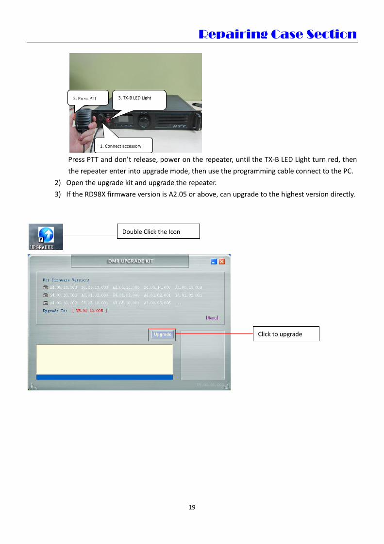
2) Open the upgrade kit and upgrade the repeater. 3) If the RD98X firmware version is A2.05 or above, can upgrade to the highest version directly.
1. Connect accessory
2. Press PTT 3. TX-B LED Light
19
Click to upgrade
Double Click the Icon

Repairing Case Section
• Summary This phenomenon is caused by the firmware too low, that’s why the repeater power on very slowly
and repeats very slowly.
20
The upgrade is finished.

mn
Hytera Customer Service Express Issue12/Dec 2012
www.hytera.com
Address: Hytera Tower, Shenzhen Hi-Tech Industrial Part North, Beihuan RD., Nanshan District, Shezhen, P.R. C
Service Hotline: +86-755-86137081
Email: [email protected] EDITORIAL Editors-in-Chief: Li Yong Executive Editor: Patrick Ren Technical Editor: Sean Xiao/Lancer Liu Editor: Angelia Yong
Publication
Hytera Communications Corporation Limited

Repairing Case Section
Hytera Customer Service Express www.hytera.com
Related Documents