CSE4884 Network Design and Management Lecturer: Dr Carlo Kopp, MIEEE, MAIAA, PEng Lecture 9-10 Packet Network Topology, Design, Modelling and Performance Concepts

© 2006, Monash University, Australia CSE4884 Network Design and Management Lecturer: Dr Carlo Kopp, MIEEE, MAIAA, PEng Lecture 9-10 Packet Network Topology,
Dec 14, 2015
Welcome message from author
This document is posted to help you gain knowledge. Please leave a comment to let me know what you think about it! Share it to your friends and learn new things together.
Transcript
CSE4884 Network Design and Management
Lecturer: Dr Carlo Kopp, MIEEE, MAIAA, PEng
Lecture 9-10
Packet Network Topology, Design, Modelling and Performance Concepts
References Open Systems Interconnection Reference Model (OSI) -
http://en.wikipedia.org/wiki/OSI_model Kopp C., Xterminals and Host Performance, Part 1,
Feature Article, Open Systems Review, October 1994. Kopp C., Xterminals and Host Performance, Part 2,
Feature Article, Open Systems Review, November 1994. Kopp C., An introduction to cable modems,
Cable Modem Technology, Asia/Pacific Open Systems Review, Sydney Australia, August 1996, 60-63, 4pp.
Kopp C., Digital subscriber line technologies - The technical issues, Asia/Pacific Open Systems Review, Sydney Australia, September 1996, 50-51, 2pp.
Kopp C., Networking - A perspective, PPP Protocol, Asia/Pacific Open Systems Review, Sydney Australia, November 1996, 24-28, 5pp.

Overview
Packet network concepts, OSI model TCP/IP Ethernet Systematic design methodology Producing a user load/demand model Producing a traffic model Defining the network topology – part 1

Packet Networks
Data is encapsulated with addressing and status information, and then transmitted across the network.
Network typically uses multiple layers of encapsulation to cross addressing and spatial boundaries.
A typical format for a packet will involve a header containing address and status, a ‘payload’ or carried data, and may include a checksum, Cyclic Redundancy Check (CRC) field, or Forward Error Control (FEC) field.
Within the addressing domain of the protocol used, the packet contains everything required to carry the payload to its destination.
Large and complex networks require multiple protocol ‘layers’ and thus multiple levels of encapsulation.

Protocols
What is a protocol? A protocol is a set of specific rules which define
exchanges of packets between nodes, to effect a specific control or data transmission function.
In packet networks, specific packet structures are typically associated with specific protocols, or parts of protocols.
Protocols commonly involve the exchange of control or status messaging packets. A control or status message is usually acknowledged.
Data transfer packets often include mechanisms for fragmentation, to split big packets into smaller ones, compatible with lower level protocols.

Packet Networks - Stacks
The result is that any networking scheme typically ends up with a heirarchical ‘stack’ of protocols to effect end-to-end transmission of data.
These stacks typically form ‘protocol suites’, examples being TCP/IP, OSI/GOSIP and IBM SNA.
Each protocol has a specific defined function in the stack, and is essential for network operation.
The most commonly used model for describing these layers is the Open Systems Interconnection Reference Model (OSI) model.
The OSI model defines seven layers, each with a specific set of functions.
OSI Model
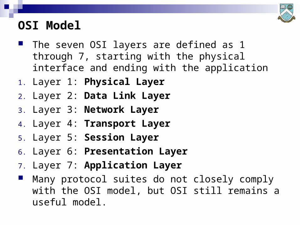
The seven OSI layers are defined as 1 through 7, starting with the physical interface and ending with the application
1. Layer 1: Physical Layer
2. Layer 2: Data Link Layer
3. Layer 3: Network Layer
4. Layer 4: Transport Layer
5. Layer 5: Session Layer
6. Layer 6: Presentation Layer
7. Layer 7: Application Layer Many protocol suites do not closely comply with the OSI
model, but OSI still remains a useful model.

OSI Model - Encapsulation
ERR
SYNC PREAMBLE DATA PAYLOAD POSTAMBLEHEADERCTRLERR
HEADER DATA PAYLOAD
DATA PAYLOAD
CTRLDATA PAYLOAD HEADER
LAYER 4/5
LAYER 6/7
LAYER 1
LAYER 2
LAYER 3
CTRL
SEQ

Layer 1: Physical Layer
Modulation, electrical, optical, radio-frequency and physical definition of the host to network interface.
Modulation converts the digital data representation into a specific signal format imposed on the electrical, optical or radio-frequency channel.
Contention between nodes for the transmission medium is usually handled in the physical layer.
The definition of cables, connectors, and other physical components is part of the physical layer.
The physical later determines most of the characteristics of point-to-point links used in a network.
Physical Layer - Examples
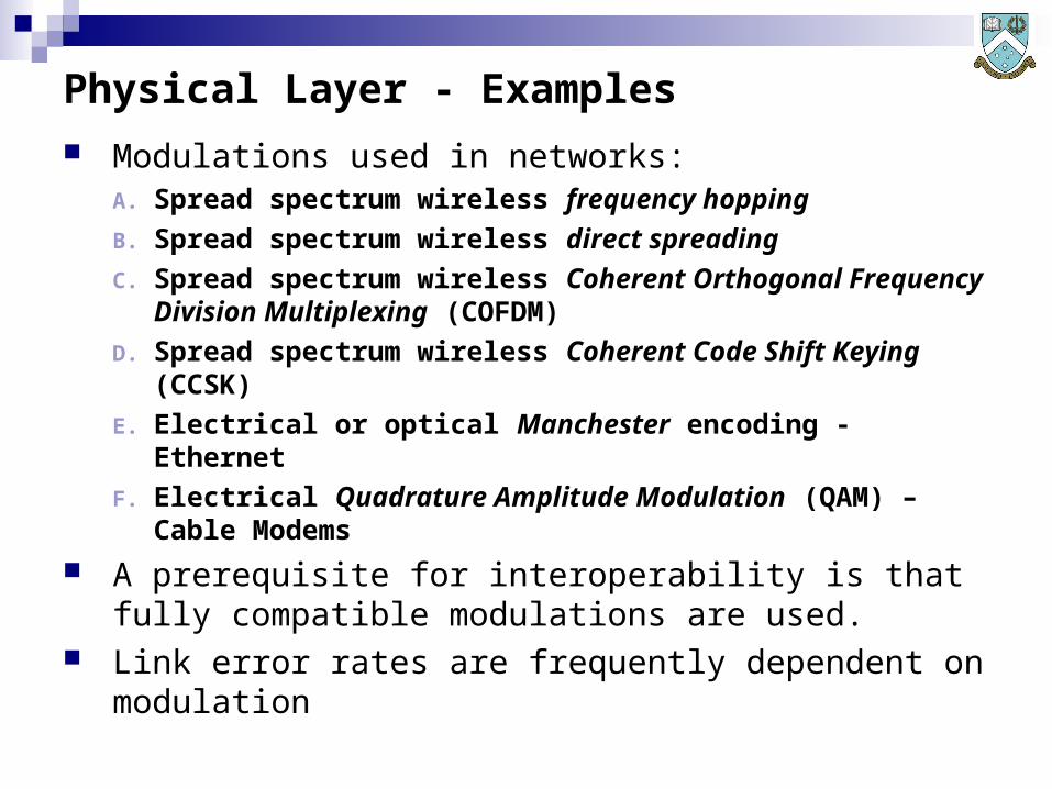
Modulations used in networks:A. Spread spectrum wireless frequency hopping
B. Spread spectrum wireless direct spreading
C. Spread spectrum wireless Coherent Orthogonal Frequency Division Multiplexing (COFDM)
D. Spread spectrum wireless Coherent Code Shift Keying (CCSK)
E. Electrical or optical Manchester encoding - Ethernet
F. Electrical Quadrature Amplitude Modulation (QAM) – Cable Modems
A prerequisite for interoperability is that fully compatible modulations are used.
Link error rates are frequently dependent on modulation
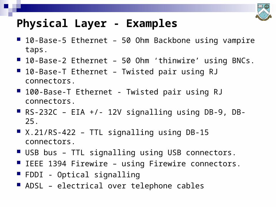
Physical Layer - Examples
10-Base-5 Ethernet – 50 Ohm Backbone using vampire taps.
10-Base-2 Ethernet – 50 Ohm ‘thinwire’ using BNCs. 10-Base-T Ethernet – Twisted pair using RJ connectors. 100-Base-T Ethernet - Twisted pair using RJ connectors. RS-232C – EIA +/- 12V signalling using DB-9, DB-25. X.21/RS-422 – TTL signalling using DB-15 connectors. USB bus – TTL signalling using USB connectors. IEEE 1394 Firewire – using Firewire connectors. FDDI - Optical signalling ADSL – electrical over telephone cables

Layer 2: Data Link Layer Provides a functional / procedural way of transferring
data between network nodes and detecting (and often correcting errors Physical layer transmission errors).
An addressing scheme is used, which is typically hardcoded or preprogrammed in the network interface.
In Ethernet (802.3) networks, the DLL is further subdivided into the Medium Access Control (MAC) layer and the IEEE 802.2 Logical Link Control (LLC) layer.
Transmission protocols designed for DLL are typically strongly optimised for the specific physical layer they operate with.
The DLL thus includes packet structures, and protocols for exchanging packets.
Hubs and switches are layer 2 devices.

Layer 3: Network Layer
The Network layer will provide: A mechanism for transporting data payloads across one
or more datalink layer networks. A mechanism for Quality of Service as required by upper
layers. Fragmentation and defragmentation mechanisms to
accommodate different Layer 2 network packet sizes. Route discovery and route maintenance mechanisms for
the network. Error messaging or delivery management. Routers are layer 3 devices.
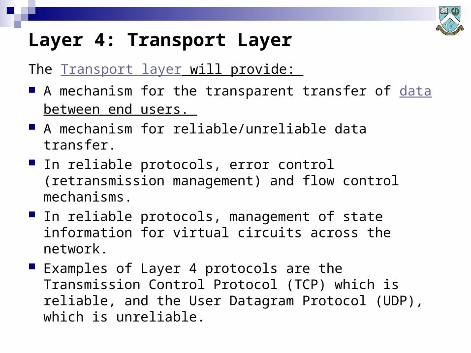
Layer 4: Transport Layer
The Transport layer will provide: A mechanism for the transparent transfer of data
between end users. A mechanism for reliable/unreliable data transfer. In reliable protocols, error control (retransmission
management) and flow control mechanisms. In reliable protocols, management of state information
for virtual circuits across the network. Examples of Layer 4 protocols are the Transmission
Control Protocol (TCP) which is reliable, and the User Datagram Protocol (UDP), which is unreliable.

Layer 5: Session Layer
The Session layer will provide: Control of dialogues or sessions between network
hosts. Establishment, management and termination of
connections between local and remote applications. Possibly duplex or half-duplex operation. Establishment of checkpointing, adjournment,
termination, and restart procedures. Checkpointing and recovery of sessions is often not
implemented. In the TCP/IP suite, session close functions are
performed in TCP.

Layer 6: Presentation Layer
The Presentation layer will provide: Transformation of data formats intended to provide a
standard or common interface for the Application layer. This is necessary to ensure that applications can handle
data which may otherwise be in incompatible formats. Examples include the NFS (Network File System) XDR
( eXternal Data Representation) protocol which handles byte ordering and word sizes, email MIME encoding, data compression, data encryption techniques, IBM EBCDIC to ASCII conversion and vice versa.
Presentation layer functions are often embedded in applications, such as browsers or mailers.
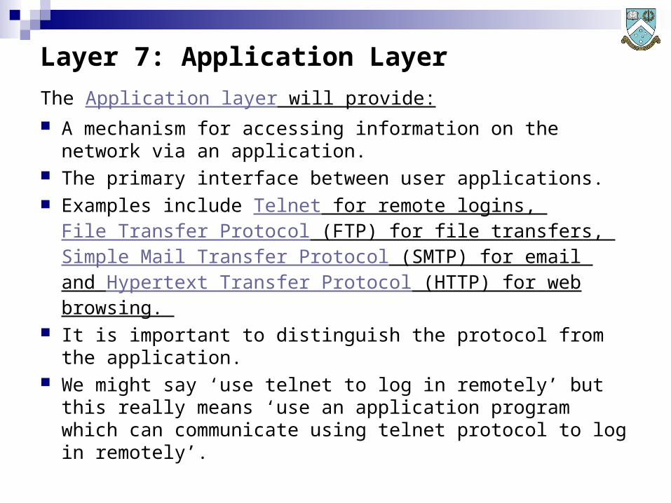
Layer 7: Application Layer
The Application layer will provide: A mechanism for accessing information on the network
via an application. The primary interface between user applications. Examples include Telnet for remote logins,
File Transfer Protocol (FTP) for file transfers, Simple Mail Transfer Protocol (SMTP) for email and Hypertext Transfer Protocol (HTTP) for web browsing.
It is important to distinguish the protocol from the application.
We might say ‘use telnet to log in remotely’ but this really means ‘use an application program which can communicate using telnet protocol to log in remotely’.
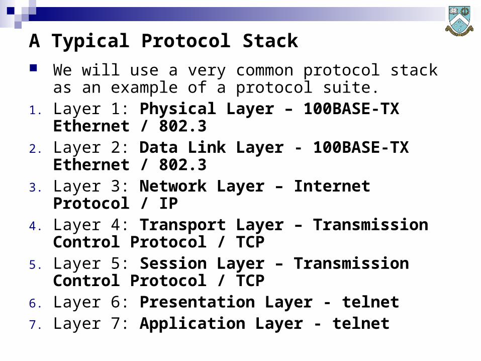
A Typical Protocol Stack We will use a very common protocol stack as an
example of a protocol suite.1. Layer 1: Physical Layer – 100BASE-TX Ethernet /
802.32. Layer 2: Data Link Layer - 100BASE-TX Ethernet /
802.33. Layer 3: Network Layer – Internet Protocol / IP4. Layer 4: Transport Layer – Transmission Control
Protocol / TCP5. Layer 5: Session Layer – Transmission Control
Protocol / TCP6. Layer 6: Presentation Layer - telnet7. Layer 7: Application Layer - telnet
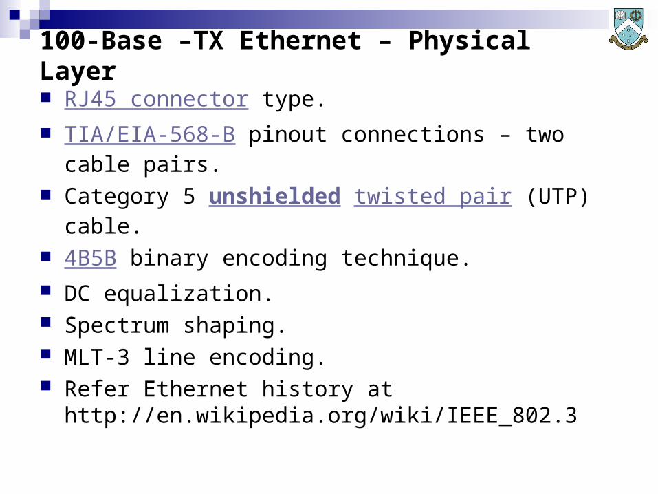
100-Base –TX Ethernet – Physical Layer
RJ45 connector type. TIA/EIA-568-B pinout connections – two cable pairs. Category 5 unshielded twisted pair (UTP) cable. 4B5B binary encoding technique. DC equalization. Spectrum shaping. MLT-3 line encoding. Refer Ethernet history at
http://en.wikipedia.org/wiki/IEEE_802.3
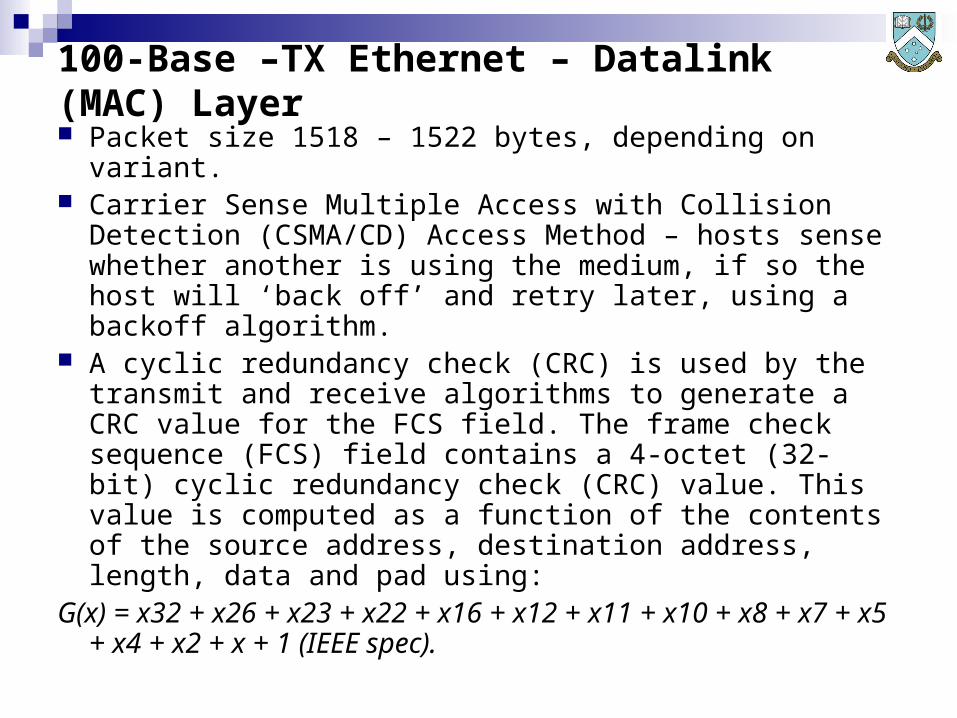
100-Base –TX Ethernet – Datalink (MAC) Layer Packet size 1518 – 1522 bytes, depending on variant. Carrier Sense Multiple Access with Collision Detection
(CSMA/CD) Access Method – hosts sense whether another is using the medium, if so the host will ‘back off’ and retry later, using a backoff algorithm.
A cyclic redundancy check (CRC) is used by the transmit and receive algorithms to generate a CRC value for the FCS field. The frame check sequence (FCS) field contains a 4-octet (32-bit) cyclic redundancy check (CRC) value. This value is computed as a function of the contents of the source address, destination address, length, data and pad using:
G(x) = x32 + x26 + x23 + x22 + x16 + x12 + x11 + x10 + x8 + x7 + x5 + x4 + x2 + x + 1 (IEEE spec).

802.3 MAC Frame Format (Packet) - IEEE

Internet Protocol / IPv4 - Network Layer Unreliable ‘best effort’ service. IP Address – 4 bytes (32 bits) 4,294,967,296 (232) unique
addresses. Example IP address 192.168.0.216. Relies on supporting protocols to associate MAC/DLL
addresses with IP addresses – ARP (RFC 826)/RARP. Relies on supporting protocols for route discovery and
maintenance – examples OSPF (Open Shortest Path First) or RIP (Routing Information Protocol).
Relies on Internet Control Message Protocol (ICMP) for error and status messaging- RFC 792 .
Refer Connected: An Internet Encyclopedia - http://www.freesoft.org/CIE/Course/Section3/7.htm or IETF RFC 791 at http://tools.ietf.org/html/rfc791 .

IPv4 Packet Structure
Refer - Connected: An Internet Encyclopedia - http://www.freesoft.org/CIE/Course/Section3/7.htm
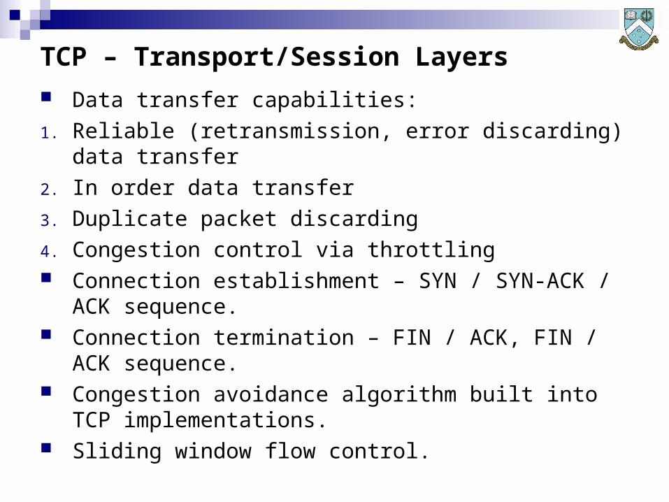
TCP – Transport/Session Layers
Data transfer capabilities:
1. Reliable (retransmission, error discarding) data transfer
2. In order data transfer
3. Duplicate packet discarding
4. Congestion control via throttling Connection establishment – SYN / SYN-ACK / ACK
sequence. Connection termination – FIN / ACK, FIN / ACK
sequence. Congestion avoidance algorithm built into TCP
implementations. Sliding window flow control.

TCP State Diagram
http://en.wikipedia.org/wiki/Image:TCP_state_diagram.png
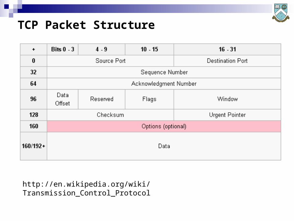
TCP Packet Structure
http://en.wikipedia.org/wiki/Transmission_Control_Protocol

Telnet – Presentation / Application Layers
RFC 854 - Telnet Protocol Specification - http://www.faqs.org/rfcs/rfc854.html
Telnet uses control codes required to manage application state.
Telnet creates a Network Virtual Terminal (NVT) which is then rendered on the user’s display.
Common implementations – Unix/Linux/BSD, Windows etc.

Systematic Design Methodology Preferred approach to designing networks. Design phases/steps:1. Identify user requirements (vs needs) and performance
demands or constraints.2. Identify available networking hardware, software and
link availability/speed between sites.3. Define/measure user load model for the network (how
many, what applications, how long etc).4. Define/measure traffic load model for the network (what
protocols for which applications and load effects).5. Define logical and physical topology for network.6. Model or simulate performance for various options in
equipment and links and cost.7. Once performance is good enough, freeze the design.
User Requirements And Performance Demands
User requirements – what functionality and what response times / QoS the user/client requests.
User needs – the actual functionality and response times the user/client needs for the system to perform well enough.
Users may often have unrealistic requirements vs actual needs, and may not have the budget to fund them.
Response times and QoS must be defined for specific applications, and specific operations/transactions in these applications.
Identify performance issues separate from the network, such as server performance, as these impact overall performance.
Available Networking Hardware, Software And Links
Networks must be built from hardware, software and must operate as required over links between sites.
A practical network can only be built using the available technology in the market.
This especially applies to the sizing of switches, hubs, routers.
Links between sites for WAN/MAN operation will have constraints in data rates, reliability, cost per usage and interfaces.
There is no point in producing a network design which cannot be built since the equipment needed does not exist.

User Load Model For The Network
We must have answers to these questions:1. How many users on the network?2. What applications are to be used by which users?3. What are the statistical properties of the user accesses
ie arrival rates?4. What are the statistical properties of the user sessions
ie service times?5. This information is used to built a load model for the
network, which shows how much activity is happening when, using which applications.
Without a load model we cannot construct a traffic model to size the network.
Measurement of similar third party or legacy sites to be upgraded may be required.

Examples of User Loads
VoIP Network – Users are Poisson distributed in arrivals and service times with some mean arrival rate and spread which changes through the day. We have some known number of users.
HTTP Server Network – External users are Poisson distributed in arrivals and accesses and we need to accommodate some fixed number.
Multimedia MPEG server - External users are Poisson distributed in arrivals and accesses and we need to accommodate some fixed number.
Database system - External users are Poisson distributed in arrivals and accesses and we need to accommodate some fixed number.
Traffic Load Model For The Network
We must have answers to these questions:1. What type of traffic (ie protocol) is associated with each
application and operation / transaction?2. What volume of traffic (packets/sec, packet size) is
associated with each application and operation / transaction?
3. What are the statistical properties of the respective traffic types, in packet sizes and arrival rates?
4. What are the performance limits for the servers used on the network?
5. If web traffic is carried, is a proxy server to be installed?6. What traffic needs to be propagated into which parts of
the network topology?7. Local vs offsite traffic demands?
Examples of Traffic Loads HTTP traffic to/from server. HTTP traffic to wider Internet, off site. VoIP traffic at a regular sample rate, using a specific
Codec type. MPEG traffic in Constant Bit Rate (CBR) or Variable Bit
Rate (VBR) formats. SSH or telnet local and remote login traffic to a server. Batch file transfers between hosts using FTP or SSH. NFS or CIFS file serving traffic between user PCs and a
main servers. All of these traffic types have characteristic behaviours,
ie symmetrical vs asymmetrical, typical packet sizes and rates, often typical statistical behaviour during sessions.
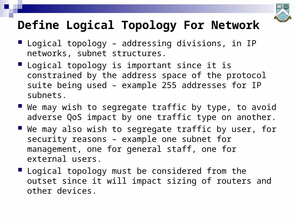
Define Logical Topology For Network
Logical topology – addressing divisions, in IP networks, subnet structures.
Logical topology is important since it is constrained by the address space of the protocol suite being used – example 255 addresses for IP subnets.
We may wish to segregate traffic by type, to avoid adverse QoS impact by one traffic type on another.
We may also wish to segregate traffic by user, for security reasons – example one subnet for management, one for general staff, one for external users.
Logical topology must be considered from the outset since it will impact sizing of routers and other devices.
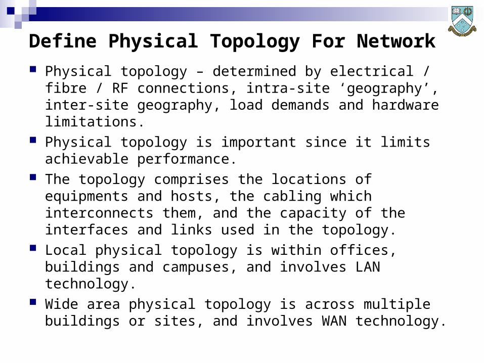
Define Physical Topology For Network
Physical topology – determined by electrical / fibre / RF connections, intra-site ‘geography’, inter-site geography, load demands and hardware limitations.
Physical topology is important since it limits achievable performance.
The topology comprises the locations of equipments and hosts, the cabling which interconnects them, and the capacity of the interfaces and links used in the topology.
Local physical topology is within offices, buildings and campuses, and involves LAN technology.
Wide area physical topology is across multiple buildings or sites, and involves WAN technology.

Defining Traffic Flows The first step in defining a topology is to understand how
much traffic will flow where within the network. A simple approach is to draw a chart in which we put all
of the systems to be connected to the network, or portion of a network, and identify which are clients and which are servers.
We then draw lines to connect clients to servers, and annotate them with traffic loads based on the load and traffic models.
This provides an indication of needed connectivity in the network, and allows sizing estimation for specific parts of the network and specific host interfaces.
We are most interested in parts of the topology where traffic is concentrated, since these experience the highest loads.

Defining Traffic Flows - Example
P rim erg y
P rim erg y
P rim erg y
Traffic Mix #2Load #2
Traffic Mix #1Load #1
Server #1Server #1Server #1
Traffic Mix
User Load Mix
Traffic Mix #3Load #3
User Population
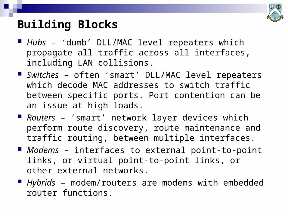
Building Blocks
Hubs – ‘dumb’ DLL/MAC level repeaters which propagate all traffic across all interfaces, including LAN collisions.
Switches – often ‘smart’ DLL/MAC level repeaters which decode MAC addresses to switch traffic between specific ports. Port contention can be an issue at high loads.
Routers – ‘smart’ network layer devices which perform route discovery, route maintenance and traffic routing, between multiple interfaces.
Modems – interfaces to external point-to-point links, or virtual point-to-point links, or other external networks.
Hybrids – modem/routers are modems with embedded router functions.

The Sizing Problem Host Interfaces, Switches and Routers are limited in
aggregate traffic capacity (Megabits/s) and packet processing rates (packets/s) refer Xterminals and Host Performance.
Modems, Hubs and LAN segments are limited in aggregate traffic capacity (Megabits/s) – refer David R. Boggs, Jeffrey C. Mogul, Christopher A. Kent, Measured Capacity of an Ethernet: Myths and Reality, DEC Research Report 88/4, September 1988 - http://research.compaq.com/wrl/techreports/abstracts/88.4.html
Once we have a traffic flow model we must reconcile the performance of the Host Interfaces, Switches, Routers Hubs and LAN segments against the traffic and performance needs.
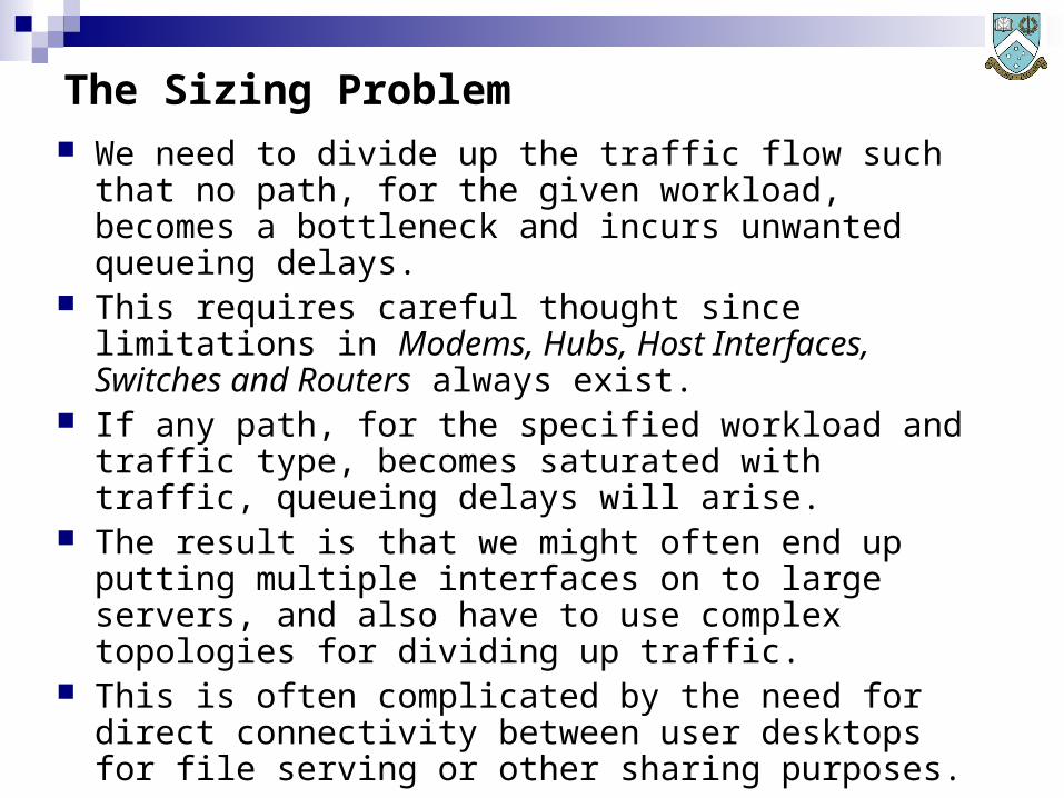
The Sizing Problem We need to divide up the traffic flow such that no path,
for the given workload, becomes a bottleneck and incurs unwanted queueing delays.
This requires careful thought since limitations in Modems, Hubs, Host Interfaces, Switches and Routers always exist.
If any path, for the specified workload and traffic type, becomes saturated with traffic, queueing delays will arise.
The result is that we might often end up putting multiple interfaces on to large servers, and also have to use complex topologies for dividing up traffic.
This is often complicated by the need for direct connectivity between user desktops for file serving or other sharing purposes.

Physical Topology
After we have sized the individual devices in the network, accounting for traffic load and connectivity, we have the basis for a physical topology design.
We produce this by inserting the networking hardware, ie routers, hubs, switches, links, into the traffic flow chart and replace notional connections with actual connections.
Having done this, we have the first pass at the network design.
We need to now verify that this topology can actually achieve its design aims.
This requires mathematical modelling or simulation effort to test its performanc against the traffic load desired.

Physical Topology - Example
P rim erg y
P rim erg y
P rim erg y
Switch #2Switch #1
Server #1Server #1
User Population
User Load Mix
Traffic Mix
Server #1
SwitchE thernet
SwitchE thernet

Safe Sizing – Peak Loads
Loads on networks inevitably varying over time. In commercial systems, peak loads arise in the late morning and mid afternoon.
Domestic web browsing peaks in mid evenings. Time zones must be accounted for, especially across
national borders. If we size a network around ‘typical’ or ‘average’ traffic
loads, what happens when a peak load arrives? At best the network underperforms, at worst services
become unusable, especially where sensitive to QoS. The basic rule to be following in sizing is that peak loads
must drive the network design, and this is critical where a performance spec is to be met, or QoS matters.
Peak Load Sizing
In practical terms, we can divide traffic into QoS sensitive traffic and QoS insensitive traffic.
Where traffic is insensitive to QoS, then a commonly used sizing strategy is to simply add up the peak capacity demands (in megabits/s) for all of the traffic and use that number to perform sizing.
Many networks are sized in this manner, and it often delivers more than adequate performance.
Where traffic is sensitive to QoS, then more precise modelling is required.
Sizing and design must then provide for bandwidth reservation, or allocation and protection of bandwidth for services sensitive to delays and packet loss.
Bandwidth Reservation
Where we must perform bandwidth reservation, we must sort traffic types into two categories – those requiring reservation, and those which do not.
We must introduce router types which can support bandwidth reservation (IntServ, DiffServ or other).
Sizing is then performed in two phases, the first being allocation of network capacity to peak loads seen with traffic needing reservation, and then allocation of capacity to traffic which does not need it.
The resulting capacity is then used to size the network. With such mixed workloads a designer must be careful in
establishing peak loads and ensuring that traffic not requiring reservation is not penalised too heavily.

Tutorial
Q&A Discussion
Related Documents


![INTEL 8086 Instruction Set RCETMicroprocessor & Microcontroller1 Suresh P. Nair [AIE, ME, (PhD)] MIEEE Professor & Head Department of Electronics and Communication.](https://static.cupdf.com/doc/110x72/56649cf95503460f949ca5c2/intel-8086-instruction-set-rcetmicroprocessor-microcontroller1-suresh-p.jpg)