ETSI TS 129 274 V12.6.0 (2014-10)
Universal Mobile Telecommunications System (UMTS); LTE;
3GPP Evolved Packet System (EPS); Evolved General Packet Radio Service (GPRS)
Tunnelling Protocol for Control plane (GTPv2-C); Stage 3
(3GPP TS 29.274 version 12.6.0 Release 12)
TECHNICAL SPECIFICATION
ETSI
ETSI TS 129 274 V12.6.0 (2014-10)13GPP TS 29.274 version 12.6.0 Release 12
Reference RTS/TSGC-0429274vc60
Keywords LTE,UMTS
ETSI
650 Route des Lucioles F-06921 Sophia Antipolis Cedex - FRANCE
Tel.: +33 4 92 94 42 00 Fax: +33 4 93 65 47 16
Siret N° 348 623 562 00017 - NAF 742 C
Association à but non lucratif enregistrée à la Sous-Préfecture de Grasse (06) N° 7803/88
Important notice
The present document can be downloaded from: http://www.etsi.org
The present document may be made available in electronic versions and/or in print. The content of any electronic and/or print versions of the present document shall not be modified without the prior written authorization of ETSI. In case of any
existing or perceived difference in contents between such versions and/or in print, the only prevailing document is the print of the Portable Document Format (PDF) version kept on a specific network drive within ETSI Secretariat.
Users of the present document should be aware that the document may be subject to revision or change of status. Information on the current status of this and other ETSI documents is available at
http://portal.etsi.org/tb/status/status.asp
If you find errors in the present document, please send your comment to one of the following services: http://portal.etsi.org/chaircor/ETSI_support.asp
Copyright Notification
No part may be reproduced or utilized in any form or by any means, electronic or mechanical, including photocopying and microfilm except as authorized by written permission of ETSI.
The content of the PDF version shall not be modified without the written authorization of ETSI. The copyright and the foregoing restriction extend to reproduction in all media.
© European Telecommunications Standards Institute 2014.
All rights reserved.
DECTTM, PLUGTESTSTM, UMTSTM and the ETSI logo are Trade Marks of ETSI registered for the benefit of its Members. 3GPPTM and LTE™ are Trade Marks of ETSI registered for the benefit of its Members and
of the 3GPP Organizational Partners. GSM® and the GSM logo are Trade Marks registered and owned by the GSM Association.
ETSI
ETSI TS 129 274 V12.6.0 (2014-10)23GPP TS 29.274 version 12.6.0 Release 12
Intellectual Property Rights IPRs essential or potentially essential to the present document may have been declared to ETSI. The information pertaining to these essential IPRs, if any, is publicly available for ETSI members and non-members, and can be found in ETSI SR 000 314: "Intellectual Property Rights (IPRs); Essential, or potentially Essential, IPRs notified to ETSI in respect of ETSI standards", which is available from the ETSI Secretariat. Latest updates are available on the ETSI Web server (http://ipr.etsi.org).
Pursuant to the ETSI IPR Policy, no investigation, including IPR searches, has been carried out by ETSI. No guarantee can be given as to the existence of other IPRs not referenced in ETSI SR 000 314 (or the updates on the ETSI Web server) which are, or may be, or may become, essential to the present document.
Foreword This Technical Specification (TS) has been produced by ETSI 3rd Generation Partnership Project (3GPP).
The present document may refer to technical specifications or reports using their 3GPP identities, UMTS identities or GSM identities. These should be interpreted as being references to the corresponding ETSI deliverables.
The cross reference between GSM, UMTS, 3GPP and ETSI identities can be found under http://webapp.etsi.org/key/queryform.asp.
Modal verbs terminology In the present document "shall", "shall not", "should", "should not", "may", "may not", "need", "need not", "will", "will not", "can" and "cannot" are to be interpreted as described in clause 3.2 of the ETSI Drafting Rules (Verbal forms for the expression of provisions).
"must" and "must not" are NOT allowed in ETSI deliverables except when used in direct citation.
ETSI
ETSI TS 129 274 V12.6.0 (2014-10)33GPP TS 29.274 version 12.6.0 Release 12
Contents
Intellectual Property Rights ................................................................................................................................ 2
Foreword ............................................................................................................................................................. 2
Modal verbs terminology .................................................................................................................................... 2
Foreword ........................................................................................................................................................... 10
1 Scope ...................................................................................................................................................... 11
2 References .............................................................................................................................................. 11
3 Definitions, symbols and abbreviations ................................................................................................. 14
3.1 Definitions ........................................................................................................................................................ 14
3.2 Symbols ............................................................................................................................................................ 14
3.3 Abbreviations ................................................................................................................................................... 14
4 General ................................................................................................................................................... 16
4.1 GTP Tunnel ...................................................................................................................................................... 16
4.2 Protocol stack ................................................................................................................................................... 16
4.2.0 General ........................................................................................................................................................ 16
4.2.1 UDP header and port numbers .................................................................................................................... 17
4.2.1.0 General .................................................................................................................................................. 17
4.2.1.1 Initial Messages ..................................................................................................................................... 18
4.2.1.2 Triggered Messages .............................................................................................................................. 18
4.2.1.3 Piggybacked Messages .......................................................................................................................... 18
4.2.2 IP header and IP addresses .......................................................................................................................... 18
4.2.2.1 Initial Messages ..................................................................................................................................... 18
4.2.2.2 Triggered Messages .............................................................................................................................. 19
4.2.2.3 Piggybacked Messages .......................................................................................................................... 19
4.2.3 Layer 2 ........................................................................................................................................................ 19
4.2.4 Layer 1 ........................................................................................................................................................ 19
4.2.5 Messages with GTPv2 defined replies: Classification of Initial and Triggered Messages ......................... 19
4.3 Transmission Order and Bit Definitions ........................................................................................................... 20
5 GTP Header for Control Plane ............................................................................................................... 20
5.1 General format .................................................................................................................................................. 20
5.2 Control Plane GTP Extension Header .............................................................................................................. 21
5.3 GTP-C header for Echo and Version Not Supported Indication messages ...................................................... 21
5.4 EPC specific GTP-C header ............................................................................................................................. 21
5.5 Usage of the GTPv2-C Header ......................................................................................................................... 22
5.5.1 General ............................................................................................................................................................. 22
5.5.2 Conditions for sending TEID=0 in GTPv2-C header ................................................................................. 23
5.6 Format of the GTPv2-C Message ..................................................................................................................... 24
6 GTP-C Message Types and Message Formats ....................................................................................... 25
6.0 General ................................................................................................................................................... 25
6.1 Message Format and Type values .................................................................................................................... 25
6.1.0 Message Type ............................................................................................................................................. 25
6.1.1 Presence requirements of Information Elements ........................................................................................ 28
6.1.2 Grouped Information Elements ................................................................................................................... 29
6.1.3 Information Element instance ..................................................................................................................... 30
6.2 Message Granularity......................................................................................................................................... 30
7 GTP-C messages .............................................................................................................................................. 31
7.1 Path Management Messages............................................................................................................................. 31
7.1.0 General ........................................................................................................................................................ 31
7.1.1 Echo Request .............................................................................................................................................. 31
7.1.2 Echo Response ............................................................................................................................................ 31
7.1.3 Version Not Supported Indication .............................................................................................................. 32
7.2 Tunnel Management Messages ........................................................................................................................ 32
ETSI
ETSI TS 129 274 V12.6.0 (2014-10)43GPP TS 29.274 version 12.6.0 Release 12
7.2.0 General ........................................................................................................................................................ 32
7.2.1 Create Session Request ............................................................................................................................... 32
7.2.2 Create Session Response ............................................................................................................................ 45
7.2.3 Create Bearer Request ................................................................................................................................ 56
7.2.4 Create Bearer Response .............................................................................................................................. 61
7.2.5 Bearer Resource Command ........................................................................................................................ 66
7.2.6 Bearer Resource Failure Indication ............................................................................................................ 69
7.2.7 Modify Bearer Request ............................................................................................................................... 71
7.2.8 Modify Bearer Response ............................................................................................................................ 85
7.2.9 Delete Session Request and Delete Bearer Request ................................................................................... 92
7.2.9.1 Delete Session Request ......................................................................................................................... 92
7.2.9.2 Delete Bearer Request ........................................................................................................................... 97
7.2.10 Delete Session Response and Delete Bearer Response ............................................................................. 101
7.2.10.1 Delete Session Response ..................................................................................................................... 101
7.2.10.2 Delete Bearer Response ...................................................................................................................... 106
7.2.11 Downlink Data Notification messages ...................................................................................................... 109
7.2.11.1 Downlink Data Notification ................................................................................................................ 109
7.2.11.2 Downlink Data Notification Acknowledge ......................................................................................... 112
7.2.11.3 Downlink Data Notification Failure Indication ................................................................................... 113
7.2.12 Delete Indirect Data Forwarding Tunnel Request .................................................................................... 114
7.2.13 Delete Indirect Data Forwarding Tunnel Response .................................................................................. 114
7.2.14 Modify Bearer Command and Failure Indication ..................................................................................... 115
7.2.14.1 Modify Bearer Command ................................................................................................................... 115
7.2.14.2 Modify Bearer Failure Indication ........................................................................................................ 117
7.2.15 Update Bearer Request ............................................................................................................................. 119
7.2.16 Update Bearer Response ........................................................................................................................... 124
7.2.17 Delete Bearer Command and Failure Indication ....................................................................................... 128
7.2.17.1 Delete Bearer Command ..................................................................................................................... 128
7.2.17.2 Delete Bearer Failure Indication ......................................................................................................... 130
7.2.18 Create Indirect Data Forwarding Tunnel Request .................................................................................... 132
7.2.19 Create Indirect Data Forwarding Tunnel Response .................................................................................. 135
7.2.20 Void .......................................................................................................................................................... 136
7.2.21 Release Access Bearers Request ............................................................................................................... 136
7.2.22 Release Access Bearers Response ............................................................................................................ 137
7.2.23 Stop Paging Indication .............................................................................................................................. 139
7.2.24 Modify Access Bearers Request ............................................................................................................... 139
7.2.25 Modify Access Bearers Response ............................................................................................................. 141
7.3 Mobility Management Messages .................................................................................................................... 144
7.3.1 Forward Relocation Request ..................................................................................................................... 144
7.3.2 Forward Relocation Response .................................................................................................................. 152
7.3.3 Forward Relocation Complete Notification .............................................................................................. 155
7.3.4 Forward Relocation Complete Acknowledge ........................................................................................... 155
7.3.5 Context Request ........................................................................................................................................ 156
7.3.6 Context Response ..................................................................................................................................... 158
7.3.7 Context Acknowledge............................................................................................................................... 165
7.3.8 Identification Request ............................................................................................................................... 166
7.3.9 Identification Response ............................................................................................................................. 167
7.3.10 Forward Access Context Notification ....................................................................................................... 168
7.3.11 Forward Access Context Acknowledge .................................................................................................... 168
7.3.12 Detach Notification ................................................................................................................................... 169
7.3.13 Detach Acknowledge ................................................................................................................................ 170
7.3.14 Change Notification Request .................................................................................................................... 170
7.3.15 Change Notification Response .................................................................................................................. 172
7.3.16 Relocation Cancel Request ....................................................................................................................... 173
7.3.17 Relocation Cancel Response ..................................................................................................................... 174
7.3.18 Configuration Transfer Tunnel ................................................................................................................. 174
7.3.19 RAN Information Relay ............................................................................................................................ 174
7.3.20 ISR Status Indication ................................................................................................................................ 175
7.4 CS Fallback and SRVCC related messages .................................................................................................... 175
7.4.1 Suspend Notification................................................................................................................................. 175
7.4.2 Suspend Acknowledge .............................................................................................................................. 177
7.4.3 Resume Notification ................................................................................................................................. 177
ETSI
ETSI TS 129 274 V12.6.0 (2014-10)53GPP TS 29.274 version 12.6.0 Release 12
7.4.4 Resume Acknowledge .............................................................................................................................. 178
7.4.5 CS Paging Indication ................................................................................................................................ 178
7.4.6 Alert MME Notification ........................................................................................................................... 179
7.4.7 Alert MME Acknowledge ........................................................................................................................ 179
7.4.8 UE Activity Notification ........................................................................................................................... 179
7.4.9 UE Activity Acknowledge ........................................................................................................................ 180
7.5 Non-3GPP access related messages ............................................................................................................... 180
7.5.1 Create Forwarding Tunnel Request .......................................................................................................... 180
7.5.2 Create Forwarding Tunnel Response ........................................................................................................ 180
7.6 Reliable Delivery of Signalling Messages ...................................................................................................... 181
7.7 Error Handling ................................................................................................................................................ 182
7.7.0 Handling Piggybacked Messages ............................................................................................................. 182
7.7.1 Protocol Errors .......................................................................................................................................... 182
7.7.2 Different GTP Versions ............................................................................................................................ 183
7.7.3 GTP Message of Invalid Length ............................................................................................................... 183
7.7.4 Unknown GTP Message ........................................................................................................................... 183
7.7.5 Unexpected GTP Message ........................................................................................................................ 183
7.7.6 Missing Information Elements .................................................................................................................. 183
7.7.7 Invalid Length Information Element ........................................................................................................ 184
7.7.8 Semantically incorrect Information Element ............................................................................................ 185
7.7.9 Unknown or unexpected Information Element ......................................................................................... 185
7.7.10 Repeated Information Elements ................................................................................................................ 185
7.7.11 TFT Error Handling .................................................................................................................................. 185
7.8 Path Failure .................................................................................................................................................... 186
7.9 Restoration and Recovery .............................................................................................................................. 186
7.9.0 General ...................................................................................................................................................... 186
7.9.1 Delete PDN Connection Set Request ........................................................................................................ 186
7.9.2 Delete PDN Connection Set Response ..................................................................................................... 186
7.9.3 Update PDN Connection Set Request ....................................................................................................... 187
7.9.4 Update PDN Connection Set Response .................................................................................................... 187
7.9.5 PGW Restart Notification ......................................................................................................................... 188
7.9.6 PGW Restart Notification Acknowledge .................................................................................................. 188
7.9.7 PGW Downlink Triggering Notification .................................................................................................. 188
7.9.8 PGW Downlink Triggering Acknowledge ............................................................................................... 189
7.10 Fallback to GTPv1 mechanism ...................................................................................................................... 189
7.11 Fallback to GTPv0.......................................................................................................................................... 190
7.12 Trace Management Messages ......................................................................................................................... 190
7.12.1 Trace Session Activation .......................................................................................................................... 190
7.12.2 Trace Session Deactivation ....................................................................................................................... 191
7.13 MBMS Messages ........................................................................................................................................... 191
7.13.1 MBMS Session Start Request ................................................................................................................... 191
7.13.2 MBMS Session Start Response ................................................................................................................ 192
7.13.3 MBMS Session Update Request ............................................................................................................... 193
7.13.4 MBMS Session Update Response ............................................................................................................ 193
7.13.5 MBMS Session Stop Request ................................................................................................................... 194
7.13.6 MBMS Session Stop Response ................................................................................................................. 194
8 GTP-C Information Elements .............................................................................................................. 195
8.1 Information Element Types ............................................................................................................................ 195
8.2 Information Element Format .......................................................................................................................... 198
8.2.1 General ...................................................................................................................................................... 198
8.2.2 Handling ASN.1/PER encoded parameters .............................................................................................. 198
8.3 International Mobile Subscriber Identity (IMSI) ............................................................................................ 198
8.4 Cause .............................................................................................................................................................. 199
8.5 Recovery (Restart Counter) ............................................................................................................................ 204
8.6 Access Point Name (APN) ............................................................................................................................. 205
8.7 Aggregate Maximum Bit Rate (AMBR) ........................................................................................................ 205
8.8 EPS Bearer ID (EBI) ...................................................................................................................................... 205
8.9 IP Address ...................................................................................................................................................... 206
8.10 Mobile Equipment Identity (MEI) .................................................................................................................. 206
8.11 MSISDN ......................................................................................................................................................... 206
8.12 Indication ........................................................................................................................................................ 206
ETSI
ETSI TS 129 274 V12.6.0 (2014-10)63GPP TS 29.274 version 12.6.0 Release 12
8.13 Protocol Configuration Options (PCO) .......................................................................................................... 209
8.14 PDN Address Allocation (PAA) .................................................................................................................... 210
8.15 Bearer Quality of Service (Bearer QoS) ......................................................................................................... 210
8.16 Flow Quality of Service (Flow QoS) .............................................................................................................. 211
8.17 RAT Type ....................................................................................................................................................... 212
8.18 Serving Network ............................................................................................................................................ 212
8.19 EPS Bearer Level Traffic Flow Template (Bearer TFT) ................................................................................ 213
8.20 Traffic Aggregate Description (TAD) ............................................................................................................ 213
8.21 User Location Information (ULI) ................................................................................................................... 213
8.21.1 CGI field ................................................................................................................................................... 214
8.21.2 SAI field ................................................................................................................................................... 214
8.21.3 RAI field ................................................................................................................................................... 214
8.21.4 TAI field ................................................................................................................................................... 215
8.21.5 ECGI field ................................................................................................................................................. 215
8.21.6 LAI field ................................................................................................................................................... 215
8.22 Fully Qualified TEID (F-TEID) ..................................................................................................................... 216
8.23 TMSI .............................................................................................................................................................. 218
8.24 Global CN-Id .................................................................................................................................................. 218
8.25 S103 PDN Data Forwarding Info (S103PDF) ................................................................................................ 218
8.26 S1-U Data Forwarding (S1UDF) .................................................................................................................... 219
8.27 Delay Value .................................................................................................................................................... 219
8.28 Bearer Context ................................................................................................................................................ 219
8.29 Charging ID .................................................................................................................................................... 220
8.30 Charging Characteristics ................................................................................................................................ 220
8.31 Trace Information ........................................................................................................................................... 220
8.32 Bearer Flags .................................................................................................................................................... 221
8.33 Void ................................................................................................................................................................ 221
8.34 PDN Type ....................................................................................................................................................... 221
8.35 Procedure Transaction ID (PTI) ..................................................................................................................... 222
8.36 Void ................................................................................................................................................................ 222
8.37 Void ................................................................................................................................................................ 222
8.38 MM Context ................................................................................................................................................... 222
8.39 PDN Connection ............................................................................................................................................ 230
8.40 PDU Numbers ................................................................................................................................................ 230
8.41 Packet TMSI (P-TMSI) .................................................................................................................................. 230
8.42 P-TMSI Signature........................................................................................................................................... 231
8.43 Hop Counter ................................................................................................................................................... 231
8.44 UE Time Zone ................................................................................................................................................ 231
8.45 Trace Reference .............................................................................................................................................. 232
8.46 Complete Request Message ............................................................................................................................ 232
8.47 GUTI .............................................................................................................................................................. 232
8.48 Fully Qualified Container (F-Container) ........................................................................................................ 233
8.49 Fully Qualified Cause (F-Cause) .................................................................................................................... 234
8.50 PLMN ID........................................................................................................................................................ 235
8.51 Target Identification ....................................................................................................................................... 235
8.52 Void ................................................................................................................................................................ 237
8.53 Packet Flow ID ............................................................................................................................................... 237
8.54 RAB Context .................................................................................................................................................. 238
8.55 Source RNC PDCP context info ..................................................................................................................... 238
8.56 Port Number ................................................................................................................................................... 238
8.57 APN Restriction ............................................................................................................................................. 239
8.58 Selection Mode ............................................................................................................................................... 239
8.59 Source Identification ...................................................................................................................................... 240
8.60 Void ................................................................................................................................................................ 240
8.61 Change Reporting Action ............................................................................................................................... 240
8.62 Fully qualified PDN Connection Set Identifier (FQ-CSID) ........................................................................... 241
8.63 Channel needed .............................................................................................................................................. 242
8.64 eMLPP Priority .............................................................................................................................................. 242
8.65 Node Type ...................................................................................................................................................... 242
8.66 Fully Qualified Domain Name (FQDN) ......................................................................................................... 243
8.67 Private Extension ............................................................................................................................................ 243
8.68 Transaction Identifier (TI) .............................................................................................................................. 243
ETSI
ETSI TS 129 274 V12.6.0 (2014-10)73GPP TS 29.274 version 12.6.0 Release 12
8.69 MBMS Session Duration ................................................................................................................................ 244
8.70 MBMS Service Area ...................................................................................................................................... 244
8.71 MBMS Session Identifier ............................................................................................................................... 244
8.72 MBMS Flow Identifier ................................................................................................................................... 245
8.73 MBMS IP Multicast Distribution ................................................................................................................... 245
8.74 MBMS Distribution Acknowledge ................................................................................................................. 246
8.75 User CSG Information (UCI) ......................................................................................................................... 246
8.76 CSG Information Reporting Action ............................................................................................................... 247
8.77 RFSP Index .................................................................................................................................................... 247
8.78 CSG ID ........................................................................................................................................................... 248
8.79 CSG Membership Indication (CMI) ............................................................................................................... 248
8.80 Service indicator ............................................................................................................................................. 248
8.81 Detach Type ................................................................................................................................................... 249
8.82 Local Distinguished Name (LDN) ................................................................................................................. 249
8.83 Node Features ................................................................................................................................................. 249
8.84 MBMS Time to Data Transfer ....................................................................................................................... 250
8.85 Throttling ........................................................................................................................................................ 250
8.86 Allocation/Retention Priority (ARP) .............................................................................................................. 251
8.87 EPC Timer ...................................................................................................................................................... 252
8.88 Signalling Priority Indication ......................................................................................................................... 252
8.89 Temporary Mobile Group Identity (TMGI) ................................................................................................... 253
8.90 Additional MM context for SRVCC .............................................................................................................. 253
8.91 Additional flags for SRVCC .......................................................................................................................... 253
8.92 Void ................................................................................................................................................................ 254
8.93 MDT Configuration ........................................................................................................................................ 254
8.94 Additional Protocol Configuration Options (APCO) ..................................................................................... 255
8.95 Absolute Time of MBMS Data Transfer ........................................................................................................ 255
8.96 H(e)NB Information Reporting ...................................................................................................................... 255
8.97 IPv4 Configuration Parameters (IP4CP) ........................................................................................................ 256
8.98 Change to Report Flags .................................................................................................................................. 256
8.99 Action Indication ............................................................................................................................................ 256
8.100 TWAN Identifier ...................................................................................................................................... 257
8.101 ULI Timestamp ......................................................................................................................................... 258
8.102 MBMS Flags .................................................................................................................................................. 259
8.103 RAN/NAS Cause ............................................................................................................................................ 259
8.104 CN Operator Selection Entity ......................................................................................................................... 260
8.105 Trusted WLAN Mode Indication ................................................................................................................... 260
8.106 Node Number ................................................................................................................................................. 261
8.107 Node Identifier ............................................................................................................................................... 261
8.108 Presence Reporting Area Action .................................................................................................................... 262
8.109 Presence Reporting Area Information ............................................................................................................ 263
8.110 TWAN Identifier Timestamp ......................................................................................................................... 263
8.111 Overload Control Information ........................................................................................................................ 264
8.112 Load Control Information .............................................................................................................................. 264
8.113 Metric ........................................................................................................................................................ 264
8.114 Sequence Number ..................................................................................................................................... 265
8.115 APN and Relative Capacity ...................................................................................................................... 265
9 Security................................................................................................................................................. 265
10 IP - The Networking Technology used by GTP ................................................................................... 266
10.1 IP Version ....................................................................................................................................................... 266
10.2 IP Fragmentation ............................................................................................................................................ 266
11 Notification of supported features between peer GTP-C entities ......................................................... 266
11.1 General ........................................................................................................................................................... 266
11.1.1 Introduction............................................................................................................................................... 266
11.1.2 Defining a feature ..................................................................................................................................... 266
11.2 Dynamic discovery of supported features ...................................................................................................... 267
11.2.1 General ...................................................................................................................................................... 267
11.2.2 Features supported by direct peer GTP-C entities .................................................................................... 267
12 GTP-C load & overload control mechanism ........................................................................................ 267
ETSI
ETSI TS 129 274 V12.6.0 (2014-10)83GPP TS 29.274 version 12.6.0 Release 12
12.1 General ........................................................................................................................................................... 267
12.1.1 GTP-C overload problem .......................................................................................................................... 267
12.1.2 Scenarios leading to overload ................................................................................................................... 268
12.1.3 Load & overload control concepts ............................................................................................................ 268
12.2 Load control solution...................................................................................................................................... 269
12.2.1 Principles of load control .......................................................................................................................... 269
12.2.2 Applicability to 3GPP and non-3GPP access based interfaces ................................................................. 269
12.2.3 Node level load control ............................................................................................................................. 270
12.2.4 APN level load control ............................................................................................................................. 270
12.2.4.1 General ................................................................................................................................................ 270
12.2.4.2 Justifications for APN load control support ........................................................................................ 270
12.2.4.3 Elements of APN load control ............................................................................................................ 271
12.2.5 Load Control Information ......................................................................................................................... 271
12.2.5.1 Definition ............................................................................................................................................ 271
12.2.5.1.1 General description ........................................................................................................................ 271
12.2.5.1.2 Parameters ..................................................................................................................................... 272
12.2.5.1.2.1 Load Control Sequence Number .............................................................................................. 272
12.2.5.1.2.2 Load Metric.............................................................................................................................. 273
12.2.5.1.2.3 List-of-APN_and_Relative Capacity ....................................................................................... 273
12.2.5.1.3 Handling of parameters ................................................................................................................. 274
12.2.5.2 Frequency of inclusion ........................................................................................................................ 274
12.2.5.3 Limit on maximum number of instances ............................................................................................. 275
12.2.6 Discovery of the support of the feature by the peer node ......................................................................... 275
12.2.7 Issues in the network with partial support of the feature .......................................................................... 275
12.3 Overload control solution ............................................................................................................................... 275
12.3.1 Principles of overload control ................................................................................................................... 275
12.3.2 Applicability to 3GPP and non-3GPP access based interfaces ................................................................. 276
12.3.3 Node level overload control ...................................................................................................................... 277
12.3.4 APN level overload control ...................................................................................................................... 277
12.3.4.1 General ................................................................................................................................................ 277
12.3.4.2 Elements of APN overload control ..................................................................................................... 277
12.3.5 Overload Control Information .................................................................................................................. 277
12.3.5.1 Definition ............................................................................................................................................ 277
12.3.5.1.1 General description ........................................................................................................................ 277
12.3.5.1.2 Parameters ..................................................................................................................................... 278
12.3.5.1.2.1 Overload Control Sequence Number ....................................................................................... 278
12.3.5.1.2.2 Period of Validity ..................................................................................................................... 279
12.3.5.1.2.3 Overload Reduction Metric ...................................................................................................... 279
12.3.5.1.2.4 List of APNs ............................................................................................................................ 280
12.3.5.1.3 Handling of parameters ................................................................................................................. 280
12.3.5.2 Frequency of inclusion ........................................................................................................................ 281
12.3.5.3 Limit on maximum number of instances ............................................................................................. 281
12.3.6 Propagating the MME/S4-SGSN identity to the PGW ............................................................................. 281
12.3.7 Updating the PGW with overload control information of the target MME/S4-SGSN ............................. 282
12.3.8 The interaction with APN congestion control using the PGW Back-Off Time ........................................ 282
12.3.9 Message throttling .................................................................................................................................... 283
12.3.9.1 General ................................................................................................................................................ 283
12.3.9.2 Throttling algorithm – "Loss" ............................................................................................................. 283
12.3.9.2.1 Description .................................................................................................................................... 283
12.3.9.3 Message prioritization ......................................................................................................................... 283
12.3.9.3.1 Description .................................................................................................................................... 283
12.3.9.3.2 Based on procedures ...................................................................................................................... 284
12.3.9.3.3 Based on session parameters ......................................................................................................... 285
12.3.10 Enforcement of overload control .............................................................................................................. 285
12.3.10.1 General ................................................................................................................................................ 285
12.3.10.2 Aspects related to enforcement of the overload control ...................................................................... 286
12.3.10.2.1 Good throughput of the network.................................................................................................... 286
12.3.10.2.2 Message processing efficiency at the source GTP-C entity ........................................................... 286
12.3.10.2.3 Self-protection by the overloaded GTP-C entity ........................................................................... 286
12.3.10.3 Enforcement of overload control between GTP-C entities in direct contact ....................................... 286
12.3.10.4 Enforcement of overload control between remote GTP-C entities ..................................................... 286
12.3.10.4.1 Description .................................................................................................................................... 286
ETSI
ETSI TS 129 274 V12.6.0 (2014-10)93GPP TS 29.274 version 12.6.0 Release 12
12.3.11 Discovery of the support of the feature by the peer node ......................................................................... 287
12.3.12 Issues in the network with partial support of the feature .......................................................................... 287
12.3.13 Implicit overload control mechanisms ...................................................................................................... 287
Annex A (Informative): Backward Compatibility Guidelines for Information Elements ............. 288
Annex B (Informative): Transparent copying of RANAP/S1AP IEs into GTP IEs ....................... 289
B.1 General ........................................................................................................................................................... 289
B.2 Handover/Relocation related generic transparent Containers over RANAP, S1-AP and GTP ...................... 289
B.3 Other RANAP and S1-AP IEs ........................................................................................................................ 291
Annex C (Normative): MME/S4-SGSN mapping table between S11/S4 and NAS Cause values ............................................................................................................. 292
Annex D (Informative): GTP-C load and overload control mechanism .......................................... 296
D.1 GTP-C interfaces not supporting Load Control.............................................................................................. 296
D.2 GTP-C interfaces not supporting Overload Control ....................................................................................... 296
D.3 "Loss" throttling algorithm ............................................................................................................................. 297
D.3.1 Example of possible implementation ............................................................................................................. 297
D.4 Enforcement of overload control between remote GTP-C entities ................................................................. 297
D.4.1 Example of possible implementation ............................................................................................................. 297
Annex E (Informative): Change History ............................................................................................ 299
History ............................................................................................................................................................ 315
ETSI
ETSI TS 129 274 V12.6.0 (2014-10)103GPP TS 29.274 version 12.6.0 Release 12
Foreword This Technical Specification has been produced by the 3rd Generation Partnership Project (3GPP).
The contents of the present document are subject to continuing work within the TSG and may change following formal TSG approval. Should the TSG modify the contents of the present document, it will be re-released by the TSG with an identifying change of release date and an increase in version number as follows:
Version x.y.z
where:
x the first digit:
1 presented to TSG for information;
2 presented to TSG for approval;
3 or greater indicates TSG approved document under change control.
y the second digit is incremented for all changes of substance, i.e. technical enhancements, corrections, updates, etc.
z the third digit is incremented when editorial only changes have been incorporated in the document.
ETSI
ETSI TS 129 274 V12.6.0 (2014-10)113GPP TS 29.274 version 12.6.0 Release 12
1 Scope The present document specifies the stage 3 of the control plane of the GPRS Tunnelling Protocol, Version 2 for Evolved Packet System interfaces (GTPv2-C).
In this document, unless otherwise specified, the S2a, S2b, S5 and S8 interfaces refer always to the GTP-based S2a, S2b, S5 and S8 interfaces respectively .
GTPv2-C shall be used across the following EPC signalling interfaces: S2a, S2b, S3, S4, S5, S8, S10, S11 and S16.
GTPv2-C shall be used across the Sm and Sn interfaces for MBMS in EPS.
GTPv2-C based protocols shall also be used across Sv (3GPP TS 29.280 [15]) and S101/S121 (3GPP TS 29.276 [14]) interfaces.
The procedures supported between the TWAN and the PGW on the S2a interface, and between the ePDG and the PGW on the S2b interface are specified in 3GPP TS 23.402 [45].
The present document specifies functions, procedures and information which apply to GERAN Iu mode. However, functionality related to GERAN Iu mode is neither maintained nor enhanced.
2 References The following documents contain provisions which, through reference in this text, constitute provisions of the present document.
• References are either specific (identified by date of publication, edition number, version number, etc.) or non-specific.
• For a specific reference, subsequent revisions do not apply.
• For a non-specific reference, the latest version applies. In the case of a reference to a 3GPP document (including a GSM document), a non-specific reference implicitly refers to the latest version of that document in the same Release as the present document.
[1] 3GPP TR 21.905: "Vocabulary for 3GPP Specifications".
[2] 3GPP TS 23.003: "Numbering, addressing and identification".
[3] 3GPP TS 23.401: "General Packet Radio Service (GPRS) enhancements for Evolved Universal Terrestrial Radio Access Network (E-UTRAN) access".
[4] 3GPP TS 29.060: "General Packet Radio Service (GPRS); GPRS Tunnelling Protocol (GTP) across the Gn and Gp interface".
[5] 3GPP TS 24.008: "Mobile radio interface Layer 3 specification; Core network protocols; Stage 3".
[6] IETF RFC 791 (STD 0005): "Internet Protocol", J. Postel.
[7] IETF RFC 768 (STD 0006): "User Datagram Protocol", J. Postel.
[8] 3GPP TS 32.251: "Telecommunication Management; Charging Management; Packet Switched (PS) domain charging.
[9] 3GPP TS 32.298: "Telecommunication Management; Charging Management; Charging Data Record (CDR) parameter classification.
[10] 3GPP TS 36.413: "Evolved Universal Terrestrial Radio Access Network (E-UTRAN); S1 Application Protocol (S1AP)".
[11] 3GPP TS 33.102: "3G security; Security architecture".
ETSI
ETSI TS 129 274 V12.6.0 (2014-10)123GPP TS 29.274 version 12.6.0 Release 12
[12] 3GPP TS 33.401: "3GPP System Architecture Evolution (SAE); Security architecture".
[13] 3GPP TS 29.281: "General Packet Radio System (GPRS) Tunnelling Protocol User Plane (GTPv1-U)".
[14] 3GPP TS 29.276: "3GPP Evolved Packet System (EPS); Optimized handover procedures and protocols between E-UTRAN Access and cdma2000 HRPD Access; Stage 3".
[15] 3GPP TS 29.280: "Evolved Packet System (EPS); 3GPP Sv interface (MME to MSC, and SGSN to MSC) for SRVCC".
[16] IETF RFC 2460: "Internet Protocol, Version 6 (IPv6) Specification".
[17] 3GPP TS 23.007: "Restoration procedures".
[18] 3GPP TS 32.422: "Telecommunication management; Subscriber and equipment trace; Trace control and configuration management ".
[19] 3GPP TS 36.300: "Evolved Universal Terrestrial Radio Access (E-UTRA) and Evolved Universal Terrestrial Radio Access Network (E-UTRAN); Overall description; Stage 2".
[20] 3GPP TS 36.414: "Evolved Universal Terrestrial Radio Access Network (E-UTRAN); S1 data transport".
[21] 3GPP TS 23.272: "Circuit Switched (CS) fallback in Evolved Packet System (EPS); Stage 2".
[22] 3GPP TS 29.118: "Mobility Management Entity (MME) - Visitor Location Register (VLR) SGs interface specification".
[23] 3GPP TS 24.301: "Non-Access-Stratum (NAS) protocol for Evolved Packet System (EPS); Stage 3".
[24] void
[25] ITU-T Recommendation E.164: "The international public telecommunication numbering plan".
[26] 3GPP TS 29.275: "Proxy Mobile IPv6 (PMIPv6) based Mobility and Tunnelling protocols; Stage 3".
[27] 3GPP TS 44.018: "Mobile radio interface layer 3 specification; Radio Resource Control Protocol".
[28] 3GPP TS 48.008: "Mobile Switching Centre - Base Station System (MSC-BSS) interface; Layer 3 specification".
[29] 3GPP TS 29.212: "Policy and Charging Control (PCC); Reference points".
[30] 3GPP TS 24.007: "Mobile radio interface signalling layer 3; General Aspects".
[31] IETF RFC 1035: "Domain Names - Implementation and Specification".
[32] 3GPP TS 29.303: "Domain Name System Procedures; Stage 3".
[33] 3GPP TS 25.413: "UTRAN Iu interface Radio Access Network Application Part (RANAP) signalling".
[34] 3GPP TS 48.018: "General Packet Radio Service (GPRS); Base Station System (BSS) - Serving GPRS Support Node (SGSN); BSS GPRS protocol (BSSGP)".
[35] 3GPP TS 23.060: "General Packet Radio Service (GPRS); Service description; Stage 2".
ETSI
ETSI TS 129 274 V12.6.0 (2014-10)133GPP TS 29.274 version 12.6.0 Release 12
[36] 3GPP TS 32.295: "Telecommunication management; Charging management; Charging Data Record (CDR) transfer".
[37] 3GPP TS 23.246: "Multimedia Broadcast/Multicast Service (MBMS); Architecture and functional description".
[38] 3GPP TS 29.061: "Interworking between the Public Land Mobile Network (PLMN) supporting packet based services and Packet Data Networks (PDN) ".
[39] IETF RFC 3588: "Diameter Base Protocol ".
[40] IETF RFC 4607: "Source-Specific Multicast for IP".
[41] 3GPP TS 29.002: "Mobile Application Part (MAP) specification".
[42] 3GPP TS 29.010: "Information element mapping between Mobile Station - Base Station System (MS - BSS) and Base Station System - Mobile-services Switching Centre (BSS - MSC); Signalling procedures and the Mobile Application Part (MAP)".
[43] 3GPP TS 23.216: "Single Radio Voice Call Continuity (SRVCC); Stage 2".
[44] 3GPP TS 32.423: "Telecommunication management; Subscriber and equipment trace: Trace data definition and management".
[45] 3GPP TS 23.402: "Architecture enhancements for non-3GPP accesses.
[46] 3GPP TR 25.999: "HSPA Evolution (FDD)".
[47] 3GPP TS 23.292: "IP Multimedia Subsystem (IMS) centralized services".
[48] 3GPP TS 23.203: "Policy and charging control architecture; Stage 2".
[49] ITU-T Recommendation X.691 (07/2002): "Information technology – ASN.1 encoding rules: Specification of Packed Encoding Rules (PER)".
[50] 3GPP TS 33.402: "3GPP System Architecture Evolution (SAE); Security aspects of non-3GPP accesses".
[51] 3GPP TS 23.139: "3GPP system - fixed broadband access network interworking; Stage 2".
[52] IEEE Std 802.11-2012: "IEEE Standard for Information technology - Telecommunications and information exchange between systems - Local and metropolitan area networks - Specific requirements - Part 11: Wireless LAN Medium Access Control (MAC) and Physical Layer (PHY) Specifications".
[53] IETF RFC 5905: "Network Time Protocol Version 4: Protocol and Algorithms Specification".
[54] 3GPP TS 32.299: "Telecommunication Management; Charging Management; Diameter charging applications.
[55] 3GPP TS 23.251: " Network Sharing; Architecture and Functional Description".
[56] 3GPP TS 23.271: "Location Services".
[57] 3GPP TS 29.173: "Diameter-based SLh interface for Control Plane LCS".
[58] IETF RFC 5453: "Reserved IPv6 Interface Identifiers".
[59] IETF RFC 4776: "Dynamic Host Configuration Protocol (DHCPv4 and DHCPv6) Option for Civic Addresses Configuration Information".
[60] IETF RFC 3046: "DHCP Relay Agent Information Option".
[61] 3GPP TS 23.380: "IMS Restoration Procedures".
ETSI
ETSI TS 129 274 V12.6.0 (2014-10)143GPP TS 29.274 version 12.6.0 Release 12
3 Definitions, symbols and abbreviations
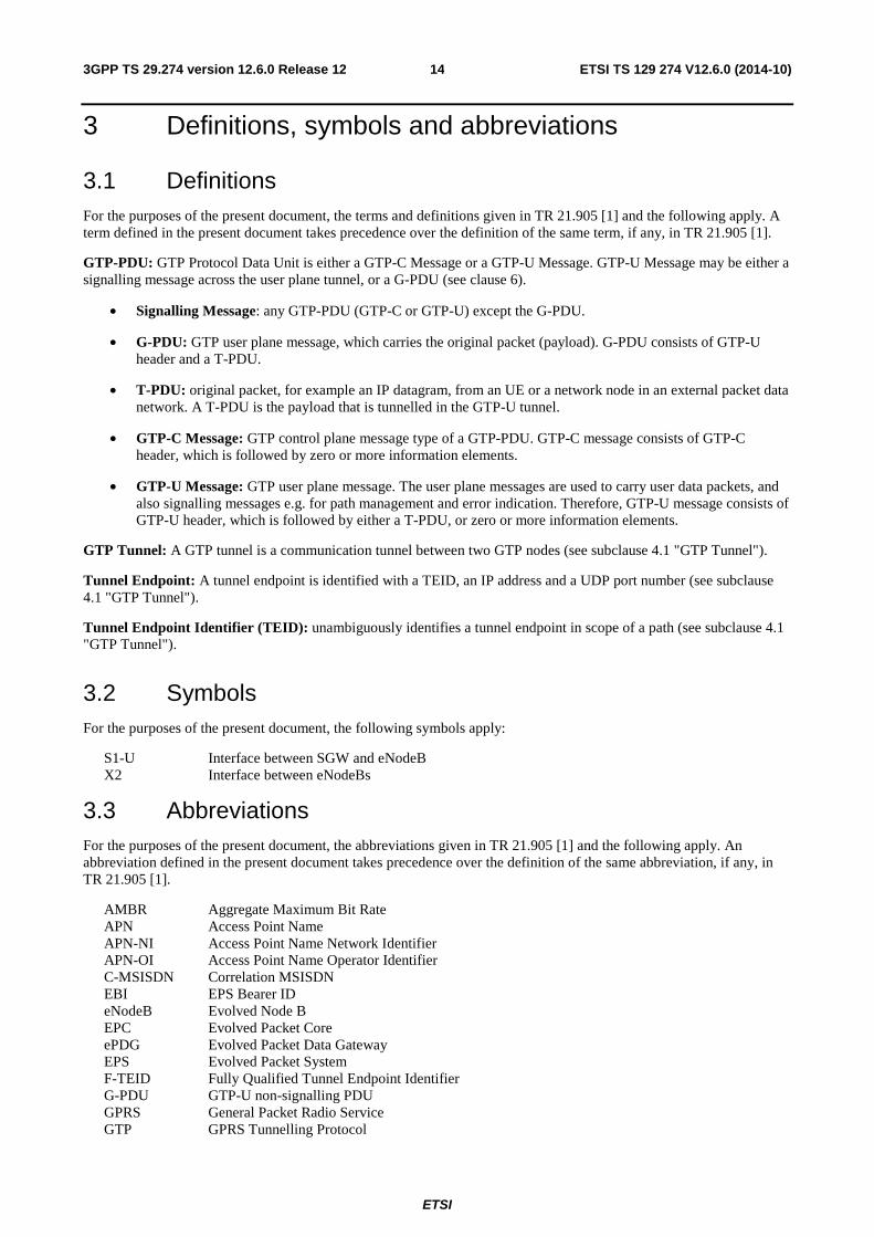
3.1 Definitions For the purposes of the present document, the terms and definitions given in TR 21.905 [1] and the following apply. A term defined in the present document takes precedence over the definition of the same term, if any, in TR 21.905 [1].
GTP-PDU: GTP Protocol Data Unit is either a GTP-C Message or a GTP-U Message. GTP-U Message may be either a signalling message across the user plane tunnel, or a G-PDU (see clause 6).
• Signalling Message: any GTP-PDU (GTP-C or GTP-U) except the G-PDU.
• G-PDU: GTP user plane message, which carries the original packet (payload). G-PDU consists of GTP-U header and a T-PDU.
• T-PDU: original packet, for example an IP datagram, from an UE or a network node in an external packet data network. A T-PDU is the payload that is tunnelled in the GTP-U tunnel.
• GTP-C Message: GTP control plane message type of a GTP-PDU. GTP-C message consists of GTP-C header, which is followed by zero or more information elements.
• GTP-U Message: GTP user plane message. The user plane messages are used to carry user data packets, and also signalling messages e.g. for path management and error indication. Therefore, GTP-U message consists of GTP-U header, which is followed by either a T-PDU, or zero or more information elements.
GTP Tunnel: A GTP tunnel is a communication tunnel between two GTP nodes (see subclause 4.1 "GTP Tunnel").
Tunnel Endpoint: A tunnel endpoint is identified with a TEID, an IP address and a UDP port number (see subclause 4.1 "GTP Tunnel").
Tunnel Endpoint Identifier (TEID): unambiguously identifies a tunnel endpoint in scope of a path (see subclause 4.1 "GTP Tunnel").
3.2 Symbols For the purposes of the present document, the following symbols apply:
S1-U Interface between SGW and eNodeB X2 Interface between eNodeBs
3.3 Abbreviations For the purposes of the present document, the abbreviations given in TR 21.905 [1] and the following apply. An abbreviation defined in the present document takes precedence over the definition of the same abbreviation, if any, in TR 21.905 [1].
AMBR Aggregate Maximum Bit Rate APN Access Point Name APN-NI Access Point Name Network Identifier APN-OI Access Point Name Operator Identifier C-MSISDN Correlation MSISDN EBI EPS Bearer ID eNodeB Evolved Node B EPC Evolved Packet Core ePDG Evolved Packet Data Gateway EPS Evolved Packet System F-TEID Fully Qualified Tunnel Endpoint Identifier G-PDU GTP-U non-signalling PDU GPRS General Packet Radio Service GTP GPRS Tunnelling Protocol
ETSI
ETSI TS 129 274 V12.6.0 (2014-10)153GPP TS 29.274 version 12.6.0 Release 12
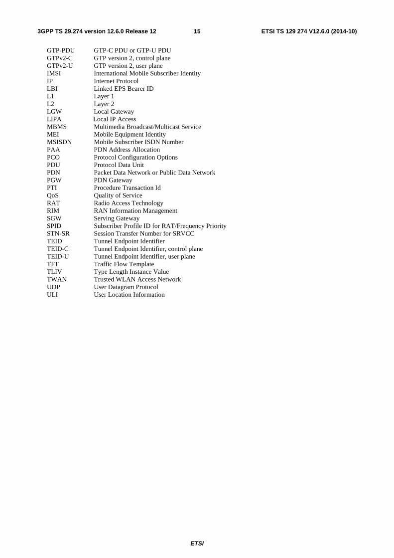
GTP-PDU GTP-C PDU or GTP-U PDU GTPv2-C GTP version 2, control plane GTPv2-U GTP version 2, user plane IMSI International Mobile Subscriber Identity IP Internet Protocol LBI Linked EPS Bearer ID L1 Layer 1 L2 Layer 2 LGW Local Gateway LIPA Local IP Access MBMS Multimedia Broadcast/Multicast Service MEI Mobile Equipment Identity MSISDN Mobile Subscriber ISDN Number PAA PDN Address Allocation PCO Protocol Configuration Options PDU Protocol Data Unit PDN Packet Data Network or Public Data Network PGW PDN Gateway PTI Procedure Transaction Id QoS Quality of Service RAT Radio Access Technology RIM RAN Information Management SGW Serving Gateway SPID Subscriber Profile ID for RAT/Frequency Priority STN-SR Session Transfer Number for SRVCC TEID Tunnel Endpoint Identifier TEID-C Tunnel Endpoint Identifier, control plane TEID-U Tunnel Endpoint Identifier, user plane TFT Traffic Flow Template TLIV Type Length Instance Value TWAN Trusted WLAN Access Network UDP User Datagram Protocol ULI User Location Information
ETSI
ETSI TS 129 274 V12.6.0 (2014-10)163GPP TS 29.274 version 12.6.0 Release 12
4 General
4.1 GTP Tunnel GTP tunnels are used between two nodes communicating over a GTP based interface, to separate traffic into different communication flows.
A GTP tunnel is identified in each node with a TEID, an IP address and a UDP port number. The receiving end side of a GTP tunnel locally assigns the TEID value the transmitting side has to use. The TEID values are exchanged between tunnel endpoints using GTP-C or S1-MME or Iu-PS messages. The GTPv2 entity communicates to the peer GTPv2 entity the TEID value at which it expects to receive all subsequent control plane messages related to that GTP tunnel via the:
- "Sender F-TEID for Control Plane" IE,
- "PGW S5/S8/S2a/S2b F-TEID for PMIP based interface or for GTP based Control Plane interface" IE,
- "MSC Server Sv TEID for Control Plane" IE,
- "S3/S16/S10 Address and TEID for Control Plane" IE, or
- "MME/SGSN Sv TEID for Control Plane" IE.
The criteria defining when the same or different GTP tunnels shall be used between the two nodes differs between the control and the user plane, and also between interfaces.
For the control plane, for each end-point of a GTP-C tunnel:
- The TEID-C shall be unique per PDN-Connection on GTP based S2a, S2b, S5 and S8 interfaces. The same tunnel shall be shared for the control messages related to all bearers associated to the PDN-Connection. A TEID-C on the S2a/S2b/S5/S8 interface shall be released after all its associated EPS bearers are deleted.
- There shall be only one pair of TEID-Cs per UE on each of the S3, S10 and the S16 interfaces. The same tunnel shall be shared for the control messages related to the same UE operation. A TEID-C on the S3/S10/S16 interface shall be released after its associated UE context is removed or the UE is detached. For the S3 interface, when ISR is active for the UE, during I-RAT handover between the ISR associated nodes, the existing S3 TEID-C may be re-used or new S3 TEID-C may be allocated. During this scenario, if the node decides to allocate new S3 TEID-C, it shall release its own old S3 TEID-C.
- There shall be only one pair of TEID-C per UE over the S11 and the S4 interfaces. The same tunnel shall be shared for the control messages related to the same UE operation. A TEID-C on the S11/S4 interface shall be released after all its associated EPS bearers are deleted.
- There shall be only one pair of TEID-C per MBMS Bearer Service (i.e. per TMGI and, if provided, MBMS Flow Identifier) over the Sm and Sn interfaces respectively. The same tunnel shall be shared for the control messages related to the same MBMS Bearer Service. A TEID-C on the Sm/Sn interface shall be released after the MBMS Bearer Session is stopped.
For GTP-U, a TEID-U is used according to 3GPP TS 29.281 [13].
NOTE: GTP-U is based on GTP version 1 (GTPv1).
4.2 Protocol stack
4.2.0 General
The protocol stack for GTPv2 shall be as depicted in Figure 4.2.0-1.
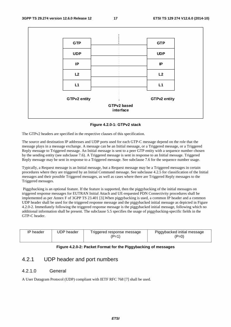
ETSI
ETSI TS 129 274 V12.6.0 (2014-10)173GPP TS 29.274 version 12.6.0 Release 12
GTP
UDP
IP
L2
L1
GTP
UDP
IP
L2
L1
GTPv2 entity GTPv2 entity
GTPv2 based interface
Figure 4.2.0-1: GTPv2 stack
The GTPv2 headers are specified in the respective clauses of this specification.
The source and destination IP addresses and UDP ports used for each GTP-C message depend on the role that the message plays in a message exchange. A message can be an Initial message, or a Triggered message, or a Triggered Reply message to Triggered message. An Initial message is sent to a peer GTP entity with a sequence number chosen by the sending entity (see subclause 7.6). A Triggered message is sent in response to an Initial message. Triggered Reply message may be sent in response to a Triggered message. See subclause 7.6 for the sequence number usage.
Typically, a Request message is an Initial message, but a Request message may be a Triggered messages in certain procedures where they are triggered by an Initial Command message. See subclause 4.2.5 for classification of the Initial messages and their possible Triggered messages, as well as cases where there are Triggered Reply messages to the Triggered messages.
Piggybacking is an optional feature. If the feature is supported, then the piggybacking of the initial messages on triggered response messages for EUTRAN Initial Attach and UE-requested PDN Connectivity procedures shall be implemented as per Annex F of 3GPP TS 23.401 [3].When piggybacking is used, a common IP header and a common UDP header shall be used for the triggered response message and the piggybacked initial message as depicted in Figure 4.2.0-2. Immediately following the triggered response message is the piggybacked initial message, following which no additional information shall be present. The subclause 5.5 specifies the usage of piggybacking-specific fields in the GTP-C header.
IP header UDP header Triggered response message (P=1)
Piggybacked initial message (P=0)
Figure 4.2.0-2: Packet Format for the Piggybacking of messages
4.2.1 UDP header and port numbers
4.2.1.0 General
A User Datagram Protocol (UDP) compliant with IETF RFC 768 [7] shall be used.
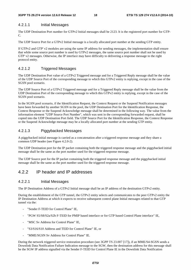
ETSI
ETSI TS 129 274 V12.6.0 (2014-10)183GPP TS 29.274 version 12.6.0 Release 12
4.2.1.1 Initial Messages
The UDP Destination Port number for GTPv2 Initial messages shall be 2123. It is the registered port number for GTP-C.
The UDP Source Port for a GTPv2 Initial message is a locally allocated port number at the sending GTP entity.
If GTPv2 and GTP' v2 modules are using the same IP address for sending messages, the implementation shall ensure that while some source port number is used by GTPv2 messages, the same source port number shall not be used by GTP' v2 messages. Otherwise, the IP interface may have difficulty to delivering a response message to the right protocol entity.
4.2.1.2 Triggered Messages
The UDP Destination Port value of a GTPv2 Triggered message and for a Triggered Reply message shall be the value of the UDP Source Port of the corresponding message to which this GTPv2 entity is replying, except in the case of the SGSN pool scenario.
The UDP Source Port of a GTPv2 Triggered message and for a Triggered Reply message shall be the value from the UDP Destination Port of the corresponding message to which this GTPv2 entity is replying, except in the case of the SGSN pool scenario.
In the SGSN pool scenario, if the Identification Request, the Context Request or the Suspend Notification messages have been forwarded by another SGSN in the pool, the UDP Destination Port for the Identification Response, the Context Response or the Suspend Acknowledge message shall be determined in the following way. The value from the information element "UDP Source Port Number", which was sent in the corresponding forwarded request, shall be copied into the UDP Destination Port field. The UDP Source Port for the Identification Response, the Context Response or the Suspend Acknowledge message may be a locally allocated port number at the sending GTP entity.
4.2.1.3 Piggybacked Messages
A piggybacked initial message is carried as a concatenation after a triggered response message and they share a common UDP header (see Figure 4.2.0-2).
The UDP Destination port for the IP packet containing both the triggered response message and the piggybacked initial message shall be the same as the port number used for the triggered response message. The UDP Source port for the IP packet containing both the triggered response message and the piggybacked initial message shall be the same as the port number used for the triggered response message.
4.2.2 IP header and IP addresses
4.2.2.1 Initial Messages
The IP Destination Address of a GTPv2 Initial message shall be an IP address of the destination GTPv2 entity.
During the establishment of the GTP tunnel, the GTPv2 entity selects and communicates to the peer GTPv2 entity the IP Destination Address at which it expects to receive subsequent control plane Initial messages related to that GTP tunnel via the:
- "Sender F-TEID for Control Plane" IE,
- "PGW S5/S8/S2a/S2b F-TEID for PMIP based interface or for GTP based Control Plane interface" IE,
- "MSC Sv Address for Control Plane" IE,
- "S3/S16/S10 Address and TEID for Control Plane" IE, or
- "MME/SGSN Sv Address for Control Plane" IE.
During the network triggered service restoration procedure (see 3GPP TS 23.007 [17]), if an MME/S4-SGSN sends a Downlink Data Notification Failure Indication message to the SGW, then the destination address for this message shall be the SGW IP address signalled via the Sender F-TEID for Control Plane IE in the Downlink Data Notification
ETSI
ETSI TS 129 274 V12.6.0 (2014-10)193GPP TS 29.274 version 12.6.0 Release 12
message (if present in the message), otherwise the source IP address of the Downlink Data Notification message received earlier.
The IP Source Address of a GTPv2 Initial message shall be an IP address of the source GTPv2 entity from which the Initial message is originating.
4.2.2.2 Triggered Messages
The IP Destination Address of a GTPv2 Triggered message and for a Triggered Reply message shall be copied from the IP Source Address of the message to which this GTPv2 entity is replying, except in the case of the SGSN pool scenario.
The IP Source Address of a GTPv2 Triggered message and for a Triggered Reply message shall be copied from the IP destination address of the message to which this GTPv2 entity is replying, except in the case of SGSN pool scenario.
In the SGSN pool scenario, if the Identification Request, the Context Request or the Suspend Notification messages have been forwarded by another SGSN in the pool, the IP Source address for the Identification Response, the Context Response or the Suspend Acknowledge messages shall be locally allocated by the sending GTP entity. The IP Destination Address for the Identification Response, the Context Response or the Suspend Acknowlegde messages shall be determined in the following way. The value from the information element "Address for Control Plane", which was sent in the corresponding Identification Request or the Suspend Notification message; or the value from the information element "S3/S16/S10 Address and TEID for Control Plane", which was sent in the corresponding Context Request message, shall be copied into the IP Destination Address field.
4.2.2.3 Piggybacked Messages
A piggybacked initial message is carried as a concatenation after a triggered response message and they share a common IP header (see Figure 4.2.0-2).
The IP Source Address for the IP packet containing both the triggered response message and the piggybacked initial message shall be the same as the IP Address used for the triggered response message.
The IP Destination Address for the IP packet containing both the triggered response message and the piggybacked initial message shall be the same as the IP Address used for the triggered response message.
4.2.3 Layer 2
Typically Ethernet should be used as a Layer 2 protocol, but operators may use any other technology.
4.2.4 Layer 1
Operators may use any appropriate Layer 1 technology.
4.2.5 Messages with GTPv2 defined replies: Classification of Initial and Triggered Messages
An Initial message is a GTPv2 message that is not triggered as a response to another GTPv2 message across the given interface.
The expected reply to a Request message is a Triggered message and the reply has the same message name as the Request but with "Response" replacing "Request".
NOTE 1: If the SGW receives a "Create Session Request" on S11/S4, this can trigger either of the following GTPv2 messages across S5/S8: "Create Session Request" or "Modify Bearer Request". However, neither of these messages across S5/S8 is considered to be a Triggered message.
If a Request message is a reply to a Command message, then the Request message is a Triggered message; otherwise the Request message is an Initial message. Responses do not have replies except when a "Context Acknowledge" is required as a reply to "Context Response" message as specified in relevant Stage 2 procedures. Context Acknowledge is always triggered message and does not have a reply.
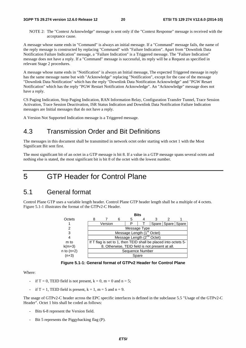
ETSI
ETSI TS 129 274 V12.6.0 (2014-10)203GPP TS 29.274 version 12.6.0 Release 12
NOTE 2: The "Context Acknowledge" message is sent only if the "Context Response" message is received with the acceptance cause.
A message whose name ends in "Command" is always an initial message. If a "Command" message fails, the name of the reply message is constructed by replacing "Command" with "Failure Indication". Apart from "Downlink Data Notification Failure Indication" message, a "Failure Indication" is a Triggered message. The "Failure Indication" message does not have a reply. If a "Command" message is successful, its reply will be a Request as specified in relevant Stage 2 procedures.
A message whose name ends in "Notification" is always an Initial message, The expected Triggered message in reply has the same message name but with "Acknowledge" replacing "Notification", except for the case of the message "Downlink Data Notification" which has the reply "Downlink Data Notification Acknowledge" and "PGW Resart Notification" which has the reply "PGW Restart Notification Acknowledge". An "Acknowledge" message does not have a reply.
CS Paging Indication, Stop Paging Indication, RAN Information Relay, Configuration Transfer Tunnel, Trace Session Activation, Trace Session Deactivation, ISR Status Indication and Downlink Data Notification Failure Indication messages are Initial messages that do not have a reply.
A Version Not Supported Indication message is a Triggered message.
4.3 Transmission Order and Bit Definitions The messages in this document shall be transmitted in network octet order starting with octet 1 with the Most Significant Bit sent first.
The most significant bit of an octet in a GTP message is bit 8. If a value in a GTP message spans several octets and nothing else is stated, the most significant bit is bit 8 of the octet with the lowest number.
5 GTP Header for Control Plane
5.1 General format Control Plane GTP uses a variable length header. Control Plane GTP header length shall be a multiple of 4 octets. Figure 5.1-1 illustrates the format of the GTPv2-C Header.
Bits Octets 8 7 6 5 4 3 2 1
1 Version P T Spare Spare Spare 2 Message Type 3 Message Length (1st Octet) 4 Message Length (2nd Octet)
m to k(m+3)
If T flag is set to 1, then TEID shall be placed into octets 5-8. Otherwise, TEID field is not present at all.
n to (n+2) Sequence Number (n+3) Spare
Figure 5.1-1: General format of GTPv2 Header for Control Plane
Where:
- if T = 0, TEID field is not present, k = 0, m = 0 and n = 5;
- if T = 1, TEID field is present, k = 1, m = 5 and n = 9.
The usage of GTPv2-C header across the EPC specific interfaces is defined in the subclause 5.5 "Usage of the GTPv2-C Header". Octet 1 bits shall be coded as follows:
- Bits 6-8 represent the Version field.
- Bit 5 represents the Piggybacking flag (P).
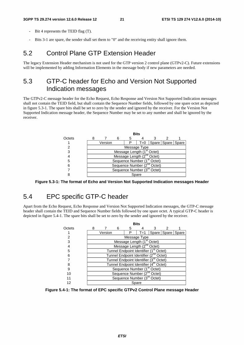
ETSI
ETSI TS 129 274 V12.6.0 (2014-10)213GPP TS 29.274 version 12.6.0 Release 12
- Bit 4 represents the TEID flag (T).
- Bits 3-1 are spare, the sender shall set them to "0" and the receiving entity shall ignore them.
5.2 Control Plane GTP Extension Header The legacy Extension Header mechanism is not used for the GTP version 2 control plane (GTPv2-C). Future extensions will be implemented by adding Information Elements in the message body if new parameters are needed.
5.3 GTP-C header for Echo and Version Not Supported Indication messages
The GTPv2-C message header for the Echo Request, Echo Response and Version Not Supported Indication messages shall not contain the TEID field, but shall contain the Sequence Number fields, followed by one spare octet as depicted in figure 5.3-1. The spare bits shall be set to zero by the sender and ignored by the receiver. For the Version Not Supported Indication message header, the Sequence Number may be set to any number and shall be ignored by the receiver.
Bits Octets 8 7 6 5 4 3 2 1
1 Version P T=0 Spare Spare Spare 2 Message Type 3 Message Length (1st Octet) 4 Message Length (2nd Octet) 5 Sequence Number (1st Octet) 6 Sequence Number (2nd Octet) 7 Sequence Number (3rd Octet) 8 Spare
Figure 5.3-1: The format of Echo and Version Not Supported Indication messages Header
5.4 EPC specific GTP-C header Apart from the Echo Request, Echo Response and Version Not Supported Indication messages, the GTP-C message header shall contain the TEID and Sequence Number fields followed by one spare octet. A typical GTP-C header is depicted in figure 5.4-1. The spare bits shall be set to zero by the sender and ignored by the receiver.
Bits Octets 8 7 6 5 4 3 2 1
1 Version P T=1 Spare Spare Spare 2 Message Type 3 Message Length (1st Octet) 4 Message Length (2nd Octet) 5 Tunnel Endpoint Identifier (1st Octet) 6 Tunnel Endpoint Identifier (2nd Octet) 7 Tunnel Endpoint Identifier (3rd Octet) 8 Tunnel Endpoint Identifier (4th Octet) 9 Sequence Number (1st Octet)
10 Sequence Number (2nd Octet) 11 Sequence Number (3rd Octet) 12 Spare
Figure 5.4-1: The format of EPC specific GTPv2 Control Plane message Header
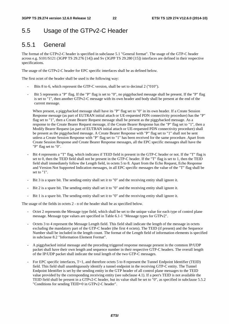
ETSI
ETSI TS 129 274 V12.6.0 (2014-10)223GPP TS 29.274 version 12.6.0 Release 12
5.5 Usage of the GTPv2-C Header
5.5.1 General The format of the GTPv2-C header is specified in subclause 5.1 "General format". The usage of the GTP-C header across e.g. S101/S121 (3GPP TS 29.276 [14]) and Sv (3GPP TS 29.280 [15]) interfaces are defined in their respective specifications.
The usage of the GTPv2-C header for EPC specific interfaces shall be as defined below.
The first octet of the header shall be used is the following way:
- Bits 8 to 6, which represent the GTP-C version, shall be set to decimal 2 ("010").
- Bit 5 represents a "P" flag. If the "P" flag is set to "0", no piggybacked message shall be present. If the "P" flag is set to "1", then another GTPv2-C message with its own header and body shall be present at the end of the current message.
When present, a piggybacked message shall have its "P" flag set to "0" in its own header. If a Create Session Response message (as part of EUTRAN initial attach or UE-requested PDN connectivity procedure) has the "P" flag set to "1", then a Create Bearer Request message shall be present as the piggybacked message. As a response to the Create Bearer Request message, if the Create Bearer Response has the "P" flag set to "1", then a Modify Bearer Request (as part of EUTRAN initial attach or UE-requested PDN connectivity procedure) shall be present as the piggybacked message. A Create Bearer Response with "P" flag set to "1" shall not be sent unless a Create Session Response with "P" flag set to "1" has been received for the same procedure. Apart from Create Session Response and Create Bearer Response messages, all the EPC specific messages shall have the "P" flag set to "0".
- Bit 4 represents a "T" flag, which indicates if TEID field is present in the GTP-C header or not. If the "T" flag is set to 0, then the TEID field shall not be present in the GTP-C header. If the "T" flag is set to 1, then the TEID field shall immediately follow the Length field, in octets 5 to 8. Apart from the Echo Request, Echo Response and Version Not Supported Indication messages, in all EPC specific messages the value of the "T" flag shall be set to "1".
- Bit 3 is a spare bit. The sending entity shall set it to "0" and the receiving entity shall ignore it.
- Bit 2 is a spare bit. The sending entity shall set it to "0" and the receiving entity shall ignore it.
- Bit 1 is a spare bit. The sending entity shall set it to "0" and the receiving entity shall ignore it.
The usage of the fields in octets 2 - n of the header shall be as specified below.
- Octet 2 represents the Message type field, which shall be set to the unique value for each type of control plane message. Message type values are specified in Table 6.1-1 "Message types for GTPv2".
- Octets 3 to 4 represent the Message Length field. This field shall indicate the length of the message in octets excluding the mandatory part of the GTP-C header (the first 4 octets). The TEID (if present) and the Sequence Number shall be included in the length count. The format of the Length field of information elements is specified in subclause 8.2 "Information Element Format".
- A piggybacked initial message and the preceding triggered response message present in the common IP/UDP packet shall have their own length and sequence number in their respective GTP-C headers. The overall length of the IP/UDP packet shall indicate the total length of the two GTP-C messages.
- For EPC specific interfaces, T=1, and therefore octets 5 to 8 represent the Tunnel Endpoint Identifier (TEID) field. This field shall unambiguously identify a tunnel endpoint in the receiving GTP-C entity. The Tunnel Endpoint Identifier is set by the sending entity in the GTP header of all control plane messages to the TEID value provided by the corresponding receiving entity (see subclause 4.1). If a peer's TEID is not available the TEID field shall be present in a GTPv2-C header, but its value shall be set to "0", as specified in subclause 5.5.2 "Conditions for sending TEID=0 in GTPv2-C header".
ETSI
ETSI TS 129 274 V12.6.0 (2014-10)233GPP TS 29.274 version 12.6.0 Release 12
NOTE: The TEID in the GTP header of a Triggered (or Triggered Reply) message is set to the TEID value provided by the corresponding receiving entity regardless of whether the source IP address of the Initial (or Triggered) message and the IP Destination Address provided by the receiving entity for subsequent control plane Initial messages (see subclause 4.2.2.1) are the same or not.
- Octets 9 to 11 represent GTP Sequence Number field.
5.5.2 Conditions for sending TEID=0 in GTPv2-C header
If a peer's TEID is not available, the TEID field still shall be present in the header and its value shall be set to "0" in the following messages:
- Create Session Request message on S2a/S2b/S5/S8
- Create Session Request message on S4/S11, if for a given UE, the SGSN/MME has not yet obtained the Control TEID of the SGW.
- Create Indirect Data Forwarding Tunnel Request message on S4/S11, if the SGW selected by the MME/S4-SGSN for indirect data forwarding is different from the SGW used as anchor.
- Identification Request/Response messages.
- Forward Relocation Request message: over S10, S16 interfaces, over S3 interface during I-RAT handover when ISR is not active.
- Forward Relocation Request message over S3 interface during I-RAT handover between ISR associated nodes, when ISR is active for the UE, and if the node decides to allocate new S3 TEID-C.
- Context Request message.
- Relocation Cancel Request message except for the case where the old SGSN/MME has already been assigned the Tunnel Endpoint Identifier Control Plane of the new SGSN/MME.
- Relocation Cancel Response message if the new SGSN/MME does not have the Tunnel Endpoint Identifier Control Plane of the old SGSN/MME.
- Delete PDN Connection Set Request/Response messages.
- Configuration Transfer Tunnel message.
- RAN Information Relay message.
- If a node receives a message for which it has no context, i.e. TEID-C is not known, it shall respond with "Context not found" Cause in the corresponding response message to the sender, the TEID used in the GTPv2-C header in the response message shall be then set to zero.
- If a node receives a request message containing protocol error, e.g. Mandatory IE missing, which requires the receiver to reject the message as specified in clause 7.7, it shall reject the request message. For the response message, the node should look up the remote peer"s TEID and accordingly set the GTPv2-C header TEID and the message cause code. As an implementation option, the node may not look up the remote peer"s TEID and set the GTPv2-C header TEID to zero in the response message. However in this case, the cause code shall not be set to "Context not found".
- MBMS Session Start Request message.
- PGW Restart Notification / PGW Restart Notification Acknowledge messages.
- Downlink Data Notification message sent on S11/S4 as part of the Network Triggered Service Restoration procedure (see 3GPP TS 23.007 [17]), and corresponding Downlink Data Notification Acknowledge and Downlink Data Notification Failure Indication if the SGW did not include the Sender F-TEID for Control Plane IE in the Downlink Data Notification message.
- Stop Paging Indication message is sent to the the restarted CN node (or another node in the same pool) as part of the Network Triggered Service Restoration procedure with ISR (see 3GPP TS 23.007 [17]).
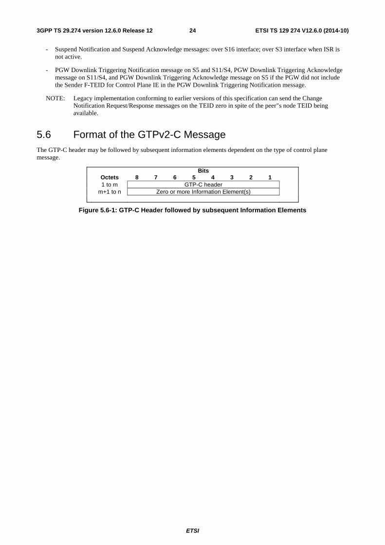
ETSI
ETSI TS 129 274 V12.6.0 (2014-10)243GPP TS 29.274 version 12.6.0 Release 12
- Suspend Notification and Suspend Acknowledge messages: over S16 interface; over S3 interface when ISR is not active.
- PGW Downlink Triggering Notification message on S5 and S11/S4, PGW Downlink Triggering Acknowledge message on S11/S4, and PGW Downlink Triggering Acknowledge message on S5 if the PGW did not include the Sender F-TEID for Control Plane IE in the PGW Downlink Triggering Notification message.
NOTE: Legacy implementation conforming to earlier versions of this specification can send the Change Notification Request/Response messages on the TEID zero in spite of the peer"s node TEID being available.
5.6 Format of the GTPv2-C Message The GTP-C header may be followed by subsequent information elements dependent on the type of control plane message.
Bits Octets 8 7 6 5 4 3 2 1 1 to m GTP-C header m+1 to n Zero or more Information Element(s)
Figure 5.6-1: GTP-C Header followed by subsequent Information Elements
ETSI
ETSI TS 129 274 V12.6.0 (2014-10)253GPP TS 29.274 version 12.6.0 Release 12
6 GTP-C Message Types and Message Formats
6.0 General A GTP-C message is sent across a GTP control plane tunnel. In a message, the GTP-C header is followed by zero or more information elements. The GTP-C messages are used for the control plane path management, for the control plane tunnel management and for mobility management.
A T-PDU is an original packet, for example an IP datagram, from an UE, or from a network node in an external packet data network.
6.1 Message Format and Type values
6.1.0 Message Type
GTP defines a set of messages between two associated EPC network elements. The messages to be used shall be as defined in Table 6.1-1.
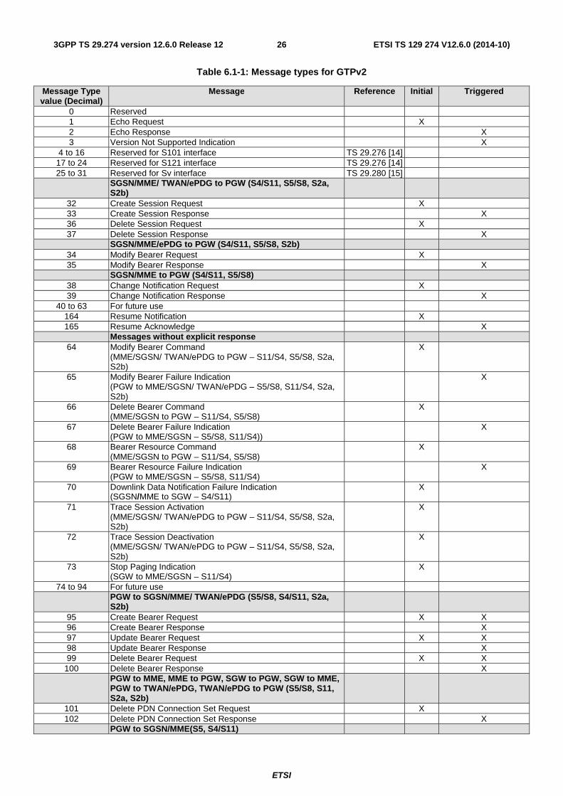
ETSI
ETSI TS 129 274 V12.6.0 (2014-10)263GPP TS 29.274 version 12.6.0 Release 12
Table 6.1-1: Message types for GTPv2
Message Type value (Decimal)
Message Reference Initial Triggered
0 Reserved 1 Echo Request X 2 Echo Response X 3 Version Not Supported Indication X
4 to 16 Reserved for S101 interface TS 29.276 [14] 17 to 24 Reserved for S121 interface TS 29.276 [14] 25 to 31 Reserved for Sv interface TS 29.280 [15]
SGSN/MME/ TWAN/ePDG to PGW (S4/S11, S5/S8, S2a, S2b)
32 Create Session Request X 33 Create Session Response X 36 Delete Session Request X 37 Delete Session Response X SGSN/MME/ePDG to PGW (S4/S11, S5/S8, S2b)
34 Modify Bearer Request X 35 Modify Bearer Response X SGSN/MME to PGW (S4/S11, S5/S8)
38 Change Notification Request X 39 Change Notification Response X
40 to 63 For future use 164 Resume Notification X 165 Resume Acknowledge X
Messages without explicit response 64 Modify Bearer Command
(MME/SGSN/ TWAN/ePDG to PGW – S11/S4, S5/S8, S2a, S2b)
X
65 Modify Bearer Failure Indication (PGW to MME/SGSN/ TWAN/ePDG – S5/S8, S11/S4, S2a, S2b)
X
66 Delete Bearer Command (MME/SGSN to PGW – S11/S4, S5/S8)
X
67 Delete Bearer Failure Indication (PGW to MME/SGSN – S5/S8, S11/S4))
X
68 Bearer Resource Command (MME/SGSN to PGW – S11/S4, S5/S8)
X
69 Bearer Resource Failure Indication (PGW to MME/SGSN – S5/S8, S11/S4)
X
70 Downlink Data Notification Failure Indication (SGSN/MME to SGW – S4/S11)
X
71 Trace Session Activation (MME/SGSN/ TWAN/ePDG to PGW – S11/S4, S5/S8, S2a, S2b)
X
72 Trace Session Deactivation (MME/SGSN/ TWAN/ePDG to PGW – S11/S4, S5/S8, S2a, S2b)
X
73 Stop Paging Indication (SGW to MME/SGSN – S11/S4)
X
74 to 94 For future use PGW to SGSN/MME/ TWAN/ePDG (S5/S8, S4/S11, S2a,
S2b)
95 Create Bearer Request X X 96 Create Bearer Response X 97 Update Bearer Request X X 98 Update Bearer Response X 99 Delete Bearer Request X X
100 Delete Bearer Response X PGW to MME, MME to PGW, SGW to PGW, SGW to MME,
PGW to TWAN/ePDG, TWAN/ePDG to PGW (S5/S8, S11, S2a, S2b)
101 Delete PDN Connection Set Request X 102 Delete PDN Connection Set Response X
PGW to SGSN/MME(S5, S4/S11)
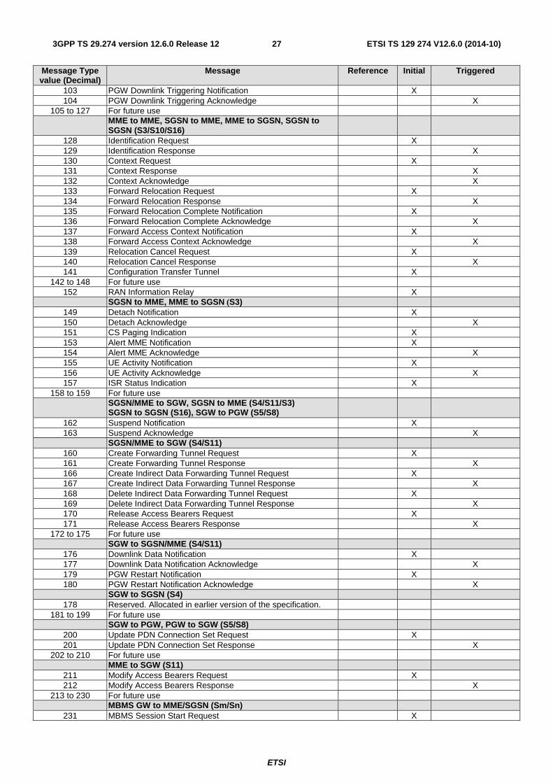
ETSI
ETSI TS 129 274 V12.6.0 (2014-10)273GPP TS 29.274 version 12.6.0 Release 12
Message Type value (Decimal)
Message Reference Initial Triggered
103 PGW Downlink Triggering Notification X 104 PGW Downlink Triggering Acknowledge X
105 to 127 For future use MME to MME, SGSN to MME, MME to SGSN, SGSN to
SGSN (S3/S10/S16)
128 Identification Request X 129 Identification Response X 130 Context Request X 131 Context Response X 132 Context Acknowledge X 133 Forward Relocation Request X 134 Forward Relocation Response X 135 Forward Relocation Complete Notification X 136 Forward Relocation Complete Acknowledge X 137 Forward Access Context Notification X 138 Forward Access Context Acknowledge X 139 Relocation Cancel Request X 140 Relocation Cancel Response X 141 Configuration Transfer Tunnel X
142 to 148 For future use 152 RAN Information Relay X
SGSN to MME, MME to SGSN (S3) 149 Detach Notification X 150 Detach Acknowledge X 151 CS Paging Indication X 153 Alert MME Notification X 154 Alert MME Acknowledge X 155 UE Activity Notification X 156 UE Activity Acknowledge X 157 ISR Status Indication X
158 to 159 For future use SGSN/MME to SGW, SGSN to MME (S4/S11/S3)
SGSN to SGSN (S16), SGW to PGW (S5/S8)
162 Suspend Notification X 163 Suspend Acknowledge X
SGSN/MME to SGW (S4/S11) 160 Create Forwarding Tunnel Request X 161 Create Forwarding Tunnel Response X 166 Create Indirect Data Forwarding Tunnel Request X 167 Create Indirect Data Forwarding Tunnel Response X 168 Delete Indirect Data Forwarding Tunnel Request X 169 Delete Indirect Data Forwarding Tunnel Response X 170 Release Access Bearers Request X 171 Release Access Bearers Response X
172 to 175 For future use SGW to SGSN/MME (S4/S11)
176 Downlink Data Notification X 177 Downlink Data Notification Acknowledge X 179 PGW Restart Notification X 180 PGW Restart Notification Acknowledge X
SGW to SGSN (S4) 178 Reserved. Allocated in earlier version of the specification.
181 to 199 For future use SGW to PGW, PGW to SGW (S5/S8)
200 Update PDN Connection Set Request X 201 Update PDN Connection Set Response X
202 to 210 For future use MME to SGW (S11)
211 Modify Access Bearers Request X 212 Modify Access Bearers Response X
213 to 230 For future use MBMS GW to MME/SGSN (Sm/Sn)
231 MBMS Session Start Request X
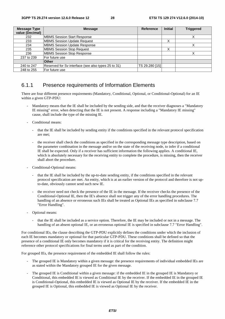
ETSI
ETSI TS 129 274 V12.6.0 (2014-10)283GPP TS 29.274 version 12.6.0 Release 12
Message Type value (Decimal)
Message Reference Initial Triggered
232 MBMS Session Start Response X 233 MBMS Session Update Request X 234 MBMS Session Update Response X 235 MBMS Session Stop Request X 236 MBMS Session Stop Response X
237 to 239 For future use Other
240 to 247 Reserved for Sv interface (see also types 25 to 31) TS 29.280 [15] 248 to 255 For future use
6.1.1 Presence requirements of Information Elements
There are four different presence requirements (Mandatory, Conditional, Optional, or Conditional-Optional) for an IE within a given GTP-PDU:
- Mandatory means that the IE shall be included by the sending side, and that the receiver diagnoses a "Mandatory IE missing" error, when detecting that the IE is not present. A response including a "Mandatory IE missing" cause, shall include the type of the missing IE.
- Conditional means:
- that the IE shall be included by sending entity if the conditions specified in the relevant protocol specification are met;
- the receiver shall check the conditions as specified in the corresponding message type description, based on the parameter combination in the message and/or on the state of the receiving node, to infer if a conditional IE shall be expected. Only if a receiver has sufficient information the following applies. A conditional IE, which is absolutely necessary for the receiving entity to complete the procedure, is missing, then the receiver shall abort the procedure.
- Conditional-Optional means:
- that the IE shall be included by the up-to-date sending entity, if the conditions specified in the relevant protocol specification are met. An entity, which is at an earlier version of the protocol and therefore is not up-to-date, obviously cannot send such new IE.
- the receiver need not check the presence of the IE in the message. If the receiver checks the presence of the Conditional-Optional IE, then the IE's absence shall not trigger any of the error handling procedures. The handling of an absence or erroneous such IEs shall be treated as Optional IEs as specified in subclause 7.7 "Error Handling".
- Optional means:
- that the IE shall be included as a service option. Therefore, the IE may be included or not in a message. The handling of an absent optional IE, or an erroneous optional IE is specified in subclause 7.7 "Error Handling".
For conditional IEs, the clause describing the GTP-PDU explicitly defines the conditions under which the inclusion of each IE becomes mandatory or optional for that particular GTP-PDU. These conditions shall be defined so that the presence of a conditional IE only becomes mandatory if it is critical for the receiving entity. The definition might reference other protocol specifications for final terms used as part of the condition.
For grouped IEs, the presence requirement of the embedded IE shall follow the rules:
- The grouped IE is Mandatory within a given message: the presence requirements of individual embedded IEs are as stated within the Mandatory grouped IE for the given message.
- The grouped IE is Conditional within a given message: if the embedded IE in the grouped IE is Mandatory or Conditional, this embedded IE is viewed as Conditional IE by the receiver. If the embedded IE in the grouped IE is Conditional-Optional, this embedded IE is viewed as Optional IE by the receiver. If the embedded IE in the grouped IE is Optional, this embedded IE is viewed as Optional IE by the receiver.
ETSI
ETSI TS 129 274 V12.6.0 (2014-10)293GPP TS 29.274 version 12.6.0 Release 12
- The grouped IE is Conditional-Optional within a given message: if the embedded IE in the grouped IE is Mandatory or Conditional, this embedded IE is viewed as Conditional-Optional IE by the receiver. If the embedded IE in the grouped IE is Conditional-Optional, this embedded IE is viewed as Optional IE by the receiver. If the embedded IE in the grouped IE is Optional, this embedded IE is viewed as Optional IE by the receiver.
- The grouped IE is Optional within a given message: all embedded IEs in the grouped IE are viewed as Optional IEs by the receiver.
In all of the above cases, appropriate error handling as described in subclause 7.7 shall be applied for protocol errors of the embedded IEs.
Only the Cause information element at message level shall be included in the response if the Cause contains a value that indicates that the request is not accepted regardless of whether there are other mandatory or conditional information elements defined for a given response message.
The following are exceptions:
- Optionally, the Protocol Configuration Options, Recovery, User Location Information (ULI), Load Control Information, Overload Control Information, Bearer Context and Local Distinguished Name (LDN) information elements may be included.
- For the rejection response of a Forward Relocation Request, the Forward Relocation Response message may also include an F-Cause IE as specified in clause 7.3.2.
- For the rejection response of a SRVCC PS to CS Request, the SRVCC PS to CS Response message may also include an SRVCC Cause IE as specified in clause 5.2.3 in 3GPP TS 29.280 [15].
- A Downlink Data Notification Acknowledge (with or) without an indication of success may also include a DL low priority traffic Throttling IE and the IMSI IE.
- The PGW Back-Off Time IE may also be returned when rejecting a Create Session Request with the cause "APN Congestion".
- Change Notification Response message may also include the IMSI and MEI information elements.
- Failure Indication type messages do not have "Accept" types of cause values i.e. all used values indicate the rejection, therefore the preceding rules do not apply. For Failure Indication type of triggered messages, some of the Mandatory information elements, other than the Cause IE, may not be included if they are not available.
- The Context Response message (sent by an SGSN or MME) should also include the IMSI IE if the Cause IE contains the value "P-TMSI Signature mismatch", except if the UE is emergency attached and the UE is UICCless.
- The Create Bearer Response message and the Update Bearer Response message shall include the RAN/NAS Cause IE according to the conditions specified in subclauses 7.2.4 and 7.2.16.
6.1.2 Grouped Information Elements
Information elements can contain other IEs. This type of IE is called "Grouped IEs".
Grouped IEs have a length value in the TLIV encoding, which includes the added length of all the embedded IEs. Overall coding of a grouped information element with 4 octets long IE header is defined in subclause 8.2 "Information Element Format". Each information element within a grouped IE also shall also contain 4 octets long IE header.
Grouped IEs are not marked by any flag or limited to a specific range of IE type values. The clause describing an IE in this specification shall explicitly state if it is grouped.
NOTE 1: Each entry into each Grouped IE creates a new scope level. Exit from the grouped IE closes the scope level. The GTPv2 message level is the top most scope. This is analogous to the local scope of a subroutine/function.
If more than one grouped information elements of the same type, but for a different purpose are sent with a message, these IEs shall have different Instance values.
ETSI
ETSI TS 129 274 V12.6.0 (2014-10)303GPP TS 29.274 version 12.6.0 Release 12
If more than one grouped information elements of the same type and for the same purpose are sent with a message, these IEs shall have exactly the same Instance value to represent a list.
NOTE 2: For instance, all "Bearer Contexts Modified" IEs of the type "Bearer Context" in a "Modify Bearer Response" message shall have the Instance value of 0, while all "Bearer Contexts Marked for Removal" IEs of the type "Bearer Context" in the same message shall have the Instance value of 1.
6.1.3 Information Element instance
Every GTPv2 message and grouped IE within a message in this specification has a column documenting the instance value of each IE.
When a GTPv2 message is encoded for use the instance value of each included IE is encoded in the Instance field of the IE for the message scope. See clause 7 and subclause 8.2 for details of that encoding.
An Information Element in an encoded GTPv2 message or encoded grouped IE is identified by the pair of IE Type and Instance values and described by a specific row in the corresponding tables in subclauses of 7 in the present document.
If several Information Elements with the same Type and Instance values are included in an encoded GTPv2 message, they represent a list for the corresponding IE name and row identified in the message grammar in subclauses of clause 7.
If several Information Elements with the same Type and Instance values are included in an encoded grouped IE, they represent a list for the corresponding IE name and row identified in the grouped IE grammar in subclauses of clause 7.
In tables in this document the instance value for "Private Extension" is marked as VS (Vendor Specific). While an instance value must be encoded by the sender the value can be Vendor and even Private Extension specific.
The same IE name might be used in different messages (on the top level or within grouped IEs) in this specification. The instance value and name of an IE is only meaningful within the scope of the message definition . The combination of Type value and Instance value uniquely identifies a specific row in a message description table.
6.2 Message Granularity The GTPv2-C messages shall be sent per UE on the S3, S10 and S16 interfaces.
The GTPv2-C messages shall be sent per PDN-Connection on the S2a, S2b, S4, S11, S5 and S8 interfaces apart from the following exclusion.
The following GTPv2-C messages are sent per UE on the S4 and S11 interfaces:
- Downlink Data Notification / Acknowledge / Failure Indication;
- Stop Paging Indication;
- Delete Indirect Data Forwarding Tunnel Request/Response;
- Delete Session Request/Response with Scope Indication set to 1 during following procedures with SGW change:
- Tracking Area Update procedure;
- Routing Area Update procedure;
- Handover procedure;
- SRNS Relocation Cancel Using S4;
- Inter RAT handover Cancel procedure;
- S1 based handover cancel procedure;
- Delete Bearer Request/Response during a TAU/RAU/Handover procedure if the Cause value "ISR deactivation" is included in the Delete Session Request message, or when it is sent to delete the bearer resources on the other ISR associated CN node if the ISRAI flag is not set in the Modify Bearer Request/Modify Access Bearers Request message.
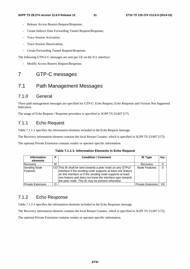
ETSI
ETSI TS 129 274 V12.6.0 (2014-10)313GPP TS 29.274 version 12.6.0 Release 12
- Release Access Bearers Request/Response;
- Create Indirect Data Forwarding Tunnel Request/Response;
- Trace Session Activation;
- Trace Session Deactivation;
- Create Forwarding Tunnel Request/Response.
The following GTPv2-C messages are sent per UE on the S11 interface:
- Modify Access Bearers Request/Response.
7 GTP-C messages
7.1 Path Management Messages
7.1.0 General
Three path management messages are specified for GTP-C: Echo Request, Echo Response and Version Not Supported Indication.
The usage of Echo Request / Response procedure is specified in 3GPP TS 23.007 [17].
7.1.1 Echo Request
Table 7.1.1-1 specifies the information elements included in the Echo Request message.
The Recovery information element contains the local Restart Counter, which is specified in 3GPP TS 23.007 [17])
The optional Private Extension contains vendor or operator specific information.
Table 7.1.1-1: Information Elements in Echo Request
Information elements
P Condition / Comment IE Type Ins.
Recovery M Recovery 0 Sending Node Features
CO This IE shall be sent towards a peer node on any GTPv2 interface if the sending node supports at least one feature on this interface or if the sending node supports at least one feature and does not know the interface type towards the peer node. This IE may be present otherwise.
Node Features 0
Private Extension O Private Extension VS
7.1.2 Echo Response
Table 7.1.2-1 specifies the information elements included in the Echo Response message.
The Recovery information element contains the local Restart Counter, which is specified in 3GPP TS 23.007 [17])
The optional Private Extension contains vendor or operator specific information.
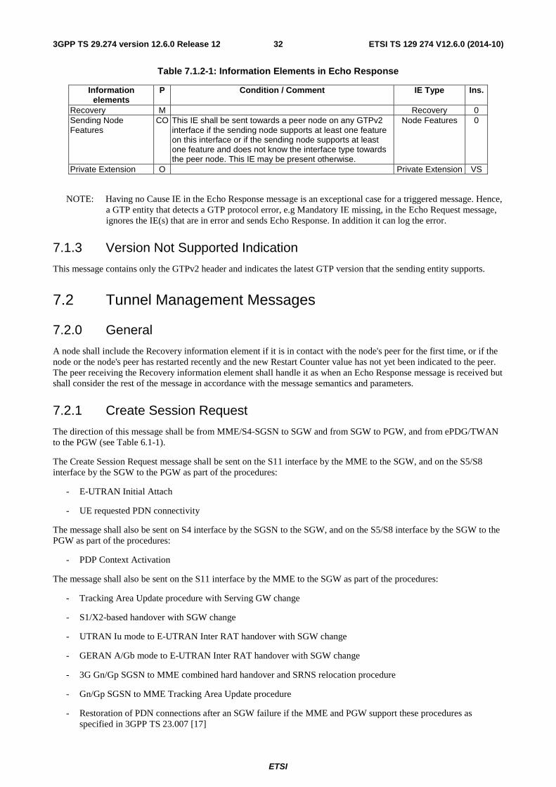
ETSI
ETSI TS 129 274 V12.6.0 (2014-10)323GPP TS 29.274 version 12.6.0 Release 12
Table 7.1.2-1: Information Elements in Echo Response
Information elements
P Condition / Comment IE Type Ins.
Recovery M Recovery 0 Sending Node Features
CO This IE shall be sent towards a peer node on any GTPv2 interface if the sending node supports at least one feature on this interface or if the sending node supports at least one feature and does not know the interface type towards the peer node. This IE may be present otherwise.
Node Features 0
Private Extension O Private Extension VS
NOTE: Having no Cause IE in the Echo Response message is an exceptional case for a triggered message. Hence, a GTP entity that detects a GTP protocol error, e.g Mandatory IE missing, in the Echo Request message, ignores the IE(s) that are in error and sends Echo Response. In addition it can log the error.
7.1.3 Version Not Supported Indication
This message contains only the GTPv2 header and indicates the latest GTP version that the sending entity supports.
7.2 Tunnel Management Messages
7.2.0 General
A node shall include the Recovery information element if it is in contact with the node's peer for the first time, or if the node or the node's peer has restarted recently and the new Restart Counter value has not yet been indicated to the peer. The peer receiving the Recovery information element shall handle it as when an Echo Response message is received but shall consider the rest of the message in accordance with the message semantics and parameters.
7.2.1 Create Session Request
The direction of this message shall be from MME/S4-SGSN to SGW and from SGW to PGW, and from ePDG/TWAN to the PGW (see Table 6.1-1).
The Create Session Request message shall be sent on the S11 interface by the MME to the SGW, and on the S5/S8 interface by the SGW to the PGW as part of the procedures:
- E-UTRAN Initial Attach
- UE requested PDN connectivity
The message shall also be sent on S4 interface by the SGSN to the SGW, and on the S5/S8 interface by the SGW to the PGW as part of the procedures:
- PDP Context Activation
The message shall also be sent on the S11 interface by the MME to the SGW as part of the procedures:
- Tracking Area Update procedure with Serving GW change
- S1/X2-based handover with SGW change
- UTRAN Iu mode to E-UTRAN Inter RAT handover with SGW change
- GERAN A/Gb mode to E-UTRAN Inter RAT handover with SGW change
- 3G Gn/Gp SGSN to MME combined hard handover and SRNS relocation procedure
- Gn/Gp SGSN to MME Tracking Area Update procedure
- Restoration of PDN connections after an SGW failure if the MME and PGW support these procedures as specified in 3GPP TS 23.007 [17]
ETSI
ETSI TS 129 274 V12.6.0 (2014-10)333GPP TS 29.274 version 12.6.0 Release 12
- MME triggered Serving GW relocation
and on the S4 interface by the SGSN to the SGW as part of the procedures:
- Routing Area Update with MME interaction and with SGW change
- Gn/Gp SGSN to S4 SGSN Routing Area Update
- Inter SGSN Routeing Area Update Procedure and Combined Inter SGSN RA / LA Update using S4 with SGW change
- Iu mode RA Update Procedure using S4 with SGW change
- E-UTRAN to UTRAN Iu mode Inter RAT handover with SGW change
- E-UTRAN to GERAN A/Gb mode Inter RAT handover with SGW change
- Serving RNS relocation using S4 with SGW change
- Combined hard handover and SRNS relocation using S4 with SGW change
- Combined Cell / URA update and SRNS relocation using S4 with SGW change
- Enhanced serving RNS relocation with SGW relocation
- Restoration of PDN connections after an SGW failure if the SGSN and PGW support these procedures as specified in 3GPP TS 23.007 [17]
- S4-SGSN triggered Serving GW relocation
and on the S2b interface by the ePDG to the PGW as part of the procedures:
- Initial Attach with GTP on S2b
- UE initiated Connectivity to Additional PDN with GTP on S2b
- Handover to Untrusted Non-3GPP IP Access with GTP on S2b
and on the S2a interface by the TWAN to the PGW as part of the procedure:
- Initial Attach in WLAN on GTP S2a
- UE initiated Connectivity to Additional PDN with GTP on S2a
- Handover to TWAN with GTP on S2a
If the new Create Session Request message is received by the SGW for an existing active PDN connection context (the existing PDN connection context is identified with the tuple [IMSI, EPS Bearer ID], whereas IMSI shall be replaced by ME Identity for emergency attached UE without UICC or authenticated IMSI), this Create Session Request message shall be treated as a request for a new session. The SGW should delete the existing PDN connection context locally, before creating a new session.
If the new Create Session Request message is received by the PGW with TEID 0 in the header for an existing PDN connection context (the existing PDN connection context is identified with the triplet [IMSI, EPS Bearer ID, Interface type], whereas applicable Interface type here is S2a TWAN GTP-C interface or S2b ePDG GTP-C interface or S5/S8 SGW GTP-C interface, and where IMSI shall be replaced by ME Identity for emergency attached UE without UICC or authenticated IMSI), this Create Session Request message shall be treated as a request for a new session. The existing PDN connection context should be deleted locally, before a new session is created.
NOTE: With GTP based S2a and S2b, the EPS Bearer IDs assigned for specific UE over S2a between the TWAN and PGW and over S2b between an ePDG and PGW are independent of the EPS Bearer IDs assigned for the same UE over S5/S8 and may overlap in value (see 3GPP TS 23.402 [45] subclause 4.6.2).
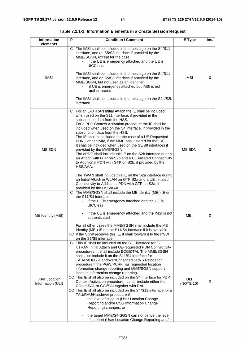
ETSI
ETSI TS 129 274 V12.6.0 (2014-10)343GPP TS 29.274 version 12.6.0 Release 12
Table 7.2.1-1: Information Elements in a Create Session Request
Information elements
P Condition / Comment IE Type Ins.
IMSI
C The IMSI shall be included in the message on the S4/S11 interface, and on S5/S8 interface if provided by the MME/SGSN, except for the case:
- If the UE is emergency attached and the UE is UICCless.
The IMSI shall be included in the message on the S4/S11 interface, and on S5/S8 interface if provided by the MME/SGSN, but not used as an identifier
- if UE is emergency attached but IMSI is not authenticated.
The IMSI shall be included in the message on the S2a/S2b interface.
IMSI 0
MSISDN
C For an E-UTRAN Initial Attach the IE shall be included when used on the S11 interface, if provided in the subscription data from the HSS. For a PDP Context Activation procedure the IE shall be included when used on the S4 interface, if provided in the subscription data from the HSS. The IE shall be included for the case of a UE Requested PDN Connectivity, if the MME has it stored for that UE. It shall be included when used on the S5/S8 interfaces if provided by the MME/SGSN. The ePDG shall include this IE on the S2b interface during an Attach with GTP on S2b and a UE initiated Connectivity to Additional PDN with GTP on S2b, if provided by the HSS/AAA. The TWAN shall include this IE on the S2a interface during an Initial Attach in WLAN on GTP S2a and a UE initiated Connectivity to Additional PDN with GTP on S2a, if provided by the HSS/AAA.
MSISDN 0
ME Identity (MEI)
C The MME/SGSN shall include the ME Identity (MEI) IE on the S11/S4 interface:
- If the UE is emergency attached and the UE is UICCless
- If the UE is emergency attached and the IMSI is not authenticated
For all other cases the MME/SGSN shall include the ME Identity (MEI) IE on the S11/S4 interface if it is available.
MEI 0
CO If the SGW receives this IE, it shall forward it to the PGW on the S5/S8 interface.
User Location Information (ULI)
C This IE shall be included on the S11 interface for E-UTRAN Initial Attach and UE-requested PDN Connectivity procedures. It shall include ECGI&TAI. The MME/SGSN shall also include it on the S11/S4 interface for TAU/RAU/X2-Handover/Enhanced SRNS Relocation procedure if the PGW/PCRF has requested location information change reporting and MME/SGSN support location information change reporting.
ULI (NOTE 10)
0 CO This IE shall also be included on the S4 interface for PDP
Context Activation procedure. It shall include either the CGI or SAI, or CGI/SAI together with RAI.
CO This IE shall also be included on the S4/S11 interface for a TAU/RAU/Handover procedure if
- the level of support (User Location Change Reporting and/or CSG Information Change Reporting) changes; or
- the target MME/S4-SGSN can not derive the level of support (User Location Change Reporting and/or

ETSI
ETSI TS 129 274 V12.6.0 (2014-10)353GPP TS 29.274 version 12.6.0 Release 12
CSG Information Change Reporting) for the source Gn/Gp SGSN. See NOTE 9.
The MME shall include the ECGI and /or TAI in the ULI, the S4-SGSN shall include either the CGI or SAI or RAI, or CGI/SAI together with RAI in the ULI.
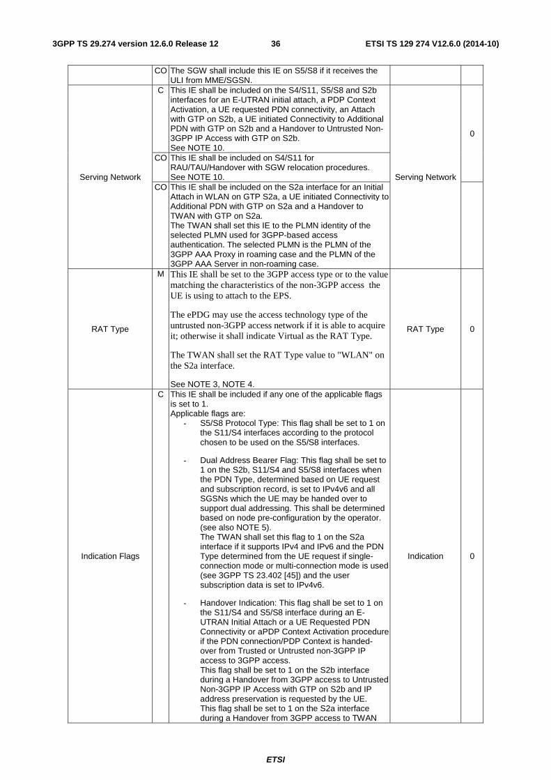
ETSI
ETSI TS 129 274 V12.6.0 (2014-10)363GPP TS 29.274 version 12.6.0 Release 12
CO The SGW shall include this IE on S5/S8 if it receives the ULI from MME/SGSN.
Serving Network
C This IE shall be included on the S4/S11, S5/S8 and S2b interfaces for an E-UTRAN initial attach, a PDP Context Activation, a UE requested PDN connectivity, an Attach with GTP on S2b, a UE initiated Connectivity to Additional PDN with GTP on S2b and a Handover to Untrusted Non-3GPP IP Access with GTP on S2b. See NOTE 10.
Serving Network
0
CO This IE shall be included on S4/S11 for RAU/TAU/Handover with SGW relocation procedures. See NOTE 10.
CO This IE shall be included on the S2a interface for an Initial Attach in WLAN on GTP S2a, a UE initiated Connectivity to Additional PDN with GTP on S2a and a Handover to TWAN with GTP on S2a. The TWAN shall set this IE to the PLMN identity of the selected PLMN used for 3GPP-based access authentication. The selected PLMN is the PLMN of the 3GPP AAA Proxy in roaming case and the PLMN of the 3GPP AAA Server in non-roaming case.
RAT Type
M This IE shall be set to the 3GPP access type or to the value matching the characteristics of the non-3GPP access the UE is using to attach to the EPS.
The ePDG may use the access technology type of the untrusted non-3GPP access network if it is able to acquire it; otherwise it shall indicate Virtual as the RAT Type.
The TWAN shall set the RAT Type value to "WLAN" on the S2a interface.
See NOTE 3, NOTE 4.
RAT Type 0
Indication Flags
C This IE shall be included if any one of the applicable flags is set to 1. Applicable flags are:
- S5/S8 Protocol Type: This flag shall be set to 1 on the S11/S4 interfaces according to the protocol chosen to be used on the S5/S8 interfaces.
- Dual Address Bearer Flag: This flag shall be set to 1 on the S2b, S11/S4 and S5/S8 interfaces when the PDN Type, determined based on UE request and subscription record, is set to IPv4v6 and all SGSNs which the UE may be handed over to support dual addressing. This shall be determined based on node pre-configuration by the operator. (see also NOTE 5). The TWAN shall set this flag to 1 on the S2a interface if it supports IPv4 and IPv6 and the PDN Type determined from the UE request if single-connection mode or multi-connection mode is used (see 3GPP TS 23.402 [45]) and the user subscription data is set to IPv4v6.
- Handover Indication: This flag shall be set to 1 on the S11/S4 and S5/S8 interface during an E-UTRAN Initial Attach or a UE Requested PDN Connectivity or aPDP Context Activation procedure if the PDN connection/PDP Context is handed-over from Trusted or Untrusted non-3GPP IP access to 3GPP access. This flag shall be set to 1 on the S2b interface during a Handover from 3GPP access to Untrusted Non-3GPP IP Access with GTP on S2b and IP address preservation is requested by the UE. This flag shall be set to 1 on the S2a interface during a Handover from 3GPP access to TWAN
Indication 0
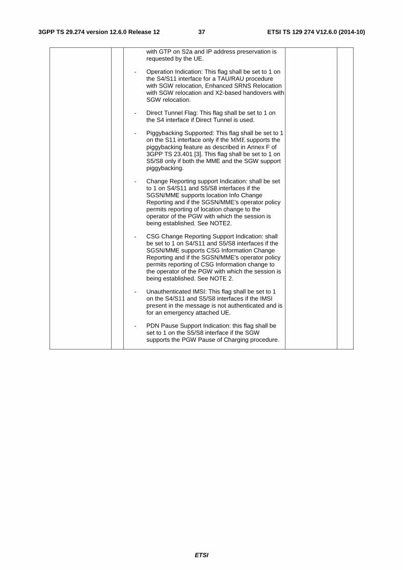
ETSI
ETSI TS 129 274 V12.6.0 (2014-10)373GPP TS 29.274 version 12.6.0 Release 12
with GTP on S2a and IP address preservation is requested by the UE.
- Operation Indication: This flag shall be set to 1 on the S4/S11 interface for a TAU/RAU procedure with SGW relocation, Enhanced SRNS Relocation with SGW relocation and X2-based handovers with SGW relocation.
- Direct Tunnel Flag: This flag shall be set to 1 on the S4 interface if Direct Tunnel is used.
- Piggybacking Supported: This flag shall be set to 1 on the S11 interface only if the MME supports the piggybacking feature as described in Annex F of 3GPP TS 23.401 [3]. This flag shall be set to 1 on S5/S8 only if both the MME and the SGW support piggybacking.
- Change Reporting support Indication: shall be set to 1 on S4/S11 and S5/S8 interfaces if the SGSN/MME supports location Info Change Reporting and if the SGSN/MME's operator policy permits reporting of location change to the operator of the PGW with which the session is being established. See NOTE2.
- CSG Change Reporting Support Indication: shall be set to 1 on S4/S11 and S5/S8 interfaces if the SGSN/MME supports CSG Information Change Reporting and if the SGSN/MME's operator policy permits reporting of CSG Information change to the operator of the PGW with which the session is being established. See NOTE 2.
- Unauthenticated IMSI: This flag shall be set to 1 on the S4/S11 and S5/S8 interfaces if the IMSI present in the message is not authenticated and is for an emergency attached UE.
- PDN Pause Support Indication: this flag shall be set to 1 on the S5/S8 interface if the SGW supports the PGW Pause of Charging procedure.
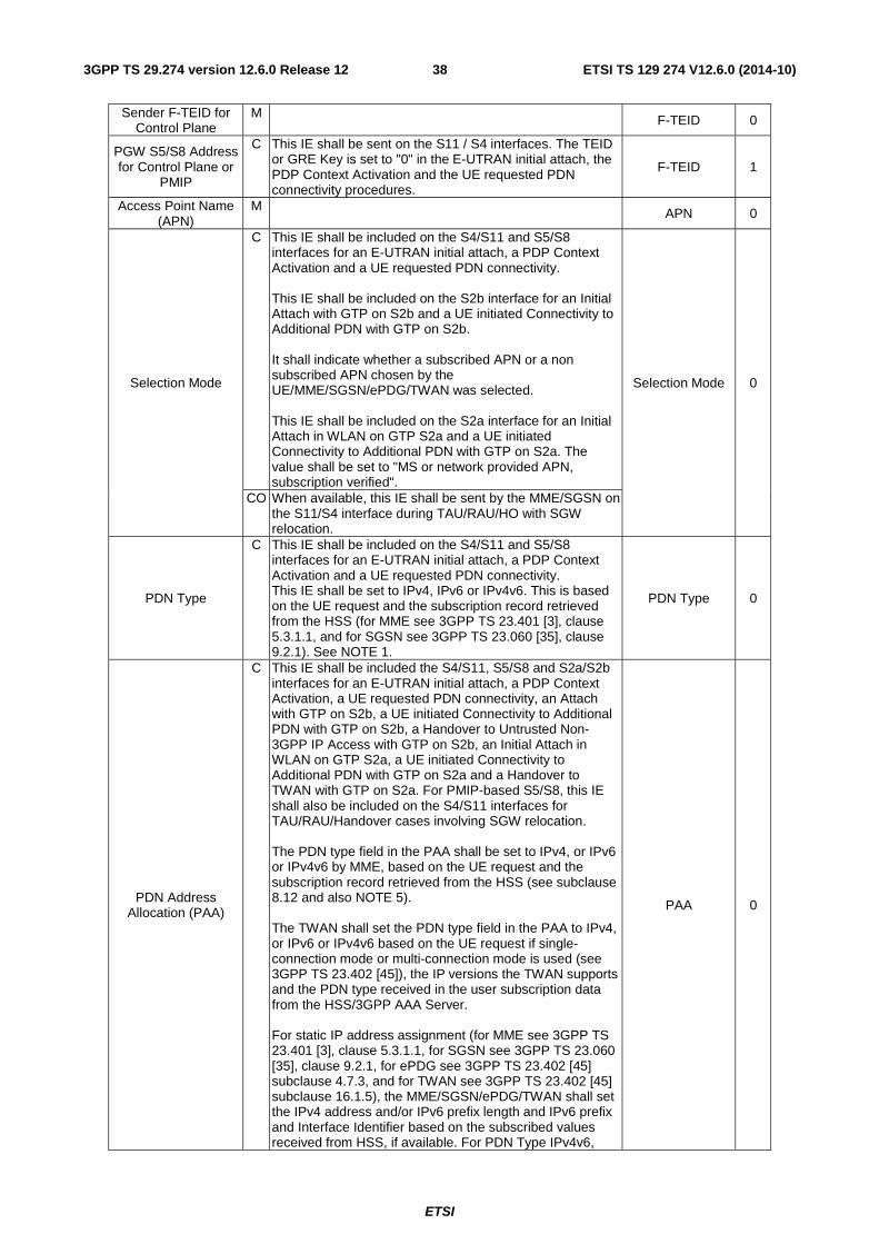
ETSI
ETSI TS 129 274 V12.6.0 (2014-10)383GPP TS 29.274 version 12.6.0 Release 12
Sender F-TEID for Control Plane
M F-TEID 0
PGW S5/S8 Address for Control Plane or
PMIP
C This IE shall be sent on the S11 / S4 interfaces. The TEID or GRE Key is set to "0" in the E-UTRAN initial attach, the PDP Context Activation and the UE requested PDN connectivity procedures.
F-TEID 1
Access Point Name (APN)
M APN 0
Selection Mode
C This IE shall be included on the S4/S11 and S5/S8 interfaces for an E-UTRAN initial attach, a PDP Context Activation and a UE requested PDN connectivity. This IE shall be included on the S2b interface for an Initial Attach with GTP on S2b and a UE initiated Connectivity to Additional PDN with GTP on S2b. It shall indicate whether a subscribed APN or a non subscribed APN chosen by the UE/MME/SGSN/ePDG/TWAN was selected. This IE shall be included on the S2a interface for an Initial Attach in WLAN on GTP S2a and a UE initiated Connectivity to Additional PDN with GTP on S2a. The value shall be set to "MS or network provided APN, subscription verified".
Selection Mode 0
CO When available, this IE shall be sent by the MME/SGSN on the S11/S4 interface during TAU/RAU/HO with SGW relocation.
PDN Type
C This IE shall be included on the S4/S11 and S5/S8 interfaces for an E-UTRAN initial attach, a PDP Context Activation and a UE requested PDN connectivity. This IE shall be set to IPv4, IPv6 or IPv4v6. This is based on the UE request and the subscription record retrieved from the HSS (for MME see 3GPP TS 23.401 [3], clause 5.3.1.1, and for SGSN see 3GPP TS 23.060 [35], clause 9.2.1). See NOTE 1.
PDN Type 0
PDN Address Allocation (PAA)
C This IE shall be included the S4/S11, S5/S8 and S2a/S2b interfaces for an E-UTRAN initial attach, a PDP Context Activation, a UE requested PDN connectivity, an Attach with GTP on S2b, a UE initiated Connectivity to Additional PDN with GTP on S2b, a Handover to Untrusted Non-3GPP IP Access with GTP on S2b, an Initial Attach in WLAN on GTP S2a, a UE initiated Connectivity to Additional PDN with GTP on S2a and a Handover to TWAN with GTP on S2a. For PMIP-based S5/S8, this IE shall also be included on the S4/S11 interfaces for TAU/RAU/Handover cases involving SGW relocation. The PDN type field in the PAA shall be set to IPv4, or IPv6 or IPv4v6 by MME, based on the UE request and the subscription record retrieved from the HSS (see subclause 8.12 and also NOTE 5). The TWAN shall set the PDN type field in the PAA to IPv4, or IPv6 or IPv4v6 based on the UE request if single-connection mode or multi-connection mode is used (see 3GPP TS 23.402 [45]), the IP versions the TWAN supports and the PDN type received in the user subscription data from the HSS/3GPP AAA Server. For static IP address assignment (for MME see 3GPP TS 23.401 [3], clause 5.3.1.1, for SGSN see 3GPP TS 23.060 [35], clause 9.2.1, for ePDG see 3GPP TS 23.402 [45] subclause 4.7.3, and for TWAN see 3GPP TS 23.402 [45] subclause 16.1.5), the MME/SGSN/ePDG/TWAN shall set the IPv4 address and/or IPv6 prefix length and IPv6 prefix and Interface Identifier based on the subscribed values received from HSS, if available. For PDN Type IPv4v6,
PAA 0
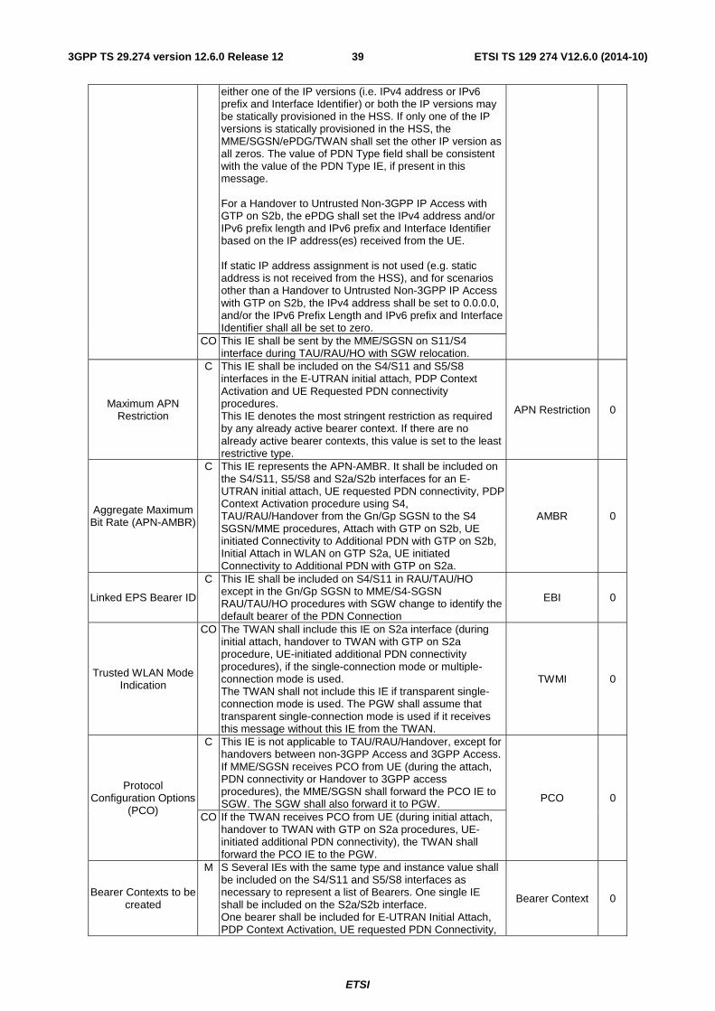
ETSI
ETSI TS 129 274 V12.6.0 (2014-10)393GPP TS 29.274 version 12.6.0 Release 12
either one of the IP versions (i.e. IPv4 address or IPv6 prefix and Interface Identifier) or both the IP versions may be statically provisioned in the HSS. If only one of the IP versions is statically provisioned in the HSS, the MME/SGSN/ePDG/TWAN shall set the other IP version as all zeros. The value of PDN Type field shall be consistent with the value of the PDN Type IE, if present in this message. For a Handover to Untrusted Non-3GPP IP Access with GTP on S2b, the ePDG shall set the IPv4 address and/or IPv6 prefix length and IPv6 prefix and Interface Identifier based on the IP address(es) received from the UE. If static IP address assignment is not used (e.g. static address is not received from the HSS), and for scenarios other than a Handover to Untrusted Non-3GPP IP Access with GTP on S2b, the IPv4 address shall be set to 0.0.0.0, and/or the IPv6 Prefix Length and IPv6 prefix and Interface Identifier shall all be set to zero.
CO This IE shall be sent by the MME/SGSN on S11/S4 interface during TAU/RAU/HO with SGW relocation.
Maximum APN Restriction
C This IE shall be included on the S4/S11 and S5/S8 interfaces in the E-UTRAN initial attach, PDP Context Activation and UE Requested PDN connectivity procedures. This IE denotes the most stringent restriction as required by any already active bearer context. If there are no already active bearer contexts, this value is set to the least restrictive type.
APN Restriction 0
Aggregate Maximum Bit Rate (APN-AMBR)
C This IE represents the APN-AMBR. It shall be included on the S4/S11, S5/S8 and S2a/S2b interfaces for an E-UTRAN initial attach, UE requested PDN connectivity, PDP Context Activation procedure using S4, TAU/RAU/Handover from the Gn/Gp SGSN to the S4 SGSN/MME procedures, Attach with GTP on S2b, UE initiated Connectivity to Additional PDN with GTP on S2b, Initial Attach in WLAN on GTP S2a, UE initiated Connectivity to Additional PDN with GTP on S2a.
AMBR 0
Linked EPS Bearer ID
C This IE shall be included on S4/S11 in RAU/TAU/HO except in the Gn/Gp SGSN to MME/S4-SGSN RAU/TAU/HO procedures with SGW change to identify the default bearer of the PDN Connection
EBI 0
Trusted WLAN Mode Indication
CO
The TWAN shall include this IE on S2a interface (during initial attach, handover to TWAN with GTP on S2a procedure, UE-initiated additional PDN connectivity procedures), if the single-connection mode or multiple-connection mode is used. The TWAN shall not include this IE if transparent single-connection mode is used. The PGW shall assume that transparent single-connection mode is used if it receives this message without this IE from the TWAN.
TWMI 0
Protocol Configuration Options
(PCO)
C This IE is not applicable to TAU/RAU/Handover, except for handovers between non-3GPP Access and 3GPP Access. If MME/SGSN receives PCO from UE (during the attach, PDN connectivity or Handover to 3GPP access procedures), the MME/SGSN shall forward the PCO IE to SGW. The SGW shall also forward it to PGW. PCO 0
CO If the TWAN receives PCO from UE (during initial attach, handover to TWAN with GTP on S2a procedures, UE-initiated additional PDN connectivity), the TWAN shall forward the PCO IE to the PGW.
Bearer Contexts to be created
M S Several IEs with the same type and instance value shall be included on the S4/S11 and S5/S8 interfaces as necessary to represent a list of Bearers. One single IE shall be included on the S2a/S2b interface. One bearer shall be included for E-UTRAN Initial Attach, PDP Context Activation, UE requested PDN Connectivity,
Bearer Context 0
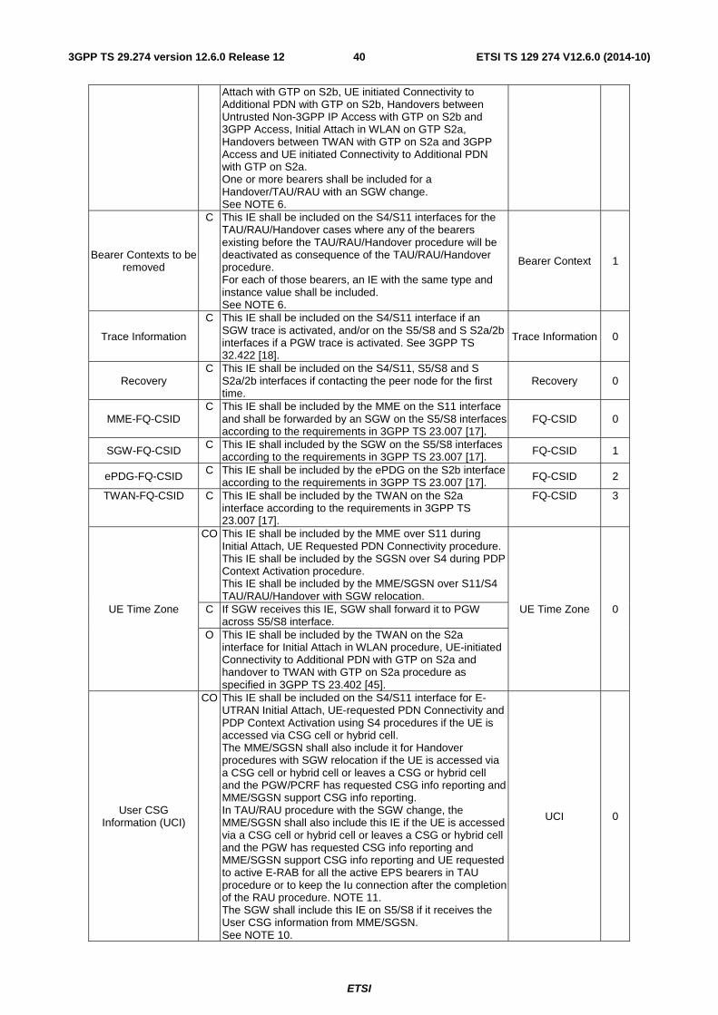
ETSI
ETSI TS 129 274 V12.6.0 (2014-10)403GPP TS 29.274 version 12.6.0 Release 12
Attach with GTP on S2b, UE initiated Connectivity to Additional PDN with GTP on S2b, Handovers between Untrusted Non-3GPP IP Access with GTP on S2b and 3GPP Access, Initial Attach in WLAN on GTP S2a, Handovers between TWAN with GTP on S2a and 3GPP Access and UE initiated Connectivity to Additional PDN with GTP on S2a. One or more bearers shall be included for a Handover/TAU/RAU with an SGW change. See NOTE 6.
Bearer Contexts to be removed
C This IE shall be included on the S4/S11 interfaces for the TAU/RAU/Handover cases where any of the bearers existing before the TAU/RAU/Handover procedure will be deactivated as consequence of the TAU/RAU/Handover procedure. For each of those bearers, an IE with the same type and instance value shall be included. See NOTE 6.
Bearer Context 1
Trace Information
C This IE shall be included on the S4/S11 interface if an SGW trace is activated, and/or on the S5/S8 and S S2a/2b interfaces if a PGW trace is activated. See 3GPP TS 32.422 [18].
Trace Information 0
Recovery C This IE shall be included on the S4/S11, S5/S8 and S
S2a/2b interfaces if contacting the peer node for the first time.
Recovery 0
MME-FQ-CSID C This IE shall be included by the MME on the S11 interface
and shall be forwarded by an SGW on the S5/S8 interfaces according to the requirements in 3GPP TS 23.007 [17].
FQ-CSID 0
SGW-FQ-CSID C This IE shall included by the SGW on the S5/S8 interfaces according to the requirements in 3GPP TS 23.007 [17]. FQ-CSID 1
ePDG-FQ-CSID C This IE shall be included by the ePDG on the S2b interface according to the requirements in 3GPP TS 23.007 [17]. FQ-CSID 2
TWAN-FQ-CSID C This IE shall be included by the TWAN on the S2a interface according to the requirements in 3GPP TS 23.007 [17].
FQ-CSID 3
UE Time Zone
CO This IE shall be included by the MME over S11 during Initial Attach, UE Requested PDN Connectivity procedure. This IE shall be included by the SGSN over S4 during PDP Context Activation procedure. This IE shall be included by the MME/SGSN over S11/S4 TAU/RAU/Handover with SGW relocation.
UE Time Zone 0 C If SGW receives this IE, SGW shall forward it to PGW across S5/S8 interface.
O This IE shall be included by the TWAN on the S2a interface for Initial Attach in WLAN procedure, UE-initiated Connectivity to Additional PDN with GTP on S2a and handover to TWAN with GTP on S2a procedure as specified in 3GPP TS 23.402 [45].
User CSG Information (UCI)
CO This IE shall be included on the S4/S11 interface for E-UTRAN Initial Attach, UE-requested PDN Connectivity and PDP Context Activation using S4 procedures if the UE is accessed via CSG cell or hybrid cell. The MME/SGSN shall also include it for Handover procedures with SGW relocation if the UE is accessed via a CSG cell or hybrid cell or leaves a CSG or hybrid cell and the PGW/PCRF has requested CSG info reporting and MME/SGSN support CSG info reporting. In TAU/RAU procedure with the SGW change, the MME/SGSN shall also include this IE if the UE is accessed via a CSG cell or hybrid cell or leaves a CSG or hybrid cell and the PGW has requested CSG info reporting and MME/SGSN support CSG info reporting and UE requested to active E-RAB for all the active EPS bearers in TAU procedure or to keep the Iu connection after the completion of the RAU procedure. NOTE 11. The SGW shall include this IE on S5/S8 if it receives the User CSG information from MME/SGSN. See NOTE 10.
UCI 0
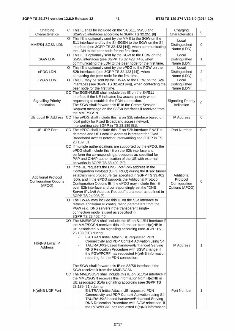
ETSI
ETSI TS 129 274 V12.6.0 (2014-10)413GPP TS 29.274 version 12.6.0 Release 12
Charging Characteristics
C This IE shall be included on the S4/S11, S5/S8 and S2a/S2b interfaces according to 3GPP TS 32.251 [8]
Charging Characteristics 0
MME/S4-SGSN LDN
O This IE is optionally sent by the MME to the SGW on the S11 interface and by the S4-SGSN to the SGW on the S4 interface (see 3GPP TS 32.423 [44]), when communicating the LDN to the peer node for the first time.
Local Distinguished Name (LDN)
0
SGW LDN O This IE is optionally sent by the SGW to the PGW on the
S5/S8 interfaces (see 3GPP TS 32.423 [44]), when communicating the LDN to the peer node for the first time.
Local Distinguished Name (LDN)
1
ePDG LDN O This IE is optionally sent by the ePDG to the PGW on the
S2b interfaces (see 3GPP TS 32.423 [44]), when contacting the peer node for the first time.
Local Distinguished Name (LDN)
2
TWAN LDN O This IE may be sent by the TWAN to the PGW on the S2a interfaces (see 3GPP TS 32.423 [44]), when contacting the peer node for the first time.
Local Distinguished Name (LDN)
3
Signalling Priority Indication
CO The SGSN/MME shall include this IE on the S4/S11 interface if the UE indicates low access priority when requesting to establish the PDN connection. The SGW shall forward this IE in the Create Session Request message on the S5/S8 interfaces if received from the MME/SGSN.
Signalling Priority Indication 0
UE Local IP Address CO The ePDG shall include this IE on S2b interface based on local policy for Fixed Broadband access network interworking see 3GPP in TS 23.139 [51].
IP Address 0
UE UDP Port CO The ePDG shall include this IE on S2b interface if NAT is detected and UE Local IP Address is present for Fixed Broadband access network interworking see 3GPP in TS 23.139 [51].
Port Number 0
Additional Protocol Configuration Options
(APCO)
CO If multiple authentications are supported by the ePDG, the ePDG shall include this IE on the S2b interface and perform the corresponding procedures as specified for PAP and CHAP authentication of the UE with external networks in 3GPP TS 33.402 [50].
Additional Protocol
Configuration Options (APCO)
0
O If the UE requests the DNS IPv4/IPv6 address in the Configuration Payload (CFG_REQ) during the IPsec tunnel establishment procedure (as specified in 3GPP TS 33.402 [50]), and if the ePDG supports the Additional Protocol Configuration Options IE, the ePDG may include this IE over S2b interface and correspondingly set the "DNS Server IPv4/v6 Address Request" parameter as defined in 3GPP TS 24.008 [5].
O The TWAN may include this IE on the S2a interface to retrieve additional IP configuration parameters from the PGW (e.g. DNS server) if the transparent single-connection mode is used as specified in 3GPP TS 23.402 [45].
H(e)NB Local IP Address
CO The MME/SGSN shall include this IE on S11/S4 interface if the MME/SGSN receives this information from H(e)NB in UE associated S1/Iu signalling according (see 3GPP TS 23.139 [51]) during:
- E-UTRAN Initial Attach, UE-requested PDN Connectivity and PDP Context Activation using S4;
- TAU/RAU/X2-based handover/Enhanced Serving RNS Relocation Procedure with SGW change, if the PGW/PCRF has requested H(e)NB information reporting for the PDN connection.
The SGW shall forward this IE on S5/S8 interface if the SGW receives it from the MME/SGSN.
IP Address 1
H(e)NB UDP Port
CO The MME/SGSN shall include this IE on S11/S4 interface if the MME/SGSN receives this information from H(e)NB in UE associated S1/Iu signalling according (see 3GPP TS 23.139 [51]) during:
- E-UTRAN Initial Attach, UE-requested PDN Connectivity and PDP Context Activation using S4;
- TAU/RAU/X2-based handover/Enhanced Serving RNS Relocation Procedure with SGW relocation, if the PGW/PCRF has requested H(e)NB information
Port Number 1
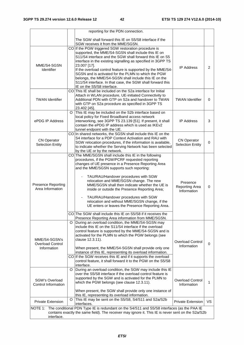
ETSI
ETSI TS 129 274 V12.6.0 (2014-10)423GPP TS 29.274 version 12.6.0 Release 12
reporting for the PDN connection. The SGW shall forward this IE on S5/S8 interface if the SGW receives it from the MME/SGSN.
MME/S4-SGSN Identifier
CO If the PGW triggered SGW restoration procedure is supported, the MME/S4-SGSN shall include this IE on S11/S4 interface and the SGW shall forward this IE on S5 interface in the existing signalling as specified in 3GPP TS 23.007 [17]. If the overload control feature is supported by the MME/S4-SGSN and is activated for the PLMN to which the PGW belongs, the MME/S4-SGSN shall include this IE on the S11/S4 interface. In that case, the SGW shall forward this IE on the S5/S8 interface.
IP Address 2
TWAN Identifier
CO This IE shall be included on the S2a interface for Initial Attach in WLAN procedure, UE-initiated Connectivity to Additional PDN with GTP on S2a and handover to TWAN with GTP on S2a procedure as specified in 3GPP TS 23.402 [45].
TWAN Identifier 0
ePDG IP Address
O This IE may be included on the S2b interface based on local policy for Fixed Broadband access network interworking, see 3GPP TS 23.139 [51]. If present, it shall contain the ePDG IP address which is used as IKEv2 tunnel endpoint with the UE.
IP Address 3
CN Operator Selection Entity
CO In shared networks, the SGSN shall include this IE on the S4 interface for a PDP Context Activation and RAU with SGW relocation procedures, if the information is available, to indicate whether the Serving Network has been selected by the UE or by the network.
CN Operator Selection Entity 0
Presence Reporting Area Information
CO The MME/SGSN shall include this IE in the following procedures, if the PGW/PCRF requested reporting changes of UE presence in a Presence Reporting Area and the MME/SGSN supports such reporting:
- TAU/RAU/Handover procedures with SGW relocation and MME/SGSN change. The new MME/SGSN shall then indicate whether the UE is inside or outside the Presence Reporting Area;
- TAU/RAU/Handover procedures with SGW relocation and without MME/SGSN change, if the UE enters or leaves the Presence Reporting Area.
Presence Reporting Area
Information 0
CO The SGW shall include this IE on S5/S8 if it receives the Presence Reporting Area information from MME/SGSN.
MME/S4-SGSN's Overload Control
Information
O During an overload condition, the MME/S4-SGSN may include this IE on the S11/S4 interface if the overload control feature is supported by the MME/S4-SGSN and is activated for the PLMN to which the PGW belongs (see clause 12.3.11). When present, the MME/S4-SGSN shall provide only one instance of this IE, representing its overload information.
Overload Control Information
0
CO If the SGW receives this IE and if it supports the overload control feature, it shall forward it to the PGW on the S5/S8 interface.
SGW's Overload Control Information
O During an overload condition, the SGW may include this IE over the S5/S8 interface if the overload control feature is supported by the SGW and is activated for the PLMN to which the PGW belongs (see clause 12.3.11). When present, the SGW shall provide only one instance of this IE, representing its overload information.
Overload Control Information 1
Private Extension O This IE may be sent on the S5/S8, S4/S11 and S2a/S2b interfaces. Private Extension VS
NOTE 1: The conditional PDN Type IE is redundant on the S4/S11 and S5/S8 interfaces (as the PAA IE contains exactly the same field). The receiver may ignore it. This IE is never sent on the S2a/S2b interface.
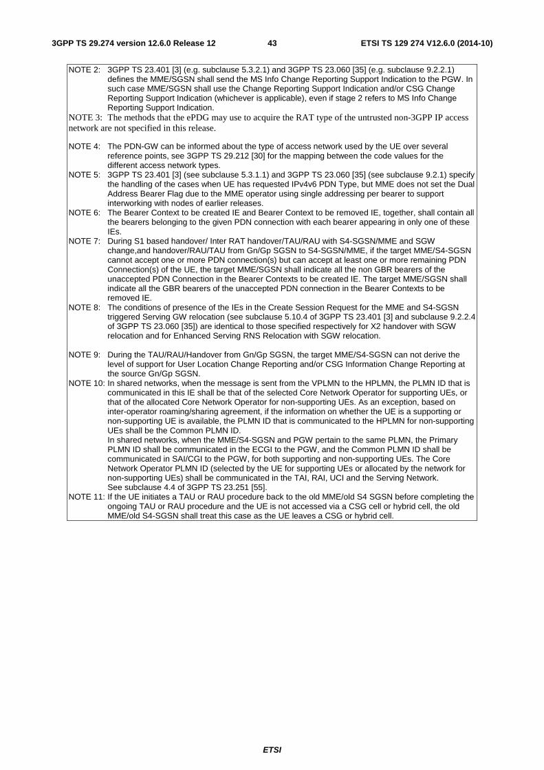
ETSI
ETSI TS 129 274 V12.6.0 (2014-10)433GPP TS 29.274 version 12.6.0 Release 12
NOTE 2: 3GPP TS 23.401 [3] (e.g. subclause 5.3.2.1) and 3GPP TS 23.060 [35] (e.g. subclause 9.2.2.1) defines the MME/SGSN shall send the MS Info Change Reporting Support Indication to the PGW. In such case MME/SGSN shall use the Change Reporting Support Indication and/or CSG Change Reporting Support Indication (whichever is applicable), even if stage 2 refers to MS Info Change Reporting Support Indication.
NOTE 3: The methods that the ePDG may use to acquire the RAT type of the untrusted non-3GPP IP access network are not specified in this release.
NOTE 4: The PDN-GW can be informed about the type of access network used by the UE over several reference points, see 3GPP TS 29.212 [30] for the mapping between the code values for the different access network types.
NOTE 5: 3GPP TS 23.401 [3] (see subclause 5.3.1.1) and 3GPP TS 23.060 [35] (see subclause 9.2.1) specify the handling of the cases when UE has requested IPv4v6 PDN Type, but MME does not set the Dual Address Bearer Flag due to the MME operator using single addressing per bearer to support interworking with nodes of earlier releases.
NOTE 6: The Bearer Context to be created IE and Bearer Context to be removed IE, together, shall contain all the bearers belonging to the given PDN connection with each bearer appearing in only one of these IEs.
NOTE 7: During S1 based handover/ Inter RAT handover/TAU/RAU with S4-SGSN/MME and SGW change,and handover/RAU/TAU from Gn/Gp SGSN to S4-SGSN/MME, if the target MME/S4-SGSN cannot accept one or more PDN connection(s) but can accept at least one or more remaining PDN Connection(s) of the UE, the target MME/SGSN shall indicate all the non GBR bearers of the unaccepted PDN Connection in the Bearer Contexts to be created IE. The target MME/SGSN shall indicate all the GBR bearers of the unaccepted PDN connection in the Bearer Contexts to be removed IE.
NOTE 8: The conditions of presence of the IEs in the Create Session Request for the MME and S4-SGSN triggered Serving GW relocation (see subclause 5.10.4 of 3GPP TS 23.401 [3] and subclause 9.2.2.4 of 3GPP TS 23.060 [35]) are identical to those specified respectively for X2 handover with SGW relocation and for Enhanced Serving RNS Relocation with SGW relocation.
NOTE 9: During the TAU/RAU/Handover from Gn/Gp SGSN, the target MME/S4-SGSN can not derive the
level of support for User Location Change Reporting and/or CSG Information Change Reporting at the source Gn/Gp SGSN.
NOTE 10: In shared networks, when the message is sent from the VPLMN to the HPLMN, the PLMN ID that is communicated in this IE shall be that of the selected Core Network Operator for supporting UEs, or that of the allocated Core Network Operator for non-supporting UEs. As an exception, based on inter-operator roaming/sharing agreement, if the information on whether the UE is a supporting or non-supporting UE is available, the PLMN ID that is communicated to the HPLMN for non-supporting UEs shall be the Common PLMN ID. In shared networks, when the MME/S4-SGSN and PGW pertain to the same PLMN, the Primary PLMN ID shall be communicated in the ECGI to the PGW, and the Common PLMN ID shall be communicated in SAI/CGI to the PGW, for both supporting and non-supporting UEs. The Core Network Operator PLMN ID (selected by the UE for supporting UEs or allocated by the network for non-supporting UEs) shall be communicated in the TAI, RAI, UCI and the Serving Network. See subclause 4.4 of 3GPP TS 23.251 [55].
NOTE 11: If the UE initiates a TAU or RAU procedure back to the old MME/old S4 SGSN before completing the ongoing TAU or RAU procedure and the UE is not accessed via a CSG cell or hybrid cell, the old MME/old S4-SGSN shall treat this case as the UE leaves a CSG or hybrid cell.
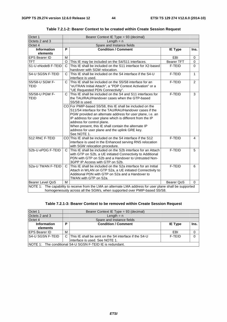
ETSI
ETSI TS 129 274 V12.6.0 (2014-10)443GPP TS 29.274 version 12.6.0 Release 12
Table 7.2.1-2: Bearer Context to be created within Create Session Request
Octet 1 Bearer Context IE Type = 93 (decimal) Octets 2 and 3 Length = n Octet 4 Spare and Instance fields
Information elements
P Condition / Comment IE Type Ins.
EPS Bearer ID M EBI 0 TFT O This IE may be included on the S4/S11 interfaces. Bearer TFT 0 S1-U eNodeB F-TEID C This IE shall be included on the S11 interface for X2-based
handover with SGW relocation. F-TEID 0
S4-U SGSN F-TEID C This IE shall be included on the S4 interface if the S4-U interface is used.
F-TEID 1
S5/S8-U SGW F-TEID
C This IE shall be included on the S5/S8 interface for an "eUTRAN Initial Attach", a "PDP Context Activation" or a "UE Requested PDN Connectivity".
F-TEID 2
S5/S8-U PGW F-TEID
C This IE shall be included on the S4 and S11 interfaces for the TAU/RAU/Handover cases when the GTP-based S5/S8 is used.
F-TEID 3
CO For PMIP-based S5/S8, this IE shall be included on the S11/S4 interface for the TAU/RAU/Handover cases if the PGW provided an alternate address for user plane, i.e. an IP address for user plane which is different from the IP address for control plane. When present, this IE shall contain the alternate IP address for user plane and the uplink GRE key. See NOTE 1.
S12 RNC F-TEID CO This IE shall be included on the S4 interface if the S12 interface is used in the Enhanced serving RNS relocation with SGW relocation procedure.
F-TEID 4
S2b-U ePDG F-TEID C This IE shall be included on the S2b interface for an Attach with GTP on S2b, a UE initiated Connectivity to Additional PDN with GTP on S2b and a Handover to Untrusted Non-3GPP IP Access with GTP on S2b.
F-TEID 5
S2a-U TWAN F-TEID C This IE shall be included on the S2a interface for an Initial Attach in WLAN on GTP S2a, a UE initiated Connectivity to Additional PDN with GTP on S2a and a Handover to TWAN with GTP on S2a.
F-TEID 6
Bearer Level QoS M Bearer QoS 0 NOTE 1: The capability to receive from the LMA an alternate LMA address for user plane shall be supported
homogeneously across all the SGWs, when supported over PMIP-based S5/S8.
Table 7.2.1-3: Bearer Context to be removed within Create Session Request
Octet 1 Bearer Context IE Type = 93 (decimal) Octets 2 and 3 Length = n Octet 4 Spare and Instance fields
Information elements
P Condition / Comment IE Type Ins.
EPS Bearer ID M EBI 0 S4-U SGSN F-TEID C This IE shall be sent on the S4 interface if the S4-U
interface is used. See NOTE 1. F-TEID 0
NOTE 1: The conditional S4-U SGSN F-TEID IE is redundant.
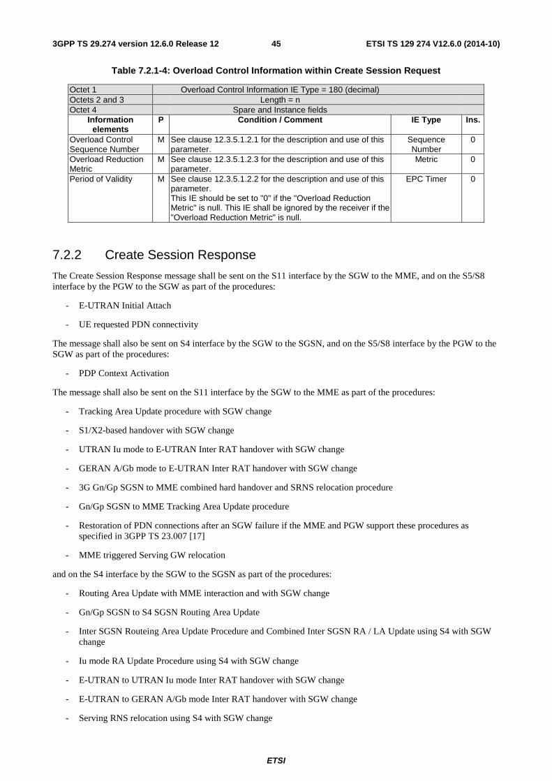
ETSI
ETSI TS 129 274 V12.6.0 (2014-10)453GPP TS 29.274 version 12.6.0 Release 12
Table 7.2.1-4: Overload Control Information within Create Session Request
Octet 1 Overload Control Information IE Type = 180 (decimal) Octets 2 and 3 Length = n Octet 4 Spare and Instance fields
Information elements
P Condition / Comment IE Type Ins.
Overload Control Sequence Number
M See clause 12.3.5.1.2.1 for the description and use of this parameter.
Sequence Number
0
Overload Reduction Metric
M See clause 12.3.5.1.2.3 for the description and use of this parameter.
Metric 0
Period of Validity M See clause 12.3.5.1.2.2 for the description and use of this parameter. This IE should be set to "0" if the "Overload Reduction Metric" is null. This IE shall be ignored by the receiver if the "Overload Reduction Metric" is null.
EPC Timer 0
7.2.2 Create Session Response
The Create Session Response message shall be sent on the S11 interface by the SGW to the MME, and on the S5/S8 interface by the PGW to the SGW as part of the procedures:
- E-UTRAN Initial Attach
- UE requested PDN connectivity
The message shall also be sent on S4 interface by the SGW to the SGSN, and on the S5/S8 interface by the PGW to the SGW as part of the procedures:
- PDP Context Activation
The message shall also be sent on the S11 interface by the SGW to the MME as part of the procedures:
- Tracking Area Update procedure with SGW change
- S1/X2-based handover with SGW change
- UTRAN Iu mode to E-UTRAN Inter RAT handover with SGW change
- GERAN A/Gb mode to E-UTRAN Inter RAT handover with SGW change
- 3G Gn/Gp SGSN to MME combined hard handover and SRNS relocation procedure
- Gn/Gp SGSN to MME Tracking Area Update procedure
- Restoration of PDN connections after an SGW failure if the MME and PGW support these procedures as specified in 3GPP TS 23.007 [17]
- MME triggered Serving GW relocation
and on the S4 interface by the SGW to the SGSN as part of the procedures:
- Routing Area Update with MME interaction and with SGW change
- Gn/Gp SGSN to S4 SGSN Routing Area Update
- Inter SGSN Routeing Area Update Procedure and Combined Inter SGSN RA / LA Update using S4 with SGW change
- Iu mode RA Update Procedure using S4 with SGW change
- E-UTRAN to UTRAN Iu mode Inter RAT handover with SGW change
- E-UTRAN to GERAN A/Gb mode Inter RAT handover with SGW change
- Serving RNS relocation using S4 with SGW change
ETSI
ETSI TS 129 274 V12.6.0 (2014-10)463GPP TS 29.274 version 12.6.0 Release 12
- Combined hard handover and SRNS relocation using S4 with SGW change
- Combined Cell / URA update and SRNS relocation using S4 with SGW change
- Enhanced serving RNS relocation with SGW relocation
- Restoration of PDN connections after an SGW failure if the SGSN and PGW support these procedures as specified in 3GPP TS 23.007 [17]
- S4-SGSN triggered Serving GW relocation
and on the S2b interface by the PGW to the ePDG as part of the procedures:
- Initial Attach with GTP on S2b
- UE initiated Connectivity to Additional PDN with GTP on S2b
- Handover to Untrusted Non-3GPP IP Access with GTP on S2b
and on the S2a interface by the PGW to the TWAN as part of the procedure:
- Initial Attach in WLAN on GTP S2a
- UE initiated Connectivity to Additional PDN with GTP on S2a
- Handover to TWAN with GTP on S2a
If handling of default bearer fails, then cause at the message level shall be a failure cause.
Possible Cause values are specified in Table 8.4-1. Message specific cause values are:
- "Request accepted".
- "Request accepted partially".
- "New PDN type due to network preference".
- "New PDN type due to single address bearer only".
- "Missing or unknown APN".
- "GRE key not found".
- "Preferred PDN type not supported".
- "All dynamic addresses are occupied".
- "Remote peer not responding".
- "Semantic error in the TFT operation".
- "Syntactic error in the TFT operation".
- "Semantic errors in packet filter(s)".
- "Syntactic errors in packet filter(s)".
- "User authentication failed".
- "APN access denied – no subscription".
- "APN Restriction type incompatibility with currently active PDN Connection".
- "Version not supported by next peer".
- "Denied in RAT".
- "Protocol type not supported".

ETSI
ETSI TS 129 274 V12.6.0 (2014-10)473GPP TS 29.274 version 12.6.0 Release 12
- "APN congestion".
- "Multiple PDN connections for a given APN not allowed".
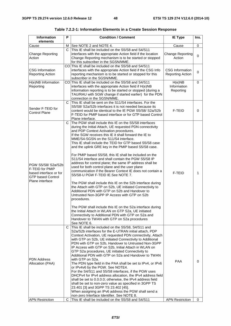
ETSI
ETSI TS 129 274 V12.6.0 (2014-10)483GPP TS 29.274 version 12.6.0 Release 12
Table 7.2.2-1: Information Elements in a Create Session Response
Information elements
P Condition / Comment IE Type Ins.
Cause M See NOTE 2 and NOTE 4. Cause 0
Change Reporting Action
C This IE shall be included on the S5/S8 and S4/S11 interfaces with the appropriate Action field if the location Change Reporting mechanism is to be started or stopped for this subscriber in the SGSN/MME.
Change Reporting Action 0
CSG Information Reporting Action
CO This IE shall be included on the S5/S8 and S4/S11 interfaces with the appropriate Action field if the CSG Info reporting mechanism is to be started or stopped for this subscriber in the SGSN/MME.
CSG Information Reporting Action 0
H(e)NB Information Reporting
CO This IE shall be included on the S5/S8 and S4/S11 interfaces with the appropriate Action field if H(e)NB information reporting is to be started or stopped (during a TAU/RAU with SGW change if started earlier) for the PDN connection in the SGSN/MME.
H(e)NB Information Reporting
0
Sender F-TEID for Control Plane
C This IE shall be sent on the S11/S4 interfaces. For the S5/S8/ S2a/S2b interfaces it is not needed because its content would be identical to the IE PGW S5/S8/ S2a/S2b F-TEID for PMIP based interface or for GTP based Control Plane interface.
F-TEID 0
PGW S5/S8/ S2a/S2b F-TEID for PMIP based interface or for GTP based Control Plane interface
C The PGW shall include this IE on the S5/S8 interfaces during the Initial Attach, UE requested PDN connectivity and PDP Context Activation procedures. If the SGW receives this IE it shall forward the IE to MME/S4-SGSN on the S11/S4 interface. This IE shall include the TEID for GTP based S5/S8 case and the uplink GRE key in the PMIP based S5/S8 case. For PMIP based S5/S8, this IE shall be included on the S11/S4 interface and shall contain the PGW S5/S8 IP address for control plane; the same IP address shall be used for both control plane and the user plane communication if the Bearer Context IE does not contain a S5/S8-U PGW F-TEID IE.See NOTE 7. The PGW shall include this IE on the S2b interface during the Attach with GTP on S2b, UE initiated Connectivity to Additional PDN with GTP on S2b and Handover to Untrusted Non-3GPP IP Access with GTP on S2b procedures. The PGW shall include this IE on the S2a interface during the Initial Attach in WLAN on GTP S2a, UE initiated Connectivity to Additional PDN with GTP on S2a and Handover to TWAN with GTP on S2a procedures See NOTE 6.
F-TEID 1
PDN Address Allocation (PAA)
C This IE shall be included on the S5/S8, S4/S11 and S2a/S2b interfaces for the E-UTRAN initial attach, PDP Context Activation, UE requested PDN connectivity, Attach with GTP on S2b, UE initiated Connectivity to Additional PDN with GTP on S2b, Handover to Untrusted Non-3GPP IP Access with GTP on S2b, Initial Attach in WLAN on GTP S2a procedures, UE initiated Connectivity to Additional PDN with GTP on S2a and Handover to TWAN with GTP on S2a. The PDN type field in the PAA shall be set to IPv4, or IPv6 or IPv4v6 by the PGW. See NOTE4. For the S4/S11 and S5/S8 interfaces, if the PGW uses DHCPv4 for IPv4 address allocation, the IPv4 address field shall be set to 0.0.0.0; otherwise, the IPv4 address field shall be set to non-zero value as specified in 3GPP TS 23.401 [3] and 3GPP TS 23.402 [45]. When assigning an IPv6 address the PGW shall send a non-zero Interface Identifier. See NOTE 8.
PAA 0
APN Restriction C This IE shall be included on the S5/S8 and S4/S11 APN Restriction 0
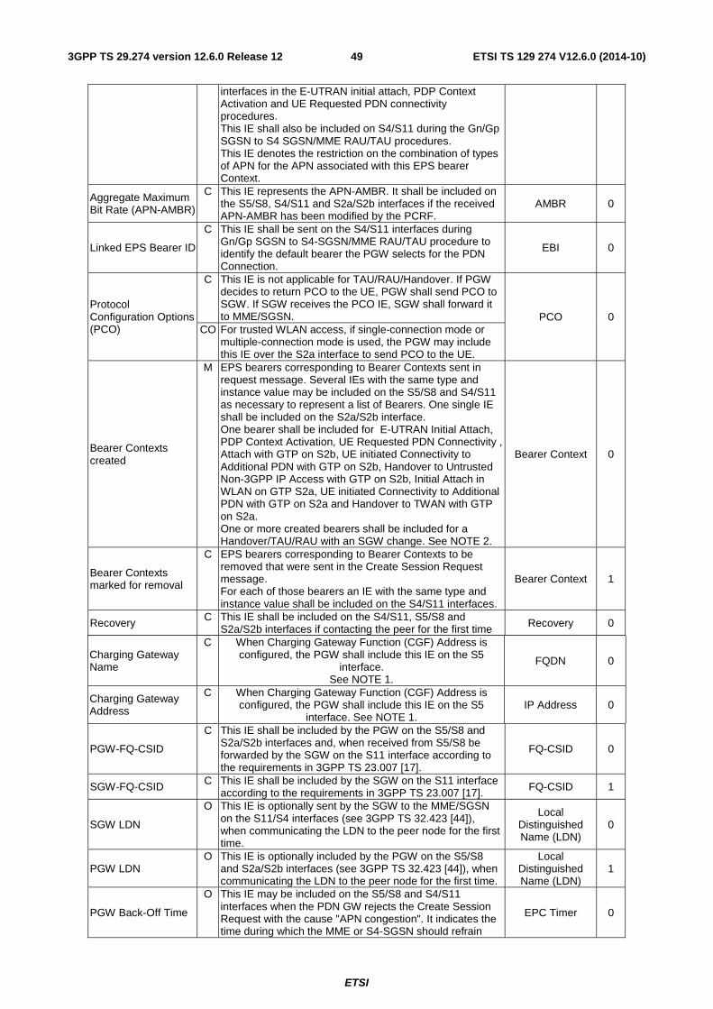
ETSI
ETSI TS 129 274 V12.6.0 (2014-10)493GPP TS 29.274 version 12.6.0 Release 12
interfaces in the E-UTRAN initial attach, PDP Context Activation and UE Requested PDN connectivity procedures. This IE shall also be included on S4/S11 during the Gn/Gp SGSN to S4 SGSN/MME RAU/TAU procedures. This IE denotes the restriction on the combination of types of APN for the APN associated with this EPS bearer Context.
Aggregate Maximum Bit Rate (APN-AMBR)
C This IE represents the APN-AMBR. It shall be included on the S5/S8, S4/S11 and S2a/S2b interfaces if the received APN-AMBR has been modified by the PCRF.
AMBR 0
Linked EPS Bearer ID
C This IE shall be sent on the S4/S11 interfaces during Gn/Gp SGSN to S4-SGSN/MME RAU/TAU procedure to identify the default bearer the PGW selects for the PDN Connection.
EBI 0
Protocol Configuration Options (PCO)
C This IE is not applicable for TAU/RAU/Handover. If PGW decides to return PCO to the UE, PGW shall send PCO to SGW. If SGW receives the PCO IE, SGW shall forward it to MME/SGSN. PCO 0
CO For trusted WLAN access, if single-connection mode or multiple-connection mode is used, the PGW may include this IE over the S2a interface to send PCO to the UE.
Bearer Contexts created
M EPS bearers corresponding to Bearer Contexts sent in request message. Several IEs with the same type and instance value may be included on the S5/S8 and S4/S11 as necessary to represent a list of Bearers. One single IE shall be included on the S2a/S2b interface. One bearer shall be included for E-UTRAN Initial Attach, PDP Context Activation, UE Requested PDN Connectivity , Attach with GTP on S2b, UE initiated Connectivity to Additional PDN with GTP on S2b, Handover to Untrusted Non-3GPP IP Access with GTP on S2b, Initial Attach in WLAN on GTP S2a, UE initiated Connectivity to Additional PDN with GTP on S2a and Handover to TWAN with GTP on S2a. One or more created bearers shall be included for a Handover/TAU/RAU with an SGW change. See NOTE 2.
Bearer Context 0
Bearer Contexts marked for removal
C EPS bearers corresponding to Bearer Contexts to be removed that were sent in the Create Session Request message. For each of those bearers an IE with the same type and instance value shall be included on the S4/S11 interfaces.
Bearer Context 1
Recovery C This IE shall be included on the S4/S11, S5/S8 and S2a/S2b interfaces if contacting the peer for the first time Recovery 0
Charging Gateway Name
C When Charging Gateway Function (CGF) Address is configured, the PGW shall include this IE on the S5
interface. See NOTE 1.
FQDN 0
Charging Gateway Address
C When Charging Gateway Function (CGF) Address is configured, the PGW shall include this IE on the S5
interface. See NOTE 1. IP Address 0
PGW-FQ-CSID
C This IE shall be included by the PGW on the S5/S8 and S2a/S2b interfaces and, when received from S5/S8 be forwarded by the SGW on the S11 interface according to the requirements in 3GPP TS 23.007 [17].
FQ-CSID 0
SGW-FQ-CSID C This IE shall be included by the SGW on the S11 interface according to the requirements in 3GPP TS 23.007 [17]. FQ-CSID 1
SGW LDN
O This IE is optionally sent by the SGW to the MME/SGSN on the S11/S4 interfaces (see 3GPP TS 32.423 [44]), when communicating the LDN to the peer node for the first time.
Local Distinguished Name (LDN)
0
PGW LDN O This IE is optionally included by the PGW on the S5/S8
and S2a/S2b interfaces (see 3GPP TS 32.423 [44]), when communicating the LDN to the peer node for the first time.
Local Distinguished Name (LDN)
1
PGW Back-Off Time
O This IE may be included on the S5/S8 and S4/S11 interfaces when the PDN GW rejects the Create Session Request with the cause "APN congestion". It indicates the time during which the MME or S4-SGSN should refrain
EPC Timer 0
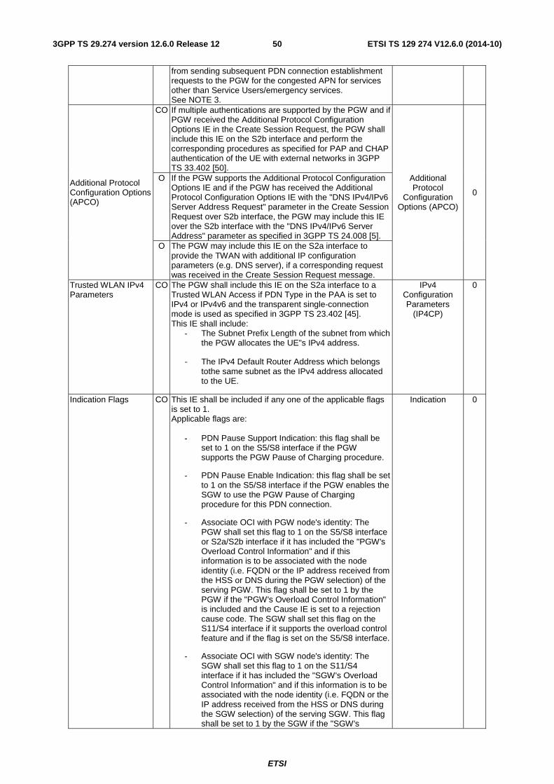
ETSI
ETSI TS 129 274 V12.6.0 (2014-10)503GPP TS 29.274 version 12.6.0 Release 12
from sending subsequent PDN connection establishment requests to the PGW for the congested APN for services other than Service Users/emergency services. See NOTE 3.
Additional Protocol Configuration Options (APCO)
CO If multiple authentications are supported by the PGW and if PGW received the Additional Protocol Configuration Options IE in the Create Session Request, the PGW shall include this IE on the S2b interface and perform the corresponding procedures as specified for PAP and CHAP authentication of the UE with external networks in 3GPP TS 33.402 [50].
Additional Protocol
Configuration Options (APCO)
0
O If the PGW supports the Additional Protocol Configuration Options IE and if the PGW has received the Additional Protocol Configuration Options IE with the "DNS IPv4/IPv6 Server Address Request" parameter in the Create Session Request over S2b interface, the PGW may include this IE over the S2b interface with the "DNS IPv4/IPv6 Server Address" parameter as specified in 3GPP TS 24.008 [5].
O The PGW may include this IE on the S2a interface to provide the TWAN with additional IP configuration parameters (e.g. DNS server), if a corresponding request was received in the Create Session Request message.
Trusted WLAN IPv4 Parameters
CO The PGW shall include this IE on the S2a interface to a Trusted WLAN Access if PDN Type in the PAA is set to IPv4 or IPv4v6 and the transparent single-connection mode is used as specified in 3GPP TS 23.402 [45]. This IE shall include:
- The Subnet Prefix Length of the subnet from which the PGW allocates the UE"s IPv4 address.
- The IPv4 Default Router Address which belongs tothe same subnet as the IPv4 address allocated to the UE.
IPv4 Configuration Parameters
(IP4CP)
0
Indication Flags CO This IE shall be included if any one of the applicable flags is set to 1. Applicable flags are:
- PDN Pause Support Indication: this flag shall be set to 1 on the S5/S8 interface if the PGW supports the PGW Pause of Charging procedure.
- PDN Pause Enable Indication: this flag shall be set to 1 on the S5/S8 interface if the PGW enables the SGW to use the PGW Pause of Charging procedure for this PDN connection.
- Associate OCI with PGW node's identity: The PGW shall set this flag to 1 on the S5/S8 interface or S2a/S2b interface if it has included the "PGW's Overload Control Information" and if this information is to be associated with the node identity (i.e. FQDN or the IP address received from the HSS or DNS during the PGW selection) of the serving PGW. This flag shall be set to 1 by the PGW if the "PGW's Overload Control Information" is included and the Cause IE is set to a rejection cause code. The SGW shall set this flag on the S11/S4 interface if it supports the overload control feature and if the flag is set on the S5/S8 interface.
- Associate OCI with SGW node's identity: The SGW shall set this flag to 1 on the S11/S4 interface if it has included the "SGW's Overload Control Information" and if this information is to be associated with the node identity (i.e. FQDN or the IP address received from the HSS or DNS during the SGW selection) of the serving SGW. This flag shall be set to 1 by the SGW if the "SGW's
Indication 0

ETSI
ETSI TS 129 274 V12.6.0 (2014-10)513GPP TS 29.274 version 12.6.0 Release 12
Overload Control Information" is included and the Cause IE is set to a rejection cause code.
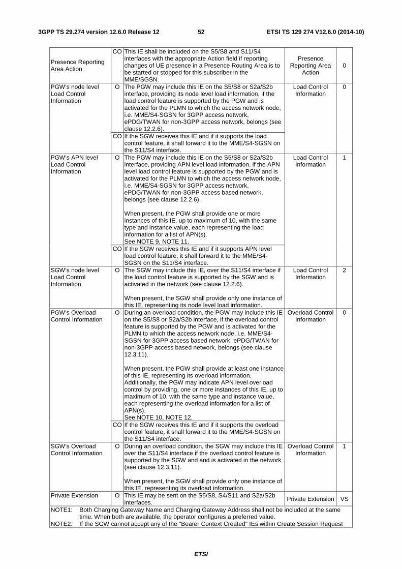
ETSI
ETSI TS 129 274 V12.6.0 (2014-10)523GPP TS 29.274 version 12.6.0 Release 12
Presence Reporting Area Action
CO This IE shall be included on the S5/S8 and S11/S4 interfaces with the appropriate Action field if reporting changes of UE presence in a Presence Routing Area is to be started or stopped for this subscriber in the MME/SGSN.
Presence Reporting Area
Action 0
PGW's node level Load Control Information
O The PGW may include this IE on the S5/S8 or S2a/S2b interface, providing its node level load information, if the load control feature is supported by the PGW and is activated for the PLMN to which the access network node, i.e. MME/S4-SGSN for 3GPP access network, ePDG/TWAN for non-3GPP access network, belongs (see clause 12.2.6).
Load Control Information
0
CO If the SGW receives this IE and if it supports the load control feature, it shall forward it to the MME/S4-SGSN on the S11/S4 interface.
PGW's APN level Load Control Information
O The PGW may include this IE on the S5/S8 or S2a/S2b interface, providing APN level load information, if the APN level load control feature is supported by the PGW and is activated for the PLMN to which the access network node, i.e. MME/S4-SGSN for 3GPP access network, ePDG/TWAN for non-3GPP access based network, belongs (see clause 12.2.6). When present, the PGW shall provide one or more instances of this IE, up to maximum of 10, with the same type and instance value, each representing the load information for a list of APN(s). See NOTE 9, NOTE 11.
Load Control Information
1
CO If the SGW receives this IE and if it supports APN level load control feature, it shall forward it to the MME/S4-SGSN on the S11/S4 interface.
SGW's node level Load Control Information
O The SGW may include this IE, over the S11/S4 interface if the load control feature is supported by the SGW and is activated in the network (see clause 12.2.6). When present, the SGW shall provide only one instance of this IE, representing its node level load information.
Load Control Information
2
PGW's Overload Control Information
O During an overload condition, the PGW may include this IE on the S5/S8 or S2a/S2b interface, if the overload control feature is supported by the PGW and is activated for the PLMN to which the access network node, i.e. MME/S4-SGSN for 3GPP access based network, ePDG/TWAN for non-3GPP access based network, belongs (see clause 12.3.11). When present, the PGW shall provide at least one instance of this IE, representing its overload information. Additionally, the PGW may indicate APN level overload control by providing, one or more instances of this IE, up to maximum of 10, with the same type and instance value, each representing the overload information for a list of APN(s). See NOTE 10, NOTE 12.
Overload Control Information
0
CO If the SGW receives this IE and if it supports the overload control feature, it shall forward it to the MME/S4-SGSN on the S11/S4 interface.
SGW's Overload Control Information
O During an overload condition, the SGW may include this IE over the S11/S4 interface if the overload control feature is supported by the SGW and and is activated in the network (see clause 12.3.11). When present, the SGW shall provide only one instance of this IE, representing its overload information.
Overload Control Information
1
Private Extension O This IE may be sent on the S5/S8, S4/S11 and S2a/S2b interfaces.
Private Extension VS
NOTE1: Both Charging Gateway Name and Charging Gateway Address shall not be included at the same time. When both are available, the operator configures a preferred value.
NOTE2: If the SGW cannot accept any of the "Bearer Context Created" IEs within Create Session Request
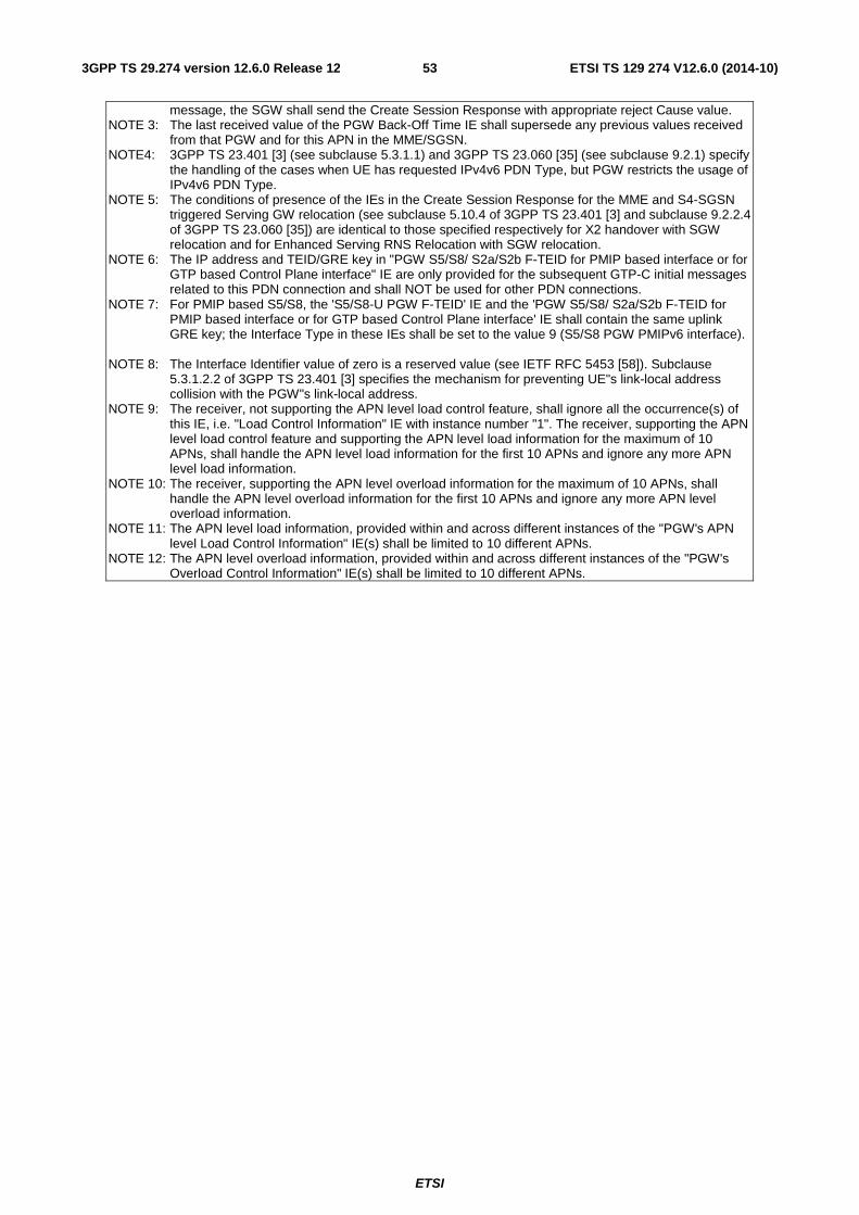
ETSI
ETSI TS 129 274 V12.6.0 (2014-10)533GPP TS 29.274 version 12.6.0 Release 12
message, the SGW shall send the Create Session Response with appropriate reject Cause value. NOTE 3: The last received value of the PGW Back-Off Time IE shall supersede any previous values received
from that PGW and for this APN in the MME/SGSN. NOTE4: 3GPP TS 23.401 [3] (see subclause 5.3.1.1) and 3GPP TS 23.060 [35] (see subclause 9.2.1) specify
the handling of the cases when UE has requested IPv4v6 PDN Type, but PGW restricts the usage of IPv4v6 PDN Type.
NOTE 5: The conditions of presence of the IEs in the Create Session Response for the MME and S4-SGSN triggered Serving GW relocation (see subclause 5.10.4 of 3GPP TS 23.401 [3] and subclause 9.2.2.4 of 3GPP TS 23.060 [35]) are identical to those specified respectively for X2 handover with SGW relocation and for Enhanced Serving RNS Relocation with SGW relocation.
NOTE 6: The IP address and TEID/GRE key in "PGW S5/S8/ S2a/S2b F-TEID for PMIP based interface or for GTP based Control Plane interface" IE are only provided for the subsequent GTP-C initial messages related to this PDN connection and shall NOT be used for other PDN connections.
NOTE 7: For PMIP based S5/S8, the 'S5/S8-U PGW F-TEID' IE and the 'PGW S5/S8/ S2a/S2b F-TEID for PMIP based interface or for GTP based Control Plane interface' IE shall contain the same uplink GRE key; the Interface Type in these IEs shall be set to the value 9 (S5/S8 PGW PMIPv6 interface).
NOTE 8: The Interface Identifier value of zero is a reserved value (see IETF RFC 5453 [58]). Subclause
5.3.1.2.2 of 3GPP TS 23.401 [3] specifies the mechanism for preventing UE"s link-local address collision with the PGW"s link-local address.
NOTE 9: The receiver, not supporting the APN level load control feature, shall ignore all the occurrence(s) of this IE, i.e. "Load Control Information" IE with instance number "1". The receiver, supporting the APN level load control feature and supporting the APN level load information for the maximum of 10 APNs, shall handle the APN level load information for the first 10 APNs and ignore any more APN level load information.
NOTE 10: The receiver, supporting the APN level overload information for the maximum of 10 APNs, shall handle the APN level overload information for the first 10 APNs and ignore any more APN level overload information.
NOTE 11: The APN level load information, provided within and across different instances of the "PGW's APN level Load Control Information" IE(s) shall be limited to 10 different APNs.
NOTE 12: The APN level overload information, provided within and across different instances of the "PGW's Overload Control Information" IE(s) shall be limited to 10 different APNs.
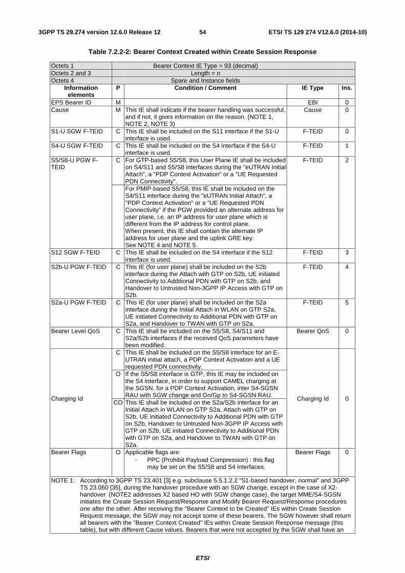
ETSI
ETSI TS 129 274 V12.6.0 (2014-10)543GPP TS 29.274 version 12.6.0 Release 12
Table 7.2.2-2: Bearer Context Created within Create Session Response
Octets 1 Bearer Context IE Type = 93 (decimal) Octets 2 and 3 Length = n Octets 4 Spare and Instance fields
Information elements
P Condition / Comment IE Type Ins.
EPS Bearer ID M EBI 0 Cause M This IE shall indicate if the bearer handling was successful,
and if not, it gives information on the reason. (NOTE 1, NOTE 2, NOTE 3)
Cause 0
S1-U SGW F-TEID C This IE shall be included on the S11 interface if the S1-U interface is used.
F-TEID 0
S4-U SGW F-TEID C This IE shall be included on the S4 interface if the S4-U interface is used.
F-TEID 1
S5/S8-U PGW F-TEID
C For GTP-based S5/S8, this User Plane IE shall be included on S4/S11 and S5/S8 interfaces during the "eUTRAN Initial Attach", a "PDP Context Activation" or a "UE Requested PDN Connectivity".
F-TEID 2
For PMIP-based S5/S8, this IE shall be included on the S4/S11 interface during the "eUTRAN Initial Attach", a "PDP Context Activation" or a "UE Requested PDN Connectivity" if the PGW provided an alternate address for user plane, i.e. an IP address for user plane which is different from the IP address for control plane. When present, this IE shall contain the alternate IP address for user plane and the uplink GRE key. See NOTE 4 and NOTE 5.
S12 SGW F-TEID C This IE shall be included on the S4 interface if the S12 interface is used.
F-TEID 3
S2b-U PGW F-TEID C This IE (for user plane) shall be included on the S2b interface during the Attach with GTP on S2b, UE initiated Connectivity to Additional PDN with GTP on S2b, and Handover to Untrusted Non-3GPP IP Access with GTP on S2b.
F-TEID 4
S2a-U PGW F-TEID C This IE (for user plane) shall be included on the S2a interface during the Initial Attach in WLAN on GTP S2a, UE initiated Connectivity to Additional PDN with GTP on S2a, and Handover to TWAN with GTP on S2a.
F-TEID 5
Bearer Level QoS C This IE shall be included on the S5/S8, S4/S11 and S2a/S2b interfaces if the received QoS parameters have been modified.
Bearer QoS 0
Charging Id
C This IE shall be included on the S5/S8 interface for an E-UTRAN initial attach, a PDP Context Activation and a UE requested PDN connectivity.
Charging Id 0
O If the S5/S8 interface is GTP, this IE may be included on the S4 interface, in order to support CAMEL charging at the SGSN, for a PDP Context Activation, inter S4-SGSN RAU with SGW change and Gn/Gp to S4-SGSN RAU.
CO This IE shall be included on the S2a/S2b interface for an Initial Attach in WLAN on GTP S2a, Attach with GTP on S2b, UE initiated Connectivity to Additional PDN with GTP on S2b, Handover to Untrusted Non-3GPP IP Access with GTP on S2b, UE initiated Connectivity to Additional PDN with GTP on S2a, and Handover to TWAN with GTP on S2a.
Bearer Flags O Applicable flags are: - PPC (Prohibit Payload Compression) : this flag
may be set on the S5/S8 and S4 interfaces.
Bearer Flags 0
NOTE 1: According to 3GPP TS 23.401 [3] e.g. subclause 5.5.1.2.2 "S1-based handover, normal" and 3GPP TS 23.060 [35], during the handover procedure with an SGW change, except in the case of X2-handover (NOTE2 addresses X2 based HO with SGW change case), the target MME/S4-SGSN initiates the Create Session Request/Response and Modify Bearer Request/Response procedures one after the other. After receiving the "Bearer Context to be Created" IEs within Create Session Request message, the SGW may not accept some of these bearers. The SGW however shall return all bearers with the "Bearer Context Created" IEs within Create Session Response message (this table), but with different Cause values. Bearers that were not accepted by the SGW shall have an
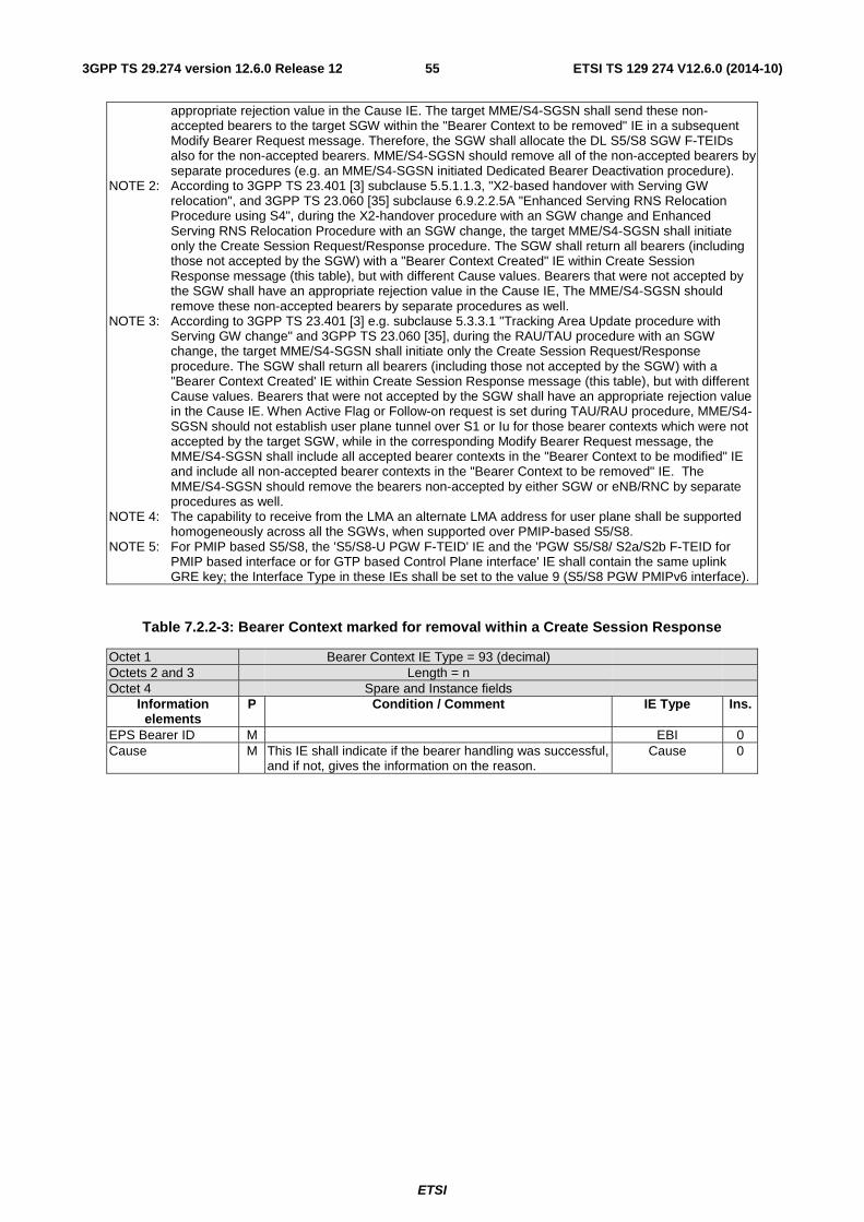
ETSI
ETSI TS 129 274 V12.6.0 (2014-10)553GPP TS 29.274 version 12.6.0 Release 12
appropriate rejection value in the Cause IE. The target MME/S4-SGSN shall send these non-accepted bearers to the target SGW within the "Bearer Context to be removed" IE in a subsequent Modify Bearer Request message. Therefore, the SGW shall allocate the DL S5/S8 SGW F-TEIDs also for the non-accepted bearers. MME/S4-SGSN should remove all of the non-accepted bearers by separate procedures (e.g. an MME/S4-SGSN initiated Dedicated Bearer Deactivation procedure).
NOTE 2: According to 3GPP TS 23.401 [3] subclause 5.5.1.1.3, "X2-based handover with Serving GW relocation", and 3GPP TS 23.060 [35] subclause 6.9.2.2.5A "Enhanced Serving RNS Relocation Procedure using S4", during the X2-handover procedure with an SGW change and Enhanced Serving RNS Relocation Procedure with an SGW change, the target MME/S4-SGSN shall initiate only the Create Session Request/Response procedure. The SGW shall return all bearers (including those not accepted by the SGW) with a "Bearer Context Created" IE within Create Session Response message (this table), but with different Cause values. Bearers that were not accepted by the SGW shall have an appropriate rejection value in the Cause IE, The MME/S4-SGSN should remove these non-accepted bearers by separate procedures as well.
NOTE 3: According to 3GPP TS 23.401 [3] e.g. subclause 5.3.3.1 "Tracking Area Update procedure with Serving GW change" and 3GPP TS 23.060 [35], during the RAU/TAU procedure with an SGW change, the target MME/S4-SGSN shall initiate only the Create Session Request/Response procedure. The SGW shall return all bearers (including those not accepted by the SGW) with a "Bearer Context Created' IE within Create Session Response message (this table), but with different Cause values. Bearers that were not accepted by the SGW shall have an appropriate rejection value in the Cause IE. When Active Flag or Follow-on request is set during TAU/RAU procedure, MME/S4-SGSN should not establish user plane tunnel over S1 or Iu for those bearer contexts which were not accepted by the target SGW, while in the corresponding Modify Bearer Request message, the MME/S4-SGSN shall include all accepted bearer contexts in the "Bearer Context to be modified" IE and include all non-accepted bearer contexts in the "Bearer Context to be removed" IE. The MME/S4-SGSN should remove the bearers non-accepted by either SGW or eNB/RNC by separate procedures as well.
NOTE 4: The capability to receive from the LMA an alternate LMA address for user plane shall be supported homogeneously across all the SGWs, when supported over PMIP-based S5/S8.
NOTE 5: For PMIP based S5/S8, the 'S5/S8-U PGW F-TEID' IE and the 'PGW S5/S8/ S2a/S2b F-TEID for PMIP based interface or for GTP based Control Plane interface' IE shall contain the same uplink GRE key; the Interface Type in these IEs shall be set to the value 9 (S5/S8 PGW PMIPv6 interface).
Table 7.2.2-3: Bearer Context marked for removal within a Create Session Response
Octet 1 Bearer Context IE Type = 93 (decimal) Octets 2 and 3 Length = n Octet 4 Spare and Instance fields
Information elements
P Condition / Comment IE Type Ins.
EPS Bearer ID M EBI 0 Cause M This IE shall indicate if the bearer handling was successful,
and if not, gives the information on the reason. Cause 0
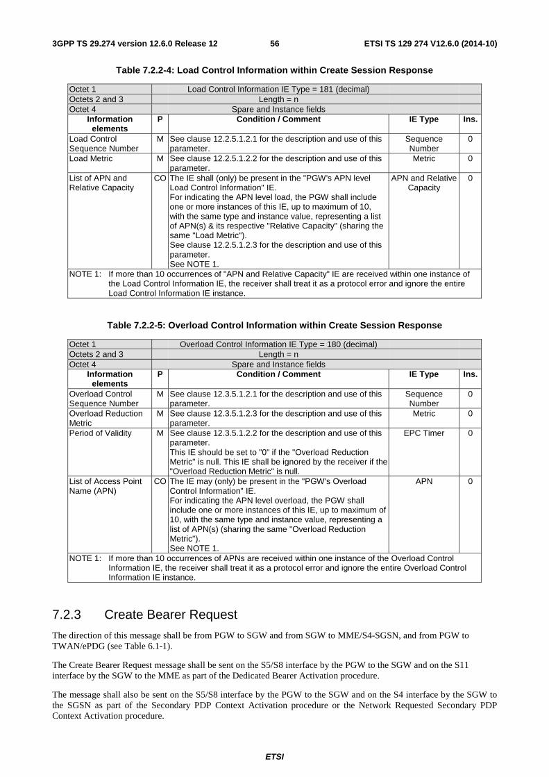
ETSI
ETSI TS 129 274 V12.6.0 (2014-10)563GPP TS 29.274 version 12.6.0 Release 12
Table 7.2.2-4: Load Control Information within Create Session Response
Octet 1 Load Control Information IE Type = 181 (decimal) Octets 2 and 3 Length = n Octet 4 Spare and Instance fields
Information elements
P Condition / Comment IE Type Ins.
Load Control Sequence Number
M See clause 12.2.5.1.2.1 for the description and use of this parameter.
Sequence Number
0
Load Metric M See clause 12.2.5.1.2.2 for the description and use of this parameter.
Metric 0
List of APN and Relative Capacity
CO The IE shall (only) be present in the "PGW's APN level Load Control Information" IE. For indicating the APN level load, the PGW shall include one or more instances of this IE, up to maximum of 10, with the same type and instance value, representing a list of APN(s) & its respective "Relative Capacity" (sharing the same "Load Metric"). See clause 12.2.5.1.2.3 for the description and use of this parameter. See NOTE 1.
APN and Relative Capacity
0
NOTE 1: If more than 10 occurrences of "APN and Relative Capacity" IE are received within one instance of the Load Control Information IE, the receiver shall treat it as a protocol error and ignore the entire Load Control Information IE instance.
Table 7.2.2-5: Overload Control Information within Create Session Response
Octet 1 Overload Control Information IE Type = 180 (decimal) Octets 2 and 3 Length = n Octet 4 Spare and Instance fields
Information elements
P Condition / Comment IE Type Ins.
Overload Control Sequence Number
M See clause 12.3.5.1.2.1 for the description and use of this parameter.
Sequence Number
0
Overload Reduction Metric
M See clause 12.3.5.1.2.3 for the description and use of this parameter.
Metric 0
Period of Validity M See clause 12.3.5.1.2.2 for the description and use of this parameter. This IE should be set to "0" if the "Overload Reduction Metric" is null. This IE shall be ignored by the receiver if the "Overload Reduction Metric" is null.
EPC Timer 0
List of Access Point Name (APN)
CO The IE may (only) be present in the "PGW's Overload Control Information" IE. For indicating the APN level overload, the PGW shall include one or more instances of this IE, up to maximum of 10, with the same type and instance value, representing a list of APN(s) (sharing the same "Overload Reduction Metric"). See NOTE 1.
APN 0
NOTE 1: If more than 10 occurrences of APNs are received within one instance of the Overload Control Information IE, the receiver shall treat it as a protocol error and ignore the entire Overload Control Information IE instance.
7.2.3 Create Bearer Request
The direction of this message shall be from PGW to SGW and from SGW to MME/S4-SGSN, and from PGW to TWAN/ePDG (see Table 6.1-1).
The Create Bearer Request message shall be sent on the S5/S8 interface by the PGW to the SGW and on the S11 interface by the SGW to the MME as part of the Dedicated Bearer Activation procedure.
The message shall also be sent on the S5/S8 interface by the PGW to the SGW and on the S4 interface by the SGW to the SGSN as part of the Secondary PDP Context Activation procedure or the Network Requested Secondary PDP Context Activation procedure.

ETSI
ETSI TS 129 274 V12.6.0 (2014-10)573GPP TS 29.274 version 12.6.0 Release 12
The message shall also be sent on the S2a interface by the PGW to the TWAN as part of the Dedicated bearer activation in WLAN on GTP S2a, and on the S2b interface by the PGW to the ePDG as part of the Dedicated S2b bearer activation with GTP on S2b.
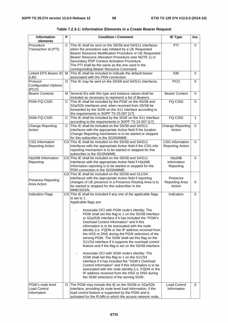
ETSI
ETSI TS 129 274 V12.6.0 (2014-10)583GPP TS 29.274 version 12.6.0 Release 12
Table 7.2.3-1: Information Elements in a Create Bearer Request
Information elements
P Condition / Comment IE Type Ins.
Procedure Transaction Id (PTI)
C This IE shall be sent on the S5/S8 and S4/S11 interfaces when the procedure was initiated by a UE Requested Bearer Resource Modification Procedure or UE Requested Bearer Resource Allocation Procedure (see NOTE 1) or Secondary PDP Context Activation Procedure. The PTI shall be the same as the one used in the corresponding Bearer Resource Command.
PTI 0
Linked EPS Bearer ID (LBI)
M This IE shall be included to indicate the default bearer associated with the PDN connection.
EBI 0
Protocol Configuration Options (PCO)
O This IE may be sent on the S5/S8 and S4/S11 interfaces. PCO 0
Bearer Contexts M Several IEs with this type and instance values shall be included as necessary to represent a list of Bearers.
Bearer Context 0
PGW-FQ-CSID C This IE shall be included by the PGW on the S5/S8 and S2a/S2b interfaces and, when received from S5/S8 be forwarded by the SGW on the S11 interface according to the requirements in 3GPP TS 23.007 [17].
FQ-CSID 0
SGW-FQ-CSID C This IE shall be included by the SGW on the S11 interface according to the requirements in 3GPP TS 23.007 [17].
FQ-CSID 1
Change Reporting Action
C This IE shall be included on the S5/S8 and S4/S11 interfaces with the appropriate Action field If the location Change Reporting mechanism is to be started or stopped for this subscriber in the SGSN/MME.
Change Reporting Action
0
CSG Information Reporting Action
CO This IE shall be included on the S5/S8 and S4/S11 interfaces with the appropriate Action field if the CSG Info reporting mechanism is to be started or stopped for this subscriber in the SGSN/MME.
CSG Information Reporting Action
0
H(e)NB Information Reporting
CO This IE shall be included on the S5/S8 and S4/S11 interfaces with the appropriate Action field if H(e)NB information reporting is to be started or stopped for the PDN connection in the SGSN/MME.
H(e)NB Information Reporting
0
Presence Reporting Area Action
CO This IE shall be included on the S5/S8 and S11/S4 interfaces with the appropriate Action field if reporting changes of UE presence in a Presence Routing Area is to be started or stopped for this subscriber in the MME/SGSN.
Presence Reporting Area
Action 0
Indication Flags CO This IE shall be included if any one of the applicable flags is set to 1. Applicable flags are:
- Associate OCI with PGW node's identity: The PGW shall set this flag to 1 on the S5/S8 interface or S2a/S2b interface if it has included the "PGW's Overload Control Information" and if this information is to be associated with the node identity (i.e. FQDN or the IP address received from the HSS or DNS during the PGW selection) of the serving PGW. The SGW shall set this flag on the S11/S4 interface if it supports the overload control feature and if the flag is set on the S5/S8 interface.
- Associate OCI with SGW node's identity: The SGW shall set this flag to 1 on the S11/S4 interface if it has included the "SGW's Overload Control Information" and if this information is to be associated with the node identity (i.e. FQDN or the IP address received from the HSS or DNS during the SGW selection) of the serving SGW.
Indication 0
PGW's node level Load Control Information
O The PGW may include this IE on the S5/S8 or S2a/S2b interface, providing its node level load information, if the load control feature is supported by the PGW and is activated for the PLMN to which the access network node,
Load Control Information
0
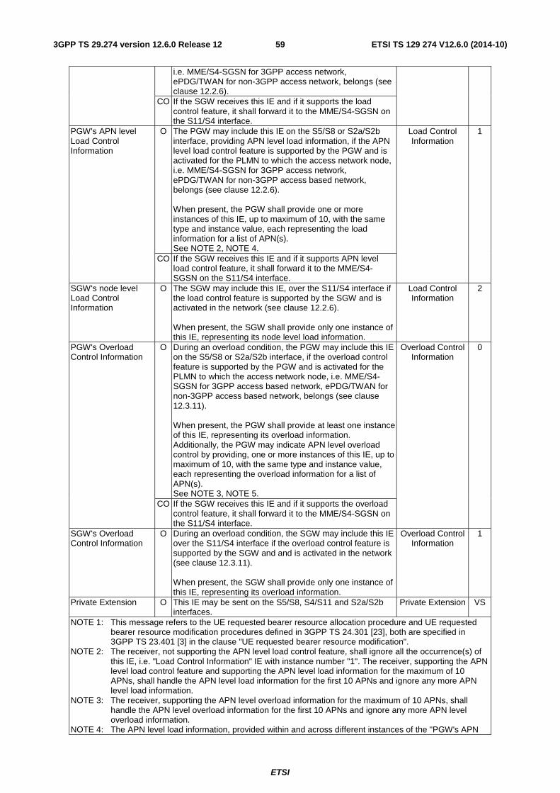
ETSI
ETSI TS 129 274 V12.6.0 (2014-10)593GPP TS 29.274 version 12.6.0 Release 12
i.e. MME/S4-SGSN for 3GPP access network, ePDG/TWAN for non-3GPP access network, belongs (see clause 12.2.6).
CO If the SGW receives this IE and if it supports the load control feature, it shall forward it to the MME/S4-SGSN on the S11/S4 interface.
PGW's APN level Load Control Information
O The PGW may include this IE on the S5/S8 or S2a/S2b interface, providing APN level load information, if the APN level load control feature is supported by the PGW and is activated for the PLMN to which the access network node, i.e. MME/S4-SGSN for 3GPP access network, ePDG/TWAN for non-3GPP access based network, belongs (see clause 12.2.6). When present, the PGW shall provide one or more instances of this IE, up to maximum of 10, with the same type and instance value, each representing the load information for a list of APN(s). See NOTE 2, NOTE 4.
Load Control Information
1
CO If the SGW receives this IE and if it supports APN level load control feature, it shall forward it to the MME/S4-SGSN on the S11/S4 interface.
SGW's node level Load Control Information
O The SGW may include this IE, over the S11/S4 interface if the load control feature is supported by the SGW and is activated in the network (see clause 12.2.6). When present, the SGW shall provide only one instance of this IE, representing its node level load information.
Load Control Information
2
PGW's Overload Control Information
O During an overload condition, the PGW may include this IE on the S5/S8 or S2a/S2b interface, if the overload control feature is supported by the PGW and is activated for the PLMN to which the access network node, i.e. MME/S4-SGSN for 3GPP access based network, ePDG/TWAN for non-3GPP access based network, belongs (see clause 12.3.11). When present, the PGW shall provide at least one instance of this IE, representing its overload information. Additionally, the PGW may indicate APN level overload control by providing, one or more instances of this IE, up to maximum of 10, with the same type and instance value, each representing the overload information for a list of APN(s). See NOTE 3, NOTE 5.
Overload Control Information
0
CO If the SGW receives this IE and if it supports the overload control feature, it shall forward it to the MME/S4-SGSN on the S11/S4 interface.
SGW's Overload Control Information
O During an overload condition, the SGW may include this IE over the S11/S4 interface if the overload control feature is supported by the SGW and and is activated in the network (see clause 12.3.11). When present, the SGW shall provide only one instance of this IE, representing its overload information.
Overload Control Information
1
Private Extension O This IE may be sent on the S5/S8, S4/S11 and S2a/S2b interfaces.
Private Extension VS
NOTE 1: This message refers to the UE requested bearer resource allocation procedure and UE requested bearer resource modification procedures defined in 3GPP TS 24.301 [23], both are specified in 3GPP TS 23.401 [3] in the clause "UE requested bearer resource modification".
NOTE 2: The receiver, not supporting the APN level load control feature, shall ignore all the occurrence(s) of this IE, i.e. "Load Control Information" IE with instance number "1". The receiver, supporting the APN level load control feature and supporting the APN level load information for the maximum of 10 APNs, shall handle the APN level load information for the first 10 APNs and ignore any more APN level load information.
NOTE 3: The receiver, supporting the APN level overload information for the maximum of 10 APNs, shall handle the APN level overload information for the first 10 APNs and ignore any more APN level overload information.
NOTE 4: The APN level load information, provided within and across different instances of the "PGW's APN
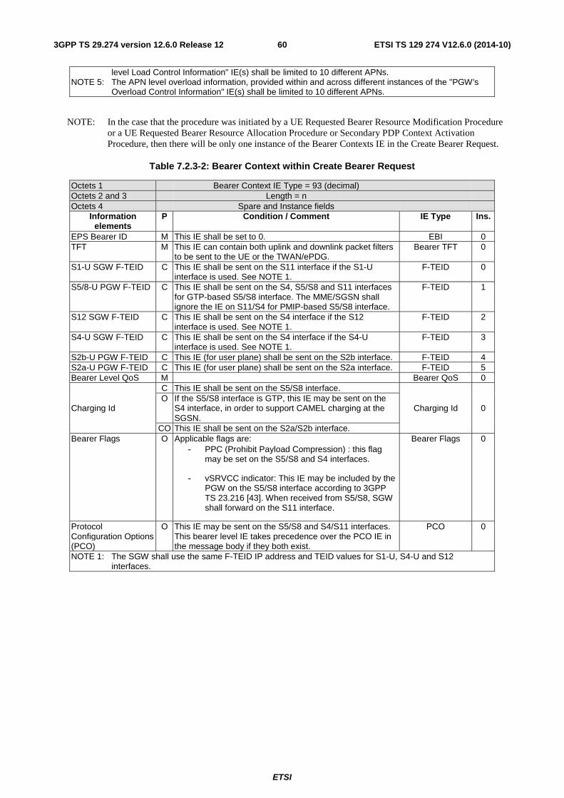
ETSI
ETSI TS 129 274 V12.6.0 (2014-10)603GPP TS 29.274 version 12.6.0 Release 12
level Load Control Information" IE(s) shall be limited to 10 different APNs. NOTE 5: The APN level overload information, provided within and across different instances of the "PGW's
Overload Control Information" IE(s) shall be limited to 10 different APNs.
NOTE: In the case that the procedure was initiated by a UE Requested Bearer Resource Modification Procedure or a UE Requested Bearer Resource Allocation Procedure or Secondary PDP Context Activation Procedure, then there will be only one instance of the Bearer Contexts IE in the Create Bearer Request.
Table 7.2.3-2: Bearer Context within Create Bearer Request
Octets 1 Bearer Context IE Type = 93 (decimal) Octets 2 and 3 Length = n Octets 4 Spare and Instance fields
Information elements
P Condition / Comment IE Type Ins.
EPS Bearer ID M This IE shall be set to 0. EBI 0 TFT M This IE can contain both uplink and downlink packet filters
to be sent to the UE or the TWAN/ePDG. Bearer TFT 0
S1-U SGW F-TEID C This IE shall be sent on the S11 interface if the S1-U interface is used. See NOTE 1.
F-TEID 0
S5/8-U PGW F-TEID C This IE shall be sent on the S4, S5/S8 and S11 interfaces for GTP-based S5/S8 interface. The MME/SGSN shall ignore the IE on S11/S4 for PMIP-based S5/S8 interface.
F-TEID 1
S12 SGW F-TEID C This IE shall be sent on the S4 interface if the S12 interface is used. See NOTE 1.
F-TEID 2
S4-U SGW F-TEID C This IE shall be sent on the S4 interface if the S4-U interface is used. See NOTE 1.
F-TEID 3
S2b-U PGW F-TEID C This IE (for user plane) shall be sent on the S2b interface. F-TEID 4 S2a-U PGW F-TEID C This IE (for user plane) shall be sent on the S2a interface. F-TEID 5 Bearer Level QoS M Bearer QoS 0
Charging Id
C This IE shall be sent on the S5/S8 interface.
Charging Id 0 O If the S5/S8 interface is GTP, this IE may be sent on the
S4 interface, in order to support CAMEL charging at the SGSN.
CO This IE shall be sent on the S2a/S2b interface. Bearer Flags O Applicable flags are:
- PPC (Prohibit Payload Compression) : this flag may be set on the S5/S8 and S4 interfaces.
- vSRVCC indicator: This IE may be included by the PGW on the S5/S8 interface according to 3GPP TS 23.216 [43]. When received from S5/S8, SGW shall forward on the S11 interface.
Bearer Flags 0
Protocol Configuration Options (PCO)
O This IE may be sent on the S5/S8 and S4/S11 interfaces. This bearer level IE takes precedence over the PCO IE in the message body if they both exist.
PCO 0
NOTE 1: The SGW shall use the same F-TEID IP address and TEID values for S1-U, S4-U and S12 interfaces.
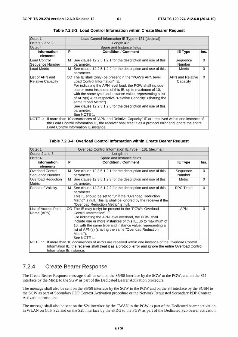
ETSI
ETSI TS 129 274 V12.6.0 (2014-10)613GPP TS 29.274 version 12.6.0 Release 12
Table 7.2.3-3: Load Control Information within Create Bearer Request
Octet 1 Load Control Information IE Type = 181 (decimal) Octets 2 and 3 Length = n Octet 4 Spare and Instance fields
Information elements
P Condition / Comment IE Type Ins.
Load Control Sequence Number
M See clause 12.2.5.1.2.1 for the description and use of this parameter.
Sequence Number
0
Load Metric M See clause 12.2.5.1.2.2 for the description and use of this parameter.
Metric 0
List of APN and Relative Capacity
CO The IE shall (only) be present in the "PGW's APN level Load Control Information" IE. For indicating the APN level load, the PGW shall include one or more instances of this IE, up to maximum of 10, with the same type and instance value, representing a list of APN(s) & its respective "Relative Capacity" (sharing the same "Load Metric"). See clause 12.2.5.1.2.3 for the description and use of this parameter. See NOTE 1.
APN and Relative Capacity
0
NOTE 1: If more than 10 occurrences of "APN and Relative Capacity" IE are received within one instance of the Load Control Information IE, the receiver shall treat it as a protocol error and ignore the entire Load Control Information IE instance.
Table 7.2.3-4: Overload Control Information within Create Bearer Request
Octet 1 Overload Control Information IE Type = 181 (decimal) Octets 2 and 3 Length = n Octet 4 Spare and Instance fields
Information elements
P Condition / Comment IE Type Ins.
Overload Control Sequence Number
M See clause 12.3.5.1.2.1 for the description and use of this parameter.
Sequence Number
0
Overload Reduction Metric
M See clause 12.3.5.1.2.3 for the description and use of this parameter.
Metric 0
Period of Validity M See clause 12.3.5.1.2.2 for the description and use of this parameter. This IE should be set to "0" if the "Overload Reduction Metric" is null. This IE shall be ignored by the receiver if the "Overload Reduction Metric" is null.
EPC Timer 0
List of Access Point Name (APN)
CO The IE may (only) be present in the "PGW's Overload Control Information" IE. For indicating the APN level overload, the PGW shall include one or more instances of this IE, up to maximum of 10, with the same type and instance value, representing a list of APN(s) (sharing the same "Overload Reduction Metric"). See NOTE 1.
APN 0
NOTE 1: If more than 10 occurrences of APNs are received within one instance of the Overload Control Information IE, the receiver shall treat it as a protocol error and ignore the entire Overload Control Information IE instance.
7.2.4 Create Bearer Response
The Create Bearer Response message shall be sent on the S5/S8 interface by the SGW to the PGW, and on the S11 interface by the MME to the SGW as part of the Dedicated Bearer Activation procedure.
The message shall also be sent on the S5/S8 interface by the SGW to the PGW and on the S4 interface by the SGSN to the SGW as part of Secondary PDP Context Activation procedure or the Network Requested Secondary PDP Context Activation procedure.
The message shall also be sent on the S2a interface by the TWAN to the PGW as part of the Dedicated bearer activation in WLAN on GTP S2a and on the S2b interface by the ePDG to the PGW as part of the Dedicated S2b bearer activation
ETSI
ETSI TS 129 274 V12.6.0 (2014-10)623GPP TS 29.274 version 12.6.0 Release 12
with GTP on S2b. Possible Cause values are specified in Table 8.4-1. Message specific cause values are:
- "Request accepted".
- "Request accepted partially".
- "Context not found".
- "Semantic error in the TFT operation".
- "Syntactic error in the TFT operation".
- "Semantic errors in packet filter(s)".
- "Syntactic errors in packet filter(s)".
- "Unable to page UE".
- "UE not responding".
- "Unable to page UE due to Suspension".
- "UE refuses".
- "Denied in RAT".
- "Temporarily rejected due to handover/TAU/RAU procedure in progress".
- "MME/SGSN refuses due to VPLMN Policy".
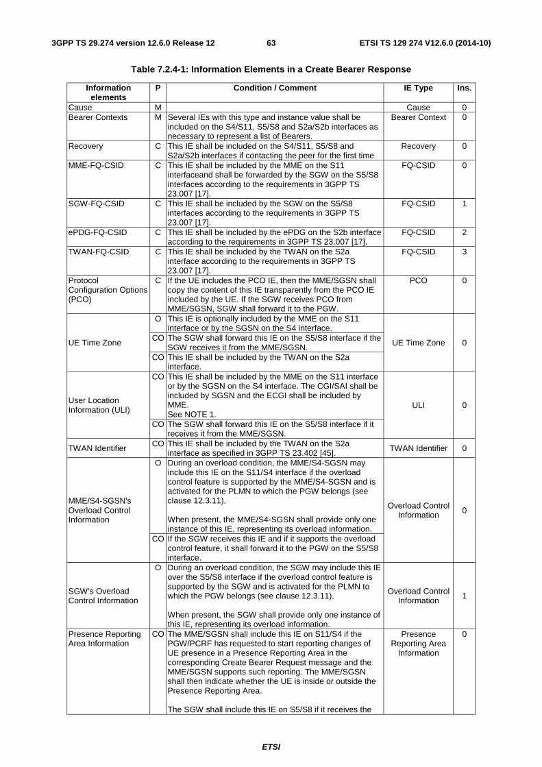
ETSI
ETSI TS 129 274 V12.6.0 (2014-10)633GPP TS 29.274 version 12.6.0 Release 12
Table 7.2.4-1: Information Elements in a Create Bearer Response
Information elements
P Condition / Comment IE Type Ins.
Cause M Cause 0 Bearer Contexts M Several IEs with this type and instance value shall be
included on the S4/S11, S5/S8 and S2a/S2b interfaces as necessary to represent a list of Bearers.
Bearer Context 0
Recovery C This IE shall be included on the S4/S11, S5/S8 and S2a/S2b interfaces if contacting the peer for the first time
Recovery 0
MME-FQ-CSID C This IE shall be included by the MME on the S11 interfaceand shall be forwarded by the SGW on the S5/S8 interfaces according to the requirements in 3GPP TS 23.007 [17].
FQ-CSID 0
SGW-FQ-CSID C This IE shall be included by the SGW on the S5/S8 interfaces according to the requirements in 3GPP TS 23.007 [17].
FQ-CSID 1
ePDG-FQ-CSID C This IE shall be included by the ePDG on the S2b interface according to the requirements in 3GPP TS 23.007 [17].
FQ-CSID 2
TWAN-FQ-CSID C This IE shall be included by the TWAN on the S2a interface according to the requirements in 3GPP TS 23.007 [17].
FQ-CSID 3
Protocol Configuration Options (PCO)
C If the UE includes the PCO IE, then the MME/SGSN shall copy the content of this IE transparently from the PCO IE included by the UE. If the SGW receives PCO from MME/SGSN, SGW shall forward it to the PGW.
PCO 0
UE Time Zone
O This IE is optionally included by the MME on the S11 interface or by the SGSN on the S4 interface.
UE Time Zone 0 CO The SGW shall forward this IE on the S5/S8 interface if the
SGW receives it from the MME/SGSN. CO This IE shall be included by the TWAN on the S2a
interface.
User Location Information (ULI)
CO This IE shall be included by the MME on the S11 interface or by the SGSN on the S4 interface. The CGI/SAI shall be included by SGSN and the ECGI shall be included by MME. See NOTE 1.
ULI 0
CO The SGW shall forward this IE on the S5/S8 interface if it receives it from the MME/SGSN.
TWAN Identifier CO This IE shall be included by the TWAN on the S2a interface as specified in 3GPP TS 23.402 [45]. TWAN Identifier 0
MME/S4-SGSN's Overload Control Information
O During an overload condition, the MME/S4-SGSN may include this IE on the S11/S4 interface if the overload control feature is supported by the MME/S4-SGSN and is activated for the PLMN to which the PGW belongs (see clause 12.3.11). When present, the MME/S4-SGSN shall provide only one instance of this IE, representing its overload information.
Overload Control Information 0
CO If the SGW receives this IE and if it supports the overload control feature, it shall forward it to the PGW on the S5/S8 interface.
SGW's Overload Control Information
O During an overload condition, the SGW may include this IE over the S5/S8 interface if the overload control feature is supported by the SGW and is activated for the PLMN to which the PGW belongs (see clause 12.3.11). When present, the SGW shall provide only one instance of this IE, representing its overload information.
Overload Control Information 1
Presence Reporting Area Information
CO
The MME/SGSN shall include this IE on S11/S4 if the PGW/PCRF has requested to start reporting changes of UE presence in a Presence Reporting Area in the corresponding Create Bearer Request message and the MME/SGSN supports such reporting. The MME/SGSN shall then indicate whether the UE is inside or outside the Presence Reporting Area. The SGW shall include this IE on S5/S8 if it receives the
Presence Reporting Area
Information
0
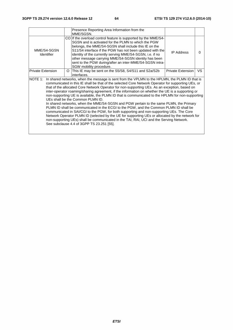
ETSI
ETSI TS 129 274 V12.6.0 (2014-10)643GPP TS 29.274 version 12.6.0 Release 12
Presence Reporting Area Information from the MME/SGSN.
MME/S4-SGSN Identifier
CO If the overload control feature is supported by the MME/S4-SGSN and is activated for the PLMN to which the PGW belongs, the MME/S4-SGSN shall include this IE on the S11/S4 interface if the PGW has not been updated with the identity of the currently serving MME/S4-SGSN, i.e. if no other message carrying MME/S4-SGSN identity has been sent to the PGW during/after an inter-MME/S4-SGSN intra-SGW mobility procedure.
IP Address 0
Private Extension O This IE may be sent on the S5/S8, S4/S11 and S2a/S2b interfaces.
Private Extension VS
NOTE 1: In shared networks, when the message is sent from the VPLMN to the HPLMN, the PLMN ID that is communicated in this IE shall be that of the selected Core Network Operator for supporting UEs, or that of the allocated Core Network Operator for non-supporting UEs. As an exception, based on inter-operator roaming/sharing agreement, if the information on whether the UE is a supporting or non-supporting UE is available, the PLMN ID that is communicated to the HPLMN for non-supporting UEs shall be the Common PLMN ID. In shared networks, when the MME/S4-SGSN and PGW pertain to the same PLMN, the Primary PLMN ID shall be communicated in the ECGI to the PGW, and the Common PLMN ID shall be communicated in SAI/CGI to the PGW, for both supporting and non-supporting UEs. The Core Network Operator PLMN ID (selected by the UE for supporting UEs or allocated by the network for non-supporting UEs) shall be communicated in the TAI, RAI, UCI and the Serving Network. See subclause 4.4 of 3GPP TS 23.251 [55].
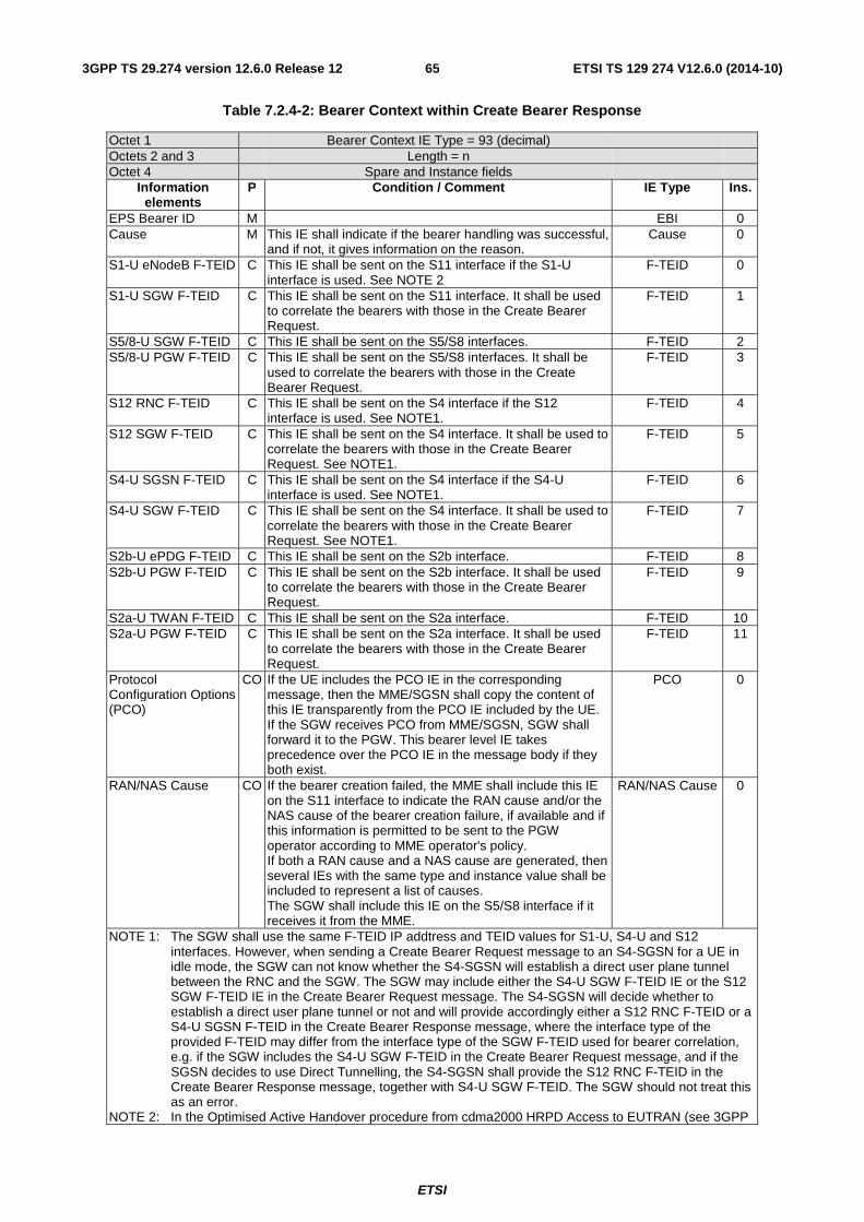
ETSI
ETSI TS 129 274 V12.6.0 (2014-10)653GPP TS 29.274 version 12.6.0 Release 12
Table 7.2.4-2: Bearer Context within Create Bearer Response
Octet 1 Bearer Context IE Type = 93 (decimal) Octets 2 and 3 Length = n Octet 4 Spare and Instance fields
Information elements
P Condition / Comment IE Type Ins.
EPS Bearer ID M EBI 0 Cause M This IE shall indicate if the bearer handling was successful,
and if not, it gives information on the reason. Cause 0
S1-U eNodeB F-TEID C This IE shall be sent on the S11 interface if the S1-U interface is used. See NOTE 2
F-TEID 0
S1-U SGW F-TEID C This IE shall be sent on the S11 interface. It shall be used to correlate the bearers with those in the Create Bearer Request.
F-TEID 1
S5/8-U SGW F-TEID C This IE shall be sent on the S5/S8 interfaces. F-TEID 2 S5/8-U PGW F-TEID C This IE shall be sent on the S5/S8 interfaces. It shall be
used to correlate the bearers with those in the Create Bearer Request.
F-TEID 3
S12 RNC F-TEID C This IE shall be sent on the S4 interface if the S12 interface is used. See NOTE1.
F-TEID 4
S12 SGW F-TEID C This IE shall be sent on the S4 interface. It shall be used to correlate the bearers with those in the Create Bearer Request. See NOTE1.
F-TEID 5
S4-U SGSN F-TEID C This IE shall be sent on the S4 interface if the S4-U interface is used. See NOTE1.
F-TEID 6
S4-U SGW F-TEID C This IE shall be sent on the S4 interface. It shall be used to correlate the bearers with those in the Create Bearer Request. See NOTE1.
F-TEID 7
S2b-U ePDG F-TEID C This IE shall be sent on the S2b interface. F-TEID 8 S2b-U PGW F-TEID C This IE shall be sent on the S2b interface. It shall be used
to correlate the bearers with those in the Create Bearer Request.
F-TEID 9
S2a-U TWAN F-TEID C This IE shall be sent on the S2a interface. F-TEID 10 S2a-U PGW F-TEID C This IE shall be sent on the S2a interface. It shall be used
to correlate the bearers with those in the Create Bearer Request.
F-TEID 11
Protocol Configuration Options (PCO)
CO If the UE includes the PCO IE in the corresponding message, then the MME/SGSN shall copy the content of this IE transparently from the PCO IE included by the UE. If the SGW receives PCO from MME/SGSN, SGW shall forward it to the PGW. This bearer level IE takes precedence over the PCO IE in the message body if they both exist.
PCO 0
RAN/NAS Cause CO
If the bearer creation failed, the MME shall include this IE on the S11 interface to indicate the RAN cause and/or the NAS cause of the bearer creation failure, if available and if this information is permitted to be sent to the PGW operator according to MME operator's policy. If both a RAN cause and a NAS cause are generated, then several IEs with the same type and instance value shall be included to represent a list of causes. The SGW shall include this IE on the S5/S8 interface if it receives it from the MME.
RAN/NAS Cause 0
NOTE 1: The SGW shall use the same F-TEID IP addtress and TEID values for S1-U, S4-U and S12 interfaces. However, when sending a Create Bearer Request message to an S4-SGSN for a UE in idle mode, the SGW can not know whether the S4-SGSN will establish a direct user plane tunnel between the RNC and the SGW. The SGW may include either the S4-U SGW F-TEID IE or the S12 SGW F-TEID IE in the Create Bearer Request message. The S4-SGSN will decide whether to establish a direct user plane tunnel or not and will provide accordingly either a S12 RNC F-TEID or a S4-U SGSN F-TEID in the Create Bearer Response message, where the interface type of the provided F-TEID may differ from the interface type of the SGW F-TEID used for bearer correlation, e.g. if the SGW includes the S4-U SGW F-TEID in the Create Bearer Request message, and if the SGSN decides to use Direct Tunnelling, the S4-SGSN shall provide the S12 RNC F-TEID in the Create Bearer Response message, together with S4-U SGW F-TEID. The SGW should not treat this as an error.
NOTE 2: In the Optimised Active Handover procedure from cdma2000 HRPD Access to EUTRAN (see 3GPP
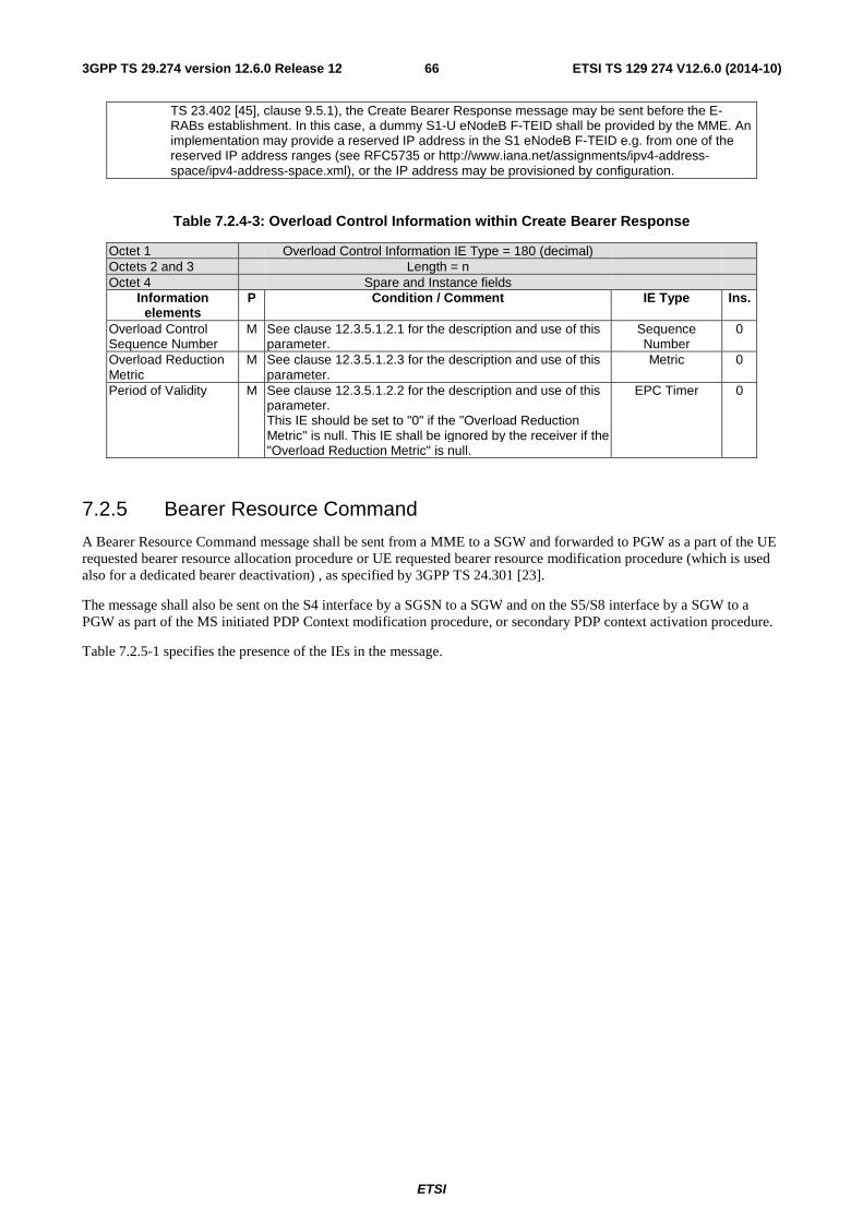
ETSI
ETSI TS 129 274 V12.6.0 (2014-10)663GPP TS 29.274 version 12.6.0 Release 12
TS 23.402 [45], clause 9.5.1), the Create Bearer Response message may be sent before the E-RABs establishment. In this case, a dummy S1-U eNodeB F-TEID shall be provided by the MME. An implementation may provide a reserved IP address in the S1 eNodeB F-TEID e.g. from one of the reserved IP address ranges (see RFC5735 or http://www.iana.net/assignments/ipv4-address-space/ipv4-address-space.xml), or the IP address may be provisioned by configuration.
Table 7.2.4-3: Overload Control Information within Create Bearer Response
Octet 1 Overload Control Information IE Type = 180 (decimal) Octets 2 and 3 Length = n Octet 4 Spare and Instance fields
Information elements
P Condition / Comment IE Type Ins.
Overload Control Sequence Number
M See clause 12.3.5.1.2.1 for the description and use of this parameter.
Sequence Number
0
Overload Reduction Metric
M See clause 12.3.5.1.2.3 for the description and use of this parameter.
Metric 0
Period of Validity M See clause 12.3.5.1.2.2 for the description and use of this parameter. This IE should be set to "0" if the "Overload Reduction Metric" is null. This IE shall be ignored by the receiver if the "Overload Reduction Metric" is null.
EPC Timer 0
7.2.5 Bearer Resource Command
A Bearer Resource Command message shall be sent from a MME to a SGW and forwarded to PGW as a part of the UE requested bearer resource allocation procedure or UE requested bearer resource modification procedure (which is used also for a dedicated bearer deactivation) , as specified by 3GPP TS 24.301 [23].
The message shall also be sent on the S4 interface by a SGSN to a SGW and on the S5/S8 interface by a SGW to a PGW as part of the MS initiated PDP Context modification procedure, or secondary PDP context activation procedure.
Table 7.2.5-1 specifies the presence of the IEs in the message.
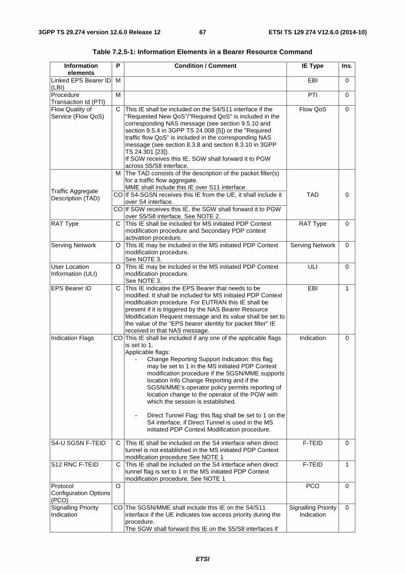
ETSI
ETSI TS 129 274 V12.6.0 (2014-10)673GPP TS 29.274 version 12.6.0 Release 12
Table 7.2.5-1: Information Elements in a Bearer Resource Command
Information elements
P Condition / Comment IE Type Ins.
Linked EPS Bearer ID (LBI)
M EBI 0
Procedure Transaction Id (PTI)
M PTI 0
Flow Quality of Service (Flow QoS)
C This IE shall be included on the S4/S11 interface if the "Requested New QoS"/"Required QoS" is included in the corresponding NAS message (see section 9.5.10 and section 9.5.4 in 3GPP TS 24.008 [5]) or the "Required traffic flow QoS" is included in the corresponding NAS message (see section 8.3.8 and section 8.3.10 in 3GPP TS 24.301 [23]). If SGW receives this IE, SGW shall forward it to PGW across S5/S8 interface.
Flow QoS 0
Traffic Aggregate Description (TAD)
M The TAD consists of the description of the packet filter(s) for a traffic flow aggregate. MME shall include this IE over S11 interface.
TAD 0 CO If S4-SGSN receives this IE from the UE, it shall include it over S4 interface.
CO If SGW receives this IE, the SGW shall forward it to PGW over S5/S8 interface. See NOTE 2.
RAT Type C This IE shall be included for MS initiated PDP Context modification procedure and Secondary PDP context activation procedure.
RAT Type 0
Serving Network O This IE may be included in the MS initiated PDP Context modification procedure. See NOTE 3.
Serving Network 0
User Location Information (ULI)
O This IE may be included in the MS initiated PDP Context modification procedure. See NOTE 3.
ULI 0
EPS Bearer ID C This IE indicates the EPS Bearer that needs to be modified. It shall be included for MS initiated PDP Context modification procedure. For EUTRAN this IE shall be present if it is triggered by the NAS Bearer Resource Modification Request message and its value shall be set to the value of the "EPS bearer identity for packet filter" IE received in that NAS message.
EBI 1
Indication Flags CO This IE shall be included if any one of the applicable flags is set to 1. Applicable flags:
- Change Reporting Support Indication: this flag may be set to 1 in the MS initiated PDP Context modification procedure if the SGSN/MME supports location Info Change Reporting and if the SGSN/MME's operator policy permits reporting of location change to the operator of the PGW with which the session is established.
- Direct Tunnel Flag: this flag shall be set to 1 on the S4 interface, if Direct Tunnel is used in the MS initiated PDP Context Modification procedure.
Indication 0
S4-U SGSN F-TEID C This IE shall be included on the S4 interface when direct tunnel is not established in the MS initiated PDP Context modification procedure See NOTE 1
F-TEID 0
S12 RNC F-TEID C This IE shall be included on the S4 interface when direct tunnel flag is set to 1 in the MS initiated PDP Context modification procedure. See NOTE 1
F-TEID 1
Protocol Configuration Options (PCO)
O PCO 0
Signalling Priority Indication
CO The SGSN/MME shall include this IE on the S4/S11 interface if the UE indicates low access priority during the procedure. The SGW shall forward this IE on the S5/S8 interfaces if
Signalling Priority Indication
0
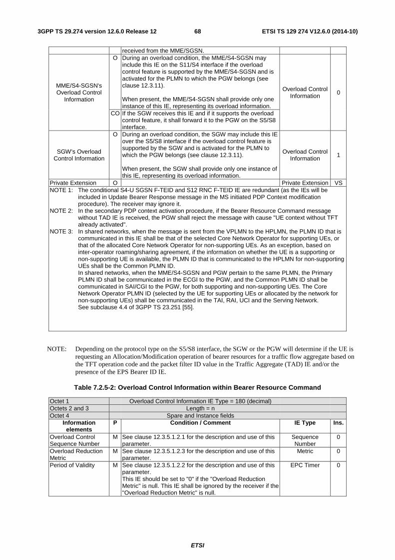
ETSI
ETSI TS 129 274 V12.6.0 (2014-10)683GPP TS 29.274 version 12.6.0 Release 12
received from the MME/SGSN.
MME/S4-SGSN's Overload Control
Information
O During an overload condition, the MME/S4-SGSN may include this IE on the S11/S4 interface if the overload control feature is supported by the MME/S4-SGSN and is activated for the PLMN to which the PGW belongs (see clause 12.3.11). When present, the MME/S4-SGSN shall provide only one instance of this IE, representing its overload information.
Overload Control Information 0
CO If the SGW receives this IE and if it supports the overload control feature, it shall forward it to the PGW on the S5/S8 interface.
SGW's Overload Control Information
O During an overload condition, the SGW may include this IE over the S5/S8 interface if the overload control feature is supported by the SGW and is activated for the PLMN to which the PGW belongs (see clause 12.3.11). When present, the SGW shall provide only one instance of this IE, representing its overload information.
Overload Control Information 1
Private Extension O Private Extension VS NOTE 1: The conditional S4-U SGSN F-TEID and S12 RNC F-TEID IE are redundant (as the IEs will be
included in Update Bearer Response message in the MS initiated PDP Context modification procedure). The receiver may ignore it.
NOTE 2: In the secondary PDP context activation procedure, if the Bearer Resource Command message without TAD IE is received, the PGW shall reject the message with cause "UE context without TFT already activated".
NOTE 3: In shared networks, when the message is sent from the VPLMN to the HPLMN, the PLMN ID that is communicated in this IE shall be that of the selected Core Network Operator for supporting UEs, or that of the allocated Core Network Operator for non-supporting UEs. As an exception, based on inter-operator roaming/sharing agreement, if the information on whether the UE is a supporting or non-supporting UE is available, the PLMN ID that is communicated to the HPLMN for non-supporting UEs shall be the Common PLMN ID. In shared networks, when the MME/S4-SGSN and PGW pertain to the same PLMN, the Primary PLMN ID shall be communicated in the ECGI to the PGW, and the Common PLMN ID shall be communicated in SAI/CGI to the PGW, for both supporting and non-supporting UEs. The Core Network Operator PLMN ID (selected by the UE for supporting UEs or allocated by the network for non-supporting UEs) shall be communicated in the TAI, RAI, UCI and the Serving Network. See subclause 4.4 of 3GPP TS 23.251 [55].
NOTE: Depending on the protocol type on the S5/S8 interface, the SGW or the PGW will determine if the UE is requesting an Allocation/Modification operation of bearer resources for a traffic flow aggregate based on the TFT operation code and the packet filter ID value in the Traffic Aggregate (TAD) IE and/or the presence of the EPS Bearer ID IE.
Table 7.2.5-2: Overload Control Information within Bearer Resource Command
Octet 1 Overload Control Information IE Type = 180 (decimal) Octets 2 and 3 Length = n Octet 4 Spare and Instance fields
Information elements
P Condition / Comment IE Type Ins.
Overload Control Sequence Number
M See clause 12.3.5.1.2.1 for the description and use of this parameter.
Sequence Number
0
Overload Reduction Metric
M See clause 12.3.5.1.2.3 for the description and use of this parameter.
Metric 0
Period of Validity M See clause 12.3.5.1.2.2 for the description and use of this parameter. This IE should be set to "0" if the "Overload Reduction Metric" is null. This IE shall be ignored by the receiver if the "Overload Reduction Metric" is null.
EPC Timer 0
ETSI
ETSI TS 129 274 V12.6.0 (2014-10)693GPP TS 29.274 version 12.6.0 Release 12
7.2.6 Bearer Resource Failure Indication
A Bearer Resource Failure Indication shall be sent by the PGW to an SGW and forwarded to the MME to indicate failure of the UE requested bearer resource allocation procedure or UE requested bearer resource modification procedure, as specified by 3GPP TS 24.301 [23].
The message shall also be sent by a PGW to an SGW and forwarded to an SGSN as part of the failure of an MS initiated PDP Context modification procedure or secondary PDP context activation procedure.
Table 7.2.6-1 specifies the presence of the IEs in the message.
Possible Cause values are specified in Table 8.4-1. Message specific cause values are:
- "Semantic error in the TAD operation".
- "Syntactic error in the TAD operation".
- "Semantic errors in packet filter(s)".
- "Syntactic errors in packet filter(s)".
- "Collision with network initiated request".
- "Service denied".
- "Bearer handling not supported".
- "UE context without TFT already activated".
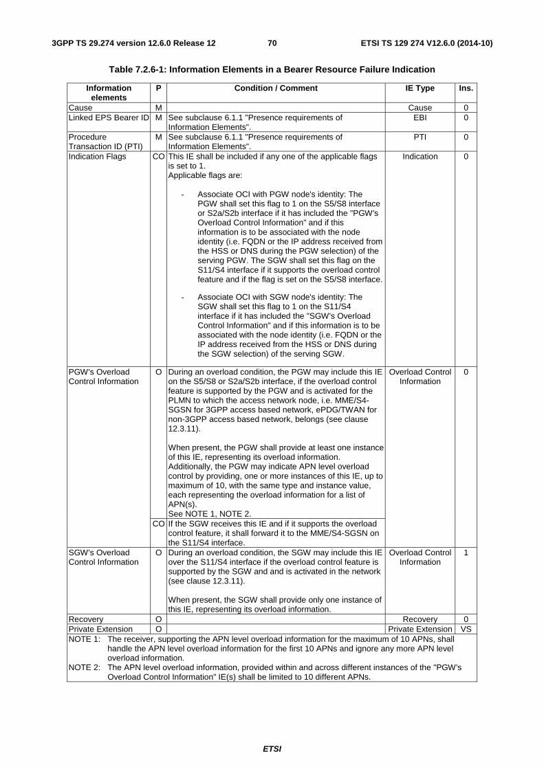
ETSI
ETSI TS 129 274 V12.6.0 (2014-10)703GPP TS 29.274 version 12.6.0 Release 12
Table 7.2.6-1: Information Elements in a Bearer Resource Failure Indication
Information elements
P Condition / Comment IE Type Ins.
Cause M Cause 0 Linked EPS Bearer ID M See subclause 6.1.1 "Presence requirements of
Information Elements". EBI 0
Procedure Transaction ID (PTI)
M See subclause 6.1.1 "Presence requirements of Information Elements".
PTI 0
Indication Flags CO This IE shall be included if any one of the applicable flags is set to 1. Applicable flags are:
- Associate OCI with PGW node's identity: The PGW shall set this flag to 1 on the S5/S8 interface or S2a/S2b interface if it has included the "PGW's Overload Control Information" and if this information is to be associated with the node identity (i.e. FQDN or the IP address received from the HSS or DNS during the PGW selection) of the serving PGW. The SGW shall set this flag on the S11/S4 interface if it supports the overload control feature and if the flag is set on the S5/S8 interface.
- Associate OCI with SGW node's identity: The SGW shall set this flag to 1 on the S11/S4 interface if it has included the "SGW's Overload Control Information" and if this information is to be associated with the node identity (i.e. FQDN or the IP address received from the HSS or DNS during the SGW selection) of the serving SGW.
Indication 0
PGW's Overload Control Information
O During an overload condition, the PGW may include this IE on the S5/S8 or S2a/S2b interface, if the overload control feature is supported by the PGW and is activated for the PLMN to which the access network node, i.e. MME/S4-SGSN for 3GPP access based network, ePDG/TWAN for non-3GPP access based network, belongs (see clause 12.3.11). When present, the PGW shall provide at least one instance of this IE, representing its overload information. Additionally, the PGW may indicate APN level overload control by providing, one or more instances of this IE, up to maximum of 10, with the same type and instance value, each representing the overload information for a list of APN(s). See NOTE 1, NOTE 2.
Overload Control Information
0
CO If the SGW receives this IE and if it supports the overload control feature, it shall forward it to the MME/S4-SGSN on the S11/S4 interface.
SGW's Overload Control Information
O During an overload condition, the SGW may include this IE over the S11/S4 interface if the overload control feature is supported by the SGW and and is activated in the network (see clause 12.3.11). When present, the SGW shall provide only one instance of this IE, representing its overload information.
Overload Control Information
1
Recovery O Recovery 0 Private Extension O Private Extension VS NOTE 1: The receiver, supporting the APN level overload information for the maximum of 10 APNs, shall
handle the APN level overload information for the first 10 APNs and ignore any more APN level overload information.
NOTE 2: The APN level overload information, provided within and across different instances of the "PGW's Overload Control Information" IE(s) shall be limited to 10 different APNs.
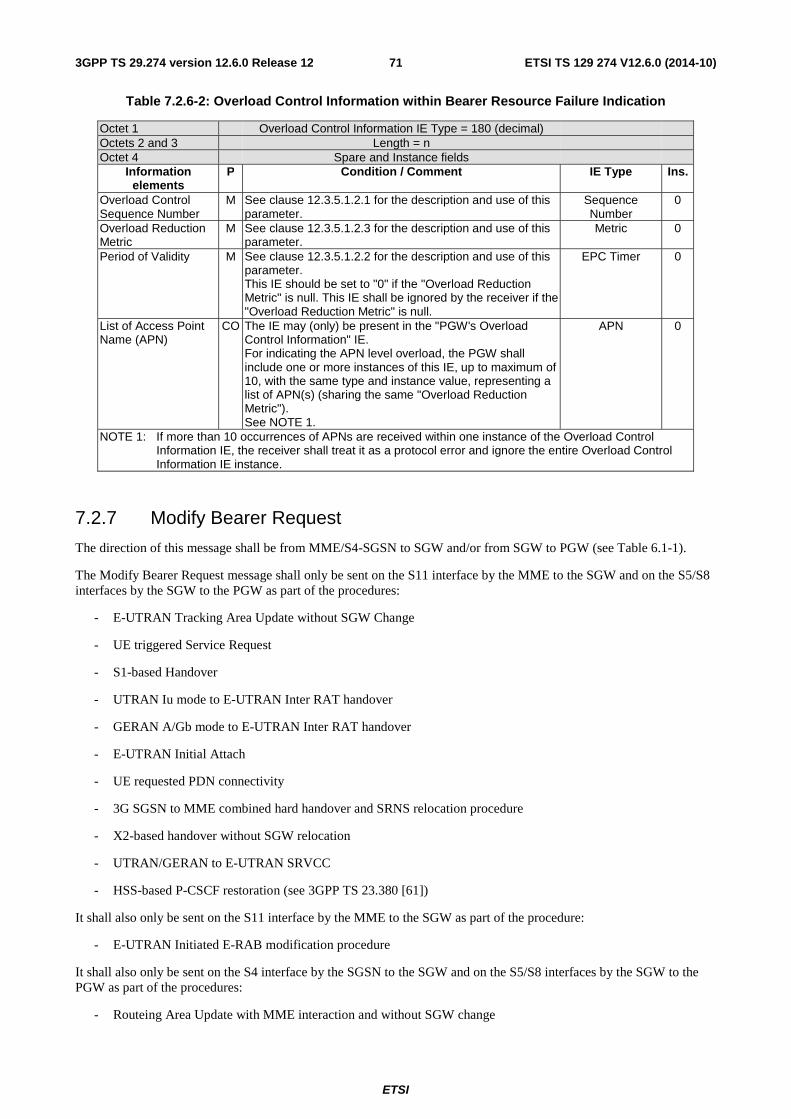
ETSI
ETSI TS 129 274 V12.6.0 (2014-10)713GPP TS 29.274 version 12.6.0 Release 12
Table 7.2.6-2: Overload Control Information within Bearer Resource Failure Indication
Octet 1 Overload Control Information IE Type = 180 (decimal) Octets 2 and 3 Length = n Octet 4 Spare and Instance fields
Information elements
P Condition / Comment IE Type Ins.
Overload Control Sequence Number
M See clause 12.3.5.1.2.1 for the description and use of this parameter.
Sequence Number
0
Overload Reduction Metric
M See clause 12.3.5.1.2.3 for the description and use of this parameter.
Metric 0
Period of Validity M See clause 12.3.5.1.2.2 for the description and use of this parameter. This IE should be set to "0" if the "Overload Reduction Metric" is null. This IE shall be ignored by the receiver if the "Overload Reduction Metric" is null.
EPC Timer 0
List of Access Point Name (APN)
CO The IE may (only) be present in the "PGW's Overload Control Information" IE. For indicating the APN level overload, the PGW shall include one or more instances of this IE, up to maximum of 10, with the same type and instance value, representing a list of APN(s) (sharing the same "Overload Reduction Metric"). See NOTE 1.
APN 0
NOTE 1: If more than 10 occurrences of APNs are received within one instance of the Overload Control Information IE, the receiver shall treat it as a protocol error and ignore the entire Overload Control Information IE instance.
7.2.7 Modify Bearer Request
The direction of this message shall be from MME/S4-SGSN to SGW and/or from SGW to PGW (see Table 6.1-1).
The Modify Bearer Request message shall only be sent on the S11 interface by the MME to the SGW and on the S5/S8 interfaces by the SGW to the PGW as part of the procedures:
- E-UTRAN Tracking Area Update without SGW Change
- UE triggered Service Request
- S1-based Handover
- UTRAN Iu mode to E-UTRAN Inter RAT handover
- GERAN A/Gb mode to E-UTRAN Inter RAT handover
- E-UTRAN Initial Attach
- UE requested PDN connectivity
- 3G SGSN to MME combined hard handover and SRNS relocation procedure
- X2-based handover without SGW relocation
- UTRAN/GERAN to E-UTRAN SRVCC
- HSS-based P-CSCF restoration (see 3GPP TS 23.380 [61])
It shall also only be sent on the S11 interface by the MME to the SGW as part of the procedure:
- E-UTRAN Initiated E-RAB modification procedure
It shall also only be sent on the S4 interface by the SGSN to the SGW and on the S5/S8 interfaces by the SGW to the PGW as part of the procedures:
- Routeing Area Update with MME interaction and without SGW change
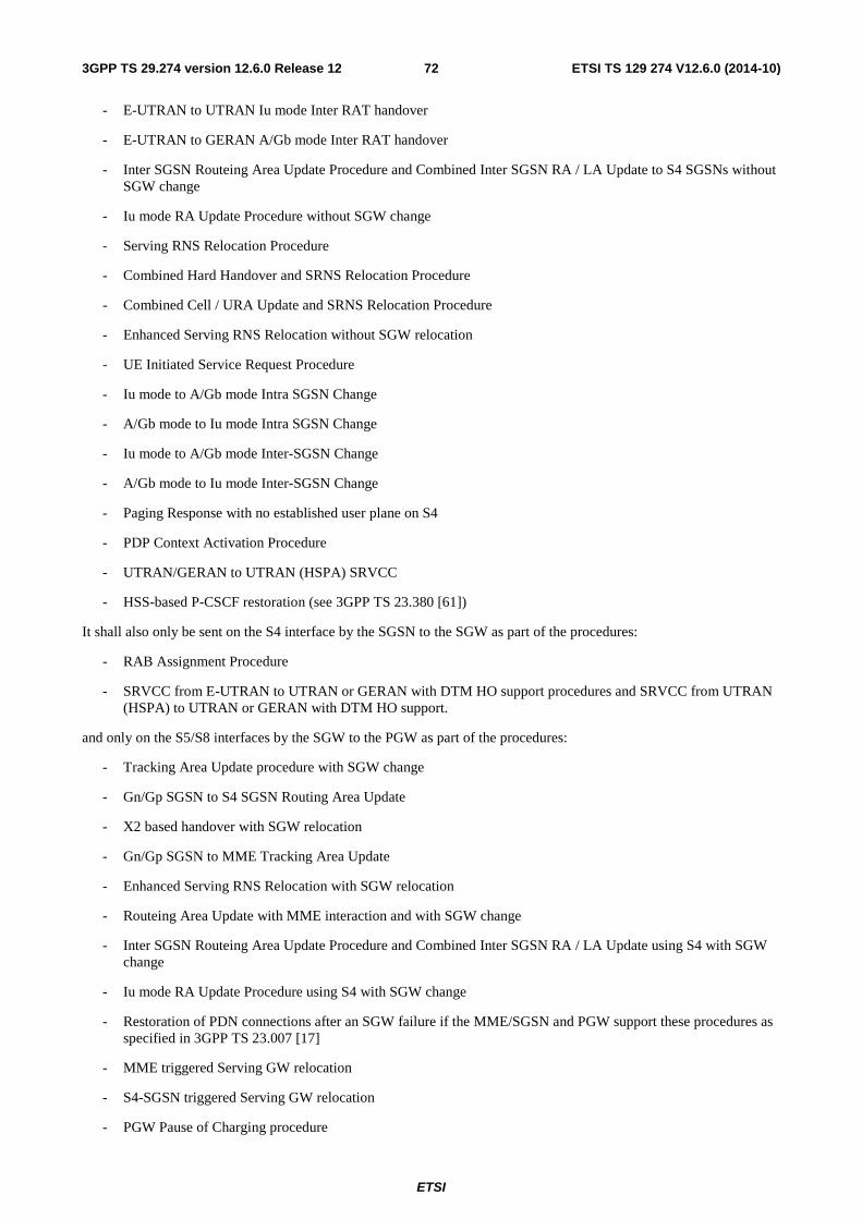
ETSI
ETSI TS 129 274 V12.6.0 (2014-10)723GPP TS 29.274 version 12.6.0 Release 12
- E-UTRAN to UTRAN Iu mode Inter RAT handover
- E-UTRAN to GERAN A/Gb mode Inter RAT handover
- Inter SGSN Routeing Area Update Procedure and Combined Inter SGSN RA / LA Update to S4 SGSNs without SGW change
- Iu mode RA Update Procedure without SGW change
- Serving RNS Relocation Procedure
- Combined Hard Handover and SRNS Relocation Procedure
- Combined Cell / URA Update and SRNS Relocation Procedure
- Enhanced Serving RNS Relocation without SGW relocation
- UE Initiated Service Request Procedure
- Iu mode to A/Gb mode Intra SGSN Change
- A/Gb mode to Iu mode Intra SGSN Change
- Iu mode to A/Gb mode Inter-SGSN Change
- A/Gb mode to Iu mode Inter-SGSN Change
- Paging Response with no established user plane on S4
- PDP Context Activation Procedure
- UTRAN/GERAN to UTRAN (HSPA) SRVCC
- HSS-based P-CSCF restoration (see 3GPP TS 23.380 [61])
It shall also only be sent on the S4 interface by the SGSN to the SGW as part of the procedures:
- RAB Assignment Procedure
- SRVCC from E-UTRAN to UTRAN or GERAN with DTM HO support procedures and SRVCC from UTRAN (HSPA) to UTRAN or GERAN with DTM HO support.
and only on the S5/S8 interfaces by the SGW to the PGW as part of the procedures:
- Tracking Area Update procedure with SGW change
- Gn/Gp SGSN to S4 SGSN Routing Area Update
- X2 based handover with SGW relocation
- Gn/Gp SGSN to MME Tracking Area Update
- Enhanced Serving RNS Relocation with SGW relocation
- Routeing Area Update with MME interaction and with SGW change
- Inter SGSN Routeing Area Update Procedure and Combined Inter SGSN RA / LA Update using S4 with SGW change
- Iu mode RA Update Procedure using S4 with SGW change
- Restoration of PDN connections after an SGW failure if the MME/SGSN and PGW support these procedures as specified in 3GPP TS 23.007 [17]
- MME triggered Serving GW relocation
- S4-SGSN triggered Serving GW relocation
- PGW Pause of Charging procedure

ETSI
ETSI TS 129 274 V12.6.0 (2014-10)733GPP TS 29.274 version 12.6.0 Release 12
and on the S2b interface by the ePDG to the PGW as part of the procedures:
- UE initiated IPsec tunnel update procedure
If the optional network triggered service restoration feature is supported by the MME, SGSN and SGW, then the Modify Bearer Request message shall also be sent as part of the network triggered service restoration procedure with ISR during an intra MME TAU and an intra S4-SGSN RAU procedure for UEs that had ISR active before either the MME or the S4-SGSN has restarted, as specified in 3GPP TS 23.007 [17]:
- on the S11 interface by the MME to the SGW, if the MME detected that the ISR associated S4-SGSN has restarted and UE performs a TAU procedure;
- on the S4 interface by the S4-SGSN to the SGW, if the S4-SGSN detected that the ISR associated MME has restarted and UE performs a RAU procedure.
This message can be used as an implicit resume of the suspended bearers in the SGW and in the PGW (see 3GPP TS 23.216 [43] sections 6.2.2.1 and 6.3.2.1, 3GPP TS 23.272 [21] sections 6.3, 6.5 and 7.4). A Modify Bearer Request used as an implicit resume can contain zero or more IE(s), depending on the conditions of presence of the IEs specified in table 7.2.7-1. The PGW should not consider a Modify Bearer Request with zero IE as an error.
The Modify Bearer Request message may also be sent in the following cases from the S4-SGSN to the SGW/PGW to report a change of Serving Network, User CSG Information or/and UE Time Zone which occured during a previous RAU procedure without SGSN change but which has not been reported yet to the SGW/PGW:
- during a Service Request procedure to establish data radio bearers for the corresponding PDP context for a UE in UTRAN with an existing S4-U tunnel;
- when the SGSN receives an uplink LLC PDU for user data or any valid LLC frame serving as a paging response from a UE in GERAN with an existing S4-U tunnel.
The Modify Bearer Request message may also be sent in the following cases from the S4-SGSN to the SGW/PGW to report a change of User Location Information which occured during a previous RAU procedure without SGSN change but which has not been reported yet to the SGW/PGW, if the S4-SGSN is configured to defer the reporting of ULI change until a RAB/user plane is established:
- during a Service Request procedure to establish data radio bearers for the corresponding PDP context for a UE in UTRAN with an existing S4-U tunnel;
- when the SGSN receives an uplink LLC PDU for user data or any valid LLC frame serving as a paging response for a UE in GERAN with an existing S4-U tunnel.
NOTE 1: the S4-SGSN can alternatively send a Change Notification Request message in the above cases, if no other information which requires the sending of a Modify Bearer Request, needs to be reported to the PGW.
When requesting the PGW to pause or unpause charging for a PDN connection, the SGW shall wait for the PGW acknowledgement (i.e. Modify Bearer Response) before sending a new pause or unpause request.
NOTE 2: this ensures that the PGW always act per the most recent SGW request in particular in scenarios where the SGW would need to request the PGW to pause and unpause charging in a row (or vice-versa) and the the Modify Bearer Request messages would arrive out of order at the PGW.
Upon receipt of a request from the PGW/PCRF in a message other than Create Bearer Request and Update Bearer Request to report changes of UE presence in a Presence Reporting Area, the MME/S4-SGSN shall immediately send a Modify Bearer Request message or a Change Notification Request message to report to the PGW whether the UE is inside or outside the Presence Reporting Area.
The MME/S4-SGSN shall also send a Modify Bearer Request message or a Change Notification Request message to report any subsequent change of UE presence in the Presence Reporting Area, as specified in 3GPP TS 23.401 [3] and 3GPP TS 23.060 [35].
Upon receipt of a Modify Bearer Request message that includes the Presence Reporting Area Information from the MME/S4-SGSN, the SGW shall send a Modify Bearer Request message on the S5/S8 interface if any of the following condition is met:
- ISR is not active;

ETSI
ETSI TS 129 274 V12.6.0 (2014-10)743GPP TS 29.274 version 12.6.0 Release 12
- ISR is active, and the RAT Type has changed since last reported or the CPRAI flag has been set to 1.
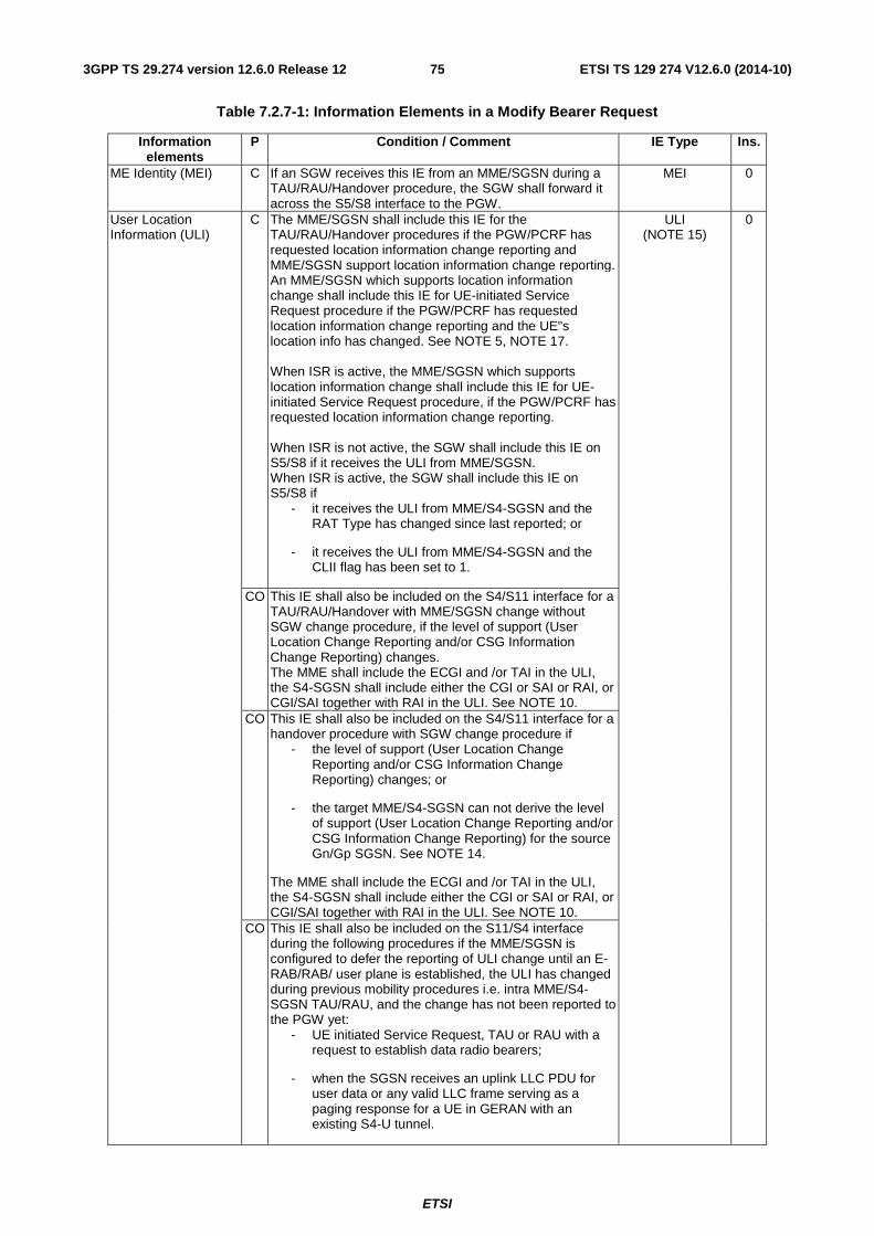
ETSI
ETSI TS 129 274 V12.6.0 (2014-10)753GPP TS 29.274 version 12.6.0 Release 12
Table 7.2.7-1: Information Elements in a Modify Bearer Request
Information elements
P Condition / Comment IE Type Ins.
ME Identity (MEI) C If an SGW receives this IE from an MME/SGSN during a TAU/RAU/Handover procedure, the SGW shall forward it across the S5/S8 interface to the PGW.
MEI 0
User Location Information (ULI)
C The MME/SGSN shall include this IE for the TAU/RAU/Handover procedures if the PGW/PCRF has requested location information change reporting and MME/SGSN support location information change reporting. An MME/SGSN which supports location information change shall include this IE for UE-initiated Service Request procedure if the PGW/PCRF has requested location information change reporting and the UE"s location info has changed. See NOTE 5, NOTE 17. When ISR is active, the MME/SGSN which supports location information change shall include this IE for UE-initiated Service Request procedure, if the PGW/PCRF has requested location information change reporting. When ISR is not active, the SGW shall include this IE on S5/S8 if it receives the ULI from MME/SGSN. When ISR is active, the SGW shall include this IE on S5/S8 if
- it receives the ULI from MME/S4-SGSN and the RAT Type has changed since last reported; or
- it receives the ULI from MME/S4-SGSN and the CLII flag has been set to 1.
ULI (NOTE 15)
0
CO This IE shall also be included on the S4/S11 interface for a TAU/RAU/Handover with MME/SGSN change without SGW change procedure, if the level of support (User Location Change Reporting and/or CSG Information Change Reporting) changes. The MME shall include the ECGI and /or TAI in the ULI, the S4-SGSN shall include either the CGI or SAI or RAI, or CGI/SAI together with RAI in the ULI. See NOTE 10.
CO This IE shall also be included on the S4/S11 interface for a handover procedure with SGW change procedure if
- the level of support (User Location Change Reporting and/or CSG Information Change Reporting) changes; or
- the target MME/S4-SGSN can not derive the level of support (User Location Change Reporting and/or CSG Information Change Reporting) for the source Gn/Gp SGSN. See NOTE 14.
The MME shall include the ECGI and /or TAI in the ULI, the S4-SGSN shall include either the CGI or SAI or RAI, or CGI/SAI together with RAI in the ULI. See NOTE 10.
CO This IE shall also be included on the S11/S4 interface during the following procedures if the MME/SGSN is configured to defer the reporting of ULI change until an E-RAB/RAB/ user plane is established, the ULI has changed during previous mobility procedures i.e. intra MME/S4-SGSN TAU/RAU, and the change has not been reported to the PGW yet:
- UE initiated Service Request, TAU or RAU with a request to establish data radio bearers;
- when the SGSN receives an uplink LLC PDU for user data or any valid LLC frame serving as a paging response for a UE in GERAN with an existing S4-U tunnel.
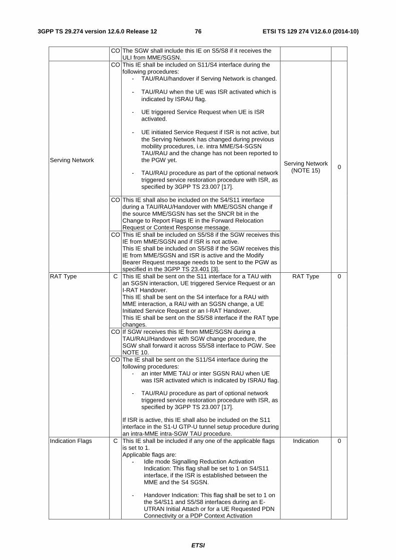
ETSI
ETSI TS 129 274 V12.6.0 (2014-10)763GPP TS 29.274 version 12.6.0 Release 12
CO The SGW shall include this IE on S5/S8 if it receives the ULI from MME/SGSN.
Serving Network
CO This IE shall be included on S11/S4 interface during the following procedures:
- TAU/RAU/handover if Serving Network is changed.
- TAU/RAU when the UE was ISR activated which is indicated by ISRAU flag.
- UE triggered Service Request when UE is ISR activated.
- UE initiated Service Request if ISR is not active, but the Serving Network has changed during previous mobility procedures, i.e. intra MME/S4-SGSN TAU/RAU and the change has not been reported to the PGW yet.
- TAU/RAU procedure as part of the optional network triggered service restoration procedure with ISR, as specified by 3GPP TS 23.007 [17].
Serving Network (NOTE 15) 0
CO This IE shall also be included on the S4/S11 interface during a TAU/RAU/Handover with MME/SGSN change if the source MME/SGSN has set the SNCR bit in the Change to Report Flags IE in the Forward Relocation Request or Context Response message.
CO This IE shall be included on S5/S8 if the SGW receives this IE from MME/SGSN and if ISR is not active. This IE shall be included on S5/S8 if the SGW receives this IE from MME/SGSN and ISR is active and the Modify Bearer Request message needs to be sent to the PGW as specified in the 3GPP TS 23.401 [3].
RAT Type C This IE shall be sent on the S11 interface for a TAU with an SGSN interaction, UE triggered Service Request or an I-RAT Handover. This IE shall be sent on the S4 interface for a RAU with MME interaction, a RAU with an SGSN change, a UE Initiated Service Request or an I-RAT Handover. This IE shall be sent on the S5/S8 interface if the RAT type changes.
RAT Type 0
CO If SGW receives this IE from MME/SGSN during a TAU/RAU/Handover with SGW change procedure, the SGW shall forward it across S5/S8 interface to PGW. See NOTE 10.
CO The IE shall be sent on the S11/S4 interface during the following procedures:
- an inter MME TAU or inter SGSN RAU when UE was ISR activated which is indicated by ISRAU flag.
- TAU/RAU procedure as part of optional network triggered service restoration procedure with ISR, as specified by 3GPP TS 23.007 [17].
If ISR is active, this IE shall also be included on the S11 interface in the S1-U GTP-U tunnel setup procedure during an intra-MME intra-SGW TAU procedure.
Indication Flags C This IE shall be included if any one of the applicable flags is set to 1. Applicable flags are:
- Idle mode Signalling Reduction Activation Indication: This flag shall be set to 1 on S4/S11 interface, if the ISR is established between the MME and the S4 SGSN.
- Handover Indication: This flag shall be set to 1 on the S4/S11 and S5/S8 interfaces during an E-UTRAN Initial Attach or for a UE Requested PDN Connectivity or a PDP Context Activation
Indication 0
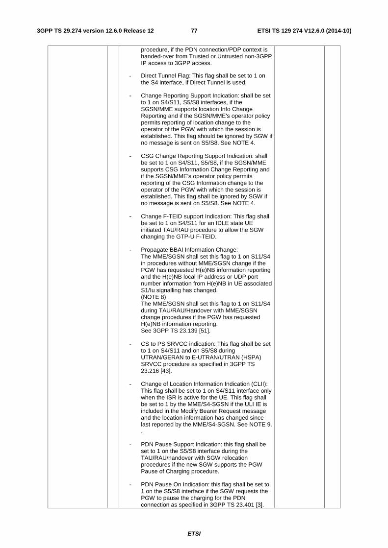
ETSI
ETSI TS 129 274 V12.6.0 (2014-10)773GPP TS 29.274 version 12.6.0 Release 12
procedure, if the PDN connection/PDP context is handed-over from Trusted or Untrusted non-3GPP IP access to 3GPP access.
- Direct Tunnel Flag: This flag shall be set to 1 on the S4 interface, if Direct Tunnel is used.
- Change Reporting Support Indication: shall be set to 1 on S4/S11, S5/S8 interfaces, if the SGSN/MME supports location Info Change Reporting and if the SGSN/MME's operator policy permits reporting of location change to the operator of the PGW with which the session is established. This flag should be ignored by SGW if no message is sent on S5/S8. See NOTE 4.
- CSG Change Reporting Support Indication: shall be set to 1 on S4/S11, S5/S8, if the SGSN/MME supports CSG Information Change Reporting and if the SGSN/MME's operator policy permits reporting of the CSG Information change to the operator of the PGW with which the session is established. This flag shall be ignored by SGW if no message is sent on S5/S8. See NOTE 4.
- Change F-TEID support Indication: This flag shall be set to 1 on S4/S11 for an IDLE state UE initiated TAU/RAU procedure to allow the SGW changing the GTP-U F-TEID.
- Propagate BBAI Information Change: The MME/SGSN shall set this flag to 1 on S11/S4 in procedures without MME/SGSN change if the PGW has requested H(e)NB information reporting and the H(e)NB local IP address or UDP port number information from H(e)NB in UE associated S1/Iu signalling has changed. (NOTE 8) The MME/SGSN shall set this flag to 1 on S11/S4 during TAU/RAU/Handover with MME/SGSN change procedures if the PGW has requested H(e)NB information reporting. See 3GPP TS 23.139 [51].
- CS to PS SRVCC indication: This flag shall be set to 1 on S4/S11 and on S5/S8 during UTRAN/GERAN to E-UTRAN/UTRAN (HSPA) SRVCC procedure as specified in 3GPP TS 23.216 [43].
- Change of Location Information Indication (CLII): This flag shall be set to 1 on S4/S11 interface only when the ISR is active for the UE. This flag shall be set to 1 by the MME/S4-SGSN if the ULI IE is included in the Modify Bearer Request message and the location information has changed since last reported by the MME/S4-SGSN. See NOTE 9. .
- PDN Pause Support Indication: this flag shall be set to 1 on the S5/S8 interface during the TAU/RAU/handover with SGW relocation procedures if the new SGW supports the PGW Pause of Charging procedure.
- PDN Pause On Indication: this flag shall be set to 1 on the S5/S8 interface if the SGW requests the PGW to pause the charging for the PDN connection as specified in 3GPP TS 23.401 [3].
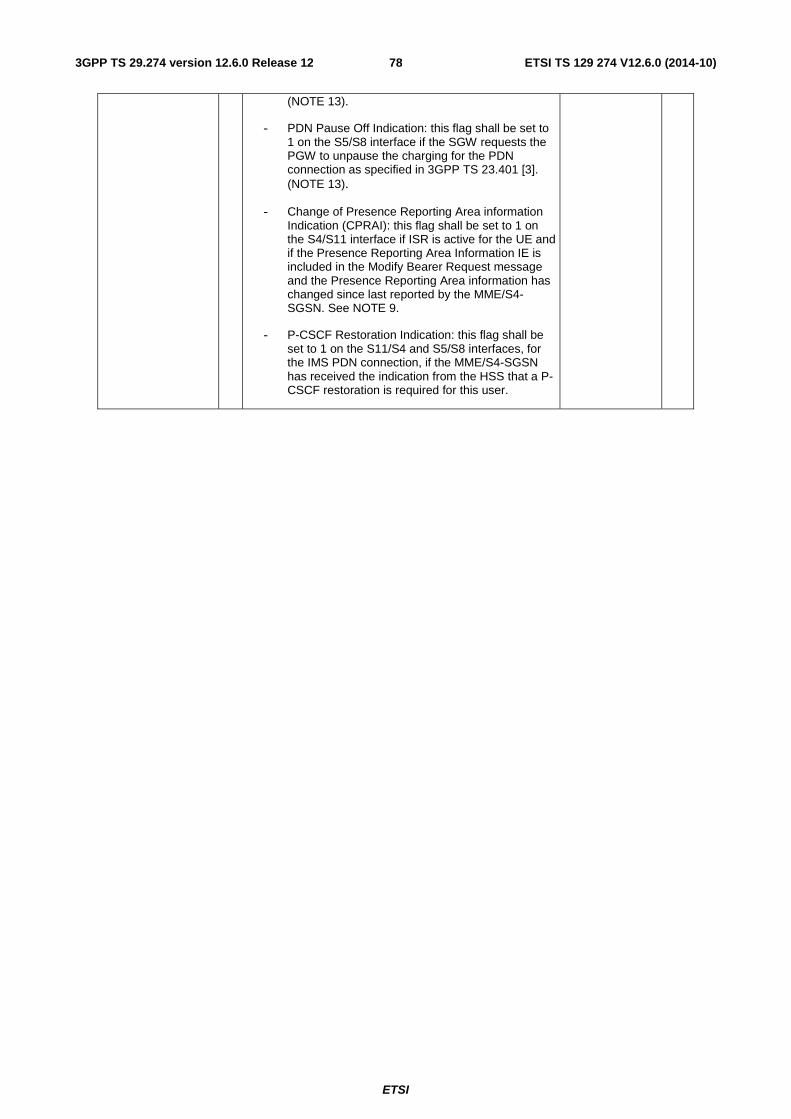
ETSI
ETSI TS 129 274 V12.6.0 (2014-10)783GPP TS 29.274 version 12.6.0 Release 12
(NOTE 13).
- PDN Pause Off Indication: this flag shall be set to 1 on the S5/S8 interface if the SGW requests the PGW to unpause the charging for the PDN connection as specified in 3GPP TS 23.401 [3]. (NOTE 13).
- Change of Presence Reporting Area information Indication (CPRAI): this flag shall be set to 1 on the S4/S11 interface if ISR is active for the UE and if the Presence Reporting Area Information IE is included in the Modify Bearer Request message and the Presence Reporting Area information has changed since last reported by the MME/S4-SGSN. See NOTE 9.
- P-CSCF Restoration Indication: this flag shall be set to 1 on the S11/S4 and S5/S8 interfaces, for the IMS PDN connection, if the MME/S4-SGSN has received the indication from the HSS that a P-CSCF restoration is required for this user.
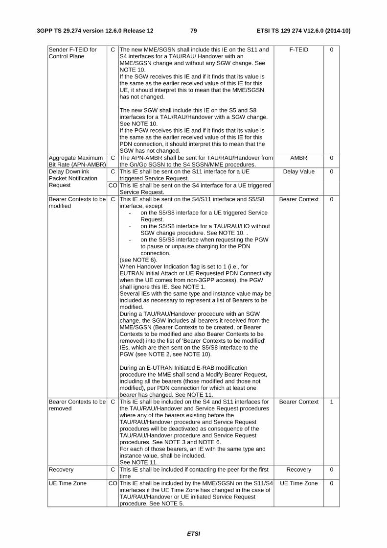
ETSI
ETSI TS 129 274 V12.6.0 (2014-10)793GPP TS 29.274 version 12.6.0 Release 12
Sender F-TEID for Control Plane
C The new MME/SGSN shall include this IE on the S11 and S4 interfaces for a TAU/RAU/ Handover with an MME/SGSN change and without any SGW change. See NOTE 10. If the SGW receives this IE and if it finds that its value is the same as the earlier received value of this IE for this UE, it should interpret this to mean that the MME/SGSN has not changed. The new SGW shall include this IE on the S5 and S8 interfaces for a TAU/RAU/Handover with a SGW change. See NOTE 10. If the PGW receives this IE and if it finds that its value is the same as the earlier received value of this IE for this PDN connection, it should interpret this to mean that the SGW has not changed.
F-TEID 0
Aggregate Maximum Bit Rate (APN-AMBR)
C The APN-AMBR shall be sent for TAU/RAU/Handover from the Gn/Gp SGSN to the S4 SGSN/MME procedures.
AMBR 0
Delay Downlink Packet Notification Request
C This IE shall be sent on the S11 interface for a UE triggered Service Request.
Delay Value 0
CO This IE shall be sent on the S4 interface for a UE triggered Service Request.
Bearer Contexts to be modified
C This IE shall be sent on the S4/S11 interface and S5/S8 interface, except
- on the S5/S8 interface for a UE triggered Service Request.
- on the S5/S8 interface for a TAU/RAU/HO without SGW change procedure. See NOTE 10. .
- on the S5/S8 interface when requesting the PGW to pause or unpause charging for the PDN connection.
(see NOTE 6). When Handover Indication flag is set to 1 (i.e., for EUTRAN Initial Attach or UE Requested PDN Connectivity when the UE comes from non-3GPP access), the PGW shall ignore this IE. See NOTE 1. Several IEs with the same type and instance value may be included as necessary to represent a list of Bearers to be modified. During a TAU/RAU/Handover procedure with an SGW change, the SGW includes all bearers it received from the MME/SGSN (Bearer Contexts to be created, or Bearer Contexts to be modified and also Bearer Contexts to be removed) into the list of 'Bearer Contexts to be modified' IEs, which are then sent on the S5/S8 interface to the PGW (see NOTE 2, see NOTE 10). During an E-UTRAN Initiated E-RAB modification procedure the MME shall send a Modify Bearer Request, including all the bearers (those modified and those not modified), per PDN connection for which at least one bearer has changed. See NOTE 11.
Bearer Context 0
Bearer Contexts to be removed
C This IE shall be included on the S4 and S11 interfaces for the TAU/RAU/Handover and Service Request procedures where any of the bearers existing before the TAU/RAU/Handover procedure and Service Request procedures will be deactivated as consequence of the TAU/RAU/Handover procedure and Service Request procedures. See NOTE 3 and NOTE 6. For each of those bearers, an IE with the same type and instance value, shall be included. See NOTE 11.
Bearer Context 1
Recovery C This IE shall be included if contacting the peer for the first time
Recovery 0
UE Time Zone CO This IE shall be included by the MME/SGSN on the S11/S4 interfaces if the UE Time Zone has changed in the case of TAU/RAU/Handover or UE initiated Service Request procedure. See NOTE 5.
UE Time Zone 0
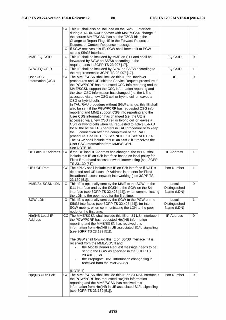
ETSI
ETSI TS 129 274 V12.6.0 (2014-10)803GPP TS 29.274 version 12.6.0 Release 12
CO This IE shall also be included on the S4/S11 interface during a TAU/RAU/Handover with MME/SGSN change if the source MME/SGSN has set the TZCR bit in the Change to Report Flags IE in the Forward Relocation Request or Context Response message.
C If SGW receives this IE, SGW shall forward it to PGW across S5/S8 interface.
MME-FQ-CSID C This IE shall be included by MME on S11 and shall be forwarded by SGW on S5/S8 according to the requirements in 3GPP TS 23.007 [17].
FQ-CSID 0
SGW-FQ-CSID C This IE shall be included by SGW on S5/S8 according to the requirements in 3GPP TS 23.007 [17].
FQ-CSID 1
User CSG Information (UCI)
CO The MME/SGSN shall include this IE for Handover procedures and UE-initiated Service Request procedure if the PGW/PCRF has requested CSG Info reporting and the MME/SGSN support the CSG information reporting and the User CSG information has changed (i.e. the UE is accessed via a new CSG cell or hybrid cell or leaves a CSG or hybrid cell). In TAU/RAU procedure without SGW change, this IE shall also be sent if the PGW/PCRF has requested CSG info reporting and MME support CSG info reporting and the User CSG information has changed (i.e. the UE is accessed via a new CSG cell or hybrid cell or leaves a CSG or hybrid cell) when UE requested to active E-RAB for all the active EPS bearers in TAU procedure or to keep the Iu connection after the completion of the RAU procedure. See NOTE 5. See NOTE 10. See NOTE 16. The SGW shall include this IE on S5/S8 if it receives the User CSG Information from MME/SGSN. See NOTE 15.
UCI 0
UE Local IP Address CO If the UE local IP Address has changed, the ePDG shall include this IE on S2b interface based on local policy for Fixed Broadband access network interworking (see 3GPP TS 23.139 [51]).
IP Address 1
UE UDP Port CO The ePDG shall include this IE on S2b interface if NAT is detected and UE Local IP Address is present for Fixed Broadband access network interworking (see 3GPP TS 23.139 [51]).
Port Number 1
MME/S4-SGSN LDN O This IE is optionally sent by the MME to the SGW on the S11 interface and by the SGSN to the SGW on the S4 interface (see 3GPP TS 32.423 [44]), when communicating the LDN to the peer node for the first time.
Local Distinguished Name (LDN)
0
SGW LDN O This IE is optionally sent by the SGW to the PGW on the S5/S8 interfaces (see 3GPP TS 32.423 [44]), for inter-SGW mobity, when communicating the LDN to the peer node for the first time.
Local Distinguished Name (LDN)
1
H(e)NB Local IP Address
CO The MME/SGSN shall include this IE on S11/S4 interface if the PGW/PCRF has requested H(e)NB information reporting and the MME/SGSN has received this information from H(e)NB in UE associated S1/Iu signalling (see 3GPP TS 23.139 [51]). The SGW shall forward this IE on S5/S8 interface if it is received from the MME/SGSN and
- the Modify Bearer Request message needs to be sent to the PGW as specified in the 3GPP TS 23.401 [3]; or
- the Propagate BBAI information change flag is received from the MME/SGSN.
(NOTE 7)
IP Address 0
H(e)NB UDP Port CO The MME/SGSN shall include this IE on S11/S4 interface if the PGW/PCRF has requested H(e)NB information reporting and the MME/SGSN has received this information from H(e)NB in UE associated S1/Iu signalling (see 3GPP TS 23.139 [51]).
Port Number 0
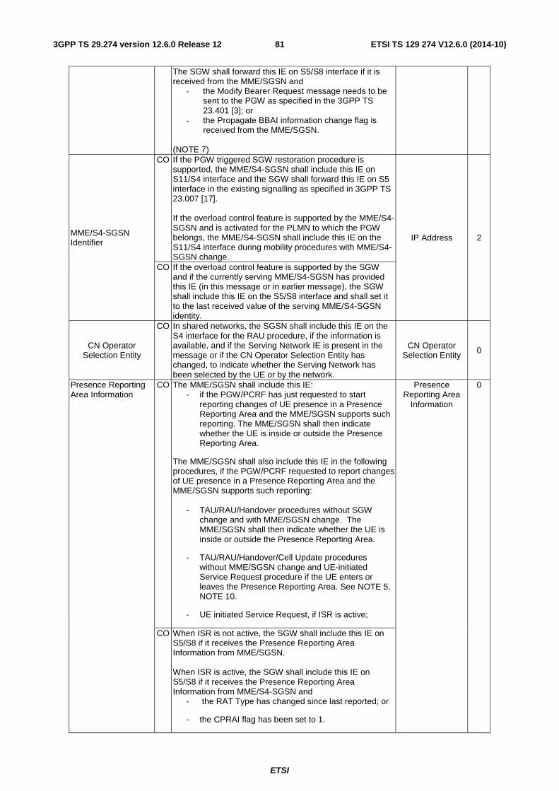
ETSI
ETSI TS 129 274 V12.6.0 (2014-10)813GPP TS 29.274 version 12.6.0 Release 12
The SGW shall forward this IE on S5/S8 interface if it is received from the MME/SGSN and
- the Modify Bearer Request message needs to be sent to the PGW as specified in the 3GPP TS 23.401 [3]; or
- the Propagate BBAI information change flag is received from the MME/SGSN.
(NOTE 7)
MME/S4-SGSN Identifier
CO If the PGW triggered SGW restoration procedure is supported, the MME/S4-SGSN shall include this IE on S11/S4 interface and the SGW shall forward this IE on S5 interface in the existing signalling as specified in 3GPP TS 23.007 [17]. If the overload control feature is supported by the MME/S4-SGSN and is activated for the PLMN to which the PGW belongs, the MME/S4-SGSN shall include this IE on the S11/S4 interface during mobility procedures with MME/S4-SGSN change.
IP Address 2
CO If the overload control feature is supported by the SGW and if the currently serving MME/S4-SGSN has provided this IE (in this message or in earlier message), the SGW shall include this IE on the S5/S8 interface and shall set it to the last received value of the serving MME/S4-SGSN identity.
CN Operator Selection Entity
CO In shared networks, the SGSN shall include this IE on the S4 interface for the RAU procedure, if the information is available, and if the Serving Network IE is present in the message or if the CN Operator Selection Entity has changed, to indicate whether the Serving Network has been selected by the UE or by the network.
CN Operator Selection Entity 0
Presence Reporting Area Information
CO The MME/SGSN shall include this IE: - if the PGW/PCRF has just requested to start
reporting changes of UE presence in a Presence Reporting Area and the MME/SGSN supports such reporting. The MME/SGSN shall then indicate whether the UE is inside or outside the Presence Reporting Area.
The MME/SGSN shall also include this IE in the following procedures, if the PGW/PCRF requested to report changes of UE presence in a Presence Reporting Area and the MME/SGSN supports such reporting:
- TAU/RAU/Handover procedures without SGW change and with MME/SGSN change. The MME/SGSN shall then indicate whether the UE is inside or outside the Presence Reporting Area.
- TAU/RAU/Handover/Cell Update procedures without MME/SGSN change and UE-initiated Service Request procedure if the UE enters or leaves the Presence Reporting Area. See NOTE 5, NOTE 10.
- UE initiated Service Request, if ISR is active;
Presence Reporting Area
Information
0
CO When ISR is not active, the SGW shall include this IE on S5/S8 if it receives the Presence Reporting Area Information from MME/SGSN. When ISR is active, the SGW shall include this IE on S5/S8 if it receives the Presence Reporting Area Information from MME/S4-SGSN and
- the RAT Type has changed since last reported; or
- the CPRAI flag has been set to 1.
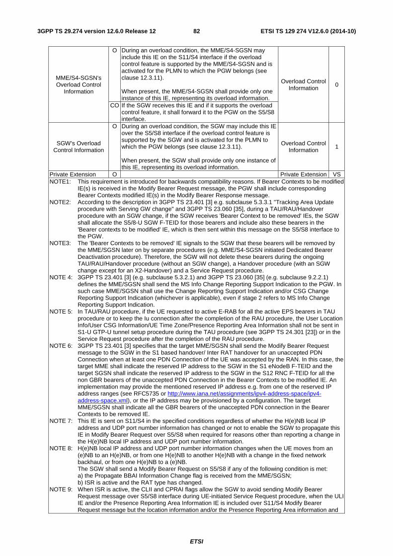
ETSI
ETSI TS 129 274 V12.6.0 (2014-10)823GPP TS 29.274 version 12.6.0 Release 12
MME/S4-SGSN's Overload Control
Information
O During an overload condition, the MME/S4-SGSN may include this IE on the S11/S4 interface if the overload control feature is supported by the MME/S4-SGSN and is activated for the PLMN to which the PGW belongs (see clause 12.3.11). When present, the MME/S4-SGSN shall provide only one instance of this IE, representing its overload information.
Overload Control Information 0
CO If the SGW receives this IE and if it supports the overload control feature, it shall forward it to the PGW on the S5/S8 interface.
SGW's Overload Control Information
O During an overload condition, the SGW may include this IE over the S5/S8 interface if the overload control feature is supported by the SGW and is activated for the PLMN to which the PGW belongs (see clause 12.3.11). When present, the SGW shall provide only one instance of this IE, representing its overload information.
Overload Control Information 1
Private Extension O Private Extension VS NOTE1: This requirement is introduced for backwards compatibility reasons. If Bearer Contexts to be modified
IE(s) is received in the Modify Bearer Request message, the PGW shall include corresponding Bearer Contexts modified IE(s) in the Modify Bearer Response message.
NOTE2: According to the description in 3GPP TS 23.401 [3] e.g. subclause 5.3.3.1 "Tracking Area Update procedure with Serving GW change" and 3GPP TS 23.060 [35], during a TAU/RAU/Handover procedure with an SGW change, if the SGW receives 'Bearer Context to be removed' IEs, the SGW shall allocate the S5/8-U SGW F-TEID for those bearers and include also these bearers in the 'Bearer contexts to be modified' IE, which is then sent within this message on the S5/S8 interface to the PGW.
NOTE3: The 'Bearer Contexts to be removed' IE signals to the SGW that these bearers will be removed by the MME/SGSN later on by separate procedures (e.g. MME/S4-SGSN initiated Dedicated Bearer Deactivation procedure). Therefore, the SGW will not delete these bearers during the ongoing TAU/RAU/Handover procedure (without an SGW change), a Handover procedure (with an SGW change except for an X2-Handover) and a Service Request procedure.
NOTE 4: 3GPP TS 23.401 [3] (e.g. subclause 5.3.2.1) and 3GPP TS 23.060 [35] (e.g. subclause 9.2.2.1) defines the MME/SGSN shall send the MS Info Change Reporting Support Indication to the PGW. In such case MME/SGSN shall use the Change Reporting Support Indication and/or CSG Change Reporting Support Indication (whichever is applicable), even if stage 2 refers to MS Info Change Reporting Support Indication.
NOTE 5: In TAU/RAU procedure, if the UE requested to active E-RAB for all the active EPS bearers in TAU procedure or to keep the Iu connection after the completion of the RAU procedure, the User Location Info/User CSG Information/UE Time Zone/Presence Reporting Area Information shall not be sent in S1-U GTP-U tunnel setup procedure during the TAU procedure (see 3GPP TS 24.301 [23]) or in the Service Request procedure after the completion of the RAU procedure.
NOTE 6: 3GPP TS 23.401 [3] specifies that the target MME/SGSN shall send the Modify Bearer Request message to the SGW in the S1 based handover/ Inter RAT handover for an unaccepted PDN Connection when at least one PDN Connection of the UE was accepted by the RAN. In this case, the target MME shall indicate the reserved IP address to the SGW in the S1 eNodeB F-TEID and the target SGSN shall indicate the reserved IP address to the SGW in the S12 RNC F-TEID for all the non GBR bearers of the unaccepted PDN Connection in the Bearer Contexts to be modified IE. An implementation may provide the mentioned reserved IP address e.g. from one of the reserved IP address ranges (see RFC5735 or http://www.iana.net/assignments/ipv4-address-space/ipv4-address-space.xml), or the IP address may be provisioned by a configuration. The target MME/SGSN shall indicate all the GBR bearers of the unaccepted PDN connection in the Bearer Contexts to be removed IE.
NOTE 7: This IE is sent on S11/S4 in the specified conditions regardless of whether the H(e)NB local IP address and UDP port number information has changed or not to enable the SGW to propagate this IE in Modify Bearer Request over S5/S8 when required for reasons other than reporting a change in the H(e)NB local IP address and UDP port number information.
NOTE 8: H(e)NB local IP address and UDP port number information changes when the UE moves from an (e)NB to an H(e)NB, or from one H(e)NB to another H(e)NB with a change in the fixed network backhaul, or from one H(e)NB to a (e)NB. The SGW shall send a Modify Bearer Request on S5/S8 if any of the following condition is met: a) the Propagate BBAI Information Change flag is received from the MME/SGSN; b) ISR is active and the RAT type has changed.
NOTE 9: When ISR is active, the CLII and CPRAI flags allow the SGW to avoid sending Modify Bearer Request message over S5/S8 interface during UE-initiated Service Request procedure, when the ULI IE and/or the Presence Reporting Area Information IE is included over S11/S4 Modify Bearer Request message but the location information and/or the Presence Reporting Area information and
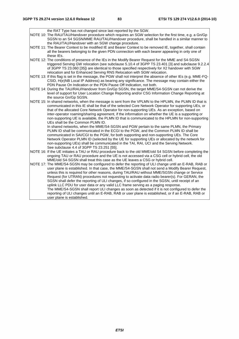
ETSI
ETSI TS 129 274 V12.6.0 (2014-10)833GPP TS 29.274 version 12.6.0 Release 12
the RAT Type has not changed since last reported by the SGW. NOTE 10: The RAU/TAU/Handover procedure which requires an SGW selection for the first time, e.g. a Gn/Gp
SGSN to an S4 SGSN/MME RAU/TAU/Handover procedure, shall be handled in a similar manner to the RAU/TAU/Handover with an SGW change procedure.
NOTE 11: The Bearer Context to be modified IE and Bearer Context to be removed IE, together, shall contain all the bearers belonging to the given PDN connection with each bearer appearing in only one of these IEs.
NOTE 12: The conditions of presence of the IEs in the Modify Bearer Request for the MME and S4-SGSN triggered Serving GW relocation (see subclause 5.10.4 of 3GPP TS 23.401 [3] and subclause 9.2.2.4 of 3GPP TS 23.060 [35]) are identical to those specified respectively for X2 handover with SGW relocation and for Enhanced Serving RNS Relocation with SGW relocation.
NOTE 13: If this flag is set in the message, the PGW shall not interpret the absence of other IEs (e.g. MME-FQ-CSID, H(e)NB Local IP Address) as bearing any significance. The message may contain either the PDN Pause On Indication or the PDN Pause Off Indication, not both.
NOTE 14: During the TAU/RAU/Handover from Gn/Gp SGSN, the target MME/S4-SGSN can not derive the level of support for User Location Change Reporting and/or CSG Information Change Reporting at the source Gn/Gp SGSN.
NOTE 15: In shared networks, when the message is sent from the VPLMN to the HPLMN, the PLMN ID that is communicated in this IE shall be that of the selected Core Network Operator for supporting UEs, or that of the allocated Core Network Operator for non-supporting UEs. As an exception, based on inter-operator roaming/sharing agreement, if the information on whether the UE is a supporting or non-supporting UE is available, the PLMN ID that is communicated to the HPLMN for non-supporting UEs shall be the Common PLMN ID. In shared networks, when the MME/S4-SGSN and PGW pertain to the same PLMN, the Primary PLMN ID shall be communicated in the ECGI to the PGW, and the Common PLMN ID shall be communicated in SAI/CGI to the PGW, for both supporting and non-supporting UEs. The Core Network Operator PLMN ID (selected by the UE for supporting UEs or allocated by the network for non-supporting UEs) shall be communicated in the TAI, RAI, UCI and the Serving Network. See subclause 4.4 of 3GPP TS 23.251 [55].
NOTE 16: If the UE initiates a TAU or RAU procedure back to the old MME/old S4 SGSN before completing the ongoing TAU or RAU procedure and the UE is not accessed via a CSG cell or hybrid cell, the old MME/old S4-SGSN shall treat this case as the UE leaves a CSG or hybrid cell.
NOTE 17: The MME/S4-SGSN may be configured to defer the reporting of ULI change until an E-RAB, RAB or user plane is established. In that case, the MME/S4-SGSN shall not send a Modify Bearer Request, unless this is required for other reasons, during TAU/RAU without MME/SGSN change or Service Request (for UTRAN) procedures not requesting to activate data radio bearer(s). For GERAN, the SGSN shall defer the reporting of ULI changes, if so configured in the SGSN, until receipt of an uplink LLC PDU for user data or any valid LLC frame serving as a paging response. The MME/S4-SGSN shall report ULI changes as soon as detected if it is not configured to defer the reporting of ULI changes until an E-RAB, RAB or user plane is established, or if an E-RAB, RAB or user plane is established.
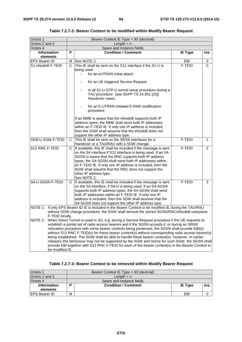
ETSI
ETSI TS 129 274 V12.6.0 (2014-10)843GPP TS 29.274 version 12.6.0 Release 12
Table 7.2.7-2: Bearer Context to be modified within Modify Bearer Request
Octets 1 Bearer Context IE Type = 93 (decimal) Octets 2 and 3 Length = n Octets 4 Spare and Instance fields
Information elements
P Condition / Comment IE Type Ins.
EPS Bearer ID M See NOTE 2. EBI 0 S1 eNodeB F-TEID C This IE shall be sent on the S11 interface if the S1-U is
being used: - for an eUTRAN initial attach
- for an UE triggered Service Request
- in all S1-U GTP-U tunnel setup procedure during a TAU procedure (see 3GPP TS 24.301 [23]) /handover cases.
- for an E-UTRAN Initiated E-RAB modification procedure.
If an MME is aware that the eNodeB supports both IP address types, the MME shall send both IP addresses within an F-TEID IE. If only one IP address is included, then the SGW shall assume that the eNodeB does not support the other IP address type.
F-TEID 0
S5/8-U SGW F-TEID C This IE shall be sent on the S5/S8 interfaces for a Handover or a TAU/RAU with a SGW change.
F-TEID 1
S12 RNC F-TEID C If available, this IE shall be included if the message is sent on the S4 interface if S12 interface is being used. If an S4-SGSN is aware that the RNC supports both IP address types, the S4-SGSN shall send both IP addresses within an F-TEID IE. If only one IP address is included, then the SGW shall assume that the RNC does not support the other IP address type. See NOTE 2.
F-TEID 2
S4-U SGSN F-TEID C If available, this IE shall be included if the message is sent on the S4 interface, if S4-U is being used. If an S4-SGSN supports both IP address types, the S4-SGSN shall send both IP addresses within an F-TEID IE. If only one IP address is included, then the SGW shall assume that the S4-SGSN does not support the other IP address type.
F-TEID 3
NOTE 1: If only EPS Bearer ID IE is included in the Bearer Context to be modified IE during the TAU/RAU without SGW change procedure, the SGW shall remove the stored SGSN/RNC/eNodeB userplane F-TEID locally.
NOTE 2: When Direct Tunnel is used in 3G, e.g. during a Service Request procedure if the UE requests to establish a partial set of radio access bearers and if the SGSN accepts it, or during an SRNS relocation procedure with some bearer contexts being preserved, the SGSN shall provide EBI(s) without S12 RNC F-TEID(s) for these bearer context(s) without corresponding radio access bearer(s) being established. The SGW shall be able to handle these bearer context(s). However, in earlier releases this behaviour may not be supported by the SGW and hence for such SGW, the SGSN shall provide EBI together with S12 RNC F-TEID for each of the bearer context(s) in the Bearer Context to be modified IE.
Table 7.2.7-3: Bearer Context to be removed within Modify Bearer Request
Octets 1 Bearer Context IE Type = 93 (decimal) Octets 2 and 3 Length = n Octets 4 Spare and Instance fields
Information elements
P Condition / Comment IE Type Ins.
EPS Bearer ID M EBI 0
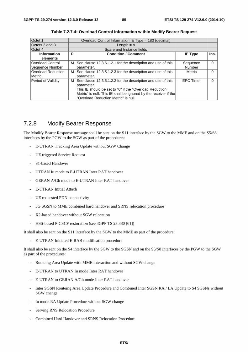
ETSI
ETSI TS 129 274 V12.6.0 (2014-10)853GPP TS 29.274 version 12.6.0 Release 12
Table 7.2.7-4: Overload Control Information within Modify Bearer Request
Octet 1 Overload Control Information IE Type = 180 (decimal) Octets 2 and 3 Length = n Octet 4 Spare and Instance fields
Information elements
P Condition / Comment IE Type Ins.
Overload Control Sequence Number
M See clause 12.3.5.1.2.1 for the description and use of this parameter.
Sequence Number
0
Overload Reduction Metric
M See clause 12.3.5.1.2.3 for the description and use of this parameter.
Metric 0
Period of Validity M See clause 12.3.5.1.2.2 for the description and use of this parameter. This IE should be set to "0" if the "Overload Reduction Metric" is null. This IE shall be ignored by the receiver if the "Overload Reduction Metric" is null.
EPC Timer 0
7.2.8 Modify Bearer Response
The Modify Bearer Response message shall be sent on the S11 interface by the SGW to the MME and on the S5/S8 interfaces by the PGW to the SGW as part of the procedures:
- E-UTRAN Tracking Area Update without SGW Change
- UE triggered Service Request
- S1-based Handover
- UTRAN Iu mode to E-UTRAN Inter RAT handover
- GERAN A/Gb mode to E-UTRAN Inter RAT handover
- E-UTRAN Initial Attach
- UE requested PDN connectivity
- 3G SGSN to MME combined hard handover and SRNS relocation procedure
- X2-based handover without SGW relocation
- HSS-based P-CSCF restoration (see 3GPP TS 23.380 [61])
It shall also be sent on the S11 interface by the SGW to the MME as part of the procedure:
- E-UTRAN Initiated E-RAB modification procedure
It shall also be sent on the S4 interface by the SGW to the SGSN and on the S5/S8 interfaces by the PGW to the SGW as part of the procedures:
- Routeing Area Update with MME interaction and without SGW change
- E-UTRAN to UTRAN Iu mode Inter RAT handover
- E-UTRAN to GERAN A/Gb mode Inter RAT handover
- Inter SGSN Routeing Area Update Procedure and Combined Inter SGSN RA / LA Update to S4 SGSNs without SGW change
- Iu mode RA Update Procedure without SGW change
- Serving RNS Relocation Procedure
- Combined Hard Handover and SRNS Relocation Procedure
ETSI
ETSI TS 129 274 V12.6.0 (2014-10)863GPP TS 29.274 version 12.6.0 Release 12
- Combined Cell / URA Update and SRNS Relocation Procedure
- Enhanced Serving RNS Relocation without SGW relocation
- UE Initiated Service Request Procedure
- Iu mode to A/Gb mode Intra SGSN Change
- A/Gb mode to Iu mode Intra SGSN Change
- Iu mode to A/Gb mode Inter-SGSN Change
- A/Gb mode to Iu mode Inter-SGSN Change
- Paging Response with no established user plane on S4
- PDP Context Activation Procedure
- HSS-based P-CSCF restoration (see 3GPP TS 23.380 [61])
It shall also be sent on the S4 interface by the SGSN to the SGW as part of:
- RAB Assignment Procedure
and on the S5/S8 interfaces by the PGW to the SGW as part of:
- Tracking Area Update procedure with SGW change
- Gn/Gp SGSN to S4 SGSN Routing Area Update
- X2 based handover with SGW relocation
- Gn/Gp SGSN to MME Tracking Area Update
- Enhanced Serving RNS Relocation with SGW relocation
- Routeing Area Update with MME interaction and with SGW change
- Inter SGSN Routeing Area Update Procedure and Combined Inter SGSN RA / LA Update using S4 with SGW change
- Iu mode RA Update Procedure using S4 with SGW change
- Restoration of PDN connections after an SGW failure if the MME/S4-SGSN and PGW support these procedures as specified in 3GPP TS 23.007 [17]
- MME triggered Serving GW relocation
- S4-SGSN triggered Serving GW relocation
If handling of default bearer fails, then Cause at the message level shall be a failure cause.
Possible Cause values are specified in Table 8.4-1. Message specific cause values are:
- "Request accepted".
- "Request accepted partially".
- "Context not found".
- "Service not supported".
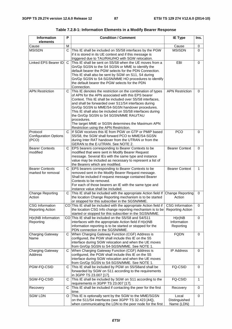
ETSI
ETSI TS 129 274 V12.6.0 (2014-10)873GPP TS 29.274 version 12.6.0 Release 12
Table 7.2.8-1: Information Elements in a Modify Bearer Response
Information elements
P Condition / Comment IE Type Ins.
Cause M Cause 0 MSISDN C This IE shall be included on S5/S8 interfaces by the PGW
if it is stored in its UE context and if this message is triggered due to TAU/RAU/HO with SGW relocation.
MSISDN 0
Linked EPS Bearer ID C This IE shall be sent on S5/S8 when the UE moves from a Gn/Gp SGSN to the S4 SGSN or MME to identify the default bearer the PGW selects for the PDN Connection. This IE shall also be sent by SGW on S11, S4 during Gn/Gp SGSN to S4-SGSN/MME HO procedures to identify the default bearer the PGW selects for the PDN Connection.
EBI 0
APN Restriction C This IE denotes the restriction on the combination of types of APN for the APN associated with this EPS bearer Context. This IE shall be included over S5/S8 interfaces, and shall be forwarded over S11/S4 interfaces during Gn/Gp SGSN to MME/S4-SGSN handover procedures. This IE shall also be included on S5/S8 interfaces during the Gn/Gp SGSN to S4 SGSN/MME RAU/TAU procedures. The target MME or SGSN determines the Maximum APN Restriction using the APN Restriction.
APN Restriction 0
Protocol Configuration Options (PCO)
C If SGW receives this IE from PGW on GTP or PMIP based S5/S8, the SGW shall forward PCO to MME/S4-SGSN during Inter RAT handover from the UTRAN or from the GERAN to the E-UTRAN. See NOTE 2.
PCO 0
Bearer Contexts modified
C EPS bearers corresponding to Bearer Contexts to be modified that were sent in Modify Bearer Request message. Several IEs with the same type and instance value may be included as necessary to represent a list of the Bearers which are modified.
Bearer Context 0
Bearer Contexts marked for removal
C EPS bearers corresponding to Bearer Contexts to be removed sent in the Modify Bearer Request message. Shall be included if request message contained Bearer Contexts to be removed. For each of those bearers an IE with the same type and instance value shall be included.
Bearer Context 1
Change Reporting Action
C This IE shall be included with the appropriate Action field If the location Change Reporting mechanism is to be started or stopped for this subscriber in the SGSN/MME.
Change Reporting Action
0
CSG Information Reporting Action
CO This IE shall be included with the appropriate Action field if the location CSG Info change reporting mechanism is to be started or stopped for this subscriber in the SGSN/MME.
CSG Information Reporting Action
0
H(e)NB Information Reporting
CO This IE shall be included on the S5/S8 and S4/S11 interfaces with the appropriate Action field if H(e)NB information reporting is to be started or stopped for the PDN connection in the SGSN/MME.
H(e)NB Information Reporting
0
Charging Gateway Name
C When Charging Gateway Function (CGF) Address is configured, the PGW shall include this IE on the S5 interface during SGW relocation and when the UE moves from Gn/Gp SGSN to S4-SGSN/MME. See NOTE 1.
FQDN 0
Charging Gateway Address
C When Charging Gateway Function (CGF) Address is configured, the PGW shall include this IE on the S5 interface during SGW relocation and when the UE moves from Gn/Gp SGSN to S4-SGSN/MME. See NOTE 1.
IP Address 0
PGW-FQ-CSID C This IE shall be included by PGW on S5/S8and shall be forwarded by SGW on S11 according to the requirements in 3GPP TS 23.007 [17].
FQ-CSID 0
SGW-FQ-CSID C This IE shall be included by SGW on S11 according to the requirements in 3GPP TS 23.007 [17].
FQ-CSID 1
Recovery C This IE shall be included if contacting the peer for the first time.
Recovery 0
SGW LDN O This IE is optionally sent by the SGW to the MME/SGSN on the S11/S4 interfaces (see 3GPP TS 32.423 [44]), when communicating the LDN to the peer node for the first
Local Distinguished Name (LDN)
0
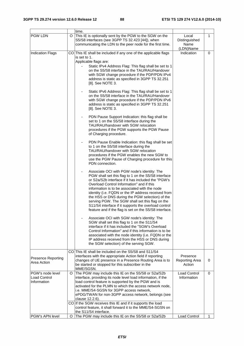
ETSI
ETSI TS 129 274 V12.6.0 (2014-10)883GPP TS 29.274 version 12.6.0 Release 12
time. PGW LDN O This IE is optionally sent by the PGW to the SGW on the
S5/S8 interfaces (see 3GPP TS 32.423 [44]), when communicating the LDN to the peer node for the first time.
Local Distinguished
Name (LDN)Name
1
Indication Flags CO This IE shall be included if any one of the applicable flags is set to 1. Applicable flags are:
- Static IPv4 Address Flag: This flag shall be set to 1 on the S5/S8 interface in the TAU/RAU/Handover with SGW change procedure if the PDP/PDN IPv4 address is static as specified in 3GPP TS 32.251 [8]. See NOTE 3.
- Static IPv6 Address Flag: This flag shall be set to 1 on the S5/S8 interface in the TAU/RAU/Handover with SGW change procedure if the PDP/PDN IPv6 address is static as specified in 3GPP TS 32.251 [8]. See NOTE 3.
- PDN Pause Support Indication: this flag shall be set to 1 on the S5/S8 interface during the TAU/RAU/handover with SGW relocation procedures if the PGW supports the PGW Pause of Charging procedure.
- PDN Pause Enable Indication: this flag shall be set to 1 on the S5/S8 interface during the TAU/RAU/handover with SGW relocation procedures if the PGW enables the new SGW to use the PGW Pause of Charging procedure for this PDN connection.
- Associate OCI with PGW node's identity: The PGW shall set this flag to 1 on the S5/S8 interface or S2a/S2b interface if it has included the "PGW's Overload Control Information" and if this information is to be associated with the node identity (i.e. FQDN or the IP address received from the HSS or DNS during the PGW selection) of the serving PGW. The SGW shall set this flag on the S11/S4 interface if it supports the overload control feature and if the flag is set on the S5/S8 interface.
- Associate OCI with SGW node's identity: The SGW shall set this flag to 1 on the S11/S4 interface if it has included the "SGW's Overload Control Information" and if this information is to be associated with the node identity (i.e. FQDN or the IP address received from the HSS or DNS during the SGW selection) of the serving SGW.
Indication 0
Presence Reporting Area Action
CO This IE shall be included on the S5/S8 and S11/S4 interfaces with the appropriate Action field if reporting changes of UE presence in a Presence Routing Area is to be started or stopped for this subscriber in the MME/SGSN.
Presence Reporting Area
Action 0
PGW's node level Load Control Information
O The PGW may include this IE on the S5/S8 or S2a/S2b interface, providing its node level load information, if the load control feature is supported by the PGW and is activated for the PLMN to which the access network node, i.e. MME/S4-SGSN for 3GPP access network, ePDG/TWAN for non-3GPP access network, belongs (see clause 12.2.6).
Load Control Information
0
CO If the SGW receives this IE and if it supports the load control feature, it shall forward it to the MME/S4-SGSN on the S11/S4 interface.
PGW's APN level O The PGW may include this IE on the S5/S8 or S2a/S2b Load Control 1
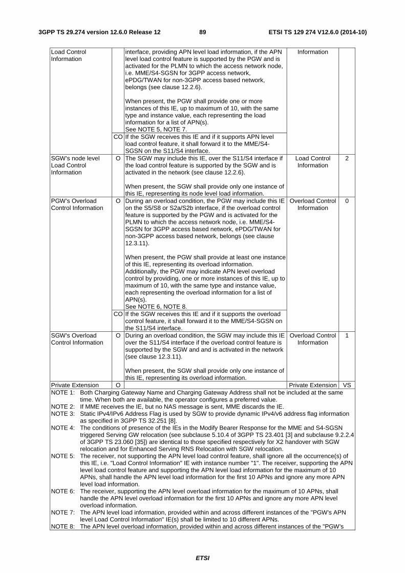
ETSI
ETSI TS 129 274 V12.6.0 (2014-10)893GPP TS 29.274 version 12.6.0 Release 12
Load Control Information
interface, providing APN level load information, if the APN level load control feature is supported by the PGW and is activated for the PLMN to which the access network node, i.e. MME/S4-SGSN for 3GPP access network, ePDG/TWAN for non-3GPP access based network, belongs (see clause 12.2.6). When present, the PGW shall provide one or more instances of this IE, up to maximum of 10, with the same type and instance value, each representing the load information for a list of APN(s). See NOTE 5, NOTE 7.
Information
CO If the SGW receives this IE and if it supports APN level load control feature, it shall forward it to the MME/S4-SGSN on the S11/S4 interface.
SGW's node level Load Control Information
O The SGW may include this IE, over the S11/S4 interface if the load control feature is supported by the SGW and is activated in the network (see clause 12.2.6). When present, the SGW shall provide only one instance of this IE, representing its node level load information.
Load Control Information
2
PGW's Overload Control Information
O During an overload condition, the PGW may include this IE on the S5/S8 or S2a/S2b interface, if the overload control feature is supported by the PGW and is activated for the PLMN to which the access network node, i.e. MME/S4-SGSN for 3GPP access based network, ePDG/TWAN for non-3GPP access based network, belongs (see clause 12.3.11). When present, the PGW shall provide at least one instance of this IE, representing its overload information. Additionally, the PGW may indicate APN level overload control by providing, one or more instances of this IE, up to maximum of 10, with the same type and instance value, each representing the overload information for a list of APN(s). See NOTE 6, NOTE 8.
Overload Control Information
0
CO If the SGW receives this IE and if it supports the overload control feature, it shall forward it to the MME/S4-SGSN on the S11/S4 interface.
SGW's Overload Control Information
O During an overload condition, the SGW may include this IE over the S11/S4 interface if the overload control feature is supported by the SGW and and is activated in the network (see clause 12.3.11). When present, the SGW shall provide only one instance of this IE, representing its overload information.
Overload Control Information
1
Private Extension O Private Extension VS NOTE 1: Both Charging Gateway Name and Charging Gateway Address shall not be included at the same
time. When both are available, the operator configures a preferred value. NOTE 2: If MME receives the IE, but no NAS message is sent, MME discards the IE. NOTE 3: Static IPv4/IPv6 Address Flag is used by SGW to provide dynamic IPv4/v6 address flag information
as specified in 3GPP TS 32.251 [8]. NOTE 4: The conditions of presence of the IEs in the Modify Bearer Response for the MME and S4-SGSN
triggered Serving GW relocation (see subclause 5.10.4 of 3GPP TS 23.401 [3] and subclause 9.2.2.4 of 3GPP TS 23.060 [35]) are identical to those specified respectively for X2 handover with SGW relocation and for Enhanced Serving RNS Relocation with SGW relocation.
NOTE 5: The receiver, not supporting the APN level load control feature, shall ignore all the occurrence(s) of this IE, i.e. "Load Control Information" IE with instance number "1". The receiver, supporting the APN level load control feature and supporting the APN level load information for the maximum of 10 APNs, shall handle the APN level load information for the first 10 APNs and ignore any more APN level load information.
NOTE 6: The receiver, supporting the APN level overload information for the maximum of 10 APNs, shall handle the APN level overload information for the first 10 APNs and ignore any more APN level overload information.
NOTE 7: The APN level load information, provided within and across different instances of the "PGW's APN level Load Control Information" IE(s) shall be limited to 10 different APNs.
NOTE 8: The APN level overload information, provided within and across different instances of the "PGW's
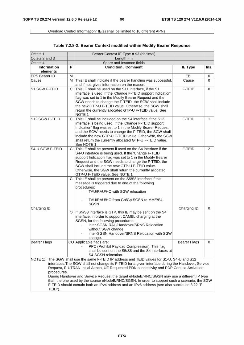
ETSI
ETSI TS 129 274 V12.6.0 (2014-10)903GPP TS 29.274 version 12.6.0 Release 12
Overload Control Information" IE(s) shall be limited to 10 different APNs.
Table 7.2.8-2: Bearer Context modified within Modify Bearer Response
Octets 1 Bearer Context IE Type = 93 (decimal) Octets 2 and 3 Length = n Octets 4 Spare and Instance fields
Information elements
P Condition / Comment IE Type Ins.
EPS Bearer ID M EBI 0 Cause M This IE shall indicate if the bearer handling was successful,
and if not, gives information on the reason. Cause 0
S1 SGW F-TEID C This IE shall be used on the S11 interface, if the S1 interface is used. If the 'Change F-TEID support Indication' flag was set to 1 in the Modify Bearer Request and the SGW needs to change the F-TEID, the SGW shall include the new GTP-U F-TEID value. Otherwise, the SGW shall return the currently allocated GTP-U F-TEID value. See NOTE 1
F-TEID 0
S12 SGW F-TEID C This IE shall be included on the S4 interface if the S12 interface is being used. If the 'Change F-TEID support Indication' flag was set to 1 in the Modify Bearer Request and the SGW needs to change the F-TEID, the SGW shall include the new GTP-U F-TEID value. Otherwise, the SGW shall return the currently allocated GTP-U F-TEID value. See NOTE 1
F-TEID 1
S4-U SGW F-TEID C This IE shall be present if used on the S4 interface if the S4-U interface is being used. If the 'Change F-TEID support Indication' flag was set to 1 in the Modify Bearer Request and the SGW needs to change the F-TEID, the SGW shall include the new GTP-U F-TEID value. Otherwise, the SGW shall return the currently allocated GTP-U F-TEID value. See NOTE 1
F-TEID 2
Charging ID
C This IE shall be present on the S5/S8 interface if this message is triggered due to one of the following procedures:
- TAU/RAU/HO with SGW relocation
- TAU/RAU/HO from Gn/Gp SGSN to MME/S4-SGSN
Charging ID 0 O If S5/S8 interface is GTP, this IE may be sent on the S4
interface, in order to support CAMEL charging at the SGSN, for the following procedures:
- inter-SGSN RAU/Handover/SRNS Relocation without SGW change.
- inter-SGSN Handover/SRNS Relocation with SGW change.
Bearer Flags CO Applicable flags are: - PPC (Prohibit Payload Compression): This flag
shall be sent on the S5/S8 and the S4 interfaces at S4-SGSN relocation.
Bearer Flags 0
NOTE 1: The SGW shall use the same F-TEID IP address and TEID values for S1-U, S4-U and S12 interfaces.The SGW shall not change its F-TEID for a given interface during the Handover, Service Request, E-UTRAN Initial Attach, UE Requested PDN connectivity and PDP Context Activation procedures. During Handover and Service Request the target eNodeB/RNC/SGSN may use a different IP type than the one used by the source eNodeB/RNC/SGSN. In order to support such a scenario, the SGW F-TEID should contain both an IPv4 address and an IPv6 address (see also subclause 8.22 "F-TEID").
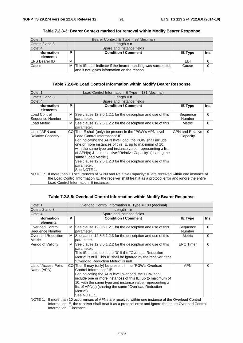
ETSI
ETSI TS 129 274 V12.6.0 (2014-10)913GPP TS 29.274 version 12.6.0 Release 12
Table 7.2.8-3: Bearer Context marked for removal within Modify Bearer Response
Octet 1 Bearer Context IE Type = 93 (decimal) Octets 2 and 3 Length = n Octet 4 Spare and Instance fields
Information elements
P Condition / Comment IE Type Ins.
EPS Bearer ID M EBI 0 Cause M This IE shall indicate if the bearer handling was successful,
and if not, gives information on the reason. Cause 0
Table 7.2.8-4: Load Control Information within Modify Bearer Response
Octet 1 Load Control Information IE Type = 181 (decimal) Octets 2 and 3 Length = n Octet 4 Spare and Instance fields
Information elements
P Condition / Comment IE Type Ins.
Load Control Sequence Number
M See clause 12.2.5.1.2.1 for the description and use of this parameter.
Sequence Number
0
Load Metric M See clause 12.2.5.1.2.2 for the description and use of this parameter.
Metric 0
List of APN and Relative Capacity
CO The IE shall (only) be present in the "PGW's APN level Load Control Information" IE. For indicating the APN level load, the PGW shall include one or more instances of this IE, up to maximum of 10, with the same type and instance value, representing a list of APN(s) & its respective "Relative Capacity" (sharing the same "Load Metric"). See clause 12.2.5.1.2.3 for the description and use of this parameter. See NOTE 1.
APN and Relative Capacity
0
NOTE 1: If more than 10 occurrences of "APN and Relative Capacity" IE are received within one instance of the Load Control Information IE, the receiver shall treat it as a protocol error and ignore the entire Load Control Information IE instance.
Table 7.2.8-5: Overload Control Information within Modify Bearer Response
Octet 1 Overload Control Information IE Type = 180 (decimal) Octets 2 and 3 Length = n Octet 4 Spare and Instance fields
Information elements
P Condition / Comment IE Type Ins.
Overload Control Sequence Number
M See clause 12.3.5.1.2.1 for the description and use of this parameter.
Sequence Number
0
Overload Reduction Metric
M See clause 12.3.5.1.2.3 for the description and use of this parameter.
Metric 0
Period of Validity M See clause 12.3.5.1.2.2 for the description and use of this parameter. This IE should be set to "0" if the "Overload Reduction Metric" is null. This IE shall be ignored by the receiver if the "Overload Reduction Metric" is null.
EPC Timer 0
List of Access Point Name (APN)
CO The IE may (only) be present in the "PGW's Overload Control Information" IE. For indicating the APN level overload, the PGW shall include one or more instances of this IE, up to maximum of 10, with the same type and instance value, representing a list of APN(s) (sharing the same "Overload Reduction Metric"). See NOTE 1.
APN 0
NOTE 1: If more than 10 occurrences of APNs are received within one instance of the Overload Control Information IE, the receiver shall treat it as a protocol error and ignore the entire Overload Control Information IE instance.
ETSI
ETSI TS 129 274 V12.6.0 (2014-10)923GPP TS 29.274 version 12.6.0 Release 12
7.2.9 Delete Session Request and Delete Bearer Request
7.2.9.1 Delete Session Request
The direction of this message shall be from MME/S4-SGSN to SGW, from SGW to PGW and from TWAN/ePDG to PGW (see Table 6.1-1).
A Delete Session Request message shall be sent on the S11 interface by the MME to the SGW and on the S5/S8 interface by the SGW to the PGW as part of the procedures:
- EUTRAN Initial Attach
- UE, HSS or MME Initiated Detach
- UE or MME Requested PDN Disconnection
It shall also be sent on the S4 interface by the SGSN to the SGW, and on the S5/S8 interface by the SGW to the PGW as part of
- MS, HLR or SGSN initiated detach procedure
- Combined GPRS/IMSI Attach
- MS and SGSN Initiated PDN connection Deactivation Procedure using S4
On the S11 interface by the MME to the SGW as part of the procedures:
- Tracking Area Update with SGW Change
- S1 Based Handover with SGW Change
- X2 Based Handover with SGW Relocation
- E-UTRAN to UTRAN Iu mode Inter RAT handover with SGW change
- E-UTRAN to GERAN A/Gb mode Inter RAT handover with SGW change
- Inter RAT handover cancel with SGW change
- MME to 3G Gn/Gp SGSN combined hard handover and SRNS relocation procedure
- MME to SGSN Routing Area Update
- E-UTRAN to Gn/Gp SGSN Inter RAT handover
- S1 Based handover cancel with SGW change
- Optimised Active Handover: E-UTRAN Access to CDMA2000 HRPD Access
- MME triggered Serving GW relocation
And on the S4 interface by the SGSN to the SGW as part of
- Enhanced Serving RNS Relocation with SGW relocation using S4
- Routing Area Update with SGW change
- SGSN to MME Tracking Area Update with SGW change
- SRNS Relocation Cancel Procedure Using S4
- Inter RAT with SGW change handover cancel
- Serving RNS relocation with SGW change
- UTRAN Iu mode to E-UTRAN Inter RAT handover with SGW change
ETSI
ETSI TS 129 274 V12.6.0 (2014-10)933GPP TS 29.274 version 12.6.0 Release 12
- GERAN A/Gb mode to E-UTRAN Inter RAT handover with SGW change
- S4 SGSN to Gn/Gp SGSN Routeing Area Update
- S4 SGSN to Gn/Gp SGSN Serving RNS Relocation Procedures
- S4 SGSN to Gn/Gp SGSN PS handover Procedures
- S4-SGSN triggered Serving GW relocation
The message shall also be sent on the S2b interface by the ePDG to the PGW as part of procedures:
- UE/ePDG Initiated Detach with GTP on S2b
- UE Requested PDN Disconnection with GTP on S2b
- HSS/AAA Initiated Detach with GTP on S2b
The message shall also be sent on the S2a interface by the TWAN to the PGW as part of procedures:
- UE/TWAN Initiated Detach and UE/TWAN Requested PDN Disconnection in WLAN on GTP S2a
- HSS/AAA Initiated Detach in WLAN on GTP S2a
This message may also be sent on S5/S8 interface by the SGW to the PGW:
- If Downlink Data Notification Acknowledge message with Context not found cause value is received.
During the detach procedure, if ISR is active and SGW receives a Delete Session Request, the SGW shall deactivate the ISR.
NOTE: The SGW can determine if it is a detach procedure based on e.g. it receives a Delete Session Request message for the last PDN Connection.
When ISR is active, during the Detach procedure the SGW shall forward the Delete Session Request message to the PGW on the S5/S8 interface after receiving both of the messages sent from the MME and the SGSN for the same PDN Connection.
If there are any procedure collisions, the Delete Session Request shall have precedence over any other Tunnel Management message.
During the handover procedure the Delete Session Request message shall not release the indirect data forwarding tunnels.
Possible Cause values are:
- "ISR deactivation ".
- "Network Failure".
- "QoS parameter mismatch".
Table 7.2.9.1-1 specifies the presence of the IEs in the message.
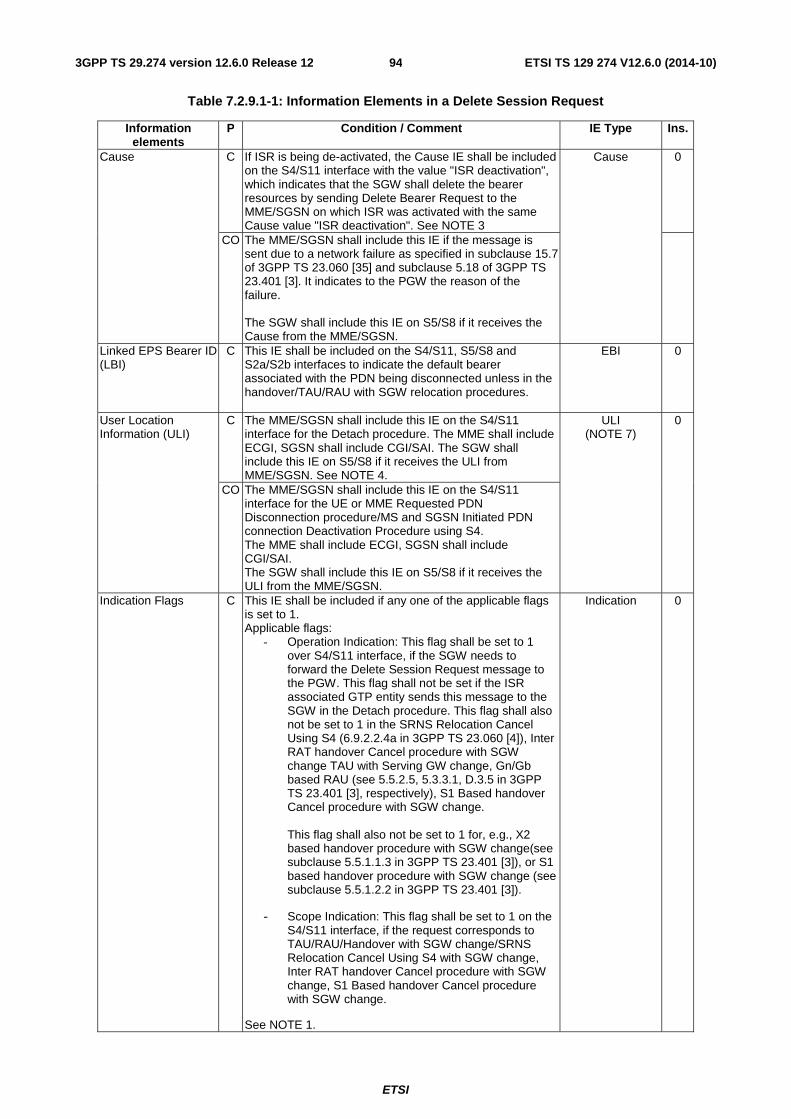
ETSI
ETSI TS 129 274 V12.6.0 (2014-10)943GPP TS 29.274 version 12.6.0 Release 12
Table 7.2.9.1-1: Information Elements in a Delete Session Request
Information elements
P Condition / Comment IE Type Ins.
Cause C If ISR is being de-activated, the Cause IE shall be included on the S4/S11 interface with the value "ISR deactivation", which indicates that the SGW shall delete the bearer resources by sending Delete Bearer Request to the MME/SGSN on which ISR was activated with the same Cause value "ISR deactivation". See NOTE 3
Cause 0
CO The MME/SGSN shall include this IE if the message is sent due to a network failure as specified in subclause 15.7 of 3GPP TS 23.060 [35] and subclause 5.18 of 3GPP TS 23.401 [3]. It indicates to the PGW the reason of the failure. The SGW shall include this IE on S5/S8 if it receives the Cause from the MME/SGSN.
Linked EPS Bearer ID (LBI)
C This IE shall be included on the S4/S11, S5/S8 and S2a/S2b interfaces to indicate the default bearer associated with the PDN being disconnected unless in the handover/TAU/RAU with SGW relocation procedures.
EBI 0
User Location Information (ULI)
C The MME/SGSN shall include this IE on the S4/S11 interface for the Detach procedure. The MME shall include ECGI, SGSN shall include CGI/SAI. The SGW shall include this IE on S5/S8 if it receives the ULI from MME/SGSN. See NOTE 4.
ULI (NOTE 7)
0
CO The MME/SGSN shall include this IE on the S4/S11 interface for the UE or MME Requested PDN Disconnection procedure/MS and SGSN Initiated PDN connection Deactivation Procedure using S4. The MME shall include ECGI, SGSN shall include CGI/SAI. The SGW shall include this IE on S5/S8 if it receives the ULI from the MME/SGSN.
Indication Flags C This IE shall be included if any one of the applicable flags is set to 1. Applicable flags:
- Operation Indication: This flag shall be set to 1 over S4/S11 interface, if the SGW needs to forward the Delete Session Request message to the PGW. This flag shall not be set if the ISR associated GTP entity sends this message to the SGW in the Detach procedure. This flag shall also not be set to 1 in the SRNS Relocation Cancel Using S4 (6.9.2.2.4a in 3GPP TS 23.060 [4]), Inter RAT handover Cancel procedure with SGW change TAU with Serving GW change, Gn/Gb based RAU (see 5.5.2.5, 5.3.3.1, D.3.5 in 3GPP TS 23.401 [3], respectively), S1 Based handover Cancel procedure with SGW change. This flag shall also not be set to 1 for, e.g., X2 based handover procedure with SGW change(see subclause 5.5.1.1.3 in 3GPP TS 23.401 [3]), or S1 based handover procedure with SGW change (see subclause 5.5.1.2.2 in 3GPP TS 23.401 [3]).
- Scope Indication: This flag shall be set to 1 on the S4/S11 interface, if the request corresponds to TAU/RAU/Handover with SGW change/SRNS Relocation Cancel Using S4 with SGW change, Inter RAT handover Cancel procedure with SGW change, S1 Based handover Cancel procedure with SGW change.
See NOTE 1.
Indication 0
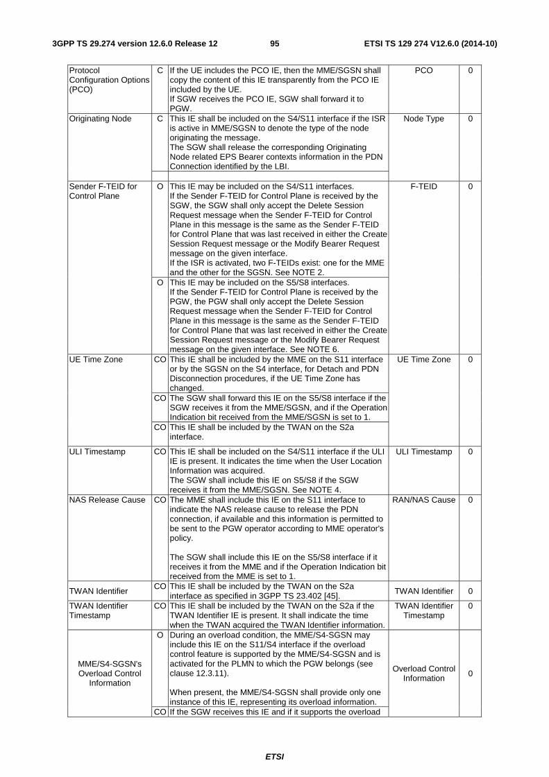
ETSI
ETSI TS 129 274 V12.6.0 (2014-10)953GPP TS 29.274 version 12.6.0 Release 12
Protocol Configuration Options (PCO)
C If the UE includes the PCO IE, then the MME/SGSN shall copy the content of this IE transparently from the PCO IE included by the UE. If SGW receives the PCO IE, SGW shall forward it to PGW.
PCO 0
Originating Node C This IE shall be included on the S4/S11 interface if the ISR is active in MME/SGSN to denote the type of the node originating the message. The SGW shall release the corresponding Originating Node related EPS Bearer contexts information in the PDN Connection identified by the LBI.
Node Type 0
Sender F-TEID for Control Plane
O This IE may be included on the S4/S11 interfaces. If the Sender F-TEID for Control Plane is received by the SGW, the SGW shall only accept the Delete Session Request message when the Sender F-TEID for Control Plane in this message is the same as the Sender F-TEID for Control Plane that was last received in either the Create Session Request message or the Modify Bearer Request message on the given interface. If the ISR is activated, two F-TEIDs exist: one for the MME and the other for the SGSN. See NOTE 2.
F-TEID 0
O This IE may be included on the S5/S8 interfaces. If the Sender F-TEID for Control Plane is received by the PGW, the PGW shall only accept the Delete Session Request message when the Sender F-TEID for Control Plane in this message is the same as the Sender F-TEID for Control Plane that was last received in either the Create Session Request message or the Modify Bearer Request message on the given interface. See NOTE 6.
UE Time Zone CO This IE shall be included by the MME on the S11 interface or by the SGSN on the S4 interface, for Detach and PDN Disconnection procedures, if the UE Time Zone has changed.
UE Time Zone 0
CO The SGW shall forward this IE on the S5/S8 interface if the SGW receives it from the MME/SGSN, and if the Operation Indication bit received from the MME/SGSN is set to 1.
CO This IE shall be included by the TWAN on the S2a interface.
ULI Timestamp CO This IE shall be included on the S4/S11 interface if the ULI IE is present. It indicates the time when the User Location Information was acquired. The SGW shall include this IE on S5/S8 if the SGW receives it from the MME/SGSN. See NOTE 4.
ULI Timestamp 0
NAS Release Cause CO The MME shall include this IE on the S11 interface to indicate the NAS release cause to release the PDN connection, if available and this information is permitted to be sent to the PGW operator according to MME operator's policy. The SGW shall include this IE on the S5/S8 interface if it receives it from the MME and if the Operation Indication bit received from the MME is set to 1.
RAN/NAS Cause 0
TWAN Identifier CO This IE shall be included by the TWAN on the S2a
interface as specified in 3GPP TS 23.402 [45]. TWAN Identifier 0
TWAN Identifier Timestamp
CO This IE shall be included by the TWAN on the S2a if the TWAN Identifier IE is present. It shall indicate the time when the TWAN acquired the TWAN Identifier information.
TWAN Identifier Timestamp
0
MME/S4-SGSN's Overload Control
Information
O During an overload condition, the MME/S4-SGSN may include this IE on the S11/S4 interface if the overload control feature is supported by the MME/S4-SGSN and is activated for the PLMN to which the PGW belongs (see clause 12.3.11). When present, the MME/S4-SGSN shall provide only one instance of this IE, representing its overload information.
Overload Control Information 0
CO If the SGW receives this IE and if it supports the overload
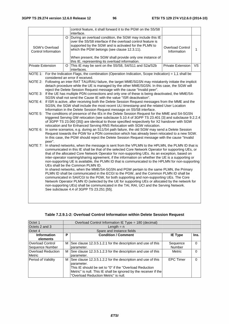
ETSI
ETSI TS 129 274 V12.6.0 (2014-10)963GPP TS 29.274 version 12.6.0 Release 12
control feature, it shall forward it to the PGW on the S5/S8 interface.
SGW's Overload Control Information
O During an overload condition, the SGW may include this IE over the S5/S8 interface if the overload control feature is supported by the SGW and is activated for the PLMN to which the PGW belongs (see clause 12.3.11). When present, the SGW shall provide only one instance of this IE, representing its overload information.
Overload Control Information 1
Private Extension O This IE may be sent on the S5/S8, S4/S11 and S2a/S2b interfaces.
Private Extension VS
NOTE 1: For the Indication Flags, the combination (Operation Indication, Scope Indication) = 1,1 shall be considered an error if received.
NOTE 2: Following an inter RAT TAU/RAU failure, the target MME/SGSN may mistakenly initiate the implicit detach procedure while the UE is managed by the other MME/SGSN. In this case, the SGW will reject the Delete Session Request message with the cause "Invalid peer".
NOTE 3: If the UE has multiple PDN connections and only one of these is being deactivated, the MME/S4-SGSN shall not send the Cause IE with the value "ISR deactivation".
NOTE 4: If ISR is active, after receiving both the Delete Session Request messages from the MME and the SGSN, the SGW shall include the most recent ULI timestamp and the related User Location Information in the Delete Session Request message on S5/S8 interface.
NOTE 5: The conditions of presence of the IEs in the Delete Session Request for the MME and S4-SGSN triggered Serving GW relocation (see subclause 5.10.4 of 3GPP TS 23.401 [3] and subclause 9.2.2.4 of 3GPP TS 23.060 [35]) are identical to those specified respectively for X2 handover with SGW relocation and for Enhanced Serving RNS Relocation with SGW relocation.
NOTE 6: In some scenarios, e.g. during an S11/S4 path failure, the old SGW may send a Delete Session Request towards the PGW for a PDN connection which has already been relocated to a new SGW. In this case, the PGW should reject the Delete Session Request message with the cause "Invalid peer".
NOTE 7: In shared networks, when the message is sent from the VPLMN to the HPLMN, the PLMN ID that is communicated in this IE shall be that of the selected Core Network Operator for supporting UEs, or that of the allocated Core Network Operator for non-supporting UEs. As an exception, based on inter-operator roaming/sharing agreement, if the information on whether the UE is a supporting or non-supporting UE is available, the PLMN ID that is communicated to the HPLMN for non-supporting UEs shall be the Common PLMN ID. In shared networks, when the MME/S4-SGSN and PGW pertain to the same PLMN, the Primary PLMN ID shall be communicated in the ECGI to the PGW, and the Common PLMN ID shall be communicated in SAI/CGI to the PGW, for both supporting and non-supporting UEs. The Core Network Operator PLMN ID (selected by the UE for supporting UEs or allocated by the network for non-supporting UEs) shall be communicated in the TAI, RAI, UCI and the Serving Network. See subclause 4.4 of 3GPP TS 23.251 [55].
Table 7.2.9.1-2: Overload Control Information within Delete Session Request
Octet 1 Overload Control Information IE Type = 180 (decimal) Octets 2 and 3 Length = n Octet 4 Spare and Instance fields
Information elements
P Condition / Comment IE Type Ins.
Overload Control Sequence Number
M See clause 12.3.5.1.2.1 for the description and use of this parameter.
Sequence Number
0
Overload Reduction Metric
M See clause 12.3.5.1.2.3 for the description and use of this parameter.
Metric 0
Period of Validity M See clause 12.3.5.1.2.2 for the description and use of this parameter. This IE should be set to "0" if the "Overload Reduction Metric" is null. This IE shall be ignored by the receiver if the "Overload Reduction Metric" is null.
EPC Timer 0

ETSI
ETSI TS 129 274 V12.6.0 (2014-10)973GPP TS 29.274 version 12.6.0 Release 12
7.2.9.2 Delete Bearer Request
The direction of this message shall be from PGW to SGW, from SGW to MME/S4-SGSN and from PGW to TWAN/ePDG (see Table 6.1-1).
A Delete Bearer Request message shall be sent on the S5/S8 and S4/S11 interfaces as part of the following procedures:
- PGW or MME initiated bearer deactivation procedures,
- UE requested Bearer Resource Modification,
- MS and SGSN Initiated Bearer Deactivation procedure using S4 or
- PGW initiated bearer deactivation procedure using S4.
In the above cases, this Request is sent by the PGW to the SGW and shall be forwarded to the MME or S4-SGSN.
The message shall also be sent on the S4/S11 interface by the SGW to the SGSN/MME to delete the bearer resources on the other ISR associated CN node if the ISRAI flag is not set in the Modify Bearer Request/Modify Access Bearers Request message.
The message shall also be sent on the S4/S11 interface by the SGW to the SGSN/MME to delete the bearer resources on the other ISR associated CN node in the TAU/RAU/Handover procedures if the ISR related Cause IE is included in the Delete Session Request message.
The message shall also be sent on the S2b interface by the PGW to the ePDG as part of PGW Initiated Bearer Resource Allocation Deactivation procedure with GTP on S2b.
The message shall also be sent on the S2a interface by the PGW to the TWAN as part of the PGW Initiated Bearer Resource Allocation Deactivation in WLAN on GTP on S2a procedure.
The message may also be sent on the S11/S4 interface by the SGW to the MME/S4 SGSN when the SGW receives the Error Indication from PGW for the default bearer or the ICMP message from a PGW that indicates the UE specific error indication as specified in 3GPP TS 23.007 [17].
Possible Cause values are:
- "RAT changed from 3GPP to Non-3GPP",
- "ISR deactivation",
- "Access changed from Non-3GPP to 3GPP",
- "Reactivation requested",
- "PDN reconnection to this APN disallowed",
- "PDN connection inactivity timer expires".
Table 7.2.9.2-1 specifies the presence of IEs in this message.
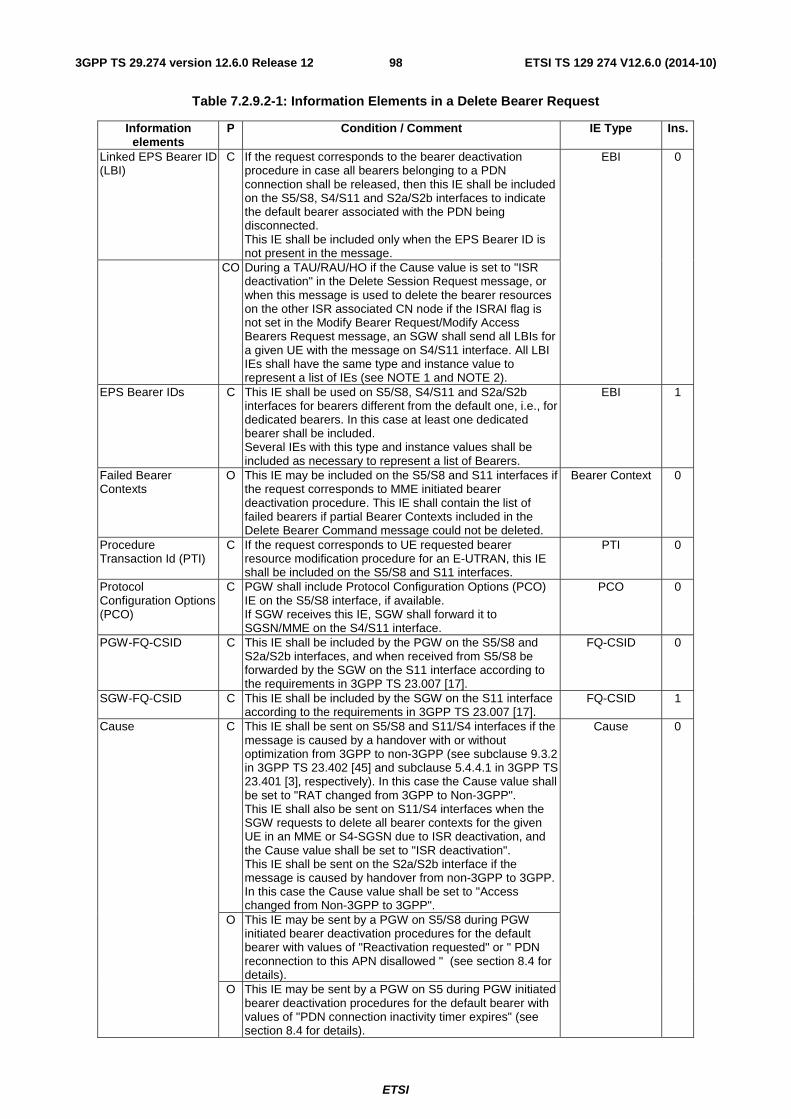
ETSI
ETSI TS 129 274 V12.6.0 (2014-10)983GPP TS 29.274 version 12.6.0 Release 12
Table 7.2.9.2-1: Information Elements in a Delete Bearer Request
Information elements
P Condition / Comment IE Type Ins.
Linked EPS Bearer ID (LBI)
C If the request corresponds to the bearer deactivation procedure in case all bearers belonging to a PDN connection shall be released, then this IE shall be included on the S5/S8, S4/S11 and S2a/S2b interfaces to indicate the default bearer associated with the PDN being disconnected. This IE shall be included only when the EPS Bearer ID is not present in the message.
EBI 0
CO During a TAU/RAU/HO if the Cause value is set to "ISR deactivation" in the Delete Session Request message, or when this message is used to delete the bearer resources on the other ISR associated CN node if the ISRAI flag is not set in the Modify Bearer Request/Modify Access Bearers Request message, an SGW shall send all LBIs for a given UE with the message on S4/S11 interface. All LBI IEs shall have the same type and instance value to represent a list of IEs (see NOTE 1 and NOTE 2).
EPS Bearer IDs C This IE shall be used on S5/S8, S4/S11 and S2a/S2b interfaces for bearers different from the default one, i.e., for dedicated bearers. In this case at least one dedicated bearer shall be included. Several IEs with this type and instance values shall be included as necessary to represent a list of Bearers.
EBI 1
Failed Bearer Contexts
O This IE may be included on the S5/S8 and S11 interfaces if the request corresponds to MME initiated bearer deactivation procedure. This IE shall contain the list of failed bearers if partial Bearer Contexts included in the Delete Bearer Command message could not be deleted.
Bearer Context 0
Procedure Transaction Id (PTI)
C If the request corresponds to UE requested bearer resource modification procedure for an E-UTRAN, this IE shall be included on the S5/S8 and S11 interfaces.
PTI 0
Protocol Configuration Options (PCO)
C PGW shall include Protocol Configuration Options (PCO) IE on the S5/S8 interface, if available. If SGW receives this IE, SGW shall forward it to SGSN/MME on the S4/S11 interface.
PCO 0
PGW-FQ-CSID C This IE shall be included by the PGW on the S5/S8 and S2a/S2b interfaces, and when received from S5/S8 be forwarded by the SGW on the S11 interface according to the requirements in 3GPP TS 23.007 [17].
FQ-CSID 0
SGW-FQ-CSID C This IE shall be included by the SGW on the S11 interface according to the requirements in 3GPP TS 23.007 [17].
FQ-CSID 1
Cause C This IE shall be sent on S5/S8 and S11/S4 interfaces if the message is caused by a handover with or without optimization from 3GPP to non-3GPP (see subclause 9.3.2 in 3GPP TS 23.402 [45] and subclause 5.4.4.1 in 3GPP TS 23.401 [3], respectively). In this case the Cause value shall be set to "RAT changed from 3GPP to Non-3GPP". This IE shall also be sent on S11/S4 interfaces when the SGW requests to delete all bearer contexts for the given UE in an MME or S4-SGSN due to ISR deactivation, and the Cause value shall be set to "ISR deactivation". This IE shall be sent on the S2a/S2b interface if the message is caused by handover from non-3GPP to 3GPP. In this case the Cause value shall be set to "Access changed from Non-3GPP to 3GPP".
Cause 0
O This IE may be sent by a PGW on S5/S8 during PGW initiated bearer deactivation procedures for the default bearer with values of "Reactivation requested" or " PDN reconnection to this APN disallowed " (see section 8.4 for details).
O This IE may be sent by a PGW on S5 during PGW initiated bearer deactivation procedures for the default bearer with values of "PDN connection inactivity timer expires" (see section 8.4 for details).
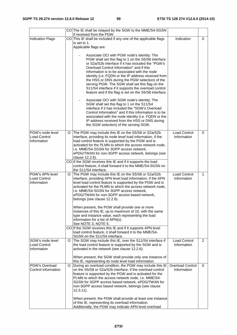
ETSI
ETSI TS 129 274 V12.6.0 (2014-10)993GPP TS 29.274 version 12.6.0 Release 12
CO The IE shall be relayed by the SGW to the MME/S4-SGSN if received from the PGW.
Indication Flags CO This IE shall be included if any one of the applicable flags is set to 1. Applicable flags are:
- Associate OCI with PGW node's identity: The PGW shall set this flag to 1 on the S5/S8 interface or S2a/S2b interface if it has included the "PGW's Overload Control Information" and if this information is to be associated with the node identity (i.e. FQDN or the IP address received from the HSS or DNS during the PGW selection) of the serving PGW. The SGW shall set this flag on the S11/S4 interface if it supports the overload control feature and if the flag is set on the S5/S8 interface.
- Associate OCI with SGW node's identity: The SGW shall set this flag to 1 on the S11/S4 interface if it has included the "SGW's Overload Control Information" and if this information is to be associated with the node identity (i.e. FQDN or the IP address received from the HSS or DNS during the SGW selection) of the serving SGW.
Indication 0
PGW's node level Load Control Information
O The PGW may include this IE on the S5/S8 or S2a/S2b interface, providing its node level load information, if the load control feature is supported by the PGW and is activated for the PLMN to which the access network node, i.e. MME/S4-SGSN for 3GPP access network, ePDG/TWAN for non-3GPP access network, belongs (see clause 12.2.6).
Load Control Information
0
CO If the SGW receives this IE and if it supports the load control feature, it shall forward it to the MME/S4-SGSN on the S11/S4 interface.
PGW's APN level Load Control Information
O The PGW may include this IE on the S5/S8 or S2a/S2b interface, providing APN level load information, if the APN level load control feature is supported by the PGW and is activated for the PLMN to which the access network node, i.e. MME/S4-SGSN for 3GPP access network, ePDG/TWAN for non-3GPP access based network, belongs (see clause 12.2.6). When present, the PGW shall provide one or more instances of this IE, up to maximum of 10, with the same type and instance value, each representing the load information for a list of APN(s). See NOTE 3, NOTE 5.
Load Control Information
1
CO If the SGW receives this IE and if it supports APN level load control feature, it shall forward it to the MME/S4-SGSN on the S11/S4 interface.
SGW's node level Load Control Information
O The SGW may include this IE, over the S11/S4 interface if the load control feature is supported by the SGW and is activated in the network (see clause 12.2.6). When present, the SGW shall provide only one instance of this IE, representing its node level load information.
Load Control Information
2
PGW's Overload Control Information
O During an overload condition, the PGW may include this IE on the S5/S8 or S2a/S2b interface, if the overload control feature is supported by the PGW and is activated for the PLMN to which the access network node, i.e. MME/S4-SGSN for 3GPP access based network, ePDG/TWAN for non-3GPP access based network, belongs (see clause 12.3.11). When present, the PGW shall provide at least one instance of this IE, representing its overload information. Additionally, the PGW may indicate APN level overload
Overload Control Information
0
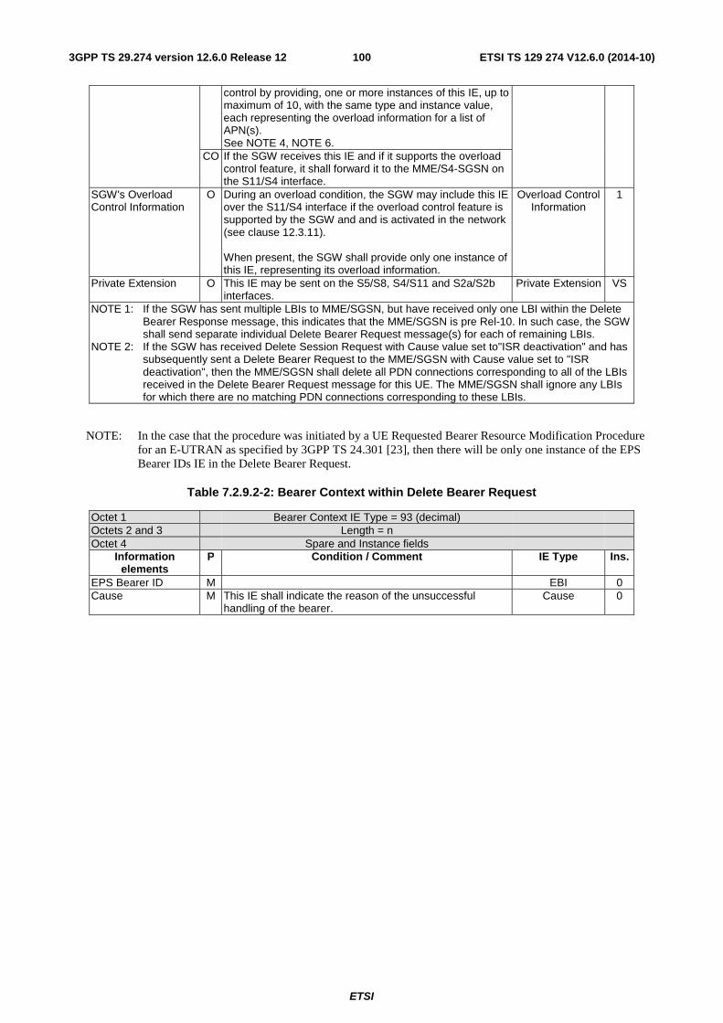
ETSI
ETSI TS 129 274 V12.6.0 (2014-10)1003GPP TS 29.274 version 12.6.0 Release 12
control by providing, one or more instances of this IE, up to maximum of 10, with the same type and instance value, each representing the overload information for a list of APN(s). See NOTE 4, NOTE 6.
CO If the SGW receives this IE and if it supports the overload control feature, it shall forward it to the MME/S4-SGSN on the S11/S4 interface.
SGW's Overload Control Information
O During an overload condition, the SGW may include this IE over the S11/S4 interface if the overload control feature is supported by the SGW and and is activated in the network (see clause 12.3.11). When present, the SGW shall provide only one instance of this IE, representing its overload information.
Overload Control Information
1
Private Extension O This IE may be sent on the S5/S8, S4/S11 and S2a/S2b interfaces.
Private Extension VS
NOTE 1: If the SGW has sent multiple LBIs to MME/SGSN, but have received only one LBI within the Delete Bearer Response message, this indicates that the MME/SGSN is pre Rel-10. In such case, the SGW shall send separate individual Delete Bearer Request message(s) for each of remaining LBIs.
NOTE 2: If the SGW has received Delete Session Request with Cause value set to"ISR deactivation" and has subsequently sent a Delete Bearer Request to the MME/SGSN with Cause value set to "ISR deactivation", then the MME/SGSN shall delete all PDN connections corresponding to all of the LBIs received in the Delete Bearer Request message for this UE. The MME/SGSN shall ignore any LBIs for which there are no matching PDN connections corresponding to these LBIs.
NOTE: In the case that the procedure was initiated by a UE Requested Bearer Resource Modification Procedure for an E-UTRAN as specified by 3GPP TS 24.301 [23], then there will be only one instance of the EPS Bearer IDs IE in the Delete Bearer Request.
Table 7.2.9.2-2: Bearer Context within Delete Bearer Request
Octet 1 Bearer Context IE Type = 93 (decimal) Octets 2 and 3 Length = n Octet 4 Spare and Instance fields
Information elements
P Condition / Comment IE Type Ins.
EPS Bearer ID M EBI 0 Cause M This IE shall indicate the reason of the unsuccessful
handling of the bearer. Cause 0
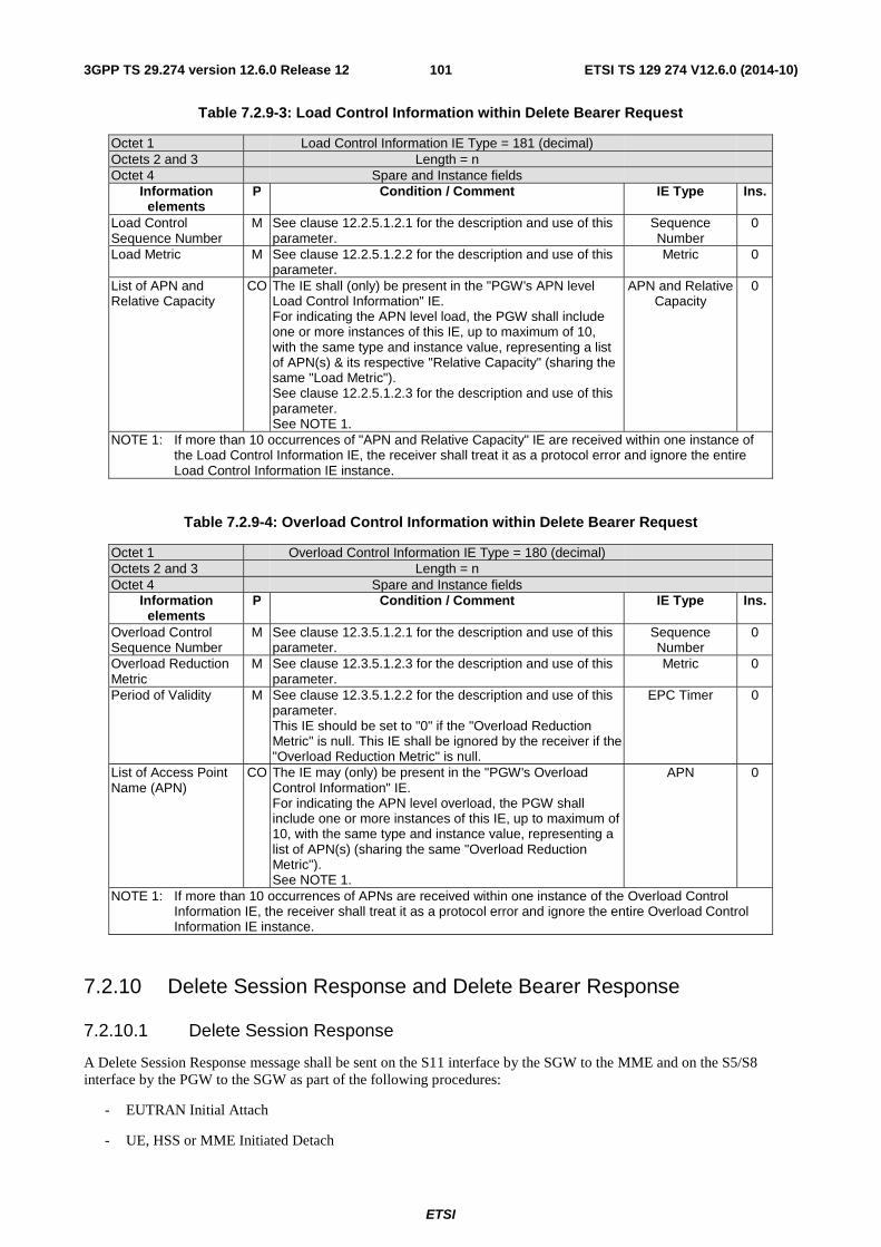
ETSI
ETSI TS 129 274 V12.6.0 (2014-10)1013GPP TS 29.274 version 12.6.0 Release 12
Table 7.2.9-3: Load Control Information within Delete Bearer Request
Octet 1 Load Control Information IE Type = 181 (decimal) Octets 2 and 3 Length = n Octet 4 Spare and Instance fields
Information elements
P Condition / Comment IE Type Ins.
Load Control Sequence Number
M See clause 12.2.5.1.2.1 for the description and use of this parameter.
Sequence Number
0
Load Metric M See clause 12.2.5.1.2.2 for the description and use of this parameter.
Metric 0
List of APN and Relative Capacity
CO The IE shall (only) be present in the "PGW's APN level Load Control Information" IE. For indicating the APN level load, the PGW shall include one or more instances of this IE, up to maximum of 10, with the same type and instance value, representing a list of APN(s) & its respective "Relative Capacity" (sharing the same "Load Metric"). See clause 12.2.5.1.2.3 for the description and use of this parameter. See NOTE 1.
APN and Relative Capacity
0
NOTE 1: If more than 10 occurrences of "APN and Relative Capacity" IE are received within one instance of the Load Control Information IE, the receiver shall treat it as a protocol error and ignore the entire Load Control Information IE instance.
Table 7.2.9-4: Overload Control Information within Delete Bearer Request
Octet 1 Overload Control Information IE Type = 180 (decimal) Octets 2 and 3 Length = n Octet 4 Spare and Instance fields
Information elements
P Condition / Comment IE Type Ins.
Overload Control Sequence Number
M See clause 12.3.5.1.2.1 for the description and use of this parameter.
Sequence Number
0
Overload Reduction Metric
M See clause 12.3.5.1.2.3 for the description and use of this parameter.
Metric 0
Period of Validity M See clause 12.3.5.1.2.2 for the description and use of this parameter. This IE should be set to "0" if the "Overload Reduction Metric" is null. This IE shall be ignored by the receiver if the "Overload Reduction Metric" is null.
EPC Timer 0
List of Access Point Name (APN)
CO The IE may (only) be present in the "PGW's Overload Control Information" IE. For indicating the APN level overload, the PGW shall include one or more instances of this IE, up to maximum of 10, with the same type and instance value, representing a list of APN(s) (sharing the same "Overload Reduction Metric"). See NOTE 1.
APN 0
NOTE 1: If more than 10 occurrences of APNs are received within one instance of the Overload Control Information IE, the receiver shall treat it as a protocol error and ignore the entire Overload Control Information IE instance.
7.2.10 Delete Session Response and Delete Bearer Response
7.2.10.1 Delete Session Response
A Delete Session Response message shall be sent on the S11 interface by the SGW to the MME and on the S5/S8 interface by the PGW to the SGW as part of the following procedures:
- EUTRAN Initial Attach
- UE, HSS or MME Initiated Detach
ETSI
ETSI TS 129 274 V12.6.0 (2014-10)1023GPP TS 29.274 version 12.6.0 Release 12
- UE or MME Requested PDN Disconnection
It shall also be sent on the S4 interface by the SGW to the SGSN and on the S5/S8 interface by the PGW to the SGW as part of the procedures:
- MS, HLR or SGSN initiated detach procedure
- Combined GPRS/IMSI Attach
- MS and SGSN Initiated Default Bearer Deactivation Procedure using S4
On the S11 interface by the SGW to the MME as part of the procedures:
- Tracking Area Update with SGW Change
- S1 Based Handover with SGW Change
- X2 Based Handover with SGW Relocation
- E-UTRAN to UTRAN Iu mode Inter RAT handover with SGW change
- E-UTRAN to GERAN A/Gb mode Inter RAT handover with SGW change
- Inter RAT handover cancel with SGW change
- MME to 3G Gn/Gp SGSN combined hard handover and SRNS relocation procedure
- MME to SGSN Routing Area Update
- E-UTRAN to Gn/Gp SGSN Inter RAT handover
- S1 Based handover cancel with SGW change
- Optimised Active Handover: E-UTRAN Access to CDMA2000 HRPD Access
- MME triggered Serving GW relocation
And on the S4 interface by the SGW to the SGSN as part of the procedures:
- Enhanced Serving RNS Relocation with SGW relocation using S4
- Routing Area Update with SGW change
- SGSN to MME Tracking Area Update with SGW change
- Serving RNS relocation with SGW change
- UTRAN Iu mode to E-UTRAN Inter RAT handover with SGW change
- GERAN A/Gb mode to E-UTRAN Inter RAT handover with SGW change
- S4 SGSN to Gn/Gp SGSN Routeing Area Update
- S4 SGSN to Gn/Gp SGSN Serving RNS Relocation Procedures
- S4 SGSN to Gn/Gp SGSN PS handover Procedures
- S4-SGSN triggered Serving GW relocation
The message shall also be sent on the S2b interface by the PGW to the ePDG as part of procedures:
- UE/ePDG Initiated Detach with GTP on S2b
- UE Requested PDN Disconnection with GTP on S2b
- HSS/AAA Initiated Detach with GTP on S2b
The message shall also be sent on the S2a interface by the PGW to the TWAN as part of procedures:
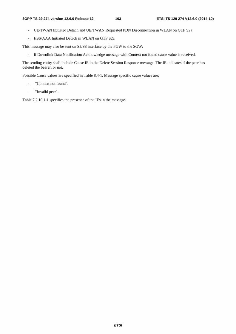
ETSI
ETSI TS 129 274 V12.6.0 (2014-10)1033GPP TS 29.274 version 12.6.0 Release 12
- UE/TWAN Initiated Detach and UE/TWAN Requested PDN Disconnection in WLAN on GTP S2a
- HSS/AAA Initiated Detach in WLAN on GTP S2a
This message may also be sent on S5/S8 interface by the PGW to the SGW:
- If Downlink Data Notification Acknowledge message with Context not found cause value is received.
The sending entity shall include Cause IE in the Delete Session Response message. The IE indicates if the peer has deleted the bearer, or not.
Possible Cause values are specified in Table 8.4-1. Message specific cause values are:
- "Context not found".
- "Invalid peer".
Table 7.2.10.1-1 specifies the presence of the IEs in the message.
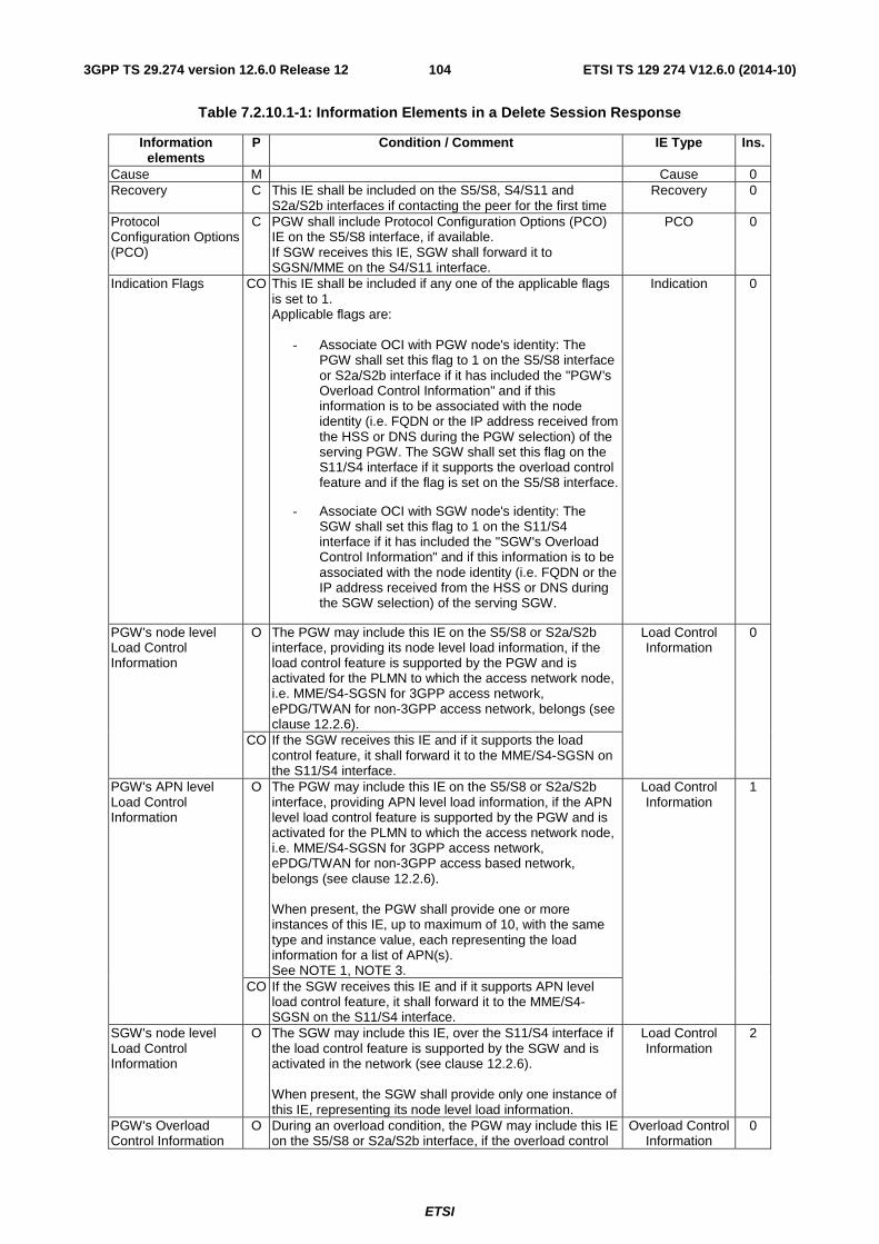
ETSI
ETSI TS 129 274 V12.6.0 (2014-10)1043GPP TS 29.274 version 12.6.0 Release 12
Table 7.2.10.1-1: Information Elements in a Delete Session Response
Information elements
P Condition / Comment IE Type Ins.
Cause M Cause 0 Recovery C This IE shall be included on the S5/S8, S4/S11 and
S2a/S2b interfaces if contacting the peer for the first time Recovery 0
Protocol Configuration Options (PCO)
C PGW shall include Protocol Configuration Options (PCO) IE on the S5/S8 interface, if available. If SGW receives this IE, SGW shall forward it to SGSN/MME on the S4/S11 interface.
PCO 0
Indication Flags CO This IE shall be included if any one of the applicable flags is set to 1. Applicable flags are:
- Associate OCI with PGW node's identity: The PGW shall set this flag to 1 on the S5/S8 interface or S2a/S2b interface if it has included the "PGW's Overload Control Information" and if this information is to be associated with the node identity (i.e. FQDN or the IP address received from the HSS or DNS during the PGW selection) of the serving PGW. The SGW shall set this flag on the S11/S4 interface if it supports the overload control feature and if the flag is set on the S5/S8 interface.
- Associate OCI with SGW node's identity: The SGW shall set this flag to 1 on the S11/S4 interface if it has included the "SGW's Overload Control Information" and if this information is to be associated with the node identity (i.e. FQDN or the IP address received from the HSS or DNS during the SGW selection) of the serving SGW.
Indication 0
PGW's node level Load Control Information
O The PGW may include this IE on the S5/S8 or S2a/S2b interface, providing its node level load information, if the load control feature is supported by the PGW and is activated for the PLMN to which the access network node, i.e. MME/S4-SGSN for 3GPP access network, ePDG/TWAN for non-3GPP access network, belongs (see clause 12.2.6).
Load Control Information
0
CO If the SGW receives this IE and if it supports the load control feature, it shall forward it to the MME/S4-SGSN on the S11/S4 interface.
PGW's APN level Load Control Information
O The PGW may include this IE on the S5/S8 or S2a/S2b interface, providing APN level load information, if the APN level load control feature is supported by the PGW and is activated for the PLMN to which the access network node, i.e. MME/S4-SGSN for 3GPP access network, ePDG/TWAN for non-3GPP access based network, belongs (see clause 12.2.6). When present, the PGW shall provide one or more instances of this IE, up to maximum of 10, with the same type and instance value, each representing the load information for a list of APN(s). See NOTE 1, NOTE 3.
Load Control Information
1
CO If the SGW receives this IE and if it supports APN level load control feature, it shall forward it to the MME/S4-SGSN on the S11/S4 interface.
SGW's node level Load Control Information
O The SGW may include this IE, over the S11/S4 interface if the load control feature is supported by the SGW and is activated in the network (see clause 12.2.6). When present, the SGW shall provide only one instance of this IE, representing its node level load information.
Load Control Information
2
PGW's Overload Control Information
O During an overload condition, the PGW may include this IE on the S5/S8 or S2a/S2b interface, if the overload control
Overload Control Information
0
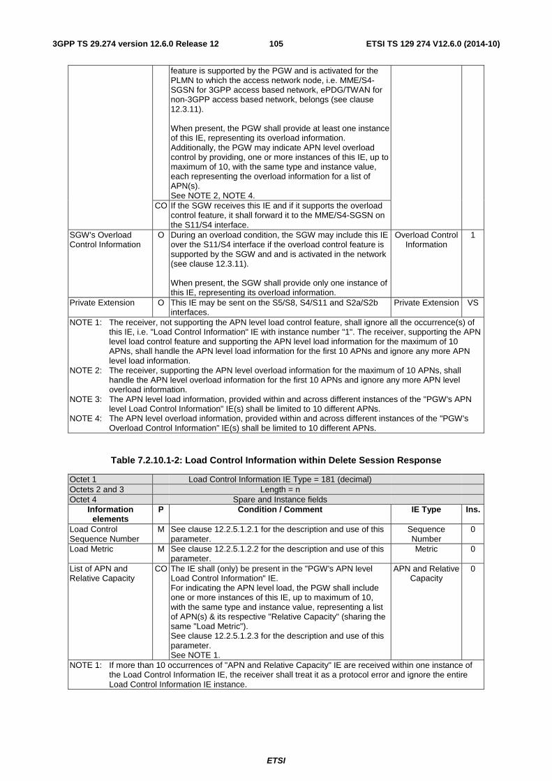
ETSI
ETSI TS 129 274 V12.6.0 (2014-10)1053GPP TS 29.274 version 12.6.0 Release 12
feature is supported by the PGW and is activated for the PLMN to which the access network node, i.e. MME/S4-SGSN for 3GPP access based network, ePDG/TWAN for non-3GPP access based network, belongs (see clause 12.3.11). When present, the PGW shall provide at least one instance of this IE, representing its overload information. Additionally, the PGW may indicate APN level overload control by providing, one or more instances of this IE, up to maximum of 10, with the same type and instance value, each representing the overload information for a list of APN(s). See NOTE 2, NOTE 4.
CO If the SGW receives this IE and if it supports the overload control feature, it shall forward it to the MME/S4-SGSN on the S11/S4 interface.
SGW's Overload Control Information
O During an overload condition, the SGW may include this IE over the S11/S4 interface if the overload control feature is supported by the SGW and and is activated in the network (see clause 12.3.11). When present, the SGW shall provide only one instance of this IE, representing its overload information.
Overload Control Information
1
Private Extension O This IE may be sent on the S5/S8, S4/S11 and S2a/S2b interfaces.
Private Extension VS
NOTE 1: The receiver, not supporting the APN level load control feature, shall ignore all the occurrence(s) of this IE, i.e. "Load Control Information" IE with instance number "1". The receiver, supporting the APN level load control feature and supporting the APN level load information for the maximum of 10 APNs, shall handle the APN level load information for the first 10 APNs and ignore any more APN level load information.
NOTE 2: The receiver, supporting the APN level overload information for the maximum of 10 APNs, shall handle the APN level overload information for the first 10 APNs and ignore any more APN level overload information.
NOTE 3: The APN level load information, provided within and across different instances of the "PGW's APN level Load Control Information" IE(s) shall be limited to 10 different APNs.
NOTE 4: The APN level overload information, provided within and across different instances of the "PGW's Overload Control Information" IE(s) shall be limited to 10 different APNs.
Table 7.2.10.1-2: Load Control Information within Delete Session Response
Octet 1 Load Control Information IE Type = 181 (decimal) Octets 2 and 3 Length = n Octet 4 Spare and Instance fields
Information elements
P Condition / Comment IE Type Ins.
Load Control Sequence Number
M See clause 12.2.5.1.2.1 for the description and use of this parameter.
Sequence Number
0
Load Metric M See clause 12.2.5.1.2.2 for the description and use of this parameter.
Metric 0
List of APN and Relative Capacity
CO The IE shall (only) be present in the "PGW's APN level Load Control Information" IE. For indicating the APN level load, the PGW shall include one or more instances of this IE, up to maximum of 10, with the same type and instance value, representing a list of APN(s) & its respective "Relative Capacity" (sharing the same "Load Metric"). See clause 12.2.5.1.2.3 for the description and use of this parameter. See NOTE 1.
APN and Relative Capacity
0
NOTE 1: If more than 10 occurrences of "APN and Relative Capacity" IE are received within one instance of the Load Control Information IE, the receiver shall treat it as a protocol error and ignore the entire Load Control Information IE instance.
ETSI
ETSI TS 129 274 V12.6.0 (2014-10)1063GPP TS 29.274 version 12.6.0 Release 12
Table 7.2.10.1-3: Overload Control Information within Delete Session Response
Octet 1 Overload Control Information IE Type = 180 (decimal) Octets 2 and 3 Length = n Octet 4 Spare and Instance fields
Information elements
P Condition / Comment IE Type Ins.
Overload Control Sequence Number
M See clause 12.3.5.1.2.1 for the description and use of this parameter.
Sequence Number
0
Overload Reduction Metric
M See clause 12.3.5.1.2.3 for the description and use of this parameter.
Metric 0
Period of Validity M See clause 12.3.5.1.2.2 for the description and use of this parameter. This IE should be set to "0" if the "Overload Reduction Metric" is null. This IE shall be ignored by the receiver if the "Overload Reduction Metric" is null.
EPC Timer 0
List of Access Point Name (APN)
CO The IE may (only) be present in the "PGW's Overload Control Information" IE. For indicating the APN level overload, the PGW shall include one or more instances of this IE, up to maximum of 10, with the same type and instance value, representing a list of APN(s) (sharing the same "Overload Reduction Metric"). See NOTE 1.
APN 0
NOTE 1: If more than 10 occurrences of APNs are received within one instance of the Overload Control Information IE, the receiver shall treat it as a protocol error and ignore the entire Overload Control Information IE instance.
7.2.10.2 Delete Bearer Response
The Delete Bearer Response shall be sent as a response of Delete Bearer Request.
Possible Cause values are specified in Table 8.4-1. Message specific cause values are:
- "Request accepted".
- "Request accepted partially".
- "Context not found".
- "Temporarily rejected due to handover/TAU/RAU procedure in progress".
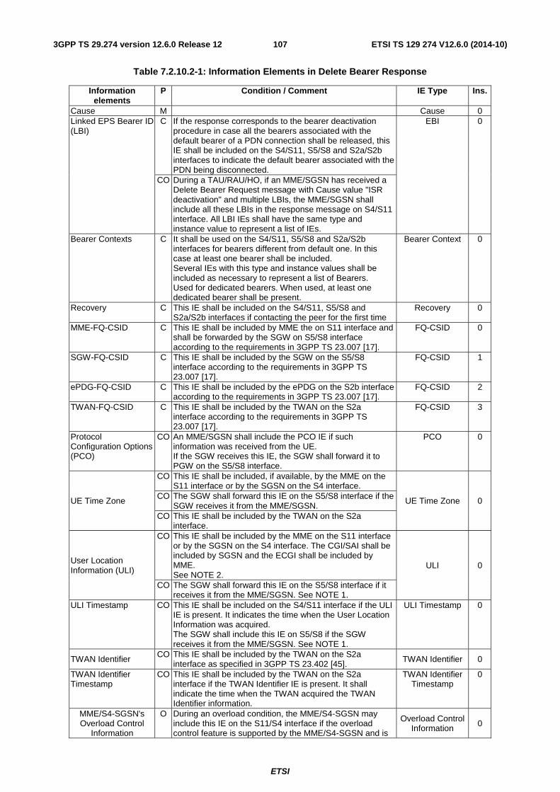
ETSI
ETSI TS 129 274 V12.6.0 (2014-10)1073GPP TS 29.274 version 12.6.0 Release 12
Table 7.2.10.2-1: Information Elements in Delete Bearer Response
Information elements
P Condition / Comment IE Type Ins.
Cause M Cause 0 Linked EPS Bearer ID (LBI)
C If the response corresponds to the bearer deactivation procedure in case all the bearers associated with the default bearer of a PDN connection shall be released, this IE shall be included on the S4/S11, S5/S8 and S2a/S2b interfaces to indicate the default bearer associated with the PDN being disconnected.
EBI 0
CO During a TAU/RAU/HO, if an MME/SGSN has received a Delete Bearer Request message with Cause value "ISR deactivation" and multiple LBIs, the MME/SGSN shall include all these LBIs in the response message on S4/S11 interface. All LBI IEs shall have the same type and instance value to represent a list of IEs.
Bearer Contexts C It shall be used on the S4/S11, S5/S8 and S2a/S2b interfaces for bearers different from default one. In this case at least one bearer shall be included. Several IEs with this type and instance values shall be included as necessary to represent a list of Bearers. Used for dedicated bearers. When used, at least one dedicated bearer shall be present.
Bearer Context 0
Recovery C This IE shall be included on the S4/S11, S5/S8 and S2a/S2b interfaces if contacting the peer for the first time
Recovery 0
MME-FQ-CSID C This IE shall be included by MME the on S11 interface and shall be forwarded by the SGW on S5/S8 interface according to the requirements in 3GPP TS 23.007 [17].
FQ-CSID 0
SGW-FQ-CSID C This IE shall be included by the SGW on the S5/S8 interface according to the requirements in 3GPP TS 23.007 [17].
FQ-CSID 1
ePDG-FQ-CSID C This IE shall be included by the ePDG on the S2b interface according to the requirements in 3GPP TS 23.007 [17].
FQ-CSID 2
TWAN-FQ-CSID C This IE shall be included by the TWAN on the S2a interface according to the requirements in 3GPP TS 23.007 [17].
FQ-CSID 3
Protocol Configuration Options (PCO)
CO An MME/SGSN shall include the PCO IE if such information was received from the UE. If the SGW receives this IE, the SGW shall forward it to PGW on the S5/S8 interface.
PCO 0
UE Time Zone
CO This IE shall be included, if available, by the MME on the S11 interface or by the SGSN on the S4 interface.
UE Time Zone 0 CO The SGW shall forward this IE on the S5/S8 interface if the SGW receives it from the MME/SGSN.
CO This IE shall be included by the TWAN on the S2a interface.
User Location Information (ULI)
CO This IE shall be included by the MME on the S11 interface or by the SGSN on the S4 interface. The CGI/SAI shall be included by SGSN and the ECGI shall be included by MME. See NOTE 2.
ULI 0
CO The SGW shall forward this IE on the S5/S8 interface if it receives it from the MME/SGSN. See NOTE 1.
ULI Timestamp CO This IE shall be included on the S4/S11 interface if the ULI IE is present. It indicates the time when the User Location Information was acquired. The SGW shall include this IE on S5/S8 if the SGW receives it from the MME/SGSN. See NOTE 1.
ULI Timestamp 0
TWAN Identifier CO This IE shall be included by the TWAN on the S2a interface as specified in 3GPP TS 23.402 [45]. TWAN Identifier 0
TWAN Identifier Timestamp
CO This IE shall be included by the TWAN on the S2a interface if the TWAN Identifier IE is present. It shall indicate the time when the TWAN acquired the TWAN Identifier information.
TWAN Identifier Timestamp
0
MME/S4-SGSN's Overload Control
Information
O During an overload condition, the MME/S4-SGSN may include this IE on the S11/S4 interface if the overload control feature is supported by the MME/S4-SGSN and is
Overload Control Information 0
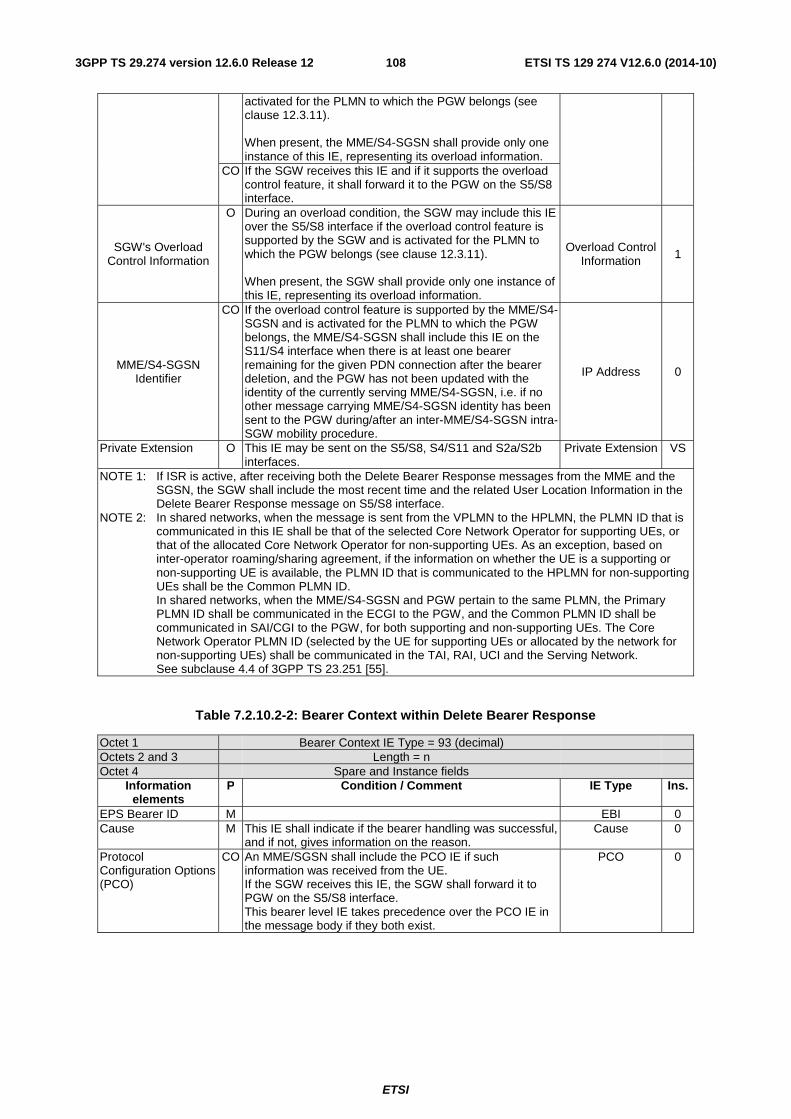
ETSI
ETSI TS 129 274 V12.6.0 (2014-10)1083GPP TS 29.274 version 12.6.0 Release 12
activated for the PLMN to which the PGW belongs (see clause 12.3.11). When present, the MME/S4-SGSN shall provide only one instance of this IE, representing its overload information.
CO If the SGW receives this IE and if it supports the overload control feature, it shall forward it to the PGW on the S5/S8 interface.
SGW's Overload Control Information
O During an overload condition, the SGW may include this IE over the S5/S8 interface if the overload control feature is supported by the SGW and is activated for the PLMN to which the PGW belongs (see clause 12.3.11). When present, the SGW shall provide only one instance of this IE, representing its overload information.
Overload Control Information 1
MME/S4-SGSN Identifier
CO If the overload control feature is supported by the MME/S4-SGSN and is activated for the PLMN to which the PGW belongs, the MME/S4-SGSN shall include this IE on the S11/S4 interface when there is at least one bearer remaining for the given PDN connection after the bearer deletion, and the PGW has not been updated with the identity of the currently serving MME/S4-SGSN, i.e. if no other message carrying MME/S4-SGSN identity has been sent to the PGW during/after an inter-MME/S4-SGSN intra-SGW mobility procedure.
IP Address 0
Private Extension O This IE may be sent on the S5/S8, S4/S11 and S2a/S2b interfaces.
Private Extension VS
NOTE 1: If ISR is active, after receiving both the Delete Bearer Response messages from the MME and the SGSN, the SGW shall include the most recent time and the related User Location Information in the Delete Bearer Response message on S5/S8 interface.
NOTE 2: In shared networks, when the message is sent from the VPLMN to the HPLMN, the PLMN ID that is communicated in this IE shall be that of the selected Core Network Operator for supporting UEs, or that of the allocated Core Network Operator for non-supporting UEs. As an exception, based on inter-operator roaming/sharing agreement, if the information on whether the UE is a supporting or non-supporting UE is available, the PLMN ID that is communicated to the HPLMN for non-supporting UEs shall be the Common PLMN ID. In shared networks, when the MME/S4-SGSN and PGW pertain to the same PLMN, the Primary PLMN ID shall be communicated in the ECGI to the PGW, and the Common PLMN ID shall be communicated in SAI/CGI to the PGW, for both supporting and non-supporting UEs. The Core Network Operator PLMN ID (selected by the UE for supporting UEs or allocated by the network for non-supporting UEs) shall be communicated in the TAI, RAI, UCI and the Serving Network. See subclause 4.4 of 3GPP TS 23.251 [55].
Table 7.2.10.2-2: Bearer Context within Delete Bearer Response
Octet 1 Bearer Context IE Type = 93 (decimal) Octets 2 and 3 Length = n Octet 4 Spare and Instance fields
Information elements
P Condition / Comment IE Type Ins.
EPS Bearer ID M EBI 0 Cause M This IE shall indicate if the bearer handling was successful,
and if not, gives information on the reason. Cause 0
Protocol Configuration Options (PCO)
CO An MME/SGSN shall include the PCO IE if such information was received from the UE. If the SGW receives this IE, the SGW shall forward it to PGW on the S5/S8 interface. This bearer level IE takes precedence over the PCO IE in the message body if they both exist.
PCO 0
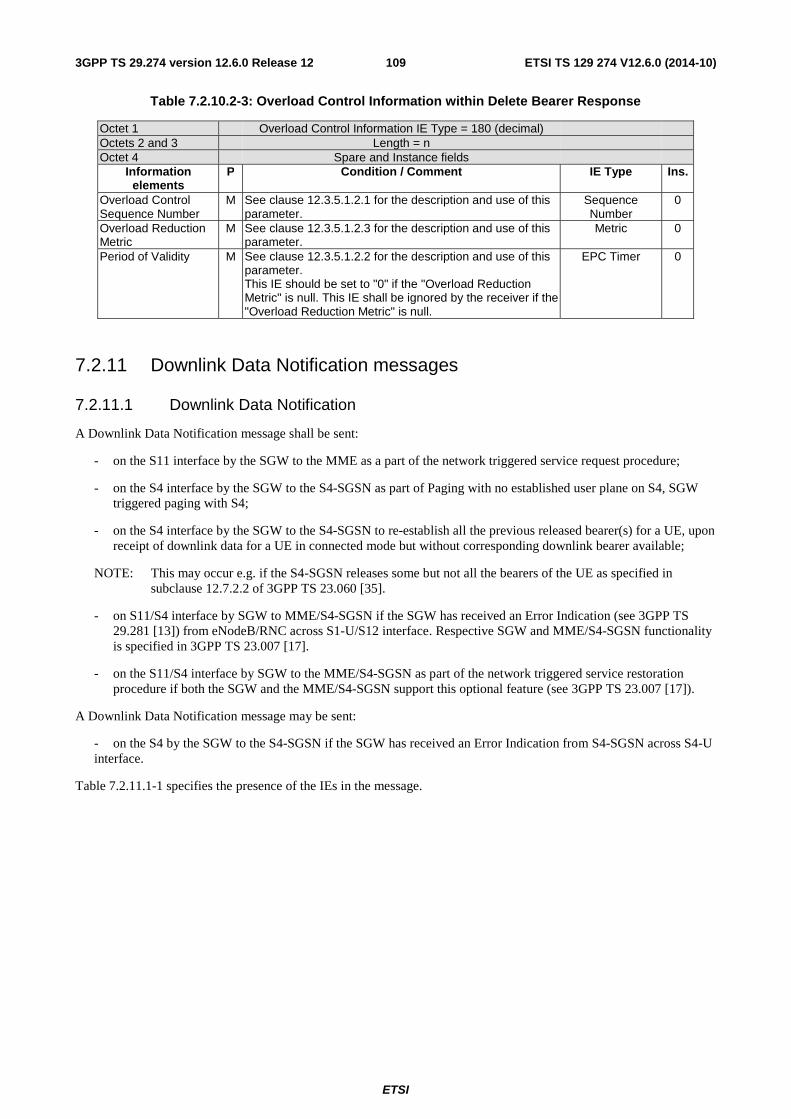
ETSI
ETSI TS 129 274 V12.6.0 (2014-10)1093GPP TS 29.274 version 12.6.0 Release 12
Table 7.2.10.2-3: Overload Control Information within Delete Bearer Response
Octet 1 Overload Control Information IE Type = 180 (decimal) Octets 2 and 3 Length = n Octet 4 Spare and Instance fields
Information elements
P Condition / Comment IE Type Ins.
Overload Control Sequence Number
M See clause 12.3.5.1.2.1 for the description and use of this parameter.
Sequence Number
0
Overload Reduction Metric
M See clause 12.3.5.1.2.3 for the description and use of this parameter.
Metric 0
Period of Validity M See clause 12.3.5.1.2.2 for the description and use of this parameter. This IE should be set to "0" if the "Overload Reduction Metric" is null. This IE shall be ignored by the receiver if the "Overload Reduction Metric" is null.
EPC Timer 0
7.2.11 Downlink Data Notification messages
7.2.11.1 Downlink Data Notification
A Downlink Data Notification message shall be sent:
- on the S11 interface by the SGW to the MME as a part of the network triggered service request procedure;
- on the S4 interface by the SGW to the S4-SGSN as part of Paging with no established user plane on S4, SGW triggered paging with S4;
- on the S4 interface by the SGW to the S4-SGSN to re-establish all the previous released bearer(s) for a UE, upon receipt of downlink data for a UE in connected mode but without corresponding downlink bearer available;
NOTE: This may occur e.g. if the S4-SGSN releases some but not all the bearers of the UE as specified in subclause 12.7.2.2 of 3GPP TS 23.060 [35].
- on S11/S4 interface by SGW to MME/S4-SGSN if the SGW has received an Error Indication (see 3GPP TS 29.281 [13]) from eNodeB/RNC across S1-U/S12 interface. Respective SGW and MME/S4-SGSN functionality is specified in 3GPP TS 23.007 [17].
- on the S11/S4 interface by SGW to the MME/S4-SGSN as part of the network triggered service restoration procedure if both the SGW and the MME/S4-SGSN support this optional feature (see 3GPP TS 23.007 [17]).
A Downlink Data Notification message may be sent:
- on the S4 by the SGW to the S4-SGSN if the SGW has received an Error Indication from S4-SGSN across S4-U interface.
Table 7.2.11.1-1 specifies the presence of the IEs in the message.
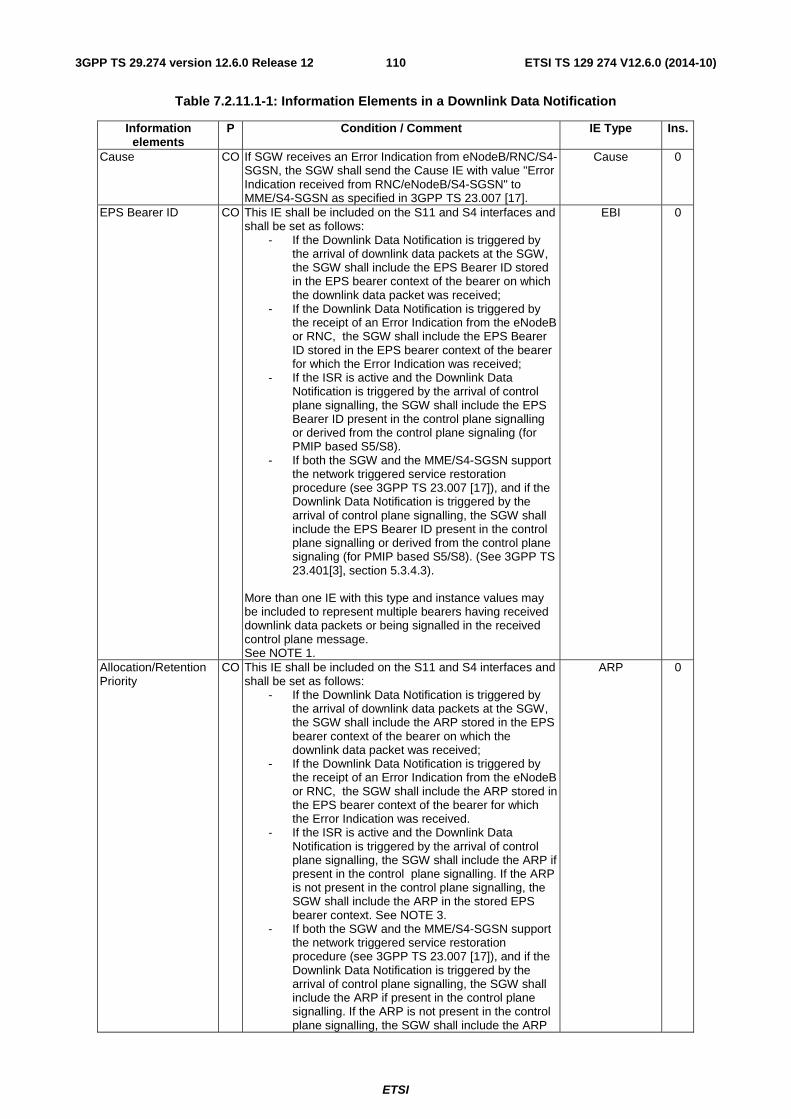
ETSI
ETSI TS 129 274 V12.6.0 (2014-10)1103GPP TS 29.274 version 12.6.0 Release 12
Table 7.2.11.1-1: Information Elements in a Downlink Data Notification
Information elements
P Condition / Comment IE Type Ins.
Cause CO If SGW receives an Error Indication from eNodeB/RNC/S4-SGSN, the SGW shall send the Cause IE with value "Error Indication received from RNC/eNodeB/S4-SGSN" to MME/S4-SGSN as specified in 3GPP TS 23.007 [17].
Cause 0
EPS Bearer ID CO This IE shall be included on the S11 and S4 interfaces and shall be set as follows:
- If the Downlink Data Notification is triggered by the arrival of downlink data packets at the SGW, the SGW shall include the EPS Bearer ID stored in the EPS bearer context of the bearer on which the downlink data packet was received;
- If the Downlink Data Notification is triggered by the receipt of an Error Indication from the eNodeB or RNC, the SGW shall include the EPS Bearer ID stored in the EPS bearer context of the bearer for which the Error Indication was received;
- If the ISR is active and the Downlink Data Notification is triggered by the arrival of control plane signalling, the SGW shall include the EPS Bearer ID present in the control plane signalling or derived from the control plane signaling (for PMIP based S5/S8).
- If both the SGW and the MME/S4-SGSN support the network triggered service restoration procedure (see 3GPP TS 23.007 [17]), and if the Downlink Data Notification is triggered by the arrival of control plane signalling, the SGW shall include the EPS Bearer ID present in the control plane signalling or derived from the control plane signaling (for PMIP based S5/S8). (See 3GPP TS 23.401[3], section 5.3.4.3).
More than one IE with this type and instance values may be included to represent multiple bearers having received downlink data packets or being signalled in the received control plane message. See NOTE 1.
EBI 0
Allocation/Retention Priority
CO This IE shall be included on the S11 and S4 interfaces and shall be set as follows:
- If the Downlink Data Notification is triggered by the arrival of downlink data packets at the SGW, the SGW shall include the ARP stored in the EPS bearer context of the bearer on which the downlink data packet was received;
- If the Downlink Data Notification is triggered by the receipt of an Error Indication from the eNodeB or RNC, the SGW shall include the ARP stored in the EPS bearer context of the bearer for which the Error Indication was received.
- If the ISR is active and the Downlink Data Notification is triggered by the arrival of control plane signalling, the SGW shall include the ARP if present in the control plane signalling. If the ARP is not present in the control plane signalling, the SGW shall include the ARP in the stored EPS bearer context. See NOTE 3.
- If both the SGW and the MME/S4-SGSN support the network triggered service restoration procedure (see 3GPP TS 23.007 [17]), and if the Downlink Data Notification is triggered by the arrival of control plane signalling, the SGW shall include the ARP if present in the control plane signalling. If the ARP is not present in the control plane signalling, the SGW shall include the ARP
ARP 0
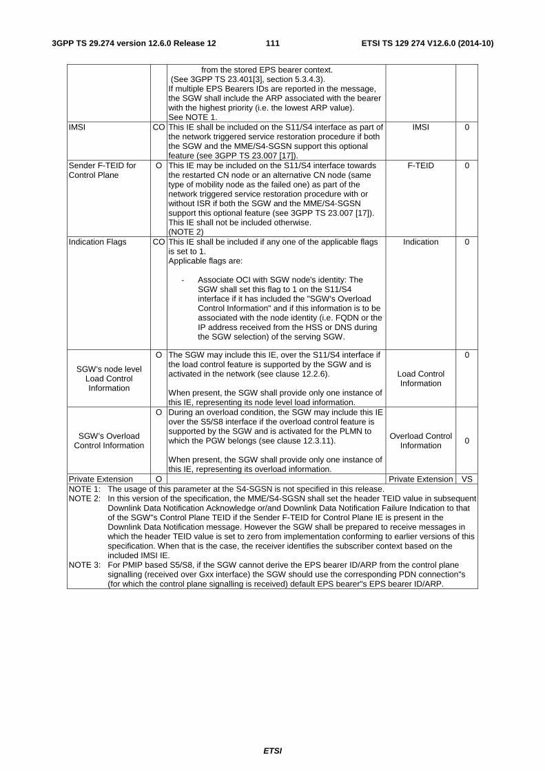
ETSI
ETSI TS 129 274 V12.6.0 (2014-10)1113GPP TS 29.274 version 12.6.0 Release 12
from the stored EPS bearer context. (See 3GPP TS 23.401[3], section 5.3.4.3). If multiple EPS Bearers IDs are reported in the message, the SGW shall include the ARP associated with the bearer with the highest priority (i.e. the lowest ARP value). See NOTE 1.
IMSI CO This IE shall be included on the S11/S4 interface as part of the network triggered service restoration procedure if both the SGW and the MME/S4-SGSN support this optional feature (see 3GPP TS 23.007 [17]).
IMSI 0
Sender F-TEID for Control Plane
O This IE may be included on the S11/S4 interface towards the restarted CN node or an alternative CN node (same type of mobility node as the failed one) as part of the network triggered service restoration procedure with or without ISR if both the SGW and the MME/S4-SGSN support this optional feature (see 3GPP TS 23.007 [17]). This IE shall not be included otherwise. (NOTE 2)
F-TEID 0
Indication Flags CO This IE shall be included if any one of the applicable flags is set to 1. Applicable flags are:
- Associate OCI with SGW node's identity: The SGW shall set this flag to 1 on the S11/S4 interface if it has included the "SGW's Overload Control Information" and if this information is to be associated with the node identity (i.e. FQDN or the IP address received from the HSS or DNS during the SGW selection) of the serving SGW.
Indication 0
SGW's node level Load Control Information
O The SGW may include this IE, over the S11/S4 interface if the load control feature is supported by the SGW and is activated in the network (see clause 12.2.6). When present, the SGW shall provide only one instance of this IE, representing its node level load information.
Load Control Information
0
SGW's Overload Control Information
O During an overload condition, the SGW may include this IE over the S5/S8 interface if the overload control feature is supported by the SGW and is activated for the PLMN to which the PGW belongs (see clause 12.3.11). When present, the SGW shall provide only one instance of this IE, representing its overload information.
Overload Control Information 0
Private Extension O Private Extension VS NOTE 1: The usage of this parameter at the S4-SGSN is not specified in this release. NOTE 2: In this version of the specification, the MME/S4-SGSN shall set the header TEID value in subsequent
Downlink Data Notification Acknowledge or/and Downlink Data Notification Failure Indication to that of the SGW"s Control Plane TEID if the Sender F-TEID for Control Plane IE is present in the Downlink Data Notification message. However the SGW shall be prepared to receive messages in which the header TEID value is set to zero from implementation conforming to earlier versions of this specification. When that is the case, the receiver identifies the subscriber context based on the included IMSI IE.
NOTE 3: For PMIP based S5/S8, if the SGW cannot derive the EPS bearer ID/ARP from the control plane signalling (received over Gxx interface) the SGW should use the corresponding PDN connection"s (for which the control plane signalling is received) default EPS bearer"s EPS bearer ID/ARP.
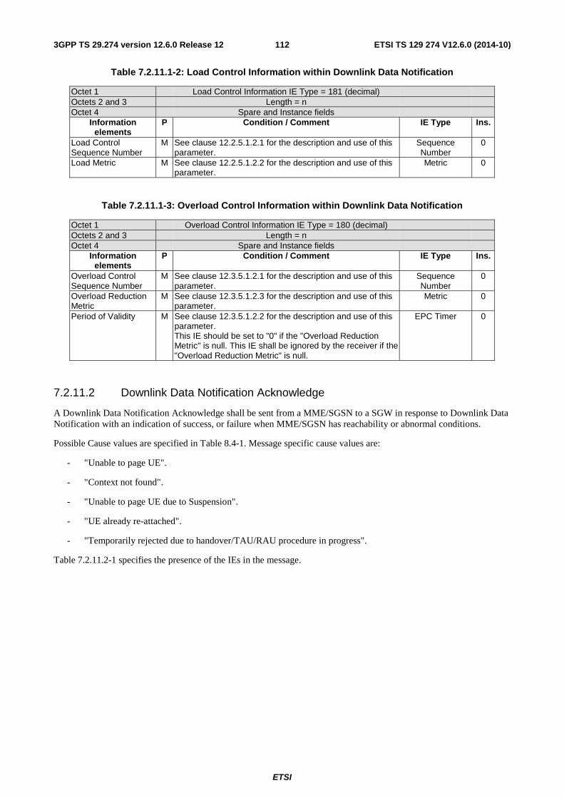
ETSI
ETSI TS 129 274 V12.6.0 (2014-10)1123GPP TS 29.274 version 12.6.0 Release 12
Table 7.2.11.1-2: Load Control Information within Downlink Data Notification
Octet 1 Load Control Information IE Type = 181 (decimal) Octets 2 and 3 Length = n Octet 4 Spare and Instance fields
Information elements
P Condition / Comment IE Type Ins.
Load Control Sequence Number
M See clause 12.2.5.1.2.1 for the description and use of this parameter.
Sequence Number
0
Load Metric M See clause 12.2.5.1.2.2 for the description and use of this parameter.
Metric 0
Table 7.2.11.1-3: Overload Control Information within Downlink Data Notification
Octet 1 Overload Control Information IE Type = 180 (decimal) Octets 2 and 3 Length = n Octet 4 Spare and Instance fields
Information elements
P Condition / Comment IE Type Ins.
Overload Control Sequence Number
M See clause 12.3.5.1.2.1 for the description and use of this parameter.
Sequence Number
0
Overload Reduction Metric
M See clause 12.3.5.1.2.3 for the description and use of this parameter.
Metric 0
Period of Validity M See clause 12.3.5.1.2.2 for the description and use of this parameter. This IE should be set to "0" if the "Overload Reduction Metric" is null. This IE shall be ignored by the receiver if the "Overload Reduction Metric" is null.
EPC Timer 0
7.2.11.2 Downlink Data Notification Acknowledge
A Downlink Data Notification Acknowledge shall be sent from a MME/SGSN to a SGW in response to Downlink Data Notification with an indication of success, or failure when MME/SGSN has reachability or abnormal conditions.
Possible Cause values are specified in Table 8.4-1. Message specific cause values are:
- "Unable to page UE".
- "Context not found".
- "Unable to page UE due to Suspension".
- "UE already re-attached".
- "Temporarily rejected due to handover/TAU/RAU procedure in progress".
Table 7.2.11.2-1 specifies the presence of the IEs in the message.
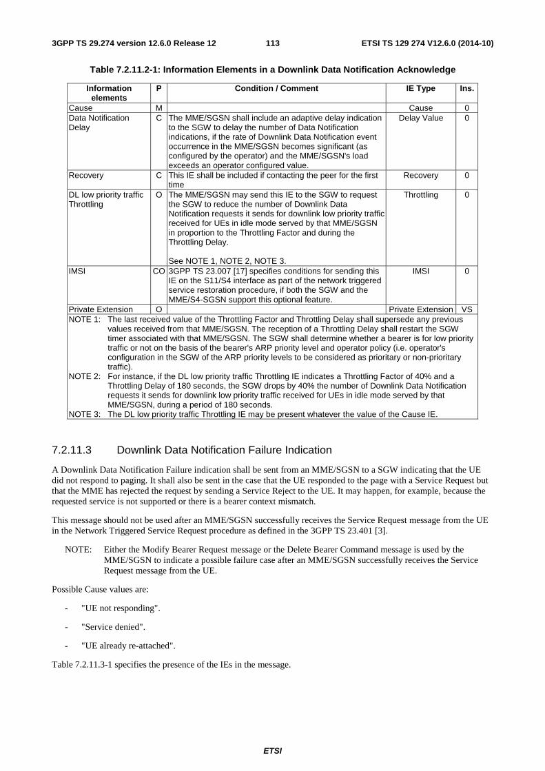
ETSI
ETSI TS 129 274 V12.6.0 (2014-10)1133GPP TS 29.274 version 12.6.0 Release 12
Table 7.2.11.2-1: Information Elements in a Downlink Data Notification Acknowledge
Information elements
P Condition / Comment IE Type Ins.
Cause M Cause 0 Data Notification Delay
C The MME/SGSN shall include an adaptive delay indication to the SGW to delay the number of Data Notification indications, if the rate of Downlink Data Notification event occurrence in the MME/SGSN becomes significant (as configured by the operator) and the MME/SGSN's load exceeds an operator configured value.
Delay Value 0
Recovery C This IE shall be included if contacting the peer for the first time
Recovery 0
DL low priority traffic Throttling
O The MME/SGSN may send this IE to the SGW to request the SGW to reduce the number of Downlink Data Notification requests it sends for downlink low priority traffic received for UEs in idle mode served by that MME/SGSN in proportion to the Throttling Factor and during the Throttling Delay. See NOTE 1, NOTE 2, NOTE 3.
Throttling 0
IMSI CO 3GPP TS 23.007 [17] specifies conditions for sending this IE on the S11/S4 interface as part of the network triggered service restoration procedure, if both the SGW and the MME/S4-SGSN support this optional feature.
IMSI 0
Private Extension O Private Extension VS NOTE 1: The last received value of the Throttling Factor and Throttling Delay shall supersede any previous
values received from that MME/SGSN. The reception of a Throttling Delay shall restart the SGW timer associated with that MME/SGSN. The SGW shall determine whether a bearer is for low priority traffic or not on the basis of the bearer's ARP priority level and operator policy (i.e. operator's configuration in the SGW of the ARP priority levels to be considered as prioritary or non-prioritary traffic).
NOTE 2: For instance, if the DL low priority traffic Throttling IE indicates a Throttling Factor of 40% and a Throttling Delay of 180 seconds, the SGW drops by 40% the number of Downlink Data Notification requests it sends for downlink low priority traffic received for UEs in idle mode served by that MME/SGSN, during a period of 180 seconds.
NOTE 3: The DL low priority traffic Throttling IE may be present whatever the value of the Cause IE.
7.2.11.3 Downlink Data Notification Failure Indication
A Downlink Data Notification Failure indication shall be sent from an MME/SGSN to a SGW indicating that the UE did not respond to paging. It shall also be sent in the case that the UE responded to the page with a Service Request but that the MME has rejected the request by sending a Service Reject to the UE. It may happen, for example, because the requested service is not supported or there is a bearer context mismatch.
This message should not be used after an MME/SGSN successfully receives the Service Request message from the UE in the Network Triggered Service Request procedure as defined in the 3GPP TS 23.401 [3].
NOTE: Either the Modify Bearer Request message or the Delete Bearer Command message is used by the MME/SGSN to indicate a possible failure case after an MME/SGSN successfully receives the Service Request message from the UE.
Possible Cause values are:
- "UE not responding".
- "Service denied".
- "UE already re-attached".
Table 7.2.11.3-1 specifies the presence of the IEs in the message.
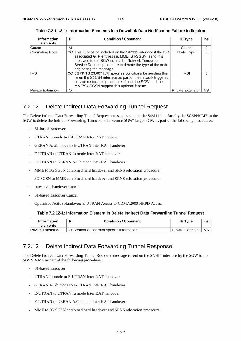
ETSI
ETSI TS 129 274 V12.6.0 (2014-10)1143GPP TS 29.274 version 12.6.0 Release 12
Table 7.2.11.3-1: Information Elements in a Downlink Data Notification Failure Indication
Information elements
P Condition / Comment IE Type Ins.
Cause M Cause 0 Originating Node CO This IE shall be included on the S4/S11 interface if the ISR
associated GTP entities i.e. MME, S4-SGSN, send this message to the SGW during the Network Triggered Service Request procedure to denote the type of the node originating the message.
Node Type 0
IMSI CO 3GPP TS 23.007 [17] specifies conditions for sending this IE on the S11/S4 interface as part of the network triggered service restoration procedure, if both the SGW and the MME/S4-SGSN support this optional feature.
IMSI 0
Private Extension O Private Extension VS
7.2.12 Delete Indirect Data Forwarding Tunnel Request
The Delete Indirect Data Forwarding Tunnel Request message is sent on the S4/S11 interface by the SGSN/MME to the SGW to delete the Indirect Forwarding Tunnels in the Source SGW/Target SGW as part of the following procedures:
- S1-based handover
- UTRAN Iu mode to E-UTRAN Inter RAT handover
- GERAN A/Gb mode to E-UTRAN Inter RAT handover
- E-UTRAN to UTRAN Iu mode Inter RAT handover
- E-UTRAN to GERAN A/Gb mode Inter RAT handover
- MME to 3G SGSN combined hard handover and SRNS relocation procedure
- 3G SGSN to MME combined hard handover and SRNS relocation procedure
- Inter RAT handover Cancel
- S1-based handover Cancel
- Optimised Active Handover: E-UTRAN Access to CDMA2000 HRPD Access
Table 7.2.12-1: Information Element in Delete Indirect Data Forwarding Tunnel Request
Information elements
P Condition / Comment IE Type Ins.
Private Extension O Vendor or operator specific information Private Extension VS
7.2.13 Delete Indirect Data Forwarding Tunnel Response
The Delete Indirect Data Forwarding Tunnel Response message is sent on the S4/S11 interface by the SGW to the SGSN/MME as part of the following procedures:
- S1-based handover
- UTRAN Iu mode to E-UTRAN Inter RAT handover
- GERAN A/Gb mode to E-UTRAN Inter RAT handover
- E-UTRAN to UTRAN Iu mode Inter RAT handover
- E-UTRAN to GERAN A/Gb mode Inter RAT handover
- MME to 3G SGSN combined hard handover and SRNS relocation procedure
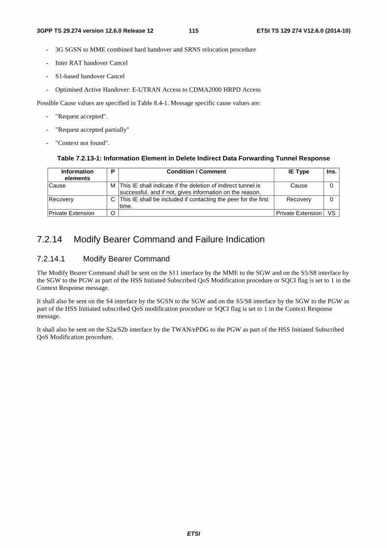
ETSI
ETSI TS 129 274 V12.6.0 (2014-10)1153GPP TS 29.274 version 12.6.0 Release 12
- 3G SGSN to MME combined hard handover and SRNS relocation procedure
- Inter RAT handover Cancel
- S1-based handover Cancel
- Optimised Active Handover: E-UTRAN Access to CDMA2000 HRPD Access
Possible Cause values are specified in Table 8.4-1. Message specific cause values are:
- "Request accepted".
- "Request accepted partially"
- "Context not found".
Table 7.2.13-1: Information Element in Delete Indirect Data Forwarding Tunnel Response
Information elements
P Condition / Comment IE Type Ins.
Cause M This IE shall indicate if the deletion of indirect tunnel is successful, and if not, gives information on the reason.
Cause 0
Recovery C This IE shall be included if contacting the peer for the first time.
Recovery 0
Private Extension O Private Extension VS
7.2.14 Modify Bearer Command and Failure Indication
7.2.14.1 Modify Bearer Command
The Modify Bearer Command shall be sent on the S11 interface by the MME to the SGW and on the S5/S8 interface by the SGW to the PGW as part of the HSS Initiated Subscribed QoS Modification procedure or SQCI flag is set to 1 in the Context Response message.
It shall also be sent on the S4 interface by the SGSN to the SGW and on the S5/S8 interface by the SGW to the PGW as part of the HSS Initiated subscribed QoS modification procedure or SQCI flag is set to 1 in the Context Response message.
It shall also be sent on the S2a/S2b interface by the TWAN/ePDG to the PGW as part of the HSS Initiated Subscribed QoS Modification procedure.
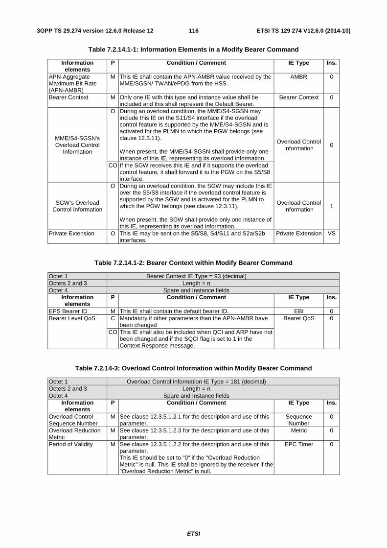
ETSI
ETSI TS 129 274 V12.6.0 (2014-10)1163GPP TS 29.274 version 12.6.0 Release 12
Table 7.2.14.1-1: Information Elements in a Modify Bearer Command
Information elements
P Condition / Comment IE Type Ins.
APN-Aggregate Maximum Bit Rate (APN-AMBR)
M This IE shall contain the APN-AMBR value received by the MME/SGSN/ TWAN/ePDG from the HSS.
AMBR 0
Bearer Context M Only one IE with this type and instance value shall be included and this shall represent the Default Bearer.
Bearer Context 0
MME/S4-SGSN's Overload Control
Information
O During an overload condition, the MME/S4-SGSN may include this IE on the S11/S4 interface if the overload control feature is supported by the MME/S4-SGSN and is activated for the PLMN to which the PGW belongs (see clause 12.3.11). When present, the MME/S4-SGSN shall provide only one instance of this IE, representing its overload information.
Overload Control Information 0
CO If the SGW receives this IE and if it supports the overload control feature, it shall forward it to the PGW on the S5/S8 interface.
SGW's Overload Control Information
O During an overload condition, the SGW may include this IE over the S5/S8 interface if the overload control feature is supported by the SGW and is activated for the PLMN to which the PGW belongs (see clause 12.3.11). When present, the SGW shall provide only one instance of this IE, representing its overload information.
Overload Control Information 1
Private Extension O This IE may be sent on the S5/S8, S4/S11 and S2a/S2b interfaces.
Private Extension VS
Table 7.2.14.1-2: Bearer Context within Modify Bearer Command
Octet 1 Bearer Context IE Type = 93 (decimal) Octets 2 and 3 Length = n Octet 4 Spare and Instance fields
Information elements
P Condition / Comment IE Type Ins.
EPS Bearer ID M This IE shall contain the default bearer ID. EBI 0 Bearer Level QoS C Mandatory if other parameters than the APN-AMBR have
been changed Bearer QoS 0
CO This IE shall also be included when QCI and ARP have not been changed and if the SQCI flag is set to 1 in the Context Response message.
Table 7.2.14-3: Overload Control Information within Modify Bearer Command
Octet 1 Overload Control Information IE Type = 181 (decimal) Octets 2 and 3 Length = n Octet 4 Spare and Instance fields
Information elements
P Condition / Comment IE Type Ins.
Overload Control Sequence Number
M See clause 12.3.5.1.2.1 for the description and use of this parameter.
Sequence Number
0
Overload Reduction Metric
M See clause 12.3.5.1.2.3 for the description and use of this parameter.
Metric 0
Period of Validity M See clause 12.3.5.1.2.2 for the description and use of this parameter. This IE should be set to "0" if the "Overload Reduction Metric" is null. This IE shall be ignored by the receiver if the "Overload Reduction Metric" is null.
EPC Timer 0
ETSI
ETSI TS 129 274 V12.6.0 (2014-10)1173GPP TS 29.274 version 12.6.0 Release 12
7.2.14.2 Modify Bearer Failure Indication
The Modify Bearer Failure Indication shall be sent on the S5/S8 interface by the PGW to the SGW and on the S11 interface by the SGW to the MME as part of failure of HSS Initiated Subscribed QoS Modification procedure or SQCI flag is set to 1 in the Context Response message.
It shall also be sent on the S5/S8 interface by the PGW to the SGW and on the S4 interface by the SGW to the SGSN as part of failure of HSS Initiated subscribed QoS modification or SQCI flag is set to 1 in the Context Response message.
It shall also be sent on the S2a/S2b interface by the PGW to the TWAN/ePDG as part of failure of HSS Initiated Subscribed QoS Modification procedure.
Cause IE indicates that an EPS bearer has not been updated in the PGW.
Possible Cause values are specified in Table 8.4-1. Message specific cause values are:
- "Context not found"
- "Service denied".
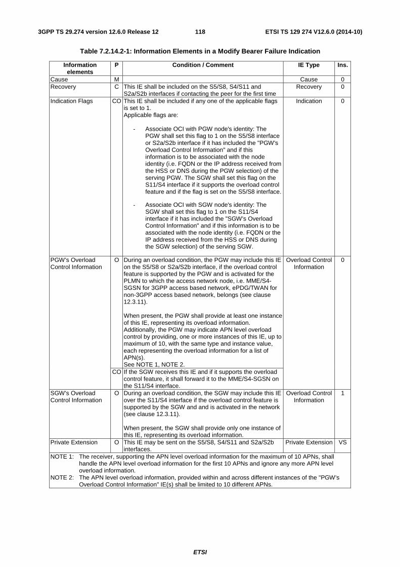
ETSI
ETSI TS 129 274 V12.6.0 (2014-10)1183GPP TS 29.274 version 12.6.0 Release 12
Table 7.2.14.2-1: Information Elements in a Modify Bearer Failure Indication
Information elements
P Condition / Comment IE Type Ins.
Cause M Cause 0 Recovery C This IE shall be included on the S5/S8, S4/S11 and
S2a/S2b interfaces if contacting the peer for the first time Recovery 0
Indication Flags CO This IE shall be included if any one of the applicable flags is set to 1. Applicable flags are:
- Associate OCI with PGW node's identity: The PGW shall set this flag to 1 on the S5/S8 interface or S2a/S2b interface if it has included the "PGW's Overload Control Information" and if this information is to be associated with the node identity (i.e. FQDN or the IP address received from the HSS or DNS during the PGW selection) of the serving PGW. The SGW shall set this flag on the S11/S4 interface if it supports the overload control feature and if the flag is set on the S5/S8 interface.
- Associate OCI with SGW node's identity: The SGW shall set this flag to 1 on the S11/S4 interface if it has included the "SGW's Overload Control Information" and if this information is to be associated with the node identity (i.e. FQDN or the IP address received from the HSS or DNS during the SGW selection) of the serving SGW.
Indication 0
PGW's Overload Control Information
O During an overload condition, the PGW may include this IE on the S5/S8 or S2a/S2b interface, if the overload control feature is supported by the PGW and is activated for the PLMN to which the access network node, i.e. MME/S4-SGSN for 3GPP access based network, ePDG/TWAN for non-3GPP access based network, belongs (see clause 12.3.11). When present, the PGW shall provide at least one instance of this IE, representing its overload information. Additionally, the PGW may indicate APN level overload control by providing, one or more instances of this IE, up to maximum of 10, with the same type and instance value, each representing the overload information for a list of APN(s). See NOTE 1, NOTE 2.
Overload Control Information
0
CO If the SGW receives this IE and if it supports the overload control feature, it shall forward it to the MME/S4-SGSN on the S11/S4 interface.
SGW's Overload Control Information
O During an overload condition, the SGW may include this IE over the S11/S4 interface if the overload control feature is supported by the SGW and and is activated in the network (see clause 12.3.11). When present, the SGW shall provide only one instance of this IE, representing its overload information.
Overload Control Information
1
Private Extension O This IE may be sent on the S5/S8, S4/S11 and S2a/S2b interfaces.
Private Extension VS
NOTE 1: The receiver, supporting the APN level overload information for the maximum of 10 APNs, shall handle the APN level overload information for the first 10 APNs and ignore any more APN level overload information.
NOTE 2: The APN level overload information, provided within and across different instances of the "PGW's Overload Control Information" IE(s) shall be limited to 10 different APNs.
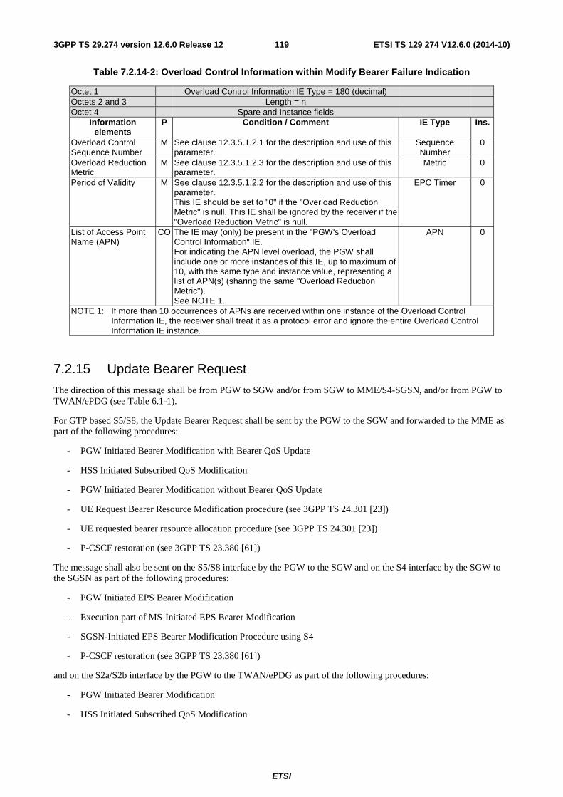
ETSI
ETSI TS 129 274 V12.6.0 (2014-10)1193GPP TS 29.274 version 12.6.0 Release 12
Table 7.2.14-2: Overload Control Information within Modify Bearer Failure Indication
Octet 1 Overload Control Information IE Type = 180 (decimal) Octets 2 and 3 Length = n Octet 4 Spare and Instance fields
Information elements
P Condition / Comment IE Type Ins.
Overload Control Sequence Number
M See clause 12.3.5.1.2.1 for the description and use of this parameter.
Sequence Number
0
Overload Reduction Metric
M See clause 12.3.5.1.2.3 for the description and use of this parameter.
Metric 0
Period of Validity M See clause 12.3.5.1.2.2 for the description and use of this parameter. This IE should be set to "0" if the "Overload Reduction Metric" is null. This IE shall be ignored by the receiver if the "Overload Reduction Metric" is null.
EPC Timer 0
List of Access Point Name (APN)
CO The IE may (only) be present in the "PGW's Overload Control Information" IE. For indicating the APN level overload, the PGW shall include one or more instances of this IE, up to maximum of 10, with the same type and instance value, representing a list of APN(s) (sharing the same "Overload Reduction Metric"). See NOTE 1.
APN 0
NOTE 1: If more than 10 occurrences of APNs are received within one instance of the Overload Control Information IE, the receiver shall treat it as a protocol error and ignore the entire Overload Control Information IE instance.
7.2.15 Update Bearer Request
The direction of this message shall be from PGW to SGW and/or from SGW to MME/S4-SGSN, and/or from PGW to TWAN/ePDG (see Table 6.1-1).
For GTP based S5/S8, the Update Bearer Request shall be sent by the PGW to the SGW and forwarded to the MME as part of the following procedures:
- PGW Initiated Bearer Modification with Bearer QoS Update
- HSS Initiated Subscribed QoS Modification
- PGW Initiated Bearer Modification without Bearer QoS Update
- UE Request Bearer Resource Modification procedure (see 3GPP TS 24.301 [23])
- UE requested bearer resource allocation procedure (see 3GPP TS 24.301 [23])
- P-CSCF restoration (see 3GPP TS 23.380 [61])
The message shall also be sent on the S5/S8 interface by the PGW to the SGW and on the S4 interface by the SGW to the SGSN as part of the following procedures:
- PGW Initiated EPS Bearer Modification
- Execution part of MS-Initiated EPS Bearer Modification
- SGSN-Initiated EPS Bearer Modification Procedure using S4
- P-CSCF restoration (see 3GPP TS 23.380 [61])
and on the S2a/S2b interface by the PGW to the TWAN/ePDG as part of the following procedures:
- PGW Initiated Bearer Modification
- HSS Initiated Subscribed QoS Modification

ETSI
ETSI TS 129 274 V12.6.0 (2014-10)1203GPP TS 29.274 version 12.6.0 Release 12
For PMIP based S5/S8, the Update Bearer Request shall be sent on the S11 interface by the SGW to the MME and on the S4 interface by the SGW to the SGSN.
Table 7.2.15-1 specifies the presence requirements and the conditions of the IEs in the message.
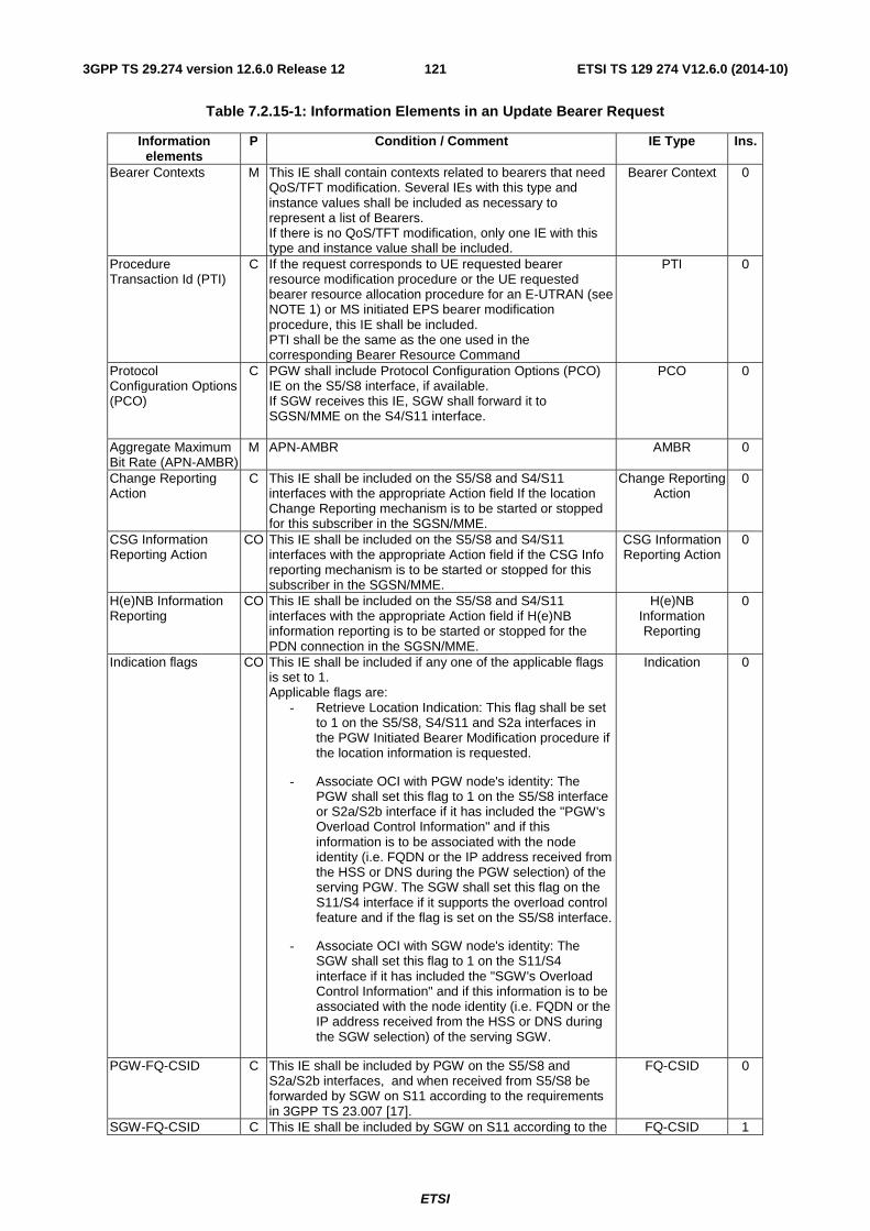
ETSI
ETSI TS 129 274 V12.6.0 (2014-10)1213GPP TS 29.274 version 12.6.0 Release 12
Table 7.2.15-1: Information Elements in an Update Bearer Request
Information elements
P Condition / Comment IE Type Ins.
Bearer Contexts M This IE shall contain contexts related to bearers that need QoS/TFT modification. Several IEs with this type and instance values shall be included as necessary to represent a list of Bearers. If there is no QoS/TFT modification, only one IE with this type and instance value shall be included.
Bearer Context 0
Procedure Transaction Id (PTI)
C If the request corresponds to UE requested bearer resource modification procedure or the UE requested bearer resource allocation procedure for an E-UTRAN (see NOTE 1) or MS initiated EPS bearer modification procedure, this IE shall be included. PTI shall be the same as the one used in the corresponding Bearer Resource Command
PTI 0
Protocol Configuration Options (PCO)
C PGW shall include Protocol Configuration Options (PCO) IE on the S5/S8 interface, if available. If SGW receives this IE, SGW shall forward it to SGSN/MME on the S4/S11 interface.
PCO 0
Aggregate Maximum Bit Rate (APN-AMBR)
M APN-AMBR AMBR 0
Change Reporting Action
C This IE shall be included on the S5/S8 and S4/S11 interfaces with the appropriate Action field If the location Change Reporting mechanism is to be started or stopped for this subscriber in the SGSN/MME.
Change Reporting Action
0
CSG Information Reporting Action
CO This IE shall be included on the S5/S8 and S4/S11 interfaces with the appropriate Action field if the CSG Info reporting mechanism is to be started or stopped for this subscriber in the SGSN/MME.
CSG Information Reporting Action
0
H(e)NB Information Reporting
CO This IE shall be included on the S5/S8 and S4/S11 interfaces with the appropriate Action field if H(e)NB information reporting is to be started or stopped for the PDN connection in the SGSN/MME.
H(e)NB Information Reporting
0
Indication flags CO This IE shall be included if any one of the applicable flags is set to 1. Applicable flags are:
- Retrieve Location Indication: This flag shall be set to 1 on the S5/S8, S4/S11 and S2a interfaces in the PGW Initiated Bearer Modification procedure if the location information is requested.
- Associate OCI with PGW node's identity: The PGW shall set this flag to 1 on the S5/S8 interface or S2a/S2b interface if it has included the "PGW's Overload Control Information" and if this information is to be associated with the node identity (i.e. FQDN or the IP address received from the HSS or DNS during the PGW selection) of the serving PGW. The SGW shall set this flag on the S11/S4 interface if it supports the overload control feature and if the flag is set on the S5/S8 interface.
- Associate OCI with SGW node's identity: The SGW shall set this flag to 1 on the S11/S4 interface if it has included the "SGW's Overload Control Information" and if this information is to be associated with the node identity (i.e. FQDN or the IP address received from the HSS or DNS during the SGW selection) of the serving SGW.
Indication 0
PGW-FQ-CSID C This IE shall be included by PGW on the S5/S8 and S2a/S2b interfaces, and when received from S5/S8 be forwarded by SGW on S11 according to the requirements in 3GPP TS 23.007 [17].
FQ-CSID 0
SGW-FQ-CSID C This IE shall be included by SGW on S11 according to the FQ-CSID 1
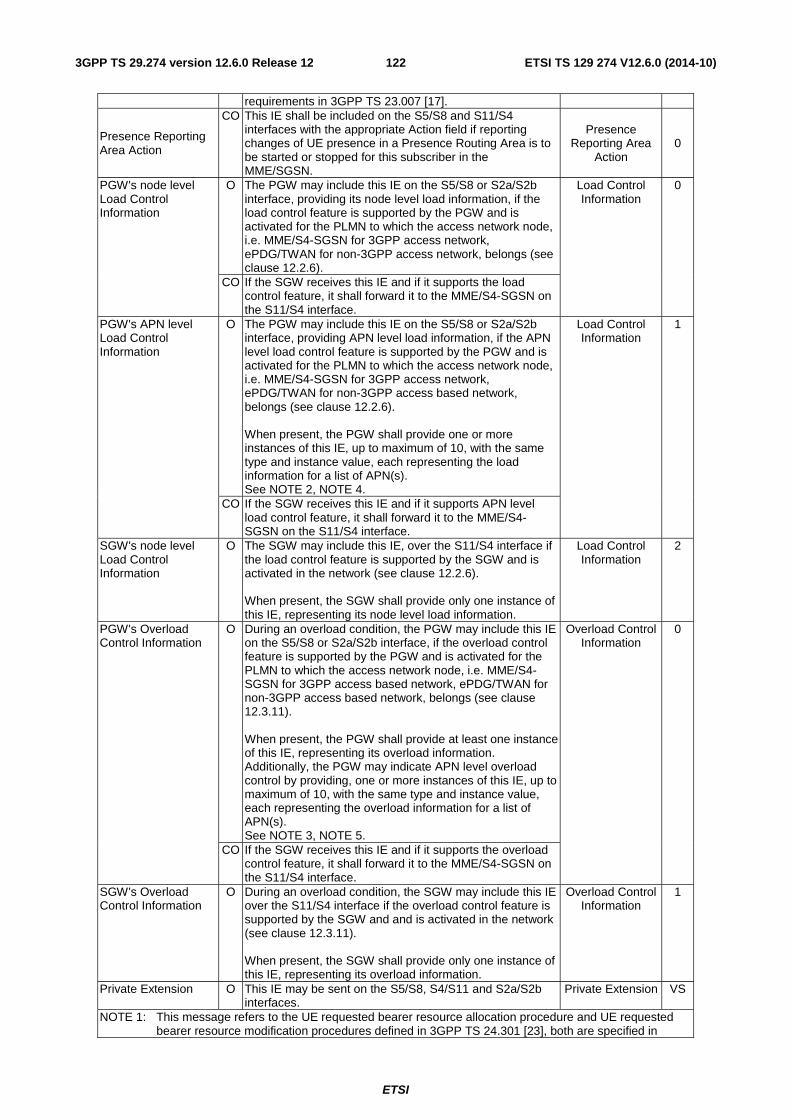
ETSI
ETSI TS 129 274 V12.6.0 (2014-10)1223GPP TS 29.274 version 12.6.0 Release 12
requirements in 3GPP TS 23.007 [17].
Presence Reporting Area Action
CO This IE shall be included on the S5/S8 and S11/S4 interfaces with the appropriate Action field if reporting changes of UE presence in a Presence Routing Area is to be started or stopped for this subscriber in the MME/SGSN.
Presence Reporting Area
Action 0
PGW's node level Load Control Information
O The PGW may include this IE on the S5/S8 or S2a/S2b interface, providing its node level load information, if the load control feature is supported by the PGW and is activated for the PLMN to which the access network node, i.e. MME/S4-SGSN for 3GPP access network, ePDG/TWAN for non-3GPP access network, belongs (see clause 12.2.6).
Load Control Information
0
CO If the SGW receives this IE and if it supports the load control feature, it shall forward it to the MME/S4-SGSN on the S11/S4 interface.
PGW's APN level Load Control Information
O The PGW may include this IE on the S5/S8 or S2a/S2b interface, providing APN level load information, if the APN level load control feature is supported by the PGW and is activated for the PLMN to which the access network node, i.e. MME/S4-SGSN for 3GPP access network, ePDG/TWAN for non-3GPP access based network, belongs (see clause 12.2.6). When present, the PGW shall provide one or more instances of this IE, up to maximum of 10, with the same type and instance value, each representing the load information for a list of APN(s). See NOTE 2, NOTE 4.
Load Control Information
1
CO If the SGW receives this IE and if it supports APN level load control feature, it shall forward it to the MME/S4-SGSN on the S11/S4 interface.
SGW's node level Load Control Information
O The SGW may include this IE, over the S11/S4 interface if the load control feature is supported by the SGW and is activated in the network (see clause 12.2.6). When present, the SGW shall provide only one instance of this IE, representing its node level load information.
Load Control Information
2
PGW's Overload Control Information
O During an overload condition, the PGW may include this IE on the S5/S8 or S2a/S2b interface, if the overload control feature is supported by the PGW and is activated for the PLMN to which the access network node, i.e. MME/S4-SGSN for 3GPP access based network, ePDG/TWAN for non-3GPP access based network, belongs (see clause 12.3.11). When present, the PGW shall provide at least one instance of this IE, representing its overload information. Additionally, the PGW may indicate APN level overload control by providing, one or more instances of this IE, up to maximum of 10, with the same type and instance value, each representing the overload information for a list of APN(s). See NOTE 3, NOTE 5.
Overload Control Information
0
CO If the SGW receives this IE and if it supports the overload control feature, it shall forward it to the MME/S4-SGSN on the S11/S4 interface.
SGW's Overload Control Information
O During an overload condition, the SGW may include this IE over the S11/S4 interface if the overload control feature is supported by the SGW and and is activated in the network (see clause 12.3.11). When present, the SGW shall provide only one instance of this IE, representing its overload information.
Overload Control Information
1
Private Extension O This IE may be sent on the S5/S8, S4/S11 and S2a/S2b interfaces.
Private Extension VS
NOTE 1: This message refers to the UE requested bearer resource allocation procedure and UE requested bearer resource modification procedures defined in 3GPP TS 24.301 [23], both are specified in
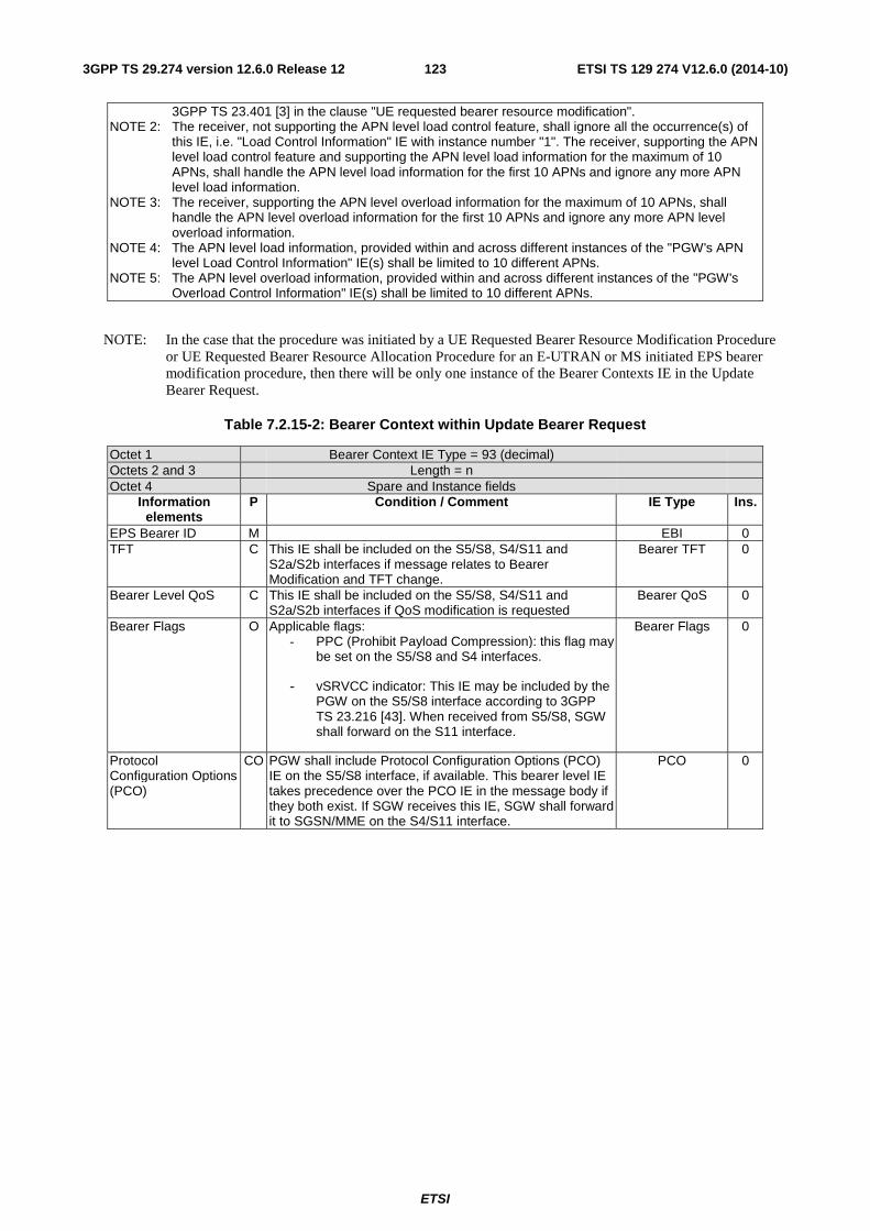
ETSI
ETSI TS 129 274 V12.6.0 (2014-10)1233GPP TS 29.274 version 12.6.0 Release 12
3GPP TS 23.401 [3] in the clause "UE requested bearer resource modification". NOTE 2: The receiver, not supporting the APN level load control feature, shall ignore all the occurrence(s) of
this IE, i.e. "Load Control Information" IE with instance number "1". The receiver, supporting the APN level load control feature and supporting the APN level load information for the maximum of 10 APNs, shall handle the APN level load information for the first 10 APNs and ignore any more APN level load information.
NOTE 3: The receiver, supporting the APN level overload information for the maximum of 10 APNs, shall handle the APN level overload information for the first 10 APNs and ignore any more APN level overload information.
NOTE 4: The APN level load information, provided within and across different instances of the "PGW's APN level Load Control Information" IE(s) shall be limited to 10 different APNs.
NOTE 5: The APN level overload information, provided within and across different instances of the "PGW's Overload Control Information" IE(s) shall be limited to 10 different APNs.
NOTE: In the case that the procedure was initiated by a UE Requested Bearer Resource Modification Procedure or UE Requested Bearer Resource Allocation Procedure for an E-UTRAN or MS initiated EPS bearer modification procedure, then there will be only one instance of the Bearer Contexts IE in the Update Bearer Request.
Table 7.2.15-2: Bearer Context within Update Bearer Request
Octet 1 Bearer Context IE Type = 93 (decimal) Octets 2 and 3 Length = n Octet 4 Spare and Instance fields
Information elements
P Condition / Comment IE Type Ins.
EPS Bearer ID M EBI 0 TFT C This IE shall be included on the S5/S8, S4/S11 and
S2a/S2b interfaces if message relates to Bearer Modification and TFT change.
Bearer TFT 0
Bearer Level QoS C This IE shall be included on the S5/S8, S4/S11 and S2a/S2b interfaces if QoS modification is requested
Bearer QoS 0
Bearer Flags O Applicable flags: - PPC (Prohibit Payload Compression): this flag may
be set on the S5/S8 and S4 interfaces.
- vSRVCC indicator: This IE may be included by the PGW on the S5/S8 interface according to 3GPP TS 23.216 [43]. When received from S5/S8, SGW shall forward on the S11 interface.
Bearer Flags 0
Protocol Configuration Options (PCO)
CO PGW shall include Protocol Configuration Options (PCO) IE on the S5/S8 interface, if available. This bearer level IE takes precedence over the PCO IE in the message body if they both exist. If SGW receives this IE, SGW shall forward it to SGSN/MME on the S4/S11 interface.
PCO 0
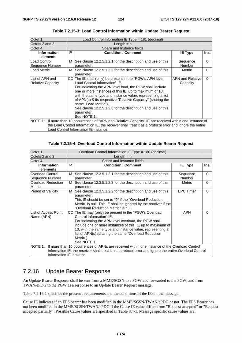
ETSI
ETSI TS 129 274 V12.6.0 (2014-10)1243GPP TS 29.274 version 12.6.0 Release 12
Table 7.2.15-3: Load Control Information within Update Bearer Request
Octet 1 Load Control Information IE Type = 181 (decimal) Octets 2 and 3 Length = n Octet 4 Spare and Instance fields
Information elements
P Condition / Comment IE Type Ins.
Load Control Sequence Number
M See clause 12.2.5.1.2.1 for the description and use of this parameter.
Sequence Number
0
Load Metric M See clause 12.2.5.1.2.2 for the description and use of this parameter.
Metric 0
List of APN and Relative Capacity
CO The IE shall (only) be present in the "PGW's APN level Load Control Information" IE. For indicating the APN level load, the PGW shall include one or more instances of this IE, up to maximum of 10, with the same type and instance value, representing a list of APN(s) & its respective "Relative Capacity" (sharing the same "Load Metric"). See clause 12.2.5.1.2.3 for the description and use of this parameter. See NOTE 1.
APN and Relative Capacity
0
NOTE 1: If more than 10 occurrences of "APN and Relative Capacity" IE are received within one instance of the Load Control Information IE, the receiver shall treat it as a protocol error and ignore the entire Load Control Information IE instance.
Table 7.2.15-4: Overload Control Information within Update Bearer Request
Octet 1 Overload Control Information IE Type = 180 (decimal) Octets 2 and 3 Length = n Octet 4 Spare and Instance fields
Information elements
P Condition / Comment IE Type Ins.
Overload Control Sequence Number
M See clause 12.3.5.1.2.1 for the description and use of this parameter.
Sequence Number
0
Overload Reduction Metric
M See clause 12.3.5.1.2.3 for the description and use of this parameter.
Metric 0
Period of Validity M See clause 12.3.5.1.2.2 for the description and use of this parameter. This IE should be set to "0" if the "Overload Reduction Metric" is null. This IE shall be ignored by the receiver if the "Overload Reduction Metric" is null.
EPC Timer 0
List of Access Point Name (APN)
CO The IE may (only) be present in the "PGW's Overload Control Information" IE. For indicating the APN level overload, the PGW shall include one or more instances of this IE, up to maximum of 10, with the same type and instance value, representing a list of APN(s) (sharing the same "Overload Reduction Metric"). See NOTE 1.
APN 0
NOTE 1: If more than 10 occurrences of APNs are received within one instance of the Overload Control Information IE, the receiver shall treat it as a protocol error and ignore the entire Overload Control Information IE instance.
7.2.16 Update Bearer Response
An Update Bearer Response shall be sent from a MME/SGSN to a SGW and forwarded to the PGW, and from TWAN/ePDG to the PGW as a response to an Update Bearer Request message.
Table 7.2.16-1 specifies the presence requirements and the conditions of the IEs in the message.
Cause IE indicates if an EPS bearer has been modified in the MME/SGSN/TWAN/ePDG or not. The EPS Bearer has not been modified in the MME/SGSN/TWAN/ePDG if the Cause IE value differs from "Request accepted" or "Request accepted partially". Possible Cause values are specified in Table 8.4-1. Message specific cause values are:
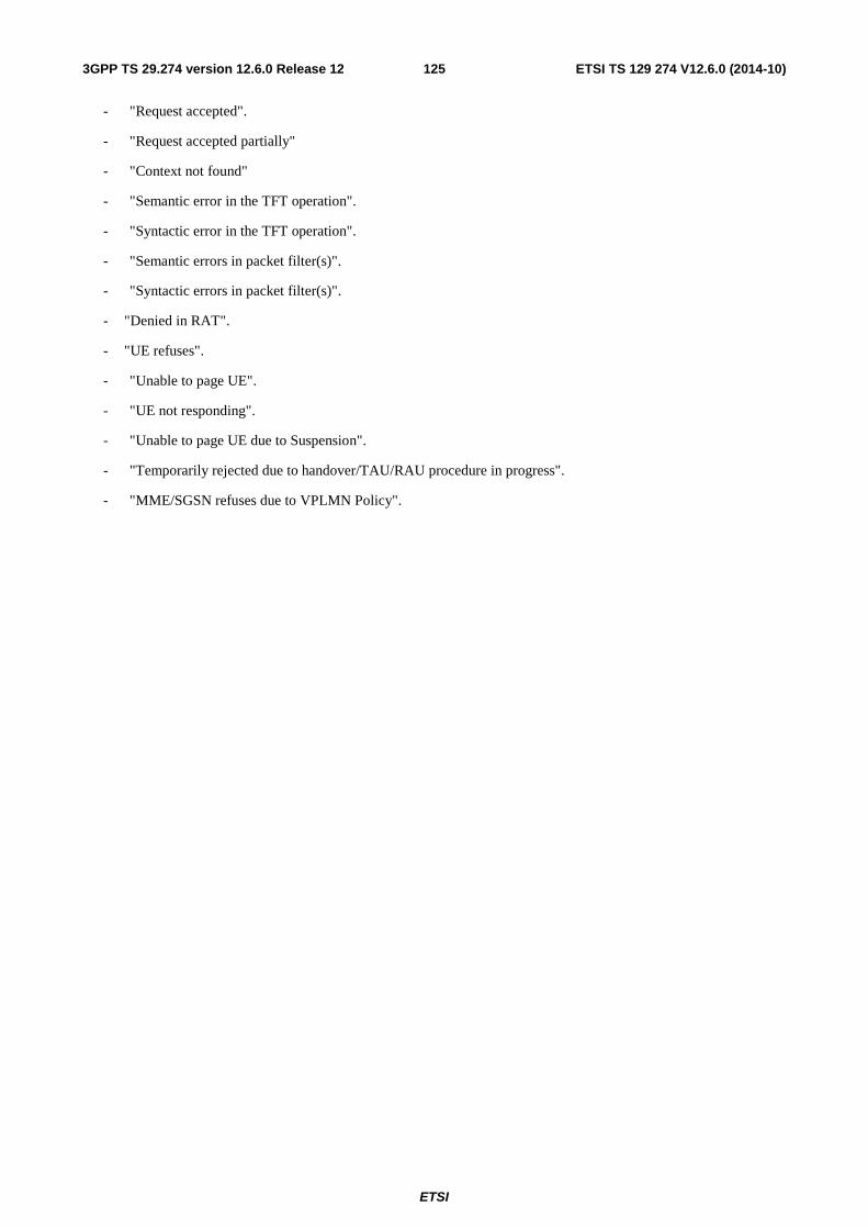
ETSI
ETSI TS 129 274 V12.6.0 (2014-10)1253GPP TS 29.274 version 12.6.0 Release 12
- "Request accepted".
- "Request accepted partially"
- "Context not found"
- "Semantic error in the TFT operation".
- "Syntactic error in the TFT operation".
- "Semantic errors in packet filter(s)".
- "Syntactic errors in packet filter(s)".
- "Denied in RAT".
- "UE refuses".
- "Unable to page UE".
- "UE not responding".
- "Unable to page UE due to Suspension".
- "Temporarily rejected due to handover/TAU/RAU procedure in progress".
- "MME/SGSN refuses due to VPLMN Policy".
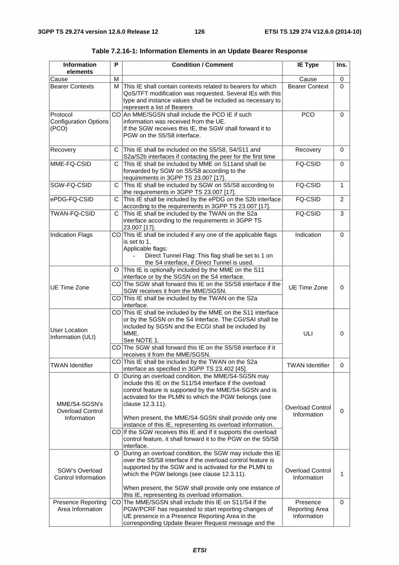
ETSI
ETSI TS 129 274 V12.6.0 (2014-10)1263GPP TS 29.274 version 12.6.0 Release 12
Table 7.2.16-1: Information Elements in an Update Bearer Response
Information elements
P Condition / Comment IE Type Ins.
Cause M Cause 0 Bearer Contexts M This IE shall contain contexts related to bearers for which
QoS/TFT modification was requested. Several IEs with this type and instance values shall be included as necessary to represent a list of Bearers
Bearer Context 0
Protocol Configuration Options (PCO)
CO An MME/SGSN shall include the PCO IE if such information was received from the UE. If the SGW receives this IE, the SGW shall forward it to PGW on the S5/S8 interface.
PCO 0
Recovery C This IE shall be included on the S5/S8, S4/S11 and S2a/S2b interfaces if contacting the peer for the first time
Recovery 0
MME-FQ-CSID C This IE shall be included by MME on S11and shall be forwarded by SGW on S5/S8 according to the requirements in 3GPP TS 23.007 [17].
FQ-CSID 0
SGW-FQ-CSID C This IE shall be included by SGW on S5/S8 according to the requirements in 3GPP TS 23.007 [17].
FQ-CSID 1
ePDG-FQ-CSID C This IE shall be included by the ePDG on the S2b interface according to the requirements in 3GPP TS 23.007 [17].
FQ-CSID 2
TWAN-FQ-CSID C This IE shall be included by the TWAN on the S2a interface according to the requirements in 3GPP TS 23.007 [17].
FQ-CSID 3
Indication Flags CO This IE shall be included if any one of the applicable flags is set to 1. Applicable flags:
- Direct Tunnel Flag: This flag shall be set to 1 on the S4 interface, if Direct Tunnel is used.
Indication 0
UE Time Zone
O This IE is optionally included by the MME on the S11 interface or by the SGSN on the S4 interface.
UE Time Zone 0 CO The SGW shall forward this IE on the S5/S8 interface if the SGW receives it from the MME/SGSN.
CO This IE shall be included by the TWAN on the S2a interface.
User Location Information (ULI)
CO This IE shall be included by the MME on the S11 interface or by the SGSN on the S4 interface. The CGI/SAI shall be included by SGSN and the ECGI shall be included by MME. See NOTE 1.
ULI 0
CO The SGW shall forward this IE on the S5/S8 interface if it receives it from the MME/SGSN.
TWAN Identifier CO This IE shall be included by the TWAN on the S2a interface as specified in 3GPP TS 23.402 [45]. TWAN Identifier 0
MME/S4-SGSN's Overload Control
Information
O During an overload condition, the MME/S4-SGSN may include this IE on the S11/S4 interface if the overload control feature is supported by the MME/S4-SGSN and is activated for the PLMN to which the PGW belongs (see clause 12.3.11). When present, the MME/S4-SGSN shall provide only one instance of this IE, representing its overload information.
Overload Control Information 0
CO If the SGW receives this IE and if it supports the overload control feature, it shall forward it to the PGW on the S5/S8 interface.
SGW's Overload Control Information
O During an overload condition, the SGW may include this IE over the S5/S8 interface if the overload control feature is supported by the SGW and is activated for the PLMN to which the PGW belongs (see clause 12.3.11). When present, the SGW shall provide only one instance of this IE, representing its overload information.
Overload Control Information
1
Presence Reporting Area Information
CO The MME/SGSN shall include this IE on S11/S4 if the PGW/PCRF has requested to start reporting changes of UE presence in a Presence Reporting Area in the corresponding Update Bearer Request message and the
Presence Reporting Area
Information
0
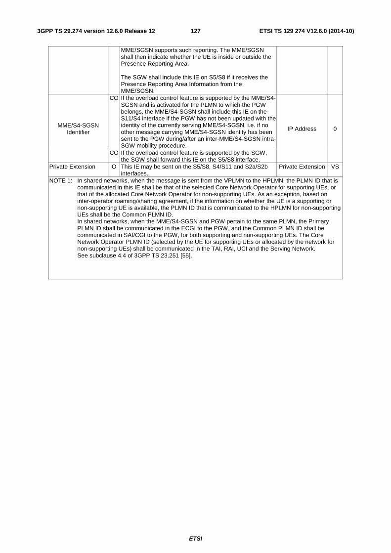
ETSI
ETSI TS 129 274 V12.6.0 (2014-10)1273GPP TS 29.274 version 12.6.0 Release 12
MME/SGSN supports such reporting. The MME/SGSN shall then indicate whether the UE is inside or outside the Presence Reporting Area. The SGW shall include this IE on S5/S8 if it receives the Presence Reporting Area Information from the MME/SGSN.
MME/S4-SGSN Identifier
CO If the overload control feature is supported by the MME/S4-SGSN and is activated for the PLMN to which the PGW belongs, the MME/S4-SGSN shall include this IE on the S11/S4 interface if the PGW has not been updated with the identity of the currently serving MME/S4-SGSN, i.e. if no other message carrying MME/S4-SGSN identity has been sent to the PGW during/after an inter-MME/S4-SGSN intra-SGW mobility procedure.
IP Address 0
CO If the overload control feature is supported by the SGW, the SGW shall forward this IE on the S5/S8 interface.
Private Extension O This IE may be sent on the S5/S8, S4/S11 and S2a/S2b interfaces.
Private Extension VS
NOTE 1: In shared networks, when the message is sent from the VPLMN to the HPLMN, the PLMN ID that is communicated in this IE shall be that of the selected Core Network Operator for supporting UEs, or that of the allocated Core Network Operator for non-supporting UEs. As an exception, based on inter-operator roaming/sharing agreement, if the information on whether the UE is a supporting or non-supporting UE is available, the PLMN ID that is communicated to the HPLMN for non-supporting UEs shall be the Common PLMN ID. In shared networks, when the MME/S4-SGSN and PGW pertain to the same PLMN, the Primary PLMN ID shall be communicated in the ECGI to the PGW, and the Common PLMN ID shall be communicated in SAI/CGI to the PGW, for both supporting and non-supporting UEs. The Core Network Operator PLMN ID (selected by the UE for supporting UEs or allocated by the network for non-supporting UEs) shall be communicated in the TAI, RAI, UCI and the Serving Network. See subclause 4.4 of 3GPP TS 23.251 [55].
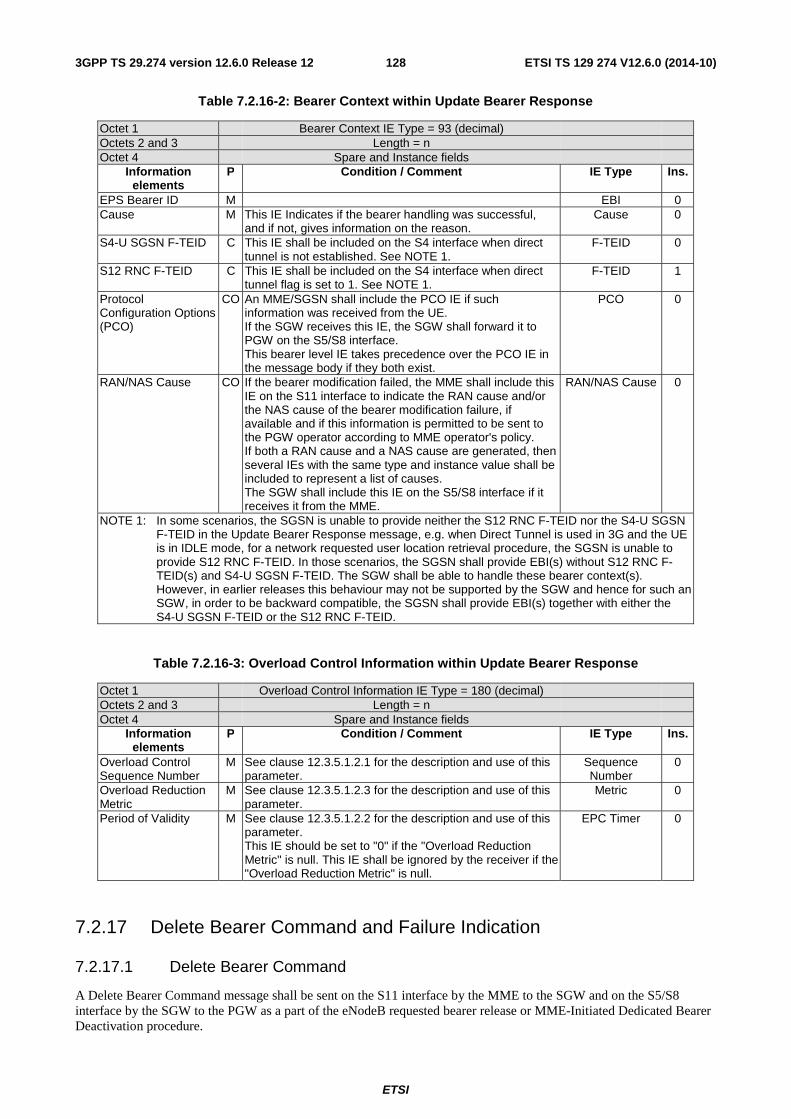
ETSI
ETSI TS 129 274 V12.6.0 (2014-10)1283GPP TS 29.274 version 12.6.0 Release 12
Table 7.2.16-2: Bearer Context within Update Bearer Response
Octet 1 Bearer Context IE Type = 93 (decimal) Octets 2 and 3 Length = n Octet 4 Spare and Instance fields
Information elements
P Condition / Comment IE Type Ins.
EPS Bearer ID M EBI 0 Cause M This IE Indicates if the bearer handling was successful,
and if not, gives information on the reason. Cause 0
S4-U SGSN F-TEID C This IE shall be included on the S4 interface when direct tunnel is not established. See NOTE 1.
F-TEID 0
S12 RNC F-TEID C This IE shall be included on the S4 interface when direct tunnel flag is set to 1. See NOTE 1.
F-TEID 1
Protocol Configuration Options (PCO)
CO An MME/SGSN shall include the PCO IE if such information was received from the UE. If the SGW receives this IE, the SGW shall forward it to PGW on the S5/S8 interface. This bearer level IE takes precedence over the PCO IE in the message body if they both exist.
PCO 0
RAN/NAS Cause CO
If the bearer modification failed, the MME shall include this IE on the S11 interface to indicate the RAN cause and/or the NAS cause of the bearer modification failure, if available and if this information is permitted to be sent to the PGW operator according to MME operator's policy. If both a RAN cause and a NAS cause are generated, then several IEs with the same type and instance value shall be included to represent a list of causes. The SGW shall include this IE on the S5/S8 interface if it receives it from the MME.
RAN/NAS Cause 0
NOTE 1: In some scenarios, the SGSN is unable to provide neither the S12 RNC F-TEID nor the S4-U SGSN F-TEID in the Update Bearer Response message, e.g. when Direct Tunnel is used in 3G and the UE is in IDLE mode, for a network requested user location retrieval procedure, the SGSN is unable to provide S12 RNC F-TEID. In those scenarios, the SGSN shall provide EBI(s) without S12 RNC F-TEID(s) and S4-U SGSN F-TEID. The SGW shall be able to handle these bearer context(s). However, in earlier releases this behaviour may not be supported by the SGW and hence for such an SGW, in order to be backward compatible, the SGSN shall provide EBI(s) together with either the S4-U SGSN F-TEID or the S12 RNC F-TEID.
Table 7.2.16-3: Overload Control Information within Update Bearer Response
Octet 1 Overload Control Information IE Type = 180 (decimal) Octets 2 and 3 Length = n Octet 4 Spare and Instance fields
Information elements
P Condition / Comment IE Type Ins.
Overload Control Sequence Number
M See clause 12.3.5.1.2.1 for the description and use of this parameter.
Sequence Number
0
Overload Reduction Metric
M See clause 12.3.5.1.2.3 for the description and use of this parameter.
Metric 0
Period of Validity M See clause 12.3.5.1.2.2 for the description and use of this parameter. This IE should be set to "0" if the "Overload Reduction Metric" is null. This IE shall be ignored by the receiver if the "Overload Reduction Metric" is null.
EPC Timer 0
7.2.17 Delete Bearer Command and Failure Indication
7.2.17.1 Delete Bearer Command
A Delete Bearer Command message shall be sent on the S11 interface by the MME to the SGW and on the S5/S8 interface by the SGW to the PGW as a part of the eNodeB requested bearer release or MME-Initiated Dedicated Bearer Deactivation procedure.
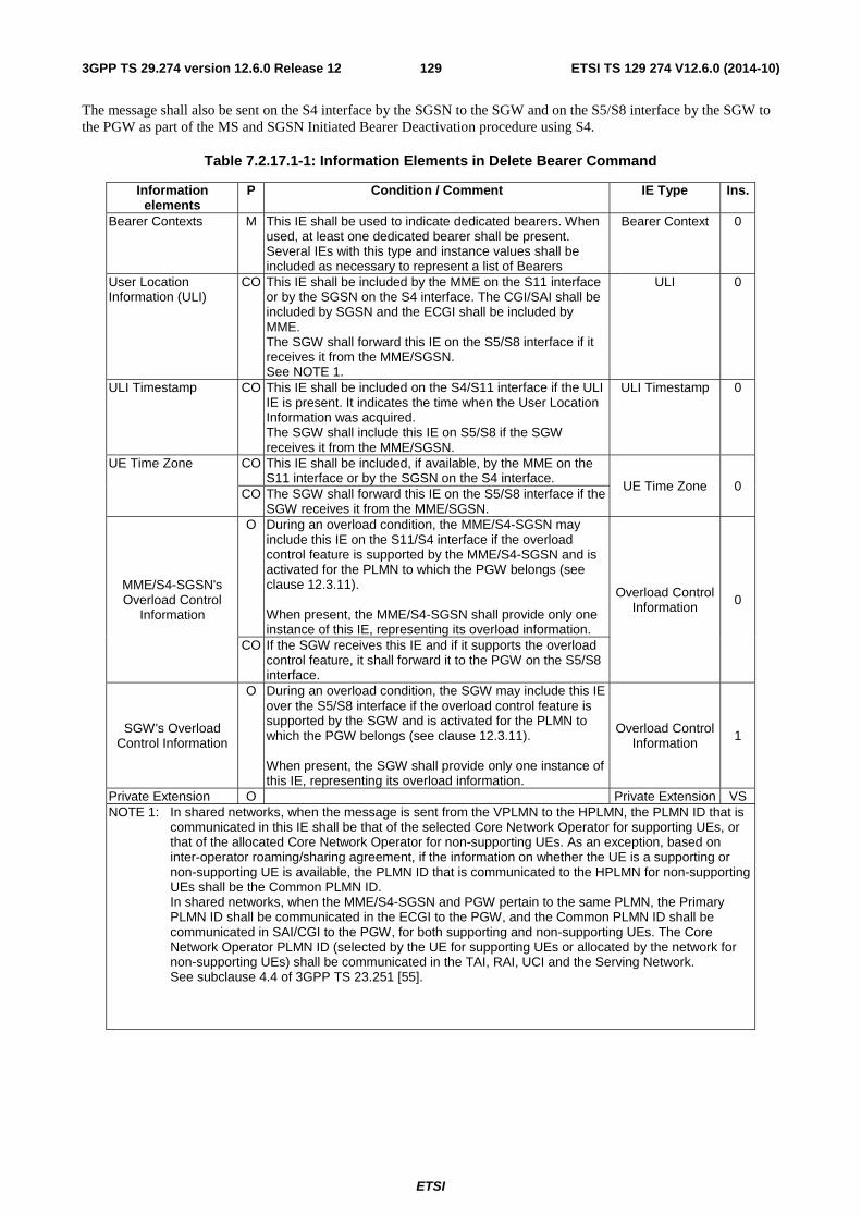
ETSI
ETSI TS 129 274 V12.6.0 (2014-10)1293GPP TS 29.274 version 12.6.0 Release 12
The message shall also be sent on the S4 interface by the SGSN to the SGW and on the S5/S8 interface by the SGW to the PGW as part of the MS and SGSN Initiated Bearer Deactivation procedure using S4.
Table 7.2.17.1-1: Information Elements in Delete Bearer Command
Information elements
P Condition / Comment IE Type Ins.
Bearer Contexts M This IE shall be used to indicate dedicated bearers. When used, at least one dedicated bearer shall be present. Several IEs with this type and instance values shall be included as necessary to represent a list of Bearers
Bearer Context 0
User Location Information (ULI)
CO This IE shall be included by the MME on the S11 interface or by the SGSN on the S4 interface. The CGI/SAI shall be included by SGSN and the ECGI shall be included by MME. The SGW shall forward this IE on the S5/S8 interface if it receives it from the MME/SGSN. See NOTE 1.
ULI 0
ULI Timestamp CO This IE shall be included on the S4/S11 interface if the ULI IE is present. It indicates the time when the User Location Information was acquired. The SGW shall include this IE on S5/S8 if the SGW receives it from the MME/SGSN.
ULI Timestamp 0
UE Time Zone CO This IE shall be included, if available, by the MME on the S11 interface or by the SGSN on the S4 interface.
UE Time Zone 0 CO The SGW shall forward this IE on the S5/S8 interface if the
SGW receives it from the MME/SGSN.
MME/S4-SGSN's Overload Control
Information
O During an overload condition, the MME/S4-SGSN may include this IE on the S11/S4 interface if the overload control feature is supported by the MME/S4-SGSN and is activated for the PLMN to which the PGW belongs (see clause 12.3.11). When present, the MME/S4-SGSN shall provide only one instance of this IE, representing its overload information.
Overload Control Information 0
CO If the SGW receives this IE and if it supports the overload control feature, it shall forward it to the PGW on the S5/S8 interface.
SGW's Overload Control Information
O During an overload condition, the SGW may include this IE over the S5/S8 interface if the overload control feature is supported by the SGW and is activated for the PLMN to which the PGW belongs (see clause 12.3.11). When present, the SGW shall provide only one instance of this IE, representing its overload information.
Overload Control Information 1
Private Extension O Private Extension VS NOTE 1: In shared networks, when the message is sent from the VPLMN to the HPLMN, the PLMN ID that is
communicated in this IE shall be that of the selected Core Network Operator for supporting UEs, or that of the allocated Core Network Operator for non-supporting UEs. As an exception, based on inter-operator roaming/sharing agreement, if the information on whether the UE is a supporting or non-supporting UE is available, the PLMN ID that is communicated to the HPLMN for non-supporting UEs shall be the Common PLMN ID. In shared networks, when the MME/S4-SGSN and PGW pertain to the same PLMN, the Primary PLMN ID shall be communicated in the ECGI to the PGW, and the Common PLMN ID shall be communicated in SAI/CGI to the PGW, for both supporting and non-supporting UEs. The Core Network Operator PLMN ID (selected by the UE for supporting UEs or allocated by the network for non-supporting UEs) shall be communicated in the TAI, RAI, UCI and the Serving Network. See subclause 4.4 of 3GPP TS 23.251 [55].
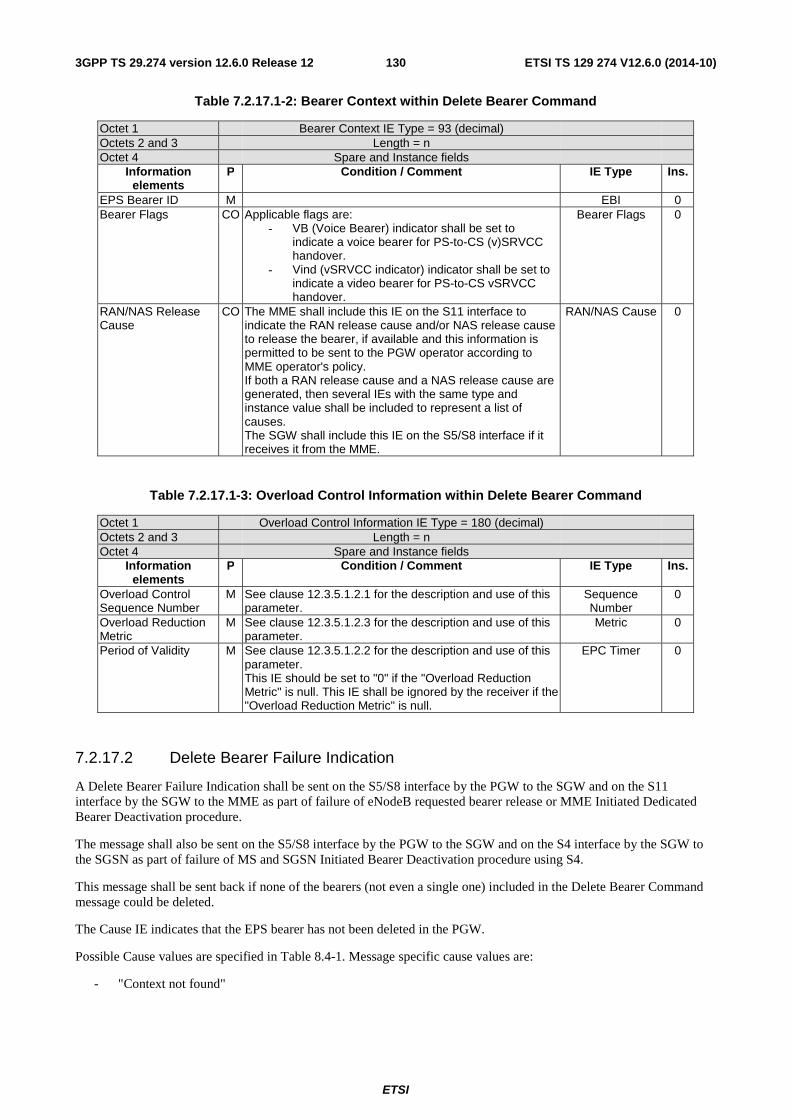
ETSI
ETSI TS 129 274 V12.6.0 (2014-10)1303GPP TS 29.274 version 12.6.0 Release 12
Table 7.2.17.1-2: Bearer Context within Delete Bearer Command
Octet 1 Bearer Context IE Type = 93 (decimal) Octets 2 and 3 Length = n Octet 4 Spare and Instance fields
Information elements
P Condition / Comment IE Type Ins.
EPS Bearer ID M EBI 0 Bearer Flags CO Applicable flags are:
- VB (Voice Bearer) indicator shall be set to indicate a voice bearer for PS-to-CS (v)SRVCC handover.
- Vind (vSRVCC indicator) indicator shall be set to indicate a video bearer for PS-to-CS vSRVCC handover.
Bearer Flags 0
RAN/NAS Release Cause
CO
The MME shall include this IE on the S11 interface to indicate the RAN release cause and/or NAS release cause to release the bearer, if available and this information is permitted to be sent to the PGW operator according to MME operator's policy. If both a RAN release cause and a NAS release cause are generated, then several IEs with the same type and instance value shall be included to represent a list of causes. The SGW shall include this IE on the S5/S8 interface if it receives it from the MME.
RAN/NAS Cause 0
Table 7.2.17.1-3: Overload Control Information within Delete Bearer Command
Octet 1 Overload Control Information IE Type = 180 (decimal) Octets 2 and 3 Length = n Octet 4 Spare and Instance fields
Information elements
P Condition / Comment IE Type Ins.
Overload Control Sequence Number
M See clause 12.3.5.1.2.1 for the description and use of this parameter.
Sequence Number
0
Overload Reduction Metric
M See clause 12.3.5.1.2.3 for the description and use of this parameter.
Metric 0
Period of Validity M See clause 12.3.5.1.2.2 for the description and use of this parameter. This IE should be set to "0" if the "Overload Reduction Metric" is null. This IE shall be ignored by the receiver if the "Overload Reduction Metric" is null.
EPC Timer 0
7.2.17.2 Delete Bearer Failure Indication
A Delete Bearer Failure Indication shall be sent on the S5/S8 interface by the PGW to the SGW and on the S11 interface by the SGW to the MME as part of failure of eNodeB requested bearer release or MME Initiated Dedicated Bearer Deactivation procedure.
The message shall also be sent on the S5/S8 interface by the PGW to the SGW and on the S4 interface by the SGW to the SGSN as part of failure of MS and SGSN Initiated Bearer Deactivation procedure using S4.
This message shall be sent back if none of the bearers (not even a single one) included in the Delete Bearer Command message could be deleted.
The Cause IE indicates that the EPS bearer has not been deleted in the PGW.
Possible Cause values are specified in Table 8.4-1. Message specific cause values are:
- "Context not found"
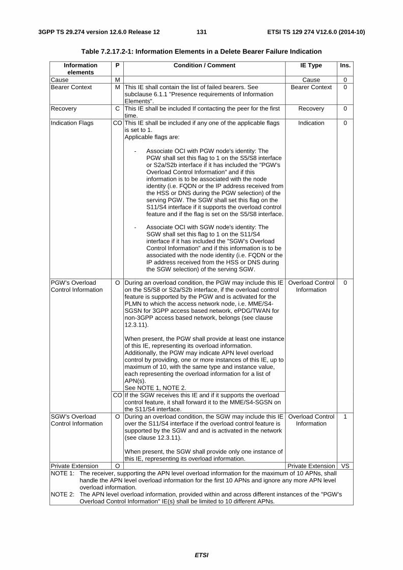
ETSI
ETSI TS 129 274 V12.6.0 (2014-10)1313GPP TS 29.274 version 12.6.0 Release 12
Table 7.2.17.2-1: Information Elements in a Delete Bearer Failure Indication
Information elements
P Condition / Comment IE Type Ins.
Cause M Cause 0 Bearer Context M This IE shall contain the list of failed bearers. See
subclause 6.1.1 "Presence requirements of Information Elements".
Bearer Context 0
Recovery C This IE shall be included If contacting the peer for the first time.
Recovery 0
Indication Flags CO This IE shall be included if any one of the applicable flags is set to 1. Applicable flags are:
- Associate OCI with PGW node's identity: The PGW shall set this flag to 1 on the S5/S8 interface or S2a/S2b interface if it has included the "PGW's Overload Control Information" and if this information is to be associated with the node identity (i.e. FQDN or the IP address received from the HSS or DNS during the PGW selection) of the serving PGW. The SGW shall set this flag on the S11/S4 interface if it supports the overload control feature and if the flag is set on the S5/S8 interface.
- Associate OCI with SGW node's identity: The SGW shall set this flag to 1 on the S11/S4 interface if it has included the "SGW's Overload Control Information" and if this information is to be associated with the node identity (i.e. FQDN or the IP address received from the HSS or DNS during the SGW selection) of the serving SGW.
Indication 0
PGW's Overload Control Information
O During an overload condition, the PGW may include this IE on the S5/S8 or S2a/S2b interface, if the overload control feature is supported by the PGW and is activated for the PLMN to which the access network node, i.e. MME/S4-SGSN for 3GPP access based network, ePDG/TWAN for non-3GPP access based network, belongs (see clause 12.3.11). When present, the PGW shall provide at least one instance of this IE, representing its overload information. Additionally, the PGW may indicate APN level overload control by providing, one or more instances of this IE, up to maximum of 10, with the same type and instance value, each representing the overload information for a list of APN(s). See NOTE 1, NOTE 2.
Overload Control Information
0
CO If the SGW receives this IE and if it supports the overload control feature, it shall forward it to the MME/S4-SGSN on the S11/S4 interface.
SGW's Overload Control Information
O During an overload condition, the SGW may include this IE over the S11/S4 interface if the overload control feature is supported by the SGW and and is activated in the network (see clause 12.3.11). When present, the SGW shall provide only one instance of this IE, representing its overload information.
Overload Control Information
1
Private Extension O Private Extension VS NOTE 1: The receiver, supporting the APN level overload information for the maximum of 10 APNs, shall
handle the APN level overload information for the first 10 APNs and ignore any more APN level overload information.
NOTE 2: The APN level overload information, provided within and across different instances of the "PGW's Overload Control Information" IE(s) shall be limited to 10 different APNs.
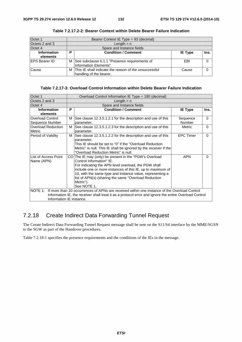
ETSI
ETSI TS 129 274 V12.6.0 (2014-10)1323GPP TS 29.274 version 12.6.0 Release 12
Table 7.2.17.2-2: Bearer Context within Delete Bearer Failure Indication
Octet 1 Bearer Context IE Type = 93 (decimal) Octets 2 and 3 Length = n Octet 4 Spare and Instance fields
Information elements
P Condition / Comment IE Type Ins.
EPS Bearer ID M See subclause 6.1.1 "Presence requirements of Information Elements".
EBI 0
Cause M This IE shall indicate the reason of the unsuccessful handling of the bearer.
Cause 0
Table 7.2.17-3: Overload Control Information within Delete Bearer Failure Indication
Octet 1 Overload Control Information IE Type = 180 (decimal) Octets 2 and 3 Length = n Octet 4 Spare and Instance fields
Information elements
P Condition / Comment IE Type Ins.
Overload Control Sequence Number
M See clause 12.3.5.1.2.1 for the description and use of this parameter.
Sequence Number
0
Overload Reduction Metric
M See clause 12.3.5.1.2.3 for the description and use of this parameter.
Metric 0
Period of Validity M See clause 12.3.5.1.2.2 for the description and use of this parameter. This IE should be set to "0" if the "Overload Reduction Metric" is null. This IE shall be ignored by the receiver if the "Overload Reduction Metric" is null.
EPC Timer 0
List of Access Point Name (APN)
CO The IE may (only) be present in the "PGW's Overload Control Information" IE. For indicating the APN level overload, the PGW shall include one or more instances of this IE, up to maximum of 10, with the same type and instance value, representing a list of APN(s) (sharing the same "Overload Reduction Metric"). See NOTE 1.
APN 0
NOTE 1: If more than 10 occurrences of APNs are received within one instance of the Overload Control Information IE, the receiver shall treat it as a protocol error and ignore the entire Overload Control Information IE instance.
7.2.18 Create Indirect Data Forwarding Tunnel Request
The Create Indirect Data Forwarding Tunnel Request message shall be sent on the S11/S4 interface by the MME/SGSN to the SGW as part of the Handover procedures.
Table 7.2.18-1 specifies the presence requirements and the conditions of the IEs in the message.
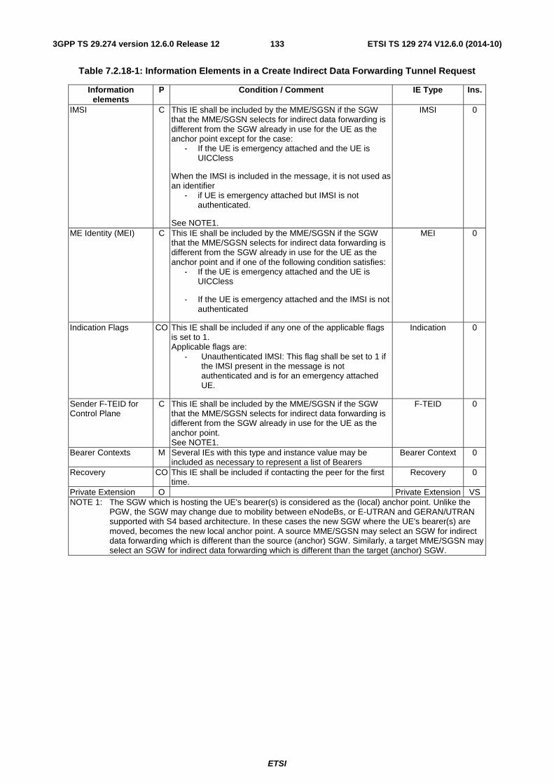
ETSI
ETSI TS 129 274 V12.6.0 (2014-10)1333GPP TS 29.274 version 12.6.0 Release 12
Table 7.2.18-1: Information Elements in a Create Indirect Data Forwarding Tunnel Request
Information elements
P Condition / Comment IE Type Ins.
IMSI C This IE shall be included by the MME/SGSN if the SGW that the MME/SGSN selects for indirect data forwarding is different from the SGW already in use for the UE as the anchor point except for the case:
- If the UE is emergency attached and the UE is UICCless
When the IMSI is included in the message, it is not used as an identifier
- if UE is emergency attached but IMSI is not authenticated.
See NOTE1.
IMSI 0
ME Identity (MEI) C This IE shall be included by the MME/SGSN if the SGW that the MME/SGSN selects for indirect data forwarding is different from the SGW already in use for the UE as the anchor point and if one of the following condition satisfies:
- If the UE is emergency attached and the UE is UICCless
- If the UE is emergency attached and the IMSI is not authenticated
MEI 0
Indication Flags CO This IE shall be included if any one of the applicable flags is set to 1. Applicable flags are:
- Unauthenticated IMSI: This flag shall be set to 1 if the IMSI present in the message is not authenticated and is for an emergency attached UE.
Indication 0
Sender F-TEID for Control Plane
C This IE shall be included by the MME/SGSN if the SGW that the MME/SGSN selects for indirect data forwarding is different from the SGW already in use for the UE as the anchor point. See NOTE1.
F-TEID 0
Bearer Contexts M Several IEs with this type and instance value may be included as necessary to represent a list of Bearers
Bearer Context 0
Recovery CO This IE shall be included if contacting the peer for the first time.
Recovery 0
Private Extension O Private Extension VS NOTE 1: The SGW which is hosting the UE's bearer(s) is considered as the (local) anchor point. Unlike the
PGW, the SGW may change due to mobility between eNodeBs, or E-UTRAN and GERAN/UTRAN supported with S4 based architecture. In these cases the new SGW where the UE's bearer(s) are moved, becomes the new local anchor point. A source MME/SGSN may select an SGW for indirect data forwarding which is different than the source (anchor) SGW. Similarly, a target MME/SGSN may select an SGW for indirect data forwarding which is different than the target (anchor) SGW.
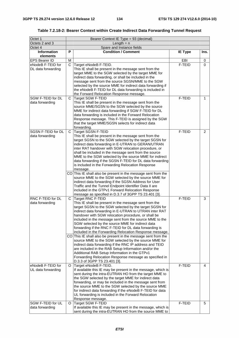
ETSI
ETSI TS 129 274 V12.6.0 (2014-10)1343GPP TS 29.274 version 12.6.0 Release 12
Table 7.2.18-2: Bearer Context within Create Indirect Data Forwarding Tunnel Request
Octet 1 Bearer Context IE Type = 93 (decimal) Octets 2 and 3 Length = n Octet 4 Spare and Instance fields
Information elements
P Condition / Comment IE Type Ins.
EPS Bearer ID M EBI 0 eNodeB F-TEID for DL data forwarding
C Target eNodeB F-TEID. This IE shall be present in the message sent from the target MME to the SGW selected by the target MME for indirect data forwarding, or shall be included in the message sent from the source SGSN/MME to the SGW selected by the source MME for indirect data forwarding if the eNodeB F-TEID for DL data forwarding is included in the Forward Relocation Response message.
F-TEID 0
SGW F-TEID for DL data forwarding
C Target SGW F-TEID This IE shall be present in the message sent from the source MME/SGSN to the SGW selected by the source MME for indirect data forwarding if SGW F-TEID for DL data forwarding is included in the Forward Relocation Response message. This F-TEID is assigned by the SGW that the target MME/SGSN selects for indirect data forwarding.
F-TEID 1
SGSN F-TEID for DL data forwarding
C Target SGSN F-TEID This IE shall be present in the message sent from the target SGSN to the SGW selected by the target SGSN for indirect data forwarding in E-UTRAN to GERAN/UTRAN inter RAT handover with SGW relocation procedure, or shall be included in the message sent from the source MME to the SGW selected by the source MME for indirect data forwarding if the SGSN F-TEID for DL data forwarding is included in the Forwarding Relocation Response message.
F-TEID 2
CO This IE shall also be present in the message sent from the source MME to the SGW selected by the source MME for indirect data forwarding if the SGSN Address for User Traffic and the Tunnel Endpoint Identifier Data II are included in the GTPv1 Forward Relocation Response message as specified in D.3.7 of 3GPP TS 23.401 [3].
RNC F-TEID for DL data forwarding
C Target RNC F-TEID This IE shall be present in the message sent from the target SGSN to the SGW selected by the target SGSN for indirect data forwarding in E-UTRAN to UTRAN inter RAT handover with SGW relocation procedure, or shall be included in the message sent from the source MME to the SGW selected by the source MME for indirect data forwarding if the RNC F-TEID for DL data forwarding is included in the Forwarding Relocation Response message.
F-TEID 3
CO This IE shall also be present in the message sent from the source MME to the SGW selected by the source MME for indirect data forwarding if the RNC IP address and TEID are included in the RAB Setup Information and/or the Additional RAB Setup Information in the GTPv1 Forwarding Relocation Response message as specified in D.3.3 of 3GPP TS 23.401 [3].
eNodeB F-TEID for UL data forwarding
O Target eNodeB F-TEID. If available this IE may be present in the message, which is sent during the intra-EUTRAN HO from the target MME to the SGW selected by the target MME for indirect data forwarding, or may be included in the message sent from the source MME to the SGW selected by the source MME for indirect data forwarding if the eNodeB F-TEID for data UL forwarding is included in the Forward Relocation Response message.
F-TEID 4
SGW F-TEID for UL data forwarding
O Target SGW F-TEID If available this IE may be present in the message, which is sent during the intra-EUTRAN HO from the source MME to
F-TEID 5
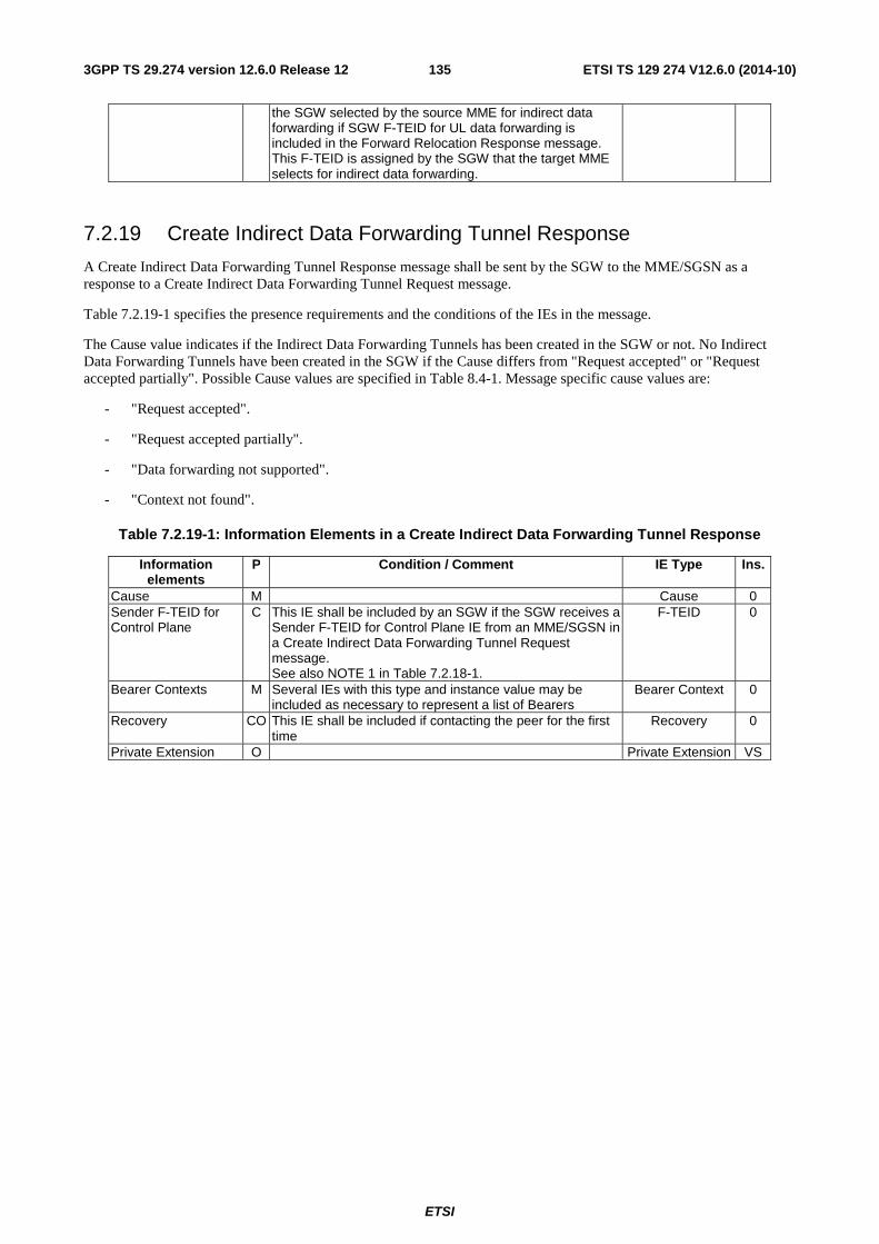
ETSI
ETSI TS 129 274 V12.6.0 (2014-10)1353GPP TS 29.274 version 12.6.0 Release 12
the SGW selected by the source MME for indirect data forwarding if SGW F-TEID for UL data forwarding is included in the Forward Relocation Response message. This F-TEID is assigned by the SGW that the target MME selects for indirect data forwarding.
7.2.19 Create Indirect Data Forwarding Tunnel Response
A Create Indirect Data Forwarding Tunnel Response message shall be sent by the SGW to the MME/SGSN as a response to a Create Indirect Data Forwarding Tunnel Request message.
Table 7.2.19-1 specifies the presence requirements and the conditions of the IEs in the message.
The Cause value indicates if the Indirect Data Forwarding Tunnels has been created in the SGW or not. No Indirect Data Forwarding Tunnels have been created in the SGW if the Cause differs from "Request accepted" or "Request accepted partially". Possible Cause values are specified in Table 8.4-1. Message specific cause values are:
- "Request accepted".
- "Request accepted partially".
- "Data forwarding not supported".
- "Context not found".
Table 7.2.19-1: Information Elements in a Create Indirect Data Forwarding Tunnel Response
Information elements
P Condition / Comment IE Type Ins.
Cause M Cause 0 Sender F-TEID for Control Plane
C This IE shall be included by an SGW if the SGW receives a Sender F-TEID for Control Plane IE from an MME/SGSN in a Create Indirect Data Forwarding Tunnel Request message. See also NOTE 1 in Table 7.2.18-1.
F-TEID 0
Bearer Contexts M Several IEs with this type and instance value may be included as necessary to represent a list of Bearers
Bearer Context 0
Recovery CO This IE shall be included if contacting the peer for the first time
Recovery 0
Private Extension O Private Extension VS
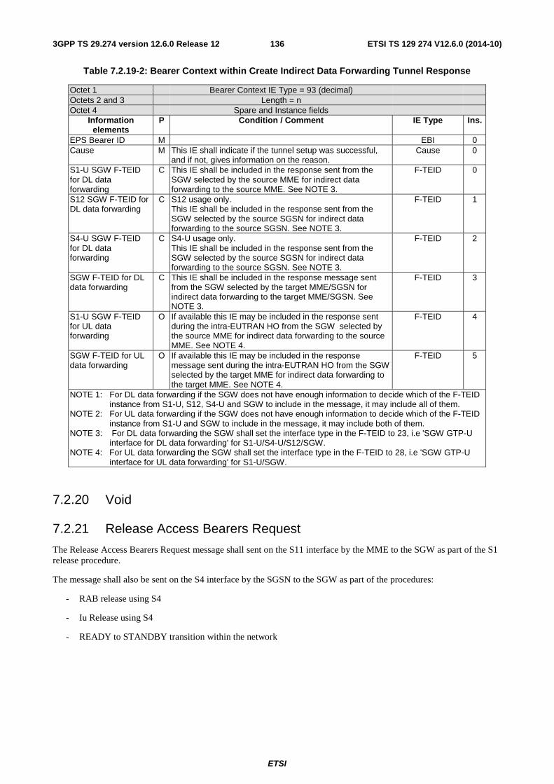
ETSI
ETSI TS 129 274 V12.6.0 (2014-10)1363GPP TS 29.274 version 12.6.0 Release 12
Table 7.2.19-2: Bearer Context within Create Indirect Data Forwarding Tunnel Response
Octet 1 Bearer Context IE Type = 93 (decimal) Octets 2 and 3 Length = n Octet 4 Spare and Instance fields
Information elements
P Condition / Comment IE Type Ins.
EPS Bearer ID M EBI 0 Cause M This IE shall indicate if the tunnel setup was successful,
and if not, gives information on the reason. Cause 0
S1-U SGW F-TEID for DL data forwarding
C This IE shall be included in the response sent from the SGW selected by the source MME for indirect data forwarding to the source MME. See NOTE 3.
F-TEID 0
S12 SGW F-TEID for DL data forwarding
C S12 usage only. This IE shall be included in the response sent from the SGW selected by the source SGSN for indirect data forwarding to the source SGSN. See NOTE 3.
F-TEID 1
S4-U SGW F-TEID for DL data forwarding
C S4-U usage only. This IE shall be included in the response sent from the SGW selected by the source SGSN for indirect data forwarding to the source SGSN. See NOTE 3.
F-TEID 2
SGW F-TEID for DL data forwarding
C This IE shall be included in the response message sent from the SGW selected by the target MME/SGSN for indirect data forwarding to the target MME/SGSN. See NOTE 3.
F-TEID 3
S1-U SGW F-TEID for UL data forwarding
O If available this IE may be included in the response sent during the intra-EUTRAN HO from the SGW selected by the source MME for indirect data forwarding to the source MME. See NOTE 4.
F-TEID 4
SGW F-TEID for UL data forwarding
O If available this IE may be included in the response message sent during the intra-EUTRAN HO from the SGW selected by the target MME for indirect data forwarding to the target MME. See NOTE 4.
F-TEID 5
NOTE 1: For DL data forwarding if the SGW does not have enough information to decide which of the F-TEID instance from S1-U, S12, S4-U and SGW to include in the message, it may include all of them.
NOTE 2: For UL data forwarding if the SGW does not have enough information to decide which of the F-TEID instance from S1-U and SGW to include in the message, it may include both of them.
NOTE 3: For DL data forwarding the SGW shall set the interface type in the F-TEID to 23, i.e 'SGW GTP-U interface for DL data forwarding' for S1-U/S4-U/S12/SGW.
NOTE 4: For UL data forwarding the SGW shall set the interface type in the F-TEID to 28, i.e 'SGW GTP-U interface for UL data forwarding' for S1-U/SGW.
7.2.20 Void
7.2.21 Release Access Bearers Request
The Release Access Bearers Request message shall sent on the S11 interface by the MME to the SGW as part of the S1 release procedure.
The message shall also be sent on the S4 interface by the SGSN to the SGW as part of the procedures:
- RAB release using S4
- Iu Release using S4
- READY to STANDBY transition within the network
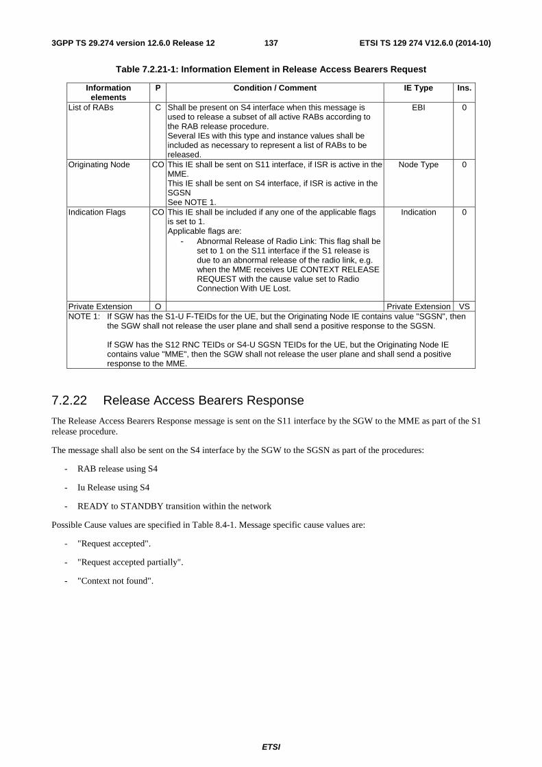
ETSI
ETSI TS 129 274 V12.6.0 (2014-10)1373GPP TS 29.274 version 12.6.0 Release 12
Table 7.2.21-1: Information Element in Release Access Bearers Request
Information elements
P Condition / Comment IE Type Ins.
List of RABs C Shall be present on S4 interface when this message is used to release a subset of all active RABs according to the RAB release procedure. Several IEs with this type and instance values shall be included as necessary to represent a list of RABs to be released.
EBI 0
Originating Node CO This IE shall be sent on S11 interface, if ISR is active in the MME. This IE shall be sent on S4 interface, if ISR is active in the SGSN See NOTE 1.
Node Type 0
Indication Flags CO This IE shall be included if any one of the applicable flags is set to 1. Applicable flags are:
- Abnormal Release of Radio Link: This flag shall be set to 1 on the S11 interface if the S1 release is due to an abnormal release of the radio link, e.g. when the MME receives UE CONTEXT RELEASE REQUEST with the cause value set to Radio Connection With UE Lost.
Indication 0
Private Extension O Private Extension VS NOTE 1: If SGW has the S1-U F-TEIDs for the UE, but the Originating Node IE contains value "SGSN", then
the SGW shall not release the user plane and shall send a positive response to the SGSN. If SGW has the S12 RNC TEIDs or S4-U SGSN TEIDs for the UE, but the Originating Node IE contains value "MME", then the SGW shall not release the user plane and shall send a positive response to the MME.
7.2.22 Release Access Bearers Response
The Release Access Bearers Response message is sent on the S11 interface by the SGW to the MME as part of the S1 release procedure.
The message shall also be sent on the S4 interface by the SGW to the SGSN as part of the procedures:
- RAB release using S4
- Iu Release using S4
- READY to STANDBY transition within the network
Possible Cause values are specified in Table 8.4-1. Message specific cause values are:
- "Request accepted".
- "Request accepted partially".
- "Context not found".
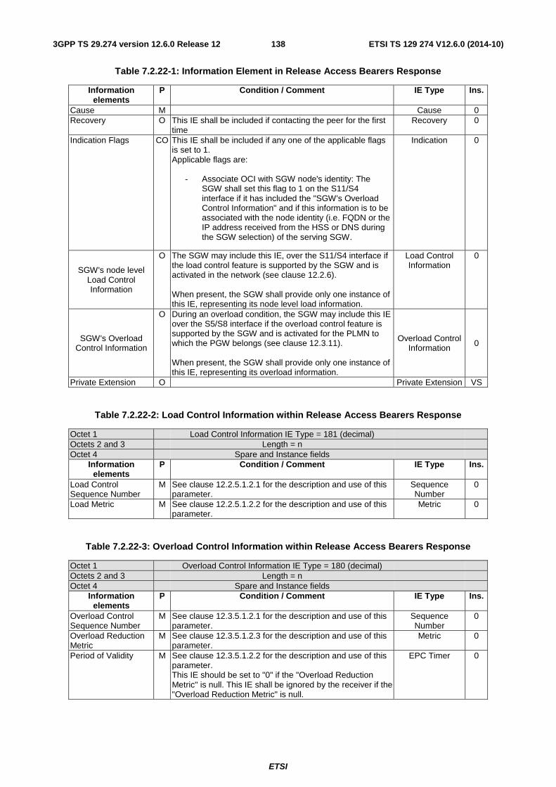
ETSI
ETSI TS 129 274 V12.6.0 (2014-10)1383GPP TS 29.274 version 12.6.0 Release 12
Table 7.2.22-1: Information Element in Release Access Bearers Response
Information elements
P Condition / Comment IE Type Ins.
Cause M Cause 0 Recovery O This IE shall be included if contacting the peer for the first
time Recovery 0
Indication Flags CO This IE shall be included if any one of the applicable flags is set to 1. Applicable flags are:
- Associate OCI with SGW node's identity: The SGW shall set this flag to 1 on the S11/S4 interface if it has included the "SGW's Overload Control Information" and if this information is to be associated with the node identity (i.e. FQDN or the IP address received from the HSS or DNS during the SGW selection) of the serving SGW.
Indication 0
SGW's node level Load Control Information
O The SGW may include this IE, over the S11/S4 interface if the load control feature is supported by the SGW and is activated in the network (see clause 12.2.6). When present, the SGW shall provide only one instance of this IE, representing its node level load information.
Load Control Information
0
SGW's Overload Control Information
O During an overload condition, the SGW may include this IE over the S5/S8 interface if the overload control feature is supported by the SGW and is activated for the PLMN to which the PGW belongs (see clause 12.3.11). When present, the SGW shall provide only one instance of this IE, representing its overload information.
Overload Control Information 0
Private Extension O Private Extension VS
Table 7.2.22-2: Load Control Information within Release Access Bearers Response
Octet 1 Load Control Information IE Type = 181 (decimal) Octets 2 and 3 Length = n Octet 4 Spare and Instance fields
Information elements
P Condition / Comment IE Type Ins.
Load Control Sequence Number
M See clause 12.2.5.1.2.1 for the description and use of this parameter.
Sequence Number
0
Load Metric M See clause 12.2.5.1.2.2 for the description and use of this parameter.
Metric 0
Table 7.2.22-3: Overload Control Information within Release Access Bearers Response
Octet 1 Overload Control Information IE Type = 180 (decimal) Octets 2 and 3 Length = n Octet 4 Spare and Instance fields
Information elements
P Condition / Comment IE Type Ins.
Overload Control Sequence Number
M See clause 12.3.5.1.2.1 for the description and use of this parameter.
Sequence Number
0
Overload Reduction Metric
M See clause 12.3.5.1.2.3 for the description and use of this parameter.
Metric 0
Period of Validity M See clause 12.3.5.1.2.2 for the description and use of this parameter. This IE should be set to "0" if the "Overload Reduction Metric" is null. This IE shall be ignored by the receiver if the "Overload Reduction Metric" is null.
EPC Timer 0
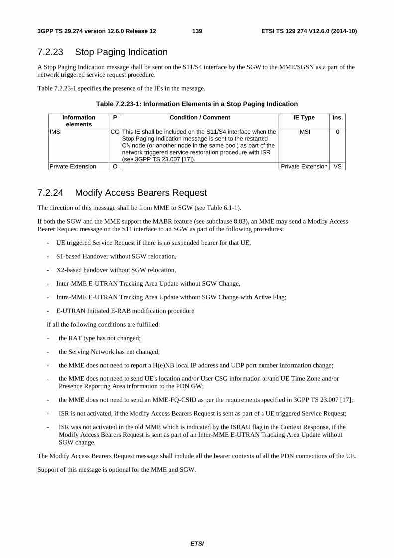
ETSI
ETSI TS 129 274 V12.6.0 (2014-10)1393GPP TS 29.274 version 12.6.0 Release 12
7.2.23 Stop Paging Indication
A Stop Paging Indication message shall be sent on the S11/S4 interface by the SGW to the MME/SGSN as a part of the network triggered service request procedure.
Table 7.2.23-1 specifies the presence of the IEs in the message.
Table 7.2.23-1: Information Elements in a Stop Paging Indication
Information elements
P Condition / Comment IE Type Ins.
IMSI CO This IE shall be included on the S11/S4 interface when the Stop Paging Indication message is sent to the restarted CN node (or another node in the same pool) as part of the network triggered service restoration procedure with ISR (see 3GPP TS 23.007 [17]).
IMSI 0
Private Extension O Private Extension VS
7.2.24 Modify Access Bearers Request
The direction of this message shall be from MME to SGW (see Table 6.1-1).
If both the SGW and the MME support the MABR feature (see subclause 8.83), an MME may send a Modify Access Bearer Request message on the S11 interface to an SGW as part of the following procedures:
- UE triggered Service Request if there is no suspended bearer for that UE,
- S1-based Handover without SGW relocation,
- X2-based handover without SGW relocation,
- Inter-MME E-UTRAN Tracking Area Update without SGW Change,
- Intra-MME E-UTRAN Tracking Area Update without SGW Change with Active Flag;
- E-UTRAN Initiated E-RAB modification procedure
if all the following conditions are fulfilled:
- the RAT type has not changed;
- the Serving Network has not changed;
- the MME does not need to report a H(e)NB local IP address and UDP port number information change;
- the MME does not need to send UE's location and/or User CSG information or/and UE Time Zone and/or Presence Reporting Area information to the PDN GW;
- the MME does not need to send an MME-FQ-CSID as per the requirements specified in 3GPP TS 23.007 [17];
- ISR is not activated, if the Modify Access Bearers Request is sent as part of a UE triggered Service Request;
- ISR was not activated in the old MME which is indicated by the ISRAU flag in the Context Response, if the Modify Access Bearers Request is sent as part of an Inter-MME E-UTRAN Tracking Area Update without SGW change.
The Modify Access Bearers Request message shall include all the bearer contexts of all the PDN connections of the UE.
Support of this message is optional for the MME and SGW.
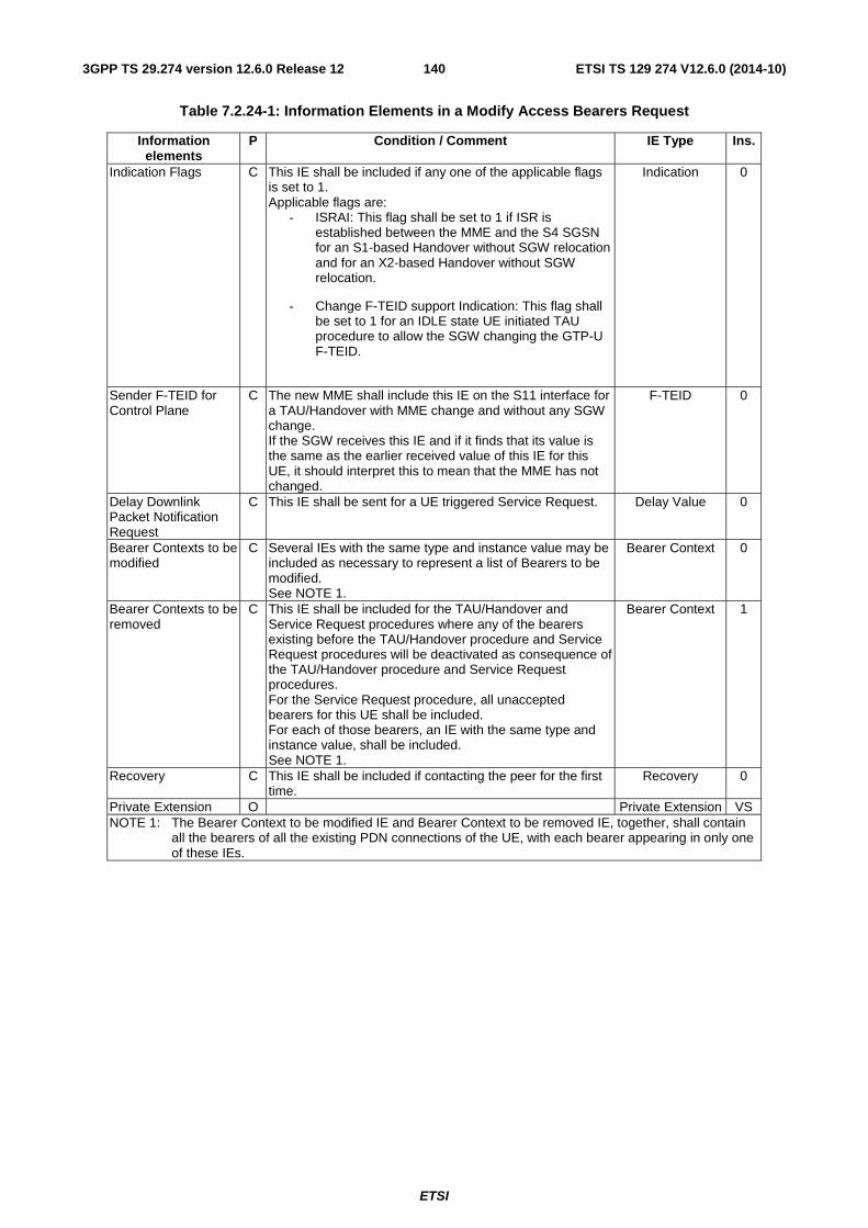
ETSI
ETSI TS 129 274 V12.6.0 (2014-10)1403GPP TS 29.274 version 12.6.0 Release 12
Table 7.2.24-1: Information Elements in a Modify Access Bearers Request
Information elements
P Condition / Comment IE Type Ins.
Indication Flags C This IE shall be included if any one of the applicable flags is set to 1. Applicable flags are:
- ISRAI: This flag shall be set to 1 if ISR is established between the MME and the S4 SGSN for an S1-based Handover without SGW relocation and for an X2-based Handover without SGW relocation.
- Change F-TEID support Indication: This flag shall be set to 1 for an IDLE state UE initiated TAU procedure to allow the SGW changing the GTP-U F-TEID.
Indication 0
Sender F-TEID for Control Plane
C The new MME shall include this IE on the S11 interface for a TAU/Handover with MME change and without any SGW change. If the SGW receives this IE and if it finds that its value is the same as the earlier received value of this IE for this UE, it should interpret this to mean that the MME has not changed.
F-TEID 0
Delay Downlink Packet Notification Request
C This IE shall be sent for a UE triggered Service Request. Delay Value 0
Bearer Contexts to be modified
C Several IEs with the same type and instance value may be included as necessary to represent a list of Bearers to be modified. See NOTE 1.
Bearer Context 0
Bearer Contexts to be removed
C This IE shall be included for the TAU/Handover and Service Request procedures where any of the bearers existing before the TAU/Handover procedure and Service Request procedures will be deactivated as consequence of the TAU/Handover procedure and Service Request procedures. For the Service Request procedure, all unaccepted bearers for this UE shall be included. For each of those bearers, an IE with the same type and instance value, shall be included. See NOTE 1.
Bearer Context 1
Recovery C This IE shall be included if contacting the peer for the first time.
Recovery 0
Private Extension O Private Extension VS NOTE 1: The Bearer Context to be modified IE and Bearer Context to be removed IE, together, shall contain
all the bearers of all the existing PDN connections of the UE, with each bearer appearing in only one of these IEs.
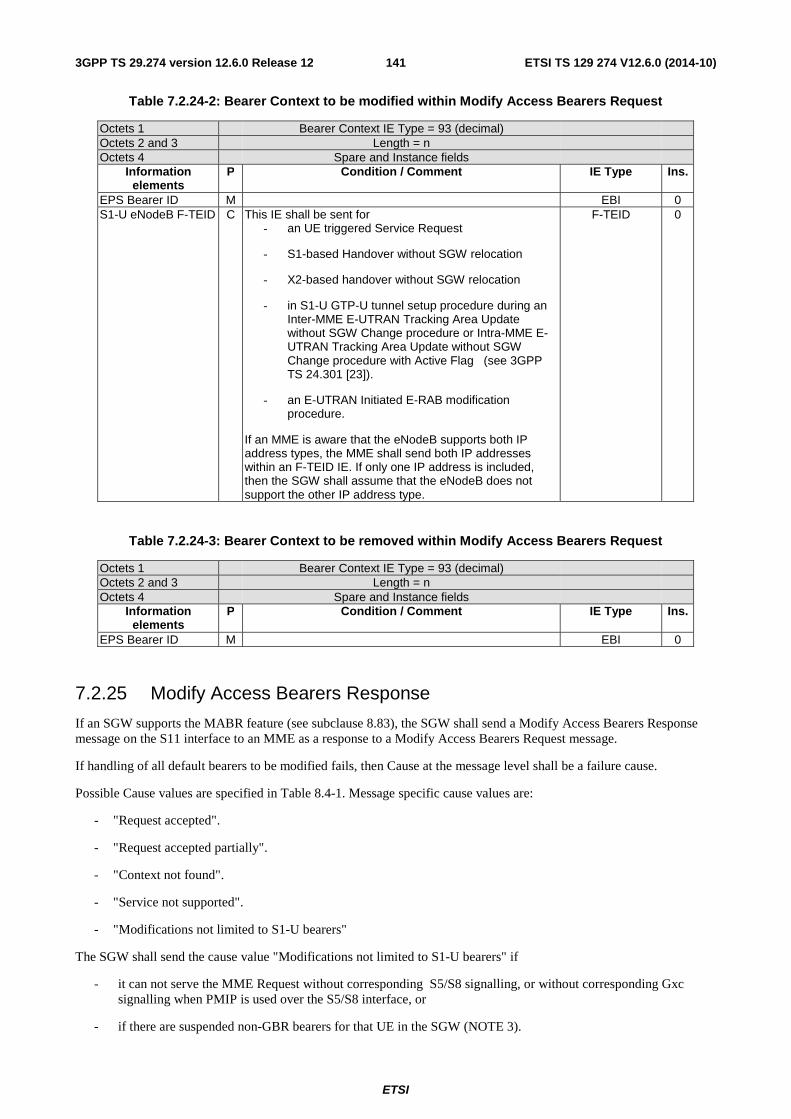
ETSI
ETSI TS 129 274 V12.6.0 (2014-10)1413GPP TS 29.274 version 12.6.0 Release 12
Table 7.2.24-2: Bearer Context to be modified within Modify Access Bearers Request
Octets 1 Bearer Context IE Type = 93 (decimal) Octets 2 and 3 Length = n Octets 4 Spare and Instance fields
Information elements
P Condition / Comment IE Type Ins.
EPS Bearer ID M EBI 0 S1-U eNodeB F-TEID C This IE shall be sent for
- an UE triggered Service Request
- S1-based Handover without SGW relocation
- X2-based handover without SGW relocation
- in S1-U GTP-U tunnel setup procedure during an Inter-MME E-UTRAN Tracking Area Update without SGW Change procedure or Intra-MME E-UTRAN Tracking Area Update without SGW Change procedure with Active Flag (see 3GPP TS 24.301 [23]).
- an E-UTRAN Initiated E-RAB modification procedure.
If an MME is aware that the eNodeB supports both IP address types, the MME shall send both IP addresses within an F-TEID IE. If only one IP address is included, then the SGW shall assume that the eNodeB does not support the other IP address type.
F-TEID 0
Table 7.2.24-3: Bearer Context to be removed within Modify Access Bearers Request
Octets 1 Bearer Context IE Type = 93 (decimal) Octets 2 and 3 Length = n Octets 4 Spare and Instance fields
Information elements
P Condition / Comment IE Type Ins.
EPS Bearer ID M EBI 0
7.2.25 Modify Access Bearers Response
If an SGW supports the MABR feature (see subclause 8.83), the SGW shall send a Modify Access Bearers Response message on the S11 interface to an MME as a response to a Modify Access Bearers Request message.
If handling of all default bearers to be modified fails, then Cause at the message level shall be a failure cause.
Possible Cause values are specified in Table 8.4-1. Message specific cause values are:
- "Request accepted".
- "Request accepted partially".
- "Context not found".
- "Service not supported".
- "Modifications not limited to S1-U bearers"
The SGW shall send the cause value "Modifications not limited to S1-U bearers" if
- it can not serve the MME Request without corresponding S5/S8 signalling, or without corresponding Gxc signalling when PMIP is used over the S5/S8 interface, or
- if there are suspended non-GBR bearers for that UE in the SGW (NOTE 3).
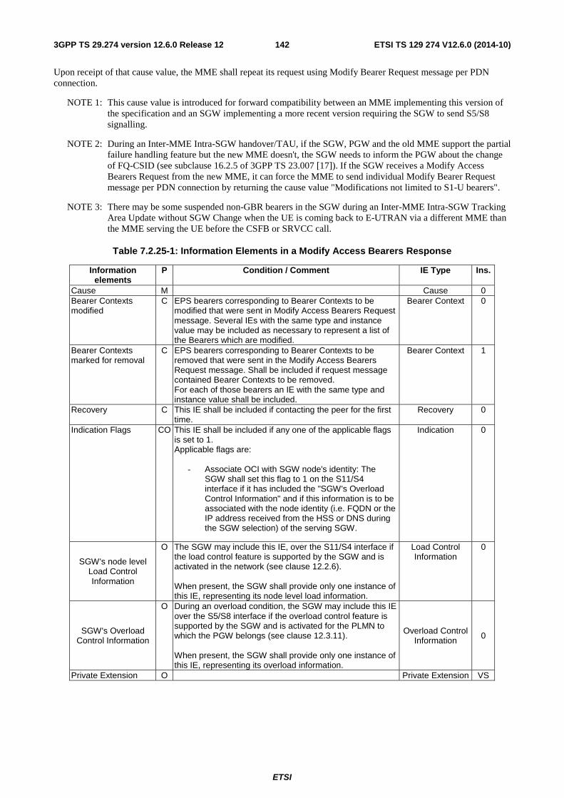
ETSI
ETSI TS 129 274 V12.6.0 (2014-10)1423GPP TS 29.274 version 12.6.0 Release 12
Upon receipt of that cause value, the MME shall repeat its request using Modify Bearer Request message per PDN connection.
NOTE 1: This cause value is introduced for forward compatibility between an MME implementing this version of the specification and an SGW implementing a more recent version requiring the SGW to send S5/S8 signalling.
NOTE 2: During an Inter-MME Intra-SGW handover/TAU, if the SGW, PGW and the old MME support the partial failure handling feature but the new MME doesn't, the SGW needs to inform the PGW about the change of FQ-CSID (see subclause 16.2.5 of 3GPP TS 23.007 [17]). If the SGW receives a Modify Access Bearers Request from the new MME, it can force the MME to send individual Modify Bearer Request message per PDN connection by returning the cause value "Modifications not limited to S1-U bearers".
NOTE 3: There may be some suspended non-GBR bearers in the SGW during an Inter-MME Intra-SGW Tracking Area Update without SGW Change when the UE is coming back to E-UTRAN via a different MME than the MME serving the UE before the CSFB or SRVCC call.
Table 7.2.25-1: Information Elements in a Modify Access Bearers Response
Information elements
P Condition / Comment IE Type Ins.
Cause M Cause 0 Bearer Contexts modified
C EPS bearers corresponding to Bearer Contexts to be modified that were sent in Modify Access Bearers Request message. Several IEs with the same type and instance value may be included as necessary to represent a list of the Bearers which are modified.
Bearer Context 0
Bearer Contexts marked for removal
C EPS bearers corresponding to Bearer Contexts to be removed that were sent in the Modify Access Bearers Request message. Shall be included if request message contained Bearer Contexts to be removed. For each of those bearers an IE with the same type and instance value shall be included.
Bearer Context 1
Recovery C This IE shall be included if contacting the peer for the first time.
Recovery 0
Indication Flags CO This IE shall be included if any one of the applicable flags is set to 1. Applicable flags are:
- Associate OCI with SGW node's identity: The SGW shall set this flag to 1 on the S11/S4 interface if it has included the "SGW's Overload Control Information" and if this information is to be associated with the node identity (i.e. FQDN or the IP address received from the HSS or DNS during the SGW selection) of the serving SGW.
Indication 0
SGW's node level Load Control Information
O The SGW may include this IE, over the S11/S4 interface if the load control feature is supported by the SGW and is activated in the network (see clause 12.2.6). When present, the SGW shall provide only one instance of this IE, representing its node level load information.
Load Control Information
0
SGW's Overload Control Information
O During an overload condition, the SGW may include this IE over the S5/S8 interface if the overload control feature is supported by the SGW and is activated for the PLMN to which the PGW belongs (see clause 12.3.11). When present, the SGW shall provide only one instance of this IE, representing its overload information.
Overload Control Information 0
Private Extension O Private Extension VS
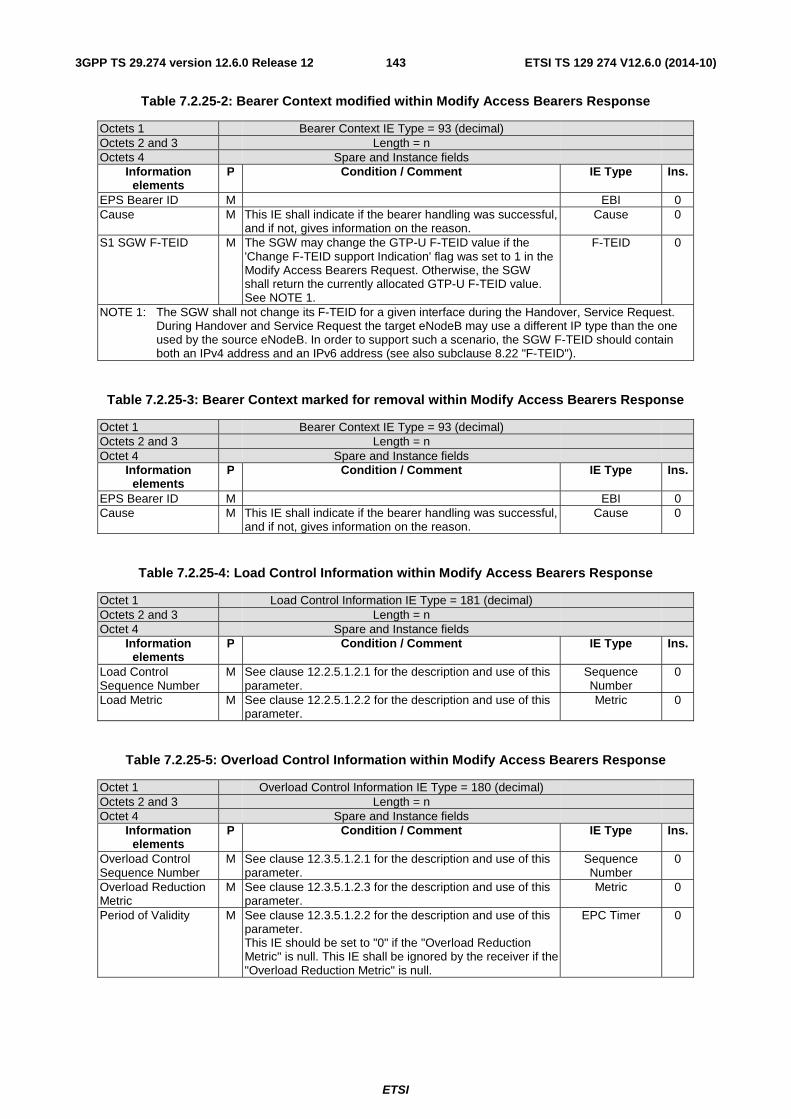
ETSI
ETSI TS 129 274 V12.6.0 (2014-10)1433GPP TS 29.274 version 12.6.0 Release 12
Table 7.2.25-2: Bearer Context modified within Modify Access Bearers Response
Octets 1 Bearer Context IE Type = 93 (decimal) Octets 2 and 3 Length = n Octets 4 Spare and Instance fields
Information elements
P Condition / Comment IE Type Ins.
EPS Bearer ID M EBI 0 Cause M This IE shall indicate if the bearer handling was successful,
and if not, gives information on the reason. Cause 0
S1 SGW F-TEID M The SGW may change the GTP-U F-TEID value if the 'Change F-TEID support Indication' flag was set to 1 in the Modify Access Bearers Request. Otherwise, the SGW shall return the currently allocated GTP-U F-TEID value. See NOTE 1.
F-TEID 0
NOTE 1: The SGW shall not change its F-TEID for a given interface during the Handover, Service Request. During Handover and Service Request the target eNodeB may use a different IP type than the one used by the source eNodeB. In order to support such a scenario, the SGW F-TEID should contain both an IPv4 address and an IPv6 address (see also subclause 8.22 "F-TEID").
Table 7.2.25-3: Bearer Context marked for removal within Modify Access Bearers Response
Octet 1 Bearer Context IE Type = 93 (decimal) Octets 2 and 3 Length = n Octet 4 Spare and Instance fields
Information elements
P Condition / Comment IE Type Ins.
EPS Bearer ID M EBI 0 Cause M This IE shall indicate if the bearer handling was successful,
and if not, gives information on the reason. Cause 0
Table 7.2.25-4: Load Control Information within Modify Access Bearers Response
Octet 1 Load Control Information IE Type = 181 (decimal) Octets 2 and 3 Length = n Octet 4 Spare and Instance fields
Information elements
P Condition / Comment IE Type Ins.
Load Control Sequence Number
M See clause 12.2.5.1.2.1 for the description and use of this parameter.
Sequence Number
0
Load Metric M See clause 12.2.5.1.2.2 for the description and use of this parameter.
Metric 0
Table 7.2.25-5: Overload Control Information within Modify Access Bearers Response
Octet 1 Overload Control Information IE Type = 180 (decimal) Octets 2 and 3 Length = n Octet 4 Spare and Instance fields
Information elements
P Condition / Comment IE Type Ins.
Overload Control Sequence Number
M See clause 12.3.5.1.2.1 for the description and use of this parameter.
Sequence Number
0
Overload Reduction Metric
M See clause 12.3.5.1.2.3 for the description and use of this parameter.
Metric 0
Period of Validity M See clause 12.3.5.1.2.2 for the description and use of this parameter. This IE should be set to "0" if the "Overload Reduction Metric" is null. This IE shall be ignored by the receiver if the "Overload Reduction Metric" is null.
EPC Timer 0
ETSI
ETSI TS 129 274 V12.6.0 (2014-10)1443GPP TS 29.274 version 12.6.0 Release 12
7.3 Mobility Management Messages
7.3.1 Forward Relocation Request
A Forward Relocation Request message shall be sent from the source MME to the target MME over S10 interface as part of S1-based handover relocation procedure from the source MME to the target SGSN, or from the source SGSN to the target MME over S3 interface as part of Inter RAT handover and combined hard handover and SRNS relocation procedures, or from source SGSN to the target SGSN over S16 interface as part of SRNS Relocation and PS handover procedures.
A Forward Relocation Request message shall also be sent from the source MME to the target SGSN over S3 interface as part of SRVCC from E-UTRAN to UTRAN or GERAN with DTM HO support procedures and from source SGSN to the target SGSN over S16 interface as part of SRVCC from UTRAN (HSPA) to UTRAN or GERAN with DTM HO support.
Forward Relocation procedure across S10 interface (when KASME is taken into use) shall be performed according to the Rules on Concurrent Running of Security Procedures, which are specified in 3GPP TS 33.401 [12].
Table 7.3.1-1 specifies the presence requirements and conditions of the IEs in the message.
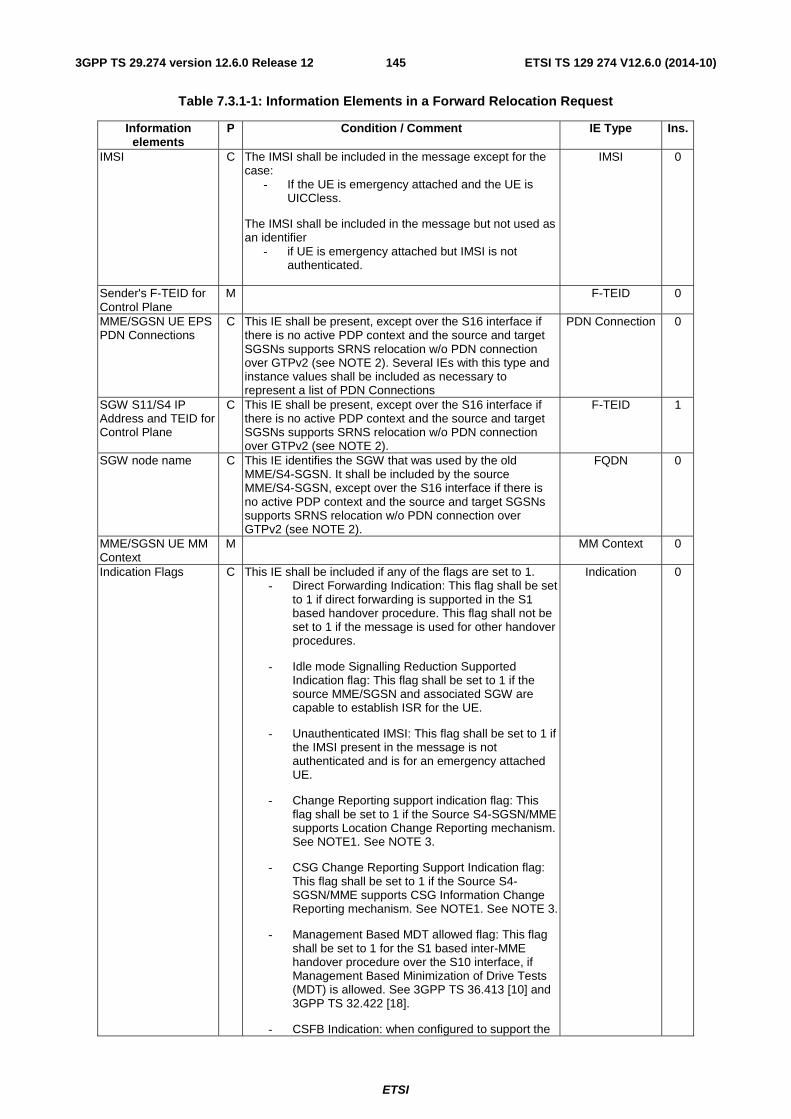
ETSI
ETSI TS 129 274 V12.6.0 (2014-10)1453GPP TS 29.274 version 12.6.0 Release 12
Table 7.3.1-1: Information Elements in a Forward Relocation Request
Information elements
P Condition / Comment IE Type Ins.
IMSI C The IMSI shall be included in the message except for the case:
- If the UE is emergency attached and the UE is UICCless.
The IMSI shall be included in the message but not used as an identifier
- if UE is emergency attached but IMSI is not authenticated.
IMSI 0
Sender's F-TEID for Control Plane
M F-TEID 0
MME/SGSN UE EPS PDN Connections
C This IE shall be present, except over the S16 interface if there is no active PDP context and the source and target SGSNs supports SRNS relocation w/o PDN connection over GTPv2 (see NOTE 2). Several IEs with this type and instance values shall be included as necessary to represent a list of PDN Connections
PDN Connection 0
SGW S11/S4 IP Address and TEID for Control Plane
C This IE shall be present, except over the S16 interface if there is no active PDP context and the source and target SGSNs supports SRNS relocation w/o PDN connection over GTPv2 (see NOTE 2).
F-TEID 1
SGW node name C This IE identifies the SGW that was used by the old MME/S4-SGSN. It shall be included by the source MME/S4-SGSN, except over the S16 interface if there is no active PDP context and the source and target SGSNs supports SRNS relocation w/o PDN connection over GTPv2 (see NOTE 2).
FQDN 0
MME/SGSN UE MM Context
M MM Context 0
Indication Flags C This IE shall be included if any of the flags are set to 1. - Direct Forwarding Indication: This flag shall be set
to 1 if direct forwarding is supported in the S1 based handover procedure. This flag shall not be set to 1 if the message is used for other handover procedures.
- Idle mode Signalling Reduction Supported Indication flag: This flag shall be set to 1 if the source MME/SGSN and associated SGW are capable to establish ISR for the UE.
- Unauthenticated IMSI: This flag shall be set to 1 if the IMSI present in the message is not authenticated and is for an emergency attached UE.
- Change Reporting support indication flag: This flag shall be set to 1 if the Source S4-SGSN/MME supports Location Change Reporting mechanism. See NOTE1. See NOTE 3.
- CSG Change Reporting Support Indication flag: This flag shall be set to 1 if the Source S4-SGSN/MME supports CSG Information Change Reporting mechanism. See NOTE1. See NOTE 3.
- Management Based MDT allowed flag: This flag shall be set to 1 for the S1 based inter-MME handover procedure over the S10 interface, if Management Based Minimization of Drive Tests (MDT) is allowed. See 3GPP TS 36.413 [10] and 3GPP TS 32.422 [18].
- CSFB Indication: when configured to support the
Indication 0
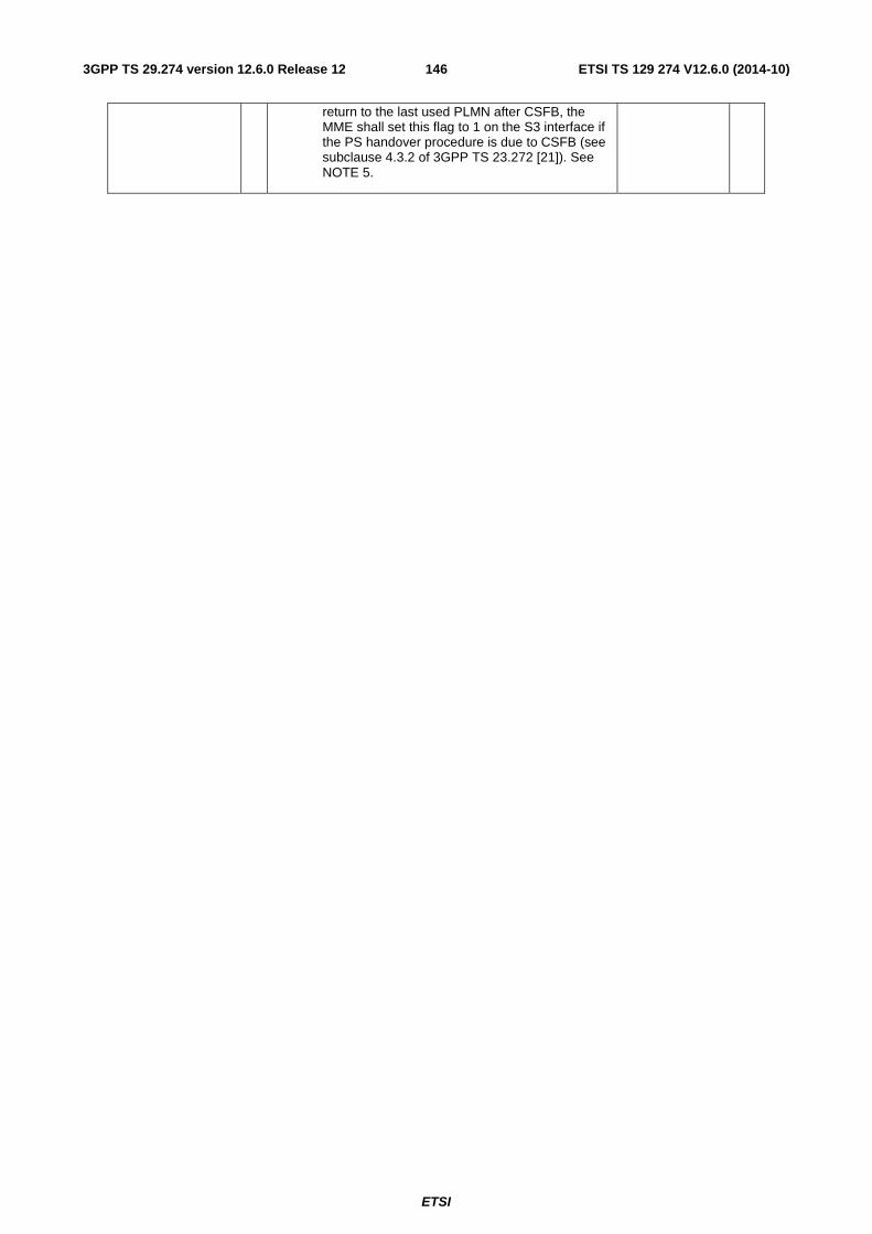
ETSI
ETSI TS 129 274 V12.6.0 (2014-10)1463GPP TS 29.274 version 12.6.0 Release 12
return to the last used PLMN after CSFB, the MME shall set this flag to 1 on the S3 interface if the PS handover procedure is due to CSFB (see subclause 4.3.2 of 3GPP TS 23.272 [21]). See NOTE 5.
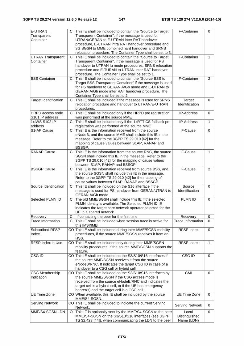
ETSI
ETSI TS 129 274 V12.6.0 (2014-10)1473GPP TS 29.274 version 12.6.0 Release 12
E-UTRAN Transparent Container
C This IE shall be included to contain the "Source to Target Transparent Container", if the message is used for UTRAN/GERAN to E-UTRAN inter RAT handover procedure, E-UTRAN intra RAT handover procedure and 3G SGSN to MME combined hard handover and SRNS relocation procedure. The Container Type shall be set to 3.
F-Container 0
UTRAN Transparent Container
C This IE shall be included to contain the "Source to Target Transparent Container", if the message is used for PS handover to UTRAN Iu mode procedures, SRNS relocation procedure and E-TURAN to UTRAN inter RAT handover procedure. The Container Type shall be set to 1.
F-Container 1
BSS Container C This IE shall be included to contain the "Source BSS to Target BSS Transparent Container" if the message is used for PS handover to GERAN A/Gb mode and E-UTRAN to GERAN A/Gb mode inter RAT handover procedure. The Container Type shall be set to 2.
F-Container 2
Target Identification C This IE shall be included if the message is used for SRNS relocation procedure and handover to UTRAN/E-UTRAN procedures.
Target Identification
0
HRPD access node S101 IP address
C This IE shall be included only if the HRPD pre registration was performed at the source MME
IP-Address 0
1xIWS S102 IP address
C This IE shall be included only if the 1xRTT CS fallback pre registration was performed at the source MME
IP-Address 1
S1-AP Cause C This IE is the information received from the source eNodeB, and the source MME shall include this IE in the message. Refer to the 3GPP TS 29.010 [42] for the mapping of cause values between S1AP, RANAP and BSSGP.
F-Cause 0
RANAP Cause C This IE is the information from the source RNC, the source SGSN shall include this IE in the message. Refer to the 3GPP TS 29.010 [42] for the mapping of cause values between S1AP, RANAP and BSSGP.
F-Cause 1
BSSGP Cause C This IE is the information received from source BSS, and the source SGSN shall include this IE in the message. Refer to the 3GPP TS 29.010 [42] for the mapping of cause values between S1AP, RANAP and BSSGP.
F-Cause 2
Source Identification C This IE shall be included on the S16 interface if the message is used for PS handover from GERAN/UTRAN to GERAN A/Gb mode.
Source Identification
0
Selected PLMN ID C The old MME/SGSN shall include this IE if the selected PLMN identity is available. The Selected PLMN ID IE indicates the target core network operator selected for the UE in a shared network.
PLMN ID 0
Recovery C If contacting the peer for the first time Recovery 0 Trace Information C This IE shall be included when session trace is active for
this IMSI/IMEI. Trace Information 0
Subscribed RFSP Index
CO This IE shall be included during inter-MME/SGSN mobility procedures, if the source MME/SGSN receives it from an HSS.
RFSP Index 0
RFSP Index in Use CO This IE shall be included only during inter-MME/SGSN mobility procedures, if the source MME/SGSN supports the feature.
RFSP Index 1
CSG ID CO This IE shall be included on the S3/S10/S16 interfaces if the source MME/SGSN receives it from the source eNodeB/RNC. It indicates the target CSG ID in case of a handover to a CSG cell or hybrid cell.
CSG ID 0
CSG Membership Indication
CO This IE shall be included on the S3/S10/S16 interfaces by the source MME/SGSN if the CSG access mode is received from the source eNodeB/RNC and indicates the target cell is a hybrid cell, or if the UE has emergency bearer(s) and the target cell is a CSG cell.
CMI 0
UE Time Zone CO When available, this IE shall be included by the source MME/S4-SGSN.
UE Time Zone 0
Serving Network
CO This IE shall be included to indicate the current Serving Network. Serving Network 0
MME/S4-SGSN LDN O This IE is optionally sent by the MME/S4-SGSN to the peer MME/S4-SGSN on the S3/S10/S16 interfaces (see 3GPP TS 32.423 [44]), when communicating the LDN to the peer
Local Distinguished Name (LDN)
0
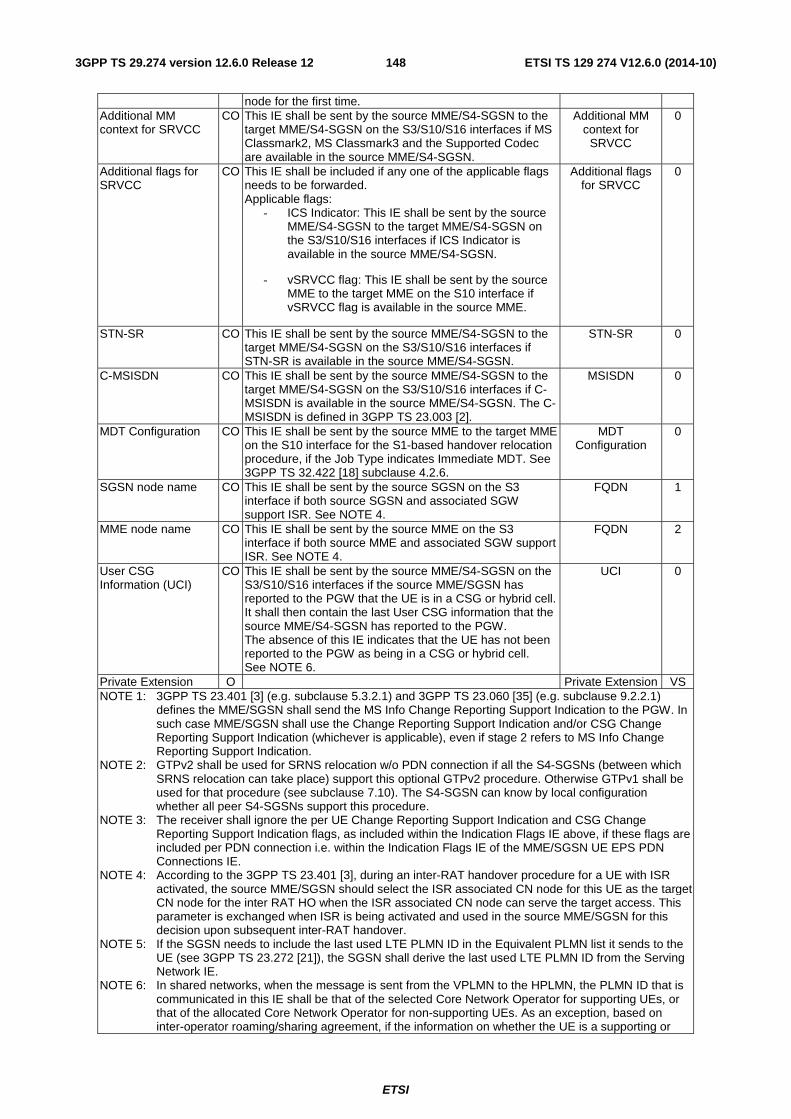
ETSI
ETSI TS 129 274 V12.6.0 (2014-10)1483GPP TS 29.274 version 12.6.0 Release 12
node for the first time. Additional MM context for SRVCC
CO This IE shall be sent by the source MME/S4-SGSN to the target MME/S4-SGSN on the S3/S10/S16 interfaces if MS Classmark2, MS Classmark3 and the Supported Codec are available in the source MME/S4-SGSN.
Additional MM context for
SRVCC
0
Additional flags for SRVCC
CO This IE shall be included if any one of the applicable flags needs to be forwarded. Applicable flags:
- ICS Indicator: This IE shall be sent by the source MME/S4-SGSN to the target MME/S4-SGSN on the S3/S10/S16 interfaces if ICS Indicator is available in the source MME/S4-SGSN.
- vSRVCC flag: This IE shall be sent by the source MME to the target MME on the S10 interface if vSRVCC flag is available in the source MME.
Additional flags for SRVCC
0
STN-SR CO This IE shall be sent by the source MME/S4-SGSN to the target MME/S4-SGSN on the S3/S10/S16 interfaces if STN-SR is available in the source MME/S4-SGSN.
STN-SR 0
C-MSISDN CO This IE shall be sent by the source MME/S4-SGSN to the target MME/S4-SGSN on the S3/S10/S16 interfaces if C-MSISDN is available in the source MME/S4-SGSN. The C-MSISDN is defined in 3GPP TS 23.003 [2].
MSISDN 0
MDT Configuration CO This IE shall be sent by the source MME to the target MME on the S10 interface for the S1-based handover relocation procedure, if the Job Type indicates Immediate MDT. See 3GPP TS 32.422 [18] subclause 4.2.6.
MDT Configuration
0
SGSN node name CO This IE shall be sent by the source SGSN on the S3 interface if both source SGSN and associated SGW support ISR. See NOTE 4.
FQDN 1
MME node name CO This IE shall be sent by the source MME on the S3 interface if both source MME and associated SGW support ISR. See NOTE 4.
FQDN 2
User CSG Information (UCI)
CO This IE shall be sent by the source MME/S4-SGSN on the S3/S10/S16 interfaces if the source MME/SGSN has reported to the PGW that the UE is in a CSG or hybrid cell. It shall then contain the last User CSG information that the source MME/S4-SGSN has reported to the PGW. The absence of this IE indicates that the UE has not been reported to the PGW as being in a CSG or hybrid cell. See NOTE 6.
UCI 0
Private Extension O Private Extension VS NOTE 1: 3GPP TS 23.401 [3] (e.g. subclause 5.3.2.1) and 3GPP TS 23.060 [35] (e.g. subclause 9.2.2.1)
defines the MME/SGSN shall send the MS Info Change Reporting Support Indication to the PGW. In such case MME/SGSN shall use the Change Reporting Support Indication and/or CSG Change Reporting Support Indication (whichever is applicable), even if stage 2 refers to MS Info Change Reporting Support Indication.
NOTE 2: GTPv2 shall be used for SRNS relocation w/o PDN connection if all the S4-SGSNs (between which SRNS relocation can take place) support this optional GTPv2 procedure. Otherwise GTPv1 shall be used for that procedure (see subclause 7.10). The S4-SGSN can know by local configuration whether all peer S4-SGSNs support this procedure.
NOTE 3: The receiver shall ignore the per UE Change Reporting Support Indication and CSG Change Reporting Support Indication flags, as included within the Indication Flags IE above, if these flags are included per PDN connection i.e. within the Indication Flags IE of the MME/SGSN UE EPS PDN Connections IE.
NOTE 4: According to the 3GPP TS 23.401 [3], during an inter-RAT handover procedure for a UE with ISR activated, the source MME/SGSN should select the ISR associated CN node for this UE as the target CN node for the inter RAT HO when the ISR associated CN node can serve the target access. This parameter is exchanged when ISR is being activated and used in the source MME/SGSN for this decision upon subsequent inter-RAT handover.
NOTE 5: If the SGSN needs to include the last used LTE PLMN ID in the Equivalent PLMN list it sends to the UE (see 3GPP TS 23.272 [21]), the SGSN shall derive the last used LTE PLMN ID from the Serving Network IE.
NOTE 6: In shared networks, when the message is sent from the VPLMN to the HPLMN, the PLMN ID that is communicated in this IE shall be that of the selected Core Network Operator for supporting UEs, or that of the allocated Core Network Operator for non-supporting UEs. As an exception, based on inter-operator roaming/sharing agreement, if the information on whether the UE is a supporting or
ETSI
ETSI TS 129 274 V12.6.0 (2014-10)1493GPP TS 29.274 version 12.6.0 Release 12
non-supporting UE is available, the PLMN ID that is communicated to the HPLMN for non-supporting UEs shall be the Common PLMN ID. In shared networks, when the MME/S4-SGSN and PGW pertain to the same PLMN, the Primary PLMN ID shall be communicated in the ECGI to the PGW, and the Common PLMN ID shall be communicated in SAI/CGI to the PGW, for both supporting and non-supporting UEs. The Core Network Operator PLMN ID (selected by the UE for supporting UEs or allocated by the network for non-supporting UEs) shall be communicated in the TAI, RAI, UCI and the Serving Network. See subclause 4.4 of 3GPP TS 23.251 [55].
The PDN Connection grouped IE shall be coded as depicted in Table 7.3.1-2.
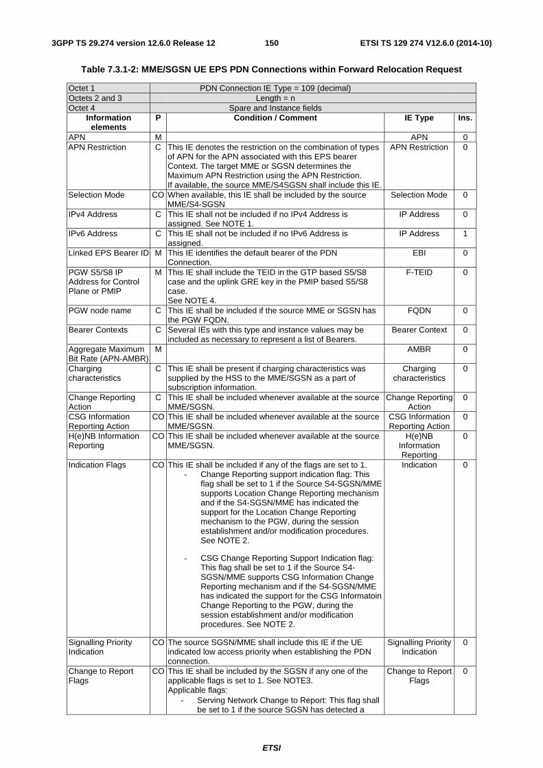
ETSI
ETSI TS 129 274 V12.6.0 (2014-10)1503GPP TS 29.274 version 12.6.0 Release 12
Table 7.3.1-2: MME/SGSN UE EPS PDN Connections within Forward Relocation Request
Octet 1 PDN Connection IE Type = 109 (decimal) Octets 2 and 3 Length = n Octet 4 Spare and Instance fields
Information elements
P Condition / Comment IE Type Ins.
APN M APN 0 APN Restriction C This IE denotes the restriction on the combination of types
of APN for the APN associated with this EPS bearer Context. The target MME or SGSN determines the Maximum APN Restriction using the APN Restriction. If available, the source MME/S4SGSN shall include this IE.
APN Restriction 0
Selection Mode CO When available, this IE shall be included by the source MME/S4-SGSN
Selection Mode 0
IPv4 Address C This IE shall not be included if no IPv4 Address is assigned. See NOTE 1.
IP Address 0
IPv6 Address C This IE shall not be included if no IPv6 Address is assigned.
IP Address 1
Linked EPS Bearer ID M This IE identifies the default bearer of the PDN Connection.
EBI 0
PGW S5/S8 IP Address for Control Plane or PMIP
M This IE shall include the TEID in the GTP based S5/S8 case and the uplink GRE key in the PMIP based S5/S8 case. See NOTE 4.
F-TEID 0
PGW node name C This IE shall be included if the source MME or SGSN has the PGW FQDN.
FQDN 0
Bearer Contexts C Several IEs with this type and instance values may be included as necessary to represent a list of Bearers.
Bearer Context 0
Aggregate Maximum Bit Rate (APN-AMBR)
M AMBR 0
Charging characteristics
C This IE shall be present if charging characteristics was supplied by the HSS to the MME/SGSN as a part of subscription information.
Charging characteristics
0
Change Reporting Action
C This IE shall be included whenever available at the source MME/SGSN.
Change Reporting Action
0
CSG Information Reporting Action
CO This IE shall be included whenever available at the source MME/SGSN.
CSG Information Reporting Action
0
H(e)NB Information Reporting
CO This IE shall be included whenever available at the source MME/SGSN.
H(e)NB Information Reporting
0
Indication Flags CO This IE shall be included if any of the flags are set to 1. - Change Reporting support indication flag: This
flag shall be set to 1 if the Source S4-SGSN/MME supports Location Change Reporting mechanism and if the S4-SGSN/MME has indicated the support for the Location Change Reporting mechanism to the PGW, during the session establishment and/or modification procedures. See NOTE 2.
- CSG Change Reporting Support Indication flag: This flag shall be set to 1 if the Source S4-SGSN/MME supports CSG Information Change Reporting mechanism and if the S4-SGSN/MME has indicated the support for the CSG Informatoin Change Reporting to the PGW, during the session establishment and/or modification procedures. See NOTE 2.
Indication 0
Signalling Priority Indication
CO The source SGSN/MME shall include this IE if the UE indicated low access priority when establishing the PDN connection.
Signalling Priority Indication
0
Change to Report Flags
CO This IE shall be included by the SGSN if any one of the applicable flags is set to 1. See NOTE3. Applicable flags:
- Serving Network Change to Report: This flag shall be set to 1 if the source SGSN has detected a
Change to Report Flags
0
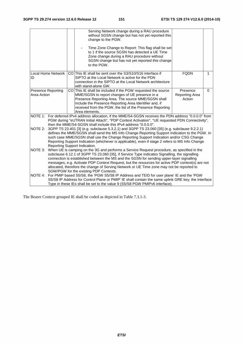
ETSI
ETSI TS 129 274 V12.6.0 (2014-10)1513GPP TS 29.274 version 12.6.0 Release 12
Serving Network change during a RAU procedure without SGSN change but has not yet reported this change to the PGW.
- Time Zone Change to Report: This flag shall be set to 1 if the source SGSN has detected a UE Time Zone change during a RAU procedure without SGSN change but has not yet reported this change to the PGW.
Local Home Network ID
CO This IE shall be sent over the S3/S10/S16 interface if SIPTO at the Local Network is active for the PDN connection in the SIPTO at the Local Network architecture with stand-alone GW.
FQDN 1
Presence Reporting Area Action
CO This IE shall be included if the PGW requested the source MME/SGSN to report changes of UE presence in a Presence Reporting Area. The source MME/SGSN shall include the Presence Reporting Area Identifier and, if received from the PGW, the list of the Presence Reporting Area elements.
Presence Reporting Area
Action
0
NOTE 1: For deferred IPv4 address allocation, if the MME/S4-SGSN receives the PDN address "0.0.0.0" from PGW during "eUTRAN Initial Attach", "PDP Context Activation", "UE requested PDN Connectivity", then the MME/S4-SGSN shall include this IPv4 address "0.0.0.0".
NOTE 2: 3GPP TS 23.401 [3] (e.g. subclause 5.3.2.1) and 3GPP TS 23.060 [35] (e.g. subclause 9.2.2.1) defines the MME/SGSN shall send the MS Info Change Reporting Support Indication to the PGW. In such case MME/SGSN shall use the Change Reporting Support Indication and/or CSG Change Reporting Support Indication (whichever is applicable), even if stage 2 refers to MS Info Change Reporting Support Indication.
NOTE 3: When UE is camping on the 3G and performs a Service Request procedure, as specified in the subclause 6.12.1 of 3GPP TS 23.060 [35], if Service Type indicates Signalling, the signalling connection is established between the MS and the SGSN for sending upper-layer signalling messages, e.g. Activate PDP Context Request, but the resources for active PDP context(s) are not allocated, therefore the change of Serving Network or UE Time zone may not be reported to SGW/PGW for the existing PDP Contexts.
NOTE 4: For PMIP based S5/S8, the 'PGW S5/S8 IP Address and TEID for user plane' IE and the 'PGW S5/S8 IP Address for Control Plane or PMIP' IE shall contain the same uplink GRE key; the Interface Type in these IEs shall be set to the value 9 (S5/S8 PGW PMIPv6 interface).
The Bearer Context grouped IE shall be coded as depicted in Table 7.3.1-3.
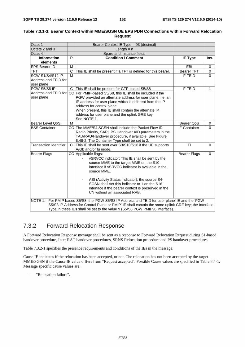
ETSI
ETSI TS 129 274 V12.6.0 (2014-10)1523GPP TS 29.274 version 12.6.0 Release 12
Table 7.3.1-3: Bearer Context within MME/SGSN UE EPS PDN Connections within Forward Relocation Request
Octet 1 Bearer Context IE Type = 93 (decimal) Octets 2 and 3 Length = n Octet 4 Spare and Instance fields
Information elements
P Condition / Comment IE Type Ins.
EPS Bearer ID M EBI 0 TFT C This IE shall be present if a TFT is defined for this bearer. Bearer TFT 0 SGW S1/S4/S12 IP Address and TEID for user plane
M F-TEID 0
PGW S5/S8 IP Address and TEID for user plane
C This IE shall be present for GTP based S5/S8 F-TEID 1 CO For PMIP-based S5/S8, this IE shall be included if the
PGW provided an alternate address for user plane, i.e. an IP address for user plane which is different from the IP address for control plane. When present, this IE shall contain the alternate IP address for user plane and the uplink GRE key. See NOTE 1.
Bearer Level QoS M Bearer QoS 0 BSS Container CO The MME/S4 SGSN shall include the Packet Flow ID,
Radio Priority, SAPI, PS Handover XID parameters in the TAU/RAU/Handover procedure, if available. See Figure 8.48-2. The Container Type shall be set to 2.
F-Container 0
Transaction Identifier C This IE shall be sent over S3/S10/S16 if the UE supports A/Gb and/or Iu mode.
TI 0
Bearer Flags CO Applicable flags: - vSRVCC indicator: This IE shall be sent by the
source MME to the target MME on the S10 interface if vSRVCC indicator is available in the source MME.
- ASI (Activity Status Indicator): the source S4-SGSN shall set this indicator to 1 on the S16 interface if the bearer context is preserved in the CN without an associated RAB.
Bearer Flags 0
NOTE 1: For PMIP based S5/S8, the 'PGW S5/S8 IP Address and TEID for user plane' IE and the 'PGW S5/S8 IP Address for Control Plane or PMIP' IE shall contain the same uplink GRE key; the Interface Type in these IEs shall be set to the value 9 (S5/S8 PGW PMIPv6 interface).
7.3.2 Forward Relocation Response
A Forward Relocation Response message shall be sent as a response to Forward Relocation Request during S1-based handover procedure, Inter RAT handover procedures, SRNS Relocation procedure and PS handover procedures.
Table 7.3.2-1 specifies the presence requirements and conditions of the IEs in the message.
Cause IE indicates if the relocation has been accepted, or not. The relocation has not been accepted by the target MME/SGSN if the Cause IE value differs from "Request accepted". Possible Cause values are specified in Table 8.4-1. Message specific cause values are:
- "Relocation failure".
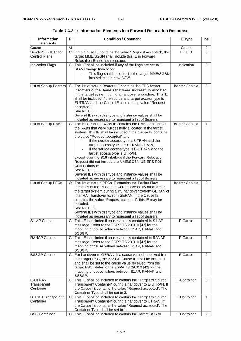
ETSI
ETSI TS 129 274 V12.6.0 (2014-10)1533GPP TS 29.274 version 12.6.0 Release 12
Table 7.3.2-1: Information Elements in a Forward Relocation Response
Information elements
P Condition / Comment IE Type Ins.
Cause M Cause 0 Sender's F-TEID for Control Plane
C If the Cause IE contains the value "Request accepted", the target MME/SGSN shall include this IE in Forward Relocation Response message.
F-TEID 0
Indication Flags C This IE shall be included if any of the flags are set to 1. SGW Change Indication:
- This flag shall be set to 1 if the target MME/SGSN has selected a new SGW.
Indication 0
List of Set-up Bearers C The list of set-up Bearers IE contains the EPS bearer Identifiers of the Bearers that were successfully allocated in the target system during a handover procedure. This IE shall be included if the source and target access type is EUTRAN and the Cause IE contains the value "Request accepted". See NOTE 1. Several IEs with this type and instance values shall be included as necessary to represent a list of Bearers.
Bearer Context 0
List of Set-up RABs C The list of set-up RABs IE contains the RAB Identifiers of the RABs that were successfully allocated in the target system. This IE shall be included if the Cause IE contains the value "Request accepted" and
- If the source access type is UTRAN and the target access type is E-UTRAN/UTRAN,
- If the source access type is E-UTRAN and the target access type is UTRAN,
except over the S16 interface if the Forward Relocation Request did not include the MME/SGSN UE EPS PDN Connections IE. See NOTE 1. Several IEs with this type and instance values shall be included as necessary to represent a list of Bearers.
Bearer Context 1
List of Set-up PFCs O The list of set-up PFCs IE contains the Packet Flow Identifies of the PFCs that were successfully allocated in the target system during a PS handover to/from GERAN or inter RAT handover to/from GERAN. If the Cause IE contains the value "Request accepted", this IE may be included. See NOTE 1. Several IEs with this type and instance values shall be included as necessary to represent a list of Bearers.
Bearer Context 2
S1-AP Cause
C This IE is included if cause value is contained in S1-AP message. Refer to the 3GPP TS 29.010 [42] for the mapping of cause values between S1AP, RANAP and BSSGP.
F-Cause 0
RANAP Cause C This IE is included if cause value is contained in RANAP message. Refer to the 3GPP TS 29.010 [42] for the mapping of cause values between S1AP, RANAP and BSSGP.
F-Cause 1
BSSGP Cause C For handover to GERAN, if a cause value is received from the Target BSC, the BSSGP Cause IE shall be included and shall be set to the cause value received from the target BSC. Refer to the 3GPP TS 29.010 [42] for the mapping of cause values between S1AP, RANAP and BSSGP.
F-Cause 2
E-UTRAN Transparent Container
C This IE shall be included to contain the "Target to Source Transparent Container" during a handover to E-UTRAN. If the Cause IE contains the value "Request accepted". The Container Type shall be set to 3.
F-Container 0
UTRAN Transparent Container
C This IE shall be included to contain the "Target to Source Transparent Container" during a handover to UTRAN. If the Cause IE contains the value "Request accepted". The Container Type shall be set to 1.
F-Container 1
BSS Container C This IE shall be included to contain the Target BSS to F-Container 2
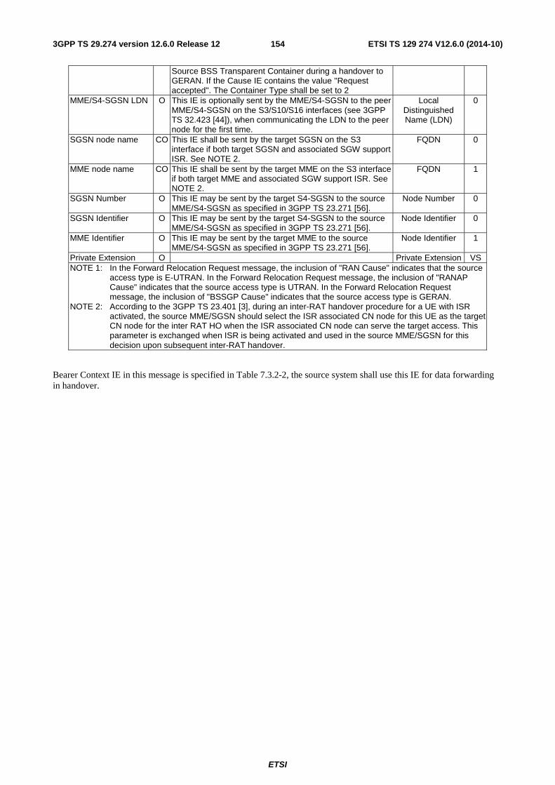
ETSI
ETSI TS 129 274 V12.6.0 (2014-10)1543GPP TS 29.274 version 12.6.0 Release 12
Source BSS Transparent Container during a handover to GERAN. If the Cause IE contains the value "Request accepted". The Container Type shall be set to 2
MME/S4-SGSN LDN O This IE is optionally sent by the MME/S4-SGSN to the peer MME/S4-SGSN on the S3/S10/S16 interfaces (see 3GPP TS 32.423 [44]), when communicating the LDN to the peer node for the first time.
Local Distinguished Name (LDN)
0
SGSN node name CO This IE shall be sent by the target SGSN on the S3 interface if both target SGSN and associated SGW support ISR. See NOTE 2.
FQDN 0
MME node name CO This IE shall be sent by the target MME on the S3 interface if both target MME and associated SGW support ISR. See NOTE 2.
FQDN 1
SGSN Number O This IE may be sent by the target S4-SGSN to the source MME/S4-SGSN as specified in 3GPP TS 23.271 [56].
Node Number 0
SGSN Identifier O This IE may be sent by the target S4-SGSN to the source MME/S4-SGSN as specified in 3GPP TS 23.271 [56].
Node Identifier 0
MME Identifier O This IE may be sent by the target MME to the source MME/S4-SGSN as specified in 3GPP TS 23.271 [56].
Node Identifier 1
Private Extension O Private Extension VS NOTE 1: In the Forward Relocation Request message, the inclusion of "RAN Cause" indicates that the source
access type is E-UTRAN. In the Forward Relocation Request message, the inclusion of "RANAP Cause" indicates that the source access type is UTRAN. In the Forward Relocation Request message, the inclusion of "BSSGP Cause" indicates that the source access type is GERAN.
NOTE 2: According to the 3GPP TS 23.401 [3], during an inter-RAT handover procedure for a UE with ISR activated, the source MME/SGSN should select the ISR associated CN node for this UE as the target CN node for the inter RAT HO when the ISR associated CN node can serve the target access. This parameter is exchanged when ISR is being activated and used in the source MME/SGSN for this decision upon subsequent inter-RAT handover.
Bearer Context IE in this message is specified in Table 7.3.2-2, the source system shall use this IE for data forwarding in handover.
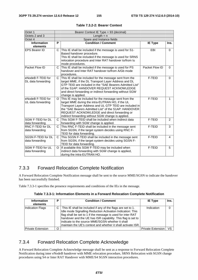
ETSI
ETSI TS 129 274 V12.6.0 (2014-10)1553GPP TS 29.274 version 12.6.0 Release 12
Table 7.3.2-2: Bearer Context
Octet 1 Bearer Context IE Type = 93 (decimal) Octets 2 and 3 Length = n Octet 4 Spare and Instance fields
Information elements
P Condition / Comment IE Type Ins.
EPS Bearer ID C This IE shall be included if the message is used for S1-Based handover procedure. This IE shall be included if the message is used for SRNS relocation procedure and Inter RAT handover to/from Iu mode procedures.
EBI 0
Packet Flow ID C This IE shall be included if the message is used for PS handover and Inter RAT handover to/from A/Gb mode procedures.
Packet Flow ID 0
eNodeB F-TEID for DL data forwarding
C This IE shall be included for the message sent from the target MME, if the DL Transport Layer Address and DL GTP TEID are included in the "SAE Bearers Admitted List" of the S1AP: HANDOVER REQUEST ACKNOWLEDGE and direct forwarding or indirect forwarding without SGW change is applied.
F-TEID 0
eNodeB F-TEID for UL data forwarding
O This IE may be included for the message sent from the target MME during the intra-EUTRAN HO, if the UL Transport Layer Address and UL GTP TEID are included in the "SAE Bearers Admitted List" of the S1AP: HANDOVER REQUEST ACKNOWLEDGE and direct forwarding or indirect forwarding without SGW change is applied.
F-TEID 1
SGW F-TEID for DL data forwarding
C This SGW F-TEID shall be included when indirect data forwarding with SGW change is applied.
F-TEID 2
RNC F-TEID for DL data forwarding
C This RNC F-TEID shall be included in the message sent from SGSN, if the target system decides using RNC F-TEID for data forwarding.
F-TEID 3
SGSN F-TEID for DL data forwarding
C This SGSN F-TEID shall be included in the message sent from SGSN, if the target system decides using SGSN F-TEID for data forwarding.
F-TEID 4
SGW F-TEID for UL data forwarding
O If available this SGW F-TEID may be included when indirect data forwarding with SGW change is applied, during the intra-EUTRAN HO.
F-TEID 5
7.3.3 Forward Relocation Complete Notification
A Forward Relocation Complete Notification message shall be sent to the source MME/SGSN to indicate the handover has been successfully finished.
Table 7.3.3-1 specifies the presence requirements and conditions of the IEs in the message.
Table 7.3.3-1: Information Elements in a Forward Relocation Complete Notification
Information elements
P Condition / Comment IE Type Ins.
Indication Flags C This IE shall be included if any of the flags are set to 1. Idle mode Signalling Reduction Activation Indication: This flag shall be set to 1 if the message is used for inter RAT handover and the UE has ISR capability. This flag is set to indicate to the source MME/SGSN whether it shall maintain the UE's context and whether it shall activate ISR.
Indication 0
Private Extension O Private Extension VS
7.3.4 Forward Relocation Complete Acknowledge
A Forward Relocation Complete Acknowledge message shall be sent as a response to Forward Relocation Complete Notification during inter eNodeB handover with MME relocation procedure, SRNS Relocation with SGSN change procedures using S4 or Inter RAT Handover with MME/S4 SGSN interaction procedures.
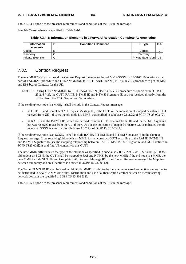
ETSI
ETSI TS 129 274 V12.6.0 (2014-10)1563GPP TS 29.274 version 12.6.0 Release 12
Table 7.3.4-1 specifies the presence requirements and conditions of the IEs in the message.
Possible Cause values are specified in Table 8.4-1.
Table 7.3.4-1: Information Elements in a Forward Relocation Complete Acknowledge
Information elements
P Condition / Comment IE Type Ins.
Cause M Cause 0 Recovery O Recovery 0 Private Extension O Private Extension VS
7.3.5 Context Request
The new MME/SGSN shall send the Context Request message to the old MME/SGSN on S3/S16/S10 interface as a part of TAU/RAU procedure and UTRAN/GERAN to E-UTRAN/UTRAN (HSPA) SRVCC procedure to get the MM and EPS bearer Contexts for the UE.
NOTE 1: During UTRAN/GERAN to E-UTRAN/UTRAN (HSPA) SRVCC procedure as specified in 3GPP TS 23.216 [43], the GUTI, RAI IE, P-TMSI IE and P-TMSI Signature IE, are not received directly from the UE but from the MSC Server over Sv interface.
If the sending/new node is a MME, it shall include in the Context Request message:
- the GUTI IE and Complete TAU Request Message IE, if the GUTI or the indication of mapped or native GUTI received from UE indicates the old node is a MME, as specified in subclause 2.8.2.2.2 of 3GPP TS 23.003 [2].
- the RAI IE and the P-TMSI IE, which are derived from the GUTI received from UE, and the P-TMSI Signature that was received intact from the UE, if the GUTI or the indication of mapped or native GUTI indicates the old node is an SGSN as specified in subclause 2.8.2.2.2 of 3GPP TS 23.003 [2].
If the sending/new node is an SGSN, it shall include RAI IE, P-TMSI IE and P-TMSI Signature IE in the Context Request message. If the receiving/old node is an MME, it shall construct GUTI according to the RAI IE, P-TMSI IE and P-TMSI Signature IE (see the mapping relationship between RAI, P-TMSI, P-TMSI signature and GUTI defined in 3GPP TS23.003[2]), and find UE context via this GUTI.
The new MME differentiates the type of the old node as specified in subclause 2.8.2.2.2 of 3GPP TS 23.003 [2]. If the old node is an SGSN, the GUTI shall be mapped to RAI and P-TMSI by the new MME; if the old node is a MME, the new MME include GUTI IE and Complete TAU Request Message IE in the Context Request message. The Mapping between temporary and area identities is defined in 3GPP TS 23.003 [2].
The Target PLMN ID IE shall be used in old SGSN/MME in order to decide whether un-used authentication vectors to be distributed to new SGSN/MME or not. Distribution and use of authentication vectors between different serving network domains are specified in 3GPP TS 33.401 [12].
Table 7.3.5-1 specifies the presence requirements and conditions of the IEs in the message.
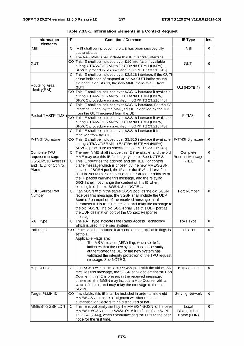
ETSI
ETSI TS 129 274 V12.6.0 (2014-10)1573GPP TS 29.274 version 12.6.0 Release 12
Table 7.3.5-1: Information Elements in a Context Request
Information elements
P Condition / Comment IE Type Ins.
IMSI C IMSI shall be included if the UE has been successfully authenticated.
IMSI 0
GUTI
C The New MME shall include this IE over S10 interface.
GUTI 0 CO This IE shall be included over S10 interface if available during UTRAN/GERAN to E-UTRAN/UTRAN (HSPA) SRVCC procedure as specified in 3GPP TS 23.216 [43].
Routeing Area Identity(RAI)
C This IE shall be included over S3/S16 interface, if the GUTI or the indication of mapped or native GUTI indicates the old node is an SGSN, the new MME maps this IE from GUTI. ULI (NOTE 4) 0
CO This IE shall be included over S3/S16 interface if available during UTRAN/GERAN to E-UTRAN/UTRAN (HSPA) SRVCC procedure as specified in 3GPP TS 23.216 [43].
Packet TMSI(P-TMSI)
C This IE shall be included over S3/S16 interface. For the S3 interface, if sent by the MME, this IE is derived by the MME from the GUTI received from the UE.
P-TMSI 0 CO This IE shall be included over S3/S16 interface if available
during UTRAN/GERAN to E-UTRAN/UTRAN (HSPA) SRVCC procedure as specified in 3GPP TS 23.216 [43].
P-TMSI Signature
C This IE shall be included over S3/S16 interface if it is received from the UE.
P-TMSI Signature 0 CO This IE shall be included over S3/S16 interface if available during UTRAN/GERAN to E-UTRAN/UTRAN (HSPA) SRVCC procedure as specified in 3GPP TS 23.216 [43].
Complete TAU request message
C The new MME shall include this IE if available, and the old MME may use this IE for integrity check. See NOTE 3.
Complete Request Message
0
S3/S16/S10 Address and TEID for Control Plane
C This IE specifies the address and the TEID for control plane message which is chosen by the new MME/SGSN. In case of SGSN pool, the IPv4 or the IPv6 address field shall be set to the same value of the Source IP address of the IP packet carrying this message, and the relaying SGSN shall not change the content of this IE when sending it to the old SGSN. See NOTE 1.
F-TEID 0
UDP Source Port Number
C If an SGSN within the same SGSN pool as the old SGSN receives this message, the SGSN shall include the UDP Source Port number of the received message in this parameter if this IE is not present and relay the message to the old SGSN. The old SGSN shall use this UDP port as the UDP destination port of the Context Response message.
Port Number 0
RAT Type C The RAT Type indicates the Radio Access Technology which is used in the new system.
RAT Type 0
Indication CO his IE shall be included if any one of the applicable flags is set to 1. Applicable Flags are:
- The MS Validated (MSV) flag, when set to 1, indicates that the new system has successfully authenticated the UE, or the new system has validated the integrity protection of the TAU request message. See NOTE 3.
Indication 0
Hop Counter O If an SGSN within the same SGSN pool with the old SGSN receives this message, the SGSN shall decrement the Hop Counter if this IE is present in the received message; otherwise, the SGSN may include a Hop Counter with a value of max-1, and may relay the message to the old SGSN.
Hop Counter 0
Target PLMN ID CO If available, this IE shall be included in order to allow old MME/SGSN to make a judgment whether un-used authentication vectors to be distributed or not.
Serving Network 0
MME/S4-SGSN LDN O This IE is optionally sent by the MME/S4-SGSN to the peer MME/S4-SGSN on the S3/S10/S16 interfaces (see 3GPP TS 32.423 [44]), when communicating the LDN to the peer node for the first time.
Local Distinguished Name (LDN)
0
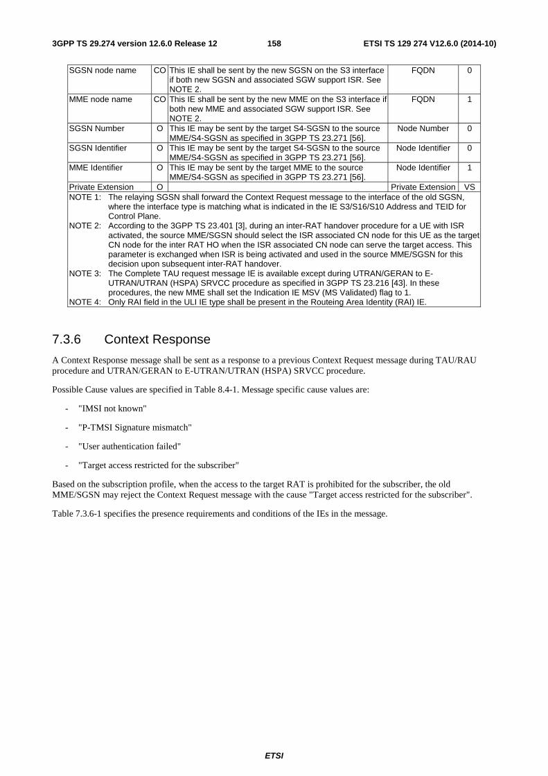
ETSI
ETSI TS 129 274 V12.6.0 (2014-10)1583GPP TS 29.274 version 12.6.0 Release 12
SGSN node name CO This IE shall be sent by the new SGSN on the S3 interface if both new SGSN and associated SGW support ISR. See NOTE 2.
FQDN 0
MME node name CO This IE shall be sent by the new MME on the S3 interface if both new MME and associated SGW support ISR. See NOTE 2.
FQDN 1
SGSN Number O This IE may be sent by the target S4-SGSN to the source MME/S4-SGSN as specified in 3GPP TS 23.271 [56].
Node Number 0
SGSN Identifier O This IE may be sent by the target S4-SGSN to the source MME/S4-SGSN as specified in 3GPP TS 23.271 [56].
Node Identifier 0
MME Identifier O This IE may be sent by the target MME to the source MME/S4-SGSN as specified in 3GPP TS 23.271 [56].
Node Identifier 1
Private Extension O Private Extension VS NOTE 1: The relaying SGSN shall forward the Context Request message to the interface of the old SGSN,
where the interface type is matching what is indicated in the IE S3/S16/S10 Address and TEID for Control Plane.
NOTE 2: According to the 3GPP TS 23.401 [3], during an inter-RAT handover procedure for a UE with ISR activated, the source MME/SGSN should select the ISR associated CN node for this UE as the target CN node for the inter RAT HO when the ISR associated CN node can serve the target access. This parameter is exchanged when ISR is being activated and used in the source MME/SGSN for this decision upon subsequent inter-RAT handover.
NOTE 3: The Complete TAU request message IE is available except during UTRAN/GERAN to E-UTRAN/UTRAN (HSPA) SRVCC procedure as specified in 3GPP TS 23.216 [43]. In these procedures, the new MME shall set the Indication IE MSV (MS Validated) flag to 1.
NOTE 4: Only RAI field in the ULI IE type shall be present in the Routeing Area Identity (RAI) IE.
7.3.6 Context Response
A Context Response message shall be sent as a response to a previous Context Request message during TAU/RAU procedure and UTRAN/GERAN to E-UTRAN/UTRAN (HSPA) SRVCC procedure.
Possible Cause values are specified in Table 8.4-1. Message specific cause values are:
- "IMSI not known"
- "P-TMSI Signature mismatch"
- "User authentication failed"
- "Target access restricted for the subscriber"
Based on the subscription profile, when the access to the target RAT is prohibited for the subscriber, the old MME/SGSN may reject the Context Request message with the cause "Target access restricted for the subscriber".
Table 7.3.6-1 specifies the presence requirements and conditions of the IEs in the message.
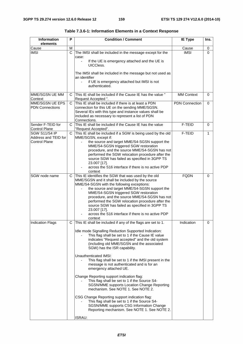
ETSI
ETSI TS 129 274 V12.6.0 (2014-10)1593GPP TS 29.274 version 12.6.0 Release 12
Table 7.3.6-1: Information Elements in a Context Response
Information elements
P Condition / Comment IE Type Ins.
Cause M Cause 0 IMSI C The IMSI shall be included in the message except for the
case: - If the UE is emergency attached and the UE is
UICCless.
The IMSI shall be included in the message but not used as an identifier
- if UE is emergency attached but IMSI is not authenticated.
IMSI 0
MME/SGSN UE MM Context
C This IE shall be included if the Cause IE has the value " Request Accepted ".
MM Context 0
MME/SGSN UE EPS PDN Connections
C This IE shall be included if there is at least a PDN connection for this UE on the sending MME/SGSN. Several IEs with this type and instance values shall be included as necessary to represent a list of PDN Connections.
PDN Connection 0
Sender F-TEID for Control Plane
C This IE shall be included if the Cause IE has the value "Request Accepted".
F-TEID 0
SGW S11/S4 IP Address and TEID for Control Plane
C This IE shall be included if a SGW is being used by the old MME/SGSN, except if:
- the source and target MME/S4-SGSN support the MME/S4-SGSN triggered SGW restoration procedure, and the source MME/S4-SGSN has not performed the SGW relocation procedure after the source SGW has failed as specified in 3GPP TS 23.007 [17].
- across the S16 interface if there is no active PDP context
F-TEID 1
SGW node name C This IE identifies the SGW that was used by the old MME/SGSN and it shall be included by the source MME/S4-SGSN with the following exceptions:
- the source and target MME/S4-SGSN support the MME/S4-SGSN triggered SGW restoration procedure, and the source MME/S4-SGSN has not performed the SGW relocation procedure after the source SGW has failed as specified in 3GPP TS 23.007 [17].
- across the S16 interface if there is no active PDP context
FQDN 0
Indication Flags C This IE shall be included if any of the flags are set to 1. Idle mode Signalling Reduction Supported Indication:
- This flag shall be set to 1 if the Cause IE value indicates "Request accepted" and the old system (including old MME/SGSN and the associated SGW) has the ISR capability.
Unauthenticated IMSI: - This flag shall be set to 1 if the IMSI present in the
message is not authenticated and is for an emergency attached UE.
Change Reporting support indication flag: - This flag shall be set to 1 if the Source S4-
SGSN/MME supports Location Change Reporting mechanism. See NOTE 1. See NOTE 2.
CSG Change Reporting support indication flag: - This flag shall be set to 1 if the Source S4-
SGSN/MME supports CSG Information Change Reporting mechanism. See NOTE 1. See NOTE 2.
ISRAU:
Indication 0
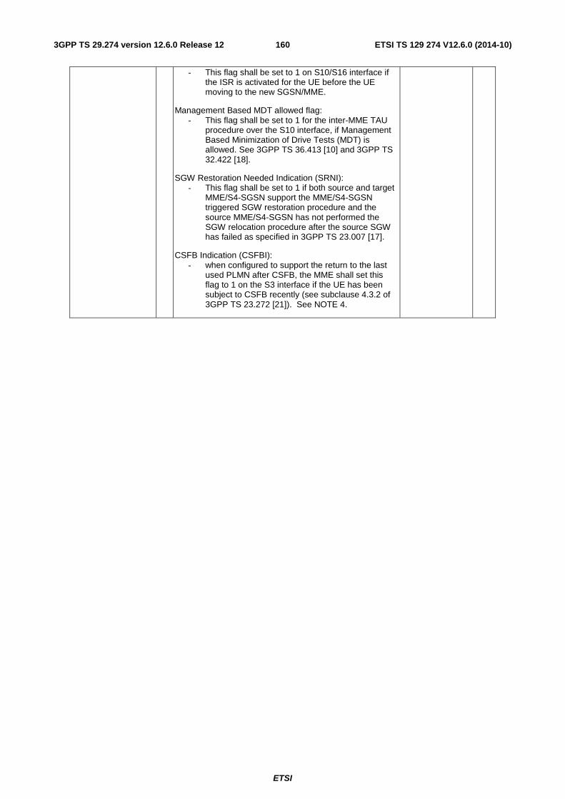
ETSI
ETSI TS 129 274 V12.6.0 (2014-10)1603GPP TS 29.274 version 12.6.0 Release 12
- This flag shall be set to 1 on S10/S16 interface if the ISR is activated for the UE before the UE moving to the new SGSN/MME.
Management Based MDT allowed flag: - This flag shall be set to 1 for the inter-MME TAU
procedure over the S10 interface, if Management Based Minimization of Drive Tests (MDT) is allowed. See 3GPP TS 36.413 [10] and 3GPP TS 32.422 [18].
SGW Restoration Needed Indication (SRNI): - This flag shall be set to 1 if both source and target
MME/S4-SGSN support the MME/S4-SGSN triggered SGW restoration procedure and the source MME/S4-SGSN has not performed the SGW relocation procedure after the source SGW has failed as specified in 3GPP TS 23.007 [17].
CSFB Indication (CSFBI): - when configured to support the return to the last
used PLMN after CSFB, the MME shall set this flag to 1 on the S3 interface if the UE has been subject to CSFB recently (see subclause 4.3.2 of 3GPP TS 23.272 [21]). See NOTE 4.

ETSI
ETSI TS 129 274 V12.6.0 (2014-10)1613GPP TS 29.274 version 12.6.0 Release 12
Trace Information C This IE shall be included when session trace is active for this IMSI/IMEI.
Trace Information 0
HRPD access node S101 IP address
C This IE shall be included only if the HRPD pre registration was performed at the old MME
IP-Address 0
1xIWS S102 IP address
C This IE shall be included only if the 1xRTT CS fallback pre registration was performed at the old MME
IP-Address 1
Subscribed RFSP Index
CO This IE shall be included only during inter-MME/SGSN mobility procedures, if the source MME/SGSN receives it from an HSS.
RFSP Index 0
RFSP Index in Use CO This IE shall be included only during inter-MME/SGSN mobility procedures, if the source MME/SGSN supports the feature.
RFSP Index 1
UE Time Zone CO When available, this IE shall be included by the source MME/S4-SGSN.
UE Time Zone 0
MME/S4-SGSN LDN O This IE is optionally sent by the MME/S4-SGSN to the peer MME/S4-SGSN on the S3/S10/S16 interfaces (see 3GPP TS 32.423 [44]), when communicating the LDN to the peer node for the first time.
Local Distinguished Name (LDN)
0
MDT Configuration CO This IE shall be sent by the source MME to the target MME on the S10 interface for inter-MME TAU procedure, if the Job Type indicates Immediate MDT. See 3GPP TS 32.422 [18] subclause 4.2.6.
MDT Configuration
0
SGSN node name CO This IE shall be sent by the old SGSN on the S3 interface if both old SGSN and associated SGW support ISR. See NOTE 3.
FQDN 1
MME node name CO This IE shall be sent by the old MME on the S3 interface if both old MME and associated SGW support ISR. See NOTE 3.
FQDN 2
User CSG Information (UCI)
CO This IE shall be sent by the source MME/S4-SGSN on the S3/S10/S16 interfaces if the source MME/SGSN has reported to the PGW that the UE is in a CSG or hybrid cell. It shall then contain the last User CSG information that the source MME/S4-SGSN has reported to the PGW. The absence of this IE indicates that the UE has not been reported to the PGW as being in a CSG or hybrid cell. See NOTE 5.
UCI 0
Private Extension O Private Extension VS NOTE 1: 3GPP TS 23.401 [3] (e.g. subclause 5.3.2.1) and 3GPP TS 23.060 [35] (e.g. subclause 9.2.2.1)
defines the MME/SGSN shall send the MS Info Change Reporting Support Indication to the PGW. In such case MME/SGSN shall use the Change Reporting Support Indication and/or CSG Change Reporting Support Indication (whichever is applicable), even if stage 2 refers to MS Info Change Reporting Support Indication.
NOTE 2: The receiver shall ignore the per UE Change Reporting Support Indication and CSG Change Reporting Support Indication flags, as included within the Indication Flags IE above, if these flags are included per PDN connection i.e. within the Indication Flags IE of the MME/SGSN UE EPS PDN Connections IE.
NOTE 3: According to the 3GPP TS 23.401 [3], during an inter-RAT handover procedure for a UE with ISR activated, the source MME/SGSN should select the ISR associated CN node for this UE as the target CN node for the inter RAT HO when the ISR associated CN node can serve the target access. This parameter is exchanged when ISR is being activated and used in the source MME/SGSN for this decision upon subsequent inter-RAT handover.
NOTE 4: If the SGSN needs to include the last used LTE PLMN ID in the Equivalent PLMN list it sends to the UE (see 3GPP TS 23.272 [21]), the SGSN shall derive the last used LTE PLMN ID from the Old RAI IE received in the RAU request message.
NOTE 5: In shared networks, when the message is sent from the VPLMN to the HPLMN, the PLMN ID that is communicated in this IE shall be that of the selected Core Network Operator for supporting UEs, or that of the allocated Core Network Operator for non-supporting UEs. As an exception, based on inter-operator roaming/sharing agreement, if the information on whether the UE is a supporting or non-supporting UE is available, the PLMN ID that is communicated to the HPLMN for non-supporting UEs shall be the Common PLMN ID. In shared networks, when the MME/S4-SGSN and PGW pertain to the same PLMN, the Primary PLMN ID shall be communicated in the ECGI to the PGW, and the Common PLMN ID shall be communicated in SAI/CGI to the PGW, for both supporting and non-supporting UEs. The Core Network Operator PLMN ID (selected by the UE for supporting UEs or allocated by the network for non-supporting UEs) shall be communicated in the TAI, RAI, UCI and the Serving Network. See subclause 4.4 of 3GPP TS 23.251 [55].

ETSI
ETSI TS 129 274 V12.6.0 (2014-10)1623GPP TS 29.274 version 12.6.0 Release 12
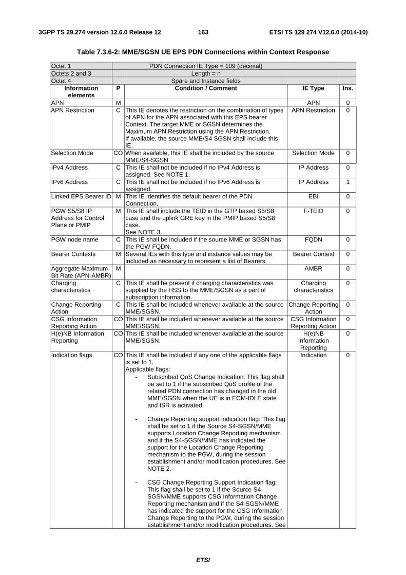
ETSI
ETSI TS 129 274 V12.6.0 (2014-10)1633GPP TS 29.274 version 12.6.0 Release 12
Table 7.3.6-2: MME/SGSN UE EPS PDN Connections within Context Response
Octet 1 PDN Connection IE Type = 109 (decimal) Octets 2 and 3 Length = n Octet 4 Spare and Instance fields
Information elements
P Condition / Comment IE Type Ins.
APN M APN 0 APN Restriction C This IE denotes the restriction on the combination of types
of APN for the APN associated with this EPS bearer Context. The target MME or SGSN determines the Maximum APN Restriction using the APN Restriction. If available, the source MME/S4 SGSN shall include this IE.
APN Restriction 0
Selection Mode CO When available, this IE shall be included by the source MME/S4-SGSN
Selection Mode 0
IPv4 Address C This IE shall not be included if no IPv4 Address is assigned. See NOTE 1.
IP Address 0
IPv6 Address C This IE shall not be included if no IPv6 Address is assigned.
IP Address 1
Linked EPS Bearer ID M This IE identifies the default bearer of the PDN Connection.
EBI 0
PGW S5/S8 IP Address for Control Plane or PMIP
M This IE shall include the TEID in the GTP based S5/S8 case and the uplink GRE key in the PMIP based S5/S8 case. See NOTE 3.
F-TEID 0
PGW node name C This IE shall be included if the source MME or SGSN has the PGW FQDN.
FQDN 0
Bearer Contexts M Several IEs with this type and instance values may be included as necessary to represent a list of Bearers.
Bearer Context 0
Aggregate Maximum Bit Rate (APN-AMBR)
M AMBR 0
Charging characteristics
C This IE shall be present if charging characteristics was supplied by the HSS to the MME/SGSN as a part of subscription information.
Charging characteristics
0
Change Reporting Action
C This IE shall be included whenever available at the source MME/SGSN.
Change Reporting Action
0
CSG Information Reporting Action
CO This IE shall be included whenever available at the source MME/SGSN.
CSG Information Reporting Action
0
H(e)NB Information Reporting
CO This IE shall be included whenever available at the source MME/SGSN.
H(e)NB Information Reporting
0
Indication flags CO This IE shall be included if any one of the applicable flags is set to 1. Applicable flags:
- Subscribed QoS Change Indication: This flag shall be set to 1 if the subscribed QoS profile of the related PDN connection has changed in the old MME/SGSN when the UE is in ECM-IDLE state and ISR is activated.
- Change Reporting support indication flag: This flag shall be set to 1 if the Source S4-SGSN/MME supports Location Change Reporting mechanism and if the S4-SGSN/MME has indicated the support for the Location Change Reporting mechanism to the PGW, during the session establishment and/or modification procedures. See NOTE 2.
- CSG Change Reporting Support Indication flag: This flag shall be set to 1 if the Source S4-SGSN/MME supports CSG Information Change Reporting mechanism and if the S4-SGSN/MME has indicated the support for the CSG Information Change Reporting to the PGW, during the session establishment and/or modification procedures. See
Indication 0
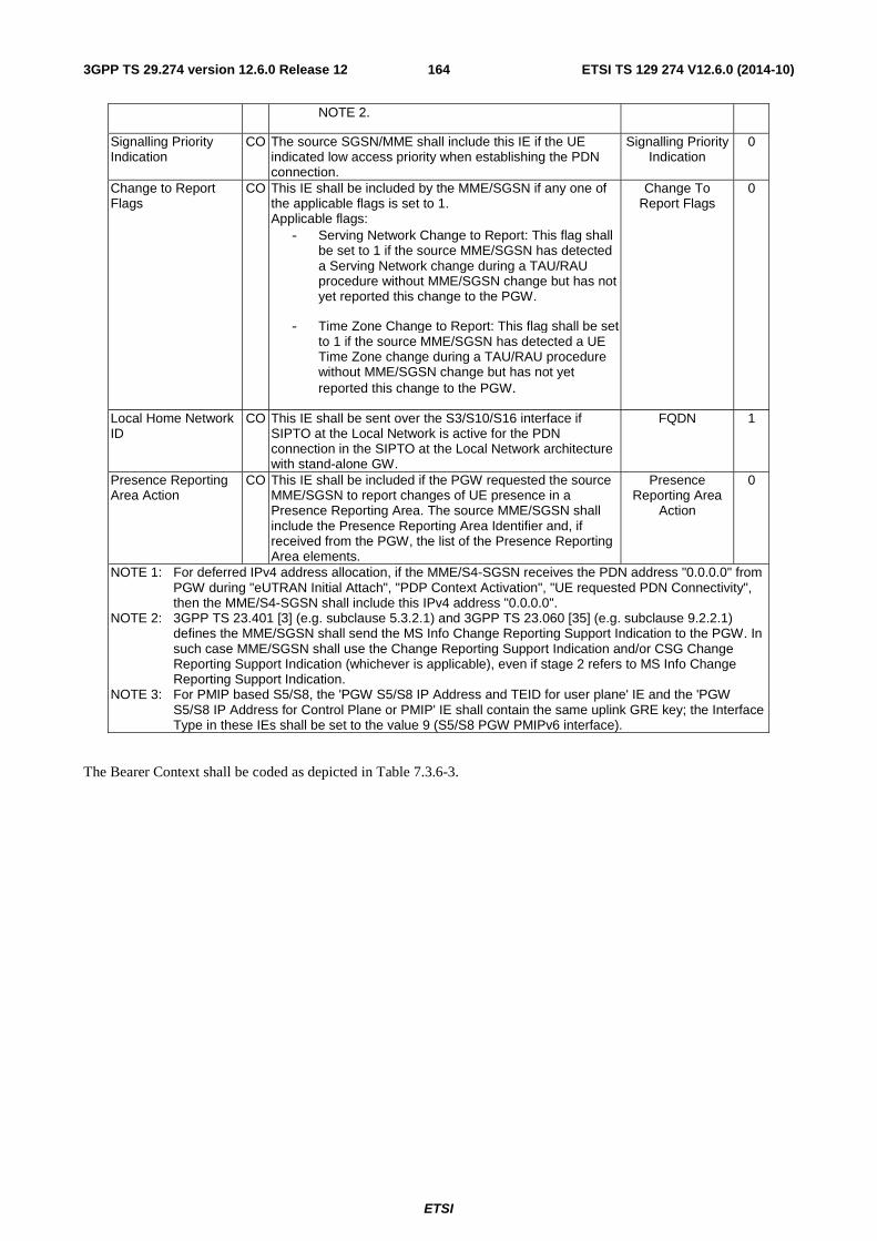
ETSI
ETSI TS 129 274 V12.6.0 (2014-10)1643GPP TS 29.274 version 12.6.0 Release 12
NOTE 2.
Signalling Priority Indication
CO The source SGSN/MME shall include this IE if the UE indicated low access priority when establishing the PDN connection.
Signalling Priority Indication
0
Change to Report Flags
CO This IE shall be included by the MME/SGSN if any one of the applicable flags is set to 1. Applicable flags:
- Serving Network Change to Report: This flag shall be set to 1 if the source MME/SGSN has detected a Serving Network change during a TAU/RAU procedure without MME/SGSN change but has not yet reported this change to the PGW.
- Time Zone Change to Report: This flag shall be set to 1 if the source MME/SGSN has detected a UE Time Zone change during a TAU/RAU procedure without MME/SGSN change but has not yet reported this change to the PGW.
Change To Report Flags
0
Local Home Network ID
CO This IE shall be sent over the S3/S10/S16 interface if SIPTO at the Local Network is active for the PDN connection in the SIPTO at the Local Network architecture with stand-alone GW.
FQDN 1
Presence Reporting Area Action
CO This IE shall be included if the PGW requested the source MME/SGSN to report changes of UE presence in a Presence Reporting Area. The source MME/SGSN shall include the Presence Reporting Area Identifier and, if received from the PGW, the list of the Presence Reporting Area elements.
Presence Reporting Area
Action
0
NOTE 1: For deferred IPv4 address allocation, if the MME/S4-SGSN receives the PDN address "0.0.0.0" from PGW during "eUTRAN Initial Attach", "PDP Context Activation", "UE requested PDN Connectivity", then the MME/S4-SGSN shall include this IPv4 address "0.0.0.0".
NOTE 2: 3GPP TS 23.401 [3] (e.g. subclause 5.3.2.1) and 3GPP TS 23.060 [35] (e.g. subclause 9.2.2.1) defines the MME/SGSN shall send the MS Info Change Reporting Support Indication to the PGW. In such case MME/SGSN shall use the Change Reporting Support Indication and/or CSG Change Reporting Support Indication (whichever is applicable), even if stage 2 refers to MS Info Change Reporting Support Indication.
NOTE 3: For PMIP based S5/S8, the 'PGW S5/S8 IP Address and TEID for user plane' IE and the 'PGW S5/S8 IP Address for Control Plane or PMIP' IE shall contain the same uplink GRE key; the Interface Type in these IEs shall be set to the value 9 (S5/S8 PGW PMIPv6 interface).
The Bearer Context shall be coded as depicted in Table 7.3.6-3.
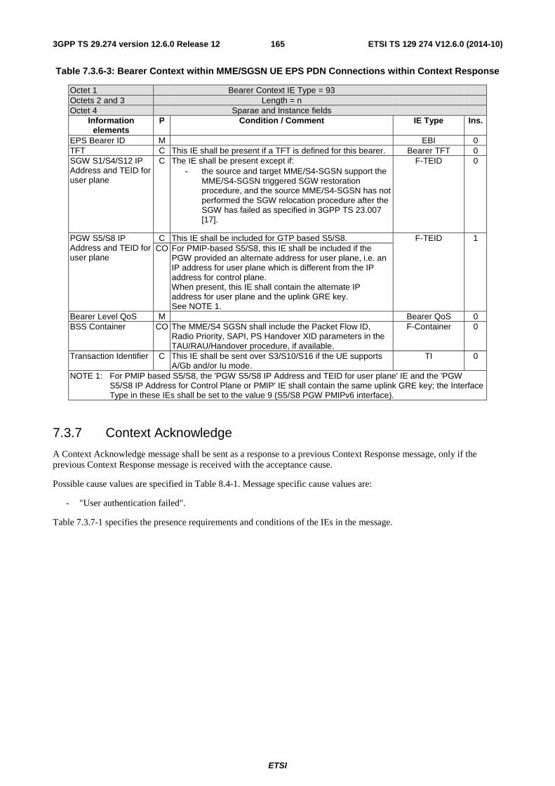
ETSI
ETSI TS 129 274 V12.6.0 (2014-10)1653GPP TS 29.274 version 12.6.0 Release 12
Table 7.3.6-3: Bearer Context within MME/SGSN UE EPS PDN Connections within Context Response
Octet 1 Bearer Context IE Type = 93 Octets 2 and 3 Length = n Octet 4 Sparae and Instance fields
Information elements
P Condition / Comment IE Type Ins.
EPS Bearer ID M EBI 0 TFT C This IE shall be present if a TFT is defined for this bearer. Bearer TFT 0 SGW S1/S4/S12 IP Address and TEID for user plane
C The IE shall be present except if: - the source and target MME/S4-SGSN support the
MME/S4-SGSN triggered SGW restoration procedure, and the source MME/S4-SGSN has not performed the SGW relocation procedure after the SGW has failed as specified in 3GPP TS 23.007 [17].
F-TEID 0
PGW S5/S8 IP Address and TEID for user plane
C This IE shall be included for GTP based S5/S8. F-TEID 1 CO For PMIP-based S5/S8, this IE shall be included if the
PGW provided an alternate address for user plane, i.e. an IP address for user plane which is different from the IP address for control plane. When present, this IE shall contain the alternate IP address for user plane and the uplink GRE key. See NOTE 1.
Bearer Level QoS M Bearer QoS 0 BSS Container CO The MME/S4 SGSN shall include the Packet Flow ID,
Radio Priority, SAPI, PS Handover XID parameters in the TAU/RAU/Handover procedure, if available.
F-Container 0
Transaction Identifier C This IE shall be sent over S3/S10/S16 if the UE supports A/Gb and/or Iu mode.
TI 0
NOTE 1: For PMIP based S5/S8, the 'PGW S5/S8 IP Address and TEID for user plane' IE and the 'PGW S5/S8 IP Address for Control Plane or PMIP' IE shall contain the same uplink GRE key; the Interface Type in these IEs shall be set to the value 9 (S5/S8 PGW PMIPv6 interface).
7.3.7 Context Acknowledge
A Context Acknowledge message shall be sent as a response to a previous Context Response message, only if the previous Context Response message is received with the acceptance cause.
Possible cause values are specified in Table 8.4-1. Message specific cause values are:
- "User authentication failed".
Table 7.3.7-1 specifies the presence requirements and conditions of the IEs in the message.
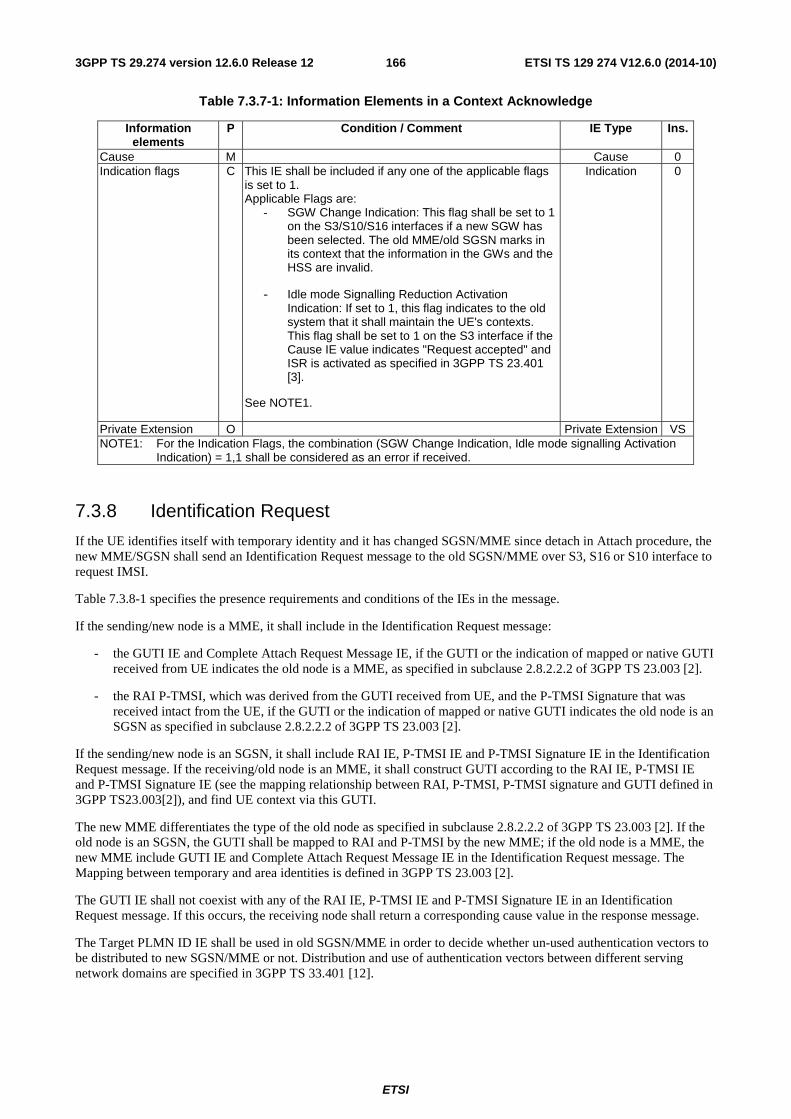
ETSI
ETSI TS 129 274 V12.6.0 (2014-10)1663GPP TS 29.274 version 12.6.0 Release 12
Table 7.3.7-1: Information Elements in a Context Acknowledge
Information elements
P Condition / Comment IE Type Ins.
Cause M Cause 0 Indication flags C This IE shall be included if any one of the applicable flags
is set to 1. Applicable Flags are:
- SGW Change Indication: This flag shall be set to 1 on the S3/S10/S16 interfaces if a new SGW has been selected. The old MME/old SGSN marks in its context that the information in the GWs and the HSS are invalid.
- Idle mode Signalling Reduction Activation Indication: If set to 1, this flag indicates to the old system that it shall maintain the UE's contexts. This flag shall be set to 1 on the S3 interface if the Cause IE value indicates "Request accepted" and ISR is activated as specified in 3GPP TS 23.401 [3].
See NOTE1.
Indication 0
Private Extension O Private Extension VS NOTE1: For the Indication Flags, the combination (SGW Change Indication, Idle mode signalling Activation
Indication) = 1,1 shall be considered as an error if received.
7.3.8 Identification Request
If the UE identifies itself with temporary identity and it has changed SGSN/MME since detach in Attach procedure, the new MME/SGSN shall send an Identification Request message to the old SGSN/MME over S3, S16 or S10 interface to request IMSI.
Table 7.3.8-1 specifies the presence requirements and conditions of the IEs in the message.
If the sending/new node is a MME, it shall include in the Identification Request message:
- the GUTI IE and Complete Attach Request Message IE, if the GUTI or the indication of mapped or native GUTI received from UE indicates the old node is a MME, as specified in subclause 2.8.2.2.2 of 3GPP TS 23.003 [2].
- the RAI P-TMSI, which was derived from the GUTI received from UE, and the P-TMSI Signature that was received intact from the UE, if the GUTI or the indication of mapped or native GUTI indicates the old node is an SGSN as specified in subclause 2.8.2.2.2 of 3GPP TS 23.003 [2].
If the sending/new node is an SGSN, it shall include RAI IE, P-TMSI IE and P-TMSI Signature IE in the Identification Request message. If the receiving/old node is an MME, it shall construct GUTI according to the RAI IE, P-TMSI IE and P-TMSI Signature IE (see the mapping relationship between RAI, P-TMSI, P-TMSI signature and GUTI defined in 3GPP TS23.003[2]), and find UE context via this GUTI.
The new MME differentiates the type of the old node as specified in subclause 2.8.2.2.2 of 3GPP TS 23.003 [2]. If the old node is an SGSN, the GUTI shall be mapped to RAI and P-TMSI by the new MME; if the old node is a MME, the new MME include GUTI IE and Complete Attach Request Message IE in the Identification Request message. The Mapping between temporary and area identities is defined in 3GPP TS 23.003 [2].
The GUTI IE shall not coexist with any of the RAI IE, P-TMSI IE and P-TMSI Signature IE in an Identification Request message. If this occurs, the receiving node shall return a corresponding cause value in the response message.
The Target PLMN ID IE shall be used in old SGSN/MME in order to decide whether un-used authentication vectors to be distributed to new SGSN/MME or not. Distribution and use of authentication vectors between different serving network domains are specified in 3GPP TS 33.401 [12].
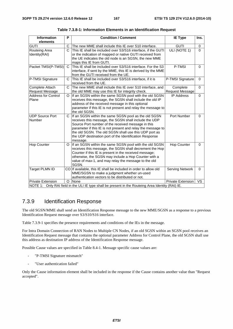
ETSI
ETSI TS 129 274 V12.6.0 (2014-10)1673GPP TS 29.274 version 12.6.0 Release 12
Table 7.3.8-1: Information Elements in an Identification Request
Information elements
P Condition / Comment IE Type Ins.
GUTI C The new MME shall include this IE over S10 interface. GUTI 0 Routeing Area Identity(RAI)
C This IE shall be included over S3/S16 interface, if the GUTI or the indication of mapped or native GUTI received from the UE indicates the old node is an SGSN, the new MME maps this IE from GUTI.
ULI (NOTE 1) 0
Packet TMSI(P-TMSI) C This IE shall be included over S3/S16 interface. For the S3 interface, if sent by the MME, this IE is derived by the MME from the GUTI received from the UE.
P-TMSI 0
P-TMSI Signature C This IE shall be included over S3/S16 interface, if it is received from the UE.
P-TMSI Signature 0
Complete Attach Request Message
C The new MME shall include this IE over S10 interface, and the old MME may use this IE for integrity check.
Complete Request Message
0
Address for Control Plane
O If an SGSN within the same SGSN pool with the old SGSN receives this message, the SGSN shall include the old IP address of the received message in this optional parameter if this IE is not present and relay the message to the old SGSN.
IP Address 0
UDP Source Port Number
C If an SGSN within the same SGSN pool as the old SGSN receives this message, the SGSN shall include the UDP Source Port number of the received message in this parameter if this IE is not present and relay the message to the old SGSN. The old SGSN shall use this UDP port as the UDP destination port of the Identification Response message.
Port Number 0
Hop Counter O If an SGSN within the same SGSN pool with the old SGSN receives this message, the SGSN shall decrement the Hop Counter if this IE is present in the received message; otherwise, the SGSN may include a Hop Counter with a value of max-1, and may relay the message to the old SGSN.
Hop Counter 0
Target PLMN ID CO If available, this IE shall be included in order to allow old MME/SGSN to make a judgment whether un-used authentication vectors to be distributed or not.
Serving Network 0
Private Extension O None Private Extension VS NOTE 1: Only RAI field in the ULI IE type shall be present in the Routeing Area Identity (RAI) IE.
7.3.9 Identification Response
The old SGSN/MME shall send an Identification Response message to the new MME/SGSN as a response to a previous Identification Request message over S3/S10/S16 interface.
Table 7.3.9-1 specifies the presence requirements and conditions of the IEs in the message.
For Intra Domain Connection of RAN Nodes to Multiple CN Nodes, if an old SGSN within an SGSN pool receives an Identification Request message that contains the optional parameter Address for Control Plane, the old SGSN shall use this address as destination IP address of the Identification Response message.
Possible Cause values are specified in Table 8.4-1. Message specific cause values are:
- "P-TMSI Signature mismatch"
- "User authentication failed"
Only the Cause information element shall be included in the response if the Cause contains another value than "Request accepted".
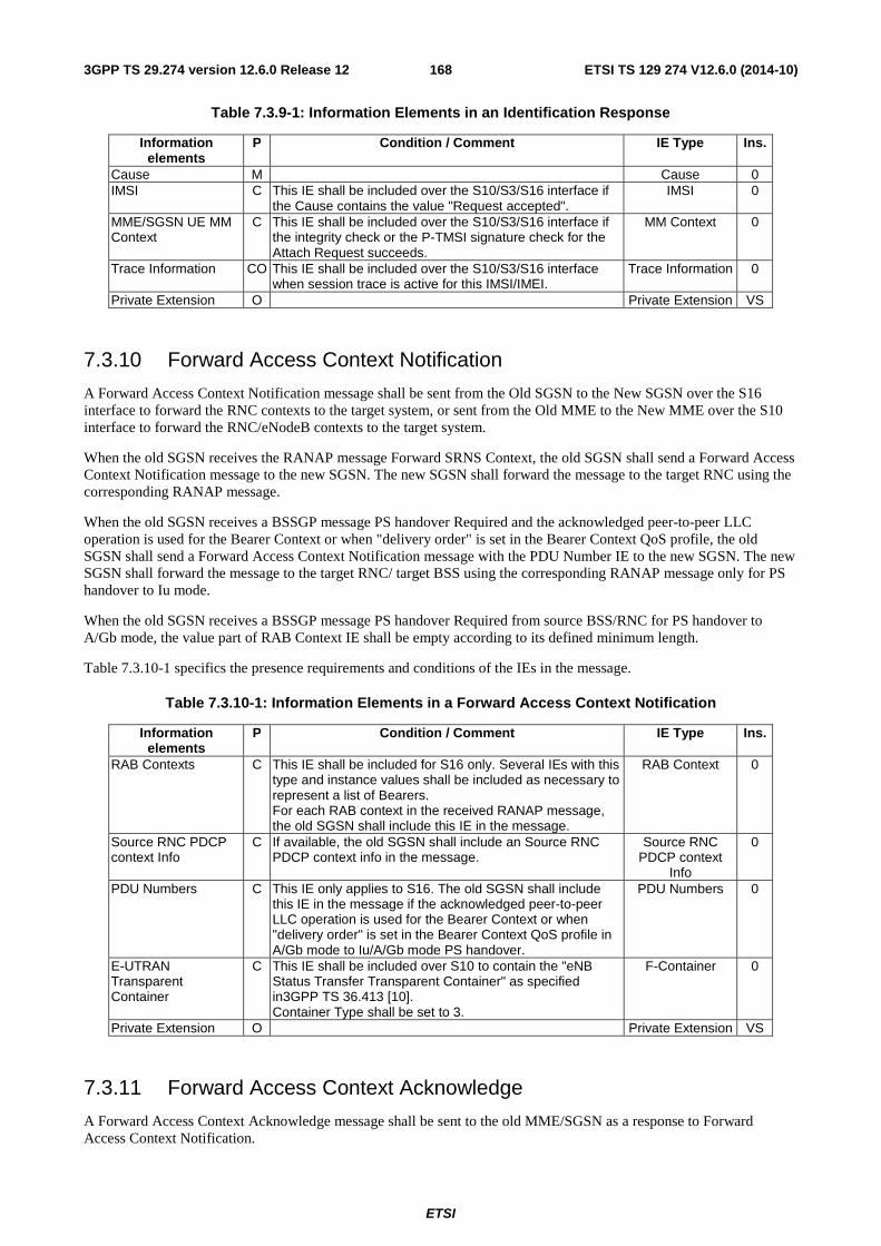
ETSI
ETSI TS 129 274 V12.6.0 (2014-10)1683GPP TS 29.274 version 12.6.0 Release 12
Table 7.3.9-1: Information Elements in an Identification Response
Information elements
P Condition / Comment IE Type Ins.
Cause M Cause 0 IMSI C This IE shall be included over the S10/S3/S16 interface if
the Cause contains the value "Request accepted". IMSI 0
MME/SGSN UE MM Context
C This IE shall be included over the S10/S3/S16 interface if the integrity check or the P-TMSI signature check for the Attach Request succeeds.
MM Context 0
Trace Information CO This IE shall be included over the S10/S3/S16 interface when session trace is active for this IMSI/IMEI.
Trace Information 0
Private Extension O Private Extension VS
7.3.10 Forward Access Context Notification
A Forward Access Context Notification message shall be sent from the Old SGSN to the New SGSN over the S16 interface to forward the RNC contexts to the target system, or sent from the Old MME to the New MME over the S10 interface to forward the RNC/eNodeB contexts to the target system.
When the old SGSN receives the RANAP message Forward SRNS Context, the old SGSN shall send a Forward Access Context Notification message to the new SGSN. The new SGSN shall forward the message to the target RNC using the corresponding RANAP message.
When the old SGSN receives a BSSGP message PS handover Required and the acknowledged peer-to-peer LLC operation is used for the Bearer Context or when "delivery order" is set in the Bearer Context QoS profile, the old SGSN shall send a Forward Access Context Notification message with the PDU Number IE to the new SGSN. The new SGSN shall forward the message to the target RNC/ target BSS using the corresponding RANAP message only for PS handover to Iu mode.
When the old SGSN receives a BSSGP message PS handover Required from source BSS/RNC for PS handover to A/Gb mode, the value part of RAB Context IE shall be empty according to its defined minimum length.
Table 7.3.10-1 specifics the presence requirements and conditions of the IEs in the message.
Table 7.3.10-1: Information Elements in a Forward Access Context Notification
Information elements
P Condition / Comment IE Type Ins.
RAB Contexts C This IE shall be included for S16 only. Several IEs with this type and instance values shall be included as necessary to represent a list of Bearers. For each RAB context in the received RANAP message, the old SGSN shall include this IE in the message.
RAB Context 0
Source RNC PDCP context Info
C If available, the old SGSN shall include an Source RNC PDCP context info in the message.
Source RNC PDCP context
Info
0
PDU Numbers C This IE only applies to S16. The old SGSN shall include this IE in the message if the acknowledged peer-to-peer LLC operation is used for the Bearer Context or when "delivery order" is set in the Bearer Context QoS profile in A/Gb mode to Iu/A/Gb mode PS handover.
PDU Numbers 0
E-UTRAN Transparent Container
C This IE shall be included over S10 to contain the "eNB Status Transfer Transparent Container" as specified in3GPP TS 36.413 [10]. Container Type shall be set to 3.
F-Container 0
Private Extension O Private Extension VS
7.3.11 Forward Access Context Acknowledge
A Forward Access Context Acknowledge message shall be sent to the old MME/SGSN as a response to Forward Access Context Notification.
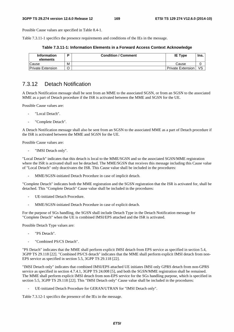
ETSI
ETSI TS 129 274 V12.6.0 (2014-10)1693GPP TS 29.274 version 12.6.0 Release 12
Possible Cause values are specified in Table 8.4-1.
Table 7.3.11-1 specifics the presence requirements and conditions of the IEs in the message.
Table 7.3.11-1: Information Elements in a Forward Access Context Acknowledge
Information elements
P Condition / Comment IE Type Ins.
Cause M Cause 0 Private Extension O Private Extension VS
7.3.12 Detach Notification
A Detach Notification message shall be sent from an MME to the associated SGSN, or from an SGSN to the associated MME as a part of Detach procedure if the ISR is activated between the MME and SGSN for the UE.
Possible Cause values are:
- "Local Detach".
- "Complete Detach".
A Detach Notification message shall also be sent from an SGSN to the associated MME as a part of Detach procedure if the ISR is activated between the MME and SGSN for the UE.
Possible Cause values are:
- "IMSI Detach only".
"Local Detach" indicates that this detach is local to the MME/SGSN and so the associated SGSN/MME registration where the ISR is activated shall not be detached. The MME/SGSN that receives this message including this Cause value of "Local Detach" only deactivates the ISR. This Cause value shall be included in the procedures:
- MME/SGSN-initiated Detach Procedure in case of implicit detach.
"Complete Detach" indicates both the MME registration and the SGSN registration that the ISR is activated for, shall be detached. This "Complete Detach" Cause value shall be included in the procedures:
- UE-initiated Detach Procedure.
- MME/SGSN-initiated Detach Procedure in case of explicit detach.
For the purpose of SGs handling, the SGSN shall include Detach Type in the Detach Notification message for "Complete Detach" when the UE is combined IMSI/EPS attached and the ISR is activated.
Possible Detach Type values are:
- "PS Detach".
- "Combined PS/CS Detach".
"PS Detach" indicates that the MME shall perform explicit IMSI detach from EPS service as specified in section 5.4, 3GPP TS 29.118 [22]. "Combined PS/CS detach" indicates that the MME shall perform explicit IMSI detach from non-EPS service as specified in section 5.5, 3GPP TS 29.118 [22].
"IMSI Detach only" indicates that combined IMSI/EPS attached UE initiates IMSI only GPRS detach from non-GPRS service as specified in section 4.7.4.1, 3GPP TS 24.008 [5], and both the SGSN/MME registration shall be remained. The MME shall perform explicit IMSI detach from non-EPS service for the SGs handling purpose, which is specified in section 5.5, 3GPP TS 29.118 [22]. This "IMSI Detach only" Cause value shall be included in the procedures:
- UE-initiated Detach Procedure for GERAN/UTRAN for "IMSI Detach only".
Table 7.3.12-1 specifics the presence of the IEs in the message.
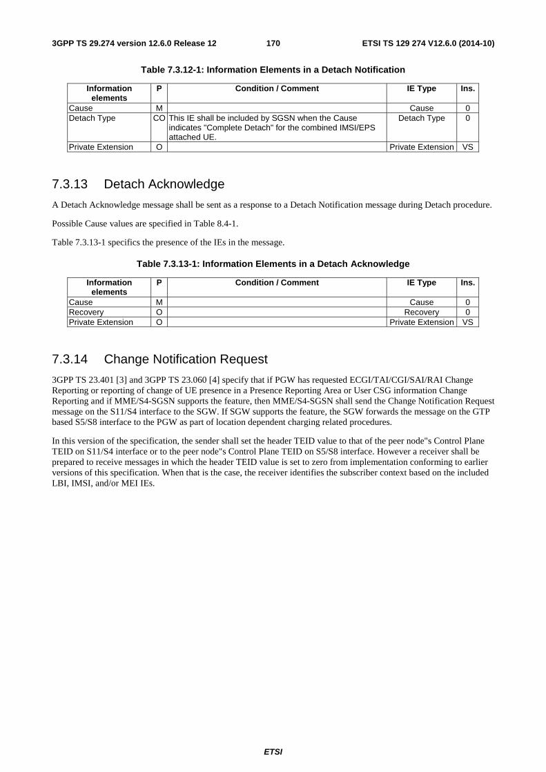
ETSI
ETSI TS 129 274 V12.6.0 (2014-10)1703GPP TS 29.274 version 12.6.0 Release 12
Table 7.3.12-1: Information Elements in a Detach Notification
Information elements
P Condition / Comment IE Type Ins.
Cause M Cause 0 Detach Type CO This IE shall be included by SGSN when the Cause
indicates "Complete Detach" for the combined IMSI/EPS attached UE.
Detach Type 0
Private Extension O Private Extension VS
7.3.13 Detach Acknowledge
A Detach Acknowledge message shall be sent as a response to a Detach Notification message during Detach procedure.
Possible Cause values are specified in Table 8.4-1.
Table 7.3.13-1 specifics the presence of the IEs in the message.
Table 7.3.13-1: Information Elements in a Detach Acknowledge
Information elements
P Condition / Comment IE Type Ins.
Cause M Cause 0 Recovery O Recovery 0 Private Extension O Private Extension VS
7.3.14 Change Notification Request
3GPP TS 23.401 [3] and 3GPP TS 23.060 [4] specify that if PGW has requested ECGI/TAI/CGI/SAI/RAI Change Reporting or reporting of change of UE presence in a Presence Reporting Area or User CSG information Change Reporting and if MME/S4-SGSN supports the feature, then MME/S4-SGSN shall send the Change Notification Request message on the S11/S4 interface to the SGW. If SGW supports the feature, the SGW forwards the message on the GTP based S5/S8 interface to the PGW as part of location dependent charging related procedures.
In this version of the specification, the sender shall set the header TEID value to that of the peer node"s Control Plane TEID on S11/S4 interface or to the peer node"s Control Plane TEID on S5/S8 interface. However a receiver shall be prepared to receive messages in which the header TEID value is set to zero from implementation conforming to earlier versions of this specification. When that is the case, the receiver identifies the subscriber context based on the included LBI, IMSI, and/or MEI IEs.
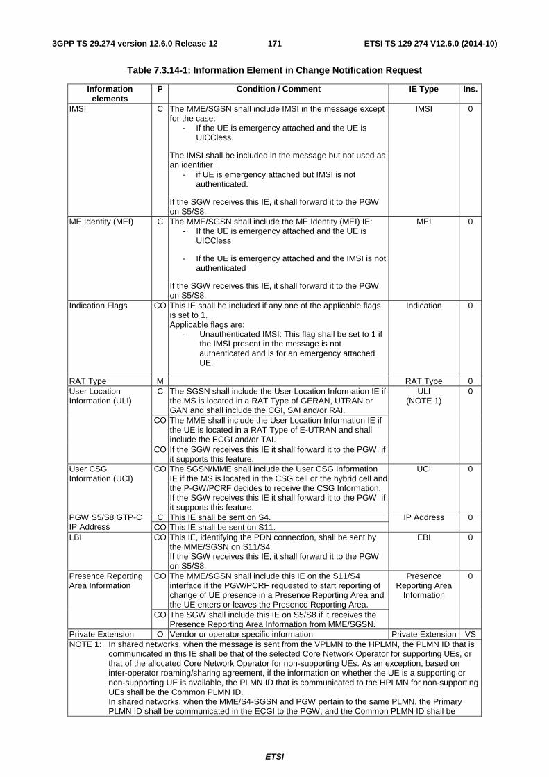
ETSI
ETSI TS 129 274 V12.6.0 (2014-10)1713GPP TS 29.274 version 12.6.0 Release 12
Table 7.3.14-1: Information Element in Change Notification Request
Information elements
P Condition / Comment IE Type Ins.
IMSI C The MME/SGSN shall include IMSI in the message except for the case:
- If the UE is emergency attached and the UE is UICCless.
The IMSI shall be included in the message but not used as an identifier
- if UE is emergency attached but IMSI is not authenticated.
If the SGW receives this IE, it shall forward it to the PGW on S5/S8.
IMSI 0
ME Identity (MEI) C The MME/SGSN shall include the ME Identity (MEI) IE: - If the UE is emergency attached and the UE is
UICCless
- If the UE is emergency attached and the IMSI is not authenticated
If the SGW receives this IE, it shall forward it to the PGW on S5/S8.
MEI 0
Indication Flags CO This IE shall be included if any one of the applicable flags is set to 1. Applicable flags are:
- Unauthenticated IMSI: This flag shall be set to 1 if the IMSI present in the message is not authenticated and is for an emergency attached UE.
Indication 0
RAT Type M RAT Type 0 User Location Information (ULI)
C The SGSN shall include the User Location Information IE if the MS is located in a RAT Type of GERAN, UTRAN or GAN and shall include the CGI, SAI and/or RAI.
ULI (NOTE 1)
0
CO The MME shall include the User Location Information IE if the UE is located in a RAT Type of E-UTRAN and shall include the ECGI and/or TAI.
CO If the SGW receives this IE it shall forward it to the PGW, if it supports this feature.
User CSG Information (UCI)
CO The SGSN/MME shall include the User CSG Information IE if the MS is located in the CSG cell or the hybrid cell and the P-GW/PCRF decides to receive the CSG Information. If the SGW receives this IE it shall forward it to the PGW, if it supports this feature.
UCI 0
PGW S5/S8 GTP-C IP Address
C This IE shall be sent on S4. IP Address 0 CO This IE shall be sent on S11.
LBI CO This IE, identifying the PDN connection, shall be sent by the MME/SGSN on S11/S4. If the SGW receives this IE, it shall forward it to the PGW on S5/S8.
EBI 0
Presence Reporting Area Information
CO The MME/SGSN shall include this IE on the S11/S4 interface if the PGW/PCRF requested to start reporting of change of UE presence in a Presence Reporting Area and the UE enters or leaves the Presence Reporting Area.
Presence Reporting Area
Information
0
CO The SGW shall include this IE on S5/S8 if it receives the Presence Reporting Area Information from MME/SGSN.
Private Extension O Vendor or operator specific information Private Extension VS NOTE 1: In shared networks, when the message is sent from the VPLMN to the HPLMN, the PLMN ID that is
communicated in this IE shall be that of the selected Core Network Operator for supporting UEs, or that of the allocated Core Network Operator for non-supporting UEs. As an exception, based on inter-operator roaming/sharing agreement, if the information on whether the UE is a supporting or non-supporting UE is available, the PLMN ID that is communicated to the HPLMN for non-supporting UEs shall be the Common PLMN ID. In shared networks, when the MME/S4-SGSN and PGW pertain to the same PLMN, the Primary PLMN ID shall be communicated in the ECGI to the PGW, and the Common PLMN ID shall be
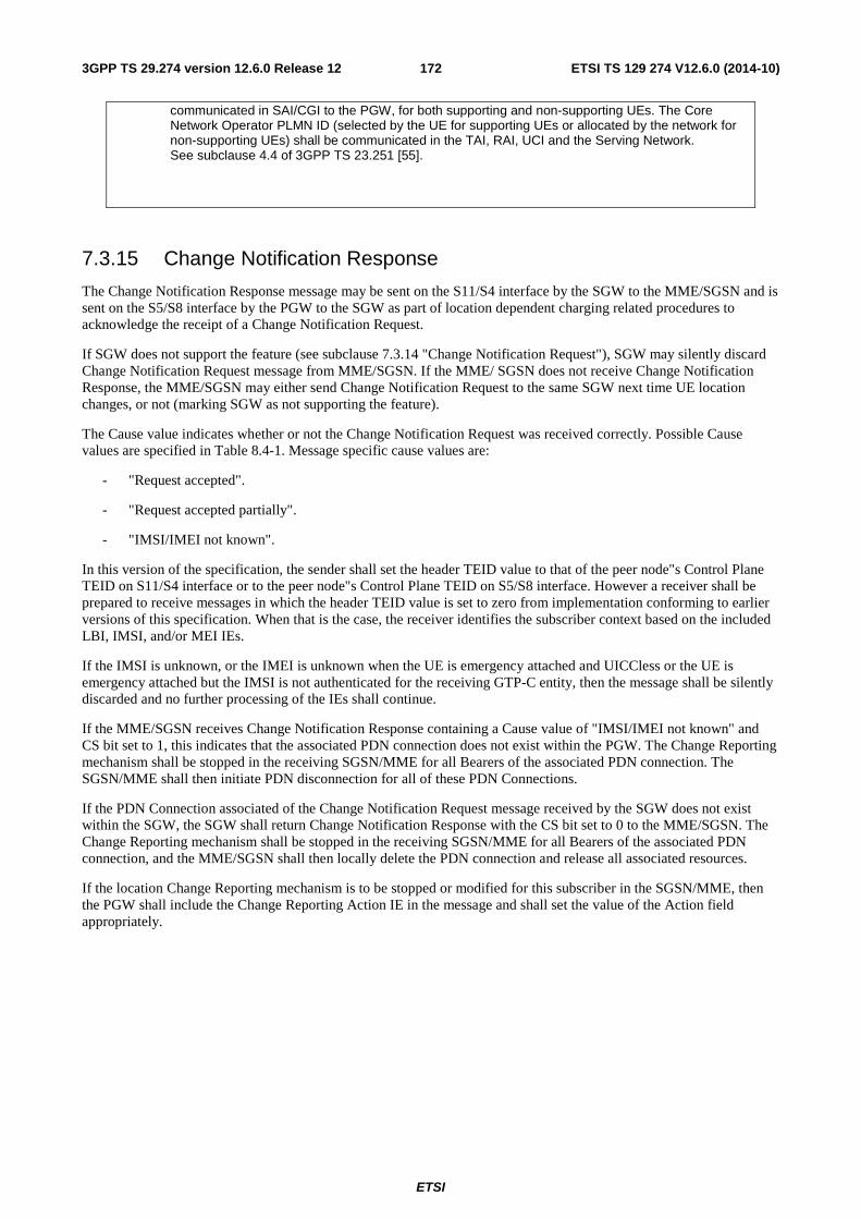
ETSI
ETSI TS 129 274 V12.6.0 (2014-10)1723GPP TS 29.274 version 12.6.0 Release 12
communicated in SAI/CGI to the PGW, for both supporting and non-supporting UEs. The Core Network Operator PLMN ID (selected by the UE for supporting UEs or allocated by the network for non-supporting UEs) shall be communicated in the TAI, RAI, UCI and the Serving Network. See subclause 4.4 of 3GPP TS 23.251 [55].
7.3.15 Change Notification Response
The Change Notification Response message may be sent on the S11/S4 interface by the SGW to the MME/SGSN and is sent on the S5/S8 interface by the PGW to the SGW as part of location dependent charging related procedures to acknowledge the receipt of a Change Notification Request.
If SGW does not support the feature (see subclause 7.3.14 "Change Notification Request"), SGW may silently discard Change Notification Request message from MME/SGSN. If the MME/ SGSN does not receive Change Notification Response, the MME/SGSN may either send Change Notification Request to the same SGW next time UE location changes, or not (marking SGW as not supporting the feature).
The Cause value indicates whether or not the Change Notification Request was received correctly. Possible Cause values are specified in Table 8.4-1. Message specific cause values are:
- "Request accepted".
- "Request accepted partially".
- "IMSI/IMEI not known".
In this version of the specification, the sender shall set the header TEID value to that of the peer node"s Control Plane TEID on S11/S4 interface or to the peer node"s Control Plane TEID on S5/S8 interface. However a receiver shall be prepared to receive messages in which the header TEID value is set to zero from implementation conforming to earlier versions of this specification. When that is the case, the receiver identifies the subscriber context based on the included LBI, IMSI, and/or MEI IEs.
If the IMSI is unknown, or the IMEI is unknown when the UE is emergency attached and UICCless or the UE is emergency attached but the IMSI is not authenticated for the receiving GTP-C entity, then the message shall be silently discarded and no further processing of the IEs shall continue.
If the MME/SGSN receives Change Notification Response containing a Cause value of "IMSI/IMEI not known" and CS bit set to 1, this indicates that the associated PDN connection does not exist within the PGW. The Change Reporting mechanism shall be stopped in the receiving SGSN/MME for all Bearers of the associated PDN connection. The SGSN/MME shall then initiate PDN disconnection for all of these PDN Connections.
If the PDN Connection associated of the Change Notification Request message received by the SGW does not exist within the SGW, the SGW shall return Change Notification Response with the CS bit set to 0 to the MME/SGSN. The Change Reporting mechanism shall be stopped in the receiving SGSN/MME for all Bearers of the associated PDN connection, and the MME/SGSN shall then locally delete the PDN connection and release all associated resources.
If the location Change Reporting mechanism is to be stopped or modified for this subscriber in the SGSN/MME, then the PGW shall include the Change Reporting Action IE in the message and shall set the value of the Action field appropriately.
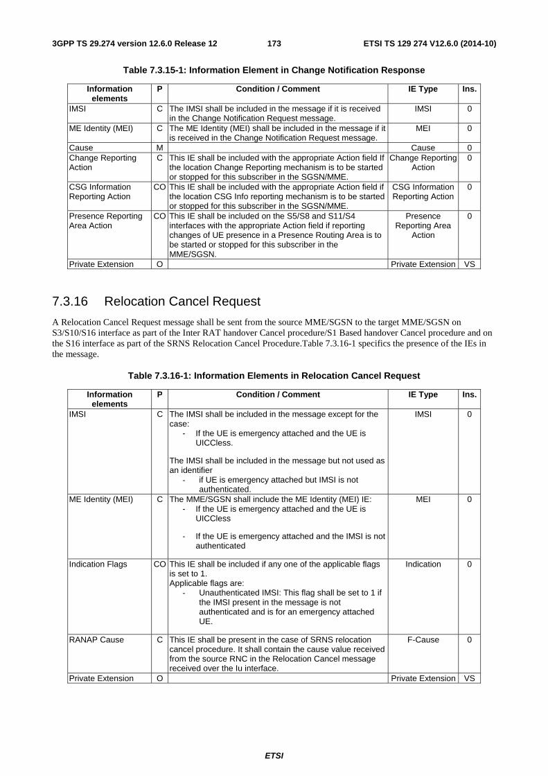
ETSI
ETSI TS 129 274 V12.6.0 (2014-10)1733GPP TS 29.274 version 12.6.0 Release 12
Table 7.3.15-1: Information Element in Change Notification Response
Information elements
P Condition / Comment IE Type Ins.
IMSI C The IMSI shall be included in the message if it is received in the Change Notification Request message.
IMSI 0
ME Identity (MEI) C The ME Identity (MEI) shall be included in the message if it is received in the Change Notification Request message.
MEI 0
Cause M Cause 0 Change Reporting Action
C This IE shall be included with the appropriate Action field If the location Change Reporting mechanism is to be started or stopped for this subscriber in the SGSN/MME.
Change Reporting Action
0
CSG Information Reporting Action
CO This IE shall be included with the appropriate Action field if the location CSG Info reporting mechanism is to be started or stopped for this subscriber in the SGSN/MME.
CSG Information Reporting Action
0
Presence Reporting Area Action
CO This IE shall be included on the S5/S8 and S11/S4 interfaces with the appropriate Action field if reporting changes of UE presence in a Presence Routing Area is to be started or stopped for this subscriber in the MME/SGSN.
Presence Reporting Area
Action
0
Private Extension O Private Extension VS
7.3.16 Relocation Cancel Request
A Relocation Cancel Request message shall be sent from the source MME/SGSN to the target MME/SGSN on S3/S10/S16 interface as part of the Inter RAT handover Cancel procedure/S1 Based handover Cancel procedure and on the S16 interface as part of the SRNS Relocation Cancel Procedure.Table 7.3.16-1 specifics the presence of the IEs in the message.
Table 7.3.16-1: Information Elements in Relocation Cancel Request
Information elements
P Condition / Comment IE Type Ins.
IMSI C The IMSI shall be included in the message except for the case:
- If the UE is emergency attached and the UE is UICCless.
The IMSI shall be included in the message but not used as an identifier
- if UE is emergency attached but IMSI is not authenticated.
IMSI 0
ME Identity (MEI) C The MME/SGSN shall include the ME Identity (MEI) IE: - If the UE is emergency attached and the UE is
UICCless
- If the UE is emergency attached and the IMSI is not authenticated
MEI 0
Indication Flags CO This IE shall be included if any one of the applicable flags is set to 1. Applicable flags are:
- Unauthenticated IMSI: This flag shall be set to 1 if the IMSI present in the message is not authenticated and is for an emergency attached UE.
Indication 0
RANAP Cause C This IE shall be present in the case of SRNS relocation cancel procedure. It shall contain the cause value received from the source RNC in the Relocation Cancel message received over the Iu interface.
F-Cause 0
Private Extension O Private Extension VS
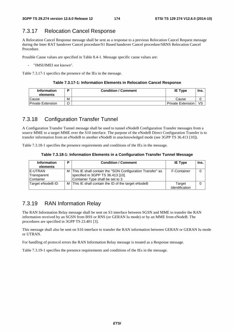
ETSI
ETSI TS 129 274 V12.6.0 (2014-10)1743GPP TS 29.274 version 12.6.0 Release 12
7.3.17 Relocation Cancel Response
A Relocation Cancel Response message shall be sent as a response to a previous Relocation Cancel Request message during the Inter RAT handover Cancel procedure/S1 Based handover Cancel procedure/SRNS Relocation Cancel Procedure.
Possible Cause values are specified in Table 8.4-1. Message specific cause values are:
- "IMSI/IMEI not known".
Table 7.3.17-1 specifics the presence of the IEs in the message.
Table 7.3.17-1: Information Elements in Relocation Cancel Response
Information elements
P Condition / Comment IE Type Ins.
Cause M Cause 0 Private Extension O Private Extension VS
7.3.18 Configuration Transfer Tunnel
A Configuration Transfer Tunnel message shall be used to tunnel eNodeB Configuration Transfer messages from a source MME to a target MME over the S10 interface. The purpose of the eNodeB Direct Configuration Transfer is to transfer information from an eNodeB to another eNodeB in unacknowledged mode (see 3GPP TS 36.413 [10]).
Table 7.3.18-1 specifies the presence requirements and conditions of the IEs in the message.
Table 7.3.18-1: Information Elements in a Configuration Transfer Tunnel Message
Information elements
P Condition / Comment IE Type Ins.
E-UTRAN Transparent Container
M This IE shall contain the "SON Configuration Transfer" as specified in 3GPP TS 36.413 [10]. Container Type shall be set to 3.
F-Container 0
Target eNodeB ID M This IE shall contain the ID of the target eNodeB Target Identification
0
7.3.19 RAN Information Relay
The RAN Information Relay message shall be sent on S3 interface between SGSN and MME to transfer the RAN information received by an SGSN from BSS or RNS (or GERAN Iu mode) or by an MME from eNodeB. The procedures are specified in 3GPP TS 23.401 [3].
This message shall also be sent on S16 interface to transfer the RAN information between GERAN or GERAN Iu mode or UTRAN.
For handling of protocol errors the RAN Information Relay message is treated as a Response message.
Table 7.3.19-1 specifies the presence requirements and conditions of the IEs in the message.
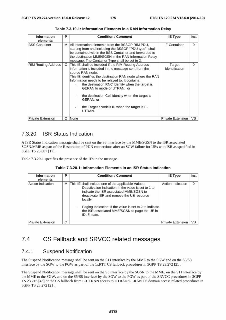
ETSI
ETSI TS 129 274 V12.6.0 (2014-10)1753GPP TS 29.274 version 12.6.0 Release 12
Table 7.3.19-1: Information Elements in a RAN Information Relay
Information elements
P Condition / Comment IE Type Ins.
BSS Container M All information elements from the BSSGP RIM PDU, starting from and including the BSSGP "PDU type", shall be contained within the BSS Container and forwarded to the destination MME/SGSN in the RAN Information Relay message. The Container Type shall be set to 2.
F-Container 0
RIM Routing Address C This IE shall be included if the RIM Routing Address information is included in the message sent from the source RAN node. This IE identifies the destination RAN node where the RAN Information needs to be relayed to. It contains:
- the destination RNC Identity when the target is GERAN Iu mode or UTRAN; or
- the destination Cell Identity when the target is GERAN; or
- the Target eNodeB ID when the target is E-UTRAN.
Target Identification
0
Private Extension O None Private Extension VS
7.3.20 ISR Status Indication
A ISR Status Indication message shall be sent on the S3 interface by the MME/SGSN to the ISR associated SGSN/MME as part of the Restoration of PDN connections after an SGW failure for UEs with ISR as specified in 3GPP TS 23.007 [17].
Table 7.3.20-1 specifies the presence of the IEs in the message.
Table 7.3.20-1: Information Elements in an ISR Status Indication
Information elements
P Condition / Comment IE Type Ins.
Action Indication M This IE shall include one of the applicable Values: - Deactivation Indication: If the value is set to 1 to
indicate the ISR associated MME/SGSN to deactivate ISR and remove the UE resource locally.
- Paging Indication: If the value is set to 2 to indicate the ISR associated MME/SGSN to page the UE in IDLE state.
Action Indication 0
Private Extension O Private Extension VS
7.4 CS Fallback and SRVCC related messages
7.4.1 Suspend Notification
The Suspend Notification message shall be sent on the S11 interface by the MME to the SGW and on the S5/S8 interface by the SGW to the PGW as part of the 1xRTT CS fallback procedures in 3GPP TS 23.272 [21].
The Suspend Notification message shall be sent on the S3 interface by the SGSN to the MME, on the S11 interface by the MME to the SGW, and on the S5/S8 interface by the SGW to the PGW as part of the SRVCC procedures in 3GPP TS 23.216 [43] or the CS fallback from E-UTRAN access to UTRAN/GERAN CS domain access related procedures in 3GPP TS 23.272 [21].
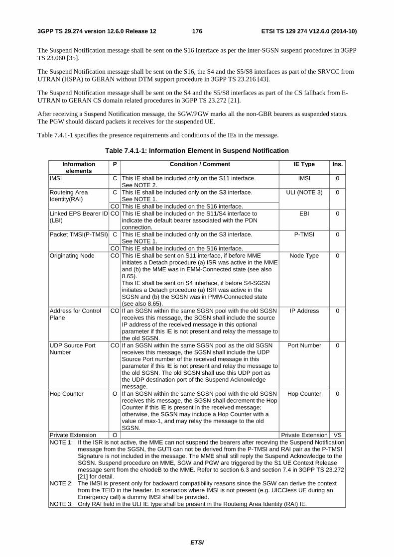
ETSI
ETSI TS 129 274 V12.6.0 (2014-10)1763GPP TS 29.274 version 12.6.0 Release 12
The Suspend Notification message shall be sent on the S16 interface as per the inter-SGSN suspend procedures in 3GPP TS 23.060 [35].
The Suspend Notification message shall be sent on the S16, the S4 and the S5/S8 interfaces as part of the SRVCC from UTRAN (HSPA) to GERAN without DTM support procedure in 3GPP TS 23.216 [43].
The Suspend Notification message shall be sent on the S4 and the S5/S8 interfaces as part of the CS fallback from E-UTRAN to GERAN CS domain related procedures in 3GPP TS 23.272 [21].
After receiving a Suspend Notification message, the SGW/PGW marks all the non-GBR bearers as suspended status. The PGW should discard packets it receives for the suspended UE.
Table 7.4.1-1 specifies the presence requirements and conditions of the IEs in the message.
Table 7.4.1-1: Information Element in Suspend Notification
Information elements
P Condition / Comment IE Type Ins.
IMSI C This IE shall be included only on the S11 interface. See NOTE 2.
IMSI 0
Routeing Area Identity(RAI)
C This IE shall be included only on the S3 interface. See NOTE 1.
ULI (NOTE 3) 0
CO This IE shall be included on the S16 interface. Linked EPS Bearer ID (LBI)
CO This IE shall be included on the S11/S4 interface to indicate the default bearer associated with the PDN connection.
EBI 0
Packet TMSI(P-TMSI) C This IE shall be included only on the S3 interface. See NOTE 1.
P-TMSI 0
CO This IE shall be included on the S16 interface. Originating Node CO This IE shall be sent on S11 interface, if before MME
initiates a Detach procedure (a) ISR was active in the MME and (b) the MME was in EMM-Connected state (see also 8.65). This IE shall be sent on S4 interface, if before S4-SGSN initiates a Detach procedure (a) ISR was active in the SGSN and (b) the SGSN was in PMM-Connected state (see also 8.65).
Node Type 0
Address for Control Plane
CO If an SGSN within the same SGSN pool with the old SGSN receives this message, the SGSN shall include the source IP address of the received message in this optional parameter if this IE is not present and relay the message to the old SGSN.
IP Address 0
UDP Source Port Number
CO If an SGSN within the same SGSN pool as the old SGSN receives this message, the SGSN shall include the UDP Source Port number of the received message in this parameter if this IE is not present and relay the message to the old SGSN. The old SGSN shall use this UDP port as the UDP destination port of the Suspend Acknowledge message.
Port Number 0
Hop Counter O If an SGSN within the same SGSN pool with the old SGSN receives this message, the SGSN shall decrement the Hop Counter if this IE is present in the received message; otherwise, the SGSN may include a Hop Counter with a value of max-1, and may relay the message to the old SGSN.
Hop Counter 0
Private Extension O Private Extension VS NOTE 1: If the ISR is not active, the MME can not suspend the bearers after receving the Suspend Notification
message from the SGSN, the GUTI can not be derived from the P-TMSI and RAI pair as the P-TMSI Signature is not included in the message. The MME shall still reply the Suspend Acknowledge to the SGSN. Suspend procedure on MME, SGW and PGW are triggered by the S1 UE Context Release message sent from the eNodeB to the MME. Refer to section 6.3 and section 7.4 in 3GPP TS 23.272 [21] for detail.
NOTE 2: The IMSI is present only for backward compatibility reasons since the SGW can derive the context from the TEID in the header. In scenarios where IMSI is not present (e.g. UICCless UE during an Emergency call) a dummy IMSI shall be provided.
NOTE 3: Only RAI field in the ULI IE type shall be present in the Routeing Area Identity (RAI) IE.
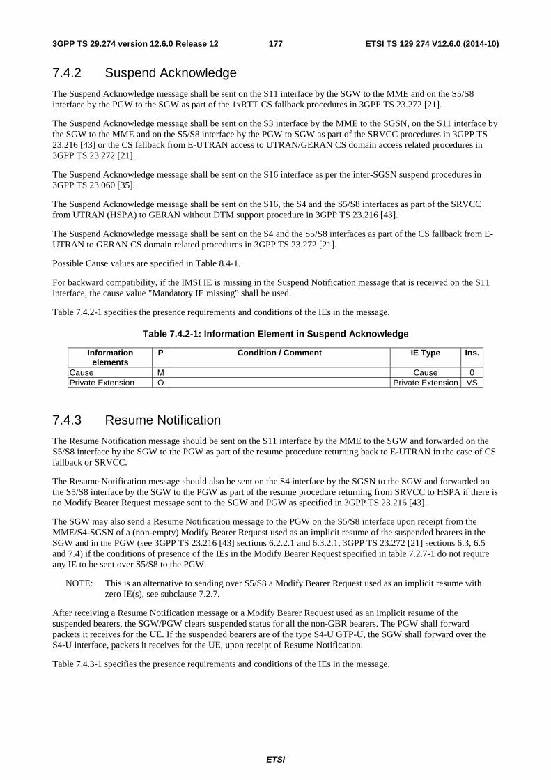
ETSI
ETSI TS 129 274 V12.6.0 (2014-10)1773GPP TS 29.274 version 12.6.0 Release 12
7.4.2 Suspend Acknowledge
The Suspend Acknowledge message shall be sent on the S11 interface by the SGW to the MME and on the S5/S8 interface by the PGW to the SGW as part of the 1xRTT CS fallback procedures in 3GPP TS 23.272 [21].
The Suspend Acknowledge message shall be sent on the S3 interface by the MME to the SGSN, on the S11 interface by the SGW to the MME and on the S5/S8 interface by the PGW to SGW as part of the SRVCC procedures in 3GPP TS 23.216 [43] or the CS fallback from E-UTRAN access to UTRAN/GERAN CS domain access related procedures in 3GPP TS 23.272 [21].
The Suspend Acknowledge message shall be sent on the S16 interface as per the inter-SGSN suspend procedures in 3GPP TS 23.060 [35].
The Suspend Acknowledge message shall be sent on the S16, the S4 and the S5/S8 interfaces as part of the SRVCC from UTRAN (HSPA) to GERAN without DTM support procedure in 3GPP TS 23.216 [43].
The Suspend Acknowledge message shall be sent on the S4 and the S5/S8 interfaces as part of the CS fallback from E-UTRAN to GERAN CS domain related procedures in 3GPP TS 23.272 [21].
Possible Cause values are specified in Table 8.4-1.
For backward compatibility, if the IMSI IE is missing in the Suspend Notification message that is received on the S11 interface, the cause value "Mandatory IE missing" shall be used.
Table 7.4.2-1 specifies the presence requirements and conditions of the IEs in the message.
Table 7.4.2-1: Information Element in Suspend Acknowledge
Information elements
P Condition / Comment IE Type Ins.
Cause M Cause 0 Private Extension O Private Extension VS
7.4.3 Resume Notification
The Resume Notification message should be sent on the S11 interface by the MME to the SGW and forwarded on the S5/S8 interface by the SGW to the PGW as part of the resume procedure returning back to E-UTRAN in the case of CS fallback or SRVCC.
The Resume Notification message should also be sent on the S4 interface by the SGSN to the SGW and forwarded on the S5/S8 interface by the SGW to the PGW as part of the resume procedure returning from SRVCC to HSPA if there is no Modify Bearer Request message sent to the SGW and PGW as specified in 3GPP TS 23.216 [43].
The SGW may also send a Resume Notification message to the PGW on the S5/S8 interface upon receipt from the MME/S4-SGSN of a (non-empty) Modify Bearer Request used as an implicit resume of the suspended bearers in the SGW and in the PGW (see 3GPP TS 23.216 [43] sections 6.2.2.1 and 6.3.2.1, 3GPP TS 23.272 [21] sections 6.3, 6.5 and 7.4) if the conditions of presence of the IEs in the Modify Bearer Request specified in table 7.2.7-1 do not require any IE to be sent over S5/S8 to the PGW.
NOTE: This is an alternative to sending over S5/S8 a Modify Bearer Request used as an implicit resume with zero IE(s), see subclause 7.2.7.
After receiving a Resume Notification message or a Modify Bearer Request used as an implicit resume of the suspended bearers, the SGW/PGW clears suspended status for all the non-GBR bearers. The PGW shall forward packets it receives for the UE. If the suspended bearers are of the type S4-U GTP-U, the SGW shall forward over the S4-U interface, packets it receives for the UE, upon receipt of Resume Notification.
Table 7.4.3-1 specifies the presence requirements and conditions of the IEs in the message.
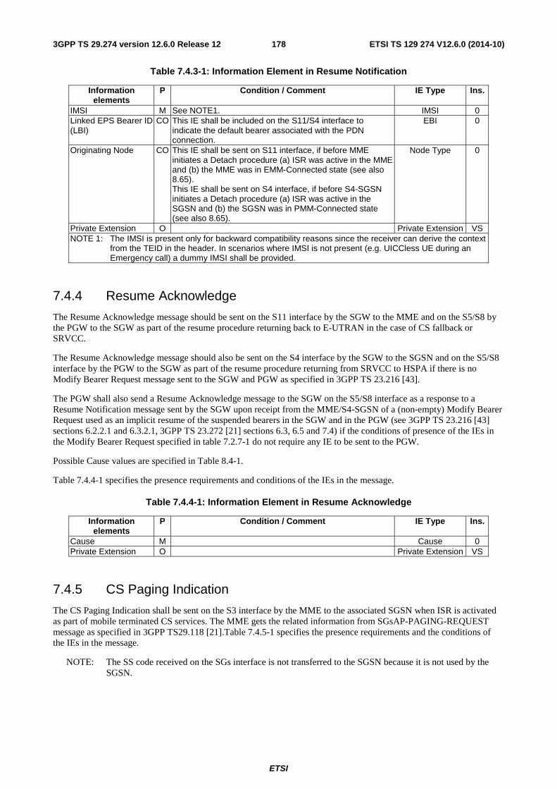
ETSI
ETSI TS 129 274 V12.6.0 (2014-10)1783GPP TS 29.274 version 12.6.0 Release 12
Table 7.4.3-1: Information Element in Resume Notification
Information elements
P Condition / Comment IE Type Ins.
IMSI M See NOTE1. IMSI 0 Linked EPS Bearer ID (LBI)
CO This IE shall be included on the S11/S4 interface to indicate the default bearer associated with the PDN connection.
EBI 0
Originating Node CO This IE shall be sent on S11 interface, if before MME initiates a Detach procedure (a) ISR was active in the MME and (b) the MME was in EMM-Connected state (see also 8.65). This IE shall be sent on S4 interface, if before S4-SGSN initiates a Detach procedure (a) ISR was active in the SGSN and (b) the SGSN was in PMM-Connected state (see also 8.65).
Node Type 0
Private Extension O Private Extension VS NOTE 1: The IMSI is present only for backward compatibility reasons since the receiver can derive the context
from the TEID in the header. In scenarios where IMSI is not present (e.g. UICCless UE during an Emergency call) a dummy IMSI shall be provided.
7.4.4 Resume Acknowledge
The Resume Acknowledge message should be sent on the S11 interface by the SGW to the MME and on the S5/S8 by the PGW to the SGW as part of the resume procedure returning back to E-UTRAN in the case of CS fallback or SRVCC.
The Resume Acknowledge message should also be sent on the S4 interface by the SGW to the SGSN and on the S5/S8 interface by the PGW to the SGW as part of the resume procedure returning from SRVCC to HSPA if there is no Modify Bearer Request message sent to the SGW and PGW as specified in 3GPP TS 23.216 [43].
The PGW shall also send a Resume Acknowledge message to the SGW on the S5/S8 interface as a response to a Resume Notification message sent by the SGW upon receipt from the MME/S4-SGSN of a (non-empty) Modify Bearer Request used as an implicit resume of the suspended bearers in the SGW and in the PGW (see 3GPP TS 23.216 [43] sections 6.2.2.1 and 6.3.2.1, 3GPP TS 23.272 [21] sections 6.3, 6.5 and 7.4) if the conditions of presence of the IEs in the Modify Bearer Request specified in table 7.2.7-1 do not require any IE to be sent to the PGW.
Possible Cause values are specified in Table 8.4-1.
Table 7.4.4-1 specifies the presence requirements and conditions of the IEs in the message.
Table 7.4.4-1: Information Element in Resume Acknowledge
Information elements
P Condition / Comment IE Type Ins.
Cause M Cause 0 Private Extension O Private Extension VS
7.4.5 CS Paging Indication
The CS Paging Indication shall be sent on the S3 interface by the MME to the associated SGSN when ISR is activated as part of mobile terminated CS services. The MME gets the related information from SGsAP-PAGING-REQUEST message as specified in 3GPP TS29.118 [21].Table 7.4.5-1 specifies the presence requirements and the conditions of the IEs in the message.
NOTE: The SS code received on the SGs interface is not transferred to the SGSN because it is not used by the SGSN.
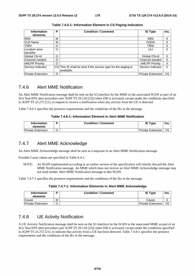
ETSI
ETSI TS 129 274 V12.6.0 (2014-10)1793GPP TS 29.274 version 12.6.0 Release 12
Table 7.4.5-1: Information Element in CS Paging Indication
Information elements
P Condition / Comment IE Type Ins.
IMSI M IMSI 0 VLR Name M FQDN 0 TMSI O TMSI 0 Location area identifier
O ULI 0
Global CN-Id O Global CN-Id 0 Channel needed O Channel needed 0 eMLPP Priority O eMLPP Priority 0 Service Indicator CO This IE shall be sent if the service type for the paging is
available. Service Indicator 0
Private Extension O Private Extension VS
7.4.6 Alert MME Notification
An Alert MME Notification message shall be sent on the S3 interface by the MME to the associated SGSN as part of an SGs Non-EPS alert procedure (see 3GPP TS 29.118 [22]) when ISR is activated, except under the conditions specified in 3GPP TS 23.272 [21], to request to receive a notification when any activity from the UE is detected.
Table 7.4.6-1 specifies the presence requirements and the conditions of the IEs in the message.
Table 7.4.6-1: Information Element in Alert MME Notification
Information elements
P Condition / Comment IE Type Ins.
Private Extension O Private Extension VS
7.4.7 Alert MME Acknowledge
An Alert MME Acknowledge message shall be sent as a response to an Alert MME Notification message.
Possible Cause values are specified in Table 8.4-1.
NOTE: An SGSN implemented according to an earlier version of the specification will silently discard the Alert MME Notification message. An MME which does not receive an Alert MME Acknowledge message may not send further Alert MME Notification message to this SGSN.
Table 7.4.7-1 specifies the presence requirements and the conditions of the IEs in the message.
Table 7.4.7-1: Information Elements in Alert MME Acknowledge
Information elements
P Condition / Comment IE Type Ins.
Cause M Cause 0 Private Extension O Private Extension VS
7.4.8 UE Activity Notification
A UE Activity Notification message shall be sent on the S3 interface by the SGSN to the associated MME as part of an SGs Non-EPS alert procedure (see 3GPP TS 29.118 [22]) when ISR is activated, except under the conditions specified in 3GPP TS 23.272 [21], to indicate that activity from a UE has been detected. Table 7.4.8-1 specifies the presence requirements and the conditions of the IEs in the message.
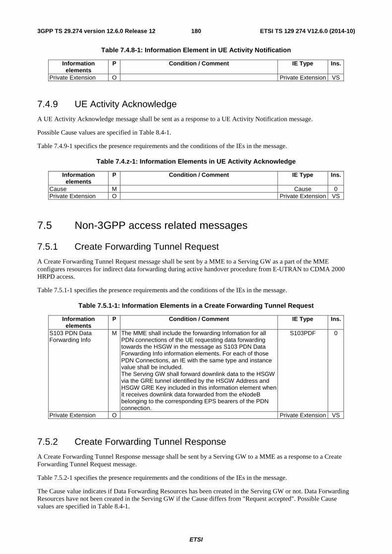
ETSI
ETSI TS 129 274 V12.6.0 (2014-10)1803GPP TS 29.274 version 12.6.0 Release 12
Table 7.4.8-1: Information Element in UE Activity Notification
Information elements
P Condition / Comment IE Type Ins.
Private Extension O Private Extension VS
7.4.9 UE Activity Acknowledge
A UE Activity Acknowledge message shall be sent as a response to a UE Activity Notification message.
Possible Cause values are specified in Table 8.4-1.
Table 7.4.9-1 specifics the presence requirements and the conditions of the IEs in the message.
Table 7.4.z-1: Information Elements in UE Activity Acknowledge
Information elements
P Condition / Comment IE Type Ins.
Cause M Cause 0 Private Extension O Private Extension VS
7.5 Non-3GPP access related messages
7.5.1 Create Forwarding Tunnel Request
A Create Forwarding Tunnel Request message shall be sent by a MME to a Serving GW as a part of the MME configures resources for indirect data forwarding during active handover procedure from E-UTRAN to CDMA 2000 HRPD access.
Table 7.5.1-1 specifies the presence requirements and the conditions of the IEs in the message.
Table 7.5.1-1: Information Elements in a Create Forwarding Tunnel Request
Information elements
P Condition / Comment IE Type Ins.
S103 PDN Data Forwarding Info
M The MME shall include the forwarding Infomation for all PDN connections of the UE requesting data forwarding towards the HSGW in the message as S103 PDN Data Forwarding Info information elements. For each of those PDN Connections, an IE with the same type and instance value shall be included. The Serving GW shall forward downlink data to the HSGW via the GRE tunnel identified by the HSGW Address and HSGW GRE Key included in this information element when it receives downlink data forwarded from the eNodeB belonging to the corresponding EPS bearers of the PDN connection.
S103PDF 0
Private Extension O Private Extension VS
7.5.2 Create Forwarding Tunnel Response
A Create Forwarding Tunnel Response message shall be sent by a Serving GW to a MME as a response to a Create Forwarding Tunnel Request message.
Table 7.5.2-1 specifies the presence requirements and the conditions of the IEs in the message.
The Cause value indicates if Data Forwarding Resources has been created in the Serving GW or not. Data Forwarding Resources have not been created in the Serving GW if the Cause differs from "Request accepted". Possible Cause values are specified in Table 8.4-1.
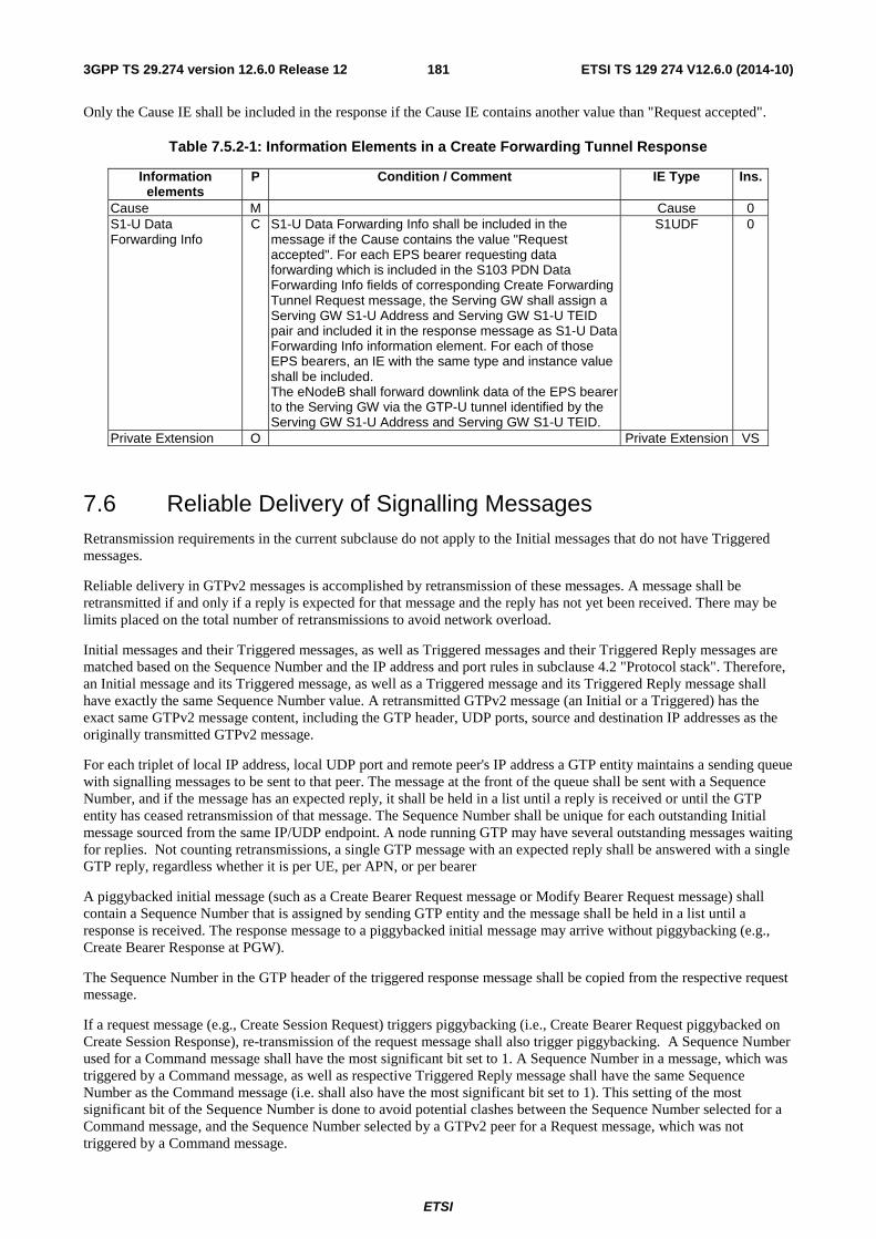
ETSI
ETSI TS 129 274 V12.6.0 (2014-10)1813GPP TS 29.274 version 12.6.0 Release 12
Only the Cause IE shall be included in the response if the Cause IE contains another value than "Request accepted".
Table 7.5.2-1: Information Elements in a Create Forwarding Tunnel Response
Information elements
P Condition / Comment IE Type Ins.
Cause M Cause 0 S1-U Data Forwarding Info
C S1-U Data Forwarding Info shall be included in the message if the Cause contains the value "Request accepted". For each EPS bearer requesting data forwarding which is included in the S103 PDN Data Forwarding Info fields of corresponding Create Forwarding Tunnel Request message, the Serving GW shall assign a Serving GW S1-U Address and Serving GW S1-U TEID pair and included it in the response message as S1-U Data Forwarding Info information element. For each of those EPS bearers, an IE with the same type and instance value shall be included. The eNodeB shall forward downlink data of the EPS bearer to the Serving GW via the GTP-U tunnel identified by the Serving GW S1-U Address and Serving GW S1-U TEID.
S1UDF 0
Private Extension O Private Extension VS
7.6 Reliable Delivery of Signalling Messages Retransmission requirements in the current subclause do not apply to the Initial messages that do not have Triggered messages.
Reliable delivery in GTPv2 messages is accomplished by retransmission of these messages. A message shall be retransmitted if and only if a reply is expected for that message and the reply has not yet been received. There may be limits placed on the total number of retransmissions to avoid network overload.
Initial messages and their Triggered messages, as well as Triggered messages and their Triggered Reply messages are matched based on the Sequence Number and the IP address and port rules in subclause 4.2 "Protocol stack". Therefore, an Initial message and its Triggered message, as well as a Triggered message and its Triggered Reply message shall have exactly the same Sequence Number value. A retransmitted GTPv2 message (an Initial or a Triggered) has the exact same GTPv2 message content, including the GTP header, UDP ports, source and destination IP addresses as the originally transmitted GTPv2 message.
For each triplet of local IP address, local UDP port and remote peer's IP address a GTP entity maintains a sending queue with signalling messages to be sent to that peer. The message at the front of the queue shall be sent with a Sequence Number, and if the message has an expected reply, it shall be held in a list until a reply is received or until the GTP entity has ceased retransmission of that message. The Sequence Number shall be unique for each outstanding Initial message sourced from the same IP/UDP endpoint. A node running GTP may have several outstanding messages waiting for replies. Not counting retransmissions, a single GTP message with an expected reply shall be answered with a single GTP reply, regardless whether it is per UE, per APN, or per bearer
A piggybacked initial message (such as a Create Bearer Request message or Modify Bearer Request message) shall contain a Sequence Number that is assigned by sending GTP entity and the message shall be held in a list until a response is received. The response message to a piggybacked initial message may arrive without piggybacking (e.g., Create Bearer Response at PGW).
The Sequence Number in the GTP header of the triggered response message shall be copied from the respective request message.
If a request message (e.g., Create Session Request) triggers piggybacking (i.e., Create Bearer Request piggybacked on Create Session Response), re-transmission of the request message shall also trigger piggybacking. A Sequence Number used for a Command message shall have the most significant bit set to 1. A Sequence Number in a message, which was triggered by a Command message, as well as respective Triggered Reply message shall have the same Sequence Number as the Command message (i.e. shall also have the most significant bit set to 1). This setting of the most significant bit of the Sequence Number is done to avoid potential clashes between the Sequence Number selected for a Command message, and the Sequence Number selected by a GTPv2 peer for a Request message, which was not triggered by a Command message.
ETSI
ETSI TS 129 274 V12.6.0 (2014-10)1823GPP TS 29.274 version 12.6.0 Release 12
A Sequence Number used for a Request message, which was not triggered by a Command message shall have the most significant bit set to 0.
A timer, denoted T3-RESPONSE, shall be started when a signalling message (for which a reply is expected) is sent. A signalling message or the triggered message has probably been lost if a reply has not been received before the T3-RESPONSE timer expires.
Once the T3-RESPONSE timer expires, the message corresponding to the T3-RESPONSE timer is then retransmitted if the total number of retry attempts is less than N3-REQUESTS times. The expiry of the timer for piggybacked request messages shall result in re-transmission of the original IP/UDP packet containing both the triggered response message and the piggybacked initial message. T3-RESPONSE timer and N3-REQUESTS counter setting is implementation dependent. That is, the timers and counters may be configurable per procedure. Multileg communications (e.g. Create Session Requests and Responses) however require longer timer values and possibly a higher number of retransmission attempts compared to single leg communication.
All received GTPv2 messages with an expected reply shall be replied to and all reply messages associated with a certain message shall always include the same information. Duplicated reply messages shall be discarded by the receiver unless the reply needs a reply. A received reply message without a matching outstanding message that is waiting for a reply should be discarded.
If a GTPv2 node is not successful with the transfer of a non-Echo signalling message, e.g. a Create Bearer Request message, it shall inform the upper layer of the unsuccessful transfer so that the controlling upper entity may take the necessary measures.
7.7 Error Handling
7.7.0 Handling Piggybacked Messages
For piggybacked initial messages, the following general rule shall apply: the triggered response message carrying the piggybacked message shall be processed first, according to the following sections. Subsequently, the piggybacked initial message shall be processed independently. If the processing of dedicated bearer activation message results in an error, this shall not affect the default bearer establishment. If the default bearer establishment fails, the dedicated bearer activation related message shall be discarded.
7.7.1 Protocol Errors
A protocol error is defined as a message or an Information Element received from a peer entity with unknown type, or if it is unexpected, or if it has an erroneous content.
The term silently discarded is used in the following subclauses to mean that the receiving GTP entity's implementation shall discard such a message without further processing, or that the receiving GTP entity discards such an IE and continues processing the message. The conditions for the receiving GTP entity to silently discard an IE are specified in the subsequent subclauses.
The handling of unknown, unexpected or erroneous GTP messages and IEs shall provide for the forward compatibility of GTP. Therefore, the sending GTP entity shall be able to safely include in a message a new conditional-optional or an optional IE. Such an IE may also have a new type value. Any legacy receiving GTP entity shall, however, silently discard such an IE and continue processing the message.
If a protocol error is detected by the receiving GTP entity, it should log the event including the erroneous message and may include the error in a statistical counter.
For Request messages and Response messages without a rejection Cause value, the following applies:
- An information element with "Mandatory" in the "Presence requirement" column of a message definition shall always be present in that message.
- An information element with "Conditional" in the "Presence requirement" column of a message definition shall be sent when the conditions detailed in the "Condition / Comment" column are met.
For Response messages containing a rejection Cause value, see subclause 6.1.1.
ETSI
ETSI TS 129 274 V12.6.0 (2014-10)1833GPP TS 29.274 version 12.6.0 Release 12
The Version Not Supported Indication message shall be considered as a Triggered message as specified in subclause 4.2.5 "Messages with GTPv2 defined replies: Classification of Initial and Triggered Messages".
The receiving GTP entity shall apply the error handling specified in the subsequent subclauses in decreasing priority.
If the received erroneous message is a reply to an outstanding GTP message, the GTP transaction layer shall stop retransmissions and notify the GTP application layer of the error even if the reply is silently discarded.
7.7.2 Different GTP Versions
If a GTPv2 entity receives a message of an unsupported GTP version, higher than GTPv2, it shall return a Version Not Supported Indication message and silently discard the received message.
If a GTPv2 entity listens to the GTPv0 port, the entity shall silently discard any received GTPv0 message.
If a GTPv2 entity does not support GTPv1 and receives a GTPv1 message, it shall silently discard the received message.
7.7.3 GTP Message of Invalid Length
If a GTP entity receives a message, which is too short to contain the respective GTPv2 header, the GTP-PDU shall be silently discarded.
Apart from a piggybacked GTP message or an Echo Request message, if a GTP entity receives a Request message within an IP/UDP packet of a length that is inconsistent with the value specified in the Length field of the GTP header, then the receiving GTP entity should log the error and shall send the Response message with Cause IE value set to "Invalid Length".
Apart from a piggybacked GTP message, if a GTP entity receives a Response message within an IP/UDP packet of a length that is inconsistent with the value specified in the Length field of the GTP header, then the receiving GTP entity should log the error and shall silently discard the message.
If a GTP entity receives two GTP messages (triggered response message and a piggybacked initial message) within an IP/UDP packet of a length that is inconsistent with the total length of the two concatenated messages as indicated by Length fields of the GTP headers, then the receiving GTP entity should log the error and return an appropriate Response message with Cause IE value set to "Invalid overall length of the triggered response message and a piggybacked initial message". That is:
- for a Create Session Response message together with a piggybacked Create Bearer Request message, a Create Bearer Response message should be returned with the above Cause value.
- for a Create Bearer Response message together with a piggybacked Modify Bearer Request message, a Modify Bearer Response message should be returned with the above Cause value.
7.7.4 Unknown GTP Message
If a GTP entity receives a message with an unknown Message Type value, it shall silently discard the message.
7.7.5 Unexpected GTP Message
If a GTP entity receives an unexpected initial message (see subclause 4.2 "Protocol stack"), it shall be silently discard the message and shall log an error.
If a GTP entity receives an unexpected triggered message (see subclause 4.2 "Protocol stack"), it shall discard the message and may log an error.
7.7.6 Missing Information Elements
A GTP entity shall check if all mandatory IEs are present in the received Request message. Apart from Echo Request message, if one or more mandatory information elements are missing in the received Request message, the GTP entity
ETSI
ETSI TS 129 274 V12.6.0 (2014-10)1843GPP TS 29.274 version 12.6.0 Release 12
should log the error and shall send a Response message with Cause IE value set to "Mandatory IE missing" together with the type and instance of the missing mandatory IE.
If a GTP entity receives a Response message with Cause IE value set to "Mandatory IE missing", it shall notify its upper layer.
A GTP entity shall check if all mandatory IEs are present in the received Response message without a rejection Cause value. If one or more mandatory information elements are missing, the GTP entity shall notify the upper layer and should log the error.
A GTP entity shall check if conditional information elements are present in the received Request message, if possible (i.e. if the receiving entity has sufficient information available to check if the respective conditions were met). If one or more conditional information elements are missing, a GTP entity should log the error and shall send a Response message with Cause IE value set to "Conditional IE missing" together with the type and instance of the missing conditional IE.
A GTP entity shall check if conditional information elements are present in the received Response message without a rejection Cause value, if possible (i.e. if the receiving entity has sufficient information available to check if the respective conditions were met). If one or more conditional information elements are missing, a GTP entity shall notify the upper layer and should log the error.
For Response messages containing a rejection Cause value, see subclause 6.1.1.
If the Indication IE is applicable for the message as a conditional IE and if it is not present, the GTP entity shall not reject the message unless there are other reasons to reject the message.
If the Indication IE is applicable for the message as conditional IE and if it is present with the value of all the applicable flags set to "0", the GTP entity shall not reject the message unless there are other reasons to reject the message.
Absence of an optional information element shall not trigger any of the error handling processes.
7.7.7 Invalid Length Information Element
An information element has invalid length when the actual length of the IE is different from the value of the Length field in the IE header. Here, the actual length of the IE means the length of the content field of the received IE.
If a GTP message contains more than one information elements and one or more of them have invalid length, the receiving GTP entity can detect which of the IEs have invalid length only in the following cases:
- If the Length value in the IE header is greater than the overall length of the message;
- If the invalid length IE is the last one in the message.
Apart from Echo Request message, if a receiving GTP entity detects information element with invalid length in a Request message, it shall send an appropriate error response with Cause IE value set to "Invalid length" together with the type and instance of the offending IE.
Other Length field handling cases are specified below:
- If the received value of the Length field and the actual length of the fixed length IE are consistent, but the length is greater than that expected by the fixed number of octets, then the extra octets shall be discarded.
- If the received value of the Length field and the actual length of the fixed length IE are consistent, but the length is less than that expected by the fixed number of octets, this shall be considered an error, IE shall be discarded and if the IE was received as a Mandatory IE or a verifiable Conditional IE in a Request message, an appropriate error response with Cause IE value set to "Invalid length" together with the type and instance of the offending IE shall be returned to the sender.
- If the received value of the Length field and the actual length of the extendable length IE are consistent, but the length is greater than that expected by the fixed number of octets preceding the extended field(s), then the extra unknown octets shall be discarded.
- If the received value of the Length field and the actual length of the extendable length IE are consistent, but the length is less than the number of fixed octets defined for that IE, preceding the extended field(s), this shall be considered an error, IE shall be discarded and if the IE was received as a Mandatory IE or a verifiable
ETSI
ETSI TS 129 274 V12.6.0 (2014-10)1853GPP TS 29.274 version 12.6.0 Release 12
Conditional IE in a Request message, an appropriate error response with Cause IE value set to "Invalid length" together with the type and instance of the offending IE shall be returned to the sender. Please refer to Table 8.1-1 for determining the number of fixed octets of an IE.
7.7.8 Semantically incorrect Information Element
Apart from Echo Request message, the receiver of a GTP signalling message Request including a mandatory or a verifiable conditional information element with a semantically invalid Value shall discard the request, should log the error, and shall send a response with Cause set to "Mandatory IE incorrect" together with a type and instance of the offending IE.
The receiver of a GTP signalling message Response including a mandatory or a verifiable conditional information element with a semantically invalid Value shall notify the upper layer that a message with this sequence number has been received and should log the error.
If a GTP entity receives an information element with a value which is shown as reserved, it shall treat that information element as invalid and should log the error. If the invalid IE is received in a Request, and it is a mandatory IE or a verifiable conditional IE, the GTP entity shall send a response with Cause set to "Mandatory IE incorrect " together with a type and instance of the offending IE.
The principle is: the use of reserved values invokes error handling; the use of spare values can be silently discarded and so in the case of IEs with spare values used, processing shall be continued ignoring the spare values.
The receiver of a GTP signalling message including an optional information element with a Value that is not in the range defined for this information element value shall discard this IE, but shall treat the rest of the message as if this IE was absent and continue processing. The receiver shall not check the content of an information element field that is defined as 'spare".
All semantically incorrect optional information elements in a GTP signalling message shall be treated as not present in the message.
7.7.9 Unknown or unexpected Information Element
The receiver of a GTP message including an unexpected information element with known Type value, but with the instance value that is not defined for this message shall discard the IE and log an error. The receiver shall process the message.
An information element with a Type value which is defined in section 8.1 of the present specification but whose Instance Value is not expected in the received GTP signalling message according to the grammar defined in section 7 of the present specification shall be silently discarded (skipped) and the rest of the message processed as if this information element was not present.
NOTE: An Information Element in an encoded GTPv2 message or grouped IE is identified by the pair of IE Type and Instance value.
7.7.10 Repeated Information Elements
An Information Element is repeated if there is more than one IE with the same IE Type and Instance in the scope of the GTP message (scope of the grouped IE). Such an IE is a member in a list.
If an information element is repeated in a GTP signalling message in which repetition of the information element is not specified, only the contents of the information element appearing first shall be handled and all subsequent repetitions of the information element shall be ignored. When repetition of information elements is specified, only the contents of specified repeated information elements shall be handled and all subsequent repetitions of the information element shall be ignored.
7.7.11 TFT Error Handling
TFT related error handling for EUTRAN is specified in 3GPP TS 24.301 [23] and for UTRAN/GERAN in 3GPP TS 24.008 [5].
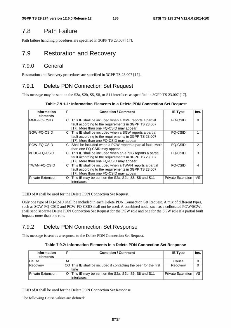
ETSI
ETSI TS 129 274 V12.6.0 (2014-10)1863GPP TS 29.274 version 12.6.0 Release 12
7.8 Path Failure Path failure handling procedures are specified in 3GPP TS 23.007 [17].
7.9 Restoration and Recovery
7.9.0 General
Restoration and Recovery procedures are specified in 3GPP TS 23.007 [17].
7.9.1 Delete PDN Connection Set Request
This message may be sent on the S2a, S2b, S5, S8, or S11 interfaces as specified in 3GPP TS 23.007 [17].
Table 7.9.1-1: Information Elements in a Delete PDN Connection Set Request
Information elements
P Condition / Comment IE Type Ins.
MME-FQ-CSID C This IE shall be included when a MME reports a partial fault according to the requirements in 3GPP TS 23.007 [17]. More than one FQ-CSID may appear.
FQ-CSID 0
SGW-FQ-CSID C This IE shall be included when a SGW reports a partial fault according to the requirements in 3GPP TS 23.007 [17]. More than one FQ-CSID may appear.
FQ-CSID 1
PGW-FQ-CSID C Shall be included when a PGW reports a partial fault. More than one FQ-CSID may appear
FQ-CSID 2
ePDG-FQ-CSID C This IE shall be included when an ePDG reports a partial fault according to the requirements in 3GPP TS 23.007 [17]. More than one FQ-CSID may appear.
FQ-CSID 3
TWAN-FQ-CSID C This IE shall be included when a TWAN reports a partial fault according to the requirements in 3GPP TS 23.007 [17]. More than one FQ-CSID may appear.
FQ-CSID 4
Private Extension O This IE may be sent on the S2a, S2b, S5, S8 and S11 interfaces.
Private Extension VS
TEID of 0 shall be used for the Delete PDN Connection Set Request.
Only one type of FQ-CSID shall be included in each Delete PDN Connection Set Request, A mix of different types, such as SGW-FQ-CSID and PGW-FQ-CSID shall not be used. A combined node, such as a collocated PGW/SGW, shall send separate Delete PDN Connection Set Request for the PGW role and one for the SGW role if a partial fault impacts more than one role.
7.9.2 Delete PDN Connection Set Response
This message is sent as a response to the Delete PDN Connection Set Request.
Table 7.9.2: Information Elements in a Delete PDN Connection Set Response
Information elements
P Condition / Comment IE Type Ins.
Cause M Cause 0 Recovery CO This IE shall be included if contacting the peer for the first
time Recovery 0
Private Extension O This IE may be sent on the S2a, S2b, S5, S8 and S11 interfaces.
Private Extension VS
TEID of 0 shall be used for the Delete PDN Connection Set Response.
The following Cause values are defined:
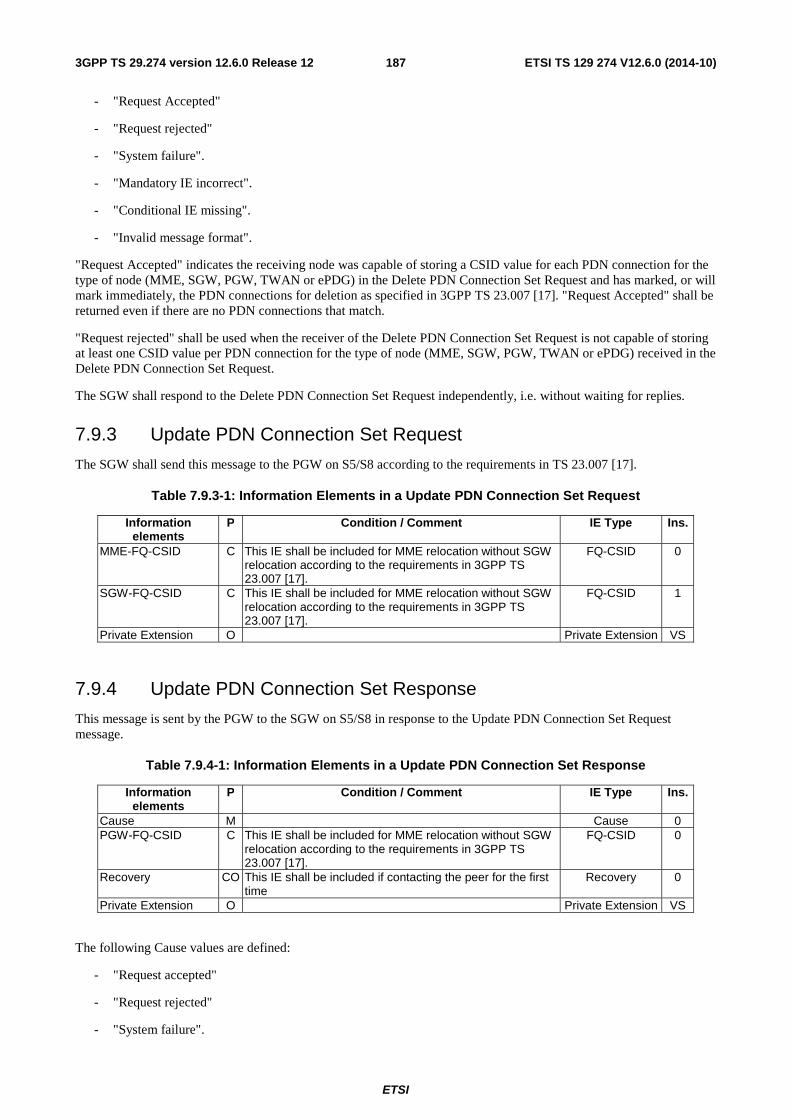
ETSI
ETSI TS 129 274 V12.6.0 (2014-10)1873GPP TS 29.274 version 12.6.0 Release 12
- "Request Accepted"
- "Request rejected"
- "System failure".
- "Mandatory IE incorrect".
- "Conditional IE missing".
- "Invalid message format".
"Request Accepted" indicates the receiving node was capable of storing a CSID value for each PDN connection for the type of node (MME, SGW, PGW, TWAN or ePDG) in the Delete PDN Connection Set Request and has marked, or will mark immediately, the PDN connections for deletion as specified in 3GPP TS 23.007 [17]. "Request Accepted" shall be returned even if there are no PDN connections that match.
"Request rejected" shall be used when the receiver of the Delete PDN Connection Set Request is not capable of storing at least one CSID value per PDN connection for the type of node (MME, SGW, PGW, TWAN or ePDG) received in the Delete PDN Connection Set Request.
The SGW shall respond to the Delete PDN Connection Set Request independently, i.e. without waiting for replies.
7.9.3 Update PDN Connection Set Request
The SGW shall send this message to the PGW on S5/S8 according to the requirements in TS 23.007 [17].
Table 7.9.3-1: Information Elements in a Update PDN Connection Set Request
Information elements
P Condition / Comment IE Type Ins.
MME-FQ-CSID C This IE shall be included for MME relocation without SGW relocation according to the requirements in 3GPP TS 23.007 [17].
FQ-CSID 0
SGW-FQ-CSID C This IE shall be included for MME relocation without SGW relocation according to the requirements in 3GPP TS 23.007 [17].
FQ-CSID 1
Private Extension O Private Extension VS
7.9.4 Update PDN Connection Set Response
This message is sent by the PGW to the SGW on S5/S8 in response to the Update PDN Connection Set Request message.
Table 7.9.4-1: Information Elements in a Update PDN Connection Set Response
Information elements
P Condition / Comment IE Type Ins.
Cause M Cause 0 PGW-FQ-CSID C This IE shall be included for MME relocation without SGW
relocation according to the requirements in 3GPP TS 23.007 [17].
FQ-CSID 0
Recovery CO This IE shall be included if contacting the peer for the first time
Recovery 0
Private Extension O Private Extension VS
The following Cause values are defined:
- "Request accepted"
- "Request rejected"
- "System failure".
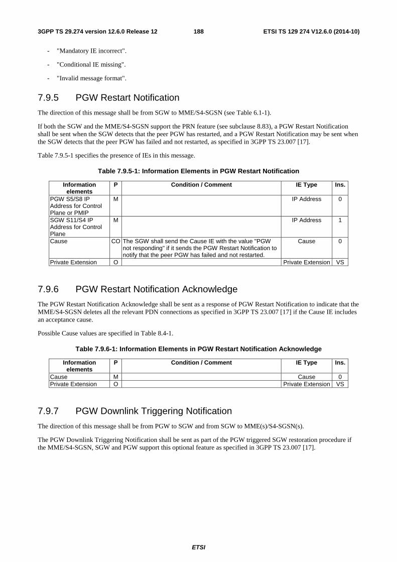
ETSI
ETSI TS 129 274 V12.6.0 (2014-10)1883GPP TS 29.274 version 12.6.0 Release 12
- "Mandatory IE incorrect".
- "Conditional IE missing".
- "Invalid message format".
7.9.5 PGW Restart Notification
The direction of this message shall be from SGW to MME/S4-SGSN (see Table 6.1-1).
If both the SGW and the MME/S4-SGSN support the PRN feature (see subclause 8.83), a PGW Restart Notification shall be sent when the SGW detects that the peer PGW has restarted, and a PGW Restart Notification may be sent when the SGW detects that the peer PGW has failed and not restarted, as specified in 3GPP TS 23.007 [17].
Table 7.9.5-1 specifies the presence of IEs in this message.
Table 7.9.5-1: Information Elements in PGW Restart Notification
Information elements
P Condition / Comment IE Type Ins.
PGW S5/S8 IP Address for Control Plane or PMIP
M IP Address 0
SGW S11/S4 IP Address for Control Plane
M
IP Address 1
Cause CO The SGW shall send the Cause IE with the value "PGW not responding" if it sends the PGW Restart Notification to notify that the peer PGW has failed and not restarted.
Cause 0
Private Extension O Private Extension VS
7.9.6 PGW Restart Notification Acknowledge
The PGW Restart Notification Acknowledge shall be sent as a response of PGW Restart Notification to indicate that the MME/S4-SGSN deletes all the relevant PDN connections as specified in 3GPP TS 23.007 [17] if the Cause IE includes an acceptance cause.
Possible Cause values are specified in Table 8.4-1.
Table 7.9.6-1: Information Elements in PGW Restart Notification Acknowledge
Information elements
P Condition / Comment IE Type Ins.
Cause M Cause 0 Private Extension O Private Extension VS
7.9.7 PGW Downlink Triggering Notification
The direction of this message shall be from PGW to SGW and from SGW to MME(s)/S4-SGSN(s).
The PGW Downlink Triggering Notification shall be sent as part of the PGW triggered SGW restoration procedure if the MME/S4-SGSN, SGW and PGW support this optional feature as specified in 3GPP TS 23.007 [17].
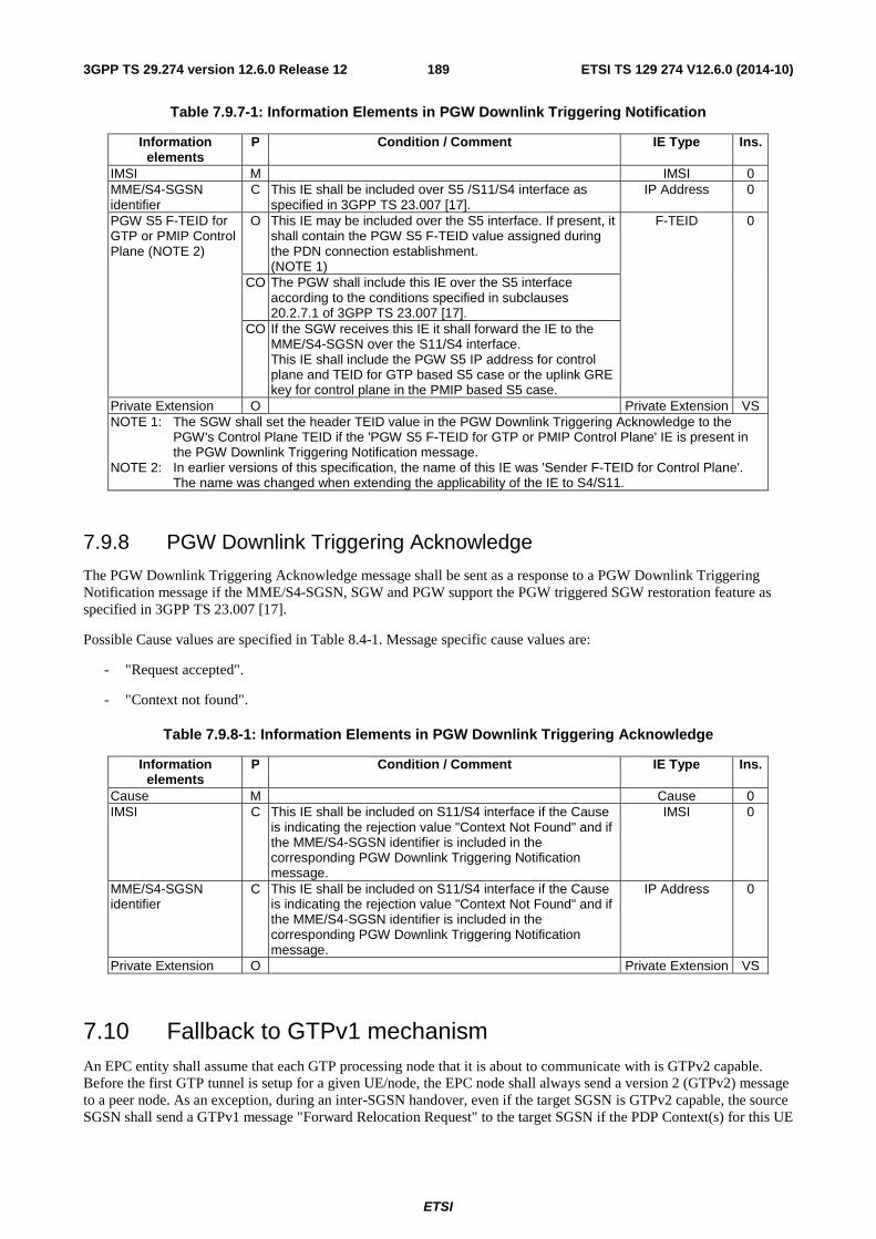
ETSI
ETSI TS 129 274 V12.6.0 (2014-10)1893GPP TS 29.274 version 12.6.0 Release 12
Table 7.9.7-1: Information Elements in PGW Downlink Triggering Notification
Information elements
P Condition / Comment IE Type Ins.
IMSI M IMSI 0 MME/S4-SGSN identifier
C This IE shall be included over S5 /S11/S4 interface as specified in 3GPP TS 23.007 [17].
IP Address 0
PGW S5 F-TEID for GTP or PMIP Control Plane (NOTE 2)
O This IE may be included over the S5 interface. If present, it shall contain the PGW S5 F-TEID value assigned during the PDN connection establishment. (NOTE 1)
F-TEID 0
CO The PGW shall include this IE over the S5 interface according to the conditions specified in subclauses 20.2.7.1 of 3GPP TS 23.007 [17].
CO If the SGW receives this IE it shall forward the IE to the MME/S4-SGSN over the S11/S4 interface. This IE shall include the PGW S5 IP address for control plane and TEID for GTP based S5 case or the uplink GRE key for control plane in the PMIP based S5 case.
Private Extension O Private Extension VS NOTE 1: The SGW shall set the header TEID value in the PGW Downlink Triggering Acknowledge to the
PGW's Control Plane TEID if the 'PGW S5 F-TEID for GTP or PMIP Control Plane' IE is present in the PGW Downlink Triggering Notification message.
NOTE 2: In earlier versions of this specification, the name of this IE was 'Sender F-TEID for Control Plane'. The name was changed when extending the applicability of the IE to S4/S11.
7.9.8 PGW Downlink Triggering Acknowledge
The PGW Downlink Triggering Acknowledge message shall be sent as a response to a PGW Downlink Triggering Notification message if the MME/S4-SGSN, SGW and PGW support the PGW triggered SGW restoration feature as specified in 3GPP TS 23.007 [17].
Possible Cause values are specified in Table 8.4-1. Message specific cause values are:
- "Request accepted".
- "Context not found".
Table 7.9.8-1: Information Elements in PGW Downlink Triggering Acknowledge
Information elements
P Condition / Comment IE Type Ins.
Cause M Cause 0 IMSI C This IE shall be included on S11/S4 interface if the Cause
is indicating the rejection value "Context Not Found" and if the MME/S4-SGSN identifier is included in the corresponding PGW Downlink Triggering Notification message.
IMSI 0
MME/S4-SGSN identifier
C This IE shall be included on S11/S4 interface if the Cause is indicating the rejection value "Context Not Found" and if the MME/S4-SGSN identifier is included in the corresponding PGW Downlink Triggering Notification message.
IP Address 0
Private Extension O Private Extension VS
7.10 Fallback to GTPv1 mechanism An EPC entity shall assume that each GTP processing node that it is about to communicate with is GTPv2 capable. Before the first GTP tunnel is setup for a given UE/node, the EPC node shall always send a version 2 (GTPv2) message to a peer node. As an exception, during an inter-SGSN handover, even if the target SGSN is GTPv2 capable, the source SGSN shall send a GTPv1 message "Forward Relocation Request" to the target SGSN if the PDP Context(s) for this UE

ETSI
ETSI TS 129 274 V12.6.0 (2014-10)1903GPP TS 29.274 version 12.6.0 Release 12
were established to GGSN(s), or if there is no active PDP context and the source or target SGSN does not support SRNS relocation w/o PDN connection over GTPv2 (see subclause 7.3.1).
A GTPv2 entity shall fallback to GTPv1 only if either a "Version Not Supported" message in GTPv1 format as specified in 3GPP TS 29.060 [4] is received from the peer node (this indicates that the peer GTP entity does not support GTPv2), or if a GTPv2 message is received with Cause value "Fallback to GTPv1".
If a GTPv1 "Version Not Supported" message in received, a GTPv2 entity may fallback to GTPv1. 3GPP TS 23.401 [3] (see annex D) and 3GPP TS 23.060 [35] specify GTP version usage during the mobility between a UTRAN/GERAN and an E-UTRAN.
A GTPv2 entity may receive a GTPv2 message with a Cause value "Fallback to GTPv1" in the following cases:
- an S4 SGSN receives the Cause code "Fallback to GTPv1" in a GTPv2 Context Response message over S16 interface. When an UE has activated a PDP context via S4 SGSN to GGSN and inter-SGSN RAU is underway, the old S4 SGSN shall include the Cause value "Fallback to GTPv1" in a GTPv2 Context Response message over S16 interface. In this case, the new S4 SGSN shall abort the ongoing GTPv2 procedure and send a GTPv1 "SGSN Context Request" message to the old S4 SGSN. The fallback to GTPv1 is performed only for this UE in the current procedure.
- an MME receives the Cause code "Fallback to GTPv1" in a GTPv2 Context Response message over the S3 interface. When an UE has active PDP context(s) via an S4 SGSN and a TAU is underway, the old S4 SGSN may include the Cause value "Fallback to GTPv1" in a GTPv2 Context Response message over the S3 interface. In this case, the MME shall abort the ongoing GTPv2 procedure and should send a GTPv1 "SGSN Context Request" message to the old S4 SGSN. The fallback to GTPv1 is performed only for this UE.
Fallback to GTPv1 shall not occur on already established GTP tunnels without change of the peer nodes of the communication bearer.
7.11 Fallback to GTPv0 Fallback from GTPv2 to GTPv0 shall not be supported. Therefore, GTPv2 entity should not listen to the well-known GTPv0 port 3386.
7.12 Trace Management Messages
7.12.1 Trace Session Activation
The Trace Session Activation message shall be sent on S11/S4 by the MME/SGSN to the SGW, on S2a/S2b by the TWAN/ePDG to the PGW, and on S5/S8 by the SGW to the PGW when session trace is activated for a particular IMSI or IMEI for a UE that is attached and active or attached and idle.
Table 7.12.1-1 specifies the presence of the IEs in the message.
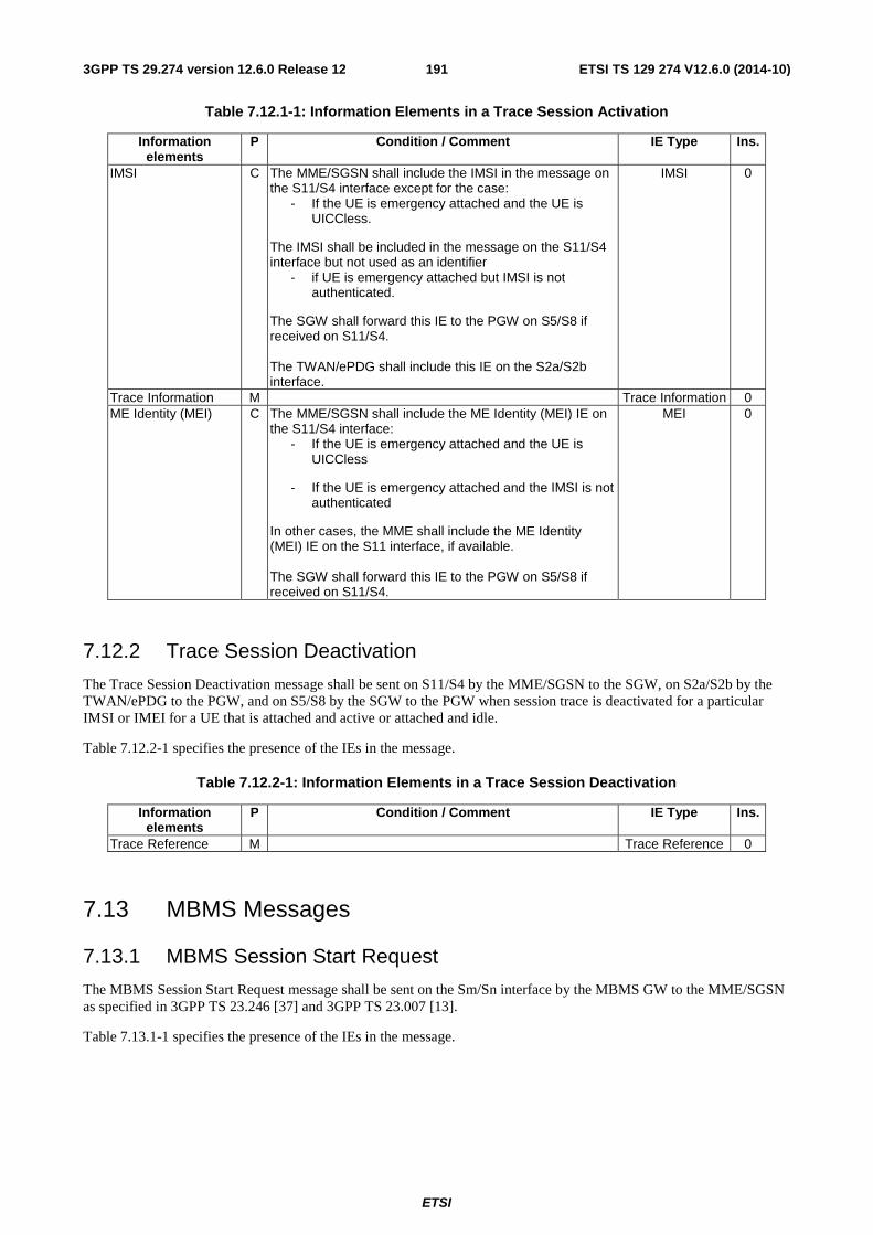
ETSI
ETSI TS 129 274 V12.6.0 (2014-10)1913GPP TS 29.274 version 12.6.0 Release 12
Table 7.12.1-1: Information Elements in a Trace Session Activation
Information elements
P Condition / Comment IE Type Ins.
IMSI C The MME/SGSN shall include the IMSI in the message on the S11/S4 interface except for the case:
- If the UE is emergency attached and the UE is UICCless.
The IMSI shall be included in the message on the S11/S4 interface but not used as an identifier
- if UE is emergency attached but IMSI is not authenticated.
The SGW shall forward this IE to the PGW on S5/S8 if received on S11/S4. The TWAN/ePDG shall include this IE on the S2a/S2b interface.
IMSI 0
Trace Information M Trace Information 0 ME Identity (MEI) C The MME/SGSN shall include the ME Identity (MEI) IE on
the S11/S4 interface: - If the UE is emergency attached and the UE is
UICCless
- If the UE is emergency attached and the IMSI is not authenticated
In other cases, the MME shall include the ME Identity (MEI) IE on the S11 interface, if available. The SGW shall forward this IE to the PGW on S5/S8 if received on S11/S4.
MEI 0
7.12.2 Trace Session Deactivation
The Trace Session Deactivation message shall be sent on S11/S4 by the MME/SGSN to the SGW, on S2a/S2b by the TWAN/ePDG to the PGW, and on S5/S8 by the SGW to the PGW when session trace is deactivated for a particular IMSI or IMEI for a UE that is attached and active or attached and idle.
Table 7.12.2-1 specifies the presence of the IEs in the message.
Table 7.12.2-1: Information Elements in a Trace Session Deactivation
Information elements
P Condition / Comment IE Type Ins.
Trace Reference M Trace Reference 0
7.13 MBMS Messages
7.13.1 MBMS Session Start Request
The MBMS Session Start Request message shall be sent on the Sm/Sn interface by the MBMS GW to the MME/SGSN as specified in 3GPP TS 23.246 [37] and 3GPP TS 23.007 [13].
Table 7.13.1-1 specifies the presence of the IEs in the message.
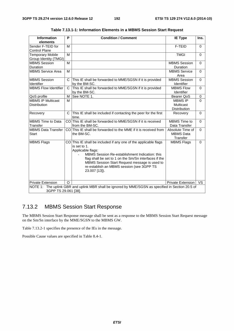
ETSI
ETSI TS 129 274 V12.6.0 (2014-10)1923GPP TS 29.274 version 12.6.0 Release 12
Table 7.13.1-1: Information Elements in a MBMS Session Start Request
Information elements
P Condition / Comment IE Type Ins.
Sender F-TEID for Control Plane
M F-TEID 0
Temporary Mobile Group Identity (TMGI)
M TMGI 0
MBMS Session Duration
M MBMS Session Duration
0
MBMS Service Area M MBMS Service Area
0
MBMS Session Identifier
C This IE shall be forwarded to MME/SGSN if it is provided by the BM-SC.
MBMS Session Identifier
0
MBMS Flow Identifier C This IE shall be forwarded to MME/SGSN if it is provided by the BM-SC.
MBMS Flow Identifier
0
QoS profile M See NOTE 1. Bearer QoS 0 MBMS IP Multicast Distribution
M MBMS IP Multicast
Distribution
0
Recovery C This IE shall be included if contacting the peer for the first time.
Recovery 0
MBMS Time to Data Transfer
CO This IE shall be forwarded to MME/SGSN if it is received from the BM-SC.
MBMS Time to Data Transfer
0
MBMS Data Transfer Start
CO This IE shall be forwarded to the MME if it is received from the BM-SC.
Absolute Time of MBMS Data
Transfer
0
MBMS Flags CO This IE shall be included if any one of the applicable flags is set to 1. Applicable flags:
- MBMS Session Re-establishment Indication: this flag shall be set to 1 on the Sm/Sn interfaces if the MBMS Session Start Request message is used to re-establish an MBMS session (see 3GPP TS 23.007 [13]).
MBMS Flags 0
Private Extension O Private Extension VS NOTE 1: The uplink GBR and uplink MBR shall be ignored by MME/SGSN as specified in Section 20.5 of
3GPP TS 29.061 [38].
7.13.2 MBMS Session Start Response
The MBMS Session Start Response message shall be sent as a response to the MBMS Session Start Request message on the Sm/Sn interface by the MME/SGSN to the MBMS GW.
Table 7.13.2-1 specifies the presence of the IEs in the message.
Possible Cause values are specified in Table 8.4-1.
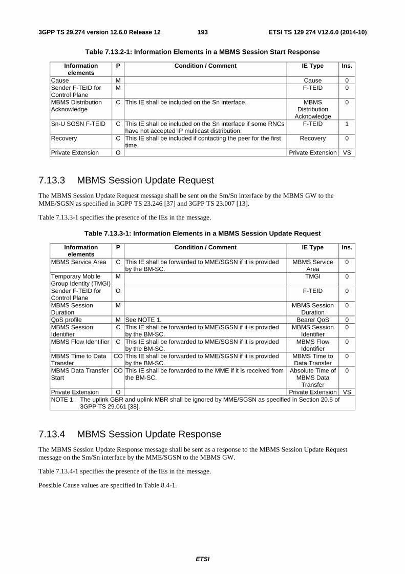
ETSI
ETSI TS 129 274 V12.6.0 (2014-10)1933GPP TS 29.274 version 12.6.0 Release 12
Table 7.13.2-1: Information Elements in a MBMS Session Start Response
Information elements
P Condition / Comment IE Type Ins.
Cause M Cause 0 Sender F-TEID for Control Plane
M F-TEID 0
MBMS Distribution Acknowledge
C This IE shall be included on the Sn interface. MBMS Distribution
Acknowledge
0
Sn-U SGSN F-TEID C This IE shall be included on the Sn interface if some RNCs have not accepted IP multicast distribution.
F-TEID 1
Recovery C This IE shall be included if contacting the peer for the first time.
Recovery 0
Private Extension O Private Extension VS
7.13.3 MBMS Session Update Request
The MBMS Session Update Request message shall be sent on the Sm/Sn interface by the MBMS GW to the MME/SGSN as specified in 3GPP TS 23.246 [37] and 3GPP TS 23.007 [13].
Table 7.13.3-1 specifies the presence of the IEs in the message.
Table 7.13.3-1: Information Elements in a MBMS Session Update Request
Information elements
P Condition / Comment IE Type Ins.
MBMS Service Area C This IE shall be forwarded to MME/SGSN if it is provided by the BM-SC.
MBMS Service Area
0
Temporary Mobile Group Identity (TMGI)
M TMGI 0
Sender F-TEID for Control Plane
O F-TEID 0
MBMS Session Duration
M MBMS Session Duration
0
QoS profile M See NOTE 1. Bearer QoS 0 MBMS Session Identifier
C This IE shall be forwarded to MME/SGSN if it is provided by the BM-SC.
MBMS Session Identifier
0
MBMS Flow Identifier C This IE shall be forwarded to MME/SGSN if it is provided by the BM-SC.
MBMS Flow Identifier
0
MBMS Time to Data Transfer
CO This IE shall be forwarded to MME/SGSN if it is provided by the BM-SC.
MBMS Time to Data Transfer
0
MBMS Data Transfer Start
CO This IE shall be forwarded to the MME if it is received from the BM-SC.
Absolute Time of MBMS Data
Transfer
0
Private Extension O Private Extension VS NOTE 1: The uplink GBR and uplink MBR shall be ignored by MME/SGSN as specified in Section 20.5 of
3GPP TS 29.061 [38].
7.13.4 MBMS Session Update Response
The MBMS Session Update Response message shall be sent as a response to the MBMS Session Update Request message on the Sm/Sn interface by the MME/SGSN to the MBMS GW.
Table 7.13.4-1 specifies the presence of the IEs in the message.
Possible Cause values are specified in Table 8.4-1.
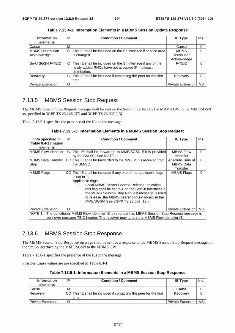
ETSI
ETSI TS 129 274 V12.6.0 (2014-10)1943GPP TS 29.274 version 12.6.0 Release 12
Table 7.13.4-1: Information Elements in a MBMS Session Update Response
Information elements
P Condition / Comment IE Type Ins.
Cause M Cause 0 MBMS Distribution Acknowledge
C This IE shall be included on the Sn interface if service area is changed.
MBMS Distribution
Acknowledge
0
Sn-U SGSN F-TEID C This IE shall be included on the Sn interface if any of the newly added RNCs have not accepted IP multicast distribution.
F-TEID 0
Recovery C This IE shall be included if contacting the peer for the first time.
Recovery 0
Private Extension O Private Extension VS
7.13.5 MBMS Session Stop Request
The MBMS Session Stop Request message shall be sent on the Sm/Sn interface by the MBMS GW to the MME/SGSN as specified in 3GPP TS 23.246 [37] and 3GPP TS 23.007 [13].
Table 7.13.5-1 specifies the presence of the IEs in the message.
Table 7.13.5-1: Information Elements in a MBMS Session Stop Request
Info specified in Table 8.4-1.rmation
elements
P Condition / Comment IE Type Ins.
MBMS Flow Identifier C This IE shall be forwarded to MME/SGSN if it is provided by the BM-SC. See NOTE 1.
MBMS Flow Identifier
0
MBMS Data Transfer Stop
CO This IE shall be forwarded to the MME if it is received from the BM-SC.
Absolute Time of MBMS Data
Transfer
0
MBMS Flags CO This IE shall be included if any one of the applicable flags is set to 1. Applicable flags:
- Local MBMS Bearer Context Release Indication: this flag shall be set to 1 on the Sm/Sn interfaces if the MBMS Session Stop Request message is used to release the MBMS bearer context locally in the MME/SGSN (see 3GPP TS 23.007 [13]).
MBMS Flags 0
Private Extension O Private Extension VS NOTE 1: The conditional MBMS Flow Identifier IE is redundant as MBMS Session Stop Request message is
sent over non-zero TEID header. The receiver may ignore the MBMS Flow Identifier IE.
7.13.6 MBMS Session Stop Response
The MBMS Session Stop Response message shall be sent as a response to the MBMS Session Stop Request message on the Sm/Sn interface by the MME/SGSN to the MBMS GW.
Table 7.13.6-1 specifies the presence of the IEs in the message.
Possible Cause values are are specified in Table 8.4-1.
Table 7.13.6-1: Information Elements in a MBMS Session Stop Response
Information elements
P Condition / Comment IE Type Ins.
Cause M Cause 0 Recovery CO This IE shall be included if contacting the peer for the first
time. Recovery 0
Private Extension O Private Extension VS
ETSI
ETSI TS 129 274 V12.6.0 (2014-10)1953GPP TS 29.274 version 12.6.0 Release 12
8 GTP-C Information Elements
8.1 Information Element Types A GTP control plane (signalling) message may contain several information elements. In order to have forward compatible type definitions for the GTPv2 information elements, all of them shall be TLIV (Type, Length, Instance, Value) coded. GTPv2 information element type values are specified in the Table 8.1-1. The last column of this table indicates whether the information element is:
- Fixed Length: the IE has a fixed set of fields, and a fixed number of octets.
- Variable Length: the IE has a fixed set of fields, and has a variable number of octets. For example, the last octets may be numbered similar to "5 to (n+4)". In this example, if the value of the length field, n, is 0, then the last field is not present.
- Extendable: the IE has a variable number of fields, and has a variable number of octets. The last fields are typically specified with the statement: "These octet(s) is/are present only if explicitly specified". The legacy receiving entity shall ignore the unknown octets.
In order to improve the efficiency of troubleshooting, it is recommended that the information elements should be arranged in the signalling messages as well as in the grouped IEs, according to the order the information elements are listed in the message definition table or grouped IE definition table in section 7. However the receiving entity shall be prepared to handle the messages with information elements in any order.
Within information elements, certain fields may be described as spare. These bits shall be transmitted with the value set to 0. To allow for future features, the receiver shall not evaluate these bits. GTPv2-C information elements that have similar semantics in GTPv1-C shall be converted into GTPv1-C format, as specified in TS 29.060 [4], before sending them to a pre-R8 GSN.
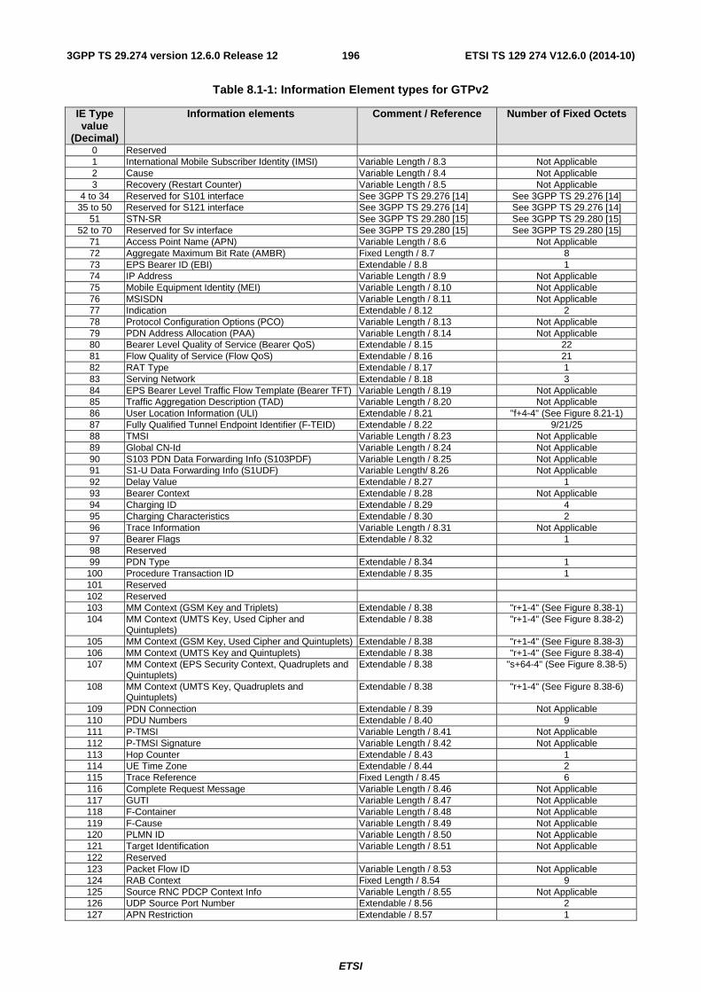
ETSI
ETSI TS 129 274 V12.6.0 (2014-10)1963GPP TS 29.274 version 12.6.0 Release 12
Table 8.1-1: Information Element types for GTPv2
IE Type value
(Decimal)
Information elements Comment / Reference Number of Fixed Octets
0 Reserved 1 International Mobile Subscriber Identity (IMSI) Variable Length / 8.3 Not Applicable 2 Cause Variable Length / 8.4 Not Applicable 3 Recovery (Restart Counter) Variable Length / 8.5 Not Applicable
4 to 34 Reserved for S101 interface See 3GPP TS 29.276 [14] See 3GPP TS 29.276 [14] 35 to 50 Reserved for S121 interface See 3GPP TS 29.276 [14] See 3GPP TS 29.276 [14]
51 STN-SR See 3GPP TS 29.280 [15] See 3GPP TS 29.280 [15] 52 to 70 Reserved for Sv interface See 3GPP TS 29.280 [15] See 3GPP TS 29.280 [15]
71 Access Point Name (APN) Variable Length / 8.6 Not Applicable 72 Aggregate Maximum Bit Rate (AMBR) Fixed Length / 8.7 8 73 EPS Bearer ID (EBI) Extendable / 8.8 1 74 IP Address Variable Length / 8.9 Not Applicable 75 Mobile Equipment Identity (MEI) Variable Length / 8.10 Not Applicable 76 MSISDN Variable Length / 8.11 Not Applicable 77 Indication Extendable / 8.12 2 78 Protocol Configuration Options (PCO) Variable Length / 8.13 Not Applicable 79 PDN Address Allocation (PAA) Variable Length / 8.14 Not Applicable 80 Bearer Level Quality of Service (Bearer QoS) Extendable / 8.15 22 81 Flow Quality of Service (Flow QoS) Extendable / 8.16 21 82 RAT Type Extendable / 8.17 1 83 Serving Network Extendable / 8.18 3 84 EPS Bearer Level Traffic Flow Template (Bearer TFT) Variable Length / 8.19 Not Applicable 85 Traffic Aggregation Description (TAD) Variable Length / 8.20 Not Applicable 86 User Location Information (ULI) Extendable / 8.21 "f+4-4" (See Figure 8.21-1) 87 Fully Qualified Tunnel Endpoint Identifier (F-TEID) Extendable / 8.22 9/21/25 88 TMSI Variable Length / 8.23 Not Applicable 89 Global CN-Id Variable Length / 8.24 Not Applicable 90 S103 PDN Data Forwarding Info (S103PDF) Variable Length / 8.25 Not Applicable 91 S1-U Data Forwarding Info (S1UDF) Variable Length/ 8.26 Not Applicable 92 Delay Value Extendable / 8.27 1 93 Bearer Context Extendable / 8.28 Not Applicable 94 Charging ID Extendable / 8.29 4 95 Charging Characteristics Extendable / 8.30 2 96 Trace Information Variable Length / 8.31 Not Applicable 97 Bearer Flags Extendable / 8.32 1 98 Reserved 99 PDN Type Extendable / 8.34 1
100 Procedure Transaction ID Extendable / 8.35 1 101 Reserved 102 Reserved 103 MM Context (GSM Key and Triplets) Extendable / 8.38 "r+1-4" (See Figure 8.38-1) 104 MM Context (UMTS Key, Used Cipher and
Quintuplets) Extendable / 8.38 "r+1-4" (See Figure 8.38-2)
105 MM Context (GSM Key, Used Cipher and Quintuplets) Extendable / 8.38 "r+1-4" (See Figure 8.38-3) 106 MM Context (UMTS Key and Quintuplets) Extendable / 8.38 "r+1-4" (See Figure 8.38-4) 107 MM Context (EPS Security Context, Quadruplets and
Quintuplets) Extendable / 8.38 "s+64-4" (See Figure 8.38-5)
108 MM Context (UMTS Key, Quadruplets and Quintuplets)
Extendable / 8.38 "r+1-4" (See Figure 8.38-6)
109 PDN Connection Extendable / 8.39 Not Applicable 110 PDU Numbers Extendable / 8.40 9 111 P-TMSI Variable Length / 8.41 Not Applicable 112 P-TMSI Signature Variable Length / 8.42 Not Applicable 113 Hop Counter Extendable / 8.43 1 114 UE Time Zone Extendable / 8.44 2 115 Trace Reference Fixed Length / 8.45 6 116 Complete Request Message Variable Length / 8.46 Not Applicable 117 GUTI Variable Length / 8.47 Not Applicable 118 F-Container Variable Length / 8.48 Not Applicable 119 F-Cause Variable Length / 8.49 Not Applicable 120 PLMN ID Variable Length / 8.50 Not Applicable 121 Target Identification Variable Length / 8.51 Not Applicable 122 Reserved 123 Packet Flow ID Variable Length / 8.53 Not Applicable 124 RAB Context Fixed Length / 8.54 9 125 Source RNC PDCP Context Info Variable Length / 8.55 Not Applicable 126 UDP Source Port Number Extendable / 8.56 2 127 APN Restriction Extendable / 8.57 1
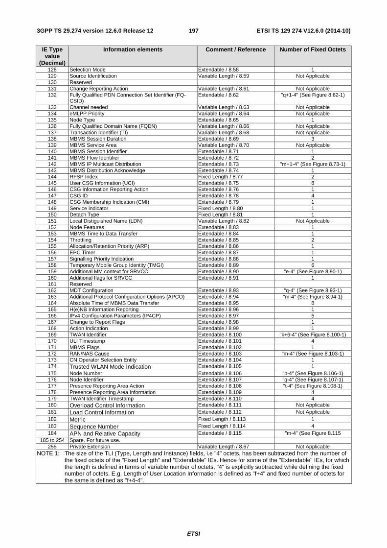
ETSI
ETSI TS 129 274 V12.6.0 (2014-10)1973GPP TS 29.274 version 12.6.0 Release 12
IE Type value
(Decimal)
Information elements Comment / Reference Number of Fixed Octets
128 Selection Mode Extendable / 8.58 1 129 Source Identification Variable Length / 8.59 Not Applicable 130 Reserved 131 Change Reporting Action Variable Length / 8.61 Not Applicable 132 Fully Qualified PDN Connection Set Identifier (FQ-
CSID) Extendable / 8.62 "q+1-4" (See Figure 8.62-1)
133 Channel needed Variable Length / 8.63 Not Applicable 134 eMLPP Priority Variable Length / 8.64 Not Applicable 135 Node Type Extendable / 8.65 1 136 Fully Qualified Domain Name (FQDN) Variable Length / 8.66 Not Applicable 137 Transaction Identifier (TI) Variable Length / 8.68 Not Applicable 138 MBMS Session Duration Extendable / 8.69 3 139 MBMS Service Area Variable Length / 8.70 Not Applicable 140 MBMS Session Identifier Extendable / 8.71 1 141 MBMS Flow Identifier Extendable / 8.72 2 142 MBMS IP Multicast Distribution Extendable / 8.73 "m+1-4" (See Figure 8.73-1) 143 MBMS Distribution Acknowledge Extendable / 8.74 1 144 RFSP Index Fixed Length / 8.77 2 145 User CSG Information (UCI) Extendable / 8.75 8 146 CSG Information Reporting Action Extendable / 8.76 1 147 CSG ID Extendable / 8.78 4 148 CSG Membership Indication (CMI) Extendable / 8.79 1 149 Service indicator Fixed Length / 8.80 1 150 Detach Type Fixed Length / 8.81 1 151 Local Distiguished Name (LDN) Variable Length / 8.82 Not Applicable 152 Node Features Extendable / 8.83 1 153 MBMS Time to Data Transfer Extendable / 8.84 1 154 Throttling Extendable / 8.85 2 155 Allocation/Retention Priority (ARP) Extendable / 8.86 1 156 EPC Timer Extendable / 8.87 1 157 Signalling Priority Indication Extendable / 8.88 1 158 Temporary Mobile Group Identity (TMGI) Extendable / 8.89 6 159 Additional MM context for SRVCC Extendable / 8.90 "e-4" (See Figure 8.90-1) 160 Additional flags for SRVCC Extendable / 8.91 1 161 Reserved 162 MDT Configuration Extendable / 8.93 "q-4" (See Figure 8.93-1) 163 Additional Protocol Configuration Options (APCO) Extendable / 8.94 "m-4" (See Figure 8.94-1) 164 Absolute Time of MBMS Data Transfer Extendable / 8.95 8 165 H(e)NB Information Reporting Extendable / 8.96 1 166 IPv4 Configuration Parameters (IP4CP) Extendable / 8.97 5 167 Change to Report Flags Extendable / 8.98 1 168 Action Indication Extendable / 8.99 1 169 TWAN Identifier Extendable / 8.100 "k+6-4" (See Figure 8.100-1) 170 ULI Timestamp Extendable / 8.101 4 171 MBMS Flags Extendable / 8.102 1 172 RAN/NAS Cause Extendable / 8.103 "m-4" (See Figure 8.103-1) 173 CN Operator Selection Entity Extendable / 8.104 1 174 Trusted WLAN Mode Indication Extendable / 8.105 1 175 Node Number Extendable / 8.106 "p-4" (See Figure 8.106-1) 176 Node Identifier Extendable / 8.107 "q-4" (See Figure 8.107-1) 177 Presence Reporting Area Action Extendable / 8.108 "t-4" (See Figure 8.108-1) 178 Presence Reporting Area Information Extendable / 8.109 4 179 TWAN Identifier Timestamp Extendable / 8.110 4 180 Overload Control Information Extendable / 8.111 Not Applicable 181 Load Control Information Extendable / 8.112 Not Applicable 182 Metric Fixed Length / 8.113 1 183 Sequence Number Fixed Length / 8.114 4 184 APN and Relative Capacity Extendable / 8.115 "m-4" (See Figure 8.115
185 to 254 Spare. For future use. 255 Private Extension Variable Length / 8.67 Not Applicable
NOTE 1: The size of the TLI (Type, Length and Instance) fields, i.e "4" octets, has been subtracted from the number of the fixed octets of the "Fixed Length" and "Extendable" IEs. Hence for some of the "Extendable" IEs, for which the length is defined in terms of variable number of octets, "4" is explicitly subtracted while defining the fixed number of octets. E.g. Length of User Location Information is defined as "f+4" and fixed number of octets for the same is defined as "f+4-4".
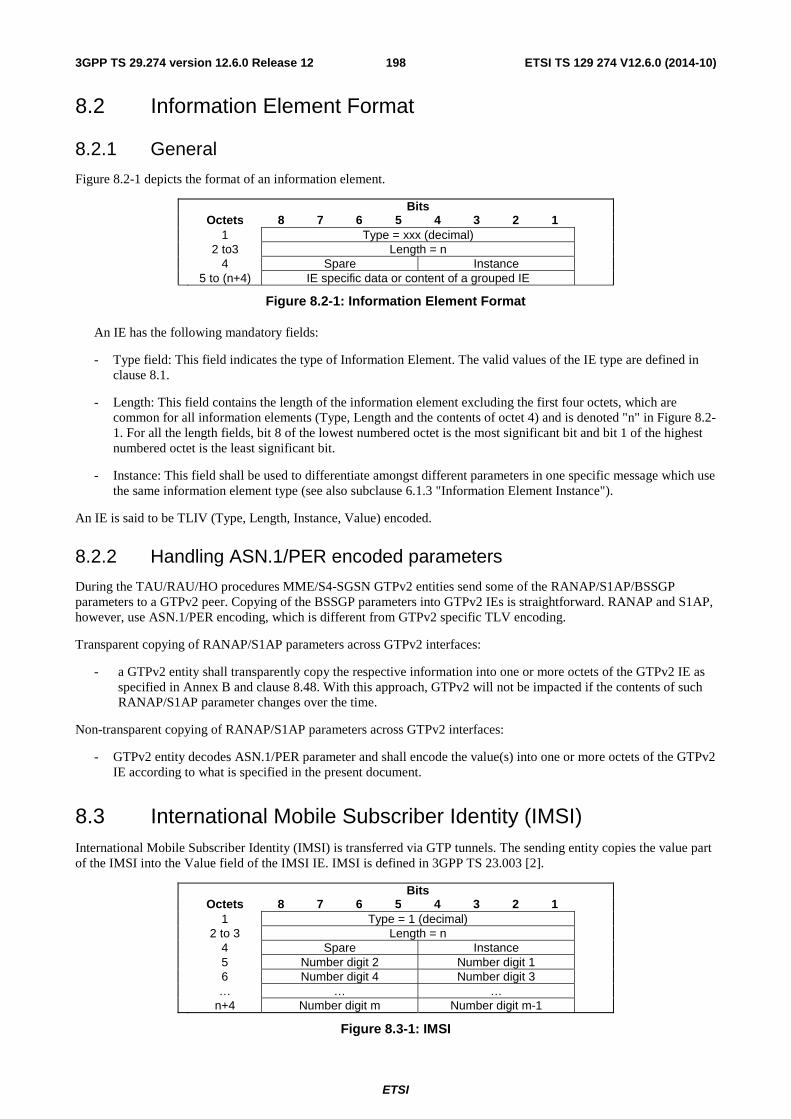
ETSI
ETSI TS 129 274 V12.6.0 (2014-10)1983GPP TS 29.274 version 12.6.0 Release 12
8.2 Information Element Format
8.2.1 General
Figure 8.2-1 depicts the format of an information element.
Bits Octets 8 7 6 5 4 3 2 1 1 Type = xxx (decimal) 2 to3 Length = n 4 Spare Instance 5 to (n+4) IE specific data or content of a grouped IE
Figure 8.2-1: Information Element Format
An IE has the following mandatory fields:
- Type field: This field indicates the type of Information Element. The valid values of the IE type are defined in clause 8.1.
- Length: This field contains the length of the information element excluding the first four octets, which are common for all information elements (Type, Length and the contents of octet 4) and is denoted "n" in Figure 8.2-1. For all the length fields, bit 8 of the lowest numbered octet is the most significant bit and bit 1 of the highest numbered octet is the least significant bit.
- Instance: This field shall be used to differentiate amongst different parameters in one specific message which use the same information element type (see also subclause 6.1.3 "Information Element Instance").
An IE is said to be TLIV (Type, Length, Instance, Value) encoded.
8.2.2 Handling ASN.1/PER encoded parameters
During the TAU/RAU/HO procedures MME/S4-SGSN GTPv2 entities send some of the RANAP/S1AP/BSSGP parameters to a GTPv2 peer. Copying of the BSSGP parameters into GTPv2 IEs is straightforward. RANAP and S1AP, however, use ASN.1/PER encoding, which is different from GTPv2 specific TLV encoding.
Transparent copying of RANAP/S1AP parameters across GTPv2 interfaces:
- a GTPv2 entity shall transparently copy the respective information into one or more octets of the GTPv2 IE as specified in Annex B and clause 8.48. With this approach, GTPv2 will not be impacted if the contents of such RANAP/S1AP parameter changes over the time.
Non-transparent copying of RANAP/S1AP parameters across GTPv2 interfaces:
- GTPv2 entity decodes ASN.1/PER parameter and shall encode the value(s) into one or more octets of the GTPv2 IE according to what is specified in the present document.
8.3 International Mobile Subscriber Identity (IMSI) International Mobile Subscriber Identity (IMSI) is transferred via GTP tunnels. The sending entity copies the value part of the IMSI into the Value field of the IMSI IE. IMSI is defined in 3GPP TS 23.003 [2].
Bits Octets 8 7 6 5 4 3 2 1 1 Type = 1 (decimal) 2 to 3 Length = n 4 Spare Instance 5 Number digit 2 Number digit 1 6 Number digit 4 Number digit 3 … … … n+4 Number digit m Number digit m-1
Figure 8.3-1: IMSI
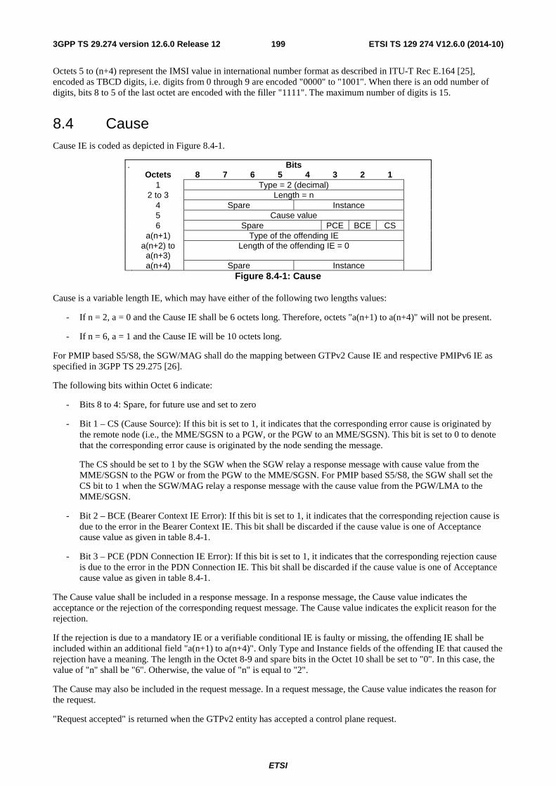
ETSI
ETSI TS 129 274 V12.6.0 (2014-10)1993GPP TS 29.274 version 12.6.0 Release 12
Octets 5 to (n+4) represent the IMSI value in international number format as described in ITU-T Rec E.164 [25], encoded as TBCD digits, i.e. digits from 0 through 9 are encoded "0000" to "1001". When there is an odd number of digits, bits 8 to 5 of the last octet are encoded with the filler "1111". The maximum number of digits is 15.
8.4 Cause Cause IE is coded as depicted in Figure 8.4-1.
. Bits Octets 8 7 6 5 4 3 2 1 1 Type = 2 (decimal) 2 to 3 Length = n 4 Spare Instance 5 Cause value 6 Spare PCE BCE CS a(n+1) Type of the offending IE a(n+2) to
a(n+3) Length of the offending IE = 0
a(n+4) Spare Instance
Figure 8.4-1: Cause
Cause is a variable length IE, which may have either of the following two lengths values:
- If n = 2, a = 0 and the Cause IE shall be 6 octets long. Therefore, octets "a(n+1) to a(n+4)" will not be present.
- If n = 6, a = 1 and the Cause IE will be 10 octets long.
For PMIP based S5/S8, the SGW/MAG shall do the mapping between GTPv2 Cause IE and respective PMIPv6 IE as specified in 3GPP TS 29.275 [26].
The following bits within Octet 6 indicate:
- Bits 8 to 4: Spare, for future use and set to zero
- Bit 1 – CS (Cause Source): If this bit is set to 1, it indicates that the corresponding error cause is originated by the remote node (i.e., the MME/SGSN to a PGW, or the PGW to an MME/SGSN). This bit is set to 0 to denote that the corresponding error cause is originated by the node sending the message.
The CS should be set to 1 by the SGW when the SGW relay a response message with cause value from the MME/SGSN to the PGW or from the PGW to the MME/SGSN. For PMIP based S5/S8, the SGW shall set the CS bit to 1 when the SGW/MAG relay a response message with the cause value from the PGW/LMA to the MME/SGSN.
- Bit 2 – BCE (Bearer Context IE Error): If this bit is set to 1, it indicates that the corresponding rejection cause is due to the error in the Bearer Context IE. This bit shall be discarded if the cause value is one of Acceptance cause value as given in table 8.4-1.
- Bit 3 – PCE (PDN Connection IE Error): If this bit is set to 1, it indicates that the corresponding rejection cause is due to the error in the PDN Connection IE. This bit shall be discarded if the cause value is one of Acceptance cause value as given in table 8.4-1.
The Cause value shall be included in a response message. In a response message, the Cause value indicates the acceptance or the rejection of the corresponding request message. The Cause value indicates the explicit reason for the rejection.
If the rejection is due to a mandatory IE or a verifiable conditional IE is faulty or missing, the offending IE shall be included within an additional field "a(n+1) to a(n+4)". Only Type and Instance fields of the offending IE that caused the rejection have a meaning. The length in the Octet 8-9 and spare bits in the Octet 10 shall be set to "0". In this case, the value of "n" shall be "6". Otherwise, the value of "n" is equal to "2".
The Cause may also be included in the request message. In a request message, the Cause value indicates the reason for the request.
"Request accepted" is returned when the GTPv2 entity has accepted a control plane request.

ETSI
ETSI TS 129 274 V12.6.0 (2014-10)2003GPP TS 29.274 version 12.6.0 Release 12
"Context Not Found" is used in the response message by a GTP entity when it receives a message for which it does not have context, e.g. TEID-C or EBI is not known.
"Context Not Found" may also be used by the PGW during UE requested PDN connectivity procedure while non-3GPP to 3GPP handover, if the request corresponds to the handover of the PDN connection which does not exist with the PGW.
"Service not supported" is used by the GTP entity when it receives a message, which corresponds to a feature or a service which is not supported by the node.
"Service denied" is used when the requested service cannot be granted.
"System failure" is used by the GTP entity to indicate a generic error condition.
"No resources available" is used by the GTP entity to indicate the temporary unavailability of the resource(s) to process the received request.
"Semantic error in the TFT operation", "Syntactic error in the TFT operation", "Semantic errors in packet filter(s)", "Syntactic errors in packet filters(s)", "UE context without TFT already activated", "Semantic error in the TAD operation" and "Syntactic error in the TAD operation" are indications of error cases involving TFT(s)/TAD(s) as specified in subclause 7.7.11 in this specification.
"Missing or unknown APN" is used by the PGW when it does not support the Access Point Name, received in Create Session Request message.
"Relocation failure" is used by the target MME/S4-SGSN to indicate the source MME/S4-SGSN that the relocation has failed.
"Denied in RAT" is used by the GTP entity to indicate that the requested service is not accepted in the RAT.
"Preferred PDN type not supported" is used by the PGW to indicate that the PDN type received in the Create Session Request message is not supported by the PGW for the PDN corresponding to the received Access Point Name.
"Protocol type not supported" is used by the SGW to indicate that the S5/S8 protocol type requested by the MME/S4-SGSN is not supported by it.
"UE not responding" is used by the MME/S4-SGSN to indicate that the UE is not responding to the request initiated by the network, e.g. Paging.
"UE refuses" is used by the GTP entity to indicate that the UE, without specifying further detail, rejected the request from the network.
"Unable to page UE" is used by the MME/S4-SGSN to indicate its inability to page the UE, temporarily.
"User authentication failed" is used by the GTP entity to indicate that the request is rejected due to failure in authentication/security procedure.
"APN access denied – no subscription" is used to indicate that the PGW has denied the user access to an APN because a subscription is required, but the subscriber does not have the necessary subscription.
"Remote peer not responding" is used by the SGW for the messages spanning through two interfaces. This cause value is returned by the SGW to the MME/S4-SGSN or PGW in a response message where no response message is received from the PGW or MME/S4-SGSN.
"Collision with network initiated request" is used by the PGW to indicate that the UE-initiated bearer resource allocation/modification request is rejected since the PGW has requested a bearer resource allocation/modification for the same service using a network-initiated procedure.
"Unable to page UE due to Suspension" is used by the MME/S4-SGSN to indicate that the UE has not been paged because the bearers of the UE are in a suspended state.
"APN Restriction type Incompatible with currently active PDN connection" is used by the PGW to indicate that the newly requested PDN connection has APN restriction value that is not compatible with the currently active PDN connection(s)'s APN restriction value(s).

ETSI
ETSI TS 129 274 V12.6.0 (2014-10)2013GPP TS 29.274 version 12.6.0 Release 12
"Invalid peer" is used by the SGW to indicate that currently the UE is being managed by the different node (e.g. MME/S4-SGSN) than the node (e.g. S4-SGSN/MME) which has sent the Delete Session Request message.
"Invalid Reply from remote peer" is used by the SGW for the messages spanning through two interfaces. This cause value is returned by the SGW to the MME/SGSN or PGW in a reply message where the corresponding reply message on S5/S8 or S11/S4 from the PGW or MME/SGSN is not decoded as valid.
"Temporarily rejected due to handover/TAU/RAU procedure in progress" is used by the MME/S4-SGSN for the bearer related procedure initiated by the PGW. When the handover/TAU/RAU with/without SGW change and/or MME/S4-SGSN change is in progress, the MME/S4-SGSN may receive Create / Update / Delete Bearer request message for the bearer creation, modification or deletion initiated by the PGW. If the handover/TAU/RAU procedure results in the SGW and/or MME/S4-SGSN change, then the bearer related procedure cannot be handled temporarily by the MME/S4-SGSN till the handover/TAU/RAU procedure is completed. In that case the MME/S4-SGSN shall reject the bearer related procedure with this rejection cause. This cause is also used to indicate that the Downlink Data Notification message is rejected temporarily due to the mobility procedures with MME or SGSN change in progress as specified in sub-clause 5.3.4.3 in 3GPP TS 23.401 [3].
The usage of "Fallback to GTPv1" is specified in subclause 7.10 "Fallback to GTPv1 mechanism".
- In the PGW initiated bearer deactivation procedure for the default bearer, the PGW may include the Cause IE in the Delete Bearer Request with values "RAT changed from 3GPP to Non-3GPP", "Reactivation requested" or "Reactivation disallowed to APN".
"APN Congestion" is used by the PGW and it indicates that the PGW has detected congestion for the requested APN and performs overload control for that APN which does not allow the PDN connection to be established.
"GTP-C Entity Congestion" is used to indicate that the GTP-C entity has detected node level congestion and performs overload control at the node level, which does not allow the request to be processed.
"UE already re-attached" is used by MME/S4-SGSN for the network triggered service restoration procedure as specified in 3GPP TS 23.007 [17]. The MME/S4-SGSN may send the Downlink Data Notification Acknowledge or Downlink Data Notification Failure Indication with this cause as part of the network triggered service restoration procedure.
"PDP connection inactivity timer expires" is used by the PGW in Delete Bearer Request(s) to indicate that all the bearer(s) for the emergency PDN connection are deleted upon the inactivity timer expiry as specified in 3GPP TS 23.203 [48].
"Network failure" is used by the SGSN or MME in the Delete Session Request to indicate that the message is sent due to a network problem.
"QoS parameter mismatch" is used by the SGSN or MME in the Delete Session Request to indicate that the PDN connection can not be established due to a QoS parameter mismatch.
"MME/SGSN refuses due to VPLMN policy" is used by the MME/SGSN in the VPLMN to indicate to the PGW in the Create Bearer Response or Update Bearer Response that it does not allow the establishment or modification of the bearer due to VPLMN operator's policy.
The listed cause values for rejection response message descriptions in clause 7 are not meant to be exhaustive lists. Therefore a GTPv2 node shall use the most appropriate matching rejection response cause value that is listed in Table 8.4-1.
If a Bearer Resource Command message is related to an established PDN connection for LIPA or for SIPTO at the local network, the LGW shall reject the Bearer Resource Command with the cause value of "Bearer handling not supported".
"Multiple PDN connections for a given APN not allowed" is used by SGW for reply message to the MME/S4-SGSN when PMIP-based S5/S8 is used. If either SGW or PGW does not support the multiple PDN connections to the same APN function, the SGW shall reject the PDN connectivity request procedure with this rejection cause when receiving Create Session Request for additional PDN connectivity to the given APN from the same UE.
As specified in sub-clause 5.3.1.1 in 3GPP TS 23.401 [3] and sub-clause 9.2.1 in 3GPP TS 23.060 [35], the cause value "New PDN type due to network preference" indicates that the UE has requested PDN type IPv4v6 and only IPv4 or IPv6 address is allowed for the PDN based on PGW operator policy.
ETSI
ETSI TS 129 274 V12.6.0 (2014-10)2023GPP TS 29.274 version 12.6.0 Release 12
As specified in sub-clause 5.3.1.1 in 3GPP TS 23.401 [3] and sub-clause 9.2.1 in 3GPP TS 23.060 [35], the cause value "New PDN type due to single address bearer only" indicates that the MS has requested PDN type IPv4v6 and both IPv4 and IPv6 addressing is possible in the PDN but the Dual Address Bearer Flag of the Indication IE is set to 0 or the Indication IE is absent, or only single IP version addressing is possible in the PDN.
"PGW not responding" is used by the SGW in PGW Restart Notification to indicate that the peer PGW has failed and not restarted as specified in subclause 7.9.5.
"UE context without TFT already activated" is used by the PGW in the Bearer Resource Failure Indication message to indicate that the PGW has received the Bearer Resource Command message without TAD IE in the secondary PDP Context Activation procedure.
"Target access restricted for the subscriber" is used by the MME/SGSN in the Context Response message to indicate that the target access is prohibited for the subscriber, based on the subscription profile.
"P-TMSI Signature mismatch" is used by the SGSN or MME in the Identification Response and Context Response message if the P-TMSI Signature stored in the old SGSN or MME does not match the value sent by the UE via the new SGSN or MME.
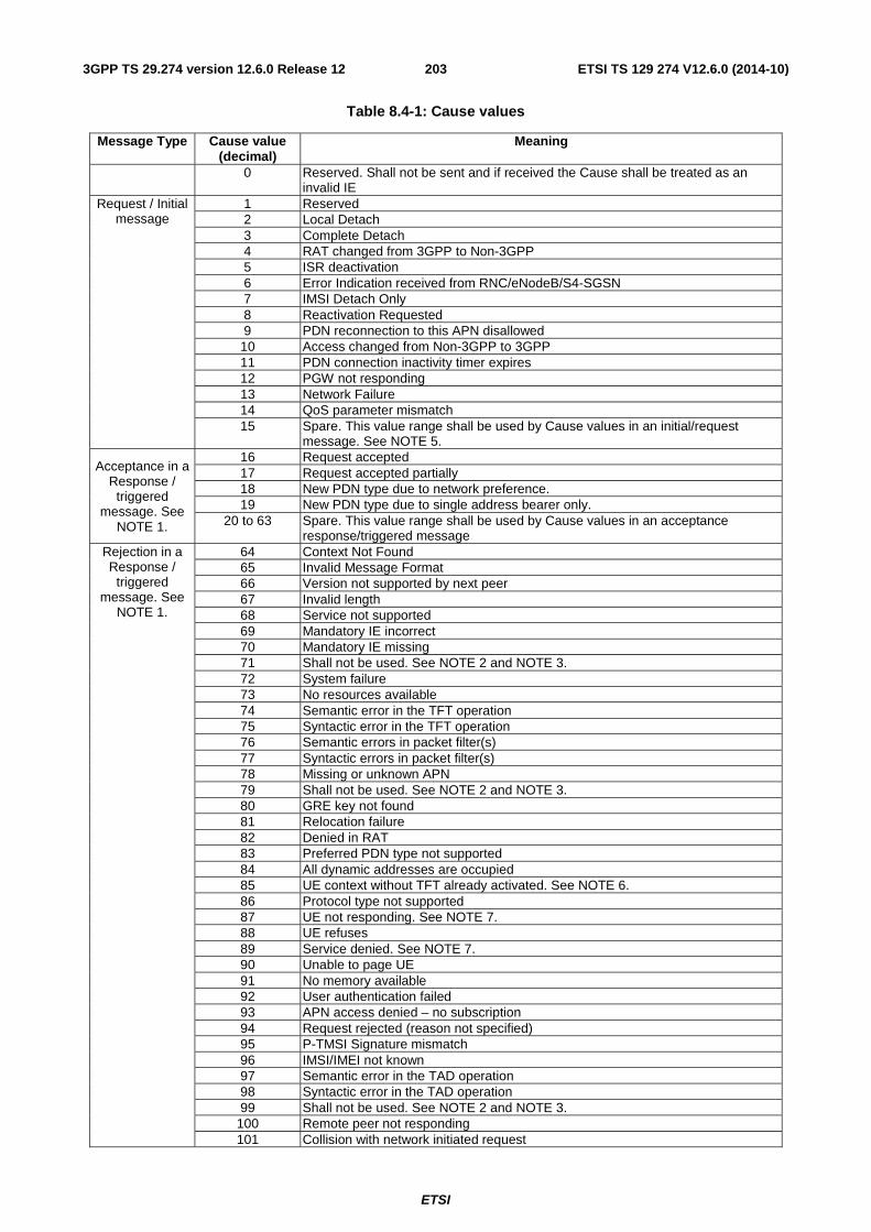
ETSI
ETSI TS 129 274 V12.6.0 (2014-10)2033GPP TS 29.274 version 12.6.0 Release 12
Table 8.4-1: Cause values
Message Type Cause value (decimal)
Meaning
0 Reserved. Shall not be sent and if received the Cause shall be treated as an invalid IE
Request / Initial message
1 Reserved 2 Local Detach 3 Complete Detach 4 RAT changed from 3GPP to Non-3GPP 5 ISR deactivation 6 Error Indication received from RNC/eNodeB/S4-SGSN 7 IMSI Detach Only 8 Reactivation Requested 9 PDN reconnection to this APN disallowed 10 Access changed from Non-3GPP to 3GPP 11 PDN connection inactivity timer expires 12 PGW not responding 13 Network Failure 14 QoS parameter mismatch 15 Spare. This value range shall be used by Cause values in an initial/request
message. See NOTE 5.
Acceptance in a Response /
triggered message. See
NOTE 1.
16 Request accepted 17 Request accepted partially 18 New PDN type due to network preference. 19 New PDN type due to single address bearer only.
20 to 63 Spare. This value range shall be used by Cause values in an acceptance response/triggered message
Rejection in a Response /
triggered message. See
NOTE 1.
64 Context Not Found 65 Invalid Message Format 66 Version not supported by next peer 67 Invalid length 68 Service not supported 69 Mandatory IE incorrect 70 Mandatory IE missing 71 Shall not be used. See NOTE 2 and NOTE 3. 72 System failure 73 No resources available 74 Semantic error in the TFT operation 75 Syntactic error in the TFT operation 76 Semantic errors in packet filter(s) 77 Syntactic errors in packet filter(s) 78 Missing or unknown APN 79 Shall not be used. See NOTE 2 and NOTE 3. 80 GRE key not found 81 Relocation failure 82 Denied in RAT 83 Preferred PDN type not supported 84 All dynamic addresses are occupied 85 UE context without TFT already activated. See NOTE 6. 86 Protocol type not supported 87 UE not responding. See NOTE 7. 88 UE refuses 89 Service denied. See NOTE 7. 90 Unable to page UE 91 No memory available 92 User authentication failed 93 APN access denied – no subscription 94 Request rejected (reason not specified) 95 P-TMSI Signature mismatch 96 IMSI/IMEI not known 97 Semantic error in the TAD operation 98 Syntactic error in the TAD operation 99 Shall not be used. See NOTE 2 and NOTE 3.
100 Remote peer not responding 101 Collision with network initiated request
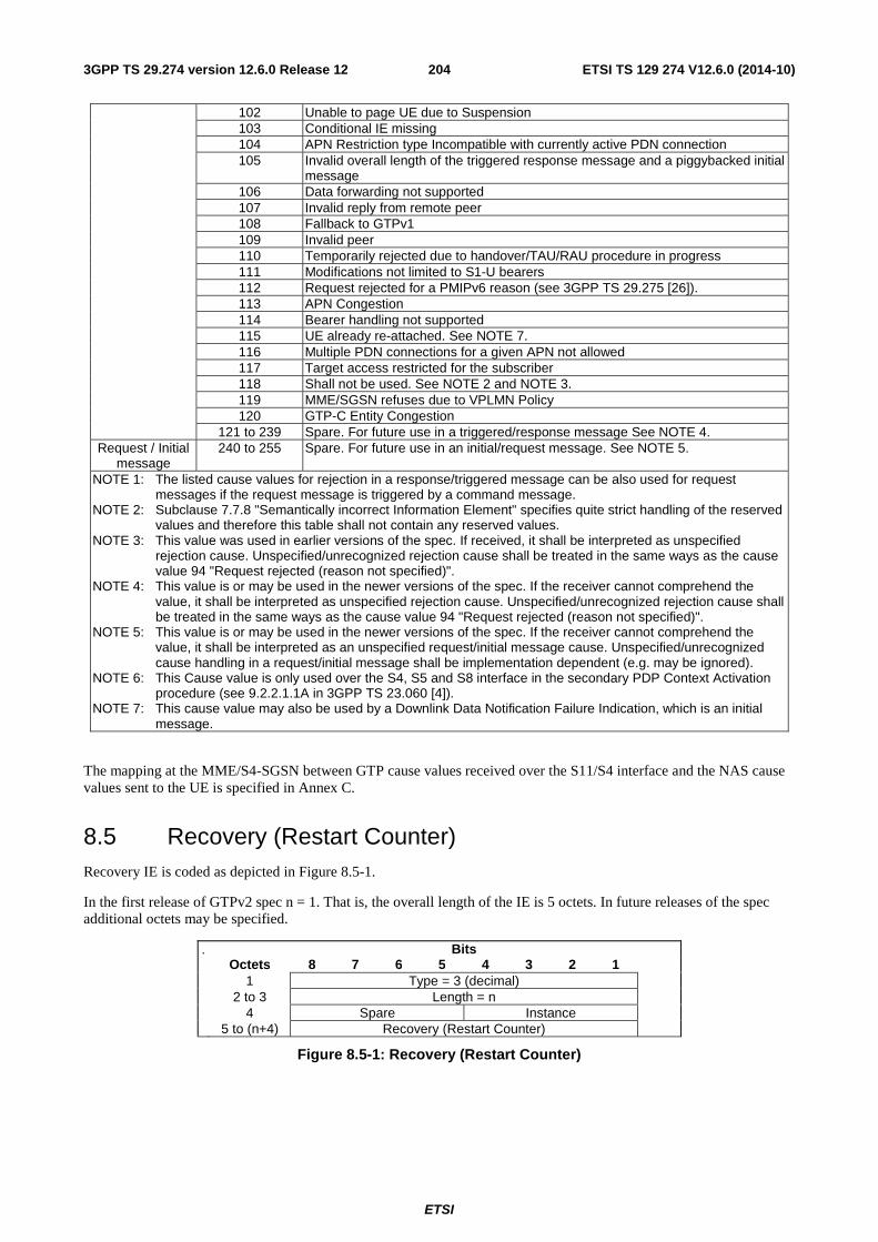
ETSI
ETSI TS 129 274 V12.6.0 (2014-10)2043GPP TS 29.274 version 12.6.0 Release 12
102 Unable to page UE due to Suspension 103 Conditional IE missing 104 APN Restriction type Incompatible with currently active PDN connection 105 Invalid overall length of the triggered response message and a piggybacked initial
message 106 Data forwarding not supported 107 Invalid reply from remote peer 108 Fallback to GTPv1 109 Invalid peer 110 Temporarily rejected due to handover/TAU/RAU procedure in progress 111 Modifications not limited to S1-U bearers 112 Request rejected for a PMIPv6 reason (see 3GPP TS 29.275 [26]). 113 APN Congestion 114 Bearer handling not supported 115 UE already re-attached. See NOTE 7. 116 Multiple PDN connections for a given APN not allowed 117 Target access restricted for the subscriber 118 Shall not be used. See NOTE 2 and NOTE 3. 119 MME/SGSN refuses due to VPLMN Policy 120 GTP-C Entity Congestion
121 to 239 Spare. For future use in a triggered/response message See NOTE 4. Request / Initial
message 240 to 255 Spare. For future use in an initial/request message. See NOTE 5.
NOTE 1: The listed cause values for rejection in a response/triggered message can be also used for request messages if the request message is triggered by a command message.
NOTE 2: Subclause 7.7.8 "Semantically incorrect Information Element" specifies quite strict handling of the reserved values and therefore this table shall not contain any reserved values.
NOTE 3: This value was used in earlier versions of the spec. If received, it shall be interpreted as unspecified rejection cause. Unspecified/unrecognized rejection cause shall be treated in the same ways as the cause value 94 "Request rejected (reason not specified)".
NOTE 4: This value is or may be used in the newer versions of the spec. If the receiver cannot comprehend the value, it shall be interpreted as unspecified rejection cause. Unspecified/unrecognized rejection cause shall be treated in the same ways as the cause value 94 "Request rejected (reason not specified)".
NOTE 5: This value is or may be used in the newer versions of the spec. If the receiver cannot comprehend the value, it shall be interpreted as an unspecified request/initial message cause. Unspecified/unrecognized cause handling in a request/initial message shall be implementation dependent (e.g. may be ignored).
NOTE 6: This Cause value is only used over the S4, S5 and S8 interface in the secondary PDP Context Activation procedure (see 9.2.2.1.1A in 3GPP TS 23.060 [4]).
NOTE 7: This cause value may also be used by a Downlink Data Notification Failure Indication, which is an initial message.
The mapping at the MME/S4-SGSN between GTP cause values received over the S11/S4 interface and the NAS cause values sent to the UE is specified in Annex C.
8.5 Recovery (Restart Counter) Recovery IE is coded as depicted in Figure 8.5-1.
In the first release of GTPv2 spec n = 1. That is, the overall length of the IE is 5 octets. In future releases of the spec additional octets may be specified.
. Bits Octets 8 7 6 5 4 3 2 1 1 Type = 3 (decimal) 2 to 3 Length = n 4 Spare Instance 5 to (n+4) Recovery (Restart Counter)
Figure 8.5-1: Recovery (Restart Counter)
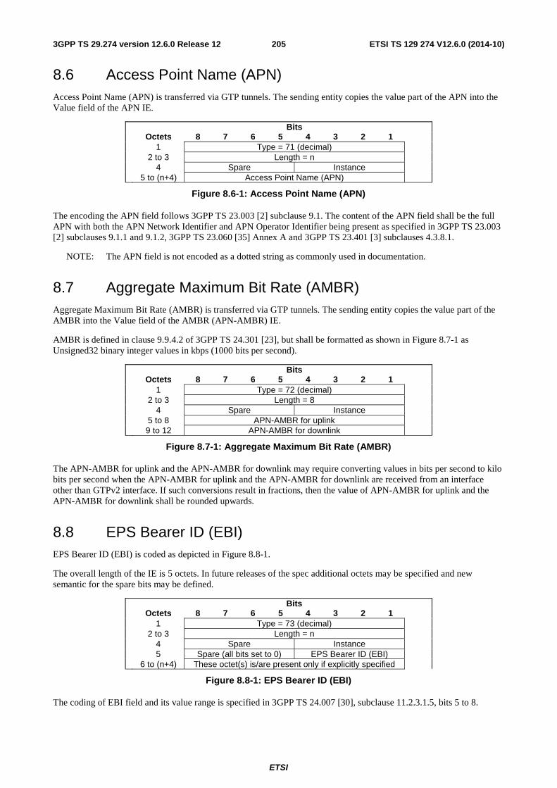
ETSI
ETSI TS 129 274 V12.6.0 (2014-10)2053GPP TS 29.274 version 12.6.0 Release 12
8.6 Access Point Name (APN) Access Point Name (APN) is transferred via GTP tunnels. The sending entity copies the value part of the APN into the Value field of the APN IE.
Bits Octets 8 7 6 5 4 3 2 1 1 Type = 71 (decimal) 2 to 3 Length = n 4 Spare Instance 5 to (n+4) Access Point Name (APN)
Figure 8.6-1: Access Point Name (APN)
The encoding the APN field follows 3GPP TS 23.003 [2] subclause 9.1. The content of the APN field shall be the full APN with both the APN Network Identifier and APN Operator Identifier being present as specified in 3GPP TS 23.003 [2] subclauses 9.1.1 and 9.1.2, 3GPP TS 23.060 [35] Annex A and 3GPP TS 23.401 [3] subclauses 4.3.8.1.
NOTE: The APN field is not encoded as a dotted string as commonly used in documentation.
8.7 Aggregate Maximum Bit Rate (AMBR) Aggregate Maximum Bit Rate (AMBR) is transferred via GTP tunnels. The sending entity copies the value part of the AMBR into the Value field of the AMBR (APN-AMBR) IE.
AMBR is defined in clause 9.9.4.2 of 3GPP TS 24.301 [23], but shall be formatted as shown in Figure 8.7-1 as Unsigned32 binary integer values in kbps (1000 bits per second).
Bits Octets 8 7 6 5 4 3 2 1 1 Type = 72 (decimal) 2 to 3 Length = 8 4 Spare Instance 5 to 8 APN-AMBR for uplink 9 to 12 APN-AMBR for downlink
Figure 8.7-1: Aggregate Maximum Bit Rate (AMBR)
The APN-AMBR for uplink and the APN-AMBR for downlink may require converting values in bits per second to kilo bits per second when the APN-AMBR for uplink and the APN-AMBR for downlink are received from an interface other than GTPv2 interface. If such conversions result in fractions, then the value of APN-AMBR for uplink and the APN-AMBR for downlink shall be rounded upwards.
8.8 EPS Bearer ID (EBI) EPS Bearer ID (EBI) is coded as depicted in Figure 8.8-1.
The overall length of the IE is 5 octets. In future releases of the spec additional octets may be specified and new semantic for the spare bits may be defined.
Bits Octets 8 7 6 5 4 3 2 1 1 Type = 73 (decimal) 2 to 3 Length = n 4 Spare Instance 5 Spare (all bits set to 0) EPS Bearer ID (EBI) 6 to (n+4) These octet(s) is/are present only if explicitly specified
Figure 8.8-1: EPS Bearer ID (EBI)
The coding of EBI field and its value range is specified in 3GPP TS 24.007 [30], subclause 11.2.3.1.5, bits 5 to 8.
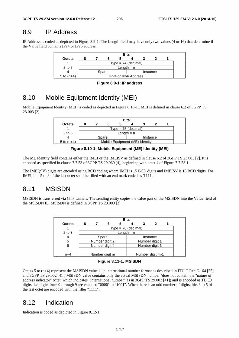
ETSI
ETSI TS 129 274 V12.6.0 (2014-10)2063GPP TS 29.274 version 12.6.0 Release 12
8.9 IP Address IP Address is coded as depicted in Figure 8.9-1. The Length field may have only two values (4 or 16) that determine if the Value field contains IPv4 or IPv6 address.
Bits Octets 8 7 6 5 4 3 2 1 1 Type = 74 (decimal) 2 to 3 Length = n 4 Spare Instance 5 to (n+4) IPv4 or IPv6 Address
Figure 8.9-1: IP address
8.10 Mobile Equipment Identity (MEI) Mobile Equipment Identity (MEI) is coded as depicted in Figure 8.10-1.. MEI is defined in clause 6.2 of 3GPP TS 23.003 [2].
Bits Octets 8 7 6 5 4 3 2 1 1 Type = 75 (decimal) 2 to 3 Length = n 4 Spare Instance 5 to (n+4) Mobile Equipment (ME) Identity
Figure 8.10-1: Mobile Equipment (ME) Identity (MEI)
The ME Identity field contains either the IMEI or the IMEISV as defined in clause 6.2 of 3GPP TS 23.003 [2]. It is encoded as specified in clause 7.7.53 of 3GPP TS 29.060 [4], beginning with octet 4 of Figure 7.7.53.1.
The IMEI(SV) digits are encoded using BCD coding where IMEI is 15 BCD digits and IMEISV is 16 BCD digits. For IMEI, bits 5 to 8 of the last octet shall be filled with an end mark coded as '1111'.
8.11 MSISDN MSISDN is transferred via GTP tunnels. The sending entity copies the value part of the MSISDN into the Value field of the MSISDN IE. MSISDN is defined in 3GPP TS 23.003 [2].
Bits Octets 8 7 6 5 4 3 2 1 1 Type = 76 (decimal) 2 to 3 Length = n 4 Spare Instance 5 Number digit 2 Number digit 1 6 Number digit 4 Number digit 3 … … … n+4 Number digit m Number digit m-1
Figure 8.11-1: MSISDN
Octets 5 to (n+4) represent the MSISDN value is in international number format as described in ITU-T Rec E.164 [25] and 3GPP TS 29.002 [41]. MSISDN value contains only the actual MSISDN number (does not contain the "nature of address indicator" octet, which indicates "international number" as in 3GPP TS 29.002 [41]) and is encoded as TBCD digits, i.e. digits from 0 through 9 are encoded "0000" to "1001". When there is an odd number of digits, bits 8 to 5 of the last octet are encoded with the filler "1111".
8.12 Indication Indication is coded as depicted in Figure 8.12-1.
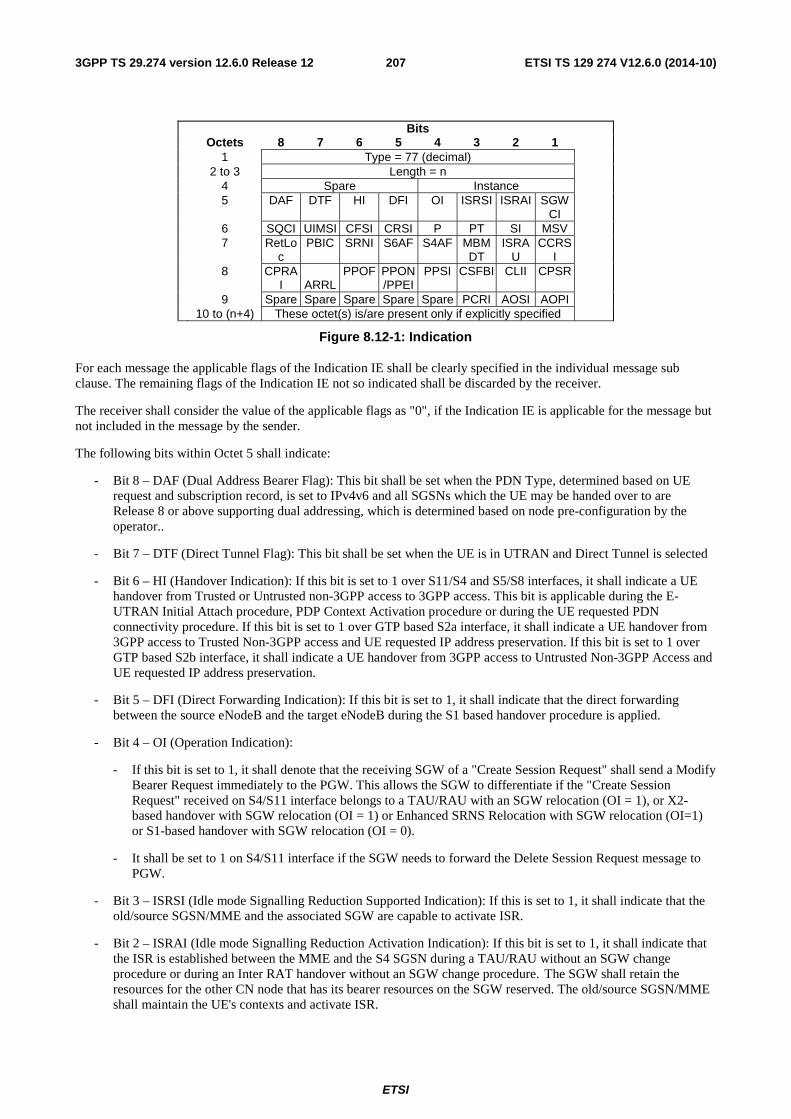
ETSI
ETSI TS 129 274 V12.6.0 (2014-10)2073GPP TS 29.274 version 12.6.0 Release 12
Bits Octets 8 7 6 5 4 3 2 1 1 Type = 77 (decimal) 2 to 3 Length = n 4 Spare Instance 5 DAF DTF HI DFI OI ISRSI ISRAI SGW
CI
6 SQCI UIMSI CFSI CRSI P PT SI MSV 7 RetLo
c PBIC SRNI S6AF S4AF MBM
DT ISRA
U CCRS
I
8 CPRAI
ARRL
PPOF PPON/PPEI
PPSI CSFBI CLII CPSR
9 Spare Spare Spare Spare Spare PCRI AOSI AOPI 10 to (n+4) These octet(s) is/are present only if explicitly specified
Figure 8.12-1: Indication
For each message the applicable flags of the Indication IE shall be clearly specified in the individual message sub clause. The remaining flags of the Indication IE not so indicated shall be discarded by the receiver.
The receiver shall consider the value of the applicable flags as "0", if the Indication IE is applicable for the message but not included in the message by the sender.
The following bits within Octet 5 shall indicate:
- Bit 8 – DAF (Dual Address Bearer Flag): This bit shall be set when the PDN Type, determined based on UE request and subscription record, is set to IPv4v6 and all SGSNs which the UE may be handed over to are Release 8 or above supporting dual addressing, which is determined based on node pre-configuration by the operator..
- Bit 7 – DTF (Direct Tunnel Flag): This bit shall be set when the UE is in UTRAN and Direct Tunnel is selected
- Bit 6 – HI (Handover Indication): If this bit is set to 1 over S11/S4 and S5/S8 interfaces, it shall indicate a UE handover from Trusted or Untrusted non-3GPP access to 3GPP access. This bit is applicable during the E-UTRAN Initial Attach procedure, PDP Context Activation procedure or during the UE requested PDN connectivity procedure. If this bit is set to 1 over GTP based S2a interface, it shall indicate a UE handover from 3GPP access to Trusted Non-3GPP access and UE requested IP address preservation. If this bit is set to 1 over GTP based S2b interface, it shall indicate a UE handover from 3GPP access to Untrusted Non-3GPP Access and UE requested IP address preservation.
- Bit 5 – DFI (Direct Forwarding Indication): If this bit is set to 1, it shall indicate that the direct forwarding between the source eNodeB and the target eNodeB during the S1 based handover procedure is applied.
- Bit 4 – OI (Operation Indication):
- If this bit is set to 1, it shall denote that the receiving SGW of a "Create Session Request" shall send a Modify Bearer Request immediately to the PGW. This allows the SGW to differentiate if the "Create Session Request" received on S4/S11 interface belongs to a TAU/RAU with an SGW relocation (OI = 1), or X2-based handover with SGW relocation (OI = 1) or Enhanced SRNS Relocation with SGW relocation (OI=1) or S1-based handover with SGW relocation (OI = 0).
- It shall be set to 1 on S4/S11 interface if the SGW needs to forward the Delete Session Request message to PGW.
- Bit 3 – ISRSI (Idle mode Signalling Reduction Supported Indication): If this is set to 1, it shall indicate that the old/source SGSN/MME and the associated SGW are capable to activate ISR.
- Bit 2 – ISRAI (Idle mode Signalling Reduction Activation Indication): If this bit is set to 1, it shall indicate that the ISR is established between the MME and the S4 SGSN during a TAU/RAU without an SGW change procedure or during an Inter RAT handover without an SGW change procedure. The SGW shall retain the resources for the other CN node that has its bearer resources on the SGW reserved. The old/source SGSN/MME shall maintain the UE's contexts and activate ISR.
ETSI
ETSI TS 129 274 V12.6.0 (2014-10)2083GPP TS 29.274 version 12.6.0 Release 12
- Bit 1 – SGWCI (SGW Change Indication): If this bit is set to 1, it shall indicate that the target MME/SGSN has selected a new SGW during a TAU/RAU or handover with an SGW change procedure.
The following bits within Octet 6 shall indicate:
- Bit 8 – SQCI (Subscribed QoS Change Indication): If this bit is set to 1, it indicates that the subscribed QoS profile of the related PDN connection has changed in the old MME/SGSN when the UE is in ECM-IDLE state and ISR is activated. The new MME/SGSN shall trigger the Subscribed QoS Modification procedure. See 3GPP TS 23.401 [3], clause 5.3.9.2.
- Bit 7 – UIMSI (Unauthenticated IMSI): If this bit is set to 1, it indicates that the IMSI present in the message is not authenticated and is for emergency attached UE.
- Bit 6 – CFSI (Change F-TEID support indication): if this bit is set to 1, it indicates that the SGW can change the assigned GTP-U F-TEID in the current procedure. If the SGW needs to modify the GTP-U F-TEID and the CFSI flag is set to 1 in the corresponding request message, the SGW shall include the new F-TEID in the Modify Bearer Response/Modify Access Bearers Response message.
- Bit 5 – CRSI (Change Reporting support indication): if this bit is set to 1, it indicates that the MME/S4 SGSN supports Location Change Reporting mechanism for the corresponding session.
- Bit 4 – PS (Piggybacking Supported). This bit denotes whether the MME/SGW support piggybacking feature as described in Annex F of 3GPP TS 23.401 [3]. If set to 1, it indicates that the node is capable of processing two different GTP-C messages appearing back to back in a single UDP payload.
- Bit 3 – PT (Protocol Type) If this bit set to 1, it shall indicate that the protocol type for the S5/S8 interface is PMIP; this bit is set to 0 to indicate that the protocol type for the S5/S8 interface is GTP.
- Bit 2 – SI (Scope Indication): If this bit is set to 1, it indicates that all bearer resources of the UE shall be released by the SGW. This flag is set in messages during TAU/RAU/Handover with SGW change /SRNS Relocation Cancel Using S4 with SGW change/Inter RAT handover Cancel procedure with SGW change/S1 Based handover Cancel procedure with SGW change.
- Bit 1 – MSV (MS Validated): If this bit is set to 1, it shall indicate that the new MME/SGSN has successfully authenticated the UE.
The following bits within Octet 7shall indicate:
- Bit 8 – RetLoc (Retrieve Location Indication Flag): if this bit is set to 1, it indicates that the PGW requests the MME/SGSN to provide the User Location Information.
Bit 7 – PBIC (Propagate BBAI Information Change): if this bit is set to 1, it indicates a change in the H(e)NB local IP address and/or UDP port number, i.e. the UE moves from an (e)NB to a H(e)NB, or from one H(e)NB to another H(e)NB with the fixed network backhaul changed, or the UE moves from a H(e)NB to a (e)NB.
- Bit 6 – SRNI (SGW Restoration Needed Indication): if this bit is set to 1, it indicates that the source MME/S4-SGSN has not performed the SGW relocation procedure after the source SGW has failed with or without restart, when the source and target MME/S4-SGSN support the MME/S4-SGSN triggered SGW restoration procedure as specified in 3GPP TS 23.007 [17].
- Bit 5 – S6AF (Static IPv6 Address Flag): if this bit is set to 1, it indicates that PDP/PDN IPv6 address is static.
- Bit 4 – S4AF (Static IPv4 Address Flag): if this bit is set to 1, it indicates that PDP/PDN IPv4 address is static.
- Bit 3 – MBMDT (Management Based MDT allowed flag): if this bit is set to 1, it indicates that management based MDT is allowed.
- Bit 2 – ISRAU (ISR is activated for the UE): if this bit is set to 1, it indicates that ISR is activated for the UE before the UE moving to the new SGSN/MME.
- Bit 1 – CCRSI (CSG Change Reporting support indication): if this bit is set to 1, it indicates that the MME/S4 SGSN supports CSG Information Change Reporting mechanism for the corresponding session.
The following bits within Octet 8 shall indicate:
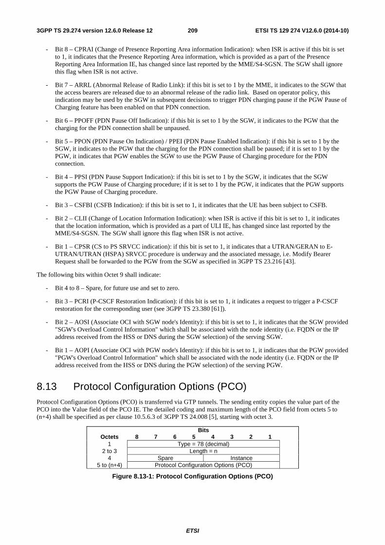
ETSI
ETSI TS 129 274 V12.6.0 (2014-10)2093GPP TS 29.274 version 12.6.0 Release 12
- Bit 8 – CPRAI (Change of Presence Reporting Area information Indication): when ISR is active if this bit is set to 1, it indicates that the Presence Reporting Area information, which is provided as a part of the Presence Reporting Area Information IE, has changed since last reported by the MME/S4-SGSN. The SGW shall ignore this flag when ISR is not active.
- Bit 7 – ARRL (Abnormal Release of Radio Link): if this bit is set to 1 by the MME, it indicates to the SGW that the access bearers are released due to an abnormal release of the radio link. Based on operator policy, this indication may be used by the SGW in subsequent decisions to trigger PDN charging pause if the PGW Pause of Charging feature has been enabled on that PDN connection.
- Bit 6 – PPOFF (PDN Pause Off Indication): if this bit is set to 1 by the SGW, it indicates to the PGW that the charging for the PDN connection shall be unpaused.
- Bit 5 – PPON (PDN Pause On Indication) / PPEI (PDN Pause Enabled Indication): if this bit is set to 1 by the SGW, it indicates to the PGW that the charging for the PDN connection shall be paused; if it is set to 1 by the PGW, it indicates that PGW enables the SGW to use the PGW Pause of Charging procedure for the PDN connection.
- Bit 4 – PPSI (PDN Pause Support Indication): if this bit is set to 1 by the SGW, it indicates that the SGW supports the PGW Pause of Charging procedure; if it is set to 1 by the PGW, it indicates that the PGW supports the PGW Pause of Charging procedure.
- Bit 3 – CSFBI (CSFB Indication): if this bit is set to 1, it indicates that the UE has been subject to CSFB.
- Bit 2 – CLII (Change of Location Information Indication): when ISR is active if this bit is set to 1, it indicates that the location information, which is provided as a part of ULI IE, has changed since last reported by the MME/S4-SGSN. The SGW shall ignore this flag when ISR is not active.
- Bit 1 – CPSR (CS to PS SRVCC indication): if this bit is set to 1, it indicates that a UTRAN/GERAN to E-UTRAN/UTRAN (HSPA) SRVCC procedure is underway and the associated message, i.e. Modify Bearer Request shall be forwarded to the PGW from the SGW as specified in 3GPP TS 23.216 [43].
The following bits within Octet 9 shall indicate:
- Bit 4 to 8 – Spare, for future use and set to zero.
- Bit 3 – PCRI (P-CSCF Restoration Indication): if this bit is set to 1, it indicates a request to trigger a P-CSCF restoration for the corresponding user (see 3GPP TS 23.380 [61]).
- Bit 2 – AOSI (Associate OCI with SGW node's Identity): if this bit is set to 1, it indicates that the SGW provided "SGW's Overload Control Information" which shall be associated with the node identity (i.e. FQDN or the IP address received from the HSS or DNS during the SGW selection) of the serving SGW.
- Bit 1 – AOPI (Associate OCI with PGW node's Identity): if this bit is set to 1, it indicates that the PGW provided "PGW's Overload Control Information" which shall be associated with the node identity (i.e. FQDN or the IP address received from the HSS or DNS during the PGW selection) of the serving PGW.
8.13 Protocol Configuration Options (PCO) Protocol Configuration Options (PCO) is transferred via GTP tunnels. The sending entity copies the value part of the PCO into the Value field of the PCO IE. The detailed coding and maximum length of the PCO field from octets 5 to (n+4) shall be specified as per clause 10.5.6.3 of 3GPP TS 24.008 [5], starting with octet 3.
Bits Octets 8 7 6 5 4 3 2 1 1 Type = 78 (decimal) 2 to 3 Length = n 4 Spare Instance 5 to (n+4) Protocol Configuration Options (PCO)
Figure 8.13-1: Protocol Configuration Options (PCO)
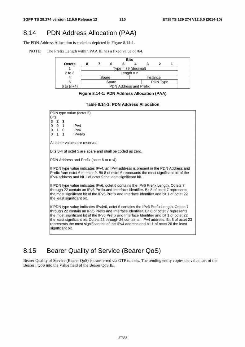
ETSI
ETSI TS 129 274 V12.6.0 (2014-10)2103GPP TS 29.274 version 12.6.0 Release 12
8.14 PDN Address Allocation (PAA) The PDN Address Allocation is coded as depicted in Figure 8.14-1.
NOTE: The Prefix Length within PAA IE has a fixed value of /64.
Bits Octets 8 7 6 5 4 3 2 1 1 Type = 79 (decimal) 2 to 3 Length = n 4 Spare Instance 5 Spare PDN Type 6 to (n+4) PDN Address and Prefix
Figure 8.14-1: PDN Address Allocation (PAA)
Table 8.14-1: PDN Address Allocation
PDN type value (octet 5) Bits 3 2 1 0 0 1 IPv4 0 1 0 IPv6 0 1 1 IPv4v6 All other values are reserved. Bits 8-4 of octet 5 are spare and shall be coded as zero. PDN Address and Prefix (octet 6 to n+4) If PDN type value indicates IPv4, an IPv4 address is present in the PDN Address and Prefix from octet 6 to octet 9. Bit 8 of octet 6 represents the most significant bit of the IPv4 address and bit 1 of octet 9 the least significant bit. If PDN type value indicates IPv6, octet 6 contains the IPv6 Prefix Length. Octets 7 through 22 contain an IPv6 Prefix and Interface Identifier. Bit 8 of octet 7 represents the most significant bit of the IPv6 Prefix and Interface Identifier and bit 1 of octet 22 the least significant bit. If PDN type value indicates IPv4v6, octet 6 contains the IPv6 Prefix Length. Octets 7 through 22 contain an IPv6 Prefix and Interface Identifier. Bit 8 of octet 7 represents the most significant bit of the IPv6 Prefix and Interface Identifier and bit 1 of octet 22 the least significant bit. Octets 23 through 26 contain an IPv4 address. Bit 8 of octet 23 represents the most significant bit of the IPv4 address and bit 1 of octet 26 the least significant bit.
8.15 Bearer Quality of Service (Bearer QoS) Bearer Quality of Service (Bearer QoS) is transferred via GTP tunnels. The sending entity copies the value part of the Bearer l QoS into the Value field of the Bearer QoS IE.
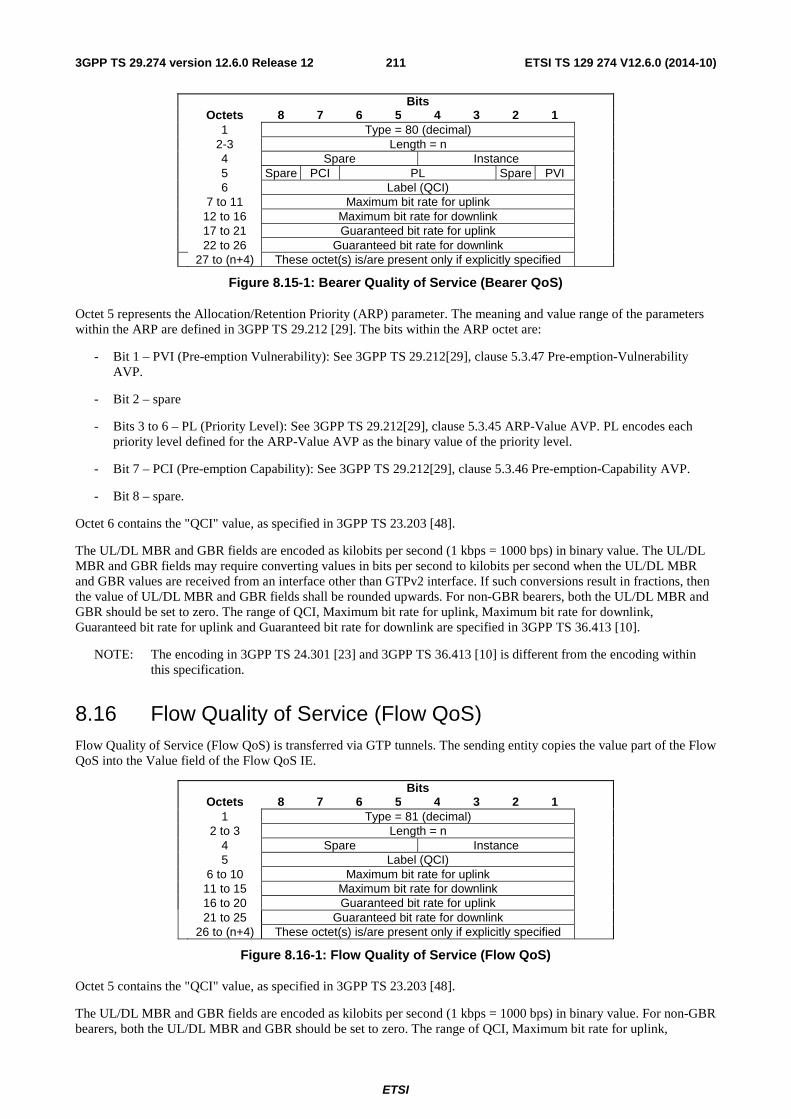
ETSI
ETSI TS 129 274 V12.6.0 (2014-10)2113GPP TS 29.274 version 12.6.0 Release 12
Bits Octets 8 7 6 5 4 3 2 1 1 Type = 80 (decimal) 2-3 Length = n 4 Spare Instance 5 Spare PCI PL Spare PVI 6 Label (QCI) 7 to 11 Maximum bit rate for uplink 12 to 16 Maximum bit rate for downlink 17 to 21 Guaranteed bit rate for uplink 22 to 26 Guaranteed bit rate for downlink 27 to (n+4) These octet(s) is/are present only if explicitly specified
Figure 8.15-1: Bearer Quality of Service (Bearer QoS)
Octet 5 represents the Allocation/Retention Priority (ARP) parameter. The meaning and value range of the parameters within the ARP are defined in 3GPP TS 29.212 [29]. The bits within the ARP octet are:
- Bit 1 – PVI (Pre-emption Vulnerability): See 3GPP TS 29.212[29], clause 5.3.47 Pre-emption-Vulnerability AVP.
- Bit 2 – spare
- Bits 3 to 6 – PL (Priority Level): See 3GPP TS 29.212[29], clause 5.3.45 ARP-Value AVP. PL encodes each priority level defined for the ARP-Value AVP as the binary value of the priority level.
- Bit 7 – PCI (Pre-emption Capability): See 3GPP TS 29.212[29], clause 5.3.46 Pre-emption-Capability AVP.
- Bit 8 – spare.
Octet 6 contains the "QCI" value, as specified in 3GPP TS 23.203 [48].
The UL/DL MBR and GBR fields are encoded as kilobits per second (1 kbps = 1000 bps) in binary value. The UL/DL MBR and GBR fields may require converting values in bits per second to kilobits per second when the UL/DL MBR and GBR values are received from an interface other than GTPv2 interface. If such conversions result in fractions, then the value of UL/DL MBR and GBR fields shall be rounded upwards. For non-GBR bearers, both the UL/DL MBR and GBR should be set to zero. The range of QCI, Maximum bit rate for uplink, Maximum bit rate for downlink, Guaranteed bit rate for uplink and Guaranteed bit rate for downlink are specified in 3GPP TS 36.413 [10].
NOTE: The encoding in 3GPP TS 24.301 [23] and 3GPP TS 36.413 [10] is different from the encoding within this specification.
8.16 Flow Quality of Service (Flow QoS) Flow Quality of Service (Flow QoS) is transferred via GTP tunnels. The sending entity copies the value part of the Flow QoS into the Value field of the Flow QoS IE.
Bits Octets 8 7 6 5 4 3 2 1 1 Type = 81 (decimal) 2 to 3 Length = n 4 Spare Instance 5 Label (QCI) 6 to 10 Maximum bit rate for uplink 11 to 15 Maximum bit rate for downlink 16 to 20 Guaranteed bit rate for uplink 21 to 25 Guaranteed bit rate for downlink 26 to (n+4) These octet(s) is/are present only if explicitly specified
Figure 8.16-1: Flow Quality of Service (Flow QoS)
Octet 5 contains the "QCI" value, as specified in 3GPP TS 23.203 [48].
The UL/DL MBR and GBR fields are encoded as kilobits per second (1 kbps = 1000 bps) in binary value. For non-GBR bearers, both the UL/DL MBR and GBR should be set to zero. The range of QCI, Maximum bit rate for uplink,
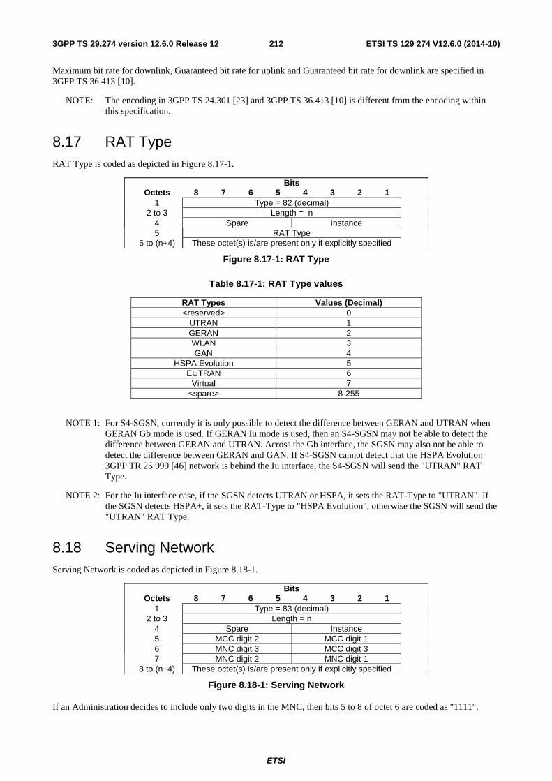
ETSI
ETSI TS 129 274 V12.6.0 (2014-10)2123GPP TS 29.274 version 12.6.0 Release 12
Maximum bit rate for downlink, Guaranteed bit rate for uplink and Guaranteed bit rate for downlink are specified in 3GPP TS 36.413 [10].
NOTE: The encoding in 3GPP TS 24.301 [23] and 3GPP TS 36.413 [10] is different from the encoding within this specification.
8.17 RAT Type RAT Type is coded as depicted in Figure 8.17-1.
Bits Octets 8 7 6 5 4 3 2 1 1 Type = 82 (decimal) 2 to 3 Length = n 4 Spare Instance 5 RAT Type 6 to (n+4) These octet(s) is/are present only if explicitly specified
Figure 8.17-1: RAT Type
Table 8.17-1: RAT Type values
RAT Types Values (Decimal) <reserved> 0
UTRAN 1 GERAN 2 WLAN 3 GAN 4
HSPA Evolution 5 EUTRAN 6
Virtual 7 <spare> 8-255
NOTE 1: For S4-SGSN, currently it is only possible to detect the difference between GERAN and UTRAN when GERAN Gb mode is used. If GERAN Iu mode is used, then an S4-SGSN may not be able to detect the difference between GERAN and UTRAN. Across the Gb interface, the SGSN may also not be able to detect the difference between GERAN and GAN. If S4-SGSN cannot detect that the HSPA Evolution 3GPP TR 25.999 [46] network is behind the Iu interface, the S4-SGSN will send the "UTRAN" RAT Type.
NOTE 2: For the Iu interface case, if the SGSN detects UTRAN or HSPA, it sets the RAT-Type to "UTRAN". If the SGSN detects HSPA+, it sets the RAT-Type to "HSPA Evolution", otherwise the SGSN will send the "UTRAN" RAT Type.
8.18 Serving Network Serving Network is coded as depicted in Figure 8.18-1.
Bits Octets 8 7 6 5 4 3 2 1 1 Type = 83 (decimal) 2 to 3 Length = n 4 Spare Instance 5 MCC digit 2 MCC digit 1 6 MNC digit 3 MCC digit 3 7 MNC digit 2 MNC digit 1 8 to (n+4) These octet(s) is/are present only if explicitly specified
Figure 8.18-1: Serving Network
If an Administration decides to include only two digits in the MNC, then bits 5 to 8 of octet 6 are coded as "1111".
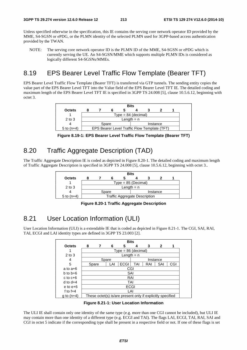
ETSI
ETSI TS 129 274 V12.6.0 (2014-10)2133GPP TS 29.274 version 12.6.0 Release 12
Unless specified otherwise in the specification, this IE contains the serving core network operator ID provided by the MME, S4-SGSN or ePDG, or the PLMN identity of the selected PLMN used for 3GPP-based access authentication provided by the TWAN.
NOTE: The serving core network operator ID is the PLMN ID of the MME, S4-SGSN or ePDG which is currently serving the UE. An S4-SGSN/MME which supports multiple PLMN IDs is considered as logically different S4-SGSNs/MMEs.
8.19 EPS Bearer Level Traffic Flow Template (Bearer TFT) EPS Bearer Level Traffic Flow Template (Bearer TFT) is transferred via GTP tunnels. The sending entity copies the value part of the EPS Bearer Level TFT into the Value field of the EPS Bearer Level TFT IE. The detailed coding and maximum length of the EPS Bearer Level TFT IE is specified in 3GPP TS 24.008 [5], clause 10.5.6.12, beginning with octet 3.
Bits Octets 8 7 6 5 4 3 2 1 1 Type = 84 (decimal) 2 to 3 Length = n 4 Spare Instance 5 to (n+4) EPS Bearer Level Traffic Flow Template (TFT)
Figure 8.19-1: EPS Bearer Level Traffic Flow Template (Bearer TFT)
8.20 Traffic Aggregate Description (TAD) The Traffic Aggregate Description IE is coded as depicted in Figure 8.20-1. The detailed coding and maximum length of Traffic Aggregate Description is specified in 3GPP TS 24.008 [5], clause 10.5.6.12, beginning with octet 3..
Bits Octets 8 7 6 5 4 3 2 1 1 Type = 85 (Decimal) 2 to 3 Length = n 4 Spare Instance 5 to (n+4) Traffic Aggregate Description
Figure 8.20-1 Traffic Aggregate Description
8.21 User Location Information (ULI) User Location Information (ULI) is a extendable IE that is coded as depicted in Figure 8.21-1. The CGI, SAI, RAI, TAI, ECGI and LAI identity types are defined in 3GPP TS 23.003 [2].
Bits Octets 8 7 6 5 4 3 2 1 1 Type = 86 (decimal) 2 to 3 Length = n 4 Spare Instance 5 Spare LAI ECGI TAI RAI SAI CGI a to a+6 CGI b to b+6 SAI c to c+6 RAI d to d+4 TAI e to e+6 ECGI f to f+4 LAI g to (n+4) These octet(s) is/are present only if explicitly specified
Figure 8.21-1: User Location Information
The ULI IE shall contain only one identity of the same type (e.g. more than one CGI cannot be included), but ULI IE may contain more than one identity of a different type (e.g. ECGI and TAI). The flags LAI, ECGI, TAI, RAI, SAI and CGI in octet 5 indicate if the corresponding type shall be present in a respective field or not. If one of these flags is set
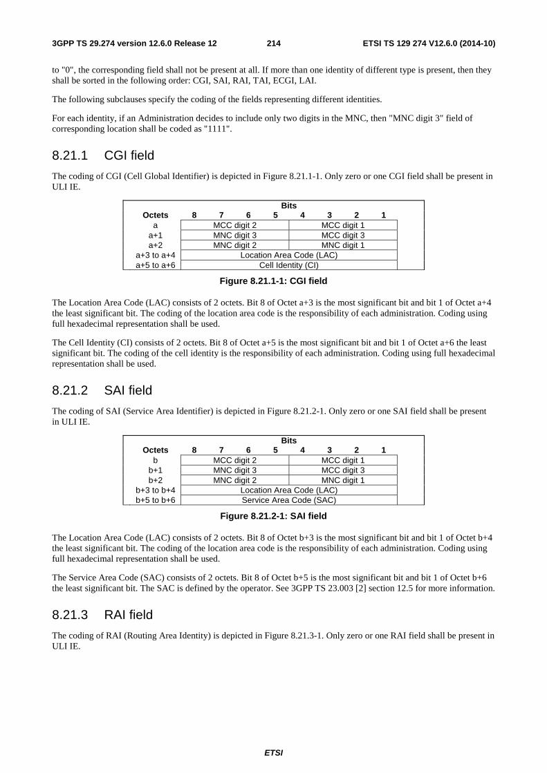
ETSI
ETSI TS 129 274 V12.6.0 (2014-10)2143GPP TS 29.274 version 12.6.0 Release 12
to "0", the corresponding field shall not be present at all. If more than one identity of different type is present, then they shall be sorted in the following order: CGI, SAI, RAI, TAI, ECGI, LAI.
The following subclauses specify the coding of the fields representing different identities.
For each identity, if an Administration decides to include only two digits in the MNC, then "MNC digit 3" field of corresponding location shall be coded as "1111".
8.21.1 CGI field
The coding of CGI (Cell Global Identifier) is depicted in Figure 8.21.1-1. Only zero or one CGI field shall be present in ULI IE.
Bits Octets 8 7 6 5 4 3 2 1 a MCC digit 2 MCC digit 1 a+1 MNC digit 3 MCC digit 3 a+2 MNC digit 2 MNC digit 1 a+3 to a+4 Location Area Code (LAC) a+5 to a+6 Cell Identity (CI)
Figure 8.21.1-1: CGI field
The Location Area Code (LAC) consists of 2 octets. Bit 8 of Octet a+3 is the most significant bit and bit 1 of Octet a+4 the least significant bit. The coding of the location area code is the responsibility of each administration. Coding using full hexadecimal representation shall be used.
The Cell Identity (CI) consists of 2 octets. Bit 8 of Octet a+5 is the most significant bit and bit 1 of Octet a+6 the least significant bit. The coding of the cell identity is the responsibility of each administration. Coding using full hexadecimal representation shall be used.
8.21.2 SAI field
The coding of SAI (Service Area Identifier) is depicted in Figure 8.21.2-1. Only zero or one SAI field shall be present in ULI IE.
Bits Octets 8 7 6 5 4 3 2 1 b MCC digit 2 MCC digit 1 b+1 MNC digit 3 MCC digit 3 b+2 MNC digit 2 MNC digit 1 b+3 to b+4 Location Area Code (LAC) b+5 to b+6 Service Area Code (SAC)
Figure 8.21.2-1: SAI field
The Location Area Code (LAC) consists of 2 octets. Bit 8 of Octet b+3 is the most significant bit and bit 1 of Octet b+4 the least significant bit. The coding of the location area code is the responsibility of each administration. Coding using full hexadecimal representation shall be used.
The Service Area Code (SAC) consists of 2 octets. Bit 8 of Octet b+5 is the most significant bit and bit 1 of Octet b+6 the least significant bit. The SAC is defined by the operator. See 3GPP TS 23.003 [2] section 12.5 for more information.
8.21.3 RAI field
The coding of RAI (Routing Area Identity) is depicted in Figure 8.21.3-1. Only zero or one RAI field shall be present in ULI IE.
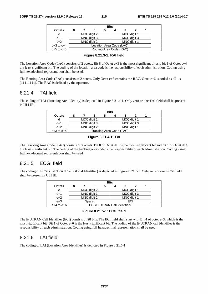
ETSI
ETSI TS 129 274 V12.6.0 (2014-10)2153GPP TS 29.274 version 12.6.0 Release 12
Bits Octets 8 7 6 5 4 3 2 1 c MCC digit 2 MCC digit 1 c+1 MNC digit 3 MCC digit 3 c+2 MNC digit 2 MNC digit 1 c+3 to c+4 Location Area Code (LAC) c+5 to c+6 Routing Area Code (RAC)
Figure 8.21.3-1: RAI field
The Location Area Code (LAC) consists of 2 octets. Bit 8 of Octet c+3 is the most significant bit and bit 1 of Octet c+4 the least significant bit. The coding of the location area code is the responsibility of each administration. Coding using full hexadecimal representation shall be used.
The Routing Area Code (RAC) consists of 2 octets. Only Octet c+5 contains the RAC. Octet c+6 is coded as all 1's (11111111). The RAC is defined by the operator.
8.21.4 TAI field
The coding of TAI (Tracking Area Identity) is depicted in Figure 8.21.4-1. Only zero or one TAI field shall be present in ULI IE.
Bits Octets 8 7 6 5 4 3 2 1 d MCC digit 2 MCC digit 1 d+1 MNC digit 3 MCC digit 3 d+2 MNC digit 2 MNC digit 1 d+3 to d+4 Tracking Area Code (TAC)
Figure 8.21.4-1: TAI
The Tracking Area Code (TAC) consists of 2 octets. Bit 8 of Octet d+3 is the most significant bit and bit 1 of Octet d+4 the least significant bit. The coding of the tracking area code is the responsibility of each administration. Coding using full hexadecimal representation shall be used.
8.21.5 ECGI field
The coding of ECGI (E-UTRAN Cell Global Identifier) is depicted in Figure 8.21.5-1. Only zero or one ECGI field shall be present in ULI IE.
Bits Octets 8 7 6 5 4 3 2 1 e MCC digit 2 MCC digit 1 e+1 MNC digit 3 MCC digit 3 e+2 MNC digit 2 MNC digit 1 e+3 Spare ECI e+4 to e+6 ECI (E-UTRAN Cell Identifier)
Figure 8.21.5-1: ECGI field
The E-UTRAN Cell Identifier (ECI) consists of 28 bits. The ECI field shall start with Bit 4 of octet e+3, which is the most significant bit. Bit 1 of Octet e+6 is the least significant bit. The coding of the E-UTRAN cell identifier is the responsibility of each administration. Coding using full hexadecimal representation shall be used.
8.21.6 LAI field
The coding of LAI (Location Area Identifier) is depicted in Figure 8.21.6-1.
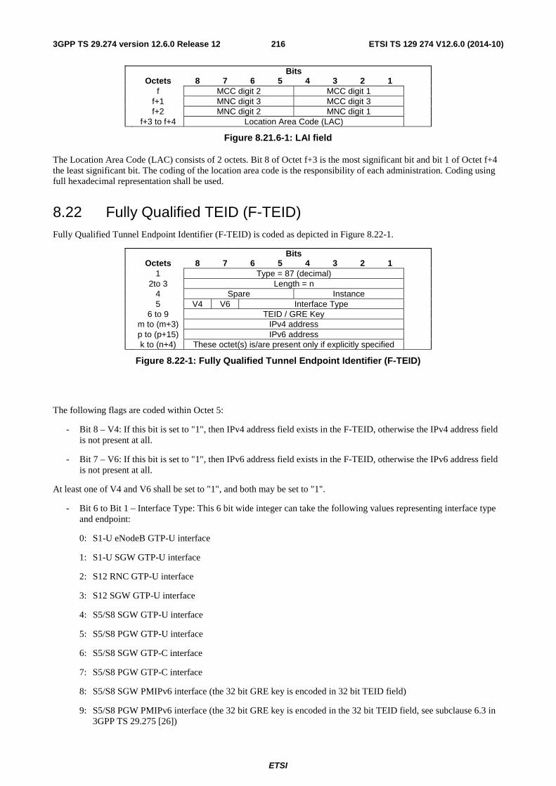
ETSI
ETSI TS 129 274 V12.6.0 (2014-10)2163GPP TS 29.274 version 12.6.0 Release 12
Bits Octets 8 7 6 5 4 3 2 1 f MCC digit 2 MCC digit 1 f+1 MNC digit 3 MCC digit 3 f+2 MNC digit 2 MNC digit 1 f+3 to f+4 Location Area Code (LAC)
Figure 8.21.6-1: LAI field
The Location Area Code (LAC) consists of 2 octets. Bit 8 of Octet f+3 is the most significant bit and bit 1 of Octet f+4 the least significant bit. The coding of the location area code is the responsibility of each administration. Coding using full hexadecimal representation shall be used.
8.22 Fully Qualified TEID (F-TEID) Fully Qualified Tunnel Endpoint Identifier (F-TEID) is coded as depicted in Figure 8.22-1.
Bits Octets 8 7 6 5 4 3 2 1 1 Type = 87 (decimal) 2to 3 Length = n 4 Spare Instance 5 V4 V6 Interface Type 6 to 9 TEID / GRE Key m to (m+3) IPv4 address p to (p+15) IPv6 address k to (n+4) These octet(s) is/are present only if explicitly specified
Figure 8.22-1: Fully Qualified Tunnel Endpoint Identifier (F-TEID)
The following flags are coded within Octet 5:
- Bit 8 – V4: If this bit is set to "1", then IPv4 address field exists in the F-TEID, otherwise the IPv4 address field is not present at all.
- Bit 7 – V6: If this bit is set to "1", then IPv6 address field exists in the F-TEID, otherwise the IPv6 address field is not present at all.
At least one of V4 and V6 shall be set to "1", and both may be set to "1".
- Bit 6 to Bit 1 – Interface Type: This 6 bit wide integer can take the following values representing interface type and endpoint:
0: S1-U eNodeB GTP-U interface
1: S1-U SGW GTP-U interface
2: S12 RNC GTP-U interface
3: S12 SGW GTP-U interface
4: S5/S8 SGW GTP-U interface
5: S5/S8 PGW GTP-U interface
6: S5/S8 SGW GTP-C interface
7: S5/S8 PGW GTP-C interface
8: S5/S8 SGW PMIPv6 interface (the 32 bit GRE key is encoded in 32 bit TEID field)
9: S5/S8 PGW PMIPv6 interface (the 32 bit GRE key is encoded in the 32 bit TEID field, see subclause 6.3 in 3GPP TS 29.275 [26])
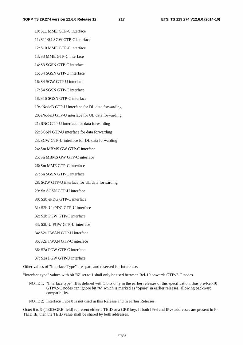
ETSI
ETSI TS 129 274 V12.6.0 (2014-10)2173GPP TS 29.274 version 12.6.0 Release 12
10: S11 MME GTP-C interface
11: S11/S4 SGW GTP-C interface
12: S10 MME GTP-C interface
13: S3 MME GTP-C interface
14: S3 SGSN GTP-C interface
15: S4 SGSN GTP-U interface
16: S4 SGW GTP-U interface
17: S4 SGSN GTP-C interface
18: S16 SGSN GTP-C interface
19: eNodeB GTP-U interface for DL data forwarding
20: eNodeB GTP-U interface for UL data forwarding
21: RNC GTP-U interface for data forwarding
22: SGSN GTP-U interface for data forwarding
23: SGW GTP-U interface for DL data forwarding
24: Sm MBMS GW GTP-C interface
25: Sn MBMS GW GTP-C interface
26: Sm MME GTP-C interface
27: Sn SGSN GTP-C interface
28: SGW GTP-U interface for UL data forwarding
29: Sn SGSN GTP-U interface
30: S2b ePDG GTP-C interface
31: S2b-U ePDG GTP-U interface
32: S2b PGW GTP-C interface
33: S2b-U PGW GTP-U interface
34: S2a TWAN GTP-U interface
35: S2a TWAN GTP-C interface
36: S2a PGW GTP-C interface
37: S2a PGW GTP-U interface
Other values of "Interface Type" are spare and reserved for future use.
"Interface type" values with bit "6" set to 1 shall only be used between Rel-10 onwards GTPv2-C nodes.
NOTE 1: "Interface type" IE is defined with 5 bits only in the earlier releases of this specification, thus pre-Rel-10 GTPv2-C nodes can ignore bit "6" which is marked as "Spare" in earlier releases, allowing backward compatibility.
NOTE 2: Interface Type 8 is not used in this Release and in earlier Releases.
Octet 6 to 9 (TEID/GRE field) represent either a TEID or a GRE key. If both IPv4 and IPv6 addresses are present in F-TEID IE, then the TEID value shall be shared by both addresses.
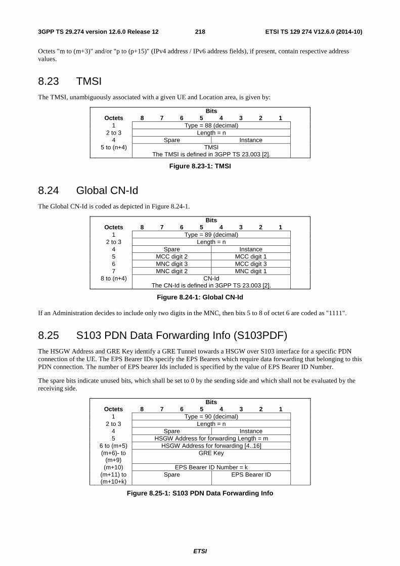
ETSI
ETSI TS 129 274 V12.6.0 (2014-10)2183GPP TS 29.274 version 12.6.0 Release 12
Octets "m to (m+3)" and/or "p to (p+15)" (IPv4 address / IPv6 address fields), if present, contain respective address values.
8.23 TMSI The TMSI, unambiguously associated with a given UE and Location area, is given by:
Bits Octets 8 7 6 5 4 3 2 1 1 Type = 88 (decimal) 2 to 3 Length = n 4 Spare Instance 5 to (n+4) TMSI
The TMSI is defined in 3GPP TS 23.003 [2].
Figure 8.23-1: TMSI
8.24 Global CN-Id The Global CN-Id is coded as depicted in Figure 8.24-1.
Bits Octets 8 7 6 5 4 3 2 1 1 Type = 89 (decimal) 2 to 3 Length = n 4 Spare Instance 5 MCC digit 2 MCC digit 1 6 MNC digit 3 MCC digit 3 7 MNC digit 2 MNC digit 1 8 to (n+4) CN-Id
The CN-Id is defined in 3GPP TS 23.003 [2].
Figure 8.24-1: Global CN-Id
If an Administration decides to include only two digits in the MNC, then bits 5 to 8 of octet 6 are coded as "1111".
8.25 S103 PDN Data Forwarding Info (S103PDF) The HSGW Address and GRE Key identify a GRE Tunnel towards a HSGW over S103 interface for a specific PDN connection of the UE. The EPS Bearer IDs specify the EPS Bearers which require data forwarding that belonging to this PDN connection. The number of EPS bearer Ids included is specified by the value of EPS Bearer ID Number.
The spare bits indicate unused bits, which shall be set to 0 by the sending side and which shall not be evaluated by the receiving side.
Bits Octets 8 7 6 5 4 3 2 1 1 Type = 90 (decimal) 2 to 3 Length = n 4 Spare Instance 5 HSGW Address for forwarding Length = m 6 to (m+5) HSGW Address for forwarding [4..16] (m+6)- to
(m+9) GRE Key
(m+10) EPS Bearer ID Number = k (m+11) to
(m+10+k) Spare EPS Bearer ID
Figure 8.25-1: S103 PDN Data Forwarding Info
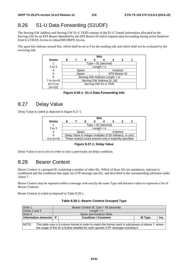
ETSI
ETSI TS 129 274 V12.6.0 (2014-10)2193GPP TS 29.274 version 12.6.0 Release 12
8.26 S1-U Data Forwarding (S1UDF) The Serving GW Address and Serving GW S1-U TEID consists of the S1-U Tunnel information allocated by the Serving GW for an EPS Bearer identified by the EPS Bearer ID which requires data forwarding during active handover from E-UTRAN Access to cdma2000 HRPD Access.
The spare bits indicate unused bits, which shall be set to 0 by the sending side and which shall not be evaluated by the receiving side.
Bits Octets 8 7 6 5 4 3 2 1 1 Type = 91 (decimal) 2 to 3 Length = n 4 Spare Instance 5 Spare EPS Bearer ID 6 Serving GW Address Length = m 7 to (m+6) Serving GW Address [4..16] (m+7) to
(m+10) Serving GW S1-U TEID
Figure 8.26-1: S1-U Data Forwarding Info
8.27 Delay Value Delay Value is coded as depicted in Figure 8.27-1.
Bits Octets 8 7 6 5 4 3 2 1 1 Type = 92 (decimal) 2 to 3 Length = n 4 Spare Instance 5 Delay Value in integer multiples of 50 millisecs, or zero 6 to (n+4) These octet(s) is/are present only if explicitly specified
Figure 8.27-1: Delay Value
Delay Value is set to zero in order to clear a previously set delay condition.
8.28 Bearer Context Bearer Context is a grouped IE containing a number of other IEs. Which of those IEs are mandatory, optional or conditional and the conditions that apply are GTP message specific, and described in the corresponding subclause under clause 7.
Bearer Context may be repeated within a message with exactly the same Type and Instance values to represent a list of Bearer Contexts.
Bearer Context is coded as depicted in Table 8.28-1.
Table 8.28-1: Bearer Context Grouped Type
Octet 1 Bearer Context IE Type = 93 (decimal) Octets 2 and 3 Length = n Octet 4 Spare and Instance fields Information elements P Condition / Comment IE Type Ins.
NOTE: This table uses a 5-column format in order to match the format used in subclauses of clause 7, where
the usage of this IE is further detailed for each specific GTP message including it.
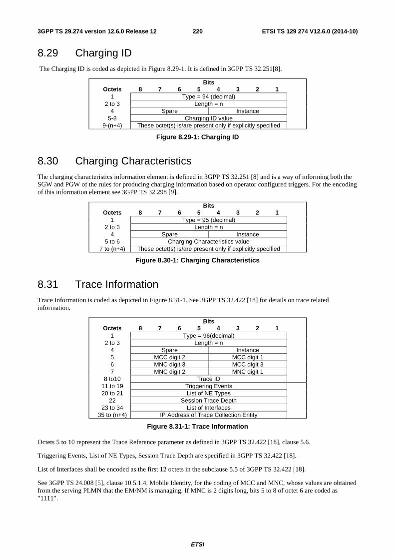
ETSI
ETSI TS 129 274 V12.6.0 (2014-10)2203GPP TS 29.274 version 12.6.0 Release 12
8.29 Charging ID The Charging ID is coded as depicted in Figure 8.29-1. It is defined in 3GPP TS 32.251[8].
Bits Octets 8 7 6 5 4 3 2 1 1 Type = 94 (decimal) 2 to 3 Length = n 4 Spare Instance 5-8 Charging ID value 9-(n+4) These octet(s) is/are present only if explicitly specified
Figure 8.29-1: Charging ID
8.30 Charging Characteristics The charging characteristics information element is defined in 3GPP TS 32.251 [8] and is a way of informing both the SGW and PGW of the rules for producing charging information based on operator configured triggers. For the encoding of this information element see 3GPP TS 32.298 [9].
Bits Octets 8 7 6 5 4 3 2 1 1 Type = 95 (decimal) 2 to 3 Length = n 4 Spare Instance 5 to 6 Charging Characteristics value 7 to (n+4) These octet(s) is/are present only if explicitly specified
Figure 8.30-1: Charging Characteristics
8.31 Trace Information Trace Information is coded as depicted in Figure 8.31-1. See 3GPP TS 32.422 [18] for details on trace related information.
Bits Octets 8 7 6 5 4 3 2 1 1 Type = 96(decimal) 2 to 3 Length = n 4 Spare Instance 5 MCC digit 2 MCC digit 1 6 MNC digit 3 MCC digit 3 7 MNC digit 2 MNC digit 1 8 to10 Trace ID 11 to 19 Triggering Events 20 to 21 List of NE Types 22 Session Trace Depth 23 to 34 List of Interfaces 35 to (n+4) IP Address of Trace Collection Entity
Figure 8.31-1: Trace Information
Octets 5 to 10 represent the Trace Reference parameter as defined in 3GPP TS 32.422 [18], clause 5.6.
Triggering Events, List of NE Types, Session Trace Depth are specified in 3GPP TS 32.422 [18].
List of Interfaces shall be encoded as the first 12 octets in the subclause 5.5 of 3GPP TS 32.422 [18].
See 3GPP TS 24.008 [5], clause 10.5.1.4, Mobile Identity, for the coding of MCC and MNC, whose values are obtained from the serving PLMN that the EM/NM is managing. If MNC is 2 digits long, bits 5 to 8 of octet 6 are coded as "1111".
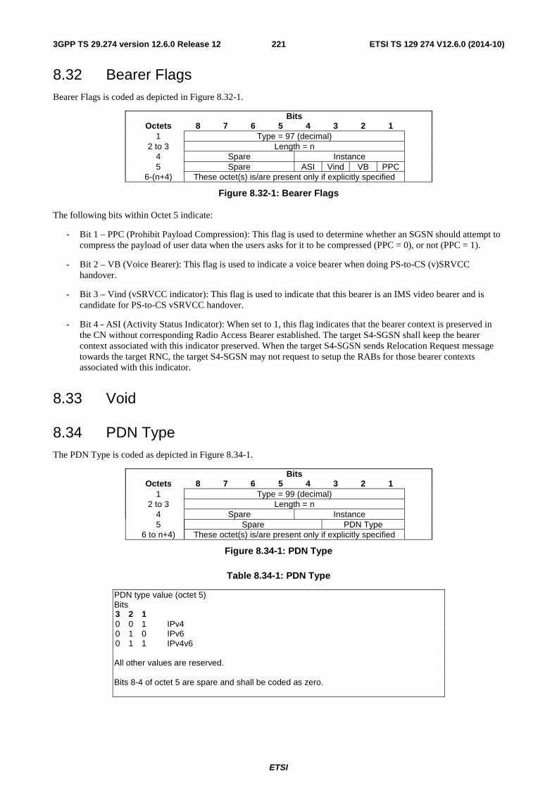
ETSI
ETSI TS 129 274 V12.6.0 (2014-10)2213GPP TS 29.274 version 12.6.0 Release 12
8.32 Bearer Flags Bearer Flags is coded as depicted in Figure 8.32-1.
Bits Octets 8 7 6 5 4 3 2 1 1 Type = 97 (decimal) 2 to 3 Length = n 4 Spare Instance 5 Spare ASI Vind VB PPC 6-(n+4) These octet(s) is/are present only if explicitly specified
Figure 8.32-1: Bearer Flags
The following bits within Octet 5 indicate:
- Bit 1 – PPC (Prohibit Payload Compression): This flag is used to determine whether an SGSN should attempt to compress the payload of user data when the users asks for it to be compressed (PPC = 0), or not (PPC = 1).
- Bit 2 – VB (Voice Bearer): This flag is used to indicate a voice bearer when doing PS-to-CS (v)SRVCC handover.
- Bit 3 – Vind (vSRVCC indicator): This flag is used to indicate that this bearer is an IMS video bearer and is candidate for PS-to-CS vSRVCC handover.
- Bit 4 - ASI (Activity Status Indicator): When set to 1, this flag indicates that the bearer context is preserved in the CN without corresponding Radio Access Bearer established. The target S4-SGSN shall keep the bearer context associated with this indicator preserved. When the target S4-SGSN sends Relocation Request message towards the target RNC, the target S4-SGSN may not request to setup the RABs for those bearer contexts associated with this indicator.
8.33 Void
8.34 PDN Type The PDN Type is coded as depicted in Figure 8.34-1.
Bits Octets 8 7 6 5 4 3 2 1 1 Type = 99 (decimal) 2 to 3 Length = n 4 Spare Instance 5 Spare PDN Type 6 to n+4) These octet(s) is/are present only if explicitly specified
Figure 8.34-1: PDN Type
Table 8.34-1: PDN Type
PDN type value (octet 5) Bits 3 2 1 0 0 1 IPv4 0 1 0 IPv6 0 1 1 IPv4v6 All other values are reserved. Bits 8-4 of octet 5 are spare and shall be coded as zero.
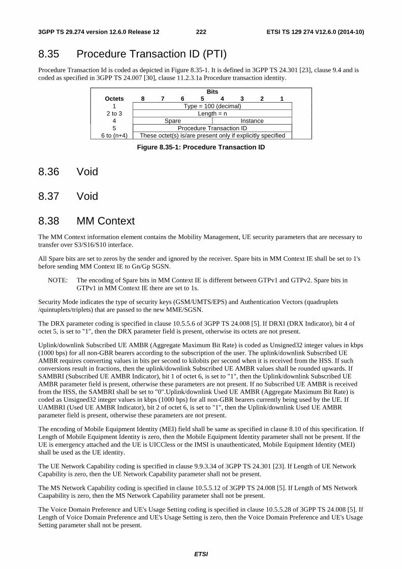
ETSI
ETSI TS 129 274 V12.6.0 (2014-10)2223GPP TS 29.274 version 12.6.0 Release 12
8.35 Procedure Transaction ID (PTI) Procedure Transaction Id is coded as depicted in Figure 8.35-1. It is defined in 3GPP TS 24.301 [23], clause 9.4 and is coded as specified in 3GPP TS 24.007 [30], clause 11.2.3.1a Procedure transaction identity.
Bits Octets 8 7 6 5 4 3 2 1 1 Type = 100 (decimal) 2 to 3 Length = n 4 Spare Instance 5 Procedure Transaction ID 6 to (n+4) These octet(s) is/are present only if explicitly specified
Figure 8.35-1: Procedure Transaction ID
8.36 Void
8.37 Void
8.38 MM Context The MM Context information element contains the Mobility Management, UE security parameters that are necessary to transfer over S3/S16/S10 interface.
All Spare bits are set to zeros by the sender and ignored by the receiver. Spare bits in MM Context IE shall be set to 1's before sending MM Context IE to Gn/Gp SGSN.
NOTE: The encoding of Spare bits in MM Context IE is different between GTPv1 and GTPv2. Spare bits in GTPv1 in MM Context IE there are set to 1s.
Security Mode indicates the type of security keys (GSM/UMTS/EPS) and Authentication Vectors (quadruplets /quintuplets/triplets) that are passed to the new MME/SGSN.
The DRX parameter coding is specified in clause 10.5.5.6 of 3GPP TS 24.008 [5]. If DRXI (DRX Indicator), bit 4 of octet 5, is set to "1", then the DRX parameter field is present, otherwise its octets are not present.
Uplink/downlink Subscribed UE AMBR (Aggregate Maximum Bit Rate) is coded as Unsigned32 integer values in kbps (1000 bps) for all non-GBR bearers according to the subscription of the user. The uplink/downlink Subscribed UE AMBR requires converting values in bits per second to kilobits per second when it is received from the HSS. If such conversions result in fractions, then the uplink/downlink Subscribed UE AMBR values shall be rounded upwards. If SAMBRI (Subscribed UE AMBR Indicator), bit 1 of octet 6, is set to "1", then the Uplink/downlink Subscribed UE AMBR parameter field is present, otherwise these parameters are not present. If no Subscribed UE AMBR is received from the HSS, the SAMBRI shall be set to "0".Uplink/downlink Used UE AMBR (Aggregate Maximum Bit Rate) is coded as Unsigned32 integer values in kbps (1000 bps) for all non-GBR bearers currently being used by the UE. If UAMBRI (Used UE AMBR Indicator), bit 2 of octet 6, is set to "1", then the Uplink/downlink Used UE AMBR parameter field is present, otherwise these parameters are not present.
The encoding of Mobile Equipment Identity (MEI) field shall be same as specified in clause 8.10 of this specification. If Length of Mobile Equipment Identity is zero, then the Mobile Equipment Identity parameter shall not be present. If the UE is emergency attached and the UE is UICCless or the IMSI is unauthenticated, Mobile Equipment Identity (MEI) shall be used as the UE identity.
The UE Network Capability coding is specified in clause 9.9.3.34 of 3GPP TS 24.301 [23]. If Length of UE Network Capability is zero, then the UE Network Capability parameter shall not be present.
The MS Network Capability coding is specified in clause 10.5.5.12 of 3GPP TS 24.008 [5]. If Length of MS Network Caapability is zero, then the MS Network Capability parameter shall not be present.
The Voice Domain Preference and UE's Usage Setting coding is specified in clause 10.5.5.28 of 3GPP TS 24.008 [5]. If Length of Voice Domain Preference and UE's Usage Setting is zero, then the Voice Domain Preference and UE's Usage Setting parameter shall not be present.
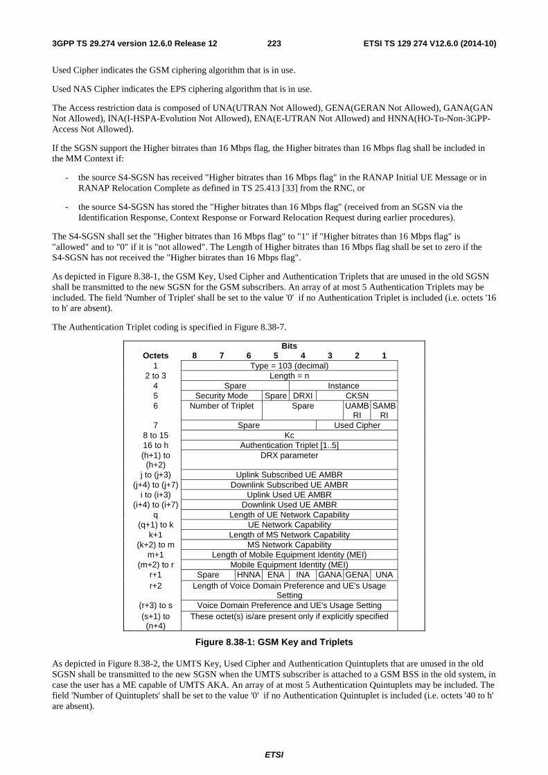
ETSI
ETSI TS 129 274 V12.6.0 (2014-10)2233GPP TS 29.274 version 12.6.0 Release 12
Used Cipher indicates the GSM ciphering algorithm that is in use.
Used NAS Cipher indicates the EPS ciphering algorithm that is in use.
The Access restriction data is composed of UNA(UTRAN Not Allowed), GENA(GERAN Not Allowed), GANA(GAN Not Allowed), INA(I-HSPA-Evolution Not Allowed), ENA(E-UTRAN Not Allowed) and HNNA(HO-To-Non-3GPP-Access Not Allowed).
If the SGSN support the Higher bitrates than 16 Mbps flag, the Higher bitrates than 16 Mbps flag shall be included in the MM Context if:
- the source S4-SGSN has received "Higher bitrates than 16 Mbps flag" in the RANAP Initial UE Message or in RANAP Relocation Complete as defined in TS 25.413 [33] from the RNC, or
- the source S4-SGSN has stored the "Higher bitrates than 16 Mbps flag" (received from an SGSN via the Identification Response, Context Response or Forward Relocation Request during earlier procedures).
The S4-SGSN shall set the "Higher bitrates than 16 Mbps flag" to "1" if "Higher bitrates than 16 Mbps flag" is "allowed" and to "0" if it is "not allowed". The Length of Higher bitrates than 16 Mbps flag shall be set to zero if the S4-SGSN has not received the "Higher bitrates than 16 Mbps flag".
As depicted in Figure 8.38-1, the GSM Key, Used Cipher and Authentication Triplets that are unused in the old SGSN shall be transmitted to the new SGSN for the GSM subscribers. An array of at most 5 Authentication Triplets may be included. The field 'Number of Triplet' shall be set to the value '0' if no Authentication Triplet is included (i.e. octets '16 to h' are absent).
The Authentication Triplet coding is specified in Figure 8.38-7.
Bits Octets 8 7 6 5 4 3 2 1 1 Type = 103 (decimal) 2 to 3 Length = n 4 Spare Instance 5 Security Mode Spare DRXI CKSN 6 Number of Triplet Spare UAMB
RI SAMB
RI
7 Spare Used Cipher 8 to 15 Kc 16 to h Authentication Triplet [1..5] (h+1) to
(h+2) DRX parameter
j to (j+3) Uplink Subscribed UE AMBR (j+4) to (j+7) Downlink Subscribed UE AMBR i to (i+3) Uplink Used UE AMBR (i+4) to (i+7) Downlink Used UE AMBR q Length of UE Network Capability (q+1) to k UE Network Capability k+1 Length of MS Network Capability (k+2) to m MS Network Capability m+1 Length of Mobile Equipment Identity (MEI) (m+2) to r Mobile Equipment Identity (MEI)
r+1 Spare HNNA ENA INA GANA GENA UNA r+2 Length of Voice Domain Preference and UE's Usage
Setting
(r+3) to s Voice Domain Preference and UE's Usage Setting (s+1) to (n+4)
These octet(s) is/are present only if explicitly specified
Figure 8.38-1: GSM Key and Triplets
As depicted in Figure 8.38-2, the UMTS Key, Used Cipher and Authentication Quintuplets that are unused in the old SGSN shall be transmitted to the new SGSN when the UMTS subscriber is attached to a GSM BSS in the old system, in case the user has a ME capable of UMTS AKA. An array of at most 5 Authentication Quintuplets may be included. The field 'Number of Quintuplets' shall be set to the value '0' if no Authentication Quintuplet is included (i.e. octets '40 to h' are absent).
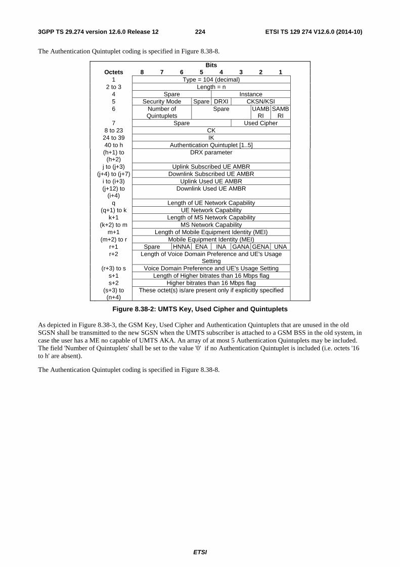
ETSI
ETSI TS 129 274 V12.6.0 (2014-10)2243GPP TS 29.274 version 12.6.0 Release 12
The Authentication Quintuplet coding is specified in Figure 8.38-8.
Bits Octets 8 7 6 5 4 3 2 1 1 Type = 104 (decimal) 2 to 3 Length = n 4 Spare Instance 5 Security Mode Spare DRXI CKSN/KSI 6 Number of
Quintuplets Spare UAMB
RI SAMB
RI
7 Spare Used Cipher 8 to 23 CK 24 to 39 IK 40 to h Authentication Quintuplet [1..5] (h+1) to
(h+2) DRX parameter
j to (j+3) Uplink Subscribed UE AMBR (j+4) to (j+7) Downlink Subscribed UE AMBR i to (i+3) Uplink Used UE AMBR (j+12) to
(i+4) Downlink Used UE AMBR
q Length of UE Network Capability (q+1) to k UE Network Capability k+1 Length of MS Network Capability (k+2) to m MS Network Capability m+1 Length of Mobile Equipment Identity (MEI) (m+2) to r Mobile Equipment Identity (MEI) r+1 Spare HNNA ENA INA GANA GENA UNA r+2 Length of Voice Domain Preference and UE's Usage
Setting
(r+3) to s Voice Domain Preference and UE's Usage Setting s+1 Length of Higher bitrates than 16 Mbps flag s+2 Higher bitrates than 16 Mbps flag (s+3) to
(n+4) These octet(s) is/are present only if explicitly specified
Figure 8.38-2: UMTS Key, Used Cipher and Quintuplets
As depicted in Figure 8.38-3, the GSM Key, Used Cipher and Authentication Quintuplets that are unused in the old SGSN shall be transmitted to the new SGSN when the UMTS subscriber is attached to a GSM BSS in the old system, in case the user has a ME no capable of UMTS AKA. An array of at most 5 Authentication Quintuplets may be included. The field 'Number of Quintuplets' shall be set to the value '0' if no Authentication Quintuplet is included (i.e. octets '16 to h' are absent).
The Authentication Quintuplet coding is specified in Figure 8.38-8.
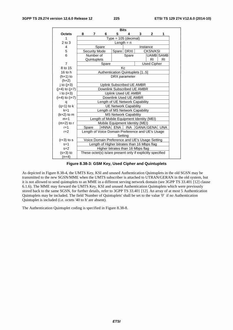
ETSI
ETSI TS 129 274 V12.6.0 (2014-10)2253GPP TS 29.274 version 12.6.0 Release 12
Bits Octets 8 7 6 5 4 3 2 1 1 Type = 105 (decimal) 2 to 3 Length = n 4 Spare Instance 5 Security Mode Spare DRXI CKSN/KSI 6 Number of
Quintuplets Spare UAMB
RI SAMB
RI
7 Spare Used Cipher 8 to 15 Kc 16 to h Authentication Quintuplets [1..5] (h+1) to
(h+2) DRX parameter
j to (j+3) Uplink Subscribed UE AMBR (j+4) to (j+7) Downlink Subscribed UE AMBR i to (i+3) Uplink Used UE AMBR (i+4) to (i+7) Downlink Used UE AMBR q Length of UE Network Capability (q+1) to k UE Network Capability k+1 Length of MS Network Capability (k+2) to m MS Network Capability m+1 Length of Mobile Equipment Identity (MEI) (m+2) to r Mobile Equipment Identity (MEI) r+1 Spare HNNA ENA INA GANA GENA UNA r+2 Length of Voice Domain Preference and UE's Usage
Setting
(r+3) to s Voice Domain Preference and UE's Usage Setting s+1 Length of Higher bitrates than 16 Mbps flag s+2 Higher bitrates than 16 Mbps flag (s+3) to
(n+4) These octet(s) is/are present only if explicitly specified
Figure 8.38-3: GSM Key, Used Cipher and Quintuplets
As depicted in Figure 8.38-4, the UMTS Key, KSI and unused Authentication Quintuplets in the old SGSN may be transmitted to the new SGSN/MME when the UMTS subscriber is attached to UTRAN/GERAN in the old system, but it is not allowed to send quintuplets to an MME in a different serving network domain (see 3GPP TS 33.401 [12] clause 6.1.6). The MME may forward the UMTS Key, KSI and unused Authentication Quintuplets which were previously stored back to the same SGSN, for further details, refer to 3GPP TS 33.401 [12]. An array of at most 5 Authentication Quintuplets may be included. The field 'Number of Quintuplets' shall be set to the value '0' if no Authentication Quintuplet is included (i.e. octets '40 to h' are absent).
The Authentication Quintuplet coding is specified in Figure 8.38-8.
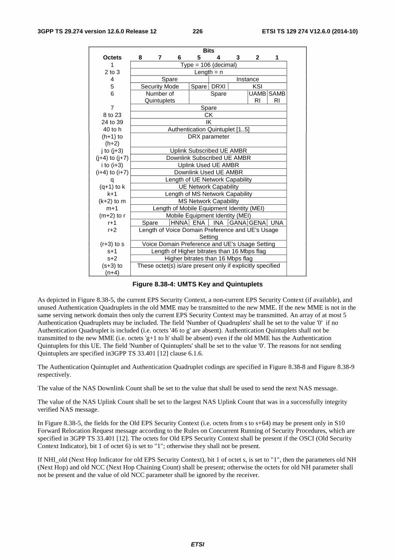
ETSI
ETSI TS 129 274 V12.6.0 (2014-10)2263GPP TS 29.274 version 12.6.0 Release 12
Bits Octets 8 7 6 5 4 3 2 1 1 Type = 106 (decimal) 2 to 3 Length = n 4 Spare Instance 5 Security Mode Spare DRXI KSI 6 Number of
Quintuplets Spare UAMB
RI SAMB
RI
7 Spare 8 to 23 CK 24 to 39 IK 40 to h Authentication Quintuplet [1..5] (h+1) to
(h+2) DRX parameter
j to (j+3) Uplink Subscribed UE AMBR (j+4) to (j+7) Downlink Subscribed UE AMBR i to (i+3) Uplink Used UE AMBR (i+4) to (i+7) Downlink Used UE AMBR q Length of UE Network Capability (q+1) to k UE Network Capability k+1 Length of MS Network Capability (k+2) to m MS Network Capability m+1 Length of Mobile Equipment Identity (MEI) (m+2) to r Mobile Equipment Identity (MEI) r+1 Spare HNNA ENA INA GANA GENA UNA r+2 Length of Voice Domain Preference and UE's Usage
Setting
(r+3) to s Voice Domain Preference and UE's Usage Setting s+1 Length of Higher bitrates than 16 Mbps flag s+2 Higher bitrates than 16 Mbps flag (s+3) to
(n+4) These octet(s) is/are present only if explicitly specified
Figure 8.38-4: UMTS Key and Quintuplets
As depicted in Figure 8.38-5, the current EPS Security Context, a non-current EPS Security Context (if available), and unused Authentication Quadruplets in the old MME may be transmitted to the new MME. If the new MME is not in the same serving network domain then only the current EPS Security Context may be transmitted. An array of at most 5 Authentication Quadruplets may be included. The field 'Number of Quadruplets' shall be set to the value '0' if no Authentication Quadruplet is included (i.e. octets '46 to g' are absent). Authentication Quintuplets shall not be transmitted to the new MME (i.e. octets 'g+1 to h' shall be absent) even if the old MME has the Authentication Quintuplets for this UE. The field 'Number of Quintuplets' shall be set to the value '0'. The reasons for not sending Quintuplets are specified in3GPP TS 33.401 [12] clause 6.1.6.
The Authentication Quintuplet and Authentication Quadruplet codings are specified in Figure 8.38-8 and Figure 8.38-9 respectively.
The value of the NAS Downlink Count shall be set to the value that shall be used to send the next NAS message.
The value of the NAS Uplink Count shall be set to the largest NAS Uplink Count that was in a successfully integrity verified NAS message.
In Figure 8.38-5, the fields for the Old EPS Security Context (i.e. octets from s to s+64) may be present only in S10 Forward Relocation Request message according to the Rules on Concurrent Running of Security Procedures, which are specified in 3GPP TS 33.401 [12]. The octets for Old EPS Security Context shall be present if the OSCI (Old Security Context Indicator), bit 1 of octet 6) is set to "1"; otherwise they shall not be present.
If NHI_old (Next Hop Indicator for old EPS Security Context), bit 1 of octet s, is set to "1", then the parameters old NH (Next Hop) and old NCC (Next Hop Chaining Count) shall be present; otherwise the octets for old NH parameter shall not be present and the value of old NCC parameter shall be ignored by the receiver.
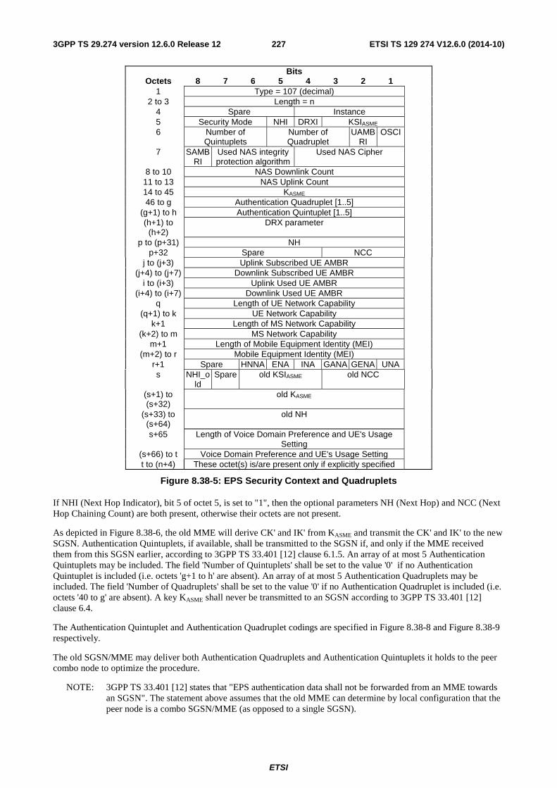
ETSI
ETSI TS 129 274 V12.6.0 (2014-10)2273GPP TS 29.274 version 12.6.0 Release 12
Bits Octets 8 7 6 5 4 3 2 1 1 Type = 107 (decimal) 2 to 3 Length = n 4 Spare Instance 5 Security Mode NHI DRXI KSIASME 6 Number of
Quintuplets Number of Quadruplet
UAMBRI
OSCI
7 SAMBRI
Used NAS integrity protection algorithm
Used NAS Cipher
8 to 10 NAS Downlink Count 11 to 13 NAS Uplink Count 14 to 45 KASME 46 to g Authentication Quadruplet [1..5] (g+1) to h Authentication Quintuplet [1..5] (h+1) to
(h+2) DRX parameter
p to (p+31) NH p+32 Spare NCC j to (j+3) Uplink Subscribed UE AMBR (j+4) to (j+7) Downlink Subscribed UE AMBR i to (i+3) Uplink Used UE AMBR (i+4) to (i+7) Downlink Used UE AMBR q Length of UE Network Capability (q+1) to k UE Network Capability k+1 Length of MS Network Capability (k+2) to m MS Network Capability m+1 Length of Mobile Equipment Identity (MEI) (m+2) to r Mobile Equipment Identity (MEI) r+1 Spare HNNA ENA INA GANA GENA UNA s NHI_o
ld Spare old KSIASME old NCC
(s+1) to (s+32)
old KASME
(s+33) to (s+64)
old NH
s+65 Length of Voice Domain Preference and UE's Usage Setting
(s+66) to t Voice Domain Preference and UE's Usage Setting t to (n+4) These octet(s) is/are present only if explicitly specified
Figure 8.38-5: EPS Security Context and Quadruplets
If NHI (Next Hop Indicator), bit 5 of octet 5, is set to "1", then the optional parameters NH (Next Hop) and NCC (Next Hop Chaining Count) are both present, otherwise their octets are not present.
As depicted in Figure 8.38-6, the old MME will derive CK' and IK' from KASME and transmit the CK' and IK' to the new SGSN. Authentication Quintuplets, if available, shall be transmitted to the SGSN if, and only if the MME received them from this SGSN earlier, according to 3GPP TS 33.401 [12] clause 6.1.5. An array of at most 5 Authentication Quintuplets may be included. The field 'Number of Quintuplets' shall be set to the value '0' if no Authentication Quintuplet is included (i.e. octets 'g+1 to h' are absent). An array of at most 5 Authentication Quadruplets may be included. The field 'Number of Quadruplets' shall be set to the value '0' if no Authentication Quadruplet is included (i.e. octets '40 to g' are absent). A key KASME shall never be transmitted to an SGSN according to 3GPP TS 33.401 [12] clause 6.4.
The Authentication Quintuplet and Authentication Quadruplet codings are specified in Figure 8.38-8 and Figure 8.38-9 respectively.
The old SGSN/MME may deliver both Authentication Quadruplets and Authentication Quintuplets it holds to the peer combo node to optimize the procedure.
NOTE: 3GPP TS 33.401 [12] states that "EPS authentication data shall not be forwarded from an MME towards an SGSN". The statement above assumes that the old MME can determine by local configuration that the peer node is a combo SGSN/MME (as opposed to a single SGSN).
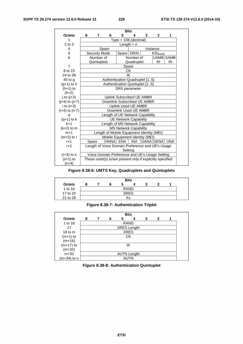
ETSI
ETSI TS 129 274 V12.6.0 (2014-10)2283GPP TS 29.274 version 12.6.0 Release 12
Bits Octets 8 7 6 5 4 3 2 1 1 Type = 108 (decimal) 2 to 3 Length = n 4 Spare Instance 5 Security Mode Spare DRXI KSIASME 6 Number of
Quintuplets Number of Quadruplet
UAMBRI
SAMBRI
7 Spare 8 to 23 CK 24 to 39 IK 40 to g Authentication Quadruplet [1..5] (g+1) to h Authentication Quintuplet [1..5] (h+1) to
(h+2) DRX parameter
j to (j+3) Uplink Subscribed UE AMBR (j+4) to (j+7) Downlink Subscribed UE AMBR i to (i+3) Uplink Used UE AMBR (i+4) to (i+7) Downlink Used UE AMBR q Length of UE Network Capability (q+1) to k UE Network Capability k+1 Length of MS Network Capability (k+2) to m MS Network Capability m+1 Length of Mobile Equipment Identity (MEI) (m+2) to r Mobile Equipment Identity (MEI) r+1 Spare HNNA ENA INA GANA GENA UNA r+2 Length of Voice Domain Preference and UE's Usage
Setting
(r+3) to s Voice Domain Preference and UE's Usage Setting (s+1) to
(n+4) These octet(s) is/are present only if explicitly specified
Figure 8.38-6: UMTS Key, Quadruplets and Quintuplets
Bits Octets 8 7 6 5 4 3 2 1 1 to 16 RAND 17 to 20 SRES 21 to 28 Kc
Figure 8.38-7: Authentication Triplet
Bits Octets 8 7 6 5 4 3 2 1 1 to 16 RAND 17 XRES Length 18 to m XRES (m+1) to
(m+16) CK
(m+17) to (m+32)
IK
m+33 AUTN Length (m+34) to n AUTN
Figure 8.38-8: Authentication Quintuplet
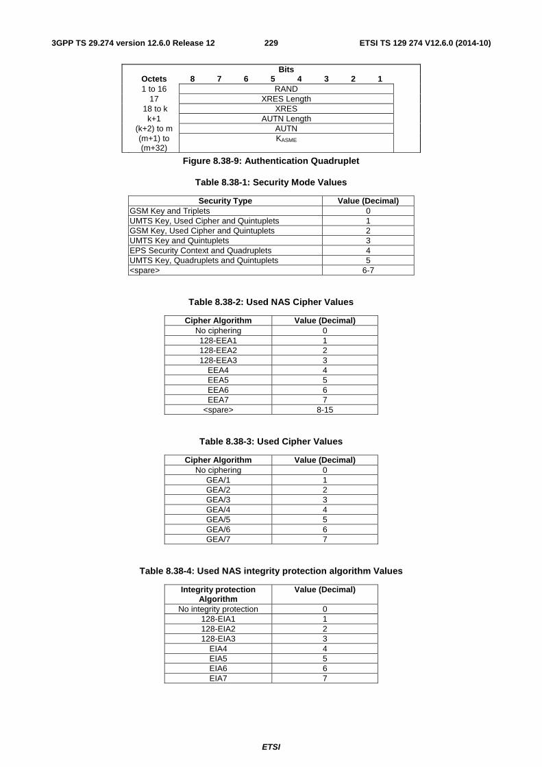
ETSI
ETSI TS 129 274 V12.6.0 (2014-10)2293GPP TS 29.274 version 12.6.0 Release 12
Bits Octets 8 7 6 5 4 3 2 1 1 to 16 RAND 17 XRES Length 18 to k XRES k+1 AUTN Length (k+2) to m AUTN (m+1) to
(m+32) KASME
Figure 8.38-9: Authentication Quadruplet
Table 8.38-1: Security Mode Values
Security Type Value (Decimal) GSM Key and Triplets 0 UMTS Key, Used Cipher and Quintuplets 1 GSM Key, Used Cipher and Quintuplets 2 UMTS Key and Quintuplets 3 EPS Security Context and Quadruplets 4 UMTS Key, Quadruplets and Quintuplets 5 <spare> 6-7
Table 8.38-2: Used NAS Cipher Values
Cipher Algorithm Value (Decimal) No ciphering 0 128-EEA1 1 128-EEA2 2 128-EEA3 3
EEA4 4 EEA5 5 EEA6 6 EEA7 7
<spare> 8-15
Table 8.38-3: Used Cipher Values
Cipher Algorithm Value (Decimal) No ciphering 0
GEA/1 1 GEA/2 2 GEA/3 3 GEA/4 4 GEA/5 5 GEA/6 6 GEA/7 7
Table 8.38-4: Used NAS integrity protection algorithm Values
Integrity protection Algorithm
Value (Decimal)
No integrity protection 0 128-EIA1 1 128-EIA2 2 128-EIA3 3
EIA4 4 EIA5 5 EIA6 6 EIA7 7
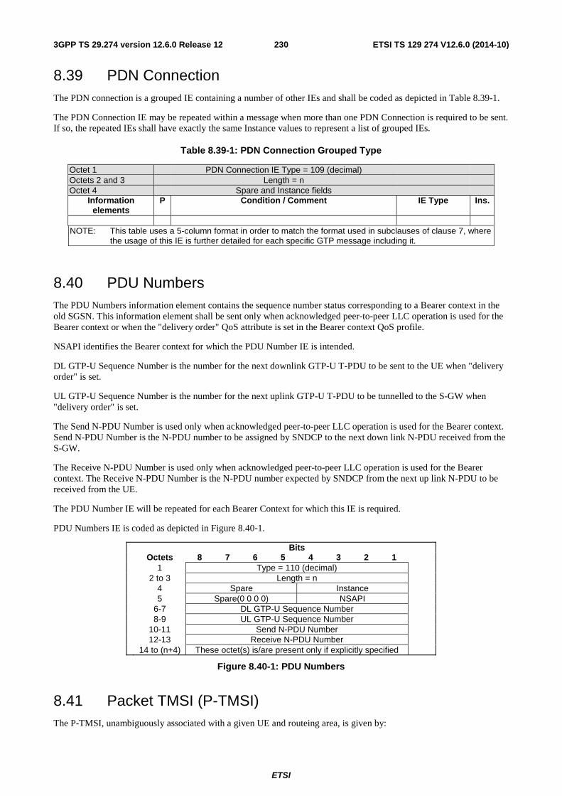
ETSI
ETSI TS 129 274 V12.6.0 (2014-10)2303GPP TS 29.274 version 12.6.0 Release 12
8.39 PDN Connection The PDN connection is a grouped IE containing a number of other IEs and shall be coded as depicted in Table 8.39-1.
The PDN Connection IE may be repeated within a message when more than one PDN Connection is required to be sent. If so, the repeated IEs shall have exactly the same Instance values to represent a list of grouped IEs.
Table 8.39-1: PDN Connection Grouped Type
Octet 1 PDN Connection IE Type = 109 (decimal) Octets 2 and 3 Length = n Octet 4 Spare and Instance fields
Information elements
P Condition / Comment IE Type Ins.
NOTE: This table uses a 5-column format in order to match the format used in subclauses of clause 7, where
the usage of this IE is further detailed for each specific GTP message including it.
8.40 PDU Numbers The PDU Numbers information element contains the sequence number status corresponding to a Bearer context in the old SGSN. This information element shall be sent only when acknowledged peer-to-peer LLC operation is used for the Bearer context or when the "delivery order" QoS attribute is set in the Bearer context QoS profile.
NSAPI identifies the Bearer context for which the PDU Number IE is intended.
DL GTP-U Sequence Number is the number for the next downlink GTP-U T-PDU to be sent to the UE when "delivery order" is set.
UL GTP-U Sequence Number is the number for the next uplink GTP-U T-PDU to be tunnelled to the S-GW when "delivery order" is set.
The Send N-PDU Number is used only when acknowledged peer-to-peer LLC operation is used for the Bearer context. Send N-PDU Number is the N-PDU number to be assigned by SNDCP to the next down link N-PDU received from the S-GW.
The Receive N-PDU Number is used only when acknowledged peer-to-peer LLC operation is used for the Bearer context. The Receive N-PDU Number is the N-PDU number expected by SNDCP from the next up link N-PDU to be received from the UE.
The PDU Number IE will be repeated for each Bearer Context for which this IE is required.
PDU Numbers IE is coded as depicted in Figure 8.40-1.
Bits Octets 8 7 6 5 4 3 2 1
1 Type = 110 (decimal) 2 to 3 Length = n
4 Spare Instance 5 Spare(0 0 0 0) NSAPI
6-7 DL GTP-U Sequence Number 8-9 UL GTP-U Sequence Number
10-11 Send N-PDU Number 12-13 Receive N-PDU Number
14 to (n+4) These octet(s) is/are present only if explicitly specified
Figure 8.40-1: PDU Numbers
8.41 Packet TMSI (P-TMSI) The P-TMSI, unambiguously associated with a given UE and routeing area, is given by:
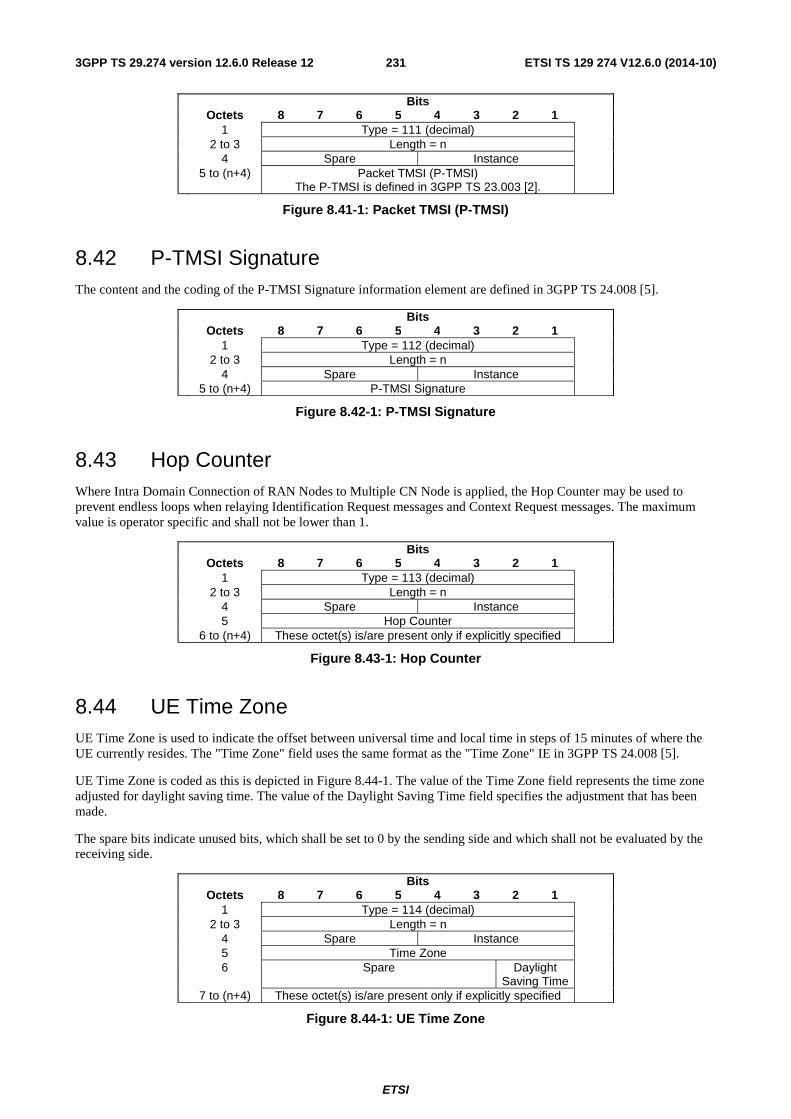
ETSI
ETSI TS 129 274 V12.6.0 (2014-10)2313GPP TS 29.274 version 12.6.0 Release 12
Bits Octets 8 7 6 5 4 3 2 1 1 Type = 111 (decimal) 2 to 3 Length = n 4 Spare Instance 5 to (n+4) Packet TMSI (P-TMSI)
The P-TMSI is defined in 3GPP TS 23.003 [2].
Figure 8.41-1: Packet TMSI (P-TMSI)
8.42 P-TMSI Signature The content and the coding of the P-TMSI Signature information element are defined in 3GPP TS 24.008 [5].
Bits Octets 8 7 6 5 4 3 2 1 1 Type = 112 (decimal) 2 to 3 Length = n 4 Spare Instance 5 to (n+4) P-TMSI Signature
Figure 8.42-1: P-TMSI Signature
8.43 Hop Counter Where Intra Domain Connection of RAN Nodes to Multiple CN Node is applied, the Hop Counter may be used to prevent endless loops when relaying Identification Request messages and Context Request messages. The maximum value is operator specific and shall not be lower than 1.
Bits Octets 8 7 6 5 4 3 2 1 1 Type = 113 (decimal) 2 to 3 Length = n 4 Spare Instance 5 Hop Counter 6 to (n+4) These octet(s) is/are present only if explicitly specified
Figure 8.43-1: Hop Counter
8.44 UE Time Zone UE Time Zone is used to indicate the offset between universal time and local time in steps of 15 minutes of where the UE currently resides. The "Time Zone" field uses the same format as the "Time Zone" IE in 3GPP TS 24.008 [5].
UE Time Zone is coded as this is depicted in Figure 8.44-1. The value of the Time Zone field represents the time zone adjusted for daylight saving time. The value of the Daylight Saving Time field specifies the adjustment that has been made.
The spare bits indicate unused bits, which shall be set to 0 by the sending side and which shall not be evaluated by the receiving side.
Bits Octets 8 7 6 5 4 3 2 1 1 Type = 114 (decimal) 2 to 3 Length = n 4 Spare Instance 5 Time Zone 6 Spare Daylight
Saving Time
7 to (n+4) These octet(s) is/are present only if explicitly specified
Figure 8.44-1: UE Time Zone
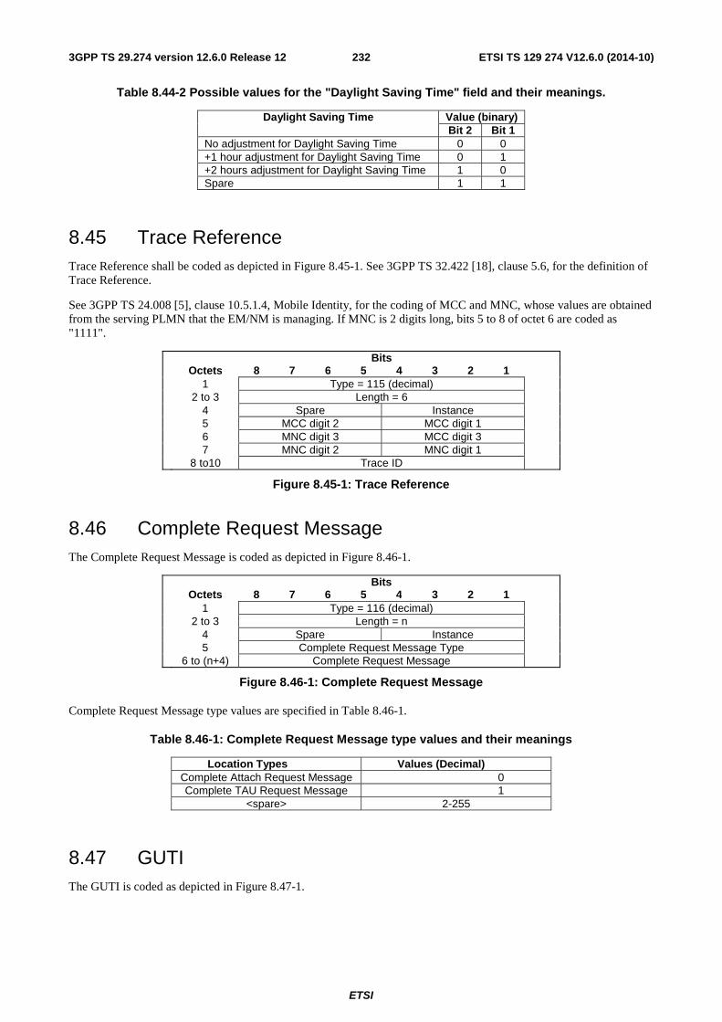
ETSI
ETSI TS 129 274 V12.6.0 (2014-10)2323GPP TS 29.274 version 12.6.0 Release 12
Table 8.44-2 Possible values for the "Daylight Saving Time" field and their meanings.
Daylight Saving Time Value (binary) Bit 2 Bit 1
No adjustment for Daylight Saving Time 0 0 +1 hour adjustment for Daylight Saving Time 0 1 +2 hours adjustment for Daylight Saving Time 1 0 Spare 1 1
8.45 Trace Reference Trace Reference shall be coded as depicted in Figure 8.45-1. See 3GPP TS 32.422 [18], clause 5.6, for the definition of Trace Reference.
See 3GPP TS 24.008 [5], clause 10.5.1.4, Mobile Identity, for the coding of MCC and MNC, whose values are obtained from the serving PLMN that the EM/NM is managing. If MNC is 2 digits long, bits 5 to 8 of octet 6 are coded as "1111".
Bits Octets 8 7 6 5 4 3 2 1 1 Type = 115 (decimal) 2 to 3 Length = 6 4 Spare Instance 5 MCC digit 2 MCC digit 1 6 MNC digit 3 MCC digit 3 7 MNC digit 2 MNC digit 1 8 to10 Trace ID
Figure 8.45-1: Trace Reference
8.46 Complete Request Message The Complete Request Message is coded as depicted in Figure 8.46-1.
Bits Octets 8 7 6 5 4 3 2 1 1 Type = 116 (decimal) 2 to 3 Length = n 4 Spare Instance 5 Complete Request Message Type 6 to (n+4) Complete Request Message
Figure 8.46-1: Complete Request Message
Complete Request Message type values are specified in Table 8.46-1.
Table 8.46-1: Complete Request Message type values and their meanings
Location Types Values (Decimal) Complete Attach Request Message 0 Complete TAU Request Message 1
<spare> 2-255
8.47 GUTI The GUTI is coded as depicted in Figure 8.47-1.
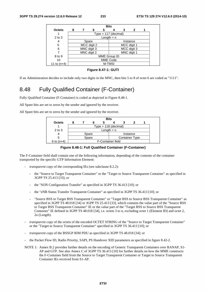
ETSI
ETSI TS 129 274 V12.6.0 (2014-10)2333GPP TS 29.274 version 12.6.0 Release 12
Bits Octets 8 7 6 5 4 3 2 1 1 Type = 117 (decimal) 2 to 3 Length = n 4 Spare Instance 5 MCC digit 2 MCC digit 1 6 MNC digit 3 MCC digit 3 7 MNC digit 2 MNC digit 1 8 to 9 MME Group ID 10 MME Code 11 to (n+4) M-TMSI
Figure 8.47-1: GUTI
If an Administration decides to include only two digits in the MNC, then bits 5 to 8 of octet 6 are coded as "1111".
8.48 Fully Qualified Container (F-Container) Fully Qualified Container (F-Container) is coded as depicted in Figure 8.48-1.
All Spare bits are set to zeros by the sender and ignored by the receiver.
All Spare bits are set to zeros by the sender and ignored by the receiver.
Bits Octets 8 7 6 5 4 3 2 1 1 Type = 118 (decimal) 2 to 3 Length = n 4 Spare Instance 5 Spare Container Type 6 to (n+4) F-Container field
Figure 8.48-1: Full Qualified Container (F-Container)
The F-Container field shall contain one of the following information, depending of the contents of the container transported by the specific GTP Information Element:
- transparent copy of the corresponding IEs (see subclause 8.2.2):
- the "Source to Target Transparent Container" or the "Target to Source Transparent Container" as specified in 3GPP TS 25.413 [33]; or
- the "SON Configuration Transfer" as specified in 3GPP TS 36.413 [10]; or
- the "eNB Status Transfer Transparent Container" as specified in 3GPP TS 36.413 [10]; or
- "Source BSS to Target BSS Transparent Container" or "Target BSS to Source BSS Transparent Container" as specified in 3GPP TS 48.018 [34] or 3GPP TS 25.413 [33], which contains the value part of the "Source BSS to Target BSS Transparent Container" IE or the value part of the "Target BSS to Source BSS Transparent Container" IE defined in 3GPP TS 48.018 [34], i.e. octets 3 to n, excluding octet 1 (Element ID) and octet 2, 2a (Length).
- transparent copy of the octets of the encoded OCTET STRING of the "Source to Target Transparent Container" or the "Target to Source Transparent Container" specified in 3GPP TS 36.413 [10]; or
- transparent copy of the BSSGP RIM PDU as specified in 3GPP TS 48.018 [34]; or
- the Packet Flow ID, Radio Priority, SAPI, PS Handover XID parameters as specified in figure 8.42-2.
NOTE 1: Annex B.2 provides further details on the encoding of Generic Transparent Containers over RANAP, S1-AP and GTP. See also Annex C of 3GPP TS 36.413 [10] for further details on how the MME constructs the F-Container field from the Source to Target Transparent Container or Target to Source Transparent Container IEs received from S1-AP.
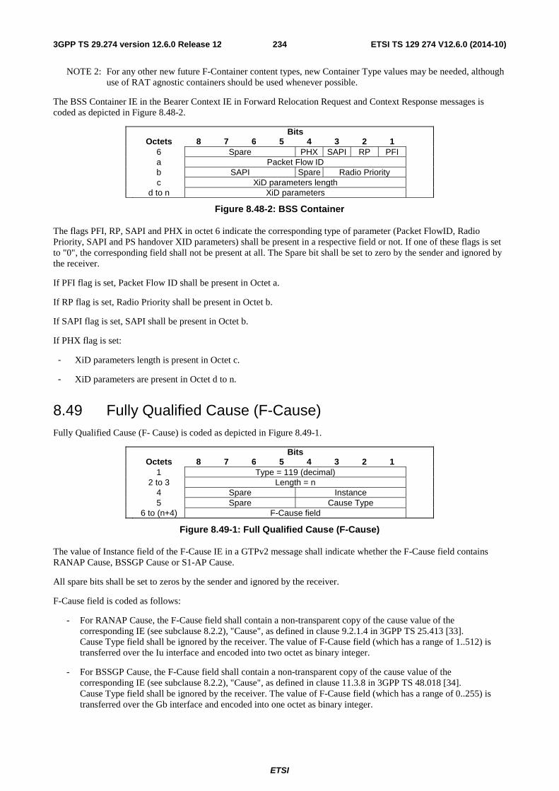
ETSI
ETSI TS 129 274 V12.6.0 (2014-10)2343GPP TS 29.274 version 12.6.0 Release 12
NOTE 2: For any other new future F-Container content types, new Container Type values may be needed, although use of RAT agnostic containers should be used whenever possible.
The BSS Container IE in the Bearer Context IE in Forward Relocation Request and Context Response messages is coded as depicted in Figure 8.48-2.
Bits Octets 8 7 6 5 4 3 2 1 6 Spare PHX SAPI RP PFI a Packet Flow ID b SAPI Spare Radio Priority c XiD parameters length d to n XiD parameters
Figure 8.48-2: BSS Container
The flags PFI, RP, SAPI and PHX in octet 6 indicate the corresponding type of parameter (Packet FlowID, Radio Priority, SAPI and PS handover XID parameters) shall be present in a respective field or not. If one of these flags is set to "0", the corresponding field shall not be present at all. The Spare bit shall be set to zero by the sender and ignored by the receiver.
If PFI flag is set, Packet Flow ID shall be present in Octet a.
If RP flag is set, Radio Priority shall be present in Octet b.
If SAPI flag is set, SAPI shall be present in Octet b.
If PHX flag is set:
- XiD parameters length is present in Octet c.
- XiD parameters are present in Octet d to n.
8.49 Fully Qualified Cause (F-Cause) Fully Qualified Cause (F- Cause) is coded as depicted in Figure 8.49-1.
Bits Octets 8 7 6 5 4 3 2 1 1 Type = 119 (decimal) 2 to 3 Length = n 4 Spare Instance 5 Spare Cause Type 6 to (n+4) F-Cause field
Figure 8.49-1: Full Qualified Cause (F-Cause)
The value of Instance field of the F-Cause IE in a GTPv2 message shall indicate whether the F-Cause field contains RANAP Cause, BSSGP Cause or S1-AP Cause.
All spare bits shall be set to zeros by the sender and ignored by the receiver.
F-Cause field is coded as follows:
- For RANAP Cause, the F-Cause field shall contain a non-transparent copy of the cause value of the corresponding IE (see subclause 8.2.2), "Cause", as defined in clause 9.2.1.4 in 3GPP TS 25.413 [33]. Cause Type field shall be ignored by the receiver. The value of F-Cause field (which has a range of 1..512) is transferred over the Iu interface and encoded into two octet as binary integer.
- For BSSGP Cause, the F-Cause field shall contain a non-transparent copy of the cause value of the corresponding IE (see subclause 8.2.2), "Cause", as defined in clause 11.3.8 in 3GPP TS 48.018 [34]. Cause Type field shall be ignored by the receiver. The value of F-Cause field (which has a range of 0..255) is transferred over the Gb interface and encoded into one octet as binary integer.
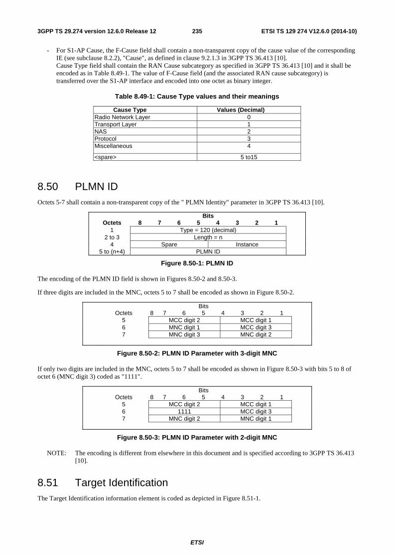
ETSI
ETSI TS 129 274 V12.6.0 (2014-10)2353GPP TS 29.274 version 12.6.0 Release 12
- For S1-AP Cause, the F-Cause field shall contain a non-transparent copy of the cause value of the corresponding IE (see subclause 8.2.2), "Cause", as defined in clause 9.2.1.3 in 3GPP TS 36.413 [10]. Cause Type field shall contain the RAN Cause subcategory as specified in 3GPP TS 36.413 [10] and it shall be encoded as in Table 8.49-1. The value of F-Cause field (and the associated RAN cause subcategory) is transferred over the S1-AP interface and encoded into one octet as binary integer.
Table 8.49-1: Cause Type values and their meanings
Cause Type Values (Decimal) Radio Network Layer 0 Transport Layer 1 NAS 2 Protocol 3 Miscellaneous 4
<spare> 5 to15
8.50 PLMN ID Octets 5-7 shall contain a non-transparent copy of the " PLMN Identity" parameter in 3GPP TS 36.413 [10].
Bits Octets 8 7 6 5 4 3 2 1 1 Type = 120 (decimal) 2 to 3 Length = n 4 Spare Instance 5 to (n+4) PLMN ID
Figure 8.50-1: PLMN ID
The encoding of the PLMN ID field is shown in Figures 8.50-2 and 8.50-3.
If three digits are included in the MNC, octets 5 to 7 shall be encoded as shown in Figure 8.50-2.
Bits Octets 8 7 6 5 4 3 2 1 5 MCC digit 2 MCC digit 1 6 MNC digit 1 MCC digit 3 7 MNC digit 3 MNC digit 2
Figure 8.50-2: PLMN ID Parameter with 3-digit MNC
If only two digits are included in the MNC, octets 5 to 7 shall be encoded as shown in Figure 8.50-3 with bits 5 to 8 of octet 6 (MNC digit 3) coded as "1111".
Bits Octets 8 7 6 5 4 3 2 1 5 MCC digit 2 MCC digit 1 6 1111 MCC digit 3 7 MNC digit 2 MNC digit 1
Figure 8.50-3: PLMN ID Parameter with 2-digit MNC
NOTE: The encoding is different from elsewhere in this document and is specified according to 3GPP TS 36.413 [10].
8.51 Target Identification The Target Identification information element is coded as depicted in Figure 8.51-1.
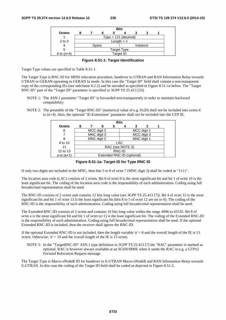
ETSI
ETSI TS 129 274 V12.6.0 (2014-10)2363GPP TS 29.274 version 12.6.0 Release 12
Bits Octets 8 7 6 5 4 3 2 1 1 Type = 121 (decimal) 2 to 3 Length = n 4 Spare Instance 5 Target Type 6 to (n+4) Target ID
Figure 8.51-1: Target Identification
Target Type values are specified in Table 8.51-1.
The Target Type is RNC ID for SRNS relocation procedure, handover to UTRAN and RAN Information Relay towards UTRAN or GERAN operating in GERAN Iu mode. In this case the "Target ID" field shall contain a non-transparent copy of the corresponding IEs (see subclause 8.2.2) and be encoded as specified in Figure 8.51-1a below. The "Target RNC-ID" part of the "Target ID" parameter is specified in 3GPP TS 25.413 [33].
NOTE 1: The ASN.1 parameter "Target ID" is forwarded non-transparently in order to maintain backward compatibility.
NOTE 2: The preamble of the "Target RNC-ID" (numerical value of e.g. 0x20) shall not be included into octets 6 to (n+4). Also, the optional "iE-Extensions" parameter shall not be included into the GTP IE.
Bits Octets 8 7 6 5 4 3 2 1 6 MCC digit 2 MCC digit 1 7 MNC digit 3 MCC digit 3 8 MNC digit 2 MNC digit 1 9 to 10 LAC 11 RAC (see NOTE 3) 12 to 13 RNC-ID a to (a+1) Extended RNC-ID (optional)
Figure 8.51-1a: Target ID for Type RNC ID
If only two digits are included in the MNC, then bits 5 to 8 of octet 7 (MNC digit 3) shall be coded as "1111".
The location area code (LAC) consists of 2 octets. Bit 8 of octet 9 is the most significant bit and bit 1 of octet 10 is the least significant bit. The coding of the location area code is the responsibility of each administration. Coding using full hexadecimal representation shall be used.
The RNC-ID consists of 2 octets and contains 12 bits long value (see 3GPP TS 25.413 [7]). Bit 4 of octet 12 is the most significant bit and bit 1 of octet 13 is the least significant bit (bits 8 to 5 of octet 12 are set to 0). The coding of the RNC-ID is the responsibility of each administration. Coding using full hexadecimal representation shall be used.
The Extended RNC-ID consists of 2 octets and contains 16 bits long value within the range 4096 to 65535. Bit 8 of octet a is the most significant bit and bit 1 of octet (a+1) is the least significant bit. The coding of the Extended RNC-ID is the responsibility of each administration. Coding using full hexadecimal representation shall be used. If the optional Extended RNC-ID is included, then the receiver shall ignore the RNC-ID.
If the optional Extended RNC-ID is not included, then the length variable 'n' = 8 and the overall length of the IE is 13 octets. Otherwise, 'n' = 10 and the overall length of the IE is 15 octets.
NOTE 3: In the "TargetRNC-ID" ASN.1 type definition in 3GPP TS 25.413 [7] the "RAC" parameter is marked as optional. RAC is however always available at an SGSN/MME when it sends the RAC in e.g. a GTPv2 Forward Relocation Request message.
The Target Type is Macro eNodeB ID for handover to E-UTRAN Macro eNodeB and RAN Information Relay towards E-UTRAN. In this case the coding of the Target ID field shall be coded as depicted in Figure 8.51-2.
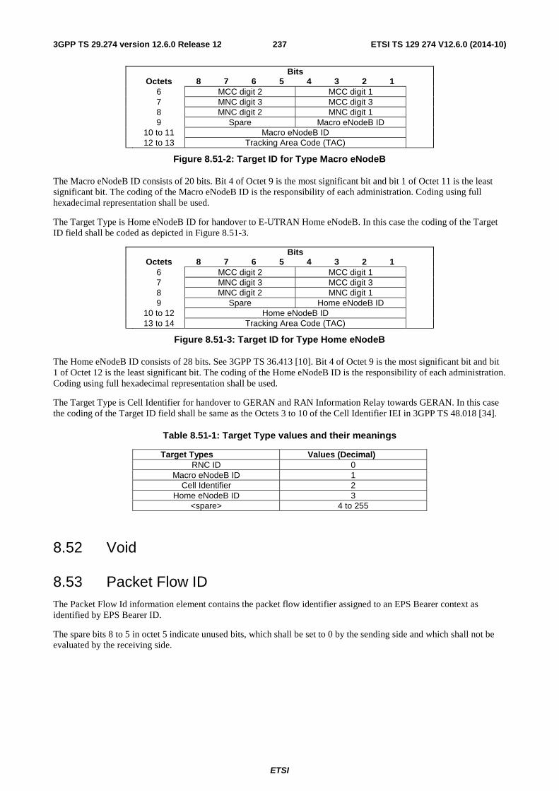
ETSI
ETSI TS 129 274 V12.6.0 (2014-10)2373GPP TS 29.274 version 12.6.0 Release 12
Bits Octets 8 7 6 5 4 3 2 1 6 MCC digit 2 MCC digit 1 7 MNC digit 3 MCC digit 3 8 MNC digit 2 MNC digit 1 9 Spare Macro eNodeB ID 10 to 11 Macro eNodeB ID 12 to 13 Tracking Area Code (TAC)
Figure 8.51-2: Target ID for Type Macro eNodeB
The Macro eNodeB ID consists of 20 bits. Bit 4 of Octet 9 is the most significant bit and bit 1 of Octet 11 is the least significant bit. The coding of the Macro eNodeB ID is the responsibility of each administration. Coding using full hexadecimal representation shall be used.
The Target Type is Home eNodeB ID for handover to E-UTRAN Home eNodeB. In this case the coding of the Target ID field shall be coded as depicted in Figure 8.51-3.
Bits Octets 8 7 6 5 4 3 2 1 6 MCC digit 2 MCC digit 1 7 MNC digit 3 MCC digit 3 8 MNC digit 2 MNC digit 1 9 Spare Home eNodeB ID 10 to 12 Home eNodeB ID 13 to 14 Tracking Area Code (TAC)
Figure 8.51-3: Target ID for Type Home eNodeB
The Home eNodeB ID consists of 28 bits. See 3GPP TS 36.413 [10]. Bit 4 of Octet 9 is the most significant bit and bit 1 of Octet 12 is the least significant bit. The coding of the Home eNodeB ID is the responsibility of each administration. Coding using full hexadecimal representation shall be used.
The Target Type is Cell Identifier for handover to GERAN and RAN Information Relay towards GERAN. In this case the coding of the Target ID field shall be same as the Octets 3 to 10 of the Cell Identifier IEI in 3GPP TS 48.018 [34].
Table 8.51-1: Target Type values and their meanings
Target Types Values (Decimal) RNC ID 0
Macro eNodeB ID 1 Cell Identifier 2
Home eNodeB ID 3 <spare> 4 to 255
8.52 Void
8.53 Packet Flow ID The Packet Flow Id information element contains the packet flow identifier assigned to an EPS Bearer context as identified by EPS Bearer ID.
The spare bits 8 to 5 in octet 5 indicate unused bits, which shall be set to 0 by the sending side and which shall not be evaluated by the receiving side.
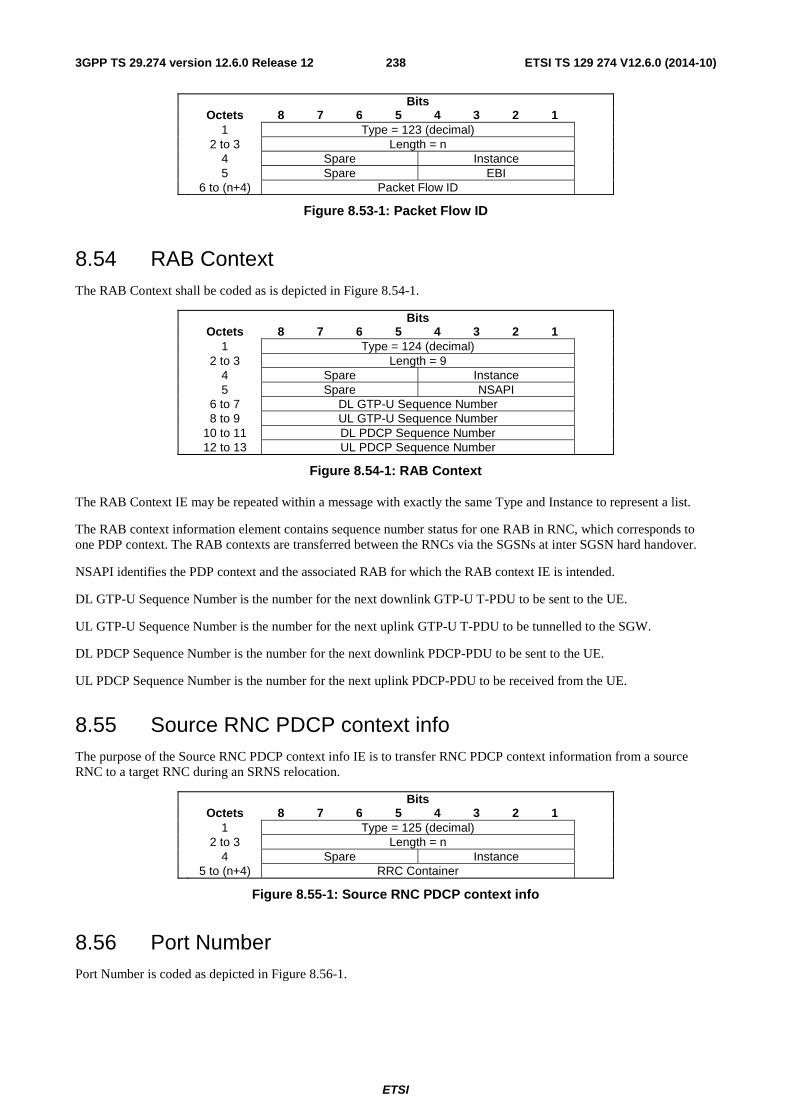
ETSI
ETSI TS 129 274 V12.6.0 (2014-10)2383GPP TS 29.274 version 12.6.0 Release 12
Bits Octets 8 7 6 5 4 3 2 1 1 Type = 123 (decimal) 2 to 3 Length = n 4 Spare Instance 5 Spare EBI 6 to (n+4) Packet Flow ID
Figure 8.53-1: Packet Flow ID
8.54 RAB Context The RAB Context shall be coded as is depicted in Figure 8.54-1.
Bits Octets 8 7 6 5 4 3 2 1 1 Type = 124 (decimal) 2 to 3 Length = 9 4 Spare Instance 5 Spare NSAPI 6 to 7 DL GTP-U Sequence Number 8 to 9 UL GTP-U Sequence Number 10 to 11 DL PDCP Sequence Number 12 to 13 UL PDCP Sequence Number
Figure 8.54-1: RAB Context
The RAB Context IE may be repeated within a message with exactly the same Type and Instance to represent a list.
The RAB context information element contains sequence number status for one RAB in RNC, which corresponds to one PDP context. The RAB contexts are transferred between the RNCs via the SGSNs at inter SGSN hard handover.
NSAPI identifies the PDP context and the associated RAB for which the RAB context IE is intended.
DL GTP-U Sequence Number is the number for the next downlink GTP-U T-PDU to be sent to the UE.
UL GTP-U Sequence Number is the number for the next uplink GTP-U T-PDU to be tunnelled to the SGW.
DL PDCP Sequence Number is the number for the next downlink PDCP-PDU to be sent to the UE.
UL PDCP Sequence Number is the number for the next uplink PDCP-PDU to be received from the UE.
8.55 Source RNC PDCP context info The purpose of the Source RNC PDCP context info IE is to transfer RNC PDCP context information from a source RNC to a target RNC during an SRNS relocation.
Bits Octets 8 7 6 5 4 3 2 1 1 Type = 125 (decimal) 2 to 3 Length = n 4 Spare Instance 5 to (n+4) RRC Container
Figure 8.55-1: Source RNC PDCP context info
8.56 Port Number Port Number is coded as depicted in Figure 8.56-1.
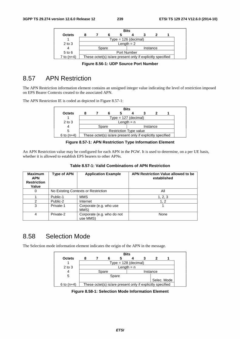
ETSI
ETSI TS 129 274 V12.6.0 (2014-10)2393GPP TS 29.274 version 12.6.0 Release 12
Bits Octets 8 7 6 5 4 3 2 1 1 Type = 126 (decimal) 2 to 3 Length = 2 4 Spare Instance 5 to 6 Port Number 7 to (n+4) These octet(s) is/are present only if explicitly specified
Figure 8.56-1: UDP Source Port Number
8.57 APN Restriction The APN Restriction information element contains an unsigned integer value indicating the level of restriction imposed on EPS Bearer Contexts created to the associated APN.
The APN Restriction IE is coded as depicted in Figure 8.57-1:
Bits Octets 8 7 6 5 4 3 2 1 1 Type = 127 (decimal) 2 to 3 Length = n 4 Spare Instance 5 Restriction Type value 6 to (n+4) These octet(s) is/are present only if explicitly specified
Figure 8.57-1: APN Restriction Type Information Element
An APN Restriction value may be configured for each APN in the PGW. It is used to determine, on a per UE basis, whether it is allowed to establish EPS bearers to other APNs.
Table 8.57-1: Valid Combinations of APN Restriction
Maximum APN
Restriction Value
Type of APN Application Example APN Restriction Value allowed to be established
0 No Existing Contexts or Restriction All
1 Public-1 MMS 1, 2, 3 2 Public-2 Internet 1, 2 3 Private-1 Corporate (e.g. who use
MMS) 1
4 Private-2 Corporate (e.g. who do not use MMS)
None
8.58 Selection Mode The Selection mode information element indicates the origin of the APN in the message.
Bits Octets 8 7 6 5 4 3 2 1 1 Type = 128 (decimal) 2 to 3 Length = n 4 Spare Instance 5 Spare
Selec. Mode
6 to (n+4) These octet(s) is/are present only if explicitly specified
Figure 8.58-1: Selection Mode Information Element
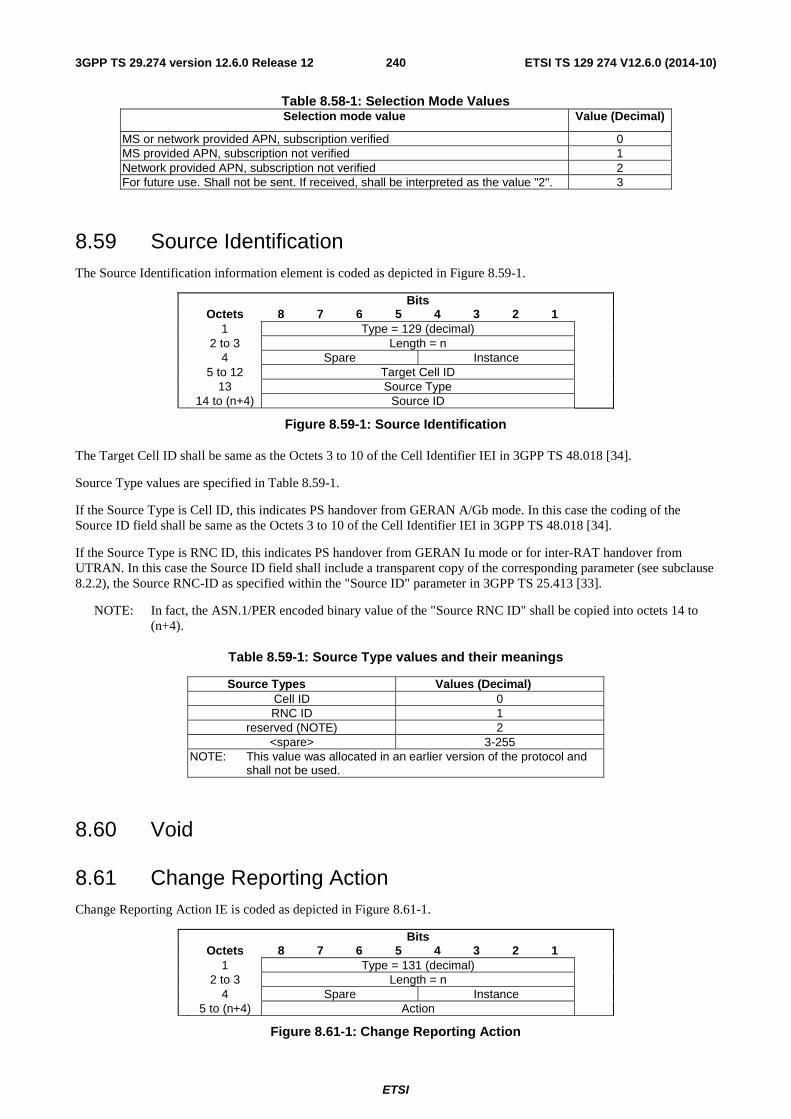
ETSI
ETSI TS 129 274 V12.6.0 (2014-10)2403GPP TS 29.274 version 12.6.0 Release 12
Table 8.58-1: Selection Mode ValuesSelection mode value Value (Decimal)
MS or network provided APN, subscription verified 0 MS provided APN, subscription not verified 1 Network provided APN, subscription not verified 2 For future use. Shall not be sent. If received, shall be interpreted as the value "2". 3
8.59 Source Identification The Source Identification information element is coded as depicted in Figure 8.59-1.
Bits Octets 8 7 6 5 4 3 2 1 1 Type = 129 (decimal) 2 to 3 Length = n 4 Spare Instance 5 to 12 Target Cell ID 13 Source Type 14 to (n+4) Source ID
Figure 8.59-1: Source Identification
The Target Cell ID shall be same as the Octets 3 to 10 of the Cell Identifier IEI in 3GPP TS 48.018 [34].
Source Type values are specified in Table 8.59-1.
If the Source Type is Cell ID, this indicates PS handover from GERAN A/Gb mode. In this case the coding of the Source ID field shall be same as the Octets 3 to 10 of the Cell Identifier IEI in 3GPP TS 48.018 [34].
If the Source Type is RNC ID, this indicates PS handover from GERAN Iu mode or for inter-RAT handover from UTRAN. In this case the Source ID field shall include a transparent copy of the corresponding parameter (see subclause 8.2.2), the Source RNC-ID as specified within the "Source ID" parameter in 3GPP TS 25.413 [33].
NOTE: In fact, the ASN.1/PER encoded binary value of the "Source RNC ID" shall be copied into octets 14 to (n+4).
Table 8.59-1: Source Type values and their meanings
Source Types Values (Decimal) Cell ID 0 RNC ID 1
reserved (NOTE) 2 <spare> 3-255
NOTE: This value was allocated in an earlier version of the protocol and shall not be used.
8.60 Void
8.61 Change Reporting Action Change Reporting Action IE is coded as depicted in Figure 8.61-1.
Bits Octets 8 7 6 5 4 3 2 1 1 Type = 131 (decimal) 2 to 3 Length = n 4 Spare Instance 5 to (n+4) Action
Figure 8.61-1: Change Reporting Action
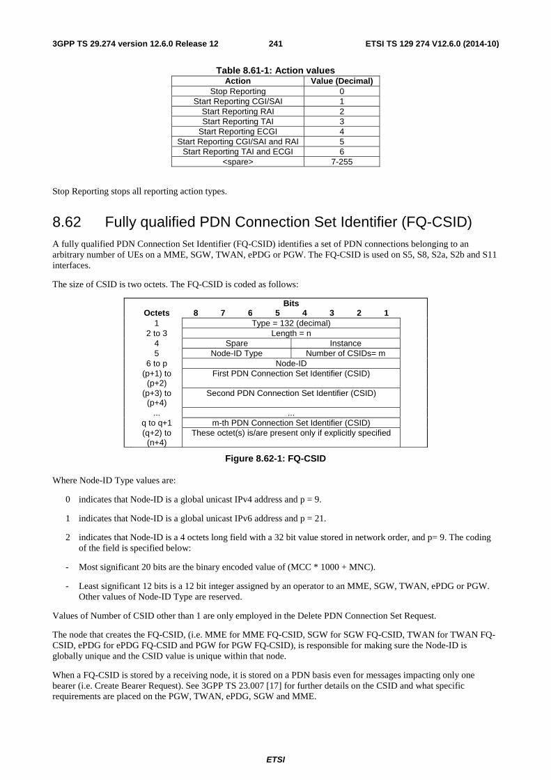
ETSI
ETSI TS 129 274 V12.6.0 (2014-10)2413GPP TS 29.274 version 12.6.0 Release 12
Table 8.61-1: Action valuesAction Value (Decimal)
Stop Reporting 0 Start Reporting CGI/SAI 1
Start Reporting RAI 2 Start Reporting TAI 3
Start Reporting ECGI 4 Start Reporting CGI/SAI and RAI 5
Start Reporting TAI and ECGI 6 <spare> 7-255
Stop Reporting stops all reporting action types.
8.62 Fully qualified PDN Connection Set Identifier (FQ-CSID) A fully qualified PDN Connection Set Identifier (FQ-CSID) identifies a set of PDN connections belonging to an arbitrary number of UEs on a MME, SGW, TWAN, ePDG or PGW. The FQ-CSID is used on S5, S8, S2a, S2b and S11 interfaces.
The size of CSID is two octets. The FQ-CSID is coded as follows:
Bits Octets 8 7 6 5 4 3 2 1 1 Type = 132 (decimal) 2 to 3 Length = n 4 Spare Instance 5 Node-ID Type Number of CSIDs= m 6 to p Node-ID (p+1) to
(p+2) First PDN Connection Set Identifier (CSID)
(p+3) to (p+4)
Second PDN Connection Set Identifier (CSID)
... ... q to q+1 m-th PDN Connection Set Identifier (CSID) (q+2) to
(n+4) These octet(s) is/are present only if explicitly specified
Figure 8.62-1: FQ-CSID
Where Node-ID Type values are:
0 indicates that Node-ID is a global unicast IPv4 address and p = 9.
1 indicates that Node-ID is a global unicast IPv6 address and p = 21.
2 indicates that Node-ID is a 4 octets long field with a 32 bit value stored in network order, and p= 9. The coding of the field is specified below:
- Most significant 20 bits are the binary encoded value of (MCC * 1000 + MNC).
- Least significant 12 bits is a 12 bit integer assigned by an operator to an MME, SGW, TWAN, ePDG or PGW. Other values of Node-ID Type are reserved.
Values of Number of CSID other than 1 are only employed in the Delete PDN Connection Set Request.
The node that creates the FQ-CSID, (i.e. MME for MME FQ-CSID, SGW for SGW FQ-CSID, TWAN for TWAN FQ-CSID, ePDG for ePDG FQ-CSID and PGW for PGW FQ-CSID), is responsible for making sure the Node-ID is globally unique and the CSID value is unique within that node.
When a FQ-CSID is stored by a receiving node, it is stored on a PDN basis even for messages impacting only one bearer (i.e. Create Bearer Request). See 3GPP TS 23.007 [17] for further details on the CSID and what specific requirements are placed on the PGW, TWAN, ePDG, SGW and MME.
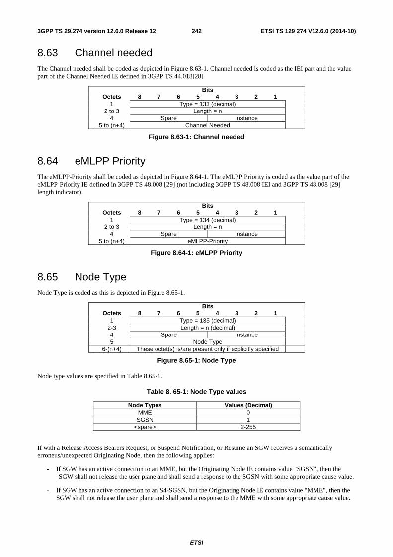
ETSI
ETSI TS 129 274 V12.6.0 (2014-10)2423GPP TS 29.274 version 12.6.0 Release 12
8.63 Channel needed The Channel needed shall be coded as depicted in Figure 8.63-1. Channel needed is coded as the IEI part and the value part of the Channel Needed IE defined in 3GPP TS 44.018[28]
Bits Octets 8 7 6 5 4 3 2 1 1 Type = 133 (decimal) 2 to 3 Length = n 4 Spare Instance 5 to (n+4) Channel Needed
Figure 8.63-1: Channel needed
8.64 eMLPP Priority The eMLPP-Priority shall be coded as depicted in Figure 8.64-1. The eMLPP Priority is coded as the value part of the eMLPP-Priority IE defined in 3GPP TS 48.008 [29] (not including 3GPP TS 48.008 IEI and 3GPP TS 48.008 [29] length indicator).
Bits Octets 8 7 6 5 4 3 2 1 1 Type = 134 (decimal) 2 to 3 Length = n 4 Spare Instance 5 to (n+4) eMLPP-Priority
Figure 8.64-1: eMLPP Priority
8.65 Node Type Node Type is coded as this is depicted in Figure 8.65-1.
Bits Octets 8 7 6 5 4 3 2 1 1 Type = 135 (decimal) 2-3 Length = n (decimal) 4 Spare Instance 5 Node Type 6-(n+4) These octet(s) is/are present only if explicitly specified
Figure 8.65-1: Node Type
Node type values are specified in Table 8.65-1.
Table 8. 65-1: Node Type values
Node Types Values (Decimal) MME 0 SGSN 1
<spare> 2-255
If with a Release Access Bearers Request, or Suspend Notification, or Resume an SGW receives a semantically erroneus/unexpected Originating Node, then the following applies:
- If SGW has an active connection to an MME, but the Originating Node IE contains value "SGSN", then the SGW shall not release the user plane and shall send a response to the SGSN with some appropriate cause value.
- If SGW has an active connection to an S4-SGSN, but the Originating Node IE contains value "MME", then the SGW shall not release the user plane and shall send a response to the MME with some appropriate cause value.
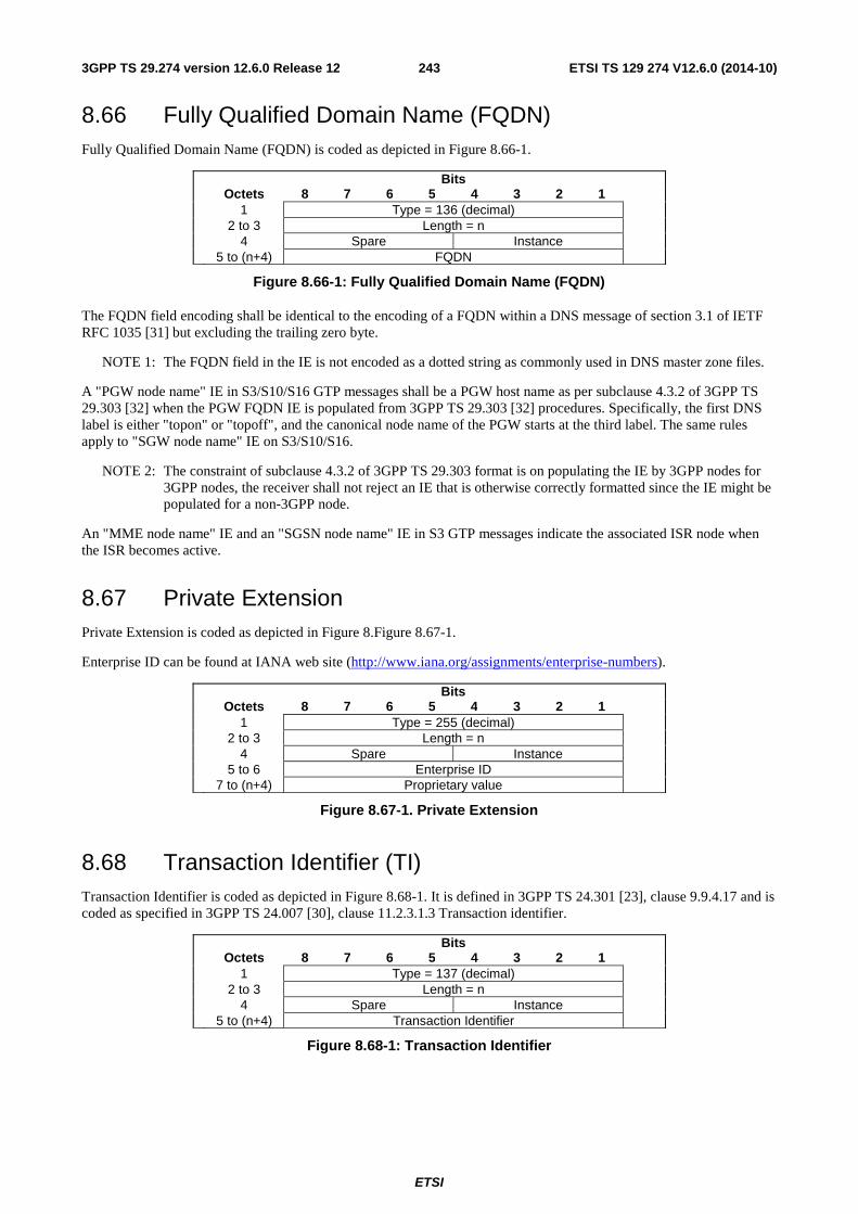
ETSI
ETSI TS 129 274 V12.6.0 (2014-10)2433GPP TS 29.274 version 12.6.0 Release 12
8.66 Fully Qualified Domain Name (FQDN) Fully Qualified Domain Name (FQDN) is coded as depicted in Figure 8.66-1.
Bits Octets 8 7 6 5 4 3 2 1 1 Type = 136 (decimal) 2 to 3 Length = n 4 Spare Instance 5 to (n+4) FQDN
Figure 8.66-1: Fully Qualified Domain Name (FQDN)
The FQDN field encoding shall be identical to the encoding of a FQDN within a DNS message of section 3.1 of IETF RFC 1035 [31] but excluding the trailing zero byte.
NOTE 1: The FQDN field in the IE is not encoded as a dotted string as commonly used in DNS master zone files.
A "PGW node name" IE in S3/S10/S16 GTP messages shall be a PGW host name as per subclause 4.3.2 of 3GPP TS 29.303 [32] when the PGW FQDN IE is populated from 3GPP TS 29.303 [32] procedures. Specifically, the first DNS label is either "topon" or "topoff", and the canonical node name of the PGW starts at the third label. The same rules apply to "SGW node name" IE on S3/S10/S16.
NOTE 2: The constraint of subclause 4.3.2 of 3GPP TS 29.303 format is on populating the IE by 3GPP nodes for 3GPP nodes, the receiver shall not reject an IE that is otherwise correctly formatted since the IE might be populated for a non-3GPP node.
An "MME node name" IE and an "SGSN node name" IE in S3 GTP messages indicate the associated ISR node when the ISR becomes active.
8.67 Private Extension Private Extension is coded as depicted in Figure 8.Figure 8.67-1.
Enterprise ID can be found at IANA web site (http://www.iana.org/assignments/enterprise-numbers).
Bits Octets 8 7 6 5 4 3 2 1 1 Type = 255 (decimal) 2 to 3 Length = n 4 Spare Instance 5 to 6 Enterprise ID 7 to (n+4) Proprietary value
Figure 8.67-1. Private Extension
8.68 Transaction Identifier (TI) Transaction Identifier is coded as depicted in Figure 8.68-1. It is defined in 3GPP TS 24.301 [23], clause 9.9.4.17 and is coded as specified in 3GPP TS 24.007 [30], clause 11.2.3.1.3 Transaction identifier.
Bits Octets 8 7 6 5 4 3 2 1 1 Type = 137 (decimal) 2 to 3 Length = n 4 Spare Instance 5 to (n+4) Transaction Identifier
Figure 8.68-1: Transaction Identifier
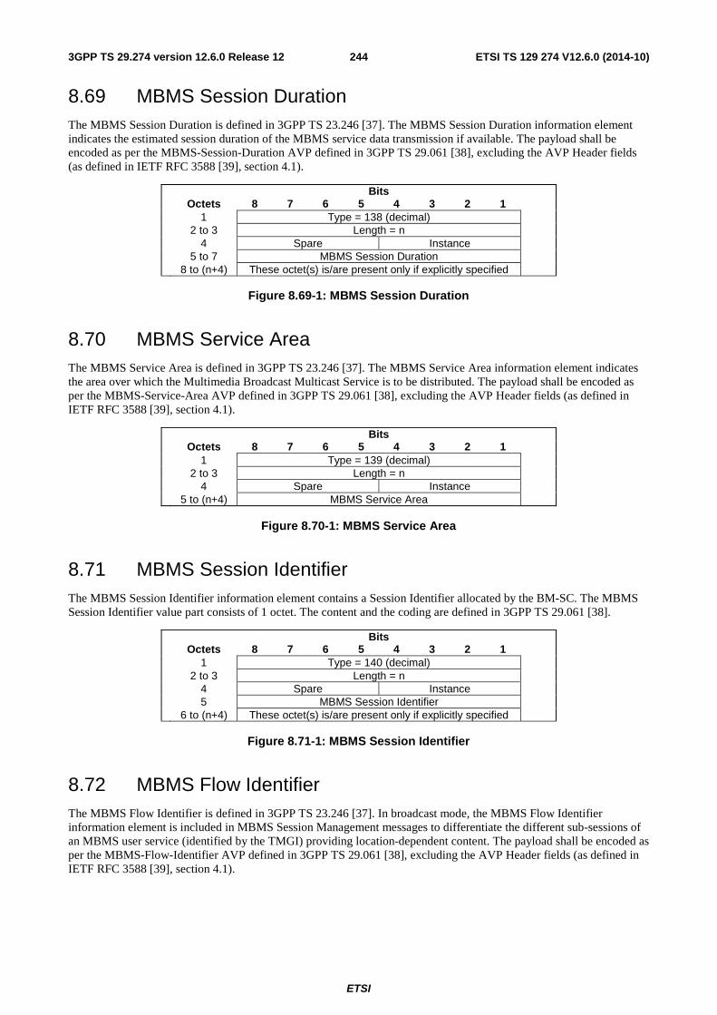
ETSI
ETSI TS 129 274 V12.6.0 (2014-10)2443GPP TS 29.274 version 12.6.0 Release 12
8.69 MBMS Session Duration The MBMS Session Duration is defined in 3GPP TS 23.246 [37]. The MBMS Session Duration information element indicates the estimated session duration of the MBMS service data transmission if available. The payload shall be encoded as per the MBMS-Session-Duration AVP defined in 3GPP TS 29.061 [38], excluding the AVP Header fields (as defined in IETF RFC 3588 [39], section 4.1).
Bits Octets 8 7 6 5 4 3 2 1 1 Type = 138 (decimal) 2 to 3 Length = n 4 Spare Instance 5 to 7 MBMS Session Duration 8 to (n+4) These octet(s) is/are present only if explicitly specified
Figure 8.69-1: MBMS Session Duration
8.70 MBMS Service Area The MBMS Service Area is defined in 3GPP TS 23.246 [37]. The MBMS Service Area information element indicates the area over which the Multimedia Broadcast Multicast Service is to be distributed. The payload shall be encoded as per the MBMS-Service-Area AVP defined in 3GPP TS 29.061 [38], excluding the AVP Header fields (as defined in IETF RFC 3588 [39], section 4.1).
Bits Octets 8 7 6 5 4 3 2 1 1 Type = 139 (decimal) 2 to 3 Length = n 4 Spare Instance 5 to (n+4) MBMS Service Area
Figure 8.70-1: MBMS Service Area
8.71 MBMS Session Identifier The MBMS Session Identifier information element contains a Session Identifier allocated by the BM-SC. The MBMS Session Identifier value part consists of 1 octet. The content and the coding are defined in 3GPP TS 29.061 [38].
Bits Octets 8 7 6 5 4 3 2 1 1 Type = 140 (decimal) 2 to 3 Length = n 4 Spare Instance 5 MBMS Session Identifier 6 to (n+4) These octet(s) is/are present only if explicitly specified
Figure 8.71-1: MBMS Session Identifier
8.72 MBMS Flow Identifier The MBMS Flow Identifier is defined in 3GPP TS 23.246 [37]. In broadcast mode, the MBMS Flow Identifier information element is included in MBMS Session Management messages to differentiate the different sub-sessions of an MBMS user service (identified by the TMGI) providing location-dependent content. The payload shall be encoded as per the MBMS-Flow-Identifier AVP defined in 3GPP TS 29.061 [38], excluding the AVP Header fields (as defined in IETF RFC 3588 [39], section 4.1).
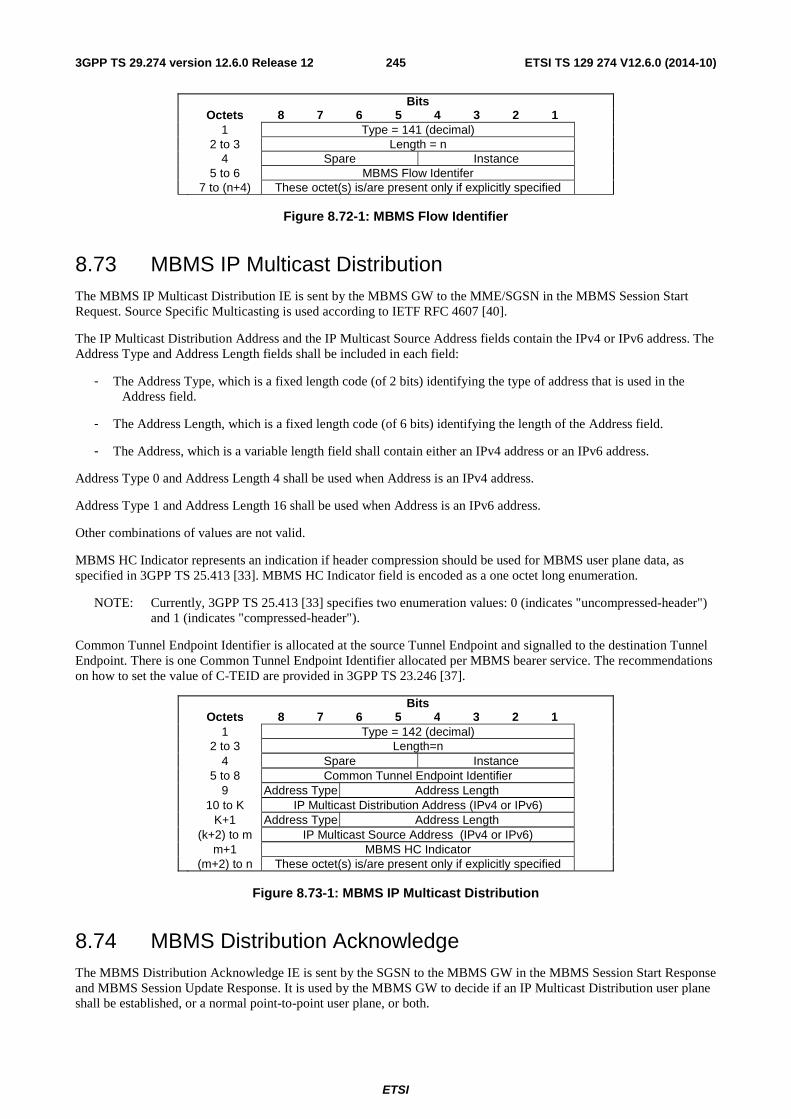
ETSI
ETSI TS 129 274 V12.6.0 (2014-10)2453GPP TS 29.274 version 12.6.0 Release 12
Bits Octets 8 7 6 5 4 3 2 1 1 Type = 141 (decimal) 2 to 3 Length = n 4 Spare Instance 5 to 6 MBMS Flow Identifer 7 to (n+4) These octet(s) is/are present only if explicitly specified
Figure 8.72-1: MBMS Flow Identifier
8.73 MBMS IP Multicast Distribution The MBMS IP Multicast Distribution IE is sent by the MBMS GW to the MME/SGSN in the MBMS Session Start Request. Source Specific Multicasting is used according to IETF RFC 4607 [40].
The IP Multicast Distribution Address and the IP Multicast Source Address fields contain the IPv4 or IPv6 address. The Address Type and Address Length fields shall be included in each field:
- The Address Type, which is a fixed length code (of 2 bits) identifying the type of address that is used in the Address field.
- The Address Length, which is a fixed length code (of 6 bits) identifying the length of the Address field.
- The Address, which is a variable length field shall contain either an IPv4 address or an IPv6 address.
Address Type 0 and Address Length 4 shall be used when Address is an IPv4 address.
Address Type 1 and Address Length 16 shall be used when Address is an IPv6 address.
Other combinations of values are not valid.
MBMS HC Indicator represents an indication if header compression should be used for MBMS user plane data, as specified in 3GPP TS 25.413 [33]. MBMS HC Indicator field is encoded as a one octet long enumeration.
NOTE: Currently, 3GPP TS 25.413 [33] specifies two enumeration values: 0 (indicates "uncompressed-header") and 1 (indicates "compressed-header").
Common Tunnel Endpoint Identifier is allocated at the source Tunnel Endpoint and signalled to the destination Tunnel Endpoint. There is one Common Tunnel Endpoint Identifier allocated per MBMS bearer service. The recommendations on how to set the value of C-TEID are provided in 3GPP TS 23.246 [37].
Bits Octets 8 7 6 5 4 3 2 1 1 Type = 142 (decimal) 2 to 3 Length=n 4 Spare Instance 5 to 8 Common Tunnel Endpoint Identifier 9 Address Type Address Length 10 to K IP Multicast Distribution Address (IPv4 or IPv6) K+1 Address Type Address Length (k+2) to m IP Multicast Source Address (IPv4 or IPv6) m+1 MBMS HC Indicator (m+2) to n These octet(s) is/are present only if explicitly specified
Figure 8.73-1: MBMS IP Multicast Distribution
8.74 MBMS Distribution Acknowledge The MBMS Distribution Acknowledge IE is sent by the SGSN to the MBMS GW in the MBMS Session Start Response and MBMS Session Update Response. It is used by the MBMS GW to decide if an IP Multicast Distribution user plane shall be established, or a normal point-to-point user plane, or both.
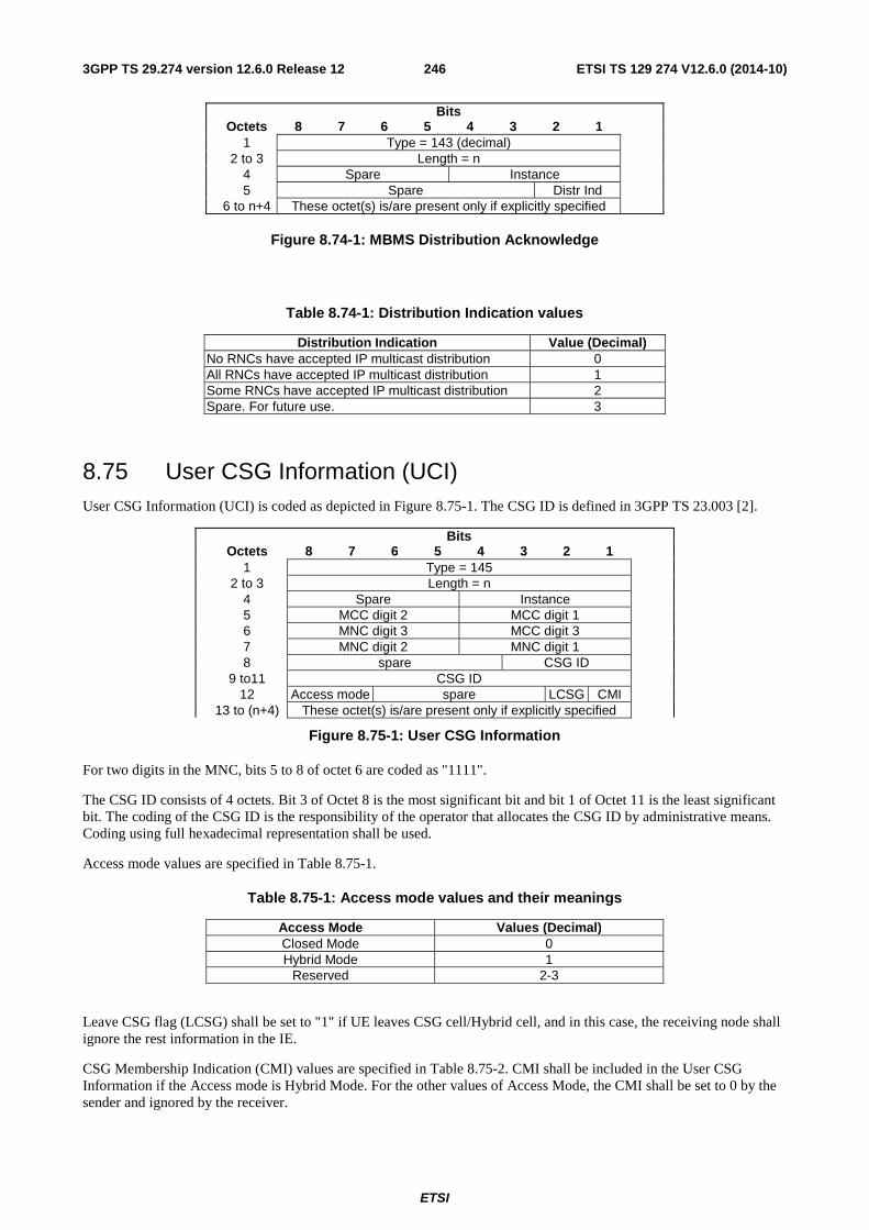
ETSI
ETSI TS 129 274 V12.6.0 (2014-10)2463GPP TS 29.274 version 12.6.0 Release 12
Bits Octets 8 7 6 5 4 3 2 1 1 Type = 143 (decimal) 2 to 3 Length = n 4 Spare Instance 5 Spare Distr Ind 6 to n+4 These octet(s) is/are present only if explicitly specified
Figure 8.74-1: MBMS Distribution Acknowledge
Table 8.74-1: Distribution Indication values
Distribution Indication Value (Decimal) No RNCs have accepted IP multicast distribution 0 All RNCs have accepted IP multicast distribution 1 Some RNCs have accepted IP multicast distribution 2 Spare. For future use. 3
8.75 User CSG Information (UCI) User CSG Information (UCI) is coded as depicted in Figure 8.75-1. The CSG ID is defined in 3GPP TS 23.003 [2].
Bits Octets 8 7 6 5 4 3 2 1 1 Type = 145 2 to 3 Length = n 4 Spare Instance 5 MCC digit 2 MCC digit 1 6 MNC digit 3 MCC digit 3 7 MNC digit 2 MNC digit 1 8 spare CSG ID 9 to11 CSG ID 12 Access mode spare LCSG CMI 13 to (n+4) These octet(s) is/are present only if explicitly specified
Figure 8.75-1: User CSG Information
For two digits in the MNC, bits 5 to 8 of octet 6 are coded as "1111".
The CSG ID consists of 4 octets. Bit 3 of Octet 8 is the most significant bit and bit 1 of Octet 11 is the least significant bit. The coding of the CSG ID is the responsibility of the operator that allocates the CSG ID by administrative means. Coding using full hexadecimal representation shall be used.
Access mode values are specified in Table 8.75-1.
Table 8.75-1: Access mode values and their meanings
Access Mode Values (Decimal) Closed Mode 0 Hybrid Mode 1
Reserved 2-3
Leave CSG flag (LCSG) shall be set to "1" if UE leaves CSG cell/Hybrid cell, and in this case, the receiving node shall ignore the rest information in the IE.
CSG Membership Indication (CMI) values are specified in Table 8.75-2. CMI shall be included in the User CSG Information if the Access mode is Hybrid Mode. For the other values of Access Mode, the CMI shall be set to 0 by the sender and ignored by the receiver.
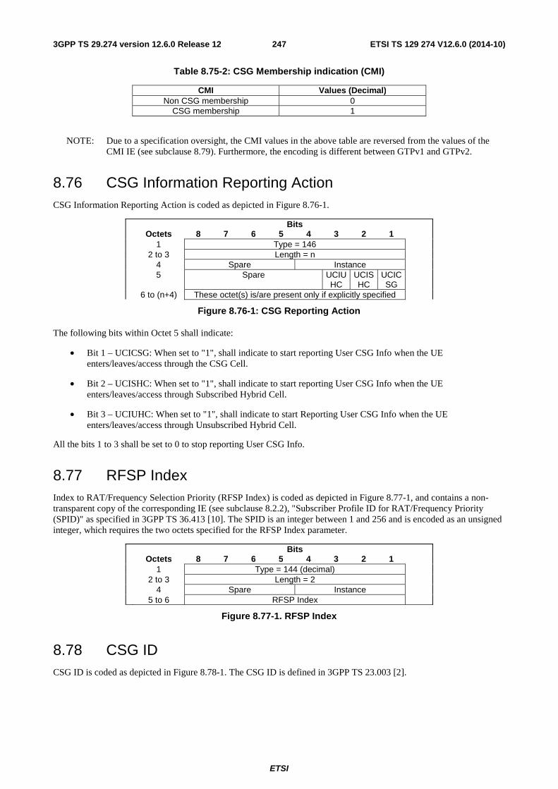
ETSI
ETSI TS 129 274 V12.6.0 (2014-10)2473GPP TS 29.274 version 12.6.0 Release 12
Table 8.75-2: CSG Membership indication (CMI)
CMI Values (Decimal) Non CSG membership 0
CSG membership 1
NOTE: Due to a specification oversight, the CMI values in the above table are reversed from the values of the CMI IE (see subclause 8.79). Furthermore, the encoding is different between GTPv1 and GTPv2.
8.76 CSG Information Reporting Action CSG Information Reporting Action is coded as depicted in Figure 8.76-1.
Bits Octets 8 7 6 5 4 3 2 1 1 Type = 146 2 to 3 Length = n 4 Spare Instance 5 Spare UCIU
HC UCISHC
UCICSG
6 to (n+4) These octet(s) is/are present only if explicitly specified
Figure 8.76-1: CSG Reporting Action
The following bits within Octet 5 shall indicate:
• Bit 1 – UCICSG: When set to "1", shall indicate to start reporting User CSG Info when the UE enters/leaves/access through the CSG Cell.
• Bit 2 – UCISHC: When set to "1", shall indicate to start reporting User CSG Info when the UE enters/leaves/access through Subscribed Hybrid Cell.
• Bit 3 – UCIUHC: When set to "1", shall indicate to start Reporting User CSG Info when the UE enters/leaves/access through Unsubscribed Hybrid Cell.
All the bits 1 to 3 shall be set to 0 to stop reporting User CSG Info.
8.77 RFSP Index Index to RAT/Frequency Selection Priority (RFSP Index) is coded as depicted in Figure 8.77-1, and contains a non-transparent copy of the corresponding IE (see subclause 8.2.2), "Subscriber Profile ID for RAT/Frequency Priority (SPID)" as specified in 3GPP TS 36.413 [10]. The SPID is an integer between 1 and 256 and is encoded as an unsigned integer, which requires the two octets specified for the RFSP Index parameter.
Bits Octets 8 7 6 5 4 3 2 1 1 Type = 144 (decimal) 2 to 3 Length = 2 4 Spare Instance 5 to 6 RFSP Index
Figure 8.77-1. RFSP Index
8.78 CSG ID CSG ID is coded as depicted in Figure 8.78-1. The CSG ID is defined in 3GPP TS 23.003 [2].
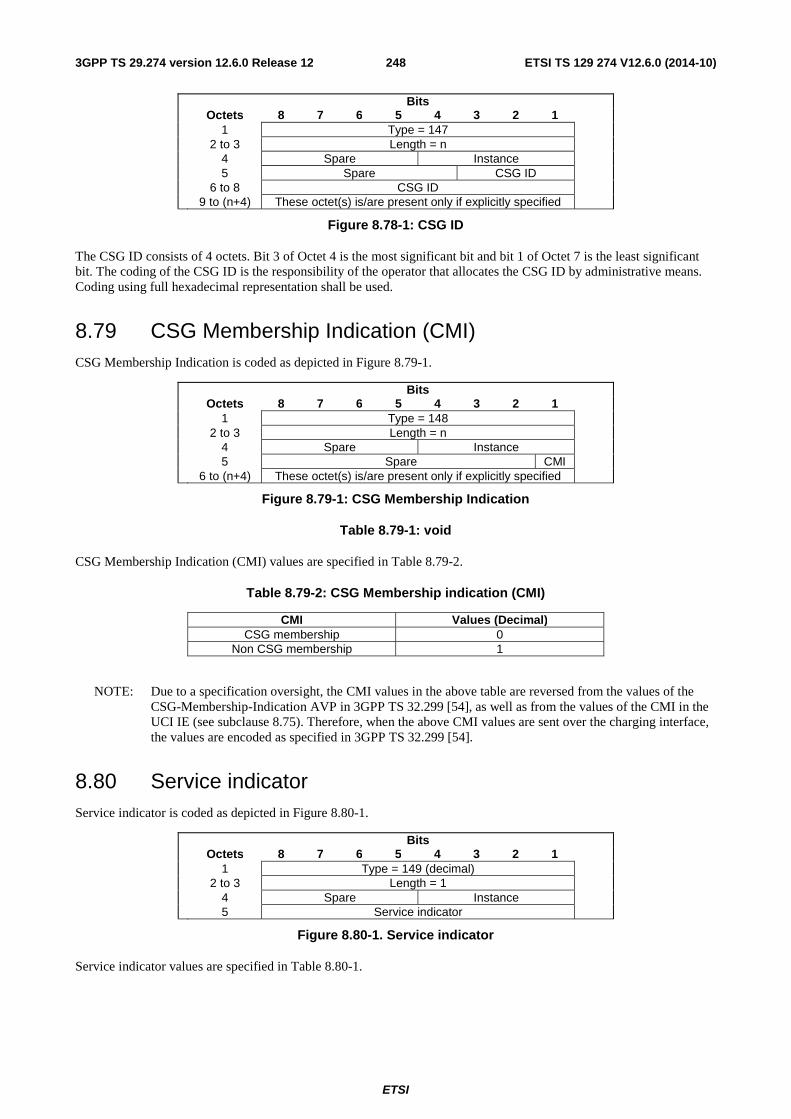
ETSI
ETSI TS 129 274 V12.6.0 (2014-10)2483GPP TS 29.274 version 12.6.0 Release 12
Bits Octets 8 7 6 5 4 3 2 1 1 Type = 147 2 to 3 Length = n 4 Spare Instance 5 Spare CSG ID 6 to 8 CSG ID 9 to (n+4) These octet(s) is/are present only if explicitly specified
Figure 8.78-1: CSG ID
The CSG ID consists of 4 octets. Bit 3 of Octet 4 is the most significant bit and bit 1 of Octet 7 is the least significant bit. The coding of the CSG ID is the responsibility of the operator that allocates the CSG ID by administrative means. Coding using full hexadecimal representation shall be used.
8.79 CSG Membership Indication (CMI) CSG Membership Indication is coded as depicted in Figure 8.79-1.
Bits Octets 8 7 6 5 4 3 2 1 1 Type = 148 2 to 3 Length = n 4 Spare Instance 5 Spare CMI 6 to (n+4) These octet(s) is/are present only if explicitly specified
Figure 8.79-1: CSG Membership Indication
Table 8.79-1: void
CSG Membership Indication (CMI) values are specified in Table 8.79-2.
Table 8.79-2: CSG Membership indication (CMI)
CMI Values (Decimal) CSG membership 0
Non CSG membership 1
NOTE: Due to a specification oversight, the CMI values in the above table are reversed from the values of the CSG-Membership-Indication AVP in 3GPP TS 32.299 [54], as well as from the values of the CMI in the UCI IE (see subclause 8.75). Therefore, when the above CMI values are sent over the charging interface, the values are encoded as specified in 3GPP TS 32.299 [54].
8.80 Service indicator Service indicator is coded as depicted in Figure 8.80-1.
Bits Octets 8 7 6 5 4 3 2 1 1 Type = 149 (decimal) 2 to 3 Length = 1 4 Spare Instance 5 Service indicator
Figure 8.80-1. Service indicator
Service indicator values are specified in Table 8.80-1.
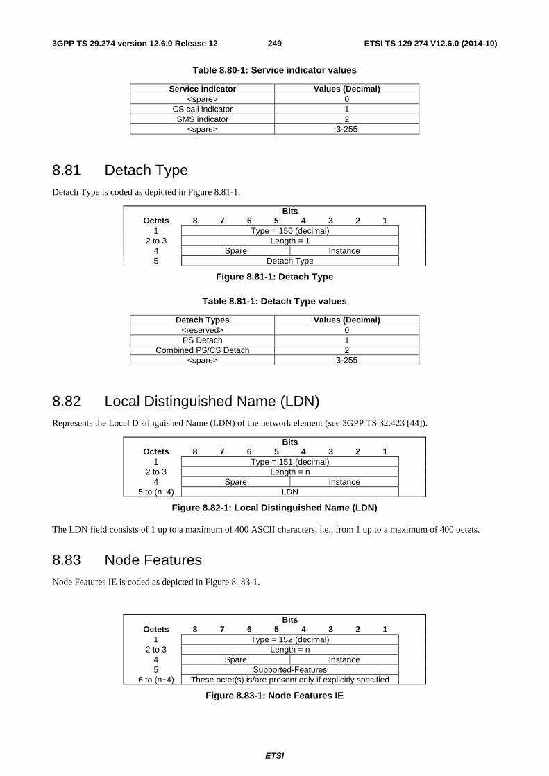
ETSI
ETSI TS 129 274 V12.6.0 (2014-10)2493GPP TS 29.274 version 12.6.0 Release 12
Table 8.80-1: Service indicator values
Service indicator Values (Decimal) <spare> 0
CS call indicator 1 SMS indicator 2
<spare> 3-255
8.81 Detach Type Detach Type is coded as depicted in Figure 8.81-1.
Bits Octets 8 7 6 5 4 3 2 1 1 Type = 150 (decimal) 2 to 3 Length = 1 4 Spare Instance 5 Detach Type
Figure 8.81-1: Detach Type
Table 8.81-1: Detach Type values
Detach Types Values (Decimal) <reserved> 0 PS Detach 1
Combined PS/CS Detach 2 <spare> 3-255
8.82 Local Distinguished Name (LDN) Represents the Local Distinguished Name (LDN) of the network element (see 3GPP TS 32.423 [44]).
Bits Octets 8 7 6 5 4 3 2 1 1 Type = 151 (decimal) 2 to 3 Length = n 4 Spare Instance 5 to (n+4) LDN
Figure 8.82-1: Local Distinguished Name (LDN)
The LDN field consists of 1 up to a maximum of 400 ASCII characters, i.e., from 1 up to a maximum of 400 octets.
8.83 Node Features Node Features IE is coded as depicted in Figure 8. 83-1.
Bits Octets 8 7 6 5 4 3 2 1 1 Type = 152 (decimal) 2 to 3 Length = n 4 Spare Instance 5 Supported-Features 6 to (n+4) These octet(s) is/are present only if explicitly specified
Figure 8.83-1: Node Features IE
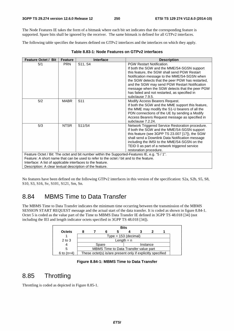
ETSI
ETSI TS 129 274 V12.6.0 (2014-10)2503GPP TS 29.274 version 12.6.0 Release 12
The Node Features IE takes the form of a bitmask where each bit set indicates that the corresponding feature is supported. Spare bits shall be ignored by the receiver. The same bitmask is defined for all GTPv2 interfaces.
The following table specifies the features defined on GTPv2 interfaces and the interfaces on which they apply.
Table 8.83-1: Node Features on GTPv2 interfaces
Feature Octet / Bit Feature Interface Description 5/1 PRN S11, S4 PGW Restart Notification.
If both the SGW and the MME/S4-SGSN support this feature, the SGW shall send PGW Restart Notification message to the MME/S4-SGSN when the SGW detects that the peer PGW has restarted, and the SGW may send PGW Restart Notification message when the SGW detects that the peer PGW has failed and not restarted, as specified in subclause 7.9.5.
5/2 MABR S11 Modify Access Bearers Request. If both the SGW and the MME support this feature, the MME may modify the S1-U bearers of all the PDN connections of the UE by sending a Modify Access Bearers Request message as specified in subclause 7.2.24.
5/3 NTSR S11/S4 Network Triggered Service Restoration procedure. If both the SGW and the MME/S4-SGSN support this feature (see 3GPP TS 23.007 [17]), the SGW shall send a Downlink Data Notification message including the IMSI to the MME/S4-SGSN on the TEID 0 as part of a network triggered service restoration procedure.
Feature Octet / Bit: The octet and bit number within the Supported-Features IE, e.g. "5 / 1". Feature: A short name that can be used to refer to the octet / bit and to the feature. Interface: A list of applicable interfaces to the feature. Description: A clear textual description of the feature.
No features have been defined on the following GTPv2 interfaces in this version of the specification: S2a, S2b, S5, S8, S10, S3, S16, Sv, S101, S121, Sm, Sn.
8.84 MBMS Time to Data Transfer The MBMS Time to Data Transfer indicates the minimum time occurring between the transmission of the MBMS SESSION START REQUEST message and the actual start of the data transfer. It is coded as shown in figure 8.84-1. Octet 5 is coded as the value part of the Time to MBMS Data Transfer IE defined in 3GPP TS 48.018 [34] (not including the IEI and length indicator octets specified in 3GPP TS 48.018 [34]).
Bits Octets 8 7 6 5 4 3 2 1 1 Type = 153 (decimal) 2 to 3 Length = n 4 Spare Instance 5 MBMS Time to Data Transfer value part 6 to (n+4) These octet(s) is/are present only if explicitly specified
Figure 8.84-1: MBMS Time to Data Transfer
8.85 Throttling Throttling is coded as depicted in Figure 8.85-1.
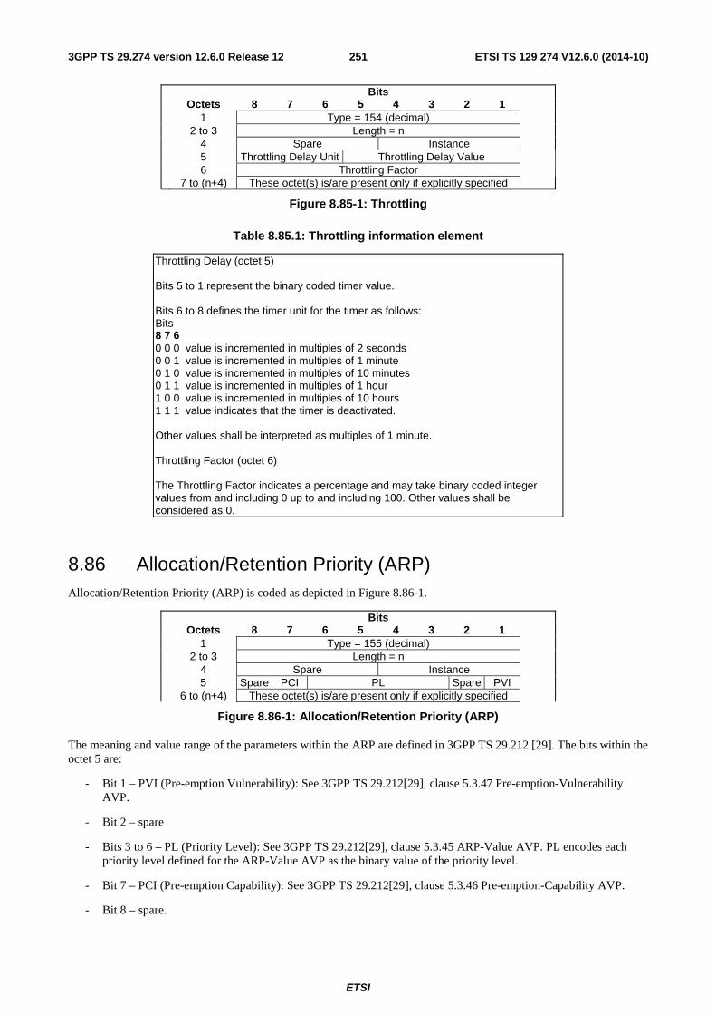
ETSI
ETSI TS 129 274 V12.6.0 (2014-10)2513GPP TS 29.274 version 12.6.0 Release 12
Bits Octets 8 7 6 5 4 3 2 1 1 Type = 154 (decimal) 2 to 3 Length = n 4 Spare Instance 5 Throttling Delay Unit Throttling Delay Value 6 Throttling Factor 7 to (n+4) These octet(s) is/are present only if explicitly specified
Figure 8.85-1: Throttling
Table 8.85.1: Throttling information element
Throttling Delay (octet 5) Bits 5 to 1 represent the binary coded timer value. Bits 6 to 8 defines the timer unit for the timer as follows: Bits 8 7 6 0 0 0 value is incremented in multiples of 2 seconds 0 0 1 value is incremented in multiples of 1 minute 0 1 0 value is incremented in multiples of 10 minutes 0 1 1 value is incremented in multiples of 1 hour 1 0 0 value is incremented in multiples of 10 hours 1 1 1 value indicates that the timer is deactivated. Other values shall be interpreted as multiples of 1 minute. Throttling Factor (octet 6) The Throttling Factor indicates a percentage and may take binary coded integer values from and including 0 up to and including 100. Other values shall be considered as 0.
8.86 Allocation/Retention Priority (ARP) Allocation/Retention Priority (ARP) is coded as depicted in Figure 8.86-1.
Bits Octets 8 7 6 5 4 3 2 1 1 Type = 155 (decimal) 2 to 3 Length = n 4 Spare Instance 5 Spare PCI PL Spare PVI 6 to (n+4) These octet(s) is/are present only if explicitly specified
Figure 8.86-1: Allocation/Retention Priority (ARP)
The meaning and value range of the parameters within the ARP are defined in 3GPP TS 29.212 [29]. The bits within the octet 5 are:
- Bit 1 – PVI (Pre-emption Vulnerability): See 3GPP TS 29.212[29], clause 5.3.47 Pre-emption-Vulnerability AVP.
- Bit 2 – spare
- Bits 3 to 6 – PL (Priority Level): See 3GPP TS 29.212[29], clause 5.3.45 ARP-Value AVP. PL encodes each priority level defined for the ARP-Value AVP as the binary value of the priority level.
- Bit 7 – PCI (Pre-emption Capability): See 3GPP TS 29.212[29], clause 5.3.46 Pre-emption-Capability AVP.
- Bit 8 – spare.
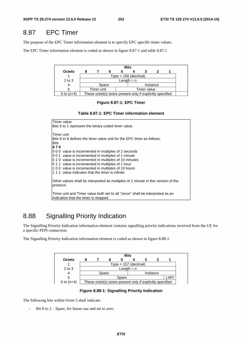
ETSI
ETSI TS 129 274 V12.6.0 (2014-10)2523GPP TS 29.274 version 12.6.0 Release 12
8.87 EPC Timer The purpose of the EPC Timer information element is to specify EPC specific timer values.
The EPC Timer information element is coded as shown in figure 8.87-1 and table 8.87.1
Bits Octets 8 7 6 5 4 3 2 1 1 Type = 156 (decimal) 2 to 3 Length = n 4 Spare Instance 5 Timer unit Timer value 6 to (n+4) These octet(s) is/are present only if explicitly specified
Figure 8.87-1: EPC Timer
Table 8.87.1: EPC Timer information element
Timer value Bits 5 to 1 represent the binary coded timer value. Timer unit Bits 6 to 8 defines the timer value unit for the EPC timer as follows: Bits 8 7 6 0 0 0 value is incremented in multiples of 2 seconds 0 0 1 value is incremented in multiples of 1 minute 0 1 0 value is incremented in multiples of 10 minutes 0 1 1 value is incremented in multiples of 1 hour 1 0 0 value is incremented in multiples of 10 hours 1 1 1 value indicates that the timer is infinite Other values shall be interpreted as multiples of 1 minute in this version of the protocol. Timer unit and Timer value both set to all "zeros" shall be interpreted as an indication that the timer is stopped.
8.88 Signalling Priority Indication The Signalling Priority Indication information element contains signalling priority indications received from the UE for a specific PDN connection.
The Signalling Priority Indication information element is coded as shown in figure 8.88-1.
Bits Octets 8 7 6 5 4 3 2 1 1 Type = 157 (decimal) 2 to 3 Length = n 4 Spare Instance 5 Spare LAPI 6 to (n+4) These octet(s) is/are present only if explicitly specified
Figure 8.88-1: Signalling Priority Indication
The following bits within Octet 5 shall indicate:
- Bit 8 to 2 – Spare, for future use and set to zero.
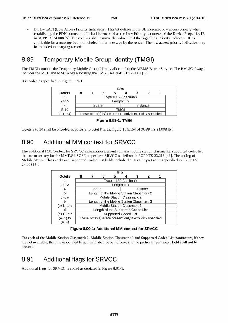
ETSI
ETSI TS 129 274 V12.6.0 (2014-10)2533GPP TS 29.274 version 12.6.0 Release 12
- Bit 1 – LAPI (Low Access Priority Indication): This bit defines if the UE indicated low access priority when establishing the PDN connection. It shall be encoded as the Low Priority parameter of the Device Properties IE in 3GPP TS 24.008 [5]. The receiver shall assume the value "0" if the Signalling Priority Indication IE is applicable for a message but not included in that message by the sender. The low access priority indication may be included in charging records.
8.89 Temporary Mobile Group Identity (TMGI) The TMGI contains the Temporary Mobile Group Identity allocated to the MBMS Bearer Service. The BM-SC always includes the MCC and MNC when allocating the TMGI, see 3GPP TS 29.061 [38].
It is coded as specified in Figure 8.89-1.
Bits Octets 8 7 6 5 4 3 2 1 1 Type = 158 (decimal) 2 to 3 Length = n 4 Spare Instance 5-10 TMGI 11-(n+4) These octet(s) is/are present only if explicitly specified
Figure 8.89-1: TMGI
Octets 5 to 10 shall be encoded as octets 3 to octet 8 in the figure 10.5.154 of 3GPP TS 24.008 [5].
8.90 Additional MM context for SRVCC The additional MM Context for SRVCC information element contains mobile station classmarks, supported codec list that are necessary for the MME/S4-SGSN to perform SRVCC as defined in 3GPP TS 23.216 [43]. The coding of Mobile Station Classmarks and Supported Codec List fields include the IE value part as it is specified in 3GPP TS 24.008 [5].
Bits Octets 8 7 6 5 4 3 2 1 1 Type = 159 (decimal) 2 to 3 Length = n 4 Spare Instance 5 Length of the Mobile Station Classmark 2 6 to a Mobile Station Classmark 2 b Length of the Mobile Station Classmark 3 (b+1) to c Mobile Station Classmark 3 d Length of the Supported Codec List (d+1) to e Supported Codec List (e+1) to
(n+4) These octet(s) is/are present only if explicitly specified
Figure 8.90-1: Additional MM context for SRVCC
For each of the Mobile Station Classmark 2, Mobile Station Classmark 3 and Supported Codec List parameters, if they are not available, then the associated length field shall be set to zero, and the particular parameter field shall not be present.
8.91 Additional flags for SRVCC Additional flags for SRVCC is coded as depicted in Figure 8.91-1.
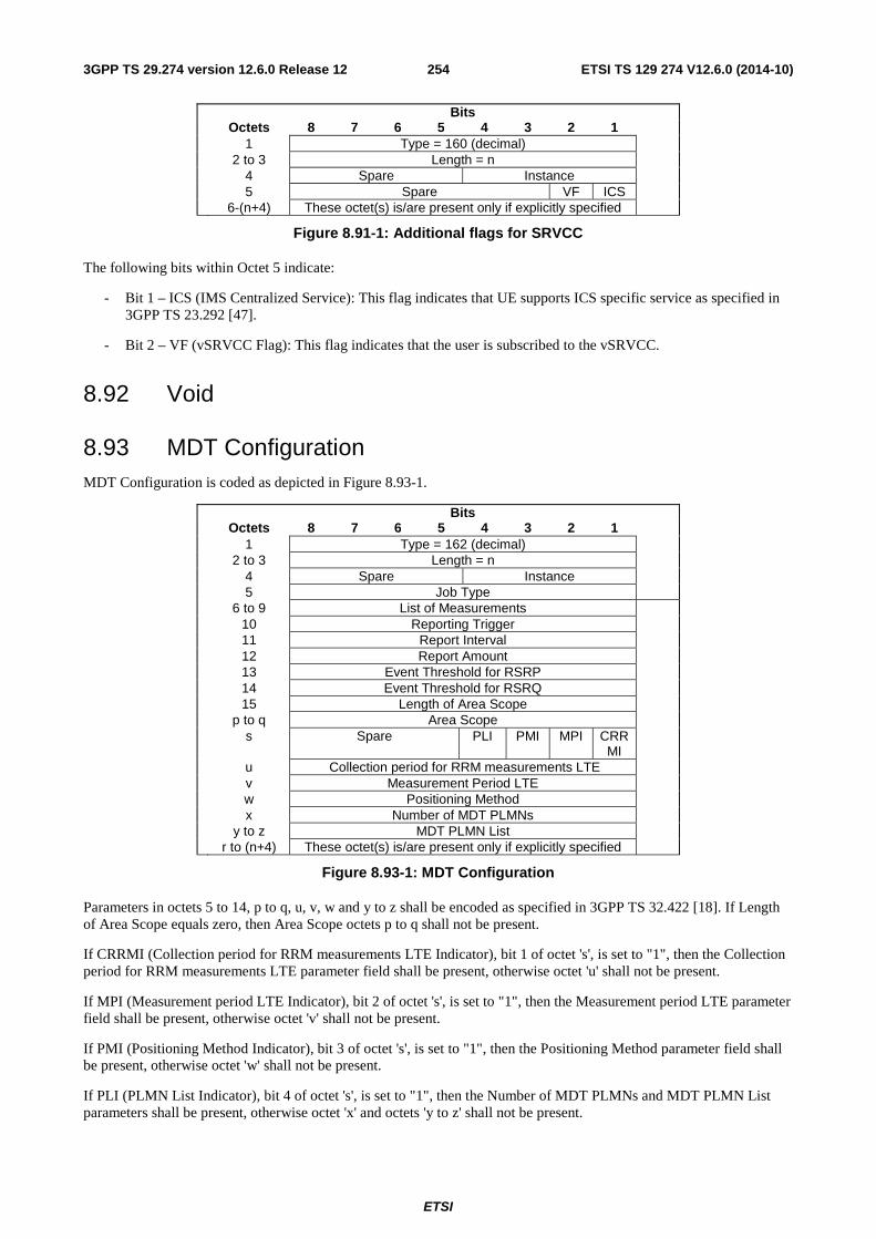
ETSI
ETSI TS 129 274 V12.6.0 (2014-10)2543GPP TS 29.274 version 12.6.0 Release 12
Bits Octets 8 7 6 5 4 3 2 1 1 Type = 160 (decimal) 2 to 3 Length = n 4 Spare Instance 5 Spare VF ICS 6-(n+4) These octet(s) is/are present only if explicitly specified
Figure 8.91-1: Additional flags for SRVCC
The following bits within Octet 5 indicate:
- Bit 1 – ICS (IMS Centralized Service): This flag indicates that UE supports ICS specific service as specified in 3GPP TS 23.292 [47].
- Bit 2 – VF (vSRVCC Flag): This flag indicates that the user is subscribed to the vSRVCC.
8.92 Void
8.93 MDT Configuration MDT Configuration is coded as depicted in Figure 8.93-1.
Bits Octets 8 7 6 5 4 3 2 1 1 Type = 162 (decimal) 2 to 3 Length = n 4 Spare Instance 5 Job Type 6 to 9 List of Measurements 10 Reporting Trigger 11 Report Interval 12 Report Amount 13 Event Threshold for RSRP 14 Event Threshold for RSRQ 15 Length of Area Scope p to q Area Scope s Spare PLI PMI MPI CRR
MI
u Collection period for RRM measurements LTE v Measurement Period LTE w Positioning Method x Number of MDT PLMNs y to z MDT PLMN List r to (n+4) These octet(s) is/are present only if explicitly specified
Figure 8.93-1: MDT Configuration
Parameters in octets 5 to 14, p to q, u, v, w and y to z shall be encoded as specified in 3GPP TS 32.422 [18]. If Length of Area Scope equals zero, then Area Scope octets p to q shall not be present.
If CRRMI (Collection period for RRM measurements LTE Indicator), bit 1 of octet 's', is set to "1", then the Collection period for RRM measurements LTE parameter field shall be present, otherwise octet 'u' shall not be present.
If MPI (Measurement period LTE Indicator), bit 2 of octet 's', is set to "1", then the Measurement period LTE parameter field shall be present, otherwise octet 'v' shall not be present.
If PMI (Positioning Method Indicator), bit 3 of octet 's', is set to "1", then the Positioning Method parameter field shall be present, otherwise octet 'w' shall not be present.
If PLI (PLMN List Indicator), bit 4 of octet 's', is set to "1", then the Number of MDT PLMNs and MDT PLMN List parameters shall be present, otherwise octet 'x' and octets 'y to z' shall not be present.
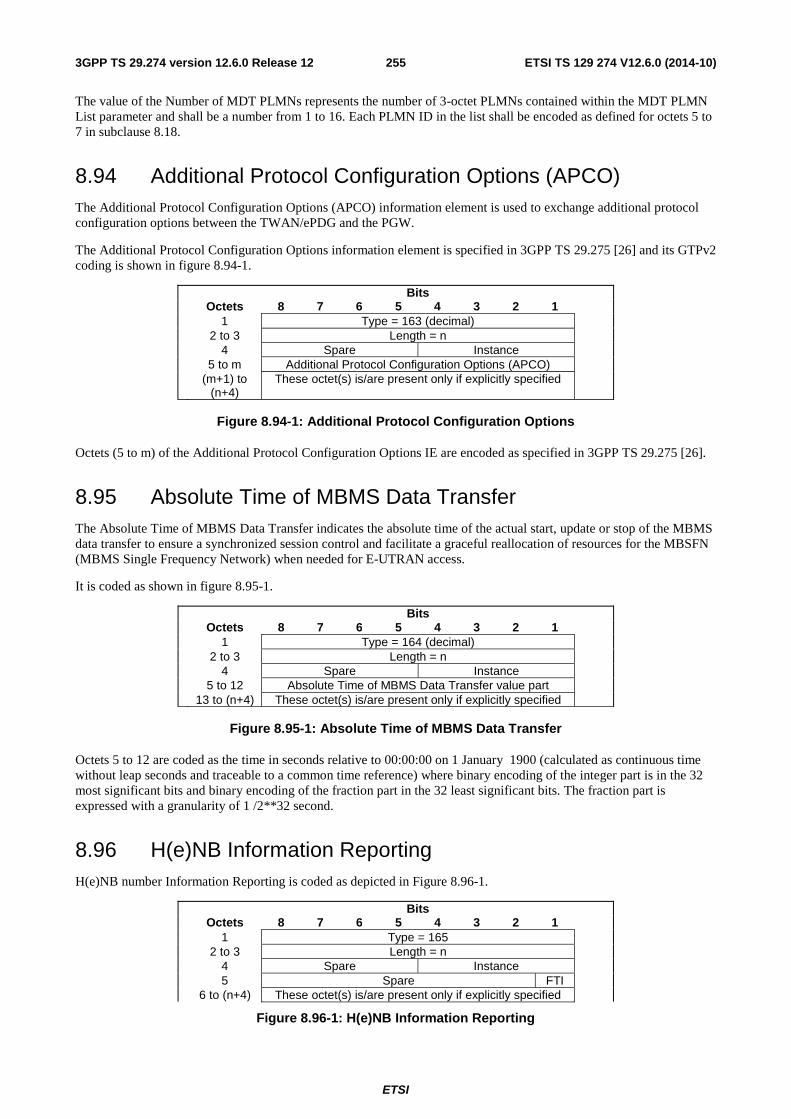
ETSI
ETSI TS 129 274 V12.6.0 (2014-10)2553GPP TS 29.274 version 12.6.0 Release 12
The value of the Number of MDT PLMNs represents the number of 3-octet PLMNs contained within the MDT PLMN List parameter and shall be a number from 1 to 16. Each PLMN ID in the list shall be encoded as defined for octets 5 to 7 in subclause 8.18.
8.94 Additional Protocol Configuration Options (APCO) The Additional Protocol Configuration Options (APCO) information element is used to exchange additional protocol configuration options between the TWAN/ePDG and the PGW.
The Additional Protocol Configuration Options information element is specified in 3GPP TS 29.275 [26] and its GTPv2 coding is shown in figure 8.94-1.
Bits Octets 8 7 6 5 4 3 2 1 1 Type = 163 (decimal) 2 to 3 Length = n 4 Spare Instance 5 to m Additional Protocol Configuration Options (APCO) (m+1) to
(n+4) These octet(s) is/are present only if explicitly specified
Figure 8.94-1: Additional Protocol Configuration Options
Octets (5 to m) of the Additional Protocol Configuration Options IE are encoded as specified in 3GPP TS 29.275 [26].
8.95 Absolute Time of MBMS Data Transfer The Absolute Time of MBMS Data Transfer indicates the absolute time of the actual start, update or stop of the MBMS data transfer to ensure a synchronized session control and facilitate a graceful reallocation of resources for the MBSFN (MBMS Single Frequency Network) when needed for E-UTRAN access.
It is coded as shown in figure 8.95-1.
Bits Octets 8 7 6 5 4 3 2 1 1 Type = 164 (decimal) 2 to 3 Length = n 4 Spare Instance 5 to 12 Absolute Time of MBMS Data Transfer value part 13 to (n+4) These octet(s) is/are present only if explicitly specified
Figure 8.95-1: Absolute Time of MBMS Data Transfer
Octets 5 to 12 are coded as the time in seconds relative to 00:00:00 on 1 January 1900 (calculated as continuous time without leap seconds and traceable to a common time reference) where binary encoding of the integer part is in the 32 most significant bits and binary encoding of the fraction part in the 32 least significant bits. The fraction part is expressed with a granularity of 1 /2**32 second.
8.96 H(e)NB Information Reporting H(e)NB number Information Reporting is coded as depicted in Figure 8.96-1.
Bits Octets 8 7 6 5 4 3 2 1 1 Type = 165 2 to 3 Length = n 4 Spare Instance 5 Spare FTI 6 to (n+4) These octet(s) is/are present only if explicitly specified
Figure 8.96-1: H(e)NB Information Reporting
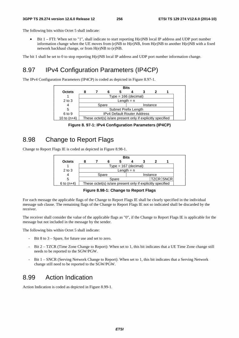
ETSI
ETSI TS 129 274 V12.6.0 (2014-10)2563GPP TS 29.274 version 12.6.0 Release 12
The following bits within Octet 5 shall indicate:
• Bit 1 – FTI: When set to "1", shall indicate to start reporting H(e)NB local IP address and UDP port number information change when the UE moves from (e)NB to H(e)NB, from H(e)NB to another H(e)NB with a fixed network backhaul change, or from H(e)NB to (e)NB.
The bit 1 shall be set to 0 to stop reporting H(e)NB local IP address and UDP port number information change.
8.97 IPv4 Configuration Parameters (IP4CP) The IPv4 Configuration Parameters (IP4CP) is coded as depicted in Figure 8.97-1.
Bits Octets 8 7 6 5 4 3 2 1 1 Type = 166 (decimal) 2 to 3 Length = n 4 Spare Instance 5 Subnet Prefix Length 6 to 9 IPv4 Default Router Address 10 to (n+4) These octet(s) is/are present only if explicitly specified
Figure 8. 97-1: IPv4 Configuration Parameters (IP4CP)
8.98 Change to Report Flags Change to Report Flags IE is coded as depicted in Figure 8.98-1.
Bits Octets 8 7 6 5 4 3 2 1 1 Type = 167 (decimal) 2 to 3 Length = n 4 Spare Instance 5 Spare TZCR SNCR 6 to (n+4) These octet(s) is/are present only if explicitly specified
Figure 8.98-1: Change to Report Flags
For each message the applicable flags of the Change to Report Flags IE shall be clearly specified in the individual message sub clause. The remaining flags of the Change to Report Flags IE not so indicated shall be discarded by the receiver.
The receiver shall consider the value of the applicable flags as "0", if the Change to Report Flags IE is applicable for the message but not included in the message by the sender.
The following bits within Octet 5 shall indicate:
- Bit 8 to 3 – Spare, for future use and set to zero.
- Bit 2 – TZCR (Time Zone Change to Report): When set to 1, this bit indicates that a UE Time Zone change still needs to be reported to the SGW/PGW.
- Bit 1 – SNCR (Serving Network Change to Report): When set to 1, this bit indicates that a Serving Network change still need to be reported to the SGW/PGW.
8.99 Action Indication Action Indication is coded as depicted in Figure 8.99-1.
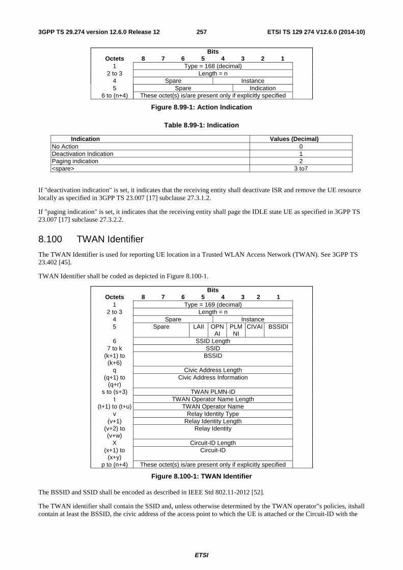
ETSI
ETSI TS 129 274 V12.6.0 (2014-10)2573GPP TS 29.274 version 12.6.0 Release 12
Bits Octets 8 7 6 5 4 3 2 1 1 Type = 168 (decimal) 2 to 3 Length = n 4 Spare Instance 5 Spare Indication 6 to (n+4) These octet(s) is/are present only if explicitly specified
Figure 8.99-1: Action Indication
Table 8.99-1: Indication
Indication Values (Decimal) No Action 0 Deactivation Indication 1 Paging indication 2 <spare> 3 to7
If "deactivation indication" is set, it indicates that the receiving entity shall deactivate ISR and remove the UE resource locally as specified in 3GPP TS 23.007 [17] subclause 27.3.1.2.
If "paging indication" is set, it indicates that the receiving entity shall page the IDLE state UE as specified in 3GPP TS 23.007 [17] subclause 27.3.2.2.
8.100 TWAN Identifier
The TWAN Identifier is used for reporting UE location in a Trusted WLAN Access Network (TWAN). See 3GPP TS 23.402 [45].
TWAN Identifier shall be coded as depicted in Figure 8.100-1.
Bits Octets 8 7 6 5 4 3 2 1 1 Type = 169 (decimal) 2 to 3 Length = n 4 Spare Instance 5 Spare LAII OPN
AI PLMNI
CIVAI BSSIDI
6 SSID Length 7 to k SSID (k+1) to
(k+6) BSSID
q Civic Address Length (q+1) to
(q+r) Civic Address Information
s to (s+3) TWAN PLMN-ID t TWAN Operator Name Length (t+1) to (t+u) TWAN Operator Name v Relay Identity Type (v+1) Relay Identity Length (v+2) to
(v+w) Relay Identity
X Circuit-ID Length (x+1) to
(x+y) Circuit-ID
p to (n+4) These octet(s) is/are present only if explicitly specified
Figure 8.100-1: TWAN Identifier
The BSSID and SSID shall be encoded as described in IEEE Std 802.11-2012 [52].
The TWAN identifier shall contain the SSID and, unless otherwise determined by the TWAN operator"s policies, itshall contain at least the BSSID, the civic address of the access point to which the UE is attached or the Circuit-ID with the
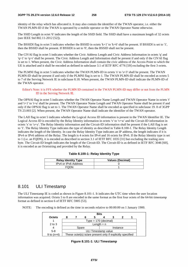
ETSI
ETSI TS 129 274 V12.6.0 (2014-10)2583GPP TS 29.274 version 12.6.0 Release 12
identity of the relay which has allocated it. It may also contain the identifier of the TWAN operator, i.e. either the TWAN PLMN-ID if the TWAN is operated by a mobile operator or the TWAN Operator Name otherwise.
The SSID Length in octet '6' indicates the length of the SSID field. The SSID shall have a maximum length of 32 octets (see IEEE Std 802.11-2012 [52]).
The BSSIDI flag in octet 5 indicates whether the BSSID in octets 'k+1' to 'k+6' shall be present. If BSSIDI is set to '1', then the BSSID shall be present. If BSSIDI is set to '0', then the BSSID shall not be present.
The CIVAI flag in octet 5 indicates whether the Civic Address Length and Civic Address Information in octets 'q' and 'q+1' to 'q+r' shall be present. The Civic Address Length and Information shall be present if and only if the CIVAI flag is set to 1. When present, the Civic Address Information shall contain the civic address of the Access Point to which the UE is attached and it shall be encoded as defined in subclause 3.1 of IETF RFC 4776 [59] excluding the first 3 octets.
The PLMNI flag in octet 5 indicates whether the TWAN PLMN-ID in octets 's' to 's+3' shall be present. The TWAN PLMN-ID shall be present if and only if the PLMNI flag is set to 1. The TWAN PLMN-ID shall be encoded as octets 5 to 7 of the Serving Network IE in subclause 8.18. When present, the TWAN PLMN-ID shall indicate the PLMN-ID of the TWAN operator.
Editor's Note: it is FFS whether the PLMN ID contained in the TWAN PLMN-ID may differ or not from the PLMN ID in the Serving Network IE.
The OPNAI flag in octet 5 indicates whether the TWAN Operator Name Length and TWAN Operator Name in octets 't' and 't+1' to 't+u' shall be present. The TWAN Operator Name Length and TWAN Operator Name shall be present if and only if the OPNAI flag is set to 1. The TWAN Operator Name shall be encoded as specified in subclause 19. 8 of 3GPP TS 23.003 [2]. When present, the TWAN Operator Name shall indicate the identifier of the TWAN operator.
The LAII flag in octet 5 indicates whether the Logical Access ID information is present in the TWAN Identifier IE. The Logical Access ID is encoded by the Relay Identity information in octets 'v' to 'v+w' and the Circuit-ID information in octets 'x' to 'x+y'. The Relay Identity information and the Circuit-ID information shall be present if the LAII flag is set to '1'. The Relay Identity Type indicates the type of identity as described in Table 8.100-1. The Relay Identity Length indicates the length of the Identity. In case the Relay Identity Type indicates an IP address, the length indicates if it is IPv4 or IPv6 address of the Relay. The length is 4 octets for IPv4 and 16 octets for IPv6. If the Relay Identity type is set to 1 (i.e. an FQDN), it is encoded as described in section 3.1 of IETF RFC 1035 [31] but excluding the trailing zero byte. The Circuit-ID length indicates the length of the Circuit-ID. The Circuit-ID is as defined in IETF RFC 3046 [60], it is encoded as an Octetstring and provided by the Relay.
Table 8.100-1: Relay Identity Type
Relay Identity Type Values (Decimal) IPv4 or IPv6 Address 0
FQDN 1
8.101 ULI Timestamp
The ULI Timestamp IE is coded as shown in Figure 8.101-1. It indicates the UTC time when the user location information was acquired. Octets 5 to 8 are encoded in the same format as the first four octets of the 64-bit timestamp format as defined in section 6 of IETF RFC 5905 [53].
NOTE: The encoding is defined as the time in seconds relative to 00:00:00 on 1 January 1900.
Bits Octets 8 7 6 5 4 3 2 1 1 Type = 170 (decimal) 2 to 3 Length = n 4 Spare Instance 5-8 ULI Timestamp value 9 to (n+4) These octet(s) is/are present only if explicitly specified
Figure 8.101-1: ULI Timestamp
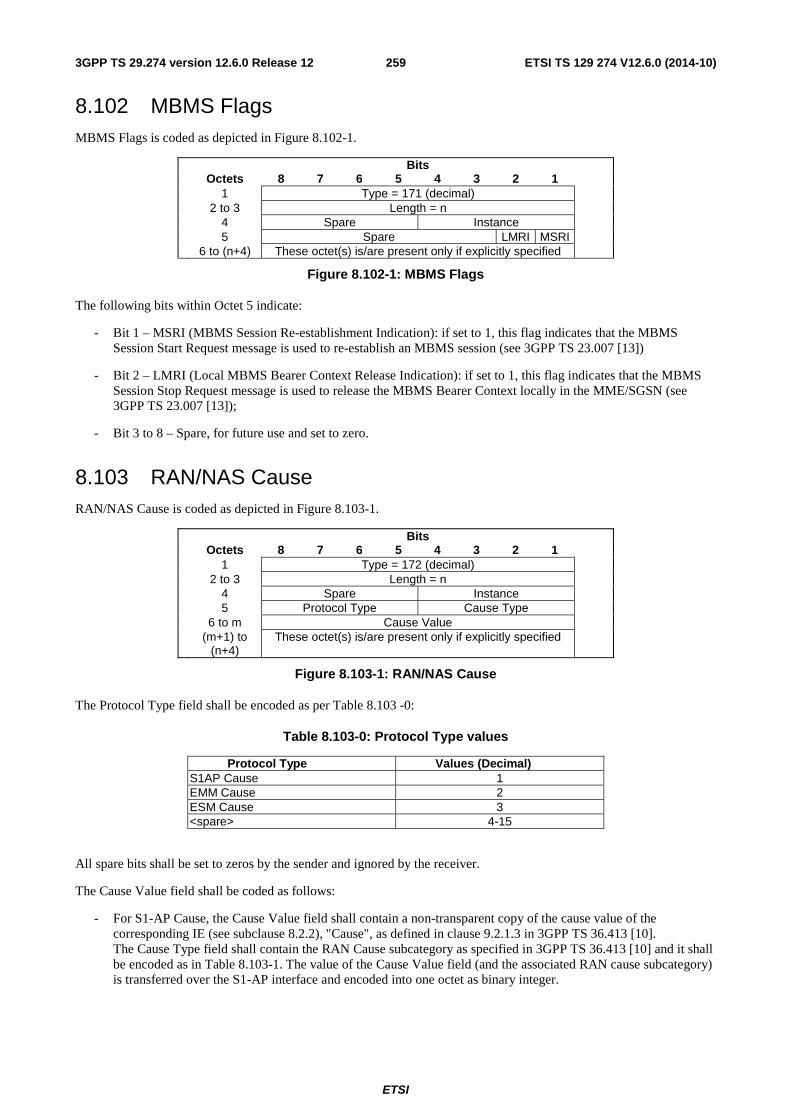
ETSI
ETSI TS 129 274 V12.6.0 (2014-10)2593GPP TS 29.274 version 12.6.0 Release 12
8.102 MBMS Flags MBMS Flags is coded as depicted in Figure 8.102-1.
Bits Octets 8 7 6 5 4 3 2 1 1 Type = 171 (decimal) 2 to 3 Length = n 4 Spare Instance 5 Spare LMRI MSRI 6 to (n+4) These octet(s) is/are present only if explicitly specified
Figure 8.102-1: MBMS Flags
The following bits within Octet 5 indicate:
- Bit 1 – MSRI (MBMS Session Re-establishment Indication): if set to 1, this flag indicates that the MBMS Session Start Request message is used to re-establish an MBMS session (see 3GPP TS 23.007 [13])
- Bit 2 – LMRI (Local MBMS Bearer Context Release Indication): if set to 1, this flag indicates that the MBMS Session Stop Request message is used to release the MBMS Bearer Context locally in the MME/SGSN (see 3GPP TS 23.007 [13]);
- Bit 3 to 8 – Spare, for future use and set to zero.
8.103 RAN/NAS Cause RAN/NAS Cause is coded as depicted in Figure 8.103-1.
Bits Octets 8 7 6 5 4 3 2 1 1 Type = 172 (decimal) 2 to 3 Length = n 4 Spare Instance 5 Protocol Type Cause Type 6 to m Cause Value (m+1) to
(n+4) These octet(s) is/are present only if explicitly specified
Figure 8.103-1: RAN/NAS Cause
The Protocol Type field shall be encoded as per Table 8.103 -0:
Table 8.103-0: Protocol Type values
Protocol Type Values (Decimal) S1AP Cause 1 EMM Cause 2 ESM Cause 3 <spare> 4-15
All spare bits shall be set to zeros by the sender and ignored by the receiver.
The Cause Value field shall be coded as follows:
- For S1-AP Cause, the Cause Value field shall contain a non-transparent copy of the cause value of the corresponding IE (see subclause 8.2.2), "Cause", as defined in clause 9.2.1.3 in 3GPP TS 36.413 [10]. The Cause Type field shall contain the RAN Cause subcategory as specified in 3GPP TS 36.413 [10] and it shall be encoded as in Table 8.103-1. The value of the Cause Value field (and the associated RAN cause subcategory) is transferred over the S1-AP interface and encoded into one octet as binary integer.
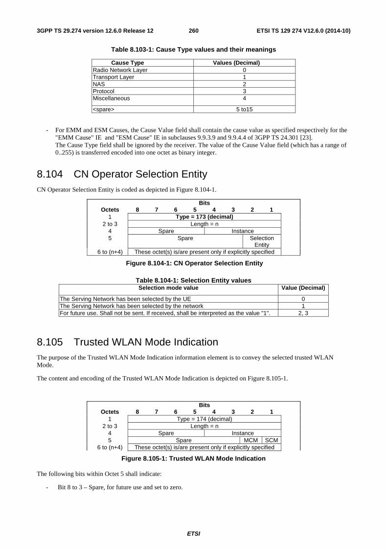
ETSI
ETSI TS 129 274 V12.6.0 (2014-10)2603GPP TS 29.274 version 12.6.0 Release 12
Table 8.103-1: Cause Type values and their meanings
Cause Type Values (Decimal) Radio Network Layer 0 Transport Layer 1 NAS 2 Protocol 3 Miscellaneous 4
<spare> 5 to15
- For EMM and ESM Causes, the Cause Value field shall contain the cause value as specified respectively for the "EMM Cause" IE and "ESM Cause" IE in subclauses 9.9.3.9 and 9.9.4.4 of 3GPP TS 24.301 [23]. The Cause Type field shall be ignored by the receiver. The value of the Cause Value field (which has a range of 0..255) is transferred encoded into one octet as binary integer.
8.104 CN Operator Selection Entity CN Operator Selection Entity is coded as depicted in Figure 8.104-1.
Bits Octets 8 7 6 5 4 3 2 1 1 Type = 173 (decimal) 2 to 3 Length = n 4 Spare Instance 5 Spare Selection
Entity
6 to (n+4) These octet(s) is/are present only if explicitly specified
Figure 8.104-1: CN Operator Selection Entity
Table 8.104-1: Selection Entity valuesSelection mode value Value (Decimal)
The Serving Network has been selected by the UE 0 The Serving Network has been selected by the network 1 For future use. Shall not be sent. If received, shall be interpreted as the value "1". 2, 3
8.105 Trusted WLAN Mode Indication The purpose of the Trusted WLAN Mode Indication information element is to convey the selected trusted WLAN Mode.
The content and encoding of the Trusted WLAN Mode Indication is depicted on Figure 8.105-1.
Bits Octets 8 7 6 5 4 3 2 1 1 Type = 174 (decimal) 2 to 3 Length = n 4 Spare Instance 5 Spare MCM SCM 6 to (n+4) These octet(s) is/are present only if explicitly specified
Figure 8.105-1: Trusted WLAN Mode Indication
The following bits within Octet 5 shall indicate:
- Bit 8 to 3 – Spare, for future use and set to zero.
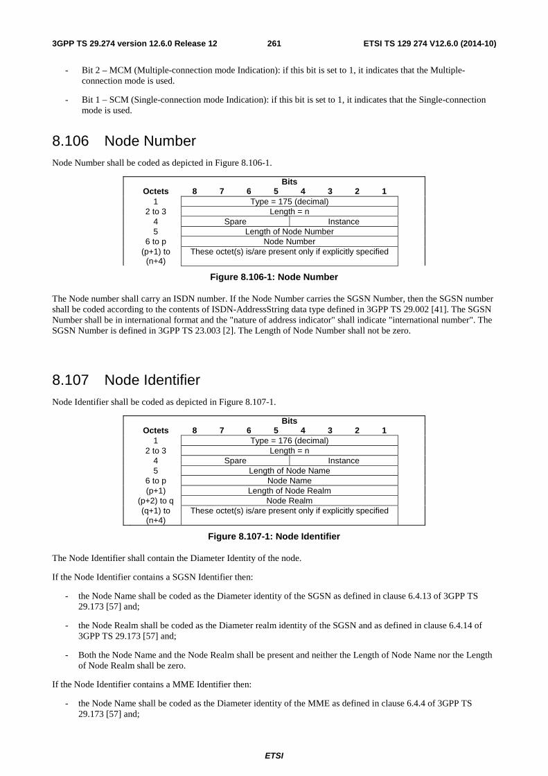
ETSI
ETSI TS 129 274 V12.6.0 (2014-10)2613GPP TS 29.274 version 12.6.0 Release 12
- Bit 2 – MCM (Multiple-connection mode Indication): if this bit is set to 1, it indicates that the Multiple-connection mode is used.
- Bit 1 – SCM (Single-connection mode Indication): if this bit is set to 1, it indicates that the Single-connection mode is used.
8.106 Node Number Node Number shall be coded as depicted in Figure 8.106-1.
Bits Octets 8 7 6 5 4 3 2 1 1 Type = 175 (decimal) 2 to 3 Length = n 4 Spare Instance 5 Length of Node Number 6 to p Node Number (p+1) to
(n+4) These octet(s) is/are present only if explicitly specified
Figure 8.106-1: Node Number
The Node number shall carry an ISDN number. If the Node Number carries the SGSN Number, then the SGSN number shall be coded according to the contents of ISDN-AddressString data type defined in 3GPP TS 29.002 [41]. The SGSN Number shall be in international format and the "nature of address indicator" shall indicate "international number". The SGSN Number is defined in 3GPP TS 23.003 [2]. The Length of Node Number shall not be zero.
8.107 Node Identifier Node Identifier shall be coded as depicted in Figure 8.107-1.
Bits Octets 8 7 6 5 4 3 2 1 1 Type = 176 (decimal) 2 to 3 Length = n 4 Spare Instance 5 Length of Node Name 6 to p Node Name (p+1) Length of Node Realm (p+2) to q Node Realm (q+1) to
(n+4) These octet(s) is/are present only if explicitly specified
Figure 8.107-1: Node Identifier
The Node Identifier shall contain the Diameter Identity of the node.
If the Node Identifier contains a SGSN Identifier then:
- the Node Name shall be coded as the Diameter identity of the SGSN as defined in clause 6.4.13 of 3GPP TS 29.173 [57] and;
- the Node Realm shall be coded as the Diameter realm identity of the SGSN and as defined in clause 6.4.14 of 3GPP TS 29.173 [57] and;
- Both the Node Name and the Node Realm shall be present and neither the Length of Node Name nor the Length of Node Realm shall be zero.
If the Node Identifier contains a MME Identifier then:
- the Node Name shall be coded as the Diameter identity of the MME as defined in clause 6.4.4 of 3GPP TS 29.173 [57] and;
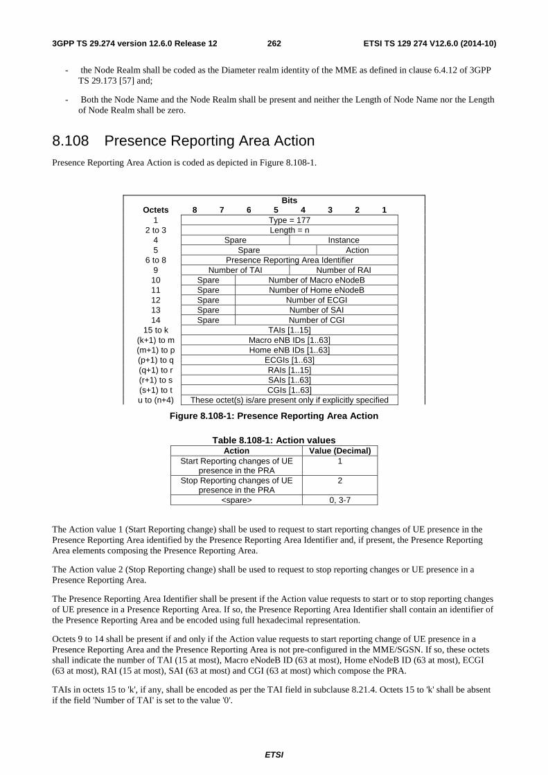
ETSI
ETSI TS 129 274 V12.6.0 (2014-10)2623GPP TS 29.274 version 12.6.0 Release 12
- the Node Realm shall be coded as the Diameter realm identity of the MME as defined in clause 6.4.12 of 3GPP TS 29.173 [57] and;
- Both the Node Name and the Node Realm shall be present and neither the Length of Node Name nor the Length of Node Realm shall be zero.
8.108 Presence Reporting Area Action Presence Reporting Area Action is coded as depicted in Figure 8.108-1.
Bits Octets 8 7 6 5 4 3 2 1 1 Type = 177 2 to 3 Length = n 4 Spare Instance 5 Spare Action 6 to 8 Presence Reporting Area Identifier 9 Number of TAI Number of RAI 10 Spare Number of Macro eNodeB 11 Spare Number of Home eNodeB 12 Spare Number of ECGI 13 Spare Number of SAI 14 Spare Number of CGI 15 to k TAIs [1..15] (k+1) to m Macro eNB IDs [1..63] (m+1) to p Home eNB IDs [1..63] (p+1) to q ECGIs [1..63] (q+1) to r RAIs [1..15] (r+1) to s SAIs [1..63] (s+1) to t CGIs [1..63] u to (n+4) These octet(s) is/are present only if explicitly specified
Figure 8.108-1: Presence Reporting Area Action
Table 8.108-1: Action valuesAction Value (Decimal)
Start Reporting changes of UE presence in the PRA
1
Stop Reporting changes of UE presence in the PRA
2
<spare> 0, 3-7
The Action value 1 (Start Reporting change) shall be used to request to start reporting changes of UE presence in the Presence Reporting Area identified by the Presence Reporting Area Identifier and, if present, the Presence Reporting Area elements composing the Presence Reporting Area.
The Action value 2 (Stop Reporting change) shall be used to request to stop reporting changes or UE presence in a Presence Reporting Area.
The Presence Reporting Area Identifier shall be present if the Action value requests to start or to stop reporting changes of UE presence in a Presence Reporting Area. If so, the Presence Reporting Area Identifier shall contain an identifier of the Presence Reporting Area and be encoded using full hexadecimal representation.
Octets 9 to 14 shall be present if and only if the Action value requests to start reporting change of UE presence in a Presence Reporting Area and the Presence Reporting Area is not pre-configured in the MME/SGSN. If so, these octets shall indicate the number of TAI (15 at most), Macro eNodeB ID (63 at most), Home eNodeB ID (63 at most), ECGI (63 at most), RAI (15 at most), SAI (63 at most) and CGI (63 at most) which compose the PRA.
TAIs in octets 15 to 'k', if any, shall be encoded as per the TAI field in subclause 8.21.4. Octets 15 to 'k' shall be absent if the field 'Number of TAI' is set to the value '0'.
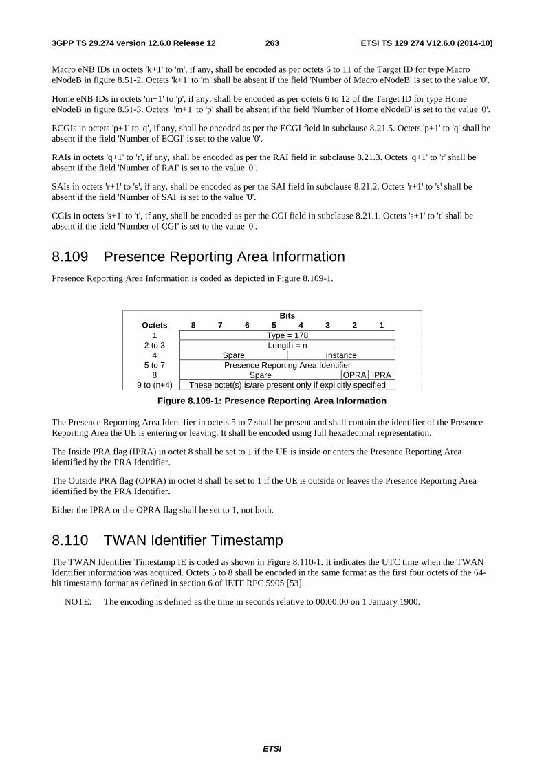
ETSI
ETSI TS 129 274 V12.6.0 (2014-10)2633GPP TS 29.274 version 12.6.0 Release 12
Macro eNB IDs in octets 'k+1' to 'm', if any, shall be encoded as per octets 6 to 11 of the Target ID for type Macro eNodeB in figure 8.51-2. Octets 'k+1' to 'm' shall be absent if the field 'Number of Macro eNodeB' is set to the value '0'.
Home eNB IDs in octets 'm+1' to 'p', if any, shall be encoded as per octets 6 to 12 of the Target ID for type Home eNodeB in figure 8.51-3. Octets 'm+1' to 'p' shall be absent if the field 'Number of Home eNodeB' is set to the value '0'.
ECGIs in octets 'p+1' to 'q', if any, shall be encoded as per the ECGI field in subclause 8.21.5. Octets 'p+1' to 'q' shall be absent if the field 'Number of ECGI' is set to the value '0'.
RAIs in octets 'q+1' to 'r', if any, shall be encoded as per the RAI field in subclause 8.21.3. Octets 'q+1' to 'r' shall be absent if the field 'Number of RAI' is set to the value '0'.
SAIs in octets 'r+1' to 's', if any, shall be encoded as per the SAI field in subclause 8.21.2. Octets 'r+1' to 's' shall be absent if the field 'Number of SAI' is set to the value '0'.
CGIs in octets 's+1' to 't', if any, shall be encoded as per the CGI field in subclause 8.21.1. Octets 's+1' to 't' shall be absent if the field 'Number of CGI' is set to the value '0'.
8.109 Presence Reporting Area Information Presence Reporting Area Information is coded as depicted in Figure 8.109-1.
Bits Octets 8 7 6 5 4 3 2 1 1 Type = 178 2 to 3 Length = n 4 Spare Instance 5 to 7 Presence Reporting Area Identifier 8 Spare OPRA IPRA 9 to (n+4) These octet(s) is/are present only if explicitly specified
Figure 8.109-1: Presence Reporting Area Information
The Presence Reporting Area Identifier in octets 5 to 7 shall be present and shall contain the identifier of the Presence Reporting Area the UE is entering or leaving. It shall be encoded using full hexadecimal representation.
The Inside PRA flag (IPRA) in octet 8 shall be set to 1 if the UE is inside or enters the Presence Reporting Area identified by the PRA Identifier.
The Outside PRA flag (OPRA) in octet 8 shall be set to 1 if the UE is outside or leaves the Presence Reporting Area identified by the PRA Identifier.
Either the IPRA or the OPRA flag shall be set to 1, not both.
8.110 TWAN Identifier Timestamp The TWAN Identifier Timestamp IE is coded as shown in Figure 8.110-1. It indicates the UTC time when the TWAN Identifier information was acquired. Octets 5 to 8 shall be encoded in the same format as the first four octets of the 64-bit timestamp format as defined in section 6 of IETF RFC 5905 [53].
NOTE: The encoding is defined as the time in seconds relative to 00:00:00 on 1 January 1900.
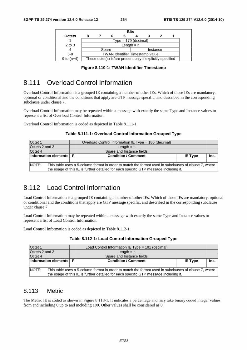
ETSI
ETSI TS 129 274 V12.6.0 (2014-10)2643GPP TS 29.274 version 12.6.0 Release 12
Bits Octets 8 7 6 5 4 3 2 1 1 Type = 179 (decimal) 2 to 3 Length = n 4 Spare Instance 5-8 TWAN Identifier Timestamp value 9 to (n+4) These octet(s) is/are present only if explicitly specified
Figure 8.110-1: TWAN Identifier Timestamp
8.111 Overload Control Information Overload Control Information is a grouped IE containing a number of other IEs. Which of those IEs are mandatory, optional or conditional and the conditions that apply are GTP message specific, and described in the corresponding subclause under clause 7.
Overload Control Information may be repeated within a message with exactly the same Type and Instance values to represent a list of Overload Control Information.
Overload Control Information is coded as depicted in Table 8.111-1.
Table 8.111-1: Overload Control Information Grouped Type
Octet 1 Overload Control Information IE Type = 180 (decimal) Octets 2 and 3 Length = n Octet 4 Spare and Instance fields Information elements P Condition / Comment IE Type Ins.
NOTE: This table uses a 5-column format in order to match the format used in subclauses of clause 7, where
the usage of this IE is further detailed for each specific GTP message including it.
8.112 Load Control Information Load Control Information is a grouped IE containing a number of other IEs. Which of those IEs are mandatory, optional or conditional and the conditions that apply are GTP message specific, and described in the corresponding subclause under clause 7.
Load Control Information may be repeated within a message with exactly the same Type and Instance values to represent a list of Load Control Information.
Load Control Information is coded as depicted in Table 8.112-1.
Table 8.112-1: Load Control Information Grouped Type
Octet 1 Load Control Information IE Type = 181 (decimal) Octets 2 and 3 Length = n Octet 4 Spare and Instance fields Information elements P Condition / Comment IE Type Ins.
NOTE: This table uses a 5-column format in order to match the format used in subclauses of clause 7, where
the usage of this IE is further detailed for each specific GTP message including it.
8.113 Metric
The Metric IE is coded as shown in Figure 8.113-1. It indicates a percentage and may take binary coded integer values from and including 0 up to and including 100. Other values shall be considered as 0.
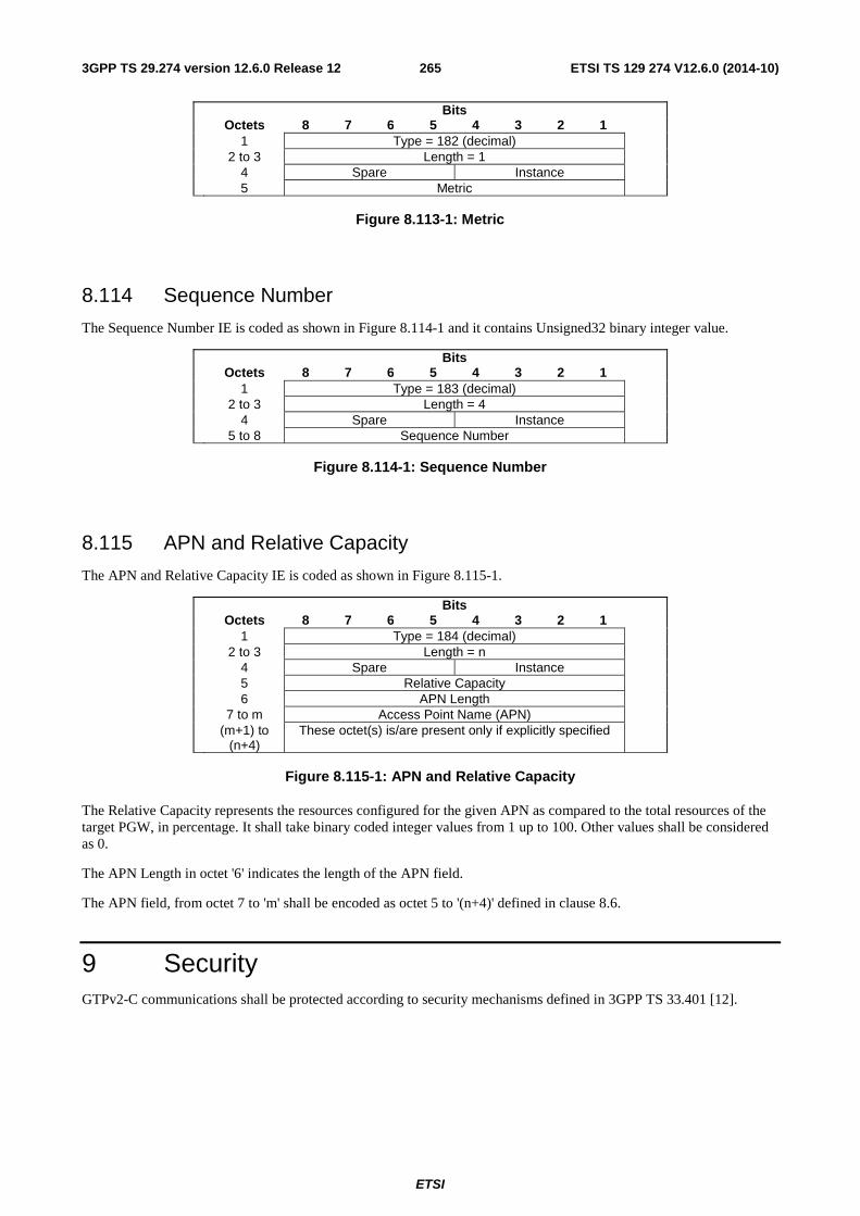
ETSI
ETSI TS 129 274 V12.6.0 (2014-10)2653GPP TS 29.274 version 12.6.0 Release 12
Bits Octets 8 7 6 5 4 3 2 1 1 Type = 182 (decimal) 2 to 3 Length = 1 4 Spare Instance 5 Metric
Figure 8.113-1: Metric
8.114 Sequence Number
The Sequence Number IE is coded as shown in Figure 8.114-1 and it contains Unsigned32 binary integer value.
Bits Octets 8 7 6 5 4 3 2 1 1 Type = 183 (decimal) 2 to 3 Length = 4 4 Spare Instance 5 to 8 Sequence Number
Figure 8.114-1: Sequence Number
8.115 APN and Relative Capacity
The APN and Relative Capacity IE is coded as shown in Figure 8.115-1.
Bits Octets 8 7 6 5 4 3 2 1 1 Type = 184 (decimal) 2 to 3 Length = n 4 Spare Instance 5 Relative Capacity 6 APN Length 7 to m Access Point Name (APN) (m+1) to
(n+4) These octet(s) is/are present only if explicitly specified
Figure 8.115-1: APN and Relative Capacity
The Relative Capacity represents the resources configured for the given APN as compared to the total resources of the target PGW, in percentage. It shall take binary coded integer values from 1 up to 100. Other values shall be considered as 0.
The APN Length in octet '6' indicates the length of the APN field.
The APN field, from octet 7 to 'm' shall be encoded as octet 5 to '(n+4)' defined in clause 8.6.
9 Security GTPv2-C communications shall be protected according to security mechanisms defined in 3GPP TS 33.401 [12].
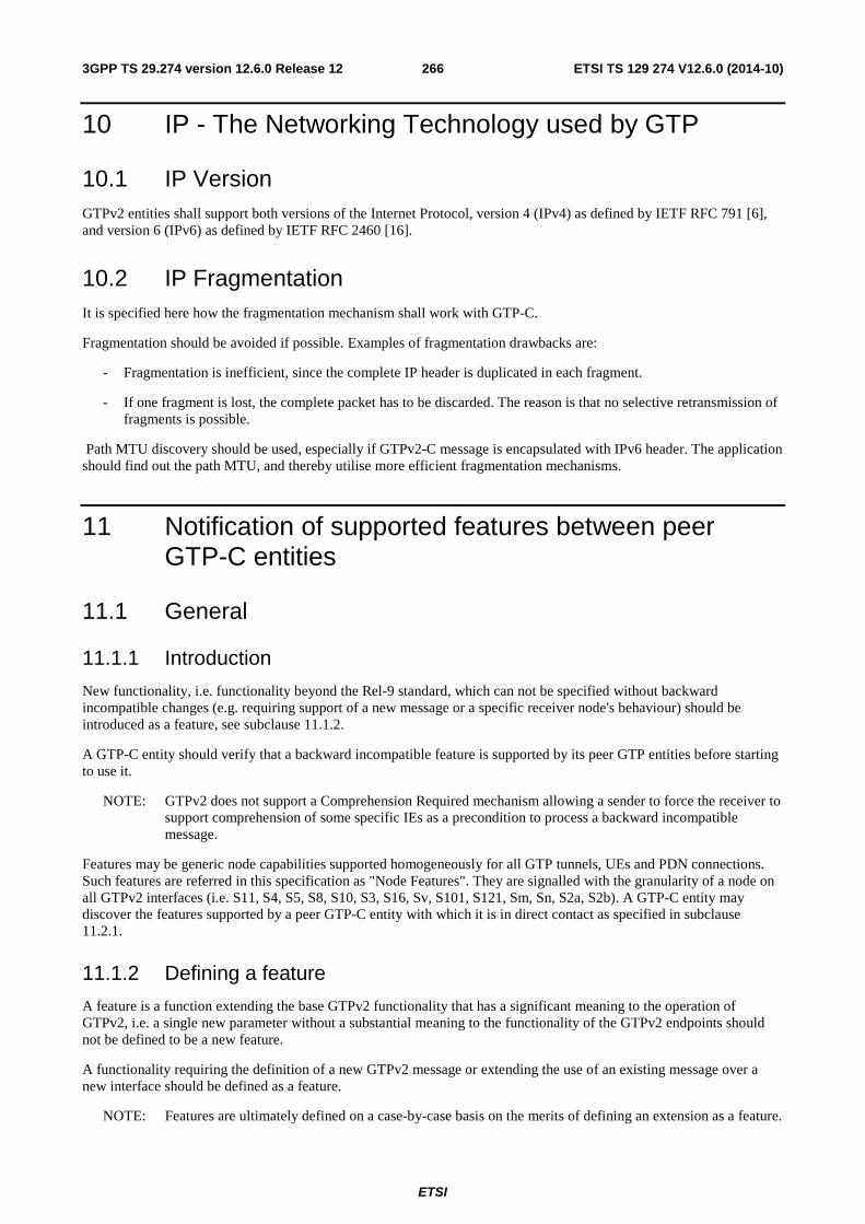
ETSI
ETSI TS 129 274 V12.6.0 (2014-10)2663GPP TS 29.274 version 12.6.0 Release 12
10 IP - The Networking Technology used by GTP
10.1 IP Version GTPv2 entities shall support both versions of the Internet Protocol, version 4 (IPv4) as defined by IETF RFC 791 [6], and version 6 (IPv6) as defined by IETF RFC 2460 [16].
10.2 IP Fragmentation It is specified here how the fragmentation mechanism shall work with GTP-C.
Fragmentation should be avoided if possible. Examples of fragmentation drawbacks are:
- Fragmentation is inefficient, since the complete IP header is duplicated in each fragment.
- If one fragment is lost, the complete packet has to be discarded. The reason is that no selective retransmission of fragments is possible.
Path MTU discovery should be used, especially if GTPv2-C message is encapsulated with IPv6 header. The application should find out the path MTU, and thereby utilise more efficient fragmentation mechanisms.
11 Notification of supported features between peer GTP-C entities
11.1 General
11.1.1 Introduction
New functionality, i.e. functionality beyond the Rel-9 standard, which can not be specified without backward incompatible changes (e.g. requiring support of a new message or a specific receiver node's behaviour) should be introduced as a feature, see subclause 11.1.2.
A GTP-C entity should verify that a backward incompatible feature is supported by its peer GTP entities before starting to use it.
NOTE: GTPv2 does not support a Comprehension Required mechanism allowing a sender to force the receiver to support comprehension of some specific IEs as a precondition to process a backward incompatible message.
Features may be generic node capabilities supported homogeneously for all GTP tunnels, UEs and PDN connections. Such features are referred in this specification as "Node Features". They are signalled with the granularity of a node on all GTPv2 interfaces (i.e. S11, S4, S5, S8, S10, S3, S16, Sv, S101, S121, Sm, Sn, S2a, S2b). A GTP-C entity may discover the features supported by a peer GTP-C entity with which it is in direct contact as specified in subclause 11.2.1.
11.1.2 Defining a feature
A feature is a function extending the base GTPv2 functionality that has a significant meaning to the operation of GTPv2, i.e. a single new parameter without a substantial meaning to the functionality of the GTPv2 endpoints should not be defined to be a new feature.
A functionality requiring the definition of a new GTPv2 message or extending the use of an existing message over a new interface should be defined as a feature.
NOTE: Features are ultimately defined on a case-by-case basis on the merits of defining an extension as a feature.
ETSI
ETSI TS 129 274 V12.6.0 (2014-10)2673GPP TS 29.274 version 12.6.0 Release 12
Features should be defined so that they are independent from each other. A GTP-C entity may support the same feature over different interfaces, e.g. an SGW may support a feature over both S11 and S4 interface, however support of a feature on a given interface shall not depend on the support of the same or another feature on another interface.
11.2 Dynamic discovery of supported features
11.2.1 General
A node supporting at least one feature defined in the Node Features IE shall support dynamic discovery of supported features as specified in the following subclauses.
11.2.2 Features supported by direct peer GTP-C entities
A node shall signal to a direct peer node the list of features it supports by sending the Sending Node Features IE in the Echo Request and Echo Response messages.
An exception to this is where the sending node does not support or use any features towards the peer node and is not prepared to accept a message which is constructed by making use of any features.
The peer receiving the Sending Node Features IE shall store the list of features supported by the sending node per IP address and only update this list based on the Sending Node Features IE in the Echo Request and Echo Response messages, and it shall only use common supported features to initiate subsequent GTPv2 messages towards this IP address.
12 GTP-C load & overload control mechanism
12.1 General
12.1.1 GTP-C overload problem
GTP-C entities can communicate with other GTP-C peers in direct contact (e.g. MME and SGW) or remote GTP-C peers through intermediate GTP-C entities (e.g. MME and PGW via the SGW). In normal conditions, requests sent by a GTP-C entity can be processed by the receiving GTP-C entity which can send back a message indicating the result of the request (success/failure).
Overload situations in a GTP-C entity occur when the number of incoming requests exceeds the maximum request throughput supported by the receiving GTP-C entity, e.g. when the internal available resources of the GTP-C entity, such as processing power or memory, are not sufficient to serve the number of incoming requests. As a consequence of the overload situation, the receiving GTP-C entity cannot successfully process the exceeding proportion of requests. These requests can be either simply dropped or extremely delayed in the processing. At best, the GTP-C entity may have enough internal resources to send back to the request initiator a message indicating that the requests cannot be successfully processed. Whatever the behaviour of the overloaded GTP-C entities, the rate of successfully processed requests and consequently the overall performances of the network decrease.
NOTE: GTP-C overload control does not target to address transport network congestion. It assumes a transport network that is still capable to exchange signalling traffic.
Given the nature of GTP-C protocol in how it relies on retransmissions of unacknowledged requests (GTP-C is carried over UDP transport), when a GTP-C entity experiences overload (or severe overload) the number of unacknowledged GTP-C messages compounds exponentially and can lead to a node congestion or even collapse. An overload or failure of a node can lead to an increase of the load on the other nodes in the network and, in the worst case, turn into a complete network issue via a snowball effect.
The impact of GTP-C overload to services can be such as:
- loss of PDN connectivity (IMS, Internet …) and associated services;
ETSI
ETSI TS 129 274 V12.6.0 (2014-10)2683GPP TS 29.274 version 12.6.0 Release 12
- loss of ability to setup and release radio and core network bearers necessary to support services e.g. GBR bearers for VoLTE;
- loss of ability to report to the PGW/PCRF user's information changes, e.g. location information for emergency services and lawful intercept, changes in RAT or QoS;
- and billing errors and a loss of revenue.
12.1.2 Scenarios leading to overload
Reasons for these temporary overload cases can be many and various in an operational network, such as insufficient internal resource capacity of a GTP-C entity faced with a sudden burst of requests, e.g. after network failure/restart procedures affecting a large number of users, deficiency of a GTP-C entity component leading to a drastic reduction of the overall performances of the GTP-C entity.
Examples of GTP-C signalling based scenarios which can cause GTP-C overload are:
- a traffic flood resulting from the failure of a network element, inducing a signalling spike, e.g. when the network needs to re-establish the PDN connections affected by the failure of an EPC node;
- a traffic flood resulting from a large number of users performing TAU/RAU or from frequent transitions between idle and connected mode;
- an exceptional event locally generating a traffic spike, e.g. a large amount of calls (and dedicated bearers) being setup almost simultaneously upon a catastrophic event or an exceptional but predictable event (e.g. Christmas, New year);
- Frequent RAT-reselection due to scattered non-3GPP (e.g. WiFi) coverage or massive mobility between 3GPP and non-3GPP coverage may potentially cause frequent or massive intersystem change activities, i.e. UEs trying to either create PDN connections over the new access or moving PDN connections between 3GPP and non-3GPP coverage.
Besides, GTP-C load balancing based only on semi-static DNS weights can lead to a load imbalance and thus GTP-C signalling scenarios, such as those mentioned above, may result in an overload of the SGWs or PGWs with the highest load while there is still remaining capacity on other SGWs or PGWs.
12.1.3 Load & overload control concepts
Load control refers to "GTP-C signalling based Load Control" as defined in subclause 4.3.7.1a.1 of 3GPP TS 23.401 [3] and subclause 5.3.6.1a of 3GPP TS 23.060 [35].
Overload control refers to "GTP-C signaling based Overload Control" as defined in subclause 4.3.7.1a.2 of 3GPP TS 23.401 [3] and subclause 5.3.6.1a of 3GPP TS 23.060 [35].
Load control and overload control are two distinct but complementary concepts:
- load control enables a GTP-C entity (e.g. an SGW/PGW) to send its load information to a GTP-C peer (e.g. an MME/SGSN, ePDG, TWAN) to adaptively balance the session load across entities supporting the same function (e.g. an SGW cluster) according to their effective load. The load information reflects the operating status of the resources of the GTP-C entity.
- overload control enables a GTP-C entity becoming or being overloaded to gracefully reduce its incoming signalling load by instructing its GTP-C peers to reduce sending traffic according to its available signalling capacity to successfully process the traffic. A GTP-C entity is in overload when it operates over its signalling capacity which results in diminished performance (including impacts to handling of incoming and outgoing traffic).
Load control allows for better balancing of the session load, so as to attempt to prevent overload in the first place (preventive action). Overload control aims at shedding the incoming traffic as close to the traffic source as possible generally when an overload has occurred (reactive action), so to avoid spreading the problem inside the network and to avoid using resources of intermediate nodes in the network for signalling that would anyhow be discarded by the overloaded node.
Load control does not trigger overload mitigation actions even if the GTP-C entity reports a high load.
ETSI
ETSI TS 129 274 V12.6.0 (2014-10)2693GPP TS 29.274 version 12.6.0 Release 12
Load control and overload control may be supported and activated independently in the network.
12.2 Load control solution
12.2.1 Principles of load control
The stage 2 requirements on GTP-C load control solution are defined in clause 4.3.7.1a.1 of 3GPP TS 23.401 [3] and clause 5.3.6.1a of 3GPP TS 23.060 [35]. The high level principles are summarized below:
a) Load Control is an optional feature;
b) a GTP-C node may signal its Load Control Information to reflect the operating status of its resources, allowing the receiving GTP-C peer node to use this information to augment the existing GW selection procedures;
c) the calculation of the Load Control Information is implementation dependent and its calculation and transfer shall not add significant additional load to the node itself and to its corresponding peer nodes;
d) the Load Control Information may provide load information of a GTP-C node (e.g. a PGW) or, if the APN level load control feature is supported, may provide the load information about specific APN(s);
e) the SGW may send its Load Control Information to the MME/S4-SGSN. The PGW may send its Load Control Information to the MME/S4-SGSN via the SGW. For non-3GPP access based interfaces, the PGW may send its Load Control Information to the ePDG and TWAN;
f) the Load Control Information shall be piggybacked in GTP-C request or response messages such that the exchange of Load Control Information does not trigger extra signalling;
NOTE: The inclusion of Load Control Information in existing messages means that the frequency of transmission of load control information increases as the session load increases, allowing for faster feedback and thus better regulation of the load.
g) a node supporting Load Control sends Load Control Information to a peer GTP-C node based on local configuration (see clause 12.2.6);
h) the format of the Load Control Information shall be specified with enough precision to guarantee a common interpretation of this information allowing interoperability between nodes of different vendors;
i) for the inter-PLMN case, local configuration may restrict the exchange and use of Load Control Information across PLMNs;
j) the GTP-C node may decide to send different values of Load Control Information on inter-network (roaming) and on intra-network (non-roaming) interfaces based on local configuration, i.e. the values sent on intra-network interfaces may differ from the values sent on inter-network interfaces. However, on intra-network interfaces, the node should send the same values between the 3GPP and non-3GPP access based interfaces.
k) the Load Control Information received via GTP-C signalling shall be used in conjunction with the information received from the DNS, during the node selection procedure. Refer to 3GPP TS 29.303 [32] for further details.
12.2.2 Applicability to 3GPP and non-3GPP access based interfaces
Load Control may be supported on the 3GPP & non-3GPP access based interfaces and nodes as summarized by the Table 12.2.2-1.
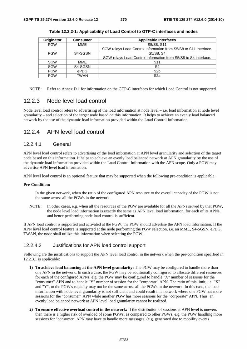
ETSI
ETSI TS 129 274 V12.6.0 (2014-10)2703GPP TS 29.274 version 12.6.0 Release 12
Table 12.2.2-1: Applicability of Load Control to GTP-C interfaces and nodes
Originator Consumer Applicable Interfaces PGW MME S5/S8, S11
SGW relays Load Control Information from S5/S8 to S11 interface. PGW S4-SGSN S5/S8, S4
SGW relays Load Control Information from S5/S8 to S4 interface. SGW MME S11 SGW S4-SGSN S4 PGW ePDG S2b PGW TWAN S2a
NOTE: Refer to Annex D.1 for information on the GTP-C interfaces for which Load Control is not supported.
12.2.3 Node level load control
Node level load control refers to advertising of the load information at node level – i.e. load information at node level granularity – and selection of the target node based on this information. It helps to achieve an evenly load balanced network by the use of the dynamic load information provided within the Load Control Information.
12.2.4 APN level load control
12.2.4.1 General
APN level load control refers to advertising of the load information at APN level granularity and selection of the target node based on this information. It helps to achieve an evenly load balanced network at APN granularity by the use of the dynamic load information provided within the Load Control Information with the APN scope. Only a PGW may advertise APN level load information.
APN level load control is an optional feature that may be supported when the following pre-condition is applicable.
Pre-Condition:
In the given network, when the ratio of the configured APN resource to the overall capacity of the PGW is not the same across all the PGWs in the network.
NOTE: In other cases, e.g. when all the resources of the PGW are available for all the APNs served by that PGW, the node level load information is exactly the same as APN level load information, for each of its APNs, and hence performing node load control is sufficient.
If APN load control is supported and activated at the PGW, the PGW should advertise the APN load information. If the APN level load control feature is supported at the node performing the PGW selection, i.e. an MME, S4-SGSN, ePDG, TWAN, the node shall utilize this information when selecting the PGW.
12.2.4.2 Justifications for APN load control support
Following are the justifications to support the APN level load control in the network when the pre-condition specified in 12.2.3.1 is applicable:
1) To achieve load balancing at the APN level granularity: The PGW may be configured to handle more than one APN in the network. In such a case, the PGW may be additionally configured to allocate different resources for each of the configured APNs, e.g. the PGW may be configured to handle "X" number of sessions for the "consumer" APN and to handle "Y" number of session for the "corporate" APN. The ratio of this limit, i.e. "X" and "Y", to the PGW's capacity may not be the same across all the PGWs in the network. In this case, the load information with node level granularity is not sufficient and could result in a network where one PGW has more sessions for the "consumer" APN while another PGW has more sessions for the "corporate" APN. Thus, an evenly load balanced network at APN level load granularity cannot be realized.
2) To ensure effective overload control in the network: If the distribution of sessions at APN level is uneven, then there is a higher risk of overload of some PGWs, as compared to other PGWs, e.g. the PGW handling more sessions for "consumer" APN may have to handle more messages, (e.g. generated due to mobility events
ETSI
ETSI TS 129 274 V12.6.0 (2014-10)2713GPP TS 29.274 version 12.6.0 Release 12
resulting from a change of ULI, RAT type, Serving GW, etc.) as compared to the PGW handling more sessions for the "stationary-machine" APN. Hence, the PGW handling "consumer" APN sessions may be at higher risk of overload, as compared to the other PGWs in the network, and hence, this situation may result in poor overload control of the network.
3) To ensure an efficient node selection algorithm: Based on the node level load information, the source node, (e.g. the MME) may end-up selecting the PGW for a new session for the given APN. However, the selected PGW may reject the new session request, if it is running at 100% load capacity for the given APN, or the new session request may be throttled by the source node based on the overload information of the APN for the given PGW. Thus the new session request may be denied, (i.e. rejected by the selected PGW or throttled by the source node based on PGW's APN level overload information) while the other PGW may have the capacity to handle the same. Thus, the lack of APN level load information may result in inefficient node selection algorithm by the source node.
12.2.4.3 Elements of APN load control
To allow for an effective APN load control, at least the following information (in addition to the other applicable information for load control as defined in clause 12.2.5.1.2) is required to be advertised by the PGW, as part of the APN level load information:
APN: The APN for which the PGW wants to advertise the load information.
APN-Load-Metric: It indicates the current resource utilization for a particular APN, as a percentage, compared to the total resources reserved for that APN at the target PGW. Its computation is implementation dependent and it has same characteristics as "Load-Metric", as described in clause 12.2.5.1.2.2, when applied at the APN level.
APN-relative-capacity: It indicates the total resources configured for a given APN, compared to the total resources of the target PGW, as a percentage. It is a static parameter and does not change unless the resources configured for the APN change. Using APN-relative-capacity and the DNS weight-factor of the given PGW, the source node can judge the PGW's APN related resources as compared other PGWs in the network, i.e. the PGW's APN-weight-factor can be calculated by multiplying the APN-relative-capacity and DNS-weight-factor of the PGW (PGW's-APN-weight-factor = PGW's-APN-relative-capacity X DNS-weight-factor).
For the following example configuration:
PGW1-APN1-relative-capacity = 50%; PGW2-APN1- relative-capacity = 20%; PGW3-APN1- relative-capacity = 10%
PGW1-weight-factor = 20; PGW2-weight-factor = 20; PGW3-weight-factor = 60;
The APN level weight-factor for each of the PGWs can be calculated as below:
PGW1-APN1-weight-factor = 50% X 20 = 10.
PGW2-APN1-weight-factor = 20% X 20 = 4.
PGW3-APN1-weight-factor = 10% X 60 = 6.
Thus, based on the APN-weight-factor it can be concluded that the PGW1 has highest APN1 related resources reserved, as compared to the other PGWs in the network. Hence the source node should use this information to favour PGW1 over other PGWs for APN1 related new session requests.
12.2.5 Load Control Information
12.2.5.1 Definition
12.2.5.1.1 General description
Within a message, one or multiple instances of the Load Control Information (LCI) IE may be included by the same GTP-C entity.
When providing load control information in a message for the first time or subsequently, the GTP-C entity shall always include the full set of load control information, i.e. all the node level and APN Level applicable instances of the Load
ETSI
ETSI TS 129 274 V12.6.0 (2014-10)2723GPP TS 29.274 version 12.6.0 Release 12
Control Information, even if only a subset of the load control information has changed. All the instances of the LCI IE provided by a given GTP-C entity in a message shall contain the same Load-Control-Sequence-Number. The Load Control Sequence Number shall be incremented whenever the load control information is changed (see subclause 12.2.5.1.2.1).
The receiver shall overwrite any stored load control information of a peer with the newly received load control information (via one or multiple instances) from the same peer node if the new load control information is more recent than the old information, e.g. if the receiver has stored 'X' instances of the load control information for a peer node, it overwrites those 'X' instances with the new set of 'Y' instances received in a message from the same peer node, where X, Y are any integer number.
The receiver shall consider all the parameters received in the same instance of the LCI IE in conjunction while using this information for node selection. When more than one instance of the LCI IE is received, the receiver shall consider the parameters included in each instance independently, when using this information for node selection.
The parameters are further defined in subclauses 12.2.5.1.2 and 12.2.5.1.3.
Load control information may be extended with new parameters in future versions of the specification. Any new parameter will have to be categorized as:
- Non-critical optional parameters: the support of these parameters is not critical for the receiver. The receiver can successfully and correctly comprehend the load control information instance, containing one or more of these parameters, by using the other parameters and ignoring the non-critical optional parameter.
- Critical optional parameters: the support of these parameters is critical for the receiver to correctly comprehend the instance of the load control information containing one or more of these parameters.
The sender may include one or more non-critical optional parameters within any instance of the LCI IE without having the knowledge of the receiver's capability to support the same. However, the sender shall only include one or more critical optional parameter in any instance of the LCI IE towards a receiver if the corresponding receiver is known to support those parameters. The sender may be aware of this either via signalling methods or by configuration; (this will have to be defined when introducing any such new parameter in future).
Each instance of the LCI IE shall be associated to the node identity (FQDN or IP address of the GW node received from the HSS or the DNS) of the serving SGW or PGW, i.e. the identity determined during the SGW or PGW selection.
NOTE: The Node type is derived based on the instance number of the LCI IE.
12.2.5.1.2 Parameters
12.2.5.1.2.1 Load Control Sequence Number
The Load Control Sequence number contains a value that indicates the sequence number associated with the LCI IE. This sequence number shall be used to differentiate any two LCI IEs generated at two different instances by the same GTP-C entity. The Load Control Sequence Number shall be supported (if load control is supported) and shall always be present in the LCI IE.
The sender of this information shall increment the Load Control Sequence Number whenever modifying some information in the Load Control Information IE. The Load Control Sequence Number shall not be incremented otherwise. The node may use the time, represented in an unsigned integer format, of the generation of the Load Control Information to populate the Load Control Sequence Number.
When multiple instances of the LCI IE are provided in a message by a given GTP-C node, each of them shall contain the same Load Control Sequence Number value.
This parameter shall be used by the receiver of the Load Control Information IE to properly collate out-of-order load control information, e.g. due to GTP-C retransmissions. This parameter shall also be used by the receiver of the LCI IE to determine whether the newly received load control information has changed compared to load control information previously received from the same node earlier.
NOTE: The GTP-C sequence number cannot be used for collating out-of-order load control information as e.g. load control information may be sent in both GTP-C requests and responses, using independent GTP-C sequence numbering.

ETSI
ETSI TS 129 274 V12.6.0 (2014-10)2733GPP TS 29.274 version 12.6.0 Release 12
If the receiving entity has already received and stored load control information from the peer GTP-C entity, the receiving entity shall update its load control information only if the Load Control Sequence Number received in the new load control information is higher than the stored value of the Load Control Sequence Number associated with the peer GTP-C entity. However due to roll-over of the Load Control Sequence Number or restart of the node, the Load Control Sequence Number may be reset to an appropriate base value by the peer GTP-C entity, hence the receiving entity shall be prepared to receive (and process) a Load Control Sequence Number parameter whose value is less than the previous value.
12.2.5.1.2.2 Load Metric
The Load Metric parameter shall indicate the current load level of the originating node. The computation of the Load Metric is left to implementation. The node may consider various aspects, such as: the used capacity of the node based on activated bearers in relationship to maximum number of bearers the node can handle, the load that these active bearers produce in the node (e.g. memory/CPU usage in relationship to the total memory/CPU available, etc.).
The Load Metric represents the current load level of the sending node as a percentage within the range of 0 to100, where 0 means no or 0% load and 100 means maximum or 100% load reached (i.e. no further load is desirable).
The Load Metric shall be supported (if load control is supported). The Load Metric shall always be included in the Load Control Information.
Considering the processing requirement of the receiver of the Load Control Information (e.g. handling of the new information, tuning the node selection algorithm to take the new information into account), the sender should refrain from advertising every small variation (e.g. with the granularity of 1 or 2), in the Load Metric which does not result in useful improvement in node selection logic at the receiver. During the typical operating condition of the sender, a larger variation in the Load Metric, e.g. 5 or more units, should be considered as reasonable enough for advertising the new Load Control Information and thus justifying the processing requirement (to handle the new information) of the receiver.
NOTE: The range of the Load Metric, i.e. 0 to 100, does not mandate the sender to collect its own load information at every increment/decrement and hence to advertise the change of Load Metric with a granularity of 1%. Based on various implementation specific criteria, such as: the architecture, session and signalling capacity, the current load and so on, the sender is free to define its own logic and periodicity with which its own load information is collected.
12.2.5.1.2.3 List-of-APN_and_Relative Capacity
The List-of-APN_and_Relative Capacity parameter contains a list of the tuple (APN, Relative Capacity) and this indicates one or more APNs for which the Load Control Information is applicable. The "APN" contains the name of the APN and the Relative Capacity indicates the resources configured for a given APN, compared to the total resources configured at the target PGW, as a percentage.
When present in the LCI IE, the scope of the load information shall be the list of indicated APNs for the PGW that sends the load control information. In that case, the "Load Metric" shall be interpreted as an "APN-Load-Metric" and shall indicate the current resource utilization for a particular APN, as a percentage, as compared to the total resources configured for that APN at the target PGW. Its computation is implementation dependent and it has the same characteristics as "Load Metric". Only one instance of List-Of-APN_and_Relative Capacity may be included within one Load Control Information instance.
NOTE 1: The maximum number of tuples (APN, Relative Capacity) in the List-of-APN_and_Relative Capacity is set to 10. More than 10 occurrences of (APN, Relative Capacity), within one single instance of List-of-APN_and_Relative Capacity is treated as protocol error by the receiver.
If the List-of-APN_and_Relative Capacity has not been transmitted, the scope of the Load Control Information shall be the entire PGW node (unless restricted by other parameters in the LCI IE).
This parameter may be supported (if load control is supported) and shall be supported when APN level load control is supported.
The receiver shall handle this parameter, when it is received, if it supports APN level load control. The receiver shall ignore a Load Control Information instance applicable for an APN, if it does not support APN level load control.
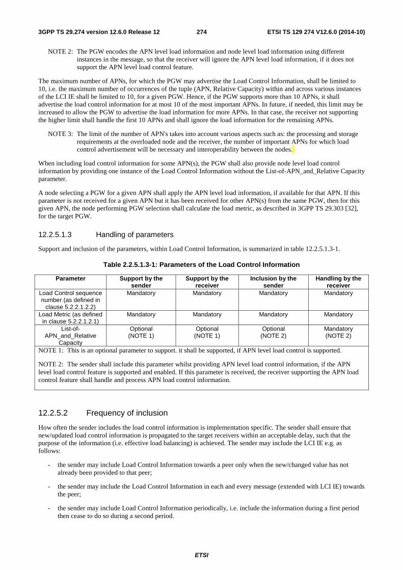
ETSI
ETSI TS 129 274 V12.6.0 (2014-10)2743GPP TS 29.274 version 12.6.0 Release 12
NOTE 2: The PGW encodes the APN level load information and node level load information using different instances in the message, so that the receiver will ignore the APN level load information, if it does not support the APN level load control feature.
The maximum number of APNs, for which the PGW may advertise the Load Control Information, shall be limited to 10, i.e. the maximum number of occurrences of the tuple (APN, Relative Capacity) within and across various instances of the LCI IE shall be limited to 10, for a given PGW. Hence, if the PGW supports more than 10 APNs, it shall advertise the load control information for at most 10 of the most important APNs. In future, if needed, this limit may be increased to allow the PGW to advertise the load information for more APNs. In that case, the receiver not supporting the higher limit shall handle the first 10 APNs and shall ignore the load information for the remaining APNs.
NOTE 3: The limit of the number of APN's takes into account various aspects such as: the processing and storage requirements at the overloaded node and the receiver, the number of important APNs for which load control advertisement will be necessary and interoperability between the nodes.
When including load control information for some APN(s), the PGW shall also provide node level load control information by providing one instance of the Load Control Information without the List-of-APN_and_Relative Capacity parameter.
A node selecting a PGW for a given APN shall apply the APN level load information, if available for that APN. If this parameter is not received for a given APN but it has been received for other APN(s) from the same PGW, then for this given APN, the node performing PGW selection shall calculate the load metric, as described in 3GPP TS 29.303 [32], for the target PGW.
12.2.5.1.3 Handling of parameters
Support and inclusion of the parameters, within Load Control Information, is summarized in table 12.2.5.1.3-1.
Table 2.2.5.1.3-1: Parameters of the Load Control Information
Parameter Support by the sender
Support by the receiver
Inclusion by the sender
Handling by the receiver
Load Control sequence number (as defined in
clause 5.2.2.1.2.2)
Mandatory Mandatory Mandatory Mandatory
Load Metric (as defined in clause 5.2.2.1.2.1)
Mandatory Mandatory Mandatory Mandatory
List-of-APN_and_Relative
Capacity
Optional (NOTE 1)
Optional (NOTE 1)
Optional (NOTE 2)
Mandatory (NOTE 2)
NOTE 1: This is an optional parameter to support. it shall be supported, if APN level load control is supported.
NOTE 2: The sender shall include this parameter whilst providing APN level load control information, if the APN level load control feature is supported and enabled. If this parameter is received, the receiver supporting the APN load control feature shall handle and process APN load control information.
12.2.5.2 Frequency of inclusion
How often the sender includes the load control information is implementation specific. The sender shall ensure that new/updated load control information is propagated to the target receivers within an acceptable delay, such that the purpose of the information (i.e. effective load balancing) is achieved. The sender may include the LCI IE e.g. as follows:
- the sender may include Load Control Information towards a peer only when the new/changed value has not already been provided to that peer;
- the sender may include the Load Control Information in each and every message (extended with LCI IE) towards the peer;
- the sender may include Load Control Information periodically, i.e. include the information during a first period then cease to do so during a second period.
ETSI
ETSI TS 129 274 V12.6.0 (2014-10)2753GPP TS 29.274 version 12.6.0 Release 12
The sender may also implement a combination of one or more of the above approaches. Besides, the sender may also decide to include the Load Control Information only in a subset of the applicable GTP-C messages.
The receiver shall be prepared to receive the load control information in any of the GTP-C messages extended with an LCI IE and upon such reception, shall be able act upon the received load control information.
12.2.5.3 Limit on maximum number of instances
A GTP-C entity may signal one or multiple instances of the LCI IE, with each providing load control information for a different scope. In order to limit the processing of the message on the receiver side and the size of the message on transport level, the number of load control information instances shall be limited:
- at message level: there shall be at most one instance of node level LCI IE per node (i.e. per SGW or PGW) and at most 10 APN level instances.
- at node level: the maximum number of instances of LCI IE which may be provided across multiple messages by a given node shall be the same as the maximum number of instances of LCI IE at message level.
12.2.6 Discovery of the support of the feature by the peer node
A GTP-C entity shall determine whether to use the load control feature (i.e. provide or handle load control information)
- within the PLMN, based on the operator's policy (local PLMN-wide configuration);
- across PLMNs boundary, based on the operator's policy (local configuration per PLMN).
NOTE: The feature may be activated when all or some of the nodes in the PLMN support the feature. The GTP-C entity assumes that all of the peer nodes support this feature when the feature is activated, i.e. it does not need to determine which peers support the feature.
The above operator policy/local configuration may allow the use of load control at node level, load control at node level and APN level, or none.
12.2.7 Issues in the network with partial support of the feature
The Load Control feature should be supported homogenously across all the SGWs and PGWs in the network. Not supporting this feature homogeneously across the SGWs and PGWs may result in poor load balancing in the network such that the SGWs or PGWs not supporting the feature may operate near their maximum capacity (thus being more vulnerable to overload conditions) while SGWs or PGWs supporting the feature have free capacity.
The Load Control feature should be supported homogenously across all the MMEs, S4-SGSNs, ePDGs and TWANs. However, use of the feature when not all of these nodes support the feature may not necessarily create a problem since the load may remain fairly balanced across the SGWs and PGWs assuming that the network imbalance caused by the non-supporting node may get rectified by the supporting nodes making use of dynamic load information while selecting the SGWs and PGWs.
12.3 Overload control solution
12.3.1 Principles of overload control
The stage 2 requirements on GTP-C overload control are defined in clause 4.3.7.1a.2 of 3GPP TS 23.401 [3] and clause 5.3.6.1a of 3GPP TS 23.060 [35]. The high level principles are summarized below:
a) Overload control is an optional feature;
b) a GTP-C entity may signal its overload to its GTP-C peers by including Overload Control Information in GTP-C signalling which provides guidance to the receiving GTP-C entity to decide actions which lead to signalling traffic mitigation towards the sender of the information;
c) the Overload Control Information may provide the overload information of a GTP-C entity, e.g. a PGW, or a specific APN(s) associated with the GTP-C entity;
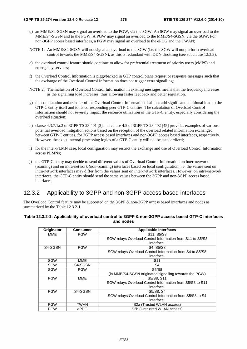
ETSI
ETSI TS 129 274 V12.6.0 (2014-10)2763GPP TS 29.274 version 12.6.0 Release 12
d) an MME/S4-SGSN may signal an overload to the PGW, via the SGW. An SGW may signal an overload to the MME/S4-SGSN and to the PGW. A PGW may signal an overload to the MME/S4-SGSN, via the SGW. For non-3GPP access based interfaces, a PGW may signal an overload to the ePDG and the TWAN;
NOTE 1: An MME/S4-SGSN will not signal an overload to the SGW (i.e. the SGW will not perform overload control towards the MME/S4-SGSN), as this is redundant with DDN throttling (see subclause 12.3.3).
e) the overload control feature should continue to allow for preferential treatment of priority users (eMPS) and emergency services;
f) the Overload Control Information is piggybacked in GTP control plane request or response messages such that the exchange of the Overload Control Information does not trigger extra signalling;
NOTE 2: The inclusion of Overload Control Information in existing messages means that the frequency increases as the signalling load increases, thus allowing faster feedback and better regulation.
g) the computation and transfer of the Overload Control Information shall not add significant additional load to the GTP-C entity itself and to its corresponding peer GTP-C entities. The calculation of Overload Control Information should not severely impact the resource utilization of the GTP-C entity, especially considering the overload situation;
h) clause 4.3.7.1a.2 of 3GPP TS 23.401 [3] and clause 4.5 of 3GPP TS 23.402 [45] provides examples of various potential overload mitigation actions based on the reception of the overload related information exchanged between GTP-C entities, for 3GPP access based interfaces and non-3GPP access based interfaces, respectively. However, the exact internal processing logics of a GTP-C entity will not be standardized;
i) for the inter-PLMN case, local configuration may restrict the exchange and use of Overload Control Information across PLMNs;
j) the GTP-C entity may decide to send different values of Overload Control Information on inter-network (roaming) and on intra-network (non-roaming) interfaces based on local configuration, i.e. the values sent on intra-network interfaces may differ from the values sent on inter-network interfaces. However, on intra-network interfaces, the GTP-C entity should send the same values between the 3GPP and non-3GPP access based interfaces;
12.3.2 Applicability to 3GPP and non-3GPP access based interfaces
The Overload Control feature may be supported on the 3GPP & non-3GPP access based interfaces and nodes as summarized by the Table 12.3.2-1.
Table 12.3.2-1: Applicability of overload control to 3GPP & non-3GPP access based GTP-C interfaces and nodes
Originator Consumer Applicable Interfaces MME PGW S11, S5/S8
SGW relays Overload Control Information from S11 to S5/S8 interface.
S4-SGSN PGW S4, S5/S8 SGW relays Overload Control Information from S4 to S5/S8
interface. SGW MME S11 SGW S4-SGSN S4 SGW PGW S5/S8
(in MME/S4-SGSN originated signalling towards the PGW) PGW MME S5/S8, S11
SGW relays Overload Control Information from S5/S8 to S11 interface.
PGW S4-SGSN S5/S8, S4 SGW relays Overload Control Information from S5/S8 to S4
interface. PGW TWAN S2a (Trusted WLAN access) PGW ePDG S2b (Untrusted WLAN access)
ETSI
ETSI TS 129 274 V12.6.0 (2014-10)2773GPP TS 29.274 version 12.6.0 Release 12
NOTE: Refer to Annex D.2 for information on the GTP-C interfaces for which Overload Control is not supported.
12.3.3 Node level overload control
Node level overload control refers to advertising of the overload information at node level, i.e. overload information at node level granularity, and applying the mitigation policies towards the target node based on this information. This helps in preventing severe overload and hence potential breakdown of the GTP-C node.
When a GTP-C entity determines that the offered incoming signalling traffic is growing (or is about to grow) beyond its nominal capacity, it may signal an Overload Control Information IE to instruct its GTP-C peers to reduce the offered load accordingly.
Overload Control is performed independently for each direction between two GTP-C entities. Overload Control may run concurrently, but independently, for each direction between the two GTP-C entities.
Overload control of SGW originated traffic towards the MME/S4-SGSN shall rely on Downlink Data Notification throttling, as specified in subclause 4.3.7.4.1a of 3GPP TS 23.401 [3] and 5.3.6.5 of 3GPP TS 23.060 [35], with the addition that the SGWs should be allowed, by configuration, to throttle DDN requests for low priority, as well as normal priority traffic (the SGW shall then throttle by priority DDN requests for low priority traffic).
12.3.4 APN level overload control
12.3.4.1 General
APN level overload control refers to advertising of the overload information at APN level granularity and hence applying the mitigation policies based on this information to the signalling traffic related to this APN only. Only a PGW may advertise APN level overload information when it detects overload for certain APNs, e.g. based on shortage of internal or external resources for an APN (e.g. IP address pool).
NOTE: When all the internal and external resources, applicable to the APNs, are available for all the APNs served by a PGW, the node level overload information is exactly the same as APN level overload information of that PGW, for each of its APNs, and hence, performing node overload control can be sufficient.
12.3.4.2 Elements of APN overload control
For allowing the effective APN overload control, at least the following information (in addition to the other applicable information for overload control as defined in clause 12.3.5.1.2) are required to be advertised by the source node, as part of the APN level overload information:
APN: The APN for which the source node wants to advertise the overload information;
APN-Overload-Reduction-Metric: It indicates the requested overload reduction for the signalling traffic corresponding to a particular APN, as a percentage. Its computation is implementation dependent and it has the same characteristics as the "Overload-Reduction-Metric", described in clause12.3.5.1.2.1, when applied at APN level.
12.3.5 Overload Control Information
12.3.5.1 Definition
12.3.5.1.1 General description
Within a message, one or multiple instances of the Overload Control Information (OCI) IE may be included by the same GTP-C entity. Each instance shall provide information about the overload condition to allow the receiver to apply mitigation actions which will result in an efficient alleviation of the overload condition at the sender.
The GTP-C entity shall always include the full set of overload control information, i.e. all the node level and APN level applicable instances of the OCI IE, when signalling overload control information in a message for the first time or subsequently towards the receiver, even when only a subset of the overload control information has changed. All the
ETSI
ETSI TS 129 274 V12.6.0 (2014-10)2783GPP TS 29.274 version 12.6.0 Release 12
instances of the OCI IE provided by a given GTP-C entity in a message shall contain the same Overload Control Sequence Number. The Overload Control Sequence Number shall be incremented whenever the overload control information is modified (see subclause 12.3.5.1.2.3).
The receiver shall overwrite any stored overload control information of a peer with the newly received overload control information (received via one or multiple instances of OCI IE) from the same GTP-C peer entity, if the new information is more recent than the old information, e.g. if the receiver has stored 'X' instances of the OCI IE for a peer GTP-C entity, it shall overwrite those 'X' instances with the new set of 'Y' instances received in a message from the same GTP-C peer entity, where X, Y are any integer numbers.
The receiver shall consider all the parameters received in the same instance of the OCI IE in conjunction while applying the overload mitigation action. When more than one instance of the OCI IE is included, the receiver shall consider the parameters included in each instance independently, while applying the overload mitigation action.
The parameters are further described in subclauses 12.3.5.1.2 and 12.3.5.1.3.
Overload control information may be extended with new parameters in future versions of the specification. Any new parameter will have to be categorized as:
- Non-critical optional parameters: the support of these parameters is not critical for the receiver. The receiver can successfully and correctly comprehend the Overload Control Information instance, containing one or more of these parameters, by using the other parameters and ignoring the non-critical optional parameters.
- Critical optional parameters: the support of these parameters is critical for the receiver to correctly comprehend the instance of the Overload Control Information containing one or more of these parameters.
The sender may include one or more non-critical optional parameter(s) within any instance of Overload Control Information, without having the knowledge of the receiver's capability to support the same. However, the sender shall only include one or more critical optional parameter(s) in any instance of Overload Control Information towards a receiver, if the corresponding receiver is known to support these parameter(s). The sender may be aware of this either via signalling methods or by configuration; this will have to be defined when introducing any such new parameter in the future.
Each instance of the OCI shall be associated by default to the GTP-C entity corresponding to the peer node's IP address of the PDN connection, over which the OCI IE is received, i.e. to the IP address received within the "Sender F-TEID for control plane" IE, the "PGW S5/S8/ S2a/S2b F-TEID for GTP based Control Plane interface" IE or within the "MME/S4-SGSN Identifier" IE.
Alternatively, the GW (i.e. SGW and PGW) nodes may send Overload Control Information which is associated with the GW node's identity, i.e. the FQDN or IP address of the GW node received from the HSS or the DNS, the identity determined during the GW selection. In that case, the GW node shall provide an explicit indication that the OCI IE included in the message belongs to the GW node's identity.
12.3.5.1.2 Parameters
12.3.5.1.2.1 Overload Control Sequence Number
The GTP-C protocol requires retransmitted messages to have the same contents as the original message (see clause 7.6). Due to GTP-C retransmissions, the overload control information received by a GTP-C entity at a given time may be less recent than the overload control information already received from the same GTP-C entity. The Overload Control Sequence Number aids in sequencing the overload control information received from an overloaded GTP-C entity. The Overload Control Sequence Number contains a value that indicates the sequence number associated with the Overload Control Information IE. This sequence number shall be used to differentiate between two OCI IEs generated at two different instants, by the same GTP-C entity.
The Overload Control Sequence Number parameter shall be supported (when supporting the overload control feature) and shall always be present in the Overload Control Information IE.
The sender of this information shall increment the Overload Control Sequence Number whenever modifying some information in the OCI IE. The Overload Control Sequence Number shall not be incremented otherwise. The GTP-C entity may use the time, represented in an unsigned integer format, of the generation of the overload control information, to populate the Overload Control Sequence Number.
ETSI
ETSI TS 129 274 V12.6.0 (2014-10)2793GPP TS 29.274 version 12.6.0 Release 12
When multiple instances of the OCI IE are provided in the same message by a given GTP-C enitity, each of the Overload Control Sequence Numbers shall have the same value.
This parameter shall be used by the receiver of the OCI IE to properly collate out-of-order OCI IEs, e.g. due to GTP-C retransmissions. This parameter shall also be used by the receiver of the OCI IE to determine whether the newly received overload control information has changed compared to the overload control information previously received from the same GTP-C entity. If the newly received overload control information has the same Overload Control Sequence Number as the previously received overload control information from the same GTP-C peer, then the receiver may simply discard the newly received overload control information whilst continuing to apply the overload abatement procedures, as per the previous value.
NOTE 1: The timer corresponding to the Period of Validity (see 12.3.5.1.2.2) is not restarted if the newly received overload control information has the same Overload Control Sequence Number as the previously received overload control information. If the overload condition persists and the overloaded GTP-C entity needs to extend the duration during which the overload information applies, the sender needs to provide a new overload control information with an incremented Overload Control Sequence Number (even if the parameters within the overload control information have not changed).
NOTE 2: The GTP-C Sequence Number cannot be used for collating out-of-order overload information as e.g. overload control information may be sent in both GTP-C requests and responses, using independent GTP-C sequence numbering.
If the receiving GTP-C entity already received and stored overload control information, which is still valid, from the overloaded GTP-C entity, the receiving entity shall update its overload control information, only if the Overload-Sequence-Number received in the new overload control information is larger than the value of the Overload Control Sequence Number associated with the stored information. However due to roll-over of the Overload Control Sequence Number or restart of the GTP-C enitity, the Overload Control Sequence Number may be reset to an appropriate base value by the peer GTP-C entity, hence the receiving entity shall be prepared to receive (and process) an Overload Control Sequence Number parameter whose value is less than the previous value.
12.3.5.1.2.2 Period of Validity
The Period of Validity indicates the length of time during which the overload condition specified by the OCI IE is to be considered as valid (unless overridden by subsequent new overload control information).
An overload condition shall be considered as valid from the time the OCI IE is received until the period of validity expires or until another OCI IE with a new set of information (identified using the Overload Control Sequence Number) is received from the same GTP-C entity (at which point the newly received overload control information shall prevail). The timer corresponding to the period of validity shall be restarted each time an OCI IE with a new set of information (identified using the Overload Control Sequence Number) is received. When this timer expires, the last received overload control information shall be considered outdated and obsolete, i.e. any associated overload condition shall be considered to have ceased.
The Period of Validity parameter shall be supported (when supporting overload control).
The Period of Validity parameter achieves the following:
- it avoids the need for the overloaded GTP-C entity to include the Overload Control Information IE in every GTP-C messages it signals to its GTP-C peers when the overload state does not change; thus it minimizes the processing required at the overloaded GTP-C entity and its GTP-C peers upon sending/receiving GTP-C signalling;
- it allows to reset the overload condition after some time in the GTP-C peers having received an overload indication from the overloaded GTP-C entity, e.g. if no signalling traffic takes place between these GTP-C entities for some time due to overload mitigation actions. This also removes the need for the overloaded GTP-C entity to remember the list of GTP-C entities to which it has sent a non-null overload reduction metric and to which it would subsequently need to signal when the overload condition ceases, if the Period of Validity parameter was not defined.
12.3.5.1.2.3 Overload Reduction Metric
The Overload Reduction Metric shall have a value in the range of 0 to 100 (inclusive) which indicates the percentage of traffic reduction the sender of the overload control information requests the receiver to apply. An Overload Reduction
ETSI
ETSI TS 129 274 V12.6.0 (2014-10)2803GPP TS 29.274 version 12.6.0 Release 12
Metric of "0" always indicates that the GTP-C entity is not in overload (that is, no overload abatement procedures need to be applied) for the indicated scope.
Considering the processing requirement of the receiver of the Overload Control Information, e.g. to perform overload control based on the updated Overload Reduction Metric, the sender should refrain from advertising every small variation, e.g. with the granularity of 1 or 2, in the Overload Reduction Metric which does not result in useful improvement for mitigating the overload situation. During the typical operating condition of the sender, a larger variation in the Overload Reduction Metric, e.g. 5 or more units, should be considered as reasonable enough for advertising a new Overload Reduction Metric Information and thus justifying the processing requirement (to handle the new information) of the receiver.
NOTE: The range of Overload Reduction Metric, i.e. 0 to 100, does not mandate the sender to collect its own overload information at every increment/decrement and hence to advertise the change of Overload Reduction Metric with a granularity of 1%. Based on various implementation specific criteria, such as the architecture, session and signalling capacity, the current load/overload situation and so on, the sender is free to define its own logic and periodicity with which its own overload control information is collected.
The computation of the exact value for this parameter is left as an implementation choice at the sending GTP-C entity.
The Overload Reduction Metric shall be supported (when supporting overload control) and shall always be present in the OCI IE.
The inclusion of the OCI IE signals an overload situation is occuring, unless the Overload Reduction Metric is set to 0, which signals that the overload condition has ceased. Conversely, the absence of the OCI IE in a message does not mean that the overload has abated.
12.3.5.1.2.4 List of APNs
The List of APNs indicates one or more APNs for which the Overload Control Information is applicable. When present in the OCI IE, the scope of the overload control information shall be the list of the indicated APNs for the PGW that sends the overload control information. At most one instance of List of APNs shall be included within one Overload Control Information instance.
NOTE 1: The maximum number of APNs in the List of APNs is set to 10. More than 10 occurrences of APN within one single instance of the List of APNs is treated as a protocol error by the receiver.
If the List of APNs has not been included, the scope of the Overload Control Information shall be the entire GTP-C entity (unless restricted by other parameters in the Overload Control Information).
The List of APNs parameter shall be supported (when supporting overload control). The List of APNs may be present or absent in the Overload Control Information IE (depending on the scope of the reported overload control information).
This parameter may be provided by the PGW only and it shall be used by the MME/S4-SGSN and the TWAN/ePDG only.
The maximum number of APNs, for which the PGW may advertise the Overload Control Information, shall be limited to 10, i.e. the maximum number of occurrences of APNs within and across various instances of the Overload Control Information IE shall be limited to 10 for a given PGW. Hence, if the PGW supports more than 10 APNs, it shall advertise the overload control for at most 10 of the most important APNs. In future, if needed, this limit may be increased to allow the PGW to advertise the overload information for more APNs. In that case, the receiver that does not support the higher limit shall only handle the first 10 APNs and ignore the overload information for the remaining APNs to enable future compatibility.
NOTE 2: Considering various aspects such as: the processing and storage requirements at the overloaded GTP-C entity and the receiver, the number of important APNs for which overload control advertisement could be necessary, interoperability between the nodes of various vendors, etc. it was decided to define a limit on maximum number of APNs for advertising the overload control information. It was decided to fix this limit to 10 whilst also ensuring that the mechanism exists to extend this limit in future releases, if required.
12.3.5.1.3 Handling of parameters
Support and inclusion of the parameters, within overload control information, is summarized in table 12.3.5.1.3-1.
ETSI
ETSI TS 129 274 V12.6.0 (2014-10)2813GPP TS 29.274 version 12.6.0 Release 12
Table 12.3.5.1.3-1: Parameters of the Overload Control Information
Parameter Support by the sender
Support by the receiver
Inclusion by the sender
Handling by the receiver
Overload Control Sequence Number (as
defined in clause 12.3.5.1.2.1)
Mandatory Mandatory Mandatory Mandatory
Period of Validity (as defined in clause
12.3.5.1.2.2)
Mandatory Mandatory Mandatory Mandatory
Overload Reduction Metric (as defined in clause 12.3.5.1.2.3)
Mandatory Mandatory Mandatory Mandatory
List of APNs (as defined in clause
12.3.5.1.2.4)
Mandatory Mandatory Optional Mandatory (if provided by the sender)
12.3.5.2 Frequency of inclusion
How often or when the sender includes the overload control information is implementation specific. The sender shall ensure that new/updated overload control information is propagated to the target receivers with an acceptable delay, such that the purpose of the information, (i.e. the effective overload control protection) is achieved. The following are some of the potential approaches the sender may implement for including the OCI IE:
- the sender may include OCI IE towards a receiver only when the new/changed value has not already been provided to the given receiver;
- the sender may include the OCI IE in a subset of the messages towards the receiver;
- the sender may include the OCI IE periodically, i.e. include the information during a first period then cease to do so during a second period.
The sender may also implement a combination of one or more of the above approaches. Besides, the sender may also include the OCI IE only in a subset of the applicable GTP-C messages.
The receiver shall be prepared to receive the overload control information received in any of the GTP-C messages extended with an OCI IE and upon such reception, shall be able act upon the received information.
12.3.5.3 Limit on maximum number of instances
A GTP-C entity may signal one or multiple instances of the OCI IE, each instance providing overload control information for a different scope. The receiver shall handle all these instances, from each of the peer GTP-C entities, by processing, storing and acting upon the same foroverload control. In order to limit the processing of the message on the receiver side and the size of the message, the number of overload control information instances shall be limited:
- at message level: there shall be at most one instance of node-level Overload Control Information IE per node and at most 10 APN-level instances.
- at node level: the maximum number of instances of the OCI IE which may be provided across multiple messages by a given node shall be the same as the maximum number of instances of the OCI IE at message level.
12.3.6 Propagating the MME/S4-SGSN identity to the PGW
When the Overload Control feature is supported by the MME/S4-SGSN and the SGW, and it is also activated for the PLMN to which the PGW belongs, the following shall apply:
- The MME/S4-SGSN shall include the MME/S4-SGSN identity towards the SGW during:
- the PDN connection establishment, any mobility with an MME/S4-SGSN change or any SGW change procedures;
ETSI
ETSI TS 129 274 V12.6.0 (2014-10)2823GPP TS 29.274 version 12.6.0 Release 12
- the dedicated bearer activation procedure, PGW initiated bearer modification procedure and PGW initiated bearer deactivation procedure as per the conditions specified in the corresponding messages.
- The SGW shall forward the MME/S4-SGSN identifier to the PGW if it is received in the Create/Update/Delete Bearer Response messages. When it is received in other GTP-C messages, the SGW shall store the received MME/S4-SGSN identity and shall include the currently serving MME/S4-SGSN's identity in subsequent Modify Bearer Request messages which are sent over the S5/S8 interface, whenever there is signalling over the S5/S8 interface.
NOTE: This allows updating of the PGW with the identity of the new MME/S4-SGSN during inter-MME/SGSN mobility scenarios as early as possible and without generating extra signalling over the S5/S8 interface. Inter-MME/inter-SGSN intra SGW mobility scenarios not requiring to send any S5/S8 signalling could result in the PGW not being updated with the currently serving MME/S4-SGSN's identity, for a given subscriber, until subsequent S5/S8 signalling takes place for the same PDN connection. However, considering these scenarios are not so frequent and considering that several features anyway require S5/S8 signalling during these scenarios (e.g. for user location reporting), the PGW will most often get the identity of the currently serving MME/S4-SGSN. Hence the risk that the PGW wrongly throttles PGW initiated signalling for that PDN connection, if the old MME/S4-SGSN is in overload, is low.
- The PGW shall store the currently serving MME/S4-SGSN identity, received from the SGW, to be able to reduce the PGW initiated signalling messages for the PDN connections during an overload situation at the serving MME/S4-SGSN.
12.3.7 Updating the PGW with overload control information of the target MME/S4-SGSN
During inter-MME/S4-SGSN mobility without SGW change scenarios, the SGW shall forward the MME/S4-SGSN's overload control information over the S5/S8 interface only if the Modify Bearer Request message needs to be sent over the S5/S8 for another reason, e.g. if the ULI, CGI, Serving Network, needs to be reported to the PGW, i.e. the SGW shall not generate a Modify Bearer Request message over the S5/S8 interface for the sole purpose of reporting the MME/S4-SGSN's overload control information. This avoids generating extra signalling over the S5/S8 interface.
NOTE: If the MME/S4-SGSN provides overload control information during the scenarios which do not result in S5/S8 signaling, e.g. during an inter MME/S4-SGSN and intra SGW mobility, when no other information such as: the ULI, CGI or Serving Network, needs to be reported to the PGW, the overload information will not be relayed on to the PGW. Hence, the MME/S4-SGSN needs consider this when including overload control information.
12.3.8 The interaction with APN congestion control using the PGW Back-Off Time
When detecting that a given APN is congested, the PGW shall either use the PGW Back-Off Time mechanism (see subclause 4.3.7.5 of 3GPP TS 23.401 [3]) or the APN level overload control mechanism (i.e. providing an Overload Control Information IE with an APN-List included) for that APN, but not both together for the same APN, e.g. if the PGW provides an Overload Control Information IE with an APN-List set to "APN1", it shall not reject Create Session Request messages for "APN1" with a PGW Back-Off Time until the Period-Of-Validity of the overload information previously sent has expired.
The PGW may however use both mechanisms concurrently for different APNs, e.g. the PGW may reject Create Session Request messages for the"APN2" with a PGW Back-Off Time IE, if the APN2 is also congested and if there is no on-going APN-level overload control mechanism for that APN.
When rejecting a Create Session Request due to APN congestion, the PGW shall set the "APN Congestion" cause, regardless of the aforementioned mechanisms.
If the MME/S4-SGSN or ePDG/TWAN has one mechanism active for a given APN and PGW, (e.g. an MME has received a PGW Back-Off Time) and if subsequently it receives information for the same APN and PGW for another mechanism, (e.g. the MME receives an Overload Control Info IE with APN-List included for the same APN), then it shall deactivate/stop the earlier mechanism and consider only the information received for the latter mechanism.
Different PGWs may use concurrently different mechanisms for the same APN.
ETSI
ETSI TS 129 274 V12.6.0 (2014-10)2833GPP TS 29.274 version 12.6.0 Release 12
12.3.9 Message throttling
12.3.9.1 General
As part of the overload mitigation, a GTP-C entity shall reduce the total number of messages, which would have been sent otherwise, towards the overloaded peer based on the information received within the Overload Control Information. This shall be achieved by discarding a fraction of the messages in proportion to the overload level of the target peer. This is called message throttling.
Message throttling shall only apply to initial messages. Triggered request or response messages should not be throttled since that would result in the retransmission of the corresponding request message by the sender.
Before piggybacking the initial message over a response message, the initial message should be subject to the message throttling in the similar manner as any other non-piggybacked initial message. If the node decides to throttle this initial message then the response message should be sent without any piggyback message.
A GTP-C entity supporting GTP-C overload control shall support and use the "Loss" algorithm as specified in this clause, for message throttling.
12.3.9.2 Throttling algorithm – "Loss"
12.3.9.2.1 Description
An overloaded GTP-C entity shall ask its peers to reduce the number of requests they would ordinarily send by signalling Overload Control Information including the requested traffic reduction, as a percentage, within the "Overload-Reduction-Metric", as specified in clause 12.3.5.1.2.1.
The recipients of the "Overload-Reduction-Metric" shall reduce the number of requests sent by that percentage, either by redirecting them to an alternate destination if possible (e.g. the Create Session Request message may be redirected to an alternate SGW/PGW), or by failing the request and treating it as if it was rejected by the destination GTP-C entity.
For example, if a sender requests another peer to reduce the traffic it is sending by 10%, then that peer shall throttle 10% of the traffic that would have otherwise been sent to this GTP-C entity.
The overloaded GTP-C entity should periodically adjust the requested traffic reduction based e.g. on the traffic reduction factor that is currently in use, the current system utilization (i.e. the overload level) and the desired system utilization (i.e. the target load level), and/or the rate of the current overall received traffic.
Annex D.3.1 provides an (informative) example of a possible implementation of the "Loss" algorithm, amongst other possible methods.
NOTE 1: This algorithm does not guarantee that the future traffic towards the overloaded GTP-C entity will be less than the past traffic but it ensures that the total traffic sent towards the overloaded GTP-C entity is less than what would have been sent without any throttling in place. If after requesting a certain reduction in traffic, the overloaded GTP-C entity receives more traffic than in the past, whilst still in overload, leading to the worsening rather than an improvement in the overload level, then the overloaded GTP-C entity can request for more reduction in traffic. Thus, by periodically adjusting the requested traffic reduction, the overloaded node can ensure that it receives, approximately, the amount of traffic which it can handle.
NOTE 2: Since the reduction is requested as a percentage, and not as an absolute amount, this algorithm achieves a good useful throughput towards the overloaded node when the traffic conditions vary at the source nodes (depending upon the events generated towards these source nodes by other entities in the network), as a potential increase of traffic from some source nodes can possibly be compensated by a potential decrease of traffic from other source nodes.
12.3.9.3 Message prioritization
12.3.9.3.1 Description
When performing message throttling:
ETSI
ETSI TS 129 274 V12.6.0 (2014-10)2843GPP TS 29.274 version 12.6.0 Release 12
- all the procedures for emergency and priority users (eMPS) related sessions should be treated with the highest priority. Hence all the messages belonging to those types of sessions should be given the least preference while performing message throttling;
- for other types of sessions, messages throttling should consider the relative priority of the messages so that the messages which are considered as low priority are considered for throttling before the other messages. The relative priority of the messages may be derived from the relative priority of the procedure for which the message is being sent (as specified in subclause 12.3.9.3.2) or may be derived from the session parameters (as specified in subclause 12.3.9.3.3).
NOTE: A random throttling mechanism, i.e. discarding the messages without any special consideration, could result in an overall poor congestion mitigation mechanism and bad user experience.
An overloaded node may also apply these message prioritization schemes when handling incoming initial messages during an overloaded condition, as part of the self-protection mechanism (see subclause 12.3.10.2.3).
12.3.9.3.2 Based on procedures
Message prioritization may be performed based on the relative priority of the procedure for which the message is being sent. Procedures are grouped into various categories and each of these categories is assigned a priority. Additionally, within a given category of procedures, messages may be further prioritized based on session parameters such as: APN, QCI, ARP and/or LAPI (as described in subclause 12.3.9.3.3).
Subsequently, messages with a high priority shall be given lower preference to throttle and messages with low priority shall be given higher preference to throttle.
The grouping of the procedures is not performed based on an individual GTP-C entity but whilst considering all the procedures in general. A GTP-C entity should consider the procedures applicable to it and apply prioritized message throttling based on the category of the procedure, as described below. The categories are listed in decreasing order of priority with category 1 having the highest priority. For each category a non-exhaustive list of messages is provided. Any existing or newly defined message in future should be considered based on the category (as specified below) of the procedure for which the message is sent.
1. UE session mobility within and across 3GPP or non-3GPP access: Procedures involving active or idle mode UE mobility, such that GTP-C signalling is involved, shall be classified under this category. Some examples are X2/S1 based handover with/without an SGW change, TAU/RAU with a change of MME/SGSN with/without an SGW change, 3GPP access to trusted non-3GPP access handover, etc. Throttling of these messages, during the procedures related to UE session mobility, would result in the failure of the corresponding procedures. This could result potentially in the loss of the PDN connection and/or the interruption of the services. Hence, the messages, as identified below, when sent during the procedures belonging to this category, shall be considered with the highest priority and hence, shall be given the lowest preference to throttle.
- Create Session Request,
- Create Session Request with "handover" indication bit set,
- Modify Bearer Request,
- Modify Bearer Request with "handover" indication bit set,
- Modify Access Bearer Request.
2. Release of PDN connection or bearer resources: Procedures resulting in the deactivation of an existing PDN connection, the deactivation of bearer(s) or of data forwarding tunnel of an UE leads to freeing up of the resources at the overloaded node and hence, can potentially ease the overload situation, since the freed up resources can be used for serving the remaining of the UEs. Thus, the messages belonging to this category resulting in the deactivation of PDN connection or bearer(s) or data forwarding tunnel(s), as identified below, shall be treated with the next lower level of priority and hence shall be given the corresponding preference whilst throttling:
- Delete Session Request,
- Delete Bearer Request,
- Delete Bearer Command,
ETSI
ETSI TS 129 274 V12.6.0 (2014-10)2853GPP TS 29.274 version 12.6.0 Release 12
- Delete Indirect Data Forwarding Tunnel Request.
3. Miscellaneous session management procedures: This category shall consist of the session management procedures, except PDN connection creation and bearer creation/modification procedures. Some examples are location reporting, when it is not combined with other mobility procedures, Service request and S1 release procedure. These procedures do not severely impact the on-going service of the UE. Hence, the messages, as identified below, when sent during the procedures identified under this category, shall be treated with the next lower level of priority and hence, shall be given the corresponding preference whilst throttling:
- Release Access Bearer Request,
- Modify Bearer Request,
- Change Notification,
- Suspend Notification,
- Resume Notification.
4. Request for new PDN Connection or bearer resources: Procedures requesting the creation of PDN connection, creation or modification of bearer(s) or creation of data forwarding tunnel shall be classified in this category. Throttling of the messages belonging to this category would result in denial of new services while continuing with the existing services. However, this is the natural outcome of an overload condition, i.e. the overloaded node, due to lack of resources, is not able to provision new services while the trying to maintain the existing services and hence, the messages, as identified below, when sent during the procedures belonging to this category, shall be considered with the lowest level of priority and hence shall be given highest preference to throttle:
- Create Session Request during PDN connection request,
- Create Bearer Request,
- Update Bearer Request,
- Bearer Resource Command,
- Modify Bearer Command,
- Create Indirect Data Forwarding Tunnel Request.
12.3.9.3.3 Based on session parameters
Message prioritization may be performed based on the session parameters, such as: APN, QCI, ARP and/or Low Access Priority Indicator (LAPI). The procedures and messages associated with the higher priority sessions shall be given lesser preference whilst throttling, as compared to the procedures and messages associated with the lower priority sessions. Within each group of sessions, the messages may be further prioritized based on the category of the procedure for which the message is being sent (as described in subclause 12.3.9.3.2).
NOTE: This type of prioritization scheme ensures a good handling of all the messages and procedures related to higher priority sessions but can lead to throttle messages related to a critical procedure, e.g. UE mobility, for lower priority sessions over messages related to less critical procedures, e.g. location reporting, for a higher priority session.
12.3.10 Enforcement of overload control
12.3.10.1 General
When a GTP-C entity receives Overload Control Information from its peer, it shall apply the overload abatement algorithm, based on the received information, for the messages sent towards the peer GTP-C entity. This is called "enforcement of overload control" and it involves throttling of the messages targeted for the overloaded peer.
ETSI
ETSI TS 129 274 V12.6.0 (2014-10)2863GPP TS 29.274 version 12.6.0 Release 12
12.3.10.2 Aspects related to enforcement of the overload control
12.3.10.2.1 Good throughput of the network
A source GTP-C entity should avoid any mechanism resulting in over throttling of the messages. Enforcement of the overload control whilst ensuring that good throughput (i.e. measured in terms of the rate of total number of messages the overloaded GTP-C entity can successfully process) of the network remains consistent to that when no overload control is applied, should be one of the prime objective of the source GTP-C entity.
NOTE: Over throttling of messages would negatively affect end user services and cause potential additional signalling in the network e.g. if the corresponding procedure is retried at a later time.
12.3.10.2.2 Message processing efficiency at the source GTP-C entity
Enforcement of overload control requires extra logic and extra processing at the source GTP-C entity. This is an overhead since the source GTP-C entity has to spend its resources in an activity other than processing of the messages. Hence, the implementation as well as the processing complexity of the enforcement of the overload control, should not result in a significantly poorer efficiency of the source GTP-C entity.
12.3.10.2.3 Self-protection by the overloaded GTP-C entity
A source GTP-C entity enforcing the overload control cannot ensure that the overloaded peer will not receive more messages than what it can handle during the overload condition, e.g. the "loss" algorithm does not guarantee that the future traffic reaches perfectly that requested by the overloaded GTP-C entity. Hence, the overloaded target GTP-C entity shall protect itself from the risk of meltdown even in a network where all the sending GTP-C entities support the overload control mechanism. As a part of this self-protection, the overloaded target GTP-C entity may reject the messages which it cannot handle during an overloaded state. A GTP-C entity which decides to not process an incoming request message due to overload should still send a reject response message, if possible, indicating the temporary unavailability of the resources; otherwise the request message may be dropped.
NOTE: Without a response message, the source GTP-C entity cannot determine whether the request did not reach the target GTP-C entity due to a network error or whether the target GTP-C entity was in overload and not able to process the request and send a response message. This will cause the source GTP-C entity to retransmit the request message and hence will increase further the overload at the target node.
While rejecting the message due to overload, the GTP-C entity shall set the cause to "GTP-C Entity Congestion" or "APN congestion" (for node level or APN level overload respectively) and may include the Overload Control Information in the rejection response as specified in subclauses 12.3.5.1.1 and 12.3.11.
12.3.10.3 Enforcement of overload control between GTP-C entities in direct contact
A source GTP-C entity shall enforce overload control for traffic destined to a GTP-C entity in direct contact based on the overload reduction metric received from that peer, e.g. the MME applies the overload control for the messages targeted for the SGW based on the overload information of the SGW.
12.3.10.4 Enforcement of overload control between remote GTP-C entities
12.3.10.4.1 Description
For messages destined to a remote GTP-C entity (i.e. a GTP-C entity not in direct contact but reached via an intermediate GTP-C entity), the source GTP-C entity shall enforce the overload control based on the overload information of the target of the message, as well as the overload information of the intermediate GTP-C entity, e.g. the MME applies the overload control for messages targeted for the PGW based on the overload information of the SGW and PGW.
For the received messages, the intermediate GTP-C entity shall not further enforce any overload control and hence, shall not reject any message towards the source GTP-C entity.
Annex D.4.1 provides an (informative) example of a possible implementation.
NOTE 1: This approach ensures the overload protection of the Target as well as Intermediate GTP-C entities.
ETSI
ETSI TS 129 274 V12.6.0 (2014-10)2873GPP TS 29.274 version 12.6.0 Release 12
NOTE 2: The source GTP-C entity may be connected to the same Target GTP-C entity via multiple different Intermediate GTP-C entities. The exact algorithm used at the source GTP-C entity to enforce the overload control, as per the aforementioned requirements, is implementation specific.
12.3.11 Discovery of the support of the feature by the peer node
A GTP-C entity shall determine whether to use the overload control feature:
- within the PLMN, based on operator's policy (local PLMN-wide configuration);
- across PLMNs boundary, based on operator's policy (local configuration per PLMN).
NOTE: The feature can be activated when all or some of the nodes in the PLMN support the feature. The GTP-C entity assumes that all the peer nodes support this feature when the feature is activated, i.e. it does not need to determine which peers support the feature.
The above operator policy/local configuration may allow the use of overload control at node level and APN level, or none.
12.3.12 Issues in the network with partial support of the feature
The Overload Control feature should be supported homogenously across the nodes in the network, otherwise:
- an overloaded node will get messages beyond its acceptable processing capacity, even after announcing its overload status. This may result in severe overload and possibly a breakdown of the node;
- a non-supporting node will get an unfair advantage in sending all the messages to an overloaded node, whereas a supporting node, would be requested to throttle more messages.
12.3.13 Implicit overload control mechanisms
Implicit overload control mechanisms are mechanisms used between GTP-C entities when GTP-C overload control is not supported or not enabled between them, e.g. across PLMN boundary based on operator's policy, to help reducing the overload at the overloaded node:
- a GTP-C entity which decides to not process an incoming request message due to overload should still send a reject response message, if possible, indicating the temporary unavailability of the resources, e.g. No resources available; otherwise the GTP-C entity may drop the incoming request message.
NOTE: Without a response message, the source GTP-C entity cannot determine whether the request did not reach the target GTP-C entity due to a network error or whether the target GTP-C entity was in overload and not able to process the request and send a response message. This will cause the source GTP-C entity to retransmit the request message and hence will increase further the overload at the target node.
- a GTP-C entity in overload may support messages throttling as a self protection mechanism and may apply message prioritization as described in subclause 12.3.9 when selecting the incoming request messages to be throttled;
- based on the number and rate of reject responses indicating temporary unavailability of resources, e.g. No resources available, a source GTP-C entity should try to assess the overload level of the target GTP-C entity and apply correspondingly message throttling as described in subclause 12.3.9 to reduce the amount of traffic sent towards the overloaded GTP-C entity.
ETSI
ETSI TS 129 274 V12.6.0 (2014-10)2883GPP TS 29.274 version 12.6.0 Release 12
Annex A (Informative): Backward Compatibility Guidelines for Information Elements In order to preserve backward compatibility, the following rules should apply when adding or modifying information elements for existing messages.
- No new mandatory (M) information elements should be added.
- No new conditional (C) information elements should be added.
- Any new IEs should be either:
optional (O), having no conditions on their presence, or
conditional-optional (CO), having conditions that should apply only to the sender and not to the receiver.
Such conditions should be worded generally as follows: "This IE shall be sent over the xxx interface <condition>. The receiving entity need not check the IE's presence."
- If any new conditions are added to a previously specified conditional (C) information element, these new conditions should apply only to the sender and not to the receiver. Such additional conditions should be worded generally as follows: "This IE shall be sent over the xxx interface <condition>. For this optional condition, the receiving entity need not check the IE's presence." Existing conditions for such conditional (C) IEs should be treated as before, and the presence of the IEs should remain conditional (C).
ETSI
ETSI TS 129 274 V12.6.0 (2014-10)2893GPP TS 29.274 version 12.6.0 Release 12
Annex B (Informative): Transparent copying of RANAP/S1AP IEs into GTP IEs
B.1 General This annex provides details on how a GTPv2 entity transparently copies information received from RANAP or S1AP into GTPv2 IE or IE field.
RANAP and S1AP ASN.1 encoding details in this annex are informative. The reference specifications are 3GPP TS 25.413 [33] and 3GPP TS 36.413 [10] respectively.
The respective RANAP/S1AP Information Elements are transported on the Iu/S1 interface within a "protocol-IE container" which is composed of:
- an Information Element Identity (referred to below as "IE-ID"),
- an indication how the receiver shall react if the Information Element is not comprehended (referred to below as "criticality"),
- and an "open type field" which consists of a length indication ("OT-LI") and the Information Element itself (referred to below as "IE").
RANAP/S1AP PDUs and the contained IEs are defined by means of ASN.1, the specified encoding is PER (packed encoding rule), Octet aligned variant:
- PER minimises the information sent on the respective interface to the absolute minimum;
- Hence, type definitions of fixed length are encoded without any type or length indication, only type definitions of variable length contain a length indication, e.g.
- an OCTET STRING with indefinite length would need to contain a length indication (referred to below as "OCT-LI") followed by the actual octets (referred to below as "octets");
- a SEQUENCE neither contains a type, nor a length-indication. Only in case of optional elements it contains a kind of bit string with each position of this bitstring indicating the presence of an OPTIONAL element (an encoded SEQUENCE type is referred to below as "sequence").
B.2 Handover/Relocation related generic transparent Containers over RANAP, S1-AP and GTP
Handover/Relocation related generic transparent containers are defined in 3GPP TS 25.413 [33] and 3GPP TS 36.413 [10] ("Source to Target Transparent Container" IE and "Target to Source Transparent Container" IE) to carry UTRAN, E-UTRAN or GERAN specific information via CN interfaces in a RAT-agnostic way.
The encoding of these handover/relocation related generic transparent containers is different in RANAP and S1-AP. See 3GPP TS 36.413 [10] Annex C. The difference is that the "Source to Target Transparent Container" IE and "Target to Source Transparent Container" IE are ASN.1 encoded over RANAP as "IE-ID||criticality||OT-LI||octets" (i.e. one length field only for the open type field) and over S1AP as "IE-ID||criticality||OT-LI||OCT-LI||octets" (i.e. with 2 length fields, one for the open type field ("OT-LI"), one for the octet string encoding ("OCT-LI")), while "octets" contain the actual RAT specific handover/relocation information.
This gives the following chain of encodings (represented in the notation introduced in the Notes above) end-to-end.
LTE to LTE
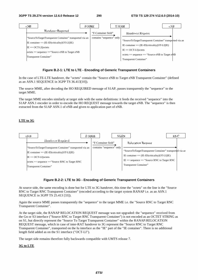
ETSI
ETSI TS 129 274 V12.6.0 (2014-10)2903GPP TS 29.274 version 12.6.0 Release 12
S-MME eNB
Handover Required
eNB
Handover Request
T-MME
“F-Container field”
contains “sequence” only “SourceToTargetTransparent Container” transported via an
IE container == (IE-ID|criticality||OT-LI||IE)
IE == OCT-LI||octets
octets == sequence ==”Source eNB to Target eNB
Transparent Container”
“SourceToTargetTransparent Container” transported via an
IE container == (IE-ID|criticality||OT-LI||IE)
IE == OCT-LI||octets
octets == sequence == “Source eNB to Target eNB
Transparent Container”
Figure B.2-1: LTE to LTE - Encoding of Generic Transparent Containers
In the case of LTE-LTE handover, the "octets" contain the "Source eNB to Target eNB Transparent Container" (defined as an ASN.1 SEQUENCE in 3GPP TS 36.413[10]).
The source MME, after decoding the HO REQUIRED message of S1AP, passes transparently the "sequence" to the target MME.
The target MME encodes similarly at target side with the same definitions: it feeds the received "sequence" into the S1AP ASN.1 encoder in order to encode the HO REQUEST message towards the target eNB. The "sequence" is then extracted from the S1AP ASN.1 of eNB and given to application part of eNB.
LTE to 3G
S-MME RNC
Handover Required
eNB
Relocation Request
SGSN
“F-Container field”
contains “sequence” only “SourceToTargetTransparent Container” transported via an
IE container == (IE-ID|criticality||OT-LI||IE)
IE == OCT-LI||octets
octets == sequence ==”Source RNC to Target RNC
Transparent Container”
“SourceToTargetTransparent Container” transported via an
IE container == (IE-ID|criticality||OT-LI||IE)
IE == sequence == “Source RNC to Target RNC
Transparent Container”
Figure B.2-2: LTE to 3G - Encoding of Generic Transparent Containers
At source side, the same encoding is done but for LTE to 3G handover, this time the "octets" on the line is the "Source RNC to Target RNC Transparent Container" (encoded according to the target system RANAP i.e. as an ASN.1 SEQUENCE in 3GPP TS 25.413 [33]).
Again the source MME passes transparently the "sequence" to the target MME i.e. the "Source RNC to Target RNC Transparent Container".
At the target side, the RANAP RELOCATION REQUEST message was not upgraded: the "sequence" received from the Gn or S3 interface ("Source RNC to Target RNC Transparent Container") is not encoded as an OCTET STRING as on S1, but directly represent the "Source To Target Transparent Container" within the RANAP:RELOCATION REQUEST message, which in case of inter-RAT handover to 3G represent the "Source RNC to Target RNC Transparent Container", transported on the Iu interface as the "IE" part of the "IE container". There is no additional length field added as on the S1 interface ("OCT-LI").
The target side remains therefore fully backwards compatible with UMTS release 7.
3G to LTE
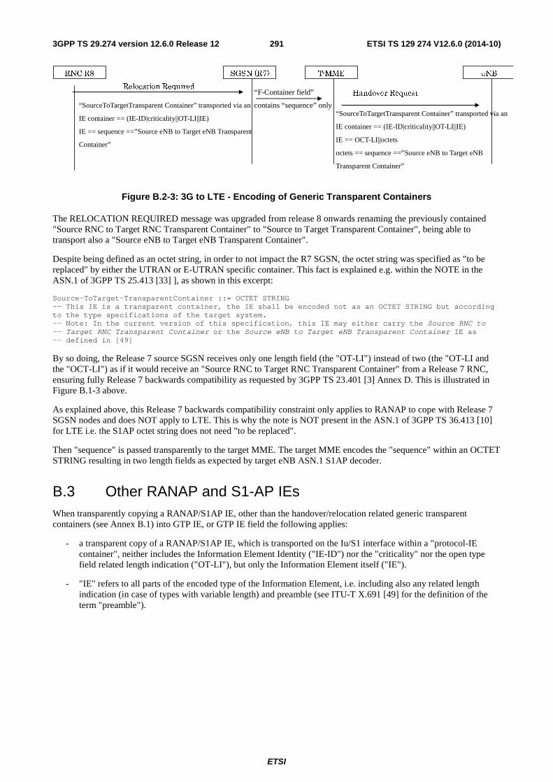
ETSI
ETSI TS 129 274 V12.6.0 (2014-10)2913GPP TS 29.274 version 12.6.0 Release 12
SGSN (R7) eNB
Relocation Required
RNC R8
Handover Request
T-MME
“SourceToTargetTransparent Container” transported via an
IE container == (IE-ID|criticality||OT-LI||IE)
IE == sequence ==”Source eNB to Target eNB Transparent
Container”
“F-Container field”
contains “sequence” only “SourceToTargetTransparent Container” transported via an
IE container == (IE-ID|criticality||OT-LI||IE)
IE == OCT-LI||octets
octets == sequence ==”Source eNB to Target eNB
Transparent Container”
Figure B.2-3: 3G to LTE - Encoding of Generic Transparent Containers
The RELOCATION REQUIRED message was upgraded from release 8 onwards renaming the previously contained "Source RNC to Target RNC Transparent Container" to "Source to Target Transparent Container", being able to transport also a "Source eNB to Target eNB Transparent Container".
Despite being defined as an octet string, in order to not impact the R7 SGSN, the octet string was specified as "to be replaced" by either the UTRAN or E-UTRAN specific container. This fact is explained e.g. within the NOTE in the ASN.1 of 3GPP TS 25.413 [33] ], as shown in this excerpt:
Source-ToTarget-TransparentContainer ::= OCTET STRING -- This IE is a transparent container, the IE shall be encoded not as an OCTET STRING but according to the type specifications of the target system. -- Note: In the current version of this specification, this IE may either carry the Source RNC to -- Target RNC Transparent Container or the Source eNB to Target eNB Transparent Container IE as -- defined in [49]
By so doing, the Release 7 source SGSN receives only one length field (the "OT-LI") instead of two (the "OT-LI and the "OCT-LI") as if it would receive an "Source RNC to Target RNC Transparent Container" from a Release 7 RNC, ensuring fully Release 7 backwards compatibility as requested by 3GPP TS 23.401 [3] Annex D. This is illustrated in Figure B.1-3 above.
As explained above, this Release 7 backwards compatibility constraint only applies to RANAP to cope with Release 7 SGSN nodes and does NOT apply to LTE. This is why the note is NOT present in the ASN.1 of 3GPP TS 36.413 [10] for LTE i.e. the S1AP octet string does not need "to be replaced".
Then "sequence" is passed transparently to the target MME. The target MME encodes the "sequence" within an OCTET STRING resulting in two length fields as expected by target eNB ASN.1 S1AP decoder.
B.3 Other RANAP and S1-AP IEs When transparently copying a RANAP/S1AP IE, other than the handover/relocation related generic transparent containers (see Annex B.1) into GTP IE, or GTP IE field the following applies:
- a transparent copy of a RANAP/S1AP IE, which is transported on the Iu/S1 interface within a "protocol-IE container", neither includes the Information Element Identity ("IE-ID") nor the "criticality" nor the open type field related length indication ("OT-LI"), but only the Information Element itself ("IE").
- "IE" refers to all parts of the encoded type of the Information Element, i.e. including also any related length indication (in case of types with variable length) and preamble (see ITU-T X.691 [49] for the definition of the term "preamble").
ETSI
ETSI TS 129 274 V12.6.0 (2014-10)2923GPP TS 29.274 version 12.6.0 Release 12
Annex C (Normative): MME/S4-SGSN mapping table between S11/S4 and NAS Cause values The MME/S4-SGSN initiates session management requests towards the SGW and PGW or mobility management requests towards the source/target MME/S4-SGSN. If this operation is not successful, there are several possible cause codes, which need to be mapped to the appropriate cause codes over NAS to the UE.
Additionally, the MME/S4-SGSN initiates session management requests towards the UE. If this operation is not successful, there are several possible NAS cause codes which need to be mapped to the appropriate GTP cause codes over S11/S4 interface towards the SGW.
The MME/S4-SGSN should map these cause codes as defined in tables C.1 to C.5 unless specified otherwise in the tables.
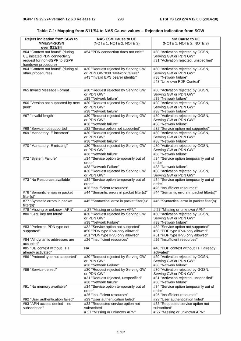
ETSI
ETSI TS 129 274 V12.6.0 (2014-10)2933GPP TS 29.274 version 12.6.0 Release 12
Table C.1: Mapping from S11/S4 to NAS Cause values – Rejection indication from SGW
Reject indication from SGW to MME/S4-SGSN
over S11/S4
NAS ESM Cause to UE (NOTE 1, NOTE 2, NOTE 3)
SM Cause to UE (NOTE 1, NOTE 2, NOTE 3)
#64 "Context not found" (during UE initiated PDN connectivity request for non-3GPP to 3GPP handover procedure)
#54 "PDN connection does not exist" #30 "Activation rejected by GGSN, Serving GW or PDN GW" #31 "Activation rejected, unspecified"
#64 "Context not found" (during all other procedures)
#30 "Request rejected by Serving GW or PDN GW"#38 "Network failure" #43 "Invalid EPS bearer identity"
#30 "Activation rejected by GGSN, Serving GW or PDN GW" #38 "Network failure" #43 "Unknown PDP Context"
#65 Invalid Message Format #30 "Request rejected by Serving GW or PDN GW" #38 "Network failure"
#30 "Activation rejected by GGSN, Serving GW or PDN GW" #38 "Network failure"
#66 "Version not supported by next peer"
#30 "Request rejected by Serving GW or PDN GW" #38 "Network failure"
#30 "Activation rejected by GGSN, Serving GW or PDN GW" #38 "Network failure"
#67 "Invalid length" #30 "Request rejected by Serving GW or PDN GW" #38 "Network failure"
#30 "Activation rejected by GGSN, Serving GW or PDN GW" #38 "Network failure"
#68 "Service not supported" #32 "Service option not supported" #32 "Service option not supported" #69 "Mandatory IE incorrect" #30 "Request rejected by Serving GW
or PDN GW" #38 "Network failure"
#30 "Activation rejected by GGSN, Serving GW or PDN GW" #38 "Network failure"
#70 "Mandatory IE missing" #30 "Request rejected by Serving GW or PDN GW" #38 "Network failure"
#30 "Activation rejected by GGSN, Serving GW or PDN GW" #38 "Network failure"
#72 "System Failure" #34 "Service option temporarily out of order" #38 "Network Failure" #30 "Request rejected by Serving GW or PDN GW"
#34 "Service option temporarily out of order" #38 "Network failure" #30 "Activation rejected by GGSN, Serving GW or PDN GW"
#73 "No Resources available" #34 "Service option temporarily out of order" #26 "Insufficient resources"
#34 "Service option temporarily out of order" #26 "Insufficient resources"
#76 "Semantic errors in packet filter(s)"
#44 "Semantic errors in packet filter(s)" #44 "Semantic errors in packet filter(s)"
#77 "Syntactic errors in packet filter(s)"
#45 "Syntactical error in packet filter(s)" #45 "Syntactical error in packet filter(s)"
#78 "Missing or unknown APN" # 27 "Missing or unknown APN" # 27 "Missing or unknown APN" #80 "GRE key not found" #30 "Request rejected by Serving GW
or PDN GW" #38 "Network Failure"
#30 "Activation rejected by GGSN, Serving GW or PDN GW" #38 "Network failure"
#83 "Preferred PDN type not supported"
#32 "Service option not supported" #50 "PDN type IPv4 only allowed" #51 "PDN type IPv6 only allowed"
#32 "Service option not supported" #50 "PDP type IPv4 only allowed" #51 "PDP type IPv6 only allowed"
#84 "All dynamic addresses are occupied"
#26 "Insufficient resources" #26 "Insufficient resources"
#85 "UE context without TFT already activated"
NA #46 "PDP context without TFT already activated"
#86 "Protocol type not supported" #30 "Request rejected by Serving GW or PDN GW" #38 "Network Failure"
#30 "Activation rejected by GGSN, Serving GW or PDN GW" #38 "Network failure"
#89 "Service denied"
#30 "Request rejected by Serving GW or PDN GW" #31 "Request rejected, unspecified" #38 "Network failure"
#30 "Activation rejected by GGSN, Serving GW or PDN GW" #31 "Activation rejected, unspecified" #38 "Network failure"
#91 "No memory available" #34 "Service option temporarily out of order" #26 "Insufficient resources"
#34 "Service option temporarily out of order" #26 "Insufficient resources"
#92 "User authentication failed" #29 "User authentication failed" #29 "User authentication failed" #93 "APN access denied – no subscription"
#33 "Requested service option not subscribed" # 27 "Missing or unknown APN"
#33 "Requested service option not subscribed" # 27 "Missing or unknown APN"
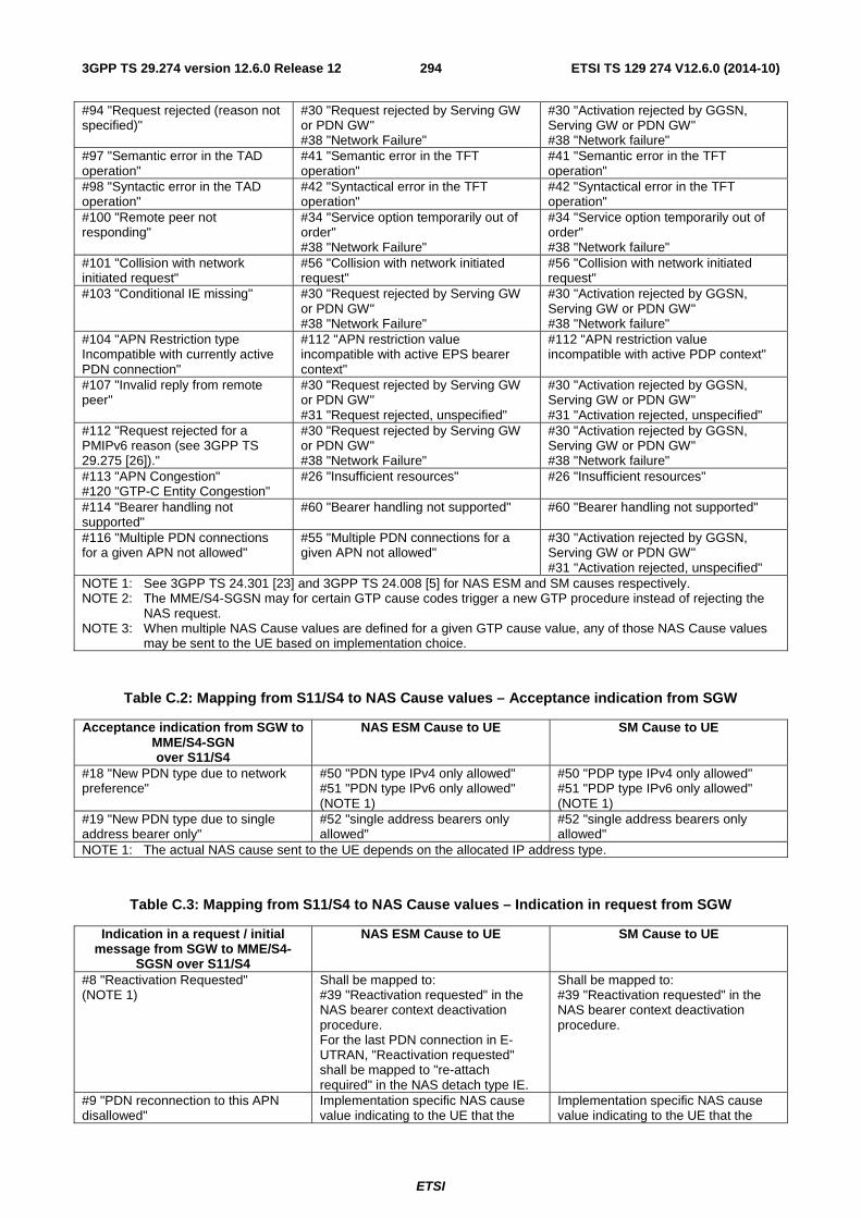
ETSI
ETSI TS 129 274 V12.6.0 (2014-10)2943GPP TS 29.274 version 12.6.0 Release 12
#94 "Request rejected (reason not specified)"
#30 "Request rejected by Serving GW or PDN GW" #38 "Network Failure"
#30 "Activation rejected by GGSN, Serving GW or PDN GW" #38 "Network failure"
#97 "Semantic error in the TAD operation"
#41 "Semantic error in the TFT operation"
#41 "Semantic error in the TFT operation"
#98 "Syntactic error in the TAD operation"
#42 "Syntactical error in the TFT operation"
#42 "Syntactical error in the TFT operation"
#100 "Remote peer not responding"
#34 "Service option temporarily out of order" #38 "Network Failure"
#34 "Service option temporarily out of order" #38 "Network failure"
#101 "Collision with network initiated request"
#56 "Collision with network initiated request"
#56 "Collision with network initiated request"
#103 "Conditional IE missing" #30 "Request rejected by Serving GW or PDN GW" #38 "Network Failure"
#30 "Activation rejected by GGSN, Serving GW or PDN GW" #38 "Network failure"
#104 "APN Restriction type Incompatible with currently active PDN connection"
#112 "APN restriction value incompatible with active EPS bearer context"
#112 "APN restriction value incompatible with active PDP context"
#107 "Invalid reply from remote peer"
#30 "Request rejected by Serving GW or PDN GW" #31 "Request rejected, unspecified"
#30 "Activation rejected by GGSN, Serving GW or PDN GW" #31 "Activation rejected, unspecified"
#112 "Request rejected for a PMIPv6 reason (see 3GPP TS 29.275 [26])."
#30 "Request rejected by Serving GW or PDN GW" #38 "Network Failure"
#30 "Activation rejected by GGSN, Serving GW or PDN GW" #38 "Network failure"
#113 "APN Congestion" #120 "GTP-C Entity Congestion"
#26 "Insufficient resources" #26 "Insufficient resources"
#114 "Bearer handling not supported"
#60 "Bearer handling not supported" #60 "Bearer handling not supported"
#116 "Multiple PDN connections for a given APN not allowed"
#55 "Multiple PDN connections for a given APN not allowed"
#30 "Activation rejected by GGSN, Serving GW or PDN GW" #31 "Activation rejected, unspecified"
NOTE 1: See 3GPP TS 24.301 [23] and 3GPP TS 24.008 [5] for NAS ESM and SM causes respectively. NOTE 2: The MME/S4-SGSN may for certain GTP cause codes trigger a new GTP procedure instead of rejecting the
NAS request. NOTE 3: When multiple NAS Cause values are defined for a given GTP cause value, any of those NAS Cause values
may be sent to the UE based on implementation choice.
Table C.2: Mapping from S11/S4 to NAS Cause values – Acceptance indication from SGW
Acceptance indication from SGW to MME/S4-SGN over S11/S4
NAS ESM Cause to UE SM Cause to UE
#18 "New PDN type due to network preference"
#50 "PDN type IPv4 only allowed" #51 "PDN type IPv6 only allowed" (NOTE 1)
#50 "PDP type IPv4 only allowed" #51 "PDP type IPv6 only allowed" (NOTE 1)
#19 "New PDN type due to single address bearer only"
#52 "single address bearers only allowed"
#52 "single address bearers only allowed"
NOTE 1: The actual NAS cause sent to the UE depends on the allocated IP address type.
Table C.3: Mapping from S11/S4 to NAS Cause values – Indication in request from SGW
Indication in a request / initial message from SGW to MME/S4-
SGSN over S11/S4
NAS ESM Cause to UE SM Cause to UE
#8 "Reactivation Requested" (NOTE 1)
Shall be mapped to: #39 "Reactivation requested" in the NAS bearer context deactivation procedure. For the last PDN connection in E-UTRAN, "Reactivation requested" shall be mapped to "re-attach required" in the NAS detach type IE.
Shall be mapped to: #39 "Reactivation requested" in the NAS bearer context deactivation procedure.
#9 "PDN reconnection to this APN disallowed"
Implementation specific NAS cause value indicating to the UE that the
Implementation specific NAS cause value indicating to the UE that the
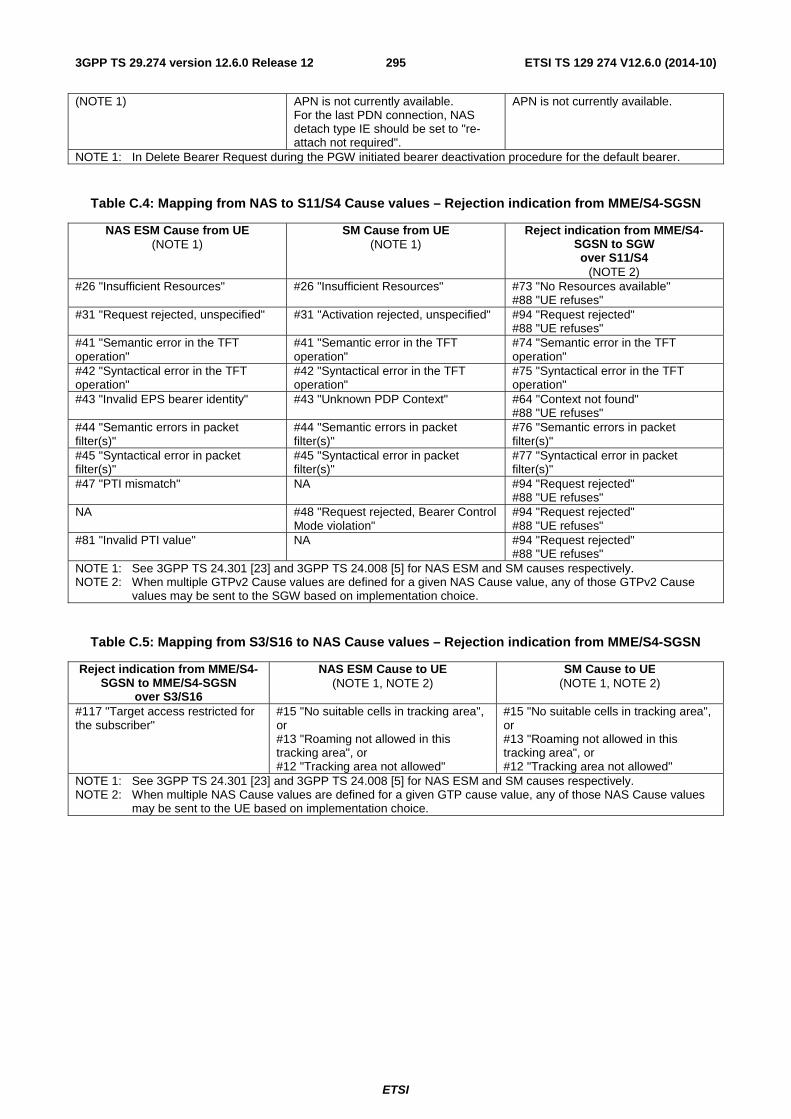
ETSI
ETSI TS 129 274 V12.6.0 (2014-10)2953GPP TS 29.274 version 12.6.0 Release 12
(NOTE 1) APN is not currently available. For the last PDN connection, NAS detach type IE should be set to "re-attach not required".
APN is not currently available.
NOTE 1: In Delete Bearer Request during the PGW initiated bearer deactivation procedure for the default bearer.
Table C.4: Mapping from NAS to S11/S4 Cause values – Rejection indication from MME/S4-SGSN
NAS ESM Cause from UE (NOTE 1)
SM Cause from UE (NOTE 1)
Reject indication from MME/S4-SGSN to SGW over S11/S4
(NOTE 2) #26 "Insufficient Resources" #26 "Insufficient Resources" #73 "No Resources available"
#88 "UE refuses" #31 "Request rejected, unspecified" #31 "Activation rejected, unspecified" #94 "Request rejected"
#88 "UE refuses" #41 "Semantic error in the TFT operation"
#41 "Semantic error in the TFT operation"
#74 "Semantic error in the TFT operation"
#42 "Syntactical error in the TFT operation"
#42 "Syntactical error in the TFT operation"
#75 "Syntactical error in the TFT operation"
#43 "Invalid EPS bearer identity" #43 "Unknown PDP Context" #64 "Context not found" #88 "UE refuses"
#44 "Semantic errors in packet filter(s)"
#44 "Semantic errors in packet filter(s)"
#76 "Semantic errors in packet filter(s)"
#45 "Syntactical error in packet filter(s)"
#45 "Syntactical error in packet filter(s)"
#77 "Syntactical error in packet filter(s)"
#47 "PTI mismatch" NA #94 "Request rejected" #88 "UE refuses"
NA #48 "Request rejected, Bearer Control Mode violation"
#94 "Request rejected" #88 "UE refuses"
#81 "Invalid PTI value" NA #94 "Request rejected" #88 "UE refuses"
NOTE 1: See 3GPP TS 24.301 [23] and 3GPP TS 24.008 [5] for NAS ESM and SM causes respectively. NOTE 2: When multiple GTPv2 Cause values are defined for a given NAS Cause value, any of those GTPv2 Cause
values may be sent to the SGW based on implementation choice.
Table C.5: Mapping from S3/S16 to NAS Cause values – Rejection indication from MME/S4-SGSN
Reject indication from MME/S4-SGSN to MME/S4-SGSN
over S3/S16
NAS ESM Cause to UE (NOTE 1, NOTE 2)
SM Cause to UE (NOTE 1, NOTE 2)
#117 "Target access restricted for the subscriber"
#15 "No suitable cells in tracking area", or #13 "Roaming not allowed in this tracking area", or #12 "Tracking area not allowed"
#15 "No suitable cells in tracking area", or #13 "Roaming not allowed in this tracking area", or #12 "Tracking area not allowed"
NOTE 1: See 3GPP TS 24.301 [23] and 3GPP TS 24.008 [5] for NAS ESM and SM causes respectively. NOTE 2: When multiple NAS Cause values are defined for a given GTP cause value, any of those NAS Cause values
may be sent to the UE based on implementation choice.
ETSI
ETSI TS 129 274 V12.6.0 (2014-10)2963GPP TS 29.274 version 12.6.0 Release 12
Annex D (Informative): GTP-C load and overload control mechanism
D.1 GTP-C interfaces not supporting Load Control Load Control has been designed as a generic mechanism possibly applicable to any GTP-C node. However, for the reasons clarified below, in the current release, Load Control is not supported for the following GTP-C based interfaces:
- S3, S10, S16 (limited GTP-C signalling traffic, to minimize impact to the MME/S4-SGSN);
- Sm, Sn (limited GTP-C signalling traffic, to avoid impact to the MBMS GW);
- Sv (limited GTP-C signalling traffic, to avoid impact to the legacy CS products);
- S101, S121 (to avoid impacts to the legacy HRPD products);
- Gn/Gp (to avoid impact to the legacy Gn-SGSN/GGSN products and GTPv1-C protocol).
D.2 GTP-C interfaces not supporting Overload Control Overload Control has been designed as a generic mechanism possibly applicable to any GTP-C based interface and any direction. However for the reasons clarified below, in the current release, Overload Control is not supported for the following GTP-C based interfaces:
- S3, S10, S16 (see considerations below, to minimize impact to MME and S4-SGSN);
- most of the S3 traffic would remain internal to the combo-node with the deployment of combo-MME/S4-SGSN nodes. The traffic over S10/S16 is also reduced with the deployment of MME and SGSN pools. It is therefore not essential to throttle the traffic on these interfaces when an MME or S4-SGSN experiences overload;
- throttling signalling on these interfaces resulting from a user's mobility (inter-MME/S4-SGSN TAU, RAU and Handover) would result in bad end user's perception (handover failure, loss of PDN connections) and so needs to be avoided as far as possible;
- an MME or S4-SGSN in overload may drop locally incoming RIM messages without causing GTP-C retransmissions (although this may cause the RAN to retransmit the message).
- S11/S4 (from an MME/S4-SGSN to an SGW, with SGW as consumer; see consideration below);
- by allowing the SGW to throttle DDN requests for normal priority traffic, the overload control of the messages originated by the SGW towards the MME/S4-SGSN is covered and hence, an SGW performing overload control towards the MME/S4-SGSN using Overload Control Information would be redundant.
- S5/S8 (from a PGW to an SGW, with the SGW as a consumer; no signalling message, originated by the SGW towards the PGW, that is identified as requiring overload control);
- Sm, Sn (no overload scenario identified, limited GTP-C traffic, to avoid impact to the MBMS GW);
- Sv (no overload scenario identified, to avoid impact to the legacy CS products);
- S101, S121 (no overload scenario identified, to avoid impact to the legacy HRPD products);
- Gn/Gp (to avoid impact to the legacy Gn-SGSN/GGSN products and GTPv1-C protocol);
- S2a (from the TWAN to the PGW, with the PGW as a consumer; no overload scenario identified);
- S2b (from the ePDG to the PGW, with the PGW as a consumer; no overload scenario identified).
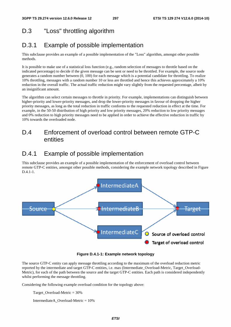
ETSI
ETSI TS 129 274 V12.6.0 (2014-10)2973GPP TS 29.274 version 12.6.0 Release 12
D.3 "Loss" throttling algorithm
D.3.1 Example of possible implementation This subclause provides an example of a possible implementation of the "Loss" algorithm, amongst other possible methods.
It is possible to make use of a statistical loss function (e.g., random selection of messages to throttle based on the indicated percentage) to decide if the given message can be sent or need to be throttled. For example, the source node generates a random number between (0, 100) for each message which is a potential candidate for throttling. To realize 10% throttling, messages with a random number 10 or less are throttled and hence this achieves approximately a 10% reduction in the overall traffic. The actual traffic reduction might vary slightly from the requested percentage, albeit by an insignificant amount.
The algorithm can select certain messages to throttle in priority. For example, implementations can distinguish between higher-priority and lower-priority messages, and drop the lower-priority messages in favour of dropping the higher priority messages, as long as the total reduction in traffic conforms to the requested reduction in effect at the time. For example, in the 50-50 distribution of high priority and low priority messages, 20% reduction to low priority messages and 0% reduction to high priority messages need to be applied in order to achieve the effective reduction in traffic by 10% towards the overloaded node.
D.4 Enforcement of overload control between remote GTP-C entities
D.4.1 Example of possible implementation This subclause provides an example of a possible implementation of the enforcement of overload control between remote GTP-C entities, amongst other possible methods, considering the example network topology described in Figure D.4.1-1.
Figure D.4.1-1: Example network topology
The source GTP-C entity can apply message throttling according to the maximum of the overload reduction metric reported by the intermediate and target GTP-C entities, i.e. max (Intermediate_Overload-Metric, Target_Overload-Metric), for each of the path between the source and the target GTP-C entities. Each path is considered independently whilst performing the message throttling.
Considering the following example overload condition for the topology above:
Target_Overload-Metric = 30%
IntermediateA_Overload-Metric = 10%
ETSI
ETSI TS 129 274 V12.6.0 (2014-10)2983GPP TS 29.274 version 12.6.0 Release 12
IntermediateB_Overload-Metric = 20%
IntermediateC_Overload-Metric = 40%
Target_Terminated-Messages = 100
IntermediateA-Target_Messages = 20
IntermediateB-Target_Messages = 50
IntermediateC-Target_Messages = 30
the source GTP-C entity applies message throttling as follows:
Source-IntermediateA_Messages = 14 (message throttling of 30% applied)
Source-IntermediateB_Messages = 35 (message throttling of 30% applied)
Source-IntermediateC_Messages = 18 (message throttling of 40% applied)
Source-Target_Messages = 67 (the Target GTP-C entity receives 67 messages although it could have handled 70 messages in the overloaded condition).
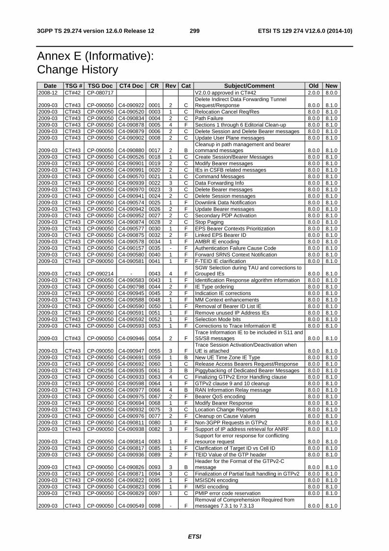
ETSI
ETSI TS 129 274 V12.6.0 (2014-10)2993GPP TS 29.274 version 12.6.0 Release 12
Annex E (Informative): Change History
Date TSG # TSG Doc CT4 Doc CR Rev Cat Subject/Comment Old New 2008-12 CT#42 CP-080717 V2.0.0 approved in CT#42 2.0.0 8.0.0
2009-03 CT#43 CP-090050 C4-090922 0001 2 C Delete Indirect Data Forwarding Tunnel Request/Response 8.0.0 8.1.0
2009-03 CT#43 CP-090050 C4-090520 0003 1 C Relocation Cancel Req/Res 8.0.0 8.1.0 2009-03 CT#43 CP-090050 C4-090834 0004 2 C Path Failure 8.0.0 8.1.0 2009-03 CT#43 CP-090050 C4-090878 0005 4 F Sections 1 through 6 Editorial Clean-up 8.0.0 8.1.0 2009-03 CT#43 CP-090050 C4-090879 0006 2 C Delete Session and Delete Bearer messages 8.0.0 8.1.0 2009-03 CT#43 CP-090050 C4-090902 0008 2 C Update User Plane messages 8.0.0 8.1.0
2009-03 CT#43 CP-090050 C4-090880 0017 2 B Cleanup in path management and bearer command messages 8.0.0 8.1.0
2009-03 CT#43 CP-090050 C4-090526 0018 1 C Create Session/Bearer Messages 8.0.0 8.1.0 2009-03 CT#43 CP-090050 C4-090901 0019 2 C Modify Bearer messages 8.0.0 8.1.0 2009-03 CT#43 CP-090050 C4-090991 0020 2 C IEs in CSFB related messages 8.0.0 8.1.0 2009-03 CT#43 CP-090050 C4-090570 0021 1 C Command Messages 8.0.0 8.1.0 2009-03 CT#43 CP-090050 C4-090939 0022 3 C Data Forwarding Info 8.0.0 8.1.0 2009-03 CT#43 CP-090050 C4-090970 0023 3 C Delete Bearer messages 8.0.0 8.1.0 2009-03 CT#43 CP-090050 C4-090941 0024 2 C Delete Session messages 8.0.0 8.1.0 2009-03 CT#43 CP-090050 C4-090574 0025 1 F Downlink Data Notification 8.0.0 8.1.0 2009-03 CT#43 CP-090050 C4-090942 0026 2 F Update Bearer messages 8.0.0 8.1.0 2009-03 CT#43 CP-090050 C4-090952 0027 2 C Secondary PDP Activation 8.0.0 8.1.0 2009-03 CT#43 CP-090050 C4-090874 0028 2 C Stop Paging 8.0.0 8.1.0 2009-03 CT#43 CP-090050 C4-090577 0030 1 F EPS Bearer Contexts Prioritization 8.0.0 8.1.0 2009-03 CT#43 CP-090050 C4-090875 0032 2 F Linked EPS Bearer ID 8.0.0 8.1.0 2009-03 CT#43 CP-090050 C4-090578 0034 1 F AMBR IE encoding 8.0.0 8.1.0 2009-03 CT#43 CP-090050 C4-090157 0035 - F Authentication Failure Cause Code 8.0.0 8.1.0 2009-03 CT#43 CP-090050 C4-090580 0040 1 F Forward SRNS Context Notification 8.0.0 8.1.0 2009-03 CT#43 CP-090050 C4-090581 0041 1 F F-TEID IE clarification 8.0.0 8.1.0
2009-03 CT#43 CP-090214 - 0043 4 F SGW Selection during TAU and corrections to Grouped IEs 8.0.0 8.1.0
2009-03 CT#43 CP-090050 C4-090583 0043 1 F Identification Response algorithm information 8.0.0 8.1.0 2009-03 CT#43 CP-090050 C4-090798 0044 2 F IE Type ordering 8.0.0 8.1.0 2009-03 CT#43 CP-090050 C4-090945 0045 2 F Indication IE corrections 8.0.0 8.1.0 2009-03 CT#43 CP-090050 C4-090588 0048 1 F MM Context enhancements 8.0.0 8.1.0 2009-03 CT#43 CP-090050 C4-090590 0050 1 F Removal of Bearer ID List IE 8.0.0 8.1.0 2009-03 CT#43 CP-090050 C4-090591 0051 1 F Remove unused IP Address IEs 8.0.0 8.1.0 2009-03 CT#43 CP-090050 C4-090592 0052 1 F Selection Mode bits 8.0.0 8.1.0 2009-03 CT#43 CP-090050 C4-090593 0053 1 F Corrections to Trace Information IE 8.0.0 8.1.0
2009-03 CT#43 CP-090050 C4-090946 0054 2 F Trace Information IE to be included in S11 and S5/S8 messages 8.0.0 8.1.0
2009-03 CT#43 CP-090050 C4-090947 0055 3 F Trace Session Activation/Deactivation when UE is attached 8.0.0 8.1.0
2009-03 CT#43 CP-090050 C4-090691 0059 1 B New UE Time Zone IE Type 8.0.0 8.1.0 2009-03 CT#43 CP-090050 C4-090692 0060 1 C Release Access Bearers Request/Response 8.0.0 8.1.0 2009-03 CT#43 CP-090256 C4-090935 0061 3 B Piggybacking of Dedicated Bearer Messages 8.0.0 8.1.0 2009-03 CT#43 CP-090050 C4-090933 0063 4 C Finalizing GTPv2 Error Handling clause 8.0.0 8.1.0 2009-03 CT#43 CP-090050 C4-090598 0064 1 F GTPv2 clause 9 and 10 cleanup 8.0.0 8.1.0 2009-03 CT#43 CP-090050 C4-090977 0066 4 B RAN Information Relay message 8.0.0 8.1.0 2009-03 CT#43 CP-090050 C4-090975 0067 2 F Bearer QoS encoding 8.0.0 8.1.0 2009-03 CT#43 CP-090050 C4-090694 0068 1 F Modify Bearer Response 8.0.0 8.1.0 2009-03 CT#43 CP-090050 C4-090932 0075 3 C Location Change Reporting 8.0.0 8.1.0 2009-03 CT#43 CP-090050 C4-090976 0077 2 F Cleanup on Cause Values 8.0.0 8.1.0 2009-03 CT#43 CP-090050 C4-090811 0080 1 F Non-3GPP Requests in GTPv2 8.0.0 8.1.0 2009-03 CT#43 CP-090050 C4-090938 0082 3 F Support of IP address retrieval for ANRF 8.0.0 8.1.0
2009-03 CT#43 CP-090050 C4-090814 0083 1 F Support for error response for conflicting resource request 8.0.0 8.1.0
2009-03 CT#43 CP-090050 C4-090817 0085 1 F Clarification of Target ID vs Cell ID 8.0.0 8.1.0 2009-03 CT#43 CP-090050 C4-090936 0089 2 F TEID Value of the GTP header 8.0.0 8.1.0
2009-03 CT#43 CP-090050 C4-090826 0093 3 B Header for the Format of the GTPv2-C message 8.0.0 8.1.0
2009-03 CT#43 CP-090050 C4-090871 0094 3 C Finalization of Partial fault handling in GTPv2 8.0.0 8.1.0 2009-03 CT#43 CP-090050 C4-090822 0095 1 F MSISDN encoding 8.0.0 8.1.0 2009-03 CT#43 CP-090050 C4-090823 0096 1 F IMSI encoding 8.0.0 8.1.0 2009-03 CT#43 CP-090050 C4-090829 0097 1 C PMIP error code reservation 8.0.0 8.1.0
2009-03 CT#43 CP-090050 C4-090549 0098 - F Removal of Comprehension Required from messages 7.3.1 to 7.3.13 8.0.0 8.1.0
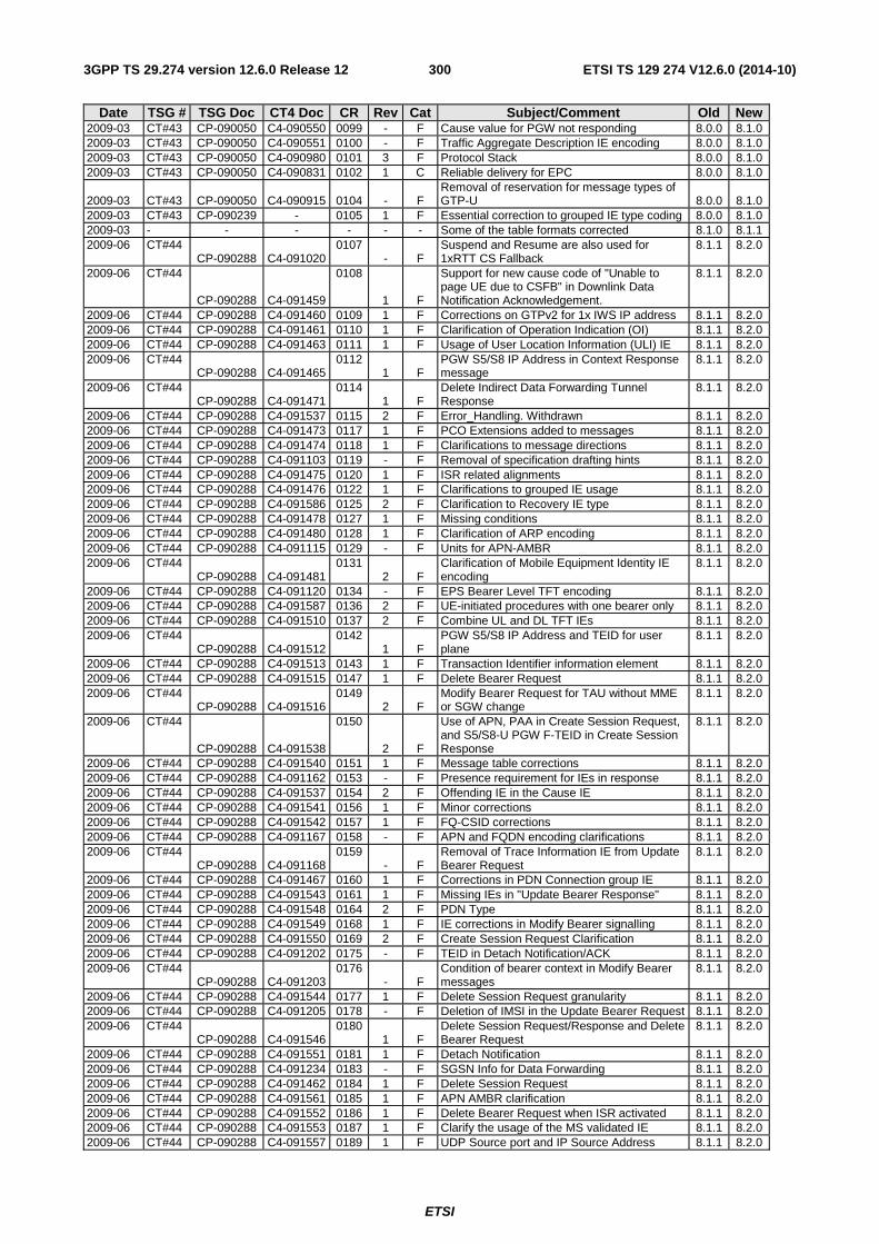
ETSI
ETSI TS 129 274 V12.6.0 (2014-10)3003GPP TS 29.274 version 12.6.0 Release 12
Date TSG # TSG Doc CT4 Doc CR Rev Cat Subject/Comment Old New 2009-03 CT#43 CP-090050 C4-090550 0099 - F Cause value for PGW not responding 8.0.0 8.1.0 2009-03 CT#43 CP-090050 C4-090551 0100 - F Traffic Aggregate Description IE encoding 8.0.0 8.1.0 2009-03 CT#43 CP-090050 C4-090980 0101 3 F Protocol Stack 8.0.0 8.1.0 2009-03 CT#43 CP-090050 C4-090831 0102 1 C Reliable delivery for EPC 8.0.0 8.1.0
2009-03 CT#43 CP-090050 C4-090915 0104 - F Removal of reservation for message types of GTP-U 8.0.0 8.1.0
2009-03 CT#43 CP-090239 - 0105 1 F Essential correction to grouped IE type coding 8.0.0 8.1.0 2009-03 - - - - - - Some of the table formats corrected 8.1.0 8.1.1 2009-06 CT#44
CP-090288 C4-091020 0107
- F Suspend and Resume are also used for 1xRTT CS Fallback
8.1.1 8.2.0
2009-06 CT#44
CP-090288 C4-091459
0108
1 F
Support for new cause code of "Unable to page UE due to CSFB" in Downlink Data Notification Acknowledgement.
8.1.1 8.2.0
2009-06 CT#44 CP-090288 C4-091460 0109 1 F Corrections on GTPv2 for 1x IWS IP address 8.1.1 8.2.0 2009-06 CT#44 CP-090288 C4-091461 0110 1 F Clarification of Operation Indication (OI) 8.1.1 8.2.0 2009-06 CT#44 CP-090288 C4-091463 0111 1 F Usage of User Location Information (ULI) IE 8.1.1 8.2.0 2009-06 CT#44
CP-090288 C4-091465 0112
1 F PGW S5/S8 IP Address in Context Response message
8.1.1 8.2.0
2009-06 CT#44 CP-090288 C4-091471
0114 1 F
Delete Indirect Data Forwarding Tunnel Response
8.1.1 8.2.0
2009-06 CT#44 CP-090288 C4-091537 0115 2 F Error_Handling. Withdrawn 8.1.1 8.2.0 2009-06 CT#44 CP-090288 C4-091473 0117 1 F PCO Extensions added to messages 8.1.1 8.2.0 2009-06 CT#44 CP-090288 C4-091474 0118 1 F Clarifications to message directions 8.1.1 8.2.0 2009-06 CT#44 CP-090288 C4-091103 0119 - F Removal of specification drafting hints 8.1.1 8.2.0 2009-06 CT#44 CP-090288 C4-091475 0120 1 F ISR related alignments 8.1.1 8.2.0 2009-06 CT#44 CP-090288 C4-091476 0122 1 F Clarifications to grouped IE usage 8.1.1 8.2.0 2009-06 CT#44 CP-090288 C4-091586 0125 2 F Clarification to Recovery IE type 8.1.1 8.2.0 2009-06 CT#44 CP-090288 C4-091478 0127 1 F Missing conditions 8.1.1 8.2.0 2009-06 CT#44 CP-090288 C4-091480 0128 1 F Clarification of ARP encoding 8.1.1 8.2.0 2009-06 CT#44 CP-090288 C4-091115 0129 - F Units for APN-AMBR 8.1.1 8.2.0 2009-06 CT#44
CP-090288 C4-091481 0131
2 F Clarification of Mobile Equipment Identity IE encoding
8.1.1 8.2.0
2009-06 CT#44 CP-090288 C4-091120 0134 - F EPS Bearer Level TFT encoding 8.1.1 8.2.0 2009-06 CT#44 CP-090288 C4-091587 0136 2 F UE-initiated procedures with one bearer only 8.1.1 8.2.0 2009-06 CT#44 CP-090288 C4-091510 0137 2 F Combine UL and DL TFT IEs 8.1.1 8.2.0 2009-06 CT#44
CP-090288 C4-091512 0142
1 F PGW S5/S8 IP Address and TEID for user plane
8.1.1 8.2.0
2009-06 CT#44 CP-090288 C4-091513 0143 1 F Transaction Identifier information element 8.1.1 8.2.0 2009-06 CT#44 CP-090288 C4-091515 0147 1 F Delete Bearer Request 8.1.1 8.2.0 2009-06 CT#44
CP-090288 C4-091516 0149
2 F Modify Bearer Request for TAU without MME or SGW change
8.1.1 8.2.0
2009-06 CT#44
CP-090288 C4-091538
0150
2 F
Use of APN, PAA in Create Session Request, and S5/S8-U PGW F-TEID in Create Session Response
8.1.1 8.2.0
2009-06 CT#44 CP-090288 C4-091540 0151 1 F Message table corrections 8.1.1 8.2.0 2009-06 CT#44 CP-090288 C4-091162 0153 - F Presence requirement for IEs in response 8.1.1 8.2.0 2009-06 CT#44 CP-090288 C4-091537 0154 2 F Offending IE in the Cause IE 8.1.1 8.2.0 2009-06 CT#44 CP-090288 C4-091541 0156 1 F Minor corrections 8.1.1 8.2.0 2009-06 CT#44 CP-090288 C4-091542 0157 1 F FQ-CSID corrections 8.1.1 8.2.0 2009-06 CT#44 CP-090288 C4-091167 0158 - F APN and FQDN encoding clarifications 8.1.1 8.2.0 2009-06 CT#44
CP-090288 C4-091168 0159
- F Removal of Trace Information IE from Update Bearer Request
8.1.1 8.2.0
2009-06 CT#44 CP-090288 C4-091467 0160 1 F Corrections in PDN Connection group IE 8.1.1 8.2.0 2009-06 CT#44 CP-090288 C4-091543 0161 1 F Missing IEs in "Update Bearer Response" 8.1.1 8.2.0 2009-06 CT#44 CP-090288 C4-091548 0164 2 F PDN Type 8.1.1 8.2.0 2009-06 CT#44 CP-090288 C4-091549 0168 1 F IE corrections in Modify Bearer signalling 8.1.1 8.2.0 2009-06 CT#44 CP-090288 C4-091550 0169 2 F Create Session Request Clarification 8.1.1 8.2.0 2009-06 CT#44 CP-090288 C4-091202 0175 - F TEID in Detach Notification/ACK 8.1.1 8.2.0 2009-06 CT#44
CP-090288 C4-091203 0176
- F Condition of bearer context in Modify Bearer messages
8.1.1 8.2.0
2009-06 CT#44 CP-090288 C4-091544 0177 1 F Delete Session Request granularity 8.1.1 8.2.0 2009-06 CT#44 CP-090288 C4-091205 0178 - F Deletion of IMSI in the Update Bearer Request 8.1.1 8.2.0 2009-06 CT#44
CP-090288 C4-091546 0180
1 F Delete Session Request/Response and Delete Bearer Request
8.1.1 8.2.0
2009-06 CT#44 CP-090288 C4-091551 0181 1 F Detach Notification 8.1.1 8.2.0 2009-06 CT#44 CP-090288 C4-091234 0183 - F SGSN Info for Data Forwarding 8.1.1 8.2.0 2009-06 CT#44 CP-090288 C4-091462 0184 1 F Delete Session Request 8.1.1 8.2.0 2009-06 CT#44 CP-090288 C4-091561 0185 1 F APN AMBR clarification 8.1.1 8.2.0 2009-06 CT#44 CP-090288 C4-091552 0186 1 F Delete Bearer Request when ISR activated 8.1.1 8.2.0 2009-06 CT#44 CP-090288 C4-091553 0187 1 F Clarify the usage of the MS validated IE 8.1.1 8.2.0 2009-06 CT#44 CP-090288 C4-091557 0189 1 F UDP Source port and IP Source Address 8.1.1 8.2.0
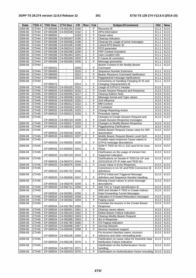
ETSI
ETSI TS 129 274 V12.6.0 (2014-10)3013GPP TS 29.274 version 12.6.0 Release 12
Date TSG # TSG Doc CT4 Doc CR Rev Cat Subject/Comment Old New 2009-06 CT#44 CP-090288 C4-091241 0190 - F Recovery IE 8.1.1 8.2.0 2009-06 CT#44 CP-090288 C4-091539 0192 1 F APN Information 8.1.1 8.2.0 2009-06 CT#44 CP-090500 - 0193 3 F Cause value 8.1.1 8.2.0 2009-06 CT#44 CP-090288 C4-091547 0195 1 F Cleanup indication 8.1.1 8.2.0 2009-06 CT#44 CP-090288 C4-091556 0196 1 F Cleanup the usage of some messages 8.1.1 8.2.0 2009-06 CT#44 CP-090288 C4-091545 0198 1 F Linked EPS Bearer ID 8.1.1 8.2.0 2009-06 CT#44 CP-090288 C4-091514 0199 1 F PCO parameter 8.1.1 8.2.0 2009-06 CT#44 CP-090288 C4-091558 0200 1 F PDP Context Activation 8.1.1 8.2.0 2009-06 CT#44 CP-090288 C4-091464 0201 1 F User Location Info 8.1.1 8.2.0 2009-06 CT#44 CP-090288 C4-091559 0202 2 F F-Cause IE correction 8.1.1 8.2.0 2009-06 CT#44 CP-090288 C4-091560 0206 1 F Message granularity 8.1.1 8.2.0 2009-06 CT#44
CP-090321 - 0209 - F Bearer Context in the Modify Bearer Command
8.1.1 8.2.0
2009-06 CT#44 CP-090493 - 0210 1 F Sequence Number Extension 8.1.1 8.2.0 2009-06 CT#44 CP-090355 - 0212 - F Bearer Resource Command clarification 8.1.1 8.2.0 2009-06 CT#44 CP-090485 - 0213 1 F Piggybacked message clarifications 8.1.1 8.2.0 2009-06 CT#44
CP-090472 - 0214 1 F Corrections on handling Charging ID IE and Charging Characteristics IE
8.1.1 8.2.0
2009-09 CT#45 CP-090533 C4-091625 0215 - F Usage of GTPv2-C Header 8.2.0 8.3.0 2009-09 CT#45 CP-090533 C4-092004 0216 1 F Create Session Request and Response 8.2.0 8.3.0 2009-09 CT#45 CP-090533 C4-092005 0217 1 F Cleanup Editors Note 8.2.0 8.3.0 2009-09 CT#45 CP-090533 C4-092008 0218 1 F Message format and Type values 8.2.0 8.3.0 2009-09 CT#45 CP-090533 C4-091630 0220 - F S16 Influence 8.2.0 8.3.0 2009-09 CT#45 CP-090533 C4-092012 0222 1 F MM Context 8.2.0 8.3.0 2009-09 CT#45 CP-090533 C4-091633 0223 - F F-Container 8.2.0 8.3.0 2009-09 CT#45 CP-090533 C4-091635 0225 - F Change Reporting Action 8.2.0 8.3.0 2009-09 CT#45 CP-090533 C4-092013 0226 1 F Procedure names 8.2.0 8.3.0 2009-09 CT#45
CP-090533 C4-092134 0228 3 F Changes to Create-Session-Request and Create-Session-Response messages
8.2.0 8.3.0
2009-09 CT#45 CP-090533 C4-092017 0229 1 F Changes to Modify-Bearer-Response 8.2.0 8.3.0 2009-09 CT#45 CP-090533 C4-092014 0232 2 F Piggybacking Clarifications 8.2.0 8.3.0 2009-09 CT#45
CP-090533 C4-092018 0236 1 F Delete Bearer Request Cause value for ISR deactivation
8.2.0 8.3.0
2009-09 CT#45 CP-090533 C4-092019 0237 2 F Modify Bearer Request Bearer Level QoS 8.2.0 8.3.0 2009-09 CT#45
CP-090533 C4-092020 0239 1 F Possible reject response Cause values in GTPv2 message descriptions
8.2.0 8.3.0
2009-09 CT#45 CP-090533 C4-092002 0241 1 F
SGW F-TEID for S1-U, S12 and S4 for User Plane
8.2.0 8.3.0
2009-09 CT#45 CP-090533 C4-092103 0243 2 F
Clarification on the usage of Version Not Supported Indication
8.2.0 8.3.0
2009-09 CT#45 CP-090533 C4-092074 0244 1 F
Clarifications on Sender-F-TEID for CP and S3/S10/S16 CP IP Addr and TEID IEs
8.2.0 8.3.0
2009-09 CT#45 CP-090533 C4-092076 0245 1 F Cause Value in Echo Response 8.2.0 8.3.0 2009-09 CT#45
CP-090533 C4-091722 0246 - F Corrections in ULI IE and PDN Connection IE definitions
8.2.0 8.3.0
2009-09 CT#45 CP-090533 C4-092656 0247 3 F
GTPv2 Initial and Triggered Message definition and Sequence Number handling
8.2.0 8.3.0
2009-09 CT#45 CP-090533 C4-092078 0249 1 F
Missing Cause values in some message descriptions
8.2.0 8.3.0
2009-09 CT#45 CP-090533 C4-092711 0250 4 F Add TAC to Target Identification IE 8.2.0 8.3.0 2009-09 CT#45
CP-090533 C4-092081 0256 1 F IMSI and Sender F-TEID in Create Indirect Data Forwarding Tunnel Messages
8.2.0 8.3.0
2009-09 CT#45 CP-090534 C4-092009 0258 1 F Indication in Forward Relocation messages 8.2.0 8.3.0 2009-09 CT#45 CP-090534 C4-092082 0259 1 F Paging cause 8.2.0 8.3.0 2009-09 CT#45
CP-090534 C4-091784 0260 - F Correlate the bearers in the Create Bearer Response
8.2.0 8.3.0
2009-09 CT#45 CP-090534 C4-092651 0261 3 F Cleanup cause values 8.2.0 8.3.0 2009-09 CT#45 CP-090534 C4-092104 0262 2 F Delete Bearer Failure Indication 8.2.0 8.3.0 2009-09 CT#45 CP-090534 C4-092083 0263 1 F Cleanup Modify Bearer Request 8.2.0 8.3.0 2009-09 CT#45 CP-090534 C4-092085 0264 2 F IEs in Response 8.2.0 8.3.0 2009-09 CT#45 CP-090534 C4-091790 0266 - F CS Paging Indication 8.2.0 8.3.0 2009-09 CT#45 CP-090534 C4-092086 0267 2 F Serving Network 8.2.0 8.3.0 2009-09 CT#45 CP-090534 C4-092636 0268 3 F Service Handover support 8.2.0 8.3.0 2009-09 CT#45
CP-090534 C4-092105 0269 3 F Fix incorrect interface name, incorrect reference and other misreading texts
8.2.0 8.3.0
2009-09 CT#45 CP-090534 C4-092106 0270 1 F
Clarification on cause value for Downlink Data Notification Failure Indication
8.2.0 8.3.0
2009-09 CT#45 CP-090534 C4-092710 0271 2 F
Clarification on the Authentication Vector handling
8.2.0 8.3.0
2009-09 CT#45 CP-090534 C4-092043 0276 1 F Clarification on Authentication Vector encoding 8.2.0 8.3.0
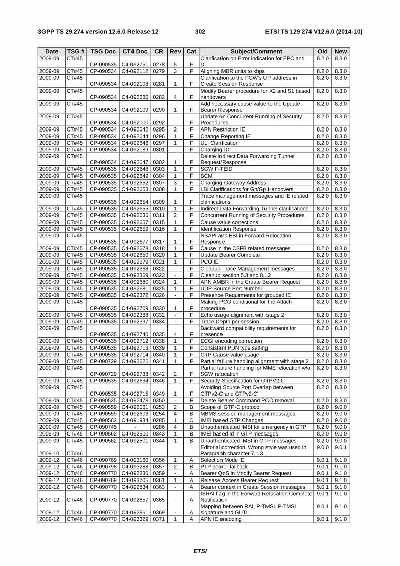
ETSI
ETSI TS 129 274 V12.6.0 (2014-10)3023GPP TS 29.274 version 12.6.0 Release 12
Date TSG # TSG Doc CT4 Doc CR Rev Cat Subject/Comment Old New 2009-09 CT#45
CP-090535 C4-092751 0278 5 F Clarification on Error indication for EPC and DT
8.2.0 8.3.0
2009-09 CT#45 CP-090534 C4-092112 0279 3 F Aligning MBR units to kbps 8.2.0 8.3.0 2009-09 CT#45
CP-090534 C4-092108 0281 1 F Clarification to the PGW's UP address in Create Session Response
8.2.0 8.3.0
2009-09 CT#45 CP-090534 C4-092686 0282 4 F
Modify Bearer procedure for X2 and S1 based handovers
8.2.0 8.3.0
2009-09 CT#45 CP-090534 C4-092109 0290 1 F
Add necessary cause value to the Update Bearer Response
8.2.0 8.3.0
2009-09 CT#45 CP-090534 C4-092000 0292 - F
Update on Concurrent Running of Security Procedures
8.2.0 8.3.0
2009-09 CT#45 CP-090534 C4-092642 0295 2 F APN Restriction IE 8.2.0 8.3.0 2009-09 CT#45 CP-090534 C4-092644 0296 1 F Change Reporting IE 8.2.0 8.3.0 2009-09 CT#45 CP-090534 C4-092646 0297 1 F ULI Clarification 8.2.0 8.3.0 2009-09 CT#45 CP-090534 C4-092189 0301 - F Charging ID 8.2.0 8.3.0 2009-09 CT#45
CP-090534 C4-092647 0302 1 F Delete Indirect Data Forwarding Tunnel Request/Response
8.2.0 8.3.0
2009-09 CT#45 CP-090535 C4-092648 0303 1 F SGW F-TEID 8.2.0 8.3.0 2009-09 CT#45 CP-090535 C4-092649 0304 1 F BCM 8.2.0 8.3.0 2009-09 CT#45 CP-090535 C4-092652 0307 3 F Charging Gateway Address 8.2.0 8.3.0 2009-09 CT#45 CP-090535 C4-092653 0308 1 F LBI Clarifications for Gn/Gp Handovers 8.2.0 8.3.0 2009-09 CT#45
CP-090535 C4-092654 0309 1 F Trace management messages and IE related clarifications
8.2.0 8.3.0
2009-09 CT#45 CP-090535 C4-092655 0310 1 F Indirect Data Forwarding Tunnel clarifications 8.2.0 8.3.0 2009-09 CT#45 CP-090535 C4-092635 0311 2 F Concurrent Running of Security Procedures 8.2.0 8.3.0 2009-09 CT#45 CP-090535 C4-092657 0315 1 F Cause value corrections 8.2.0 8.3.0 2009-09 CT#45 CP-090535 C4-092659 0316 1 F Identification Response 8.2.0 8.3.0 2009-09 CT#45
CP-090535 C4-092677 0317 1 F NSAPI and EBI in Forward Relocation Response
8.2.0 8.3.0
2009-09 CT#45 CP-090535 C4-092678 0318 1 F Cause in the CSFB related messages 8.2.0 8.3.0 2009-09 CT#45 CP-090535 C4-092650 0320 1 F Update Bearer Complete 8.2.0 8.3.0 2009-09 CT#45 CP-090535 C4-092679 0321 1 F PCO IE 8.2.0 8.3.0 2009-09 CT#45 CP-090535 C4-092368 0322 - F Cleanup Trace Management messages 8.2.0 8.3.0 2009-09 CT#45 CP-090535 C4-092369 0323 - F Cleanup section 5.3 and 8.12 8.2.0 8.3.0 2009-09 CT#45 CP-090535 C4-092680 0324 1 F APN AMBR in the Create Bearer Request 8.2.0 8.3.0 2009-09 CT#45 CP-090535 C4-092681 0325 1 F UDP Source Port Number 8.2.0 8.3.0 2009-09 CT#45 CP-090535 C4-092372 0326 - F Presence Requirments for grouped IE 8.2.0 8.3.0 2009-09 CT#45
CP-090535 C4-092709 0330 1 F Making PCO conditional for the Attach procedure
8.2.0 8.3.0
2009-09 CT#45 CP-090535 C4-092388 0332 - F Echo usage alignment with stage 2 8.2.0 8.3.0 2009-09 CT#45 CP-090535 C4-092397 0334 - F Trace Depth per session 8.2.0 8.3.0 2009-09 CT#45
CP-090535 C4-092740 0335 4 F Backward compatibility requirements for presence
8.2.0 8.3.0
2009-09 CT#45 CP-090535 C4-092712 0338 1 F ECGI encoding correction 8.2.0 8.3.0 2009-09 CT#45 CP-090535 C4-092713 0339 1 F Consistant PDN type setting 8.2.0 8.3.0 2009-09 CT#45 CP-090535 C4-092714 0340 1 F GTP Cause value usage 8.2.0 8.3.0 2009-09 CT#45 CP-090729 C4-092626 0341 1 F Partial failure handling alignment with stage 2 8.2.0 8.3.0 2009-09 CT#45
CP-090729 C4-092738 0342 2 F Partial failure handling for MME relocation w/o SGW relocation
8.2.0 8.3.0
2009-09 CT#45 CP-090535 C4-092634 0346 1 F Security Specification for GTPV2-C 8.2.0 8.3.0 2009-09 CT#45
CP-090535 C4-092715 0349 1 F Avoiding Source Port Overlap between GTPv2-C and GTPv2-C'
8.2.0 8.3.0
2009-09 CT#45 CP-090535 C4-092478 0350 - F Delete Bearer Command PCO removal 8.2.0 8.3.0 2009-09 CT#45 CP-090559 C4-092061 0253 2 B Scope of GTP-C protocol 8.2.0 9.0.0 2009-09 CT#45 CP-090559 C4-092603 0254 4 B MBMS session management messages 8.2.0 9.0.0 2009-09 CT#45 CP-090562 C4-091934 0285 1 C IMEI based GTP Changes 8.2.0 9.0.0 2009-09 CT#45 CP-090745 - 0286 4 B Unauthenticated IMSI for emergency in GTP 8.2.0 9.0.0 2009-09 CT#45 CP-090562 C4-092500 0343 1 B IMEI based Id in GTP messages 8.2.0 9.0.0 2009-09 CT#45 CP-090562 C4-092501 0344 1 B Unauthenticated IMSI in GTP messages 8.2.0 9.0.0
2009-10 CT#46 Editorial correction. Wrong style was used in Paragraph character 7.1.3.
9.0.0 9.0.1
2009-12 CT#46 CP-090769 C4-093160 0356 1 A Selection Mode IE 9.0.1 9.1.0 2009-12 CT#46 CP-090798 C4-093288 0357 2 B PTP bearer fallback 9.0.1 9.1.0 2009-12 CT#46 CP-090770 C4-092830 0359 - A Bearer QoS in Modify Bearer Request 9.0.1 9.1.0 2009-12 CT#46 CP-090769 C4-093705 0361 1 A Release Access Bearer Request 9.0.1 9.1.0 2009-12 CT#46 CP-090770 C4-092834 0363 - A Bearer context in Create Session messages 9.0.1 9.1.0
2009-12 CT#46 CP-090770 C4-092857 0365 - A ISRAI flag in the Forward Relocation Complete Notification
9.0.1 9.1.0
2009-12 CT#46 CP-090770 C4-092861 0369 - A Mapping between RAI, P-TMSI, P-TMSI signature and GUTI
9.0.1 9.1.0
2009-12 CT#46 CP-090770 C4-093329 0371 1 A APN IE encoding 9.0.1 9.1.0
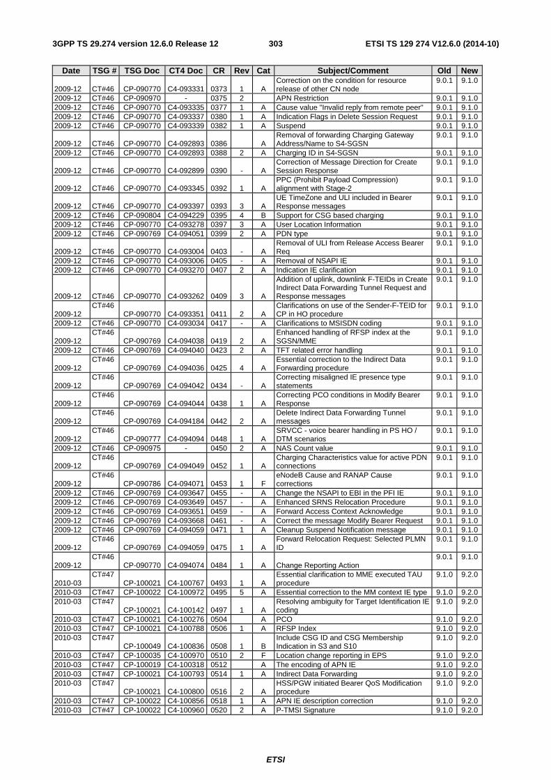
ETSI
ETSI TS 129 274 V12.6.0 (2014-10)3033GPP TS 29.274 version 12.6.0 Release 12
Date TSG # TSG Doc CT4 Doc CR Rev Cat Subject/Comment Old New
2009-12 CT#46 CP-090770 C4-093331 0373 1 A Correction on the condition for resource release of other CN node
9.0.1 9.1.0
2009-12 CT#46 CP-090970 - 0375 2 APN Restriction 9.0.1 9.1.0 2009-12 CT#46 CP-090770 C4-093335 0377 1 A Cause value "Invalid reply from remote peer" 9.0.1 9.1.0 2009-12 CT#46 CP-090770 C4-093337 0380 1 A Indication Flags in Delete Session Request 9.0.1 9.1.0 2009-12 CT#46 CP-090770 C4-093339 0382 1 A Suspend 9.0.1 9.1.0
2009-12 CT#46 CP-090770 C4-092893 0386 A Removal of forwarding Charging Gateway Address/Name to S4-SGSN
9.0.1 9.1.0
2009-12 CT#46 CP-090770 C4-092893 0388 2 A Charging ID in S4-SGSN 9.0.1 9.1.0
2009-12 CT#46 CP-090770 C4-092899 0390 - A Correction of Message Direction for Create Session Response
9.0.1 9.1.0
2009-12 CT#46 CP-090770 C4-093345 0392 1 A PPC (Prohibit Payload Compression) alignment with Stage-2
9.0.1 9.1.0
2009-12 CT#46 CP-090770 C4-093397 0393 3 A UE TimeZone and ULI included in Bearer Response messages
9.0.1 9.1.0
2009-12 CT#46 CP-090804 C4-094229 0395 4 B Support for CSG based charging 9.0.1 9.1.0 2009-12 CT#46 CP-090770 C4-093278 0397 3 A User Location Information 9.0.1 9.1.0 2009-12 CT#46 CP-090769 C4-094051 0399 2 A PDN type 9.0.1 9.1.0
2009-12 CT#46 CP-090770 C4-093004 0403 - A Removal of ULI from Release Access Bearer Req
9.0.1 9.1.0
2009-12 CT#46 CP-090770 C4-093006 0405 - A Removal of NSAPI IE 9.0.1 9.1.0 2009-12 CT#46 CP-090770 C4-093270 0407 2 A Indication IE clarification 9.0.1 9.1.0
2009-12 CT#46 CP-090770 C4-093262 0409 3 A
Addition of uplink, downlink F-TEIDs in Create Indirect Data Forwarding Tunnel Request and Response messages
9.0.1 9.1.0
2009-12 CT#46
CP-090770 C4-093351 0411 2 A Clarifications on use of the Sender-F-TEID for CP in HO procedure
9.0.1 9.1.0
2009-12 CT#46 CP-090770 C4-093034 0417 - A Clarifications to MSISDN coding 9.0.1 9.1.0
2009-12 CT#46
CP-090769 C4-094038 0419 2 A Enhanced handling of RFSP index at the SGSN/MME
9.0.1 9.1.0
2009-12 CT#46 CP-090769 C4-094040 0423 2 A TFT related error handling 9.0.1 9.1.0
2009-12 CT#46
CP-090769 C4-094036 0425 4 A Essential correction to the Indirect Data Forwarding procedure
9.0.1 9.1.0
2009-12 CT#46
CP-090769 C4-094042 0434 - A Correcting misaligned IE presence type statements
9.0.1 9.1.0
2009-12 CT#46
CP-090769 C4-094044 0438 1 A Correcting PCO conditions in Modify Bearer Response
9.0.1 9.1.0
2009-12 CT#46
CP-090769 C4-094184 0442 2 A Delete Indirect Data Forwarding Tunnel messages
9.0.1 9.1.0
2009-12 CT#46
CP-090777 C4-094094 0448 1 A SRVCC - voice bearer handling in PS HO / DTM scenarios
9.0.1 9.1.0
2009-12 CT#46 CP-090975 - 0450 2 A NAS Count value 9.0.1 9.1.0
2009-12 CT#46
CP-090769 C4-094049 0452 1 A Charging Characteristics value for active PDN connections
9.0.1 9.1.0
2009-12 CT#46
CP-090786 C4-094071 0453 1 F eNodeB Cause and RANAP Cause corrections
9.0.1 9.1.0
2009-12 CT#46 CP-090769 C4-093647 0455 - A Change the NSAPI to EBI in the PFI IE 9.0.1 9.1.0 2009-12 CT#46 CP-090769 C4-093649 0457 - A Enhanced SRNS Relocation Procedure 9.0.1 9.1.0 2009-12 CT#46 CP-090769 C4-093651 0459 - A Forward Access Context Acknowledge 9.0.1 9.1.0 2009-12 CT#46 CP-090769 C4-093668 0461 - A Correct the message Modify Bearer Request 9.0.1 9.1.0 2009-12 CT#46 CP-090769 C4-094059 0471 1 A Cleanup Suspend Notification message 9.0.1 9.1.0
2009-12 CT#46
CP-090769 C4-094059 0475 1 A Forward Relocation Request: Selected PLMN ID
9.0.1 9.1.0
2009-12 CT#46
CP-090770 C4-094074 0484 1 A Change Reporting Action 9.0.1 9.1.0
2010-03 CT#47
CP-100021 C4-100767 0493 1 A Essential clarification to MME executed TAU procedure
9.1.0 9.2.0
2010-03 CT#47 CP-100022 C4-100972 0495 5 A Essential correction to the MM context IE type 9.1.0 9.2.0 2010-03 CT#47
CP-100021 C4-100142 0497 1 A Resolving ambiguity for Target Identification IE coding
9.1.0 9.2.0
2010-03 CT#47 CP-100021 C4-100276 0504 A PCO 9.1.0 9.2.0 2010-03 CT#47 CP-100021 C4-100788 0506 1 A RFSP Index 9.1.0 9.2.0 2010-03 CT#47
CP-100049 C4-100836 0508 1 B Include CSG ID and CSG Membership Indication in S3 and S10
9.1.0 9.2.0
2010-03 CT#47 CP-100035 C4-100970 0510 2 F Location change reporting in EPS 9.1.0 9.2.0 2010-03 CT#47 CP-100019 C4-100318 0512 A The encoding of APN IE 9.1.0 9.2.0 2010-03 CT#47 CP-100021 C4-100793 0514 1 A Indirect Data Forwarding 9.1.0 9.2.0 2010-03 CT#47
CP-100021 C4-100800 0516 2 A HSS/PGW initiated Bearer QoS Modification procedure
9.1.0 9.2.0
2010-03 CT#47 CP-100022 C4-100856 0518 1 A APN IE description correction 9.1.0 9.2.0 2010-03 CT#47 CP-100022 C4-100960 0520 2 A P-TMSI Signature 9.1.0 9.2.0
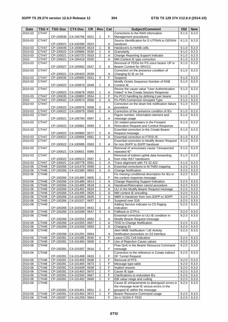
ETSI
ETSI TS 129 274 V12.6.0 (2014-10)3043GPP TS 29.274 version 12.6.0 Release 12
Date TSG # TSG Doc CT4 Doc CR Rev Cat Subject/Comment Old New 2010-03 CT#47
CP-100035 C4-100756 0521 1 F Corrections to the RAN Information Management procedures
9.1.0 9.2.0
2010-03 CT#47 CP-100021 C4-100396 0523 A
Source Identification for E-UTRAN to GERAN handover
9.1.0 9.2.0
2010-03 CT#47 CP-100049 C4-100839 0524 1 B Handovers to HeNB cells 9.1.0 9.2.0 2010-03 CT#47 CP-100022 C4-100866 0530 1 A Granularity 9.1.0 9.2.0 2010-03 CT#47 CP-100021 C4-100720 0533 2 A Change Reporting Support Indicator 9.1.0 9.2.0 2010 CT#47 CP-100021 C4-100416 0535 A MM Context IE type correction 9.1.0 9.2.0 2010-03 CT#47
CP-100027 C4-100992 0537 2 A Removal of TEIDs for PS voice bearer UP in Bearer Context for SRVCC
9.1.0 9.2.0
2010-03 CT#47 CP-100021 C4-100420 0539 A
Correction on the presence condition of Charging ID IE on S4
9.1.0 9.2.0
2010-03 CT#47 CP-100035 C4-100995 0541 3 F Suspend 9.1.0 9.2.0 2010-03 CT#47
CP-100022 C4-100876 0548 1 A Modify Octets Sequence Number of RAB Context IE
9.1.0 9.2.0
2010-03 CT#47 CP-100022 C4-100878 0550 1 A
Revive the cause value "User Authentication Failed" in the Create Session Response
9.1.0 9.2.0
2010-03 CT#47 CP-100035 C4-100883 0554 1 F Fix PCO handling by defining it per bearer 9.1.0 9.2.0 2010 CT#47 CP-100022 C4-100974 0556 2 A Fix PDN Connection Grouped Type 9.1.0 9.2.0 2010-03 CT#47
CP-100022 C4-100976 0558 2 A Correction on the down link notification failure procedure
9.1.0 9.2.0
2010-03 CT#47 CP-100022 C4-100979 0565 2 A Correction of the presence condtion of IEs 9.1.0 9.2.0 2010-03 CT#47
CP-100021 C4-100784 0567 1 A Figure number, Information element and message usage
9.1.0 9.2.0
2010-03 CT#47 CP-100022 C4-100981 0569 2 A
2G related parameters in the Forward Relocation Request and Context Response
9.1.0 9.2.0
2010-03 CT#47 CP-100022 C4-100983 0577 2 A
Essential correction to the Create Bearer Request message
9.1.0 9.2.0
2010-03 CT#47 CP-100022 C4-100906 0581 1 A Essential correction to FTEID IE 9.1.0 9.2.0 2010-03 CT#47
CP-100022 C4-100985 0583 2 A Essential correction to Modify Bearer Request for non-3GPP to 3GPP handover
9.1.0 9.2.0
2010-03 CT#47 CP-100021 C4-100601 0585 A
Removal of unncessary cause "Unexpected repeated IE"
9.1.0 9.2.0
2010-03 CT#47 CP-100022 C4-100913 0587 1 A
Removal of indirect uplink data forwarding from Inter RAT handovers
9.1.0 9.2.0
2010-03 CT#47 CP-100021 C4-100778 0591 1 A Trace alignment with TS 32.422 9.1.0 9.2.0 2010-06 CT#48 CP-100266 C4-101479 0599 1 A Essential corrections to M-TMSI mapping 9.2.0 9.3.0 2010-06 CT#48 CP-100266 C4-101580 0603 3 A Change Notification 9.2.0 9.3.0 2010-06 CT#48
CP-100266 C4-101480 0605 1 F Fix missing conditional description for IEs in the context response message
9.2.0 9.3.0
2010-06 CT#48 CP-100266 C4-101486 0614 1 A Change Reporting Support Indication 9.2.0 9.3.0 2010-06 CT#48 CP-100266 C4-101489 0618 1 A Handover/Relocation cancel procedure 9.2.0 9.3.0 2010-06 CT#48 CP-100266 C4-101491 0624 1 A ULI in the Modify Bearer Request message 9.2.0 9.3.0 2010-06 CT#48 CP-100266 C4-101495 0626 1 A MM context IE encoding 9.2.0 9.3.0 2010-06 CT#48 CP-100266 C4-101583 0635 2 A MBR in handover from non-3GPP to 3GPP 9.2.0 9.3.0 2010-06 CT#48 CP-100266 C4-101537 0637 1 F Suspend over S16 9.2.0 9.3.0 2010-06 CT#48
CP-100266 C4-101504 0642 1 A Adding Service indicator to CS Paging Indication
9.2.0 9.3.0
2010-06 CT#48 CP-100266 C4-101599 0647 3 A Fallback to GTPv1 9.2.0 9.3.0 2010-06 CT#48
CP-100266 C4-101553 0650 2 A Essential correction to ULI IE condition in Modify Bearer Request message
9.2.0 9.3.0
2010-06 CT#48 CP-100266 C4-101555 0657 1 A TEID in Change Notification 9.2.0 9.3.0 2010-06 CT#48 CP-100266 C4-101558 0659 1 A Charging ID 9.2.0 9.3.0 2010-06 CT#48
CP-100266 C4-101291 0664 A Alert MME Notification / UE Activity Notification procedure on S3 interface
9.2.0 9.3.0
2010-06 CT#48 CP-100281 C4-101585 0540 4 F Leave CSG Cell indication 9.2.0 9.3.0 2010-06 CT#48 CP-100281 C4-101484 0609 1 F Use of Rejection Cause values 9.2.0 9.3.0 2010-06 CT#48
CP-100281 C4-101597 0616 2 F Flow QoS in the Bearer Resource Command message
9.2.0 9.3.0
2010-06 CT#48 CP-100281 C4-101498 0633 1 F
Correction to the reference in Create indirect DF Tunnel Request
9.2.0 9.3.0
2010-06 CT#48 CP-100281 C4-101459 0638 1 F Removal of FFS 9.2.0 9.3.0 2010-06 CT#48 CP-100281 C4-101465 0673 1 F Message type table 9.2.0 9.3.0 2010-06 CT#48 CP-100281 C4-101609 0639 3 F Implicit resume 9.2.0 9.3.0 2010-06 CT#48 CP-100281 C4-101463 0670 1 F Cause IE type 9.2.0 9.3.0 2010-06 CT#48 CP-100281 C4-101593 0667 2 F Clarifications to redundant IEs 9.2.0 9.3.0 2010-06 CT#48 CP-100281 C4-101462 0669 1 F EBI value range and coding 9.2.0 9.3.0 2010-06 CT#48
CP-100281 C4-101461 0651 1 F
Cause IE enhacements to distinguish errors in the message level IE versus errors in the grouped IE within the message
9.2.0 9.3.0
2010-06 CT#48 CP-100281 C4-101464 0672 1 F Bearer Resource Command usage 9.2.0 9.3.0 2010-06 CT#48 CP-100287 C4-101259 0654 F Sn-U SGSN F-TEID 9.2.0 9.3.0
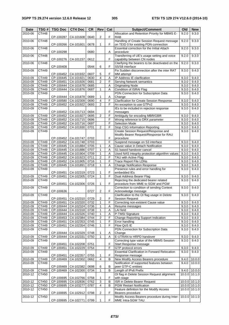
ETSI
ETSI TS 129 274 V12.6.0 (2014-10)3053GPP TS 29.274 version 12.6.0 Release 12
Date TSG # TSG Doc CT4 Doc CR Rev Cat Subject/Comment Old New 2010-06 CT#48
CP-100287 C4-101608 0640 2 F Allocation and Retention Priority for MBMS E-RAB
9.2.0 9.3.0
2010-06 CT#48 CP-100266 C4-101601 0678 1 F
Handling of Create Session Request message on TEID 0 for existing PDN connection
9.2.0 9.3.0
2010-06 CT#48 CP-100298 0680 A
Essential correction for the Initial Attach procedure
9.2.0 9.3.0
2010-06 CT#48 CP-100276 C4-101157 0612 F
Transferring of UE's usage setting and voice capability between CN nodes
9.2.0 9.3.0
2010-06 CT#48 CP-100408 0544 6 F
Clarifying the bearers to be deactivated on the S5/S8 interface
9.2.0 9.3.0
2010-09 CT#49 CP-100452 C4-101932 0607 5 F
Fix Sudden disconnection after the inter RAT MM attempt
9.3.0 9.4.0
2010-09 CT#49 CP-100445 C4-101921 0630 4 A IP Address IE clarification 9.3.0 9.4.0 2010-09 CT#49 CP-100451 C4-101926 0681 2 F Serving Network semantics 9.3.0 9.4.0 2010-09 CT#49 CP-100444 C4-101678 0685 A Originating Node 9.3.0 9.4.0 2010-09 CT#49 CP-100444 C4-101876 0687 1 A Condition of ISRAI Flag 9.3.0 9.4.0 2010-09 CT#49
CP-100444 C4-101878 0689 1 A PDN Connection for Subscription Data Change
9.3.0 9.4.0
2010-09 CT#49 CP-100580 C4-102309 0690 4 F Clarification for Create Session Response 9.3.0 9.4.0 2010-09 CT#49 CP-100452 C4-101922 0693 2 F An exception to use GTPv2 9.3.0 9.4.0 2010-09 CT#49
CP-100452 C4-101713 0694 F IEs to be included in rejection response messages
9.3.0 9.4.0
2010-09 CT#49 CP-100452 C4-101927 0695 2 F Ambiguity for encoding MBR/GBR 9.3.0 9.4.0 2010-09 CT#49 CP-100452 C4-101715 0696 F Wrong reference to DRX parameter 9.3.0 9.4.0 2010-09 CT#49 CP-100452 C4-101716 0697 F Selection Mode 9.3.0 9.4.0 2010-09 CT#49 CP-100452 C4-101930 0701 2 F Stop CSG Information Reporting 9.3.0 9.4.0 2010-09 CT#49
CP-100452 C4-101747 0702 F
Create Session Request/Response and Modify Bearer Request/Response for RAU procedure
9.3.0 9.4.0
2010-09 CT#49 CP-100452 C4-101748 0703 F Suspend message on S3 interface 9.3.0 9.4.0 2010-09 CT#49 CP-100445 C4-101884 0705 1 A Cause value in Detach Notification 9.3.0 9.4.0 2010-09 CT#49 CP-100445 C4-101886 0707 1 A S1 based handover cancel 9.3.0 9.4.0 2010-09 CT#49 CP-100445 C4-101904 0709 1 A Used NAS integrity protection algorithm values 9.3.0 9.4.0 2010-09 CT#49 CP-100452 C4-101923 0711 2 F TAU with Active Flag 9.3.0 9.4.0 2010-09 CT#49 CP-100452 C4-101905 0716 1 F Trace Report File LDNs 9.3.0 9.4.0 2010-09 CT#49 CP-100445 C4-101891 0718 1 A Change Notification Response 9.3.0 9.4.0 2010-09 CT#49
CP-100451 C4-102319 0723 1 F Presence rules and error handling for embedded IEs
9.3.0 9.4.0
2010-09 CT#49 CP-100451 C4-102305 0724 1 F Dual Address Bearer Flag 9.3.0 9.4.0 2010-09 CT#49
CP-100451 C4-102306 0726 1 F Rejecting the dedicated bearer related procedure from MME to SGW and PGW
9.3.0 9.4.0
2010-09 CT#49 CP-100636 - 0727 2 F
Correction to condition of sending Context Acknowledge message
9.3.0 9.4.0
2010-09 CT#49 CP-100451 C4-102310 0729 2 F
Clarification to the OI flag usage in Delete Session Request
9.3.0 9.4.0
2010-09 CT#49 CP-100451 C4-102320 0732 1 F Correcting non-existent Cause value 9.3.0 9.4.0 2010-09 CT#49 CP-100444 C4-102324 0736 1 A Resume messages 9.3.0 9.4.0 2010-09 CT#49 CP-100444 C4-102318 0738 1 A LAI field 9.3.0 9.4.0 2010-09 CT#49 CP-100444 C4-102326 0740 1 A P-TMSI Signature 9.3.0 9.4.0 2010-09 CT#49 CP-100453 C4-102384 0744 2 F Change Reporting Support Indication 9.3.0 9.4.0 2010-09 CT#49 CP-100451 C4-102353 0745 1 F Error handling 9.3.0 9.4.0 2010-09 CT#49 CP-100451 C4-102354 0746 1 F Flow QoS IE 9.3.0 9.4.0 2010-09 CT#49
CP-100444 C4-102329 0748 1 A PDN Connection for Subscription Data Change
9.3.0 9.4.0
2010-09 CT#49 CP-100444 C4-102331 0750 1 A E-UTRAN to HRPD handover 9.3.0 9.4.0 2010-09 CT#49
CP-100451 C4-102208 0751 F Correcting type value of the MBMS Session Start Response message
9.3.0 9.4.0
2010-09 CT#49 CP-100451 C4-102229 0754 F GTP protocol errors 9.3.0 9.4.0 2010-09 CT#49
CP-100451 C4-102357 0755 1 F Essential Clarification in Forward Relocation Response message
9.3.0 9.4.0
2010-09 CT#49 CP-100469 C4-102302 0662 4 B New Modify Access Bearers procedure 9.4.0 10.0.0 2010-09 CT#49
CP-100469 C4-102382 0698 6 B Notification of supported features between peer GTP-C entities
9.4.0 10.0.0
2010-09 CT#49 CP-100469 C4-102300 0734 1 B Length of IPv6 Prefix 9.4.0 10.0.0 2010-12 CT#50
CP-100695 C4-102766 0758 1 F OI flag in Delete Session Request alignment with stage
10.0.0 10.1.0
2010-12 CT#50 CP-100695 C4-102836 0762 3 B ISR in Delete Bearer Request 10.0.0 10.1.0 2010-12 CT#50 CP-100695 C4-103277 0787 4 B PGW Restart Notification 10.0.0 10.1.0 2010-12 CT#50
CP-100695 C4-102912 0798 2 F Feature definition for the Modify Access Bearers procedure
10.0.0 10.1.0
2010-12 CT#50 CP-100695 C4-102771 0799 1 F
Modify Access Bearers procedure during Inter-MME Intra-SGW TAU
10.0.0 10.1.0
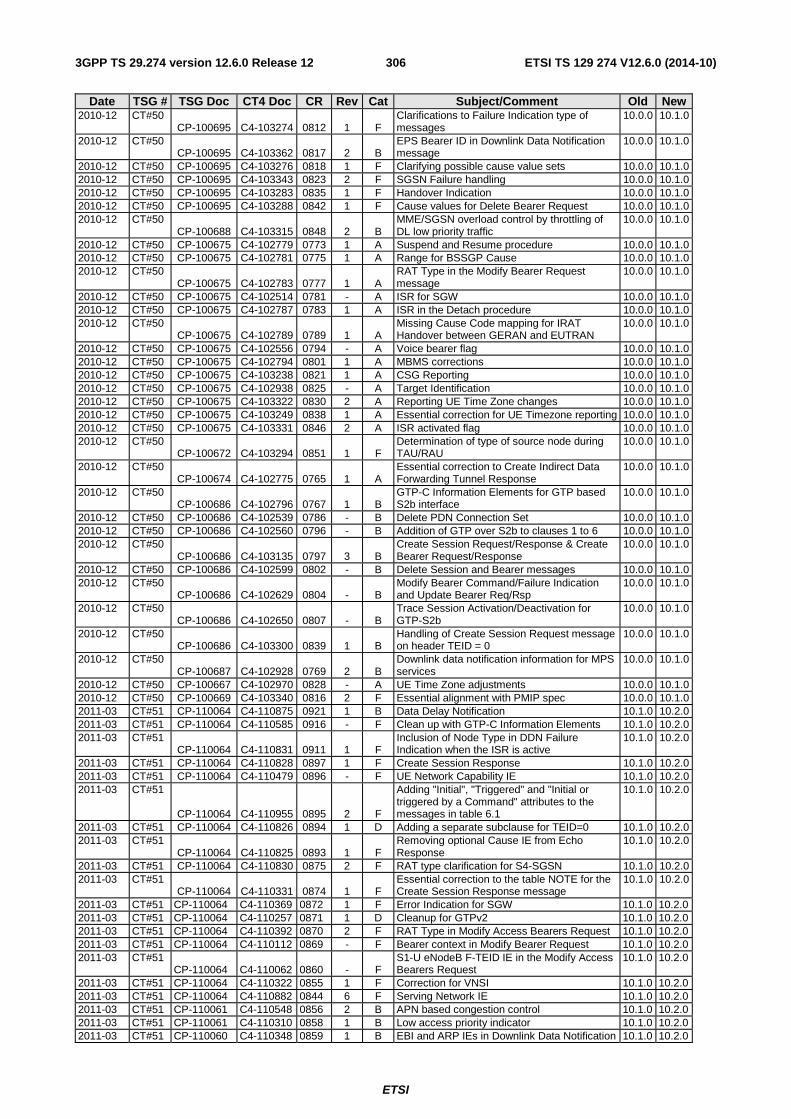
ETSI
ETSI TS 129 274 V12.6.0 (2014-10)3063GPP TS 29.274 version 12.6.0 Release 12
Date TSG # TSG Doc CT4 Doc CR Rev Cat Subject/Comment Old New 2010-12 CT#50
CP-100695 C4-103274 0812 1 F Clarifications to Failure Indication type of messages
10.0.0 10.1.0
2010-12 CT#50 CP-100695 C4-103362 0817 2 B
EPS Bearer ID in Downlink Data Notification message
10.0.0 10.1.0
2010-12 CT#50 CP-100695 C4-103276 0818 1 F Clarifying possible cause value sets 10.0.0 10.1.0 2010-12 CT#50 CP-100695 C4-103343 0823 2 F SGSN Failure handling 10.0.0 10.1.0 2010-12 CT#50 CP-100695 C4-103283 0835 1 F Handover Indication 10.0.0 10.1.0 2010-12 CT#50 CP-100695 C4-103288 0842 1 F Cause values for Delete Bearer Request 10.0.0 10.1.0 2010-12 CT#50
CP-100688 C4-103315 0848 2 B MME/SGSN overload control by throttling of DL low priority traffic
10.0.0 10.1.0
2010-12 CT#50 CP-100675 C4-102779 0773 1 A Suspend and Resume procedure 10.0.0 10.1.0 2010-12 CT#50 CP-100675 C4-102781 0775 1 A Range for BSSGP Cause 10.0.0 10.1.0 2010-12 CT#50
CP-100675 C4-102783 0777 1 A RAT Type in the Modify Bearer Request message
10.0.0 10.1.0
2010-12 CT#50 CP-100675 C4-102514 0781 - A ISR for SGW 10.0.0 10.1.0 2010-12 CT#50 CP-100675 C4-102787 0783 1 A ISR in the Detach procedure 10.0.0 10.1.0 2010-12 CT#50
CP-100675 C4-102789 0789 1 A Missing Cause Code mapping for IRAT Handover between GERAN and EUTRAN
10.0.0 10.1.0
2010-12 CT#50 CP-100675 C4-102556 0794 - A Voice bearer flag 10.0.0 10.1.0 2010-12 CT#50 CP-100675 C4-102794 0801 1 A MBMS corrections 10.0.0 10.1.0 2010-12 CT#50 CP-100675 C4-103238 0821 1 A CSG Reporting 10.0.0 10.1.0 2010-12 CT#50 CP-100675 C4-102938 0825 - A Target Identification 10.0.0 10.1.0 2010-12 CT#50 CP-100675 C4-103322 0830 2 A Reporting UE Time Zone changes 10.0.0 10.1.0 2010-12 CT#50 CP-100675 C4-103249 0838 1 A Essential correction for UE Timezone reporting 10.0.0 10.1.0 2010-12 CT#50 CP-100675 C4-103331 0846 2 A ISR activated flag 10.0.0 10.1.0 2010-12 CT#50
CP-100672 C4-103294 0851 1 F Determination of type of source node during TAU/RAU
10.0.0 10.1.0
2010-12 CT#50 CP-100674 C4-102775 0765 1 A
Essential correction to Create Indirect Data Forwarding Tunnel Response
10.0.0 10.1.0
2010-12 CT#50 CP-100686 C4-102796 0767 1 B
GTP-C Information Elements for GTP based S2b interface
10.0.0 10.1.0
2010-12 CT#50 CP-100686 C4-102539 0786 - B Delete PDN Connection Set 10.0.0 10.1.0 2010-12 CT#50 CP-100686 C4-102560 0796 - B Addition of GTP over S2b to clauses 1 to 6 10.0.0 10.1.0 2010-12 CT#50
CP-100686 C4-103135 0797 3 B Create Session Request/Response & Create Bearer Request/Response
10.0.0 10.1.0
2010-12 CT#50 CP-100686 C4-102599 0802 - B Delete Session and Bearer messages 10.0.0 10.1.0 2010-12 CT#50
CP-100686 C4-102629 0804 - B Modify Bearer Command/Failure Indication and Update Bearer Req/Rsp
10.0.0 10.1.0
2010-12 CT#50 CP-100686 C4-102650 0807 - B
Trace Session Activation/Deactivation for GTP-S2b
10.0.0 10.1.0
2010-12 CT#50 CP-100686 C4-103300 0839 1 B
Handling of Create Session Request message on header TEID = 0
10.0.0 10.1.0
2010-12 CT#50 CP-100687 C4-102928 0769 2 B
Downlink data notification information for MPS services
10.0.0 10.1.0
2010-12 CT#50 CP-100667 C4-102970 0828 - A UE Time Zone adjustments 10.0.0 10.1.0 2010-12 CT#50 CP-100669 C4-103340 0816 2 F Essential alignment with PMIP spec 10.0.0 10.1.0 2011-03 CT#51 CP-110064 C4-110875 0921 1 B Data Delay Notification 10.1.0 10.2.0 2011-03 CT#51 CP-110064 C4-110585 0916 - F Clean up with GTP-C Information Elements 10.1.0 10.2.0 2011-03 CT#51
CP-110064 C4-110831 0911 1 F Inclusion of Node Type in DDN Failure Indication when the ISR is active
10.1.0 10.2.0
2011-03 CT#51 CP-110064 C4-110828 0897 1 F Create Session Response 10.1.0 10.2.0 2011-03 CT#51 CP-110064 C4-110479 0896 - F UE Network Capability IE 10.1.0 10.2.0 2011-03 CT#51
CP-110064 C4-110955 0895 2 F
Adding "Initial", "Triggered" and "Initial or triggered by a Command" attributes to the messages in table 6.1
10.1.0 10.2.0
2011-03 CT#51 CP-110064 C4-110826 0894 1 D Adding a separate subclause for TEID=0 10.1.0 10.2.0 2011-03 CT#51
CP-110064 C4-110825 0893 1 F Removing optional Cause IE from Echo Response
10.1.0 10.2.0
2011-03 CT#51 CP-110064 C4-110830 0875 2 F RAT type clarification for S4-SGSN 10.1.0 10.2.0 2011-03 CT#51
CP-110064 C4-110331 0874 1 F Essential correction to the table NOTE for the Create Session Response message
10.1.0 10.2.0
2011-03 CT#51 CP-110064 C4-110369 0872 1 F Error Indication for SGW 10.1.0 10.2.0 2011-03 CT#51 CP-110064 C4-110257 0871 1 D Cleanup for GTPv2 10.1.0 10.2.0 2011-03 CT#51 CP-110064 C4-110392 0870 2 F RAT Type in Modify Access Bearers Request 10.1.0 10.2.0 2011-03 CT#51 CP-110064 C4-110112 0869 - F Bearer context in Modify Bearer Request 10.1.0 10.2.0 2011-03 CT#51
CP-110064 C4-110062 0860 - F S1-U eNodeB F-TEID IE in the Modify Access Bearers Request
10.1.0 10.2.0
2011-03 CT#51 CP-110064 C4-110322 0855 1 F Correction for VNSI 10.1.0 10.2.0 2011-03 CT#51 CP-110064 C4-110882 0844 6 F Serving Network IE 10.1.0 10.2.0 2011-03 CT#51 CP-110061 C4-110548 0856 2 B APN based congestion control 10.1.0 10.2.0 2011-03 CT#51 CP-110061 C4-110310 0858 1 B Low access priority indicator 10.1.0 10.2.0 2011-03 CT#51 CP-110060 C4-110348 0859 1 B EBI and ARP IEs in Downlink Data Notification 10.1.0 10.2.0
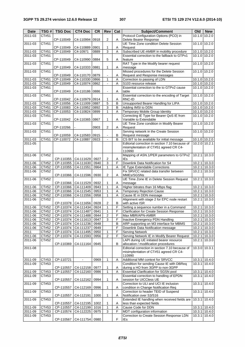
ETSI
ETSI TS 129 274 V12.6.0 (2014-10)3073GPP TS 29.274 version 12.6.0 Release 12
Date TSG # TSG Doc CT4 Doc CR Rev Cat Subject/Comment Old New 2011-03 CT#51
CP-110049 C4-110994 0918 2 A Protocol Configuration Options (PCO) in Delete Bearer Response
10.1.0 10.2.0
2011-03 CT#51 CP-110049 C4-110889 0901 1 A
UE Time Zone condition Delete Session Request
10.1.0 10.2.0
2011-03 CT#51 CP-110049 C4-10971 0889 3 A Subscribed UE-AMBR in mobility procedure 10.1.0 10.2.0 2011-03 CT#51
CP-110049 C4-110990 0884 5 A Essential correction to the fallback to GTPv1 feature
10.1.0 10.2.0
2011-03 CT#51 CP-110049 C4-110333 0881 1 A
RAT Type in the Modify bearer request message
10.1.0 10.2.0
2011-03 CT#51 CP-110049 C4-110170 0879 - A
Missed procedures for the Delete Session Request and Response messages
10.1.0 10.2.0
2011-03 CT#51 CP-110049 C4-110330 0866 1 A Correction to passing of LDN 10.1.0 10.2.0 2011-03 CT#51 CP-110049 C4-110074 0862 - A S103 resource release 10.1.0 10.2.0 2011-03 CT#51
CP-110049 C4-110186 0886 - A Essential correction to the to GTPv2 cause table
10.1.0 10.2.0
2011-03 CT#51 CP-110042 C4-110979 0914 1 A
Essential correction to the encoding of Target RNC-ID
10.1.0 10.2.0
2011-03 CT#51 CP-110056 C4-111009 0887 5 B Unsupported Bearer Handling for LIPA 10.1.0 10.2.0 2011-03 CT#51 CP-110083 C4-110952 0892 3 B Adding IMSI to DDN 10.1.0 10.2.0 2011-03 CT#51 CP-110053 C4-110824 0899 1 A Temporary Mobile Group Identity 10.1.0 10.2.0 2011-03 CT#51
CP-110042 C4-110365 0867 1 A Correcting IE Type for Bearer QoS IE from Variable to Extendable
10.1.0 10.2.0
2011-03 CT#51 CP-110266 - 0903 2 A
UE Time Zone condition in Modify Bearer Request
10.1.0 10.2.0
2011-03 CT#51 CP-110059 C4-110583 0915 - B
Serving network in the Create Session Request message
10.1.0 10.2.0
2011-03 CT#51 CP-110072 C4-110887 0923 - B CS BIT to be available for initial message 10.1.0 10.2.0 2011-05
Editorial correction in section 7.10 because of misimplentation of CT#51 agreed CR C4-110990
10.2.0 10.2.1
2011-06 CT#52 CP-110355 C4-111629 0927 2 A
Mapping of ASN.1/PER parameters to GTPv2 IEs
10.2.1 10.3.0
2011-06 CT#52 CP-110355 C4-111630 0940 3 F Downlink Data Notification for S4 10.2.1 10.3.0 2011-06 CT#52 CP-110355 C4-111551 0964 1 A IE Type Extendable Corrections 10.2.1 10.3.0 2011-06 CT#52
CP-110366 C4-111596 0930 2 A Fix SRVCC related data transfer between MMEs/SGSNs
10.2.1 10.3.0
2011-06 CT#52 CP-110366 C4-111529 0932 1 A
UE Time Zone IE in Delete Session Request message
10.2.1 10.3.0
2011-06 CT#52 CP-110366 C4-111409 0943 1 A Higher bitrates than 16 Mbps flag 10.2.1 10.3.0 2011-06 CT#52 CP-110366 C4-111545 0953 1 A Temporary Rejection Cause 10.2.1 10.3.0 2011-06 CT#52 CP-110366 C4-111556 0958 1 A Cause IE in DDN message 10.2.1 10.3.0 2011-06 CT#52
CP-110378 C4-111656 0928 2 B Alignment with stage 2 for EPC node restart with active ISR
10.2.1 10.3.0
2011-06 CT#52 CP-110374 C4-111434 0924 1 F Setting a sequence number in a Command 10.2.1 10.3.0 2011-06 CT#52 CP-110374 C4-111487 0941 1 F Clarification for Create Session Response 10.2.1 10.3.0 2011-06 CT#52 CP-110374 C4-111488 0944 2 F Max MBR/APN-AMBR 10.2.1 10.3.0 2011-06 CT#52 CP-110374 C4-111613 0947 3 F Inactive Emergency PDN Handling 10.2.1 10.3.0 2011-06 CT#52 CP-110374 C4-111236 0948 B ARP supporting on M3 interface for MBMS 10.2.1 10.3.0 2011-06 CT#52 CP-110374 C4-111237 0949 F Downlink Data Notification message 10.2.1 10.3.0 2011 CT#52 CP-110374 C4-111495 0950 1 F Serving Network 10.2.1 10.3.0 2011-06 CT#52 CP-110374 C4-111593 0956 2 F Serving Network IE in Modify Bearer Request 10.2.1 10.3.0 2011-06 CT#52
CP-110369 C4-111164 0945 B LAPI during UE initiated bearer resource allocation / modification procedures
10.2.1 10.3.0
2011-08
Editorial correction in section 7.10 because of misimplentation of CT#51 agreed CR C4-110990
10.3.0 10.3.1
2011-09 CT#53 CP-110721 - 0969 1 A Additional MM context for SRVCC 10.3.1 10.4.0 2011-09 CT#53
CP-110557 C4-112158 0977 1 A Condition for sending Cause IE with DBReq during a HO from 3GPP to non-3GPP
10.3.1 10.4.0
2011-09 CT#53 CP-110557 C4-112160 0986 1 A Essential Clarification for SGSN pool 10.3.1 10.4.0 2011-09 CT#53
CP-110557 C4-112162 0994 1 A Essential correction to handling of EPDN session for UICCless UE
10.3.1 10.4.0
2011-09 CT#53 CP-110557 C4-112169 0996 1 A
Correction to ULI and UCI IE inclusion condition in Change Notification Req
10.3.1 10.4.0
2011-09 CT#53 CP-110557 C4-112191 1000 1 A
Correction to header TEID of Suspend Notification over S3/S16
10.3.1 10.4.0
2011-09 CT#53 CP-110557 C4-112195 1002 1 A
Extended IE handling when received fields are less than expected fields
10.3.1 10.4.0
2011-09 CT#53 CP-110557 C4-112199 1016 1 A Cause Code for DDN 10.3.1 10.4.0 2011-09 CT#53 CP-110574 C4-112225 0975 3 F MDT configuration information 10.3.1 10.4.0 2011-09 CT#53
CP-110567 C4-111754 0980 F Correction to Create Session Response LDN IEs
10.3.1 10.4.0
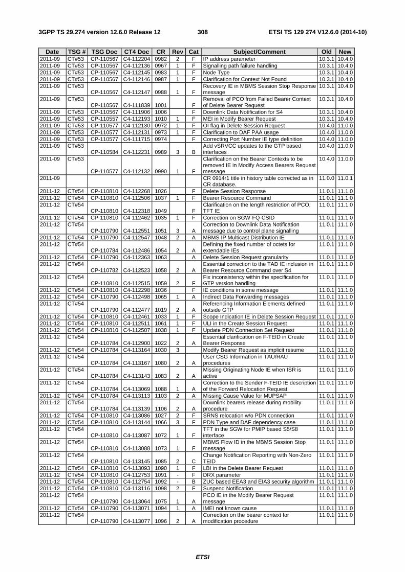
ETSI
ETSI TS 129 274 V12.6.0 (2014-10)3083GPP TS 29.274 version 12.6.0 Release 12
Date TSG # TSG Doc CT4 Doc CR Rev Cat Subject/Comment Old New 2011-09 CT#53 CP-110567 C4-112204 0982 2 F IP address parameter 10.3.1 10.4.0 2011-09 CT#53 CP-110567 C4-112136 0967 1 F Signalling path failure handling 10.3.1 10.4.0 2011-09 CT#53 CP-110567 C4-112145 0983 1 F Node Type 10.3.1 10.4.0 2011-09 CT#53 CP-110567 C4-112146 0987 1 F Clarification for Context Not Found 10.3.1 10.4.0 2011-09 CT#53
CP-110567 C4-112147 0988 1 F Recovery IE in MBMS Session Stop Response message
10.3.1 10.4.0
2011-09 CT#53 CP-110567 C4-111839 1001 F
Removal of PCO from Failed Bearer Context of Delete Bearer Request
10.3.1 10.4.0
2011-09 CT#53 CP-110567 C4-111906 1006 F Downlink Data Notification for S4 10.3.1 10.4.0 2011-09 CT#53 CP-110557 C4-112193 1010 1 F MEI in Modify Bearer Request 10.3.1 10.4.0 2011-09 CT#53 CP-110577 C4-112130 0972 1 F OI flag in Delete Session Request 10.4.0 11.0.0 2011-09 CT#53 CP-110577 C4-112131 0973 1 F Clarification to DAF PAA usage 10.4.0 11.0.0 2011-09 CT#53 CP-110577 C4-111715 0974 F Correcting Port Number IE type definition 10.4.0 11.0.0 2011-09 CT#53
CP-110584 C4-112231 0989 3 B Add vSRVCC updates to the GTP based interfaces
10.4.0 11.0.0
2011-09 CT#53
CP-110577 C4-112132 0990 1 F
Clarification on the Bearer Contexts to be removed IE in Modify Access Bearers Request message
10.4.0 11.0.0
2011-09
CR 0914r1 title in history table corrected as in CR database.
11.0.0 11.0.1
2011-12 CT#54 CP-110810 C4-112268 1026 F Delete Session Response 11.0.1 11.1.0 2011-12 CT#54 CP-110810 C4-112506 1037 1 F Bearer Resource Command 11.0.1 11.1.0 2011-12 CT#54
CP-110810 C4-112318 1049 F Clarification on the length restriction of PCO, TFT IE
11.0.1 11.1.0
2011-12 CT#54 CP-110810 C4-112462 1035 1 F Correction on SGW-FQ-CSID 11.0.1 11.1.0 2011-12 CT#54
CP-110790 C4-112551 1051 3 A Correction to Downlink Data Notification message due to control plane signalling
11.0.1 11.1.0
2011-12 CT#54 CP-110790 C4-112547 1048 2 A MBMS IP Multicast Distribution IE 11.0.1 11.1.0 2011-12 CT#54
CP-110784 C4-112486 1054 2 A Defining the fixed number of octets for extendable IEs
11.0.1 11.1.0
2011-12 CT#54 CP-110790 C4-112363 1063 A Delete Session Request granularity 11.0.1 11.1.0 2011-12 CT#54
CP-110782 C4-112523 1058 2 A Essential correction to the TAD IE inclusion in Bearer Resource Command over S4
11.0.1 11.1.0
2011-12 CT#54 CP-110810 C4-112515 1059 2 F
Fix inconsistency within the specification for GTP version handling
11.0.1 11.1.0
2011-12 CT#54 CP-110810 C4-112298 1036 F IE conditions in some message 11.0.1 11.1.0 2011-12 CT#54 CP-110790 C4-112498 1065 1 A Indirect Data Forwarding messages 11.0.1 11.1.0 2011-12 CT#54
CP-110790 C4-112477 1019 2 A Referencing Information Elements defined outside GTP
11.0.1 11.1.0
2011-12 CT#54 CP-110810 C4-112461 1033 1 F Scope Indication IE in Delete Session Request 11.0.1 11.1.0 2011-12 CT#54 CP-110810 C4-112511 1061 1 F ULI in the Create Session Request 11.0.1 11.1.0 2011-12 CT#54 CP-110810 C4-112507 1038 1 F Update PDN Connection Set Request 11.0.1 11.1.0 2011-12 CT#54
CP-110784 C4-112900 1022 2 A Essential clarification on F-TEID in Create Bearer Response
11.0.1 11.1.0
2011-12 CT#54 CP-110784 C4-113164 1030 3 Modify Bearer Request as implicit resume 11.0.1 11.1.0 2011-12 CT#54
CP-110784 C4-113167 1080 2 A User CSG Information in TAU/RAU procedures
11.0.1 11.1.0
2011-12 CT#54 CP-110784 C4-113143 1083 2 A
Missing Originating Node IE when ISR is active
11.0.1 11.1.0
2011-12 CT#54 CP-110784 C4-113069 1088 1 A
Correction to the Sender F-TEID IE description of the Forward Relocation Request
11.0.1 11.1.0
2011-12 CT#54 CP-110784 C4-113113 1103 2 A Missing Cause Value for MUPSAP 11.0.1 11.1.0 2011-12 CT#54
CP-110784 C4-113139 1106 2 A Downlink bearers release during mobility procedure
11.0.1 11.1.0
2011-12 CT#54 CP-110810 C4-113086 1027 2 F SRNS relocation w/o PDN connection 11.0.1 11.1.0 2011-12 CT#54 CP-110810 C4-113144 1066 3 F PDN Type and DAF dependency case 11.0.1 11.1.0 2011-12 CT#54
CP-110810 C4-113087 1072 1 F TFT in the SGW for PMIP based S5/S8 interface
11.0.1 11.1.0
2011-12 CT#54 CP-110810 C4-113088 1073 1 F
MBMS Flow ID in the MBMS Session Stop message
11.0.1 11.1.0
2011-12 CT#54 CP-110810 C4-113145 1085 2 C
Change Notification Reporting with Non-Zero TEID
11.0.1 11.1.0
2011-12 CT#54 CP-110810 C4-113093 1090 1 F LBI in the Delete Bearer Request 11.0.1 11.1.0 2011-12 CT#54 CP-110810 C4-112753 1091 - F DRX parameter 11.0.1 11.1.0 2011-12 CT#54 CP-110810 C4-112754 1092 - B ZUC based EEA3 and EIA3 security algorithm 11.0.1 11.1.0 2011-12 CT#54 CP-110810 C4-113116 1098 2 F Suspend Notification 11.0.1 11.1.0 2011-12 CT#54
CP-110790 C4-113064 1075 1 A PCO IE in the Modify Bearer Request message
11.0.1 11.1.0
2011-12 CT#54 CP-110790 C4-113071 1094 1 A IMEI not known cause 11.0.1 11.1.0 2011-12 CT#54
CP-110790 C4-113077 1096 2 A Correction on the bearer context for modification procedure
11.0.1 11.1.0
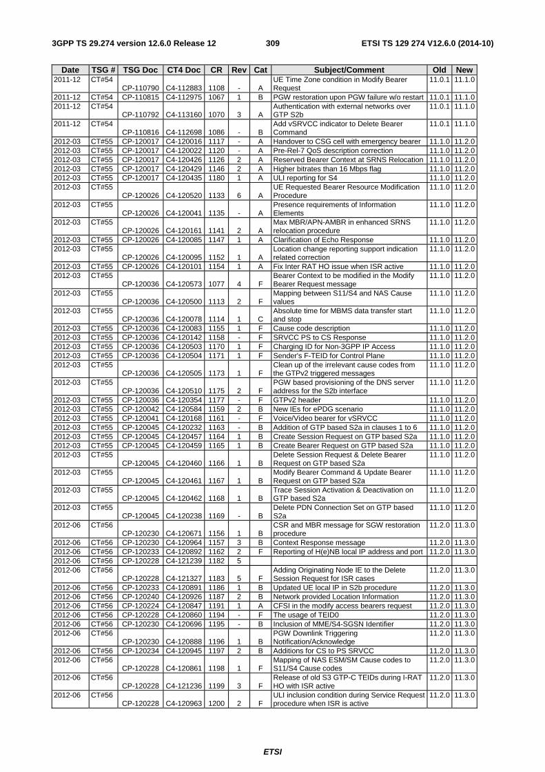
ETSI
ETSI TS 129 274 V12.6.0 (2014-10)3093GPP TS 29.274 version 12.6.0 Release 12
Date TSG # TSG Doc CT4 Doc CR Rev Cat Subject/Comment Old New 2011-12 CT#54
CP-110790 C4-112883 1108 - A UE Time Zone condition in Modify Bearer Request
11.0.1 11.1.0
2011-12 CT#54 CP-110815 C4-112975 1067 1 B PGW restoration upon PGW failure w/o restart 11.0.1 11.1.0 2011-12 CT#54
CP-110792 C4-113160 1070 3 A Authentication with external networks over GTP S2b
11.0.1 11.1.0
2011-12 CT#54 CP-110816 C4-112698 1086 - B
Add vSRVCC indicator to Delete Bearer Command
11.0.1 11.1.0
2012-03 CT#55 CP-120017 C4-120016 1117 - A Handover to CSG cell with emergency bearer 11.1.0 11.2.0 2012-03 CT#55 CP-120017 C4-120022 1120 - A Pre-Rel-7 QoS description correction 11.1.0 11.2.0 2012-03 CT#55 CP-120017 C4-120426 1126 2 A Reserved Bearer Context at SRNS Relocation 11.1.0 11.2.0 2012-03 CT#55 CP-120017 C4-120429 1146 2 A Higher bitrates than 16 Mbps flag 11.1.0 11.2.0 2012-03 CT#55 CP-120017 C4-120435 1180 1 A ULI reporting for S4 11.1.0 11.2.0 2012-03 CT#55
CP-120026 C4-120520 1133 6 A UE Requested Bearer Resource Modification Procedure
11.1.0 11.2.0
2012-03 CT#55 CP-120026 C4-120041 1135 - A
Presence requirements of Information Elements
11.1.0 11.2.0
2012-03 CT#55 CP-120026 C4-120161 1141 2 A
Max MBR/APN-AMBR in enhanced SRNS relocation procedure
11.1.0 11.2.0
2012-03 CT#55 CP-120026 C4-120085 1147 1 A Clarification of Echo Response 11.1.0 11.2.0 2012-03 CT#55
CP-120026 C4-120095 1152 1 A Location change reporting support indication related correction
11.1.0 11.2.0
2012-03 CT#55 CP-120026 C4-120101 1154 1 A Fix Inter RAT HO issue when ISR active 11.1.0 11.2.0 2012-03 CT#55
CP-120036 C4-120573 1077 4 F Bearer Context to be modified in the Modify Bearer Request message
11.1.0 11.2.0
2012-03 CT#55 CP-120036 C4-120500 1113 2 F
Mapping between S11/S4 and NAS Cause values
11.1.0 11.2.0
2012-03 CT#55 CP-120036 C4-120078 1114 1 C
Absolute time for MBMS data transfer start and stop
11.1.0 11.2.0
2012-03 CT#55 CP-120036 C4-120083 1155 1 F Cause code description 11.1.0 11.2.0 2012-03 CT#55 CP-120036 C4-120142 1158 - F SRVCC PS to CS Response 11.1.0 11.2.0 2012-03 CT#55 CP-120036 C4-120503 1170 1 F Charging ID for Non-3GPP IP Access 11.1.0 11.2.0 2012-03 CT#55 CP-120036 C4-120504 1171 1 F Sender's F-TEID for Control Plane 11.1.0 11.2.0 2012-03 CT#55
CP-120036 C4-120505 1173 1 F Clean up of the irrelevant cause codes from the GTPv2 triggered messages
11.1.0 11.2.0
2012-03 CT#55 CP-120036 C4-120510 1175 2 F
PGW based provisioning of the DNS server address for the S2b interface
11.1.0 11.2.0
2012-03 CT#55 CP-120036 C4-120354 1177 - F GTPv2 header 11.1.0 11.2.0 2012-03 CT#55 CP-120042 C4-120584 1159 2 B New IEs for ePDG scenario 11.1.0 11.2.0 2012-03 CT#55 CP-120041 C4-120168 1161 - F Voice/Video bearer for vSRVCC 11.1.0 11.2.0 2012-03 CT#55 CP-120045 C4-120232 1163 - B Addition of GTP based S2a in clauses 1 to 6 11.1.0 11.2.0 2012-03 CT#55 CP-120045 C4-120457 1164 1 B Create Session Request on GTP based S2a 11.1.0 11.2.0 2012-03 CT#55 CP-120045 C4-120459 1165 1 B Create Bearer Request on GTP based S2a 11.1.0 11.2.0 2012-03 CT#55
CP-120045 C4-120460 1166 1 B Delete Session Request & Delete Bearer Request on GTP based S2a
11.1.0 11.2.0
2012-03 CT#55 CP-120045 C4-120461 1167 1 B
Modify Bearer Command & Update Bearer Request on GTP based S2a
11.1.0 11.2.0
2012-03 CT#55 CP-120045 C4-120462 1168 1 B
Trace Session Activation & Deactivation on GTP based S2a
11.1.0 11.2.0
2012-03 CT#55 CP-120045 C4-120238 1169 - B
Delete PDN Connection Set on GTP based S2a
11.1.0 11.2.0
2012-06 CT#56 CP-120230 C4-120671 1156 1 B
CSR and MBR message for SGW restoration procedure
11.2.0 11.3.0
2012-06 CT#56 CP-120230 C4-120964 1157 3 B Context Response message 11.2.0 11.3.0 2012-06 CT#56 CP-120233 C4-120892 1162 2 F Reporting of H(e)NB local IP address and port 11.2.0 11.3.0 2012-06 CT#56 CP-120228 C4-121239 1182 5 2012-06 CT#56
CP-120228 C4-121327 1183 5 F Adding Originating Node IE to the Delete Session Request for ISR cases
11.2.0 11.3.0
2012-06 CT#56 CP-120233 C4-120891 1186 1 B Updated UE local IP in S2b procedure 11.2.0 11.3.0 2012-06 CT#56 CP-120240 C4-120926 1187 2 B Network provided Location Information 11.2.0 11.3.0 2012-06 CT#56 CP-120224 C4-120847 1191 1 A CFSI in the modify access bearers request 11.2.0 11.3.0 2012-06 CT#56 CP-120228 C4-120860 1194 - F The usage of TEID0 11.2.0 11.3.0 2012-06 CT#56 CP-120230 C4-120696 1195 - B Inclusion of MME/S4-SGSN Identifier 11.2.0 11.3.0 2012-06 CT#56
CP-120230 C4-120888 1196 1 B PGW Downlink Triggering Notification/Acknowledge
11.2.0 11.3.0
2012-06 CT#56 CP-120234 C4-120945 1197 2 B Additions for CS to PS SRVCC 11.2.0 11.3.0 2012-06 CT#56
CP-120228 C4-120861 1198 1 F Mapping of NAS ESM/SM Cause codes to S11/S4 Cause codes
11.2.0 11.3.0
2012-06 CT#56 CP-120228 C4-121236 1199 3 F
Release of old S3 GTP-C TEIDs during I-RAT HO with ISR active
11.2.0 11.3.0
2012-06 CT#56 CP-120228 C4-120963 1200 2 F
ULI inclusion condition during Service Request procedure when ISR is active
11.2.0 11.3.0
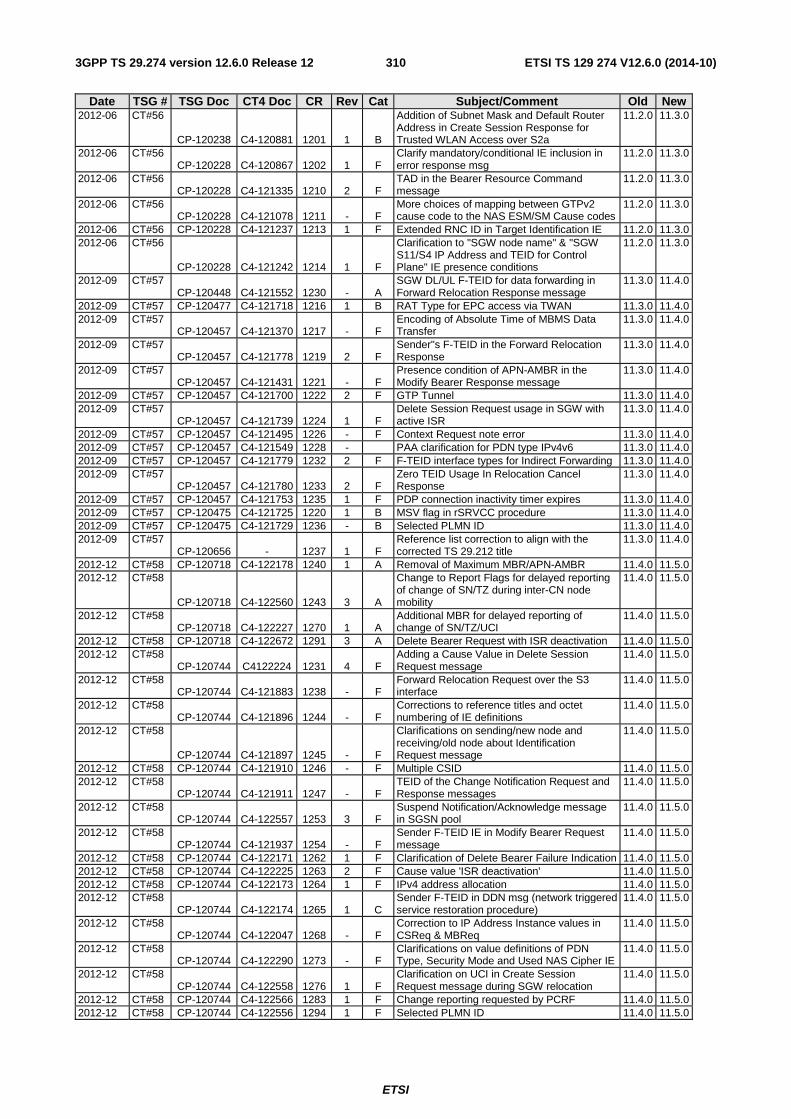
ETSI
ETSI TS 129 274 V12.6.0 (2014-10)3103GPP TS 29.274 version 12.6.0 Release 12
Date TSG # TSG Doc CT4 Doc CR Rev Cat Subject/Comment Old New 2012-06 CT#56
CP-120238 C4-120881 1201 1 B
Addition of Subnet Mask and Default Router Address in Create Session Response for Trusted WLAN Access over S2a
11.2.0 11.3.0
2012-06 CT#56 CP-120228 C4-120867 1202 1 F
Clarify mandatory/conditional IE inclusion in error response msg
11.2.0 11.3.0
2012-06 CT#56 CP-120228 C4-121335 1210 2 F
TAD in the Bearer Resource Command message
11.2.0 11.3.0
2012-06 CT#56 CP-120228 C4-121078 1211 - F
More choices of mapping between GTPv2 cause code to the NAS ESM/SM Cause codes
11.2.0 11.3.0
2012-06 CT#56 CP-120228 C4-121237 1213 1 F Extended RNC ID in Target Identification IE 11.2.0 11.3.0 2012-06 CT#56
CP-120228 C4-121242 1214 1 F
Clarification to "SGW node name" & "SGW S11/S4 IP Address and TEID for Control Plane" IE presence conditions
11.2.0 11.3.0
2012-09 CT#57 CP-120448 C4-121552 1230 - A
SGW DL/UL F-TEID for data forwarding in Forward Relocation Response message
11.3.0 11.4.0
2012-09 CT#57 CP-120477 C4-121718 1216 1 B RAT Type for EPC access via TWAN 11.3.0 11.4.0 2012-09 CT#57
CP-120457 C4-121370 1217 - F Encoding of Absolute Time of MBMS Data Transfer
11.3.0 11.4.0
2012-09 CT#57 CP-120457 C4-121778 1219 2 F
Sender"s F-TEID in the Forward Relocation Response
11.3.0 11.4.0
2012-09 CT#57 CP-120457 C4-121431 1221 - F
Presence condition of APN-AMBR in the Modify Bearer Response message
11.3.0 11.4.0
2012-09 CT#57 CP-120457 C4-121700 1222 2 F GTP Tunnel 11.3.0 11.4.0 2012-09 CT#57
CP-120457 C4-121739 1224 1 F Delete Session Request usage in SGW with active ISR
11.3.0 11.4.0
2012-09 CT#57 CP-120457 C4-121495 1226 - F Context Request note error 11.3.0 11.4.0 2012-09 CT#57 CP-120457 C4-121549 1228 - PAA clarification for PDN type IPv4v6 11.3.0 11.4.0 2012-09 CT#57 CP-120457 C4-121779 1232 2 F F-TEID interface types for Indirect Forwarding 11.3.0 11.4.0 2012-09 CT#57
CP-120457 C4-121780 1233 2 F Zero TEID Usage In Relocation Cancel Response
11.3.0 11.4.0
2012-09 CT#57 CP-120457 C4-121753 1235 1 F PDP connection inactivity timer expires 11.3.0 11.4.0 2012-09 CT#57 CP-120475 C4-121725 1220 1 B MSV flag in rSRVCC procedure 11.3.0 11.4.0 2012-09 CT#57 CP-120475 C4-121729 1236 - B Selected PLMN ID 11.3.0 11.4.0 2012-09 CT#57
CP-120656 - 1237 1 F Reference list correction to align with the corrected TS 29.212 title
11.3.0 11.4.0
2012-12 CT#58 CP-120718 C4-122178 1240 1 A Removal of Maximum MBR/APN-AMBR 11.4.0 11.5.0 2012-12 CT#58
CP-120718 C4-122560 1243 3 A
Change to Report Flags for delayed reporting of change of SN/TZ during inter-CN node mobility
11.4.0 11.5.0
2012-12 CT#58 CP-120718 C4-122227 1270 1 A
Additional MBR for delayed reporting of change of SN/TZ/UCI
11.4.0 11.5.0
2012-12 CT#58 CP-120718 C4-122672 1291 3 A Delete Bearer Request with ISR deactivation 11.4.0 11.5.0 2012-12 CT#58
CP-120744 C4122224 1231 4 F Adding a Cause Value in Delete Session Request message
11.4.0 11.5.0
2012-12 CT#58 CP-120744 C4-121883 1238 - F
Forward Relocation Request over the S3 interface
11.4.0 11.5.0
2012-12 CT#58 CP-120744 C4-121896 1244 - F
Corrections to reference titles and octet numbering of IE definitions
11.4.0 11.5.0
2012-12 CT#58
CP-120744 C4-121897 1245 - F
Clarifications on sending/new node and receiving/old node about Identification Request message
11.4.0 11.5.0
2012-12 CT#58 CP-120744 C4-121910 1246 - F Multiple CSID 11.4.0 11.5.0 2012-12 CT#58
CP-120744 C4-121911 1247 - F TEID of the Change Notification Request and Response messages
11.4.0 11.5.0
2012-12 CT#58 CP-120744 C4-122557 1253 3 F
Suspend Notification/Acknowledge message in SGSN pool
11.4.0 11.5.0
2012-12 CT#58 CP-120744 C4-121937 1254 - F
Sender F-TEID IE in Modify Bearer Request message
11.4.0 11.5.0
2012-12 CT#58 CP-120744 C4-122171 1262 1 F Clarification of Delete Bearer Failure Indication 11.4.0 11.5.0 2012-12 CT#58 CP-120744 C4-122225 1263 2 F Cause value 'ISR deactivation' 11.4.0 11.5.0 2012-12 CT#58 CP-120744 C4-122173 1264 1 F IPv4 address allocation 11.4.0 11.5.0 2012-12 CT#58
CP-120744 C4-122174 1265 1 C Sender F-TEID in DDN msg (network triggered service restoration procedure)
11.4.0 11.5.0
2012-12 CT#58 CP-120744 C4-122047 1268 - F
Correction to IP Address Instance values in CSReq & MBReq
11.4.0 11.5.0
2012-12 CT#58 CP-120744 C4-122290 1273 - F
Clarifications on value definitions of PDN Type, Security Mode and Used NAS Cipher IE
11.4.0 11.5.0
2012-12 CT#58 CP-120744 C4-122558 1276 1 F
Clarification on UCI in Create Session Request message during SGW relocation
11.4.0 11.5.0
2012-12 CT#58 CP-120744 C4-122566 1283 1 F Change reporting requested by PCRF 11.4.0 11.5.0 2012-12 CT#58 CP-120744 C4-122556 1294 1 F Selected PLMN ID 11.4.0 11.5.0
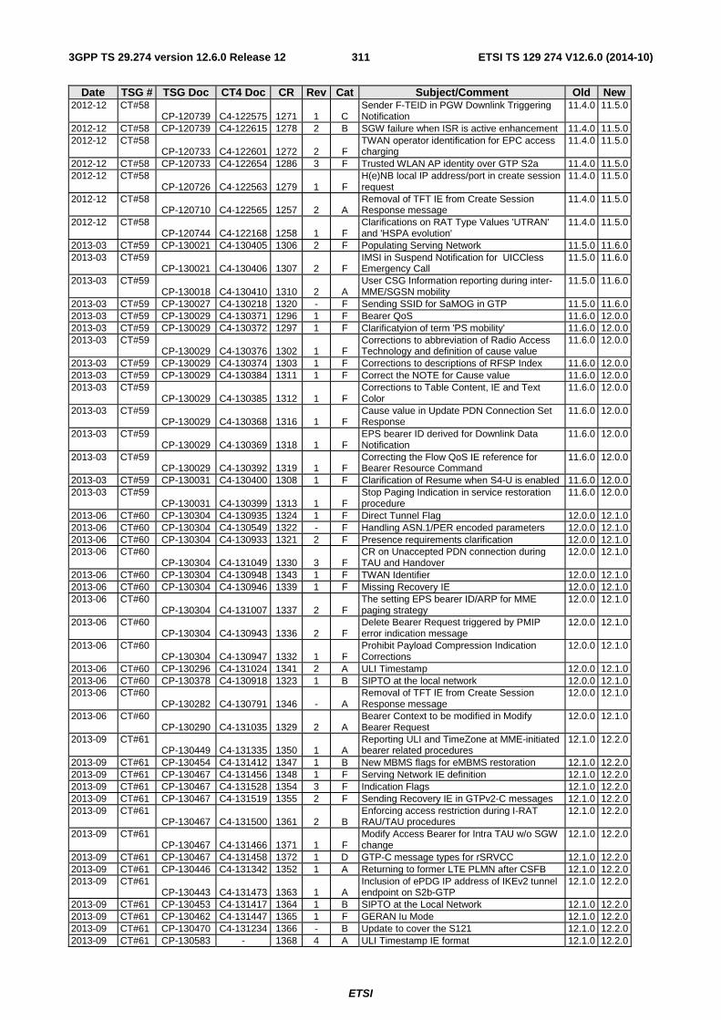
ETSI
ETSI TS 129 274 V12.6.0 (2014-10)3113GPP TS 29.274 version 12.6.0 Release 12
Date TSG # TSG Doc CT4 Doc CR Rev Cat Subject/Comment Old New 2012-12 CT#58
CP-120739 C4-122575 1271 1 C Sender F-TEID in PGW Downlink Triggering Notification
11.4.0 11.5.0
2012-12 CT#58 CP-120739 C4-122615 1278 2 B SGW failure when ISR is active enhancement 11.4.0 11.5.0 2012-12 CT#58
CP-120733 C4-122601 1272 2 F TWAN operator identification for EPC access charging
11.4.0 11.5.0
2012-12 CT#58 CP-120733 C4-122654 1286 3 F Trusted WLAN AP identity over GTP S2a 11.4.0 11.5.0 2012-12 CT#58
CP-120726 C4-122563 1279 1 F H(e)NB local IP address/port in create session request
11.4.0 11.5.0
2012-12 CT#58 CP-120710 C4-122565 1257 2 A
Removal of TFT IE from Create Session Response message
11.4.0 11.5.0
2012-12 CT#58 CP-120744 C4-122168 1258 1 F
Clarifications on RAT Type Values 'UTRAN' and 'HSPA evolution'
11.4.0 11.5.0
2013-03 CT#59 CP-130021 C4-130405 1306 2 F Populating Serving Network 11.5.0 11.6.0 2013-03 CT#59
CP-130021 C4-130406 1307 2 F IMSI in Suspend Notification for UICCless Emergency Call
11.5.0 11.6.0
2013-03 CT#59 CP-130018 C4-130410 1310 2 A
User CSG Information reporting during inter-MME/SGSN mobility
11.5.0 11.6.0
2013-03 CT#59 CP-130027 C4-130218 1320 - F Sending SSID for SaMOG in GTP 11.5.0 11.6.0 2013-03 CT#59 CP-130029 C4-130371 1296 1 F Bearer QoS 11.6.0 12.0.0 2013-03 CT#59 CP-130029 C4-130372 1297 1 F Clarificatyion of term 'PS mobility' 11.6.0 12.0.0 2013-03 CT#59
CP-130029 C4-130376 1302 1 F Corrections to abbreviation of Radio Access Technology and definition of cause value
11.6.0 12.0.0
2013-03 CT#59 CP-130029 C4-130374 1303 1 F Corrections to descriptions of RFSP Index 11.6.0 12.0.0 2013-03 CT#59 CP-130029 C4-130384 1311 1 F Correct the NOTE for Cause value 11.6.0 12.0.0 2013-03 CT#59
CP-130029 C4-130385 1312 1 F Corrections to Table Content, IE and Text Color
11.6.0 12.0.0
2013-03 CT#59 CP-130029 C4-130368 1316 1 F
Cause value in Update PDN Connection Set Response
11.6.0 12.0.0
2013-03 CT#59 CP-130029 C4-130369 1318 1 F
EPS bearer ID derived for Downlink Data Notification
11.6.0 12.0.0
2013-03 CT#59 CP-130029 C4-130392 1319 1 F
Correcting the Flow QoS IE reference for Bearer Resource Command
11.6.0 12.0.0
2013-03 CT#59 CP-130031 C4-130400 1308 1 F Clarification of Resume when S4-U is enabled 11.6.0 12.0.0 2013-03 CT#59
CP-130031 C4-130399 1313 1 F Stop Paging Indication in service restoration procedure
11.6.0 12.0.0
2013-06 CT#60 CP-130304 C4-130935 1324 1 F Direct Tunnel Flag 12.0.0 12.1.0 2013-06 CT#60 CP-130304 C4-130549 1322 - F Handling ASN.1/PER encoded parameters 12.0.0 12.1.0 2013-06 CT#60 CP-130304 C4-130933 1321 2 F Presence requirements clarification 12.0.0 12.1.0 2013-06 CT#60
CP-130304 C4-131049 1330 3 F CR on Unaccepted PDN connection during TAU and Handover
12.0.0 12.1.0
2013-06 CT#60 CP-130304 C4-130948 1343 1 F TWAN Identifier 12.0.0 12.1.0 2013-06 CT#60 CP-130304 C4-130946 1339 1 F Missing Recovery IE 12.0.0 12.1.0 2013-06 CT#60
CP-130304 C4-131007 1337 2 F The setting EPS bearer ID/ARP for MME paging strategy
12.0.0 12.1.0
2013-06 CT#60 CP-130304 C4-130943 1336 2 F
Delete Bearer Request triggered by PMIP error indication message
12.0.0 12.1.0
2013-06 CT#60 CP-130304 C4-130947 1332 1 F
Prohibit Payload Compression Indication Corrections
12.0.0 12.1.0
2013-06 CT#60 CP-130296 C4-131024 1341 2 A ULI Timestamp 12.0.0 12.1.0 2013-06 CT#60 CP-130378 C4-130918 1323 1 B SIPTO at the local network 12.0.0 12.1.0 2013-06 CT#60
CP-130282 C4-130791 1346 - A Removal of TFT IE from Create Session Response message
12.0.0 12.1.0
2013-06 CT#60 CP-130290 C4-131035 1329 2 A
Bearer Context to be modified in Modify Bearer Request
12.0.0 12.1.0
2013-09 CT#61 CP-130449 C4-131335 1350 1 A
Reporting ULI and TimeZone at MME-initiated bearer related procedures
12.1.0 12.2.0
2013-09 CT#61 CP-130454 C4-131412 1347 1 B New MBMS flags for eMBMS restoration 12.1.0 12.2.0 2013-09 CT#61 CP-130467 C4-131456 1348 1 F Serving Network IE definition 12.1.0 12.2.0 2013-09 CT#61 CP-130467 C4-131528 1354 3 F Indication Flags 12.1.0 12.2.0 2013-09 CT#61 CP-130467 C4-131519 1355 2 F Sending Recovery IE in GTPv2-C messages 12.1.0 12.2.0 2013-09 CT#61
CP-130467 C4-131500 1361 2 B Enforcing access restriction during I-RAT RAU/TAU procedures
12.1.0 12.2.0
2013-09 CT#61 CP-130467 C4-131466 1371 1 F
Modify Access Bearer for Intra TAU w/o SGW change
12.1.0 12.2.0
2013-09 CT#61 CP-130467 C4-131458 1372 1 D GTP-C message types for rSRVCC 12.1.0 12.2.0 2013-09 CT#61 CP-130446 C4-131342 1352 1 A Returning to former LTE PLMN after CSFB 12.1.0 12.2.0 2013-09 CT#61
CP-130443 C4-131473 1363 1 A Inclusion of ePDG IP address of IKEv2 tunnel endpoint on S2b-GTP
12.1.0 12.2.0
2013-09 CT#61 CP-130453 C4-131417 1364 1 B SIPTO at the Local Network 12.1.0 12.2.0 2013-09 CT#61 CP-130462 C4-131447 1365 1 F GERAN Iu Mode 12.1.0 12.2.0 2013-09 CT#61 CP-130470 C4-131234 1366 - B Update to cover the S121 12.1.0 12.2.0 2013-09 CT#61 CP-130583 - 1368 4 A ULI Timestamp IE format 12.1.0 12.2.0
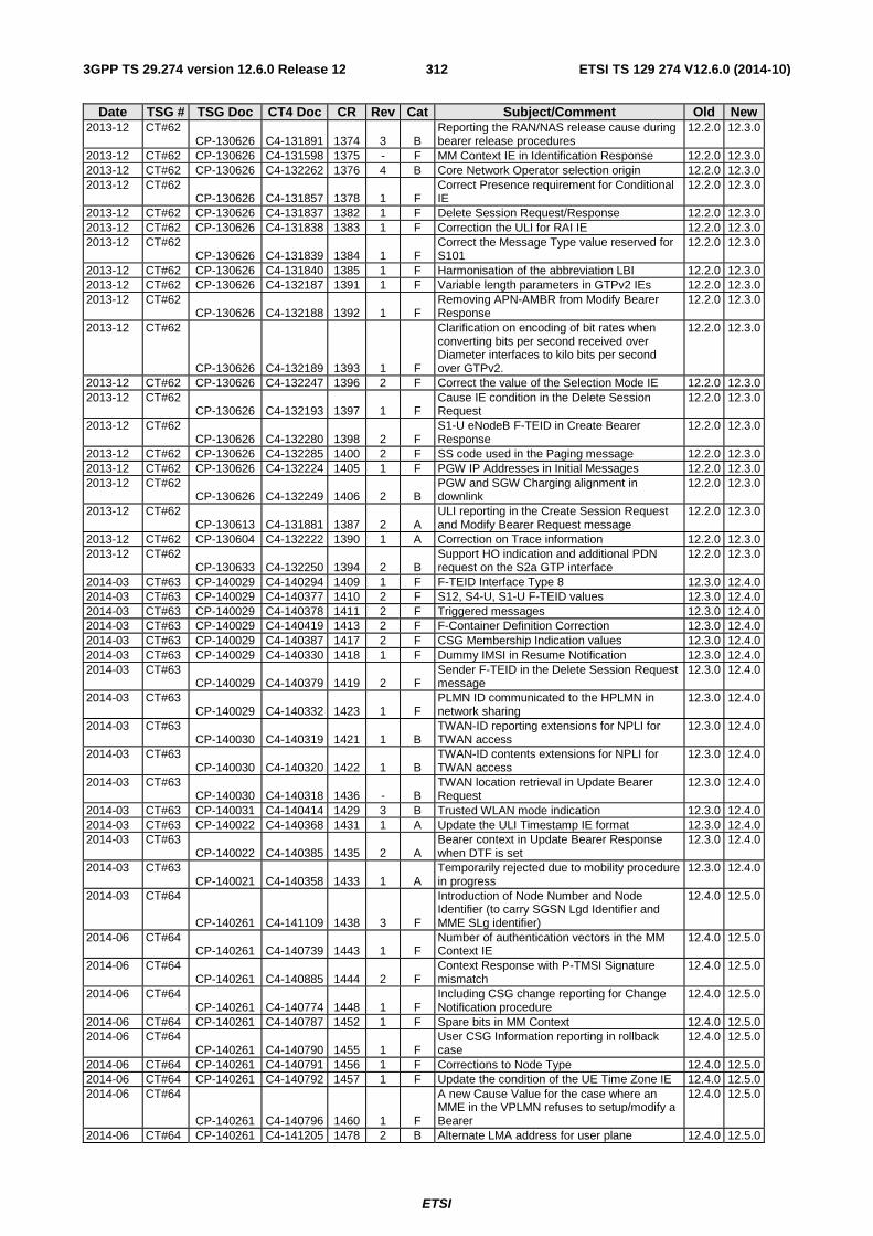
ETSI
ETSI TS 129 274 V12.6.0 (2014-10)3123GPP TS 29.274 version 12.6.0 Release 12
Date TSG # TSG Doc CT4 Doc CR Rev Cat Subject/Comment Old New 2013-12 CT#62
CP-130626 C4-131891 1374 3 B Reporting the RAN/NAS release cause during bearer release procedures
12.2.0 12.3.0
2013-12 CT#62 CP-130626 C4-131598 1375 - F MM Context IE in Identification Response 12.2.0 12.3.0 2013-12 CT#62 CP-130626 C4-132262 1376 4 B Core Network Operator selection origin 12.2.0 12.3.0 2013-12 CT#62
CP-130626 C4-131857 1378 1 F Correct Presence requirement for Conditional IE
12.2.0 12.3.0
2013-12 CT#62 CP-130626 C4-131837 1382 1 F Delete Session Request/Response 12.2.0 12.3.0 2013-12 CT#62 CP-130626 C4-131838 1383 1 F Correction the ULI for RAI IE 12.2.0 12.3.0 2013-12 CT#62
CP-130626 C4-131839 1384 1 F Correct the Message Type value reserved for S101
12.2.0 12.3.0
2013-12 CT#62 CP-130626 C4-131840 1385 1 F Harmonisation of the abbreviation LBI 12.2.0 12.3.0 2013-12 CT#62 CP-130626 C4-132187 1391 1 F Variable length parameters in GTPv2 IEs 12.2.0 12.3.0 2013-12 CT#62
CP-130626 C4-132188 1392 1 F Removing APN-AMBR from Modify Bearer Response
12.2.0 12.3.0
2013-12 CT#62
CP-130626 C4-132189 1393 1 F
Clarification on encoding of bit rates when converting bits per second received over Diameter interfaces to kilo bits per second over GTPv2.
12.2.0 12.3.0
2013-12 CT#62 CP-130626 C4-132247 1396 2 F Correct the value of the Selection Mode IE 12.2.0 12.3.0 2013-12 CT#62
CP-130626 C4-132193 1397 1 F Cause IE condition in the Delete Session Request
12.2.0 12.3.0
2013-12 CT#62 CP-130626 C4-132280 1398 2 F
S1-U eNodeB F-TEID in Create Bearer Response
12.2.0 12.3.0
2013-12 CT#62 CP-130626 C4-132285 1400 2 F SS code used in the Paging message 12.2.0 12.3.0 2013-12 CT#62 CP-130626 C4-132224 1405 1 F PGW IP Addresses in Initial Messages 12.2.0 12.3.0 2013-12 CT#62
CP-130626 C4-132249 1406 2 B PGW and SGW Charging alignment in downlink
12.2.0 12.3.0
2013-12 CT#62 CP-130613 C4-131881 1387 2 A
ULI reporting in the Create Session Request and Modify Bearer Request message
12.2.0 12.3.0
2013-12 CT#62 CP-130604 C4-132222 1390 1 A Correction on Trace information 12.2.0 12.3.0 2013-12 CT#62
CP-130633 C4-132250 1394 2 B Support HO indication and additional PDN request on the S2a GTP interface
12.2.0 12.3.0
2014-03 CT#63 CP-140029 C4-140294 1409 1 F F-TEID Interface Type 8 12.3.0 12.4.0 2014-03 CT#63 CP-140029 C4-140377 1410 2 F S12, S4-U, S1-U F-TEID values 12.3.0 12.4.0 2014-03 CT#63 CP-140029 C4-140378 1411 2 F Triggered messages 12.3.0 12.4.0 2014-03 CT#63 CP-140029 C4-140419 1413 2 F F-Container Definition Correction 12.3.0 12.4.0 2014-03 CT#63 CP-140029 C4-140387 1417 2 F CSG Membership Indication values 12.3.0 12.4.0 2014-03 CT#63 CP-140029 C4-140330 1418 1 F Dummy IMSI in Resume Notification 12.3.0 12.4.0 2014-03 CT#63
CP-140029 C4-140379 1419 2 F Sender F-TEID in the Delete Session Request message
12.3.0 12.4.0
2014-03 CT#63 CP-140029 C4-140332 1423 1 F
PLMN ID communicated to the HPLMN in network sharing
12.3.0 12.4.0
2014-03 CT#63 CP-140030 C4-140319 1421 1 B
TWAN-ID reporting extensions for NPLI for TWAN access
12.3.0 12.4.0
2014-03 CT#63 CP-140030 C4-140320 1422 1 B
TWAN-ID contents extensions for NPLI for TWAN access
12.3.0 12.4.0
2014-03 CT#63 CP-140030 C4-140318 1436 - B
TWAN location retrieval in Update Bearer Request
12.3.0 12.4.0
2014-03 CT#63 CP-140031 C4-140414 1429 3 B Trusted WLAN mode indication 12.3.0 12.4.0 2014-03 CT#63 CP-140022 C4-140368 1431 1 A Update the ULI Timestamp IE format 12.3.0 12.4.0 2014-03 CT#63
CP-140022 C4-140385 1435 2 A Bearer context in Update Bearer Response when DTF is set
12.3.0 12.4.0
2014-03 CT#63 CP-140021 C4-140358 1433 1 A
Temporarily rejected due to mobility procedure in progress
12.3.0 12.4.0
2014-03 CT#64
CP-140261 C4-141109 1438 3 F
Introduction of Node Number and Node Identifier (to carry SGSN Lgd Identifier and MME SLg identifier)
12.4.0 12.5.0
2014-06 CT#64 CP-140261 C4-140739 1443 1 F
Number of authentication vectors in the MM Context IE
12.4.0 12.5.0
2014-06 CT#64 CP-140261 C4-140885 1444 2 F
Context Response with P-TMSI Signature mismatch
12.4.0 12.5.0
2014-06 CT#64 CP-140261 C4-140774 1448 1 F
Including CSG change reporting for Change Notification procedure
12.4.0 12.5.0
2014-06 CT#64 CP-140261 C4-140787 1452 1 F Spare bits in MM Context 12.4.0 12.5.0 2014-06 CT#64
CP-140261 C4-140790 1455 1 F User CSG Information reporting in rollback case
12.4.0 12.5.0
2014-06 CT#64 CP-140261 C4-140791 1456 1 F Corrections to Node Type 12.4.0 12.5.0 2014-06 CT#64 CP-140261 C4-140792 1457 1 F Update the condition of the UE Time Zone IE 12.4.0 12.5.0 2014-06 CT#64
CP-140261 C4-140796 1460 1 F
A new Cause Value for the case where an MME in the VPLMN refuses to setup/modify a Bearer
12.4.0 12.5.0
2014-06 CT#64 CP-140261 C4-141205 1478 2 B Alternate LMA address for user plane 12.4.0 12.5.0
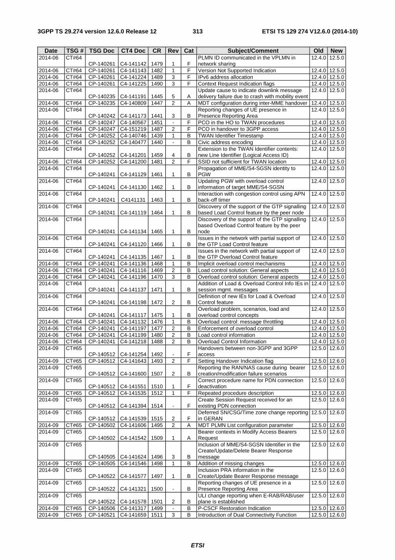
ETSI
ETSI TS 129 274 V12.6.0 (2014-10)3133GPP TS 29.274 version 12.6.0 Release 12
Date TSG # TSG Doc CT4 Doc CR Rev Cat Subject/Comment Old New 2014-06 CT#64
CP-140261 C4-141142 1479 1 F PLMN ID communicated in the VPLMN in network sharing
12.4.0 12.5.0
2014-06 CT#64 CP-140261 C4-141143 1482 1 F Version Not Supported Indication 12.4.0 12.5.0 2014-06 CT#64 CP-140261 C4-141224 1489 3 F IPv6 address allocation 12.4.0 12.5.0 2014-06 CT#64 CP-140261 C4-141225 1490 3 F Context Request Indication flags 12.4.0 12.5.0 2014-06 CT#64
CP-140235 C4-141191 1445 5 A Update cause to indicate downlink message delivery failure due to crash with mobility event
12.4.0 12.5.0
2014-06 CT#64 CP-140235 C4-140809 1447 2 A MDT configuration during inter-MME handover 12.4.0 12.5.0 2014-06 CT#64
CP-140242 C4-141173 1441 3 B Reporting changes of UE presence in Presence Reporting Area
12.4.0 12.5.0
2014-06 CT#64 CP-140247 C4-140567 1451 - F PCO in the HO to TWAN procedures 12.4.0 12.5.0 2014-06 CT#64 CP-140247 C4-151219 1487 2 F PCO in handover to 3GPP access 12.4.0 12.5.0 2014-06 CT#64 CP-140252 C4-140746 1439 1 B TWAN Identifier Timestamp 12.4.0 12.5.0 2014-06 CT#64 CP-140252 C4-140477 1440 - B Civic address encoding 12.4.0 12.5.0 2014-06 CT#64
CP-140252 C4-141201 1459 4 B Extension to the TWAN Identifier contents: new Line Identifier (Logical Access ID)
12.4.0 12.5.0
2014-06 CT#64 CP-140252 C4-141200 1481 2 F SSID not sufficient for TWAN location 12.4.0 12.5.0 2014-06 CT#64
CP-140241 C4-141129 1461 1 B Propagation of MME/S4-SGSN identity to PGW
12.4.0 12.5.0
2014-06 CT#64 CP-140241 C4-141130 1462 1 B
Updating PGW with overload control information of target MME/S4-SGSN
12.4.0 12.5.0
2014-06 CT#64 CP-140241 C4141131 1463 1 B
Interaction with congestion control using APN back-off timer
12.4.0 12.5.0
2014-06 CT#64 CP-140241 C4-141119 1464 1 B
Discovery of the support of the GTP signalling based Load Control feature by the peer node
12.4.0 12.5.0
2014-06 CT#64
CP-140241 C4-141134 1465 1 B
Discovery of the support of the GTP signalling based Overload Control feature by the peer node
12.4.0 12.5.0
2014-06 CT#64 CP-140241 C4-141120 1466 1 B
Issues in the network with partial support of the GTP Load Control feature
12.4.0 12.5.0
2014-06 CT#64 CP-140241 C4-141135 1467 1 B
Issues in the network with partial support of the GTP Overload Control feature
12.4.0 12.5.0
2014-06 CT#64 CP-140241 C4-141136 1468 1 B Implicit overload control mechanisms 12.4.0 12.5.0 2014-06 CT#64 CP-140241 C4-141116 1469 2 B Load control solution: General aspects 12.4.0 12.5.0 2014-06 CT#64 CP-140241 C4-141196 1470 3 B Overload control solution: General aspects 12.4.0 12.5.0 2014-06 CT#64
CP-140241 C4-141137 1471 1 B Addition of Load & Overload Control Info IEs in session mgmt. messages
12.4.0 12.5.0
2014-06 CT#64 CP-140241 C4-141198 1472 2 B
Definition of new IEs for Load & Overload Control feature
12.4.0 12.5.0
2014-06 CT#64 CP-140241 C4-141117 1475 1 B
Overload problem, scenarios, load and overload control concepts
12.4.0 12.5.0
2014-06 CT#64 CP-140241 C4-141132 1476 1 B Overload control: message throttling 12.4.0 12.5.0 2014-06 CT#64 CP-140241 C4-141197 1477 2 B Enforcement of overload control 12.4.0 12.5.0 2014-06 CT#64 CP-140241 C4-141199 1480 2 B Load control information 12.4.0 12.5.0 2014-06 CT#64 CP-140241 C4-141218 1488 2 B Overload Control Information 12.4.0 12.5.0 2014-09 CT#65
CP-140512 C4-141254 1492 - F Handovers between non-3GPP and 3GPP access
12.5.0 12.6.0
2014-09 CT#65 CP-140512 C4-141643 1493 2 F Setting Handover Indication flag 12.5.0 12.6.0 2014-09 CT#65
CP-140512 C4-141600 1507 2 B Reporting the RAN/NAS cause during bearer creation/modification failure scenarios
12.5.0 12.6.0
2014-09 CT#65 CP-140512 C4-141551 1510 1 F
Correct procedure name for PDN connection deactivation
12.5.0 12.6.0
2014-09 CT#65 CP-140512 C4-141535 1512 1 F Repeated procedure description 12.5.0 12.6.0 2014-09 CT#65
CP-140512 C4-141394 1514 - F Create Session Request received for an existing PDN connection
12.5.0 12.6.0
2014-09 CT#65 CP-140512 C4-141539 1515 2 F
Deferred SN/CSG/Time zone change reporting in GERAN
12.5.0 12.6.0
2014-09 CT#65 CP-140502 C4-141606 1495 2 A MDT PLMN List configuration parameter 12.5.0 12.6.0 2014-09 CT#65
CP-140502 C4-141542 1509 1 A Bearer contexts in Modify Access Bearers Request
12.5.0 12.6.0
2014-09 CT#65
CP-140505 C4-141624 1496 3 B
Inclusion of MME/S4-SGSN Identifier in the Create/Update/Delete Bearer Response message
12.5.0 12.6.0
2014-09 CT#65 CP-140505 C4-141546 1498 1 B Addition of missing changes 12.5.0 12.6.0 2014-09 CT#65
CP-140522 C4-141577 1497 1 B Inclusion PRA information in the Create/Update Bearer Response message
12.5.0 12.6.0
2014-09 CT#65 CP-140522 C4-141321 1500 - B
Reporting changes of UE presence in a Presence Reporting Area
12.5.0 12.6.0
2014-09 CT#65 CP-140522 C4-141578 1501 2 B
ULI change reporting when E-RAB/RAB/user plane is established
12.5.0 12.6.0
2014-09 CT#65 CP-140506 C4-141317 1499 - B P-CSCF Restoration Indication 12.5.0 12.6.0 2014-09 CT#65 CP-140521 C4-141659 1511 3 B Introduction of Dual Connectivity Function 12.5.0 12.6.0

ETSI
ETSI TS 129 274 V12.6.0 (2014-10)3143GPP TS 29.274 version 12.6.0 Release 12
Date TSG # TSG Doc CT4 Doc CR Rev Cat Subject/Comment Old New 2014-09 CT#65
CP-140518 C4-141602 1513 2 B PGW F-TEID in the PGW Downlink Triggering Notification
12.5.0 12.6.0
2014-09 CT#65 CP-140501 C4-141560 1518 - A
BSS container in Forward Relocation Request / Response
12.5.0 12.6.0

ETSI
ETSI TS 129 274 V12.6.0 (2014-10)3153GPP TS 29.274 version 12.6.0 Release 12
History
Document history
V12.6.0 October 2014 Publication