Three-Phase BLDC Motor SensorlessControl Using MC56F8013/23
Design Reference ManualDevices Supported:
56F801x 56F802x
Document Number: DRM070Rev. 2
08/2007

How to Reach Us:
Home Page:www.freescale.com
E-mail:[email protected]
USA/Europe or Locations Not Listed:Freescale SemiconductorTechnical Information Center, CH3701300 N. Alma School RoadChandler, Arizona 85224+1-800-521-6274 or [email protected]
Europe, Middle East, and Africa:Freescale Halbleiter Deutschland GmbHTechnical Information CenterSchatzbogen 781829 Muenchen, Germany+44 1296 380 456 (English)+46 8 52200080 (English)+49 89 92103 559 (German)+33 1 69 35 48 48 (French)[email protected]
Japan:Freescale Semiconductor Japan Ltd.HeadquartersARCO Tower 15F1-8-1, Shimo-Meguro, Meguro-ku,Tokyo 153-0064, Japan0120 191014 or +81 3 5437 [email protected]
Asia/Pacific:Freescale Semiconductor Hong Kong Ltd.Technical Information Center2 Dai King StreetTai Po Industrial EstateTai Po, N.T., Hong Kong+800 [email protected]
For Literature Requests Only:Freescale Semiconductor Literature Distribution CenterP.O. Box 5405Denver, Colorado 802171-800-441-2447 or 303-675-2140Fax: [email protected]
Information in this document is provided solely to enable system and software implementers to use Freescale Semiconductor products. There are no express or implied copyright licenses granted hereunder to design or fabricate any integrated circuits or integrated circuits based on the information in this document.
Freescale Semiconductor reserves the right to make changes without further notice to any products herein. Freescale Semiconductor makes no warranty, representation or guarantee regarding the suitability of its products for any particular purpose, nor does Freescale Semiconductor assume any liability arising out of the application or use of any product or circuit, and specifically disclaims any and all liability, including without limitation consequential or incidental damages. “Typical” parameters that may be provided in Freescale Semiconductor data sheets and/or specifications can and do vary in different applications and actual performance may vary over time. All operating parameters, including “Typicals”, must be validated for each customer application by customer’s technical experts. Freescale Semiconductor does not convey any license under its patent rights nor the rights of others. Freescale Semiconductor products are not designed, intended, or authorized for use as components in systems intended for surgical implant into the body, or other applications intended to support or sustain life, or for any other application in which the failure of the Freescale Semiconductor product could create a situation where personal injury or death may occur. Should Buyer purchase or use Freescale Semiconductor products for any such unintended or unauthorized application, Buyer shall indemnify and hold Freescale Semiconductor and its officers, employees, subsidiaries, affiliates, and distributors harmless against all claims, costs, damages, and expenses, and reasonable attorney fees arising out of, directly or indirectly, any claim of personal injury or death associated with such unintended or unauthorized use, even if such claim alleges that Freescale Semiconductor was negligent regarding the design or manufacture of the part.
Freescale™ and the Freescale logo are trademarks of Freescale Semiconductor, Inc. The ARM POWERED logo is a registered trademark of ARM Limited. ARM7TDMI-S is a trademark of ARM Limited.Java and all other Java-based marks are trademarks or registeredtrademarks of Sun Microsystems, Inc. in the U.S. and other countries.The PowerPC name is a trademark of IBM Corp. and is used under license.The described product contains a PowerPC processor core. The PowerPC name is a trademark of IBM Corp. and used under license. The described product is a PowerPC microprocessor. The PowerPC name is a trademark of IBM Corp. and is used under license. The described product is a PowerPC microprocessor core. The PowerPC name is a trademark of IBM Corp. and is used under license. All other product or service names are the property of their respective owners.
© Freescale Semiconductor, Inc. 2007. All rights reserved.
DRM070Rev. 208/2007
Three-Phase BLDC Motor Sensorless Control Using MC56F8013/23, Rev. 2
Freescale Semiconductor -1
Chapter 1Introduction
1.1 Introduction. . . . . . . . . . . . . . . . . . . . . . . . . . . . . . . . . . . . . . . . . . . . . . . . . . . . . . . . . . . 1-11.1.1 Pump, Fan, and Compressor Applications . . . . . . . . . . . . . . . . . . . . . . . . . . . . 1-11.1.2 Why Sensorless Control? . . . . . . . . . . . . . . . . . . . . . . . . . . . . . . . . . . . . . . . . . 1-1
1.2 Freescale Digital Signal Controllers Advantages and Features . . . . . . . . . . . . . . . . . . . 1-21.2.1 MC56F801x Family Features . . . . . . . . . . . . . . . . . . . . . . . . . . . . . . . . . . . . . . 1-21.2.2 MC56F802x Family Features . . . . . . . . . . . . . . . . . . . . . . . . . . . . . . . . . . . . . . 1-31.2.3 BLDC Motor Control Specific Features of MC56F8000 Family . . . . . . . . . . . . . 1-4
Chapter 2Control
2.1 Brushless DC Motor (BLDC Motor) . . . . . . . . . . . . . . . . . . . . . . . . . . . . . . . . . . . . . . . . 1-12.2 Power Stage . . . . . . . . . . . . . . . . . . . . . . . . . . . . . . . . . . . . . . . . . . . . . . . . . . . . . . . . . . 1-42.3 Mathematical Description of Brushless DC Motor . . . . . . . . . . . . . . . . . . . . . . . . . . . . . 1-5
2.3.1 Power Stage – Motor System Model . . . . . . . . . . . . . . . . . . . . . . . . . . . . . . . . . 1-52.3.2 Mathematical Model. . . . . . . . . . . . . . . . . . . . . . . . . . . . . . . . . . . . . . . . . . . . . . 1-62.3.3 Back-EMF Sensing . . . . . . . . . . . . . . . . . . . . . . . . . . . . . . . . . . . . . . . . . . . . . . 1-7
Chapter 3Hardware
3.1 Hardware Implementation . . . . . . . . . . . . . . . . . . . . . . . . . . . . . . . . . . . . . . . . . . . . . . . 1-13.1.1 Hardware Implementation with EVM33395 Evaluation Motor Board. . . . . . . . . 1-23.1.2 Hardware Implementation with Micro Power Board. . . . . . . . . . . . . . . . . . . . . . 1-3
3.2 Component Descriptions . . . . . . . . . . . . . . . . . . . . . . . . . . . . . . . . . . . . . . . . . . . . . . . . 1-33.2.1 MC56F8013/23 Controller Board. . . . . . . . . . . . . . . . . . . . . . . . . . . . . . . . . . . . 1-33.2.2 Power Stage Boards . . . . . . . . . . . . . . . . . . . . . . . . . . . . . . . . . . . . . . . . . . . . . 1-53.2.3 Motors . . . . . . . . . . . . . . . . . . . . . . . . . . . . . . . . . . . . . . . . . . . . . . . . . . . . . . . . 1-9
Chapter 4System
4.1 System Specification . . . . . . . . . . . . . . . . . . . . . . . . . . . . . . . . . . . . . . . . . . . . . . . . . . . 1-14.2 Sensorless Drive Concept . . . . . . . . . . . . . . . . . . . . . . . . . . . . . . . . . . . . . . . . . . . . . . . 1-14.3 System Blocks Concept . . . . . . . . . . . . . . . . . . . . . . . . . . . . . . . . . . . . . . . . . . . . . . . . . 1-3
4.3.1 PWM Voltage Generation for Brushless DC Motor . . . . . . . . . . . . . . . . . . . . . . 1-34.3.2 A/D Converter Sampling Mechanism. . . . . . . . . . . . . . . . . . . . . . . . . . . . . . . . . 1-54.3.3 Back-EMF Zero Crossing Sensing . . . . . . . . . . . . . . . . . . . . . . . . . . . . . . . . . . 1-74.3.4 Sensorless Commutation Control . . . . . . . . . . . . . . . . . . . . . . . . . . . . . . . . . . . 1-9
Chapter 5Software Design
5.1 Introduction. . . . . . . . . . . . . . . . . . . . . . . . . . . . . . . . . . . . . . . . . . . . . . . . . . . . . . . . . . . 1-1

Three-Phase BLDC Motor Sensorless Control Using MC56F8013/23, Rev. 2
Freescale Semiconductor -2
5.2 Main Software Flow Chart . . . . . . . . . . . . . . . . . . . . . . . . . . . . . . . . . . . . . . . . . . . . . . . 1-15.3 Data Flow . . . . . . . . . . . . . . . . . . . . . . . . . . . . . . . . . . . . . . . . . . . . . . . . . . . . . . . . . . . . 1-4
5.3.1 Process Application State Machine . . . . . . . . . . . . . . . . . . . . . . . . . . . . . . . . . . 1-55.3.2 Process Commutation Control. . . . . . . . . . . . . . . . . . . . . . . . . . . . . . . . . . . . . . 1-55.3.3 Process A/D Converter Zero Crossing Checking . . . . . . . . . . . . . . . . . . . . . . . 1-55.3.4 Process Zero Crossing Offset Setting . . . . . . . . . . . . . . . . . . . . . . . . . . . . . . . . 1-55.3.5 Process Speed PI Controller . . . . . . . . . . . . . . . . . . . . . . . . . . . . . . . . . . . . . . . 1-55.3.6 Process Alignment Current PI Controller. . . . . . . . . . . . . . . . . . . . . . . . . . . . . . 1-65.3.7 Process Current Limitation PI Controller . . . . . . . . . . . . . . . . . . . . . . . . . . . . . . 1-65.3.8 Process PWM Generation . . . . . . . . . . . . . . . . . . . . . . . . . . . . . . . . . . . . . . . . . 1-75.3.9 Process Fault Control . . . . . . . . . . . . . . . . . . . . . . . . . . . . . . . . . . . . . . . . . . . . 1-7
Chapter 6Application Set-Up
6.1 Application Description . . . . . . . . . . . . . . . . . . . . . . . . . . . . . . . . . . . . . . . . . . . . . . . . . . 1-16.1.1 Control Process . . . . . . . . . . . . . . . . . . . . . . . . . . . . . . . . . . . . . . . . . . . . . . . . . 1-26.1.2 Drive Protection . . . . . . . . . . . . . . . . . . . . . . . . . . . . . . . . . . . . . . . . . . . . . . . . . 1-36.1.3 FreeMASTER Interface . . . . . . . . . . . . . . . . . . . . . . . . . . . . . . . . . . . . . . . . . . . 1-3
6.2 Application Set-Up . . . . . . . . . . . . . . . . . . . . . . . . . . . . . . . . . . . . . . . . . . . . . . . . . . . . . 1-66.2.1 MC56F8013/23 Controller Board Set-Up. . . . . . . . . . . . . . . . . . . . . . . . . . . . . . 1-8
6.3 Projects Files . . . . . . . . . . . . . . . . . . . . . . . . . . . . . . . . . . . . . . . . . . . . . . . . . . . . . . . . 1-106.4 Application Build and Execute . . . . . . . . . . . . . . . . . . . . . . . . . . . . . . . . . . . . . . . . . . . 1-11
Chapter 7Tuning
7.1 Introduction. . . . . . . . . . . . . . . . . . . . . . . . . . . . . . . . . . . . . . . . . . . . . . . . . . . . . . . . . . . 1-17.2 Classification . . . . . . . . . . . . . . . . . . . . . . . . . . . . . . . . . . . . . . . . . . . . . . . . . . . . . . . . . 1-17.3 Application Related Parameters . . . . . . . . . . . . . . . . . . . . . . . . . . . . . . . . . . . . . . . . . . . 1-2
7.3.1 Parameters Defined in bldczcdefines.h . . . . . . . . . . . . . . . . . . . . . . . . . . . . . . . 1-27.3.2 Parameters Defined in bldcdrv.h (Masks) . . . . . . . . . . . . . . . . . . . . . . . . . . . . . 1-57.3.3 PWM mode selection definition . . . . . . . . . . . . . . . . . . . . . . . . . . . . . . . . . . . . . 1-5
7.4 Power Stage Related Parameters . . . . . . . . . . . . . . . . . . . . . . . . . . . . . . . . . . . . . . . . . 1-77.4.1 Parameters Summary . . . . . . . . . . . . . . . . . . . . . . . . . . . . . . . . . . . . . . . . . . . . 1-77.4.2 APP_VOLT_MAX . . . . . . . . . . . . . . . . . . . . . . . . . . . . . . . . . . . . . . . . . . . . . . . 1-77.4.3 APP_CUR_MAX . . . . . . . . . . . . . . . . . . . . . . . . . . . . . . . . . . . . . . . . . . . . . . . . 1-87.4.4 DC_UNDERVOLTAGE . . . . . . . . . . . . . . . . . . . . . . . . . . . . . . . . . . . . . . . . . . . 1-87.4.5 DC_OVERVOLTAGE . . . . . . . . . . . . . . . . . . . . . . . . . . . . . . . . . . . . . . . . . . . . 1-87.4.6 DC_OVERCURRENT . . . . . . . . . . . . . . . . . . . . . . . . . . . . . . . . . . . . . . . . . . . . 1-8
7.5 Motor Related Parameters . . . . . . . . . . . . . . . . . . . . . . . . . . . . . . . . . . . . . . . . . . . . . . . 1-87.5.1 Alignment Parameters . . . . . . . . . . . . . . . . . . . . . . . . . . . . . . . . . . . . . . . . . . . . 1-97.5.2 Start Parameters . . . . . . . . . . . . . . . . . . . . . . . . . . . . . . . . . . . . . . . . . . . . . . . 1-107.5.3 Run Parameters. . . . . . . . . . . . . . . . . . . . . . . . . . . . . . . . . . . . . . . . . . . . . . . . 1-127.5.4 General Parameters . . . . . . . . . . . . . . . . . . . . . . . . . . . . . . . . . . . . . . . . . . . . 1-15

Three-Phase BLDC Motor Sensorless Control Using MC56F8013/23, Rev. 2
Freescale Semiconductor -3
7.5.5 Controller Parameters . . . . . . . . . . . . . . . . . . . . . . . . . . . . . . . . . . . . . . . . . . . 1-16
Appendix AGlossary

Three-Phase BLDC Motor Sensorless Control Using MC56F8013/23, Rev. 2
Freescale Semiconductor-4

Three-Phase BLDC Motor Sensorless Control Using MC56F8013/23, Rev. 2
Freescale Semiconductor 1-1
Chapter 1 Introduction
1.1 IntroductionThis document describes the design of a three-phase brushless DC motor (BLDC motor) drive based on Freescale’s MC56F8013 and MC56F8023 dedicated motor control device.
Brushless DC motors are popular in a wide application area. The lack of a commutator makes the brushless DC motor more reliable than the DC motor. The brushless DC motor also has advantages when compared to an AC induction motor. Because a brushless DC motor achieves higher efficiency by generating the rotor magnetic flux with rotor magnets, it is used in high-end white goods (such as refrigerators, washing machines, dishwashers), high-end pumps, fans, and other appliances that require high reliability and efficiency.
The concept of the application is a speed closed-loop, trapezoidal brushless DC drive using a Back-EMF sensing control technique. It serves as an example of a brushless DC motor control design using a Freescale digital signal controllers (DSC).
This reference design includes basic motor theory, system design concept, hardware implementation, software design, and tuning considerations, including the FreeMASTER software visualization tool.
1.1.1 Pump, Fan, and Compressor Applications
Brushless DC motors are widely used in pump, fan, and compressor applications because of their robust structure. These applications do not usually require stand-still operation. Only speed information is needed and enough to perform control. This allows BLDC motors to be used, without any comlex control algorithm. Moreover, the sensorless control without any high complexity makes the brushless DC motors very ideal for pump, fan, and compressor applications. The aim of this reference manual is presenting an ideal solution with brushless DC motor for these applications.
1.1.2 Why Sensorless Control?
In BLDC motor, the rotor position must be known to energize the phase pair and control phase voltage. If any sensors are used to detect rotor position, sensed information must be transferred to a control unit.

Introduction
Three-Phase BLDC Motor Sensorless Control Using MC56F8013/23, Rev. 2
1-2 Freescale Semiconductor
Figure 1-1. Classical System
Therefore, additional connections to the motor are necessary. This may not be acceptable for some kind of applications. There are at least two reasons why you might want to eliminate the position sensors: impossible to make additional connections between position sensors and the control unit cost of the position sensors and wiring.
The first reason might be solved by integration of the driver within the motor body. However, a significant number of applications requiring a sensorless solution remain.
1.2 Freescale Digital Signal Controllers Advantages and Features
1.2.1 MC56F801x Family Features
The Freescale MC56F801x family is a member of 56F8000 product series.This is ideal for digital motor control, combining the DSP’s calculation capability with the MCU’s controller features on a single chip. These digital signal controllers offer many dedicated peripherals, such as pulse width modulation (PWM) module(s), an analog-to-digital converter (A/D converter), timers, communication peripherals (SCI, SPI, I2C), on-board flash, and RAM.
The MC56F801x family members provide the following peripheral blocks:• One pulse width modulator module (although limited pin out on MC56F8014 and MC56F8011)
with PWM outputs, fault inputs, fault tolerant design with dead-time insertion; supports center- and edge-aligned modes
• 12-bit A/D converters that support two simultaneous conversions; A/D converter and PWM modules can be synchronized
• One dedicated 16-bit general purpose quad timer module• One serial peripheral interface (SPI)• One serial communications interface (SCI) with LIN slave functionality• One inter-integrated circuit (I2C) port• On-board 3.3 down to 2.5 volt voltage regulator for powering internal logic and memories.• Integrated power-on-reset and low-voltage interrupt module
Power Stage
Control Unit
=
~
Speed
Setpoint
AC Line Voltage
Load
Position Sensor
MOTOR DRIVE
M

Introduction
Three-Phase BLDC Motor Sensorless Control Using MC56F8013/23, Rev. 2
Freescale Semiconductor 1-3
• All pins are muxed with GPIO• Computer operating properly (COP) watchdog timer• External reset input pin for hardware reset• JTAG/On-Chip emulation (OnCE™) module for unobtrusive, processor speed-independent
debugging • Phase lock loop-based frequency synthesizer for the DSC core clock, with on-chip relaxation
oscillator
1.2.2 MC56F802x Family Features
The MC56F802x family complements 56F8000 product series with a higher integration option maintaining its exceptionally cost-effective nature within Freesclae’s digital signal controller portfolio. It provides more on-chip flash memory, enhanced PWM, QSPI, and QSCI peripheral module features over the MC56F801x family. It also brings new peripherals such as two digital-to-analog converters (DAC), two analog comparators (CMP), and one 16-bit programable interval timer (PIT).
The MC56F802x family members provides the following peripheral blocks:• 32-Kbyte (16K x 16) Program Flash• 4-Kbyte (2K x 16) Unified Data/Program RAM• One 6-channel PWM module with external sync control• Two 3-channel 12-bit A/D converters• Two internal 12-bit DACs• Two analog comparators• One PIT• One queued serial communication interface (QSCI) with LIN slave functionality• One queued serial peripheral interfaces (QSPI)• One 16-bit quad timer• One inter-integrated circuit (I2C) port• COP/Watchdog• All pins are muxed with GPIO• Phase lock loop-based frequency synthesizer for the DSC core clock, with On Chip Relaxation
Oscillator• Integrated power-on reset (POR) and low-voltage• Interrupt (LVI) module
Table 1-1. Memory Configuration for MC56F801x Family
MC56F8011 MC56F8012 MC56F8013 MC56F8014
Program Flash 12 Kbyte (6 Kbyte x 16-bit)
12 Kbyte (6 Kbyte x 16-bit)
16 Kbyte (8 Kbyte x 16-bit)
16 Kbyte (8 Kbyte x 16-bit)
Unified Data/Program RAM
2 Kbyte (1 Kbyte x 16-bit)
2 Kbyte (1 Kbyte x 16-bit)
4 Kbyte (2 Kbyte x 16-bit)
4 Kbyte (2 Kbyte x 16-bit)

Introduction
Three-Phase BLDC Motor Sensorless Control Using MC56F8013/23, Rev. 2
1-4 Freescale Semiconductor
• JTAG/Enhanced on-chip emulation (OnCE™) for unobtrusive, real-time debugging
1.2.3 BLDC Motor Control Specific Features of MC56F8000 Family
The BLDC motor control greatly benefits from the flexible PWM module, fast A/D converter, and quadrature timer module.
The PWM offers flexibility in its configuration, enabling efficient control of the BLDC motor. The PWM block has the following features:
• Three complementary PWM signal pairs, six independent PWM signals, or a mix of the two• Complementary channel operation features• Independent top and bottom deadtime insertion (MC56F8013 and later devices)• Separate top and bottom pulse width correction via current status inputs or software• Separate top and bottom polarity control• Edge-aligned or center-aligned PWM reference signals• 15-bit resolution• Half-cycle reload capability• Integral reload rates from one to 16 period• Mask/Swap capability• Individual, software-controlled PWM output• Programmable fault protection• Polarity control• 10/16mA current sink capability on PWM pins• Write-protectable registers
The PWM module is capable of providing the six PWM signals with bipolar switching (the diagonal power switches are driven by the same signal). In addition, the PWM provides the six-step BLDC commutation control (where one motor phase is left unpowered so the back-EMF can be detected). The PWM duty cycle can be set asynchronously to the commutation of the motor phases event using the channel swap feature.
The A/D converter module has the following features:• 12-bit resolution• Dual A/D converters per module, three input channels per A/D converter• Maximum A/D converter clock frequency is 5.33 MHz with 187 ns period• Sampling rate up to 1.78 million samples per second
Table 1-2. Memory Configuration for MC56F802x Family
MC56F8023 MC56F8025
Program Flash 32 Kbyte (16 Kbyte x 16-bit)
32 Kbyte (16 Kbyte x 16-bit)
Unified Program/Data RAM 4 Kbyte (2 Kbyte x 16-bit)
4 Kbyte (2 Kbyte x 16-bit)
Introduction
Three-Phase BLDC Motor Sensorless Control Using MC56F8013/23, Rev. 2
Freescale Semiconductor 1-5
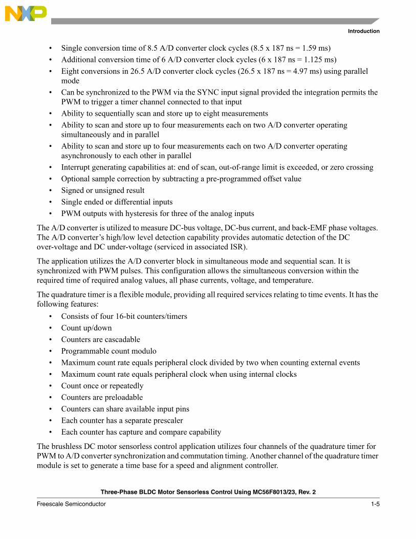
• Single conversion time of 8.5 A/D converter clock cycles (8.5 x 187 ns = 1.59 ms)• Additional conversion time of 6 A/D converter clock cycles (6 x 187 ns = 1.125 ms)• Eight conversions in 26.5 A/D converter clock cycles (26.5 x 187 ns = 4.97 ms) using parallel
mode• Can be synchronized to the PWM via the SYNC input signal provided the integration permits the
PWM to trigger a timer channel connected to that input• Ability to sequentially scan and store up to eight measurements• Ability to scan and store up to four measurements each on two A/D converter operating
simultaneously and in parallel• Ability to scan and store up to four measurements each on two A/D converter operating
asynchronously to each other in parallel• Interrupt generating capabilities at: end of scan, out-of-range limit is exceeded, or zero crossing• Optional sample correction by subtracting a pre-programmed offset value• Signed or unsigned result• Single ended or differential inputs• PWM outputs with hysteresis for three of the analog inputs
The A/D converter is utilized to measure DC-bus voltage, DC-bus current, and back-EMF phase voltages. The A/D converter’s high/low level detection capability provides automatic detection of the DC over-voltage and DC under-voltage (serviced in associated ISR).
The application utilizes the A/D converter block in simultaneous mode and sequential scan. It is synchronized with PWM pulses. This configuration allows the simultaneous conversion within the required time of required analog values, all phase currents, voltage, and temperature.
The quadrature timer is a flexible module, providing all required services relating to time events. It has the following features:
• Consists of four 16-bit counters/timers• Count up/down• Counters are cascadable• Programmable count modulo• Maximum count rate equals peripheral clock divided by two when counting external events• Maximum count rate equals peripheral clock when using internal clocks• Count once or repeatedly• Counters are preloadable• Counters can share available input pins• Each counter has a separate prescaler• Each counter has capture and compare capability
The brushless DC motor sensorless control application utilizes four channels of the quadrature timer for PWM to A/D converter synchronization and commutation timing. Another channel of the quadrature timer module is set to generate a time base for a speed and alignment controller.

Introduction
Three-Phase BLDC Motor Sensorless Control Using MC56F8013/23, Rev. 2
1-6 Freescale Semiconductor
Three-Phase BLDC Motor Sensorless Control Using MC56F8013/23, Rev. 2
Freescale Semiconductor 2-1
Chapter 2 Control
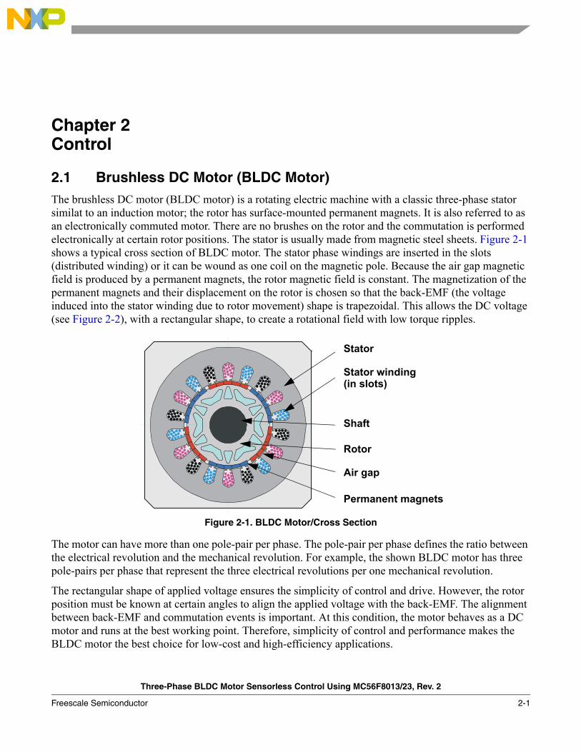
2.1 Brushless DC Motor (BLDC Motor) The brushless DC motor (BLDC motor) is a rotating electric machine with a classic three-phase stator similat to an induction motor; the rotor has surface-mounted permanent magnets. It is also referred to as an electronically commuted motor. There are no brushes on the rotor and the commutation is performed electronically at certain rotor positions. The stator is usually made from magnetic steel sheets. Figure 2-1 shows a typical cross section of BLDC motor. The stator phase windings are inserted in the slots (distributed winding) or it can be wound as one coil on the magnetic pole. Because the air gap magnetic field is produced by a permanent magnets, the rotor magnetic field is constant. The magnetization of the permanent magnets and their displacement on the rotor is chosen so that the back-EMF (the voltage induced into the stator winding due to rotor movement) shape is trapezoidal. This allows the DC voltage (see Figure 2-2), with a rectangular shape, to create a rotational field with low torque ripples.
Figure 2-1. BLDC Motor/Cross Section
The motor can have more than one pole-pair per phase. The pole-pair per phase defines the ratio between the electrical revolution and the mechanical revolution. For example, the shown BLDC motor has three pole-pairs per phase that represent the three electrical revolutions per one mechanical revolution.
The rectangular shape of applied voltage ensures the simplicity of control and drive. However, the rotor position must be known at certain angles to align the applied voltage with the back-EMF. The alignment between back-EMF and commutation events is important. At this condition, the motor behaves as a DC motor and runs at the best working point. Therefore, simplicity of control and performance makes the BLDC motor the best choice for low-cost and high-efficiency applications.
Stator
Stator winding(in slots)
Shaft
Rotor
Air gap
Permanent magnets

Control
Three-Phase BLDC Motor Sensorless Control Using MC56F8013/23, Rev. 2
2-2 Freescale Semiconductor
Figure 2-2. Three Phase Voltage System for BLDC Motor
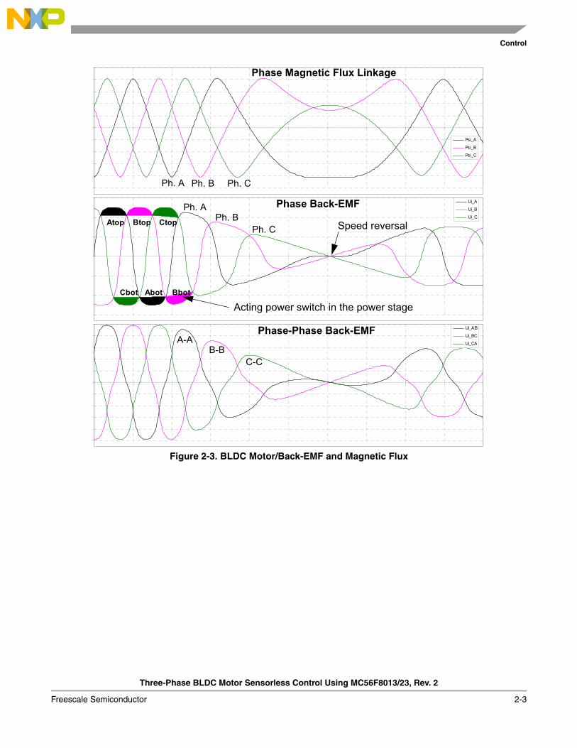
Figure 2-3 shows the number of waveforms, the magnetic flux linkage, the phase back-EMF voltage, and the phase-to-phase back-EMF voltage. The magnetic flux linkage was measured by calculating the integration phase back-EMF voltage, which was measured on the non-fed motor terminals of the BLDC motor. As can be seen, the shape of the back-EMF is approximately trapezoidal and the amplitude is a function of the actual speed. During the speed reversal, the amplitude is changed and its sign and the phase sequence change too.
The filled areas in the tops of the phase back-EMF voltage waveforms indicate the intervals where the particular phase power stage commutations are conducted. As can be seen, the power switches are cyclically commutated through the six steps. The crossing points of the phase back-EMF voltages represent the natural commutation points. At the normal operation, the commutation is performed here. Some control techniques lead the commutation by a defined angle to control the drive above the PWM voltage control.
Phase A
Phase B
Phase C
30° 60° 90° 120° 150° 180° 210° 240° 270° 300° 330° 0° 30°
Electrical angle
Voltage
120° 120°
Control
Three-Phase BLDC Motor Sensorless Control Using MC56F8013/23, Rev. 2
Freescale Semiconductor 2-3
Figure 2-3. BLDC Motor/Back-EMF and Magnetic Flux
Psi_A
Psi_B
Psi_C
Ui_A
Ui_B
Ui_C
Ui_AB
Ui_BC
Ui_CA
Atop Btop Ctop
Cbot Abot Bbot
Phase Magnetic Flux Linkage
Ph. A Ph. B Ph. C
Phase Back-EMF
Phase-Phase Back-EMF
Ph. A Ph. B
Ph. C
A-A B-B
C-C
Acting power switch in the power stage
Speed reversal

Control
Three-Phase BLDC Motor Sensorless Control Using MC56F8013/23, Rev. 2
2-4 Freescale Semiconductor
2.2 Power StageThe voltage for a three-phase BLDC motor is provided by a typical three-phase power stage. The three-phase power stage is controlled by the DSC’s on-chip PWM module that creates the desired switch control signals. A three-phase BLDC motor and power stage is shown in Figure 2-4.
Figure 2-4. 3 Phase BLDC Motor Power Stage
Q1
PWM_Q5
Q6Q4
C1
Phase_C
PWM_Q1
PWM_Q4
PWM_Q3
Phase_B
GND
Q2
UDCB
PWM_Q2
Phase_A
Q3
PWM_Q6
Q5
Control
Three-Phase BLDC Motor Sensorless Control Using MC56F8013/23, Rev. 2
Freescale Semiconductor 2-5
2.3 Mathematical Description of Brushless DC Motor
2.3.1 Power Stage – Motor System Model
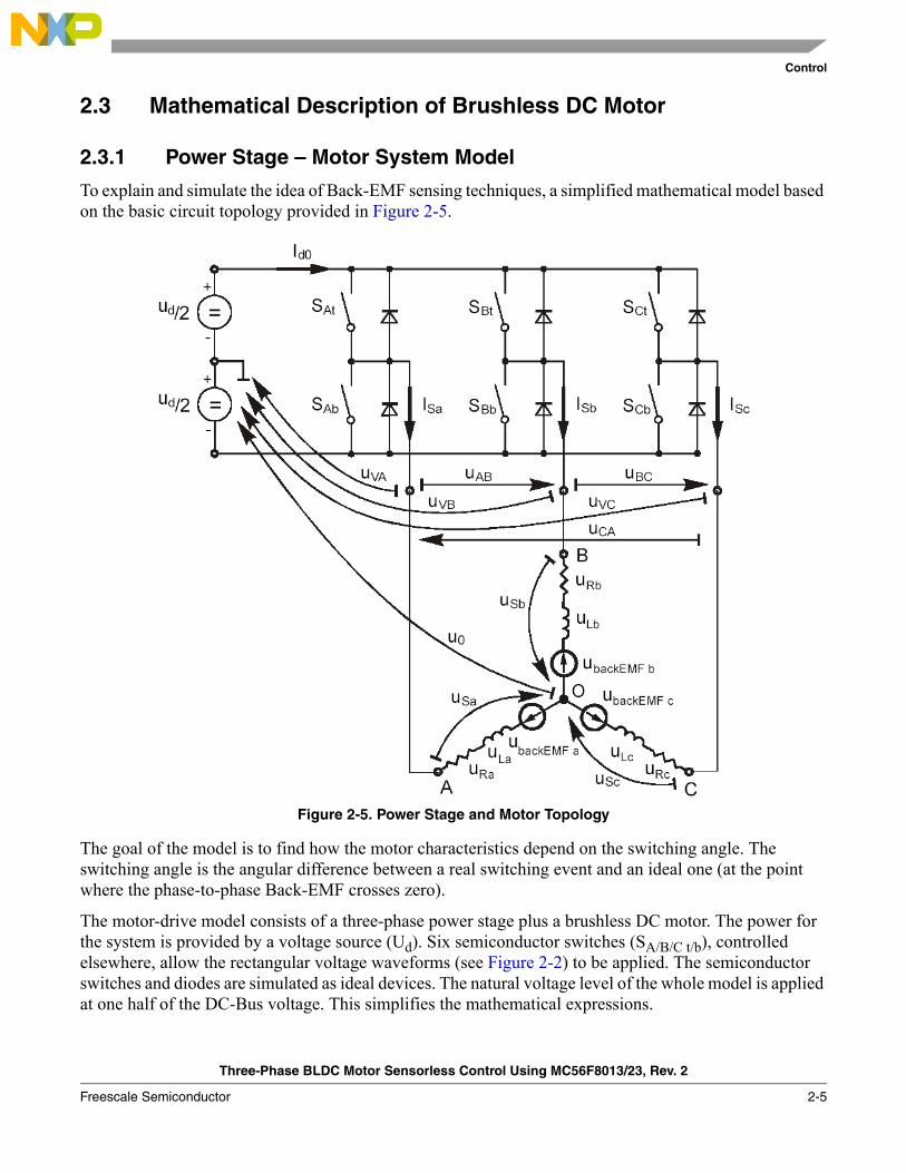
To explain and simulate the idea of Back-EMF sensing techniques, a simplified mathematical model based on the basic circuit topology provided in Figure 2-5.
Figure 2-5. Power Stage and Motor Topology
The goal of the model is to find how the motor characteristics depend on the switching angle. The switching angle is the angular difference between a real switching event and an ideal one (at the point where the phase-to-phase Back-EMF crosses zero).
The motor-drive model consists of a three-phase power stage plus a brushless DC motor. The power for the system is provided by a voltage source (Ud). Six semiconductor switches (SA/B/C t/b), controlled elsewhere, allow the rectangular voltage waveforms (see Figure 2-2) to be applied. The semiconductor switches and diodes are simulated as ideal devices. The natural voltage level of the whole model is applied at one half of the DC-Bus voltage. This simplifies the mathematical expressions.
Control
Three-Phase BLDC Motor Sensorless Control Using MC56F8013/23, Rev. 2
2-6 Freescale Semiconductor
2.3.2 Mathematical Model
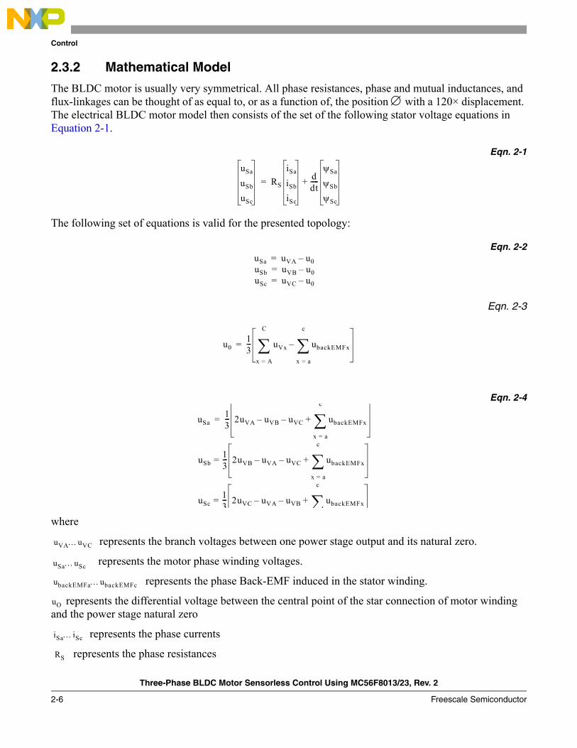
The BLDC motor is usually very symmetrical. All phase resistances, phase and mutual inductances, and flux-linkages can be thought of as equal to, or as a function of, the position ∅ with a 120× displacement. The electrical BLDC motor model then consists of the set of the following stator voltage equations in Equation 2-1.
Eqn. 2-1
The following set of equations is valid for the presented topology:
Eqn. 2-2
Eqn. 2-3
Eqn. 2-4
where
represents the branch voltages between one power stage output and its natural zero.
represents the motor phase winding voltages.
represents the phase Back-EMF induced in the stator winding.
represents the differential voltage between the central point of the star connection of motor winding and the power stage natural zero
represents the phase currents
represents the phase resistances
uSa
uSb
uSc
RS
iSa
iSb
iSc
ddt-----
ψSa
ψSb
ψSc
+=
uSa uVA u0uSb
–uVB u0
uSc
–uVC u0–
===
u013--- uVx ubackEMFx
x a=
c
∑–
x A=
C
∑=
uSa13--- 2uVA uVB– uVC– ubackEMFx
x a=
c
∑+
uSb13--- 2uVB uVA– uVC– ubackEMFx
x a=
c
∑+
uSc13--- 2uVC uVA– uVB– ubackEMFx
c
∑+=
=
=
uVA…uVC
uSa…uSc
ubackEMFa…ubackEMFc
uO
iSa…iSc
RS
Control
Three-Phase BLDC Motor Sensorless Control Using MC56F8013/23, Rev. 2
Freescale Semiconductor 2-7
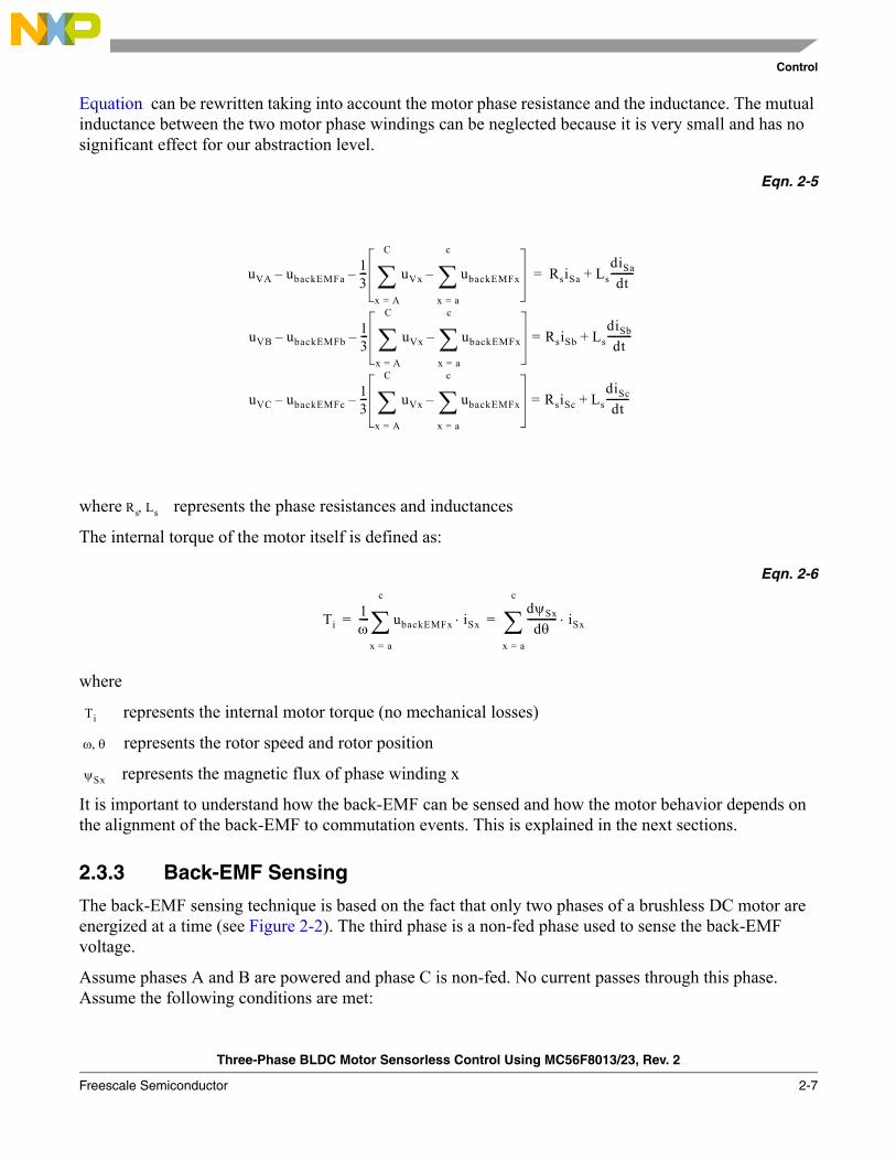
Equation can be rewritten taking into account the motor phase resistance and the inductance. The mutual inductance between the two motor phase windings can be neglected because it is very small and has no significant effect for our abstraction level.
Eqn. 2-5
where represents the phase resistances and inductances
The internal torque of the motor itself is defined as:
Eqn. 2-6
where
represents the internal motor torque (no mechanical losses)
represents the rotor speed and rotor position
represents the magnetic flux of phase winding x
It is important to understand how the back-EMF can be sensed and how the motor behavior depends on the alignment of the back-EMF to commutation events. This is explained in the next sections.
2.3.3 Back-EMF Sensing
The back-EMF sensing technique is based on the fact that only two phases of a brushless DC motor are energized at a time (see Figure 2-2). The third phase is a non-fed phase used to sense the back-EMF voltage.
Assume phases A and B are powered and phase C is non-fed. No current passes through this phase. Assume the following conditions are met:
uVA ubackEMFa– 13--- uVx ubackEMFx
x a=
c
∑–
x A=
C
∑– RsiSa LsdiSa
dt---------
uVB ubackEMFb– 13--- uVx ubackEMFx
x a=
c
∑–
x A=
C
∑– RsiSb LsdiSb
dt----------
uVC ubackEMFc– 13--- uVx ubackEMFx
x a=
c
∑–
x A=
C
∑– RsiSc LsdiSc
dt---------+=
+=
+=
Rs Ls,
Ti1ω---- ubackEMFx iSx⋅
x a=
c
∑dψSx
dθ------------ iSx⋅
x a=
c
∑= =
Ti
ω θ,
ψSx

Control
Three-Phase BLDC Motor Sensorless Control Using MC56F8013/23, Rev. 2
2-8 Freescale Semiconductor
Eqn. 2-7
The branch voltage uVC can be calculated when considering the above conditions:
Eqn. 2-8
Figure 2-6 illustrates that the branch voltage of phase C, between the power stage output C and the natural voltage level, can be sensed. Therefore, the back-EMF voltage is obtained and the zero crossing can be recognized.
The general expression can be found by:
Eqn. 2-9
where:
Eqn. 2-10
There are two necessary conditions that must be met:• Top and bottom switch (in diagonal) have to be driven with the same PWM signal • No current is going through the non-fed phase used to sense the Back-EMF
The Figure 2-6 shows branch and motor phase winding voltages during a 0-360°electrical interval. Shaded rectangles designate the validity of Equation 2-9. In other words, the back-EMF voltage can be sensed during designated intervals.
Figure 2-6. Phase Voltage Waveforms
SAb SBt, PWMswitching←
uVA12---ud+−= uVB
12---± ud=,
iSa iSb–= iSc 0= iScd 0=, ,
ubackEMFa ubackEMFb ubackEMFc+ + 0=
uVC32---ubackEMFC=
uVx32---ubackEMFx=
x A B C, ,=
Control
Three-Phase BLDC Motor Sensorless Control Using MC56F8013/23, Rev. 2
Freescale Semiconductor 2-9
This solution is more difficult that it appears because the sensed branch voltage also contains some ripples.
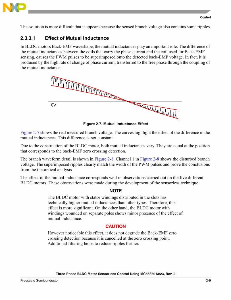
2.3.3.1 Effect of Mutual Inductance
In BLDC motors Back-EMF waveshape, the mutual inductances play an important role. The difference of the mutual inductances between the coils that carry the phase current and the coil used for Back-EMF sensing, causes the PWM pulses to be superimposed onto the detected back-EMF voltage. In fact, it is produced by the high rate of change of phase current, transferred to the free phase through the coupling of the mutual inductance.
Figure 2-7. Mutual Inductance Effect
Figure 2-7 shows the real measured branch voltage. The curves highlight the effect of the difference in the mutual inductances. This difference is not constant.
Due to the construction of the BLDC motor, both mutual inductances vary. They are equal at the position that corresponds to the back-EMF zero crossing detection.
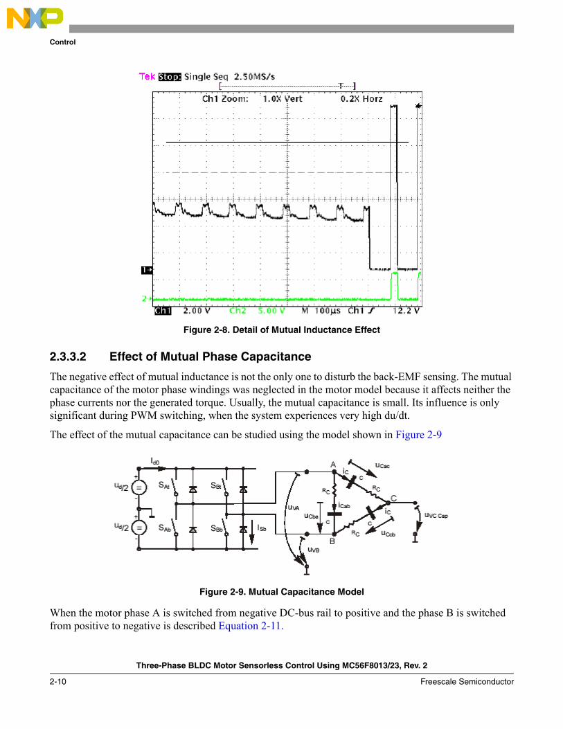
The branch waveform detail is shown in Figure 2-8. Channel 1 in Figure 2-8 shows the disturbed branch voltage. The superimposed ripples clearly match the width of the PWM pulses and prove the conclusions from the theoretical analysis.
The effect of the mutual inductance corresponds well in observations carried out on the five different BLDC motors. These observations were made during the development of the sensorless technique.
NOTEThe BLDC motor with stator windings distributed in the slots has technically higher mutual inductances than other types. Therefore, this effect is more significant. On the other hand, the BLDC motor with windings wounded on separate poles shows minor presence of the effect of mutual inductance.
CAUTIONHowever noticeable this effect, it does not degrade the Back-EMF zero crossing detection because it is cancelled at the zero crossing point. Additional filtering helps to reduce ripples further.
Control
Three-Phase BLDC Motor Sensorless Control Using MC56F8013/23, Rev. 2
2-10 Freescale Semiconductor
Figure 2-8. Detail of Mutual Inductance Effect
2.3.3.2 Effect of Mutual Phase Capacitance
The negative effect of mutual inductance is not the only one to disturb the back-EMF sensing. The mutual capacitance of the motor phase windings was neglected in the motor model because it affects neither the phase currents nor the generated torque. Usually, the mutual capacitance is small. Its influence is only significant during PWM switching, when the system experiences very high du/dt.
The effect of the mutual capacitance can be studied using the model shown in Figure 2-9
Figure 2-9. Mutual Capacitance Model
When the motor phase A is switched from negative DC-bus rail to positive and the phase B is switched from positive to negative is described Equation 2-11.
Control
Three-Phase BLDC Motor Sensorless Control Using MC56F8013/23, Rev. 2
Freescale Semiconductor 2-11
Eqn. 2-11
The voltage that disturbs the Back-EMF sensing, utilizing the free (not powered) motor phase C, can be calculated based on the equation:
Eqn. 2-12
The final expression for disturbing voltage can be found as follows:
Eqn. 2-13
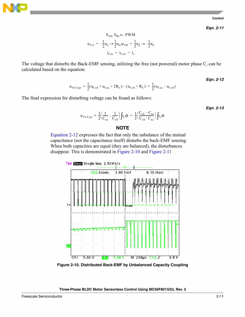
NOTEEquation 2-12 expresses the fact that only the unbalance of the mutual capacitance (not the capacitance itself) disturbs the back-EMF sensing. When both capacities are equal (they are balanced), the disturbances disappear. This is demonstrated in Figure 2-10 and Figure 2-11
Figure 2-10. Distributed Back-EMF by Unbalanced Capacity Coupling
SAb SBt PWM
uVA
←,
12---ud– 1
2---ud uVB,→ 1
2---ud
12---ud
iCac
–→
iCcb ic
= =
= =
uVCCap12--- uCcb uCac 2RC+ +( ) uCcb RC+( )– 1
2--- uCac uCcb–( )= =
uVCCap12--- 1
Cac-------- 1
Ccb--------–⎝ ⎠
⎛ ⎞ ic td∫ 12---
Ccb Cac–Ccb Cac⋅----------------------⎝ ⎠
⎛ ⎞ ic td∫= =
Control
Three-Phase BLDC Motor Sensorless Control Using MC56F8013/23, Rev. 2
2-12 Freescale Semiconductor
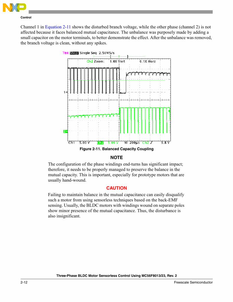
Channel 1 in Equation 2-11 shows the disturbed branch voltage, while the other phase (channel 2) is not affected because it faces balanced mutual capacitance. The unbalance was purposely made by adding a small capacitor on the motor terminals, to better demonstrate the effect. After the unbalance was removed, the branch voltage is clean, without any spikes.
Figure 2-11. Balanced Capacity Coupling
NOTEThe configuration of the phase windings end-turns has significant impact; therefore, it needs to be properly managed to preserve the balance in the mutual capacity. This is important, especially for prototype motors that are usually hand-wound.
CAUTIONFailing to maintain balance in the mutual capacitance can easily disqualify such a motor from using sensorless techniques based on the back-EMF sensing. Usually, the BLDC motors with windings wound on separate poles show minor presence of the mutual capacitance. Thus, the disturbance is also insignificant.

Three-Phase BLDC Motor Sensorless Control Using MC56F8013/23, Rev. 2
Freescale Semiconductor 3-1
Chapter 3 Hardware
3.1 Hardware ImplementationThe BLDC sensorless application runs on Freescale’s MC56F8013/23 Evaluation Board and on many power stage-motor configurations. For simplification, it can be better to split power stages and motors, because both motors can be used with both power stages.
The application can run on the following power stages:• EVM33395 Evaluation Motor Board• Micro Power Board
The application can run with the following motors:• IB23811 Motor (produced by MCG)• N2311 Low Voltage Motor (produced by Pittman)
One of the power stages and one of the motors can be selected to create an application setup and can run using MC56F8013/23 Controller Board.
More information for running the application on different power stages and motors is given in Chapter 7, “Tuning”.
NOTETo select the desired power stage board and motor in application software, use the #define directives in bldcadczcconfig.h file.
NOTEAlthough this reference design demonstatrates the application using low voltage power stages, it can be adapted to high voltage power stages and applications as well.

Hardware
Three-Phase BLDC Motor Sensorless Control Using MC56F8013/23, Rev. 2
3-2 Freescale Semiconductor
3.1.1 Hardware Implementation with EVM33395 Evaluation Motor Board
Figure 3-1. Hardware Diagram with 33395EVM Board
MC56F8013/23 Controller Board
U1
33395EVM Board
U2
J4
J6
JP4 J3
J8 J5 J7
40-pin flat cable J1
RS232 to PCSerial Port
JTAG Comm. Conv.
JTAG to PC Parallel Port
14-pin flat cable
BLDC Motor
J1
+
+12V
0V
-
M1
U3
IB23811 or N2311

Hardware
Three-Phase BLDC Motor Sensorless Control Using MC56F8013/23, Rev. 2
Freescale Semiconductor 3-3
3.1.2 Hardware Implementation with Micro Power Board
Figure 3-2. Hardware Diagram with Micro Power Board
3.2 Component Descriptions
3.2.1 MC56F8013/23 Controller Board
The MC56F8013/23 Controller Board is used to demonstrate the abilities of the MC56F8013 and MC56F8023 digital signal microcontrollers. It provides a hardware tool allowing the development of motor control applications.
The MC56F8013/23 Controller Board can be populated with MC56F8013 or MC56F8023 parts. PCBs marked with numbers 00216A01 and 00216A02 are populated with the MC56F8013 device. PCBs marked with numbers 00216B02 are populated with the MC56F8023 device.
The controller board includes peripheral expansion connectors and some peripheral expansions, which are for signal monitoring and user feature expandability.
Board has the following features:• MC56F8013 or MC56F8023 16-bit +3.3V Digital Signal Controller operating at 32 MHz• Internal oscillator• Joint test action group (JTAG) port interface connector for an external debug host target interface
MC56F8013/23 Controller Board
U1
Micro Power Stage Board
U2
J4
J6
J2
J4
40-pin flat cable
J1
RS232 to PC Serial Port
JTAG Comm. Conv.
JTAG to PC Parallel Port
14-pin flat cable
BLDC Motor
J1
+12V / 0V
M1
U3
IB23811 or N2311
J12 J3
+12V / 0V

Hardware
Three-Phase BLDC Motor Sensorless Control Using MC56F8013/23, Rev. 2
3-4 Freescale Semiconductor
• RS-232 interface— Galvanic isolation— Single wire/bi-wire communication option— Maximum communication speed is limited to 9600 Bd
• SPI connector• 64-kBit serial EEPROM (optional)• UNI-3 motor Interface • Encoder/Hall-Effect interface• Configurable A/D converter pin connections• DC-Bus over-voltage sensing and over-current sensing• Phase back-EMF sensing• Zero crossing detection• Tacho-generator interface for digital/analog sensing• Push-Buttons (reset, up, down)• Run/Stop toggle switch• Indication LEDs (Power ON, Fault, User, PWM)• On-board power regulation from an external 12 V DC supplied power input• All GPIOA, GPIOB, and GPIOC pins available via header pins
Hardware
Three-Phase BLDC Motor Sensorless Control Using MC56F8013/23, Rev. 2
Freescale Semiconductor 3-5
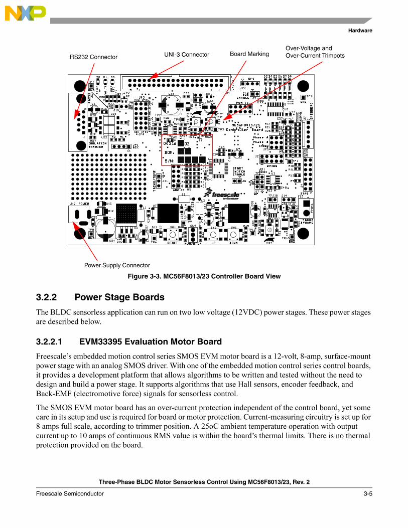
Figure 3-3. MC56F8013/23 Controller Board View
3.2.2 Power Stage Boards
The BLDC sensorless application can run on two low voltage (12VDC) power stages. These power stages are described below.
3.2.2.1 EVM33395 Evaluation Motor Board
Freescale’s embedded motion control series SMOS EVM motor board is a 12-volt, 8-amp, surface-mount power stage with an analog SMOS driver. With one of the embedded motion control series control boards, it provides a development platform that allows algorithms to be written and tested without the need to design and build a power stage. It supports algorithms that use Hall sensors, encoder feedback, and Back-EMF (electromotive force) signals for sensorless control.
The SMOS EVM motor board has an over-current protection independent of the control board, yet some care in its setup and use is required for board or motor protection. Current-measuring circuitry is set up for 8 amps full scale, according to trimmer position. A 25oC ambient temperature operation with output current up to 10 amps of continuous RMS value is within the board’s thermal limits. There is no thermal protection provided on the board.
UNI-3 ConnectorRS232 Connector
Over-Voltage and Over-Current TrimpotsBoard Marking
Power Supply Connector

Hardware
Three-Phase BLDC Motor Sensorless Control Using MC56F8013/23, Rev. 2
3-6 Freescale Semiconductor
Figure 3-4. EVM33395 Evalution Motor Board View
Input connections are made via a 40-pin ribbon cable connector J1. Power connections to the motor are made on one of the output connectors J2 or J4 or FASTON type (J5 J7 J8). Phase A (J8), phase B (J7), and phase C (J5) are labeled on the board. The phase pin order for all three connector types is identical. Power requirements are met by a single external 12-VDC power supply. Two connectors, labeled J3 and JP4, are provided for the 12-volt power supply; they are located on the front edge of the board. Power is supplied to one or the other, but not both.
UNI-3 CONNECTOR
MOTOR CONNECTORS
POWER SUPPLY CONNECTORS
CURRENT TRIMMER

Hardware
Three-Phase BLDC Motor Sensorless Control Using MC56F8013/23, Rev. 2
Freescale Semiconductor 3-7
3.2.2.2 Micro Power Board
Freescale’s embedded motion control series, three-phase micro power stage, is a 12-volt, 6-amp, surface-mount power stage. With one of the embedded motion control series control boards, it provides a software development platform that allows algorithms to be written and tested without the need to design and build a power stage. It supports algorithms that use Hall sensors and back-EMF (electromotive force) signals for sensorless control.
The three-phase micro power stage does not have any over-current protection independent of the control board, so some care in its setup and use is required if a lower impedance motor is used. The power output stage withstands a full-stall condition without the need for over-current protection with the motor supplied in the kit. Current measuring circuitry is set up for 8.25 amps full scale. A 25oC ambient operation at up to 6A continuous RMS output current is within the board’s thermal limits.
Table 3-1. Electrical Characteristics of EVM33395 Board
Characteristic Symbol Min Typ Max Units
Power Supply Voltage VDC 10.2 12 16 V
Quiescent Current ICC — 70 — mA
High State Logic 1 Input Voltage VIH 2.4 3.3 or 5 7 V
Low State Logic 0 Input Voltage VIL — < 0.4 0.8 V
Input Resistance RIn — 10 — kΩ
Analog Output Range VOut 0 — 3.3 V
Phase Current Sense Voltage ISense — 172 — mV/A
Bus Voltage Sense Voltage VBus — 206 — mV/V
Power MOSFET On Resistance RDS(On) — 10 16 mΩ
RMS Output Current IM — — 10 A
Total Power Dissipation Pdiss — — 18 W

Hardware
Three-Phase BLDC Motor Sensorless Control Using MC56F8013/23, Rev. 2
3-8 Freescale Semiconductor
Figure 3-5. Micro Power Stage View
Input connections are made via 40-pin ribbon cable connector J1. Power connections to the motor are made on output connector J4. Phase A, B, and C are labeled on the board. Power requirements are met with a single external 12 V, 4 A power supply. Two connectors, labeled J2 and J3, are provided for the 12 VDC power supply. While the former is used for 12 VDC input, the latter is used for 12 VDC output for powering the controller board. Both are located in a corner of the board.
Table 3-2. Electrical Characteristics of Micro Power Board
Characteristic Symbol Min Typ Max Units
Power Supply Voltage VDC 10 12 16 V
Quiescent Current ICC — 18 — mA
Min Logic 1 Input Voltage VIH 2.4 — — V
Max Logic 0 Input Voltage VIL — — 0.8 V
Input Resistance RIn — 10 — kΩ
Analog Output Range VOut 0 — 3.3 V
Bus Current Sense Voltage ISense — 200 — mV/A
Bus Voltage Sense Voltage VBus — 202 — mV/V
Power MOSFET On Resistance RDS(On) — 40 — mΩ
Continous Output Current ID — — 6 A
Pulsed Output Current IDM — — 15 A
Total Power Dissipation Pdiss — — 2.4 W
Deadtime toff 400 — — ns
UNI-3 CONNECTOR
MOTOR CONNECTOR
POWER SUPPLY CONNECTORS
Hardware
Three-Phase BLDC Motor Sensorless Control Using MC56F8013/23, Rev. 2
Freescale Semiconductor 3-9
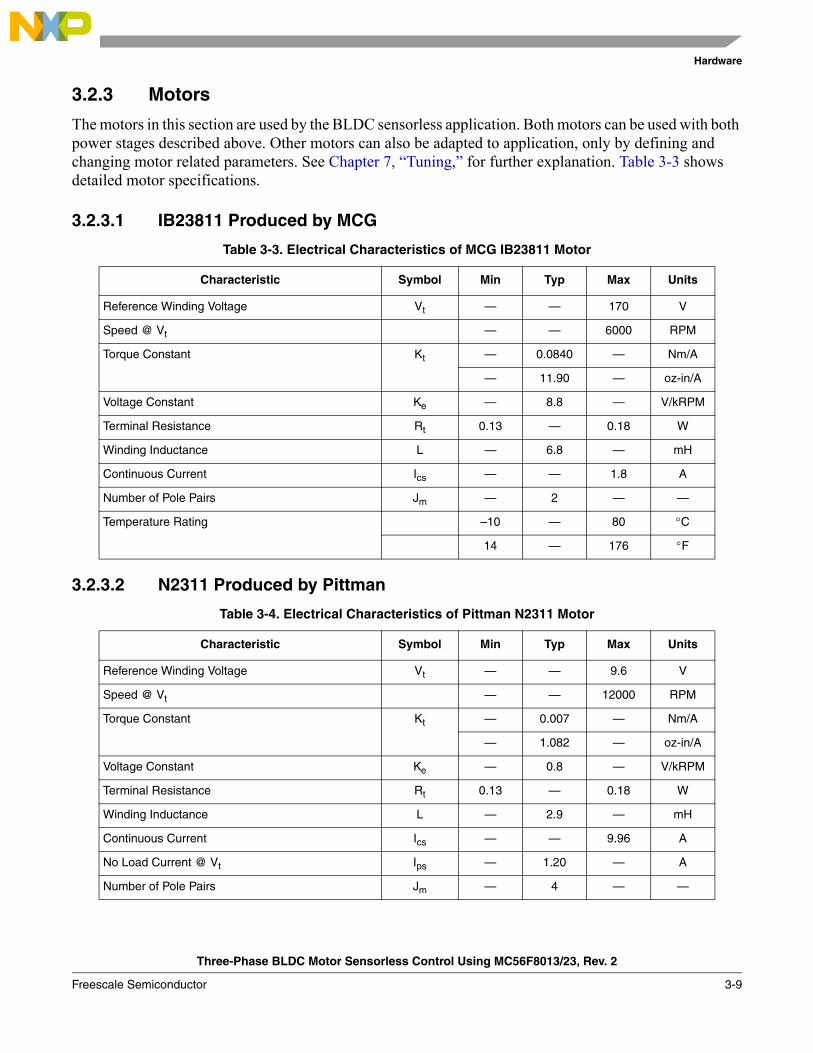
3.2.3 Motors
The motors in this section are used by the BLDC sensorless application. Both motors can be used with both power stages described above. Other motors can also be adapted to application, only by defining and changing motor related parameters. See Chapter 7, “Tuning,” for further explanation. Table 3-3 shows detailed motor specifications.
3.2.3.1 IB23811 Produced by MCG
3.2.3.2 N2311 Produced by Pittman
Table 3-3. Electrical Characteristics of MCG IB23811 Motor
Characteristic Symbol Min Typ Max Units
Reference Winding Voltage Vt — — 170 V
Speed @ Vt — — 6000 RPM
Torque Constant Kt — 0.0840 — Nm/A
— 11.90 — oz-in/A
Voltage Constant Ke — 8.8 — V/kRPM
Terminal Resistance Rt 0.13 — 0.18 W
Winding Inductance L — 6.8 — mH
Continuous Current Ics — — 1.8 A
Number of Pole Pairs Jm — 2 — —
Temperature Rating –10 — 80 °C
14 — 176 °F
Table 3-4. Electrical Characteristics of Pittman N2311 Motor
Characteristic Symbol Min Typ Max Units
Reference Winding Voltage Vt — — 9.6 V
Speed @ Vt — — 12000 RPM
Torque Constant Kt — 0.007 — Nm/A
— 1.082 — oz-in/A
Voltage Constant Ke — 0.8 — V/kRPM
Terminal Resistance Rt 0.13 — 0.18 W
Winding Inductance L — 2.9 — mH
Continuous Current Ics — — 9.96 A
No Load Current @ Vt Ips — 1.20 — A
Number of Pole Pairs Jm — 4 — —

Hardware
Three-Phase BLDC Motor Sensorless Control Using MC56F8013/23, Rev. 2
3-10 Freescale Semiconductor
Temperature Rating –10 — 80 °C
14 — 176 °F
Table 3-4. Electrical Characteristics of Pittman N2311 Motor

Three-Phase BLDC Motor Sensorless Control Using MC56F8013/23, Rev. 2
Freescale Semiconductor 4-1
Chapter 4 System
4.1 System SpecificationThe motor control system is designed to drive a three-phase brushless DC motor (BLDC motor) in a speed closed-loop. The application meets the following performance specifications:
• Sensorless brushless DC motor control by back-EMF sensing• Targeted for MC56F8013 and MC56F8023 devices• Running on a low-voltage (12 V) three-phase brushless DC motor control development platform• Control technique incorporates:
— Sensorless control with speed closed-loop at run and current closed loop at alignment— Using A/D converter zero cross sensing for sensorless control— Rotation in both directions— Motoring mode— Start from any motor position with rotor alignment— Automatic calibration of phase back-EMF measurements— Manual interface (run/stop switch, up/down push button control)— FreeMaster software control interface (motor run/stop, speed set-up, alarm indicators)— FreeMaster software remote monitor — DC over-voltage, DC under-voltage, and DC over-current alarms— Adjustable DC-bus current limitation with software
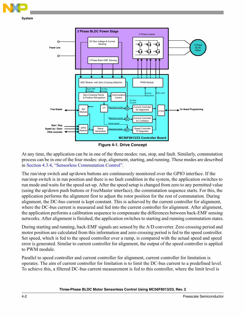
4.2 Sensorless Drive ConceptFigure 4-1 shows the chosen system concept.
System
Three-Phase BLDC Motor Sensorless Control Using MC56F8013/23, Rev. 2
4-2 Freescale Semiconductor
Figure 4-1. Drive Concept
At any time, the application can be in one of the three modes: run, stop, and fault. Similarly, commutation process can be in one of the four modes: stop, alignment, starting, and running. These modes are described in Section 4.3.4, “Sensorless Commutation Control”.
The run/stop switch and up/down buttons are continuously monitored over the GPIO interface. If the run/stop switch is in run position and there is no fault condition in the system, the application switches to run mode and waits for the speed set-up. After the speed setup is changed from zero to any permitted value (using the up/down push buttons or FreeMaster interface), the commutation sequence starts. For this, the application performs the alignment first to adjust the rotor position for the rest of commutation. During alignment, the DC-bus current is kept constant. This is achieved by the current controller for alignment, where the DC-bus current is measured and fed into the current controller for alignment. After alignment, the application performs a calibration sequence to compensate the differences between back-EMF sensing networks. After alignment is finished, the application switches to starting and running commutation states.
During starting and running, back-EMF signals are sensed by the A/D converter. Zero crossing period and motor position are calculated from this information and zero crossing period is fed to the speed controller. Set speed, which is fed to the speed controller over a ramp, is compared with the actual speed and speed error is generated. Similar to current controller for alignment, the output of the speed controller is applied to PWM module.
Parallel to speed controller and current controller for alignment, current controller for limitation is operates. The aim of current controller for limitation is to limit the DC-bus current to a predefined level. To achieve this, a filtered DC-bus current measurement is fed to this controller, where the limit level is
DC Bus Voltage & Current Sensing
3 Phase Back EMF Sensing
3 Phase Inverter3 Phase BLDC Power Stage
PWM ModuleADC Module with Zero Crossing Detection
Power Line3 Phase BLDC Motor
GPIO Module
SCI Module
Free Master
Start / StopSpeed Up / Down
Other purposesRamp
GenerationSpeed Controller
PI Regulator
Zero Crossing Period & Position Recognition
Commutation Control
1/T
MC56F8013/23 Controller Board
JTAGOn Board Programming
Duty cycle
Actual speed
Comm. sequence
Required speed + -
Current Controller for Limitation
Current Controller for Alignment
DC Bus Current
DC Bus Voltage
Back EMF Voltages
Maximum current
Alignment current
+
+
-
-
System
Three-Phase BLDC Motor Sensorless Control Using MC56F8013/23, Rev. 2
Freescale Semiconductor 4-3
defined by software setpoint. The PWM duty cyle is only decreased by this controller if the DC-bus current level is higher than the set level.
On the background, the DC-bus voltage is continuously measured for alarm recognition and for updating back-EMF detection offset.
DC over-voltage and DC under-voltage faults are detected by the A/D converter, where DC over-current fault is detected by the PWM Fault input.
After a fault condition occurs, the application switches to fault state, stops the motor, and waits for the fault reset over FreeMaster interface or over run/stop switch. Beyond this, FreeMaster interface enables to monitor and adjust all system variables.
4.3 System Blocks Concept
4.3.1 PWM Voltage Generation for Brushless DC Motor
A three-phase voltage system as described needs to be created to run the BLDC motor. It is provided by three-phase power stage with six power switches (IGBTs or MOSFETs) controlled by the DSC’s on-chip PWM module.
When generating PWM signals for BLDC motor control application, bottom and top power switches of the non-fed phase must be switched off. (See Figure 4-2 and Figure 4-3)
For BLDC motor control application, PWM signals can be created in two ways: independent PWM mode and complementary PWM Mode. Because of the MC56F8000 family PWM module and its mask/swap feature, these modes are available with minor software overhead.
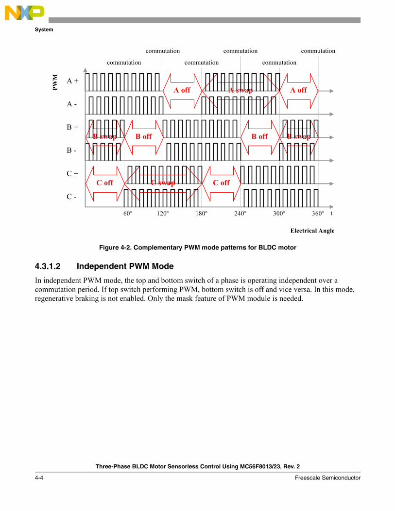
4.3.1.1 Complementary PWM Mode
In complementary PWM mode, the top and bottom switch of a phase is operating complementary. This mode enables regenerative braking, where DC-bus voltage may increase during deceleration or stop. In this mode, swap and mask features of PWM module are used together.
System
Three-Phase BLDC Motor Sensorless Control Using MC56F8013/23, Rev. 2
4-4 Freescale Semiconductor
Figure 4-2. Complementary PWM mode patterns for BLDC motor
4.3.1.2 Independent PWM Mode
In independent PWM mode, the top and bottom switch of a phase is operating independent over a commutation period. If top switch performing PWM, bottom switch is off and vice versa. In this mode, regenerative braking is not enabled. Only the mask feature of PWM module is needed.
B swap B swap
A swapA +
A -
B +
B -
C +
C -
t 60°
A off A off
B off B off
C off C off
120° 180° 240° 300° 360°
commutation commutation commutation
commutation commutation commutation
Electrical Angle
PWM
C swap

System
Three-Phase BLDC Motor Sensorless Control Using MC56F8013/23, Rev. 2
Freescale Semiconductor 4-5
Figure 4-3. Independent PWM mode patterns for BLDC motor
4.3.2 A/D Converter Sampling Mechanism
The power stage PWM switching causes high voltage spike on the phase voltages. This voltage spike is generated on the non-fed because of mutual inductances and mutual capacitor couplings between the motor windings. Non-fed phase branch voltage is then disturbed by PWM switching. Figure 4-4 shows the effect on the non-fed phase because of mutual inductance.
Figure 4-4. Effect of mutual inductance on Back-EMF
A +
A -
B +
B -
C +
C -
t 60°
A off A off
B off B off
C off C off
120° 180° 240° 300° 360°
commutation commutation commutation
commutation commutation commutation
Electrical Angle
PWM
System
Three-Phase BLDC Motor Sensorless Control Using MC56F8013/23, Rev. 2
4-6 Freescale Semiconductor
The non-fed phase branch voltage is disturbed at the PWM switching edges. Therefore, the presented BLDC motor control application synchronizes the back-EMF zero crossing detection with PWM. The A/D conversion of phase branch voltages is triggered in the middle of PWM pulse. Then,the voltage for back-EMF is sensed at the time moments when the non-fed phase branch voltage is already stabilized.
To set the exact moment of sampling, the MC56F8000 family offers the ability to synchronize A/D converter and PWM modules via the SYNC signal. The PWM outputs a synchronization pulse, which is connected as an input to the synchronization module T3 (Quad Timer 3) over system integration module. A high-true pulse occurs for each reload of the PWM, regardless of the state of the LDOK bit. The intended purpose of T3 is to provide a user-selectable delay between the PWM SYNC signal and the updating of the A/D converter values. A conversion process can be initiated by the SYNC input, which is an output of TC3. The delay from the PWM SYNC signal to A/D converter measurement start is updated after every calculation of PWM duty cycle, to ensure that the sample is taken in the middle of the PWM pulses. The time diagram of the automatic synchronization between PWM and A/D converter is shown in Figure 4-5

System
Three-Phase BLDC Motor Sensorless Control Using MC56F8013/23, Rev. 2
Freescale Semiconductor 4-7
Figure 4-5. Time Diagram of PWM and A/D Converter Synchronization
4.3.3 Back-EMF Zero Crossing Sensing
The back-EMF zero crossing is detected by sensing the motors non-fed phase branch voltage (uvi in Section 2.3.3, “Back-EMF Sensing”) and DC-bus voltage ud utilizing the A/D converter. See Chapter 2, “Control”.
The Freescale MC56F8000 family offers an excellent on-chip analog-to-digital converter. Its unique feature set provides an automatic detection of the signal crossing the value contained in the A/D converter offset register.
PWM COUNTER
PWM SYNC
PWM GENERATOR OUTPUTS 0, 1
PWM PINS 0, 1
POWER STAGE VOLTAGE
T3 COUNTER
T3 OUTPUT
ADC CONVERSION
ADC ISR
dead-time dead-time
dead-time
t1
t2
t1
t2
dead-time
System
Three-Phase BLDC Motor Sensorless Control Using MC56F8013/23, Rev. 2
4-8 Freescale Semiconductor
Then, the Back-EMF Zero Crossing can be split into two main tasks:• A/D converter zero crossing checking• A/D converter zero crossing offset setting to follow the variation of the DC-bus voltage
4.3.3.1 A/D Converter Zero Crossing Checking
The zero crossing for position estimation is sensed using the A/D converter.
As stated, the AD convertor has individual A/D covnerter offset registers for each A/D converter channel. The value in the offset register can be subtracted from the A/D conversion output. The final result of the A/D conversion is then two’s compliment data. The other feature associated to the offset registers is the zero crossing interrupt. The zero crossing interrupt is asserted when the A/D converter conversion result changes the sign compared to the previous conversion result. Refer to the manual for detailed information. Therefore, this application utilizes an A/D convernter zero crossing interrupt to get the back-EMF zero crossing event.
4.3.3.2 A/D Converter Zero Crossing Offset Setting
Actually, the zero crossing is detected, if the phase voltage of the non-fed phase changes it sign, when the offset value is set to half of the DC-bus. Therefore, the A/D converter offset register must be set to one half of the DC-bus voltage value. This update must be continuously performed, to reflect the DC-bus voltage variation caused by the ripple of DC-bus voltage. This is valid at the following conditions:
• Motor phases are symmetrical (all three phases have same parameters)• All hardware dividers for the A/D converter of the DC-bus voltage and all three-phase voltages
have equal ratio
In this application, to compensate for the differences between hardware dividers of phase voltage measurements, a calibration sequence is implemented. This calibration is performed only once, after the first Alignment of the motor. During calibration, alignments are performed for each phase and the third phase is measured to obtain the offset value. Ideally, the value read from the third phase must be equal to half of the DC-bus voltage, but because of component tolerances, it can be more or less than that. When the commutation is running, these measured calibration values are multiplied by the measured DC-bus voltage and A/D converter offset registers are updated.
NOTETo enable or disable calibration feature in application software, use the #define directives in bldcadczcconfig.h file.

System
Three-Phase BLDC Motor Sensorless Control Using MC56F8013/23, Rev. 2
Freescale Semiconductor 4-9
Figure 4-6. Calibration
4.3.4 Sensorless Commutation Control
This section presents sensorless BLDC motor commutation with the back-EMF zero crossing technique. To start and run the BLDC motor, the control algorithm has to go through the following states:
• Alignment• Starting (Back-EMF Acquisition)• Running
Figure 4-7 shows the transitions between the states. First, the rotor is aligned to a known position without the position feedback. When the rotor moves, the back-EMF is induced on the non-fed phase and acquired by the A/D converter. As a result, the position is known and can be used to calculate the speed and process the commutation in the running state.
Perform alignment
Alignment time finished?
Calibration coefficient for non-fed phase =
non-fed phase voltage + 0.5
All phases done?
Starting
Yes
Yes
No
No

System
Three-Phase BLDC Motor Sensorless Control Using MC56F8013/23, Rev. 2
4-10 Freescale Semiconductor
Figure 4-7. Commutation Control States
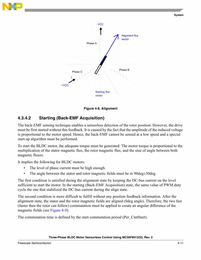
4.3.4.1 Alignment
Before the motor starts, there is a short time (which depends on the motor’s electrical and mechanical time constant) when the rotor position is aligned to a known position by applying PWM signals to only two motor phases (no commutation). The alignment current controller keeps the current within predefined limits. This state is necessary to create a high start-up torque and recognize the rotor position. When the preset time-out expires, this state is finished.
The alignment current controller subroutine (with PI regulator) is called to control the DC-bus current. The subroutine sets the right PWM ratio for the required current. The current is sampled and the current controller is calculated in every PWM cycle.
Figure 4-8 shows the BLDC motor rotor position (with flux vectors during alignment).
Start Motor
Alignment
Alignment time expired?
Starting (Back-EMF Acquisition)
Minimum correct commutations done?
Running
No
Yes
Yes
No
System
Three-Phase BLDC Motor Sensorless Control Using MC56F8013/23, Rev. 2
Freescale Semiconductor 4-11
Figure 4-8. Alignment
4.3.4.2 Starting (Back-EMF Acquisition)
The back-EMF sensing technique enables a sensorless detection of the rotor position. However, the drive must be first started without this feedback. It is caused by the fact that the amplitude of the induced voltage is proportional to the motor speed. Hence, the back-EMF cannot be sensed at a low speed and a special start-up algorithm must be performed.
To start the BLDC motor, the adequate torque must be generated. The motor torque is proportional to the multiplication of the stator magnetic flux, the rotor magnetic flux, and the sine of angle between both magnetic fluxes.
It implies the following for BLDC motors:• The level of phase current must be high enough.• The angle between the stator and rotor magnetic fields must be in 90deg±30deg.
The first condition is satisfied during the alignment state by keeping the DC-bus current on the level sufficient to start the motor. In the starting (Back-EMF Acquisition) state, the same value of PWM duty cycle the one that stabilized the DC-bus current during the align state.
The second condition is more difficult to fulfill without any position feedback information. After the alignment state, the stator and the rotor magnetic fields are aligned (0deg angle). Therefore, the two fast (faster then the rotor can follow) commutation must be applied to create an angular difference of the magnetic fields (see Figure 4-9).
The commutation time is defined by the start commutation period (Per_CmtStart).

System
Three-Phase BLDC Motor Sensorless Control Using MC56F8013/23, Rev. 2
4-12 Freescale Semiconductor
This allows the motor to start with the minimal speed (defined by state when Back-EMF can be sensed) achieved during several commutations while producing the required torque. Back-EMF feedback is locked into the commutation process (see Section 4.3.4.3, “Running”) in advance to ensure that commutations are done so that successive back-EMF zero crossing events are not missed.
After several successive back-EMF zero crossings, the exact commutation times can be calculated. The commutation process is adjusted. The control flow continues to the running state. The BLDC motor is then running with regular feedback and the speed controller can control the motor speed by changing the PWM duty cycle value.
For the starting state, there are three possible zero crossing detection scenarios :• Normal operation: In this case, zero crossing is detected between two commutation periods. This
is the ideal operation.• No zero crossing detected: In this case, no zero crossing is detected between two commutation
periods.• Zero crossing missed: After every commutation period in the application, zero crossing detection
is disabled for a Toff time proportional to the commutation period. After this Toff time is expired, the application checks the polarity of the back-EMF signal. If the polarity is not as expected, the back-EMF shape had the zero cross when the application was waiting for Toff time. In this case, application decides that zero crossing is missed.
System
Three-Phase BLDC Motor Sensorless Control Using MC56F8013/23, Rev. 2
Freescale Semiconductor 4-13
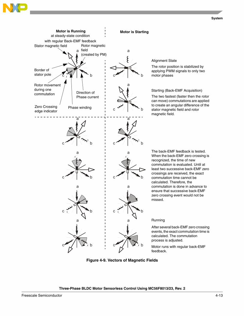
Figure 4-9. Vectors of Magnetic Fields
Border ofstator pole
Stator magnetic field Rotor magnetic
Phase winding
Rotor movement
field
Direction of Phase current
during onecommutation
(created by PM)
Zero Crossingedge indicator
Motor is Runningat steady-state condition
Motor is Starting
Alignment State
Starting (Back-EMF Acquisition)
Running
The rotor position is stabilized by applying PWM signals to only two motor phases
The two fastest (faster then the rotor can move) commutations are applied to create an angular difference of the stator magnetic field and rotor magnetic field.
The back-EMF feedback is tested. When the back-EMF zero crossing is recognized, the time of new commutation is evaluated. Until at least two successive back-EMF zero crossings are received, the exact commutation time cannot be calculated. Therefore, the commutation is done in advance to ensure that successive back-EMF zero crossing event would not be missed.
After several back-EMF zero crossing events, the exact commutation time is calculated. The commutation process is adjusted.
Motor runs with regular back-EMF feedback.
with regular Back-EMF feedback

System
Three-Phase BLDC Motor Sensorless Control Using MC56F8013/23, Rev. 2
4-14 Freescale Semiconductor
Figure 4-10. Back-EMF at Start-Up
Figure 4-10 demonstrates the back-EMF during the start-up. The amplitude of the back-EMF varies according to the rotor speed. During the starting (back-EMF Acquisition) state, the commutation is done in advance. In the running state, the commutation is done at the right moments.
4.3.4.2.1 Commutation Times Calculation
During starting state, next commutation time is calculated in three different ways according to zero cross detection after regular operations.
• Normal operation: During start, zero cross is detected and next commutation time is calculated.
RunningAlign
Back-EMF Zero Crossings
Ideal Commutation Pattern when position is known
Real Commutation Pattern when position is estimated
Phase Back-EMF’s
1’st 2’nd 3’rd 4’rd .................
CTOP
CBOT
ATOP BTOP CTOPBTOP
ABOT BBOT CBOT ABOT
CTOP
CBOT
ATOP BTOPBTOP
ABOT BBOT CBOT ABOT
CTOP
Starting (Back-EMF Acquisition)
System
Three-Phase BLDC Motor Sensorless Control Using MC56F8013/23, Rev. 2
Freescale Semiconductor 4-15
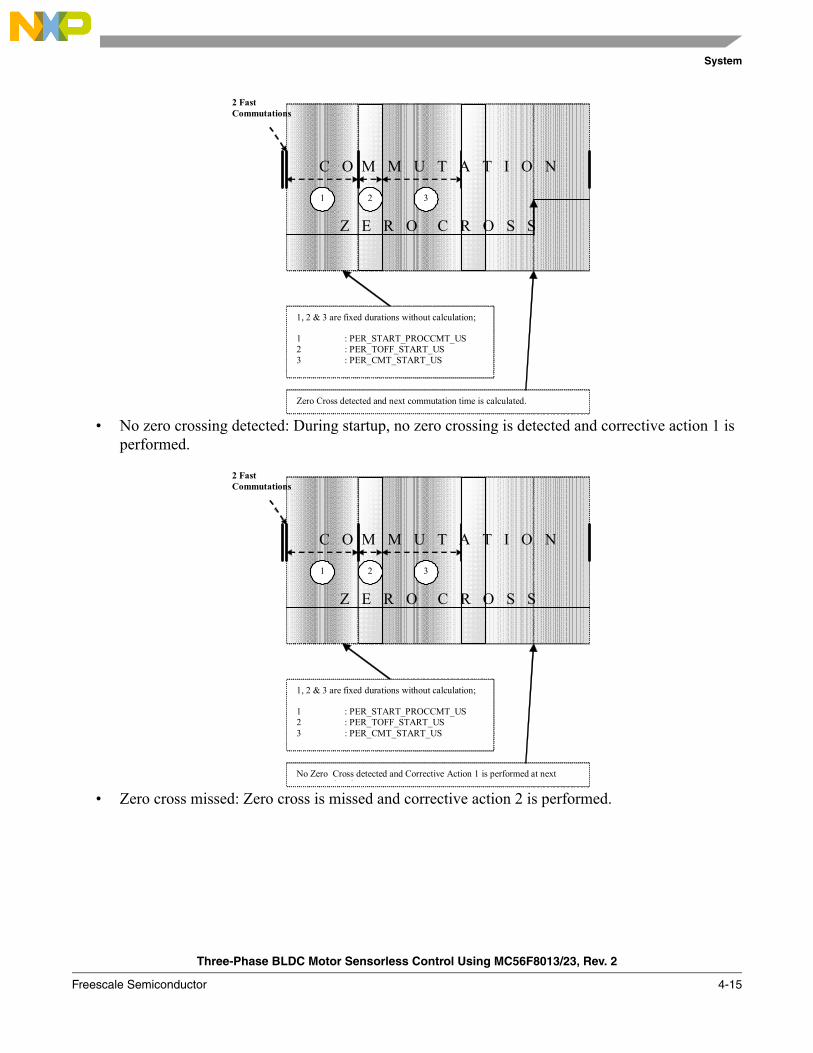
• No zero crossing detected: During startup, no zero crossing is detected and corrective action 1 is performed.
• Zero cross missed: Zero cross is missed and corrective action 2 is performed.
2 Fast Commutations
1, 2 & 3 are fixed durations without calculation; 1 : PER_START_PROCCMT_US 2 : PER_TOFF_START_US 3 : PER_CMT_START_US
C O M M U T A T I O N
Z E R O C R O S S
1 2 3
Zero Cross detected and next commutation time is calculated.
2 Fast Commutations
1, 2 & 3 are fixed durations without calculation; 1 : PER_START_PROCCMT_US 2 : PER_TOFF_START_US 3 : PER_CMT_START_US
C O M M U T A T I O N
Z E R O C R O S S
1 2 3
No Zero Cross detected and Corrective Action 1 is performed at next i i

System
Three-Phase BLDC Motor Sensorless Control Using MC56F8013/23, Rev. 2
4-16 Freescale Semiconductor
4.3.4.3 Running
The commutation process is the series of states ensured when the back-EMF zero crossing is successfully captured. The new commutation time is calculated after back-EMF zero crossing is captured and the commutation is performed. The following processes need to be provided:
• BLDC motor commutation service• Back-EMF zero crossing moment capture service• Computation of commutation times• Handler for interaction between these commutation processes
4.3.4.3.1 Algorithms BLDC Motor Commutation with Zero Crossing Sensing
Diagrams aid in explaining how the commutation works. After commuting the motor phases, a time interval (Per_Toff[n]) is set that allows the shape of the back-EMF to be stabilized. Stabilization is required because the electro-magnetic interference and flyback current in antibody diode can generate glitches that may add to the back-EMF signal. This can cause a misinterpretation of back-EMF zero crossing. Then, the new commutation time (T2[n]) is preset and performed at this time if the back-EMF zero crossing is not captured. If the back-EMF zero crossing is captured before the preset commutation time expires, the exact calculation of the commutation time (T2*[n]) is made based on the captured zero crossing time (T_ZCros[n]). The new commutation is updated at this new time.
2 Fast Commutations
1, 2 & 3 are fixed durations without calculation; 1 : PER_START_PROCCMT_US 2 : PER_TOFF_START_US 3 : PER_CMT_START_US
C O M M U T A T I O N
Z E R O C R O S S
1 2 3
Zero Cross is missed and Corrective Action 2 is performed after Toff time is expired.
System
Three-Phase BLDC Motor Sensorless Control Using MC56F8013/23, Rev. 2
Freescale Semiconductor 4-17
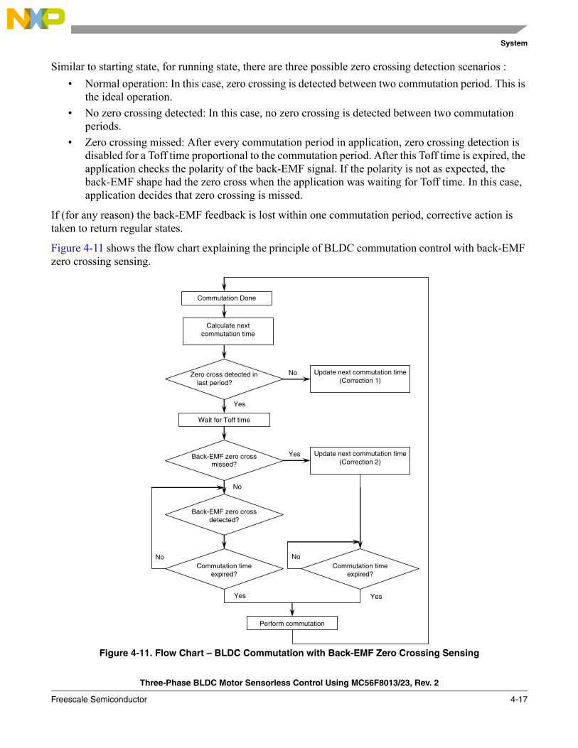
Similar to starting state, for running state, there are three possible zero crossing detection scenarios :• Normal operation: In this case, zero crossing is detected between two commutation period. This is
the ideal operation.• No zero crossing detected: In this case, no zero crossing is detected between two commutation
periods.• Zero crossing missed: After every commutation period in application, zero crossing detection is
disabled for a Toff time proportional to the commutation period. After this Toff time is expired, the application checks the polarity of the back-EMF signal. If the polarity is not as expected, the back-EMF shape had the zero cross when the application was waiting for Toff time. In this case, application decides that zero crossing is missed.
If (for any reason) the back-EMF feedback is lost within one commutation period, corrective action is taken to return regular states.
Figure 4-11 shows the flow chart explaining the principle of BLDC commutation control with back-EMF zero crossing sensing.
Figure 4-11. Flow Chart – BLDC Commutation with Back-EMF Zero Crossing Sensing
Commutation Done
Wait for Toff time
Calculate next commutation time
Back-EMF zero cross missed?
Back-EMF zero cross detected?
Commutation time expired?
Update next commutation time (Correction 1)
Commutation time expired?
Perform commutation
Update next commutation time (Correction 2)
Zero cross detected in last period?
Yes
No
No
Yes
Yes
No
Yes
No

System
Three-Phase BLDC Motor Sensorless Control Using MC56F8013/23, Rev. 2
4-18 Freescale Semiconductor
4.3.4.3.2 Commutation Times Calculation
Similar to start state, the next commutation time is calculated in three different ways during Running according to zero cross detection.
• Normal operation: In this case, zero crossing is properly sensed and all calculations are performed as expected. After zero crossing detection, preset time for commutation is updated.
T_Cmt[n-2] T_Cmt[n] T_Next (cmt)
T_ZCros[n-2] T_ZCros0[n-1]
n-2 n-1 n
Zero Cross detected and next commutation time is calculated as following : Per_ZCros[n] = T_ZCros[n] - T_ZCros[n-1] = T_ZCros[n] - T_ZCros0 Per_ZCrosFlt[n] = (1/2 * Per_ZCros[n] + 1/2 * Per_ZCros0) HlfCmt[n] = 1/2 * Per_ZCrosFlt[n] - Advance_angle = 1/2 * Per_ZCrosFlt[n] - Coef_HlfCmt * Per_ZCrosFlt[n] T_Next*[n] = T_ZCros[n] + HlfCmt[n] The best commutation was get with Advance_angle: 60Deg*1/8 = 7.5Deg which means Coef_HlfCmt = 0.375 at Running state! Per_Toff[n+1] = minimum(Per_ZCrosFlt * Coef_Toff, Max_PerCmtProc) (Coef_Toff = 0.35 at Running state, Max_PerCmtProc = 100!) Per_ZCros0 <-- Per_ZCros[n] T_ZCros0 <-- T_ZCros[n]
Commutation performed and next commutation time is predicted as following : T_Next[n](cmt) = T_Cmt0[n] + Per_CmtPreset[n] = T_Cmt0[n] + Coef_CmtPrecomp * Per_ZCrosFlt[n-1]
If Coef_CmtPrecomp * Per_ZCrosFlt > Max_PerCmt => Result is limited at Max_PerCmt
Per_ZCros0[n]
T_ZCros[n-1]T_ZCros0[n]
T_Cmt[n-1]
C O M M U T A T I O N
T_ZCros[n]
Per_ZCros[n]
Z E R O C R O S S

System
Three-Phase BLDC Motor Sensorless Control Using MC56F8013/23, Rev. 2
Freescale Semiconductor 4-19
• No zero cross detected: In this case, there is no zero cross detected between commutations. Therefore, commutation is performed at preset time and corrective action 1 is performed.
• Zero cross missed: In this case, it has been detected that zero cross is missed. This detection is performed by monitoring the polarity of back-EMF voltage of non-feed phase after Toff time is expired. Corrective action 2 is performed.
T_Cmt[n-2] T_Cmt[n] T_Next (cmt)
T_ZCros[n-2] T_ZCros0[n-1]
n-2 n-1 n
No Zero Cross detected in Commutation period.Corrective Action 1 is performed as following : T_ZCros[n] <-- T_Cmt[n+1] Per_ZCros[n] = T_ZCros[n] - T_ZCros[n-1] = T_ZCros[n] - T_ZCros0 Per_ZCrosFlt[n] = (1/2 * Per_ZCros[n] + 1/2 * Per_ZCros0) HlfCmt[n] = 1/2 * Per_ZCrosFlt[n] - Advance_angle
= 1/2 * Per_ZCrosFlt[n] - Coef_HlfCmt * Per_ZCrosFlt[n] The best commutation was get with Advance_angle: 60Deg*1/8 = 7.5Deg which means Coef_HlfCmt = 0.375 at Running state! Per_Toff[n+1] = minimum (Per_ZCrosFlt * Coef_Toff, Max_PerCmtProc) Per_ZCros0 <-- Per_ZCros[n] T_ZCros0 <-- T_ZCros[n]
Per_ZCros0[n]
T_ZCros[n-1]T_ZCros0[n]
T_Cmt[n-1]
C O M M U T A T I O N
T_ZCros[n](assumed)
Per_ZCros[n] (assumed)
Z E R O C R O S S

System
Three-Phase BLDC Motor Sensorless Control Using MC56F8013/23, Rev. 2
4-20 Freescale Semiconductor
The required commutation timing is provided by setting of commutation constants Coef_CmtPrecompFrac, Coef_CmtPrecompLShft, Coef_HlfCmt, Coef_Toff, and in structure RunComputInit.
T_Cmt[n-2] T_Cmt[n] T_Next (cmt)
T_ZCros[n-2] T_ZCros0[n-1]
n-2 n-1 n
Zero Cross is missed, because it was during Toff time. Corrective Action 2 is performed as following : T_ZCros[n] <= CmtT[n]+Toff[n] Per_ZCros[n] = T_ZCros[n] - T_ZCros[n-1] = T_ZCros[n] - T_ZCros0 Per_ZCrosFlt[n] = (1/2 * T_ZCros[n] + 1/2 * T_ZCros0) HlfCmt[n] = 1/2 * Per_ZCrosFlt[n] - Advance_angle = 1/2 * Per_ZCrosFlt[n] - Coef_HlfCmt * Per_ZCrosFlt[n] The best commutation was get with Advance_angle: 60Deg*1/8 = 7.5Deg which means Coef_HlfCmt = 0.375 at Running state! Per_ZCros0 <= Per_ZCros[n] T_ZCros0 <= T_ZCros[n]
Per_ZCros0[n]
T_ZCros[n-1]T_ZCros0[n]
T_Cmt[n-1]
C O M M U T A T I O N
T_ZCros[n](assumed)
Per_ZCros[n] (assumed)
Z E R O C R O S S
Where; T_Cmt[n] : Time for commutation for step n. T_Next[n] (cmt) : Time of the next commutation for step n T_ZCros[n] : Time of the zero crossing for step n T_zCros0[n] : Time of the previous zero crossing for step n Per_Toff[n+1] : Period of the Toff duration to be applied at step n+1 Per_CmtPreset : Preset Commutation Periof from commutation to next commutation if no Zero Crossing was captured Per_ZCros[n] : Period between last 2 Zero Crossings for step n Per_ZCros0[n] : Previous period between Zero Crossings for step n Per_ZCrosFlt : Estimated period of commutation filtered for step n Per_HlfCmt : Period from Zero Crossing to commutation (half commutation)
Three-Phase BLDC Motor Sensorless Control Using MC56F8013/23, Rev. 2
Freescale Semiconductor 5-1
Chapter 5 Software Design
5.1 IntroductionThis section describes the design of the drive’s software blocks. The software description comprises these topics:
• Main Software Flow Chart• Data Flow
5.2 Main Software Flow ChartThe main software flow chart incorporates the Main routine entered from reset and interrupt states. The main routine includes the initialization of the DSC and the main loop. There are two initialization routines. One belongs to the processor expert (PE), and the other belongs to the application program. Inside the application initialization, power stage and motor parameters are loaded.
The main loop incorporates the application state machine, the highest software level that proceeds settings for other software levels (BLDC motor commutation control, zero crossing offset control, speed control, alignment current control, current limitation control). The inputs of application state machine is run/stop switch state and required speed omega and drive fault status. Required mechanical speed can be set from the free master or manually by up/down pushbuttons.
The run/stop switch is checked to provide an input for Application State Machine (ApplicationMode Run or Stop).
The main software flow chart is given in Figure 5-1.
Interrupt service subroutines performs the main commutation tasks:• Commutation timing/IsrCommutation
— Uses QuadTimer 0.— Calling period depends on motor speed. At 2000 rpm for 2 pole pair motor, the commutation
period is 2500us.— Performs commutation and commutation related actions, if needed. It cooperates with drivers
insinde BldcZC.c.• Speed and Alignment Current Control/IsrSpeedCurrentControl
— Uses QuadTimer 2.— Calling period is 200us.

Software Design
Three-Phase BLDC Motor Sensorless Control Using MC56F8013/23, Rev. 2
5-2 Freescale Semiconductor
— Includes all PI controllers required for speed and alignment current regulations. To limit the DC-bus current, it runs a current limiting PI controller parallel to these PI controllers. It also proceeds alignment timing.
• A/D converter sampling/IsrADCEndofScan— Calling period is defined by PWM frequency and PWM reload prescaler. In this application,
calling period is 50us. It also creates a timebase for button processing.• A/D converter limit and zero crossing detection/IsrADCLimit
— Calling period depends on motor speed. At 2000 rpm for 2 pole pair motor, the zero crossing period is 2500us.
— Zero crosssing detection pert detects zero crossings and performs actions related with zero crossing detection. It cooperates with drivers inside BldcZC.c.
• IsrPWMReload— Calling period is defined by PWM frequency and PWM reload prescaler. In this application,
calling period is 50us.— It reloads PWM duty cycle calculated by the speed PI controller. This interrupt is here, because
of future expansions.
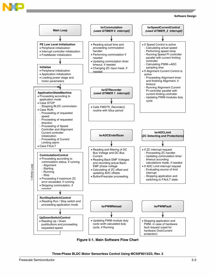
Software Design
Three-Phase BLDC Motor Sensorless Control Using MC56F8013/23, Rev. 2
Freescale Semiconductor 5-3
Figure 5-1. Main Software Flow Chart
IsrCommutation(used QTIMER 0 interrupt)
• Reading actual time and proceeding commutation handler
• Performing commutation if needed
• Updating commutation timer timeout, if needed
• Changing ZC input mask, if needed
IsrADCEndofScan
• Reading and filtering of DC Bus Voltage and DC Bus Current
• Reading Back EMF Voltages and recording actual Back-EMF phase voltage
• Calculating of ZC offset and updating ADC offsets
• ButtonPrescaler proceeding
IsrADCLimit (ZC Detecting and Protections)
• If ZC interrupt request - Proceeding ZC handler - Updating commutation timer
timeout according calculations made, if needed
• If ADC Limit interrupt request - Evaluating source of limit
interrupt - Stopping application and
switching to FAULT state
IsrSpeedCurrentControl(used QTIMER_2 interrupt)
• If Speed Control is active - Calculating actual speed - Performing speed ramp - Running Speed PI controller
parallel with current limiting controller
- Calculating PWM->ADC sampling time
• If Alignment Current Control is active - Proceeding Alignment timer
and finishing Alignment, if timeout
- Running Alignment Current PI controller parallel with current limiting controller
- Updating PWM modules duty cycle
IsrPWMFault
• Stopping application and PWM, in case of hardware fault request (used for hardware OverCurrent protection)
Main Loop
Initialize • Peripheral initialization • Application initialization • Loading power stage and
motor parameters
ApplicationStateMachine • Proceeding according to
application mode • Case STOP
- Stopping BLDC commutator • Case RUN
- Proceeding of requested speed
- Proceeding of requested direction
- Proceeding of Speed Controller and Alignment Current controller initialization
- Proceeding of Current Limiting alarm
• Case FAULT
CommutationControl • Proceeding according to
commutation status, if running - Alignment - Starting - Running - Stop
• Proceeding if maximum ZC error exceeded, if running
• Stopping commutation, if needed
RunStopSwitchControl • Reading Run / Stop switch and
proceeding application mode
UpDownSwitchControl • Reading Up / Down
pushbuttons and proceeding requested speed
IsrPWMReload
• Updating PWM module duty cycle woth calculated duty cycle, if Running
PE Low Level Initialization • Peripheral initialization • Interrupt controller initialization • FreeMaster initialization
I nfin
ite L
oop
IsrQTRecorder(used QTIMER 1 interrupt)
• Calls FMSTR_Recorder() routine with 50us period
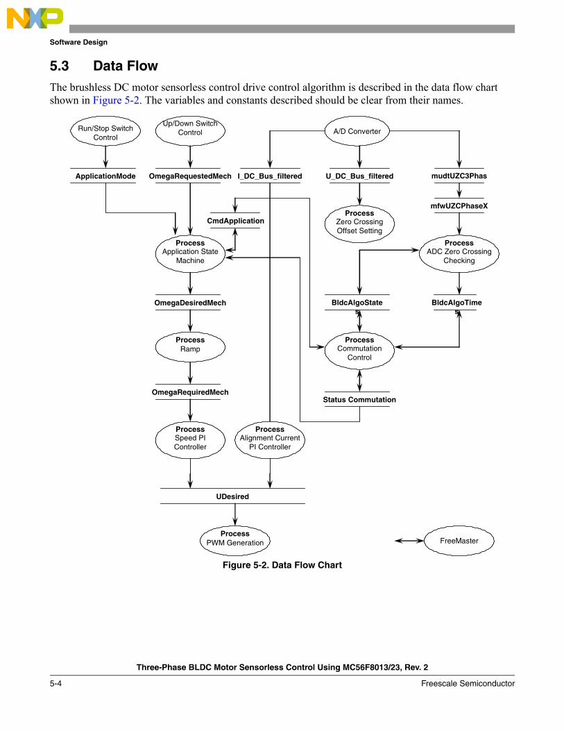
Software Design
Three-Phase BLDC Motor Sensorless Control Using MC56F8013/23, Rev. 2
5-4 Freescale Semiconductor
5.3 Data FlowThe brushless DC motor sensorless control drive control algorithm is described in the data flow chart shown in Figure 5-2. The variables and constants described should be clear from their names.
Figure 5-2. Data Flow Chart
A/D Converter
U_DC_Bus_filtered
ProcessZero Crossing Offset Setting
mudtUZC3Phas
ProcessADC Zero Crossing
Checking
mfwUZCPhaseX
I_DC_Bus_filtered
ProcessAlignment Current
PI Controller
OmegaRequestedMech
Up/Down Switch Control
Process Application State
Machine
OmegaDesiredMech
OmegaRequiredMech
Process Ramp
Process Speed PI Controller
CmdApplication
UDesired
ProcessPWM Generation
Run/Stop Switch Control
ApplicationMode
ProcessCommutation
Control
BldcAlgoTimes
Status Commutation
FreeMaster
BldcAlgoStates

Software Design
Three-Phase BLDC Motor Sensorless Control Using MC56F8013/23, Rev. 2
Freescale Semiconductor 5-5
5.3.1 Process Application State Machine
This process controls the application states by status and command words. • Run and stop states of application are managed. Based on the state of the application,
Cmd_Application command (Cmd) request (Rq) flags are processed.• Requested speed (via up/down switches or FreeMaster) is converted to desired speed by minimum
control and sign processing.• Alignment commutation status is initiated and finished, if needed.• PWM duty cycle values and PWM outputs are modified to no-pwm state if application is in stop
state or requested speed is below a minimum.
5.3.2 Process Commutation Control
This process controls sensorless BLDC motor commutations as explained in Section 5.1, “Introduction”. The process is mainly communicated over BldcAlgoStates and BldcAlgoTimes structures.
• All commutation states (stop, alignment, starting, and run) are managed separately.• Commutation and other commutation timing activities are performed. (IsrCommutation)
5.3.3 Process A/D Converter Zero Crossing Checking
This process is based on the A/D converter zero crossing feature. When the non fed phase branch voltage changes the sign comparing previous conversion results, the zero crossing interrupt is initiated.
• Instant of zero crossing interrupt is saved through BldcAlgoTimes structure.
5.3.4 Process Zero Crossing Offset Setting
To ensure proper behavior of the A/D converter zero crossing checking, the A/D converter zero crossing offset registers must be set the way that the zero back-EMF voltage is converted to zero A/D converter value. Because phase voltages changes between 0 V and DC-bus voltage value, zero crossing offset registers must be set to half of DC-bus voltage value.
This process is performed periodically inside IsrSpeedCurrentControl.• The A/D converter offset registers for all free phase voltages are set to U_Dc_Bus_Half.
5.3.5 Process Speed PI Controller
The general principle of the speed PI control loop is illustrated in Figure 5-3.
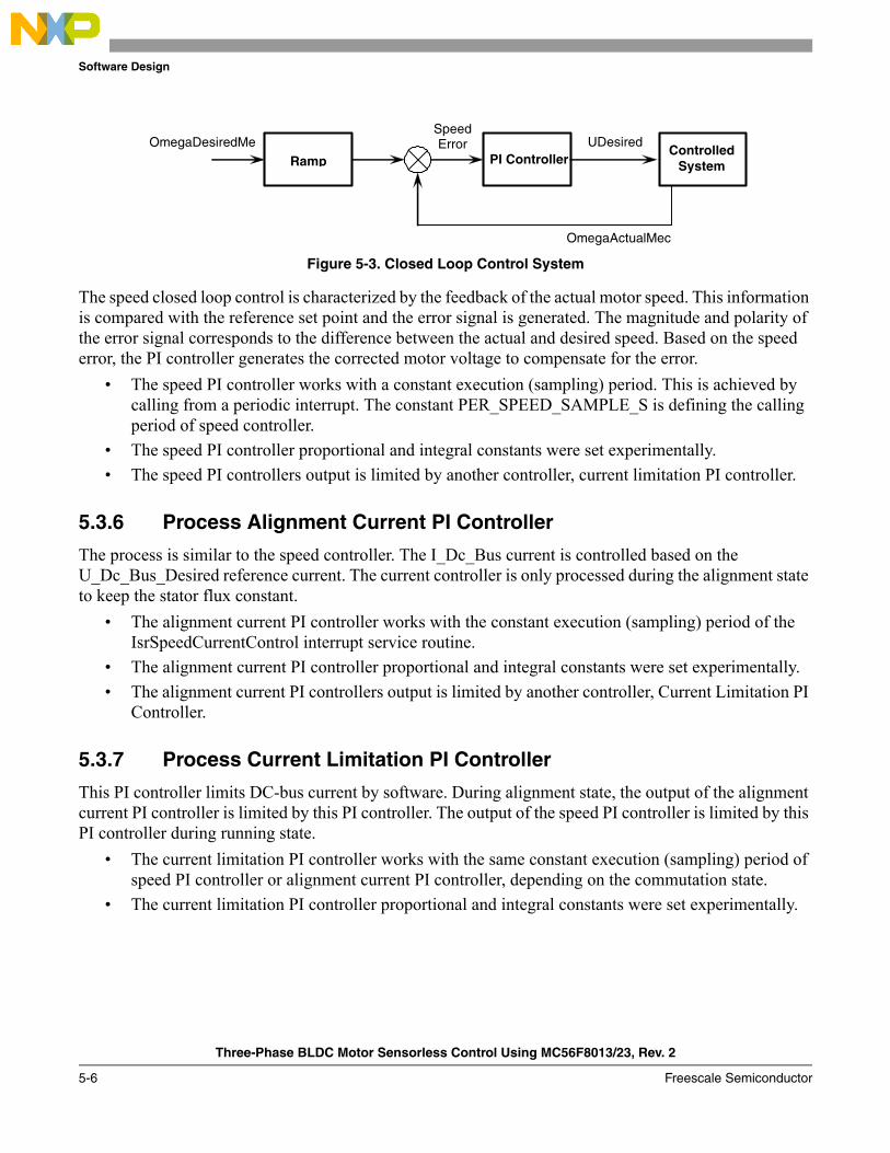
Software Design
Three-Phase BLDC Motor Sensorless Control Using MC56F8013/23, Rev. 2
5-6 Freescale Semiconductor
Figure 5-3. Closed Loop Control System
The speed closed loop control is characterized by the feedback of the actual motor speed. This information is compared with the reference set point and the error signal is generated. The magnitude and polarity of the error signal corresponds to the difference between the actual and desired speed. Based on the speed error, the PI controller generates the corrected motor voltage to compensate for the error.
• The speed PI controller works with a constant execution (sampling) period. This is achieved by calling from a periodic interrupt. The constant PER_SPEED_SAMPLE_S is defining the calling period of speed controller.
• The speed PI controller proportional and integral constants were set experimentally.• The speed PI controllers output is limited by another controller, current limitation PI controller.
5.3.6 Process Alignment Current PI Controller
The process is similar to the speed controller. The I_Dc_Bus current is controlled based on the U_Dc_Bus_Desired reference current. The current controller is only processed during the alignment state to keep the stator flux constant.
• The alignment current PI controller works with the constant execution (sampling) period of the IsrSpeedCurrentControl interrupt service routine.
• The alignment current PI controller proportional and integral constants were set experimentally.• The alignment current PI controllers output is limited by another controller, Current Limitation PI
Controller.
5.3.7 Process Current Limitation PI Controller
This PI controller limits DC-bus current by software. During alignment state, the output of the alignment current PI controller is limited by this PI controller. The output of the speed PI controller is limited by this PI controller during running state.
• The current limitation PI controller works with the same constant execution (sampling) period of speed PI controller or alignment current PI controller, depending on the commutation state.
• The current limitation PI controller proportional and integral constants were set experimentally.
Ramp PI Controller Controlled
System
Speed ErrorOmegaDesiredMe
OmegaActualMec
UDesired
Software Design
Three-Phase BLDC Motor Sensorless Control Using MC56F8013/23, Rev. 2
Freescale Semiconductor 5-7
5.3.8 Process PWM Generation
The Process PWM Generation creates the following:• BLDC motor commutation pattern as described in Section 2.1, “Brushless DC Motor (BLDC
Motor)”• Required duty cycle
5.3.9 Process Fault Control
The process fault control is used for drive protection. The DriveFaultStatus is passed to the PWM generation process and to the application state machine process to disable the PWMs and to control the application accordingly.

Software Design
Three-Phase BLDC Motor Sensorless Control Using MC56F8013/23, Rev. 2
5-8 Freescale Semiconductor
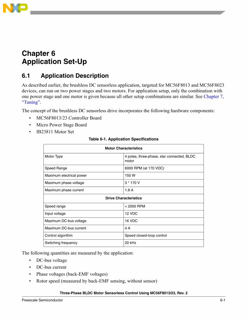
Three-Phase BLDC Motor Sensorless Control Using MC56F8013/23, Rev. 2
Freescale Semiconductor 6-1
Chapter 6 Application Set-Up
6.1 Application DescriptionAs described earlier, the brushless DC sensorless application, targeted for MC56F8013 and MC56F8023 devices, can run on two power stages and two motors. For application setup, only the combination with one power stage and one motor is given because all other setup combinations are similar. See Chapter 7, “Tuning”.
The concept of the brushless DC sensorless drive incorporates the following hardware components:• MC56F8013/23 Controller Board• Micro Power Stage Board• IB23811 Motor Set
The following quantities are measured by the application:• DC-bus voltage• DC-bus current• Phase voltages (back-EMF voltages)• Rotor speed (measured by back-EMF sensing, without sensor)
Table 6-1. Application Specifications
Motor Characteristics
Motor Type 4 poles, three-phase, star connected, BLDC motor
Speed Range 6000 RPM (at 170 VDC)
Maximum electrical power 150 W
Maximum phase voltage 3 * 170 V
Maximum phase current 1.8 A
Drive Characteristics
Speed range < 2000 RPM
Input voltage 12 VDC
Maximum DC-bus voltage 16 VDC
Maximum DC-bus current 4 A
Control algorithm Speed closed-loop control
Switching frequency 20 kHz
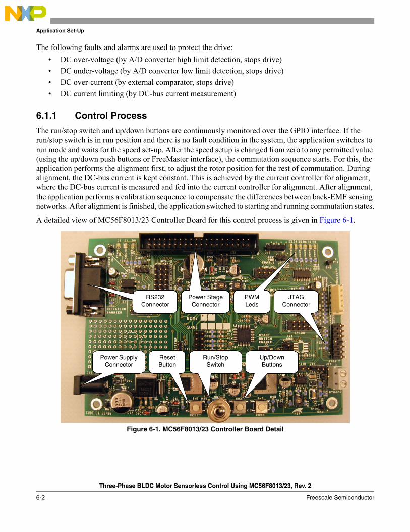
Application Set-Up
Three-Phase BLDC Motor Sensorless Control Using MC56F8013/23, Rev. 2
6-2 Freescale Semiconductor
The following faults and alarms are used to protect the drive:• DC over-voltage (by A/D converter high limit detection, stops drive)• DC under-voltage (by A/D converter low limit detection, stops drive)• DC over-current (by external comparator, stops drive)• DC current limiting (by DC-bus current measurement)
6.1.1 Control Process
The run/stop switch and up/down buttons are continuously monitored over the GPIO interface. If the run/stop switch is in run position and there is no fault condition in the system, the application switches to run mode and waits for the speed set-up. After the speed setup is changed from zero to any permitted value (using the up/down push buttons or FreeMaster interface), the commutation sequence starts. For this, the application performs the alignment first, to adjust the rotor position for the rest of commutation. During alignment, the DC-bus current is kept constant. This is achieved by the current controller for alignment, where the DC-bus current is measured and fed into the current controller for alignment. After alignment, the application performs a calibration sequence to compensate the differences between back-EMF sensing networks. After alignment is finished, the application switched to starting and running commutation states.
A detailed view of MC56F8013/23 Controller Board for this control process is given in Figure 6-1.
Figure 6-1. MC56F8013/23 Controller Board Detail
ResetButton
Run/StopSwitch
Up/DownButtons
RS232 Connector
Power Stage Connector
JTAG Connector
PWM Leds
Power Supply Connector
Application Set-Up
Three-Phase BLDC Motor Sensorless Control Using MC56F8013/23, Rev. 2
Freescale Semiconductor 6-3
6.1.2 Drive Protection
The DC-bus voltage is measured during the control process. It protects the drive from DC over-voltage and DC under-voltage. This protection is performed by the help of the A/D converter when it generates an interrupt if limits are exceeded. In this case, PWM outputs are disabled and drive is stopped. Similarly, the DC-bus current is also measured for current limitation. If the DC-bus current is higher than the desired current, the PWM duty cycles are limited. It is intended to limit the DC-bus current. This is a software limitation. Beyond this, DC-bus current is compared on an external comparator and output of the comparator is fed to the fault input of the PWM module. If the DC-bus current exceeds set value by the external trimpot, a fault signal is generated to the DSC and drive is stopped. All described fault and alarm messages are displayed on FreeMaster screen.
After the drive enters a fault state, it waits until the fault is reset. Fault can be reset in two ways:• By clicking the reset button on FreeMASTER screen• Switching the run/stop switch on MC56F8013/23 controller board to the off position
6.1.3 FreeMASTER Interface
FreeMASTER software was designed to provide a debugging, diagnostic and demonstration tool for development of algorithms and applications. Moreover, it is useful for tuning the application for different power stages and motors, because almost all the application parameters can be changed by FreeMaster interface. FreeMaster consists of a component running on a PC and a part running on the target DSC, connected via an RS-232 serial port. A small program resides in the DSC that communicates with FreeMASTER software to parse commands, return status information to the PC, and processes control information from the PC. FreeMASTER software executes on the PC using Microsoft Internet Explorer as the user interface.
6.1.3.1 FreeMASTER Serial Communication Driver
The latest version of sensorless BLDC application includes FreeMASTER Serial Communication Driver. The FreeMASTER Serial Communication Driver fully replaces former PC Master driver and PC Master Bean. The new FreeMASTER driver remains fully-compatible with the communication interface provided by the old PC Master drivers. It brings, however, many useful enhancements and optimizations.
The main advantage of the new driver is a unification across all supported Freescale processor products. Several new features were also added. One of the key features implemented in the new driver is a target-side addressing (TSA), which enables an embedded application to describe memory objects it grants the host access to. By enabling the TSA-Safety option, the application memory can be protected from illegal or invalid memory accesses.
The FreeMASTER Serial Communication Driver is not available as ProcessorExpert bean at this stage. To include the new drive to the application, include the driver files to the CodeWarrior project on his own. For the presented sensorless BLDC application, the drive has already been included.

Application Set-Up
Three-Phase BLDC Motor Sensorless Control Using MC56F8013/23, Rev. 2
6-4 Freescale Semiconductor
The FreeMASTER driver files are located in following folders:• {Project}support\freemaster\56F8xxx, contains platform-dependent driver C-source and header
files including a master header file freemaster.h.• {Project}support\freemaster\common, contains common driver source files, shared by the driver
for all supported platforms.
All C files included in the FreeMASTER folders are added to the project for compilation and linking (see support group in the project). The master header file freemaster.h declares the common data types, macros and prototypes of the FreeMASTER driver API functions. It should be included in your application (using #include directive) where you need to call any of FreeMASTER driver API functions.
The FreeMASTER driver does not perform any initialization or configuration of the SCI module it uses to communicate. You must configure the communication module before the FreeMASTER driver is initialized by the FMSTR_Init() call. The SCI module is initialized using ProcessorExpert SCI Peripheral Bean. The default baud rate of the SCI communication is set to 9600 Bd. Higher communication speed is not supported by the MC56F8013/23 Controller Board due to limited speed of opto-couplers.
The FreeMASTER uses a poll-driven communication in the sensorless BLDC application. It does not require setting of interrupts for SCI. Communication and protocol decoding is managed in application background loop. The polling-mode requires a periodic call of the FMSTR_Poll function in the application main.
The driver is configured using a single header file, named freemaster_cfg.h located in project root. You must modify this file to configure FreeMASTER driver. The FreeMASTER driver C-source files include the freemaster_cfg.h file and use macros defined here for conditional and parametrized compilation.
A detailed description of FreeMASTER Serial Communication Driver is provided in the FreeMASTER Serial Communication Driver User's Manual.
6.1.3.2 FreeMASTER Serial Communication Driver
Part of the FreeMASTER software is also a recorder, which is able to sample the application variables at a specified sample rate. The samples are stored to a buffer and read by the PC via an RS232 serial port. The sampled data can be displayed in a graph or the data can be stored. The recorder behaves like a simple on-chip oscilloscope with trigger/pretrigger capabilities. The size of the recorder buffer and the FreeMASTER recorder time base can be defined in freemaster_cfg.h configuration.
The recorder routine must be called periodically in the loop in which you want to take the samples. The following line must be added to the loop code:
FMSTR_Recorder(); /* FreeMASTER recorder routine call */
In this application, FreeMaster recorder is called from the QuadTimer channel 1 interrupt, which creates a 50 μs time-base for the recorder function. The FreeMASTER recorder is the only routine called in this interrupt.
A detailed description of Free Master software is provided in the FreeMASTER Software User Manual.
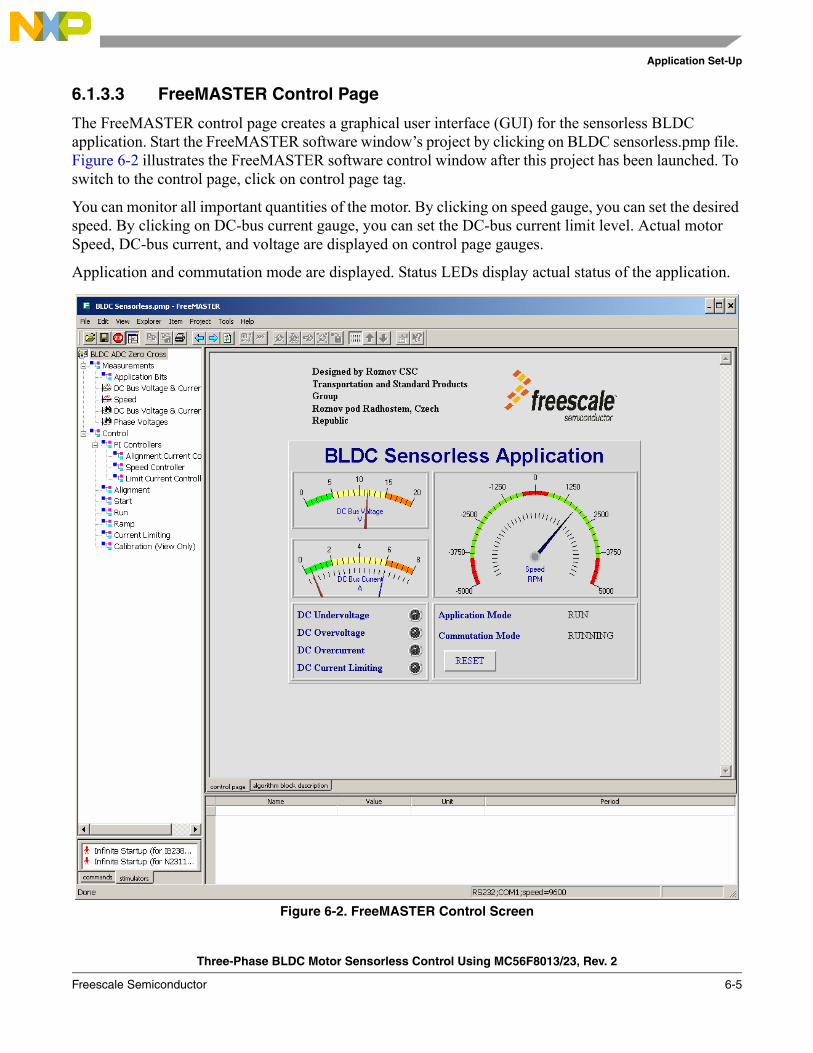
Application Set-Up
Three-Phase BLDC Motor Sensorless Control Using MC56F8013/23, Rev. 2
Freescale Semiconductor 6-5
6.1.3.3 FreeMASTER Control Page
The FreeMASTER control page creates a graphical user interface (GUI) for the sensorless BLDC application. Start the FreeMASTER software window’s project by clicking on BLDC sensorless.pmp file. Figure 6-2 illustrates the FreeMASTER software control window after this project has been launched. To switch to the control page, click on control page tag.
You can monitor all important quantities of the motor. By clicking on speed gauge, you can set the desired speed. By clicking on DC-bus current gauge, you can set the DC-bus current limit level. Actual motor Speed, DC-bus current, and voltage are displayed on control page gauges.
Application and commutation mode are displayed. Status LEDs display actual status of the application.
Figure 6-2. FreeMASTER Control Screen
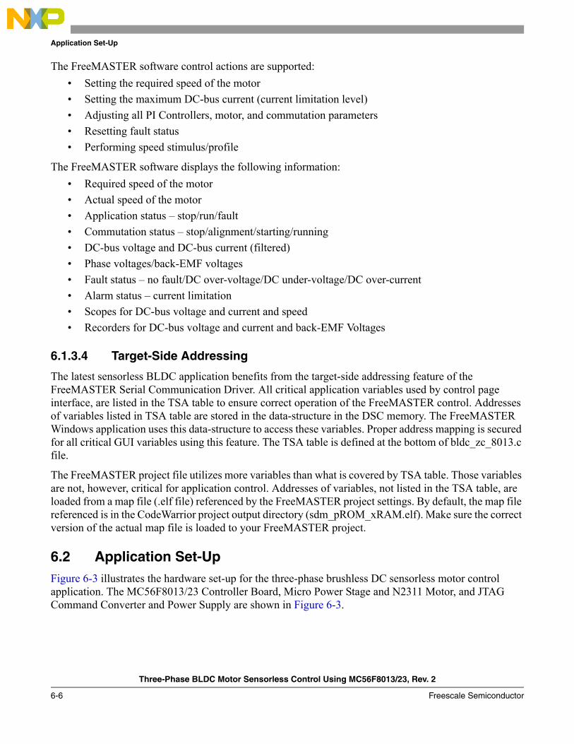
Application Set-Up
Three-Phase BLDC Motor Sensorless Control Using MC56F8013/23, Rev. 2
6-6 Freescale Semiconductor
The FreeMASTER software control actions are supported:• Setting the required speed of the motor• Setting the maximum DC-bus current (current limitation level)• Adjusting all PI Controllers, motor, and commutation parameters• Resetting fault status• Performing speed stimulus/profile
The FreeMASTER software displays the following information:• Required speed of the motor• Actual speed of the motor• Application status – stop/run/fault• Commutation status – stop/alignment/starting/running• DC-bus voltage and DC-bus current (filtered)• Phase voltages/back-EMF voltages• Fault status – no fault/DC over-voltage/DC under-voltage/DC over-current• Alarm status – current limitation• Scopes for DC-bus voltage and current and speed• Recorders for DC-bus voltage and current and back-EMF Voltages
6.1.3.4 Target-Side Addressing
The latest sensorless BLDC application benefits from the target-side addressing feature of the FreeMASTER Serial Communication Driver. All critical application variables used by control page interface, are listed in the TSA table to ensure correct operation of the FreeMASTER control. Addresses of variables listed in TSA table are stored in the data-structure in the DSC memory. The FreeMASTER Windows application uses this data-structure to access these variables. Proper address mapping is secured for all critical GUI variables using this feature. The TSA table is defined at the bottom of bldc_zc_8013.c file.
The FreeMASTER project file utilizes more variables than what is covered by TSA table. Those variables are not, however, critical for application control. Addresses of variables, not listed in the TSA table, are loaded from a map file (.elf file) referenced by the FreeMASTER project settings. By default, the map file referenced is in the CodeWarrior project output directory (sdm_pROM_xRAM.elf). Make sure the correct version of the actual map file is loaded to your FreeMASTER project.
6.2 Application Set-UpFigure 6-3 illustrates the hardware set-up for the three-phase brushless DC sensorless motor control application. The MC56F8013/23 Controller Board, Micro Power Stage and N2311 Motor, and JTAG Command Converter and Power Supply are shown in Figure 6-3.
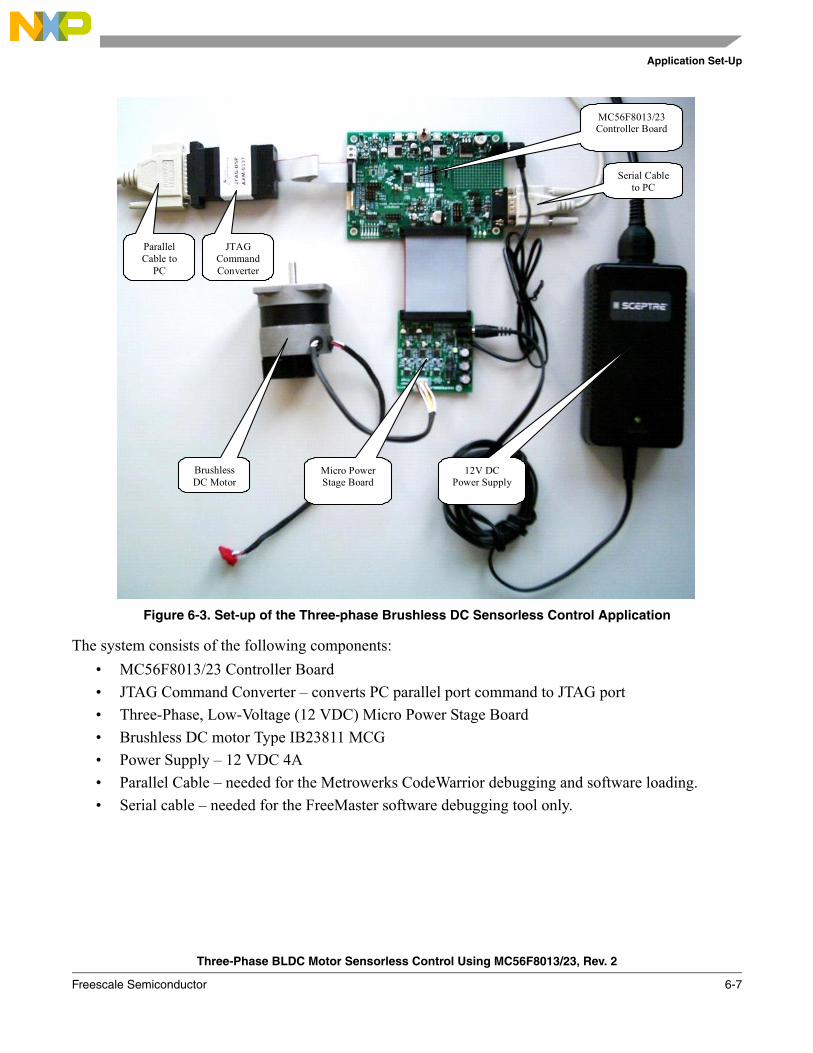
Application Set-Up
Three-Phase BLDC Motor Sensorless Control Using MC56F8013/23, Rev. 2
Freescale Semiconductor 6-7
Figure 6-3. Set-up of the Three-phase Brushless DC Sensorless Control Application
The system consists of the following components:• MC56F8013/23 Controller Board• JTAG Command Converter – converts PC parallel port command to JTAG port• Three-Phase, Low-Voltage (12 VDC) Micro Power Stage Board• Brushless DC motor Type IB23811 MCG• Power Supply – 12 VDC 4A• Parallel Cable – needed for the Metrowerks CodeWarrior debugging and software loading.• Serial cable – needed for the FreeMaster software debugging tool only.
JTAG Command Converter
Parallel Cable to
PC
MC56F8013/23 Controller Board
Serial Cable to PC
Brushless DC Motor
Micro Power Stage Board
12V DC Power Supply
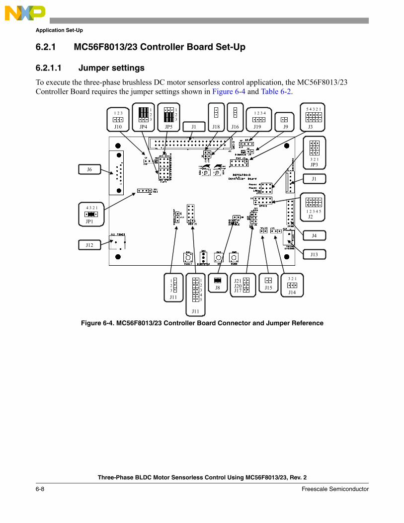
Application Set-Up
Three-Phase BLDC Motor Sensorless Control Using MC56F8013/23, Rev. 2
6-8 Freescale Semiconductor
6.2.1 MC56F8013/23 Controller Board Set-Up
6.2.1.1 Jumper settings
To execute the three-phase brushless DC motor sensorless control application, the MC56F8013/23 Controller Board requires the jumper settings shown in Figure 6-4 and Table 6-2.
Figure 6-4. MC56F8013/23 Controller Board Connector and Jumper Reference
JP5JP4 J1 J18J10
1 2 3
J6
JP1
4 3 2 1
J12
J16 J19
1 2 3 4
J9 J3
5 4 3 2 1
JP3 3 2 1
J1
J4
J2 1 2 3 4 5
J13
J14
3 2 1
J15J21J20J17J8
J11
123
J11
12345
1 2 3
123
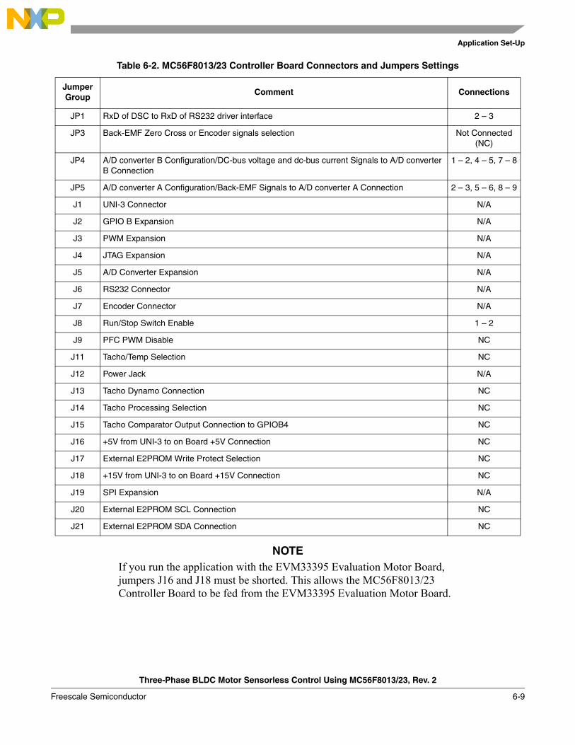
Application Set-Up
Three-Phase BLDC Motor Sensorless Control Using MC56F8013/23, Rev. 2
Freescale Semiconductor 6-9
NOTEIf you run the application with the EVM33395 Evaluation Motor Board, jumpers J16 and J18 must be shorted. This allows the MC56F8013/23 Controller Board to be fed from the EVM33395 Evaluation Motor Board.
Table 6-2. MC56F8013/23 Controller Board Connectors and Jumpers Settings
Jumper Group
Comment Connections
JP1 RxD of DSC to RxD of RS232 driver interface 2 – 3
JP3 Back-EMF Zero Cross or Encoder signals selection Not Connected (NC)
JP4 A/D converter B Configuration/DC-bus voltage and dc-bus current Signals to A/D converter B Connection
1 – 2, 4 – 5, 7 – 8
JP5 A/D converter A Configuration/Back-EMF Signals to A/D converter A Connection 2 – 3, 5 – 6, 8 – 9
J1 UNI-3 Connector N/A
J2 GPIO B Expansion N/A
J3 PWM Expansion N/A
J4 JTAG Expansion N/A
J5 A/D Converter Expansion N/A
J6 RS232 Connector N/A
J7 Encoder Connector N/A
J8 Run/Stop Switch Enable 1 – 2
J9 PFC PWM Disable NC
J11 Tacho/Temp Selection NC
J12 Power Jack N/A
J13 Tacho Dynamo Connection NC
J14 Tacho Processing Selection NC
J15 Tacho Comparator Output Connection to GPIOB4 NC
J16 +5V from UNI-3 to on Board +5V Connection NC
J17 External E2PROM Write Protect Selection NC
J18 +15V from UNI-3 to on Board +15V Connection NC
J19 SPI Expansion N/A
J20 External E2PROM SCL Connection NC
J21 External E2PROM SDA Connection NC
Application Set-Up
Three-Phase BLDC Motor Sensorless Control Using MC56F8013/23, Rev. 2
6-10 Freescale Semiconductor
6.2.1.2 Trimpot settings
MC56F8013/23 Controller Board contains three trimpots.• R29, DC over-voltage Hardware Fault Setpoint
In this application, DC over-voltage Hardware Fault is not used. Therefore, in Micro Power Stage Board, this trimpot (TP3) should be adjusted to 3.3 V to avoid DC over-voltage fault.
• R32, DC over-current Hardware Fault SetpointIn Micro Power Stage Board, the DC-bus current is samples as 200 mV/A. This trimpot (TP5) should be adjusted to 2.85 V to have a DC over-current fault at peak 6 A (1.65V offset).
• R54, Tacho-Dynamo Sense Threshold SetpointIn this application, Tacho-Dynamo section of the MC56F8013/23 Controller Board is not used. Therefore, setting this trimpot can be ignored.
6.3 Projects FilesThe application is created using CodeWarrior 8.1 and Processor Expert 3.98.01
The BLDC sensorless application is composed of the following files:• {Project}\bldc_zc_80xx.mcp, application project file• {Project}\bldczcdefines.h, header file containing definition of application parameters• {Project}\code\bldcadczcconfig.h , header file specifiing hardware set-up• {Project}\code\bldc_zc_80xx.c, main program• {Project}\code\bldcdrv.c , brusheless DC motor driver implementation• {Project}\code\bldcdrv.h , definition of constants for brusheless DC motor driver• {Project}\code\BldcZC.c , brusheless DC motor zero crossing functions• {Project}\code\BldcZC.h , header file for brusheless DC motor zero crossing functions• {Project}\code\smm_pROM_xRAM.cmd, linker command file• {Project}\output\sdm_pROM_xRAM.elf, executable application file• {Project}\output\sdm_pROM_xRAM.elf.xMAP, MAP file• {Project}\FreeMasterPage\BLDC Sensorless.pmp, FreeMaster software file

Application Set-Up
Three-Phase BLDC Motor Sensorless Control Using MC56F8013/23, Rev. 2
Freescale Semiconductor 6-11
6.4 Application Build and Execute When building the brushless DC motor sensorless control application, you can create an application only that runs from internal flash because MC56F8013/8023 does not support external RAM.
From the Metrowerks Code Warrior IDE, the project may be built by executing the project/make command, as shown in Figure 6-5. This builds and links the brushless DC motor sensorless control application and all needed Metrowerks and Processor Expert libraries.
To execute the application, select project/debug in the CodeWarrior IDE, followed by the run command. For more help with these commands, refer to the CodeWarrior tutorial documentation in the following file located in the CodeWarrior installation folder:
<...>\CodeWarrior Documentation\PDF\Targeting_DSP56800.pdf
If the flash target is selected, CodeWarrior automatically programs the internal flash of the DSC with the executable generated during build. After flash has been programmed with the binary image, the EVM target system may be run in a stand-alone mode from flash.
After the application is running, move the run/stop switch to the run position and set the required speed using the up/down push buttons. Pressing the up/down buttons should incrementally increase the motor speed until it reaches maximum speed. If successful, the motor spins.

Application Set-Up
Three-Phase BLDC Motor Sensorless Control Using MC56F8013/23, Rev. 2
6-12 Freescale Semiconductor
Figure 6-5. Executing Make Command
Three-Phase BLDC Motor Sensorless Control Using MC56F8013/23, Rev. 2
Freescale Semiconductor 7-1
Chapter 7 Tuning
7.1 IntroductionBLDC sensorless application is designed to cover a wide concept of brushless DC motor sensorless control. Because of its parametric structure, you can change the behavior of the application so it can be adjusted/tuned for different processors, power stages, and motors. Moreover, FreeMASTER interface makes this tuning process more easier.
7.2 ClassificationThe software is tuned for two power stages (EVM33395, Micro Power) and two motors (MCG IB2381, Pittman N2311) as described in this DRM. It can of course be used for other motors, but the software parameters need to be set accordingly.
The software parameters are divided into three main groups:• Group 1/Application Related Parameters
— These parameters are depending on the DSC used, and the application performance. It mainly includes parameters like calling frequency of speed controller, DC-bus voltage reading filtering constants, etc. These parameters are mainly defined in bldczcdefines.h.
— There are also some mask definitions related to the hardware used. These masks are mainly defined inside bldcdrv.h and used in bldcdrv.c.
• Group 2/Power Stage Related Parameters— Parameters included in this group have no relation with the motor. After these parameters are
set properly, several motors with the same power stage can only be driven by tuning parameters in group 2.
— These parameters are mainly defined in bldczcdefines.h.— In this application, these parameters are called EVM33395_xxx and MP_xxx, where xxx is the
parameter name.— To use the desired parameter set in the main software, there are two functions defined:
– EVM33395 Board Settings– MP Board Settings
• Group 3/Motor Related Parameters— These parameters are not related with the power stage. After these parameters are set properly,
only other power stages can be used to drive the same motor by tuning parameters in group 1.— These parameters are mainly defined in bldczcdefines.h.
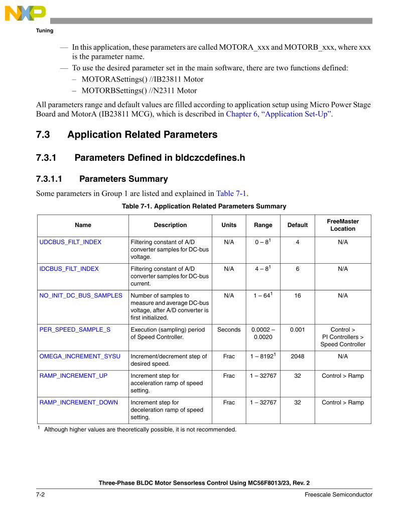
Tuning
Three-Phase BLDC Motor Sensorless Control Using MC56F8013/23, Rev. 2
7-2 Freescale Semiconductor
— In this application, these parameters are called MOTORA_xxx and MOTORB_xxx, where xxx is the parameter name.
— To use the desired parameter set in the main software, there are two functions defined:– MOTORASettings() //IB23811 Motor– MOTORBSettings() //N2311 Motor
All parameters range and default values are filled according to application setup using Micro Power Stage Board and MotorA (IB23811 MCG), which is described in Chapter 6, “Application Set-Up”.
7.3 Application Related Parameters
7.3.1 Parameters Defined in bldczcdefines.h
7.3.1.1 Parameters Summary
Some parameters in Group 1 are listed and explained in Table 7-1.Table 7-1. Application Related Parameters Summary
Name Description Units Range DefaultFreeMaster
Location
UDCBUS_FILT_INDEX Filtering constant of A/D converter samples for DC-bus voltage.
N/A 0 – 81
1 Although higher values are theoretically possible, it is not recommended.
4 N/A
IDCBUS_FILT_INDEX Filtering constant of A/D converter samples for DC-bus current.
N/A 4 – 81 6 N/A
NO_INIT_DC_BUS_SAMPLES Number of samples to measure and average DC-bus voltage, after A/D converter is first initialized.
N/A 1 – 641 16 N/A
PER_SPEED_SAMPLE_S Execution (sampling) period of Speed Controller.
Seconds 0.0002 – 0.0020
0.001 Control > PI Controllers >
Speed Controller
OMEGA_INCREMENT_SYSU Increment/decrement step of desired speed.
Frac 1 – 81921 2048 N/A
RAMP_INCREMENT_UP Increment step for acceleration ramp of speed setting.
Frac 1 – 32767 32 Control > Ramp
RAMP_INCREMENT_DOWN Increment step for deceleration ramp of speed setting.
Frac 1 – 32767 32 Control > Ramp

Tuning
Three-Phase BLDC Motor Sensorless Control Using MC56F8013/23, Rev. 2
Freescale Semiconductor 7-3
7.3.1.2 UDCBUS_FILT_INDEX
DC-bus voltage is sampled through the A/D converter. Because samples received from the A/D converter may include noise from the switching mode application, they are applied to an exponential filter as (inside ADCEndOfScan interrupt):
mfwUDCBusSum += mfwUDCBusSample;mfwUDCBus = mfwUDCBusSum >> UDCBUS_FILT_INDEX;mfwUDCBusSum -= mfwUDCBus;
In this filtering method, the output of the filter approximates to the input filter exponentially, which eliminates noise effectively. As can be seen, a higher UDCBUS_FILT_INDEX value performs better filtering, but this also causes delay and phase shift.
Figure 7-1. Step Response of Exponential Filter
7.3.1.3 IDCBUS_FILT_INDEX
DC-bus current is sampled through the A/D converter. Because samples received from the A/D converter may include noise from the switching mode application, these samples are applied to an exponential filter as following (inside ADCEndOfScan interrupt):
mfwIDCBusSum += mfwIDCBusSample;mfwIDCBus = mfwIDCBusSum >> IDCBUS_FILT_INDEX;mfwIDCBusSum -= mfwIDCBus;
In this filtering method, the output of the filter approximates to the input filter exponentially, which eliminates noise effectively. As can be seen, a higher IDCBUS_FILT_INDEX value performs better filtering, but this also causes delay and phase shift.
Exponantiel filter
Smaller FILT_INDEX
Bigger FILT_INDEX
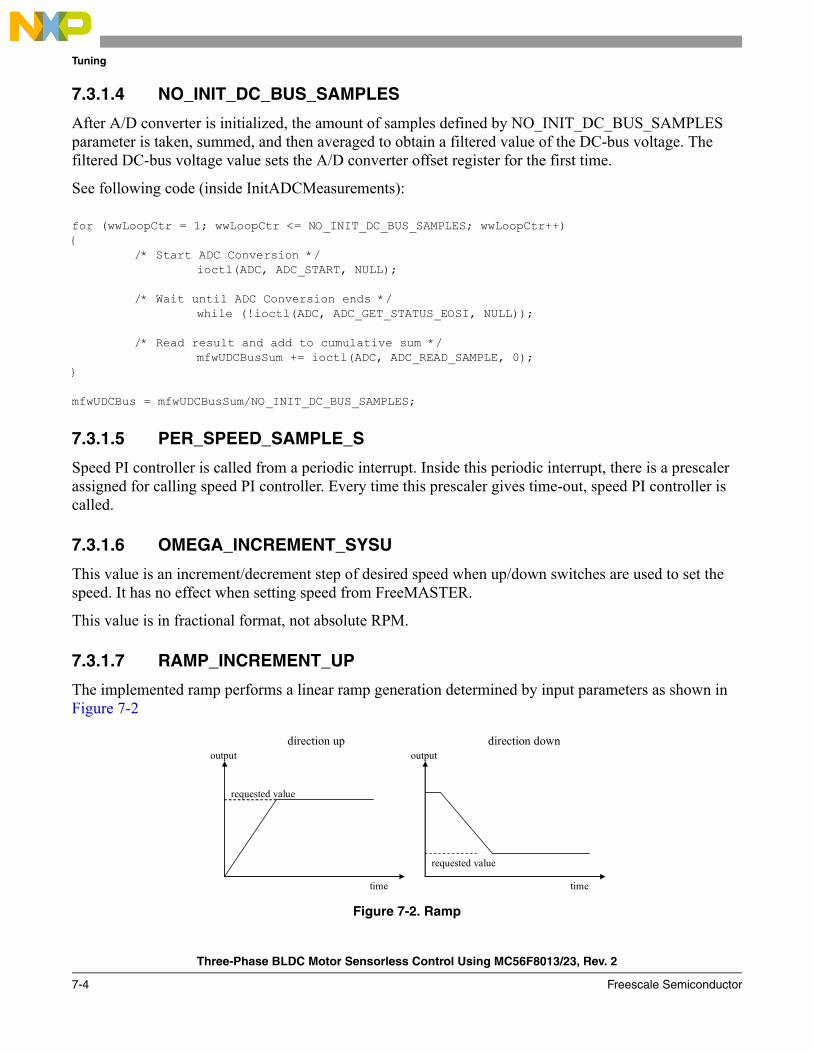
Tuning
Three-Phase BLDC Motor Sensorless Control Using MC56F8013/23, Rev. 2
7-4 Freescale Semiconductor
7.3.1.4 NO_INIT_DC_BUS_SAMPLES
After A/D converter is initialized, the amount of samples defined by NO_INIT_DC_BUS_SAMPLES parameter is taken, summed, and then averaged to obtain a filtered value of the DC-bus voltage. The filtered DC-bus voltage value sets the A/D converter offset register for the first time.
See following code (inside InitADCMeasurements):
for (wwLoopCtr = 1; wwLoopCtr <= NO_INIT_DC_BUS_SAMPLES; wwLoopCtr++){
/* Start ADC Conversion */ioctl(ADC, ADC_START, NULL);
/* Wait until ADC Conversion ends */
while (!ioctl(ADC, ADC_GET_STATUS_EOSI, NULL));
/* Read result and add to cumulative sum */mfwUDCBusSum += ioctl(ADC, ADC_READ_SAMPLE, 0);
}
mfwUDCBus = mfwUDCBusSum/NO_INIT_DC_BUS_SAMPLES;
7.3.1.5 PER_SPEED_SAMPLE_S
Speed PI controller is called from a periodic interrupt. Inside this periodic interrupt, there is a prescaler assigned for calling speed PI controller. Every time this prescaler gives time-out, speed PI controller is called.
7.3.1.6 OMEGA_INCREMENT_SYSU
This value is an increment/decrement step of desired speed when up/down switches are used to set the speed. It has no effect when setting speed from FreeMASTER.
This value is in fractional format, not absolute RPM.
7.3.1.7 RAMP_INCREMENT_UP
The implemented ramp performs a linear ramp generation determined by input parameters as shown in Figure 7-2
Figure 7-2. Ramp
output
time
direction up
requested value
output
time
direction down
requested value

Tuning
Three-Phase BLDC Motor Sensorless Control Using MC56F8013/23, Rev. 2
Freescale Semiconductor 7-5
If the requestedValue is greater than actualValue, the rampGetValue function returns actualValue + incrementUp until the maximum is reached, (maximum is requestedValue), at which point it returns the requestedValue.
If the requestedValue is less than actualValue, the rampGetValue function returns actualValue/incrementDown until the minimum is reached, (minimum is requestedValue), at which point it returns the requestedValue.
This value is in fractional format, not absolute RPM.
7.3.1.8 RAMP_INCREMENT_DOWN
Decrement step for decceleration ramp of speed setting.
7.3.2 Parameters Defined in bldcdrv.h (Masks)
These mask definitions are related with the DSC and hardware used. They mainly include A/D converter masks for zero crossing checking and PWM masks for hard and soft switching pattern. Masks defined inside bldcdrv.h are used in arrays in bldcdrv.c.
These parameters are not avaliable for changing from FreeMASTER.
7.3.2.1 Parameters Summary
7.3.3 PWM mode selection definition
BLDC sensorless application enables to use one of two PWM modes: complementary or independent. Each mode is described in Figure 7-3 and Figure 7-4.
These parameters are not available for changing from FreeMASTER.
Table 7-2. Parameters Summary
Name Description
ADCZC_PHASE_x_ANY
ADCZC_PHASE_x_POS_NEG
ADCZC_PHASE_x_NEG_POS
Mask for A/D converter zero cross sensing. Here, x corresponds to A, B, or C.
This mask defines the A/D converter masks used to mask zero cross input. Therefore, for proper operation, all mask must be defined according to the A/D converter zero crossing control register.
For example, if A/D converter channel six is used as PhaseA BEMF sensing, these masks must be defined as following:
ADCZC_PHASE_A_ANY..............0x3000
ADCZC_PHASE_A_POS_NEG...0x1000
ADCZC_PHASE_A_NEG_POS...0x2000
INDEX_XC_PHASE_x Index for phase selection for phase x.
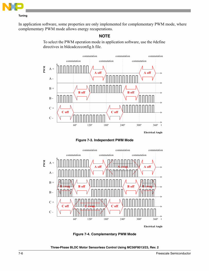
Tuning
Three-Phase BLDC Motor Sensorless Control Using MC56F8013/23, Rev. 2
7-6 Freescale Semiconductor
In application software, some properties are only implemented for complementary PWM mode, where complementary PWM mode allows energy recuperations.
NOTETo select the PWM operation mode in application software, use the #define directives in bldcadczcconfig.h file.
Figure 7-3. Independent PWM Mode
Figure 7-4. Complementary PWM Mode
A +
A -
B +
B -
C +
C -
t 60°
A off A off
B off B off
C off C off
120° 180° 240° 300° 360°
commutation commutation commutation
commutation commutation commutation
Electrical Angle
PWM
B swap B swap
A swapA +
A -
B +
B -
C +
C -
t 60°
A off A off
B off B off
C off C off
120° 180° 240° 300° 360°
commutation commutation commutation
commutation commutation commutation
Electrical Angle
PWM
C swap

Tuning
Three-Phase BLDC Motor Sensorless Control Using MC56F8013/23, Rev. 2
Freescale Semiconductor 7-7
7.4 Power Stage Related ParametersParameters for desired power stage can be loaded by calling one of the following functions:
• EVM33395 Board Settings• MP Board Settings
Unused functions are dead-stripped by the compiler so it does not occupy program flash.
To select the desired power stage board, use #define directives in bldczcconfig.h header file.
7.4.1 Parameters Summary
The parameters in group 2 are listed and explained in Table 7-3.
7.4.2 APP_VOLT_MAX
The value corresponds to the maximum of A/D converter DC-bus voltage reading range.
As an example, if A/D converter high reference is set to 3.3 V, this means A/D converter output is at maximum when 3.3 V is received from its input. If the external analog sampling circuit provides 3.3 V to A/D converter when the DC-bus voltage is 16.0 V, this parameter should be 16.0.
This parameter should be defined by decimal point to enable pre-compiler to make floating point operations.
Table 7-3. Power Stage Related Parameters Summary
Name Description Units Range DefaultFreeMaster
Location
APP_VOLT_MAX DC-bus voltage value, then maximum output is received from A/D Converter.
Volts Defined by board components. No range.
16.3 N/A
APP_CUR_MAX DC-bus current value, then maximum output is received from A/D Converter.
Ampers Defined by board components. No range.
8.25 N/A
DC_UNDERVOLTAGE DC under-voltage level of application. Volts 0.0 – 8.0 5.0 N/A
DC_OVERVOLTAGE DC over-voltage level of application. Volts 13.0 – 16.2 15.0 N/A
DC_OVERCURRENT DC over-current level of application. Ampers 0.0 – 8.25 3.0 N/A

Tuning
Three-Phase BLDC Motor Sensorless Control Using MC56F8013/23, Rev. 2
7-8 Freescale Semiconductor
7.4.3 APP_CUR_MAX
The value corresponds to the maximum A/D converter DC-bus current reading range.
As an example, if A/D converter high reference is set to 3.3 V, this means A/D converter output is at maximum when 3.3 V is received from its input. If the external analog sampling circuit provides 3.3 V to A/D converter when the DC-bus current is 4.0 A, this parameter should be 4.0.
This parameter should be defined by decimal point to enable pre-compiler to make floating point operations.
7.4.4 DC_UNDERVOLTAGE
The DC_Undervoltage fault is triggered from A/D converter when DC-bus voltage drops below this value and the application switches to fault state. An indication LED is also enabled on FreeMASTER page.
7.4.5 DC_OVERVOLTAGE
The DC_Overvoltage fault is triggered from A/D converter when DC-bus voltage exceeds this value and the application switches to fault state. An indication LED is also enabled on FreeMASTER page.
7.4.6 DC_OVERCURRENT
The DC_Overcurrent fault is triggered from A/D converter when DC-bus current exceeds this value and the application switches to fault state. An indication LED is also enabled on FreeMASTER page.
7.5 Motor Related ParametersThe parameters in group three can be divided into sub-group.
• Alignment parameters• Start parameters• Run parameters• General motor and zero cross parameters• Controller parameters
— Speed PI controller— Alignment current PI controller— Current limitation PI controller
As described above, parameters for desired motor can be loaded by calling one of the following functions:• MotorA //IB23811 Motor• MotorB //N2311 Motor
Unused functions are dead-stripped by the compiler so it does not occupy program flash.
To select the desired motor, use #define directives in bldczcconfig.h header file.

Tuning
Three-Phase BLDC Motor Sensorless Control Using MC56F8013/23, Rev. 2
Freescale Semiconductor 7-9
7.5.1 Alignment Parameters
7.5.1.1 Parameters Summary
Parameters for alignment are listed and explained in Table 7-4.
7.5.1.2 PER_ALIGNMENT_S
The duration of the alignment state must be long enough to stabilize the motor, before it starts.
For tuning, it is recommended to keep the alignment duration long enough. After the motor is aligned properly, this duration can be shortened as long as it enables proper alignment.
7.5.1.3 CUR_ALIGN_DESIRED_A
The alignment current PI controller tries to keep the DC-bus current in this value, during alignment commutation state.
The alignment current can be as high as the nominal current of motor.
7.5.1.4 ALIGNMENT_STEP_CMP_ABC
This parameter can vary from 0 to 5, where every value corresponds to a PWM pattern, as following:1. 0 : Atop Bbottom2. 1 : Bbottom Ctop3. 2 : Ctop Abottom4. 3 : Abottom Btop5. 4 : Btop Cbottom6. 5 : Cbottom Atop
These patterns are defined by BldcZC_Cmt_StepTable array in bldcdrv.c.
Table 7-4. Alignment Parameters Summary
Name Description Units Range DefaultFreeMaster
Location
PER_ALIGNMENT_S Duration of alignment commutation state.
Seconds 0.1 – 12.0 0.5 Control > Alignment
CUR_ALIGN_DESIRED_A Alignment current. Ampers 0.1 – 3.0 1.5 Control > Alignment
ALIGNMENT_STEP_CMP_ABC PWM pattern applied to motor at alignment state, when the desired speed is positive.
N/A 0 [A + B−] – 5 [A + C−]
5 [A + C−] Control > Alignment
ALIGNMENT_STEP_CMP_ACB PWM pattern applied to motor at alignment state, when the desired speed is negative.
N/A 0 [A + B−] – 5 [A + C−]
4 [B + C−] Control > Alignment

Tuning
Three-Phase BLDC Motor Sensorless Control Using MC56F8013/23, Rev. 2
7-10 Freescale Semiconductor
7.5.1.5 ALIGNMENT_STEP_CMP_ACB
This parameter can vary from 0 to 5, where every value corresponds to a PWM pattern, as following:1. 0 : Atop Bbottom2. 1 : Bbottom Ctop3. 2 : Ctop Abottom4. 3 : Abottom Btop5. 4 : Btop Cbottom6. 5 : Cbottom Atop
These patterns are defined by BldcZC_Cmt_StepTable array in bldcdrv.c.
7.5.2 Start Parameters
7.5.2.1 Parameters Summary
Parameters for start are listed and explained in Table 7-5.
Changing these parameters in FreeMASTER environment does not affect the application until stopping and restarting the motor.
Table 7-5. Start Parameters Summary
Name Description Units Range DefaultFreeMaster
Location
PER_START_PROCCMT_US
Minimum value for Toff period. Micro seconds
50.0 – 30000.0 170.0 Control > Start
PER_CMTSTART_US Commutation period used to compute the first (start) commutation period
Micro seconds
50.0 – 30000.0 3600.0 Control > Start
PER_TOFFSTART_US First (start) Toff interval after commutation (where back-EMF zero crossing is not sensed).
Micro seconds
50.0 – 30000.0 7200.0 Control > Start
COEF_START_CMT_PRECOMP_FRAC
Coefficient for calculating preset commutation period
Frac FRAC16(0.1) – FRaC16(0.9)
FRAC16(0.5) Control > Start
COEF_START_CMT_PRECOMP_LSHFT
Coefficient for calculating preset commutation period
N/A 1 – 4 2 Control > Start
COEF_START_HLFCMT Coefficient for calculating commutation period (where back-EMF zero crossing is not sensed).
Frac FRAC16(0.1) – FRAC16(0.9)
FRAC16(0.125) Control > Start
COEF_START_TOFF Coefficient for calculating Toff period (where back-EMF zero crossing is not sensed during start).
Frac FRAC16(0.1) – FRAC16(0.5)
FRAC16(0.250) Control > Start
MIN_ZCROSOK_START Minimal number of zero crossing OK commutation to finish the BLDC starting phase.
N/A 2 – 20 2 Control > Start

Tuning
Three-Phase BLDC Motor Sensorless Control Using MC56F8013/23, Rev. 2
Freescale Semiconductor 7-11
7.5.2.2 PER_START_PROCCMT_US
This value limits Toff period to a minimum. Therefore, Toff period applied after every commutation can be a minimum PER_START_PROCCMT_US.
7.5.2.3 PER_CMTSTART_US
There is no zero cross detected during start commutation state. Therefore, the commutation algorithm should predict a value for commutation period and start the process. This value is used for this purpose, as the first predicted commutation period.
For selection of this value, please see Table 7-6.
7.5.2.4 PER_TOFFSTART_US
Similar to PER_CMTSTART_US, this value is the first predicted Toff period duration for Start commutation state.
Setting these constants is an experimental process. It is difficult to use a precise formula because there are many factors involved that are difficult to obtain in case of real drive (motor and load mechanical inertia, motor electromechanical constants, and sometimes also the motor load). Therefore, constants need to be set for a specific motor. Table 7-6 aids in the setting of constants.
Slowing down the speed regulator helps if a problem with start up (using the above stated setting) is encountered.
7.5.2.5 COEF_START_CMT_PRECOMP_FRAC
With COEF_START_CMT_PRECOMP_LSHFT, this coefficient built the COEF_START_CMT_PRECOMP as following:
By the help of this shift operation, it is possible to have the commutation period value bigger than FRAC16(1.0).
This constant has the same function with COEF_RUN_CMT_PRECOMP_FRAC, where one is for run commutation stage and one is for start commutation state.
Table 7-6. Recommended Start Periods
Motor sizex_PER_CMTSTART_US
[μs]x_PER_TOFFSTART_US
[μs]First commutation
period [s]
Slow motor/high load motor mechanical inertia
> 5000 > 10000 > 10ms
Fast motor/high load motor mechanical inertia
< 5000 < 10000 < 10ms
CoefStartCmtPrecomp CoefStartCmtPrecpFrac CoefStartCmtPreCompLshft«=

Tuning
Three-Phase BLDC Motor Sensorless Control Using MC56F8013/23, Rev. 2
7-12 Freescale Semiconductor
7.5.2.6 COEF_START_CMT_PRECOMP_LSHFT
With COEF_START_CMT_PRECOMP_FRAC, this coefficient built the COEF_START_CMT_PRECOMP.
These constant has the same function with COEF_RUN_CMT_PRECOMP_LSHFT, where one is for run commutation stage and one is for start commutation state.
7.5.2.7 COEF_START_HLFCMT
This constant has the same function with COEF_RUN_HLFCMT, where one is for run commutation state and one is for start commutation state.
7.5.2.8 COEF_START_TOFF
This constant has the same function with COEF_RUN_TOFF, where one is for run commutation state and one is for start commutation state.
7.5.2.9 MIN_ZCROSOK_START
After this amount of zero crossing is detected, start commutation state is finished and run commutation state begins.
7.5.3 Run Parameters
7.5.3.1 Parameters Summary
Parameters for run are listed and explained in Table 7-7.Table 7-7. Run Parameters Summary
Name Description Units Range DefaultFreeMaster
Location
PER_RUN_PROCCMT_US Minimum value for Toff period.
micro seconds
50.0 – 30000.0 170.0 Control > Run
COEF_RUN_CMT_PRECOMP_FRAC
Coefficient for calculating preset commutation period
Frac FRAC16(0.1) – FRAC16(0.9)
FRAC16 (0.5) Control > Run
COEF_RUN_CMT_PRECOMP_LSHFT
Coefficient for calculating preset commutation period
N/A 1 – 4 2 Control > Run
COEF_RUN_HLFCMT Coefficient for calculating commutation period, after zero cross detected
Frac FRAC16(0.1) – FRAC16(0.9)
FRAC16(0.5) Control > Run
COEF_RUN_TOFF Coefficient for calculating Toff period
Frac FRAC16(0.1) – FRAC16(0.5)
FRAC16(0.250) Control > Run
MAX_ZCROSERR Maximum commutation period counts with no zero cross detection, to stop the commutation
N/A 2 – 30 4 Control > Run

Tuning
Three-Phase BLDC Motor Sensorless Control Using MC56F8013/23, Rev. 2
Freescale Semiconductor 7-13
Changing these parameters in FreeMASTER environment does not affect the application until stopping and restarting the motor.
7.5.3.2 PER_RUN_PROCCMT_US
This value is used to limit Toff period to a minimum. Therefore, Toff period applied after every commutation can be a minimum PER_RUN_PROCCMT_US.
7.5.3.3 COEF_RUN_CMT_PRECOMP_FRAC
With COEF_RUN_CMT_PRECOMP_LSHFT, this coefficient built the COEF_RUN_CMT_PRECOMP as following:
The preset period is calculated after every commutation, as a default commutation period, if no zero crossing is detected in the next commutation period. If no zero cross is detected until preset commutation period expires, commutation is performed. Otherwise, if zero cross is detected before preset commutation time is expired, the next commutation time is updated and preset commutation time is no more used.
Figure 7-5. COEF_RUN_CMT_PRECOMP Usage
By the help of this shift operation, the commutation period value can be bigger than FRAC16(1.0).
7.5.3.4 COEF_RUN_CMT_PRECOMP_LSHFT
With COEF_RUN_CMT_PRECOMP_FRAC, this coefficient built the COEF_RUN_CMT_PRECOMP.
CoefRunCmtPrecomp CoefRunCmtPrecpFrac CoefRunCmtPreCompLshft«=
Per_ZCros Per_ZCros0
Inside SetCalculation
Per_ZCros0
Per_ZCrosFlt = ( Per_ZCros + PerZCros0 ) / 2 Inside PresetCalculation if ( Per_ZCrosFlt * COEF_RUN_CMT_PRECOMP_FRAC * 2 ^ COEF_RUN_CMT_PRECOMP_LSHFT) < Max_PerCmt
Per_CmtPreset = Per_ZCrosFlt * COEF_RUN_CMT_PRECOMP_FRAC * 2 ^ COEF_RUN_CMT_PRECOMP_LSHFT else Per_CmtPreset = Max_PerCmt
In the next incoming commutation (CmtTimeOut) Next cmt time = T_Cmt0 + Per_CmtPreset
T_ZCros0 T_Cmt0
Zero Cross Signal
Commutation
No ZeroCross detected and commutation performed
according to Per_CmtPreset
Per_CmtPreset

Tuning
Three-Phase BLDC Motor Sensorless Control Using MC56F8013/23, Rev. 2
7-14 Freescale Semiconductor
7.5.3.5 COEF_RUN_HLFCMT
Coefficient for calculating commutation period, after zero cross detected, as described in Figure 7-6.
Figure 7-6. COEF_RUN_HLFCMT Usage
7.5.3.6 COEF_RUN_TOFF
After every commutation, zero crossing sensing is disabled for a Toff period. This period is calculated by help of COEF_RUN_TOFF, as described in Figure 7-7.
As seen, Toff period applied after the commutation has a minimum limit.
Per_ZCros Per_ZCros0
Inside SetCalculation Per_ZCrosFlt = ( Per_ZCros + PerZCros0 ) / 2 Per_HlfCmt = Per_ZCrosFlt * COEF_RUN_HLFCMT After determining ZeroCross time (bldczcZCrosEdgeIntAlg or ZCToffTimeout) Next Cmt Time = T_ZCros + Per_Hlf_Cmt
T_ZCros0 Next Cmt Time
Zero Cross Signal
Commutation
Per__Hlf_Cmt

Tuning
Three-Phase BLDC Motor Sensorless Control Using MC56F8013/23, Rev. 2
Freescale Semiconductor 7-15
Figure 7-7. COEF_RUN_TOFF usage
7.5.3.7 MAX_ZCROSERR
This constant controls commuting problems. If no zero cross is detected for MAX_ZCROSERR commutation cycle, application switches to the stop commutation state and tries for a new alignment, if allowed by the run/stop status.
During tuning of the software for other motors, this constant can temporarily be enlarged.
7.5.4 General Parameters
7.5.4.1 Parameters Summary
These parameter are generally related witch the motor. They are listed and explained in Table 7-8.
Per_ZCros Per_ZCros0
Inside SetCalculation Per_ZCrosFlt = ( Per_ZCros + PerZCros0 ) / 2 if ( Per_ZCrosFlt * COEF_RUN_TOFF ) > Const_PerProcCmt
Per_Toff = Per_ZCrosFlt * COEF_RUN_TOFF
else Per_Toff = Const_PerProcCmt
In the next incoming commutation (CmtTimeOut) Toff expire time = T_Cmt0 + Per_Toff
T_ZCros0 T_Cmt0
Zero Cross Signal
Commutation
Toff expire time
Per_Toff
Where; T_Cmt[n] : Time for commutation for step n. T_Next[n] (cmt) : Time of the next commutation for step n T_ZCros[n] : Time of the zero crossing for step n T_zCros0[n] : Time of the previous zero crossing for step n Per_Toff[n+1] : Period of the Toff duration to be applied at step n+1 Per_CmtPreset : Preset Commutation Periof from commutation to next commutation if no Zero Crossing was captured Per_ZCros[n] : Period between last 2 Zero Crossings for step n Per_ZCros0[n] : Previous period between Zero Crossings for step n Per_ZCrosFlt : Estimated period of commutation filtered for step n Per_HlfCmt : Period from Zero Crossing to commutation (half commutation)

Tuning
Three-Phase BLDC Motor Sensorless Control Using MC56F8013/23, Rev. 2
7-16 Freescale Semiconductor
7.5.4.2 SPEED_ROTOR_MAX_RPM
7.5.4.3 MOTOR_COMMUTATION_PREV
This value must be set according the motor pole size.
7.5.4.4 OMEGA_MIN_SYSU
If the adjusted speed or actual speed of motor is below this value, motor is stopped.
7.5.4.5 CURR_LIMIT_DESIRED_A
The DC-bus current is limited above this value. If the DC-bus current is higher that this value, PWM duty cycle is limited until DC-bus current drops again this value.
The current limitation is active on alignment and running commutation states. If current limiting is dominating output, an alarm signal is also generated.
This parameter can also set from the DC-bus current gauge of the FreeMASTER page.
7.5.5 Controller Parameters
BLDC sensorless application contains three PI controllers.• Speed controller – to keep the motor speed in desired value. Is active only at running.• Alignment current controller – to keep the alignment current in desired value. Active only during
alignment.• Current limitation controller – to keep the DC-bus current below a desired value. Active during
alignment and running.
All three PI controllers have the same structure. Their proportional gain and integral gain can be adjusted, as in every PI controller.
Table 7-8. General Parameters Summary
Name Description Units Range DefaultFreeMaster
Location
SPEED_ROTOR_MAX_RPM Maximum mechanical rotor speed.
RPM Defined by motor design, no range
2000 N/A
MOTOR_COMMUTATION_PREV Number of commutations per revolution.
N/A Defined by motor design, no range
12 N/A
OMEGA_MIN_SYSU Minimum speed. Frac 0 – 6553 3276 N/A
CURR_LIMIT_DESIRED_A Desired current limitation value for DC-bus.
A 0.1 – 4.0 4.0 Control > Current Limiting
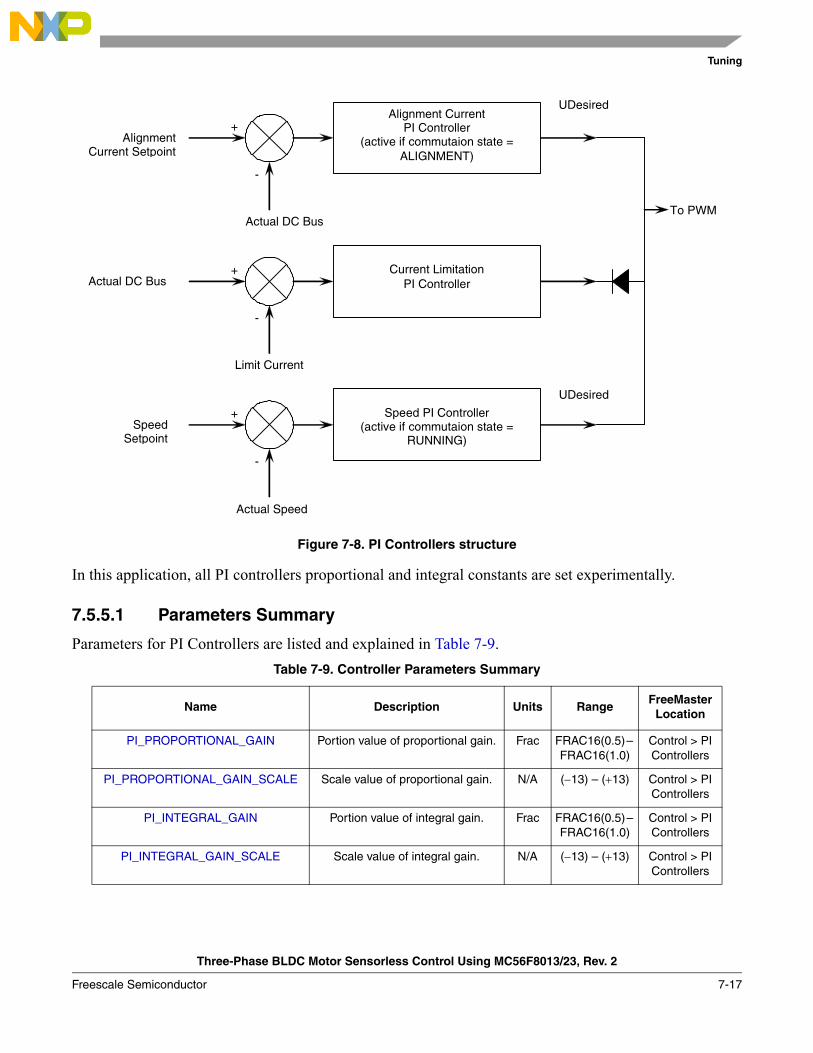
Tuning
Three-Phase BLDC Motor Sensorless Control Using MC56F8013/23, Rev. 2
Freescale Semiconductor 7-17
Figure 7-8. PI Controllers structure
In this application, all PI controllers proportional and integral constants are set experimentally.
7.5.5.1 Parameters Summary
Parameters for PI Controllers are listed and explained in Table 7-9.Table 7-9. Controller Parameters Summary
Name Description Units RangeFreeMaster
Location
PI_PROPORTIONAL_GAIN Portion value of proportional gain. Frac FRAC16(0.5) – FRAC16(1.0)
Control > PI Controllers
PI_PROPORTIONAL_GAIN_SCALE Scale value of proportional gain. N/A (−13) – (+13) Control > PI Controllers
PI_INTEGRAL_GAIN Portion value of integral gain. Frac FRAC16(0.5) – FRAC16(1.0)
Control > PI Controllers
PI_INTEGRAL_GAIN_SCALE Scale value of integral gain. N/A (−13) – (+13) Control > PI Controllers
Speed PI Controller(active if commutaion state =
RUNNING)
+
-
Speed Setpoint
Actual Speed
UDesired
Current LimitationPI Controller
+
-
Limit Current
Alignment CurrentPI Controller
(active if commutaion state = ALIGNMENT)
+
-
Alignment Current Setpoint
Actual DC Bus
UDesired
Actual DC Bus
To PWM
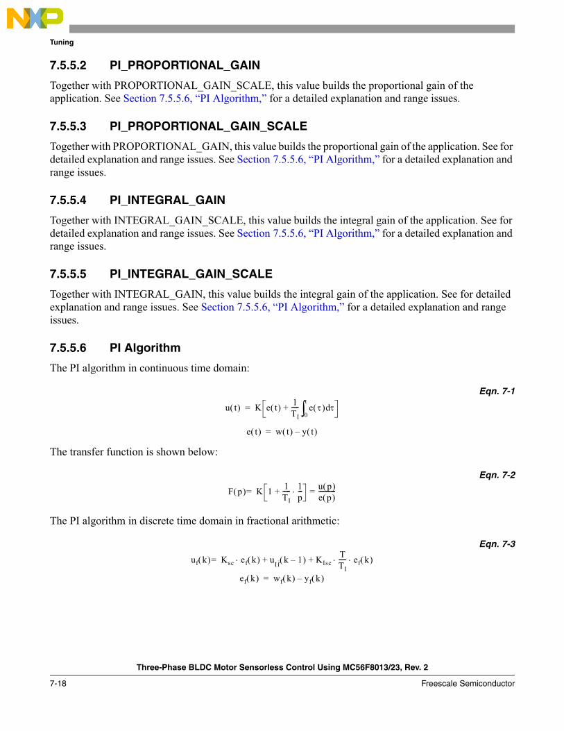
Tuning
Three-Phase BLDC Motor Sensorless Control Using MC56F8013/23, Rev. 2
7-18 Freescale Semiconductor
7.5.5.2 PI_PROPORTIONAL_GAIN
Together with PROPORTIONAL_GAIN_SCALE, this value builds the proportional gain of the application. See Section 7.5.5.6, “PI Algorithm,” for a detailed explanation and range issues.
7.5.5.3 PI_PROPORTIONAL_GAIN_SCALE
Together with PROPORTIONAL_GAIN, this value builds the proportional gain of the application. See for detailed explanation and range issues. See Section 7.5.5.6, “PI Algorithm,” for a detailed explanation and range issues.
7.5.5.4 PI_INTEGRAL_GAIN
Together with INTEGRAL_GAIN_SCALE, this value builds the integral gain of the application. See for detailed explanation and range issues. See Section 7.5.5.6, “PI Algorithm,” for a detailed explanation and range issues.
7.5.5.5 PI_INTEGRAL_GAIN_SCALE
Together with INTEGRAL_GAIN, this value builds the integral gain of the application. See for detailed explanation and range issues. See Section 7.5.5.6, “PI Algorithm,” for a detailed explanation and range issues.
7.5.5.6 PI Algorithm
The PI algorithm in continuous time domain:
Eqn. 7-1
The transfer function is shown below:
Eqn. 7-2
The PI algorithm in discrete time domain in fractional arithmetic:
Eqn. 7-3
u t( ) K e t( ) 1TI----- e τ( ) τd
0
τ
∫+=
e t( ) w t( ) y t( )–=
F p( ) K 1 1TI----- 1
p---⋅+ u p( )
e p( )-----------==
uf k( ) Ksc ef k( ) uIf k 1–( ) KIscTTI----- ef k( )⋅ ⋅+ +⋅=
ef k( ) wf k( ) yf k( )–=
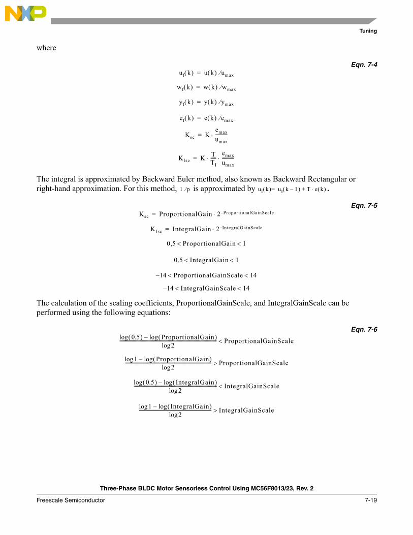
Tuning
Three-Phase BLDC Motor Sensorless Control Using MC56F8013/23, Rev. 2
Freescale Semiconductor 7-19
where
Eqn. 7-4
The integral is approximated by Backward Euler method, also known as Backward Rectangular or right-hand approximation. For this method, is approximated by .
Eqn. 7-5
The calculation of the scaling coefficients, ProportionalGainScale, and IntegralGainScale can be performed using the following equations:
Eqn. 7-6
uf k( ) u k( ) umax⁄=
wf k( ) w k( ) wmax⁄=
yf k( ) y k( ) ymax⁄=
ef k( ) e k( ) emax⁄=
Ksc Kemax
umax-----------⋅=
KIsc K TTI-----
emax
umax-----------⋅ ⋅=
1 p⁄ uI k( ) uI k 1–( ) T e k( )⋅+=
Ksc ProportionalGain 2 ProportionalGainScale–⋅=
KIsc IntegralGain 2 IntegralGainScale–⋅=
0 5, ProportionalGain 1< <
0 5, IntegralGain 1< <
14– ProportionalGainScale 14< <
14– IntegralGainScale 14< <
0.5( )log ProportionalGain( )log–2log
-------------------------------------------------------------------------------------- ProportionalGainScale<
1log ProportionalGain( )log–2log
----------------------------------------------------------------------------- ProportionalGainScale>
0.5( )log IntegralGain( )log–2log
-------------------------------------------------------------------------- IntegralGainScale<
1log IntegralGain( )log–2log
---------------------------------------------------------------- IntegralGainScale>
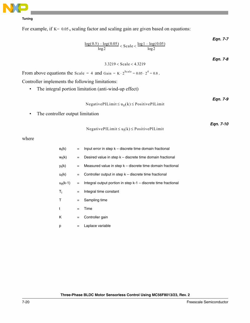
Tuning
Three-Phase BLDC Motor Sensorless Control Using MC56F8013/23, Rev. 2
7-20 Freescale Semiconductor
For example, if , scaling factor and scaling gain are given based on equations:
Eqn. 7-7
Eqn. 7-8
From above equations the and .
Controller implements the following limitations:• The integral portion limitation (anti-wind-up effect)
Eqn. 7-9
• The controller output limitation
Eqn. 7-10
where
ef(k) = Input error in step k – discrete time domain fractional
wf(k) = Desired value in step k – discrete time domain fractional
yf(k) = Measured value in step k – discrete time domain fractional
uf(k) = Controller output in step k – discrete time fractional
uIf(k-1) = Integral output portion in step k-1 – discrete time fractional
TI = Integral time constant
T = Sampling time
t = Time
K = Controller gain
p = Laplace variable
K 0.05=
0.5( )log 0.05( )log–2log
-------------------------------------------------- Scale 1log 0.05( )log–2log
----------------------------------------< <
3.3219 Scale 4.3219< <
Scale 4= Gain K 2Scale 0.05 24 0.8=⋅=⋅=
NegativePILimit uIf≤ k( ) PositivePILimit≤
NegativePILimit uf≤ k( ) PositivePILimit≤
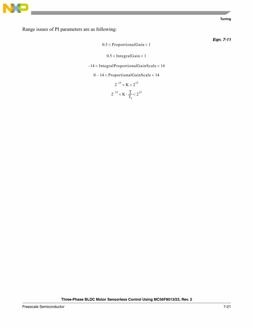
Tuning
Three-Phase BLDC Motor Sensorless Control Using MC56F8013/23, Rev. 2
Freescale Semiconductor 7-21
Range issues of PI parameters are as following:
Eqn. 7-110.5 ProportionalGain 1< <
0.5 IntegralGain 1< <
14– IntegralProportionalGainScale 14< <
0 14– ProportionalGainScale 14< <
2 15– K 215< <
2 15– K< TTI-----⋅ 215<

Tuning
Three-Phase BLDC Motor Sensorless Control Using MC56F8013/23, Rev. 2
7-22 Freescale Semiconductor
Three-Phase BLDC Motor Sensorless Control Using MC56F8013/23, Rev. 2
Freescale Semiconductor A-1
Appendix A GlossaryAC — alternating current
A/D converter — analog-to-digital converter
Back-EMF — back electro-motive force. In this document, it means the voltage is induced into motor winding due to rotor movement.
Brush — a component transferring electrical power from non-rotational terminals, mounted on the stator, to the rotor
BLDC — brushless DC motor
Commutation — a process providing the creation of a rotation field by switching of power transistor (electronic replacement of brush and commutator)
Commutator — a mechanical device alternating DC current in DC commutator motor and providing rotation of DC commutator motor
COP — computer operating properly timer
DC — direct current
DC-bus — part of power converter with direct current
DC motor — direct current motor, if not mentioned differently, it means the motor with brushes.
DSP — digital signal processor
DSC — digital signal controller
Dead time (DT) — short time that must be inserted between the turning off of one transistor in the inverter half-bridge and turning on of the complementary transistor due to the limited switching speed of the transistors
Duty cycle — a ratio of the amount of time the signal is on versus the time it is off. Duty cycle is usually represented by a percentage.
GPIO — general purpose input/output
Hall sensors — a position sensor giving six defined events (each 60 electrical degrees) per electrical revolution (for three-phase motor)
HV — high voltage (115 V AC or 230 V AC)
Interrupt — a temporary break in the sequential execution of a program to respond to signals from peripheral devices by executing a subroutine

Glossary
Three-Phase BLDC Motor Sensorless Control Using MC56F8013/23, Rev. 2
A-2 Freescale Semiconductor
Input/Output (I/O) — input/output interfaces between a computer system and the external world. A CPU reads an input to sense the level of an external signal and writes to an output to change the level on an external signal
JTAG — interface allowing on-chip emulation and programming
Logic 1 — a voltage level approximately equal to the input power voltage (VDD)
Logic 0 — a voltage level approximately equal to the ground voltage (VSS)
LV — low voltage (12 V DC)
Processor expert (PE) — integrated development environment for Freescale MC56F8xxx series Digital Signal Controllers
PI controller — proportional-Integral controller
Phase-Locked loop (PLL) — A clock generator circuit in which a voltage controlled oscillator produces an oscillation which is synchronized to a reference signal
PM — permanent magnet
PMSM — permanent magnet synchronous motor
PWM — pulse width modulation
Quadrature decoder — a module providing decoding of position from a quadrature encoder mounted on a motor shaft
Quad timer — a module with four 16-bit timers
Reset — to force a device to a known condition
RPM — revolutions per minute
Serial communications interface module (SCI) — a module that supports asynchronous communication
Serial peripheral interface module (SPI) — a module that supports synchronous communication
Software — instructions and data that control the operation of a microcontroller
Software interrupt (SWI) — an instruction that causes an interrupt and its associated vector fetch
Timer — a module used to relate events in a system to a point in time
Zero crossing (ZC) — instant when back-EMF voltage of a phase crosses half of the DC-bus value.