ISSN 1517-7076 articles e-12612, 2020
Corresponding Author: Sefika Kasman Received on: 28/06/2019 Accepted on: 12/08/2019
10.1590/S1517-707620200002.1012
The Effects of Pin Offset for FSW of
Dissimilar Materials: A Study for
AA 7075 – AA 6013
Sefika Kasman1
1 Dokuz Eylul University, Faculty of Engineering, Department of Mechanical Engineering, Izmir, Turkey.
e-mail: [email protected]
ABSTRACT
The trend in welding of dissimilar aluminum alloys oriented to new application techniques to increase the
functionality and perform the welding procedure without any problem in the welded joints. The pin profile
and process parameters determined for the friction stir welding greatly affect the weldability and strength of
the welded joints. In addition, it is also considered that the pin offset is also an effective factor on the strength
and microstructure of welded joints. In the present study, aluminum alloys AA 6013–T6 and AA 7075–T651
were welded with the FSW process applying pin offset technique. The changes in the mechanical and micro-
structural properties were investigated. The onion ring structure was observed in all of microstructure of weld
stir zone. Except the welded joint fabricated with the tool rotational speed of 400 rpm for both without pin
offset and with offset to retreating side, all the welded joints were fractured at the base metal region and heat
affected zone in AA 6013 alloy. The welded joints fabricated with the tool rotational speed of 400 rpm con-
sisted of small and large cavity-type defects. Although defects were found to occur in the welded joints, none
of the welded joints were fractured at the SZ during the tensile and bending tests. The ultimate tensile
strength and elongation at rupture of the dissimilar FS welded joints were ranged between 164 MPa and 179
MPa, 6.5 and 7.6%, respectively. These defects were found to affect the ductility feature of the welded joints.
The pin offset direction was found to affect the volume of parent materials in the stir zone. Hence, the mate-
rial volume in the onion rings changes and, the hardness distribution is also affected by the changes in the
material volume.
Keywords: aluminum alloys, friction stir welding parameters, fracture analysis
1. INTRODUCTION
Friction stir welding (FSW) is one of the most important solid state welding technique and has attracted at-
tention in the welding of dissimilar materials in recent years. The FSW process presents superior advantages
in comparison to those of conventional fusion welding techniques in achieving sound welded joints [1,2].
During the FSW, no filler material is used. Mismatch problem between the dissimilar materials, solidification
or liquation cracking, formation of porosity, segregation and dendritic structure are eliminated, as well [3].
Solidification cracking in aluminum alloys is accepted as the critical issue due to the consistency between the
filler materials and base materials [4]. The provided advantages of the FSW are accepted crucial in producing
commercial products in the automotive, shipbuilding, marine, aircraft industries. Some of aluminum alloys
used in those industries need special care during the welding process. Especially, fusion welding of the dis-
similar materials is difficult in comparison to welding of similar materials. The FSW process occurs in the
solid phase of the materials, thus eliminating most of the problems occurred in the fusion welding.
All the researches related to the FSW have received great attention due to the newly studied materials
or material couples. Variety of tool pin profiles and process parameters, selection of the placement side of the
material in dissimilar FSW and tool offset to the side of the tool pin in the single pass weld seam are also
crucial in obtaining welded joints with high mechanical strength and ductility. Most of those studies have
concentrated on improving mechanical and metallurgical properties of the welded joints [5]. The studied
aluminum alloys are mostly 2xxx, 5xxx, 6xxx and 7xxx series. However, dissimilar welding of AA 6xxx
alloy and AA 7xxx alloy is frequently investigated. The effects of placement of the tool, which offsets the
seam to the advancing side (AS) or retreating side (RS) of pin, and welding parameters, namely tool rotation-
al speed (TRS) and welding speed (WS), on the dissimilar welding of 6061-T6 and 7075-T6 alloys were
studied by Cole et. al. [6]. In that study, the single pass weld seam was performed for the FSW applications.
KASMAN, S. revista Matéria, v. 25, n. 2, 2020.
The tensile strength increased when the tool was offset into the RS of AA 7075 alloy. This placement
of the tool helps in decreasing the average heat occurred during the welding process. Researchers [7-17]
studied the FSW ability of dissimilar aluminum alloys AA 6xxx and AA 7xxx to determine the effect of FS
welding parameters on the strength and microstructure of welded joints. In these studies, it was revealed that
the placement of the metals on each side of pin and welding parameters exhibited a significant impact on
formation of defects and microstructural evolution of the weld stir zone (SZ) structure.
In the present study, the selected material couples are AA 6013 – T6 and AA 7075 – T651 alloys. AA
6013 alloy (AlMg1Si0.8CuMn) is a medium strength aluminum alloy which exhibits good stress corrosion
resistance, stretch formability and lower density. The AA 6013 alloy is among the primary materials used as
aircraft structures, aerospace application and fuselage panels [2]. AA 7075 alloy (AlZn5.5MgCu) aluminum
alloy exhibits higher strength in comparison to that of AA 6013 alloy. AA 7075 is generally used in aircraft
and structural engineering applications. While the temper condition for AA 7075 is solution heat treated,
stress relieved by stretching then artificially aged (T651), the temper condition for AA 6013 is solution heat
treated and artificially aged (T6). T651 and T6 have the same properties, but they are not the same temper
procedure. T651 temper is a stress relieved version of T6 temper. In the present study, two different alumi-
num alloys have different temper procedure. These cause the change in both of the tensile properties and
hardness. Both of the tensile properties and hardness of AA 7075 alloy is greater than those of AA 6013
alloy. AA 7075 alloy is generally used in aircraft and structural engineering applications. The welding of
dissimilar materials with unique features will lead to producing creative structures with specially designed
engineering properties [18]. The new trend in the engineered structures is to provide multi functions, such as
resistance to corrosion, high temperature and wear. The technological emerging in manufacturing of engi-
neered components may lead to evolving towards production of the hybrid structures in the near future [19].
So that, it is considered that the above mentioned materials and selected welding parameters for the present
study will offer a new trend in terms of functionality of an engineering components.
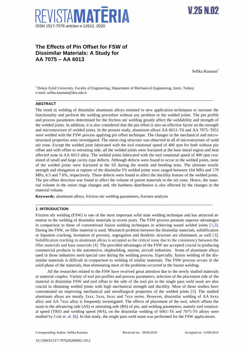
In this study, the multi-pass weld seams were formed by pin offset (PO) technique. The schematic il-
lustration of multi-pass weld seam formed by PO is given in Figure 1. In the weld seam performed with PO
technique, the first weld seam is performed by selecting FSW parameters and the second weld seam is per-
formed with a certain displacement towards AS or RS of the tool pin. It is considered that the defects formed
by the tool pin tip could be eliminated using this method. In the available literature, it has been found that this
method has not been previously investigated or studied by other researchers in FSW applications. Therefore,
the present study has important contributions to the related literature. The main aim of this study is to analyze
the effect of double weld seam produced by the PO and different TRSs on the mechanical and microstructur-
al properties. Notably, there are no similar FSW experiments applied to AA6013 and AA7075 aluminum
alloys using the selected welding conditions in this study.
Figure 1: The schematic illustration of pin offset phenomenon (top view)
KASMAN, S. revista Matéria, v. 25, n. 2, 2020.
2. EXPERIMENTAL PROCEDURES
2.1 Friction stir welding procedure
The plates of AA 6013-T6 and AA7075-T651 alloys of 5 mm thickness were selected as the metal couples
for the dissimilar FS butt welding applications. The chemical and mechanical properties of each alloy are
given in Table 1. Each plate was machined in the size of 100 x 225 mm. Before welding process, the surface
of the plates was brushed to remove the dust. The dissimilar FS butt welding experiments were carried out
with a universal milling machine (6TI3-Russia).
Three different TRSs of 400, 500, 630 rpm and a constant WS of 50 mm/min were selected and ap-
plied to perform the welding process. The selected WS was determined according to the previous experi-
mental studies. During the welding process, a tool consisting of cylindrical shaped shoulder with the diameter
of 18 mm and a special designed pin with shaped as taper cylindrical was used. The threaded pin in 4.95 mm
long is shown in Figure 2b. The biggest and lowest diameters of the pin are 7 mm and 4 mm, respectively.
The FSW process parameters are given in Table 2. The tool was made of H13 hot work tool steel.
Before welding, the plates were placed on a backing plates and fixed by components as shown in Figure 2a.
The tool was tilted as 3° and rotated in the clockwise direction. The placement of the plates was performed
considering the hardness of alloys. The AA 7075 alloy is harder than that of AA 6013 alloy. Therefore, the
AA 7075 and the AA 6013 alloys were placed on the AS and RS, respectively. The first three joints, namely
weld set 1 (WS-1) was fabricated by a single pass welding. In those joints, the tool pin was plunged in the
center of the contact line where the surface of plates was in contact, until the shoulder touched the plate sur-
face. The tool continues to rotate at this position for a certain time (dwell time) to achieve the required weld-
ing temperature. Following the dwell time, the heat is generated for welding and subsequently the tool
movement starts. The other welded joints, namely weld set 2 (WS-2) were fabricated following the single
pass as mentioned above. For the second weld seam, the tool pin was displaced at a specified offset distance
(1 mm) on the first weld seam. Following this step, the weld was initiated in the new weld line. This proce-
dure is named as PO phenomenon and illustrated as shown in Figure 1.
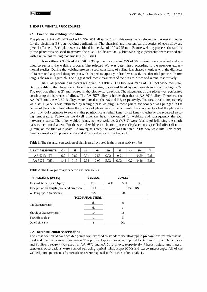
Table 1: The chemical composition of aluminum alloys used in the present study (wt. %)
ALLOY / ELEMENTS Cu Si Mg Mn Zn Ti Cr Fe Al
AA 6013 – T6 0.9 0.89 0.91 0.55 0.02 0.01 - 0.39 Bal.
AA 7075 – T651 1.45 0.15 2.58 0.06 5.72 0.034 0.2 0.16 Bal.
Table 2: The FSW process parameters and their values
PARAMETERS (UNITS) SYMBOL LEVELS
Tool rotational speed (rpm) TRS 400 500 630
Tool pin offset length (mm) and direction PO 0 1mm - RS
Welding speed (mm/min) WS 50
FIXED PARAMETERS
Pin diameter (mm) d1 4
d2 7
Shoulder diameter (mm) D 18
Tool tilt angle (°) α 3
Dwell time (s) t 20s
2.2 Microstructural observations.
The cross section of each welded joints was exposed to standard metallographic preparations for microstruc-
tural and macrostructural observation. The polished specimens were exposed to etching process. The Keller’s
and Poulton’s reagent was used for AA 7075 and AA 6013 alloys, respectively. Microstructural and macro-
structural observations were carried out using optical microscope (OM) and stereo microscope. All of the
welded joint specimens after tensile test were exposed to fracture surface analysis.
KASMAN, S. revista Matéria, v. 25, n. 2, 2020.
2.3 Mechanical testing
The mechanical properties of welded joints were determined by the tensile tests. The tensile test specimens
were machined according to the ASTM E8 M-04 standard. Hydraulic tensile test machine was used to per-
form the tests. The tensile tests were performed at room temperature with a cross-head speed of 2 mm/min.
For each welding conditions, three samples were tensile tested. Bending tests were performed on the root side
of the welded joint. Hence, the root of weld region was exposed to the tensile stress. The test specimens were
prepared in the size of 20 x 150 mm. Three – point root bending tests were performed using 500 kN hydrau-
lic tensile test machine with a cross head speed of 10 mm/min. The bending angle was selected as 90°. Bend-
ing tests were terminated when the bending angle was reached to 90°. The Vickers micro-hardness tests were
performed using a load of 100 g (HV0,1) with a dwell time of 10 s. The hardness measurements were per-
formed on the middle line of cross-section of each welded joint. The measurements were performed at a
distance of 1 mm. The results of the tensile and the bending tests and the values taken from the hardness
measurements were used to evaluate the mechanical properties. Also, the joint efficiency (JE) for each weld-
ed joints was calculated. JE is a factor that characterizes the welding quality and changes as a function of
welding method. JE is expressed as the ratio of the strength of the welded joint to the strength of the base
metal. The scanning electron microscope (SEM) was used to analyze the fracture surface of each welded
joint. The fracture surfaces were analyzed with a JEOL JSM-6060 model SEM.
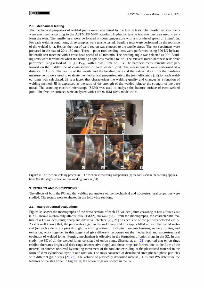
Figure 2: The friction welding procedure; The friction stir welding components (a) the tool used in the welding applica-
tions (b), the stages of friction stir welding process (c-f)
3. RESULTS AND DISCUSSIONS
The effects of both the PO and the welding parameters on the mechanical and microstructural properties were
studied. The results were evaluated in the following sections:
3.1 Macrostructural evaluations
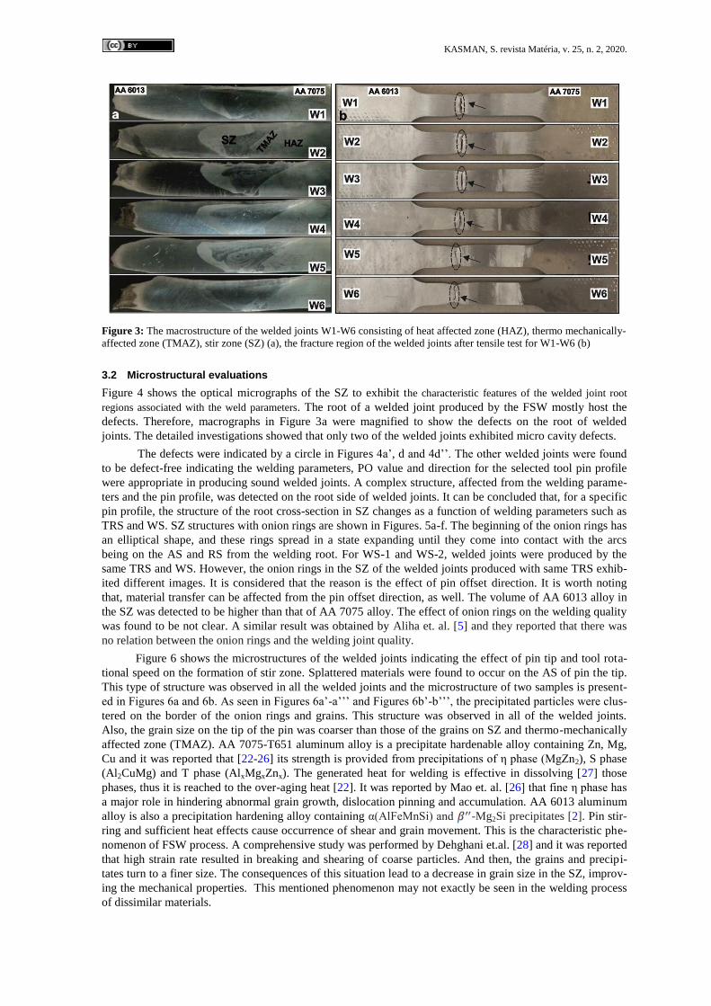
Figure 3a shows the macrographs of the cross section of each FS welded joints consisting of heat affected zone
(HAZ), thermo mechanically-affected zone (TMAZ), stir zone (SZ). From the macrographs, the characteristic fea-
ture of a FS welded joints; sharp and diffusive interface [20, 21] on each side of the pin was detected easily.
As it is well known that, the pin creates a gap in the weld zone and this gap is filled up with the mixed mate-
rial (on each side of the pin) through the stirring action of tool pin. Two mechanisms, namely forging and
extrusion, work together in this stage and give different responses on the mechanical and microstructural
evolution of welded joints. Forging mechanism is effective in the formation of onion rings in the SZ. In this
study, the SZ of all the welded joints consisted of onion rings. Sharma et. al. [22] reported that onion rings
exhibit alternates bright and dark rings (consecutive rings) and those rings are formed due to the flow of the
material in batches occurred by rotating movement of the tool and extruding of the plasticized material in the
form of semi cylindrical layer in one rotation. The rings consisted of distributed strengthened phase particles
with different grain sizes [21-23]. The volume of plastically deformed material, TRS and WS determine the
features of the stirs zone. In Figure 3a, the onion rings are shown in the SZ.
KASMAN, S. revista Matéria, v. 25, n. 2, 2020.
Figure 3: The macrostructure of the welded joints W1-W6 consisting of heat affected zone (HAZ), thermo mechanically-
affected zone (TMAZ), stir zone (SZ) (a), the fracture region of the welded joints after tensile test for W1-W6 (b)
3.2 Microstructural evaluations
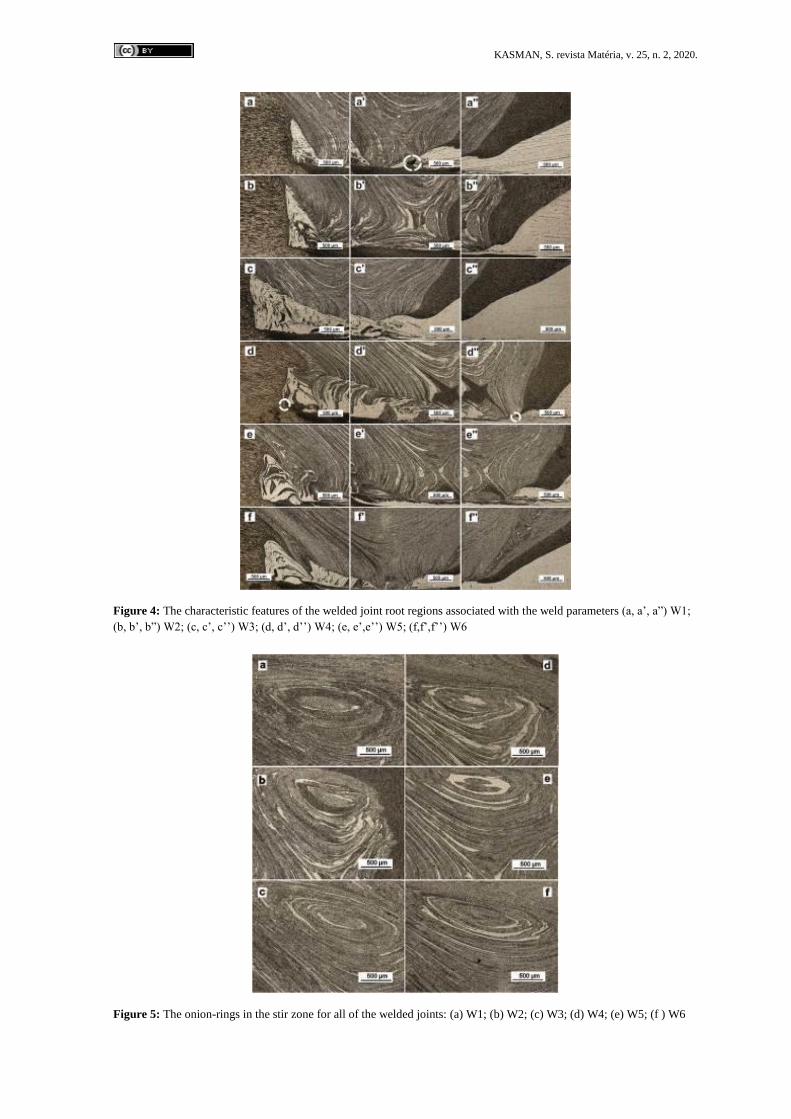
Figure 4 shows the optical micrographs of the SZ to exhibit the characteristic features of the welded joint root
regions associated with the weld parameters. The root of a welded joint produced by the FSW mostly host the
defects. Therefore, macrographs in Figure 3a were magnified to show the defects on the root of welded
joints. The detailed investigations showed that only two of the welded joints exhibited micro cavity defects.
The defects were indicated by a circle in Figures 4a’, d and 4d’’. The other welded joints were found
to be defect-free indicating the welding parameters, PO value and direction for the selected tool pin profile
were appropriate in producing sound welded joints. A complex structure, affected from the welding parame-
ters and the pin profile, was detected on the root side of welded joints. It can be concluded that, for a specific
pin profile, the structure of the root cross-section in SZ changes as a function of welding parameters such as
TRS and WS. SZ structures with onion rings are shown in Figures. 5a-f. The beginning of the onion rings has
an elliptical shape, and these rings spread in a state expanding until they come into contact with the arcs
being on the AS and RS from the welding root. For WS-1 and WS-2, welded joints were produced by the
same TRS and WS. However, the onion rings in the SZ of the welded joints produced with same TRS exhib-
ited different images. It is considered that the reason is the effect of pin offset direction. It is worth noting
that, material transfer can be affected from the pin offset direction, as well. The volume of AA 6013 alloy in
the SZ was detected to be higher than that of AA 7075 alloy. The effect of onion rings on the welding quality
was found to be not clear. A similar result was obtained by Aliha et. al. [5] and they reported that there was
no relation between the onion rings and the welding joint quality.
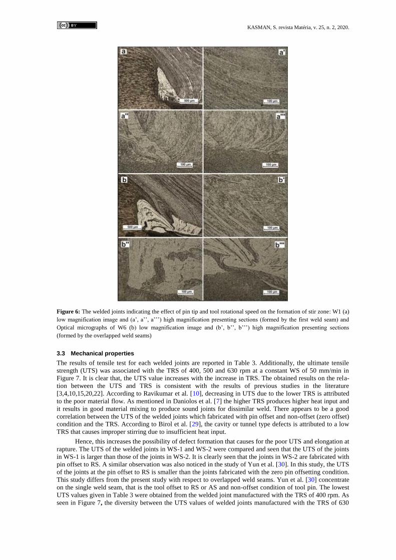
Figure 6 shows the microstructures of the welded joints indicating the effect of pin tip and tool rota-
tional speed on the formation of stir zone. Splattered materials were found to occur on the AS of pin the tip.
This type of structure was observed in all the welded joints and the microstructure of two samples is present-
ed in Figures 6a and 6b. As seen in Figures 6a’-a’’’ and Figures 6b’-b’’’, the precipitated particles were clus-
tered on the border of the onion rings and grains. This structure was observed in all of the welded joints.
Also, the grain size on the tip of the pin was coarser than those of the grains on SZ and thermo-mechanically
affected zone (TMAZ). AA 7075-T651 aluminum alloy is a precipitate hardenable alloy containing Zn, Mg,
Cu and it was reported that [22-26] its strength is provided from precipitations of η phase (MgZn2), S phase
(Al2CuMg) and T phase (AlxMgxZnx). The generated heat for welding is effective in dissolving [27] those
phases, thus it is reached to the over-aging heat [22]. It was reported by Mao et. al. [26] that fine η phase has
a major role in hindering abnormal grain growth, dislocation pinning and accumulation. AA 6013 aluminum
alloy is also a precipitation hardening alloy containing α(AlFeMnSi) and -Mg2Si precipitates [2]. Pin stir-
ring and sufficient heat effects cause occurrence of shear and grain movement. This is the characteristic phe-
nomenon of FSW process. A comprehensive study was performed by Dehghani et.al. [28] and it was reported
that high strain rate resulted in breaking and shearing of coarse particles. And then, the grains and precipi-
tates turn to a finer size. The consequences of this situation lead to a decrease in grain size in the SZ, improv-
ing the mechanical properties. This mentioned phenomenon may not exactly be seen in the welding process
of dissimilar materials.
KASMAN, S. revista Matéria, v. 25, n. 2, 2020.
Figure 4: The characteristic features of the welded joint root regions associated with the weld parameters (a, a’, a”) W1;
(b, b’, b”) W2; (c, c’, c’’) W3; (d, d’, d’’) W4; (e, e’,e’’) W5; (f,f’,f’’) W6
Figure 5: The onion-rings in the stir zone for all of the welded joints: (a) W1; (b) W2; (c) W3; (d) W4; (e) W5; (f ) W6
KASMAN, S. revista Matéria, v. 25, n. 2, 2020.
Figure 6: The welded joints indicating the effect of pin tip and tool rotational speed on the formation of stir zone: W1 (a)
low magnification image and (a’, a’’, a’’’) high magnification presenting sections (formed by the first weld seam) and
Optical micrographs of W6 (b) low magnification image and (b’, b’’, b’’’) high magnification presenting sections
(formed by the overlapped weld seams)
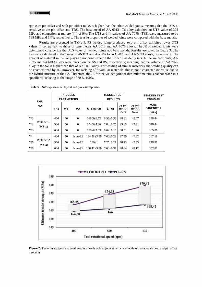
3.3 Mechanical properties
The results of tensile test for each welded joints are reported in Table 3. Additionally, the ultimate tensile
strength (UTS) was associated with the TRS of 400, 500 and 630 rpm at a constant WS of 50 mm/min in
Figure 7. It is clear that, the UTS value increases with the increase in TRS. The obtained results on the rela-
tion between the UTS and TRS is consistent with the results of previous studies in the literature
[3,4,10,15,20,22]. According to Ravikumar et al. [10], decreasing in UTS due to the lower TRS is attributed
to the poor material flow. As mentioned in Daniolos et al. [7] the higher TRS produces higher heat input and
it results in good material mixing to produce sound joints for dissimilar weld. There appears to be a good
correlation between the UTS of the welded joints which fabricated with pin offset and non-offset (zero offset)
condition and the TRS. According to Birol et al. [29], the cavity or tunnel type defects is attributed to a low
TRS that causes improper stirring due to insufficient heat input.
Hence, this increases the possibility of defect formation that causes for the poor UTS and elongation at
rapture. The UTS of the welded joints in WS-1 and WS-2 were compared and seen that the UTS of the joints
in WS-1 is larger than those of the joints in WS-2. It is clearly seen that the joints in WS-2 are fabricated with
pin offset to RS. A similar observation was also noticed in the study of Yun et al. [30]. In this study, the UTS
of the joints at the pin offset to RS is smaller than the joints fabricated with the zero pin offsetting condition.
This study differs from the present study with respect to overlapped weld seams. Yun et al. [30] concentrate
on the single weld seam, that is the tool offset to RS or AS and non-offset condition of tool pin. The lowest
UTS values given in Table 3 were obtained from the welded joint manufactured with the TRS of 400 rpm. As
seen in Figure 7, the diversity between the UTS values of welded joints manufactured with the TRS of 630
KASMAN, S. revista Matéria, v. 25, n. 2, 2020.
rpm zero pin offset and with pin offset to RS is higher than the other welded joints, meaning that the UTS is
sensitive to the pin offset and TRS. The base metal of AA 6013 –T6 alloy exhibited an UTS value of 302
MPa and elongation at rupture (Ꜫf) of 9%. The UTS and Ꜫf values of AA 7075 –T651 were measured to be
588 MPa and 14%, respectively. The tensile properties of welded joints were compared with the base metals.
Results are presented in Table 3. FS welded joints produced zero pin offset exhibited lower UTS
values in comparison to those of base metals AA 6013 and AA 7075 alloys. The JE of welded joints were
determined considering the UTS value of welded joints and base metals. Results are given in Table 3. The
JEs were calculated in the range of 28-31% and 47-51% for AA 7075 and AA 6013 alloys, respectively. The
amount of material in the SZ plays an important role on the UTS of welded joints. In the welded joints, AA
7075 and AA 6013 alloys were placed on the AS and RS, respectively; meaning that the volume of AA 7075
alloy in the SZ is higher than that of AA 6013 alloy. For welding of similar materials, the welding quality can
be characterized by JE. However, for welding of dissimilar materials, this is not a characteristic value due to
the hybrid structure of the SZ. Therefore, the JE for the welded joint of dissimilar materials cannot reach to a
specific value being in the range of 70 %-100%.
Table 3: FSW experimental layout and process responses
EXP.
NO
PROCESS
PARAMETERS
TENSILE TEST
RESULTS
BENDING TEST RESULTS
TRS WS PO UTS (MPa) Ɛf (%) JE (%) for AA 7075
JE (%) for AA 6013
MAX. STRENGTH
(MPa)
W1
Weld set 1
(WS-1)
400 50 0 168.3±1.52 6.55±0.36 28.61 48.07 248.44
W2 500 50 0 174.3±4.96 7.08±0.25 29.65 49.81 348.44
W3 630 50 0 179.4±2.63 6.62±0.15 30.51 51.26 185.86
W4
Weld set 2
(WS-2)
400 50 1mm-RS 164.58±3.39 7.60±0.28 27.99 47.02 267.19
W5 500 50 1mm-RS 166±1 7.25±0.29 28.23 47.43 278.91
W6 630 50 1mm-RS 168.42±3.76 7.60±0.37 28.64 48.12 257.81
Figure 7: The ultimate tensile strength results of each welded joint as associated with tool rotational speed and pin offset
direction
KASMAN, S. revista Matéria, v. 25, n. 2, 2020.
All the welded joints were fractured on the AA 6013 alloy side. Similar results were also obtained
from the dissimilar FSW experiments [5,7,11] on the AA 6XXX and AA 7XXX aluminum alloys. In WS-1,
the volume of AA 7075 alloy was found to be lower than in WS-2. Therefore, the mechanical properties of
AA 6013 alloy dominated the UTS of the welded joints. This conclusion coincides with the results of Ꜫf and
bending strength. The standard deviation of UTS value of welded joints was calculated to be 5.63. Besides,
the standard deviations for both WS-1 and WS-2 were also calculated and found that while the standard devi-
ation was 4.57 for WS-1, it was calculated to be 1.59 for WS-2. The standard deviation value for WS-2
means that the possibility of a defect in the welded joints is almost zero or in small size. In Figures 4 d and
d’’ defects in the SZ are shown. These microstructures were taken from the welded joint manufactured with
TRS of 400 rpm and zero PO and PO to the RS, respectively. These defects lead to increase in the standard
deviation. The standard deviation for W-1 was calculated to be 4.57 and this value is higher than WS-2
(1.59). This difference belongs to the defect size in the welded joint manufactured with TRS of 400 rpm and
zero pin offset. Ꜫf of all welded joints was ranged between 6.55 and 7.60%. As mentioned above, all the
welded joints were fractured on the side of AA 6013 alloy. The Ꜫf of AA 6013 was 9%. When the Ꜫf of
welded joints was compared with AA 6013 alloy base metal, Ꜫf ratio was calculated to be between 72% and
84%.
The fracture location of each joint is presented in Figure 3a, b. As it can be clearly seen all the welded
joints were fractured outside the SZ. The fracture locations were indicated by a circle in Figure 3b. All the
welded joints were fractured in the border of base metal and HAZ (Figure 3a, b). Although defects were
found to be in the welded joints of W1 and W4, fractures were occurring outside the SZ. According to Aliha
et al. [5], the defects produce high stress concentration and these affect the fracture location and formation.
Daniolos et al. [7] indicate that the heterogeneity in the stir zone due to the using of dissimilar materials may
have an effect on the abnormal behavior of the mechanical properties of welded joints. Additionally, it is
though that the bidirectional effect of both the pin offset and placement of materials considering the tool
rotational direction also determines the volume of material in the stir zone and possibility of defect for-
mation. The mechanical properties and the response to the heat input during welding of two materials have a
role on the defect formations and joint characteristics.
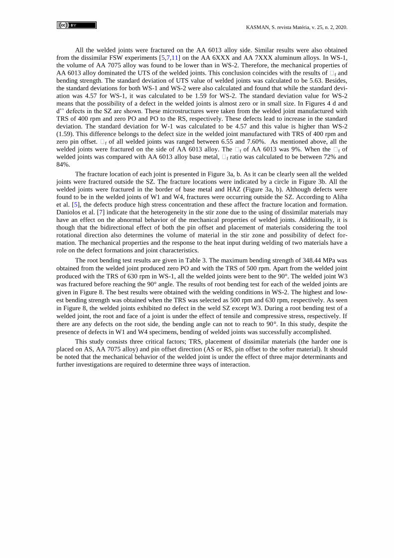
The root bending test results are given in Table 3. The maximum bending strength of 348.44 MPa was
obtained from the welded joint produced zero PO and with the TRS of 500 rpm. Apart from the welded joint
produced with the TRS of 630 rpm in WS-1, all the welded joints were bent to the 90°. The welded joint W3
was fractured before reaching the 90° angle. The results of root bending test for each of the welded joints are
given in Figure 8. The best results were obtained with the welding conditions in WS-2. The highest and low-
est bending strength was obtained when the TRS was selected as 500 rpm and 630 rpm, respectively. As seen
in Figure 8, the welded joints exhibited no defect in the weld SZ except W3. During a root bending test of a
welded joint, the root and face of a joint is under the effect of tensile and compressive stress, respectively. If
there are any defects on the root side, the bending angle can not to reach to 90°. In this study, despite the
presence of defects in W1 and W4 specimens, bending of welded joints was successfully accomplished.
This study consists three critical factors; TRS, placement of dissimilar materials (the harder one is
placed on AS, AA 7075 alloy) and pin offset direction (AS or RS, pin offset to the softer material). It should
be noted that the mechanical behavior of the welded joint is under the effect of three major determinants and
further investigations are required to determine three ways of interaction.
KASMAN, S. revista Matéria, v. 25, n. 2, 2020.
Figure 8: The result of root bending test for each of the welded joints
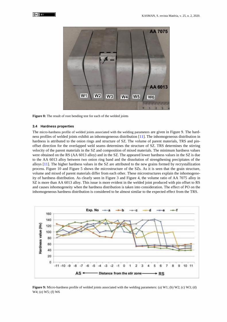
3.4 Hardness properties
The micro-hardness profile of welded joints associated with the welding parameters are given in Figure 9. The hard-
ness profiles of welded joints exhibit an inhomogeneous distribution [11]. The inhomogeneous distribution in
hardness is attributed to the onion rings and structure of SZ. The volume of parent materials, TRS and pin-
offset direction for the overlapped weld seams determines the structure of SZ. TRS determines the stirring
velocity of the parent materials in the SZ and composition of mixed materials. The minimum hardness values
were obtained on the RS (AA 6013 alloy) and in the SZ. The appeared lower hardness values in the SZ is due
to the AA 6013 alloy between two onion ring band and the dissolution of strengthening precipitates of the
alloys [11]. The higher hardness values in the SZ are attributed to the new grains formed by recrystallization
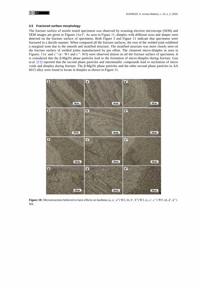
process. Figure 10 and Figure 5 shows the microstructure of the SZs. As it is seen that the grain structure,
volume and mixed of parent materials differ from each other. These microstructures explain the inhomogene-
ity of hardness distribution. As clearly seen in Figure 3 and Figure 4, the volume ratio of AA 7075 alloy in
SZ is more than AA 6013 alloy. This issue is more evident in the welded joint produced with pin offset to RS
and causes inhomogeneity when the hardness distribution is taken into consideration. The effect of PO on the
inhomogeneous hardness distribution is considered to be almost similar to the expected effect from the TRS.
Figure 9: Micro-hardness profile of welded joints associated with the welding parameters: (a) W1; (b) W2; (c) W3; (d)
W4; (e) W5; (f) W6
KASMAN, S. revista Matéria, v. 25, n. 2, 2020.
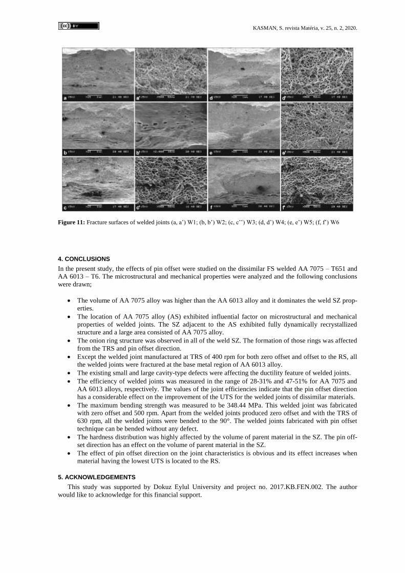
3.5 Fractured surface morphology
The fracture surface of tensile tested specimens was observed by scanning electron microscope (SEM) and
SEM images are given in Figures 11a-f’. As seen in Figure 11, dimples with different sizes and shapes were
detected on the fracture surface of specimens. Both Figure 3 and Figure 11 indicate that specimens were
fractured in a ductile manner. When compared all the fracture surfaces, the root of the welded joint exhibited
a marginal zone due to the smooth and stratified structure. The stratified structure was more clearly seen on
the fracture surface of welded joints manufactured by pin offset. The clustered micro-dimples as seen in
Figures. 11a’ and c’’ (a’: W1 and c’’: W3) were observed almost on all the fracture surface of specimens. It
is considered that the β-Mg2Si phase particles lead to the formation of micro-dimples during fracture. Guo
et.al. [11] reported that the second phase particles and intermetallic compounds lead to nucleation of micro
voids and dimples during fracture. The β-Mg2Si phase particles and the other second phase particles in AA
6013 alloy were found to locate in dimples as shown in Figure 11.
Figure 10: Microstructures believed to have effects on hardness (a, a’, a”) W2; (b, b’, b”) W3; (c, c’, c’’) W5; (d, d’, d’’)
W6
KASMAN, S. revista Matéria, v. 25, n. 2, 2020.
Figure 11: Fracture surfaces of welded joints (a, a’) W1; (b, b’) W2; (c, c’’) W3; (d, d’) W4; (e, e’) W5; (f, f’) W6
4. CONCLUSIONS
In the present study, the effects of pin offset were studied on the dissimilar FS welded AA 7075 – T651 and
AA 6013 – T6. The microstructural and mechanical properties were analyzed and the following conclusions
were drawn;
The volume of AA 7075 alloy was higher than the AA 6013 alloy and it dominates the weld SZ prop-
erties.
The location of AA 7075 alloy (AS) exhibited influential factor on microstructural and mechanical
properties of welded joints. The SZ adjacent to the AS exhibited fully dynamically recrystallized
structure and a large area consisted of AA 7075 alloy.
The onion ring structure was observed in all of the weld SZ. The formation of those rings was affected
from the TRS and pin offset direction.
Except the welded joint manufactured at TRS of 400 rpm for both zero offset and offset to the RS, all
the welded joints were fractured at the base metal region of AA 6013 alloy.
The existing small and large cavity-type defects were affecting the ductility feature of welded joints.
The efficiency of welded joints was measured in the range of 28-31% and 47-51% for AA 7075 and
AA 6013 alloys, respectively. The values of the joint efficiencies indicate that the pin offset direction
has a considerable effect on the improvement of the UTS for the welded joints of dissimilar materials.
The maximum bending strength was measured to be 348.44 MPa. This welded joint was fabricated
with zero offset and 500 rpm. Apart from the welded joints produced zero offset and with the TRS of
630 rpm, all the welded joints were bended to the 90°. The welded joints fabricated with pin offset
technique can be bended without any defect.
The hardness distribution was highly affected by the volume of parent material in the SZ. The pin off-
set direction has an effect on the volume of parent material in the SZ.
The effect of pin offset direction on the joint characteristics is obvious and its effect increases when
material having the lowest UTS is located to the RS.
5. ACKNOWLEDGEMENTS
This study was supported by Dokuz Eylul University and project no. 2017.KB.FEN.002. The author
would like to acknowledge for this financial support.
KASMAN, S. revista Matéria, v. 25, n. 2, 2020.
6. BIBLIOGRAPHY
[1] SHİ, Q.Y., SİLVANUS, J., LİU, Y., et al., “Experimental study on distortion of Al– 6013 plate after
friction stir welding”, Science and Technology of Welding and Joining, v.13, n.5, pp. 472 – 478, 2008.
[2] DERRY, C.G., ROBSON, J.D., “Characterisation and modelling of toughness in 6013– T6 aerospace
aluminium alloy friction stir welds”, Materials Science and Engineering A, v. 490, pp. 328 – 334, 2008.
[3] MİSHRA, R.S., MA Z.Y., “Friction stir welding and processing”, Materials Science and Engineering R,
v. 50, pp: 1 – 78, 2005.
[4] AHMADNİA, M., SHAHRAKİ, S., KAMARPOSHTİ, M.A., “Experimental studies on optimized
mechanical properties while dissimilar joining AA6061 and AA5010 in a friction stir welding process”, The
International Journal of Advanced Manufacturing Technology, v.87, pp: 2337 – 2352, 2016.
[5] ALİHA, M.R.M., SHAHHEİDARİ, M., BİSADİ, M., et al., Mechanical and metallurgical properties of
dissimilar AA6061– T6 and AA7277– T6 joint made by FSW technique, The International Journal of
Advanced Manufacturing Technology, v.86, pp: 2551 – 2565, 2016.
[6] COLE, E.G., FEHRENBACHER, A., DUFFİE, N.A., et al., Weld temperature effects during friction stir
welding of dissimilar aluminum alloys 6061-T6 and 7075-T6, The International Journal of Advanced
Manufacturing Technology, v.71, pp: 643 – 652, 2014.
[7] DANİOLOS, N.M., PANTELİS, D.I., “Microstructural and mechanical properties of dissimilar friction
stir welds between AA6082– T6 and AA7075– T651”, The International Journal of Advanced Manufacturing
Technology, v.88, pp: 2497 – 2505, 2017.
[8] AVAL, H.J., “Influences of pin profile on the mechanical and microstructural behaviors in dissimilar
friction stir welded AA6082 – AA7075 butt Joint”, Materials and Design, v.67, pp: 413 – 421, 2015.
[9] PATİL, H.S., SHARMA, N., PATEL, K., “Effect of Processing Parameters on Properties of Friction Stir
Welded Joints of Aluminium Alloys AA7075 – T651 and AA6061 – T6”, The International Journal of
Advanced Manufacturing Technology, v.10, n. 2, pp. 93 – 99, 2017.
[10] RAVİKUMAR, S., SESHAGİRİ, V., PRANESH, R.V., “Effect of Welding Parameters on Macro and
Microstructure of Friction Stir Welded Dissimilar Butt Joints between AA7075 – T651 and AA6061 – T651
Alloys”, Procedia Materials Science, v.5, pp: 1726 – 1735, 2014.
[11] GUO, J.F., CHEN, H.C., SUN, C.N., et al., “Friction stir welding of dissimilar materials between
AA6061 and AA7075 Al alloys effects of process parameters”, Materials and Design, v.56, pp: 185 – 192,
2014.
[12] HASAN, M.M., ISHAK, M., REJAB, M.R.M., “Influence of machine variables and tool profile on the
tensile strength of dissimilar AA7075 – AA6061 friction stir welds”, The International Journal of Advanced
Manufacturing Technology, v.90, pp: 2605 – 2615, 2017.
[13] GİRAUD, L., ROBE, H., CLAUDİN, C., et al., “Investigation into the dissimilar friction stir welding of
AA7020 – T651 and AA6060 – T6”, Journal of Materials Processing Technology, v.235, pp: 220 – 230,
2016.
[14] RAJAKUMAR, S., BALASUBRAMANİAN, V., “Establishing relationships between mechanical
properties of aluminum alloys and optimized friction stir welding process parameters”, Materials and Design,
v. 40, pp: 17 – 35, 2012.
[15] RENGARAJAN, S., RAO,V.S., “Characteristics of AA7075 – T6 and AA6061 – T6 Friction Welded
Joints”, Transactions of the Canadian Society for Mechanical Engineering, v. 39, n. 4, pp. 845 – 854, 2015.
[16] SARAVANAN, V., RAJAKUMAR, S., MURUGANANDAM, A., “Effect of Friction Stir Welding
Process Parameters on Microstructure and Mechanical Properties of Dissimilar AA6061 – T6 and AA7075 –
T6 Aluminum Alloy Joints”, Metallogr Microstruct Anal., v.5, pp. 476 – 485, 2016.
[17] SATHARİ, N.A.A., RAZALİ, A.R., ISHAK, M., et al., “Mechanical Strength of Dissimilar AA7075
and AA6061 Aluminum Alloys Using Friction Stir Welding”, International Journal of Automotive and
Mechanical Engineering (IJAME), v.11, pp: 2713 – 2721, 2015.
[18] TENAGLİA, R., Dissimilar Materials Joining, http://ewi.org. (2012), pp: 1 – 4.
[19] MARTİNSEN, K., HU, S.J., CARLSON, B.E., “Joining of Dissimilar Materials”, CIRP Annals –
Manufacturing Technology, v. 64, pp. 679 – 699, 2015.
[20] AHMED, M.M.Z., ATAYA, S., SELEMAN, M.M.S., et al., “Friction stir welding of similar and
dissimilar AA7075 and AA5083”, Journal of Materials Processing Technology, v. 242, pp. 77 – 91, 2017.
KASMAN, S. revista Matéria, v. 25, n. 2, 2020.
[21] LAKSHMİNARAYANAN, A.K., BALASUBRAMANİAN, V., “An assessment of microstructure,
hardness, tensile and impact strength of friction stir welded ferritic stainless steel joints”, Materials and
Design, v. 31, pp. 4592 – 4600, 2010.
[22] SHARMA, C., DWİVEDİ, D.K., KUMAR, P., “Effect of welding parameters on microstructure and
mechanical properties of friction stir welded joints of AA7039 aluminum alloy”, Materials and Design, v.36,
pp: 379 – 390, 2012.
[23] SHARMA, C., DWİVEDİ, D.K., KUMAR, P., “Influence of pre-weld temper conditions of base metal
on microstructure and mechanical properties of friction stir weld joints of Al–Zn–Mg alloy AA7039”,
Materials Science & Engineering A, v. 620, pp: 107 – 119, 2015.
[24] MAO, Y., LİMİNG, K., LİU, F., et al., “Effect of tool pin eccentricity on microstructure and mechanical
properties in friction stir welded 7075 aluminum alloy thick plate”, The International Journal of Advanced
Manufacturing Technology, v. 62, pp: 334 – 343, 2014.
[25] MAO, Y., LİMİNG, K., CHEN, Y., et al., “Investigations on temperature distribution, microstructure
evolution, and property variations along thickness in friction stir welded joints for thick AA7075 – T6
plates”, The International Journal of Advanced Manufacturing Technology, v. 86, pp. 141 – 154, 2016.
[26] MAO, Y., LİMİNG, K., CHUNPİNG, H., et al., “Formation characteristic, microstructure, and
mechanical performances of aluminum-based components by friction stir additive manufacturing”, The
International Journal of Advanced Manufacturing Technology, v. 83, pp. 1637 – 1647, 2016.
[27] FU, R., XU, H., LUAN, G., et al., “Top surface microstructure of friction-stir welded AA2524 – T3
aluminum alloy joints”, Materials Characterization, v. 65, pp: 48 – 54, 2012.
[28] DEHGHANİ, K., GHORBANİ, R., SOLTANİPOOR, A.R., “Microstructural evolution and mechanical
properties during the friction stir welding of 7075 – O aluminum alloy”, The International Journal of
Advanced Manufacturing Technology, v. 77, pp: 1671 – 1679, 2015.
[29] BİROL, Y., KASMAN, Ş., “Effect of Welding Parameters on the Microstructure and Stength of Friction
Stir Weld Joints in Twin Roll Cast EN AW Al-Mn1Cu Plates”, Journal of Materials Engineering and
Performance, v. 22, n.10, pp. 3024 – 3033, 2013.
[30] YUN, X., MA, H., XİONG, L., et al., “Effect of lateral offset on microstructure and strength of friction
stir welded 2A14-T6 aluminum alloy”, The International Journal of Advanced Manufacturing Technology, v.
97, p: 3893 – 3902, 2018.
ORCID
Sefika Kasman https://orcid.org/0000-0002-4722-9203
![Non-destructive Evaluation of Friction Stir Welded Joints ... · strength of the FSW joint for AC4C Al alloy and Steel dissimilar friction stir lap joints [7]. Aluminum alloy welds](https://static.cupdf.com/doc/110x72/5e5c511832f9297d8a597cf4/non-destructive-evaluation-of-friction-stir-welded-joints-strength-of-the-fsw.jpg)


![Solid State Friction Stir Welding (FSW) on Similar and ... · PDF fileGang and Feng [5] proposed simple ... Solid State Friction Stir Welding (FSW) on Similar and Dissimilar Metals](https://static.cupdf.com/doc/110x72/5aa3e49c7f8b9a07758ed7bd/solid-state-friction-stir-welding-fsw-on-similar-and-and-feng-5-proposed.jpg)