Superscalar Processors:Branch Prediction
Dynamic Scheduling
Superscalar Processors
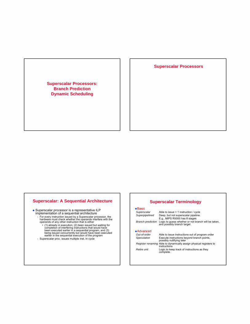
Superscalar: A Sequential Architecture
Superscalar processor is a representative ILP implementation of a sequential architecture
- For every instruction issued by a Superscalar processor, the hardware must check whether the operands interfere with the operands of any other instruction that is either
• (1) already in execution, (2) been issued but waiting for completion of interfering instructions that would have been executed earlier in a sequential program, and (3) being issued concurrently but would have been executed earlier in the sequential execution of the program
- Superscalar proc. issues multiple inst. In cycle
Superscalar TerminologyBasic
Superscalar Able to issue > 1 instruction / cycleSuperpipelined Deep, but not superscalar pipeline.
E.g., MIPS R5000 has 8 stagesBranch prediction Logic to guess whether or not branch will be taken,
and possibly branch target
AdvancedOut-of-order Able to issue instructions out of program orderSpeculation Execute instructions beyond branch points,
possibly nullifying laterRegister renaming Able to dynamically assign physical registers to
instructionsRetire unit Logic to keep track of instructions as they
complete.
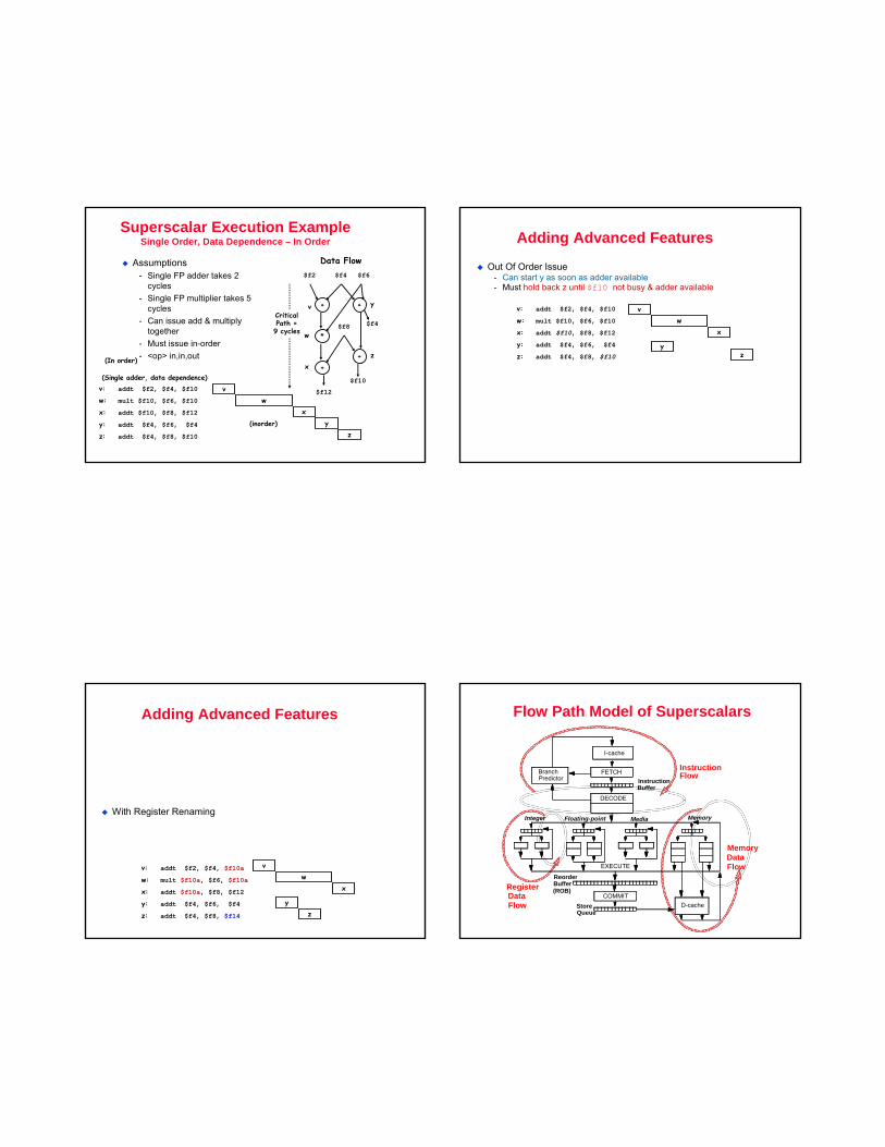
Superscalar Execution ExampleSingle Order, Data Dependence – In Order
Assumptions- Single FP adder takes 2
cycles- Single FP multiplier takes 5
cycles- Can issue add & multiply
together- Must issue in-order- <op> in,in,out
v: addt $f2, $f4, $f10
w: mult $f10, $f6, $f10
x: addt $f10, $f8, $f12
y: addt $f4, $f6, $f4
z: addt $f4, $f8, $f10
vw
xy
(Single adder, data dependence)
(In order)
(inorder)
Data Flow
+ +
*
+
$f2 $f4 $f6
$f4
$f10
$f8
yv
xz
CriticalPath =9 cycles
+
w
z
$f12
z
Adding Advanced Features
Out Of Order Issue- Can start y as soon as adder available- Must hold back z until $f10 not busy & adder available
vw
x
yz
v: addt $f2, $f4, $f10
w: mult $f10, $f6, $f10
x: addt $f10, $f8, $f12
y: addt $f4, $f6, $f4
z: addt $f4, $f8, $f10
Adding Advanced Features
With Register Renaming
vw
x
yz
v: addt $f2, $f4, $f10a
w: mult $f10a, $f6, $f10a
x: addt $f10a, $f8, $f12
y: addt $f4, $f6, $f4
z: addt $f4, $f8, $f14
Flow Path Model of Superscalars
I-cache
FETCH
DECODE
COMMITD-cache
BranchPredictor Instruction
Buffer
StoreQueue
ReorderBuffer
Integer Floating-point Media Memory
Instruction
RegisterData
MemoryData
Flow
EXECUTE
(ROB)
Flow
Flow
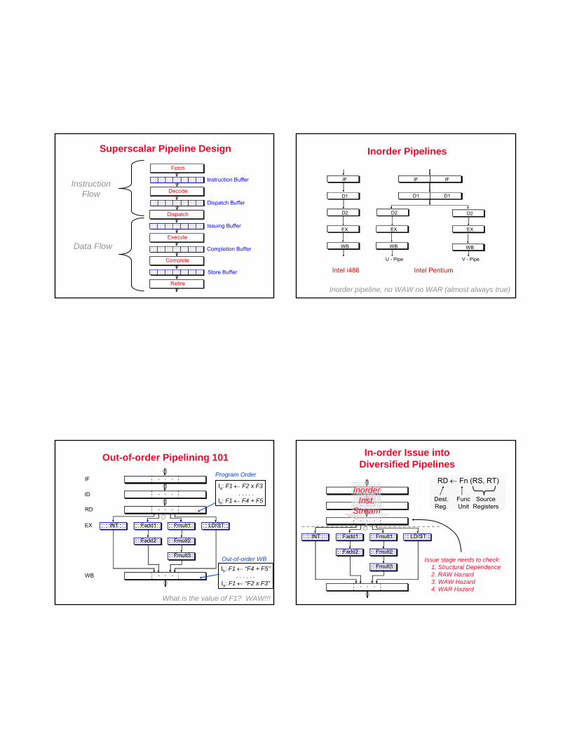
Superscalar Pipeline Design
Instruction Buffer
Fetch
Dispatch Buffer
Decode
Issuing Buffer
Dispatch
Completion Buffer
Execute
Store Buffer
Complete
Retire
InstructionFlow
Data Flow
Inorder Pipelines
IF
D1
D2
EX
WB
Intel i486
IF IF
D1 D1
D2 D2
EX EX
WB WB
Intel Pentium
U - Pipe V - Pipe
Inorder pipeline, no WAW no WAR (almost always true)
Out-of-order Pipelining 101
• • •
• • •
• • •
• • •IF
ID
RD
WB
INT Fadd1 Fmult1 LD/ST
Fadd2 Fmult2
Fmult3
EX
Program Order
Ia: F1 ← F2 x F3. . . . .
Ib: F1 ← F4 + F5
What is the value of F1? WAW!!!
Out-of-order WBIb: F1 ← “F4 + F5”
. . . . . .Ia: F1 ← “F2 x F3”
In-order Issue into Diversified Pipelines
• • •
• • •
• • •
• • •
INT Fadd1 Fmult1 LD/ST
Fadd2 Fmult2
Fmult3
RD ← Fn (RS, RT)
Dest.Reg.
FuncUnit
SourceRegisters
Issue stage needs to check:1. Structural Dependence2. RAW Hazard3. WAW Hazard4. WAR Hazard
InorderInst.
Stream
Icache
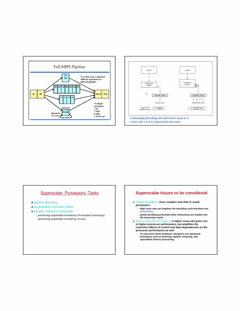
Superscalar issue
DF . . .I
Decode / IssueDecode / Issue
Scalar issue
Typical FX-pipeline layout D/IF . . .
Icache
Instructionbuffer
Instructionbuffer
Contrasting decoding and instruction issue in a scalar and a 4-way superscalar processor
Superscalar Processors: Tasks
parallel decodingsuperscalar instruction issueparallel instruction execution
- preserving sequential consistency of exception processing- preserving sequential consistency of exec.
Superscalar Issues to be considered
Parallel decoding – more complex task than in scalar processors.
- High issue rate can lengthen the decoding cycle therefore use predecoding.
- partial decoding performed while instructions are loaded into the instruction cache
Superscalar instruction issue – A higher issue rate gives rise to higher processor performance, but amplifies the restrictive effects of control and data dependencies on the processor performance as well.
- To overcome these problems designers use advanced techniques such as shelving, register renaming, and speculative branch processing
Superscalar issues
Parallel instruction execution task – Also called “preservation of the sequential consistency of instruction execution”. While instructions are executed in parallel, instructions are usually completed out of order in respect to a sequential operating procedurePreservation of sequential consistency of exception processing task
Pre-Decoding
more EUs than the scalar processors, therefore higher number of instructions in execution
- more dependency check comparisons needed
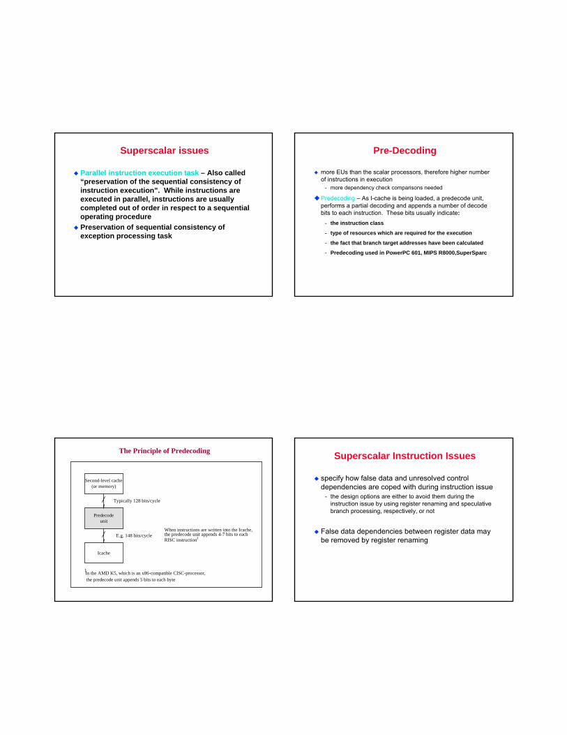
Predecoding – As I-cache is being loaded, a predecode unit, performs a partial decoding and appends a number of decode bits to each instruction. These bits usually indicate:
- the instruction class
- type of resources which are required for the execution
- the fact that branch target addresses have been calculated
- Predecoding used in PowerPC 601, MIPS R8000,SuperSparc
Second-level cache(or memory)
Predecodeunit
Icache
Typically 128 bits/cycle
When instructions are written into the Icache,the predecode unit appends 4-7 bits to eachRISC instruction
E.g. 148 bits/cycle 1
In the AMD K5, which is an x86-compatible CISC-processor,the predecode unit appends 5 bits to each byte
1
The Principle of Predecoding Superscalar Instruction Issues
specify how false data and unresolved control dependencies are coped with during instruction issue
- the design options are either to avoid them during the instruction issue by using register renaming and speculative branch processing, respectively, or not
False data dependencies between register data may be removed by register renaming
Instruction Issue Unit- Care must be taken not to issue an instruction if another
instruction upon which it is dependent is not complete- Requires complex control logic in Superscalar processors- Virtually trivial control logic in VLIW processors
Hardware Features to Support ILP Parallel Execution
when instructions executed in parallel they will finish out of program order
- unequal execution times
specific means needed to preserve logical consistency- preservation of sequential consistency
exceptions during execution- preservation seq. consistency exception proc.
Speculative Execution- Little ILP typically found in basic blocks
• a straight-line sequence of operations with no intervening control flow
- Multiple basic blocks must be executed in parallel• Execution may continue along multiple paths before it is
known which path will be executed
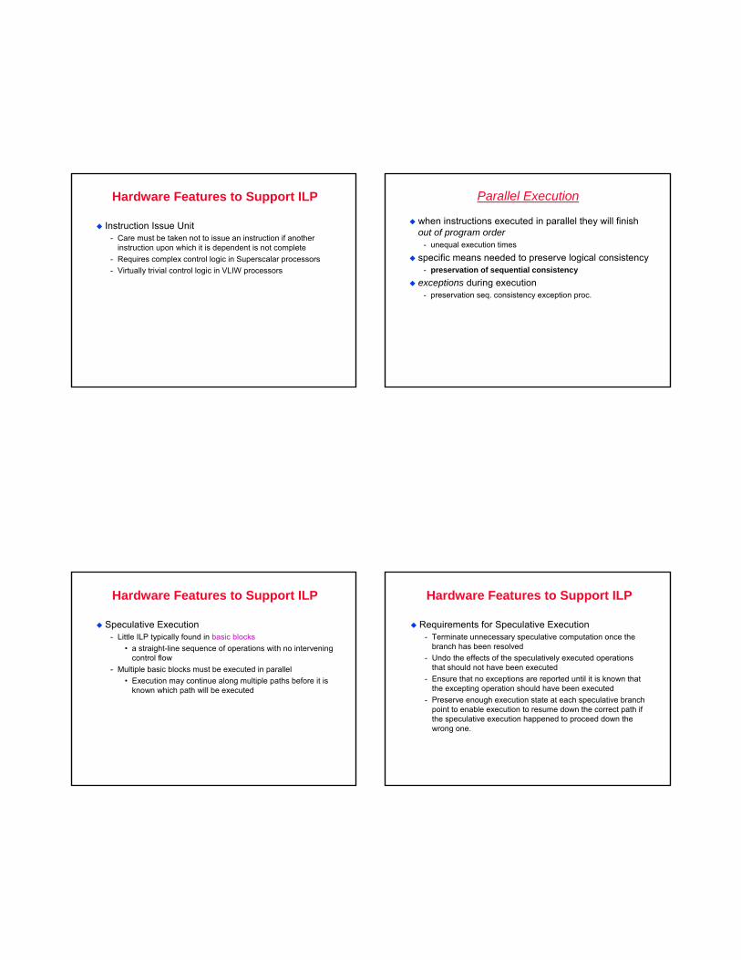
Hardware Features to Support ILP
Requirements for Speculative Execution- Terminate unnecessary speculative computation once the
branch has been resolved- Undo the effects of the speculatively executed operations
that should not have been executed- Ensure that no exceptions are reported until it is known that
the excepting operation should have been executed- Preserve enough execution state at each speculative branch
point to enable execution to resume down the correct path if the speculative execution happened to proceed down the wrong one.
Hardware Features to Support ILP
Speculative Execution- Expensive in hardware- Alternative is to perform speculative code motion at compile
time• Move operations from subsequent blocks up past branch
operations into proceeding blocks- Requires less demanding hardware
• A mechanism to ensure that exceptions caused by speculatively scheduled operations are reported if and only if flow of control is such that they would have been executed in the non-speculative version of the code
• Additional registers to hold the speculative execution state
Hardware Features to Support ILP Next. . . Superscalar Processor Design
How to deal with instruction flow- Dynamic Branch prediction
How to deal with register/data flow- Register renaming
Solutions studied:- Dynamic branch prediction algorithms- Dynamic scheduling using Tomasulo method
Summary of discussions
ILP processors- VLIW/EPIC, Superscalar
Superscalar has hardware logic for extracting parallelism- Solutions for stalls etc. must be provided in hardware
Stalls play an even greater role in ILP processorsSoftware solutions, such as code scheduling through code movement, can lead to improved execution times- More sophisticated techniques needed- Can we provide some H/W support to help the compiler –
leads to EPIC/VLIW
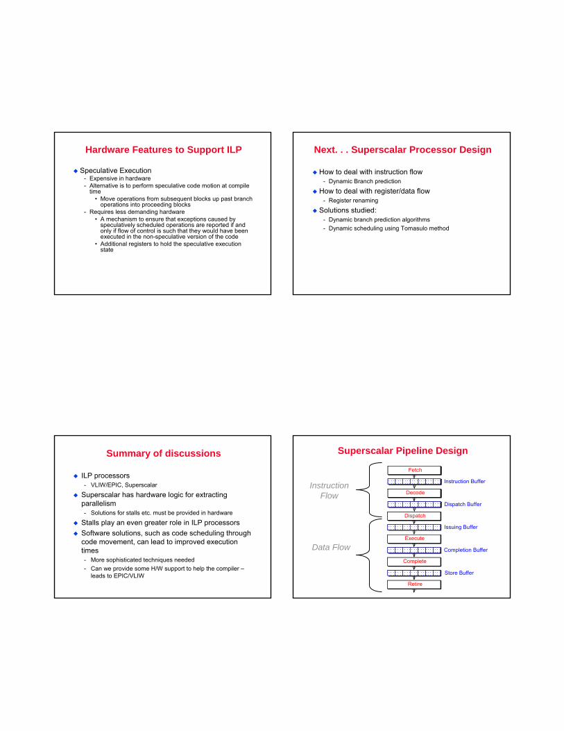
Superscalar Pipeline Design
Instruction Buffer
Fetch
Dispatch Buffer
Decode
Issuing Buffer
Dispatch
Completion Buffer
Execute
Store Buffer
Complete
Retire
InstructionFlow
Data Flow
Flow Path Model of Superscalars
I-cache
FETCH
DECODE
COMMITD-cache
BranchPredictor Instruction
Buffer
StoreQueue
ReorderBuffer
Integer Floating-point Media Memory
Instruction
RegisterData
MemoryData
Flow
EXECUTE
(ROB)
Flow
Flow
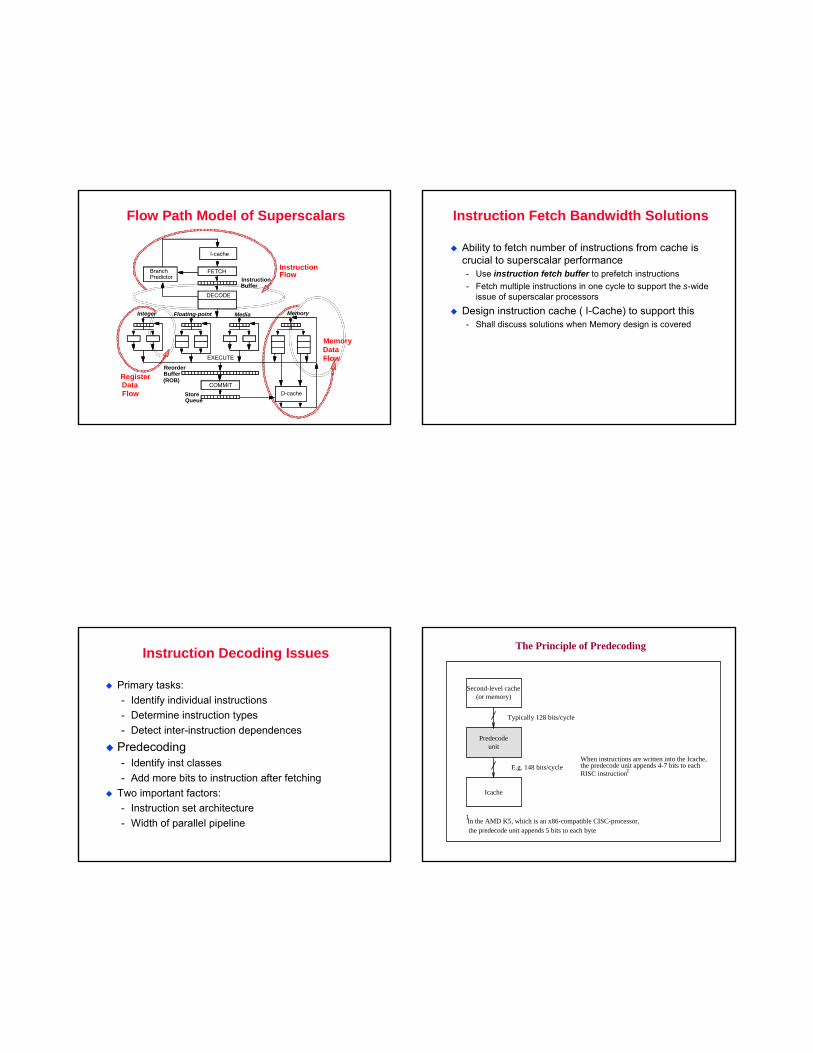
Instruction Fetch Bandwidth Solutions
Ability to fetch number of instructions from cache is crucial to superscalar performance- Use instruction fetch buffer to prefetch instructions- Fetch multiple instructions in one cycle to support the s-wide
issue of superscalar processors
Design instruction cache ( I-Cache) to support this- Shall discuss solutions when Memory design is covered
Instruction Decoding Issues
Primary tasks:- Identify individual instructions- Determine instruction types- Detect inter-instruction dependences
Predecoding- Identify inst classes- Add more bits to instruction after fetching
Two important factors:- Instruction set architecture- Width of parallel pipeline
Second-level cache(or memory)
Predecodeunit
Icache
Typically 128 bits/cycle
When instructions are written into the Icache,the predecode unit appends 4-7 bits to eachRISC instruction
E.g. 148 bits/cycle 1
In the AMD K5, which is an x86-compatible CISC-processor,the predecode unit appends 5 bits to each byte
1
The Principle of Predecoding
Control Dependence andBranch Prediction
Instruction Flow– Control Flow
Throughput of early stages places bound an upper bound on per. Of subsequent stagesProgram control flow represented by Control Flow Graph (CFG)- Nodes represent basic block of code
• Sequence of instructions with no incoming or outgoing branches
- Edges represent transfer of control flow from one block to another
IBM’s Experience on Pipelined Processors [Agerwala and Cocke 1987]
Code Characteristics (dynamic)- loads - 25%- stores - 15%- ALU/RR - 40%- branches - 20%
• 1/3 unconditional (always taken)unconditional - 100% schedulable
• 1/3 conditional taken• 1/3 conditional not taken
conditional - 50% schedulable
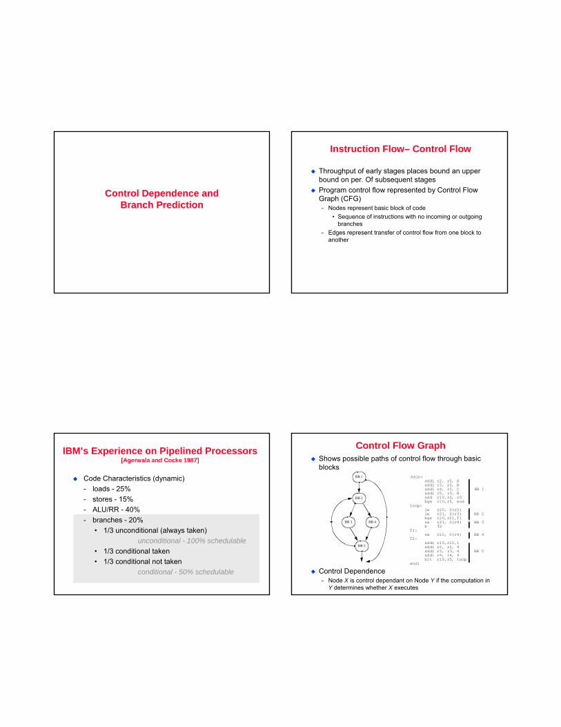
Control Flow GraphShows possible paths of control flow through basic blocks
Control Dependence- Node X is control dependant on Node Y if the computation in
Y determines whether X executes
BB 1
BB 2
BB 3 BB 4
BB 5
main: addi r2, r0, A addi r3, r0, B addi r4, r0, C BB 1 addi r5, r0, N add r10,r0, r0 bge r10,r5, end loop: lw r20, 0(r2) lw r21, 0(r3) BB 2 bge r20,r21,T1 sw r21, 0(r4) BB 3 b T2 T1: sw r20, 0(r4) BB 4 T2: addi r10,r10,1 addi r2, r2, 4 addi r3, r3, 4 BB 5 addi r4, r4, 4 blt r10,r5, loop end:
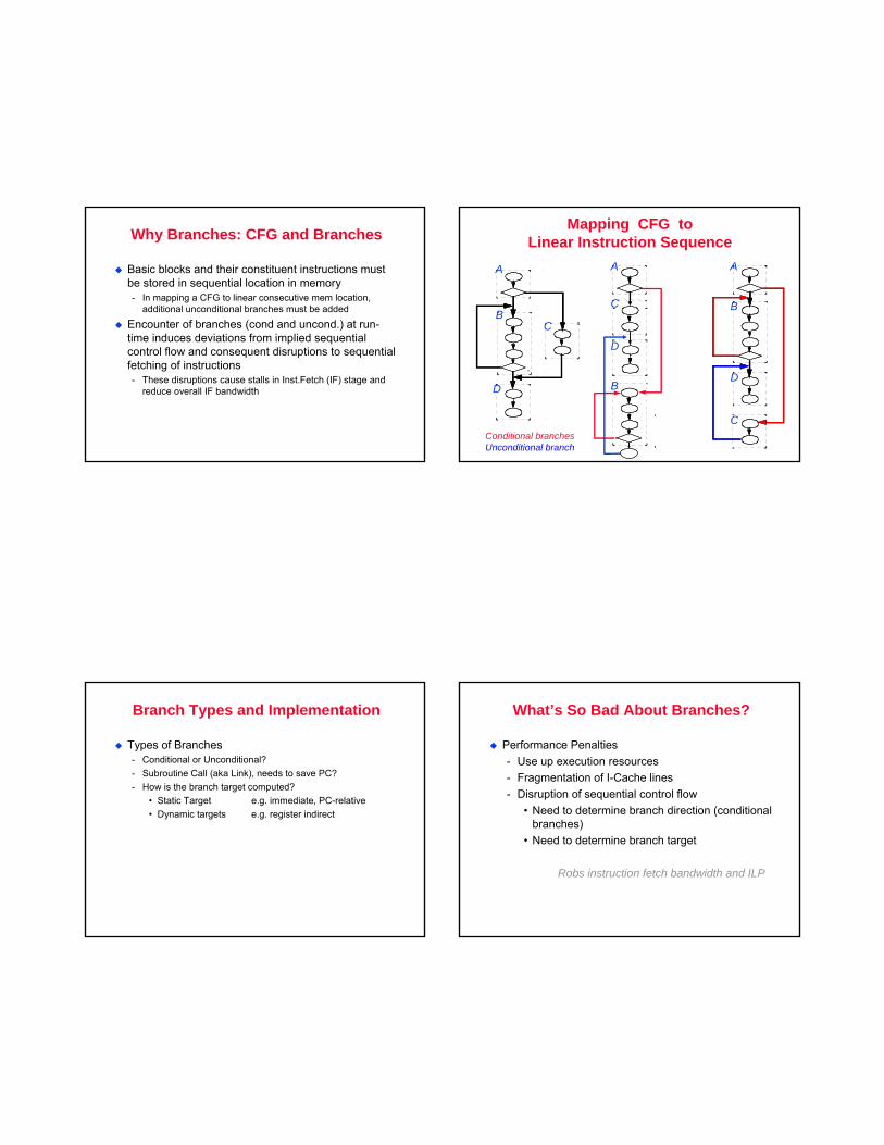
Why Branches: CFG and Branches
Basic blocks and their constituent instructions must be stored in sequential location in memory- In mapping a CFG to linear consecutive mem location,
additional unconditional branches must be added
Encounter of branches (cond and uncond.) at run-time induces deviations from implied sequential control flow and consequent disruptions to sequential fetching of instructions- These disruptions cause stalls in Inst.Fetch (IF) stage and
reduce overall IF bandwidth
Mapping CFG toLinear Instruction Sequence
A A
B
B
A
BC
DD
C
C
D
Conditional branchesUnconditional branch
Branch Types and Implementation
Types of Branches- Conditional or Unconditional?- Subroutine Call (aka Link), needs to save PC?- How is the branch target computed?
• Static Target e.g. immediate, PC-relative• Dynamic targets e.g. register indirect
What’s So Bad About Branches?
Performance Penalties- Use up execution resources- Fragmentation of I-Cache lines- Disruption of sequential control flow
• Need to determine branch direction (conditional branches)
• Need to determine branch target
Robs instruction fetch bandwidth and ILP
Branch-- actions
When branches occur, disruption to IF occursFor unconditional branches- Subsequent instruction cannot be fetched until target
address determined
For conditional branches- Machine must wait for resolution of branch condition - And if branch taken then wait till target address computed
Branch inst executed by the branch functional unitNote: Cost in superscalar/ILP processors = width (parallelism) X stall cycles- 3 stall cycles on a 4 wide machine = 12 lost cycles
CPU Performance..
Recall: CPU time = IC*CPI*Clk- CPI = ideal CPI + stall cycles/inst- Minimizing CPI implies minimize stall cycles- Stall cycles from branch instructions
• How to determine the number of stall cycles
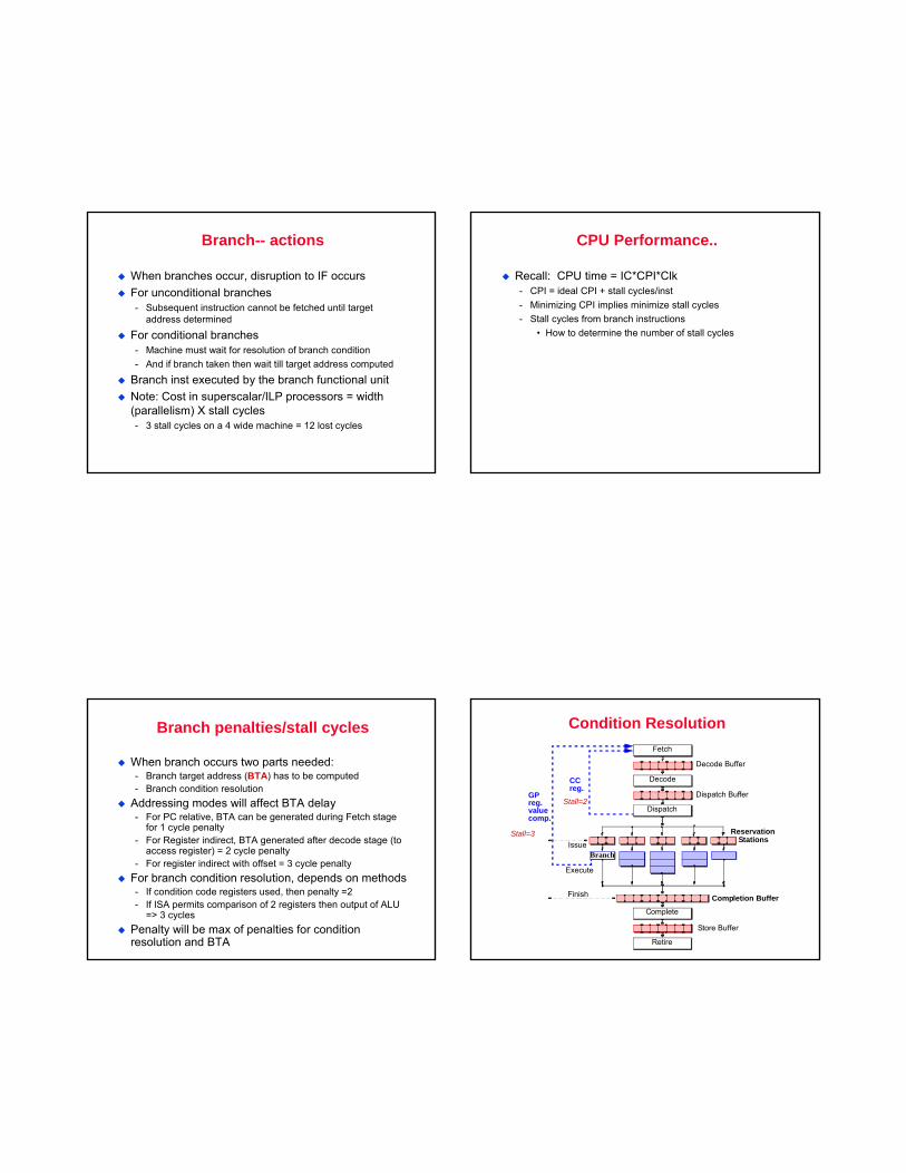
Branch penalties/stall cycles
When branch occurs two parts needed:- Branch target address (BTA) has to be computed- Branch condition resolution
Addressing modes will affect BTA delay- For PC relative, BTA can be generated during Fetch stage
for 1 cycle penalty- For Register indirect, BTA generated after decode stage (to
access register) = 2 cycle penalty- For register indirect with offset = 3 cycle penalty
For branch condition resolution, depends on methods- If condition code registers used, then penalty =2- If ISA permits comparison of 2 registers then output of ALU
=> 3 cyclesPenalty will be max of penalties for condition resolution and BTA
Condition Resolution
Decode Buffer
Fetch
Dispatch Buffer
Decode
Reservation
Dispatch
Store Buffer
Complete
Retire
StationsIssue
Execute
Finish Completion Buffer
Branch
CCreg.
GPreg.valuecomp.
Stall=3
Stall=2
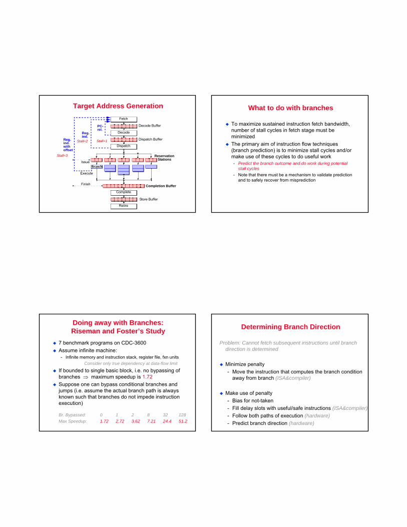
Target Address Generation
Decode Buffer
Fetch
Dispatch Buffer
Decode
Reservation
Dispatch
Store Buffer
Complete
Retire
StationsIssue
Execute
Finish Completion Buffer
Branch
PC-rel.
Reg.ind.
Reg.ind.withoffset
Stall=1Stall=2
Stall=3
What to do with branches
To maximize sustained instruction fetch bandwidth, number of stall cycles in fetch stage must be minimizedThe primary aim of instruction flow techniques (branch prediction) is to minimize stall cycles and/or make use of these cycles to do useful work- Predict the branch outcome and do work during potential
stall cycles- Note that there must be a mechanism to validate prediction
and to safely recover from misprediction
Doing away with Branches:Riseman and Foster’s Study
7 benchmark programs on CDC-3600Assume infinite machine:- Infinite memory and instruction stack, register file, fxn units
Consider only true dependency at data-flow limit
If bounded to single basic block, i.e. no bypassing of branches ⇒ maximum speedup is 1.72Suppose one can bypass conditional branches and jumps (i.e. assume the actual branch path is always known such that branches do not impede instruction execution)
Br. Bypassed: 0 1 2 8 32 128Max Speedup: 1.72 2.72 3.62 7.21 24.4 51.2
Determining Branch Direction
Problem: Cannot fetch subsequent instructions until branch direction is determined
Minimize penalty- Move the instruction that computes the branch condition
away from branch (ISA&compiler)
Make use of penalty- Bias for not-taken- Fill delay slots with useful/safe instructions (ISA&compiler)- Follow both paths of execution (hardware)- Predict branch direction (hardware)
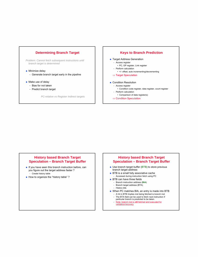
Determining Branch Target
Problem: Cannot fetch subsequent instructions until branch target is determined
Minimize delay- Generate branch target early in the pipeline
Make use of delay- Bias for not taken- Predict branch target
PC-relative vs Register Indirect targets
Keys to Branch Prediction
Target Address Generation- Access register
• PC, GP register, Link register- Perform calculation
• +/- offset, auto incrementing/decrementing
⇒ Target Speculation
Condition Resolution- Access register
• Condition code register, data register, count register- Perform calculation
• Comparison of data register(s)
⇒ Condition Speculation
History based Branch Target Speculation – Branch Target BufferIf you have seen this branch instruction before, can you figure out the target address faster ?- Create history table
How to organize the “history table” ?
History based Branch Target Speculation – Branch Target BufferUse branch target buffer (BTB) to store previous branch target addressBTB is a small fully associative cache- Accessed during instruction fetch using PC
BTB can have three fields- Branch instruction address (BIA)- Branch target address (BTA)- History bits
When PC matches BIA, an entry is made into BTB- A hit in BTB Implies inst being fetched is branch inst- The BTA field can be used to fetch next instruction if
particular branch is predicted to be taken - Note: branch inst is still fetched and executed for
validation/recovery
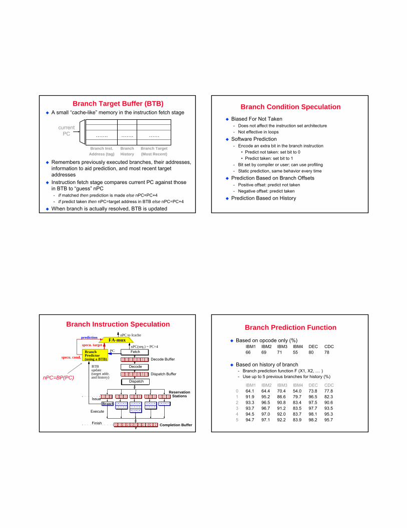
A small “cache-like” memory in the instruction fetch stage
Remembers previously executed branches, their addresses, information to aid prediction, and most recent target addressesInstruction fetch stage compares current PC against those in BTB to “guess” nPC- If matched then prediction is made else nPC=PC+4- If predict taken then nPC=target address in BTB else nPC=PC+4
When branch is actually resolved, BTB is updated
Branch Target(Most Recent)
Branch History
Branch Inst.Address (tag)
………….…….
Branch Target Buffer (BTB)
currentPC
Branch Condition SpeculationBiased For Not Taken- Does not affect the instruction set architecture- Not effective in loops
Software Prediction- Encode an extra bit in the branch instruction
• Predict not taken: set bit to 0• Predict taken: set bit to 1
- Bit set by compiler or user; can use profiling- Static prediction, same behavior every time
Prediction Based on Branch Offsets- Positive offset: predict not taken- Negative offset: predict taken
Prediction Based on History
Branch Instruction Speculation
Decode Buffer
Fetch
Dispatch Buffer
Decode
Reservation
Dispatch
StationsIssue
Execute
Finish Completion Buffer
Branch
nPC to Icache
nPC(seq.) = PC+4PCBranch
Predictor(using a BTB)
specu. target
BTBupdate
prediction
(target addr.and history)
specu. cond.
FA-mux
nPC=BP(PC)
Branch Prediction Function
Based on opcode only (%)IBM1 IBM2 IBM3 IBM4 DEC CDC66 69 71 55 80 78
Based on history of branch- Branch prediction function F (X1, X2, .... )- Use up to 5 previous branches for history (%)
IBM1 IBM2 IBM3 IBM4 DEC CDC0 64.1 64.4 70.4 54.0 73.8 77.81 91.9 95.2 86.6 79.7 96.5 82.32 93.3 96.5 90.8 83.4 97.5 90.63 93.7 96.7 91.2 83.5 97.7 93.54 94.5 97.0 92.0 83.7 98.1 95.35 94.7 97.1 92.2 83.9 98.2 95.7
History based prediction
Make prediction based on previous observation- historical info on direction taken by branch in previous
execution can hints on direction taken in future
How much history ? What prediction ?- History means how many branches and for each branch how
much ?
Where to store the history ?
Finite State Machine based predictors
FSMs- capture history- Easy and fast to design and implement- Transition from one state to another on input
FSM branch prediction algorithm- N state variables encode direction taken by last n exec of
branch• Each state represents particular history pattern in terms
of taken/not-taken (T/NT)• Output logic generates prediction based on history
- When predicted branch is finally executed, use actual outcome to transition to next state
- Next state logic – chain state variables into shift Reg.
N-bit predictors
Store outcome of last N occurences of branche- 1-bit predictor implies store history of last branch only
The values of the N bits is the “state” of the branch predictorUse history of last N to predict next- Use the value of the N-bit ‘state’ to predict the branch – this
is the prediction algorithm- Implement the ‘algorithm’ using some logic gates- How much time does algorithm have to compute outcome ??
Larger the size of N, the more hardware you need to implement the N bit predictorHow many branch instructions ?- Size of/entries in the Branch history table, BTB – 1024,
2048,etc.
2-bit predictors
Use 2 history bits to track outcome of 2 previous executions of branch- 2 bits are status of FSM- NN, NT, TN, TT
Each FSM represents a prediction algorithmTo support history based prediction, the BTB includes history field for each branch- Retrieve target address plus history bits- Feed history bits to logic that generates next state and
prediction
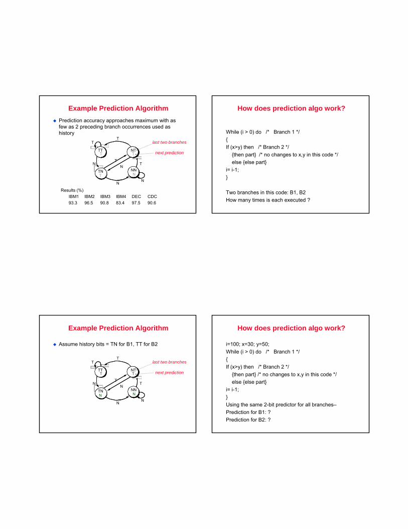
Prediction accuracy approaches maximum with as few as 2 preceding branch occurrences used as history
Results (%)IBM1 IBM2 IBM3 IBM4 DEC CDC93.3 96.5 90.8 83.4 97.5 90.6
Example Prediction Algorithm
TTT
N
T
NTT
TNTTNT
NNN
N
T
T
N
TN
TTT
last two branches
next prediction
How does prediction algo work?
While (i > 0) do /* Branch 1 */{If (x>y) then /* Branch 2 */
{then part} /* no changes to x,y in this code */else {else part}
i= i-1;}
Two branches in this code: B1, B2How many times is each executed ?
Example Prediction Algorithm
TTT
N
T
NTT
TNTTNN
NNN
N
T
T
N
TN
TTT
last two branches
next prediction
Assume history bits = TN for B1, TT for B2
How does prediction algo work?
i=100; x=30; y=50;While (i > 0) do /* Branch 1 */{If (x>y) then /* Branch 2 */
{then part} /* no changes to x,y in this code */else {else part}
i= i-1;}Using the same 2-bit predictor for all branches–Prediction for B1: ?Prediction for B2: ?
N
TN
N
T
TNTn?
T
tT
N
N
T
TNT
t?
T
T N
n?
tt?
NN
nn
T N
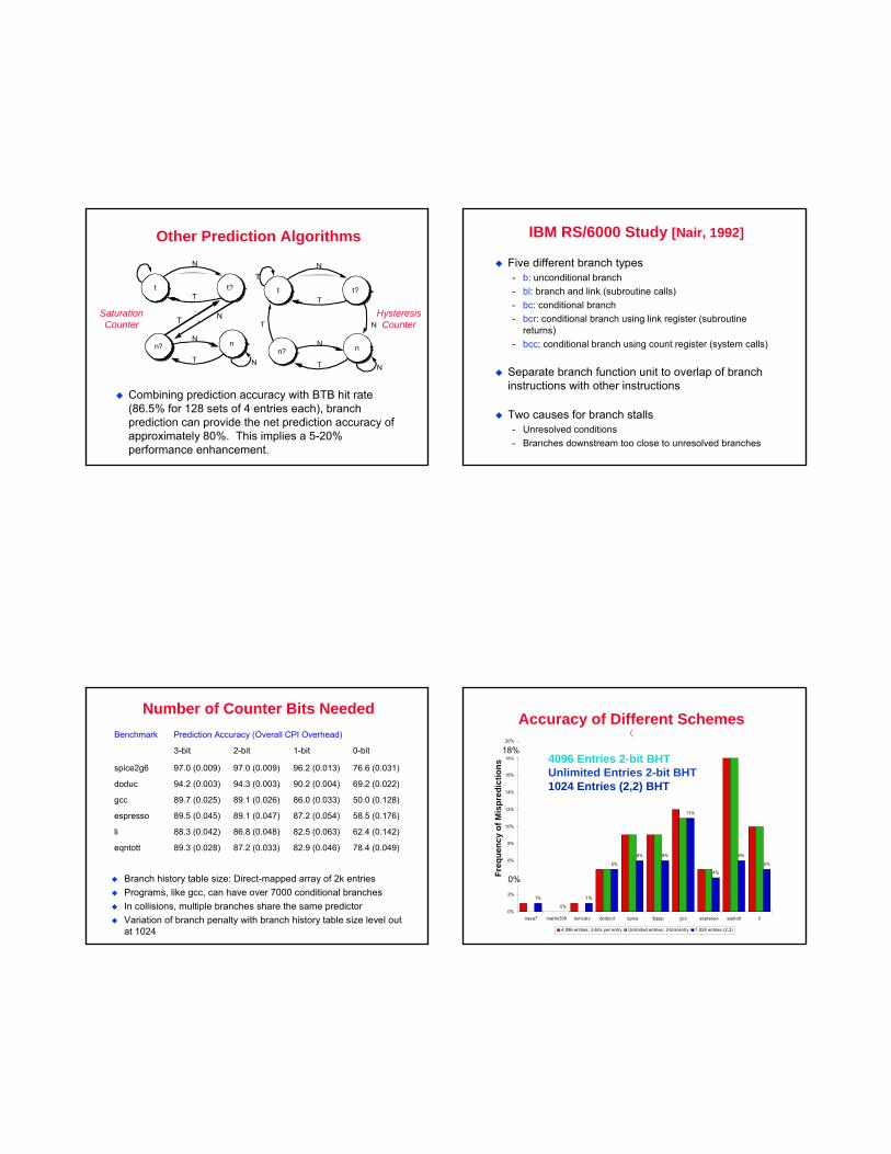
Other Prediction Algorithms
Combining prediction accuracy with BTB hit rate (86.5% for 128 sets of 4 entries each), branch prediction can provide the net prediction accuracy of approximately 80%. This implies a 5-20% performance enhancement.
SaturationCounter
HysteresisCounter
IBM RS/6000 Study [Nair, 1992]
Five different branch types- b: unconditional branch- bl: branch and link (subroutine calls)- bc: conditional branch- bcr: conditional branch using link register (subroutine
returns)- bcc: conditional branch using count register (system calls)
Separate branch function unit to overlap of branch instructions with other instructions
Two causes for branch stalls- Unresolved conditions- Branches downstream too close to unresolved branches
Number of Counter Bits Needed
Branch history table size: Direct-mapped array of 2k entriesPrograms, like gcc, can have over 7000 conditional branchesIn collisions, multiple branches share the same predictorVariation of branch penalty with branch history table size level out at 1024
62.4 (0.142)82.5 (0.063)86.8 (0.048)88.3 (0.042)li
78.4 (0.049)82.9 (0.046)87.2 (0.033)89.3 (0.028)eqntott
58.5 (0.176)87.2 (0.054)89.1 (0.047)89.5 (0.045)espresso
50.0 (0.128)86.0 (0.033)89.1 (0.026)89.7 (0.025)gcc
69.2 (0.022)90.2 (0.004)94.3 (0.003)94.2 (0.003)doduc
76.6 (0.031)96.2 (0.013)97.0 (0.009)97.0 (0.009)spice2g6
0-bit1-bit2-bit3-bit
Prediction Accuracy (Overall CPI Overhead)Benchmark
0%
1%
5%
6% 6%
11%
4%
6%
5%
1%
0%
2%
4%
6%
8%
10%
12%
14%
16%
18%
20%
nasa7 matrix300 tomcatv doducd spice fpppp gcc espresso eqntott li
Freq
uenc
y of
Mis
pred
ictio
ns
4,096 entries: 2-bits per entry Unlimited entries: 2-bits/entry 1,024 entries (2,2)
Accuracy of Different Schemes(
4096 Entries 2-bit BHTUnlimited Entries 2-bit BHT1024 Entries (2,2) BHT
0%
18%
Freq
uenc
y of
Mis
pred
ictio
ns
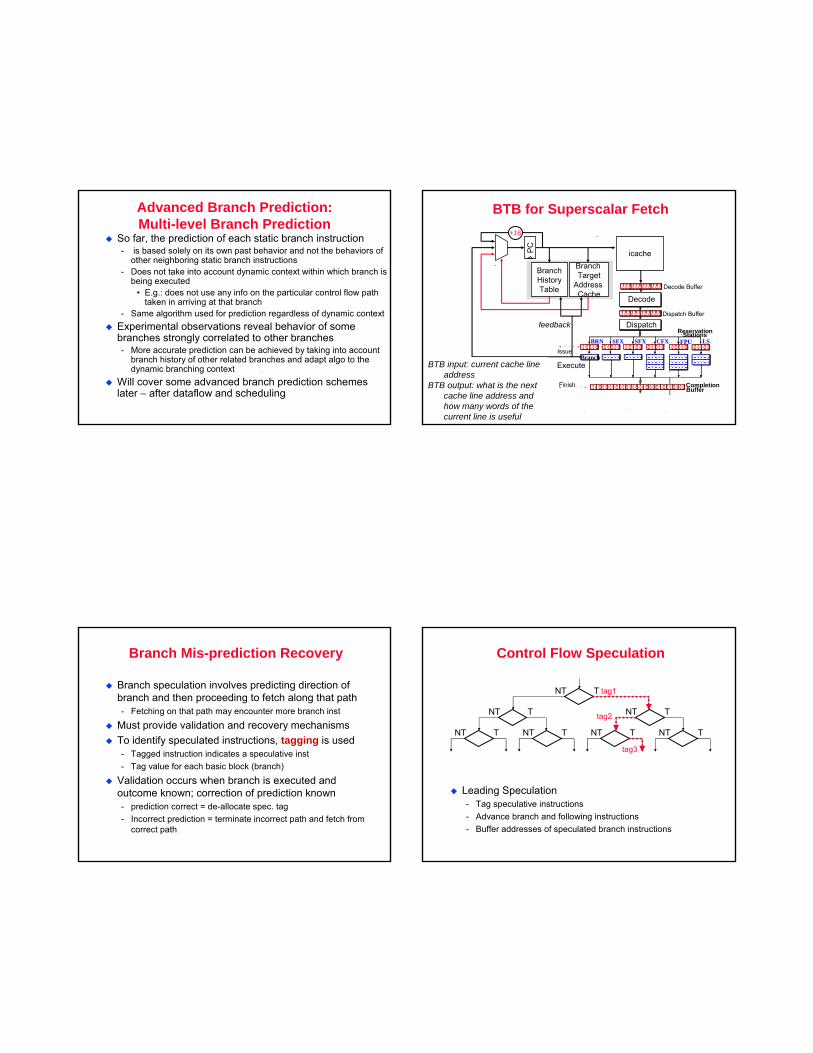
Advanced Branch Prediction:Multi-level Branch Prediction
So far, the prediction of each static branch instruction- is based solely on its own past behavior and not the behaviors of
other neighboring static branch instructions- Does not take into account dynamic context within which branch is
being executed• E.g.: does not use any info on the particular control flow path
taken in arriving at that branch- Same algorithm used for prediction regardless of dynamic context
Experimental observations reveal behavior of some branches strongly correlated to other branches- More accurate prediction can be achieved by taking into account
branch history of other related branches and adapt algo to the dynamic branching context
Will cover some advanced branch prediction schemes later – after dataflow and scheduling
BTB for Superscalar Fetch
Decode Buffer
Dispatch Buffer
Decode
ReservationDispatch
Stations
Issue
Execute
Finish Completion
Branch
SFX SFX CFX FPU LSBRN
Buffer
icachePC
BranchHistoryTable
Branch Target
Address Cache
+16
feedback
BTB input: current cache line address
BTB output: what is the next cache line address and how many words of the current line is useful
Branch Mis-prediction Recovery
Branch speculation involves predicting direction of branch and then proceeding to fetch along that path- Fetching on that path may encounter more branch inst
Must provide validation and recovery mechanismsTo identify speculated instructions, tagging is used- Tagged instruction indicates a speculative inst- Tag value for each basic block (branch)
Validation occurs when branch is executed and outcome known; correction of prediction known- prediction correct = de-allocate spec. tag- Incorrect prediction = terminate incorrect path and fetch from
correct path
Control Flow Speculation
Leading Speculation- Tag speculative instructions - Advance branch and following instructions- Buffer addresses of speculated branch instructions
NT T NT T NT T NT T
NT T NT T
NT T tag1
tag2
tag3
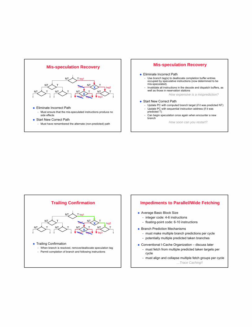
Mis-speculation Recovery
Eliminate Incorrect Path- Must ensure that the mis-speculated instructions produce no
side effects
Start New Correct Path- Must have remembered the alternate (non-predicted) path
NT T NT T NT T NT T
NT T NT T
NT T tag1
tag2
tag3 tag3tag3
tag2
Mis-speculation Recovery
Eliminate Incorrect Path- Use branch tag(s) to deallocate completion buffer entries
occupied by speculative instructions (now determined to be mis-speculated).
- Invalidate all instructions in the decode and dispatch buffers, as well as those in reservation stations
How expensive is a misprediction?
Start New Correct Path- Update PC with computed branch target (if it was predicted NT)- Update PC with sequential instruction address (if it was
predicted T)- Can begin speculation once again when encounter a new
branchHow soon can you restart?
Trailing Confirmation
Trailing Confirmation- When branch is resolved, remove/deallocate speculation tag- Permit completion of branch and following instructions
NT T NT T NT T NT T
NT T NT T
NT T tag1
tag2
tag3tag3 tag3
tag2
Impediments to Parallel/Wide Fetching
Average Basic Block Size- integer code: 4-6 instructions- floating-point code: 6-10 instructions
Branch Prediction Mechanisms- must make multiple branch predictions per cycle- potentially multiple predicted taken branches
Conventional I-Cache Organization – discuss later- must fetch from multiple predicted taken targets per
cycle- must align and collapse multiple fetch groups per cycle
…Trace Caching!!
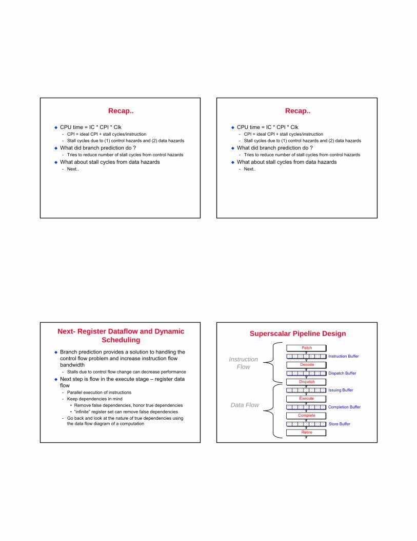
Recap..
CPU time = IC * CPI * Clk- CPI = ideal CPI + stall cycles/instruction- Stall cycles due to (1) control hazards and (2) data hazards
What did branch prediction do ?- Tries to reduce number of stall cycles from control hazards
What about stall cycles from data hazards- Next..
Recap..
CPU time = IC * CPI * Clk- CPI = ideal CPI + stall cycles/instruction- Stall cycles due to (1) control hazards and (2) data hazards
What did branch prediction do ?- Tries to reduce number of stall cycles from control hazards
What about stall cycles from data hazards- Next..
Next- Register Dataflow and Dynamic Scheduling
Branch prediction provides a solution to handling the control flow problem and increase instruction flow bandwidth- Stalls due to control flow change can decrease performance
Next step is flow in the execute stage – register data flow- Parallel execution of instructions- Keep dependencies in mind
• Remove false dependencies, honor true dependencies• “infinite” register set can remove false dependencies
- Go back and look at the nature of true dependencies using the data flow diagram of a computation
Superscalar Pipeline Design
Instruction Buffer
Fetch
Dispatch Buffer
Decode
Issuing Buffer
Dispatch
Completion Buffer
Execute
Store Buffer
Complete
Retire
InstructionFlow
Data Flow
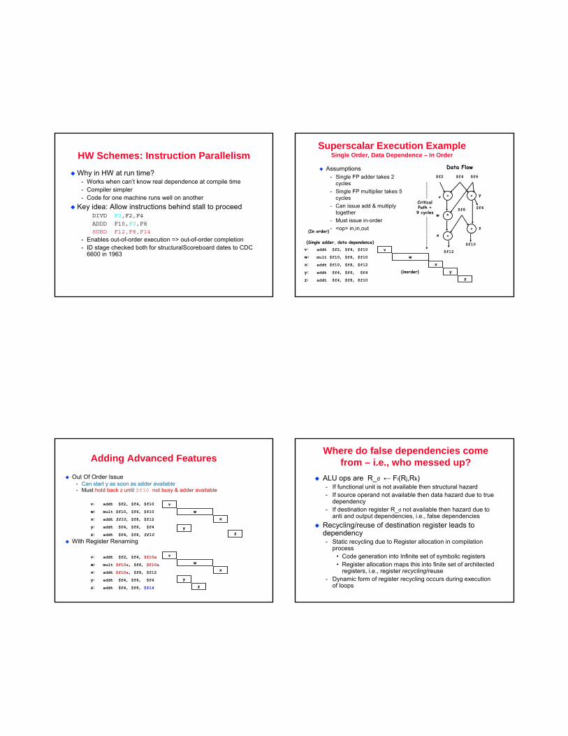
HW Schemes: Instruction ParallelismWhy in HW at run time?
- Works when can’t know real dependence at compile time- Compiler simpler- Code for one machine runs well on another
Key idea: Allow instructions behind stall to proceedDIVD F0,F2,F4
ADDD F10,F0,F8
SUBD F12,F8,F14
- Enables out-of-order execution => out-of-order completion- ID stage checked both for structuralScoreboard dates to CDC
6600 in 1963
Superscalar Execution ExampleSingle Order, Data Dependence – In Order
Assumptions- Single FP adder takes 2
cycles- Single FP multiplier takes 5
cycles- Can issue add & multiply
together- Must issue in-order- <op> in,in,out
v: addt $f2, $f4, $f10
w: mult $f10, $f6, $f10
x: addt $f10, $f8, $f12
y: addt $f4, $f6, $f4
z: addt $f4, $f8, $f10
vw
xy
(Single adder, data dependence)
(In order)
(inorder)
Data Flow
+ +
*
+
$f2 $f4 $f6
$f4
$f10
$f8
yv
xz
CriticalPath =9 cycles
+
w
z
$f12
z
Adding Advanced Features
Out Of Order Issue- Can start y as soon as adder available- Must hold back z until $f10 not busy & adder available
With Register Renaming
vw
x
yz
vw
x
yz
v: addt $f2, $f4, $f10
w: mult $f10, $f6, $f10
x: addt $f10, $f8, $f12
y: addt $f4, $f6, $f4
z: addt $f4, $f8, $f10
v: addt $f2, $f4, $f10a
w: mult $f10a, $f6, $f10a
x: addt $f10a, $f8, $f12
y: addt $f4, $f6, $f4
z: addt $f4, $f8, $f14
Where do false dependencies come from – i.e., who messed up?
ALU ops are R_d ← Fi(Rj,Rk)- If functional unit is not available then structural hazard- If source operand not available then data hazard due to true
dependency- If destination register R_d not available then hazard due to
anti and output dependencies, i.e., false dependenciesRecycling/reuse of destination register leads to dependency- Static recycling due to Register allocation in compilation
process• Code generation into Infinite set of symbolic registers• Register allocation maps this into finite set of architected
registers, i.e., register recycling/reuse- Dynamic form of register recycling occurs during execution
of loops
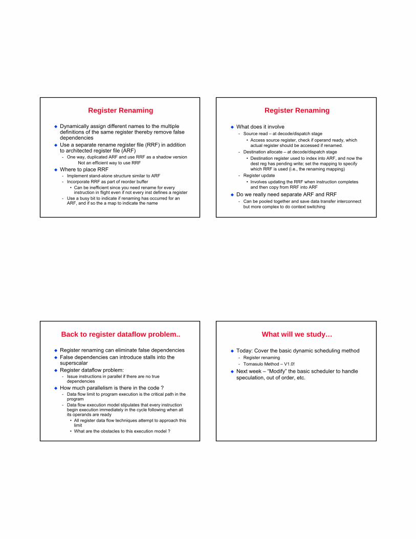
Register Renaming
Dynamically assign different names to the multiple definitions of the same register thereby remove false dependenciesUse a separate rename register file (RRF) in addition to architected register file (ARF)- One way, duplicated ARF and use RRF as a shadow version
Not an efficient way to use RRFWhere to place RRF- Implement stand-alone structure similar to ARF- Incorporate RRF as part of reorder buffer
• Can be inefficient since you need rename for every instruction in flight even if not every inst defines a register
- Use a busy bit to indicate if renaming has occurred for an ARF, and if so the a map to indicate the name
Register Renaming
What does it involve- Source read – at decode/dispatch stage
• Access source register, check if operand ready, which actual register should be accessed if renamed.
- Destination allocate – at decode/dispatch stage• Destination register used to index into ARF, and now the
dest reg has pending write; set the mapping to specify which RRF is used (i.e., the renaming mapping)
- Register update • Involves updating the RRF when instruction completes
and then copy from RRF into ARF
Do we really need separate ARF and RRF- Can be pooled together and save data transfer interconnect
but more complex to do context switching
Back to register dataflow problem..
Register renaming can eliminate false dependenciesFalse dependencies can introduce stalls into the superscalarRegister dataflow problem:- Issue instructions in parallel if there are no true
dependenciesHow much parallelism is there in the code ?- Data flow limit to program execution is the critical path in the
program- Data flow execution model stipulates that every instruction
begin execution immediately in the cycle following when all its operands are ready
• All register data flow techniques attempt to approach this limit
• What are the obstacles to this execution model ?
What will we study…
Today: Cover the basic dynamic scheduling method- Register renaming- Tomasulo Method – V1.0!
Next week – “Modify” the basic scheduler to handle speculation, out of order, etc.
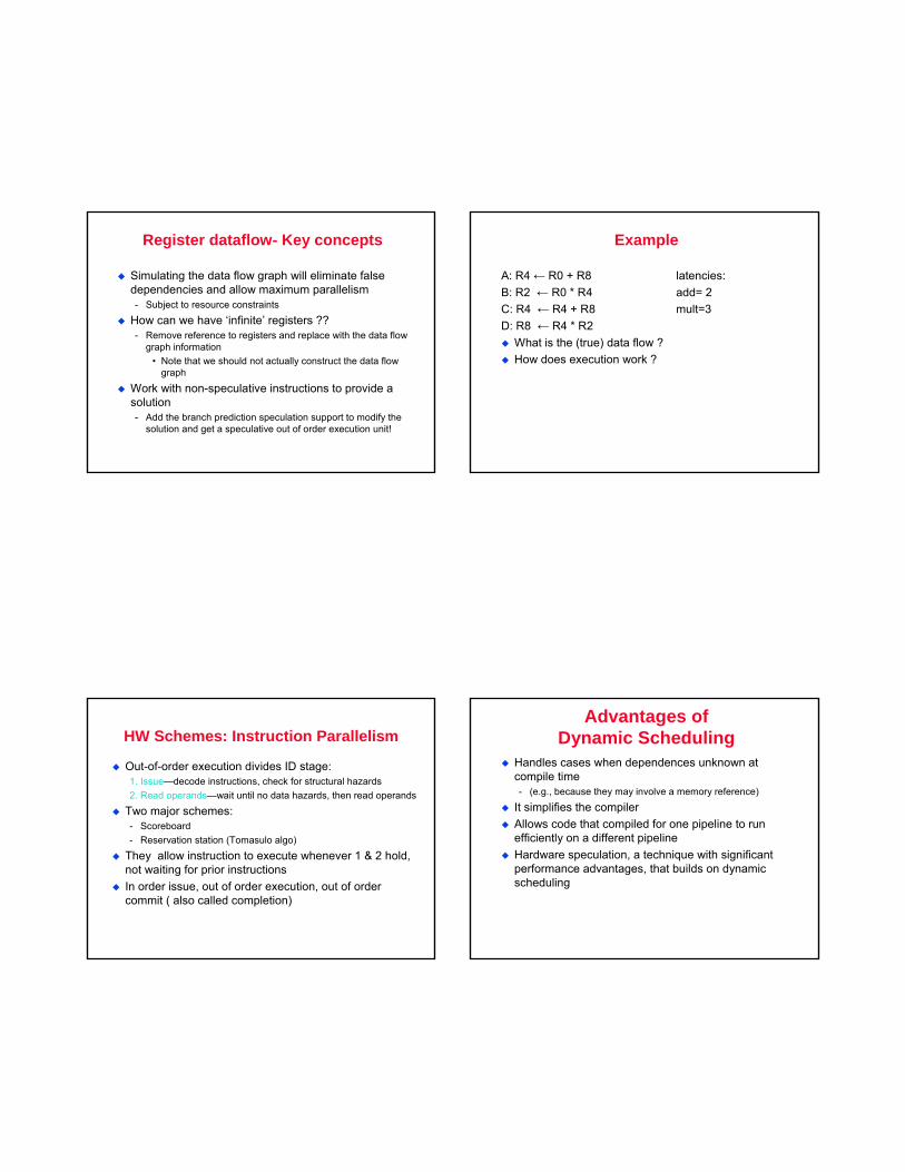
Register dataflow- Key concepts
Simulating the data flow graph will eliminate false dependencies and allow maximum parallelism - Subject to resource constraints
How can we have ‘infinite’ registers ??- Remove reference to registers and replace with the data flow
graph information• Note that we should not actually construct the data flow
graph
Work with non-speculative instructions to provide a solution- Add the branch prediction speculation support to modify the
solution and get a speculative out of order execution unit!
Example
A: R4 ← R0 + R8 latencies:B: R2 ← R0 * R4 add= 2C: R4 ← R4 + R8 mult=3D: R8 ← R4 * R2
What is the (true) data flow ? How does execution work ?
HW Schemes: Instruction Parallelism
Out-of-order execution divides ID stage:1. Issue—decode instructions, check for structural hazards2. Read operands—wait until no data hazards, then read operands
Two major schemes: - Scoreboard- Reservation station (Tomasulo algo)
They allow instruction to execute whenever 1 & 2 hold, not waiting for prior instructionsIn order issue, out of order execution, out of order commit ( also called completion)
Advantages ofDynamic Scheduling
Handles cases when dependences unknown at compile time - (e.g., because they may involve a memory reference)
It simplifies the compiler Allows code that compiled for one pipeline to run efficiently on a different pipeline Hardware speculation, a technique with significant performance advantages, that builds on dynamic scheduling
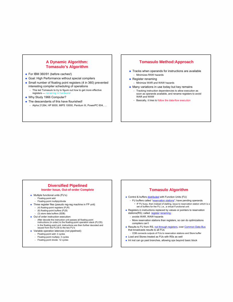
A Dynamic Algorithm: Tomasulo’s Algorithm
For IBM 360/91 (before caches!)Goal: High Performance without special compilersSmall number of floating point registers (4 in 360) prevented interesting compiler scheduling of operations- This led Tomasulo to try to figure out how to get more effective
registers — renaming in hardware!
Why Study 1966 Computer? The descendants of this have flourished!- Alpha 21264, HP 8000, MIPS 10000, Pentium III, PowerPC 604, …
Tomasulo Method:Approach
Tracks when operands for instructions are available- Minimizes RAW hazards
Register renaming- Minimize WAR and WAW hazards
Many variations in use today but key remains- Tracking instruction dependencies to allow execution as
soon as operands available, and rename registers to avoid WAR and WAW
- Basically, it tries to follow the data-flow execution
Diversified PipelinedInorder Issue, Out-of-order Complete
Multiple functional units (FU’s)- Floating-point add- Floating-point multiply/divide
Three register files (pseudo reg-reg machine in FP unit)- (4) floating-point registers (FLR)- (6) floating-point buffers (FLB)- (3) store data buffers (SDB)
Out of order instruction execution:- After decode the instruction unit passes all floating point
instructions (in order) to the floating-point operation stack (FLOS).- In the floating point unit, instructions are then further decoded and
issued from the FLOS to the two FU’sVariable operation latencies (not pipelined):- Floating-point add: 2 cycles - Floating-point multiply: 3 cycles - Floating-point divide: 12 cycles
Tomasulo AlgorithmControl & buffers distributed with Function Units (FU)
- FU buffers called “reservation stations”; have pending operands• IF FU busy, then instead of stalling, issue to reservation station which is a
set of buffers for the FU..i.e., a virtual Functional unitRegisters in instructions replaced by values or pointers to reservation stations(RS); called register renaming ;
- avoids WAR, WAW hazards- More reservation stations than registers, so can do optimizations
compilers can’tResults to FU from RS, not through registers, over Common Data Busthat broadcasts results to all FUs
- CDB connects outputs of FUs to reservation stations and Store bufferLoad and Stores treated as FUs with RSs as wellInt inst can go past branches, allowing ops beyond basic block
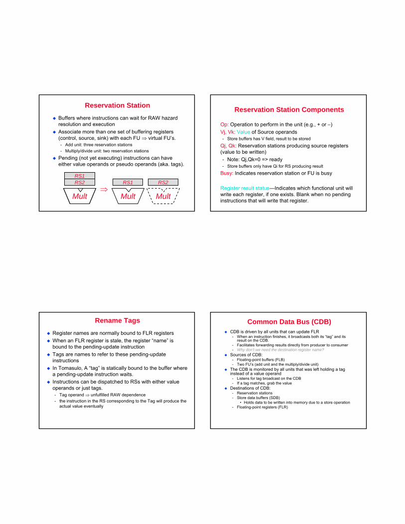
Reservation Station
Buffers where instructions can wait for RAW hazard resolution and executionAssociate more than one set of buffering registers (control, source, sink) with each FU ⇒ virtual FU’s.- Add unit: three reservation stations- Multiply/divide unit: two reservation stations
Pending (not yet executing) instructions can have either value operands or pseudo operands (aka. tags).
Mult
RS2RS1
⇒Mult
RS1
Mult
RS2
Reservation Station Components
Op: Operation to perform in the unit (e.g., + or –)Vj, Vk: Value of Source operands- Store buffers has V field, result to be stored
Qj, Qk: Reservation stations producing source registers (value to be written)- Note: Qj,Qk=0 => ready- Store buffers only have Qi for RS producing result
Busy: Indicates reservation station or FU is busy
Register result status—Indicates which functional unit will write each register, if one exists. Blank when no pending instructions that will write that register.
Rename TagsRegister names are normally bound to FLR registersWhen an FLR register is stale, the register “name” is bound to the pending-update instructionTags are names to refer to these pending-update instructionsIn Tomasulo, A “tag” is statically bound to the buffer where a pending-update instruction waits.Instructions can be dispatched to RSs with either value operands or just tags.- Tag operand ⇒ unfulfilled RAW dependence- the instruction in the RS corresponding to the Tag will produce the
actual value eventually
Common Data Bus (CDB)CDB is driven by all units that can update FLR- When an instruction finishes, it broadcasts both its “tag” and its
result on the CDB.- Facilitates forwarding results directly from producer to consumer- Why don’t we need the destination register name?
Sources of CDB:- Floating-point buffers (FLB)- Two FU’s (add unit and the multiply/divide unit)
The CDB is monitored by all units that was left holding a tag instead of a value operand- Listens for tag broadcast on the CDB- If a tag matches, grab the value
Destinations of CDB:- Reservation stations- Store data buffers (SDB)
• Holds data to be written into memory due to a store operation- Floating-point registers (FLR)
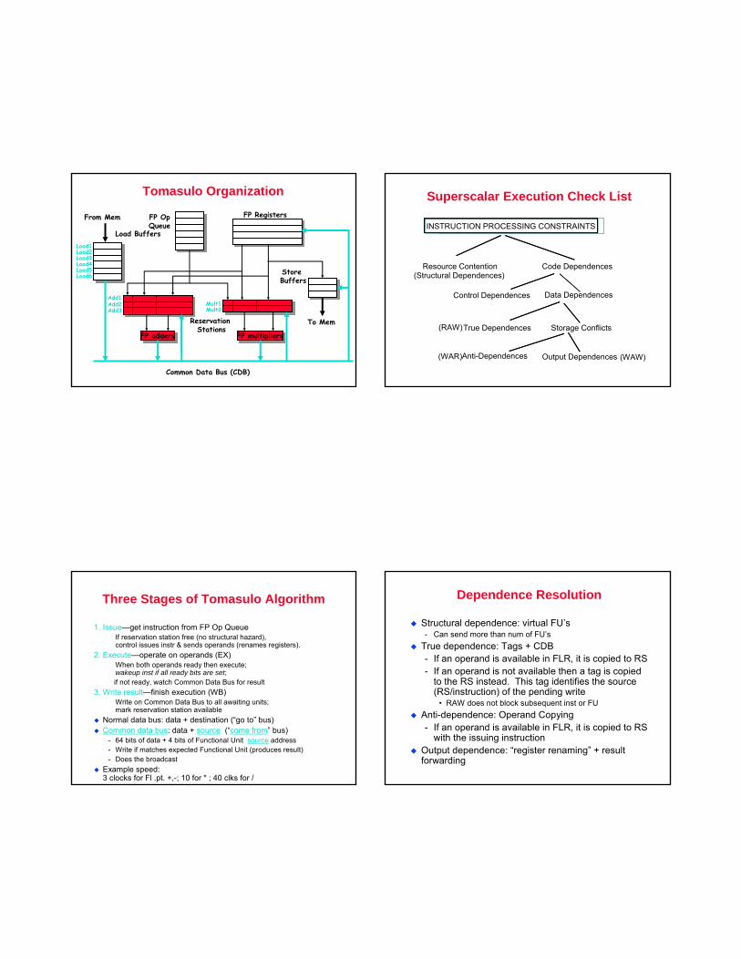
Tomasulo Organization
FP addersFP adders
Add1Add2Add3
FP multipliersFP multipliers
Mult1Mult2
From Mem FP Registers
Reservation Stations
Common Data Bus (CDB)
To Mem
FP OpQueue
Load Buffers
Store Buffers
Load1Load2Load3Load4Load5Load6
Output Dependences (WAW)
Superscalar Execution Check List
INSTRUCTION PROCESSING CONSTRAINTS
Resource Contention Code Dependences
Control Dependences Data Dependences
True Dependences
Anti-Dependences
Storage Conflicts
(Structural Dependences)
(RAW)
(WAR)
Three Stages of Tomasulo Algorithm
1. Issue—get instruction from FP Op QueueIf reservation station free (no structural hazard), control issues instr & sends operands (renames registers).
2. Execute—operate on operands (EX)When both operands ready then execute;wakeup inst if all ready bits are set;if not ready, watch Common Data Bus for result
3. Write result—finish execution (WB)Write on Common Data Bus to all awaiting units; mark reservation station available
Normal data bus: data + destination (“go to” bus)Common data bus: data + source (“come from” bus)
- 64 bits of data + 4 bits of Functional Unit source address- Write if matches expected Functional Unit (produces result)- Does the broadcast
Example speed: 3 clocks for Fl .pt. +,-; 10 for * ; 40 clks for /
Dependence Resolution
Structural dependence: virtual FU’s- Can send more than num of FU’s
True dependence: Tags + CDB- If an operand is available in FLR, it is copied to RS - If an operand is not available then a tag is copied
to the RS instead. This tag identifies the source (RS/instruction) of the pending write
• RAW does not block subsequent inst or FUAnti-dependence: Operand Copying- If an operand is available in FLR, it is copied to RS
with the issuing instructionOutput dependence: “register renaming” + result forwarding
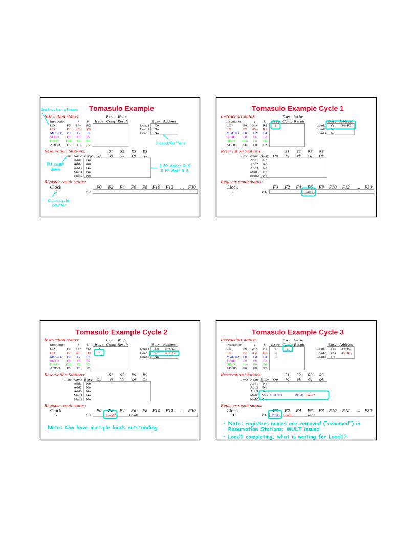
Tomasulo ExampleInstruction status: Exec Write
Instruction j k Issue Comp Result Busy AddressLD F6 34+ R2 Load1 NoLD F2 45+ R3 Load2 NoMULTD F0 F2 F4 Load3 NoSUBD F8 F6 F2DIVD F10 F0 F6ADDD F6 F8 F2
Reservation Stations: S1 S2 RS RSTime Name Busy Op Vj Vk Qj Qk
Add1 NoAdd2 NoAdd3 NoMult1 NoMult2 No
Register result status:Clock F0 F2 F4 F6 F8 F10 F12 ... F30
0 FU
Clock cycle counter
FU countdown
Instruction stream
3 Load/Buffers
3 FP Adder R.S.2 FP Mult R.S.
Tomasulo Example Cycle 1Instruction status: Exec Write
Instruction j k Issue Comp Result Busy AddressLD F6 34+ R2 1 Load1 Yes 34+R2LD F2 45+ R3 Load2 NoMULTD F0 F2 F4 Load3 NoSUBD F8 F6 F2DIVD F10 F0 F6ADDD F6 F8 F2
Reservation Stations: S1 S2 RS RSTime Name Busy Op Vj Vk Qj Qk
Add1 NoAdd2 NoAdd3 NoMult1 NoMult2 No
Register result status:Clock F0 F2 F4 F6 F8 F10 F12 ... F30
1 FU Load1
Tomasulo Example Cycle 2Instruction status: Exec Write
Instruction j k Issue Comp Result Busy AddressLD F6 34+ R2 1 Load1 Yes 34+R2LD F2 45+ R3 2 Load2 Yes 45+R3MULTD F0 F2 F4 Load3 NoSUBD F8 F6 F2DIVD F10 F0 F6ADDD F6 F8 F2
Reservation Stations: S1 S2 RS RSTime Name Busy Op Vj Vk Qj Qk
Add1 NoAdd2 NoAdd3 NoMult1 NoMult2 No
Register result status:Clock F0 F2 F4 F6 F8 F10 F12 ... F30
2 FU Load2 Load1
Note: Can have multiple loads outstanding
Tomasulo Example Cycle 3Instruction status: Exec Write
Instruction j k Issue Comp Result Busy AddressLD F6 34+ R2 1 3 Load1 Yes 34+R2LD F2 45+ R3 2 Load2 Yes 45+R3MULTD F0 F2 F4 3 Load3 NoSUBD F8 F6 F2DIVD F10 F0 F6ADDD F6 F8 F2
Reservation Stations: S1 S2 RS RSTime Name Busy Op Vj Vk Qj Qk
Add1 NoAdd2 NoAdd3 NoMult1 Yes MULTD R(F4) Load2Mult2 No
Register result status:Clock F0 F2 F4 F6 F8 F10 F12 ... F30
3 FU Mult1 Load2 Load1
• Note: registers names are removed (“renamed”) in Reservation Stations; MULT issued
• Load1 completing; what is waiting for Load1?
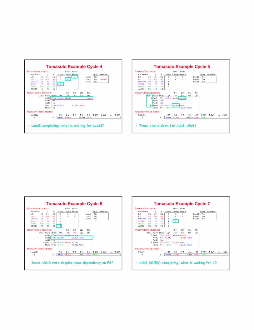
Tomasulo Example Cycle 4Instruction status: Exec Write
Instruction j k Issue Comp Result Busy AddressLD F6 34+ R2 1 3 4 Load1 NoLD F2 45+ R3 2 4 Load2 Yes 45+R3MULTD F0 F2 F4 3 Load3 NoSUBD F8 F6 F2 4DIVD F10 F0 F6ADDD F6 F8 F2
Reservation Stations: S1 S2 RS RSTime Name Busy Op Vj Vk Qj Qk
Add1 Yes SUBD M(A1) Load2Add2 NoAdd3 NoMult1 Yes MULTD R(F4) Load2Mult2 No
Register result status:Clock F0 F2 F4 F6 F8 F10 F12 ... F30
4 FU Mult1 Load2 M(A1) Add1
• Load2 completing; what is waiting for Load2?
Tomasulo Example Cycle 5Instruction status: Exec Write
Instruction j k Issue Comp Result Busy AddressLD F6 34+ R2 1 3 4 Load1 NoLD F2 45+ R3 2 4 5 Load2 NoMULTD F0 F2 F4 3 Load3 NoSUBD F8 F6 F2 4DIVD F10 F0 F6 5ADDD F6 F8 F2
Reservation Stations: S1 S2 RS RSTime Name Busy Op Vj Vk Qj Qk
2 Add1 Yes SUBD M(A1) M(A2)Add2 NoAdd3 No
10 Mult1 Yes MULTD M(A2) R(F4)Mult2 Yes DIVD M(A1) Mult1
Register result status:Clock F0 F2 F4 F6 F8 F10 F12 ... F30
5 FU Mult1 M(A2) M(A1) Add1 Mult2
• Timer starts down for Add1, Mult1
Tomasulo Example Cycle 6Instruction status: Exec Write
Instruction j k Issue Comp Result Busy AddressLD F6 34+ R2 1 3 4 Load1 NoLD F2 45+ R3 2 4 5 Load2 NoMULTD F0 F2 F4 3 Load3 NoSUBD F8 F6 F2 4DIVD F10 F0 F6 5ADDD F6 F8 F2 6
Reservation Stations: S1 S2 RS RSTime Name Busy Op Vj Vk Qj Qk
1 Add1 Yes SUBD M(A1) M(A2)Add2 Yes ADDD M(A2) Add1Add3 No
9 Mult1 Yes MULTD M(A2) R(F4)Mult2 Yes DIVD M(A1) Mult1
Register result status:Clock F0 F2 F4 F6 F8 F10 F12 ... F30
6 FU Mult1 M(A2) Add2 Add1 Mult2
• Issue ADDD here despite name dependency on F6?
Tomasulo Example Cycle 7Instruction status: Exec Write
Instruction j k Issue Comp Result Busy AddressLD F6 34+ R2 1 3 4 Load1 NoLD F2 45+ R3 2 4 5 Load2 NoMULTD F0 F2 F4 3 Load3 NoSUBD F8 F6 F2 4 7DIVD F10 F0 F6 5ADDD F6 F8 F2 6
Reservation Stations: S1 S2 RS RSTime Name Busy Op Vj Vk Qj Qk
0 Add1 Yes SUBD M(A1) M(A2)Add2 Yes ADDD M(A2) Add1Add3 No
8 Mult1 Yes MULTD M(A2) R(F4)Mult2 Yes DIVD M(A1) Mult1
Register result status:Clock F0 F2 F4 F6 F8 F10 F12 ... F30
7 FU Mult1 M(A2) Add2 Add1 Mult2
• Add1 (SUBD) completing; what is waiting for it?
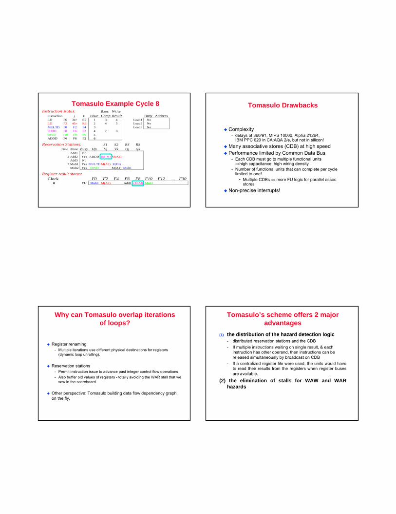
Tomasulo Example Cycle 8Instruction status: Exec Write
Instruction j k Issue Comp Result Busy AddressLD F6 34+ R2 1 3 4 Load1 NoLD F2 45+ R3 2 4 5 Load2 NoMULTD F0 F2 F4 3 Load3 NoSUBD F8 F6 F2 4 7 8DIVD F10 F0 F6 5ADDD F6 F8 F2 6
Reservation Stations: S1 S2 RS RSTime Name Busy Op Vj Vk Qj Qk
Add1 No2 Add2 Yes ADDD (M-M) M(A2)
Add3 No7 Mult1 Yes MULTD M(A2) R(F4)
Mult2 Yes DIVD M(A1) Mult1
Register result status:Clock F0 F2 F4 F6 F8 F10 F12 ... F30
8 FU Mult1 M(A2) Add2 (M-M) Mult2
Tomasulo Drawbacks
Complexity- delays of 360/91, MIPS 10000, Alpha 21264,
IBM PPC 620 in CA:AQA 2/e, but not in silicon!Many associative stores (CDB) at high speedPerformance limited by Common Data Bus
- Each CDB must go to multiple functional units ⇒high capacitance, high wiring density
- Number of functional units that can complete per cycle limited to one!
• Multiple CDBs ⇒ more FU logic for parallel assoc stores
Non-precise interrupts!
Why can Tomasulo overlap iterations of loops?
Register renaming- Multiple iterations use different physical destinations for registers
(dynamic loop unrolling).
Reservation stations - Permit instruction issue to advance past integer control flow operations- Also buffer old values of registers - totally avoiding the WAR stall that we
saw in the scoreboard.
Other perspective: Tomasulo building data flow dependency graph on the fly.
Tomasulo’s scheme offers 2 major advantages
(1) the distribution of the hazard detection logic- distributed reservation stations and the CDB- If multiple instructions waiting on single result, & each
instruction has other operand, then instructions can be released simultaneously by broadcast on CDB
- If a centralized register file were used, the units would have to read their results from the registers when register buses are available.
(2) the elimination of stalls for WAW and WAR hazards
Relationship between precise interrupts and speculation:
Speculation is a form of guessing.Important for branch prediction:- Need to “take our best shot” at predicting branch direction.
If we speculate and are wrong, need to back up and restart execution to point at which we predicted incorrectly:- This is exactly same as precise exceptions!
Technique for both precise interrupts/exceptions and speculation: in-order completion or commit
Multiple Issue ILP Processors
In statically scheduled superscalar instructions issue in order, and all pipeline hazards checked at issue time- Inst causing hazard will force subsequent inst to be stalled
In statically scheduled VLIW, compiler generates multiple issue packets of instructionsDuring instruction fetch, pipeline receives number of inst from IF stage – issue packet- Examine each inst in packet: if no hazard then issue else
wait- Issue unit examines all inst in packet
• Complexity implies further splitting of issue stage
Multiple Issue
To issue multiple instructions per clock, key is assigning reservation station and updating pipeline control tablesTwo approaches- Run this step in half a clock cycle; two inst can be processed
in one clock cycle- Build logic needed to handle two instructions at once
Dynamic Scheduling – Dynamic Execution core
Current superscalar processors provide “out of order”- Architecture is an out of order core sandwiched between in-
order front-end and in-order back-end- In-order front end
• Fetches and dispatches instructions in program order- In-order back-end
• Completes and retires inst in program order- Dynamic execution core
• Refinement of Tomasulo method• Has three parts
− Instruction dispatch: rename reg, alloc. Res.stations− Inst execution: exec., forward results− Instruction completion:
Extending Tomasulo
Have to allow for speculative instructions- Separate bypassing of results among instructions from the
actual completion of instruction
Tag instructions as speculative until they are validated – and then commit the instructionKey idea: allow instructions to execute out of order but commit in order- Requires reorder buffer (ROB) to hold and pass results
among speculated instructions- ROB is a source of operands- Register file is not updated until instruction commits
• Therefore ROB supplies operands in interval between completion of inst and commit of inst
Reorder Buffer (ROB)
Reorder buffer contains all instructions in flight, i.e., all inst dispatched but not completed- Inst waiting in reservation stations- Executing in functional units- Finished execution but waiting to be completed in program
order
Status of each instruction can be tracked using several bits in each entry in ROB- Additional bit to indicate if instruction is speculative- Only finished and non-speculative can be committed- Instruction marked invalid is not architecturally completed
when exiting the reorder buffer
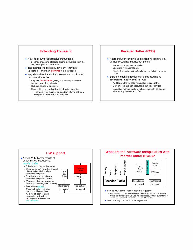
HW supportNeed HW buffer for results of uncommitted instructions: reorder buffer
- 3 fields: instr, destination, value- Use reorder buffer number instead
of reservation station when execution completes
- Supplies operands between execution complete & commit
- (Reorder buffer can be operand source => more registers like RS)
- Instructions commit- Once instruction commits,
result is put into register- As a result, easy to undo
speculated instructions on mispredicted branches or exceptions
ReorderBuffer
FPOp
Queue
FP Adder FP Adder
Res Stations Res Stations
FP Regs
What are the hardware complexities with reorder buffer (ROB)?
ReorderBuffer
FPOp
Queue
FP Adder FP Adder
Res Stations Res Stations
FP Regs
Compar
network
How do you find the latest version of a register?- (As specified by Smith paper) need associative comparison network- Could use future file or just use the register result status buffer to track
which specific reorder buffer has received the valueNeed as many ports on ROB as register file
Reorder Table
Des
tRe
g
Resu
lt
Exce
ptions
?
Valid
Prog
ram C
ount
er
Four Steps of Speculative Tomasulo Algorithm
1. Issue—get instruction from FP Op QueueIf reservation station and reorder buffer slot free, issue instr & send operands & reorder buffer no. for destination (this stage sometimes called “dispatch”)
2. Execution—operate on operands (EX)When both operands ready then execute; if not ready, watch CDB for result; when both in reservation station, execute; checks RAW (sometimes called “issue”)
3. Write result—finish execution (WB)Write on Common Data Bus to all awaiting FUs& reorder buffer; mark reservation station available.
4. Commit—update register with reorder resultWhen instr. at head of reorder buffer & result present, update register with result (or store to memory) and remove instr from reorder buffer. Mispredicted branch flushes reorder buffer (sometimes called “graduation”)
SummaryReservations stations: implicit register renaming to larger set of registers + buffering source operands
- Prevents registers as bottleneck- Avoids WAR, WAW hazards of Scoreboard- Allows loop unrolling in HW
Not limited to basic blocks (integer units gets ahead, beyond branches)Lasting Contributions
- Dynamic scheduling- Register renaming- Load/store disambiguation
360/91 descendants are Pentium III; PowerPC 604; MIPS R10000; HP-PA 8000; Alpha 21264
More branch prediction Inter-relating Branches
So far, not considered inter-dependent branches- Branches whose outcome depends on other branches
If (a<=0) then { s1}; /* branch b1 */If (a>0) then {s2}; /* branch b2 */
Relation between b1 and b2 ?
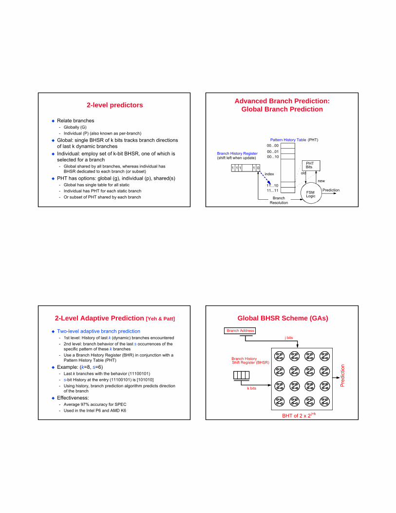
2-level predictors
Relate branches- Globally (G)- Individual (P) (also known as per-branch)
Global: single BHSR of k bits tracks branch directions of last k dynamic branchesIndividual: employ set of k-bit BHSR, one of which is selected for a branch- Global shared by all branches, whereas individual has
BHSR dedicated to each branch (or subset)
PHT has options: global (g), individual (p), shared(s)- Global has single table for all static- Individual has PHT for each static branch- Or subset of PHT shared by each branch
Advanced Branch Prediction:Global Branch Prediction
00...0000...0100...10
11...1011...11
1 1 1 1 0
Branch History Register(shift left when update)
Pattern History Table (PHT)
PHTBits
Prediction
BranchResolution
index
FSMLogic
old
new
2-Level Adaptive Prediction [Yeh & Patt]
Two-level adaptive branch prediction- 1st level: History of last k (dynamic) branches encountered- 2nd level: branch behavior of the last s occurrences of the
specific pattern of these k branches- Use a Branch History Register (BHR) in conjunction with a
Pattern History Table (PHT)
Example: (k=8, s=6)- Last k branches with the behavior (11100101)- s-bit History at the entry (11100101) is [101010]- Using history, branch prediction algorithm predicts direction
of the branch
Effectiveness:- Average 97% accuracy for SPEC- Used in the Intel P6 and AMD K6
Global BHSR Scheme (GAs)
Pre
dict
ion
Branch Address
Branch HistoryShift Register (BHSR)
j bits
k bits
BHT of 2 x 2 j+k
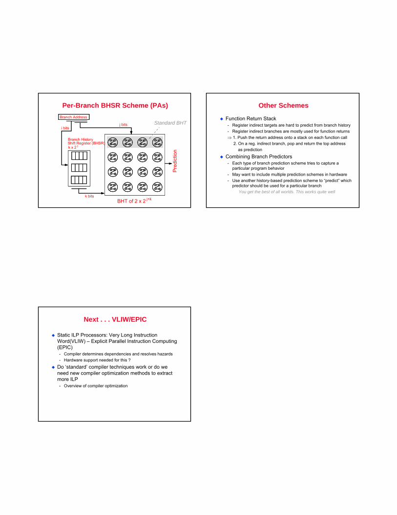
Per-Branch BHSR Scheme (PAs)
Pre
dict
ion
Branch Address
Branch HistoryShift Register (BHSR)
BHT of 2 x 2 j+k
j bits
k bits
i bits
k x 2 i
Standard BHT
Other Schemes
Function Return Stack- Register indirect targets are hard to predict from branch history- Register indirect branches are mostly used for function returns⇒ 1. Push the return address onto a stack on each function call
2. On a reg. indirect branch, pop and return the top address as prediction
Combining Branch Predictors- Each type of branch prediction scheme tries to capture a
particular program behavior- May want to include multiple prediction schemes in hardware- Use another history-based prediction scheme to “predict” which
predictor should be used for a particular branchYou get the best of all worlds. This works quite well
Next . . . VLIW/EPIC
Static ILP Processors: Very Long Instruction Word(VLIW) – Explicit Parallel Instruction Computing (EPIC)- Compiler determines dependencies and resolves hazards- Hardware support needed for this ?
Do ‘standard’ compiler techniques work or do we need new compiler optimization methods to extract more ILP- Overview of compiler optimization