
F E A T U R E S
• Multivariable two-wire, 24 VDC loop-poweredtransmitter for level, volume, or flow
• Performance not process dependent (changingspecific gravity and dielectric have no effect)
• 26 GHz operating frequency offers superior perform-ance with better accuracy and enhanced resolution
• Antenna designs to +400 °C (+750 °F),-1.0 to 160 bar (-14.7 to 2320 psi)
• Range up to 40 m (130')
• Quick connect/disconnect antenna coupling allowsvessel to remain sealed
• 4-button keypad and graphic LCD display allow forconvenient viewing of configuration parameters andecho curve
• Proactive diagnostics advise not only what is wrong,but also offer troubleshooting tips
• Convenient Setup, Optimization, and Echo RejectionWizards (Echo Rejection setup is simple, intuitive,and effective)
• SIL 2 capable (93.2 % SFF, with full FMEDA reportavailable)
• PACTware™ PC Program and enhanced DTMs foradvanced configuration and troubleshooting
• Available with HART® or FOUNDATION fieldbus™
digital outputs
D E S C R I P T I O N
The Pulsar® Model R86 radar transmitter is the latest
generation of Magnetrol® 24 VDC, loop-powered, non-
contact radar transmitters. Enhanced performance,
proactive diagnostics, and various configuration wizards
bring simplicity to an often complex technology.
This latest entry into the radar level measurement field
is designed to provide unparalleled performance and
ease of use. The 26 GHz PULSAR Model R86 is the per-
fect complement to the 6 GHz PULSAR Model R96 and
Eclipse® Model 706 GWR transmitters. Together, this
transmitter family offers the ultimate solution set to
those difficult industrial process level applications.
T E C H N O L O G Y
The PULSAR Model R86 radar transmitter is based on
pulse burst radar technology combined with equivalent
time sampling circuitry. Short bursts of 26 GHz
microwave energy are emitted and subsequently reflect-
ed from the liquid level surface. Distance is first meas-
ured by the equation:
D = Transit time (round-trip)/2.
Liquid level is then calculated based on transmitter
configuration.
A P P L I C A T I O N S
MEDIA: Liquids and slurries; hydrocarbons to water-
based media (dielectric 1.7–100, 1.4 in stillwell)
VESSELS: Most process or storage vessels up to rated
temperature and pressure. Pits and sumps as well as
glass-lined tanks.
CONDITIONS: Virtually all level measurement and con-
trol applications including process conditions exhibiting
varying specific gravity and dielectric, visible vapors,
high fill/empty rates, turbulence, low to moderate foam
and buildup.
Pulsar® Model R86
26 GHz Pulse Burst Radar
Level Transmitter
T E C H N O L O G Y
P U L S E B U R S T R A D A R
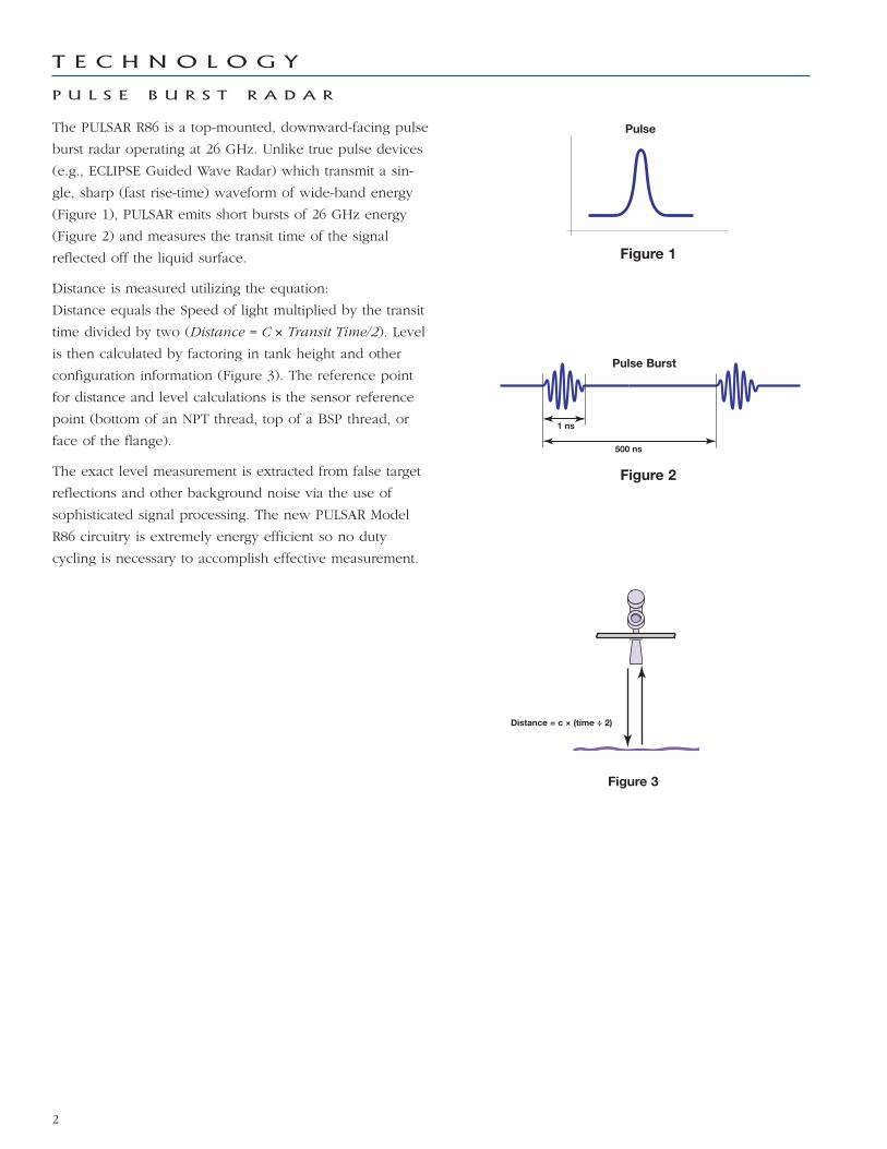
The PULSAR R86 is a top-mounted, downward-facing pulse
burst radar operating at 26 GHz. Unlike true pulse devices
(e.g., ECLIPSE Guided Wave Radar) which transmit a sin-
gle, sharp (fast rise-time) waveform of wide-band energy
(Figure 1), PULSAR emits short bursts of 26 GHz energy
(Figure 2) and measures the transit time of the signal
reflected off the liquid surface.
Distance is measured utilizing the equation:
Distance equals the Speed of light multiplied by the transit
time divided by two (Distance = C × Transit Time/2). Level
is then calculated by factoring in tank height and other
configuration information (Figure 3). The reference point
for distance and level calculations is the sensor reference
point (bottom of an NPT thread, top of a BSP thread, or
face of the flange).
The exact level measurement is extracted from false target
reflections and other background noise via the use of
sophisticated signal processing. The new PULSAR Model
R86 circuitry is extremely energy efficient so no duty
cycling is necessary to accomplish effective measurement.
Figure 3
2
Figure 1
Figure 2
Pulse
Pulse Burst
1 ns
500 ns
Distance = c × (time ÷ 2)
Since larger horns yield stronger signals and smaller beam
angles, the 4" horn antenna should ideally be used to
ensure the best possible performance in all operational
conditions. However, as that is often impractical, other
antenna sizes are available.
The chart below (Figure 5) shows the maximum measuring
range of each antenna based on dielectric and turbulence.
Obstructions, noise and media buildup can drastically
decrease reliable measurement. Although it is theoretically
possible to measure a liquid level on the antenna, liquid
should not be allowed closer than 50 mm (2") from the
bottom of the antenna or 300 mm (12") from the sensor
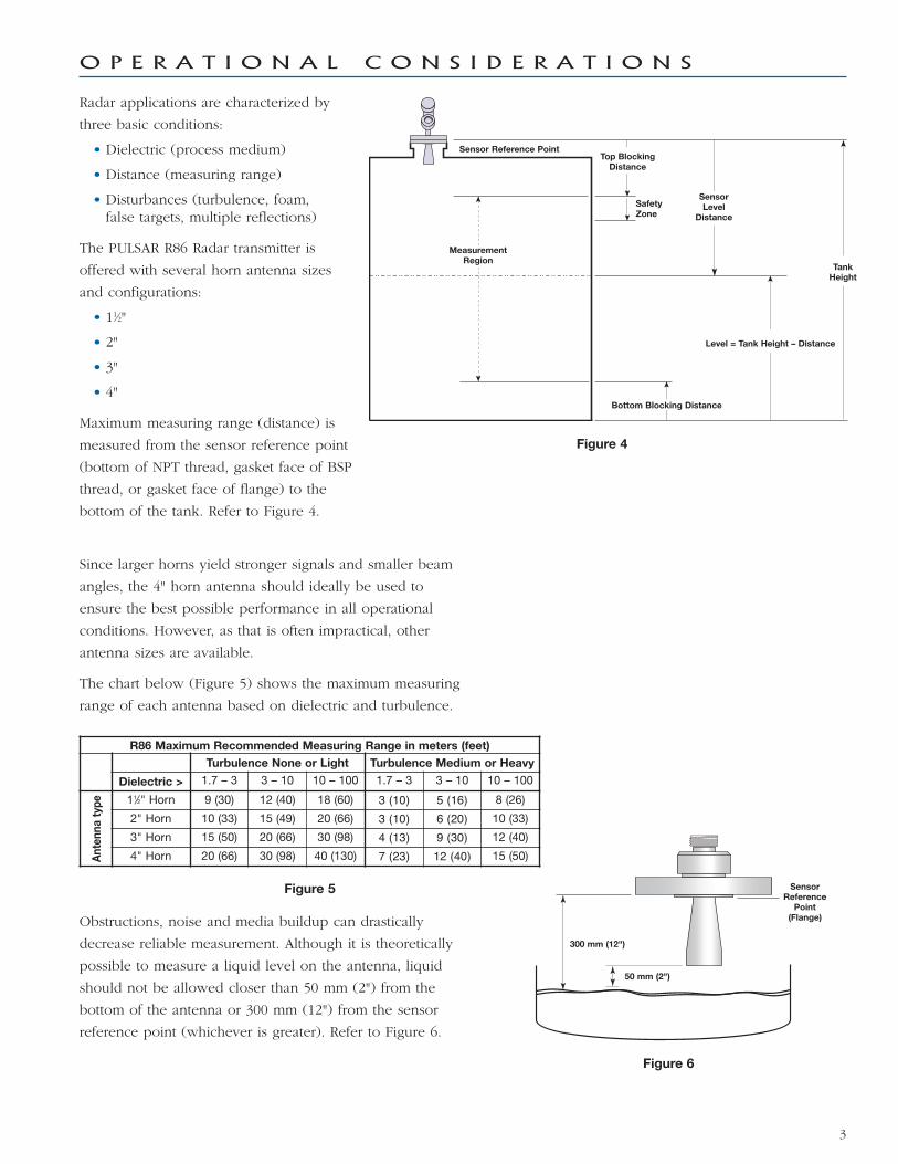
reference point (whichever is greater). Refer to Figure 6.
Figure 5
3
R86 Maximum Recommended Measuring Range in meters (feet)
Turbulence None or Light Turbulence Medium or Heavy
Dielectric > 1.7 – 3 3 – 10 10 – 100 1.7 – 3 3 – 10 10 – 100
An
ten
na
typ
e 11⁄2" Horn 9 (30) 12 (40) 18 (60) 3 (10) 5 (16) 8 (26)
2" Horn 10 (33) 15 (49) 20 (66) 3 (10) 6 (20) 10 (33)
3" Horn 15 (50) 20 (66) 30 (98) 4 (13) 9 (30) 12 (40)
4" Horn 20 (66) 30 (98) 40 (130) 7 (23) 12 (40) 15 (50)
Figure 6
O P E R A T I O N A L C O N S I D E R A T I O N S
Figure 4
Radar applications are characterized by
three basic conditions:
• Dielectric (process medium)
• Distance (measuring range)
• Disturbances (turbulence, foam,false targets, multiple reflections)
The PULSAR R86 Radar transmitter is
offered with several horn antenna sizes
and configurations:
• 11⁄2"
• 2"
• 3"
• 4"
Maximum measuring range (distance) is
measured from the sensor reference point
(bottom of NPT thread, gasket face of BSP
thread, or gasket face of flange) to the
bottom of the tank. Refer to Figure 4.
MeasurementRegion
Top BlockingDistance
TankHeight
SafetyZone
Sensor Reference Point
SensorLevel
Distance
Level = Tank Height – Distance
Bottom Blocking Distance
SensorReference
Point(Flange)
50 mm (2")
300 mm (12")
The PULSAR Model R86 Radar transmitter can be mounted
on a vessel using a variety of process connections.
Generally either a threaded or flanged connection is used.
L O C A T I O N
Ideally, the Radar transmitter should be mounted 1⁄2 radius
from center of the tank providing an unobstructed signal
path to the liquid surface where it can illuminate (with
microwave energy) the largest possible surface area. A
conservative recommendation is to not install in center of
tank top or within 45 cm (18") of tank wall. Tank walls
may produce reflections that must be minimized during
field configuration. Refer to Figure 7.
B E A M A N G L E
The various antenna sizes exhibit different beam patterns.
Figure 9 shows the beam spread for all PULSAR Model R86
antennas. Ideally the beam pattern should illuminate the
maximum liquid surface with minimum striking of other
objects in the vessel including the tank wall. Use these
drawings to determine the optimum installation location.
O B S T R U C T I O N S
Almost any object that falls within the beam pattern will
cause reflections that may be misinterpreted as a false liq-
uid level. Although the PULSAR Model R86 has a power-
ful Echo Rejection routine, all possible precautions should
be taken to minimize false target reflections with proper
installation location. Refer to Figures 8 & 9.
D
W
∝
Beam Spread, W @-3dB; m (ft)
AntennaBeam Angle
(∝)
11⁄2" Horn20°
2" Horn18°
3" Horn11°
4" Horn9°
Distance, D ; m (ft)
3 (10) 1,1 (3.5) 1,0 (3.2) 0,6 (1.9) 0,5 (1.6)
6 (20) 2,1 (7.1) 1,9 (6.3) 1,2 (3.9) 0,9 (3.1)
9 (30) 3,2 (10.6) 2,9 (9.5) 1,7 (5.8) 1,4 (4.7)
12 (40) 4,2 (14.1) 3,8 (12.7) 2,3 (7.7) 1,9 (6.3)
15 (50) 5,3 (17.6) 4,8 (15.8) 2,9 (9.6) 2,4 (7.9)
18 (60) 6,3 (21.2) 5,7 (19.0) 3,5 (11.6) 2,8 (9.4)
20 (65) 6,3 (20.6) 3,9 (12.5) 3,1 (10.2)
30 (98) 5,8 (18.9) 4,7 (15.4)40 (130) 6,3 (20.5)
Figure 7
M O U N T I N G
Figure 8 Figure 94
>45 cm(>18")
1/2Radius
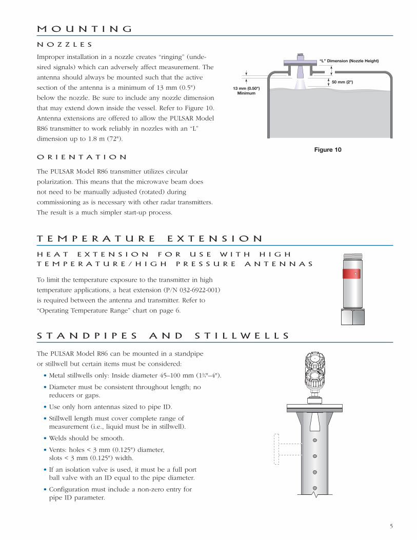
N O Z Z L E S
Improper installation in a nozzle creates “ringing” (unde-
sired signals) which can adversely affect measurement. The
antenna should always be mounted such that the active
section of the antenna is a minimum of 13 mm (0.5")
below the nozzle. Be sure to include any nozzle dimension
that may extend down inside the vessel. Refer to Figure 10.
Antenna extensions are offered to allow the PULSAR Model
R86 transmitter to work reliably in nozzles with an “L”
dimension up to 1.8 m (72").
O R I E N T A T I O N
The PULSAR Model R86 transmitter utilizes circular
polarization. This means that the microwave beam does
not need to be manually adjusted (rotated) during
commissioning as is necessary with other radar transmitters.
The result is a much simpler start-up process.
M O U N T I N G
5
Figure 10
To limit the temperature exposure to the transmitter in high
temperature applications, a heat extension (P/N 032-6922-001)
is required between the antenna and transmitter. Refer to
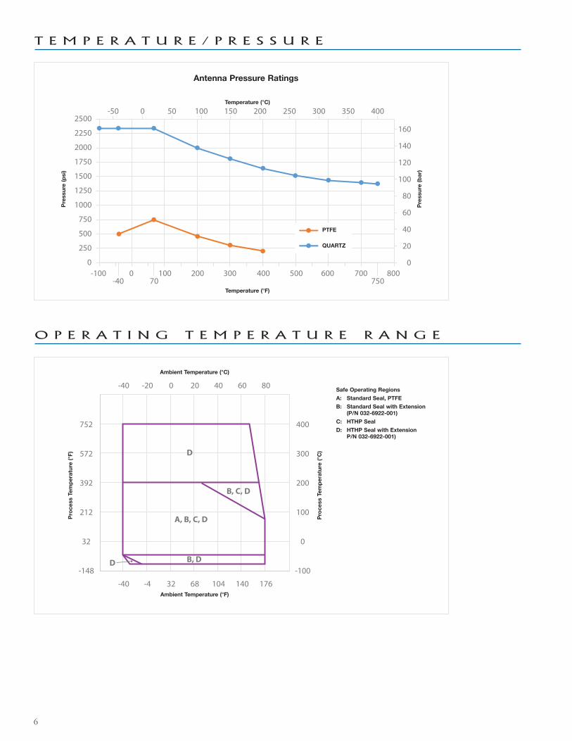
“Operating Temperature Range” chart on page 6.
T E M P E R A T U R E E X T E N S I O N
H E A T E X T E N S I O N F O R U S E W I T H H I G H
T E M P E R A T U R E / H I G H P R E S S U R E A N T E N N A S
The PULSAR Model R86 can be mounted in a standpipe
or stillwell but certain items must be considered:
• Metal stillwells only: Inside diameter 45–100 mm (13⁄4"–4").
• Diameter must be consistent throughout length; noreducers or gaps.
• Use only horn antennas sized to pipe ID.
• Stillwell length must cover complete range ofmeasurement (i.e., liquid must be in stillwell).
• Welds should be smooth.
• Vents: holes < 3 mm (0.125") diameter,slots < 3 mm (0.125") width.
• If an isolation valve is used, it must be a full portball valve with an ID equal to the pipe diameter.
• Configuration must include a non-zero entry forpipe ID parameter.
S T A N D P I P E S A N D S T I L L W E L L S
50 mm (2")
13 mm (0.50")Minimum
“L” Dimension (Nozzle Height)
6
T E M P E R A T U R E / P R E S S U R E
O P E R A T I N G T E M P E R A T U R E R A N G E
0
500
250
-40 70 750
750
1000
1500
1250
2000
2250
1750
2500
-100 0 100 200 300 400 500 600 700 8000
20
40
60
80
100
120
140
160
-50 0 50 100 150 200 250 300 350 400
-148
32
212
392
572
752
-100
0
100
200
300
400
-40 -4 32 68 104 140 176
-40 -20 0 20 40 60 80
D
B, C, D
B, DD
A, B, C, D
Antenna Pressure Ratings
Temperature (°C)
Ambient Temperature (°C)
Safe Operating Regions
A: Standard Seal, PTFE
B: Standard Seal with Extension (P/N 032-6922-001)
C: HTHP Seal
D: HTHP Seal with ExtensionP/N 032-6922-001)
Ambient Temperature (°F)
Pro
ce
ss T
em
pe
ratu
re (
°F)
Pro
ce
ss T
em
pe
ratu
re (
°C)
PTFE
QUARTZ
Pre
ssu
re (
psi)
Pre
ssu
re (
ba
r)
Temperature (°F)
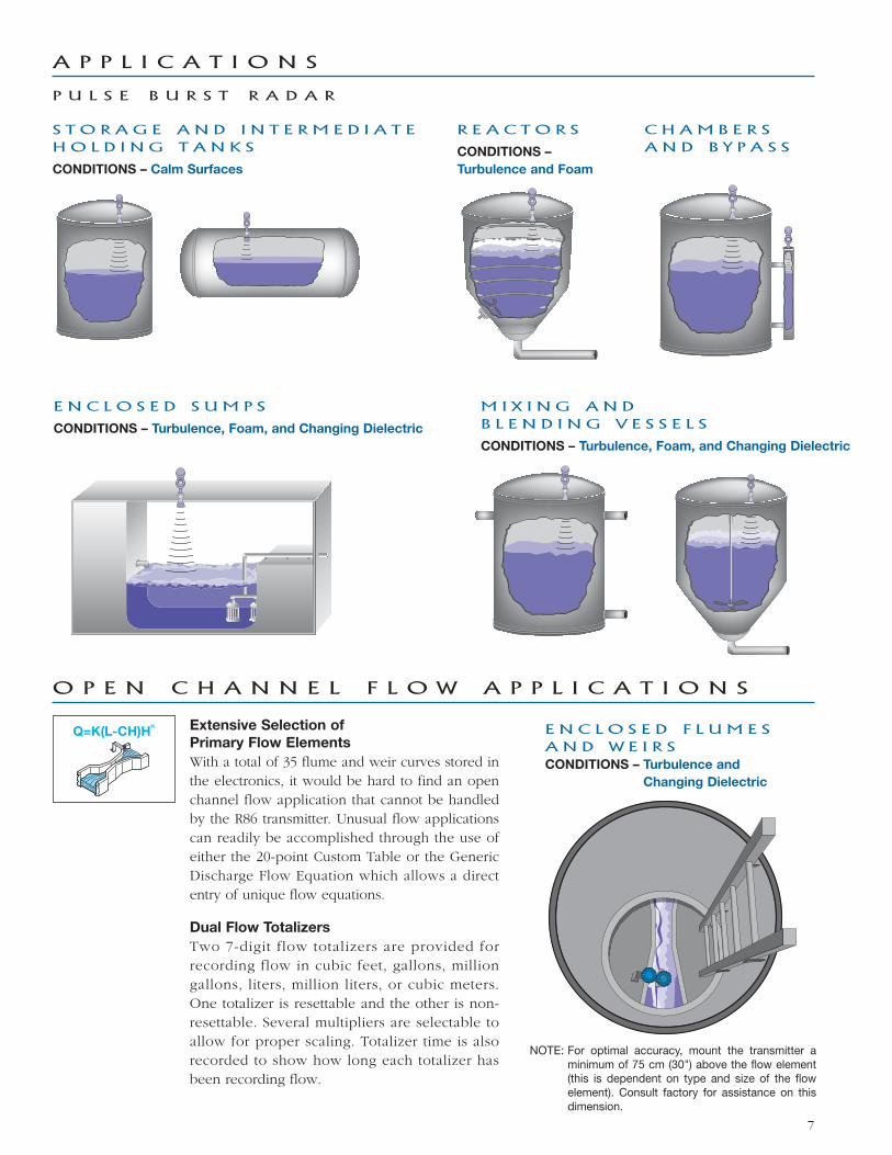
A P P L I C A T I O N S
P U L S E B U R S T R A D A R
R E A C T O R S
CONDITIONS –
Turbulence and Foam
E N C L O S E D S U M P S
CONDITIONS – Turbulence, Foam, and Changing Dielectric
7
M I X I N G A N DB L E N D I N G V E S S E L S
CONDITIONS – Turbulence, Foam, and Changing Dielectric
C H A M B E R SA N D B Y P A S S
S T O R A G E A N D I N T E R M E D I A T EH O L D I N G T A N K S
CONDITIONS – Calm Surfaces
E N C L O S E D F L U M E SA N D W E I R SCONDITIONS – Turbulence and
Changing Dielectric
Extensive Selection of
Primary Flow Elements
With a total of 35 flume and weir curves stored inthe electronics, it would be hard to find an openchannel flow application that cannot be handledby the R86 transmitter. Unusual flow applicationscan readily be accomplished through the use ofeither the 20-point Custom Table or the GenericDischarge Flow Equation which allows a directentry of unique flow equations.
Dual Flow Totalizers
Two 7-digit flow totalizers are provided forrecording flow in cubic feet, gallons, milliongallons, liters, million liters, or cubic meters.One totalizer is resettable and the other is non-resettable. Several multipliers are selectable toallow for proper scaling. Totalizer time is alsorecorded to show how long each totalizer hasbeen recording flow.
Q=K(L-CH)Hn
O P E N C H A N N E L F L O W A P P L I C A T I O N S
NOTE: For optimal accuracy, mount the transmitter aminimum of 75 cm (30") above the flow element(this is dependent on type and size of the flowelement). Consult factory for assistance on thisdimension.
P R O B L E M A T I C A P P L I C A T I O N S
G U I D E D W A V E R A D A R A L T E R N A T I V E
Some applications can be problematic for Non-ContactRadar. The following are examples of when Guided WaveRadar is recommended.
• Extremely low dielectric media (εr<1.7)
• Very weak reflections from the liquid surface (particularly during turbulence) can cause poor performance.
• Tanks heavily cluttered with false targets (mixers,pumps, ladders, pipes, etc.)
• During times of very low liquid levels of low dielectricmedia, the metal tank bottom may be detected, whichcan deteriorate performance.
• Foam can either absorb or reflect the microwave ener-gy depending upon the depth, dielectric, density andwall thickness of the bubbles. Due to typical variationsin the amount (depth) of foam, it is impossible toquantify performance. It may bepossible to receive most, some or none of thetransmitted energy.
• Extremely high liquid level (Overflow) conditionswhen liquid very near the antenna can causeerroneous readings and measurement failure.
• Interface applications
Refer to ECLIPSE Model 706 Guided Wave Radar bulletin BE 57-106.
8
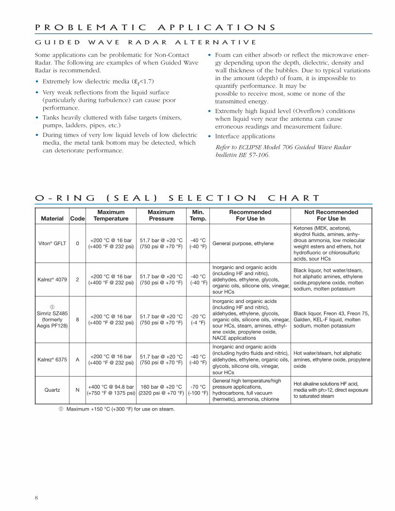
Material CodeMaximum
TemperatureMaximumPressure
Min.Temp.
RecommendedFor Use In
Not RecommendedFor Use In
Viton® GFLT 0+200 °C @ 16 bar(+400 °F @ 232 psi)
51.7 bar @ +20 °C(750 psi @ +70 °F)
-40 °C(-40 °F)
General purpose, ethylene
Ketones (MEK, acetone), skydrol fluids, amines, anhy-drous ammonia, low molecularweight esters and ethers, hothydrofluoric or chlorosulfuricacids, sour HCs
Kalrez® 4079 2+200 °C @ 16 bar(+400 °F @ 232 psi)
51.7 bar @ +20 °C(750 psi @ +70 °F)
-40 °C (-40 °F)
Inorganic and organic acids (including HF and nitric), aldehydes, ethylene, glycols,organic oils, silicone oils, vinegar,sour HCs
Black liquor, hot water/steam,hot aliphatic amines, ethyleneoxide,propylene oxide, moltensodium, molten potassium
➀Simriz SZ485(formerly
Aegis PF128)8
+200 °C @ 16 bar(+400 °F @ 232 psi)
51.7 bar @ +20 °C(750 psi @ +70 °F)
-20 °C(-4 °F)
Inorganic and organic acids(including HF and nitric), aldehydes, ethylene, glycols,organic oils, silicone oils, vinegar,sour HCs, steam, amines, ethyl-ene oxide, propylene oxide,NACE applications
Black liquor, Freon 43, Freon 75,Galden, KEL-F liquid, moltensodium, molten potassium
Kalrez® 6375 A+200 °C @ 16 bar(+400 °F @ 232 psi)
51.7 bar @ +20 °C(750 psi @ +70 °F)
-40 °C(-40 °F)
Inorganic and organic acids(including hydro fluids and nitric),aldehydes, ethylene, organic oils,glycols, silicone oils, vinegar,sour HCs
Hot water/steam, hot aliphaticamines, ethylene oxide, propyleneoxide
Quartz N+400 °C @ 94.8 bar(+750 °F @ 1375 psi)
160 bar @ +20 °C(2320 psi @ +70 °F)
-70 °C(-100 °F)
General high temperature/highpressure applications,hydrocarbons, full vacuum(hermetic), ammonia, chlorine
Hot alkaline solutions HF acid,media with ph>12, direct exposureto saturated steam
➀ Maximum +150 °C (+300 °F) for use on steam.
O - R I N G ( S E A L ) S E L E C T I O N C H A R T
9
A G E N C Y A P P R O V A L S
These devices are in compliance with the RED-directive 2014/53/EU, the PED-directive 2014/68/EU,the ATEX directive 2014/34/EU and RoHS directive 2011/65/EU.
Explosion Proof
US/Canada:
Class I, Div 1, Group B, C, D, T4Zone 1 A Ex db ia IIB+H2 T4Zone 1 Ex d ia IIB+H2 T4Ta = -40 ºC to +70 ºCType 4X, IP67
Flame Proof
ATEX – FM17ATEX0027X
II 1/2 G Ex db ia IIB + H2 T4… T1 Ga/GbTa = -40 ºC to +70 ºCIP67
IEC- IECEx FMG 17.0012X
Ex db ia IIB + H2 T4…T1 Ga/GbTa = -40 ºC to +70 ºCIP67
Non- Incendive
US/Canada:
Class I, II, III, Div 2, Group A, B, C, D, E, F, G, T4 Class 1, Zone 2 AEx nA ia IIC T4 Class 1, Zone 2 Ex nA ia IIC T4 Ta = -15 ºC to +70 ºCType 4X, IP67
Non-sparking
ATEX - FM17ATEX0028X
II 3 G Ex nA IIC Gc T4 Ta = -15 ºC to +70 ºCIP67
IEC – IECEx FMG 17.0012X
Ex nA IIC Gc T4Ta = -15 ºC to + 70 ºCIP67
Intrinsically Safe
US/Canada:
Class I, II, III, Div 1, Group A, B, C, D, E, F, G, T4Class I, Zone 0 AEx ia IIC T4Class I, Zone 0 Ex ia IIC T4 Ga Ta =-40 ºC to + 70 ºCType 4X, IP67
ATEX – FM17ATEX0027X:
II 1 G Ex ia IIC T4 Ga Ta = -40 ºC to +70 ºCIP67
IEC – IECEx FMG 17.0012X:
Ex ia IIC T4 Ga Ta = -40 ºC to +70 ºCIP67
Dust Ignition Proof
US/Canada:
Class II, III, Div 1, Group E, F, and G, T4 Ta = -15 ºC to +70 ºCType 4X, IP67
ATEX – FM17ATEX0027X:
II 2 D Ex ia tb IIIC T100 ºC DbTa = -15 ºC to +70 ºCIP67
IEC – IECEx FMG 17.0012X:
Ex ia tb IIIC T100 ºC DbTa = -15 ºC to +70 ºCIP67
FM3600:2011, FM3610:2010, FM3611:2004, FM3615:2006, FM3616:2011, FM3810:2005, ANSI/ISA60079-0:2013,ANSI/ISA 60079-1:2015, ANSI/ISA 60079-11:2013, ANSI/ISA 60079-15:2012, ANSI/ISA 60079-26:2011, NEMA 250:2003,ANSI/IEC 60529:2004, C22.2 No. 0.4:2009, C22.2 No. 0.5:2008, C22.2 No. 30:2007, C22.2 No. 94:2001, C22.2 No. 213:2012,C22.2 No. 1010.1:2009, CAN/CSA 60079-0:2011, CAN/CSA 60079-1:2011, CAN/CSA 60079-11:2014, CAN/CSA 60079-15:2012, C22.2 No. 60529:2005, EN60079-0:2012, EN60079-1:2014, EN60079-11:2012, EN60079-15:2010, EN60079-26:2007,EN60079-31:2009, EN60529+A1:1991-2000, IEC60079-0:2011, IEC60079-1:2014, IEC60079-11:2011, IEC60079-15:2010,IEC60079-26:2006, IEC60079-31:2008
“This equipment with chargeable non-conductive parts, e.g. enclosure’s paint and antenna use PTFE, Co-polymerPolypropylene or Noryl En265, is provided with a warning label referring to the safety measures that must be taken if there iselectrostatic charging during operation. For use in hazardous area, the equipment and side to be installed, e.g. tank, must beconnected to earth and be attention to not only the measuring object, e.g. liquids, gases, powders and etc., but also the relatedconditions, e.g. tank container, vessel and etc. (According to IEC 60079- 32-1).”
FCC (ID# LPN-R86) Compliance Statement:
This equipment has been tested and found to comply with the limits for a Class B digital device, pursuant to part 15 of the FCCRules. These limits are designed to provide reasonable protection against harmful interference in a residential installation. Thisequipment generates, uses and can radiate radio frequency energy and, if not installed and used in accordance with the instruc-tions, may cause harmful interference to radio communications.
Telecommunications Approvals
Agency In-Tank Out of Tank
FCC47 CFR, Part 15, Subpart B, Class B
Unintentional RadiatorsPart 15, Subpart C, Section 15.256
ISED RSS-211 RSS-211
ETSI EN 302 372 V2.1.1 (2016-12) (Future)
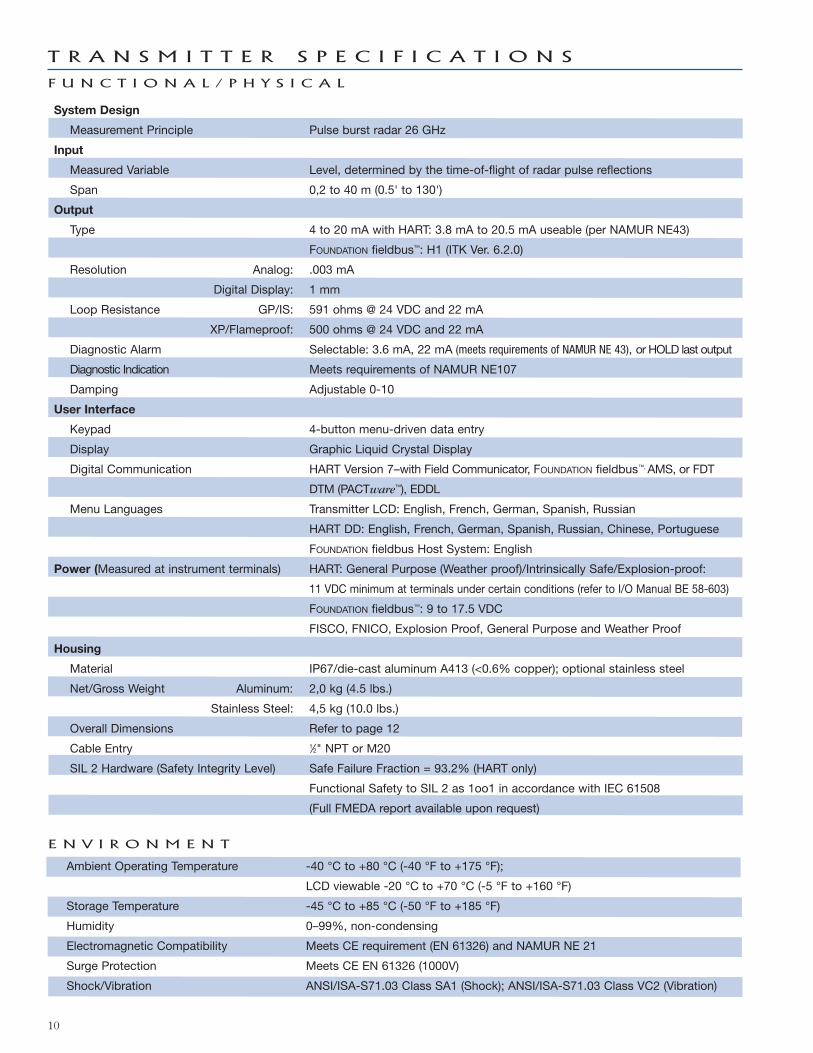
T R A N S M I T T E R S P E C I F I C A T I O N S
F U N C T I O N A L / P H Y S I C A L
10
System Design
Measurement Principle Pulse burst radar 26 GHz
Input
Measured Variable Level, determined by the time-of-flight of radar pulse reflections
Span 0,2 to 40 m (0.5' to 130')
Output
Type 4 to 20 mA with HART: 3.8 mA to 20.5 mA useable (per NAMUR NE43)
FOUNDATION fieldbus™: H1 (ITK Ver. 6.2.0)
Resolution Analog: .003 mA
Digital Display: 1 mm
Loop Resistance GP/IS: 591 ohms @ 24 VDC and 22 mA
XP/Flameproof: 500 ohms @ 24 VDC and 22 mA
Diagnostic Alarm Selectable: 3.6 mA, 22 mA (meets requirements of NAMUR NE 43), or HOLD last output
Diagnostic Indication Meets requirements of NAMUR NE107
Damping Adjustable 0-10
User Interface
Keypad 4-button menu-driven data entry
Display Graphic Liquid Crystal Display
Digital Communication HART Version 7–with Field Communicator, FOUNDATION fieldbus™, AMS, or FDT
DTM (PACTware™), EDDL
Menu Languages Transmitter LCD: English, French, German, Spanish, Russian
HART DD: English, French, German, Spanish, Russian, Chinese, Portuguese
FOUNDATION fieldbus Host System: English
Power (Measured at instrument terminals) HART: General Purpose (Weather proof)/Intrinsically Safe/Explosion-proof:
11 VDC minimum at terminals under certain conditions (refer to I/O Manual BE 58-603)
FOUNDATION fieldbus™: 9 to 17.5 VDC
FISCO, FNICO, Explosion Proof, General Purpose and Weather Proof
Housing
Material IP67/die-cast aluminum A413 (<0.6% copper); optional stainless steel
Net/Gross Weight Aluminum: 2,0 kg (4.5 lbs.)
Stainless Steel: 4,5 kg (10.0 lbs.)
Overall Dimensions Refer to page 12
Cable Entry 1⁄2" NPT or M20
SIL 2 Hardware (Safety Integrity Level) Safe Failure Fraction = 93.2% (HART only)
Functional Safety to SIL 2 as 1oo1 in accordance with IEC 61508
(Full FMEDA report available upon request)
Ambient Operating Temperature -40 °C to +80 °C (-40 °F to +175 °F);
LCD viewable -20 °C to +70 °C (-5 °F to +160 °F)
Storage Temperature -45 °C to +85 °C (-50 °F to +185 °F)
Humidity 0–99%, non-condensing
Electromagnetic Compatibility Meets CE requirement (EN 61326) and NAMUR NE 21
Surge Protection Meets CE EN 61326 (1000V)
Shock/Vibration ANSI/ISA-S71.03 Class SA1 (Shock); ANSI/ISA-S71.03 Class VC2 (Vibration)
E N V I R O N M E N T
Reference Conditions Reflection from ideal reflector at +20 °C (+70 °F)
Linearity ±3 mm (0.1") or 0.1% of tank height (whichever is greater)
Measured Error ±3 mm (0.1") or 0.1% of tank height (whichever is greater)(Performance will degrade slightly within 1.5 m (60") of antenna)
Resolution 1mm or 0.1"
Repeatability ±3 mm (0.1") or 0.05% of tank height (whichever is greater)
Response Time <2 seconds (configuration dependent)
Initialization Time < 30 seconds
Ambient Temperature Effect Digital Average 3 mm (0.12") / 10 K, max of ±10 mm (0.4") over the entiretemperature range -40 °C to +80 °C (-40 °F to +175 °F)
Analog Current Output (additional error with reference to 16 mA span)
Average 0.03 % / 10 K. max 0.45 % over entire temperature range-40 °C to +80 °C (-40 °F to +175 °F)
Maximum Rate of Change 450 cm (180")/minute
FOUNDATION fieldbus™ : ITK Version 6.2.0
H1 Device Class Link Master (LAS)—selectable ON/OFF
H1 Profile Class 31PS, 32L
Function Blocks (8) Al, (3) Transducer, (1) Resource, (2) PID (1) Arithmetic,(1) Signal Characterizer, (1) Input Selector, (1) Integrator
Quiescent Current 17 mA
Execution Time 10 ms (15 ms PID Block)
Device Revision 01
DD Version 0x01
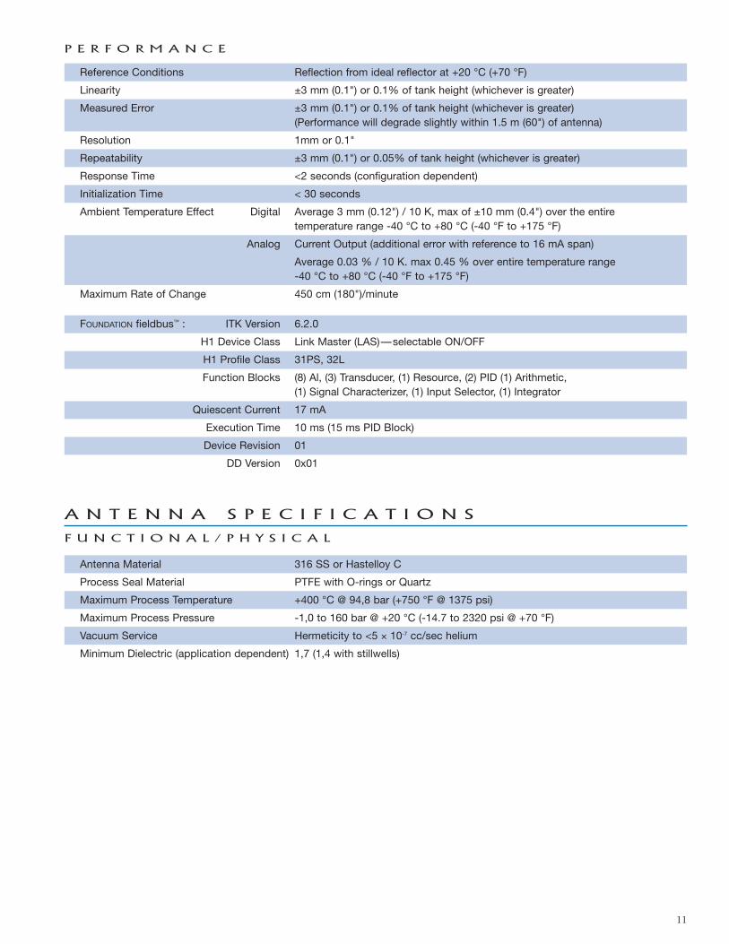
P E R F O R M A N C E
A N T E N N A S P E C I F I C A T I O N S
F U N C T I O N A L / P H Y S I C A L
11
Antenna Material 316 SS or Hastelloy C
Process Seal Material PTFE with O-rings or Quartz
Maximum Process Temperature +400 °C @ 94,8 bar (+750 °F @ 1375 psi)
Maximum Process Pressure -1,0 to 160 bar @ +20 °C (-14.7 to 2320 psi @ +70 °F)
Vacuum Service Hermeticity to <5 × 10⁻⁷ cc/sec helium
Minimum Dielectric (application dependent) 1,7 (1,4 with stillwells)
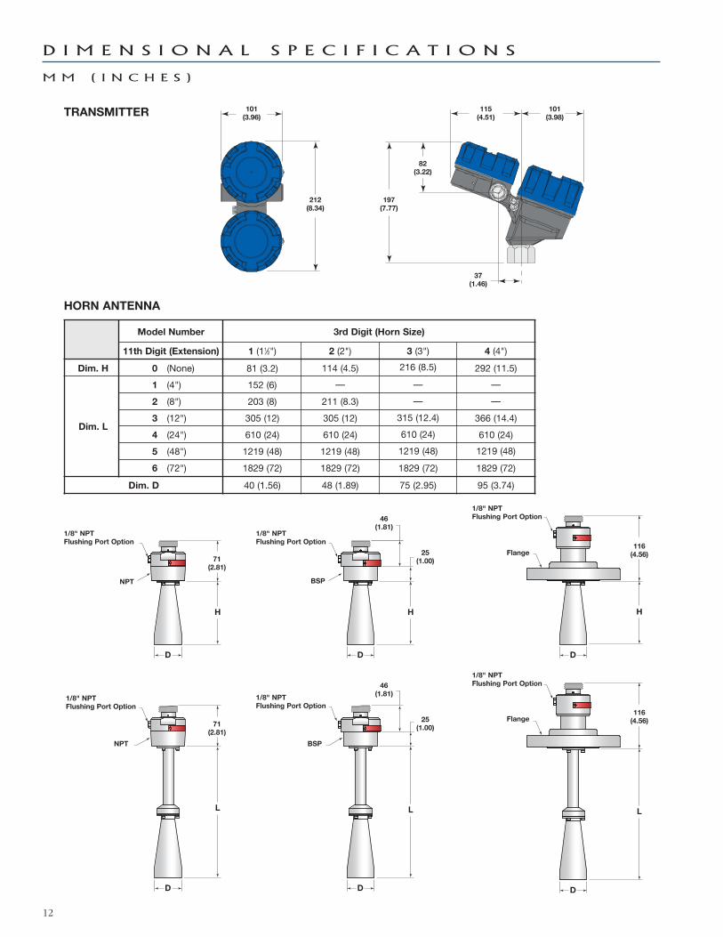
D I M E N S I O N A L S P E C I F I C A T I O N S
M M ( I N C H E S )
12
TRANSMITTER
Model Number 3rd Digit (Horn Size)
11th Digit (Extension) 1 (11⁄2") 2 (2") 3 (3") 4 (4")
Dim. H 0 (None) 81 (3.2) 114 (4.5) 216 (8.5) 292 (11.5)
Dim. L
1 (4") 152 (6) — — —
2 (8") 203 (8) 211 (8.3) — —
3 (12") 305 (12) 305 (12) 315 (12.4) 366 (14.4)
4 (24") 610 (24) 610 (24) 610 (24) 610 (24)
5 (48") 1219 (48) 1219 (48) 1219 (48) 1219 (48)
6 (72") 1829 (72) 1829 (72) 1829 (72) 1829 (72)
Dim. D 40 (1.56) 48 (1.89) 75 (2.95) 95 (3.74)
HORN ANTENNA
D D D
D D D
H
L
H
L
H
L
101(3.96)
1/8" NPTFlushing Port Option
1/8" NPTFlushing Port Option
1/8" NPTFlushing Port Option
1/8" NPTFlushing Port Option
1/8" NPTFlushing Port Option
1/8" NPTFlushing Port Option
NPT
NPT
BSP
Flange
Flange
BSP
71(2.81)
46(1.81)
25(1.00)
116(4.56)
116(4.56)
46(1.81)
25(1.00)
71(2.81)
212(8.34)
115(4.51)
101(3.98)
197(7.77)
82(3.22)
37(1.46)
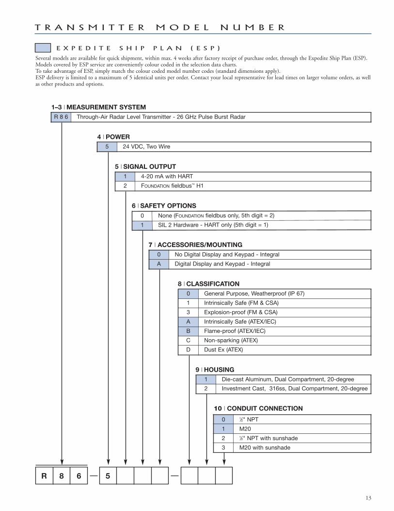
T R A N S M I T T E R M O D E L N U M B E R
13
R 8 6 5
10 | CONDUIT CONNECTION
0 1⁄2" NPT
1 M20
2 1⁄2" NPT with sunshade
3 M20 with sunshade
1–3 | MEASUREMENT SySTEM
R 8 6 Through-Air Radar Level Transmitter - 26 GHz Pulse Burst Radar
4 | POwER
5 24 VDC, Two Wire
5 | SIGNAL OUTPUT
1 4-20 mA with HART
2 FOUNDATION fieldbus™ H1
6 | SAFETy OPTIONS
0 None (FOUNDATION fieldbus only, 5th digit = 2)
1 SIL 2 Hardware - HART only (5th digit = 1)
7 | ACCESSORIES/MOUNTING
0 No Digital Display and Keypad - Integral
A Digital Display and Keypad - Integral
8 | CLASSIFICATION
0 General Purpose, Weatherproof (IP 67)
1 Intrinsically Safe (FM & CSA)
3 Explosion-proof (FM & CSA)
A Intrinsically Safe (ATEX/IEC)
B Flame-proof (ATEX/IEC)
C Non-sparking (ATEX)
D Dust Ex (ATEX)
9 | HOUSING
1 Die-cast Aluminum, Dual Compartment, 20-degree
2 Investment Cast, 316ss, Dual Compartment, 20-degree
Several models are available for quick shipment, within max. 4 weeks after factory receipt of purchase order, through the Expedite Ship Plan (ESP).Models covered by ESP service are conveniently colour coded in the selection data charts.To take advantage of ESP, simply match the colour coded model number codes (standard dimensions apply).ESP delivery is limited to a maximum of 5 identical units per order. Contact your local representative for lead times on larger volume orders, as wellas other products and options.
E X P E D I T E S H I P P L A N ( E S P )
A N T E N N A M O D E L N U M B E R
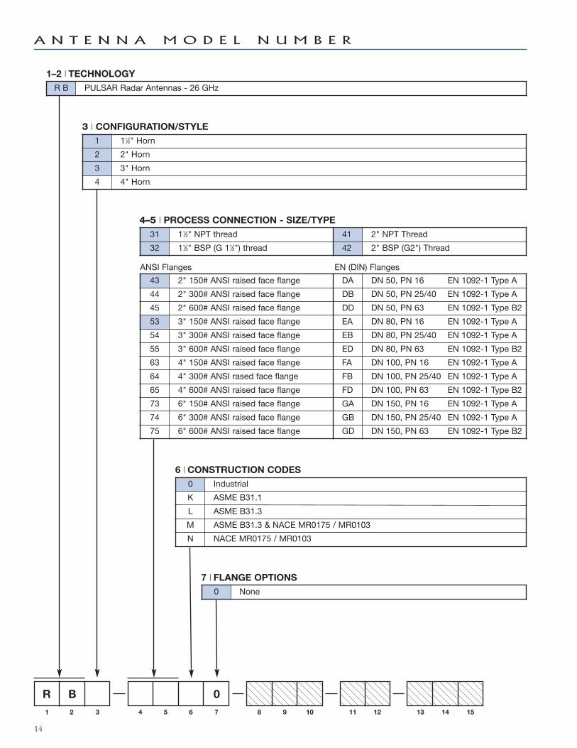
14
3 | CONFIGURATION/STyLE
1 11⁄2" Horn
2 2" Horn
3 3" Horn
4 4" Horn
4–5 | PROCESS CONNECTION - SIZE/TyPE
R B 0
1 2 3 4 5 6 7 8 9 10 11 12 13 14 15
ANSI Flanges EN (DIN) Flanges
1–2 | TECHNOLOGy
R B PULSAR Radar Antennas - 26 GHz
31 11⁄2" NPT thread 41 2" NPT Thread
32 11⁄2" BSP (G 11⁄2") thread 42 2" BSP (G2") Thread
43 2" 150# ANSI raised face flange DA DN 50, PN 16 EN 1092-1 Type A
44 2" 300# ANSI raised face flange DB DN 50, PN 25/40 EN 1092-1 Type A
45 2" 600# ANSI raised face flange DD DN 50, PN 63 EN 1092-1 Type B2
53 3" 150# ANSI raised face flange EA DN 80, PN 16 EN 1092-1 Type A
54 3" 300# ANSI raised face flange EB DN 80, PN 25/40 EN 1092-1 Type A
55 3" 600# ANSI raised face flange ED DN 80, PN 63 EN 1092-1 Type B2
63 4" 150# ANSI raised face flange FA DN 100, PN 16 EN 1092-1 Type A
64 4" 300# ANSI rased face flange FB DN 100, PN 25/40 EN 1092-1 Type A
65 4" 600# ANSI raised face flange FD DN 100, PN 63 EN 1092-1 Type B2
73 6" 150# ANSI raised face flange GA DN 150, PN 16 EN 1092-1 Type A
74 6" 300# ANSI raised face flange GB DN 150, PN 25/40 EN 1092-1 Type A
75 6" 600# ANSI raised face flange GD DN 150, PN 63 EN 1092-1 Type B2
6 | CONSTRUCTION CODES
0 Industrial
K ASME B31.1
L ASME B31.3
M ASME B31.3 & NACE MR0175 / MR0103
N NACE MR0175 / MR0103
7 | FLANGE OPTIONS
0 None
A N T E N N A M O D E L N U M B E R
15
R B 0 0 0 0
1 2 3 4 5 6 7 8 9 10 11 12 13 14 15
A 316SS/316L SS
B Hastelloy C
R 316SS/316L SS with Carbon Steel Flange
S Hastelloy C with Carbon Steel Flange
8 | MATERIAL OF CONSTRUCTION
9 | FUTURE
0
10 | O-RING MATERIALS/SEAL OPTIONS
0 Viton GFLT
2 Kalrez 4079
8 Simriz SZ485 (formerly Aegis PF128) — NACE
A Kalrez 6375
N None - Quartz seal
0 None
1 For nozzle height ≤ 100 mm (4")
2 For nozzle height ≤ 200 mm (8")
3 For nozzle height ≤ 300 mm (12")
4 For nozzle height ≤ 600 mm (24")
5 For nozzle height ≤ 1200 mm (48")
6 For nozzle height ≤ 1800 mm (72")
11 | ANTENNA EXTENSIONS
12 | SPECIAL OPTIONS
0 None
1 1⁄8" NPT Flushing Connection
QUALITY ASSURANCE - ISO 9001:2008THE QUALITY ASSURANCE SYSTEM IN PLACE AT MAGNETROL GUARANTEES THE HIGHEST LEVEL OF QUALITY DURING THE DESIGN,THE CONSTRUCTION AND THE SERVICE OF CONTROLS.OUR QUALITY ASSURANCE SYSTEM IS APPROVED AND CERTIFIED TO ISO 9001:2008 AND OUR TOTAL COMPANY IS COMMITTED TOPROVIDING FULL CUSTOMER SATISFACTION BOTH IN QUALITY PRODUCTS AND QUALITY SERVICE.
PRODUCT WARRANTYALL MAGNETROL ELECTRONIC AND ULTRASONIC LEVEL CONTROLS ARE WARRANTED FREE OF DEFECTS IN MATERIALS AND WORK-
MANSHIP FOR 18 MONTHS FROM THE DATE OF ORIGINAL FACTORY SHIPMENT. IF RETURNED WITHIN THE WARRANTY PERIOD; AND, UPON FACTORY INSPECTION OFTHE CONTROL, THE CAUSE OF THE CLAIM IS DETERMINED TO BE COVERED UNDER THE WARRANTY; THEN, MAGNETROL INTERNATIONAL WILL REPAIR OR REPLACETHE CONTROL AT NO COST TO THE PURCHASER (OR OWNER) OTHER THAN TRANSPORTATION. MAGNETROL SHALL NOT BE LIABLE FOR MISAPPLICATION, LABOR CLAIMS, DIRECT OR CONSEQUENTIAL DAMAGE OR EXPENSE ARISING FROM THE INSTALLATION ORUSE OF THE EQUIPMENT. THERE ARE NO OTHER WARRANTIES EXPRESSED OR IMPLIED, EXCEPT, SPECIAL WRITTEN WARRANTIES COVERING SOME MAGNETROLPRODUCTS.
:2008
BENELUX Heikensstraat 6, 9240 Zele, België -BelgiqueFRANCE Tel. +32 (0)52.45.11.11 • Fax. +32 (0)52.45.09.93 • E-Mail: [email protected] Alte Ziegelei 2-4, D-51491 Overath
Tel. +49 (0)2204 / 9536-0 • Fax. +49 (0)2204 / 9536-53 • E-Mail: [email protected]
ITALIA Via Arese 12, I-20159 MilanoTel. +39 02 607.22.98 • Fax. +39 02 668.66.52 • E-Mail: [email protected]
U.A.E.
RUSSIA Business center “Farvater”, Ruzovskaya Street 8B, office 400A, 190013 St. PetersburgTel. +7 812 320 70 87 • E-Mail: [email protected] Box 261454 • JAFZA LIU FZS1 – BA03, Jebel AliTel. +971 4 880 63 45 • Fax +971 4 880 63 46 • E-Mail: [email protected]
B-506, Sagar Tech Plaza, Saki Naka Junction, Andheri (E), Mumbai - 400072Tel. +91 22 2850 7903 • Fax. +91 22 2850 7904 • E-Mail: [email protected]
UNITED Unit 1 Regent Business Centre, Jubilee Road Burgess Hill West Sussex RH 15 9TLKINGDOM Tel. +44 (0)1444 871313 • Fax +44 (0)1444 871317 • E-Mail: [email protected]
www.magnetrol.com
BULLETIN N°: BE 58-103.0EFFECTIVE: MAY 2017SUPERSEDES: NewUNDER RESERVE OF MODIFICATIONS
OUR NEAREST REPRESENTATIVE