Peroxide Propulsionat
The Turn of the Century
William E. Anderson. NASA MSFC
Kathy Butler, Boeing Rocketdyne Power & Propulsion
Dave Crocket, Orbital Sciences Corp.
Tim Lewis, Orbital Sciences Corporation
Curtis McNeal, NASA MSFC
Introduction
A resurgence of interest in peroxide propulsion has occurred in the last years of the 20 'h
Century. This interest is driven by the need for lower cost propulsion systems and the
need for storable reusable propulsion systems to meet future space transportation system
architectures. NASA and the Air Force are jointly developing two propulsion systems for
flight demonstration early in the 21 s' Century. One system will be a development of
Boeing's AR2-3 engine, which was successfully fielded in the 1960s. The other is a new
pressure-fed design by Orbital Sciences Corporation for expendable mission
requirements. Concurrently NASA and industry are pursuing the key peroxide
technologies needed to design, fabricate, and test advanced peroxide engines to meet the
mission needs beyond 2005. This paper will present a description of the AR2-3, report
the status of its current test program, and describe its intended flight demonstration. This
paper will then describe the Orbital 1OK engine, the status of its test program, and
describe its planned flight demonstration. Finally the paper wiI1 present a plan, or
technology roadmap, for the development of an advanced peroxide engine for the 21 s'
Century.
AR2-3 Engine
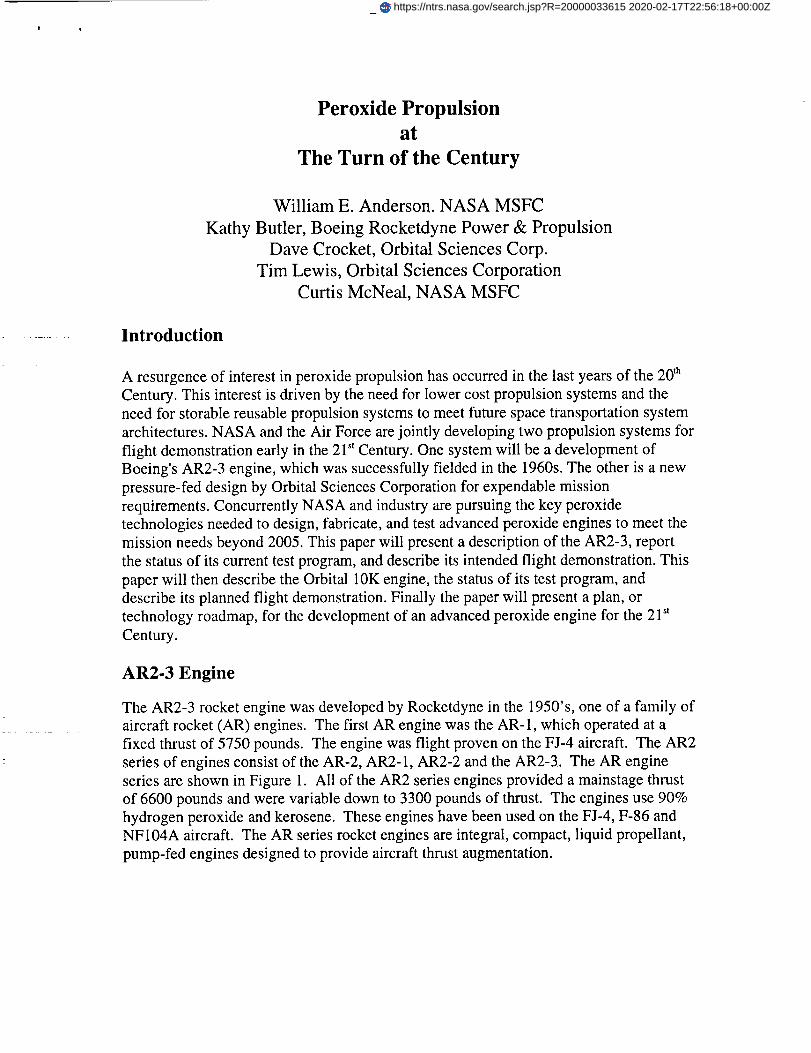
The AR2-3 rocket engine was developed by Rocketdyne in the 1950's, one of a family of
aircraft rocket (AR) engines. The first AR engine was the AR-1, which operated at a
fixed thrust of 5750 pounds. The engine was flight proven on the FJ-4 aircraft. The AR2
series of engines consist of the AR-2, AR2-1, AR2-2 and the AR2-3. The AR engine
series are shown in Figure 1. All of the AR2 series engines provided a mainstage thrust
of 6600 pounds and were variable down to 3300 pounds of thrust. The engines use 90%
hydrogen peroxide and kerosene. These engines have been used on the FJ-4, F-86 and
NF104A aircraft. The AR series rocket engines are integral, compact, liquid propellant,
pump-fed engines designed to provide aircraft thrust augmentation.
https://ntrs.nasa.gov/search.jsp?R=20000033615 2020-02-17T22:56:18+00:00Z
l
Ii
Figure 1. AR-1, AR-2, AR2-1, AR2-2, AR2-3 Rocket Engines.
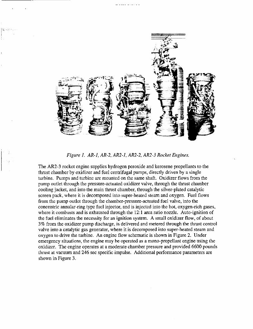
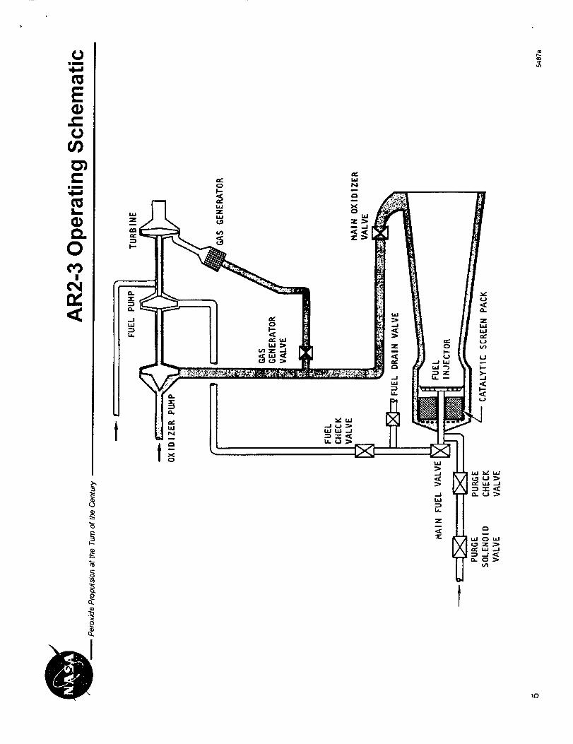
The AR2-3 rocket engine supplies hydrogen peroxide and kerosene propellants to the
thrust chamber by oxidizer and fuel centrifugal pumps, directly driven by a single
turbine. Pumps and turbine are mounted on the same shaft. Oxidizer flows from the
pump outlet through the pressure-actuated oxidizer valve, through the thrust chamber
cooling jacket, and into the main thrust chamber, through the silver-plated catalytic
screen pack, where it is decomposed into super-heated steam and oxygen. Fuel flows
from the pump outlet through the chamber-pressure-actuated fuel valve, into the
concentric annular-ring type fuel injector, and is injected into the hot, oxygen-rich gases,
where it combusts and is exhausted through the 12:1 area ratio nozzle. Auto-ignition of
the fuel eliminates the necessity for an ignition system. A small oxidizer flow, of about
3% from the oxidizer pump discharge, is delivered and metered through the thrust control
valve into a catalytic gas generator, where it is decomposed into super-heated steam and
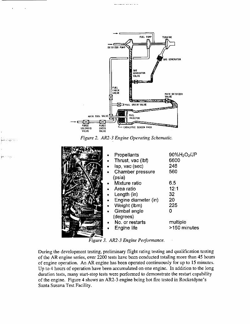
oxygen to drive the turbine. An engine flow schematic is shown in Figure 2. Under
emergency situations, the engine may be operated as a mono-propellant engine using the
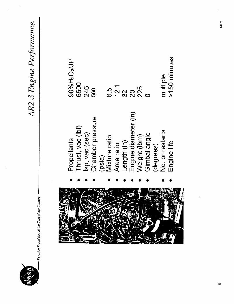
oxidizer. The engine operates at a moderate chamber pressure and provided 6600 pounds
thrust at vacuum and 246 sec specific impulse. Additional performance parameters are
shown in Figure 3.
OXIDIZER
F'UEL PUHP TURBINE
GENERATOR
;AS
GENERATOR
VALVE
FUEL
CHECK
VALVEHAIR OXIDIZERVALVE
ORAIW VALVE
HAIR FUEL VALVEI FUEL
I INJECTOR
PURGE PURGE
SOLENOID CHECK CATALYTIC SCREEN PACK
VALVE VALVE
Figure 2. AR2-3 Engine Operating Schematic.
• Propellants 90%H202/JP• Thrust, vac (Ibf) 6600
• Isp, vac (sec) 246
• Chamber pressure 560
(psia)• Mixture ratio 6.5
• Area ratio 12:1
• Length (in) 32• Engine diameter (in) 20
• Weight (Ibm) 225• Gimbal angle 0
(degrees)• No. or restarts multiple
• Engine life >150 minutes
Figure 3. AR2-3 Engine Performance.
During the development testing, preliminary flight rating testing and qualification testing
of the AR engine series, over 2200 tests have been conducted totaling more than 45 hours
of engine operation. An AR engine has been operated continuously for up to 15 minutes.
Up to 4 hours of operation have been accumulated on one engine. In addition to the long
duration tests, many start-stop tests were performed to demonstrate the restart capability
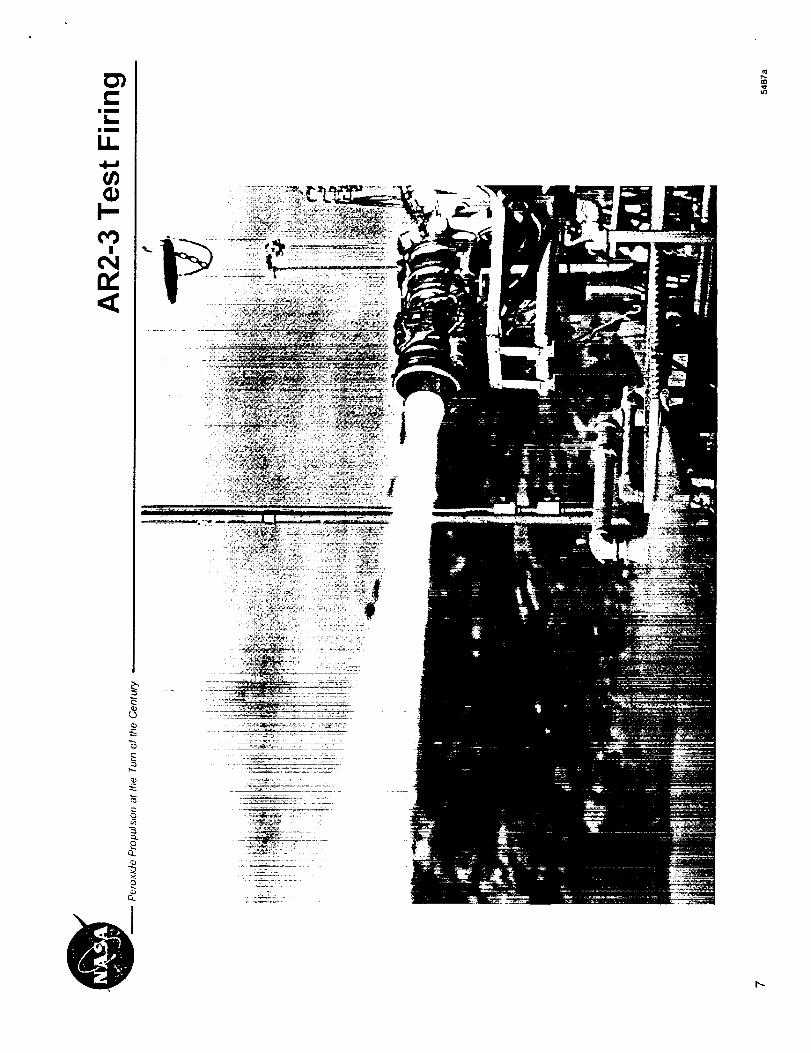
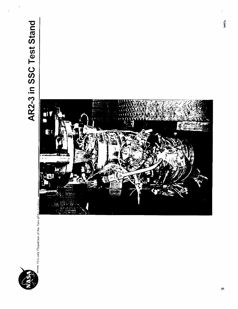
of the engine. Figure 4 shows an AR2-3 engine being hot fire tested in Rocketdyne's
Santa Susana Test Facility.

TheFJ-4aircraftmade103flightswith atotal of 3.5hoursof AR2-3 engine operation. It
had a maximum altitude of 68,000 ft with up to 6 starts per flight. The F-86 aircraft made
31 flights with a total of 1.4 hours of AR2-3 engine operation up to an altitude of 72,000
ft. The NF-104A aircraft made 302 flights with a total of 8.6 hours of AR2-3 engine
operation with a maximum altitude of over 120,000 ft. This aircraft was used as an
astronaut trainer, allowing the trainee to experience a few seconds of weightlessness and
permitting this aircraft to operate in the fringes of space. An NF-104F aircraft is shown
in Figure 5, with the AR2-3 rocket engine firing over Edwards Air Force Base.
Figure 4. AR2-3 Engine Hot Fire Testing. Figure 5. NF-IO4A Aircraft With AR2-3
Firing
AR2-3 Test Results
AR2-3 engine assets were obtained for a hydrogen peroxide propulsion demonstration.
The AR2-3 engine drawings and specifications were pulled from the Rocketdyne vault to
guide the refurbishment effort. The engine components were disassembled and inspected
for wear and damage. A few had never been hot fired. The individual parts were cleaned
and reassembled into the components. The combustion chamber was flow tested with
water. The turbopump was balanced and reassembled. The valves were actuated to
determine the operating characteristics. The relay box was gutted and rewired. The fuel
injector was brought into spec and was water flow tested.
The catalyst packs for the main chamber and the gas generator were disassembled. New
screens were obtained and silver plated. The main chamber screens were packed into the
main catalyst pack housing ready for engine assembly. Screens for two gas generator
catalyst packs were packed, one for the engine and one for gas generator component
testing at the Rocketdyne Santa Susanna Test Facility (SSFL). The gas generator testing
took place over a period of 5 days. Twenty four tests were conducted with 3,192 seconds
of operation and using 230 gallons of 85% hydrogen peroxide. All of the tests were
successful and exhibited very stable operation over a range of operating conditions.
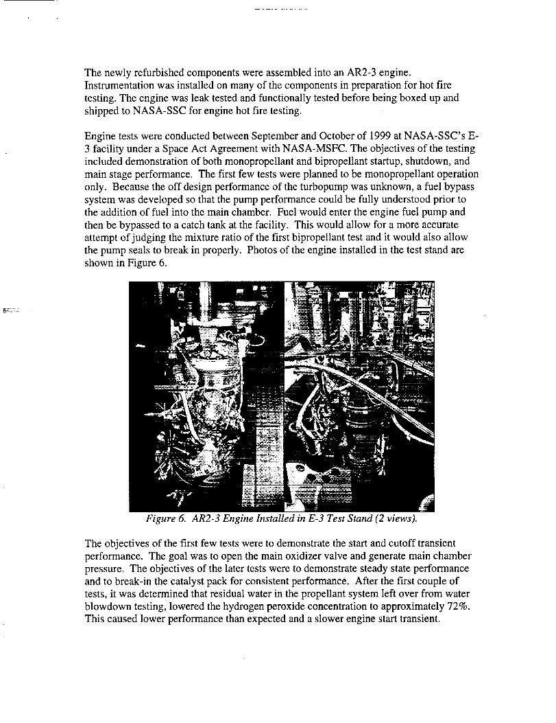
The newlyrefurbishedcomponentswereassembledintoanAR2-3engine.Instrumentationwasinstalledonmanyof thecomponentsin preparationfor hot firetesting.Theenginewasleaktestedandfunctionallytestedbeforebeingboxedupandshippedto NASA-SSCfor enginehot fire testing.
EnginetestswereconductedbetweenSeptemberandOctoberof 1999atNASA-SSC'sE-3 facility underaSpaceAct Agreementwith NASA-MSFC.Theobjectivesof thetestingincludeddemonstrationof bothmonopropellantandbipropellantstartup,shutdown,andmainstageperformance.Thefirst few testswereplannedto bemonopropellantoperationonly. Becausetheoff designperformanceof theturbopumpwasunknown,a fuelbypasssystemwasdevelopedsothatthepumpperformancecouldbefully understoodprior totheadditionof fuel into themainchamber.Fuelwouldentertheenginefuel pumpandthenbebypassedto acatchtankatthefacility. Thiswouldallow for amoreaccurateattemptof judging themixtureratioof thefirst bipropellanttestandit would alsoallowthepumpsealsto breakin properly. Photosof theengineinstalledin theteststandareshownin Figure6.
Figure 6. AR2-3 Engine Installed in E-3 Test Stand (2 views).
The objectives of the first few tests were to demonstrate the start and cutoff transient
performance. The goal was to open the main oxidizer valve and generate main chamber
pressure. The objectives of the later tests were to demonstrate steady state performance
and to break-in the catalyst pack for consistent performance. After the first couple of
tests, it was determined that residual water in the propellant system left over from water
blowdown testing, lowered the hydrogen peroxide concentration to approximately 72%.
This caused lower performance than expected and a slower engine start transient.
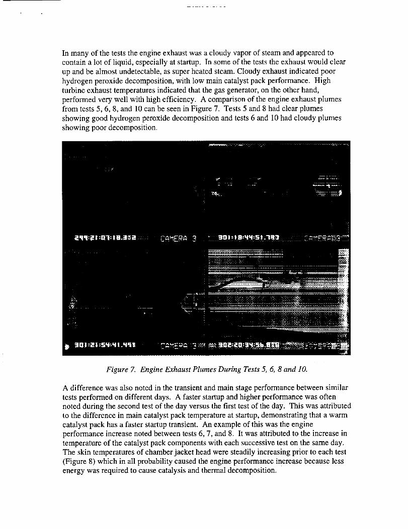
In manyof theteststheengineexhaustwasacloudyvaporof steamandappearedtocontaina lot of liquid, especiallyatstartup.In someof theteststheexhaustwouldclearup andbealmostundetectable,assuperheatedsteam.Cloudyexhaustindicatedpoorhydrogenperoxidedecomposition,with low maincatalystpackperformance.Highturbineexhausttemperaturesindicatedthatthegasgenerator,on theotherhand,performedverywell with highefficiency. A comparisonof theengineexhaustplumesfrom tests5, 6, 8, and 10canbeseeninFigure7. Tests5 and8hadclearplumesshowinggoodhydrogenperoxidedecompositionandtests6 and 10hadcloudyplumesshowingpoordecomposition.
Figure 7. Engine Exhaust Plumes During Tests 5, 6, 8 and 10.
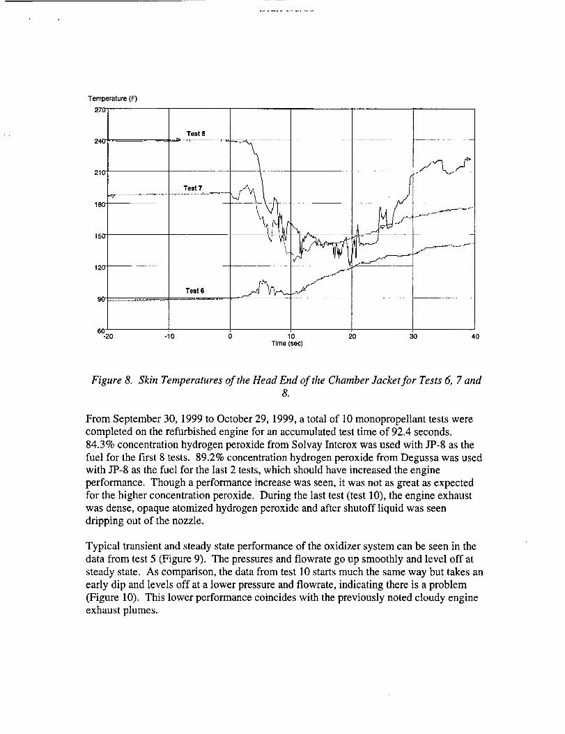
A difference was also noted in the transient and main stage performance between similar
tests performed on different days. A faster startup and higher performance was often
noted during the second test of the day versus the first test of the day. This was attributed
to the difference in main catalyst pack temperature at startup, demonstrating that a warm
catalyst pack has a faster startup transient. An example of this was the engine
performance increase noted between tests 6, 7, and 8. It was attributed to the increase in
temperature of the catalyst pack components with each successive test on the same day.
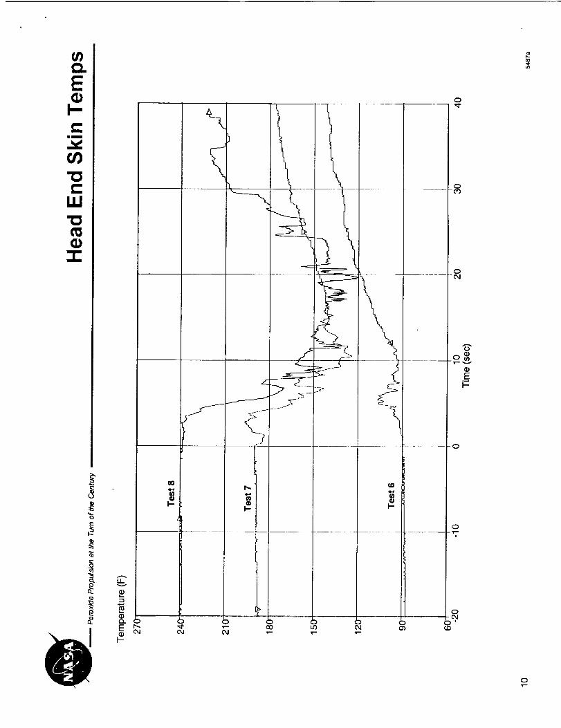
The skin temperatures of chamber jacket head were steadily increasing prior to each test
(Figure 8) which in all probability caused the engine performance increase because less
energy was required to cause catalysis and thermal decomposition.
Temperature (F)
Test 8
_' ........... -_........,.-_ Test 7
_~_
Test 6
-20 -10 0 10 20 30Time(sec)
40
Figure 8. Skin Temperatures of the Head End of the Chamber Jacket for Tests 6, 7 and8.
From September 30, 1999 to October 29, 1999, a total of 10 monopropellant tests were
completed on the refurbished engine for an accumulated test time of 92.4 seconds.
84.3% concentration hydrogen peroxide from Solvay Interox was used with JP-8 as the
fuel for the first 8 tests. 89.2% concentration hydrogen peroxide from Degussa was used
with JP-8 as the fuel for the last 2 tests, which should have increased the engine
performance. Though a performance increase was seen, it was not as great as expected
for the higher concentration peroxide. During the last test (test 10), the engine exhaust
was dense, opaque atomized hydrogen peroxide and after shutoff liquid was seen
dripping out of the nozzle.
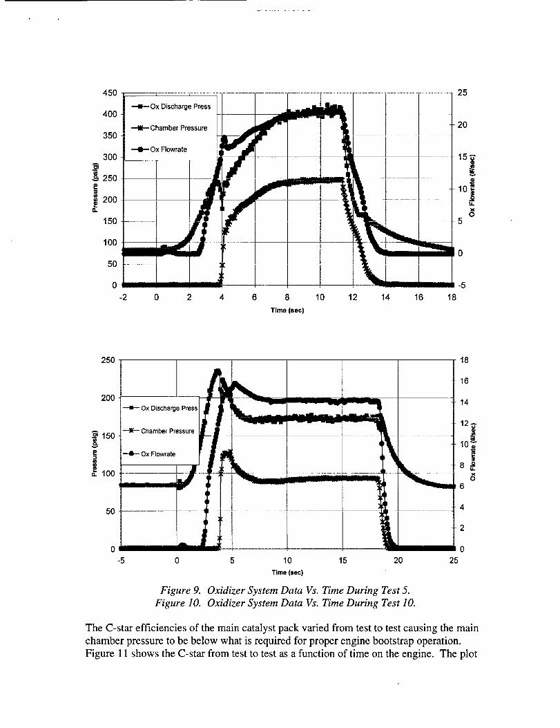
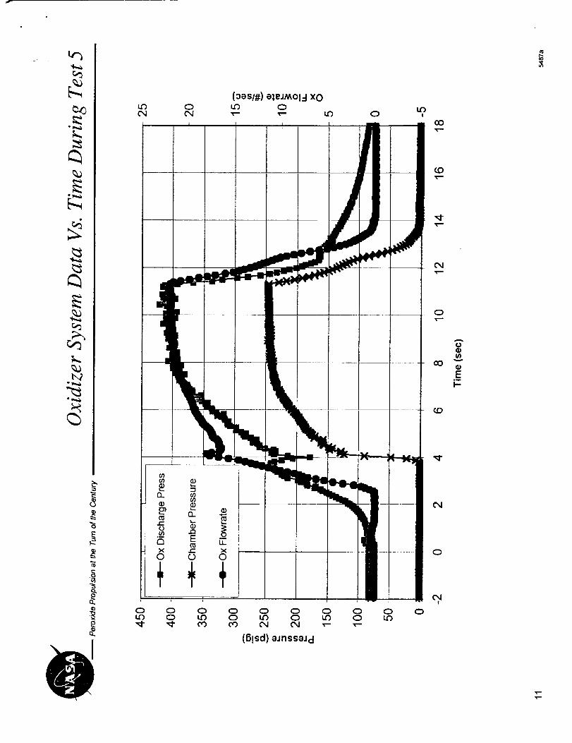
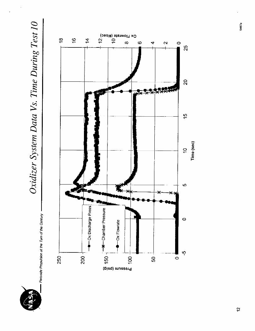
Typical transient and steady state performance of the oxidizer system can be seen in the
data from test 5 (Figure 9). The pressures and flowrate go up smoothly and level off at
steady state. As comparison, the data from test 10 starts much the same way but takes an
early dip and levels off at a lower pressure and flowrate, indicating there is a problem
(Figure 10). This lower performance coincides with the previously noted cloudy engine
exhaust plumes.
45O
4OO
35O
300
250
200a.
150
IO0
5O
0
-2
i i
Ox Discharge Press
Chamber Pressure
+ Ox Flowrate
!
iJ
i A
III I
!
I
t • .... _.... L.m
i
1 _____
' ii
2 4 6 8 10
Time (see)
12 14 16
25
2O
o14.
05
-5
18
250
200
150v
i 100
5O
0
-5 0 5 10 15
Time(sec)
Figure 9.
Figure lO.
!
k2O
Oxidizer System Data Vs. Time During Test 5.
Oxidizer System Data Vs. Time During Test 10.
18
16
14
12
6
4
2
0
25
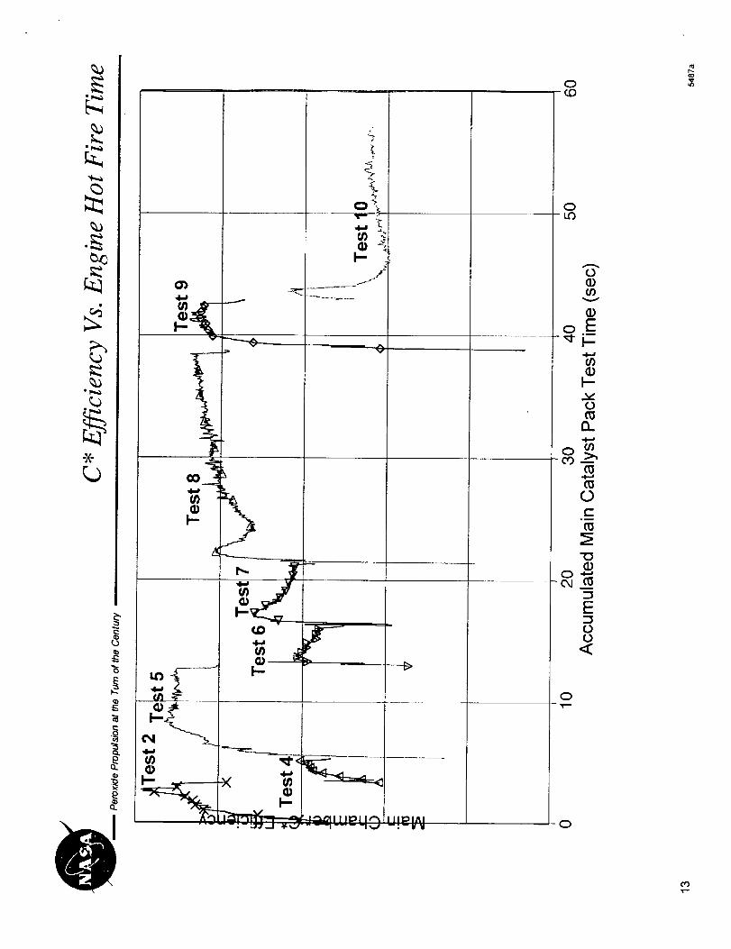
The C-star efficiencies of the main catalyst pack varied from test to test causing the main
chamber pressure to be below what is required for proper engine bootstrap operation.
Figure 11 shows the C-star from test to test as a function of time on the engine. The plot
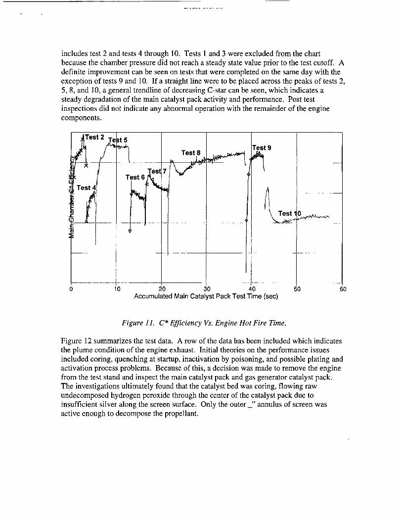
includes test 2 and tests 4 through 10. Tests 1 and 3 were excluded from the chart
because the chamber pressure did not reach a steady state value prior to the test cutoff. A
definite improvement can be seen on tests that were completed on the same day with the
exception of tests 9 and 10. If a straight line were to be placed across the peaks of tests 2,
5, 8, and 10, a general trendline of decreasing C-star can be seen, which indicates a
steady degradation of the main catalyst pack activity and performance. Post test
inspections did not indicate any abnormal operation with the remainder of the engine
components.
Test 6
Test 9
0 20 30 40 50Accumulated Main Catalyst Pack Test Time (sec)
6O
Figure 11. C* Efficiency Vs. Engine Hot Fire Time.
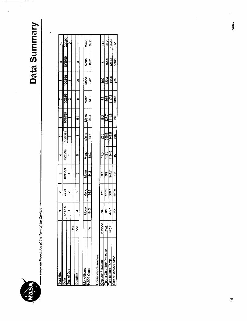
Figure 12 summarizes the test data. A row of the data has been included which indicates
the plume condition of the engine exhaust. Initial theories on the performance issues
included coring, quenching at startup, inactivation by poisoning, and possible plating and
activation process problems. Because of this, a decision was made to remove the engine
from the test stand and inspect the main catalyst pack and gas generator catalyst pack.
The investigations ultimately found that the catalyst bed was coring, flowing raw
undecomposed hydrogen peroxide through the center of the catalyst pack due to
insufficient silver along the screen surface. Only the outer _" annulus of screen was
active enough to decompose the propellant.
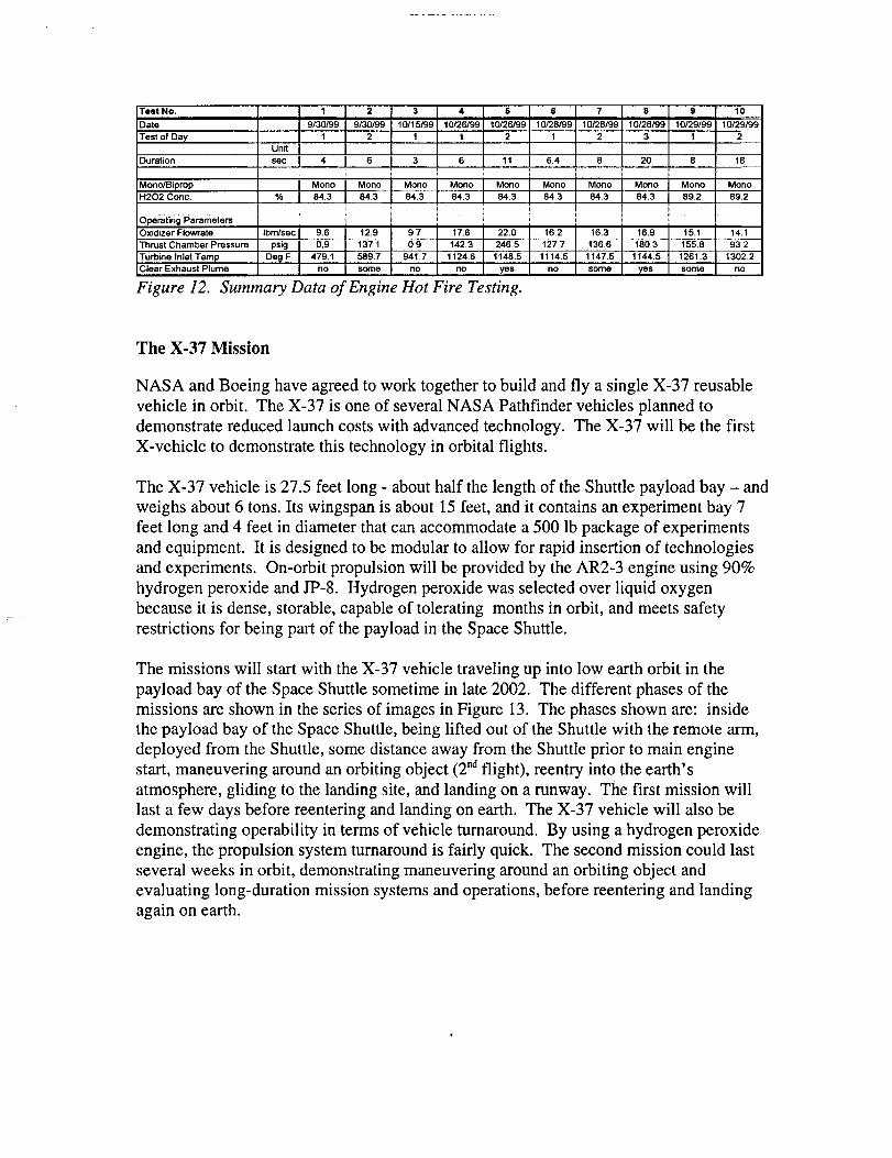
Test No.
Date
Test of Day
Duration
Mono/BipropH202 Conc.
1 2
9/30199 9/30199
1 2Unit
set: 4 6
Mono I Mono% 84.3 84.3
3 4 5 6 7 8 9 10
10/15/99 10126/99 10126/99 10/28/99 10128/99 10/28/99 10/29199 --i'0/29/99
1 1 2 1 2 3 1 2
3 6 11 6.4 6 20 6 18
Mono I Mono Mono Mono I Mono Mono Mono Mono64.3 64.3 84.3 84.3 84.3 64,3 89.2 69.2
0perating Parameters ..........................................................................................._..........................................................................................................................'........................................
Oxidizer Flowrate Ibm/sec 9.6 12.9 9.7 17.6 22.0 16.2 16.3 16.9 15.1 14.1
Thrust Chamber Pressure psig 0.9 137.1 0.9 142.3 246.5 127.7 136.6 160.3 155.8 93.2
Turbine Inlet Temp De_l F. 479.1 589.7 941.7 1124.6 1148,6 1114,5 1147.5 1144.5 1261,3 1302.2Clear Exhaust Plume no some no no yes no some yes some no
Figure 12. Summary Data of Engine Hot Fire Testing.
The X-37 Mission
NASA and Boeing have agreed to work together to build and fly a single X-37 reusable
vehicle in orbit. The X-37 is one of several NASA Pathfinder vehicles planned to
demonstrate reduced launch costs with advanced technology. The X-37 will be the first
X-vehicle to demonstrate this technology in orbital flights.
The X-37 vehicle is 27.5 feet long - about half the length of the Shuttle payload bay - and
weighs about 6 tons. Its wingspan is about 15 feet, and it contains an experiment bay 7
feet long and 4 feet in diameter that can accommodate a 500 lb package of experiments
and equipment. It is designed to be modular to allow for rapid insertion of technologies
and experiments. On-orbit propulsion will be provided by the AR2-3 engine using 90%
hydrogen peroxide and JP-8. Hydrogen peroxide was selected over liquid oxygen
because it is dense, storable, capable of tolerating months in orbit, and meets safety
restrictions for being part of the payload in the Space Shuttle.
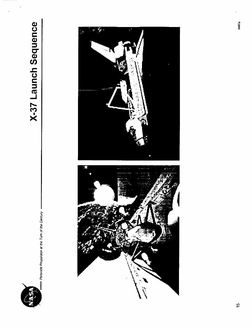
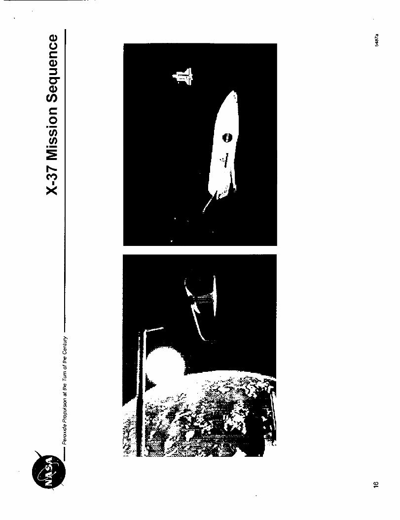
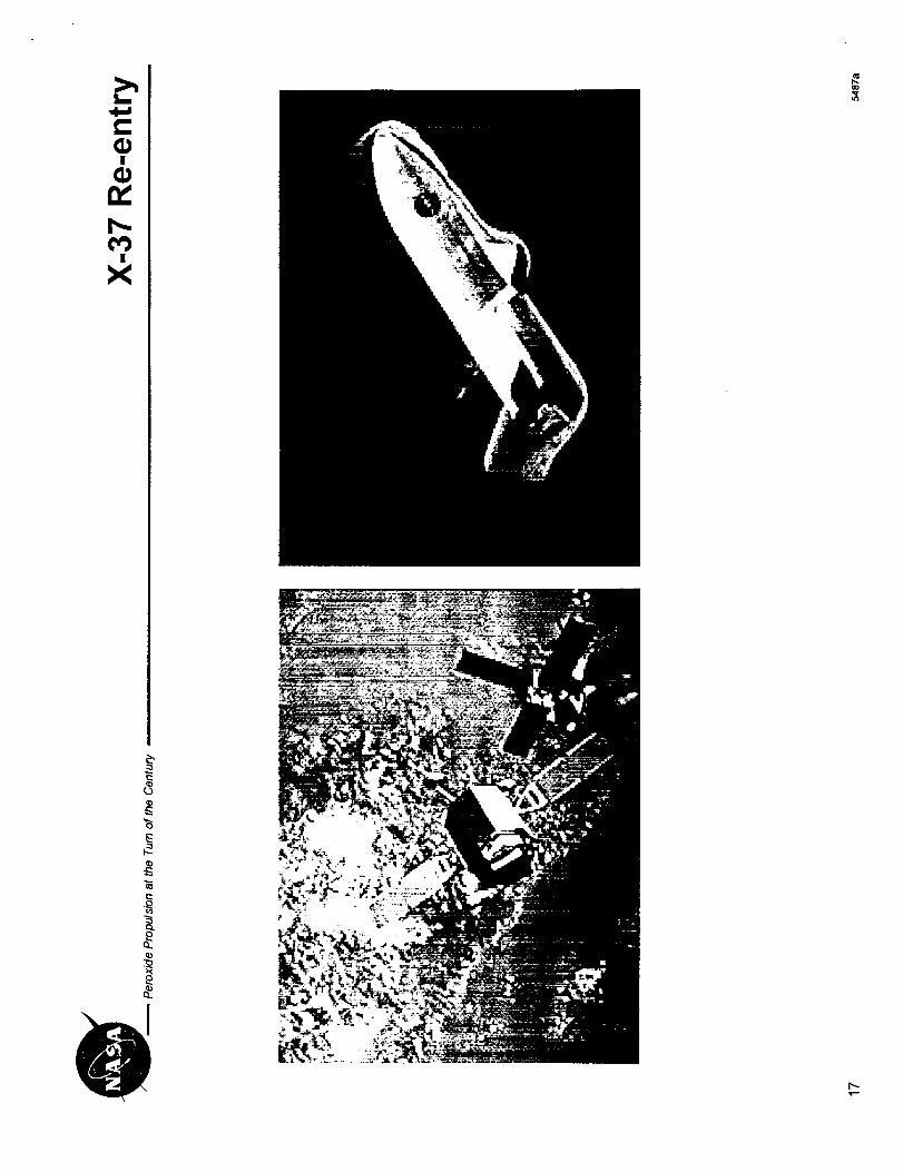
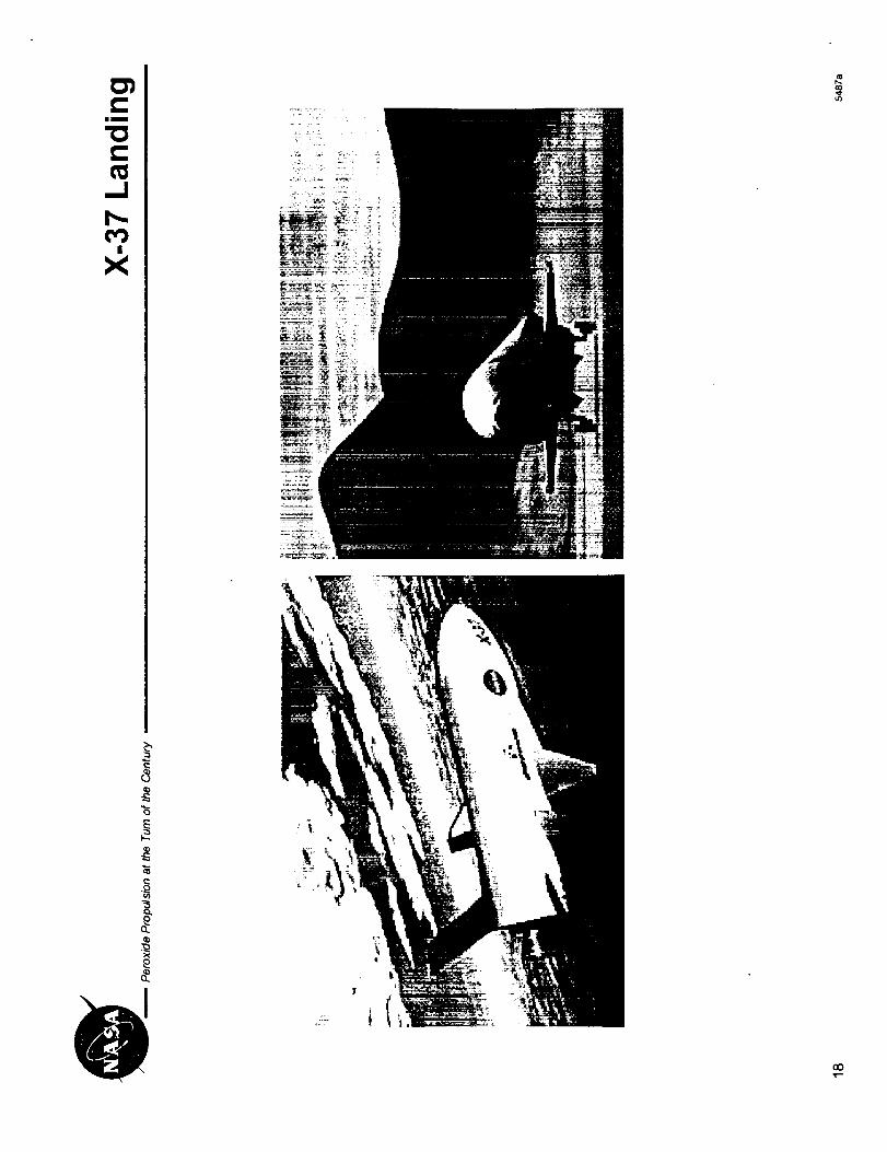
The missions will start with the X-37 vehicle traveling up into low earth orbit in the
payload bay of the Space Shuttle sometime in late 2002. The different phases of the
missions are shown in the series of images in Figure 13. The phases shown are: inside
the payload bay of the Space Shuttle, being lifted out of the Shuttle with the remote arm,
deployed from the Shuttle, some distance away from the Shuttle prior to main engine
start, maneuvering around an orbiting object (2 "d flight), reentry into the earth's
atmosphere, gliding to the landing site, and landing on a runway. The first mission will
last a few days before reentering and landing on earth. The X-37 vehicle will also be
demonstrating operability in terms of vehicle turnaround. By using a hydrogen peroxide
engine, the propulsion system turnaround is fairly quick. The second mission could last
several weeks in orbit, demonstrating maneuvering around an orbiting object and
evaluating long-duration mission systems and operations, before reentering and landing
again on earth.
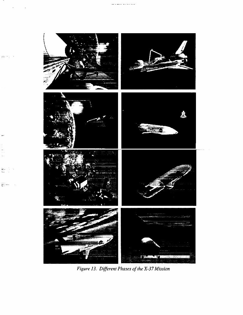
\
Figure 13. Different Phases of the X-37 Mission
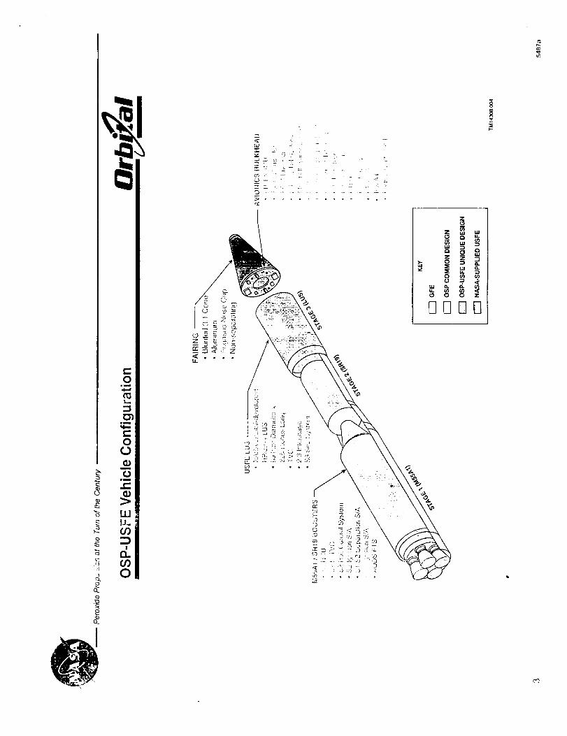
The USFE 10k Engine
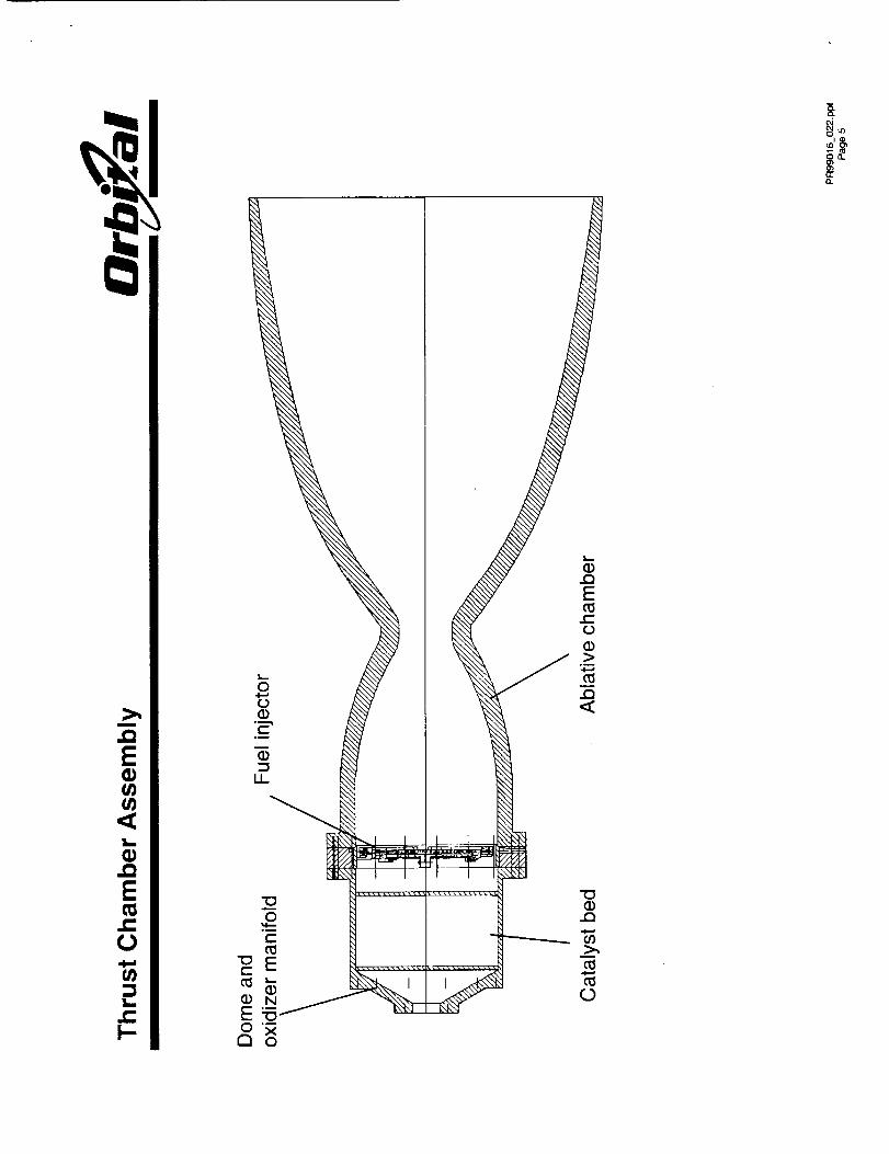
The engine consists of pneumatically-actuated ball valves, propellant feed-lines, the
oxidizer dome with a mount for gimbal attachments, a catalyst bed to convert the HTP
into oxygen and superheated steam, a fuel injector, and an ablative chamber and nozzle.
Low material and design costs coupled with robust margins were the guiding philosophy
toward selecting a design.
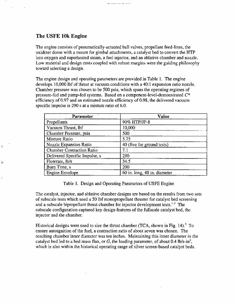
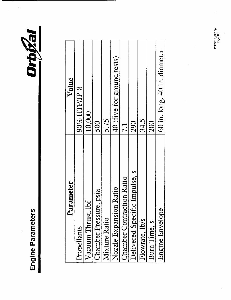
The engine design and operating parameters are provided in Table 1. The engine
develops 10,000 lbf of thrust at vacuum conditions with a 40:1 expansion ratio nozzle.
Chamber pressure was chosen to be 500 psia, which spans the operating regimes of
pressure-fed and pump-fed systems. Based on a component-level-demonstrated C*
efficiency of 0.97 and an estimated nozzle efficiency of 0.98, the delivered vacuum
specific impulse is 290 s at a mixture ratio of 6.0.
Parameter .... Value
Propellants 90% HTP/JP-8
Vacuum Thrust, lbf 10,000
Chamber Pressure, psiaMixture Ratio
Nozzle Expansion RatioChamber Contraction Ratio
Delivered Specific Impulse, s
Flowrate, lb/s
500
5.75
4 0 (five,for ground tests)7.1
290
34.5
Burn Time, s 200
Engine Envelope 60 in. long, 40 in. diameter
Table 1. Design and Operating Parameters of USFE Engine
The catalyst, injector, and ablative chamber designs are based on the results from two sets
of subscale tests which used a 50 lbf monopropellant thruster for catalyst bed screening
and a subscale bipropellant thrust chamber for injector development testsJ' 2 The
subscale configuration captured key design features of the fullscale catalyst bed, the
injector and the chamber.
Historical designs were used to size the thrust chamber (TCA, shown in Fig. 14). 3 To
ensure autoignition of the fuel, a contraction ratio of about seven was chosen. The
resulting chamber inner diameter was ten inches. Maintaining this inner diameter in the
catalyst bed led to a bed mass flux, or G, the loading parameter, of about 0.4 lb/s-in 2,
which is also within the historical operating range of silver screen-based catalyst beds.
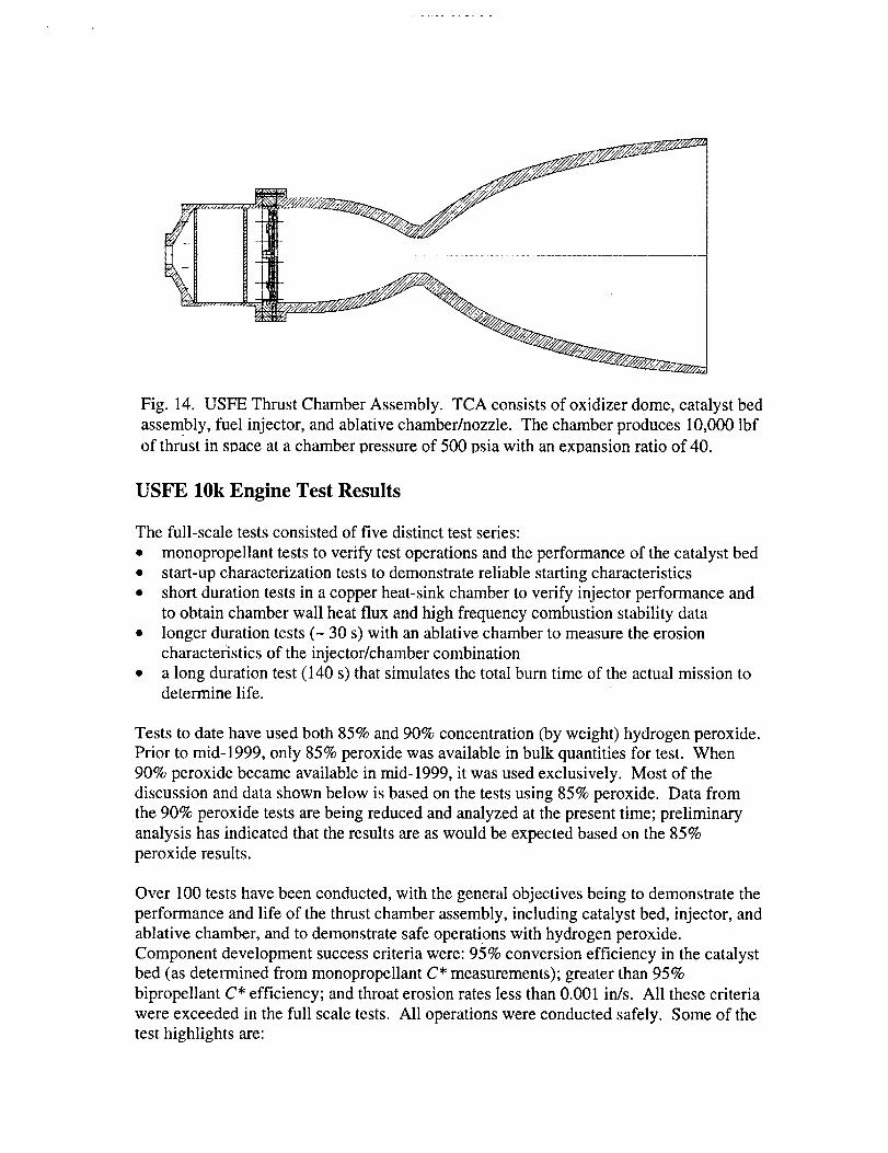
Fig. 14. USFEThrustChamberAssembly.TCA consistsof oxidizer dome, catalyst bed
assembly, fuel injector, and ablative chamber/nozzle. The chamber produces 10,000 lbf
of thrust in soace at a chamber oressure of 500 osia with an exoansion ratio of 40.
USFE 10k Engine Test Results
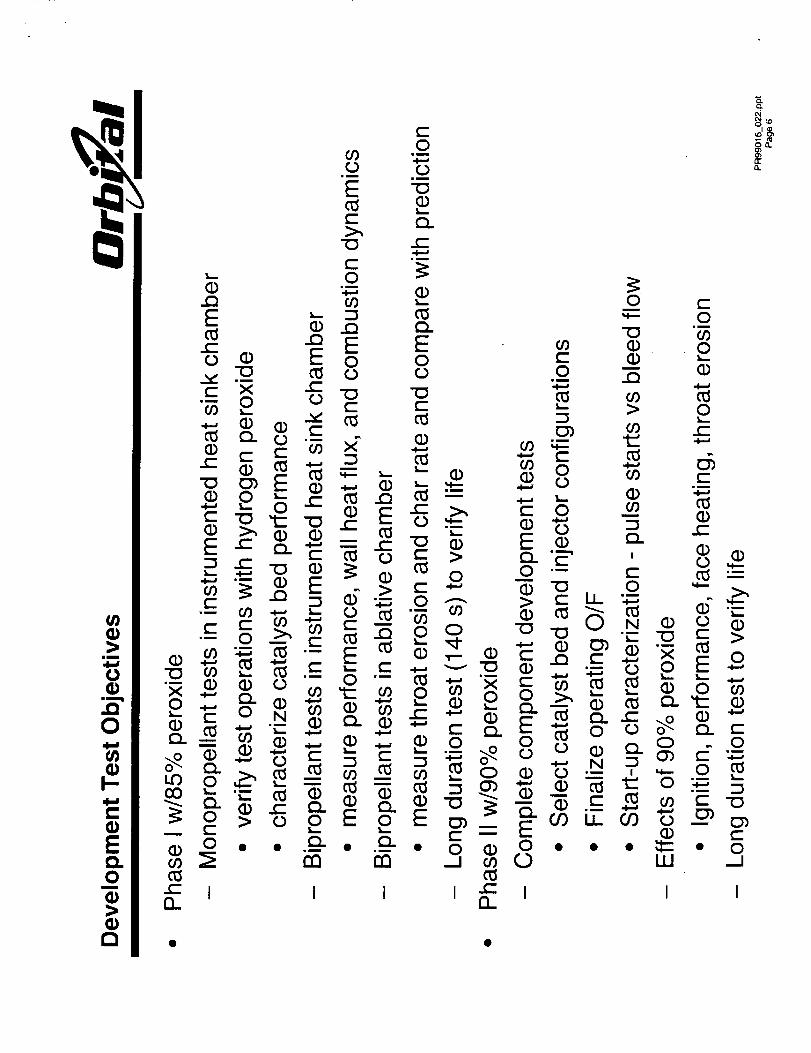
The full-scale tests consisted of five distinct test series:
• monopropellant tests to verify test operations and the performance of the catalyst bed
• start-up characterization tests to demonstrate reliable starting characteristics
• short duration tests in a copper heat-sink chamber to verify injector performance and
to obtain chamber wail heat flux and high frequency combustion stability data
• longer duration tests (- 30 s) with an ablative chamber to measure the erosion
characteristics of the injector/chamber combination
• a long duration test (140 s) that simulates the total burn time of the actual mission todetermine life.
Tests to date have used both 85% and 90% concentration (by weight) hydrogen peroxide.
Prior to mid-1999, only 85% peroxide was available in bulk quantities for test. When
90% peroxide became available in mid-1999, it was used exclusively. Most of the
discussion and data shown below is based on the tests using 85% peroxide. Data from
the 90% peroxide tests are being reduced and analyzed at the present time; preliminary
analysis has indicated that the results are as would be expected based on the 85%
peroxide results.
Over 100 tests have been conducted, with the general objectives being to demonstrate the
performance and life of the thrust chamber assembly, including catalyst bed, injector, and
ablative chamber, and to demonstrate safe operations with hydrogen peroxide.
Component development success criteria were: 95% conversion efficiency in the catalyst
bed (as determined from monopropellant C* measurements); greater than 95%
bipropellant C* efficiency; and throat erosion rates less than 0.001 in/s. All these criteria
were exceeded in the full scale tests. All operations were conducted safely. Some of the
test highlights are:
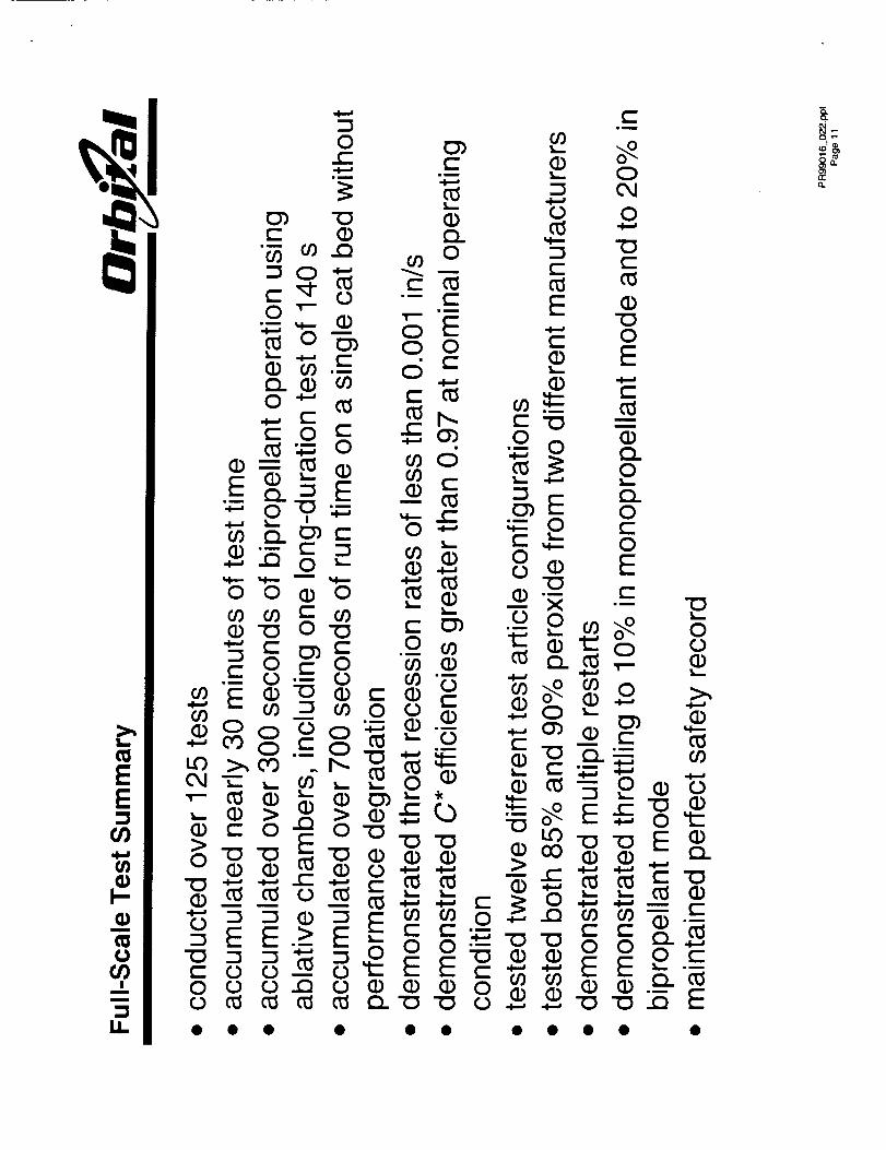
• conducted over 125 tests
• accumulated nearly 30 minutes of test time
• accumulated over 300 seconds of bipropellant operation using ablative chambers,
including one long-duration test of 140 s
• accumulated over 700 seconds of run time on a single cat bed without performance
degradation• demonstrated throat recession rates of less than 0.001 in/s
• demonstrated C* efficiencies greater than 0.97 at nominal operating condition
• tested twelve different test article configurations
• tested both 85% and 90% peroxide from two different manufacturers
• demonstrated multiple restarts
• demonstrated throttling to 10% in monopropellant mode and to 20% in bipropellantmode
• maintained perfect safety record
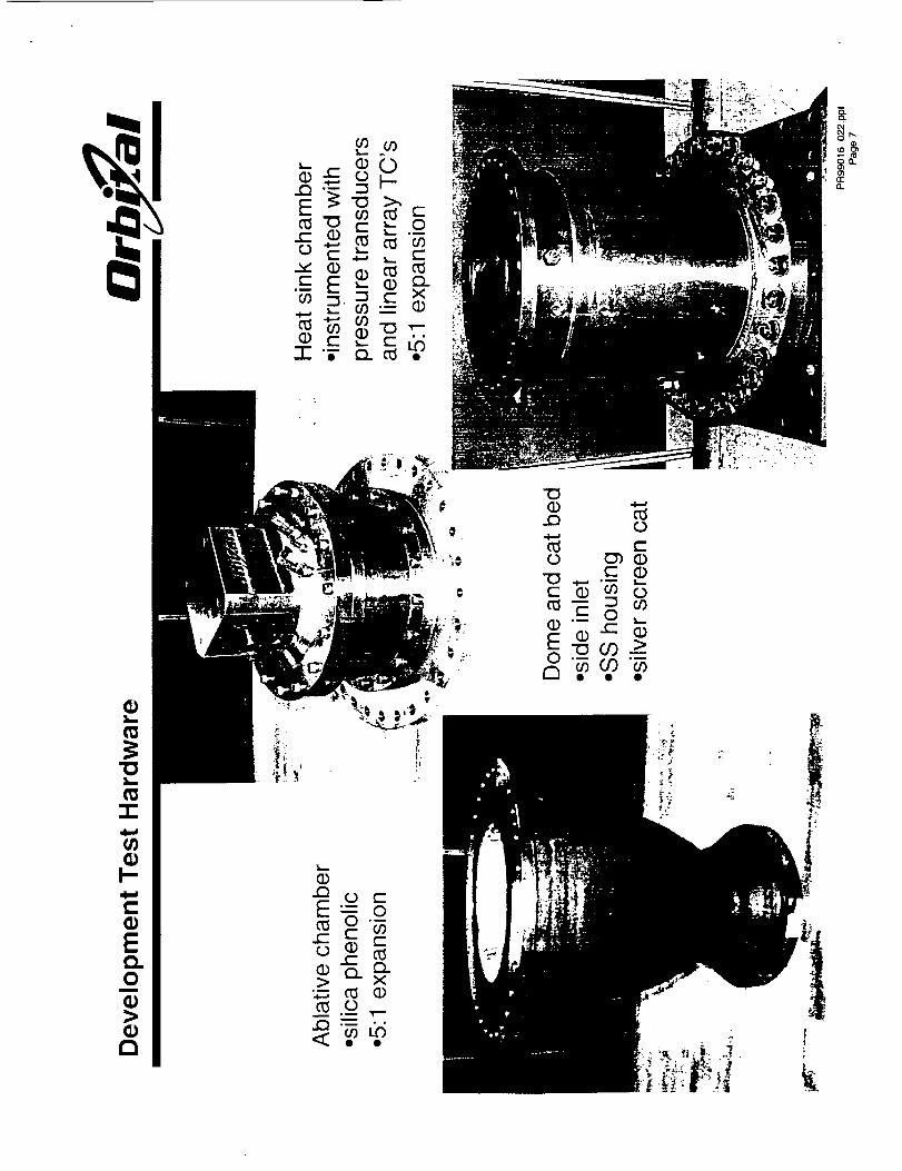
The demonstration test TCA was designed in a bolted-together arrangement to allow for
rapid component replacement. The TCA consisted of four distinct subcomponents: a
workhorse oxidizer dome with a side inlet which served as a test facility interface; a
catalyst bed assembly, including a structural housing and a slip-in catalyst bed to allow
different cat bed designs to be tested; a fuel manifold (another test facility interface) and
injector; and the chamber/nozzle.
Two basic chamber/nozzle configurations were tested - a copper heat sink chamber and
an ablative chamber. The heat sink chamber was well-instrumented for making pressure
and temperature measurements. Static pressure measurements were made in four axial
locations - between the cat bed exit and the injector, downstream of the injector face, at
the entrance to the converging part of the chamber, and in the chamber throat. A water-
cooled high-speed pressure transducer was placed one inch downstream of the injector
face. Linear array thermocouples were inserted into the chamber to measure heat flux at
four different locations. The heat flux measurements in conjunction with the NAT 4 and
CMA 5 codes were used to determine the near wall gas temperature. The near wall gas
temperature was used to determine the operating O/F that would result in an acceptableamount of throat erosion in the ablative chamber.
The catalyst beds tested were essentially of the silver screen type. Both pure silver and
silver-plated nickel screen catalysts were tested. Both uncoated and coated screens were
tested. The best configuration tested was made of pure silver screens with a samarium
nitrate coating. The bed length was two inches. The nominal bed loading was 0.4 lb/s-
in 2, and values up to 0.7 were tested with 85% peroxide. At this high value of G, high
decomposition temperatures were measured, but the exhaust plume observed by remote
cameras was not transparent like it was for the nominal case.
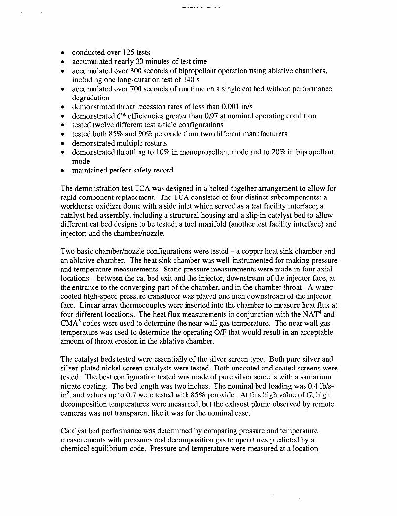
Catalyst bed performance was determined by comparing pressure and temperature
measurements with pressures and decomposition gas temperatures predicted by a
chemical equilibrium code. Pressure and temperature were measured at a location
betweenthecatbedexit andtheinjectorentrance.Whenevertheexhaustplumewasclear,themeasurementsindicatedessentially100%decomposition.
b
1
0.99
0.98
0.97
0.96
0.95
0.94
0.93
0.92
o.91
0.9
4 5 6 7 8
O/F
• inj #1; Cu chmbr
• inj #2; Cu chmbr
e inj #1; abl chmbr
inj #2; abl chmbr
Fig. 15. C* efficiency as function of O/F in heat sink (Cu)
and ablative (abl) chambers. Injector # 1 is "steam port"
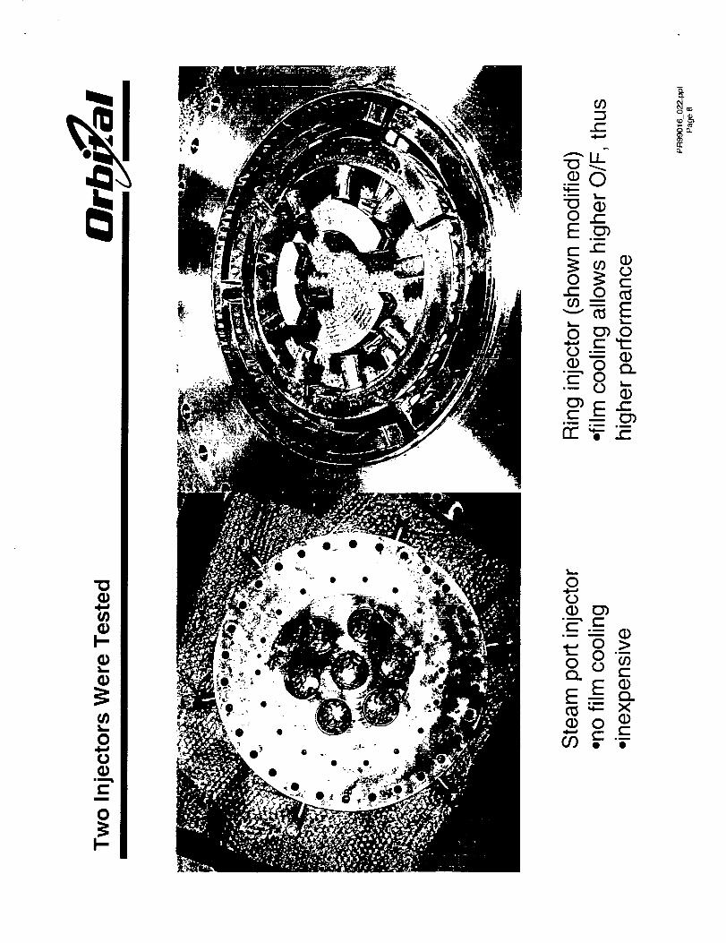
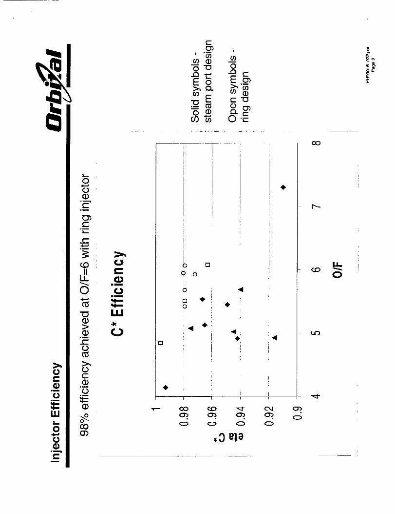
Two types of injectorswere tested - a "steam
port" design, similar tothat used in the Gamma
engines, and the other a
ring-type injector. A
third type of steam port
injector has been
fabricated and tested,with the data reduction
ongoing at the present
time. The ring injector
used O/F biasing to
provide a fuel-rich gasaround the chamber
periphery, and near
stoichiometric conditions
in the core. This injectorhas been tested with both
85% and 90% peroxide. Injector performance was determined from chamber pressure
measurements and comparison with theoretical C* values. The pressure loss across the
injector was also measured. Both injectors achieved C* efficiencies greater than 95% at
their nominal operating conditions (Fig. 15). A higher operating O/F was possible with
the ring injector because the fuel-rich periphery provided for minimal throat erosion.
The ablative chamber/nozzle consists of a silica phenolic liner and an epoxy-glass
phenolic overwrap. For sea-level tests, the 40:1 nozzle is cut at a 5:1 ratio, providing a
nearly ideal expansion to atmospheric conditions. The ablative chamber was
instrumented with thermocouples and strain gages.
The throat erosion was measured after each test with calipers. The rate of erosion was
determined to be a function of operating O_ and the injector that was used in the test.
The gas temperature and chamber pressure are the primary parameters that determine the
erosion rate of the silica phenolic. Silica is non-reactive with the combustion gas, thus
there is no thermochemical erosion in this engine configuration. Mechanical (silica melt
flow) erosion is the primary mechanism driving the material loss in the throat of thenozzle.
6000
5000
- 4000
3000
2000E
looo
0
4 5 6 7 8
O/F
• injector# 1
• injector # 2
-- equilibrium
gas temp
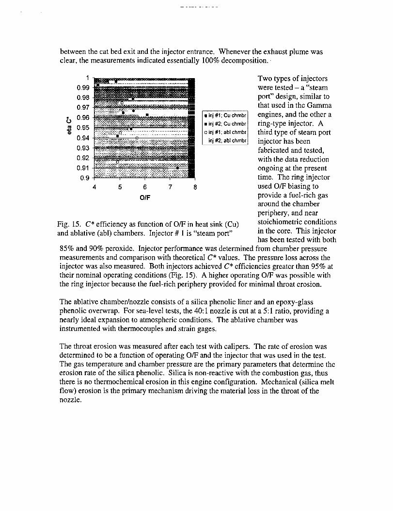
Fig. 16. Effective (near wall) gas temperature as function
of O/F for each injector. Equilibrium bulk gas temperature
is shown for comparison. Injector # 1 is "steam port"de,_ien and iniector #2 is fine design.
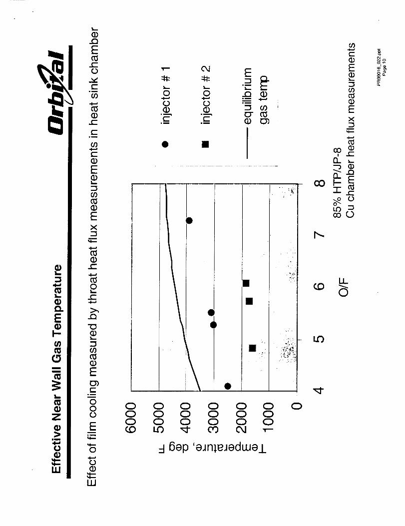
The heat sink chamber
provides an average heattransfer rate in the throat
that can be used to infer
the effective gas
temperature. The
effective near wall gas
temperature provided by
each injector was
determined from the
thermocouplemeasurements over a
range of O/F conditions
as shown in Fig. 16.These results were then
used to determine the
viable operatingconditions for ablation
testing with the composite nozzle. The agreement between the measured and predicted
erosion rates were excellent. After the long duration (140 s) test, the chamber was cut
into sections. A comparison of the measured and predicted char depth in the throat also
indicated excellent agreement with less than 5% error. The low near wail gas
temperatures indicated in Fig. 6, along with the low throat erosion rate (< 0.001 in/s),
prove the efficacy of the O/F biasing method to achieve minimal erosion while
maintaining minimal performance loss.
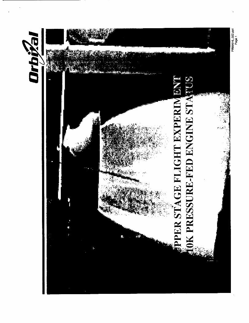
The USFE Mission
The purpose of the Upper Stage Flight Experiment (USFE) is to demonstrate key
technologies necessary to the operation of an inherently simple propulsion system with an
innovative, state-of-the-art structure. Two key low-cost vehicle elements will be
demonstrated - a 10,000 Ibf thrust pressure-fed engine and an integrated composite tank
structure. These technologies will be demonstrated through numerous development tests
culminating in an actual flight.
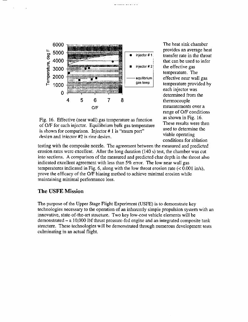
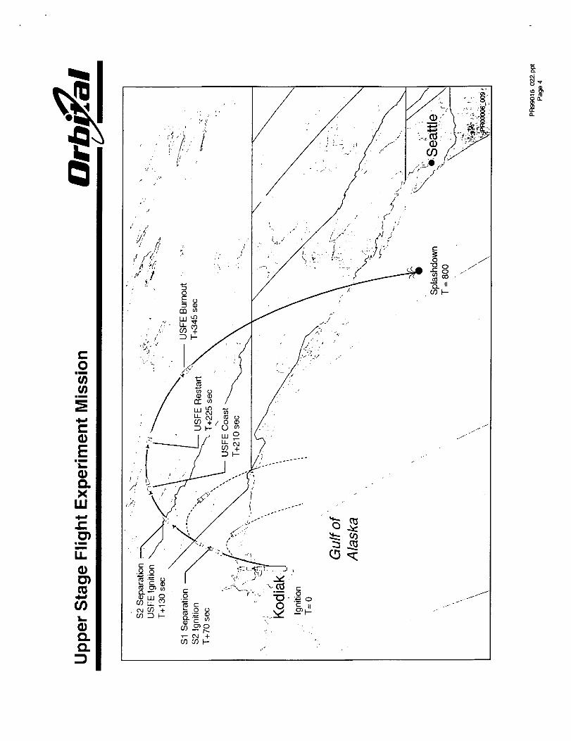
TheUpperStageFlight Experimentwill fly asthethird stageaboardanOrbitalSuborbitalProgram(OSP)suborbitallaunchvehicle.Figure 17showsanoverviewof theUSFEmission. TheUSFE/OSPmissionwill fly outof theAlaskaSpaceportonKodiakIslandin November2001.
S2 SeparationUSFE IgnitionT+130 sec
St Separation ..... .. ,- USFE Burnoul
$2 Ignition USFE Restart T+345 sec
T+70 sec ºr+225 sec
USFE Coast
\\
Ignition _ __ ._ .T= 0
\\
Gulf of\
Alaska ,"-,\
\ °
\
Fig. 17. The Upper Stage Flight Experiment.
Integration of the USFE and the OSP nosecone takes place at Orbital's facility in
Arizona. The OSP vehicle avionics are located in the nosecone. After integration and
test, including mission simulation testing, the USFE/nosecone assembly is shipped to the
Alaska Spaceport for integration with the first and second stage of the OSP launch
vehicle. After vehicle integration, checkout, and final mission simulation testing, USFE
is loaded with propellants for launch. The propellant loading sequence consists of
loading helium, nitrogen (for the attitude control system), JP-8, and hydrogen peroxide.
Final checks are done and the count down to launch proceeds.
After stage 1 and 2 burn, USFE is separated from the 2 "d stage by an ordnance separation
event in the interstage. The vehicle is exo-atmospheric prior to stage 2 burn out.
Immediately after Stage 2/USFE separation, USFE goes through its engine startup
sequence. After engine start, USFE will burn for 80 seconds, shutdown, coast for 15seconds, then restart and burn for 120 seconds. After shutdown USFE and the OSP
nosecone reenter the atmosphere marking the end of the mission.
Draft-3/3/00
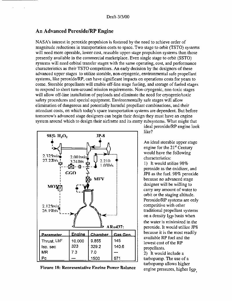
An Advanced Peroxide/RP Engine
NASA's interest in peroxide propulsion is fostered by the need to achieve order of
magnitude reductions in transportation costs to space. Two stage to orbit (TSTO) systems
will need more operable, lower cost, reusable upper-stage propulsion systems than those
presently available in the commercial marketplace. Even single stage to orbit (SSTO)
systems will need orbital transfer stages with the same operating, cost, and performance
characteristics as their TSTO competitors. An early decision by the designers of these
advanced upper stages to utilize storable, non-cryogenic, environmental safe propellant
systems, like peroxide/RP, can have significant impacts on operations costs for years to
come. Storable propellants will enable off-line stage fueling, and storage of fueled stages
to respond to short turn-around mission requirements. Non-cryogenic, non-toxic stages
will allow off-line installation of payloads and eliminate the need for cryogenic/toxic
safety procedures and special equipment. Environmentally safe stages will allow
elimination of dangerous and potentially harmful propellant combinations, and their
attendant costs, on which today's space transportation systems are dependent. But before
tomorrow's advanced stage designers can begin their design they must have an engine
system around which to design their airframe and its many subsystems. What might that
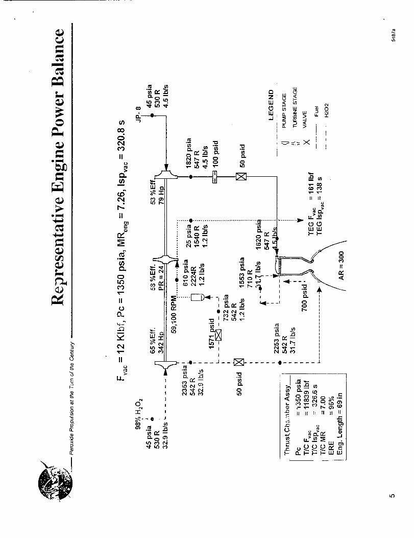
.IP-8
MFV
AR=437:
PRrRrn_f_r
Thrust, LbF
ISD, sec
MR
Pc
Enaine
10.000323
7.3
Chamher
9.855
329.2
7.0
1500
P.a_qGep.
145
140.6
671
Fieure 18: Renresentative Eneine Power Balance
ideal peroxide/RP engine looklike?
An ideal storable upper stage
engine for the 21" Century
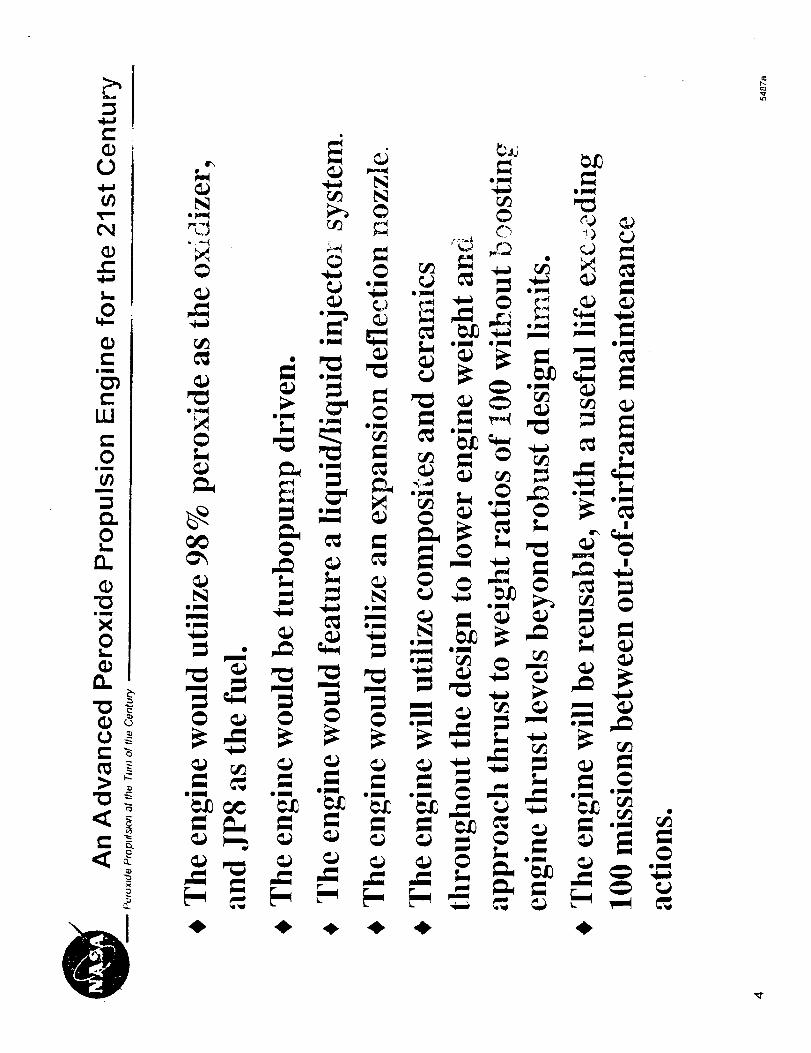
would have the followingcharacteristics:
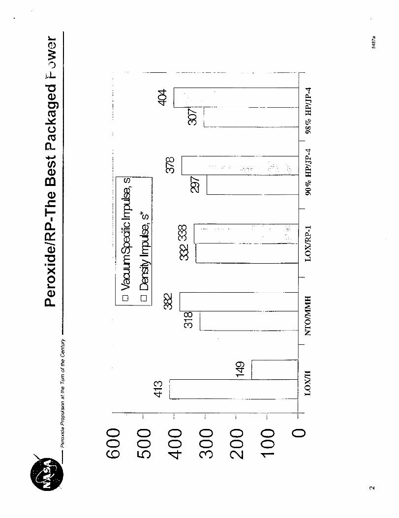
1) It would utilize 98%
peroxide as the oxidizer, and
JP8 as the fuel. 98% peroxide
because no advanced stage
designer will be willing to
carry any amount of water to
orbit or the staging altitude.
Peroxide/RP systems are only
competitive with other
traditional propellant systems
on a density Isp basis when
the water is minimized in the
peroxide. It would utilize JP8
because it is the most readilyavailable RP fuel and the
lowest cost of the RP
propellants.
2) It would include a
turbopump. The use of a
turbopump allows higher
engine pressures, higher Isp '
Draft-3/3/00
lower stagestructuralweights,andmoreflexibility in stagedesign.Theturbopumpwouldbea minimal partscount,low cost,decomposedperoxidegasgeneratordrivendesign.Theturbopumpwouldbe robust,buthavearecurringprice below$100,000.Theturbopumpwould featurecompositeandceramicmaterials,eliminatingallmetallicpartsandtheir associatedweights.
3) It would featurealiquid/liquid injectorsystem.Decompositionof largeamountsofperoxideby catalystprior to JP8injectionis anunnecessaryprocessstepwhenthermaldecompositioncanbeaccomplishedwith properinjectorandchamberdesign.
4) It wouldutilize anexpansiondeflectionnozzle.Packagingtheenginewithin thestagestructurein orderto maximizetheavailableboosteror advancedstagevolumeforpayloadwill eliminatetheuseof today'slargebell nozzles.
5) It will featurean integratedfluid/gascontrolmodule.Today'ssnakenestof discretevalvesfor eachfunction,connectingplumbing,controllersandwiring representascostinefficient adesignascanbegenerated.
6) It will bereusable,with ausefullife exceeding100missionsbetweenout-of-airframemaintenanceactions.It will bedesignedfor easeof maintenancewhile installedin theairframe.
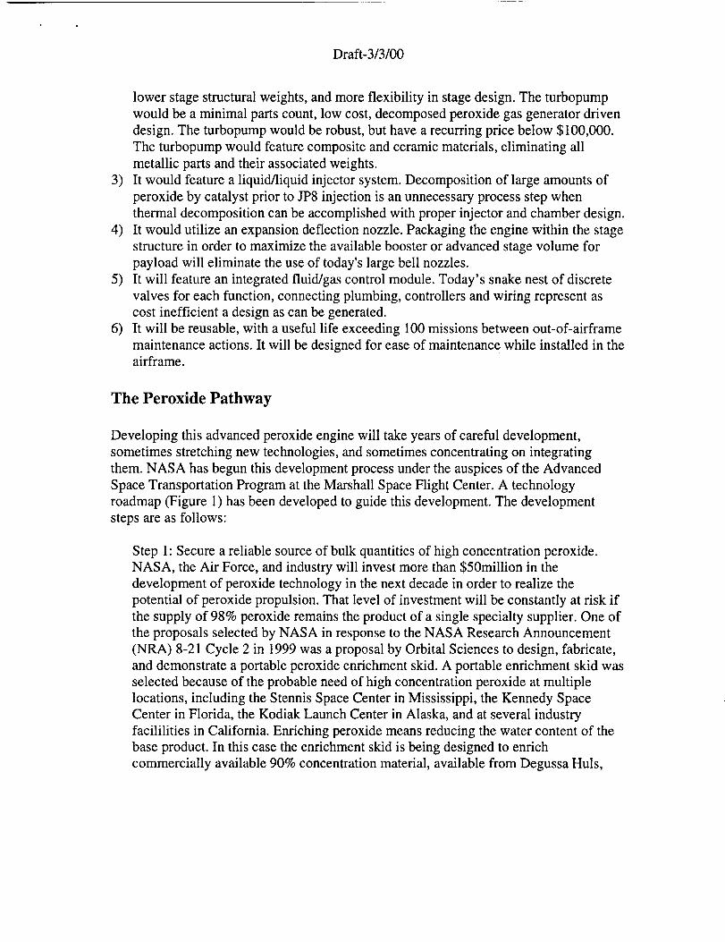
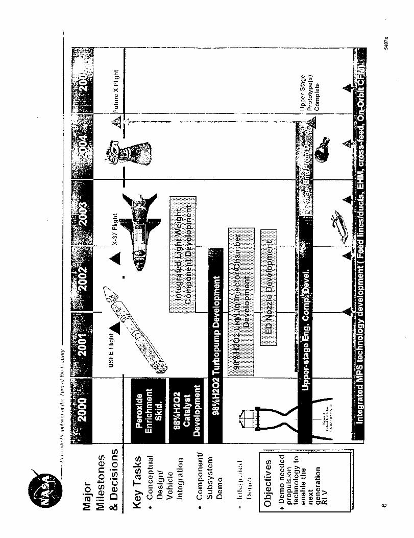
The Peroxide Pathway
Developing this advanced peroxide engine will take years of careful development,
sometimes stretching new technologies, and sometimes concentrating on integrating
them. NASA has begun this development process under the auspices of the Advanced
Space Transportation Program at the Marshall Space Flight Center. A technology
roadmap (Figure 1) has been developed to guide this development. The development
steps are as follows:
Step 1: Secure a reliable source of bulk quantities of high concentration peroxide.
NASA, the Air Force, and industry will invest more than $50million in the
development of peroxide technology in the next decade in order to realize the
potential of peroxide propulsion. That level of investment will be constantly at risk if
the supply of 98% peroxide remains the product of a single specialty supplier. One of
the proposals selected by NASA in response to the NASA Research Announcement
(NRA) 8-21 Cycle 2 in 1999 was a proposal by Orbital Sciences to design, fabricate,
and demonstrate a portable peroxide enrichment skid. A portable enrichment skid was
selected because of the probable need of high concentration peroxide at multiple
locations, including the Stennis Space Center in Mississippi, the Kennedy Space
Center in Florida, the Kodiak Launch Center in Alaska, and at several industry
facililities in California. Enriching peroxide means reducing the water content of the
base product. In this case the enrichment skid is being designed to enrich
commercially available 90% concentration material, available from Degussa Huls,
Draft-3/3/00
MajorMilestones &
Decisions
Key Tasks• Conceptual
Design/
Vehicle
Integration
• Componenff
Subsystem
Demo
• lntegralpd
l)_!mll
Objectives* Demo needed
propulsiontechnology toenable thenextgenerationRLV
Figure 19-Peroxide Propulsion Technology Development Roadmap
FMC, and X-L Space Systems, to a 98% concentration material at a rate of 1000
pounds per day. The chosen enrichment process is crystall fractilization. The skid
design and process controls are being engineered by Orbital's design partner Degussa
Huls. The on-site enrichment process allows tighter control of product quality. It also
allows concentrated product to be produced only as needed rather than stockpiled,
thereby ensuring a safer operation. The enrichment skid also allows shipment of the
less reactive 90% concentration product, and avoids exposure of the general public to
the shipment of 98% material. The enrichment skid will be completed in 2000.
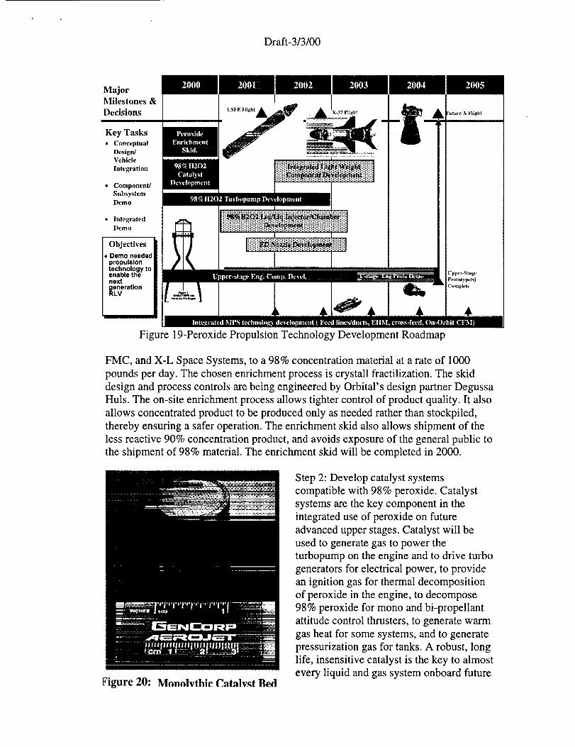
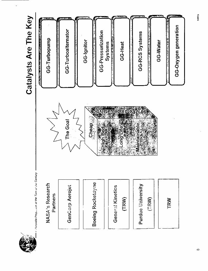
_igure 20: Monolvthic Catalv._t Bed
Step 2: Develop catalyst systems
compatible with 98% peroxide. Catalyst
systems are the key component in the
integrated use of peroxide on future
advanced upper stages. Catalyst will be
used to generate gas to power the
turbopump on the engine and to drive turbo
generators for electrical power, to provide
an ignition gas for thermal decomposition
of peroxide in the engine, to decompose
98% peroxide for mono and bi-propellant
attitude control thrusters, to generate warm
gas heat for some systems, and to generate
pressurization gas for tanks. A robust, long
life, insensitive catalyst is the key to almost
every liquid and gas system onboard future
Draft-3/3/00
advanced upper stages. Preliminary work on 98% peroxide catalyst was done in the
50s and 60s, but none of it resulted in definitive fielded systems. Aerojet, Boeing
Rocketdyne, TRW, TRW partner General Kinetics, and TRW partner Purdue
University were all selected by NASA in response to NRA8-21 cycle 2 to work on
advanced catalyst for decomposition of 98% peroxide. In addition, Pratt &Whitney is
performing research on 98% concentration catalyst systems on internal company
funds. Competition is responsible for more technical innovation in industry than any
other factor and this competition in the development of an advanced catalyst all but
ensures success. All of the companies offer a different solution. And the costs to
explore these potential solutions are moderate. The catalyst development work is
planned for completion in 2000.
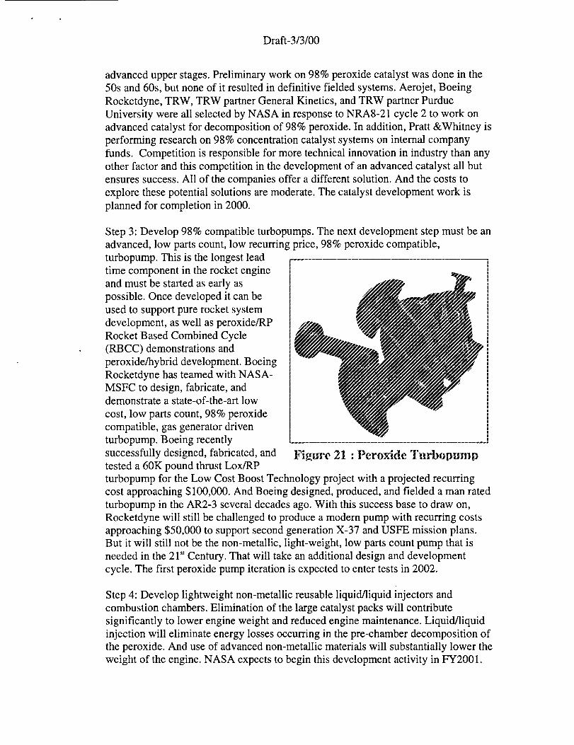
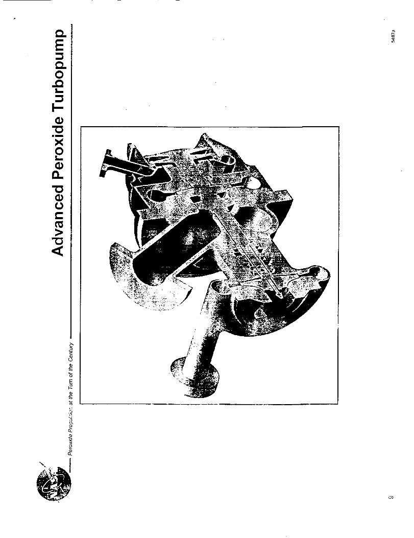
Step 3: Develop 98% compatible turbopumps. The next development step must be an
advanced, low parts count, low recurring price, 98% peroxide compatible,
turbopump. This is the longest lead
time component in the rocket engine
and must be started as early as
possible. Once developed it can be
used to support pure rocket system
development, as well as peroxide/RP
Rocket Based Combined Cycle
(RBCC) demonstrations and
peroxide/hybrid development. Boeing
Rocketdyne has teamed with NASA-
MSFC to design, fabricate, anddemonstrate a state-of-the-art low
cost, low parts count, 98% peroxide
compatible, gas generator driven
turbopump. Boeing recently
successfully designed, fabricated, and
tested a 60K pound thrust Lox/RP
11
IIIiI
1
1111I
1
1
iIII1III
Figure 21 : Peroxide TurbopumrJ
turbopump for the Low Cost Boost Technology project with a projected recurring
cost approaching $100,000. And Boeing designed, produced, and fielded a man rated
turbopump in the AR2-3 several decades ago. With this success base to draw on,
Rocketdyne will still be challenged to produce a modern pump with recurring costs
approaching $50,000 to support second generation X-37 and USFE mission plans.
But it will still not be the non-metallic, light-weight, low parts count pump that is
needed in the 21 s' Century. That will take an additional design and development
cycle. The first peroxide pump iteration is expected to enter tests in 2002.
Step 4: Develop lightweight non-metallic reusable liquid/liquid injectors and
combustion chambers. Elimination of the large catalyst packs will contribute
significantly to lower engine weight and reduced engine maintenance. Liquid/liquid
injection will eliminate energy losses occurring in the pre-chamber decomposition of
the peroxide. And use of advanced non-metallic materials will substantially lower the
weight of the engine. NASA expects to begin this development activity in FY2001.
Draft-3/3/00
Step 5: Develop a lightweight non-metallic reusable expansion deflection nozzle.
Axial length to cross-sectional diameter ratios in excess of 1:3 will be necessary to
meet future engine packaging requirements. Bell nozzles can not hang out the back of
re-entering upper stage flight vehicles the way SSMEs do on the Shuttle.
Step 6: Develop a light-weight, non-metallic, fluid/gas control module. NASA and
industry took a step in this direction by designing, fabricating, and flight testing a
composite hydrogen control valve on the NASA/McDonnell Douglas DC-XA
program in 1996. But more than fabrication of individual valves must be done.
Consolidation of fluid and gas control functions, elimination of brackets and tubing,
and relocation of components for ease of maintenance and test must dominate new
designs.
Because safety is of paramount importance in dealing with such an energetic oxidizer,
FMC Corporation was selected to perform hazardous materials testing of 98%
concentration peroxide. Almost all of the data pertaining to safe handling and storage of
98% peroxide is three or more decades old. More current data will be required to satisfy
today safety analyses and review boards. FMC, as a past American supplier of high
concentration peroxide, is eminently qualified to perform these tests and establish the
required safety data. This work is expected to be completed in 2000.
Conclusion
Five years ago peroxide/RP propulsion figured in no-one' s plans. Now at the turn of the
century peroxide/RP propulsion is returning to flight status aboard joint Air Force/NASA
research vehicles demonstrating it's capability to meet both expendable and reusable
mission needs. And development of new peroxide/RP engines has begun to take
advantage of the new materials and design processes available today to reach new
performance levels. A successful development program will lead to long term
commercial application of this technology to 21st century space transportation systems.
Acknowledgements
The authors would like to acknowledge the help of Robert Ross, Doug Peters, Dave
Mason, Scott Anderson, Jerry Golden, and Charles Cornelius of Orbital Sciences
Corporation; Robert Bruce, Gary Taylor, Don Beckmeyer, Stan Warren and Scott Dracon
of NASA Stennis Space Center; Fred Vaughn and Ray Nichols of Lockheed, Jim
Guerrero and Dave Perkins of Air Force Phillips Lab; Ray Walsh of Schafer Corporation;
Mark Ventura of General Kinetics; Ken and Norm Christensen of American Automated
Engineering; and Abdi Nejad, P.-K. Wu, and Phil Morlan of Kaiser-Marquardt.
References
1. "The AR2-3, AR-3 and AR-4 Rocket Engines Technical Information and Program
Plan", BC72-29, 1972.
2. "Rocketdyne AR Engines", BC72-21, 1972.
Draft-3/3/00
3. "Air Force Evaluation of the F-86F with AR2 Rocket Augmentation", AFFTC-TR-60-
39, October 1960.
4. "Final Report for the XLR46-NA-2 Aircraft Superperformance Rocket Engine", R-
1726, October 30, 1959.
5. "AR2-3 IR&D Engine Testing At Stennis Space Center", internal Rocketdyne report,unreleased.
6. NASA-MSFC website on Pathfinder vehicles.
"X-37: Taking the X-Planes to Orbit", Aviation Week, August 9, 1999.References
IWu, P.-K., Fuller, R.P., Moflan, P.W., Ruttle, D.W., Nejad, A.S., and Anderson, W.E.,
"Development of a Pressure-Fed Rocket Engine Using Hydrogen Peroxide and JP-8,"
AIAA Paper No. 99-2877, Los Angeles, CA, June 20-24, 1999.
2Morlan, P., Wu, P., Nejad, A., Ruttle, D., Fuller, R., and Anderson, W.E., "Catalyst
Development For Hydrogen Peroxide Rocket Engines," AIAA Paper No. 99-2740, Los
Angeles, CA, June 20-24, 1999.
3Anderson, W.E., Crockett, D., Hill, S., Lewis, T., Fuller, R., Morlan, P., Ruttle, D., Wu,
P.-K., and McNeal, C., "Low Cost Propulsion Using a High-Density, Storable, and Clean
Propellant Combination," AIAA Paper No. 98-3679, Cleveland, OH, July 13-15,
1998.
4Nozzle Aero Thermochemistry (NAT) Computer Code Version 2.0, February 1994,
Aerotherm Corporation, Huntsville Operations, Huntsville, AL.
SCMA90S, December 1990, Acurex Corporation, Aerotherm Division, Huntsville
Operations, Huntsville, AL.
_w
"0
O|m
c_
e
Lo
C_
0
0
I
X0
[] []
R_
00'1"-"
cO
cO
J i I J i
0 0 0 0 0 00 0 0 0 0 0r...O _ ._- cO C'q _--
!
0
0
Z
©
0

|m
C
CLU
<
_: .,_s:_-.;!_!,__
_'._ .,_.J_i_ __._V.--__,
E.C
G')
|m
L_
0
&
O
o_
!
8
a_
o_,._O_O _'- 143 --143
Or"Oo L.O _io4 o04c3 r43 _t" _o . AO3t43 C',4_ (.O _--cO O4 O40 _ _--
__ _o_" _,
o e ._ × _,=_ _ _r, ff-- "= ._, "_ IE
C_r-
gm
IL_iim
U.-I-J

r-0
c_I,.
(1)
0
&n,,
C_
U..
(D
E
.oc_
c_
co
(1)
0
or)
ii immm
(v.j&n,',<
o0
o_
Q.
E
Cim
CLU
"C3
c:L IJ_v
Q.E
4)
\
I:
i,
....
i
iI
0
0- _-f-j
o
c)
o_
E
_0
0
!
o
:),_0
o
_D
at.
¢D
E
C'q
(oesl#) eIRJMOI-I xO
i7 E
I
0
13_
$.£3E03
(b
O_
t-O
nX0
+LLX0
+C3 0 C) 0 0 0 0 OC3 L.r) C) kf3 (:3 14) 0 L{)
(6!sd) oJn_aad
0
cO
CO
C_
cO v
E!--
(D
0
I
_0
r_
t_
b
_o
O.
q)
_o
0
0
v
EF-
oo
c_
c_
g VIll_
q_
4_
_f
q_
Im I_
O_ .......
lmm
Im
Oc_O
0
C_c_
c_
c_c_
c_
io
E
C_
0_Tim
0
c_
C_
_D
4_
_L
i+ +iQ_ T-- O0 0"_C0
-- -- m
Lt_
m ----
tf_ <j_
_ _ o_ _I
++_ + i+ i _°+!_
T--
(Jr-(D
(/'j..C:C.)C:
r,..(v,j
cDtJe-
0"
c-O
iim
(Rt_
c_
E
v_
_D
C:
r,..¢,.)
E
c:L
e
r_
O"Je-
iim
c:
._i
r,..
q,),.C:
C:
u_
x
co
_L
Q_O.
Q
0.
ii
E
0
L_
I-
C/)
c_
c_
.0 0w_
!
rr
"0
I--.
0
0
¢..
I--.
¢-
¢.. ¢-
0
.m .m
or" _- ¢-
0
0
¢_ ¢-
c"
_oI _
on
I:1.
ILl
0
0
C:m
0
0
E:im
c-
r-
r.oII
LL
©cO
>
im
c-O
0c-
i!
0gl
cO
e-
Rm
Rm
LU
r-
"_"o•..Q "I:::
!
0c'J
c_ c-C:) .r-
o
0o
o[]o
o
[]
o
!
t
o o
,0 ela
0
_b
o
Lr_
rr0.
)O.
I-
(.9mm
i1,1
,.0 09
r-
(- Eo .,- o4 E ¢
0 0 _Q CD
¢ -_., ._.,l.- .... (D
g _2i c-
O0 L =_ U3 _E moX
M,,--
"_o / ,t " _ ,.oe"N •
\E
.c:: \ .......! , _-0o 0 0 0 0 0 0 0o 0 0 0 0 0 0
0 0 0 0 0 0
-4 iep 'e._nleJedLue.L(I,)
LLI
_o
¢¢n
r-LU
_-___?_
'&
rrr_
E
&
Oi.!++..,a _
.m
t-"
in
ILlIJ.u'J
I
0
< +: .. . ---
_- :: ! -- : . :: ,: -
.2 ::
Z : + - .... :- z
........... • ................... L.+.....
l:r_+'
C0
ii
illill
IE
ii
Ii
c_XW
_=
mi
LL
c_c_
/
J /!
,r/
_,r/ •
',_ h'
,>,'i.#
L:
o
m co
//
//
/
//
/
7
////__
-" ('i _./ //i I
i 1 I_
. / f_"
L t..," .f_
.fill--
. i.l.lu')
• :_ GO Jr
• ?,,, _ , ..
/ g:_ /I w m
l co_l o a) f
%;
. , WO _.
•,_-L_A/ __ >
__ '" _ -"'" '_iA 7_-.----r' ,..-' ),,
,:-;\I ........
"I__,"/ " /;'72"" ' ""_
g i
_-- 00, +
O_O')k-
x . .
i
j
i' fJi.
E
O0,.
ft.Q.
7
Q
m
i,i.l l,,,,,.lI.l"l
&.-.-.-i_
II
<_iii
,.<>_
L
II0
II
Ii
z _ ,<
0 _ w _ o
•_ ._ [ --_._o
o O C'_l¢',,I _e'i _ ,
o-1-_1 mJ
_..t.... ..-J--'_ _ .,_
II II
1.1 _ime'_>_
, ..... • ................................ m........ ........ I_ l.,t_ _: m ,.,,,, u> ,_ ,_ 0 r,..O
ill iii: '_'-'.-._ _ ._: t.-_o -- o t"_ ..c I-. I,-
' "_'-- _ --I• _" i",l "_. ,_ _ ...'I
i <<><""" _3 ', _ i._-I "-- 01
e_
o"
_.-e +J0:3 03
IM '_ ,e-
"O-- .1
°+'m+°o+,--,r ,,L,-- C") " _<_j
.-_1 I1 II h Ti II II7 e-,'d
_1 o 0 0 C'j W _
_-1 _.pPPww
@o
_ii!iii_iii_!:i:i:_i!ii_iiii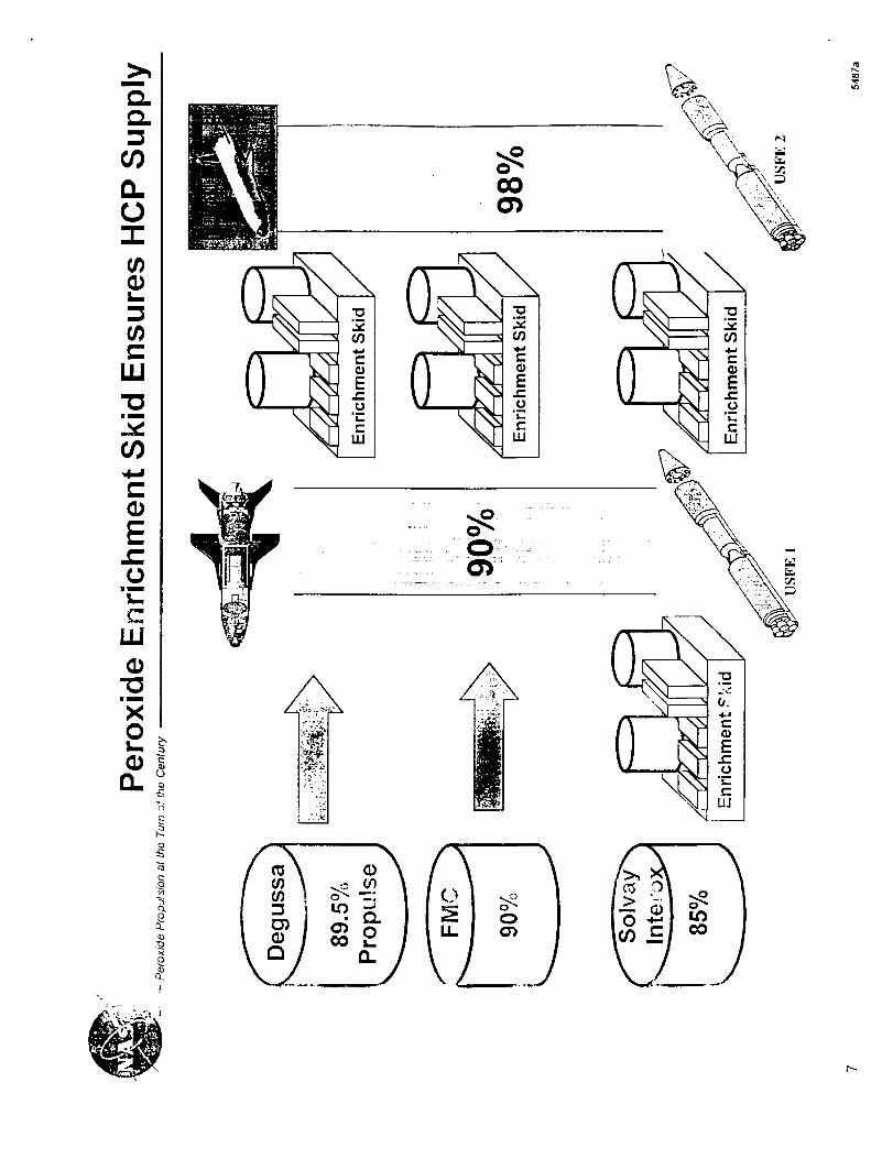
I
(/)
L_
LLI
_bIII
LIJ
"I:1
X
!
,IiI
/%L _.__.:ii.
\
e-
\
_ oi
4 E
,i
e-Ill
,%"_ I
u] I
::l ' L_
.
,....
l--
i0
8
E
el.
r3
I
if)
z
00e- e-
ii
0113
I °t--
cO
0
Im
Im
X0Lm
0.."0(_
Cc_>
"0
_j(J
c_
_J
i,i_.
_J