1
SUNFEST Technical Report TR-CST01DEC05, Center for Sensor Technologies, Dept of Electrical andSystems Eng, Univ. of Pennsylvania, Philadelphia, PA 2005
University of Pennsylvania
SUNFEST
NSF REU ProgramSummer 2005
PATH PLANNING MOBILE ROBOTICS
NSF Summer Undergraduate Fellowship in Sensor TechnologiesLouie Huang (Electrical and Systems Engineering) - University of Pennsylvania
Advisor: Dr. George Pappas
ABSTRACT
One of the fundamental problems in the field of robotics is path determination andmotion planning. The project described in this paper focuses on path determination in aknown environment. The goal is to enable a mobile robot to successfully navigate anenvironment according to a specified temporal logic formula. On a high level, temporallogic formulas can effectively provide the robot with directions on where and when to go.As part of this project, a program will be developed to formulate a continuous path planthat will fulfill the temporal logic formula supplied for the robot to follow.
In this project, the ActivMedia Pioneer 3-DX robot will be used. This robot model waschosen because it is preconfigured for basic navigation. Preprogrammed with algorithmsfor shortest path determination, obstacle avoidance, and localization, the Pioneer 3-DX isalso capable of new navigation techniques that can be programmed in C and C++. Mapsof known environments can be generated by the Pioneer 3-DX. A graphical user interfaceprogram will utilize these maps in conjunction with user supplied directions as expressedby a temporal logic formula to construct a path plan. The path determined by the programcan then be relayed back to the robot for implementation.
2
Table of Contents
1. INTRODUCTION p. 3
2. OVERVIEW OF CONTINUOUS PATH CREATION p. 3
3. ROBOT DESCRIPTION3.1 Pioneer 3-DX p. 53.2 Robot Behavior p. 7
4. GRAPHICAL USER INTERFACE FOR ROBOT MAPS4.1 Purpose p. 84.2 Development of the GUI p. 9
5. DISCUSSION AND CONCLUSIONS p. 13
6. RECOMMENDATIONS p. 14
7. ACKNOWLEDGEMENTS p. 14
8. REFERENCES p. 15
APPENDIX p. 16

3
1. INTRODUCTION
In the constantly evolving field of robotics, path determination is a topic that attractsmuch interest because of its numerous potential applications. A robot which can plan itsown path when given destinations and certain guidelines can be used for patrol andmobile surveillance or transport and delivery of items. Using robots for such applicationscan not only offer convenience to users but can also save lives when employed in militarysituations. Such beneficial uses validate the importance of research pertaining to pathdetermination.
The project that this paper is based upon focuses on determining a path that fulfills aspecified direction represented by a temporal logic formula. It stems from an earlier paper[1] published by two graduate students -- Georgios Fainekos and Hadas Kress-Gazit --and Professor George Pappas of the General Robots Automation Sensing Perception(GRASP) Laboratory at the University of Pennsylvania. The paper presents the methodby which continuous path plans can be generated for a robot in a known environment.The continuous path will be implemented by the robot and should satisfy temporal logicinput. The overall goal behind this study is to allow users to effectively direct a robot on ahigh communication level that is close to natural human language in the form of temporallogic [1].
The sections that follow this introduction will further explain the details of the projectand the progress made to date. Section 2 will discuss the background of the developmentof a continuous navigation path. Section 3 will introduce the ActivMedia Pioneer 3-DX,the specific robot that will be used in this project. This section will also present some keynavigation behaviors that the Pioneer 3-DX is capable of and discuss how new behaviorscan be programmed. Section 4 will cover the purpose and the development of the robotmap graphical user interface (GUI) program, which will be used to ultimately generatepaths for the robot. In section 5, discussions and conclusions of the overall project arepresented. Section 6 covers recommendations for future work and Section 7 is dedicatedto acknowledgements. All references can be found in Section 8.
2. OVERVIEW OF CONTINUOUS PATH CREATION
The following description of continuous path creation was originally presented anddiscussed in the research paper [1] that served as a foundation for this project. In theinterest of brevity, the prior work on continuous path creation will be briefly summarizedhere. Readers interested in further detail should consult the original source.
The process of creating a continuous path for implementation begins with navigationdirections. Directions are to be given in the form of temporal logic formulas. Temporallogic formulas can delineate multiple destinations and specify when the destinationsshould be reached. For example, an instance of a temporal logic formula can be used todirect the robot to visit all rooms but not to visit a certain room until all other rooms havebeen visited. Temporal logic formulas are close to human language, providing greateraccessibility to users who would therefore not need to be concerned with the lower
4
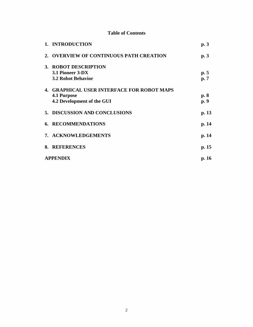
implementation of the robot’s movements. A direction alone is not sufficient for pathgeneration. The robot must know its environment through a map of the environment thatpertains to the directions provided.
Figure 1: 2-D environment map of a floor in the Levine Building
Another necessary component for creating a path is a 2-D graphical map (as illustrated inFigure 1) delineating, from a bird’s eye view, walls and obstructions of the environmentto be navigated. The next step in arriving at a continuous path is to develop a discretepath through model checkers. To develop a discrete path, the 2-D graphical map needs tobe partitioned into discrete units. Although other partitioning methods could also beconsidered, triangulation has been recommended because of its relative ease incomputation and readily available algorithms. The destinations then specified by thetemporal logic formula will each be composed of at least one triangle. A discrete path canbe created that visits the necessary triangles to fulfill the temporal logic formula. Upongeneration of a discrete path, a continuous path can be developed. The continuous pathmust obviously still satisfy the original temporal logic formula. For further detail on theprocess of continuous path creation, please refer to the original path planning paper [1].
5
3. ROBOT DESCRIPTION
3.1 Pioneer 3-DX
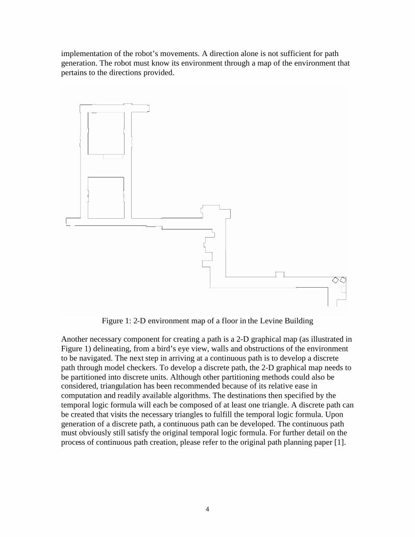
The Pioneer 3-DX robot made by ActivMedia Robotics is an all purpose robot suitablefor research [2]. The robot is readily capable of basic navigation functions. One of themost important features of the Pioneer 3-DX is its ability to localize itself fairlyaccurately within a known environment. In Figure 2, the Pioneer 3-DX is observed fromits front. Localization is made possible by the eight sonar shown in the figure; two of thesonar are hidden from view as they are mounted on the sides of the robot. The laserrangefinder that sits on top of the robot also assists with localization. The laserrangefinder has the advantage of greater range and accuracy than the sonar. However, thesonar is necessary to detect low lying obstacles close to the ground.
Figure 2: Front View of Pioneer 3-DX
Sonar
LaserRangefinder
6
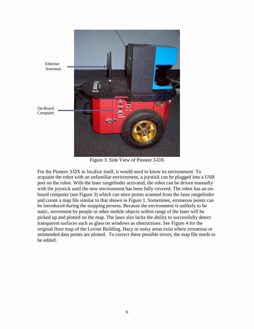
Figure 3: Side View of Pioneer 3-DX
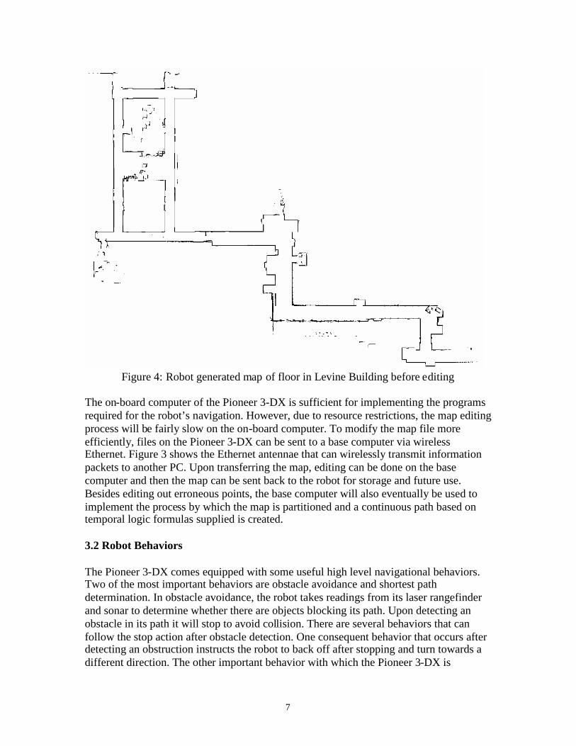
For the Pioneer 3-DX to localize itself, it would need to know its environment. Toacquaint the robot with an unfamiliar environment, a joystick can be plugged into a USBport on the robot. With the laser rangefinder activated, the robot can be driven manuallywith the joystick until the new environment has been fully covered. The robot has an on-board computer (see Figure 3) which can store points scanned from the laser rangefinderand create a map file similar to that shown in Figure 1. Sometimes, erroneous points canbe introduced during the mapping process. Because the environment is unlikely to bestatic, movement by people or other mobile objects within range of the laser will bepicked up and plotted on the map. The laser also lacks the ability to successfully detecttransparent surfaces such as glass on windows as obstructions. See Figure 4 for theoriginal floor map of the Levine Building. Hazy or noisy areas exist where erroneous orunintended data points are plotted. To correct these possible errors, the map file needs tobe edited.
EthernetAntennae
On-BoardComputer
7
Figure 4: Robot generated map of floor in Levine Building before editing
The on-board computer of the Pioneer 3-DX is sufficient for implementing the programsrequired for the robot’s navigation. However, due to resource restrictions, the map editingprocess will be fairly slow on the on-board computer. To modify the map file moreefficiently, files on the Pioneer 3-DX can be sent to a base computer via wirelessEthernet. Figure 3 shows the Ethernet antennae that can wirelessly transmit informationpackets to another PC. Upon transferring the map, editing can be done on the basecomputer and then the map can be sent back to the robot for storage and future use.Besides editing out erroneous points, the base computer will also eventually be used toimplement the process by which the map is partitioned and a continuous path based ontemporal logic formulas supplied is created.
3.2 Robot Behaviors
The Pioneer 3-DX comes equipped with some useful high level navigational behaviors.Two of the most important behaviors are obstacle avoidance and shortest pathdetermination. In obstacle avoidance, the robot takes readings from its laser rangefinderand sonar to determine whether there are objects blocking its path. Upon detecting anobstacle in its path it will stop to avoid collision. There are several behaviors that canfollow the stop action after obstacle detection. One consequent behavior that occurs afterdetecting an obstruction instructs the robot to back off after stopping and turn towards adifferent direction. The other important behavior with which the Pioneer 3-DX is
8
preprogrammed is shortest path determination in a known environment. This behaviorrequires a map file of the environment and a home position on the map from where it willstart. A destination is also specified on the map. With this map file, the robot has theability to determine a shortest path while avoiding walls specified by the map.
The robot behaviors that the Pioneer 3-DX can exhibit are developed with theActivMedia Robotics Interface Application (ARIA). ARIA is programmed in C++ and itsclasses can be used to obtain readings from the robot’s sensors (sonar, laser, wheelmovements, etc.) [2].The robot’s basic movements -- as represented by direction -- andspeed can also be manipulated by ARIA. To develop new behaviors or modify existingnavigation behaviors, ARIA’s classes can be used in a C++ programming environmentsuch as Microsoft Visual Studio C++. Because the on-board computer has limitedresources, a programming environment such as Visual Studio would be operated at a basecomputer. A behavior after compilation then can be relayed back to the robot forimplementation through wireless Ethernet.
Using SRI International’s Saphira is often an easier way of implementing behaviors.Saphira is built utilizing ARIA and exists as a higher level programming environment forrobot behaviors. As a consequence of its higher level nature, programming in Saphira isinherently simpler than programming in C++ with ARIA. Saphira includes its ownprogramming language, Colbert, which is based on the C programming language [3].Colbert can be used to construct activities which provide navigational instructions to therobot upon implementation. Activities can be used to provide direct movementcommands which, for instance can tell the robot to move forward 10 meters and turn 90degrees. An activity can also be used to implement robot behaviors like obstacleavoidance by producing movement commands that depend on sensor readings [3].
Saphira also provides a simulator from which activities can be interactively tested andmodified. The robot used in the simulation can be an actual Pioneer 3-DX or a virtualrobot that emulates actual physical robot limits. The simulator allows multiple activitiesto be implemented. Of course, some activities may contradict others at times in whichone activity is directing the robot forward and another is simultaneously directing it tomove in reverse. To resolve such movement conflicts, Saphira uses a system by whicheach activity is given a priority. Direct motion directions are usually given precedenceover directions derived from sensor dependent behaviors [3]. For implementation ofactivities that involve a known environment, map files can be imported into the Saphirasimulator.
4. GRAPHICAL USER INTERFACE FOR ROBOT MAPS
4.1 Purpose
As discussed earlier, map files generated using the robot’s laser rangefinder may havemany points or representations of obstacles which should not be there. Also, walls thatreally exist may occasionally fail to appear if the wall is transparent. To correct theseproblems, a graphical user interface is needed to modify the map file. The map can be
9
readily accessed from a base computer that receives the file from the robot’s wirelessEthernet transmission. ActivMedia, the manufacturer of the robot already providessoftware to edit the map. The ActivMedia Mapper 3 program allows users to eliminateerroneous points on the map and insert lines that represent walls. It also allows users toadd goal points or destinations. Other additions that can be made to the map file includeforbidden regions and forbidden lines, which may not be actual obstructions in theenvironment, but are nevertheless areas that the user wants the robot to avoid.
The Mapper 3 is fairly useful but for the purposes of this project, it is not sufficient. Tofulfill the necessary specifications that would allow for the creation of the continuouspath, the Mapper 3 would need to be able to partition the map into discrete regionsthrough triangulation or some other partitioning method. In addition, the Mapper 3 wouldalso need to be able to accept temporal logic formulas and construct a discrete path thatwould ultimately lead to the continuous path for the robot to implement. Because theMapper 3 is not open source, it was decided that the best option would be to build agraphical user interface from scratch that -- in addition to including most of the Mapper3’s features -- would also allow for triangulation and path determination based ondirections given by temporal logic formulas. A crucial development requirement is thatthe modifications made to any maps through this robot map GUI must still maintain themap files’ compatibility with the robot.
The base computer that is used for the Pioneer 3-DX in this project is an IBM compatiblemachine that runs Microsoft Windows. To build the GUI as a Windows application,Microsoft Visual Studio .Net is used as the programming environment. C++ is used asthe programming language in Visual Studio .Net to construct the GUI as a Windows formapplication. The choice to use Microsoft Visual Studio .Net rather than otherenvironments is based on the ease of use that Visual Studio .Net offers for programmingGUIs using the Windows operating system. The classes provided by Visual Studio .Netparticular to Windows GUI programs simplify the GUI programming significantly.
4.2 Development of the GUI
The first function to be developed for the GUI was to display map files correctly. Mapfiles have the extension .map and can be accessed from a basic text editor. A map filegenerated by the Pioneer 3-DX always begins with the line “2D-Map”. The three linesthat follow this initial line pertain to obstacle points. Most environments would not haveobstacle points since walls are represented by lines. An obstacle point is most likely noisesince an obstacle point represents an object with an area of 1mm2. The three lines thatpertain to any existing obstacle points provide the minimum x and y coordinates andmaximum x and y coordinates in millimeters, as well as the number of obstacle points inthe map. The next three lines contain similar information for obstacle lines. Following theinformation on obstacle lines, the map file contains the definitions for forbidden areas,forbidden lines, goals, and home points in that order. Each line contains an individualdefinition represented by coordinates in millimeters and begins with the word “Cairn:”and the type of object defined. After definitions of these objects, the map file contains alist of lines each of which consists of 4 numbers and represents two coordinates in
10
millimeters. At the beginning of this list is the word “LINES” to signify that the listconsists of definitions for obstacle lines in the map. After this list is the list for obstaclepoints which begins with the word “DATA”. This list contains lines of 2 numbers, eachpair belonging to the coordinate pair of one obstacle point.
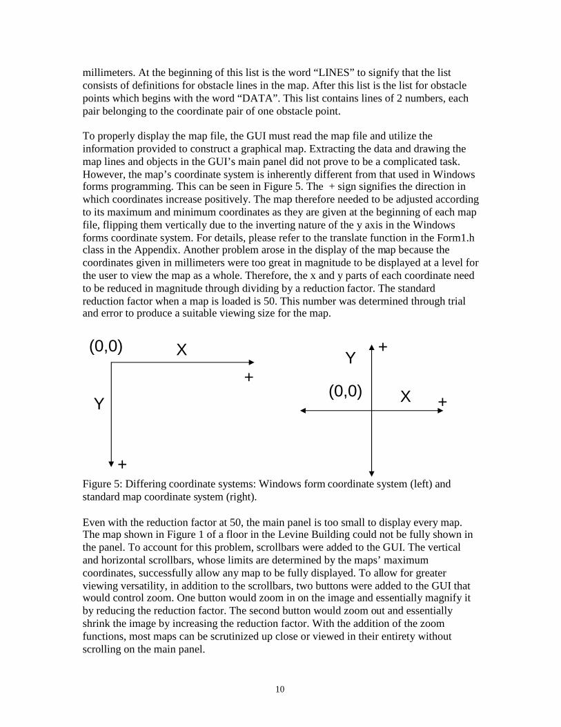
To properly display the map file, the GUI must read the map file and utilize theinformation provided to construct a graphical map. Extracting the data and drawing themap lines and objects in the GUI’s main panel did not prove to be a complicated task.However, the map’s coordinate system is inherently different from that used in Windowsforms programming. This can be seen in Figure 5. The + sign signifies the direction inwhich coordinates increase positively. The map therefore needed to be adjusted accordingto its maximum and minimum coordinates as they are given at the beginning of each mapfile, flipping them vertically due to the inverting nature of the y axis in the Windowsforms coordinate system. For details, please refer to the translate function in the Form1.hclass in the Appendix. Another problem arose in the display of the map because thecoordinates given in millimeters were too great in magnitude to be displayed at a level forthe user to view the map as a whole. Therefore, the x and y parts of each coordinate needto be reduced in magnitude through dividing by a reduction factor. The standardreduction factor when a map is loaded is 50. This number was determined through trialand error to produce a suitable viewing size for the map.
Figure 5: Differing coordinate systems: Windows form coordinate system (left) andstandard map coordinate system (right).
Even with the reduction factor at 50, the main panel is too small to display every map.The map shown in Figure 1 of a floor in the Levine Building could not be fully shown inthe panel. To account for this problem, scrollbars were added to the GUI. The verticaland horizontal scrollbars, whose limits are determined by the maps’ maximumcoordinates, successfully allow any map to be fully displayed. To allow for greaterviewing versatility, in addition to the scrollbars, two buttons were added to the GUI thatwould control zoom. One button would zoom in on the image and essentially magnify itby reducing the reduction factor. The second button would zoom out and essentiallyshrink the image by increasing the reduction factor. With the addition of the zoomfunctions, most maps can be scrutinized up close or viewed in their entirety withoutscrolling on the main panel.
X
Y
(0,0)
+
+(0,0) X
Y
+
+
11
The next functions to be implemented would allow for the additions of lines, goal points,and regions to a map file. Three buttons are added to the GUI each to represent a type ofobject to be drawn. For example, if the line button is pressed, the map file will onlyaccept the additions of lines. The reason these buttons are necessary is because eachobject is drawn similarly using mouse clicks. Lines are to be drawn by clicking down themouse button at the site where the first endpoint should be. The mouse button is helddown until the mouse is moved to the second endpoint. Goals are drawn by clicking anypoint in the map. For ease of viewing, goals are shown as small green squares. The centerof each square is the actual goal point. Regions are currently general custom structuresadded to the map. They may constitute future forbidden regions but they can also be usedto parameterize the map. Though triangulation is likely to be the parameterization methodto be used, the regions’ function is currently programmed to construct any polygon. Todefine a simple rectangle, the user only needs to click two points, which will always bethe upper left and the lower right vertices. The second point must be double clicked tosignify that the region will be a rectangle. Any other type of polygon can be constructedby mouse clicks. Each mouse click will define a vertex and the last vertex will require adouble click signifying the end of the region definition.
The added lines, goal points, and regions are not saved to any files when drawn onto amap. To register the additions made to the map, a save function was implemented in theGUI. To maintain the integrity of the original map file and its compatibility with therobot, the definition for each new line and goal must be added to the file in theappropriate areas with the appropriate syntax. The regions defined in the GUI are notnecessarily forbidden regions and therefore their definitions are stored in an auxiliary textfile with a filename that is always the name of the original map followed by “_regions”.In addition to saving the map files generated, the GUI will also save newly created mapfiles. The new map function in the GUI will generate a blank map with user defineddimensions. Maps newly created from the GUI will be indistinguishable in format fromrobot generated maps.
To date, the last function to be added to the GUI is the grid display and the positiontracker. When editing a map, it is useful to have a grid and to know the coordinates of theregion being modified. The grid function can be displayed when a map file is opened by aclick of the grid button. It can also be made invisible by a second click. Grid lines are1000 mm or 1 meter away from one another. As a result, the perceived distances shrinkor grow when a zoom is applied to the map. The position tracker simply tracks the mouseposition over the main panel where the map is displayed. Whenever the mouse moves,the tracker display located at the bottom right corner of the GUI is updated. Thecoordinates are displayed in millimeters and properly match the coordinate system nativeto the maps as portrayed in Figure 5.
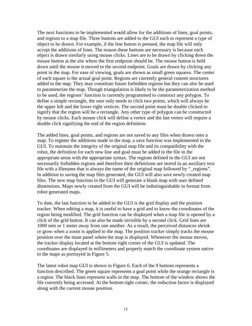
The latest robot map GUI is shown in Figure 6. Each of the 9 buttons represents afunction described. The green square represents a goal point while the orange rectangle isa region. The black lines represent walls in the map. The bottom of the window shows thefile currently being accessed. At the bottom right corner, the reduction factor is displayedalong with the current mouse position.
12
Figure 6: Snapshot of the robot map GUI; the map file t.map is being loaded at a reduction factor of 50
13
5. DISCUSSION AND CONCLUSIONS
The goal of the GUI in this project was to successfully access robot generated map filesand make modifications. In this aspect, the GUI in its current stage is fairly successful.With the GUI, new lines and goals can be added to existing maps or created in new maps.Robot compatibility with files modified and created by the GUI has been successfullymaintained. Regions which may be later used to partition the environment can be addedin the GUI. As the regions defined in the GUI are not directly useful to the robot, regionsmade to a map file are stored in separate text file with a similar name as the original map.The GUI, unlike the Mapper 3 offered by ActivMedia, does not allow users to add homepoints or forbidden areas or lines. For the project at hand, these features do not appear tobe needed. However, if this should change in the future, simple modifications can bemade to the robot map GUI program to allow for the addition of home points, andforbidden regions and lines.
One peculiarity of the GUI is that sometimes at large reduction factors, the coordinatedisplay may show coordinates slightly different from their expected appearance. Thescale of map coordinates stored is 1 mm per pixel on a monitor display. This scale canonly display a small piece of a map at any one time. To increase the distance per pixel sothat more of the map can be viewed at once on the screen without having to scroll around,a reduction factor is maintained by the GUI. The reduction factor reduces the magnitudeof all coordinates in the map. For higher calculation speeds, the division of coordinatesby the reduction factor is made an integer division, dropping the decimals. This roundingoff results in slightly inaccurate displays in coordinates of up to a 10 mm deviation undera reduction factor of 50. However, this slight inaccuracy is insignificant because 10 mmis relatively small in any normal sized environment. Also, if accuracy is needed, thezoom function can focus in on any area of a map. Though accurate work can be done byzooming in or lowering the reduction factor, the smaller magnified portion of the mapwill make editing work more difficult.
One key feature which has not been implemented in the GUI is an erase function.Currently, cleaning up erroneous data points and lines requires the use of Mapper 3. Theerase function is fairly important as the GUI will eventually need to function independentof the Mapper 3 in modifying maps. The only remedy for erasing lines or goals that wereinadvertently added is by reopening the map in the Mapper 3 and using its erase function.An alternative method is to open the map file in a text editor. This method is painstaking,however, as the user must know at least how many lines were added to the map file. Themost recent lines added are always added to the beginning of the list by the mappingGUI. Currently, the only method by which added regions can be removed from a map isto edit the region file with a text editor. A region file begins with a line that identifies thenumber of regions in the map, followed by region definitions that are individuallyidentified by a number representing the order in which each was created. Each regiondefinition also identifies the number of points in the region and all the points that pertainto the region. In order to be able to delete an erroneous region, a user would have to know
14
either the defining characteristics of a region as determined by number of points andpoint location, or when the region was added in reference to all other regions.
6. RECOMMENDATIONS
The most pressing focus for future research should be the creation of an erase function.Besides providing independence from the Mapper 3, the erase function is also crucial todeleting erroneous regions generated by the mapping GUI. These regions are notaccessible from Mapper 3 and currently can only be deleted through a text editor. Fileverification safeguards are another feature that could be added to enhance the robustnessof the current GUI. Currently, when opening a file, the open file dialog filter allows onlyfiles with .map extensions to be accessed. However, the program does not go further inverifying that the actual map file is valid. If the format is invalid or the map file has beentampered with, the program in its current state will just crash. Within the map file, themaximum and minimum points which determine the size of the map to be displayed needto be verified each time a map file is opened and corrected if they are inconsistent withdata. Occasionally, the maximum and minimum listed in the map file are not correct.This results in some lines not being displayed in the GUI because the lines are out of therange of the display created for the map.
The current version of the GUI is clearly not complete in the sense that it does not accepttemporal logic formula input nor does it partition the environment. Without thesefunctions, the mapping GUI is not substantially more enhanced in features than theMapper 3. The ability to define general regions is a step towards environment partitioningsince this feature can be integrated into a future partitioning function. The current regioncreator can generate triangles and this will be useful since triangulation will likely be thepartitioning method. Upon successful implementation of map partitioning and temporallogic formula processing in the GUI, further work in regards to path plan creation andimplementation will require working with ARIA classes. ARIA classes can be used toimplement the robot’s motion in a continuous path that is developed by the GUI. Saphiraand Colbert will not be used for two reasons. The first is that ActivMedia no longersupports Saphira and will not offer future updated versions. The second is that ARIA,being on a lower programming level, will provide more detailed control inimplementation.
7. ACKNOWLEDGMENTS
This project has provided an invaluable opportunity to conduct research in the developingfield of robotics. The author has gained a great amount of knowledge in robotics andprogramming from this project. In this sense, this experience has been truly rewarding.The author is also grateful to have been given the privilege to work on such a fascinatingproject.
I would like to thank Professor George Pappas for entrusting this project to me for thesummer and providing valuable guidance and advice. I very much appreciate having beengiven the opportunity to work on this project. I would also like to thank Hadas Kress-
15
Gazit, the graduate student responsible for the project, for working closely with methroughout the summer and offering her knowledge and support.
I would like to thank Professor Jan Van der Spiegel for allowing me to be part of theSUNFEST program. The program has provided me with valuable knowledge in regardsto technical writing, presentations, conducting research, and engineering ethics. Finally, Iwould like to thank the National Science Foundation for its support of ResearchExperience for Undergraduate Programs like SUNFEST at the University ofPennsylvania.
8. REFERENCES
[1] G.E. Fainekos, H. Kress-Gazit, G. J. Pappas, Temporal Logic Motion Planning forMobile Robots, IEEE Conference on Robotics and Automation, Barcelona, Spain, April2005.
[2] Mobile Robots, ActivMedia Robotics, LLC, 2005, www.mobilerobots.com
[3] K.G. Konolidge, Saphira Software Manual, SRI International, Menlo Park, California,2001.