8102019 NDT of Drilling Tools
httpslidepdfcomreaderfullndt-of-drilling-tools 110
NON-DESTRUCTIVE TESTING OF DRILLING OIL AND GAS EQUIPMENT ANDTOOLS
Oleg Karpash Petro RajterIvano-Frankivsk National Technical University of Oil and Gas
Ukraine
Petro KrynychnyjResearch and Production Company ZOND
Ukraine
ABSTRACT
One of the most effective ways of preventing drill equipment (pipe strings) failures is the
evaluation of real technical state of threaded joints at various exploitation stages using
methods of non-destructive testing
Detection of cracks in pipe body is reviewed The parameters of inspection are
determined for various standard sizes of pipes
Flaw detection in pipe threaded joints with triangular and tool-joints threads is discussed
The ultrasonic method is proposed to use The special techniques of non-destructive testing
are described The most interesting is technique that allows flaw detection in heavy-weightdrill pipes threaded joint without disassembling Also a novel technique for quality
inspection of thread stripping (bonding strength and leakproofness) is proposed Threoretical
basis of this technique is discussed
All techniques are impemented in real technical means that are showed and mentioned
1
8102019 NDT of Drilling Tools
httpslidepdfcomreaderfullndt-of-drilling-tools 210
INTRODUCTION
The state-of-art of reservoir and oil-field development is accompanied by increasing set
of technical (high pressures and temperatures corrosive mediums deep wells etc) and
ecological problems All these factors cause the problem of safe failure-free operation of oiland gas equipment
Drilling equipment (especially pipe strings) failure analysis showed that the major part of
all failures (up to 50) is caused by seal failures and loss of strength of threaded joints
(corrosion-fatigue destruction deterioration shear etc) One of the most effective ways of
preventing such failures is the evaluation of real technical state of threaded joints at various
exploitation stages using methods of non-destructive testing
A considerable experience in development of techniques and technical means for
defectoscopy of pipe threaded joints was accumulated in Ivano-Frankivsk National Technical
University of Oil and Gas and RPC ZOND over last 30 years
Detection of flaws in pipe body
Inspection techniques that allow detection of flaws of different orientation in pipe body
will be reviewed below
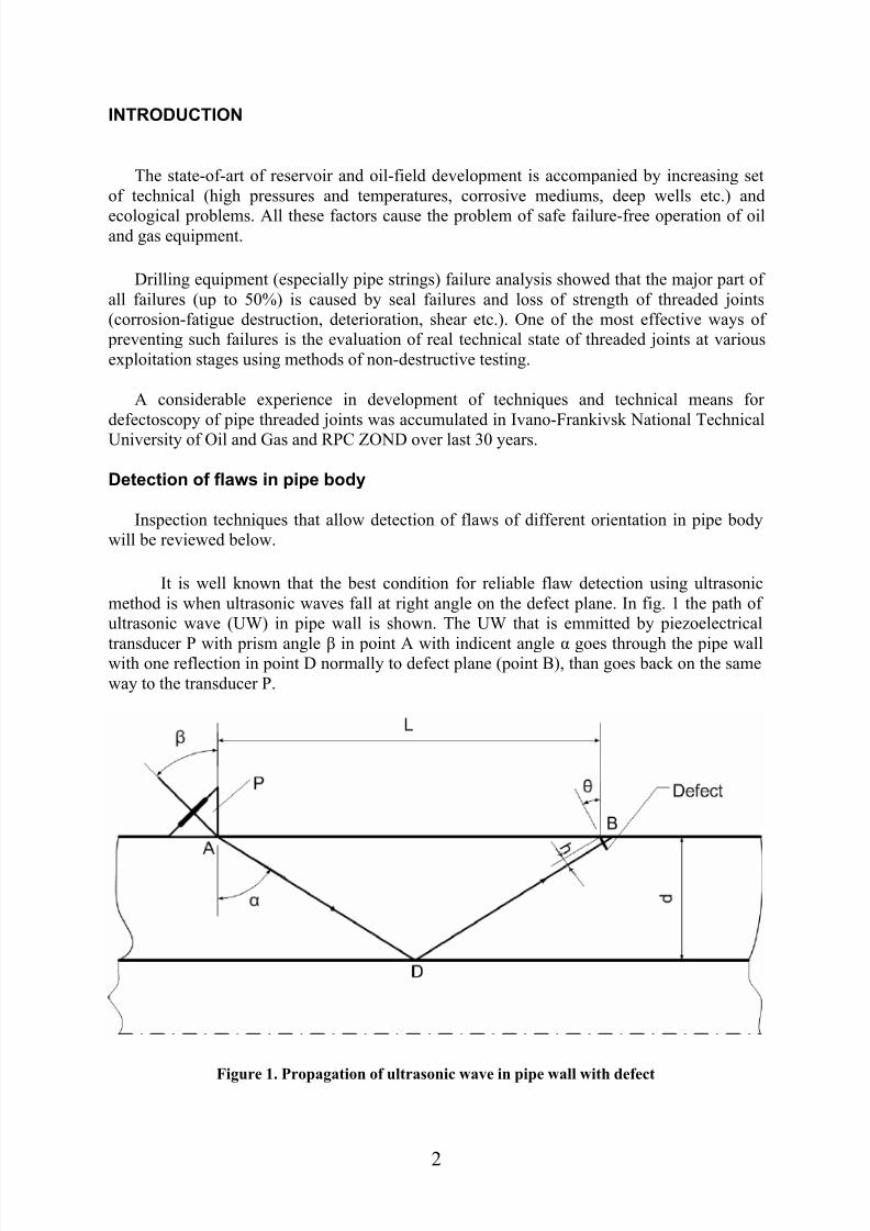
It is well known that the best condition for reliable flaw detection using ultrasonic
method is when ultrasonic waves fall at right angle on the defect plane In fig 1 the path of
ultrasonic wave (UW) in pipe wall is shown The UW that is emmitted by piezoelectrical
transducer P with prism angle β in point A with indicent angle α goes through the pipe wallwith one reflection in point D normally to defect plane (point B) than goes back on the same
way to the transducer P
Figure 1 Propagation of ultrasonic wave in pipe wall with defect
2
8102019 NDT of Drilling Tools
httpslidepdfcomreaderfullndt-of-drilling-tools 310
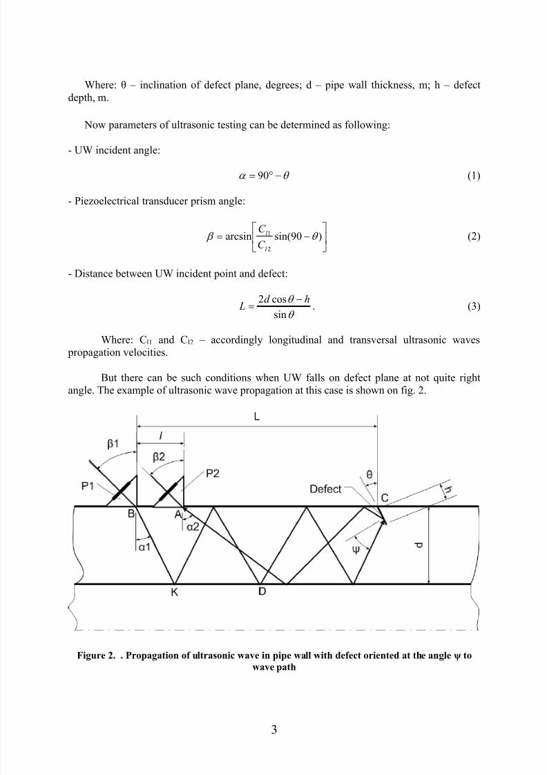
Where θ ndash inclination of defect plane degrees d ndash pipe wall thickness m h ndash defect
depth m
Now parameters of ultrasonic testing can be determined as following
- UW incident angle
θ α minusdeg= 90 (1)
- Piezoelectrical transducer prism angle
minus= )90sin(arcsin
2
1 θ β l
l
C
C (2)
- Distance between UW incident point and defect
θ
θ
sin
cos2 hd L
minus= (3)
Where Cl1 and Cl2 ndash accordingly longitudinal and transversal ultrasonic waves
propagation velocities
But there can be such conditions when UW falls on defect plane at not quite right
angle The example of ultrasonic wave propagation at this case is shown on fig 2
Figure 2 Propagation of ultrasonic wave in pipe wall with defect oriented at the angle ψ to
wave path
3
8102019 NDT of Drilling Tools
httpslidepdfcomreaderfullndt-of-drilling-tools 410
Parameters of ultrasonic inspection now can be determined using following equations
- UW incident angle
)(901 θ α minusminus= (4)
- UW receiving angle
)(902 ψ θ α minus+= (5)
- emmitting piezoelectrical transducer prism angle
+= )cos(arcsin
2
11 ψ θ β
l
l
C
C (6)
- receiving piezoelectrcial transducer prism angle
minus= )cos(arcsin
2
12 ψ θ β
l
l
C
C (7)
- distance between receiving transducer and the defect
)(
2
)sin(
cos
ψ θ ψ θ minusminus
minus=
ctg
d h L (8)
- distance between emmitting and receiving transducers
)cos(
cos
)(
1
)(
2
)(
5
ψ θ ψ θ ψ θ ψ θ minusminus
++
++
+= h
tg ctg ctg
d l (9)
where ψ ndash UW incident angle on defect plane degrees
According to [1] pipes with defects in body with depth more than 3 mm need to be
screened Authors experimentally established [2] that inclination of fatigue defect plane is
near 22deg Now if we define h = 3 mm θ = 22deg using equations (4)-(8) we can determine the
parameters of ultrasonic inspection of drill pipe bodies for detection flaws of transversal
orientation ndash Table 1
4
8102019 NDT of Drilling Tools
httpslidepdfcomreaderfullndt-of-drilling-tools 510
Table 1 Parameters of ultrasonic inspection of drill pipe bodies
Pipe
standard
diameter
mm
Wall
thickness mm
UW incident
angle α
degree
Transducer
prism angle β
degree
Distacnce between
UW incident angle
and defect L mm
7 72660
979 555
932
7 726
9 93289
11
79 555
1138
9 932114
1079 555
1035
9 932127
1179 555
1138
9 932
140 11 79 555 1138
Flaw detection in pipe threaded joints with triangular thread
Pipes with triangular thread are widely used in oil and gas industry [GOST 631-75 API
Spec 5B]
For detection of corrosion-fatigue cracks in threaded joints at early stage of cracking an
ultrasonic method was proposed This method enables flaw detection in threaded pipe joints
when pipes are being made-up (with inner barrel lock or with tool joint box)
To establish regularities of ultrasonic wave propagation in threaded joints of different design
theoretical and experimental investigations were carried out It was shown that ultrasonic waves
propagation in tapered thread needs to be viewed considering its reflection ability from thread
profile which form a set of artificial reflectors with sizes (254 mm) that are bigger than fatigue
cracks (1-15 mm) at the early stage of cracking Fatigue crack front orientation was
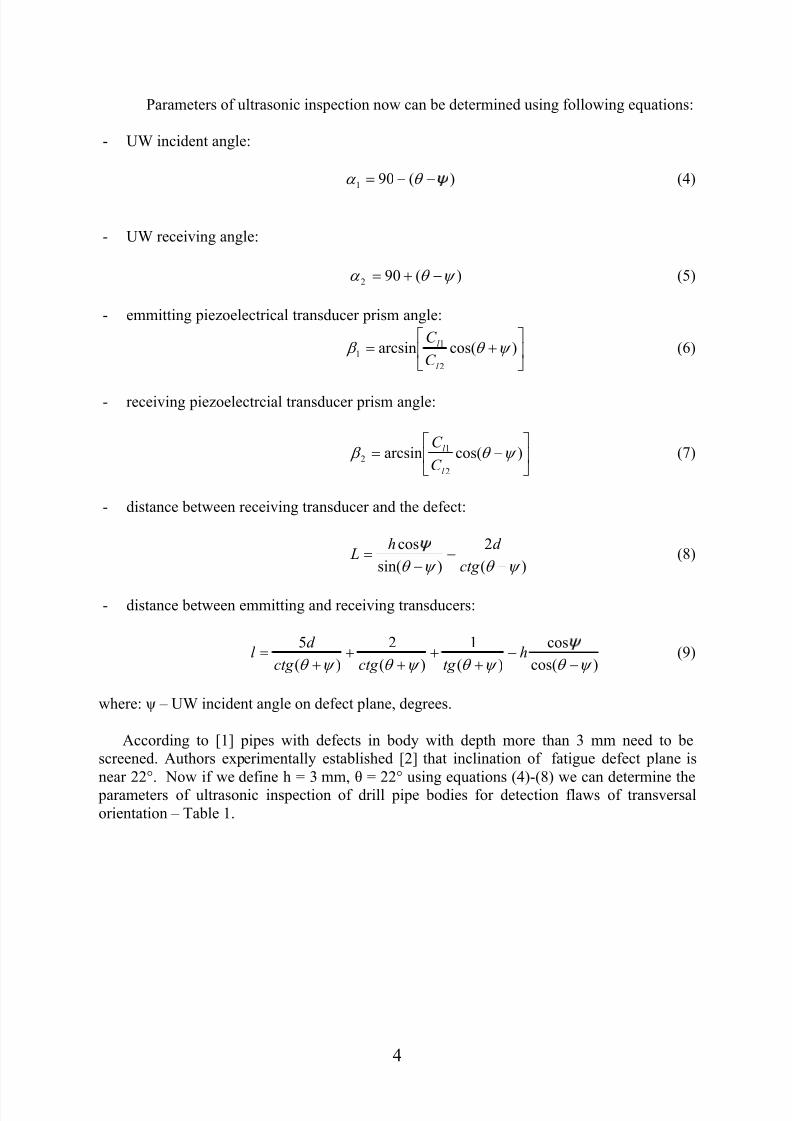
experimentally determined for cracks that propagate in thread vee Effective defectoscopy
techniques (Fig 3) were developed optimal inspection parameters were established as well as
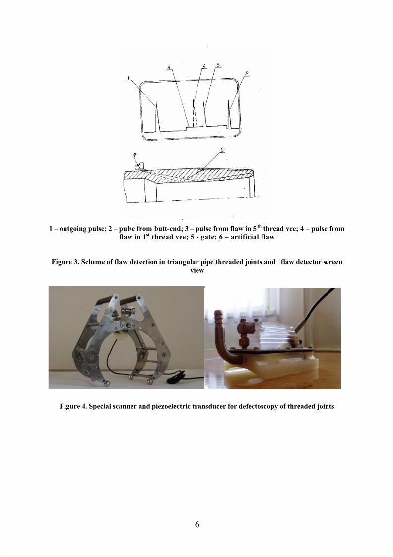
technical means (piezoelectric transducers and scanners) were designed (Fig4) Using these
techniques together with specialized technical means allow to detect flaws in threaded joints
during round-trip directly at the drilling rigs
5
8102019 NDT of Drilling Tools
httpslidepdfcomreaderfullndt-of-drilling-tools 610
1 ndash outgoing pulse 2 ndash pulse from butt-end 3 ndash pulse from flaw in 5th
thread vee 4 ndash pulse from
flaw in 1st thread vee 5 - gate 6 ndash artificial flaw
Figure 3 Scheme of flaw detection in triangular pipe threaded joints and flaw detector screen
view
Figure 4 Special scanner and piezoelectric transducer for defectoscopy of threaded joints
6
8102019 NDT of Drilling Tools
httpslidepdfcomreaderfullndt-of-drilling-tools 710
Defectoscopy of pipe threaded joints with tool-joint thread
A considerable part of oil and gas pipe grades are connected using tool-joint thread
[GOST 5286 API Spec 5B] These are heavy-weight drill pipes (HWDP) and pipes with
enhanced strength and impermeability
Nowadays approaches for defectoscopy of threaded HWDP joints are not effective
because of bigger wall thickness (up to 50 mm) and consequently bigger depth of defect
occurrence
A common defectoscopy technique that is used for threaded joints of HWDP foresees
inspection from end surface of threaded joint This technique requires pipes to be dissambled
and this result in poor efficiency and danger for personnel during round-trip
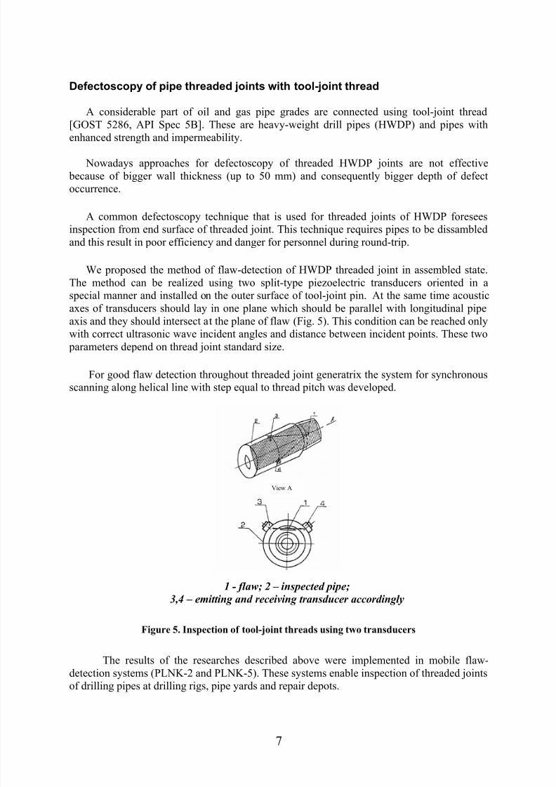
We proposed the method of flaw-detection of HWDP threaded joint in assembled state
The method can be realized using two split-type piezoelectric transducers oriented in a
special manner and installed on the outer surface of tool-joint pin At the same time acoustic
axes of transducers should lay in one plane which should be parallel with longitudinal pipe
axis and they should intersect at the plane of flaw (Fig 5) This condition can be reached only
with correct ultrasonic wave incident angles and distance between incident points These two
parameters depend on thread joint standard size
For good flaw detection throughout threaded joint generatrix the system for synchronous
scanning along helical line with step equal to thread pitch was developed
View A
1 - flaw 2 ndash inspected pipe
34 ndash emitting and receiving transducer accordingly
Figure 5 Inspection of tool-joint threads using two transducers
The results of the researches described above were implemented in mobile flaw-
detection systems (PLNK-2 and PLNK-5) These systems enable inspection of threaded joints
of drilling pipes at drilling rigs pipe yards and repair depots
7
8102019 NDT of Drilling Tools
httpslidepdfcomreaderfullndt-of-drilling-tools 810
Quality inspection of thread stripping (bonding strength and leakproofness)Over the past 20 years heavy industry has been producing drill pipes with threaded joints
of enhanced strength and leakproofness (types Buttress Valurek VAM etc) But usage of
these pipes for first several years resulted in raising number of failures The new problem to
solve was to determine the failure reasons and develop the corresponding methods for quality
inspection In fact the major part of all breakdowns was caused by seal failure and strengthloss in threaded joints The main reasons of threaded joints failures are the following
- abuse of pipe strings
- breakdowns during making-up of joints
- imperfect design of pipes
- absence of technical means for quality inspection of threaded joints during operational
process
We pioneered and implemented new approach for quality rating of threaded joints of
drilling equipment at different stages of their operational period This approach consists not
only in flaw detection in metal (including corrosion-fatigue cracks) but also in measuring the
parameters which determine strength and leakproofness of threaded joint Traditional
methods for threaded joints quality control are based on measurement of indirect parameters
(relative tension torque strength number of screwable elements turns etc) and they donrsquot
allow evaluating the actual technical state of joint after making-up and after some period of
operating After the investigations it was determined that the following characteristics should
be considered as new informational ones
during making-up process point of time when the tension in the most loaded elements
of a threaded joint is near yield stress of the material after making-up and during operational
process magnitude of actual contact area and level of radial deformations in connectedelements
The efficiency of the use of ultrasonic method of non-destructive testing for measuring
parameters that determine threaded joint quality was proved Theoretical and experimental
studies of correlation between operating characteristics of threaded joint and acoustic
parameters were done
The most effective is technique which enables multiple reflection of ultrasonic wave from
surface of contact The use of this technique allows the determination of average and minimal
values of tension without scanning the outer surface of joint what result in higher production
rate and reliability of inspection Figures 6 and 7 show the technique implementation
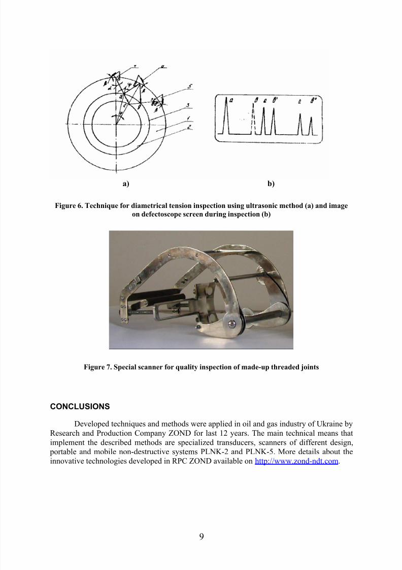
The main point of the technique is that ultrasonic wave hade on the inner surface of the
external member should be determined from equation (10)
]6
sin12
sin41[
6sin
2
nn Rr R
n R
arctg π π
π
α
minusminusminusminus
= (10)
where R r ndash accordingly radiuses of outer surfaces of external and internal members m n ndash
quantity of reflections from inner surface of external member in sector with chord equal to R
8
8102019 NDT of Drilling Tools
httpslidepdfcomreaderfullndt-of-drilling-tools 910
а) b)
Figure 6 Technique for diametrical tension inspection using ultrasonic method (a) and image
on defectoscope screen during inspection (b)
Figure 7 Special scanner for quality inspection of made-up threaded joints
CONCLUSIONS
Developed techniques and methods were applied in oil and gas industry of Ukraine by
Research and Production Company ZOND for last 12 years The main technical means that
implement the described methods are specialized transducers scanners of different design
portable and mobile non-destructive systems PLNK-2 and PLNK-5 More details about the
innovative technologies developed in RPC ZOND available on httpwwwzond-ndtcom
9
8102019 NDT of Drilling Tools
httpslidepdfcomreaderfullndt-of-drilling-tools 1010
REFERENCES CITED
(1) RD-39-013-90 Precept for drill pipes operation ndash Kujbyshev VNIITneft ndash 1990 ndash
228 p (in russian)
(2) Karpash O Krynychnyj P and others Non-destructive testing of drill pipe grades ndashIvano-FrankivskFakel 2001- 380 p (in ukrainian)
ACKNOWLEDGMENTS
The authors wish to acknowledge Scientific and Research Institute of Oil and Gas
Technologies Ivano-Frankivsk (Ukraine) for financial support of this work
10
8102019 NDT of Drilling Tools
httpslidepdfcomreaderfullndt-of-drilling-tools 210
INTRODUCTION
The state-of-art of reservoir and oil-field development is accompanied by increasing set
of technical (high pressures and temperatures corrosive mediums deep wells etc) and
ecological problems All these factors cause the problem of safe failure-free operation of oiland gas equipment
Drilling equipment (especially pipe strings) failure analysis showed that the major part of
all failures (up to 50) is caused by seal failures and loss of strength of threaded joints
(corrosion-fatigue destruction deterioration shear etc) One of the most effective ways of
preventing such failures is the evaluation of real technical state of threaded joints at various
exploitation stages using methods of non-destructive testing
A considerable experience in development of techniques and technical means for
defectoscopy of pipe threaded joints was accumulated in Ivano-Frankivsk National Technical
University of Oil and Gas and RPC ZOND over last 30 years
Detection of flaws in pipe body
Inspection techniques that allow detection of flaws of different orientation in pipe body
will be reviewed below
It is well known that the best condition for reliable flaw detection using ultrasonic
method is when ultrasonic waves fall at right angle on the defect plane In fig 1 the path of
ultrasonic wave (UW) in pipe wall is shown The UW that is emmitted by piezoelectrical
transducer P with prism angle β in point A with indicent angle α goes through the pipe wallwith one reflection in point D normally to defect plane (point B) than goes back on the same
way to the transducer P
Figure 1 Propagation of ultrasonic wave in pipe wall with defect
2
8102019 NDT of Drilling Tools
httpslidepdfcomreaderfullndt-of-drilling-tools 310
Where θ ndash inclination of defect plane degrees d ndash pipe wall thickness m h ndash defect
depth m
Now parameters of ultrasonic testing can be determined as following
- UW incident angle
θ α minusdeg= 90 (1)
- Piezoelectrical transducer prism angle
minus= )90sin(arcsin
2
1 θ β l
l
C
C (2)
- Distance between UW incident point and defect
θ
θ
sin
cos2 hd L
minus= (3)
Where Cl1 and Cl2 ndash accordingly longitudinal and transversal ultrasonic waves
propagation velocities
But there can be such conditions when UW falls on defect plane at not quite right
angle The example of ultrasonic wave propagation at this case is shown on fig 2
Figure 2 Propagation of ultrasonic wave in pipe wall with defect oriented at the angle ψ to
wave path
3
8102019 NDT of Drilling Tools
httpslidepdfcomreaderfullndt-of-drilling-tools 410
Parameters of ultrasonic inspection now can be determined using following equations
- UW incident angle
)(901 θ α minusminus= (4)
- UW receiving angle
)(902 ψ θ α minus+= (5)
- emmitting piezoelectrical transducer prism angle
+= )cos(arcsin
2
11 ψ θ β
l
l
C
C (6)
- receiving piezoelectrcial transducer prism angle
minus= )cos(arcsin
2
12 ψ θ β
l
l
C
C (7)
- distance between receiving transducer and the defect
)(
2
)sin(
cos
ψ θ ψ θ minusminus
minus=
ctg
d h L (8)
- distance between emmitting and receiving transducers
)cos(
cos
)(
1
)(
2
)(
5
ψ θ ψ θ ψ θ ψ θ minusminus
++
++
+= h
tg ctg ctg
d l (9)
where ψ ndash UW incident angle on defect plane degrees
According to [1] pipes with defects in body with depth more than 3 mm need to be
screened Authors experimentally established [2] that inclination of fatigue defect plane is
near 22deg Now if we define h = 3 mm θ = 22deg using equations (4)-(8) we can determine the
parameters of ultrasonic inspection of drill pipe bodies for detection flaws of transversal
orientation ndash Table 1
4
8102019 NDT of Drilling Tools
httpslidepdfcomreaderfullndt-of-drilling-tools 510
Table 1 Parameters of ultrasonic inspection of drill pipe bodies
Pipe
standard
diameter
mm
Wall
thickness mm
UW incident
angle α
degree
Transducer
prism angle β
degree
Distacnce between
UW incident angle
and defect L mm
7 72660
979 555
932
7 726
9 93289
11
79 555
1138
9 932114
1079 555
1035
9 932127
1179 555
1138
9 932
140 11 79 555 1138
Flaw detection in pipe threaded joints with triangular thread
Pipes with triangular thread are widely used in oil and gas industry [GOST 631-75 API
Spec 5B]
For detection of corrosion-fatigue cracks in threaded joints at early stage of cracking an
ultrasonic method was proposed This method enables flaw detection in threaded pipe joints
when pipes are being made-up (with inner barrel lock or with tool joint box)
To establish regularities of ultrasonic wave propagation in threaded joints of different design
theoretical and experimental investigations were carried out It was shown that ultrasonic waves
propagation in tapered thread needs to be viewed considering its reflection ability from thread
profile which form a set of artificial reflectors with sizes (254 mm) that are bigger than fatigue
cracks (1-15 mm) at the early stage of cracking Fatigue crack front orientation was
experimentally determined for cracks that propagate in thread vee Effective defectoscopy
techniques (Fig 3) were developed optimal inspection parameters were established as well as
technical means (piezoelectric transducers and scanners) were designed (Fig4) Using these
techniques together with specialized technical means allow to detect flaws in threaded joints
during round-trip directly at the drilling rigs
5
8102019 NDT of Drilling Tools
httpslidepdfcomreaderfullndt-of-drilling-tools 610
1 ndash outgoing pulse 2 ndash pulse from butt-end 3 ndash pulse from flaw in 5th
thread vee 4 ndash pulse from
flaw in 1st thread vee 5 - gate 6 ndash artificial flaw
Figure 3 Scheme of flaw detection in triangular pipe threaded joints and flaw detector screen
view
Figure 4 Special scanner and piezoelectric transducer for defectoscopy of threaded joints
6
8102019 NDT of Drilling Tools
httpslidepdfcomreaderfullndt-of-drilling-tools 710
Defectoscopy of pipe threaded joints with tool-joint thread
A considerable part of oil and gas pipe grades are connected using tool-joint thread
[GOST 5286 API Spec 5B] These are heavy-weight drill pipes (HWDP) and pipes with
enhanced strength and impermeability
Nowadays approaches for defectoscopy of threaded HWDP joints are not effective
because of bigger wall thickness (up to 50 mm) and consequently bigger depth of defect
occurrence
A common defectoscopy technique that is used for threaded joints of HWDP foresees
inspection from end surface of threaded joint This technique requires pipes to be dissambled
and this result in poor efficiency and danger for personnel during round-trip
We proposed the method of flaw-detection of HWDP threaded joint in assembled state
The method can be realized using two split-type piezoelectric transducers oriented in a
special manner and installed on the outer surface of tool-joint pin At the same time acoustic
axes of transducers should lay in one plane which should be parallel with longitudinal pipe
axis and they should intersect at the plane of flaw (Fig 5) This condition can be reached only
with correct ultrasonic wave incident angles and distance between incident points These two
parameters depend on thread joint standard size
For good flaw detection throughout threaded joint generatrix the system for synchronous
scanning along helical line with step equal to thread pitch was developed
View A
1 - flaw 2 ndash inspected pipe
34 ndash emitting and receiving transducer accordingly
Figure 5 Inspection of tool-joint threads using two transducers
The results of the researches described above were implemented in mobile flaw-
detection systems (PLNK-2 and PLNK-5) These systems enable inspection of threaded joints
of drilling pipes at drilling rigs pipe yards and repair depots
7
8102019 NDT of Drilling Tools
httpslidepdfcomreaderfullndt-of-drilling-tools 810
Quality inspection of thread stripping (bonding strength and leakproofness)Over the past 20 years heavy industry has been producing drill pipes with threaded joints
of enhanced strength and leakproofness (types Buttress Valurek VAM etc) But usage of
these pipes for first several years resulted in raising number of failures The new problem to
solve was to determine the failure reasons and develop the corresponding methods for quality
inspection In fact the major part of all breakdowns was caused by seal failure and strengthloss in threaded joints The main reasons of threaded joints failures are the following
- abuse of pipe strings
- breakdowns during making-up of joints
- imperfect design of pipes
- absence of technical means for quality inspection of threaded joints during operational
process
We pioneered and implemented new approach for quality rating of threaded joints of
drilling equipment at different stages of their operational period This approach consists not
only in flaw detection in metal (including corrosion-fatigue cracks) but also in measuring the
parameters which determine strength and leakproofness of threaded joint Traditional
methods for threaded joints quality control are based on measurement of indirect parameters
(relative tension torque strength number of screwable elements turns etc) and they donrsquot
allow evaluating the actual technical state of joint after making-up and after some period of
operating After the investigations it was determined that the following characteristics should
be considered as new informational ones
during making-up process point of time when the tension in the most loaded elements
of a threaded joint is near yield stress of the material after making-up and during operational
process magnitude of actual contact area and level of radial deformations in connectedelements
The efficiency of the use of ultrasonic method of non-destructive testing for measuring
parameters that determine threaded joint quality was proved Theoretical and experimental
studies of correlation between operating characteristics of threaded joint and acoustic
parameters were done
The most effective is technique which enables multiple reflection of ultrasonic wave from
surface of contact The use of this technique allows the determination of average and minimal
values of tension without scanning the outer surface of joint what result in higher production
rate and reliability of inspection Figures 6 and 7 show the technique implementation
The main point of the technique is that ultrasonic wave hade on the inner surface of the
external member should be determined from equation (10)
]6
sin12
sin41[
6sin
2
nn Rr R
n R
arctg π π
π
α
minusminusminusminus
= (10)
where R r ndash accordingly radiuses of outer surfaces of external and internal members m n ndash
quantity of reflections from inner surface of external member in sector with chord equal to R
8
8102019 NDT of Drilling Tools
httpslidepdfcomreaderfullndt-of-drilling-tools 910
а) b)
Figure 6 Technique for diametrical tension inspection using ultrasonic method (a) and image
on defectoscope screen during inspection (b)
Figure 7 Special scanner for quality inspection of made-up threaded joints
CONCLUSIONS
Developed techniques and methods were applied in oil and gas industry of Ukraine by
Research and Production Company ZOND for last 12 years The main technical means that
implement the described methods are specialized transducers scanners of different design
portable and mobile non-destructive systems PLNK-2 and PLNK-5 More details about the
innovative technologies developed in RPC ZOND available on httpwwwzond-ndtcom
9
8102019 NDT of Drilling Tools
httpslidepdfcomreaderfullndt-of-drilling-tools 1010
REFERENCES CITED
(1) RD-39-013-90 Precept for drill pipes operation ndash Kujbyshev VNIITneft ndash 1990 ndash
228 p (in russian)
(2) Karpash O Krynychnyj P and others Non-destructive testing of drill pipe grades ndashIvano-FrankivskFakel 2001- 380 p (in ukrainian)
ACKNOWLEDGMENTS
The authors wish to acknowledge Scientific and Research Institute of Oil and Gas
Technologies Ivano-Frankivsk (Ukraine) for financial support of this work
10
8102019 NDT of Drilling Tools
httpslidepdfcomreaderfullndt-of-drilling-tools 410
Parameters of ultrasonic inspection now can be determined using following equations
- UW incident angle
)(901 θ α minusminus= (4)
- UW receiving angle
)(902 ψ θ α minus+= (5)
- emmitting piezoelectrical transducer prism angle
+= )cos(arcsin
2
11 ψ θ β
l
l
C
C (6)
- receiving piezoelectrcial transducer prism angle
minus= )cos(arcsin
2
12 ψ θ β
l
l
C
C (7)
- distance between receiving transducer and the defect
)(
2
)sin(
cos
ψ θ ψ θ minusminus
minus=
ctg
d h L (8)
- distance between emmitting and receiving transducers
)cos(
cos
)(
1
)(
2
)(
5
ψ θ ψ θ ψ θ ψ θ minusminus
++
++
+= h
tg ctg ctg
d l (9)
where ψ ndash UW incident angle on defect plane degrees
According to [1] pipes with defects in body with depth more than 3 mm need to be
screened Authors experimentally established [2] that inclination of fatigue defect plane is
near 22deg Now if we define h = 3 mm θ = 22deg using equations (4)-(8) we can determine the
parameters of ultrasonic inspection of drill pipe bodies for detection flaws of transversal
orientation ndash Table 1
4
8102019 NDT of Drilling Tools
httpslidepdfcomreaderfullndt-of-drilling-tools 510
Table 1 Parameters of ultrasonic inspection of drill pipe bodies
Pipe
standard
diameter
mm
Wall
thickness mm
UW incident
angle α
degree
Transducer
prism angle β
degree
Distacnce between
UW incident angle
and defect L mm
7 72660
979 555
932
7 726
9 93289
11
79 555
1138
9 932114
1079 555
1035
9 932127
1179 555
1138
9 932
140 11 79 555 1138
Flaw detection in pipe threaded joints with triangular thread
Pipes with triangular thread are widely used in oil and gas industry [GOST 631-75 API
Spec 5B]
For detection of corrosion-fatigue cracks in threaded joints at early stage of cracking an
ultrasonic method was proposed This method enables flaw detection in threaded pipe joints
when pipes are being made-up (with inner barrel lock or with tool joint box)
To establish regularities of ultrasonic wave propagation in threaded joints of different design
theoretical and experimental investigations were carried out It was shown that ultrasonic waves
propagation in tapered thread needs to be viewed considering its reflection ability from thread
profile which form a set of artificial reflectors with sizes (254 mm) that are bigger than fatigue
cracks (1-15 mm) at the early stage of cracking Fatigue crack front orientation was
experimentally determined for cracks that propagate in thread vee Effective defectoscopy
techniques (Fig 3) were developed optimal inspection parameters were established as well as
technical means (piezoelectric transducers and scanners) were designed (Fig4) Using these
techniques together with specialized technical means allow to detect flaws in threaded joints
during round-trip directly at the drilling rigs
5
8102019 NDT of Drilling Tools
httpslidepdfcomreaderfullndt-of-drilling-tools 610
1 ndash outgoing pulse 2 ndash pulse from butt-end 3 ndash pulse from flaw in 5th
thread vee 4 ndash pulse from
flaw in 1st thread vee 5 - gate 6 ndash artificial flaw
Figure 3 Scheme of flaw detection in triangular pipe threaded joints and flaw detector screen
view
Figure 4 Special scanner and piezoelectric transducer for defectoscopy of threaded joints
6
8102019 NDT of Drilling Tools
httpslidepdfcomreaderfullndt-of-drilling-tools 710
Defectoscopy of pipe threaded joints with tool-joint thread
A considerable part of oil and gas pipe grades are connected using tool-joint thread
[GOST 5286 API Spec 5B] These are heavy-weight drill pipes (HWDP) and pipes with
enhanced strength and impermeability
Nowadays approaches for defectoscopy of threaded HWDP joints are not effective
because of bigger wall thickness (up to 50 mm) and consequently bigger depth of defect
occurrence
A common defectoscopy technique that is used for threaded joints of HWDP foresees
inspection from end surface of threaded joint This technique requires pipes to be dissambled
and this result in poor efficiency and danger for personnel during round-trip
We proposed the method of flaw-detection of HWDP threaded joint in assembled state
The method can be realized using two split-type piezoelectric transducers oriented in a
special manner and installed on the outer surface of tool-joint pin At the same time acoustic
axes of transducers should lay in one plane which should be parallel with longitudinal pipe
axis and they should intersect at the plane of flaw (Fig 5) This condition can be reached only
with correct ultrasonic wave incident angles and distance between incident points These two
parameters depend on thread joint standard size
For good flaw detection throughout threaded joint generatrix the system for synchronous
scanning along helical line with step equal to thread pitch was developed
View A
1 - flaw 2 ndash inspected pipe
34 ndash emitting and receiving transducer accordingly
Figure 5 Inspection of tool-joint threads using two transducers
The results of the researches described above were implemented in mobile flaw-
detection systems (PLNK-2 and PLNK-5) These systems enable inspection of threaded joints
of drilling pipes at drilling rigs pipe yards and repair depots
7
8102019 NDT of Drilling Tools
httpslidepdfcomreaderfullndt-of-drilling-tools 810
Quality inspection of thread stripping (bonding strength and leakproofness)Over the past 20 years heavy industry has been producing drill pipes with threaded joints
of enhanced strength and leakproofness (types Buttress Valurek VAM etc) But usage of
these pipes for first several years resulted in raising number of failures The new problem to
solve was to determine the failure reasons and develop the corresponding methods for quality
inspection In fact the major part of all breakdowns was caused by seal failure and strengthloss in threaded joints The main reasons of threaded joints failures are the following
- abuse of pipe strings
- breakdowns during making-up of joints
- imperfect design of pipes
- absence of technical means for quality inspection of threaded joints during operational
process
We pioneered and implemented new approach for quality rating of threaded joints of
drilling equipment at different stages of their operational period This approach consists not
only in flaw detection in metal (including corrosion-fatigue cracks) but also in measuring the
parameters which determine strength and leakproofness of threaded joint Traditional
methods for threaded joints quality control are based on measurement of indirect parameters
(relative tension torque strength number of screwable elements turns etc) and they donrsquot
allow evaluating the actual technical state of joint after making-up and after some period of
operating After the investigations it was determined that the following characteristics should
be considered as new informational ones
during making-up process point of time when the tension in the most loaded elements
of a threaded joint is near yield stress of the material after making-up and during operational
process magnitude of actual contact area and level of radial deformations in connectedelements
The efficiency of the use of ultrasonic method of non-destructive testing for measuring
parameters that determine threaded joint quality was proved Theoretical and experimental
studies of correlation between operating characteristics of threaded joint and acoustic
parameters were done
The most effective is technique which enables multiple reflection of ultrasonic wave from
surface of contact The use of this technique allows the determination of average and minimal
values of tension without scanning the outer surface of joint what result in higher production
rate and reliability of inspection Figures 6 and 7 show the technique implementation
The main point of the technique is that ultrasonic wave hade on the inner surface of the
external member should be determined from equation (10)
]6
sin12
sin41[
6sin
2
nn Rr R
n R
arctg π π
π
α
minusminusminusminus
= (10)
where R r ndash accordingly radiuses of outer surfaces of external and internal members m n ndash
quantity of reflections from inner surface of external member in sector with chord equal to R
8
8102019 NDT of Drilling Tools
httpslidepdfcomreaderfullndt-of-drilling-tools 910
а) b)
Figure 6 Technique for diametrical tension inspection using ultrasonic method (a) and image
on defectoscope screen during inspection (b)
Figure 7 Special scanner for quality inspection of made-up threaded joints
CONCLUSIONS
Developed techniques and methods were applied in oil and gas industry of Ukraine by
Research and Production Company ZOND for last 12 years The main technical means that
implement the described methods are specialized transducers scanners of different design
portable and mobile non-destructive systems PLNK-2 and PLNK-5 More details about the
innovative technologies developed in RPC ZOND available on httpwwwzond-ndtcom
9
8102019 NDT of Drilling Tools
httpslidepdfcomreaderfullndt-of-drilling-tools 1010
REFERENCES CITED
(1) RD-39-013-90 Precept for drill pipes operation ndash Kujbyshev VNIITneft ndash 1990 ndash
228 p (in russian)
(2) Karpash O Krynychnyj P and others Non-destructive testing of drill pipe grades ndashIvano-FrankivskFakel 2001- 380 p (in ukrainian)
ACKNOWLEDGMENTS
The authors wish to acknowledge Scientific and Research Institute of Oil and Gas
Technologies Ivano-Frankivsk (Ukraine) for financial support of this work
10

8102019 NDT of Drilling Tools
httpslidepdfcomreaderfullndt-of-drilling-tools 510
Table 1 Parameters of ultrasonic inspection of drill pipe bodies
Pipe
standard
diameter
mm
Wall
thickness mm
UW incident
angle α
degree
Transducer
prism angle β
degree
Distacnce between
UW incident angle
and defect L mm
7 72660
979 555
932
7 726
9 93289
11
79 555
1138
9 932114
1079 555
1035
9 932127
1179 555
1138
9 932
140 11 79 555 1138
Flaw detection in pipe threaded joints with triangular thread
Pipes with triangular thread are widely used in oil and gas industry [GOST 631-75 API
Spec 5B]
For detection of corrosion-fatigue cracks in threaded joints at early stage of cracking an
ultrasonic method was proposed This method enables flaw detection in threaded pipe joints
when pipes are being made-up (with inner barrel lock or with tool joint box)
To establish regularities of ultrasonic wave propagation in threaded joints of different design
theoretical and experimental investigations were carried out It was shown that ultrasonic waves
propagation in tapered thread needs to be viewed considering its reflection ability from thread
profile which form a set of artificial reflectors with sizes (254 mm) that are bigger than fatigue
cracks (1-15 mm) at the early stage of cracking Fatigue crack front orientation was
experimentally determined for cracks that propagate in thread vee Effective defectoscopy
techniques (Fig 3) were developed optimal inspection parameters were established as well as
technical means (piezoelectric transducers and scanners) were designed (Fig4) Using these
techniques together with specialized technical means allow to detect flaws in threaded joints
during round-trip directly at the drilling rigs
5
8102019 NDT of Drilling Tools
httpslidepdfcomreaderfullndt-of-drilling-tools 610
1 ndash outgoing pulse 2 ndash pulse from butt-end 3 ndash pulse from flaw in 5th
thread vee 4 ndash pulse from
flaw in 1st thread vee 5 - gate 6 ndash artificial flaw
Figure 3 Scheme of flaw detection in triangular pipe threaded joints and flaw detector screen
view
Figure 4 Special scanner and piezoelectric transducer for defectoscopy of threaded joints
6
8102019 NDT of Drilling Tools
httpslidepdfcomreaderfullndt-of-drilling-tools 710
Defectoscopy of pipe threaded joints with tool-joint thread
A considerable part of oil and gas pipe grades are connected using tool-joint thread
[GOST 5286 API Spec 5B] These are heavy-weight drill pipes (HWDP) and pipes with
enhanced strength and impermeability
Nowadays approaches for defectoscopy of threaded HWDP joints are not effective
because of bigger wall thickness (up to 50 mm) and consequently bigger depth of defect
occurrence
A common defectoscopy technique that is used for threaded joints of HWDP foresees
inspection from end surface of threaded joint This technique requires pipes to be dissambled
and this result in poor efficiency and danger for personnel during round-trip
We proposed the method of flaw-detection of HWDP threaded joint in assembled state
The method can be realized using two split-type piezoelectric transducers oriented in a
special manner and installed on the outer surface of tool-joint pin At the same time acoustic
axes of transducers should lay in one plane which should be parallel with longitudinal pipe
axis and they should intersect at the plane of flaw (Fig 5) This condition can be reached only
with correct ultrasonic wave incident angles and distance between incident points These two
parameters depend on thread joint standard size
For good flaw detection throughout threaded joint generatrix the system for synchronous
scanning along helical line with step equal to thread pitch was developed
View A
1 - flaw 2 ndash inspected pipe
34 ndash emitting and receiving transducer accordingly
Figure 5 Inspection of tool-joint threads using two transducers
The results of the researches described above were implemented in mobile flaw-
detection systems (PLNK-2 and PLNK-5) These systems enable inspection of threaded joints
of drilling pipes at drilling rigs pipe yards and repair depots
7
8102019 NDT of Drilling Tools
httpslidepdfcomreaderfullndt-of-drilling-tools 810
Quality inspection of thread stripping (bonding strength and leakproofness)Over the past 20 years heavy industry has been producing drill pipes with threaded joints
of enhanced strength and leakproofness (types Buttress Valurek VAM etc) But usage of
these pipes for first several years resulted in raising number of failures The new problem to
solve was to determine the failure reasons and develop the corresponding methods for quality
inspection In fact the major part of all breakdowns was caused by seal failure and strengthloss in threaded joints The main reasons of threaded joints failures are the following
- abuse of pipe strings
- breakdowns during making-up of joints
- imperfect design of pipes
- absence of technical means for quality inspection of threaded joints during operational
process
We pioneered and implemented new approach for quality rating of threaded joints of
drilling equipment at different stages of their operational period This approach consists not
only in flaw detection in metal (including corrosion-fatigue cracks) but also in measuring the
parameters which determine strength and leakproofness of threaded joint Traditional
methods for threaded joints quality control are based on measurement of indirect parameters
(relative tension torque strength number of screwable elements turns etc) and they donrsquot
allow evaluating the actual technical state of joint after making-up and after some period of
operating After the investigations it was determined that the following characteristics should
be considered as new informational ones
during making-up process point of time when the tension in the most loaded elements
of a threaded joint is near yield stress of the material after making-up and during operational
process magnitude of actual contact area and level of radial deformations in connectedelements
The efficiency of the use of ultrasonic method of non-destructive testing for measuring
parameters that determine threaded joint quality was proved Theoretical and experimental
studies of correlation between operating characteristics of threaded joint and acoustic
parameters were done
The most effective is technique which enables multiple reflection of ultrasonic wave from
surface of contact The use of this technique allows the determination of average and minimal
values of tension without scanning the outer surface of joint what result in higher production
rate and reliability of inspection Figures 6 and 7 show the technique implementation
The main point of the technique is that ultrasonic wave hade on the inner surface of the
external member should be determined from equation (10)
]6
sin12
sin41[
6sin
2
nn Rr R
n R
arctg π π
π
α
minusminusminusminus
= (10)
where R r ndash accordingly radiuses of outer surfaces of external and internal members m n ndash
quantity of reflections from inner surface of external member in sector with chord equal to R
8
8102019 NDT of Drilling Tools
httpslidepdfcomreaderfullndt-of-drilling-tools 910
а) b)
Figure 6 Technique for diametrical tension inspection using ultrasonic method (a) and image
on defectoscope screen during inspection (b)
Figure 7 Special scanner for quality inspection of made-up threaded joints
CONCLUSIONS
Developed techniques and methods were applied in oil and gas industry of Ukraine by
Research and Production Company ZOND for last 12 years The main technical means that
implement the described methods are specialized transducers scanners of different design
portable and mobile non-destructive systems PLNK-2 and PLNK-5 More details about the
innovative technologies developed in RPC ZOND available on httpwwwzond-ndtcom
9
8102019 NDT of Drilling Tools
httpslidepdfcomreaderfullndt-of-drilling-tools 1010
REFERENCES CITED
(1) RD-39-013-90 Precept for drill pipes operation ndash Kujbyshev VNIITneft ndash 1990 ndash
228 p (in russian)
(2) Karpash O Krynychnyj P and others Non-destructive testing of drill pipe grades ndashIvano-FrankivskFakel 2001- 380 p (in ukrainian)
ACKNOWLEDGMENTS
The authors wish to acknowledge Scientific and Research Institute of Oil and Gas
Technologies Ivano-Frankivsk (Ukraine) for financial support of this work
10
8102019 NDT of Drilling Tools
httpslidepdfcomreaderfullndt-of-drilling-tools 910
а) b)
Figure 6 Technique for diametrical tension inspection using ultrasonic method (a) and image
on defectoscope screen during inspection (b)
Figure 7 Special scanner for quality inspection of made-up threaded joints
CONCLUSIONS
Developed techniques and methods were applied in oil and gas industry of Ukraine by
Research and Production Company ZOND for last 12 years The main technical means that
implement the described methods are specialized transducers scanners of different design
portable and mobile non-destructive systems PLNK-2 and PLNK-5 More details about the
innovative technologies developed in RPC ZOND available on httpwwwzond-ndtcom
9
8102019 NDT of Drilling Tools
httpslidepdfcomreaderfullndt-of-drilling-tools 1010
REFERENCES CITED
(1) RD-39-013-90 Precept for drill pipes operation ndash Kujbyshev VNIITneft ndash 1990 ndash
228 p (in russian)
(2) Karpash O Krynychnyj P and others Non-destructive testing of drill pipe grades ndashIvano-FrankivskFakel 2001- 380 p (in ukrainian)
ACKNOWLEDGMENTS
The authors wish to acknowledge Scientific and Research Institute of Oil and Gas
Technologies Ivano-Frankivsk (Ukraine) for financial support of this work
10
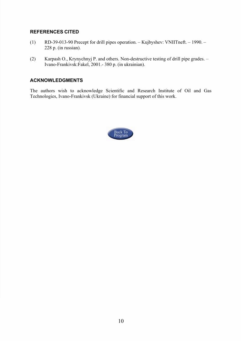