771
†To whom correspondence should be addressed.
E-mail: [email protected]
Korean J. Chem. Eng., 30(4), 771-786 (2013)DOI: 10.1007/s11814-013-0033-8
INVITED REVIEW PAPER
Natural gas hydrate as a potential energy resource: From occurrence to production
Jiwoong Seol and Huen Lee†
Department of Chemical and Biomolecular Engineering (BK21 program) and Graduate School of EEWS, KAIST,335, Gwahangno, Yuseong-gu, Daejeon 305-701, Korea
(Received 19 January 2013 • accepted 26 February 2013)
Abstract−Natural gas hydrate reservoirs have been strongly suggested as a potential energy resource. However, this
potential is expected to be limited by geological factors, reservoir properties, and phase-equilibria considerations. Ac-
cordingly, sufficient understanding and accurate analyses for the complex surroundings in a natural gas hydrate system
have to occur before methane recovery. In this paper, we discuss the formation and structure patterns of global natural
gas hydrate, including the origins of hydrocarbon, crystal structures, and unique structure transition. We also summarize
two important anomalies related to methane occupancy and chlorinity which were revealed very recently. Further-
more, we review the geological and chemical surroundings of the shallow hydrate deposits, the so-called brine patch
discovered in the Cascadia Margin and Ulleung Basin, which are significantly related to tectonic conduits for methane
gas and positive chlorinity.
Key words: Natural Gas Hydrate, Methane Occupancy, Chlorinity, Shallow Hydrate, Ulleung Basin
INTRODUCTION
It is generally assumed that oceanic gas hydrates contain a hugevolume of natural gases. The most widely cited estimate of naturalgases in global hydrates is 21×1015 m3 of methane at STP (corre-sponding to about 10 Tt of methane carbon), which is proposed asa consensus value [1]. This large gas hydrate reservoir is furthersuggested as a potential (1) factor in global climate change, (2) sub-marine geo-hazard, and (3) energy resource [2]. Assessments of gashydrate as an energy source have often been optimistic, based onworldwide occurrence in continental margins and the high methanecontent of natural gas hydrate. For energy recovery from naturalgas hydrate, numerous studies have been done, such as thermody-namic analysis of methane hydrate [3,4] and recovery processesusing unique swapping patterns induced by external CO2 and CO2/N2 gas [5-7], and the results seem to be attractive. However, the im-portant problem is that the real recovery processes are expected tobe necessarily limited by geological factors, reservoir properties andphase-equilibria considerations. For the past decade, the regionalgas hydrate stability zone (RGHSZ) has been found to have a verycomplicated geometry with significant variability due to lateral andvertical changes in pore water salinity and heat flow. Furthermore,the gas hydrate occurrence is noticed to be controlled by complexinteraction of unique factors, such as temperature, pressure, salin-ity, and geochemical regime. Accordingly, sufficient understandingand accurate analyses for the complex surroundings in natural sys-tem have to occur before methane recovery.
Boswell and Collett suggested a gas hydrate resource pyramidthat is commonly used to display the relative amount and productivityof different elements arranged with the most promising resourcesat the top and most challenging at the base [8]. Instead of Arctic
sandstones at the top of the pyramid, oceanic gas hydrates generallycan be classified into four types. The first one, deep-water sand-stones, includes moderate-to-high concentrations of gas hydratesthat may be challenged by the high costs of gas production due tothe depth. The second one is the gas hydrate deposits generally foundencaged in non-sandstones including fractured fine-grained mudsand shales. The production of methane from this type of deposit hasbeen considered to be technically problematic at the present stage.The third one is deep-seated hydrate disseminated in the RGHSZ,above the base of the gas hydrate stability zone (BGHSZ). Althoughthis type of deposit hosts the largest fraction of total gas hydrateresources, this is at the very base of the resource pyramid becauseof poor permeability through fine-grained sediment and low satu-rations of gas hydrate (~10% or less) [9,10]. The concept of gasproduction from fine-grained sediments using gas-driving fracturinginduced by thermal stimulation was suggested [10]. Santamarinaand Jang reported that thermally dissociated gas with extensive vol-ume can generate fractures and develop high permeability paths thatcan facilitate gas production in fine-grained sediments. However,most of the fine-grained gas hydrate systems are considered to havevery poor reservoir potential [11]. The last and special one is locally-concentrated massive hydrate formed in shallow depth near the seaf-loor. Recently, it has been continuously discovered worldwide, butthe accurate amount of this reservoir is unknown yet. It is particu-larly known to be associated with geological conduits which act asconduits for gases and fluids, for example, Horizon A at the south-ern summit of Hydrate Ridge, Cascadia Margin [12], and the seis-mic chimneys in the Ulleung Basin offshore Korea [13,14]. Shallowhydrate deposits associated with cold vents have been also reportedin the Gulf of Mexico [15], the Nankai Trough [16], the CascadiaMargin [12,17,18], and the Ulleung Basin [19], where tectonic ordiapiric faults provide fluid transport path. In several regions of near-seafloor hydrate, a unique signature of significantly enriched chlo-rinities (positive anomalies) was also detected.
772 J. Seol and H. Lee
April, 2013
In this paper, we discuss the formation and structure patterns ofglobal natural gas hydrate including the origins of hydrocarbon, crys-tal structures, and unique structure transition. We also summarizetwo important anomalies related to methane occupancy and chlo-rinity, which were revealed very recently. Furthermore, we reviewthe geological and chemical surroundings of the shallow hydratedeposits, the so-called brine patch discovered in the Cascadia Mar-gin and Ulleung Basin, which are significantly related to tectonicconduits for methane gas and positive chlorinity.
FORMATION AND STRUCTURE TRANSITION
PATTERNS OF NATURAL GAS HYDRATE
1. Biogenic and Thermogenic Hydrocarbon Sources
Hydrocarbon gases in natural gas hydrate are divided into twotypes according to their origin, biogenic and thermogenic hydrocar-bons. The molecular composition (C1/C2+) of hydrocarbon gases ingas hydrate samples, coupled with measurements of carbon iso-tope of methane (δ
13
CC1), provide a basis for interpreting the originof this gas. They are defined as follows:
(1)
(2)
In most of the methane hydrate samples, methane has carbon-isotopic composition lighter than −60‰ (δ
13
CC1<−60‰), suggest-ing that the methane is mainly of microbial origin. Isotopically lighterthan −70‰ has not often been found in natural gas hydrate. Micro-bial methane in methane hydrate may have either been generatedin place, have migrated only short distances, or been recycled duringthe concomitant process of hydrate formation and dissociation ac-companying sediment [20]. This biogenic methane likely resultsfrom bacterial methanogenic processes, taking place in shallow sedi-ment below the sulfate reduction zone, in which CO2 is reduced tomethane. The net reaction is represented by,
CO2+8 H++8e−→CH4+2H2O
The anaerobic reaction for consumption of methane and sulfate re-sulting in the production of carbonate in the sulfate reduction zoneoccurs as
CH4+SO42−→CO3
2−+H2S+H2O
To much lesser extent, especially in oceanic sediment, acetate fromorganic matter is converted to methane by fermentation reactions.
CH3COOH→CH4+CO2
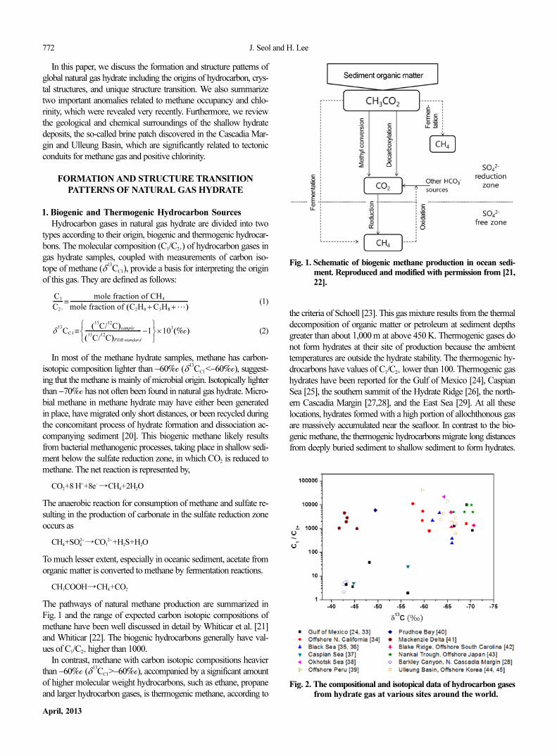
The pathways of natural methane production are summarized inFig. 1 and the range of expected carbon isotopic compositions ofmethane have been well discussed in detail by Whiticar et al. [21]and Whiticar [22]. The biogenic hydrocarbons generally have val-ues of C1/C2+ higher than 1000.
In contrast, methane with carbon isotopic compositions heavierthan −60‰ (δ
13
CC1>−60‰), accompanied by a significant amountof higher molecular weight hydrocarbons, such as ethane, propaneand larger hydrocarbon gases, is thermogenic methane, according to
the criteria of Schoell [23]. This gas mixture results from the thermaldecomposition of organic matter or petroleum at sediment depthsgreater than about 1,000 m at above 450 K. Thermogenic gases donot form hydrates at their site of production because the ambienttemperatures are outside the hydrate stability. The thermogenic hy-drocarbons have values of C1/C2+ lower than 100. Thermogenic gashydrates have been reported for the Gulf of Mexico [24], CaspianSea [25], the southern summit of the Hydrate Ridge [26], the north-ern Cascadia Margin [27,28], and the East Sea [29]. At all theselocations, hydrates formed with a high portion of allochthonous gasare massively accumulated near the seafloor. In contrast to the bio-genic methane, the thermogenic hydrocarbons migrate long distancesfrom deeply buried sediment to shallow sediment to form hydrates.
C1
C2+
-------mole fraction of CH4
mole fraction of C2H6 + C3H8 +
…( )------------------------------------------------------------------------------------≡
δ
13
CC1
C13
/ C12( )sample
C13
/ C12( )PDB standard
---------------------------------------- −1⎩ ⎭⎨ ⎬⎧ ⎫
≡ 103
‰( )×
Fig. 1. Schematic of biogenic methane production in ocean sedi-ment. Reproduced and modified with permission from [21,22].
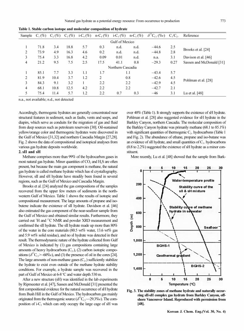
Fig. 2. The compositional and isotopical data of hydrocarbon gasesfrom hydrate gas at various sites around the world.
Natural gas hydrate as a potential energy resource: From occurrence to production 773
Korean J. Chem. Eng.(Vol. 30, No. 4)
Accordingly, thermogenic hydrates are generally concentrated nearstructural features in sediment, such as faults, vents and seeps, anddiapirs, which serve as conduits for the migration of gas and fluidfrom deep sources such as petroleum reservoirs [30]. Oil-sustainedyellow/orange color and thermogenic hydrates were discovered inthe Gulf of Mexico [31,32] and northern Cascadia Margin [27,28].Fig. 2 shows the data of compositional and isotopical analyses fromvarious gas hydrate deposits worldwide.2. sII and sH
Methane comprises more than 99% of the hydrocarbon gases inmost natural gas hydrate. Minor quantities of CO2 and H2S are oftenpresent, but because the main gas component is methane, the naturalgas hydrate is called methane hydrate which has sI crystallography.However, sII and sH hydrate have steadily been found in severalregions, such as the Gulf of Mexico and Cascadia Margin.
Brooks et al. [24] analyzed the gas compositions of the samplesrecovered from the upper few meters of sediments in the north-western Gulf of Mexico. Table 1 shows the results of isotopic andcompositional measurement. The large amounts of propane and iso-butene indicate the existence of sII hydrate. Davidson et al. [46]also estimated the gas component of the near-seafloor sample fromthe Gulf of Mexico and obtained similar results. Furthermore, theycarried out 1H and 13C NMR and powder XRD measurement andconfirmed the sII hydrate. The sII hydrate made up more than 80%of the water in the core materials (80.5 wt% water, 13.6 wt% gasand 5.9 wt% solid residue), and no sI hydrate was detected in theirresult. The thermodynamic nature of the hydrate collected from Gulfof Mexico is indicated by (1) gas compositions containing largeamounts of heavy hydrocarbons (C2+), (2) carbon isotopic compo-sitions (δ
13
CC1>−60‰), and (3) the presence of oil in the cores [24].The large amounts of non-methane gases (C2+) sufficiently stabilizethe hydrate to exist even outside of the methane hydrate stabilityconditions. For example, a hydrate sample was recovered in thepart of Gulf of Mexico at 6-8 oC and water depth 530 m.
After a new structure (sH) was identified in the lab experimentsby Ripmeester et al. [47], Sassen and McDonald [31] presented thefirst compositional evidence for the natural occurrence of sH hydratefrom Bush Hill in the Gulf of Mexico. The hydrocarbon gas mainlyoriginated from the thermogenic source (δ
13
CC1~−29.3‰). The com-position of i-C5 which can only occupy the large cage of sH was
over 40% (Table 1). It strongly supports the existence of sH hydrate.Pohlman et al. [28] also suggested evidence for sH hydrate in theBarkley Canyon, northern Cascadia. The molecular composition ofthe Barkley Canyon hydrate was primarily methane (68.1 to 85.1%)with significant quantities of thermogenic C2+ hydrocarbons (Table 1and Fig. 2). The abundance of ethane, propane and iso-butane wasan evidence of sII hydrate, and small quantities of C5+ hydrocarbons(0.8 to 2.2%) suggested the existence of sH hydrate as a minor con-stituent.
More recently, Lu et al. [48] showed that the sample from Bark-
Table 1. Stable carbon isotope and molecular composition of hydrate
Sample C1 (%) C2 (%) C3 (%) i-C4 (%) n-C4 (%) i-C5 (%) n-C5 (%) δ13
CC1 (‰) C1/C2+ Reference
Gulf of Mexico
1 71.8 03.4 18.8 5.7 0.3 n.d. n.d. −44.6 2.50Brooks et al. [24]
2 73.9 04.9 16.3 4.6 0.2 n.d. n.d. −44.8 2.80
3 75.4 03.3 16.8 4.2 00.09 0.01 n.d. n.a. 3.10 Davison et al. [46]
4 21.2 09.5 07.5 2.5 17.50 41.1 0.8 −29.3 0.27 Sassen and McDonald [31]
Northern Cascadia
1 85.1 07.7 03.3 1.1 1.7 1.1 −43.4 5.70
Pohlman et al. [28]2 81.9 10.4 03.7 1.2 2.0 0.8 −42.6 4.50
3 84.3 09.1 03.2 1.0 2.2 2.2 −42.9 4.50
4 68.1 10.8 12.5 4.2 2.2 2.2 −42.7 2.10
5 75.4 11.4 05.7 1.2 2.2 0.7 0.3 −46.0 3.10 Lu et al. [48]
n.a., not available; n.d., not detected
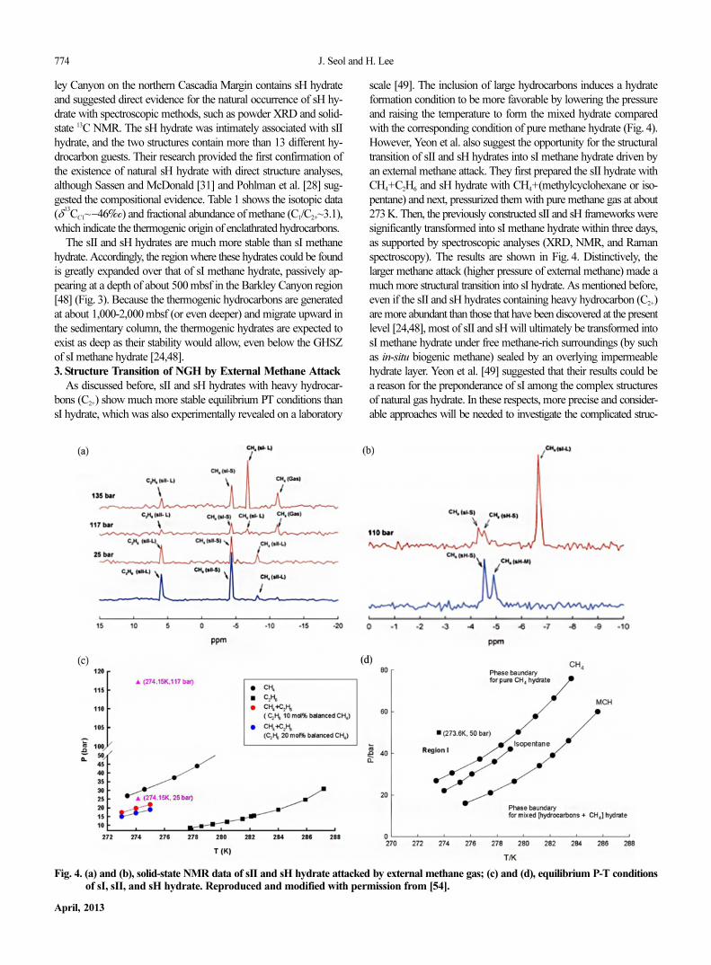
Fig. 3. The stability zones of methane hydrate and naturally occur-ring sII-sH complex gas hydrate from Barkley Canyon, off-shore Vancouver Island. Reproduced with permission from[48].
774 J. Seol and H. Lee
April, 2013
ley Canyon on the northern Cascadia Margin contains sH hydrateand suggested direct evidence for the natural occurrence of sH hy-drate with spectroscopic methods, such as powder XRD and solid-state 13C NMR. The sH hydrate was intimately associated with sIIhydrate, and the two structures contain more than 13 different hy-drocarbon guests. Their research provided the first confirmation ofthe existence of natural sH hydrate with direct structure analyses,although Sassen and McDonald [31] and Pohlman et al. [28] sug-gested the compositional evidence. Table 1 shows the isotopic data(δ
13
CC1~−46‰) and fractional abundance of methane (C1/C2+~3.1),which indicate the thermogenic origin of enclathrated hydrocarbons.
The sII and sH hydrates are much more stable than sI methanehydrate. Accordingly, the region where these hydrates could be foundis greatly expanded over that of sI methane hydrate, passively ap-pearing at a depth of about 500 mbsf in the Barkley Canyon region[48] (Fig. 3). Because the thermogenic hydrocarbons are generatedat about 1,000-2,000 mbsf (or even deeper) and migrate upward inthe sedimentary column, the thermogenic hydrates are expected toexist as deep as their stability would allow, even below the GHSZof sI methane hydrate [24,48].3. Structure Transition of NGH by External Methane Attack
As discussed before, sII and sH hydrates with heavy hydrocar-bons (C2+) show much more stable equilibrium PT conditions thansI hydrate, which was also experimentally revealed on a laboratory
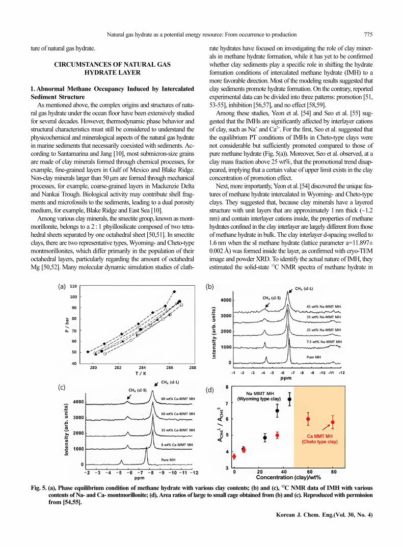
scale [49]. The inclusion of large hydrocarbons induces a hydrateformation condition to be more favorable by lowering the pressureand raising the temperature to form the mixed hydrate comparedwith the corresponding condition of pure methane hydrate (Fig. 4).However, Yeon et al. also suggest the opportunity for the structuraltransition of sII and sH hydrates into sI methane hydrate driven byan external methane attack. They first prepared the sII hydrate withCH4+C2H6 and sH hydrate with CH4+(methylcyclohexane or iso-pentane) and next, pressurized them with pure methane gas at about273 K. Then, the previously constructed sII and sH frameworks weresignificantly transformed into sI methane hydrate within three days,as supported by spectroscopic analyses (XRD, NMR, and Ramanspectroscopy). The results are shown in Fig. 4. Distinctively, thelarger methane attack (higher pressure of external methane) made amuch more structural transition into sI hydrate. As mentioned before,even if the sII and sH hydrates containing heavy hydrocarbon (C2+)are more abundant than those that have been discovered at the presentlevel [24,48], most of sII and sH will ultimately be transformed intosI methane hydrate under free methane-rich surroundings (by suchas in-situ biogenic methane) sealed by an overlying impermeablehydrate layer. Yeon et al. [49] suggested that their results could bea reason for the preponderance of sI among the complex structuresof natural gas hydrate. In these respects, more precise and consider-able approaches will be needed to investigate the complicated struc-
Fig. 4. (a) and (b), solid-state NMR data of sII and sH hydrate attacked by external methane gas; (c) and (d), equilibrium P-T conditionsof sI, sII, and sH hydrate. Reproduced and modified with permission from [54].
Natural gas hydrate as a potential energy resource: From occurrence to production 775
Korean J. Chem. Eng.(Vol. 30, No. 4)
ture of natural gas hydrate.
CIRCUMSTANCES OF NATURAL GAS
HYDRATE LAYER
1. Abnormal Methane Occupancy Induced by Intercalated
Sediment Structure
As mentioned above, the complex origins and structures of natu-ral gas hydrate under the ocean floor have been extensively studiedfor several decades. However, thermodynamic phase behavior andstructural characteristics must still be considered to understand thephysicochemical and mineralogical aspects of the natural gas hydratein marine sediments that necessarily coexisted with sediments. Ac-cording to Santamarina and Jang [10], most submicron-size grainsare made of clay minerals formed through chemical processes, forexample, fine-grained layers in Gulf of Mexico and Blake Ridge.Non-clay minerals larger than 50µm are formed through mechanicalprocesses, for example, coarse-grained layers in Mackenzie Deltaand Nankai Trough. Biological activity may contribute shell frag-ments and microfossils to the sediments, leading to a dual porositymedium, for example, Blake Ridge and East Sea [10].
Among various clay minerals, the smectite group, known as mont-morillonite, belongs to a 2 : 1 phyillosilicate composed of two tetra-hedral sheets separated by one octahedral sheet [50,51]. In smectiteclays, there are two representative types, Wyoming- and Cheto-typemontmorillonites, which differ primarily in the population of theiroctahedral layers, particularly regarding the amount of octahedralMg [50,52]. Many molecular dynamic simulation studies of clath-
rate hydrates have focused on investigating the role of clay miner-als in methane hydrate formation, while it has yet to be confirmedwhether clay sediments play a specific role in shifting the hydrateformation conditions of intercalated methane hydrate (IMH) to amore favorable direction. Most of the modeling results suggested thatclay sediments promote hydrate formation. On the contrary, reportedexperimental data can be divided into three patterns: promotion [51,53-55], inhibition [56,57], and no effect [58,59].
Among these studies, Yeon et al. [54] and Seo et al. [55] sug-gested that the IMHs are significantly affected by interlayer cationsof clay, such as Na+ and Ca2+. For the first, Seo et al. suggested thatthe equilibrium PT conditions of IMHs in Cheto-type clays werenot considerable but sufficiently promoted compared to those ofpure methane hydrate (Fig. 5(a)). Moreover, Seo et al. observed, at aclay mass fraction above 25 wt%, that the promotional trend disap-peared, implying that a certain value of upper limit exists in the clayconcentration of promotion effect.
Next, more importantly, Yeon et al. [54] discovered the unique fea-tures of methane hydrate intercalated in Wyoming- and Cheto-typeclays. They suggested that, because clay minerals have a layeredstructure with unit layers that are approximately 1 nm thick (~1.2nm) and contain interlayer cations inside, the properties of methanehydrates confined in the clay interlayer are largely different from thoseof methane hydrate in bulk. The clay interlayer d-spacing swelled to1.6 nm when the sI methane hydrate (lattice parameter a=11.897±0.002 Å) was formed inside the layer, as confirmed with cryo-TEMimage and powder XRD. To identify the actual nature of IMH, theyestimated the solid-state 13C NMR spectra of methane hydrate in
Fig. 5. (a), Phase equilibrium condition of methane hydrate with various clay contents; (b) and (c), 13C NMR data of IMH with variouscontents of Na- and Ca- montmorillonite; (d), Area ratios of large to small cage obtained from (b) and (c). Reproduced with permissionfrom [54,55].
776 J. Seol and H. Lee
April, 2013
Wyoming- and Cheto-type clays (Na- and Ca- montmorillonite, re-spectively). Basically, the chemical shifts of 13C NMR were revealedto about −6.7 ppm and −4.3 ppm for CH4 in sI-L and sI-S cages,respectively. As shown in Figs. 5(b) and (c), the methane occupancyratio of large to small cages in sI methane hydrate was significantlychanged according to the clay concentration. The 13C NMR peakarea ratio of large to small cages of bulk sI methane hydrate is knownto be about 3.7. However, the corresponding ratio in Na-montmo-rillonite increases with the clay concentration, up to 7.1 for 45 wt%Na-montmorillonite. In the other case, the ratio was increased upto 6 for 60 wt% Ca-montmorillonite. The overall results are sum-marized in Fig. 5(d). This result surprisingly suggested that signifi-cant portions (up to about 60%) of small cage in IMH were not oc-cupied by a methane guest. In other results of the 27Al, 29Si, and 23NaMAS NMR spectra from Yeon et al. [54], the 23Na peak of inter-layer Na+ cation in swollen Na-montmorillonite was far differentfrom that in the dry one, while the 27Al and 29Si peaks in the layeredcrystal structure of clay showed no change. Accordingly, Yeon etal. concluded that the interlayer cations of clay sediment, such asNa+ and Ca2+, may considerably affect the abnormal cage occu-pancy of IMH, and moreover, similar results were detected in thereal samples drilled from the East Sea, offshore Korea (see belowChapter 4.2).2. Abnormal Chlorinity Observed in Several Sites
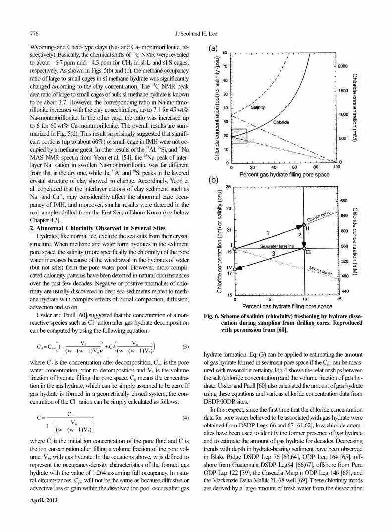
Hydrates, like normal ice, exclude the sea salts from their crystalstructure. When methane and water form hydrates in the sedimentpore space, the salinity (more specifically the chlorinity) of the porewater increases because of the withdrawal in the hydrates of water(but not salts) from the pore water pool. However, more compli-cated chlorinity patterns have been detected in natural circumstancesover the past few decades. Negative or positive anomalies of chlo-rinity are usually discovered in deep sea sediments related to meth-ane hydrate with complex effects of burial compaction, diffusion,advection and so on.
Ussler and Paull [60] suggested that the concentration of a non-reactive species such as Cl− anion after gas hydrate decompositioncan be computed by using the following equation:
(3)
where Cd is the concentration after decomposition, Cpw is the porewater concentration prior to decomposition and Vh is the volumefraction of hydrate filling the pore space. Ch means the concentra-tion in the gas hydrate, which can be simply assumed to be zero. Ifgas hydrate is formed in a geometrically closed system, the con-centration of the Cl− anion can be simply calculated as follows:
(4)
where Ci is the initial ion concentration of the pore fluid and C isthe ion concentration after filling a volume fraction of the pore vol-ume, Vh, with gas hydrate. In the equations above, w is defined torepresent the occupancy-density characteristics of the formed gashydrate with the value of 1.264 assuming full occupancy. In natu-ral circumstances, Cpw will not be the same as because diffusive oradvective loss or gain within the dissolved ion pool occurs after gas
hydrate formation. Eq. (3) can be applied to estimating the amountof gas hydrate formed in sediment pore space if the Cpw can be meas-ured with reasonable certainty. Fig. 6 shows the relationships betweenthe salt (chloride concentration) and the volume fraction of gas hy-drate. Ussler and Paull [60] also calculated the amount of gas hydrateusing these equations and various chloride concentration data fromDSDP/IODP sites.
In this respect, since the first time that the chloride concentrationdata for pore water believed to be associated with gas hydrate wereobtained from DSDP Legs 66 and 67 [61,62], low chloride anom-alies have been used to identify the former presence of gas hydrateand to estimate the amount of gas hydrate for decades. Decreasingtrends with depth in hydrate-bearing sediment have been observedin Blake Ridge DSDP Leg 76 [63,64], ODP Leg 164 [65], off-shore from Guatemala DSDP Leg84 [66,67], offshore from PeruODP Leg 122 [39], the Cascadia Margin ODP Leg 146 [68], andthe Mackenzie Delta Mallik 2L-38 well [69]. These chlorinity trendsare derived by a large amount of fresh water from the dissociation
Cd = Cpw 1−
Vh
w − w −1( )Vh( )-----------------------------------
⎝ ⎠⎛ ⎞
+ Ch
Vh
w − w −1( )Vh( )-----------------------------------⎝ ⎠⎛ ⎞
C =
Ci
1−
Vh
w − w −1( )Vh( )-----------------------------------
------------------------------------------------
Fig. 6. Scheme of salinity (chlorinity) freshening by hydrate disso-ciation during sampling from drilling cores. Reproducedwith permission from [60].
Natural gas hydrate as a potential energy resource: From occurrence to production 777
Korean J. Chem. Eng.(Vol. 30, No. 4)
of gas hydrate during core recovery. Accordingly, pore water fresh-ening is a useful signal for the presence of gas hydrate although otherprocesses can cause pore waters to decrease chlorinity. However,recently, pore waters with significantly enriched chlorinity coexistingwith the massive near seafloor hydrate were discovered in severalsites, representatively, in the Hydrate Ridge offshore Oregon, andUlleung Basin offshore Korea (for detailed phenomena, see belowChapters 4.1 and 4.2).
Over the past few years, several researchers have suggested numer-ical models to simulate gas hydrate formation in marine sedimentsassociated with salt exclusion [70,71]; however, they focused onthe negative chloride anomaly. Haeckel et al. presented an extraor-dinarily enriched chlorinity (up to 809 mM in pore water versus543 mM in seawater) from the sample drilled on the near seafloorat the southern summit of the Hydrate Ridge [72]. They quicklyseparated the solid hydrate from the surrounding sediment-pore watersystem and minimized the release of fresh water from hydrate dis-sociation to preserve the excluded chloride. They also suggested anumerical transport-reaction model to simulate the positive chlo-ride anomalies and calculated the hydrate formation rate (0.15-1.08mol•cm−2•yr−1, corresponding to 1.5×10³-1.08×10⁴ mol•m−2•yr−1).It is orders of magnitude larger than previously reported values (~10−3
mol•m−2•yr−1) for deep seated hydrate [70,71]. The estimated ratecan build up a hydrate layer with a thickness of 30-40 cm within 4-10 weeks. This formation rate cannot be achieved by the diffusionof dissolved methane alone; thus, near-seafloor methane hydrateshould be precipitated from methane gas bubbles: 0.2-1.3 gas bub-bles per cm3 of bulk sediment permanently present, as calculatedby the aforementioned researchers. Torres et al. [73] also developeda one-dimensional, non-steady state, transport-reaction model tosimulate the observed chloride enrichment at Site 1249 (see Chaper4.1 for details). Similar with the result from Haeckel et al. [72], theyshow that methane must be transported in the gas phase from thedepth of the BSR to the seafloor in order to reach the observed highchlorinity (up to 1,368mM). The kinetic constants of methane hydrateformation were dependent on depth below the seafloor and the for-mation rate was higher in shallow depth because the force of hydratecrystallization can overcome effective overburden stress.
According to the results of simulation, most of the methane hydrateobserved with highly chloride enriched pore water is likely to formfrom methane free gas rather than dissolved methane. Although theformation of gas hydrate from dissolved gas in natural porous mediawas revealed experimentally by Buffett and Zatsepina [74], dissolvedmethane seems to be not enough for reported positive Cl− anoma-lies. For a different point of view, several studies revealed that highlyenriched chlorinity could make methane free gas transport throughthe regional gas hydrate stability zone (RGHSZ) to the seafloor.
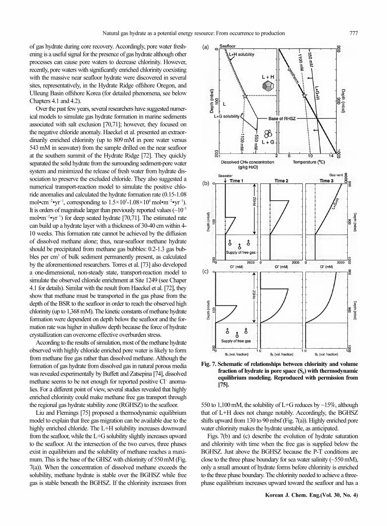
Liu and Flemings [75] proposed a thermodynamic equilibriummodel to explain that free gas migration can be available due to thehighly enriched chloride. The L+H solubility increases downwardfrom the seafloor, while the L+G solubility slightly increases upwardto the seafloor. At the intersection of the two curves, three phasesexist in equilibrium and the solubility of methane reaches a maxi-mum. This is the base of the GHSZ with chlorinity of 550 mM (Fig.7(a)). When the concentration of dissolved methane exceeds thesolubility, methane hydrate is stable over the BGHSZ while freegas is stable beneath the BGHSZ. If the chlorinity increases from
550 to 1,100 mM, the solubility of L+G reduces by ~15%, althoughthat of L+H does not change notably. Accordingly, the BGHSZshifts upward from 130 to 90 mbsf (Fig. 7(a)). Highly enriched porewater chlorinity makes the hydrate unstable, as anticipated.
Figs. 7(b) and (c) describe the evolution of hydrate saturationand chlorinity with time when the free gas is supplied below theBGHSZ. Just above the BGHSZ because the P-T conditions areclose to the three phase boundary for sea water salinity (~550 mM),only a small amount of hydrate forms before chlorinity is enrichedto the three phase boundary. The chlorinity needed to achieve a three-phase equilibrium increases upward toward the seafloor and has a
Fig. 7. Schematic of relationships between chlorinity and volumefraction of hydrate in pore space (Sh) with thermodynamicequilibrium modeling. Reproduced with permission from[75].
778 J. Seol and H. Lee
April, 2013
maximum value just below the seafloor; accordingly, more hydratecan be formed toward the seafloor. The chlorinity required for three-phase equilibrium is not achieved until hydrate saturation increasesto ~70% near the seafloor. Once the three-phase boundary reachesthe seafloor, it could be assumed to be a steady state (time 3). At thattime, no more hydrate accumulates because the amount of meth-ane supplied from below the BGHSZ becomes equal to that releasedat the seafloor. Eventually, a continuous methane migration channel,the so-called gas chimney, is constructed from near the BGHSZ tonear the seafloor. Liu and Fleming [75] noted that this is an equilib-rium model; thus, the gas hydrate saturation and chlorinity profilesare only determined by the inherent pressure and temperature pro-files of RGHSZ. In contrast, the gas supply rate determines howfast the three-phase boundary propagates through the RGHSZ withrespect to kinetics.
From another viewpoint, fractures, through which the free gasmigrates, nucleate when the excess pore pressure exceeds the verti-cal hydrostatic effective stress as hydrate saturation increases [76].Daigle and Dugan simulated salinity-sustained multiphase fluid flowat Hydrate Ridge (gas-dominated system) and Blake Ridge (water-dominated system). At Hydrate Ridge, free gas enters the RGHSZand migrates upward by fracturing the sediment as hydrate formsand salinity increases and eventually vents to the seafloor. How-ever, at Blake Ridge, free gas cannot enter the RGHSZ because waterflux removes excess salt before it reaches three phase equilibrium.Free gas can initiate fractures only at the BGHSZ and it makes thehighest Sh (hydrate volume fraction in pore space) at the BGHSZand relatively very low Sh throughout the RGHSZ.
In summary, the supply of free gas enriches chlorinity in porewater induced by massive methane hydrate formation, and enrichedchlorinity makes free gas migrate constituently through the RGHSZ.To accurately establish the chlorinity intimately related to the exist-ence of free gas and the amount of methane hydrate (Sh), an in-situ
chlorinity measurement is required to avoid hydrate dissociationduring sampling [77]. Recently, Seol et al. [78] designed a chlorinitymeasurement system under in-situ conditions of the deep sea floorpressure and temperature. They measured the chlorinity during meth-ane hydrate formation and controlled the formation rate with thecontact area between methane gas and sediment. The chlorinity in-creased under a fast formation rate; however, no noticeable changewas detected under a relatively low rate. The result showed that themethane hydrate formation rate should be maintained at least ~102
mol•cm−2•yr−1 to enrich chloride and maintain the elevated chlorinityin pore fluid. Although their experimental system did not perfectlyreflect all the external variables including hydrological, geometricaland physical circumstances of a deep-sea environment, they pro-vided insight into the development of abnormal positive chlorinityin natural system as the first experimental attempt.
CASE STUDY
1. Southern Summit of the Hydrate Ridge Offshore Oregon,
ODP Leg 204
The Hydrate Ridge is an accretionary ridge of the Cascadia sub-duction zone off of the Oregon coast, where the oceanic Juan deFuca plate is subducted beneath the continental North Americanplate. Hydrate Ridge has been the target of the Ocean Drilling Pro-
gram, Leg 146 and more recently Leg 204, thus underlying the im-portance of this area for gas hydrate research. Hydrate deposits andnumerous vents where gas bubbles and fluids are released into theseawater have been discovered at Hydrate Ridge [17,79].
Milkov et al. reported molecular and isotopic properties of hydrate-bound gases from 55 samples and void gases from 494 samplescollected during Ocean Drilling Program (ODP) Leg 204 [26]. Inan area of high gas flux at the southern summit of the ridge (Site1248-1250), shallow (0-40mbsf) gas hydrates are composed of main-ly allochthonous mixed microbial and thermogenic methane (>99%)and a small portion of thermogenic C2+ gases (up to about 0.4%),that migrated vertically and laterally from as deep as 2 to 2.5 kmdepths. Tréhu et al. [80] suggested that the seismic Horizon A hasa role as a migration conduit that supplies fluids into the GHSZ anda feed seepage at the southern summit of Hydrate Ridge. This hori-zon was drilled on Leg 204 and was found to represent a relativelypermeable layer of sand and ash with significant gas saturation [12].In contrast, deep (50-105 mbsf) gas hydrates at the southern sum-mit (Site 1248 and 1250) and on the flanks of the ridge (Site 1244-1247) are formed mainly from in-situ generated microbial methaneand ethane [26].
Kim et al. [81] revealed the structure of natural gas hydrate samplecollected at Site 1249 on ODP Leg 204 with XRD, solid-state 13CNMR, and Raman spectroscopy. The results indicate that the exam-ined sample was sI methane hydrate and cage occupancies werefound to be about 99% for large cages and 80% for small cages.Hester et al. [82] measured the near seafloor hydrates at HydrateRidge using a seagoing Raman spectrometer for the first time. Thenatural hydrates measured were sI structure with methane as thepredominant guest and cage occupancy ratios varied from 1.01 to1.30. It is possible for a small amount of sII hydrate to exist due toexistence of propane in some of the gas hydrate samples [26]. How-ever, sII hydrate was not found in the laboratory analysis and theseagoing Raman spectrometer [81,82].
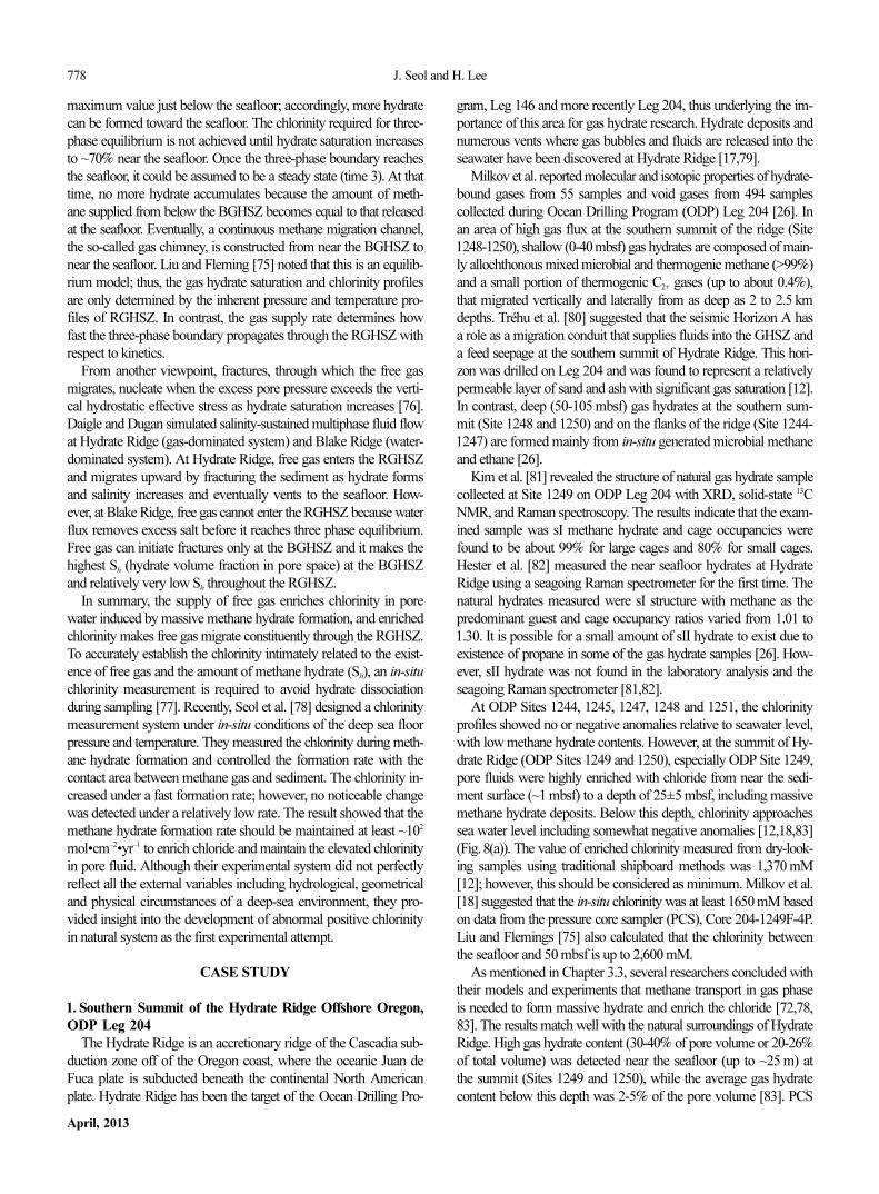
At ODP Sites 1244, 1245, 1247, 1248 and 1251, the chlorinityprofiles showed no or negative anomalies relative to seawater level,with low methane hydrate contents. However, at the summit of Hy-drate Ridge (ODP Sites 1249 and 1250), especially ODP Site 1249,pore fluids were highly enriched with chloride from near the sedi-ment surface (~1 mbsf) to a depth of 25±5 mbsf, including massivemethane hydrate deposits. Below this depth, chlorinity approachessea water level including somewhat negative anomalies [12,18,83](Fig. 8(a)). The value of enriched chlorinity measured from dry-look-ing samples using traditional shipboard methods was 1,370 mM[12]; however, this should be considered as minimum. Milkov et al.[18] suggested that the in-situ chlorinity was at least 1650 mM basedon data from the pressure core sampler (PCS), Core 204-1249F-4P.Liu and Flemings [75] also calculated that the chlorinity betweenthe seafloor and 50 mbsf is up to 2,600 mM.
As mentioned in Chapter 3.3, several researchers concluded withtheir models and experiments that methane transport in gas phaseis needed to form massive hydrate and enrich the chloride [72,78,83]. The results match well with the natural surroundings of HydrateRidge. High gas hydrate content (30-40% of pore volume or 20-26%of total volume) was detected near the seafloor (up to ~25 m) atthe summit (Sites 1249 and 1250), while the average gas hydratecontent below this depth was 2-5% of the pore volume [83]. PCS
Natural gas hydrate as a potential energy resource: From occurrence to production 779
Korean J. Chem. Eng.(Vol. 30, No. 4)
data from Site 1249 provides unique evidence of the natural co-existence of gas hydrate, hypersaline pore water, and free gas [18].Considering all information gathered from PCS data, sediment porespace consisted of 40% gas hydrate, 50% hypersaline pore water([Cl−]>1,800 mM), and 10% free gas. Hester et al. [82] also revealedthe existence of varying quantities of free methane gas with theirseagoing Raman analysis.
Actually, a methane vent at the southern summit of Hydrate Ridgewas discovered, and the amount of methane discharge from the seaf-loor was estimated to be ~104 mol•day−1 [84]. Tréhu et al. [83] esti-mated the amount of methane trapped in the hydrate deposits be-tween the seafloor and 30 mbsf to be 1.5-2×10⁸ m3 (correspondingto ~ 1010 mol) at STP. Assuming hydrate saturation and steady state,the methane supply rate is sufficient to form the total amount of
hydrate deposits currently present at the summit of Hydrate Ridgewithin a time scale of 500 years (Fig. 8(b)). Moreover, the hydrateformation rate near the seafloor is in the order of 102 mol•m−2•yr−1.Torres et al. [82] suggested that the massive hydrate observed withinshallow depth is driven primarily by a decrease of overburden stressin near surface sediments. The gas bubble and hydrate pressure willexceed the overburden effective stress and push away sediment parti-cles to form larger hydrate crystal. Torres et al. also proposed thatshallow massive hydrate deposits on Hydrate Ridge or elsewhererequire methane transport in gas phase at least to the depth wherebubble and hydrate pressure exceeds the effective overburden stress.
Integrating most available geological, geophysical, and geochemi-cal data, Milkov et al. [85] developed a reasonable model of gashydrate formation at the southern summit of Hydrate Ridge, as shown
Fig. 8. (a), Chloride data from ODP Leg Site 1249; (b), Schematic of mass transfer occurring in the southern summit of Hydrate Ridge.Reproduced with permission from [18,73].
Fig. 9. Scenario of the evolution of a brine patch observed at Hydrate Ridge. Reproduced with permission from [85].
780 J. Seol and H. Lee
April, 2013
in Fig. 9. When free gas migrated though the permeable Horizon Aand reached the intersection of Horizon A and BGHSZ, gas hydratestarted to precipitate (Fig. 9(a)). As free gas was vertically suppliedinto the RGHSZ, the hydrate propagated and eventually reachedthe seafloor (Fig.9(b)). The authigenic carbonate pinnacle [86] formedat the seafloor, which has very low permeability and acted as a sealfor gas migration (Fig. 9(c)) [87]. This was evidenced by the lackof gas bubbles coming from the pinnacle area [86,88]. The gas later-ally migrated to the crest of the anticline driven by buoyancy andprecipitated gas hydrate (Fig.9(d)). Pore water became highly enricheddue to extensive hydrate formation, and no more hydrate could pre-cipitate at the given temperature and pressure because of the enrichedchlorinity [18,75,76]. The free gas erupted to the seawater from theseafloor of Site 1249 [88]. However, the fundamental questions relatedto complicate mechanisms for gas transport and chlorinity enrich-ment remain unanswered.2. Ulleung Basin of the East Sea Offshore Korea
The Ulleung Basin is a deep, bowl-shaped, back-arc basin boundedby the steep continental slope of the eastern Korean Peninsula to thewest and the southern Korea Plateau to the north. Extensive geo-physical surveys have been conducted to find gas hydrate depositsin the Ulleung Basin since the late 1990s. The existence of gas hydratewas indicated by the presence of bottom simulating reflectors (BSRs)on multi-channel seismic profiles [89]. Generally, BSRs occur atthe interface between overlaying hydrate-bearing sediments withhigh velocity and underlying gas-bearing sediments with lower veloc-ity. This reflection coincides with the depth predicted from the phasediagram as the BGHSZ. Thus the BSRs are the most commonlyused geophysical indicators of marine gas hydrates and are oftenused to provide an initial indication of potential gas hydrate distri-bution. More recently, gas hydrate has been confirmed by pistoncoring, drilling expeditions [13,19,44,45,90,91] and laboratory spec-troscopic analysis [92].
During Ulleung Basin Gas Hydrate Expedition 1 (UBGH1), hy-drate-bearing sediments were recovered from three sites (UBGH1-4,UBGH1-9, and UBGH1-10). At one site, a 130-meter thick hydrate-bearing sediment of interbedded sands and clays was penetrated,which is one of the thickest hydrate-bearing intervals to be docu-mented worldwide [93]. Varying gas hydrate saturation with depthand a wide variety of lithologies were revealed from the drilled coreat UBGH1-9 [90]. Negative chloride anomalies compared to thein-situ background chloride level were also observed between 63-151 mbsf. Hydrate saturations were estimated from the chlorinityanomalies up to 63.5% of pore volume with an average of 9.9%.Bahk et al. [19] concluded that the gas hydrate occurs in two dif-
ferent types in this zone. In Facies Association I (FA I) (0-98 mbsf)consisting mainly of alternating thin to medium bedded hemipe-lagic mud and turbidite sand or mud beds, the pore-filling type ispreferentially associated with turbidite sand beds filling the porespace. The fracture-filling type formed as vein or nodule types oc-curs with filling fractures and faults of FA III (126-178 mbsf) com-posed of mostly diatomaceous hemipelagic mud without discreteturbidite sand layers. However, abnormally low gas hydrate satura-tions were detected in the interval FA II (98-126 mbsf) despite thedominance of turbidite sand or sandy debris flow bed which couldhave enhanced hydrate formation with low capillary force.
Compositional and structural analyses of gas hydrate samplesrevealed that they consist of sI hydrates containing more than 99%of biogenic methane. As discussed in Chapter 2.1 and shown in Fig.2, the estimated δ
13
C values of methane are between −60 and −80‰and C1/C2+ ratios are over or around 1000, which suggests that hy-drocarbons discovered in the Ulleung Basin are preferentially gen-erated by microbial reduction of CO2 [19,44,45]. Bahk et al. [19]confirmed all the crystal structure of hydrate samples collected fromfive piston cores (P06, P08, P11, P12, and P18 from UBGH1) tobe Pm3n structure I using powder XRD measurement. Based onthe NMR and FT-Raman spectroscopic analysis, they suggestedthat the cage occupancies were about 0.99 for large cages and 0.65-0.85 for small cages (Table 2).
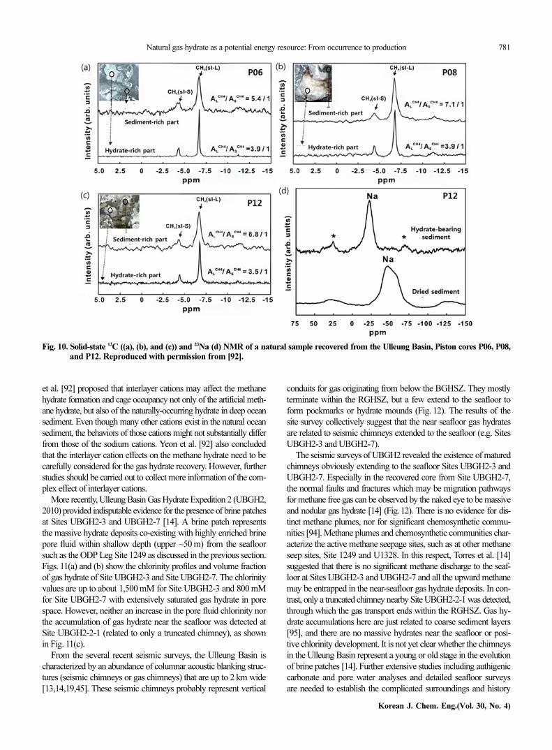
Yeon et al. [92] evaluated the cage occupancy ratio of three gashydrate samples from P06, P08, and P12 with solid-state 13C NMR(Fig. 10 and Table 2). They focused on the hydrate in the sediment-rich part of the natural sample based on their previous result fromartificial intercalated methane hydrate (IMH) with clay minerals[54]. The two peaks of methane in sI-S (−4.3 ppm) and sI-L (−6.7ppm) were the same for all the hydrates in both the white-lookinghydrate-rich part and grey-looking sediment-rich part. For the hydrate-rich part, the area ratio of large to small cages ranged from 3.5 to3.9 (corresponding to a cage occupancy ratio, θL/θS of 1.17 to 1.3),which is quite close to the ideal ratio of 3.75. In contrast, for thesediment rich part, the AL/AS ratio ranged from 5.4 to 7.1 (corre-sponding to θL/θS of 1.8 to 2.37), similar with that of the artificialIMH in their previous study. Yeon et al. [92] also compared the 23Nachemical shift of sediment-rich hydrate with that of dried sediment.Peaks appeared at about −50 ppm for dry sediment and −25 ppmfor hydrate-bearing sediment, and all the samples from P06, P08and P12 showed the same pattern (Fig. 10(d)). Simultaneously, therewas no change of chemical shift in 27Al and 29Si, which are covalentlylinked to oxygen and hydrogen atoms for the layered clay struc-ture, between dried sediment and hydrate-bearing sediment. Yeon
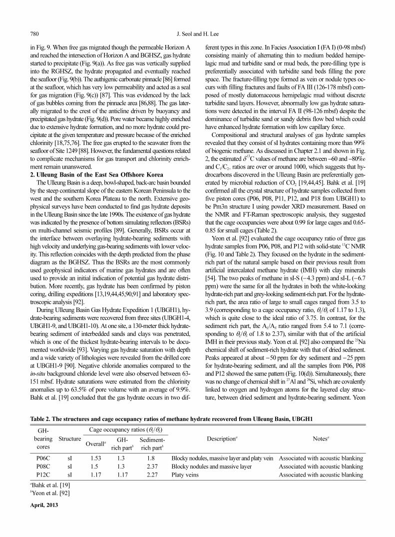
Table 2. The structures and cage occupancy ratios of methane hydrate recovered from Ulleung Basin, UBGH1
GH-
bearing
cores
Structure
Cage occupancy ratios (θL/θS)
Descriptiona Notesa
OverallaGH-
rich partbSediment-
rich partb
P06C sI 1.53 1.30 1.80 Blocky nodules, massive layer and platy vein Associated with acoustic blanking
P08C sI 1.50 1.30 2.37 Blocky nodules and massive layer Associated with acoustic blanking
P12C sI 1.17 1.17 2.27 Platy veins Associated with acoustic blanking
aBahk et al. [19]bYeon et al. [92]
Natural gas hydrate as a potential energy resource: From occurrence to production 781
Korean J. Chem. Eng.(Vol. 30, No. 4)
et al. [92] proposed that interlayer cations may affect the methanehydrate formation and cage occupancy not only of the artificial meth-ane hydrate, but also of the naturally-occurring hydrate in deep oceansediment. Even though many other cations exist in the natural oceansediment, the behaviors of those cations might not substantially differfrom those of the sodium cations. Yeon et al. [92] also concludedthat the interlayer cation effects on the methane hydrate need to becarefully considered for the gas hydrate recovery. However, furtherstudies should be carried out to collect more information of the com-plex effect of interlayer cations.
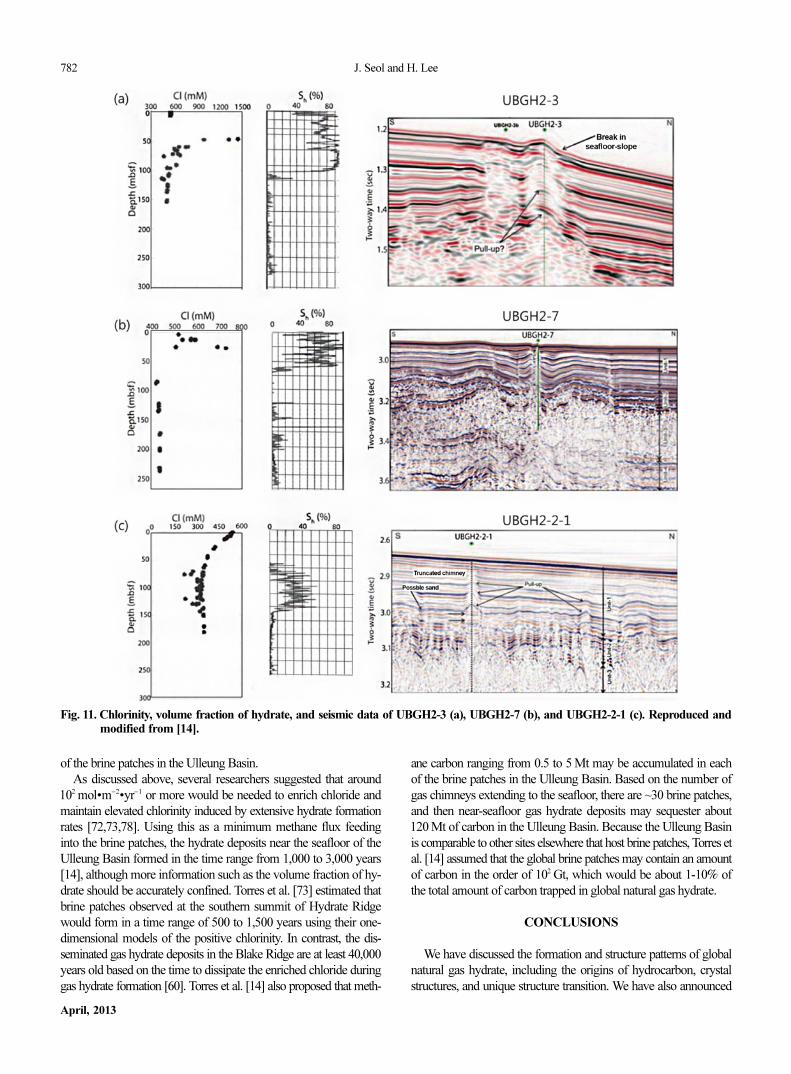
More recently, Ulleung Basin Gas Hydrate Expedition 2 (UBGH2,2010) provided indisputable evidence for the presence of brine patchesat Sites UBGH2-3 and UBGH2-7 [14]. A brine patch representsthe massive hydrate deposits co-existing with highly enriched brinepore fluid within shallow depth (upper ~50 m) from the seafloorsuch as the ODP Leg Site 1249 as discussed in the previous section.Figs. 11(a) and (b) show the chlorinity profiles and volume fractionof gas hydrate of Site UBGH2-3 and Site UBGH2-7. The chlorinityvalues are up to about 1,500 mM for Site UBGH2-3 and 800 mMfor Site UBGH2-7 with extensively saturated gas hydrate in porespace. However, neither an increase in the pore fluid chlorinity northe accumulation of gas hydrate near the seafloor was detected atSite UBGH2-2-1 (related to only a truncated chimney), as shownin Fig. 11(c).
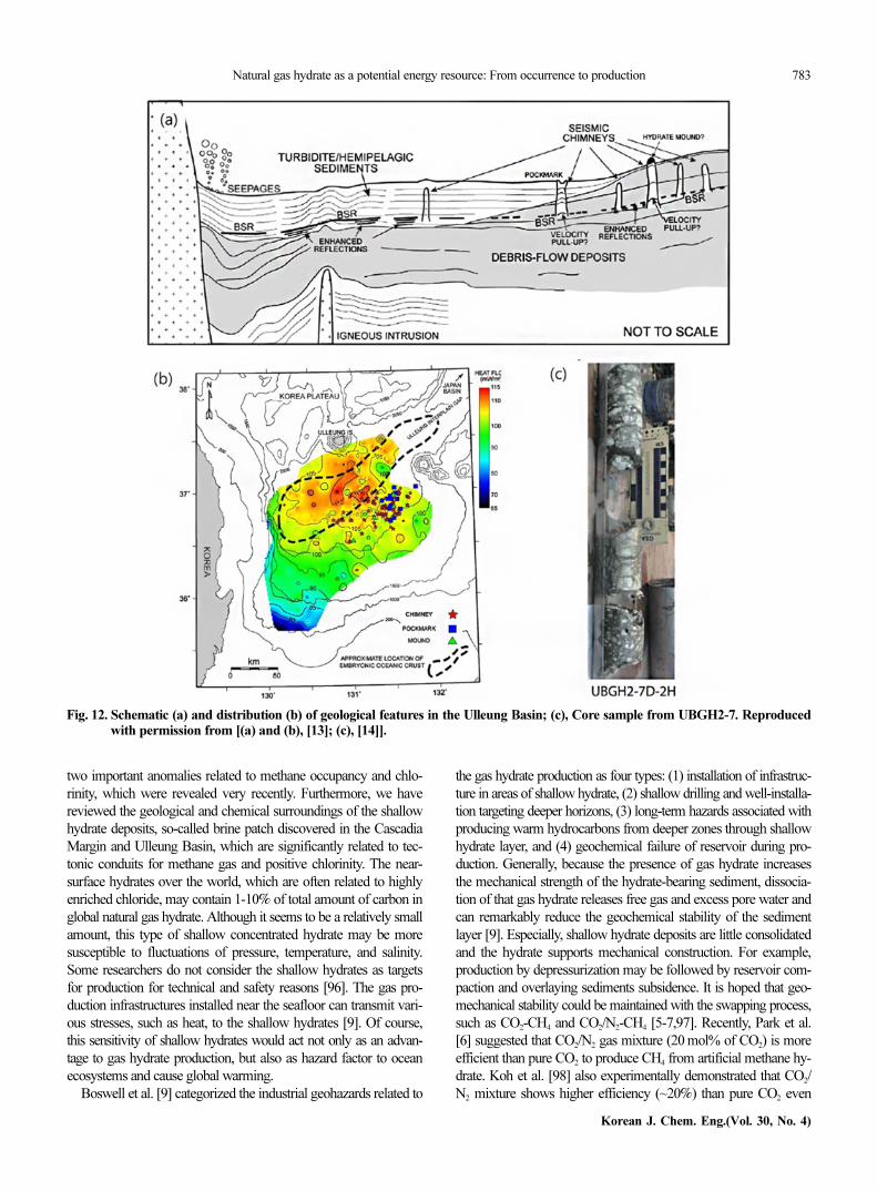
From the several recent seismic surveys, the Ulleung Basin ischaracterized by an abundance of columnar acoustic blanking struc-tures (seismic chimneys or gas chimneys) that are up to 2 km wide[13,14,19,45]. These seismic chimneys probably represent vertical
conduits for gas originating from below the BGHSZ. They mostlyterminate within the RGHSZ, but a few extend to the seafloor toform pockmarks or hydrate mounds (Fig. 12). The results of thesite survey collectively suggest that the near seafloor gas hydratesare related to seismic chimneys extended to the seafloor (e.g. SitesUBGH2-3 and UBGH2-7).
The seismic surveys of UBGH2 revealed the existence of maturedchimneys obviously extending to the seafloor Sites UBGH2-3 andUBGH2-7. Especially in the recovered core from Site UBGH2-7,the normal faults and fractures which may be migration pathwaysfor methane free gas can be observed by the naked eye to be massiveand nodular gas hydrate [14] (Fig.12). There is no evidence for dis-tinct methane plumes, nor for significant chemosynthetic commu-nities [94]. Methane plumes and chemosynthetic communities char-acterize the active methane seepage sites, such as at other methaneseep sites, Site 1249 and U1328. In this respect, Torres et al. [14]suggested that there is no significant methane discharge to the seaf-loor at Sites UBGH2-3 and UBGH2-7 and all the upward methanemay be entrapped in the near-seafloor gas hydrate deposits. In con-trast, only a truncated chimney nearby Site UBGH2-2-1 was detected,through which the gas transport ends within the RGHSZ. Gas hy-drate accumulations here are just related to coarse sediment layers[95], and there are no massive hydrates near the seafloor or posi-tive chlorinity development. It is not yet clear whether the chimneysin the Ulleung Basin represent a young or old stage in the evolutionof brine patches [14]. Further extensive studies including authigeniccarbonate and pore water analyses and detailed seafloor surveysare needed to establish the complicated surroundings and history
Fig. 10. Solid-state 13C ((a), (b), and (c)) and 23Na (d) NMR of a natural sample recovered from the Ulleung Basin, Piston cores P06, P08,and P12. Reproduced with permission from [92].
782 J. Seol and H. Lee
April, 2013
of the brine patches in the Ulleung Basin.As discussed above, several researchers suggested that around
102 mol•m−2•yr−1 or more would be needed to enrich chloride andmaintain elevated chlorinity induced by extensive hydrate formationrates [72,73,78]. Using this as a minimum methane flux feedinginto the brine patches, the hydrate deposits near the seafloor of theUlleung Basin formed in the time range from 1,000 to 3,000 years[14], although more information such as the volume fraction of hy-drate should be accurately confined. Torres et al. [73] estimated thatbrine patches observed at the southern summit of Hydrate Ridgewould form in a time range of 500 to 1,500 years using their one-dimensional models of the positive chlorinity. In contrast, the dis-seminated gas hydrate deposits in the Blake Ridge are at least 40,000years old based on the time to dissipate the enriched chloride duringgas hydrate formation [60]. Torres et al. [14] also proposed that meth-
ane carbon ranging from 0.5 to 5 Mt may be accumulated in eachof the brine patches in the Ulleung Basin. Based on the number ofgas chimneys extending to the seafloor, there are ~30 brine patches,and then near-seafloor gas hydrate deposits may sequester about120 Mt of carbon in the Ulleung Basin. Because the Ulleung Basinis comparable to other sites elsewhere that host brine patches, Torres etal. [14] assumed that the global brine patches may contain an amountof carbon in the order of 102 Gt, which would be about 1-10% ofthe total amount of carbon trapped in global natural gas hydrate.
CONCLUSIONS
We have discussed the formation and structure patterns of globalnatural gas hydrate, including the origins of hydrocarbon, crystalstructures, and unique structure transition. We have also announced
Fig. 11. Chlorinity, volume fraction of hydrate, and seismic data of UBGH2-3 (a), UBGH2-7 (b), and UBGH2-2-1 (c). Reproduced andmodified from [14].
Natural gas hydrate as a potential energy resource: From occurrence to production 783
Korean J. Chem. Eng.(Vol. 30, No. 4)
two important anomalies related to methane occupancy and chlo-rinity, which were revealed very recently. Furthermore, we havereviewed the geological and chemical surroundings of the shallowhydrate deposits, so-called brine patch discovered in the CascadiaMargin and Ulleung Basin, which are significantly related to tec-tonic conduits for methane gas and positive chlorinity. The near-surface hydrates over the world, which are often related to highlyenriched chloride, may contain 1-10% of total amount of carbon inglobal natural gas hydrate. Although it seems to be a relatively smallamount, this type of shallow concentrated hydrate may be moresusceptible to fluctuations of pressure, temperature, and salinity.Some researchers do not consider the shallow hydrates as targetsfor production for technical and safety reasons [96]. The gas pro-duction infrastructures installed near the seafloor can transmit vari-ous stresses, such as heat, to the shallow hydrates [9]. Of course,this sensitivity of shallow hydrates would act not only as an advan-tage to gas hydrate production, but also as hazard factor to oceanecosystems and cause global warming.
Boswell et al. [9] categorized the industrial geohazards related to
the gas hydrate production as four types: (1) installation of infrastruc-ture in areas of shallow hydrate, (2) shallow drilling and well-installa-tion targeting deeper horizons, (3) long-term hazards associated withproducing warm hydrocarbons from deeper zones through shallowhydrate layer, and (4) geochemical failure of reservoir during pro-duction. Generally, because the presence of gas hydrate increasesthe mechanical strength of the hydrate-bearing sediment, dissocia-tion of that gas hydrate releases free gas and excess pore water andcan remarkably reduce the geochemical stability of the sedimentlayer [9]. Especially, shallow hydrate deposits are little consolidatedand the hydrate supports mechanical construction. For example,production by depressurization may be followed by reservoir com-paction and overlaying sediments subsidence. It is hoped that geo-mechanical stability could be maintained with the swapping process,such as CO2-CH4 and CO2/N2-CH4 [5-7,97]. Recently, Park et al.[6] suggested that CO2/N2 gas mixture (20 mol% of CO2) is moreefficient than pure CO2 to produce CH4 from artificial methane hy-drate. Koh et al. [98] also experimentally demonstrated that CO2/N2 mixture shows higher efficiency (~20%) than pure CO2 even
Fig. 12. Schematic (a) and distribution (b) of geological features in the Ulleung Basin; (c), Core sample from UBGH2-7. Reproducedwith permission from [(a) and (b), [13]; (c), [14]].
784 J. Seol and H. Lee
April, 2013
for a NGH sample recovered from the East Sea. The methods ofoil and gas production from a conventional reservoir can also causethe thermal destabilization of shallow hydrate due to heated well-bores [99,100]. The most important consideration is that sufficientunderstanding and accurate analyses of the complex surroundingsin natural system must occur before we can apply the methane re-covery process to real systems to optimize the process and pre-serve the ocean environment.
ACKNOWLEDGEMENT
This work was supported by the National Research Foundationof Korea government (MEST) (No. 2010-0029176, WCU program:31-2008-000-10055-0). This research was also supported by theMinistry of Knowledge Economy through the Recovery/Produc-tion of Natural Gas Hydrate using Swapping Technique (KIGAM -Gas Hydrate R&D Organization).
REFERENCES
1. K. A. Kvenvolden and T. D. Lorenson, in Natural gas hydrates; oc-
currence, distribution, and detection, C. K. Paull and W. P. Dillon
Eds., American Geophysical Union, Washington DC, Geophysical
Monograph, 124, 3-18 (2001).
2. K. A. Kvenvolden, Proc. Natl. Acad. Sci. USA, 96, 3420 (1999).
3. J. Seol, J.-W. Lee, D.-Y. Kim, S. Takeya, J. A. Ripmeester and H.
Lee, J. Phys. Chem. B, 114, 804 (2010a).
4. J. Seol, J.-W. Lee, W. Shin, D.-Y. Koh, J. Lee and H. Lee, J. Phys.
Chem. C, 114, 17960 (2010b).
5. H. Lee, Y. Seo, Y.-T. Seo, I. L. Moudrakovski and J. A. Ripmeester,
Angew. Chem. Int. Ed., 115, 5202 (2003).
6. Y. Park, D.-Y. Kim, J.-W. Lee, D.-G. Huh, K.-P. Park, J. Lee and H.
Lee, Proc. Natl. Acad. Sci. USA, 103, 12690 (2006).
7. K. Shin, Y. Park, M. Cha, K.-P. Park, D.-G. Huh, J. Lee, S.-J. Kim
and H. Lee, Energy & Fuels, 22, 3160 (2008).
8. R. Boswell and T. Collett, FITI, 6(3), 5 (2006).
9. R. Boswell, T. Collett, S. Dallimore and M. Frye, FITI, 12(1), 11
(2012).
10. J. C. Santamarina and J. Jang, FITI, 9(4), 18 (2009).
11. A. H. Johnson, FITI, 11(2), 1 (2011).
12. A. M. Tréhu, G. Bohrmann, F. R. Rack and M. E. Torres, Proceed-
ings of ODP, Initial Reports 204, [online] http://www-odp.tamu.edu/
publications/e04_IR/204ir.htm (2003).
13. S. Horozal, G. H. Lee, B. Y. Yi, D. G. Yoo, K. P. Park, H. Y. Lee, W.
Kim, H. J. Kim and K. Lee, Mar. Geol., 258, 126 (2009).
14. M. E. Torres, J. H. Kim, J.-Y. Choi, B.-J. Ryu, J.-J. Bahk, M. Riedel,
T. S. Collett, W.-L. Hong and M. Kastner, Proceedings of the 7th
international conference on gas hydrates, Edinburgh, Scotland,
United Kingdom (2011).
15. R. Sassen, S. T. Sweet, A. V. Milkov, D. A. DeFreitas and M. C.
Kennicutt, in Natural gas hydrates; occurrence, distribution, and
detection, C. K. Paull and W. P. Dillon Eds., American Geophysical
Union, Washington DC, Geophysical Monograph, 124, 131 (2001).
16. J. Ashi, S. Saito, K. Aoike, T. Toki, T. Kuramoto and P. Henry, EOS
Transaction, American Geophysical Union, 83, Fall meeting sup-
plement (Abstract), T11B-1248 (2002).
17. E. Suess, M. E. Torres, G. Bohrmann, R. W. Collier, D. Rickert, C.
Goldfinger, P. Linke, A. Heuser, H. Sahling, K. Heeschen, C. Jung, K.
Nakamura, J. Greinert, O. Pfannkuche, A. M. Tréhu, G. Klinkhamer,
M. J. Whiticar, A. Eisenhauer, B. Teichert and M. Elvert, in Natural
gas hydrates; occurrence, distribution, and detection, C. K. Paull
and W. P. Dillon Eds., American Geophysical Union, Washington
DC, Geophysical Monograph, 124, 87 (2001).
18. A. V. Milkov, G. R. Dickens, G. E. Claypool, Y.-J. Lee, W. S. Boron-
wski, M. E. Torres, W. Xu, H. Tomaru, A. M. Tréhu and P. Schulth-
eiss, Earth Planet. Sci. Lett., 222, 829 (2004).
19. J. J. Bahk, J.-H. Kim, G.-S. Kong, Y. Park, H. Lee, Y. Park and K. P.
Park, Geosci. J., 13, 371 (2009).
20. C. K. Paull, W. Ussler and W. S. Borowski, in International confer-
ence on natural gas hydrates, E. D. Sloan, J. Happel and M. A.
Hnaow Eds., Annals of the New York Academy of Sciences, 715,
392 (1994).
21. M. J. Whiticar, E. F. Faber and M. Schoell, Geochim. Cosmochim.
Acta, 50, 693 (1986).
22. M. J. Whiticar, Chem. Geol., 161, 291 (1999).
23. M. Schoell, Chem. Geol., 71, 1 (1988).
24. J. M. Brooks, M. C. Kennicutt, R. R. Fey, T. J. McDonald and R.
Sassen, Science, 225, 409 (1984).
25. G. D. Ginsburg, in Gas hydrates: Relevance to world margin stabil-
ity and climatic change, J.-P. Henriet and J. Mienert, Eds., Geologi-
cal Society, London, Special Publication, 137, 51 (1998).
26. A. V. Milkov, G. E. Claypool, Y. J. Lee and R. Sassen, Geochim. Cos-
mochim. Acta, 69, 1007 (2005).
27. N. R. Champman, J. W. Pohlman, R. B. Coffin, J. P. Chanton and
L. Lapham, EOS Trans., 85, 361 (2004).
28. J. W. Pohlman, E. A. Canuel, N. R. Chapman, G. D. Spence, M. J.
Whiticar and R. B. Coffin, Org. Geochem., 36, 703 (2005).
29. R. Matsumoto, H. Tomaru, A. Hiruta, Y. Ishida, R. Takeuchi, G. Sny-
der, R. Kotani, Y. Okuda, M. Sato, H. Numanami, C. Aoyama, M.
Hiromatsu, H. Lu, N. S. Matsuda, Z. Lu, E. Takeuchi, T. Goto, H.
Machiyama, H. Toh and J. Komatsubara, American geophysical
union fall meeting, Abstract no.OS41C-04 (2005).
30. R. Sassen, S. T. Sweet, A. V. Milkov, D. A. DeFreitas and M. C.
Kennicutt, Geology, 29, 107 (2001).
31. R. Sassen and I. R. Mcdonald, Org. Geochem., 22, 1029 (1994).
32. R. Sassen, S. Joye, S. E. Sweet, D. A. DeFreias, A. V. Milkov and
I. R. McDonald, Org. Geochem., 30, 485 (1999).
33. J. M. Brooks, B. H. Cox, W. R. Bryant, M. C. Kennicutt, R. G. Mann
and T. J. McDonald, Org. Geochem., 10, 221 (1986).
34. J. M. Brooks, M. E. Field and M. C. Kennicutt, Marine Geol., 96,
103 (1991).
35. G. Ginsburg, A. N. Kremlev, M. N. Grigor’ev, G. V. Larkin, A. D.
Pavlenkin and N. A. Saltykova, Geologiyai Geofizika, 313, 10
(1990).
36. V. N. Blinova, M. K. Ivanov and G. Bohrmann, Geo-Mar. Lett., 23,
250 (2003).
37. G. D. Ginsburg, R. A. Guseynov, A. A. Dadashev, G. A. Ivanova,
S. A. Kazantsev, V. A. Soloviev, E. V. Telepnev, P. Ye. Askefi-Nasi-
nov, A. A. Yesikov, V. I. Mal’tseva, G. Yu. Mashirov and I. Yu. Sha-
bayeva, Int. Geol. Rev., 43, 765 (1992).
38. G. Ginsburg, V.A. Soloviev, R.E. Cranston, T.D. Lorenson and K.A.
Kvenvolden, Geo-Mar. Lett., 13, 41 (1993).
39. K. A. Kvenvolden and M. Kastner, in Proceedings of ocean drill-
ing program, scientific results, 112, E. Suess and R. von Huene, et
Natural gas hydrate as a potential energy resource: From occurrence to production 785
Korean J. Chem. Eng.(Vol. 30, No. 4)
al. Eds., College station, TX, 517-526 (1990).
40. T. S. Collett, Am. Assoc. Petrol. Geol. Bull., 77, 793 (1993).
41. T. D. Lorenson, M. J. Whiticar, A. Waseda, S. R. Dallimore and T. S.
Collett, in Scientific Results from JAPEX.JNOC/GSC Mallik 2L-38
Gas Hydrate Research Well, Mackenzie Delta, Northwest Territo-
ries, Canada, S. R. Dallimore, T. Uchida and T. S. Collett Eds., Geo-
logical Survey of Canada Bulletin, 544, 143 (1999).
42. T. D. Lorenson and T. S. Collett, in Proceedings of ocean drilling
program, C. K. Paull, R. Matsumoto, P. J. Wallace and W. P. Dillon
Eds., College Station, TX, 37-46 (2000).
43. A. Waseda and T. Uchida, Proceedings of 4th International Confer-
ence on Gas Hydrates, Yokohama, Japan, 19-174 (2002).
44. J. H. Kim, M.-H. Park and J.-H. Chun, Geo-Mar. Lett., 31, 37 (2011).
45. J. H. Kim, M. E. Torres, J. Choi, J.-J. Bahk, M.-H. Park and W. L.
Hong, Org. Geochem., 43, 26 (2012).
46. D. W. Davidson, S. K. Garg, S. R. Gough, Y. P. Handa, C. I. Ratc-
liffe, J. A. Ripmeester, J. S. Tse and W. F. Lawson, Geochim. Cos-
mochim. Acta, 50, 619 (1986).
47. J. A. Ripmeester, J. S. Tse, C. I. Ratcliffe and B. N. Powell, Nature,
325, 135 (1987).
48. H. Lu, Y. Seo, J. Lee, I. Moudrakovski, J. A. Ripmeester, N. R. Chap-
man, R. B. Coffin, G. Gardner and J. Pohlman, Nature, 445, 303
(2007).
49. S.-H. Yeon, J. Seol and H. Lee, J. Am. Chem. Soc., 128, 12388
(2006).
50. R. E. Grim, Clay Mineralogy, 2nd Ed., McGraw-Hill (1968).
51. H. Ouar, S. B. Cha, T. R. Wildeman and E. D. Sloan, Chem. Eng.
Res. Des., 70, 48 (1992).
52. R. E. Grim and G. Kulbicki, Am. Mineral., 46, 1329 (1961).
53. S. B. Cha, H. Ouar, T. R. Wildeman and E. D. Sloan, J. Phys. Chem.,
92, 6492 (1988).
54. S.-H. Yeon, J. Seol, Y. Seo, Y. Park, D.-Y. Koh, K.-P. Park, D.-G.
Huh, J. Lee and H. Lee, J. Phys. Chem. B Lett., 113, 245 (2009).
55. Y. Seo, J. Seol, S.-H. Yeon, D.-Y. Koh, M. Cha, S.-P. Kang, Y.-T.
Seo, J. Bahk, J. Lee and H. Lee, J. Chem. Eng. Data, 54, 1284 (2009).
56. E. M. Chuvilin, E. V. Kozlova, N. A. Makhonina, V. S. Yakushew
and D. V. Dubinyak, Proceedings of 4th International Conference
on Gas Hydrates, 433-438 (2002).
57. S. Guggenheim and A.F. Koster van Groos, Geology, 31, 653 (2003).
58. P. Englezos and S. Hall, Can. J. Chem. Eng., 72, 887 (1994).
59. K. M. Lee, H. Lee, J.-H. Lee and J. M. Kang, Geophy. Res. Lett.,
29, 2034 (2002).
60. W. Ussler and C. K. Paull, in Natural gas hydrates; occurrence, dis-
tribution, and detection, C. K. Paull and W. P. Dillon Eds., Ameri-
can Geophysical Union, Washington DC, Geophysical Monograph,
124, 41 (2001).
61. W. E. Harrison, R. Hesse and J. M. Gieskes, in Initial reports of the
deep sea drilling project, J. Aubouin, et al., Eds., U. S. Government
Printing Office, Washington, D.C. (1982).
62. J. M. Gieskes, K. Johnston and M. Boehm, in Initial reports of the
deep sea drilling project, R. von Huene, et al. Eds., U.S. Govern-
ment Printing Office, Washington, D.C. (1985).
63. K.A. Kvenvolden and L.A. Barnard, Initial Reports, Deep Sea Drill-
ing Project, 76, 353 (1983).
64. P. D. Jenden and J. M. Gieskes, Initial Reports Deep Sea Drilling
Project, 76, 453 (1983).
65. C. K. Paull, T. D. Lorenson, W. S. Boroworski, W. Ussler, K. Olsen,
N. M. Rodriguez and H. Wehner, Proceedings of Ocean Drilling
Program Scientific Results, 164, 67 (2000).
66. K. A. Kvenvolden and T. J. Mcdonald, Initial Reports, Deep Sea
Drilling Project, 84, 667 (1985).
67. R. Hesse, J. Lebel and J. M. Gieskes, Initial Reports, Deep Sea Drill-
ing Project, 84, 727 (1985).
68. M. J. Whiticar, M. Hovland, M. Kastner and J. C. Sample, Proc.
Ocean Drill. Program, Sci. Results, 146, 385 (1995).
69. R. E. Cranston, in Scientific Results from JAPEX.JNOC/GSC Mal-
lik 2L-38 Gas Hydrate Research Well, Mackenzie Delta, Northwest
Territories, Canada, S. R. Dallimore, T. Uchida and T. S. Collett
Eds., Geological Survey of Canada Bulletin, 544, 295 (1999).
70. P. K. Egeberg and G. R. Dickens, Chem. Geol., 153, 53 (1999).
71. M. K. Davie and B. A. Buffet, J. Geophys. Res., 106, 497 (2001).
72. M. Haeckel, E. Suess, K. Wallman and E. Rickert, Geochim. Cos-
mochim. Acta, 68, 4335 (2004).
73. M. E. Torres, K. Wallmann, A. M. Tréhu, G. Bohrmann, W. S.
Borowski and H. Tomaru, Earth Planet. Sci. Lett., 226, 225 (2004).
74. B. A. Buffett and O. Y. Zatsepina, Marine Geol., 164, 69 (1999).
75. X. Liu and P. B. Flemings, Earth Planet. Sci. Lett., 241, 211 (2006).
76. H. Daigle and B. Dugan, Geophys. Res. Lett., 37, L20301 (2010).
77. R. Hesse, Earth Sci. Rev., 61, 149 (2003).
78. J. Seol, D.-Y. Koh, M. Cha, W. Shin, Y.-J. Lee, J.-H. Kim, J. Lee and
H. Lee, AIChE J. 58, 322 (2012).
79. E. Suess, M. E. Torres, G. Bohrmann, R. W. Collier, J. Greinert, P.
Linke, G. Rehder, A. M. Tréhu, K. Wallmann, G. Winckler and E.
Zuleger, Earth Planet. Sci. Lett., 170, 1 (1999).
80. A. M. Tréhu, N. L. Bangs, M. A. Arsenault, G. Bohrmann, C. Gold-
finger, J. E. Johnson, Y. Nakamura and M. E. Torres, Proceedings
of the 4th International Gas Hydrate, Yokohama, Japan, 90-96 (2002).
81. D.-Y. Kim, T.-W. Uhm, H. Lee, Y.-J. Lee, B.-J. Ryu and J.-H. Kim,
Korean J. Chem. Eng., 22, 569 (2005).
82. K. C. Hester, R. M. Dunk, S. N. White, P. G. Brewer, E. T. Peltzer
and E. D. Sloan, Geochim. Cosmochim. Acta, 71, 2947 (2007).
83. A. M. Tréhu, P. E. Long, M. E. Torres, G. Bohrmann, F. R. Rack,
T. S. Collett, D. S. Goldberg, A. V. Milkov, M. Ridel, P. Schulth-
eiss, N. L. Bangs, S. R. Barr, W. S. Borowski, G. E. Claypool, M. E.
Delwiche, G. R. Dickens, E. Gracia, G. Guerin, M. Holland, J. E.
Johnson, Y.-J. Lee, C.-S. Liu, X. Su, B. Teichert, H. Tomaru, M. Van-
neste, M. Watanabe and J. L. Weinberger, Earth Planet. Sci. Lett.,
222, 845 (2004).
84. K. U. Heeschen, R. W. Collier, M. A. de Angelis, E. Suess, G. Reh-
der, P. Linke and G. P. Klinkhammer, Glob. Biogeochem. Cycles,
19, GB2016 (2005).
85. A. V. Milkov and W. Xu, Earth Planet. Sci. Lett., 239, 162 (2005).
86. M. E. Torres, J. McManus, D. E. Hammond, M. A. de Angelis, K. U.
Heeschen, S. L. Colbert, M. D. Tryon, K. M. Brown and E. Suess,
Earth Planet. Sci. Lett., 201, 525 (2002).
87. M. Hovland, Cont. Shelf Res., 22, 2387 (2002).
88. K. U. Heeschen, A. M. Tréhu, R. W. Collier, E. Suess and G. Reh-
der, Geophys. Res. Lett., 30, 1643 (2003).
89. J. H. Lee, Y. S. Baek, B. J. Ryu, M. Riedel and R. D. Hyndman, Mar.
Geophy. Res., 26, 51 (2005).
90. J.-J. Bahk, I.-K. Um and M. Holland, Mar. Petrol. Geol., 28, 1943
(2011).
91. B.-J. Ryu, M. Riedel, J.-H. Kim, R. D. Hyndman, Y.-J. Lee, B.-H.
Chung and I.-S. Kim, Mar. Petrol. Geol., 26, 1483 (2009).
786 J. Seol and H. Lee
April, 2013
92. S.-H. Yeon, J. Seol, D.-Y. Koh, Y. Seo, K.-P. Park, D.-G. Huh, J. Lee
and H. Lee, Energy. Environ. Sci., 4, 421 (2011).
93. K.-P. Park, J.-J. Bahk, Y. Kwon, G. Y. Kim, M. Riedel, M. Holland,
P. Schultheiss, K. Rose and the UBGH-1 scientific party, FITI,
8(2), 6 (2008).
94. KIGAM, Studies on Gas Hydrate Geology, Geochemistry and Sta-
bility, NP2008-003-2009, Gwacheon, Republic of Korea: Ministry
of Knowledge Economy (2009).
95. UBGH2 scientists, Preliminary Report, Daejeon, Republic of Korea,
KIGAM (2010).
96. C. Ruppel, T. Collet, R. Boswell, T. Lorenson, B. Buczkowski and
W. Waite, FITI, 11(1), 13 (2011).
97. H. Farrell, R. Boswell, J. Howard and R. Baker, FITI, 10(1), 19
(2010).
98. D.-Y. Koh, H. Kang, D.-O. Kim, J. Park, M. Cha and H. Lee,
ChemSusChem., 5, 1443 (2012).
99. D. Peters, G. Hatton, A. Mehta and C. Hadley, Proceedings of the
6th International Conference on Gas Hydrates (2008).
100. J. Rutqvist and G. J. Moridis, SPE J., 14, 267 (2009).
Huen Lee is currently a KEPCO Chair Profes-
sor in the Department of Chemical and Biomo-
lecular Engineering, KAIST. He obtained his
Ph.D. in Chemical Engineering Thermodynam-
ics from Northwestern University, USA in 1983.
He worked for two years at KIST before join-
ing KAIST in 1985. He was a visiting profes-
sor at the University of California, Berkeley. He
is now in charge of Energy and Environmen-
tal System Laboratory, focusing on hydrogen
storage, carbon sequestration and gas hydrate.


![Gulf of Mexico Gas Hydrate Joint Industry Project Leg II ...1].pdf · Another question that is fundamental to both gas hydrate hazard and resource issues is further assessment of](https://static.cupdf.com/doc/110x72/5e865deac243286ebc110fe2/gulf-of-mexico-gas-hydrate-joint-industry-project-leg-ii-1pdf-another-question.jpg)