Hydrodynamics Laboratory ~ i r m i n Laboratory of Fluid Mechanics and Je t Propulsion
California Institute of Technology Pasadena, California
MEASUREMENTS ON FULLY WETTED AND
VENTILATED RING WING HYDROFOILS
Department of the Navy, Bureau of Naval Weapons Fluid Mechanics and Flight Dynamics Branch
Contract Nonr 22 0 (54)
A. J . Acosta
E. R. Bate, J r .
and
T. Kiceniuk
Qualified requesters may obtain copies of this report direct from Defense Documentation Center, Cameron Station,
Alexandria, Virginia 223 14
This report has been released to the Clearing House for Federa l Scientific and Technical Information, Department of Commerce,
Springfield, Va., 22151, for sa le to the general public.
Report No. E-138.1 June 1965
ABSTRACT
Force measurements and visual observations were made
in a water tunnel on fully wetted and ventilated flows past a family
of conical ring wings having a flat plate section geometry. The
diameter-chord ratio was varied f r o m one to three, and the total
included cone angle was 12 degrees. The fully wetted flows all
exhibited separation f rom the leading edge except for the l a rges t
diameter-chord ratio, a resu l t which was in agreement with
previous work. The effect of ventilation i s to reduce markedly
the lift curve slope. P r e s s u r e distribution measurements were
a l so made under ventilating conditions for one member of this
s e r i e s . The effect of ventilation over only a portion of the circum-
ference of the ring was a l so briefly investigated. Large c r o s s
forces were developed by such ventilation and some comparisons
a r e made between this method of obtaining control forces and
m o r e conventional methods.
1 LIST O F SYMBOLS
A a r e a , total wetted a r e a of ventilating models , one-half \vetted a r e a of fully wetted models
A~ c ross -sec t iona l a r e a of torpedo
c model chord (measured along cone genera tor )
C~ drag coefficient n
1 12 f3v2n
C~ lift coefficient L
112 ~ V ' A
r a t e of change of lift coefficient with angle of a t tack (radia.ns j
C~ moment coefficient M
C torpedo moment coefficient L 1'
MT 3
C n n n o r m a l fo rce coefficient
P - P, C p r e s s u r e coefficient
P 112 Pv2
c~ a i r flow ra t e coefficient Q
D total d r a g force
d depth of model center l ine f r o m water sur face
1 T
Froude number v
LIST OF SYMBOLS (continued)
p a - Pk ventilation number
112 Pv2
total lift force
prototype torpedo length
distance f rom torpedo center of gravity to shroud ring leading edge
pitch moment about ring leading edge
normal force perpendicular to surface of conical ring per unit polar angle
total force perpendicular to ring axis
static pressure measured a t any point of body
cavity pressure
f ree-s t ream pressure fa r upstream of the model centerline
quantity of ventilating gas supplied a t ambient p ressure in the cavity
radius measured to any point on the model measured from the model centerline
radius a t entrance of ring
radius a t exit of ring
model aspect rat io
velocity
total chord fo rce (along ring axis )
distance of p ressure tap location from leading edge of model
angle of attack of force model
LIST O F SYMBOLS (continued)
half cone angle of conical models (6 degrees)
polar angle measured positive clockwise looking down- s t r e a m f rom the water surface
water density
MEASUREMENTS ON FULLY WETTED AND
VENTILA,TED RING WING HYDROFOILS
I. Introduction
The present repor t descr ibes a s e r i e s oi experiments on
a family of simple conical ring wings in fully wetted and ventilating
flow. The general charac ter i s t ics of ring wings in uniform flow a r e
well known. Ring wings have found application in mar ine propel lers ,
a i rc raf t , underwater bodies such a s torpedoes, and depth bombs.
The function and description of many of these applications a r e to be
found in Reference 1. The general theoretical background of ring
wings i s dealt with in References 2 through 9. A typical and some-
what his tor ical application of ring wings to a torpedo i s given in
Reference 10.
All of the foregoing references and applications a re concerned
with fully wetted flow. That i s , the fluid i s either a l l liquid or al.1
a i r . Because of the proximity of a neighboring f r e e surface in a flow
of liquid o r perhaps by the deliberate injection of gas into a ljquid
flow, a two-phase flow m a y take place. The cavity of gas s o formed
may occupy only a portion of the boundary of the body s o affected, in
which c a s e i t is called part ly cavitating (or par t ly ventilating i:' s.
supply of a i r i s the cause of the cavity), o r the cavitating o r ventilating
region may entirely surround the body except near the nose. In this .C ,A-
case the flow is called supercavitating o r superventilating. The oLject
of the present work i s to study and to t rea t experinienta-lly some of the
problems ar i s ing with superventilating and partly ventilating ring
wings.
In teres t in these problems i s due to the fact that this sub jec t
has grea t intr insic value and i s a nearly unexplored field of pract ical .t.
-- 1-
The words "ventilating" and "cavitating" a r e often used in ter - changeably in the l i te ra ture and although ventilating i s to be prefer red when the cavities a r e air-supported, both t e r m s a r e often used to descr ibe this type of flow.
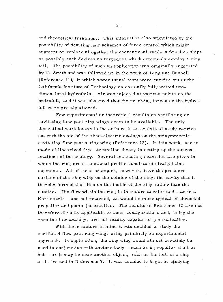
and theoretical treatment. This interest i s a lso sti-mulated by the
possibility of devising new schemes of force control which might
augment or replace altogether the conventional rudders found on ships
o r possibly such devices a s torpedoes which commonly employ a ring
tail. The possibility of such a n application was originally suggested
by K. Smith and was followed up in the work of Lang and Daybell
(Reference 11), in which water tunnel tests were car r ied out a t the
California Institute of Technology on normally fully wetted two-
dimensional hydrofoils. Air was injected a t various points on the
hydrofoil, and it was observed that the resulting forces on the hydro-
foil were greatly altered.
Few experimental o r theoretical resul ts on ventilating o r
cavitating flow past ring wings seem to be available. The only
theoretical work known to the authors i s a n analytical study car r ied
out with the aid of the rheo-electric analogy on the axisymmetric
cavitating flow past a ring wing (Reference 12). In this work, use i s
made of linearized f r e e streamline theory in setting up the approx-
imations of the analogy. Several interesting examples a r e given in
which the ring cross-sectional profile consists of straight line
segments. All of these examples, however, have the p ressure
surface of the ring wing on the outside of the ring; the cavity that i s
thereby formed thus l ies on the inside of the ring ra ther than the
outside. The flow within the ring i s therefore accelerated - a s in a
Kort nozzle - and not retarded, a s would be m o r e typical of shrouded
propeller and pump-jet practice. The resul ts in Reference 12 a r e not
therefore directly applicable to these configurations and, being the
resul ts of an analogy, a r e not readily capable of generalization.
With these factors in mind it was decided to study the
ventilated flow past ring wings using primari ly an experimental
approach. In application, the ring wing would almost certainly be
used in conjunction with another body - such a s a propeller shaft o r
hub - or it may be near another object, such a s the hull of a ship
a s i s treated in Reference 7. It was decided to begin by studying
MEASUREMENTS ON FULLY WETTED AND
VENTILATED RING WING HYDROFOILS
I. Introduction
The present repor t descr ibes a s e r i e s of experiments on
a family of simple conical ring wings in fully wetted and ventilating
flow. The general charac ter i s t ics of ring wings in uniform flow a r e
well known. Ring wings have found application in mar ine propellers,
a i rc raf t , underwater bodies such a s torpedoes, and depth bombs.
The function and description of many of these applications a r e to be
found in Reference 1. The general theoretical background of ring
wings i s dealt with in References 2 through 9. A typical and some-
what his tor ical application of ring wings to a torpedo i s given i n
Reference 10.
All of the foregoing references and applicatiorns a r e concerned
with fully wetted flow. That is , the fluid i s either a l l liquid o r a l l
air. Because of the proximity of a neighboring f r e e surface in a flow
of liquid o r perhaps by the deliberate injection of gas into a liquid
flow, a two-phase flow may take place. The cdvity of gas s o formed
may occupy only a portion of the boundary of the body s o affected, in
which case i t is called part ly cavitating (or partly ventilating if &
supply of a i r i s the cause of the cavity), o r the cavitating o r ventilating
region may entirely surround the body except 5ea r the nose. In this .L ,'a-
case the flow i s called supercavitating o r superventilaling. The object
of the present work i s to study and to t r ea t experimentally some of the
problems ar i s ing with superventilating and part ly ventilating ring
wings.
Interest in these problems i s due to the fact that this subject
has grea t intr insic value and i s a nearly unexplored field of pract ical .lr -8%
The words "ventilating" and "cavitating" a r e often used inter- changeably in the l i te ra ture and although ventilating is to be prefer red when the cavities a r e air-supported, both t e rms a r e often used to descr ibe this type of flow.
and theoretical treatment. This interest i s a l so stimulated by the
possibility of devising new schemes of force control which might
augment o r replace altogether the conventional rudders found on ships
o r possibly such devices a s torpedoes which commonly employ a ring
tail. The possibility of such a n application was originally suggested
by K. Smith and was followed up in the work of Lang and Daybell
(Reference 1 l ) , in which water tunnel tes t s were car r ied out a t the
California Institute of Technology on normally fully wetted two-
dimensional hydrofoils. Air was injected a t various points on the
hydrofoil, and i t was observed that the resulting forces on the hydro-
foil were great ly al tered.
Few experimental o r theoretical resu l t s on ventilating o r
cavitating flow past ring wings seem to be available. The only
theoretical work known to the authors i s an analytical study ca r r i ed
out with the aid of the rheo-electr ic analogy on the a ~ i s y ~ m e t r i c
cavitating flow past a ring wing (Reference 12). In this work, use i s
made of l inearized f r e e s t reaml ine theory in setting up the approx-
imations of the analogy. Several interesting examples a r e given in
which the ring cross-sect ional profile consists of s t raight line
segments. All of these examples, however, have the p res su re
surface of the ring wing on the outside of the ring; the cavity that i s
thereby formed thus l ies on the inside of the ring r a the r than the
outside. The flow within the ring i s therefore accelerated - a s in a
Kort nozzle - and not retarded, a s would be m o r e typical of shrouded
propel ler and pump-jet practice. The resu l t s in Reference 1 2 a r e not
therefore direct ly applicable to these configurations and, being the
resu l t s of an analogy, a r e not readily capable of generalization.
With these factors in mind i t was decided to study the
ventilated flow past ring wings using pr imar i ly an experimental
approach. In application, the ring wing would almost certainly be
used in conjunction with another body - suck^ a s a propel ler shaft o r
hub - o r i t may be near another object, such a s the hull of a ship
a s i s t reated in Reference 7. It was decided to begin by studying
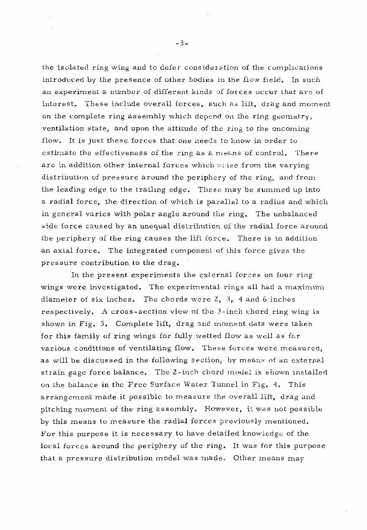
the isolated ring wing and to defer consideration of the complications
introduced by the presence of other bodies in the fiow field. Iri such
an experiment a number of different kinds of forces occur that a r e of
interest . These include overall forces , such n s lift, d rag and mornent
on the complete ring assembly which depend oa the ring geometry,
ventilation state, and upon the attitude of the ring to the oncoming
flow. It i s just these forces that one needs to know in order to
est imate the effectiveness of the sing a s a rrlez+ns of control. 'There
a r e in addition other internal forces which 3 'use f rom the varying
distribution of p r e s s u r e around the periphery of the ring, and f rom
the leading edge to the trail ing edge. These may be summed up into
a radial force, the direction of which i s paral le l to a radius and which
in general var ies with polar angle around tile ring. The unbalanced
s ide force caused by a n unequal distributio.1 of the radial force around
the periphery of the ring causes the lift force. There i s in addition
an axial force. The integrated comp0nen.t of this force gives the
p res su re contribution to the drag.
In the present experiments the external forces on four ring
wings were investigated. The exper in~en ta l r ings a l l had a m a x i m ~ ~ n ~
diameter of s ix inches. The chords were 2, 3, 4 and 6 inches
respectively. A cross-sect ion view of the 3-inch chord ring wing i s
shown in Fig. 3 . Complete lift, d rag and moment data were taken
for this family of ring wings for fully wetted flow a s w e 1 a s f u r
various conditions of ventilating flow. These fo rces were measured ,
a s will be discussed in the following section, b y means of an external
s t ra in gage force balance. The 2-inch chord model is shown installed
on the balance in the F r e e Surface Water Tunnel in Fig. 4. This
a r rangement made it possible to m e a s u r e the overall lift, d rag and
pitching moment of the ring assembly. However, ii. w a s not possible
by this means to m e a s u r e the radial forces previously mentioned.
F o r this purpose i t i s necessary to have detailed knowledge of the
local fo rces around the periphery of the ring. It was for this purpose
that a p r e s s u r e distribution model was made, Other means may
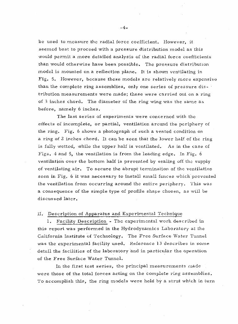
be used to measure the radial force coefficient. However, i t
seemed best to proceed with a p r e s s u r e distribution model a s this
would permit a m o r e detailed analysis of the radial force coefficients
than would otherwise have been possible. The p res su re distribution
model i s mounted on a reflection plane. It i s shown ventilating in
Fig. 5. However, because these models a r e relatively m o r e expensive
than the complete ring assemblies , only one se r i e s of p r e s s u r e dis-
tribution measurements were made; these were car r ied out on a ring
of 3 inches chord. The diameter of the ring wing was the same a s
before, namely 6 inches.
The l a s t s e r i e s of experiments were concerned with the
effects of incomplete, o r partial , ventilation around the periphery of
the ring. Fig. 6 shows a photograph of such a vented condition on
a ring of 2 inches chord. I t can be seen that the lower half of the ring
i s fully wetted, while the upper half i s ventilated. As in the case of
Figs. 4 and 5, the ventilation i s f r o m the leading edge. In Fig. 6
ventilation over the bottom half i s prevented by sealing off the supply
of ventilating a i r . To secure the abrupt termination of the ventilation
seen in Fig. 6 i t was necessary to install smal l fences which prevented
the ventilation f r o m occurring around the ent i re periphery. This was
a consequence of the simple type of profile shape chosen, a s will be
discussed la te r .
11. Description of Apparatus and Experimental Technique
1. Facili ty Description - The experimental work described in
this repor t was performed in the Hydrodynamics Laboratory a t the
California Institute of Technology. The F r e e Surface Water Tunnel
was the experimental facility used. Reference 13 descr ibes in some
detail the facil i t ies of the laboratory and in particu1.a~ the operation
of the F r e e Surface Water Tunnel.
In the f i r s t t e s t s e r i e s , the principal measurements made
were those of the total fo rces acting on the complete ring assemblies .
To accomplish this, the ring models were held by a s t ru t which in turn
was supported by a force balance. This balance ineasured the forces
and moments which acted on the models. The balance was rigidly
a.ttached to "ground" above the water surface and the support s t ru t
held the model subrr~erged in the flow. The objective of the second
se r i e s of tests was to determine the p res su re acting a t various points
on the model. A complete s e r i e s of such measurements would yield
the total p res su re distribution on the model. To accomplish this,
a rigid meta l plate was mounted a t the plane of the water surface.
The surface of this plate provided a plane of symmetry f o r the fiow,
and was hence called a "reflection" plane. In this way the F r e e
Surface Water Tunnel was converted into a closed jet tunnel having
a working section approximately 20 inches square. The model in this
case consisted of a half ring mounted on the reflection plane. Figs. 7
and 8 a r e general views of the experimental setups for the two
different tests.
Tunnel velocity was obtained by means of a mercury-biased,
water manometer which measured the p res su re f rom a total head tnhc
located upstream in the tunnel nozzle. Cavity F res su res were
rneasured using a water manometer connected to a srnall hcle dril led
in the side of the model which communicated to the cavity. Air was
bled slowly through the cavity p res su re measuring lines to insure
that they would be f r e e f rom water. This a i r flow resulted in a smal l
ze ro offset in the cavity p res su re readings which was accounted f a r i i r
the data r e d u c t i o ~ process . This ze ro shift was kept constant for each
cavity p res su re measurement by means of adjusting the a i r flow ra te
before each cavity p r e s s u r e readlng was made to a n originally pre-
determined valcre f ~ r which the p r e s s u r e drop due to this a i r flow was
known. The main cavity air supply was measured using a F i she r -
P o r t e r flow m e t e r and applying the proper correct ions for l i r : ~
p r e s s u r e and temperature. The farces were measured on the rriodels
by rrleans c.f a Task Corporation s ix component e lec t r ica l s t r a in gag?
halarlce energized by Microdot DC power supplies. Each of the Task
balance channels was displayed s n a Non-Linear Systems digitel
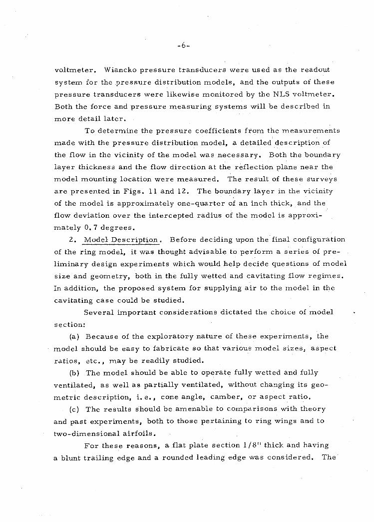
voltmeter. Wiancko p res su re t ransducers were used a s the readout
sys tem for the p res su re distribution models, and the outputs of these
p res su re t ransducers were likewise monitored by the NLS voltmeter.
Both the force and p res su re measuring sys tems will be described in
m o r e detail l a te r .
To determine the p res su re coefficients f rom the measurements
made with the p r e s s u r e distribution model, a detailed description of
the flow in the vicinity of the model was necessary. Both the boundary
layer thickness and the flow direction a t the reflection plane nea r the
model mounting location were measured. The resu l t of these surveys
a r e presented in Figs . 11 and 12. The boundary layer in the vicinity
of the model i s approximately one-quarter of an inch thick, and the
flow deviation over the intercepted radius of the model i s approxi-
mately 0.7 degrees.
2. Model Descript ion. Before deciding upon the final configuration
of the ring model, i t was thought advisable to per form a s e r i e s of pre-
l iminary design experiments which would help decide questions of model
s ize and geometry, both in the fully wetted and cavitating flow regimes.
In addition, the proposed sys tem for supplying a i r to the model in the
cavitating case could be studied.
Several important considerations dictated the choice of model
section:
(a) Because of the exploratory nature of these experiments, the
model should be easy to fabricate s o that various model s izes , aspect
ratios, etc, , may be readily studied.
(b) The model should be able to operate fully wetted and fully
ventilated, a s well as partially ventilated, without changing i t s geo-
me t r i c description, i. e., cone angle, camber, o r aspec t ratio.
(c) The resul ts should be amenable to comparisons with theory
and past experiments, both to those pertaining to ring wings and to
two-dimensional a irfoi ls .
F o r these reasons, a flat plate section 1 / 8 " thick and having
a blunt trail ing edge and a rounded leading edge was considered. The
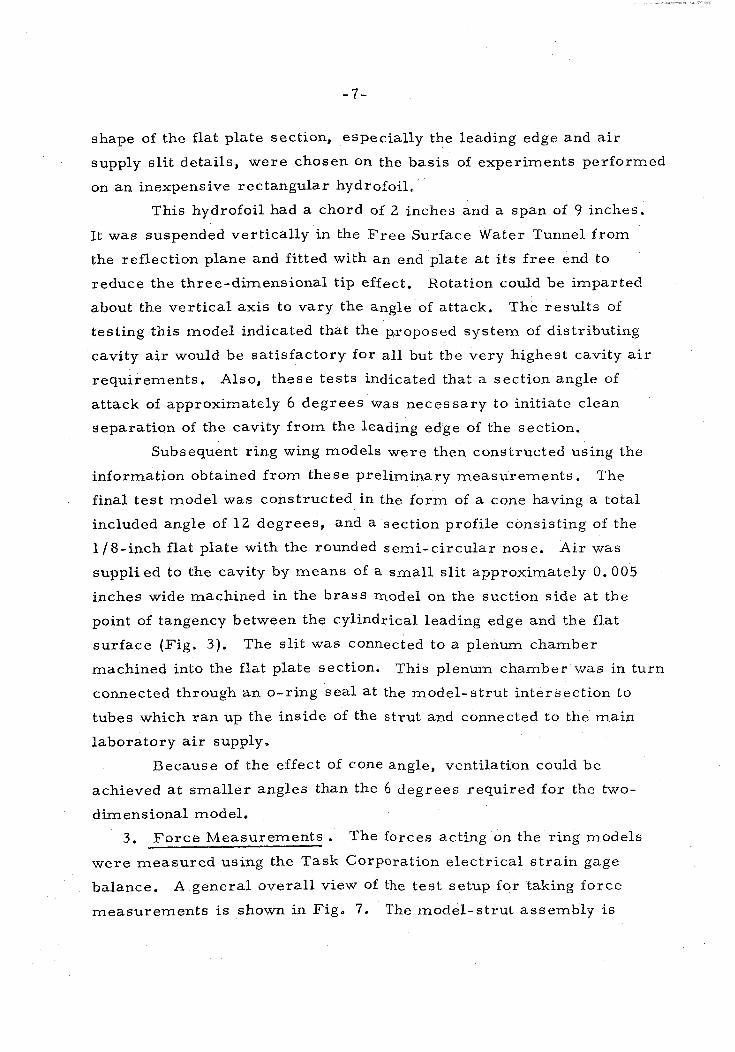
shape of the flat plate section, especially the leading edge and a i r
supply s l i t details, were chosen on the bas is of experiments performed
on an inexpensive rectangular hydrofoil.
This hydrofoil had a chord of 2 inches and a span of 9 inches.
It was suspended vertically in the F r e e Surface Water Tunnel f rom
the reflection plane and fitted with an end plate a t i t s f r e e end to
reduce the three-dimensional tip effect. Rotation could be imparted
about the ver t ical axis to vary the angle of attack. The resu l t s of
testing this model indicated that the p,roposed sys tem of distributing
cavity a i r would be sat isfactory fo r all but the very highest cavity a i r
requirements. Also, these tests indicated that a section angle of
attack of approximately 6 degrees was necessary to initiate clean
separation of the cavity f r o m the leading edge of the section.
Subsequent ring wing models w e r e then constructed using the
information obtained f r o m these preliminary measurements . The
final tes t model was constructed in the form of a cone having a total
included angle of 12 degrees, and a section profile consisting of the
1 /8-inch flat plate with the rounded semi-c i rcu lar nose. Air was
supplied to the cavity by means of a sma l l s l i t approximately 0.005
inches wide machined in the b r a s s rnodel on the suction s ide a t the
point of tangency between the cylindrical leading edge and the flat
surface (Fig. 3) . The s l i t was connected to a plenum chamber
machined into the flat plate section. This plenum chamber was in turn
connected through a n o-ring sea l a t the model-s t rut intersection to
tubes which r a n up the inside of the s t rut and connected to the main
laboratory a i r supply.
Because of the effect of cone angle, ventilation could be
achieved a t sma l l e r angles than the 6 degrees required fo r the two-
dimensional model.
3 . F o r c e Measurements . The forces acting on the ring models
were measured using the Task Corporation electr ical s t r a in gage
balance. A general overal l view of the tes t setup for taking force
measurements i s shown in Fig, 7. The model-s t rut assembly i s
attached to the force balance which is in turn supported by the angle
changing mechanism. Rotation takes place about a center arranged to
coincide with the centerline of the model. Since the balance rotates
with the model, the forces a r e measured with respect to the model
axes. These forces a r e subsequently referred to axes parallel to the
undisturbed flow upstream.
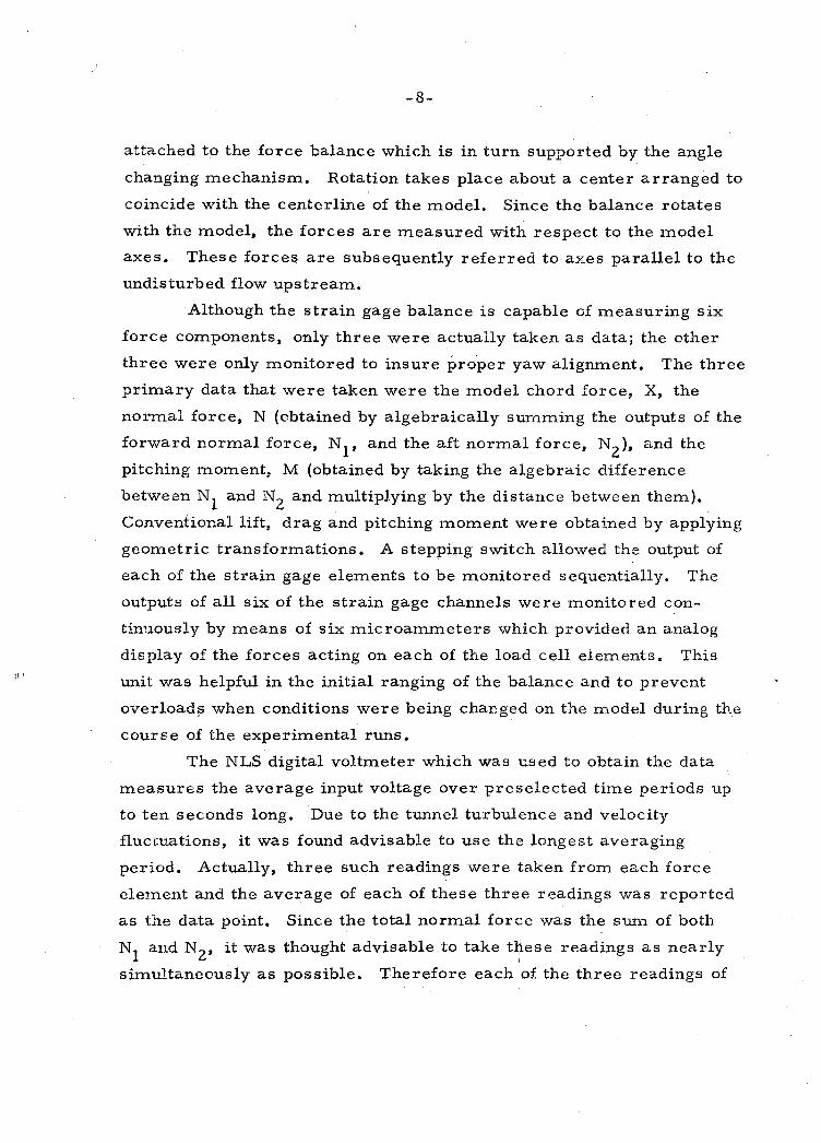
Although the s t ra in gage balance i s capable of measuring s ix
force components, only three were actually taken a s data; the other
three were only monitored to insure proper yaw alignment. The three
primary data that were taken were the model chord force, X, the
normal force, N (obtained by algebraically surnming the outputs of the
forward normal force, N and the af t normal force, N2), and the 1 pitching moment, M (obtained by taking the algebraic difference
between N and N and multiplying by the distance between them). 1 2 Conventional lift, drag and pitching moment were obtained by applying
geometric transformations. A stepping switch allowed the output of
each of the s t ra in gage elements to be monitored sequentially. The
outputs of all s ix of the s train gage channels were monitored con-
tinuously by means of s ix microammeters which provided a n analog
display of the forces acting on each of the load cell elements. This
unit was helpful in the initial ranging of the balance and to prevent
overloads when conditions were being changed on the model during the
course of the experimental runs.
The NLS digital voltmeter which was used to obtain the data
measures the average input voltage over preselected time periods up
to ten seconds long. Due to the tunnel turbulence and velocity
fluctuations, it was found advisable to use the longest averaging
period. Actually, three such readings were taken f rom each force
element and the average of each of these three readings was reported
a s the data point. Since the total normal force was the sum of both
N1 and N2, i t was thought advisable to take these readings a s nearly
sirr~ultaneousliy a s possible. Therefore each of: the three readings of
N and N (giving a total of s ix readings) were taken alternately, thus 1 2 interspersing the individual forward and aft normal force readings.
After the normal forces had been obtained, three separate readings of
the chord force were obtained and then the model was changed to a new
test condition and the process repeated. Rather than record the velocity
a t each test point, the velocity was constantly monitored and adjusted
to give the same average value over the entire se r i e s of the test run.
During the time in which the force measurements were being taken
the cavity p ressure and cavity a i r flow*rate were measured and
recorded.
F o r the case of the cavitating models, the cavity a i r supply was
determined for each configuration that would give a fully developed
cavity over the ent ire range of angles of attack. The a i r supply rate
was then readjusted to this constant value before each data point was
taken. The cavity p ressure was measured and the variation in cavi-
tation number a t constant a i r supply for each of the test conditions i s
shown in Fig. 19 . For the cavitating p ressure distribution se r i e s of
tests , a i r supply was not measured but cavity p ressure was taken a s
data. Here, two distinct values of cavitation number were obtained.
One occurred when the cavity length was adjusted to approximately
three body diameters , and the other occurred when the cavity was
allowed to grow until i t extended beyond the plate and opened to the
atmosphere, through the f ree surface. In the former case the cavi-
tation numbers obtained were on the order of: K = 0.10 and in the la t te r
case they were approximately K = 0.01.
The balance was enclosed by a stainless s tee l waterproofing
shield which had tapped holes drilled into it a t various locations along
its length to provide al ternate model mounting locations. These bolt,
locations a lso helped to locate accurately smal l brackets from which
weights could be hung to perform daily balance calibrations. In-place
balance calibration could be performed quite quickly and was repeated
each day before testing was resumed to allow for any drift that may
have occurred since the previous day's testing. In fact, the actual
drift that occurred was very small, being on the order of approximately
4 microvolts (which corresponded to . 0 4 pounds). Fig. 1 shows in
schematic form the equipment used to obtain the model force measure-
ments.
Fig. 9 shows a force model attached to the support strut. Four
different model configurations were actually tested. As previously
mentioned, they had chord lengths of 2, 3, 4 and 6 inches. The basic
ring diameter a t the leading edge was s ix inches and the total included
cone angle of all the configurations was 12 degrees. The different con-
figurations were obtained by adding detachable trailing edge sections to
a basic 2-inch chord model (Fig. 3).
To minimize any possible interference between the model
supporting s t ru t and the ring wing itself, i t was necessary to keep the
thickness of the s t ru t a t an absolute minimum consistent with the
requirements of strength and the geometrical arrangement of the tubes
which supplied the ring with ventilating a i r and measured the cavity
pressure . The manufacture of such s t ru ts is often delicate and tirne-
consuming. The present s t ru t was made quickly enough, however,
by a n electroforming process in which nickel was deposited over a
mandrel fashioned of a low melting point alloy. The mandrel which
was subsequently melted out incorporated a l l the necessary tubes and
mounting fixtures . In order to compare the results of these force tests and exper-
imental techniques with previous analytical studies that had been
evolved for thin rings of zero camber, i. e., cylindrical rings, it was
desired to c a r ry out tests on a cylindrical ring. A cylindrical ring
was constructed for this purpose which had a diameter of s ix inches
and a chord of three inches.
4. P r e s su re Distribution Measurement. In order to obtain more
detailed information about the local force coefficients on the ring wing
both in cavitating and fully wetted flow, i t was decided to construct
a p ressure distribution model which would measure the p ressure at
any desired location on both the p ressure and suction surfaces s f the
model. For the purpose of this se r i e s of tests, the reflection plane
previously mentioned was installed at the water surface in the F r e e
Surface Water Tunnel. The model projected through this reflection
plane and the central axis of the ring coincided with the reflection
plane. In this way actually only half of the model projected into the
flow. The model was se t in a mounting disk which in turn was itself
placed in a la rge circular hole in the reflection plane. The bottom
surface of the mounting disk was coincident with the bottom surface
of the reflection plane. Fig. 14 shows the model attached t o this
mounting disk. The disk could be turned about a vert ical axis and a s
a resul t the yaw angle of the model with respect to the oncoming flow
could be changed. Due to the geometry of the reflection plate-model
system, this was equivalent to varying the angle of attack of a complete
ring. Fig. 13 shows the model and mounting disk se t in the reflection
plane and the handle for setting the yaw angle. A row of eleven
p ressure taps was drilled on both the p ressure and suction surfaces
of the model in a chordwise direction. These holes communicated to
a corresponding number of 1116-inch diameter b rass tubes which were
placed circwnferentially in slots turned in the surface of the model.
These tubes broke out of the surface of the model for subsequent
attachment to l ines leading to the p ressure measuring transducers a t
a point approximately 150 degrees around the ring f rom the location
of the p ressure taps. The chordwise p ressure distributions were
obtained directly by measuring the p ressures a t each of the different
tap locations and the variation of p ressure a s a function of polar angle
(or "spanwise variation) could be determined by rotating the model
about i ts central axis in the mounting disk which was set in the
reflection plane. The p ressure taps could only be rotated from approx-
imately zero to 120 degrees. The remainder of the spanwise p ressure
distribution, that i s f rom 120 to 180 degrees polar angle, was obtained
by assuming that the p ressures at a given polar angle between 90° and 0
180 a t a positive model angle of yaw were the same a s the p ressures 0
a t a symmetrical polar angle (using the Q = 90 line a s the line of
symmetry) between zero degrees and 90 degrees for a model angle of
yaw of the same magnitude but of opposite sign. This method of
obtaining data limited the number of yaw angles (in this case only the
positive yaw angles could be used) for which a complete spanwise
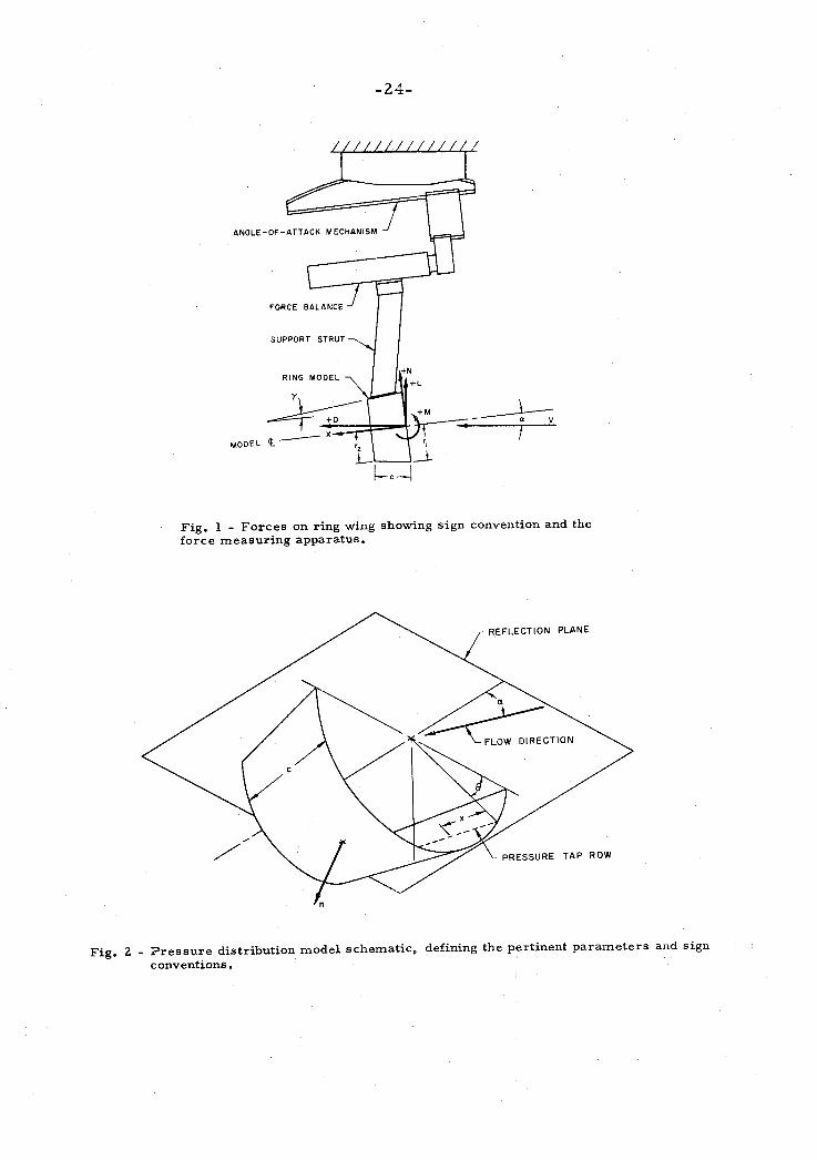
pressure distribution could be obtained. Fig. 2 shows the geometry
of the p ressure distribution model in schematic form.
Pr io r experiments performed on the complete ring used in the
force measurements indicated that a fully ventilated condition could be
maintained without using the leading edge slot but with the use of an
auxiliary a i r supply, although injection of a i r through a leading edge
slot was generally required to initiate ventilation. Because of the
comparative complexity of the pressure tap model, the leading edge
ventilation slot was omitted and ventilation was initiated by imparting
large yaw angles to the model. Once started, the ventilation could be
maintained through smal l a i r supply ports in the image plate located
near the trailing edge of the ring even though the angle of yaw of the
ring was subsequently reduced.
The pressures were measured alternately on the suction and
p ressure sides of the model in the fully wetted flow and on the pressure
side only in fully ventilated flow by means of eleven Wiancko 0-5 psi
differential p ressure transducers. The differential pressures were
measured with respect to atmosphere. The signal f rom each of the
t ransducers could be displayed sequentially by means of an eleven-
position stepping switch on the NLS digital voltmeter. Fig. 8 is a
view of the t e s t a r e a showing the model mounted in the tunnel, the NLS
voltmeter, and the power supply for energizing the t ransducers .
Fig. 15 shows the Wiancko pressure t ransducers secured to the back
of the tunnel total head manometer.
As in the force measurement runs, the tunnel velocity was
constantly monitored and adjusted to a predetermined value over the
course of a run. Likewise, cavity p ressure was measured in a manner
s imilar to that for the force runs through a hole drilled in the reflection
plane which communicated to the cavity. Cavity a i r supply ra te and
cavity length were not measured.
5. Tunnel Corrections. All of the data taken for the force
measurements were corrected for s t ru t ta re forces. To accomplish
this the model was connected to an image support system attached to
the floor of the tunnel. The image s t ru t could be rotated, in a fashion
similar to that of the main support s t rut , s o that the model angle of
attack could be changed about the model center. F o r determining the
t a re forces acting on the s trut , only the 3-inch model was used over
the same angle of attack range obtained in the force runs and the
model was run both fully wetted and ventilated, F o r the cavitating
case, cavity a i r was supplied through the main support strut, except
that the a i r to the leading edge sl i t on the ring model was supplied by
a hole drilled through the image strut and connected to the laboratory
a i r supply by means of poly-flow tubing connected to the image s t ru t
and trailing downstream in the flow to a point where i t was brought
out through the f ree surface. The s t ru t t a re forces were determined
with the s t ru t held in approximately the same position relative to the
model a s i t would have been during a normal force run, except that a
smal l gap (about .050 inches) was left between i t and the model.
Weight and buoyancy tare forces were a lso obtained a s a function of
angle of attack for a l l of the models by swinging the balance and
support s t ru t with the various models attached through the angle of
attack range both in a i r and a t operating depth in s t i l l water.
The t a re forces were a l l obtained a t the standard operating
depth of 0.675 feet and a t the standard operating tunnel speed of
18.56 feet per second. T a r e force corrections applied to data taken
a t different speeds and depths were obtained by multiplying the
measured t a r e forces by the square of the velocity ratio and the
wetted a r e a ratio for the two different t a re conditions respectively.
Interference forces due to the presence of the support s t ru t
in the fully wetted case were determined by holding the model by the
support s t ru t in the normal way and noting the change in the forces
a s the model was brought near the image s t ru t . The interference
corrections obtained in this manner were not applied to the original
data, however, both because of the small values obtained and
because of the questionable validity of applying interference data
obtained with a model having a 3-inch chord to the other models
tested in this series . Fig. 10 shows a tare run being made under
cavitating flow conditions and a t an angle of attack of zero degrees.
111. Discussion of Results
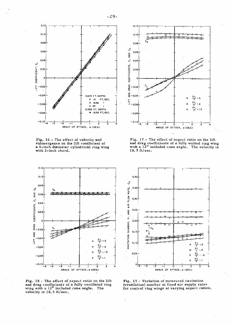
1. Overall Fo rce s . The overall experimental results obtained
a r e presented in Figs. 16 through 20. In order to compare the present
experimental resul ts with previous analytical and experimental work,
some tests were performed using a cylindrical model having a 6-inch
diameter and a 3-inch chord. These tests were a lso designed to
isolate the effects of the tunnel velocity and the f ree surface in the
absence of such complicating factors a s model cone angle, flow
separation, etc., and hence these tests were performed a t three values
of the velocity and two different submergences. It can be seen from
Fig. 16 that the main effect of velocity (or more probably Froude
number) i s to cause a slight shift in the angle for zero lift (about 1 /4
degree). Since the rings a r e relatively close to the f ree surface, it
i s possible that the proximity of the f ree surface may have an effect
on the forces experienced by the ring. It was not possible to answer
this question exhaustively due to the geometric limitations of the
working section. However, tests made on the cylindrical ring at a
somewhat reduced submergence (0.425 feet) show only minor changes
in the model forces. The slope of the lift curve i s reduced approx-
imately 4 percent and the angle for zero lift i s shifted by about 1 / 4
degree. On the basis of these findings the subsequent experiments,
except where noted, were carr ied out a t a standard tunnel speed of
18.56 f t / sec . and a t a standard submergence of 0.675 feet o r 1.22
ring diameters to the model centerline. Because of the effect of
gravity on the f ree surface of the tunnel and on the cavity formed during
tke ventilation experiments, it: can be expected that the Froude number
will be a significant modelling parameter. To vary the Froude
number without encountering severe problems of either tunnel
blockage or r ea l fluid effects predominant a t smal l Reynolds numbers,
would require a much l a rge r working section. It i s interesting to note,
however, that the standard model test conditions, i. e., 18.56 f t l sec .
and 6-inch ring diameter, would correspond to a 21 -inch diameter
ring wing a t a speed of 20.6 kts. This figure is not s o low a s to be
uninteresting in applications, and from resul ts presently to be dis-
cussed i t indicates that the effects of gravity will, i f anything, be l e s s
for prototype conditions than in the tunnel experiments.
Experimental resul ts for the conical rings a r e shown in fully
wetted flow in Fig. 17 and in fully ventilated flow in Fig. 18. The
slopes of the l i f t curves a r e higher for the fully wetted resul ts than
for the ventilating, though not by much. It will be seen that the fully
wetted cones had largely a separated flow - a condition resembling the
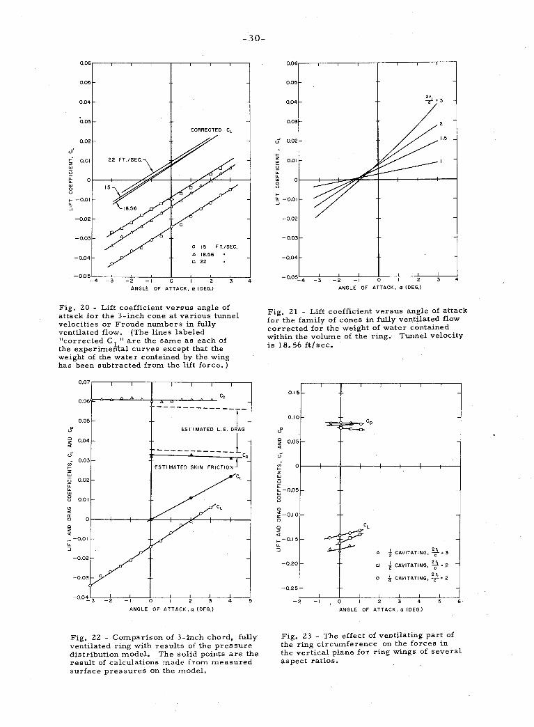
ventilated flow itself. Fig. 20 shows the effect of Froude number (or
tunnel velocity) on the aspect ratio two ring. The angle for zero lift
is clearly Froude number dependent. Since the inter ior of the ventilated
ring is filled with water and the outside of the ring is exposed to the
constant p ressure of the cavity, a major portion of the observed lift
must be due to the weight of the enclosed liquid. The resultant force
due to this liquid was reduced to coefficient form for each of the tes t
velocities and subtracted f rom the observed lift coefficients. It can be
seen that the resultant curves tend to coalesce. The data shown in
Fig. 18 have been similar ly corrected and presented in Fig. 21. The
curves thus obtained do not show zero lift a t zero angle of attack, and
indeed this ze ro lift angle does not remain exactly constant for the
various rings and tunnel velocities. This is to be expected since the
photographs of the cavities show (Figs. 4 and 10) that due to gravity,
the cavity has a pronounced vert ical asymmetry, and that because of
blockage of the flow by the cavity, the f ree surface of the tunnel
becomes appreciably distorted. It i s not yet possible experimentally
to distinguish these two effects. Nevertheless, the weight of the
water contained within the ring is the major effect.
The results of the p ressure distribution measurements which
will be presently discussed a r e compared with the full ring measure-
ments for the 3-inch (aspect ratio two) ring in Fig. 22. These results,
on the whole, agree well though they a r e not identical. This is
undoubtedly due to two different effects; the direction of gravity in
respect to the definition of angle of attack i s different in the two types
of measurements , From Figs. 1 and 2, a s well a s the photographs of
Figs. 4 and 5, it can be seen that nothing corresponding to the weight
of the enclosed liquid could a r i s e in the p ressure distribution measure-
ments. However, the two lift-slopes a r e different too. This can be
explained again by the different orientation of the gravity force and
a lso by the different conditions prevailing for tunnel interference for
the reflection plane mountings. The p ressure distributions alone do
not enable one to determine frictional drag nor the leading edge drag
in ventilation conditions (the la t te r because severe space limitations
prohibit placing a sufficient number of p ressure taps on the small
leading edge). Flat plate friction drag est imates were made of the
wetted portion of the ring a t the appropriate Reynolds number and for
the leading edge p ressure drag, i t was assumed that the drag was the
same a s on a circular cylinder the s a m e diameter a s the leading edge
and with a length equal to the circumference of the ring. These
est imates (Fig. 22) agree quite well with the measured drag force
on the 3-inch ring.
The foregoing experiments a l l deal with a basically axi-
symmetr ic flow, Two experiments were car r ied out in which only
a portion of the circumference of the ring was ventilated. The
ventilating air itself was prevented f rom issuing f rom the nose slot
by taping the leading edge, a s can be seen in Fig. 6. However,
because the basic wetted flow past these rings is separated - a t leas t
near the leading edge of the cone - the ventilation tended to migrate
around the f u l l extent of the circumference. This migra t ion was
prevented in these experiments by the attachment of fins o r fences
aligned with the f ree s t r eam direction and only la rge enough to span
the cavity a t the ring. The resultant c ross force due to the partial
ventilation is shown in Fig. 23 for the two- and three-inch rings.
It can be seen that the magnitude of the force developed by the part ial
ventilation i s equivalent to about a n angle of attack of 12 degrees on
the entire fully wetted ring. The resulting vertical force i s directed
downward f o r the ventilating condition shown in Fig. 6.
It should be remarked that had the basic ring foils not been
separated near the leading edge, there would have been no necessity
fo r the ventilation fences. The fences contribute a lift force opposite
in direction to the developed c r o s s force, s o that the resul ts of Fig. 2 3
a r e a t least conservative.
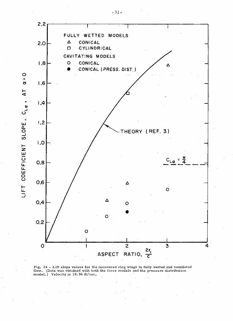
The slopes of the lift coefficient curves a t zero angle of attack
a r e summarized in Fig. 2 4 f o r a l l of the rings tested. It can be seen
that the fully wetted models of aspect ratios 1.5 and 2 approach fairly
closely the performance of the ventilated rings, suggesting s t rongly
that they a r e in fact separated flows resembling the ventilated flows
except for having a different "cavity"pressure. The highest aspect
rat io fully wetted conical ring approached Weissinger 's theoretical
values (Reference 3), and the cylindrical ring is very close to the
theory. Visual observations on the aspect ratio three conical ring
with smal l t r ace r bubbles of a i r showed that the separation bubble
a t the leading edge re-attached itself to the surface of the cone before
the t rai l ing edge, s o that values of lift slope approaching the theo-
ret ical should in fact be observed.
The lift-slope values for the fully ventilating cases appear to
approach the value of n / 4 a s the aspect ratio becomes large. It is
easy to show that this l imit is the correc t one for a ring wing of
infinitesimal chord and ze ro cavitation number and smal l cone angle.
It is , in fact, precisely one-quarter of the lift slope for the fully wetted
ring of infinite aspect ratio and, a s is well known, for smal l angles of
incidence to the flow a. cavitating flat plate hydrofoil a t ze ro cavitation
number has one-quarter the lift of a fully wetted hydrofoil. This
"one-quarter rule" i s surprisingly well followed for the complete
rings even at the aspect ratios tested, The actual ratios of the
ventilated lift slopes to those of the fully wetted theory of Weissinger
a r e 0.28, 0.29 and 0.19 for the aspect ratios 3 , 2 and 1. 5 respectively.
All of these vented flows have cavitation numbers somewhat higher than
zero (Fig. 19) which can be expected to increase the l i f t slope some-
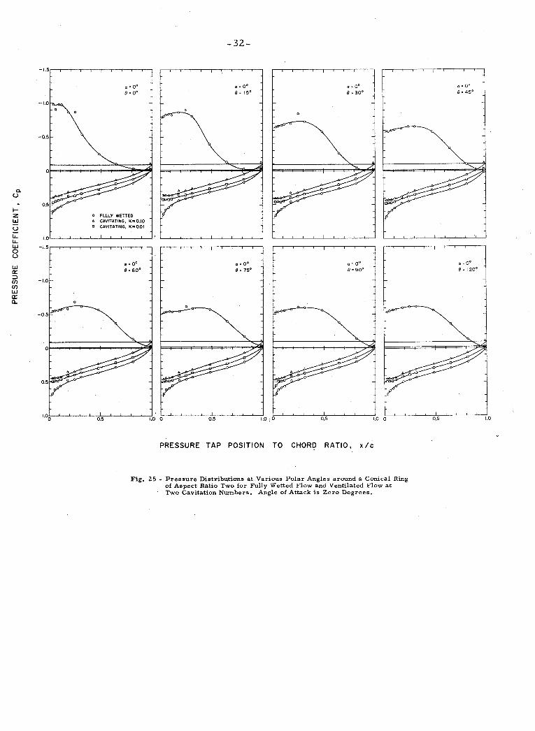
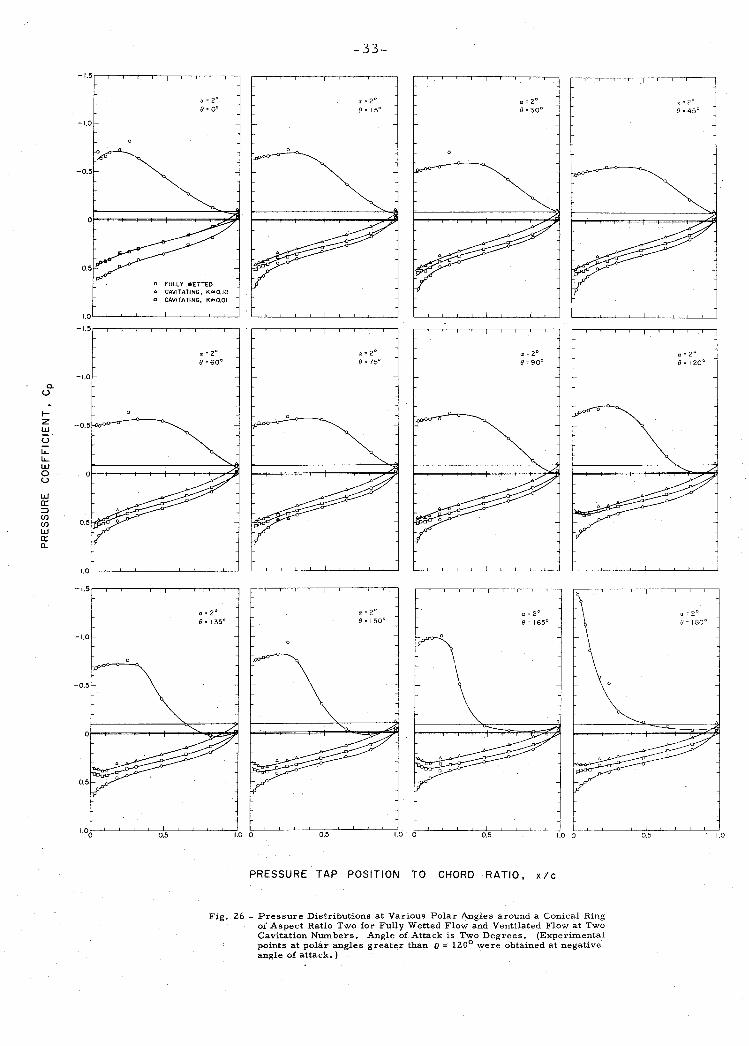
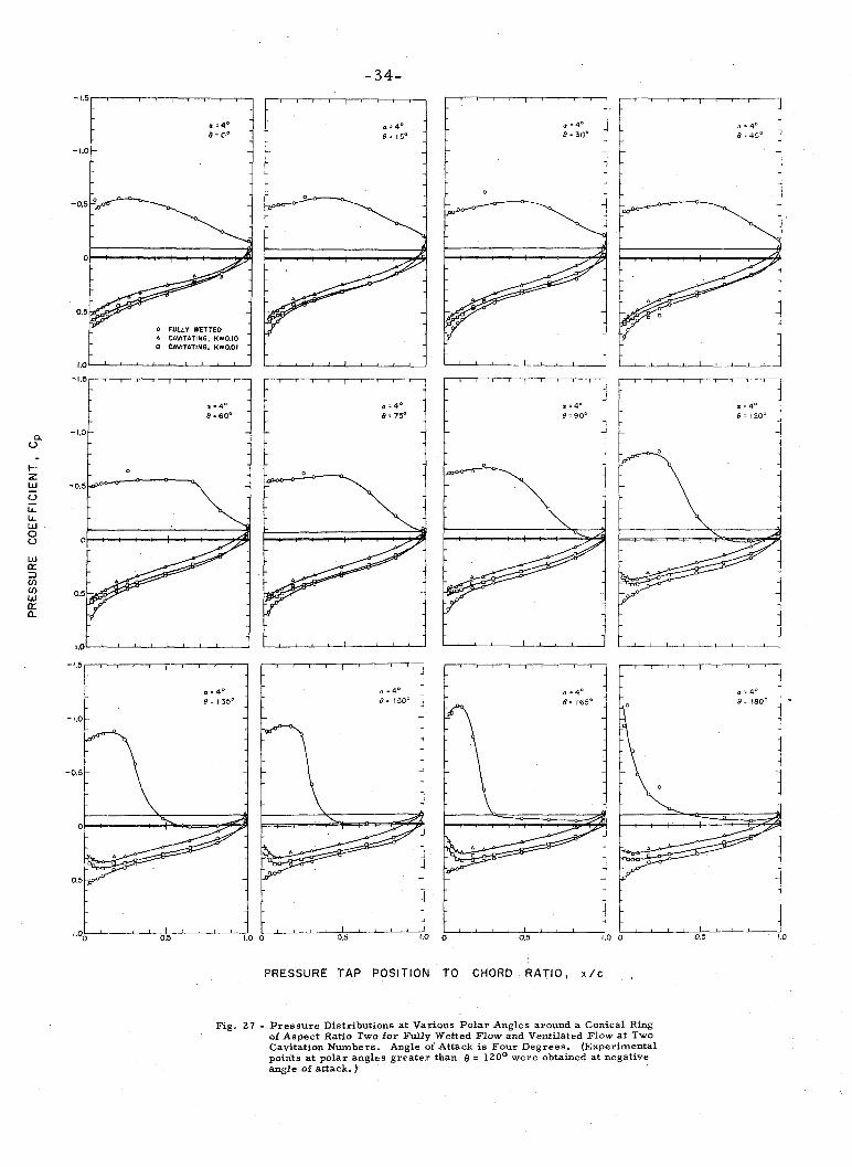
what . 2. P r e s s u r e Distributions. P r e s s u r e distributions on the aspect
ratio two ring a r e shown in Figs. 2 5 to 27. They include fully wetted
flows and two different cavitation numbers in the ventilated condition.
P r e s s u r e distributions a r e shown for severa l polar angles Q around
the ring a s sketched in Fig. 2. It i s quickly apparent that the fully
wetted distributions exhibit large regions of separation - especially
a t the la rges t angle of attack.
Each of the p ressure distribution curves was numerically
integrated to give a local normal force coefficient a s a function of the
polar angle around the ring, and these were then plotted a s a function
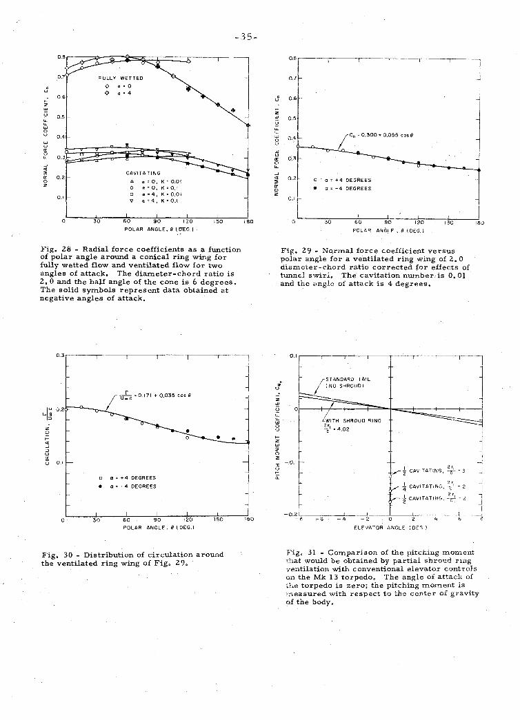
of the polar angle a s shown in Fig. 28. The effects of the tunnel swirl
can clearly be seen in this figure by examination of the curves for the
normal force coefficient a t zero angle of attack. If there had been no
swirl , these lines should be horizontal and independent of polar angle.
The amount by which they deviate from a horizontal line drawn through
their maximum point (which occurs a t a polar angle of 90 degrees)
indicates the effect of the swir l a t each polar angle, The effect of the
tunnel swir l on the normal force coefficients can be eliminated a t a l l
other angles of attack by adding to them this incremental difference a t
each polar angle. (This tacitly assumes a l inear behavior of force
coefficients with local flow angle. ) This was done for one of the
cavitating runs and a diagram sf normal force coefficient versus polar
angle which has been corrected fo r swir l a t a n angle of attack of 4
degrees and a cavitation number of 0.01 i s shown in Fig. 29. This
distribution is well fitted by a cosine curve. Velocity distributions
were calculated f rom the p ressure distributions, the effect of swir l
being treated a s above. F r o m these the distribution of bound circu-
lation was calculated and i s shown in Fig. 30. Within the accuracy
of these calculations this curve i s again adequately fitted by a cosine
curve. Such a distribution gives r i se to an upwash consistent with the
ring acting a s a minimum induced drag lifting surface (Reference 2).
A comparison can be made between the experimentally deter-
mined values of lift curve slope and those obtained in which only
bound vortex distribution i s taken into account. For this purpose we
shal l instead proceed backwards and calculate effective l i f t slope of
the two-dimensional hydrofoil section which would be needed in a s t r ip
theory and compare the resul ts s o obtained to the corresponding iso-
lated cavitating flat plate hydrofoil. It i s easy to show that the radial
inwash angle due to a sinusoidal polar distribution of bound vorticity r i s 57.3 r 12 Umc degrees. The variation in local angle of incidence
be tween 0 and 90 degrees polar angle i s thus 4 - 57.3 r / 2 Ucoc degrees
which, using the numerical resul t of Fig. 30, is 2.997 degrees. The
corresponding variation in normal force coefficient i s obtained from
Fig. 29 from which one may deduce that the appropriate value of
dCL/da for a s t r ip theory would be
dCL/d a = 0.055/(2.997)/(57.3) = 1.02 . This value is much lower than the isolated value for a cavitating flat
plate a t ze ro angle of attack, viz., ~ / 2 = 1. 57. The observed value
of lift slope on the complete ventilated r ing,from pressure distribution
data (Fig. 24) i s seen to be 0.3. This is only 22.5 percent of
Weissinger 's theory and it is only 19.8 percent of Ribner's lifting line
theory. It i s probably safe to conclude that a s the measured lift slope
of the p ressure distribution ring is low, there would be therefore an
equivalently low value for the effective dCL/da of the appropriate s t r ip
theory. Assuming that ventilation has the same effect in two dimensions
a s fo r a lifting line ring, the equivalent lift slope of a s t r ip would be
0 . 1 9 8 ~ 2 ~ = 1.24
some 20 percent higher than that calculated f rom a downwash distr i -
bution ar is ing f r o m bound vorticity alone. Although these numbers a r e

somewhat speculative in view of the tunnel swir l involved, it strongly
suggests that downwash effects ar is ing from the asymmetric cavity
should be accounted for in such flows. It i s likely that "source"
effects due to the presence of the cavity will be even more important
for partial ventilation.
As mentioned in an ear l ier section, the axisymmetric cavity
problem has yet to be solved for the present configuration. A related
problem i s the cavitating two-dimensional flow past a flat plate near
the ground. The flows a r e s imilar except that the one i s a plane flow
and the other is axisymmetric. Values of d C L / d a have been
computed for the plane flow a t zero cavitation number (Reference 14).
The two-dimensional values give a value of this parameter of about
2.4. The corresponding values for zero angle of attack on the ring
can be estimated from Fig. 28 by dividing the average normal force
coefficient by the iocal angle of incidence of the r ing, namely 6 degrees.
This gives a value of dC Id a equal to 2.8, which i s in quite reasonable L agreement with the two-dimensional value.
3. Effectiveness of the Partially Ventilated Ring. The measure-
ments of c ro s s force o r lift developed by the partial ventilation
technique shown in Fig. 2 3 can be interpreted in t e rms of a restoring
o r control moment for a specific underwater body. For the purposes
of comparison, the Mark 13 torpedo shape was chosen. The effective
moment was taken to be the observed lift force with a lever a r m equal
to the distance between the leading edge of the ring and the center of
gravity of the torpedo. The results of this calculation a r e compared
in Fig. 31 with the pitching moment a s obtained by conventional
elevator controls (this data being obtained from Reference 15). It i s
clearly evident that the partial ventilation scheme produces extremely
large control forces compared with conventional means. These forces,
in the present experiment, a r e in fact much larger than necessary.
The amount of the side force generated depends upon the fully
wetted normal force coefficient, the aspect ratio and the extent of
ventilation. As yet no theory is available to predict this resul t with
any certainty. For a f i r s t rough approximation, one may use the
local values of normal force coefficient read from Fig. 2 8 for the
ventilated and fully wetted portions of the ring and neglect completely
the influence of the upwash at these sections. The resul ts of such
an elementary calculation determined from the p ressure distributions
of the 3-inch ring a r e respectively 17 and 33 percent low, i. e.,
conservative, for the one -half and one-fourth part ial ventilation
conditions. Hardly bet ter could be expected for such a simple approx-
imation. F rom this, however, one would expect that the lift-force
would be proportional to the fully wetted normal force coefficient and
possibly a lso proportional to the extent of ventilation. No information
i s a t present available on the effect of a i r flow rate o r the lift force
developed although it would be expected that results would be s imilar
to that in Reference 11. The actual a i r flow requirement fo r venti-
lation of the aspect ratio two and three rings is somewhat l a rge r than
for plane hydrofoils; whether this amount i s "large o r small" depends
entirely upon the gases available and, a s the entrainment phenomenon
is largely a volumetric one, upon the available m a s s flow a t the
ambient p ressure level.
Acknowledgments
The authors would like to acknowledge the help of the laboratory
staff and would especially like to mention the efforts of Mess r s .
L. Whitcanack, W. Wilson, C. Eastvedt in carrying out the exper-
iments; Mrs . L. Gaard in reducing the data; and Mrs. P. Henderson
for preparation of the report.
BIBLIOGRAPHY
1. Sacks, A . H., Burnell, J. A., "Ducted Propel le rs - a Cri t ical Review of the State of the Art", Advanced Research Division of Hiller Aircraf t Corporation. Report No. ARD-232, 26 June 1959.
2. Ribner, Herbert S., "The Ring Wing in Nonaxial Flow", J. Aero. Sci., Vol. 14, 1947, p. 529.
3. Weissinger, J . , "Some Results f rom the Theory of the Ring Wing in Incompressible Flow", Trans. f rom Advances in Aeronautical Sciences, Proceedings of F i r s t International Congress in the Aeronautical Sciences, Madrid, 8- 13 September 1958, Vol. 2, pp. 798-831.
4. Kriebel, A. R., Sacks, A. H., Nielsen, J. N., "Theoretical Investigation of Dynamic Stability Derivatives of Duc ted P r o - pellers", Vidya Technical Report No. 63-95, 9 January 1963.
5. Kriebel, A. R., "Theoretical Investigation of Static Coefficients, Stability Derivatives, and Interference for Ducted Propel lers" , Vidya Report No. 112, March 31, 1964.
6. Kriebel, A. R., "Theoretical Stability Derivatives fo r a Ducted Propeller", Vidya Inter im Report, October 18, 1963.
7. Kriebel, A. R., "Interference between a Hull and a Stern-Mounted Ducted Propel ler" , Vidya Report No. 161, September 30, 1964.
8. Weissinger, J. , "Ring Airfoil Theory, Problems of Interference and Boundary Layer", Ins titut f c r Angewandte Mathematik de r Technischen Hochschule, Karlsruhe, Germany, January 1959.
9. Reynolds, Jack F., "Lifting Surface Theory Applied to Isolated Ring Wings a t Angle of Attack", NAVWEPS Report 8401, NOTS T P 3322, November 1963.
10. Levy, J. , Knapp, R. T., "Water Tunnel Tes ts of the MK 13- 1, MK 13-2 and MK 13-2A Torpedoes with Shroud Ring Tails", California Institute of Technology, HML Report No. ND-15.1, November 24, 1943.
11. Lang, T. G., Daybell, D. A., "Water Tunnel Tes ts of Three Vented Hydrofoils in Two-Dimensional Flow", J. of Ship Research, Vol. 5, No. 3, December 1961.
12. Luu, T. S., "Analytical Study and Rheoelective Simulation of Supercavitating Flows around Two and Three-Dimensional Hydrofoils", B. A. R. A. (47 Avenue Victor-Cresson, Issy-les- Moulineaux), December 1961.
13. Knapp, R. T., Levy, J . , OINeill, J . P. and Brown, I?. B., "The Hydrodynamics Laboratory a t the California Institute of Technology", Trans. A . S. M. E., Vol. 70, No. 5, July 1948, pp. 437-457.
14. Ai, D. K. , Acosta, A. J., Harr ison, Z. L., "Linearized Theory of a Two-Dimensional Planing Flat Plate in a Channel of Finite Depth - I", Hydrodynamics Laboratory, California Institute of Technology, Report No. E-110.2, April 1964.
15. Grady, R. J . , "Hydrodynamic Coefficients of Torpedoes, P a r t I", NAVORD Report No. 544, 16 November 1953.
ANGLE-OF-ATTACK MECHANISM ' w FORCE BALANCE ? SUPPORT STRUT -.I I
RING MODEL
Fig. 1 - Forces on ring wing showing sign convention and the force measuring apparatus.
Fig. 2 - Pressure distribution model schematic, defining the pertinent parameters and sign conventions.
H ,-HOLLOW SUPPORT STRUT
DISTRIBUTION PLENUM
2 IN. CHORD
LTRA~LING EDGE FILLER RING
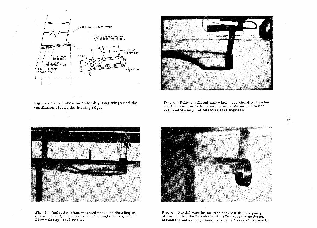
Fig. 3 - Sketch showing a s s e m b l y r ing wings a n d the venti lat ion s lo t a t the leading edge.
Fig. 4 - Fully ventilated ring wing. The chord is 3 inches and the diameter is 6 inches. The cavitation number i s 0.13 and the angle of attack i s zero degrees.
Fig. 5 - Reflection plane mounted p ressure distribution model. Chord, 3 inches, k = 0.10, angle of yaw, 4'. Flow velocity, 18.6 ft lsec.
Fig. 6 - Part ia l ventilation over one-half the periphery of the ring for the 2-inch chord. (To prevent ventilation around the entire ring, small auxiliary "fences" a r e used.)
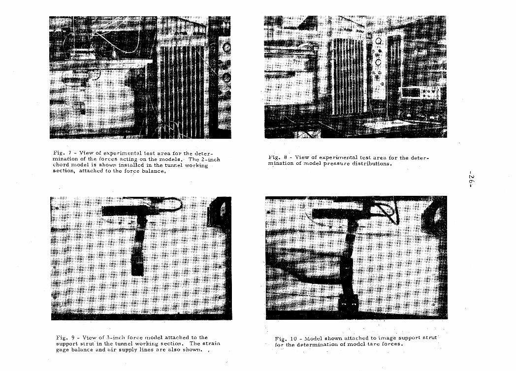
Fig. 7 - View of experimental tes t a r e a for the deter - mination of the forces acting on the models. The 2-inch chord model i s shown installed in the tunnel working section, attached to the force balance.
Fig. 8 - View of experimental tes t a r e a for the deter - mination of model p res su re distributions.
Fig. 9 - View of 3-inch force model attached to the support s t ru t in the tunnel working section. The s t r a in gage balance and a i r supply lines a r e a lso shown. ,
Fig. 10 - Model shown attached to image support s t ru t for the determination of model t a r e forces.
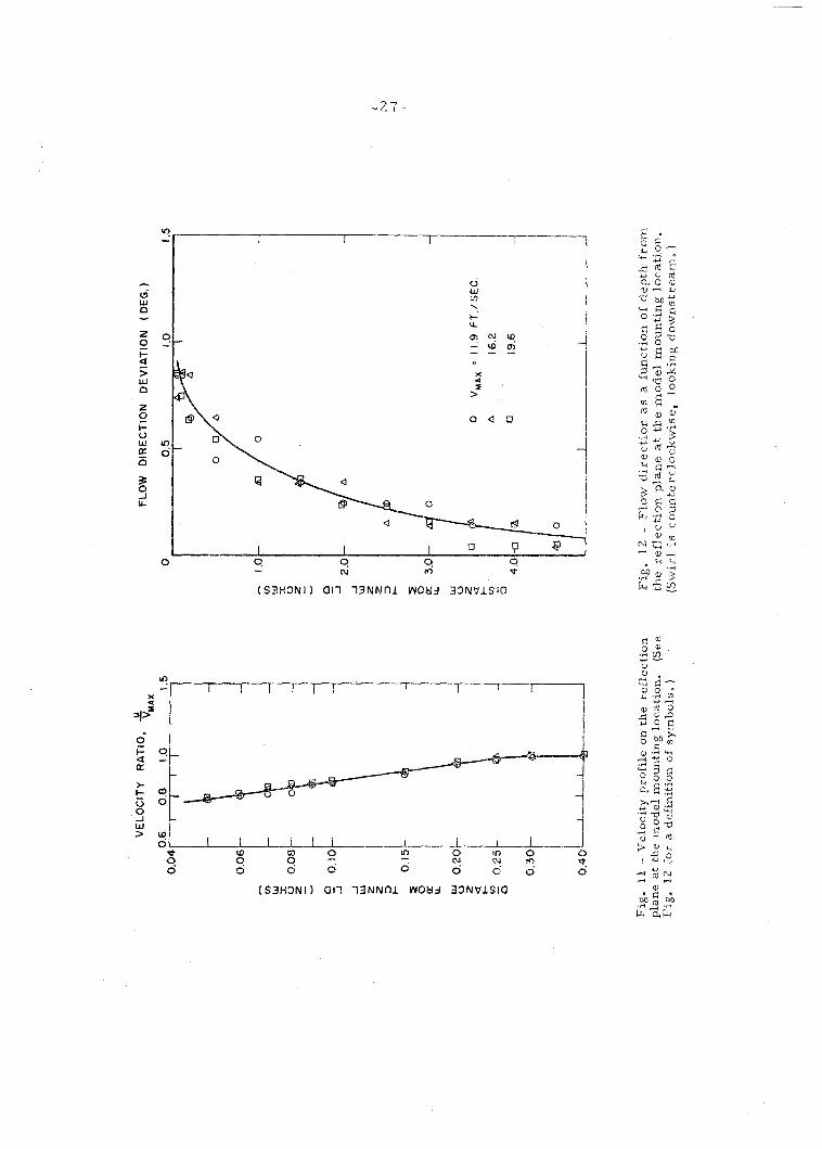
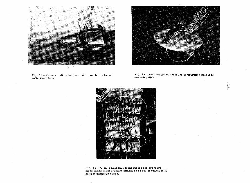
Fig. 13 - P r e s s u r e distribution model mounted in tunnel reflection plane.
Fig. 14 - Attachment of pressure distribution model to mounting disk.
Fig. 15 - Wianko p ressure transducers for p ressure distributioxi measurement attached to back of tunnel total head manometer board.
0675 FT. DEPTH
0.425 FT. DEPTH
ANGLE OF ATTACK. a (DEG.)
Fig. 16 - The effect of velocity and submergence on the lift coefficient of a 6-inch diameter cylindrical ring wing with 2-inch chord.
ANGLE OF ATTACK. a (DEG.)
ANGLE OF ATTACK. a (DEG)
Fig. 17 - The effect of aspect rat io on the lift and drag coefficients of a fully wetted ring wing with a 12O included cone angle. The velocity i s 18.5 f t fsec .
0.05 -
2 r A = I
O14 -; -A -I o 1 A 4
ANGLE OF ATTACK, a ( D E G )
Fig. 18 - The effect of aspect ra t io on the lift Fig. 19 - Variation of measured cavitation and d rag coefficients of a fully ventilated ring (ventilation) number a t fixed a i r supply ra tes wing with a 12O included cone angle. The for conical ring wings a t varying aspect ratios. velocity i s 18.5 f t / sec .
t CORRECTED C, i
-0.051 , - 4 - 3 - 2 - 1 0 1 2 3 4
ANGLE OF ATTACK. a (DEG.) ANGLE OF ATTACK. a (DEG.)
Fig. 20 - Lift coefficient versus angle of attack for the 3-inch cone a t various tunnel Fig. 21 - Lift coefficient versus angle of attack
velocities o r Froude numbers in fully for the family of cones in fully ventilated flow
ventilated flow. (The lines labeled corrected for the weight of water contained
"corrected C " a r e the same a s each of within the volume of the ring. Tunnel velocity
the exDerimeha1 curves except that the i s 18.56 f t l sec .
weigh; of the water contained by the wing has been subtracted from the lift force. )
-O.O4_3 - 2 - 1 0 1 2 3 4 5
ANGLE O F A T T A C K . a IDEG.)
,-0.15
'L A CAVITATING, : 3
$ CAVITATING. = 2
7 CAVITATING. $ = 2
- 0 . 2 5
- 2 - 1 0 1 2 3 4 5 6
ANGLE OF ATTACK, a (DEG )
Fig. 22 - Comparison of 3-inch chord, fully Fig. 23 - The effect of ventilating part of ventilated ring with results of the p ressure the ring circumference on the forces in distribution model. The solid points a r e the the vertical plane for ring wings of several
resul t of calculations made f rom measured aspect ratios. surface p ressures on the model.
F U L L Y W E T T E D M O D E L S
CONICAL Q C Y L I N D R I C A L
CAVlTATlNG MODELS
0 CONICAL 9 CONICAL (PRESS. DIST. )
THEORY ( REF. 3)
-
'1 ASPECT RATIO, 7
Fig. 2 4 - Lift slope values for the measured ring wings in fully wetted and ventilated flow. (Data was obtained with both the force models and the pressure distribution model. ) Velocity i s 18.56 f t l sec .
-
0 FULLY WETTED A CAVITATING. K * 0 1 0 D CAVITATING. K - 0 0 1 '
I 0 " " ~ " " '
PRESSURE T A P POSITION TO CHORD RATIO, x / c
Fig. 25 - Pressure Distributions at Various Polar Angles around a Conical Ring of Aspect Ratio Two for Fully Wetted Flow and Ventilated Flow at Two Cavitation Numbers. Angle of Attack i s Zero Degrees.
-0.5
0
0 5
0 FULLY WETTED 6 CAVITATING. K m O I O 0 CAVITATING. K a O O l
1 0
PRESSURE T A P P O S I T I O N T O CHORD R A T I O , x / c
Flg. 26 - Pressure Dislributlons at Varlous Polar Angies around a Conical Rlng of Aspect Ratlo Two for Fully Wetted Flow and Ventilated Flow at Two Cavrtation Numbers. Angle of Attack i s Two Degrees. (Experlrnental points at polar angles greater than fj = 1 2 0 ~ were obtalned at negatlve angle of attack. )
-
0 FULLY WETTED 6 CAVITATING, K r O l O 0 CAVITATING. K-0.01 -
PRESSURE T A P POSITION TO CHORD RATIO, x / c .
Fig. 27 - Pressure Distributions at Various Polar Angles around a Conical Ring of Aspect Ratio Two for Fully Wetted Flow and Ventilated Flow at Two Cavitation Numbers. Angle of Attack i s Four Degrees. (Experimental points at polar angles greater than = 120° were obtained at negative angle of attack. )
F U L L Y WETTED
0 m = O
0 ""P 6 0 m . 4
i
C A V I T A T I N G
A 0 = O . K = O . O I 0 a = O . K = O I
I I I I I I 0 3 0 6 0 90 1 2 0 1 5 0 I 8 0
POLAR ANGLE, B ( V E G
Fig. 28 - Radial force coefficients a s a function of polar angle around a conical ring wing for fully wetted flow and ventilated flow for two angles of attack. The diameter-chord ra t io i s 2.0 and the half angle of the cone i s 6 degrees. The solid symbols represent data obtained a t negative angles of attack.
1 m = +; OEGREEsl , lo a = - 4 DEGREES
0 3 0 6 0 9 0 I 2 0 1 5 0
POLAR ANGLE, 9 ( D E G )
Fig. 30 - Distribution of circulation around the ventilated ring wing of Fig. 29.
r C , = 0 . 3 0 0 + 0 .055 cost3
a = -4 DEGREES
I I 0 3 0 6 0 9 0 120 130 180
POLAR ANGLE . B (OEG )
Fig. 29 - No.rma1 force coefficient versus polar angle for a ventilated ring wing of 2.0 diameter-chord ratio corrected for effects of tunnel swirl. The cavitation number i s 0.01 and the angle of attack i s 4 degrees.
STANDARD T A I L
s 0
i
LU 0 0
ti. W
0 0
I- 61
2 r I & CAViTATlNi- . -$ - 2 - 1
CAVITATING, 2 - 2 1 I
-0.2' I I I I I - _ ~ 1 _ - - 1 -8 - 6 - 4 - 2 0 2 4 b E
ELEVATOR ANGLE ( O E S )
Fig. 31 - Comparison of the pi tchug moment +hat would be obtained by partial shroud ring -/entilation with conventional elevator controls on the Mk 13 torpedo. The angle of attack of he torpedo i s zero; the pitching moment i s measured with respect to the center of gravity of the body.
DISTRIBUTION LIST
Agency Copies
Chief, Bureau of Naval Weapons Department of the Navy, Washington, D. C. 2 0360
Attn: Code RRRE-4 Code RUTO-32 Code RAAD-3 Code DLI-3
Commanding Officer and Director David Taylor Model Basin, Carderock, Maryland
Attn: Code 601 Code 526
Commander, Naval Missile Center, Point Mugu, California A ttn: Technical Library 1
Commander, Naval Ordnance Test Station Inyokern, China Lake, California
A ttn: Technical Library
Commander, Naval Ordnance Test Station Pasadena Annex, Pasadena, California
Attn: Code P80 Code P5006
Commander, Naval Ordnance Laboratory White Oak, Silver Spring, Maryland
Attn: Code 591 Code 750
Commanding Officer, Naval Underwater Ordnance Station Newport, Rhode Island
Officer in Charge, Naval Aircraft Torpedo Unit U. S. Naval Air Station, Quonset Point, Rhode Island
Attn: R. Crowell 1
Commanding Officer and Director Naval Electronics Laboratory, San Diego 52, California 1
Commanding Officer, Naval Torpedo Station, Keyport, Wash. Attn: J. Mason 1
Commander, Naval Weapons Laboratory, Dahgren, Va. Attn: Technical Library 1
DISTRIBUTION LIST (continued)
Chief of Naval Research, Department of the Navy Washington, D. C. 20360
Attn: Code 438 Code 466
Chief, Bureau of Ships, Department of the Navy Washington, D. C. 20360
Attn: Code 421
U . S. Naval Academy, Annapolis, Maryland , Attn: Library 1
U. S. Naval Research Laboratory, Washington, D. G. 20390 Attn: Library 1
U. S. Naval Underwater Sound Laboratory For t Trumbull, New London, Connecticut
A ttn: Library
Superintendent, U. S. Naval Postgraduate School Monterey, California
A ttn: Library
Air Force Office of Scientific Research (SREM) Washington, D. C. 20333
National Aeronautics and Space Adminishation Washington, D. C. 20546
Commander, Defense Documentation Center Cameron Station, Alexandria, Virginia 2231 4
National Science Foundation, Washington, D. C. 2 0550 , 1
National Bureau of Standards, Fluid Mechanics Section Washington, D. 6.
Attn: Dr. G. B. Schubauer 1
Director, Applied Physics Laboratory, The Johns Hopkins University, Silver Spring, Maryland
A ttn: Library
Alden Hydraulic Laboratory Worcester Polytechnic Institute, Worcester 9, Mass.
Attn: L. J. Hooper 1
Davidson Laboratory Stevens Institute of Technology, Hoboken, New Je r sey
Attn: A. Suarez
DISTRIBUTION LIST (continued)
Ordnance Research Laboratory Pennsylvania State University, State College, Pennsylvania
Attn: G. F. Wislicenus 1
Hydrodynamics Laboratory, Department of Naval Architecture and Marine Engineering, Massachusetts Institute of Technology, Cambridge 3 9 , ,Mass.
Attn: Library 1
Advanced Sys tems Engineering Westinghouse Elec t r ic Corporation, Sunnyvale, California
A ttn: M. S. Macovsky I
Aerojet General Corporation, Azusa, California Attn: C. A. Gongwer
American Machine and Foundry Company P. 0. Box 187, Station F, Buffalo 12, New York
Attn: G. F. Hussey
Clevite Ordnance, Division of Clevite Corporat i on 540 E. 105th Street , Cleveland 8, Ohio
Attn: T. Lynch 1
E a s t e r n Research Group, 120 Wall Street, New York 5, N. Y. Z
Goodyear Aircra.ft Corporation, Akron 15, Ohio Attn: R. R . F isher
Grumman Aircraf t Engineering Corporation Bethpage, Long Island, New York
Attn: Research Department
Hydronautics, Inc., Laurel , Maryland Attn: P. Eisenberg
United Aircraf t Corporation Research Laborator ies Eas t Hartford 8, Connecticut
Attn: F. S. Owen
Underwater Launch Department Lockheed Missi le and Space Division, Sunnyvale, Calif,
Attn: R. W. Kermeen
Hydrodynamics Laboratory GD/Contair San Diego 12, California
Attn: R. H. Oversrnith

DISTRIBUTION LIST (continued)
Therm Advanced Research Division, Therm, Inc. Ithaca, New Yark
Attn: A. Ritter
Vidya Division, Itek Corporation 1450 Page Mill Road, Pa lo Alto, California
Attn: J. N. Nielsen
Unclassified Security Classification
JMENT CONTROL DATA - RhD
Measurements on Fully Wetted and Ventilated Ring Wing Hydrofoils
4. DESCRIPTIVE NOTES (Type of report and lncluelve dates)
5. AUTHORfS) (Last name. ffrat name, Initial)
Acosta, Allan J., Bate, J r . , E. R., and Kiceniuk, T a r a s
6. REPQ'RT DATE 7 0 . T O T A L NO. O F PAGES 7 6 . NO. O F REFS
June 1965 44 15
I LIa. CONTRACT OR GRANT NO.
Nonr 220(54) - 61212 b. PROJECT NO.
9 0 . ORIC(INATORbS R E P O R T NUMBER(S)
E-138.1
O b OTHER R E P O R T NO@) ( A n y otharnumbsn that may bo aeelpnod Ihls report)
d.
10. A V A IL ABILITY/LIWITATION NOTICES
I Qualified r eques t e r s m a y obtain copies of this r epo r t f r o m DDC
11. SUPPLEMENTARY NOTES I 12. SPONSORING MILITARY ACTIVITY
Department of the Navy, Bureau of Nava Weapons, Fluid Mechanics and Flight
1 ~ ~ n i m i c s Branch 13. ABSTRACT
F o r c e measu remen t s and visual observations w e r e made in a wate r tunnel on fully wetted and ventilated flows past a family of conical ring wings having a flat plate sect ion geometry. The d iameter -chord ra t io was var ied f rom one to three , and the total included cone angle was 1 2 degrees . The fully wetted flows a l l exhibited separa t ion f r o m the leading edge except fo r the l a r g e s t d iameter -chord ratio, a resu l t which was in agreement with previous work. The effect of ventilation i s to reduce markedly the l i f t curve slope. P r e s s u r e distr ibution measu remen t s w e r e a l s o made under ventilating conditions f o r one m e m b e r of thi! s e r i e s . The effect of ventilation over only a portion of the c i r cumfe rence of the ring was a l s o br ief ly investigated. La rge c r o s s f o r c e s w e r e developed by such ventilation and some compar i sons a r e made between this method of obtaining control fo rces and m o r e conventional methods.
Control Surfaces
1. ORIGINATING ACTIVITY: Enter the name and address Imposed by security claseification, using standard etatementn of the contractor, subcontractor, grantee, Department of De- such as: fense activity or other organization (corporate author) i ssuing (1) "Qualified requesters may obtain copies of t h i s
report from DDC" 2a. REPORT SECURITY CLASSIFICATION: Enter the over- (2) "Foreign announcement end dieneminatlon of th l r all security c lass i f ica t ion of the report. Indicate whether report by DDC i s not authorized." "Restricted Data" i s included. Marking is to b e in accord- ance with appropriate security regulations. (3) "U. S. Government agencies may obtatn copies of
th is report directly from DDC. Other qualified D m 26. GROUP: Automatic downgradlng is specified in DoD Di- use r s shal l request through rective 5200.10 and Armed Forces Industrial Manual. Enter the group number. Also, when applicable, show that optional 1 markings have been used for Group 3 and Group 4 a s author- (4) "U. S. military agencies may obtain cop ies of thla ized.
I report directly from D D C Other qualified u s e r s , 3. REPORT TITLE: Enter the complete report t i t le i n dl shal l request through capital letters. T i t l e s i n all c a s e s should b e unclassified. I I ' If a meaningful t i t le cannot be se lec ted without c lass i f ica- tion, show t i t le c lass i f ica t ion i n a l l cap i t a l s i n parenthes is (5) "All distribution of th i s report i s controlled. Qual- immediately following the title. I ifled DDC users shall request through
4. DESCRIPTIVE NOTES: If epproprlate, enter the type of report, e.g., interim, progress, summary, annual, or final. Give the inclusive da te s when a s*cific reporting period is covered.
8 8
If !he report h a s been furnished to the Office of Technical Services, Department of Commerce, for s a l e to the public, indl- c a t e th i s fact and enter the price, if known
5. AUTHOR(S): Enter the name(s) of authods) a s Shown o n 11. S U P P L M E N T A R Y NOTES: Use for additional ewplana-" or in the report. Enter l a s t name, first name, middle initial. tory notes. If xil i tary, show rank and branch of service. T h e name of the principal -:lthor is an absolute minimum requirement 12. SPONSORING MILITARY ACTIVITY: Enter the name of
the departmental project office or laboratory sponsoring (pay- G. REPORT DATf: Enter the da te of the report a s day, ing for) the research and development. Include address. month, year; or month, year. If more than one date appears on the report, u s e da te of publication. 13 ABSTRACT: Enter an abs t rac t giving a brief and factual
summary of the document indicative of t he report, even though 78. TOTAL NUMBER O F PAGES: T h e total page count i t may a l s o appear elsewhere in the body of the t e c h n ~ c s l re- should follow normal pagination procedures, i.e., enter the port. If additional s p a c e IS requited, a continuatron s h e e t sha l l number of pages containing information. be attached. 76. NURIbER O F REFERENCES Enter the total number of references cited in the report.
8a. CONTRACT OR GRANT NUMBER: If appropriate, enter the applicable number of the contract or grant under which the report was wri t ten
86, 8c, & ad. PROJECT NUMEjER: Enter the appropriate military department identification, such a s project number, subproject number, sys tem numbers, task number, etc.
98. ORIGINATOR'S REPORT NUMBER(S): Enter t he offi- c ia l report number by which the document will b e identified and controlled by t h e origtnating activity. T h i s number muat b e unique to this report.
96. OTHER REPORT NUMBER(S): If t h e report has been assigned any other rcpcrt numbers ( e ~ t h e r by the orlginetor or by the sponsor), a l so enter t h i s number(s).
10. AVAIEABILITY/LIMITATIQN NOTICES: Enter any lim- i tations on further dissemination of the report, other than those
It 1s highly des t rable that the abstract of c I ~ s 6 1 f i e d reports be unclassified. Each paragraph of the abstract shal l end wlth an indication of the m~l t tary security c l a s s t f ~ c a t i o n of the in . formation in the paragraph, represented a s (Ts). ( s ) , ( C ) , o r ( U J
There i s no Irmitation on the length of the abstract. t i o w - ever, the suggested length IS from 150 19 225 words.
14. KEY WORDS: Key words are tcchnlcally meaningful tern18 or short phrases that c h a r a c t e r ~ z e a rrport and may be used Y R
index entr ies for cataloging the report. Key words must be se lec ted s o that no aecurtty c l a s s l f ~ c a t i o n is required. ldenti- f ~ e r s , such a s equipment model deslgmatton, trade name, mill taq project code name, geographic location, may be used a s key words but will be followed by an indication of t e c h n ~ c a l con- text. The rtlssignment of l inks, rules, and weights is opttonril
Security Classification


![Wetted Mobile Packed Bed [Compatibility Mode]](https://static.cupdf.com/doc/110x72/577c77921a28abe0548ca292/wetted-mobile-packed-bed-compatibility-mode.jpg)