IndexProject Guides
L23/30H
Text Index Drawing No.
Introduction I 00
Introduction to project guide I 00 00 0 1643483-5.2 Key for engine designation I 00 05 0 1609526-0.5 Designation of cylinders I 00 15 0 1607568-0.2 Code identification for instruments I 00 20 0 1687100-5.2 Basic symbols for piping I 00 25 0 1631472-4.1
General information D 10
List of capacities D 10 05 0 1607532-0.7 List of capacities D 10 05 0 1699151-1.0 Engine performance D 10 10 0 1643447-7.0 Engine performance D 10 10 0 1624432-9.3 Heat balance D 10 20 0 1683389-5.0 Heat balance D 10 20 0 1683390-5.0 Heat balance D 10 20 0 1624434-2.1 Description of sound measurements D 10 25 0 1609510-3.4 Sound measurements D 10 25 0 1613430-7.3 Exhaust gas emission D 10 28 0 1624461-6.2 NOx Emission D 10 28 0 1687135-3.0 Moment of inertia D 10 30 0 1607591-7.4 Overhaul recommendations D 10 35 0 1607531-9.4 Overhaul recommendations D 10 35 0 1699106-9.0
Basic Diesel Engine B 10
General description B 10 01 1 1613472-6.6 Cross section B 10 01 1 1607529-7.2 Main particulars B 10 01 1 1609517-6.8 Dimensions and weights B 10 01 1 1613473-8.5 Centre of gravity B 10 01 1 1631458-2.0 Material specification B 10 01 1 1613423-6.3 Overhaul areas B 10 01 1 1624445-0.4 Low dismantling height B 10 01 1 1631462-8.0 Engine rotation clockwise B 10 11 1 1607566-7.1
Fuel Oil System B 11
Internal fuel oil system B 11 00 0 1613570-8.7 Fuel oil diagram B 11 00 0 1624468-9.8 Fuel oil specification B 11 00 0 1609529-6.4 Fuel oil quality B 11 00 0 1693520-5.2 Fuel oil cleaning recommendations B 11 00 0 1655267-1.3 Specific fuel oil consumption SFOC B 11 01 0 1607542-7.6
Lubrication Oil System B 12
Internal lubricating oil system B 12 00 0 1613429-7.6 Prelubricating pump B 12 07 0 1624477-3.5 Lubricating oil specification B 12 15 0 1609531-8.7 Treatment of lubricating oil B 12 15 0 1643494-3.5
Cooling Water System B 13
Index Project Guides
L23/30H
Text Index Drawing No.
Freshwater system treatment B 13 00 0 1609571-3.4 Internal cooling water system B 13 00 0 1613439-3.1 Internal cooling water system 1 B 13 00 1 1613575-7.3 Internal cooling water system 2 B 13 00 2 1613576-9.3 Design data for external cooling water system B 13 00 0 1613441-5.2 External cooling water system B 13 00 0 1613442-7.0 One string central cooling water system B 13 00 1 1624464-1.0 Preheater arrangement in high temperature system B 13 23 1 1613485-8.5
Compressed Air System B 14
Compressed air system B 14 00 0 1613580-4.4 Compressed air system B 14 00 0 1624476-1.1
Combustion Air System B 15
Combustion air system B 15 00 0 1613581-6.5 Engine room ventilation and combustion air B 15 00 0 1699110-4.0 Water washing of turbocharger - compressor B 15 05 1 1639499-6.0 Lambda controller B 15 11 1 1693567-3.0
Exhaust Gas System B 16
Exhaust gas system B 16 00 0 1609535-5.2 Dry cleaning of turbocharger - turbine B 16 01 1 1607599-1.4 Water washing of turbocharger - turbine B 16 01 2 1607517-7.5 Position of gas outlet on turbocharger B 16 02 0 1613417-7.3 Silencer without spark arrestor, damping 25 dB (A) E 16 04 2 1609574-9.4 Silencer without spark arrestor, damping 35 dB (A) E 16 04 3 1609577-4.4 Silencer with spark arrestor, damping 25 dB (A) E 16 04 5 1609580-8.4 Silencer with spark arrestor, damping 35 dB (A) E 16 04 6 1609584-5.4
Speed Control System B 17
Starting of engine B 17 00 0 1607583-4.3 Governor B 17 01 4 1679743-4.2 CoCoS P 17 40 0 1683324-8.2
Monitoring Equipment B 18
Standard instrumentation B 18 01 1 1607502-1.5 Standard instrument panel B 18 05 1 1607503-3.2
Safety and Control System B 19
Operation data & set points B 19 00 0 1687164-0.5 Mechanical overspeed B 19 06 1 1624450-8.2 Local starting box - No 1 B 19 10 1 1639469-7.3 Converter for engine rpm signal B 19 13 1 1635436-4.2 Engine control box no 1, safety system E 19 06 4 1631457-0.0 Engine control box no 2, safety- and alarm system E 19 06 6 1643403-4.0 Prelubricating oil pump starting box E 19 11 0 1631477-3.3 High temperature preheater control box E 19 13 0 1631478-5.1
IndexProject Guides
L23/30H
Text Index Drawing No.
Foundation B 20
Recommendations concerning steel foundations for resilient mounted GenSets
B 20 01 0 1613565-0.3
Resilient mounting of generating sets B 20 01 3 1613527-9.2
Test running B 21
Test running of GenSet on DO B 21 01 1 1356501-5.6
Spare Parts E 23
Weight and dimensions of principal parts E 23 00 0 1613435-6.1 Recommended wearing parts E 23 04 0 1607552-3.5 Recommended wearing parts E 23 04 0 1643417-8.2 Standard spare parts P 23 01 1 1655227-6.4
Tools P 24
Standard tools for normal maintenance P 24 01 1 1655222-7.3 Tools for reconditioning P 24 02 1 1679714-7.0 Extra tools for low dismantling height P 24 04 1 1679713-5.0
G 50 Alternator B 50
Information from the alternator supplier G 50 02 8 1613539-9.4 Engine/alternator type G 50 04 0 1613561-3.5
B 25 Preservation and Packing B 98
Preservation of diesel engine before dispatch B 25 01 1 1350467-1.3 Preservation of spare parts and tools B 25 01 1 1350473-0.4 Lifting instruction B 25 03 0 1624484-4.2


Introduction
I 00

0802
8-0D
/H52
50/9
4.08
.12
MAN B&W Diesel
I 00 00 0Introduction to Project Guide
General
1643483-5.2Page 1 (1)
Introduction
With this Project Guide we hope that we have provided you with a "tool" covering all necessary information requiredfor project planning of the GenSet installation and making your daily work easier. Further, our Project Departmentis available with advices on more specific questions concerning the projecting.
All figures, values, measurements or information about performance stated in the project guide arefor guidance only and shall not be used for detailed design purposes or as a substitute for specificdrawings and instructions prepared for such purposes.
Our product range is constantly reviewed, developed and improved according to needs and conditions dectated.Therefore, we reserve the right to make changes in the technical specification and data without prior notice.
Concerning the alternator, the specific data depend on the alternator type.
Project related drawings and installation instructions will be forwarded in a Installation Manual, when the contractdocumentation has been completed.
The Installation Manual will comprise all necessary drawings, piping diagrams, cable plans and specifi-cationsof our supply.
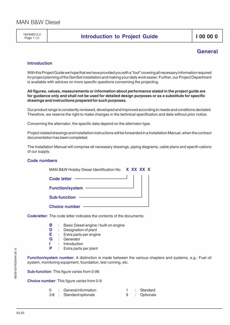
Code numbers
MAN B&W Holeby Diesel Identification No. X XX XX X
Code letter
Function/system
Sub-function
Choice number
Code letter: The code letter indicates the contents of the documents:
B : Basic Diesel engine / built-on engineD : Designation of plantE : Extra parts per engineG : GeneratorI : IntroductionP : Extra parts per plant
Function/system number: A distinction is made between the various chapters and systems, e.g.: Fuel oilsystem, monitoring equipment, foundation, test running, etc.
Sub-function: This figure varies from 0-99.
Choice number: This figure varies from 0-9:
0 : General information 1 : Standard2-8 : Standard optionals 9 : Optionals
03.20

0802
8-0D
/H52
50/9
4.08
.12
MAN B&W Diesel
Key for Engine Designation
General
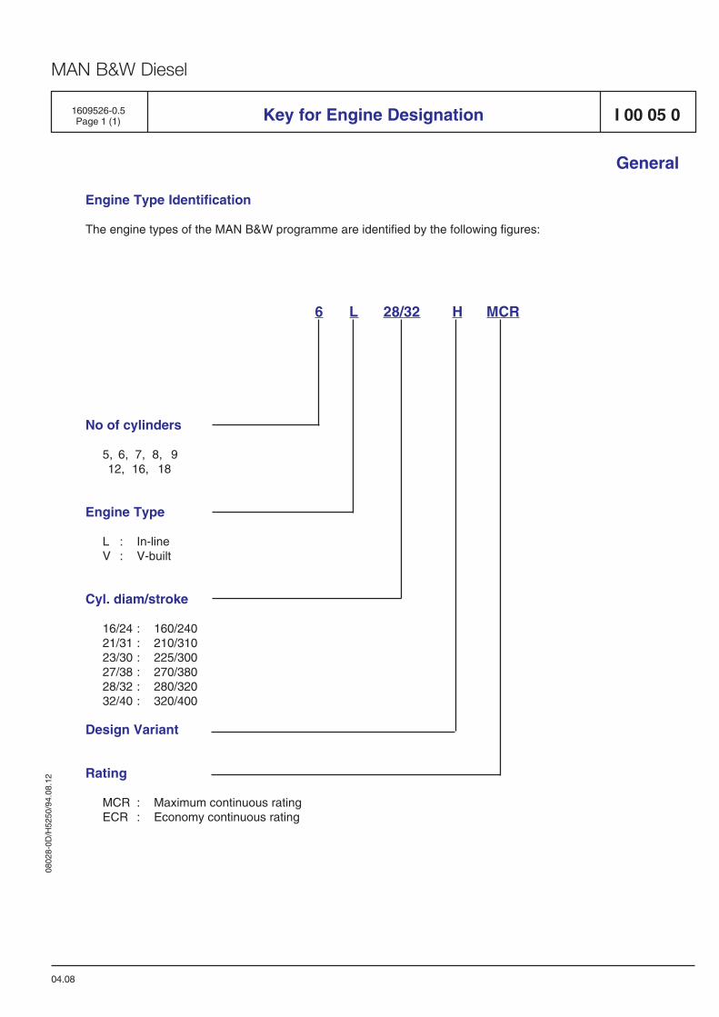
No of cylinders
5, 6, 7, 8, 912, 16, 18
Engine Type
L : In-lineV : V-built
Cyl. diam/stroke
16/24 : 160/24021/31 : 210/31023/30 : 225/30027/38 : 270/38028/32 : 280/32032/40 : 320/400
Design Variant
Rating
MCR : Maximum continuous ratingECR : Economy continuous rating
6 L 28/32 H MCR
04.08
1609526-0.5Page 1 (1)
Engine Type Identification
The engine types of the MAN B&W programme are identified by the following figures:
I 00 05 0

0802
8-0D
/H52
50/9
4.08
.12
MAN B&W Diesel
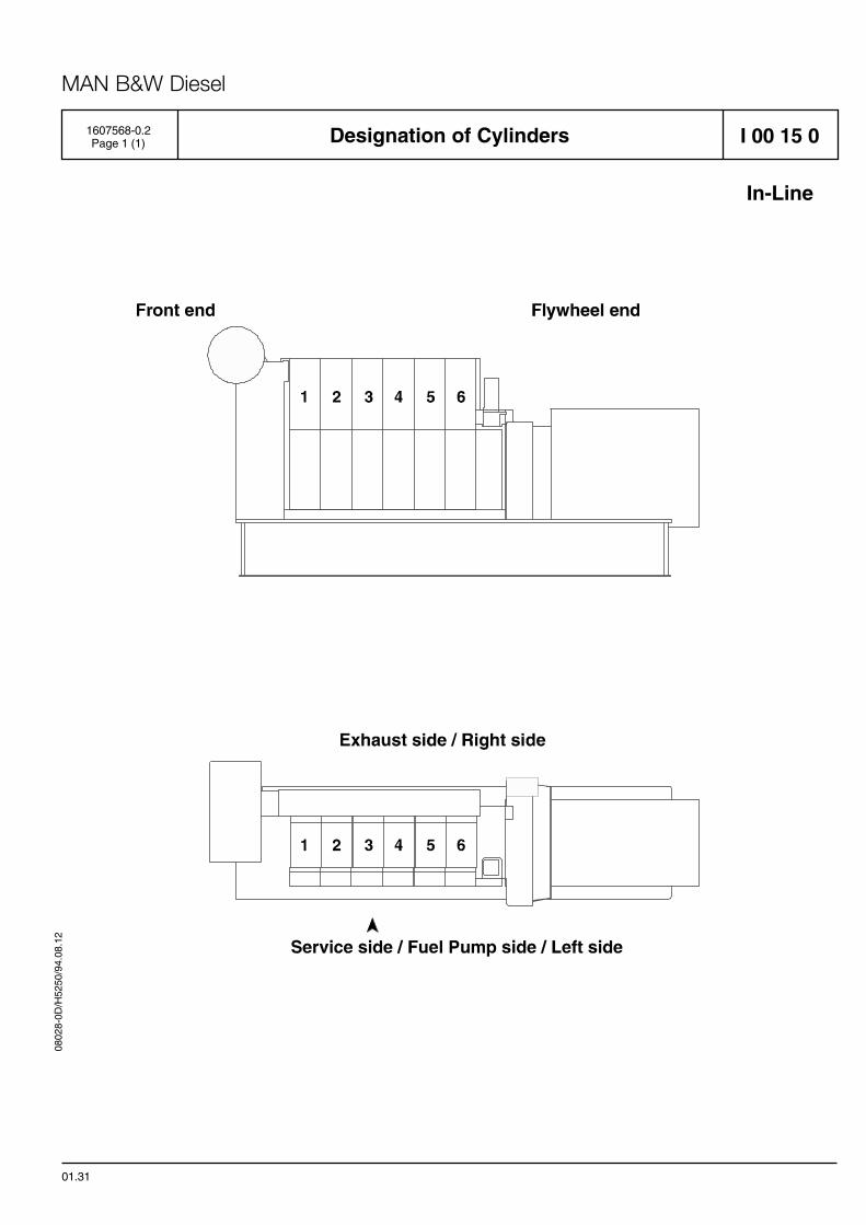
Designation of Cylinders
In-Line
01.31
1607568-0.2Page 1 (1) I 00 15 0

0802
8-0D
/H52
50/9
4.08
.12
MAN B&W Diesel
Code Identification for Instruments
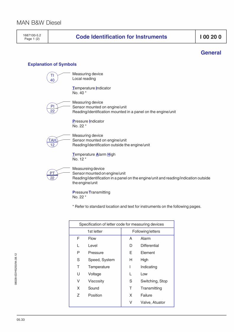
Explanation of Symbols
Measuring deviceLocal reading
Temperature IndicatorNo. 40 *
Measuring deviceSensor mounted on engine/unitReading/identification mounted in a panel on the engine/unit
Pressure IndicatorNo. 22 *
Measuring deviceSensor mounted on engine/unitReading/identification outside the engine/unit
Temperature Alarm HighNo. 12 *
Measureing deviceSensor mounted on engine/unitReading/identification in a panel on the engine/unit and reading/indication outsidethe engine/unit
Pressure TransmittingNo. 22 *
* Refer to standard location and text for instruments on the following pages.
Specification of letter code for measuring devices
1st letter Following letters
F Flow A Alarm
L Level D Differential
P Pressure E Element
S Speed, System H High
T Temperature I Indicating
U Voltage L Low
V Viscosity S Switching, Stop
X Sound T Transmitting
Z Position X Failure
V Valve, Atuator
05.33
TI40
TAH12
PI22
1687100-5.2Page 1 (2)
General
I 00 20 0
PT22
0802
8-0D
/H52
50/9
4.08
.12
MAN B&W Diesel
Code Identification for Instruments
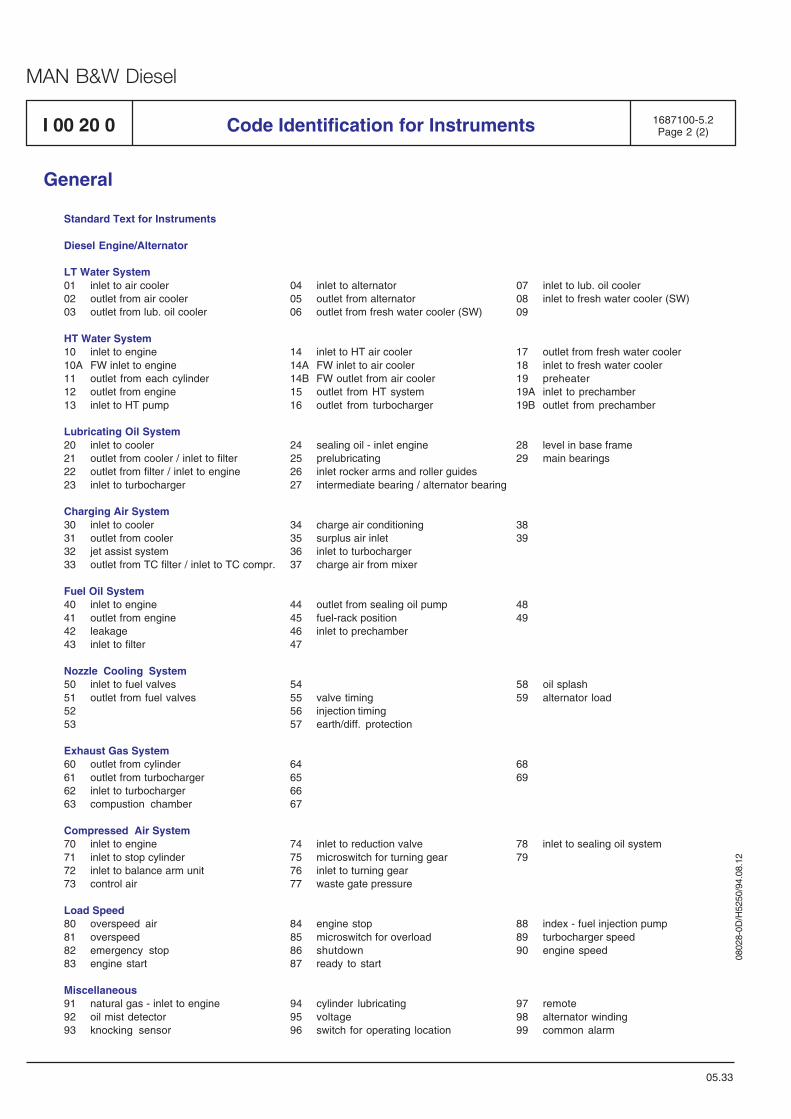
Standard Text for Instruments
Diesel Engine/Alternator
LT Water System01 inlet to air cooler 04 inlet to alternator 07 inlet to lub. oil cooler02 outlet from air cooler 05 outlet from alternator 08 inlet to fresh water cooler (SW)03 outlet from lub. oil cooler 06 outlet from fresh water cooler (SW) 09
HT Water System10 inlet to engine 14 inlet to HT air cooler 17 outlet from fresh water cooler10A FW inlet to engine 14A FW inlet to air cooler 18 inlet to fresh water cooler11 outlet from each cylinder 14B FW outlet from air cooler 19 preheater12 outlet from engine 15 outlet from HT system 19A inlet to prechamber13 inlet to HT pump 16 outlet from turbocharger 19B outlet from prechamber
Lubricating Oil System20 inlet to cooler 24 sealing oil - inlet engine 28 level in base frame21 outlet from cooler / inlet to filter 25 prelubricating 29 main bearings22 outlet from filter / inlet to engine 26 inlet rocker arms and roller guides23 inlet to turbocharger 27 intermediate bearing / alternator bearing
Charging Air System30 inlet to cooler 34 charge air conditioning 3831 outlet from cooler 35 surplus air inlet 3932 jet assist system 36 inlet to turbocharger33 outlet from TC filter / inlet to TC compr. 37 charge air from mixer
Fuel Oil System40 inlet to engine 44 outlet from sealing oil pump 4841 outlet from engine 45 fuel-rack position 4942 leakage 46 inlet to prechamber43 inlet to filter 47
Nozzle Cooling System50 inlet to fuel valves 54 58 oil splash51 outlet from fuel valves 55 valve timing 59 alternator load52 56 injection timing53 57 earth/diff. protection
Exhaust Gas System60 outlet from cylinder 64 6861 outlet from turbocharger 65 6962 inlet to turbocharger 6663 compustion chamber 67
Compressed Air System70 inlet to engine 74 inlet to reduction valve 78 inlet to sealing oil system71 inlet to stop cylinder 75 microswitch for turning gear 7972 inlet to balance arm unit 76 inlet to turning gear73 control air 77 waste gate pressure
Load Speed80 overspeed air 84 engine stop 88 index - fuel injection pump81 overspeed 85 microswitch for overload 89 turbocharger speed82 emergency stop 86 shutdown 90 engine speed83 engine start 87 ready to start
Miscellaneous91 natural gas - inlet to engine 94 cylinder lubricating 97 remote92 oil mist detector 95 voltage 98 alternator winding93 knocking sensor 96 switch for operating location 99 common alarm
05.33
1687100-5.2Page 2 (2)
General
I 00 20 0
0802
8-0D
\H52
50\9
4.08
.12
MAN B&W Diesel
1.1
1.2
1.3
1.4
1.5
1.6
1.7
1.8
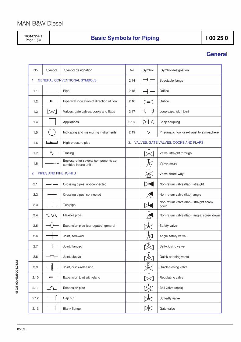
No Symbol Symbol designation
1. GENERAL CONVENTIONAL SYMBOLS
2. PIPES AND PIPE JOINTS
2.1
2.2
2.3
2.4
2.5
2.6
2.7
2.8
2.9
2.10
2.11
2.12
2.13
2.14
2.15
2.16
2.17
2.18.
2.19
No Symbol Symbol designation
3. VALVES, GATE VALVES, COCKS AND FLAPS
Pipe
Pipe with indication of direction of flow
Valves, gate valves, cocks and flaps
Appliances
Indicating and measuring instruments
High-pressure pipe
Tracing
Crossing pipes, not connected
Crossing pipes, connected
Tee pipe
Flexible pipe
Expansion pipe (corrugated) general
Joint, screwed
Joint, flanged
Joint, sleeve
Joint, quick-releasing
Expansion joint with gland
Expansion pipe
Cap nut
Blank flange
Spectacle flange
Orifice
Orifice
Loop expansion joint
Snap coupling
Pneumatic flow or exhaust to atmosphere
Valve, straight through
Valve, angle
Valve, three-way
Non-return valve (flap), straight
Non-return valve (flap), angle
Non-return valve (flap), angle, screw down
Safety valve
Angle safety valve
Self-closing valve
Quick-opening valve
Quick-closing valve
Regulating valve
Ball valve (cock)
Butterfly valve
Gate valve
Enclosure for several components as-sembled in one unit
Non-return valve (flap), straight screwdown
1631472-4.1Page 1 (3) Basic Symbols for Piping I 00 25 0
General
05.02
0802
8-0D
\H52
50\9
4.08
.12
MAN B&W Diesel
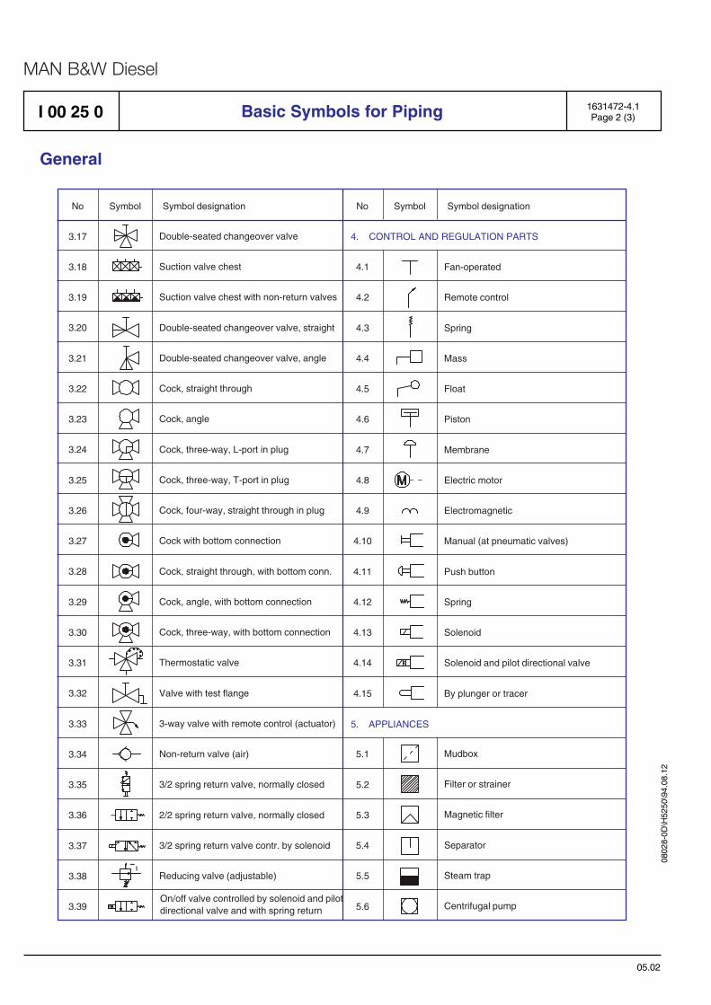
No Symbol Symbol designation No Symbol Symbol designation
3.17
3.18
3.19
3.20
3.21
3.22
3.23
3.24
3.25
3.26
3.27
3.28
3.29
3.30
3.31
3.32
3.33
3.34
3.35
3.36
3.37
3.38
3.39
Double-seated changeover valve
Suction valve chest
Suction valve chest with non-return valves
Double-seated changeover valve, straight
Double-seated changeover valve, angle
Cock, straight through
Cock, angle
Cock, three-way, L-port in plug
Cock, three-way, T-port in plug
Cock, four-way, straight through in plug
Cock with bottom connection
Cock, straight through, with bottom conn.
Cock, angle, with bottom connection
Cock, three-way, with bottom connection
Thermostatic valve
Valve with test flange
3-way valve with remote control (actuator)
Non-return valve (air)
3/2 spring return valve, normally closed
2/2 spring return valve, normally closed
3/2 spring return valve contr. by solenoid
Reducing valve (adjustable)
4. CONTROL AND REGULATION PARTS
Fan-operated
Remote control
Spring
Mass
Float
Piston
Membrane
Electric motor
Electromagnetic
Manual (at pneumatic valves)
Push button
Spring
Solenoid
Solenoid and pilot directional valve
By plunger or tracer
4.1
4.2
4.3
4.4
4.5
4.6
4.7
4.8
4.9
4.10
4.11
4.12
4.13
4.14
4.15
5. APPLIANCES
5.1
5.2
5.3
5.4
5.5
5.6
Mudbox
Filter or strainer
Magnetic filter
Separator
Steam trap
Centrifugal pumpOn/off valve controlled by solenoid and pilotdirectional valve and with spring return
I 00 25 0 1631472-4.1Page 2 (3)Basic Symbols for Piping
General
05.02
0802
8-0D
\H52
50\9
4.08
.12
MAN B&W Diesel
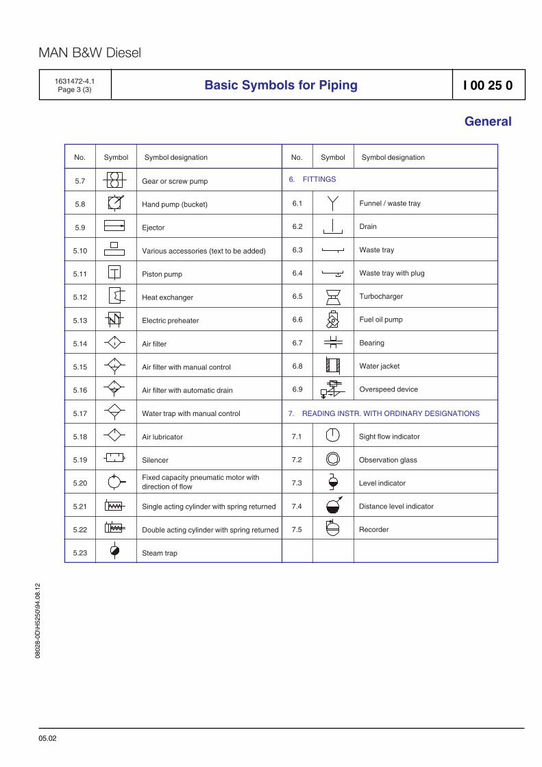
No. Symbol Symbol designation No. Symbol Symbol designation
5.7
5.8
5.9
5.10
5.11
5.12
5.13
5.14
5.15
5.16
5.17
5.18
5.19
5.20
5.21
5.22
5.23
Gear or screw pump
Hand pump (bucket)
Ejector
Various accessories (text to be added)
Piston pump
Heat exchanger
Electric preheater
Air filter
Air filter with manual control
Air filter with automatic drain
Water trap with manual control
Air lubricator
Silencer
Single acting cylinder with spring returned
Double acting cylinder with spring returned
Steam trap
7. READING INSTR. WITH ORDINARY DESIGNATIONS
7.1
7.2
7.3
7.4
7.5
Sight flow indicator
Observation glass
Level indicator
Distance level indicator
Recorder
6. FITTINGS
6.1
6.2
6.3
6.4
6.5
6.6
6.7
6.8
6.9
Funnel / waste tray
Drain
Waste tray
Waste tray with plug
Turbocharger
Fuel oil pump
Bearing
Water jacket
Overspeed device
Fixed capacity pneumatic motor withdirection of flow
1631472-4.1Page 3 (3) Basic Symbols for Piping I 00 25 0
General
05.02


General information
D 10

0802
8-0D
/H52
50/9
4.08
.12
MAN B&W Diesel
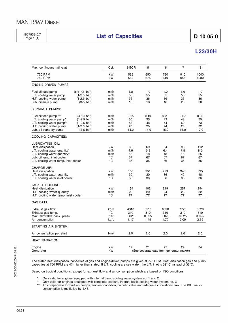
1607532-0.7Page 1 (1) List of Capacities D 10 05 0
L23/30H
00.33
Max. continuous rating at Cyl. 5-ECR 5 6 7 8
720 RPM kW 525 650 780 910 1040750 RPM kW 550 675 810 945 1080
ENGINE-DRIVEN PUMPS.
Fuel oil feed pump (5.5-7.5 bar) m3/h 1.0 1.0 1.0 1.0 1.0L.T. cooling water pump (1-2.5 bar) m3/h 55 55 55 55 55H.T. cooling water pump (1-2.5 bar) m3/h 36 36 36 36 36Lub. oil main pump (3-5 bar) m3/h 16 16 16 20 20
SEPARATE PUMPS:
Fuel oil feed pump *** (4-10 bar) m3/h 0.15 0.19 0.23 0.27 0.30L.T. cooling water pump* (1-2.5 bar) m3/h 35 35 42 48 55L.T. cooling water pump** (1-2.5 bar) m3/h 48 48 54 60 73H.T. cooling water pump (1-2.5 bar) m3/h 20 20 24 28 32Lub. oil stand-by pump (3-5 bar) m3/h 14.0 14.0 15.0 16.0 17.0
COOLING CAPACITIES:
LUBRICATING OIL:Heat dissipation kW 63 69 84 98 112L.T. cooling water quantity* m3/h 4.6 5.3 6.4 7.5 8.5L.T. cooling water quantity** m3/h 18 18 18 18 25Lub. oil temp. inlet cooler °C 67 67 67 67 67L.T. cooling water temp. inlet cooler °C 36 36 36 36 36
CHARGE AIR:Heat dissipation kW 156 251 299 348 395L.T. cooling water quantity m3/h 30 30 36 42 48L.T. cooling water inlet cooler °C 36 36 36 36 36
JACKET COOLING:Heat dissipation kW 154 182 219 257 294H.T. cooling water quantity m3/h 20 20 24 28 32H.T. cooling water temp. inlet cooler °C 77 77 77 77 77
GAS DATA:
Exhaust gas flow kg/h 4310 5510 6620 7720 8820Exhaust gas temp. °C 310 310 310 310 310Max. allowable back. press. bar 0.025 0.025 0.025 0.025 0.025Air consumption kg/s 1.17 1.49 1.79 2.09 2.39
STARTING AIR SYSTEM:
Air consumption per start Nm3 2.0 2.0 2.0 2.0 2.0
HEAT RADIATION:
Engine kW 19 21 25 29 34Generator kW (See separate data from generator maker)
The stated heat dissipation, capacities of gas and engine-driven pumps are given at 720 RPM. Heat dissipation gas and pumpcapacities at 750 RPM are 4% higher than stated. If L.T. cooling are sea water, the L.T. inlet is 32° C instead of 36°C.
Based on tropical conditions, except for exhaust flow and air consumption which are based on ISO conditions.
* Only valid for engines equipped with internal basic cooling water system no. 1 and 2.** Only valid for engines equipped with combined coolers, internal basic cooling water system no. 3.*** To compensate for built on pumps, ambient condition, calorific value and adequate circulations flow. The ISO fuel oil
consumption is multiplied by 1.45.

0802
8-0D
/H52
50/9
4.08
.12
MAN B&W Diesel
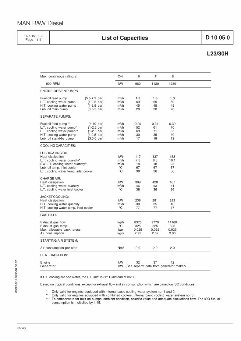
Max. continuous rating at Cyl. 6 7 8
900 RPM kW 960 1120 1280
ENGINE-DRIVEN PUMPS.
Fuel oil feed pump (5.5-7.5 bar) m3/h 1.3 1.3 1.3L.T. cooling water pump (1-2.5 bar) m3/h 69 69 69H.T. cooling water pump (1-2.5 bar) m3/h 45 45 45Lub. oil main pump (3.5-5 bar) m3/h 20 20 20
SEPARATE PUMPS:
Fuel oil feed pump *** (4-10 bar) m3/h 0.29 0.34 0.39L.T. cooling water pump* (1-2.5 bar) m3/h 52 61 70L.T. cooling water pump** (1-2.5 bar) m3/h 63 71 85H.T. cooling water pump (1-2.5 bar) m3/h 30 35 40Lub. oil stand-by pump (3.5-5 bar) m3/h 17 18 19
COOLING CAPACITIES:
LUBRICATING OIL:Heat dissipation kW 117 137 158L.T. cooling water quantity* m3/h 7.5 8.8 10.1SW L.T. cooling water quantity** m3/h 18 18 25Lub. oil temp. inlet cooler °C 67 67 67L.T. cooling water temp. inlet cooler °C 36 36 36
CHARGE AIR:Heat dissipation kW 369 428 487L.T. cooling water quantity m3/h 46 53 61L.T. cooling water inlet cooler °C 36 36 36
JACKET COOLING:Heat dissipation kW 239 281 323H.T. cooling water quantity m3/h 30 35 40H.T. cooling water temp. inlet cooler °C 77 77 77
GAS DATA:
Exhaust gas flow kg/h 8370 9770 11160Exhaust gas temp. °C 325 325 325Max. allowable back. press. bar 0.025 0.025 0.025Air consumption kg/s 2.25 2.62 3.00
STARTING AIR SYSTEM:
Air consumption per start Nm3 2.0 2.0 2.0
HEAT RADIATION:
Engine kW 32 37 42Generator kW (See separat data from generator maker)
If L.T. cooling are sea water, the L.T. inlet is 32° C instead of 36° C.
Based on tropical conditions, except for exhaust flow and air consumption which are based on ISO conditions.
* Only valid for engines equipped with internal basic cooling water system no. 1 and 2.** Only valid for engines equipped with combined coolers, internal basic cooling water system no. 3.*** To compensate for built on pumps, ambient condition, calorific value and adequate circulations flow. The ISO fuel oil
consumption is multiplied by 1.45.
1699151-1.0Page 1 (1) List of Capacities D 10 05 0
05.48
L23/30H

0802
8-0D
/H52
50/9
4.08
.12
MAN B&W Diesel
Smoke-Bosch(1 stroke)
RB
Spec. fuel cons.g/kWh*
max. pressurecompr.pressure
bar
Exhaust temp.grC
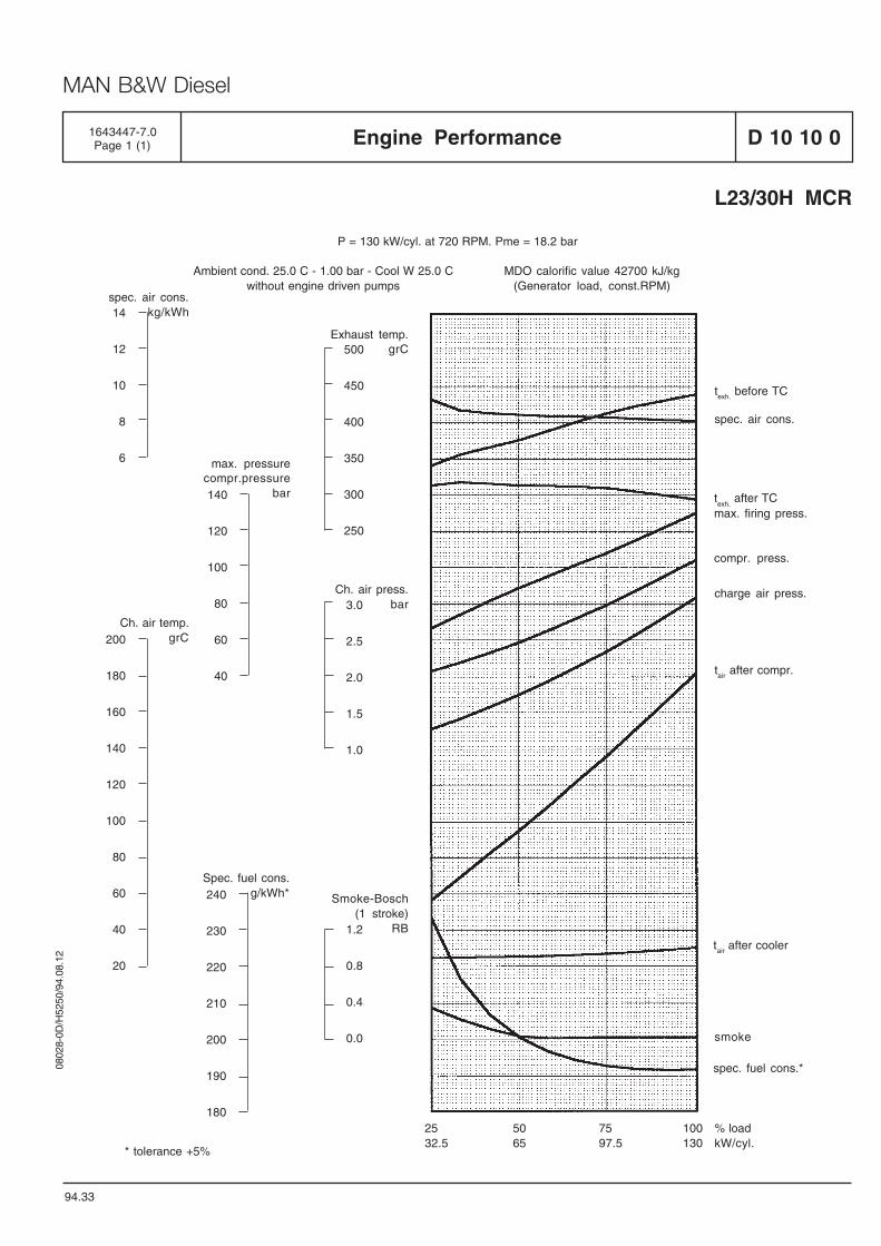
D 10 10 0Engine Performance1643447-7.0Page 1 (1)
94.33
25 50 75 100 % load32.5 65 97.5 130 kW/cyl.
* tolerance +5%
spec. air cons.
smoke
1.2
0.8
0.4
0.0
3.0
2.5
2.0
1.5
1.0
500
450
400
350
300
250
P = 130 kW/cyl. at 720 RPM. Pme = 18.2 bar
Ambient cond. 25.0 C - 1.00 bar - Cool W 25.0 C MDO calorific value 42700 kJ/kgwithout engine driven pumps (Generator load, const.RPM)
14
12
10
8
6
spec. air cons.kg/kWh
200
180
160
140
120
100
80
60
40
20
Ch. air temp.grC
140
120
100
80
60
40
240
230
220
210
200
190
180
L23/30H MCR
Ch. air press.bar
spec. fuel cons.*
tair after cooler
charge air press.
tair after compr.
compr. press.
max. firing press.texh.
after TC
texh. before TC

0802
8-0D
/H52
50/9
4.08
.12
MAN B&W Diesel
Smoke-Bosch(1 stroke)
RB
Spec. fuel cons.g/kWh*
max. pressurecompr.pressure
bar
Exhaust temp.grC
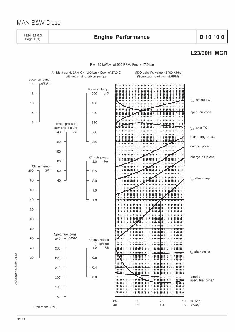
D 10 10 0Engine Performance1624432-9.3Page 1 (1)
92.41
25 50 75 100 % load40 80 120 160 kW/cyl.
* tolerance +5%
texh. before TC
spec. air cons.
texh. after TC
max. firing press.
compr. press.
charge air press.
tair after compr.
tair after cooler
smokespec. fuel cons.*
1.2
0.8
0.4
0.0
3.0
2.5
2.0
1.5
1.0
500
450
400
350
300
250
P = 160 kW/cyl. at 900 RPM. Pme = 17.9 bar
Ambient cond. 27.0 C - 1.00 bar - Cool W 27.0 C MDO calorific value 42700 kJ/kgwithout engine driven pumps (Generator load, const.RPM)
14
12
10
8
6
spec. air cons.kg/kWh
200
180
160
140
120
100
80
60
40
20
Ch. air temp.grC
140
120
100
80
60
40
240
230
220
210
200
190
180
L23/30H MCR
Ch. air press.bar

0802
8-0D
/H52
50/9
4.08
.12
MAN B&W Diesel
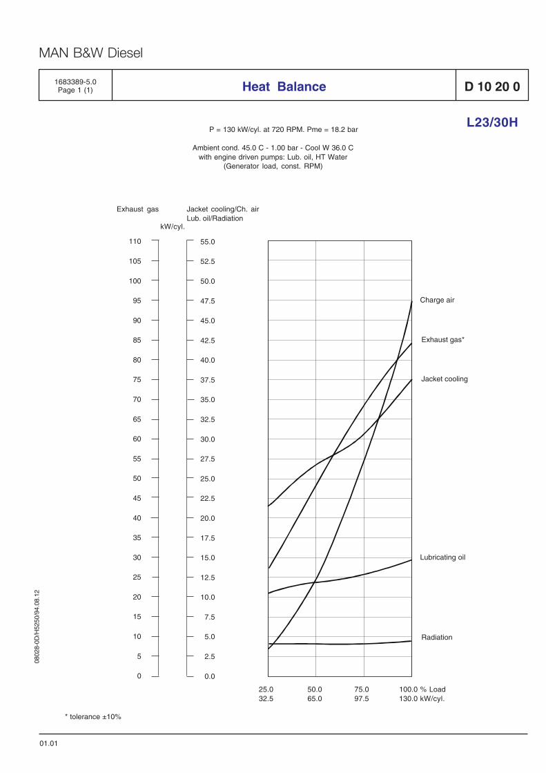
D 10 20 01683389-5.0Page 1 (1) Heat Balance
L23/30H
01.01
* tolerance ±10%
P = 130 kW/cyl. at 720 RPM. Pme = 18.2 bar
Ambient cond. 45.0 C - 1.00 bar - Cool W 36.0 Cwith engine driven pumps: Lub. oil, HT Water
(Generator load, const. RPM)
25.0 50.0 75.0 100.0 % Load32.5 65.0 97.5 130.0 kW/cyl.
Charge air
Exhaust gas*
Jacket cooling
Radiation
Lubricating oil
Jacket cooling/Ch. airLub. oil/Radiation
Exhaust gas
kW/cyl.
110
105
100
95
90
85
80
75
70
65
60
55
50
45
40
35
30
25
20
15
10
5
0
55.0
52.5
50.0
47.5
45.0
42.5
40.0
37.5
35.0
32.5
30.0
27.5
25.0
22.5
20.0
17.5
15.0
12.5
10.0
7.5
5.0
2.5
0.0

0802
8-0D
/H52
50/9
4.08
.12
MAN B&W Diesel
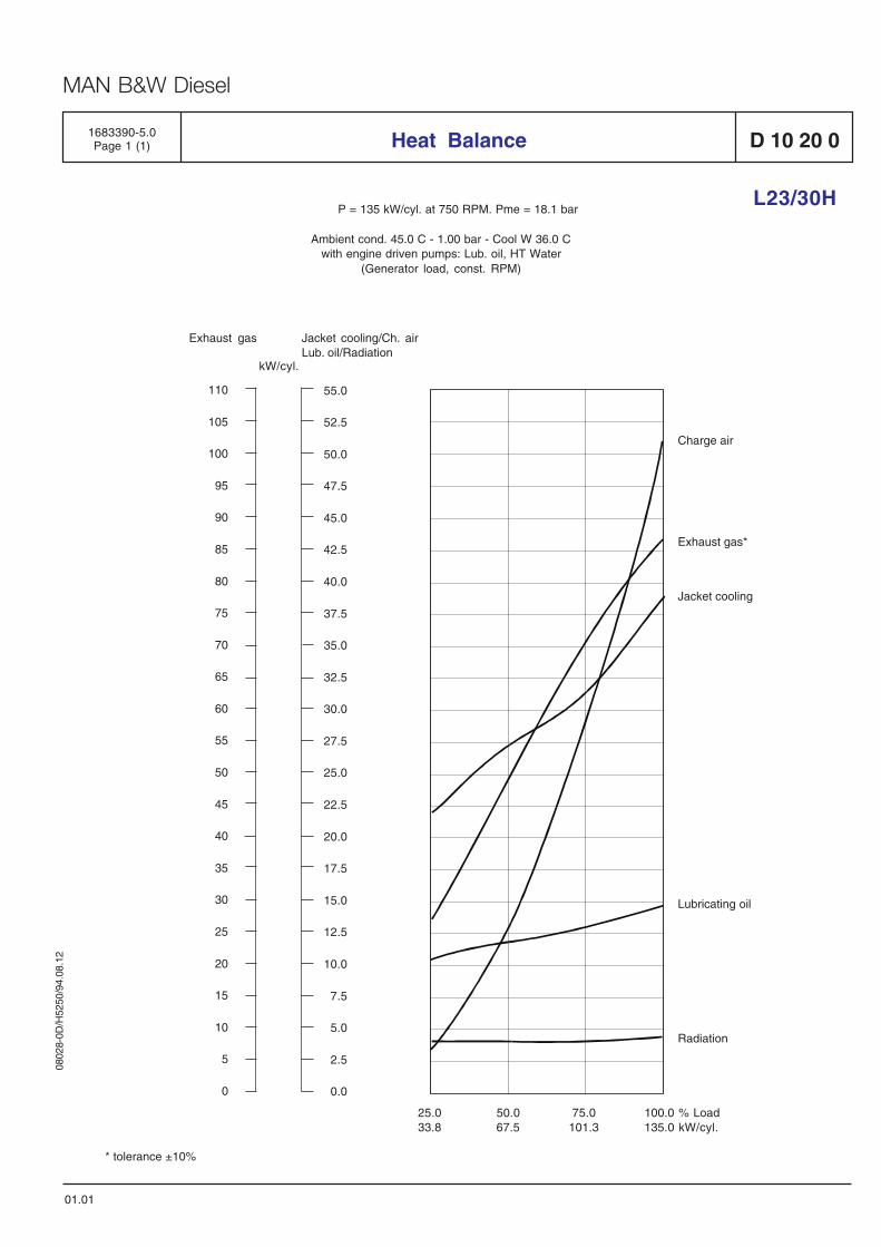
D 10 20 01683390-5.0Page 1 (1) Heat Balance
L23/30H
01.01
* tolerance ±10%
P = 135 kW/cyl. at 750 RPM. Pme = 18.1 bar
Ambient cond. 45.0 C - 1.00 bar - Cool W 36.0 Cwith engine driven pumps: Lub. oil, HT Water
(Generator load, const. RPM)
25.0 50.0 75.0 100.0 % Load33.8 67.5 101.3 135.0 kW/cyl.
Charge air
Exhaust gas*
Jacket cooling
Radiation
Lubricating oil
Jacket cooling/Ch. airLub. oil/Radiation
Exhaust gas
kW/cyl.
110
105
100
95
90
85
80
75
70
65
60
55
50
45
40
35
30
25
20
15
10
5
0
55.0
52.5
50.0
47.5
45.0
42.5
40.0
37.5
35.0
32.5
30.0
27.5
25.0
22.5
20.0
17.5
15.0
12.5
10.0
7.5
5.0
2.5
0.0

0802
8-0D
/H52
50/9
4.08
.12
MAN B&W Diesel
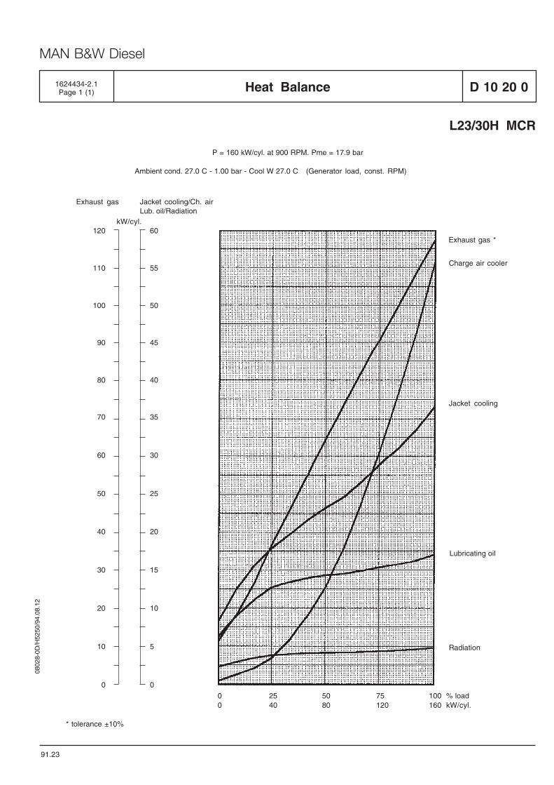
D 10 20 0
91.23
Heat Balance1624434-2.1Page 1 (1)
P = 160 kW/cyl. at 900 RPM. Pme = 17.9 bar
Ambient cond. 27.0 C - 1.00 bar - Cool W 27.0 C (Generator load, const. RPM)
* tolerance ±10%
Jacket cooling/Ch. airLub. oil/Radiation
Exhaust gas
kW/cyl.
0 25 50 75 100 % load0 40 80 120 160 kW/cyl.
Radiation
Lubricating oil
Jacket cooling
Exhaust gas *
Charge air cooler
120
110
100
90
80
60
55
50
45
40
70
60
50
40
30
20
10
0
35
30
25
20
15
10
5
0
L23/30H MCR

0802
8-0D
/H52
50/9
4.08
.12
MAN B&W Diesel
Measuring of unsilenced exhaust sound is carriedout at the test bed, directly after turbocharger, with aprobe microphone inside the exhaust pipe.
Sound Measuring "on-site"
The Sound Power Level can be directly applied toon-site conditions. It does not, however, necessarilyresult in the same Sound Pressure Level as measuredon test bed.
Normally the Sound Pressure Level on-site is 3-5 dBhigher than the given surface Sound Pressure Level(Lpf) measured at test bed. However, it dependsstrongly on the acoustical properties of the actualengine room.
Small rooms with hard non-absorbing walls giveseven higher values, while large rooms withhigh-absorbing walls only result in minor deviations.
The actual Sound Pressure Level measured on-site,also depends on the number of sound sources, andhow these are placed.
Standards
Determination of Sound Power from Sound Pressuremeasurements will normally be carried outaccording to:
ISO 3744 (Measuring method, instruments,background noise, no of microphone positions etc)andISO 3746 (Accuracy due to criterion for suitability oftest environment, K2>2 dB)
Measurement of unsilenced exhaust sound is asmentioned previously carried out with a probe micro-phone inside the exhaust pipe, directly after theturbocharger.
Even no present standard is accessible for this typeof measurement, we consider this method for givingthe most reliable result.
Purpose
This should be seen as an easily comprehensiblesound analysis of MAN B&W Diesel GenSets. Thesemeasurements can be used in the project phase asa basis for decisions concerning damping andisolation in buildings, engine rooms and aroundexhaust systems.
Measuring Equipment
All measurements have been made with PrecisionSound Level Meters according to standard IECPublication 651or 804, type 1 - with 1/1 or 1/3 octavefilters according to standard IEC Publication 225.Used sound calibrators are according to standardIEC Publication 942, class 1.
Definitions
Sound Pressure Level: LP = 20 x log P/P
0 [dB]
where P is the RMS value of sound pressure inpascals, and P
0 is 20 µPa for measurement in air.
Sound Power Level: LW = 10 x log P/P
0 [dB]
where P is the RMS value of sound power in watts,and P
0 is 1 pW.
Measuring Conditions
All measurements are carried out in one of MANB&W Diesel's test bed facilities.
During measurements, the exhaust gas is led outsidethe test bed through a silencer. The GenSet is placedon a resilient bed with generator and engine on acommon base frame.
Sound Power are normally determined from SoundPressure measurements.
06.02
General
D 10 25 0Description of Sound Measurements1609510-3.4Page 1 (1)

0802
8-0D
/H52
50/9
4.08
.12
MAN B&W Diesel
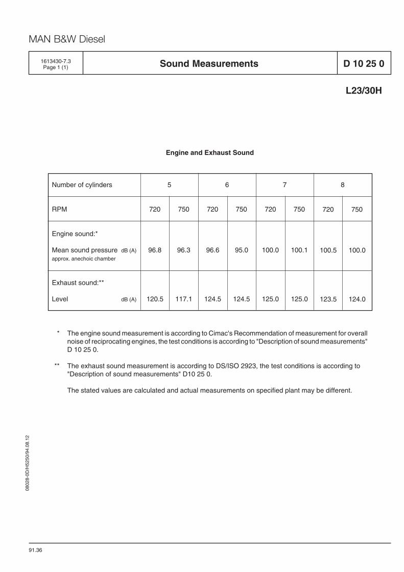
1613430-7.3Page 1 (1) Sound Measurements D 10 25 0
L23/30H
Number of cylinders
RPM
Engine sound:*
Mean sound pressure dB (A)
approx. anechoic chamber
Exhaust sound:**
Level dB (A)
5 6 7 8
720
96.8
120.5
750
96.3
117.1
720
96.6
124.5
750
95.0
124.5
720
100.0
125.0
750
100.1
125.0
720
100.5
123.5
750
100.0
124.0
Engine and Exhaust Sound
* The engine sound measurement is according to Cimac's Recommendation of measurement for overallnoise of reciprocating engines, the test conditions is according to "Description of sound measurements"D 10 25 0.
** The exhaust sound measurement is according to DS/ISO 2923, the test conditions is according to"Description of sound measurements" D10 25 0.
The stated values are calculated and actual measurements on specified plant may be different.
91.36

0802
8-0D
/H52
50/9
4.08
.12
MAN B&W Diesel
General
99.34
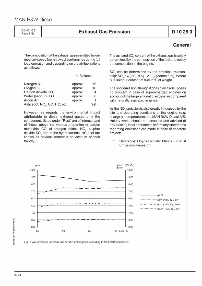
The composition of the exhaust gases emitted by ourmedium-speed four-stroke diesel engines during fullload operation and depending on the air/fuel ratio isas follows:
% Volume
Nitrogen N2
approx. 76Oxygen O
2approx. 13
Carbon dioxide CO2
approx. 4Water (vapour) H
2O approx. 6
Argon Ar approx. 1Ash, soot, NO
x, CO, HC, etc. rest
However, as regards the environmental impactattributable to diesel exhaust gases only thecomponents listed under "Rest" are of interest, andof these, above the various proportion of carbonmonoxide, CO, of nitrogen oxides, NO
x, sulphur
dioxide SO2 and of the hydrocarbons, HC, that are
known as noxious materials on account of theirtoxicity.
D 10 28 0Exhaust Gas Emission1624461-6.2Page 1 (1)
The ash and SO2 content of the exhaust gas is solely
determined by the composition of the fuel and not bythe combustion in the engine.
SO2 can be determined by the empirical relation-
ship: SO2 * = (21.9 x S) - 2.1 (kg/tonne fuel). Where
S is sulphur content of fuel in % of weight.
The soot emission, though it does play a role, posesno problem in case of super-charged engines onaccount of the large amount of excess air comparedwith naturally aspirated engines.
As the NOx emission is also greatly influenced by the
site and operating conditions of the engine (e.g.charge air temperature), the MAN B&W Diesel A/S,Holeby works should be consulted and advised ofany existing local ordinances before any statementsregarding emissions are made in case of concreteprojects.
* Reference: Lloyds Register Marine ExhaustEmissions Research.
g/Nm (5% O ),g/kWh
200
300
400
500
600
700
800
900
1000
ppm
25 50 75 100 Load %
2.00
3.00
4.00
5.00
6.00
7.00
8.00
9.00
10.00
32
g/kWh
ppm (15% O , wet)
g/Nm (5% O , dry)
ppm (13% O , dry)
32
2
2
Fig. 1. Nox emission L23/30H and L/V28/32H engines according to ISO 3046 conditions.

0802
8-0D
/H52
50/9
4.08
.12
MAN B&W Diesel
1687135-3.0Page 1 (1) NOx Emission D 10 28 0
L23/30H
02.12
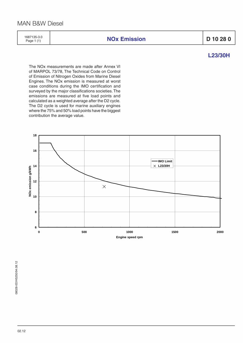
The NOx measurements are made after Annex VIof MARPOL 73/78, The Technical Code on Controlof Emission of Nitrogen Oxides from Marine DieselEngines. The NOx emission is measured at worstcase conditions during the IMO certification andsurveyed by the major classifications societies. Theemissions are measured at five load points andcalculated as a weighted average after the D2 cycle.The D2 cycle is used for marine auxiliary engineswhere the 75% and 50% load points have the biggestcontribution the average value.
6
8
10
12
14
16
18
0 500 1000 1500 2000Engine speed rpm
NO
x em
issi
on g
/kW
h
IMO LimitL23/30H

0802
8-0D
/H52
50/9
4.08
.12
MAN B&W Diesel
05.48
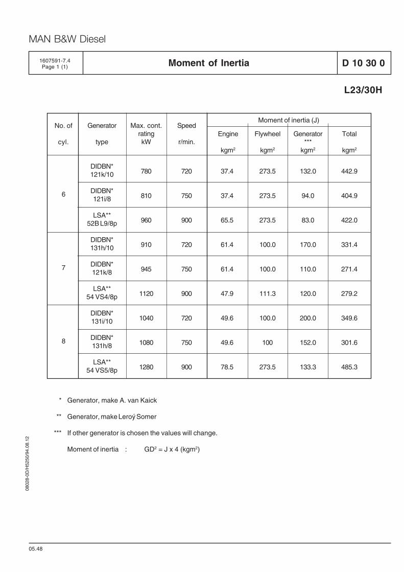
D 10 30 01607591-7.4Page 1 (1) Moment of Inertia
L23/30H
Moment of inertia (J)
Engine
kgm2
Flywheel
kgm2
Generator***
kgm2
Total
kgm2
780
810
960
910
945
1120
1040
1080
1280
720
750
900
720
750
900
720
750
900
37.4
37.4
65.5
61.4
61.4
47.9
49.6
49.6
78.5
273.5
273.5
273.5
100.0
100.0
111.3
100.0
100
273.5
132.0
94.0
83.0
170.0
110.0
120.0
200.0
152.0
133.3
442.9
404.9
422.0
331.4
271.4
279.2
349.6
301.6
485.3
Speed
r/min.
Max. cont.ratingkW
Generator
type
DIDBN*121k/10
DIDBN*121i/8
LSA**52B L9/8p
DIDBN*131h/10
DIDBN*121k/8
LSA**54 VS4/8p
DIDBN*131i/10
DIDBN*131h/8
LSA**54 VS5/8p
No. of
cyl.
6
7
8
* Generator, make A. van Kaick
** Generator, make Leroý Somer
*** If other generator is chosen the values will change.
Moment of inertia : GD2 = J x 4 (kgm2)

0802
8-0D
/H52
50/9
4.08
.12
MAN B&W Diesel
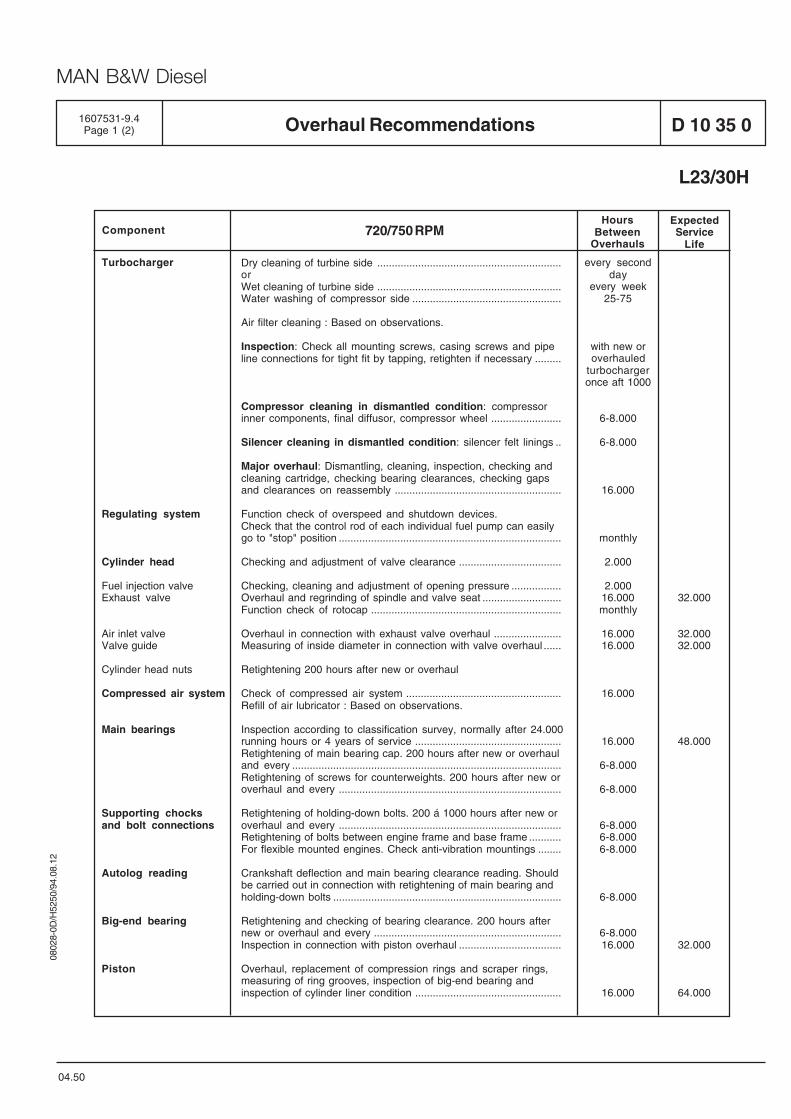
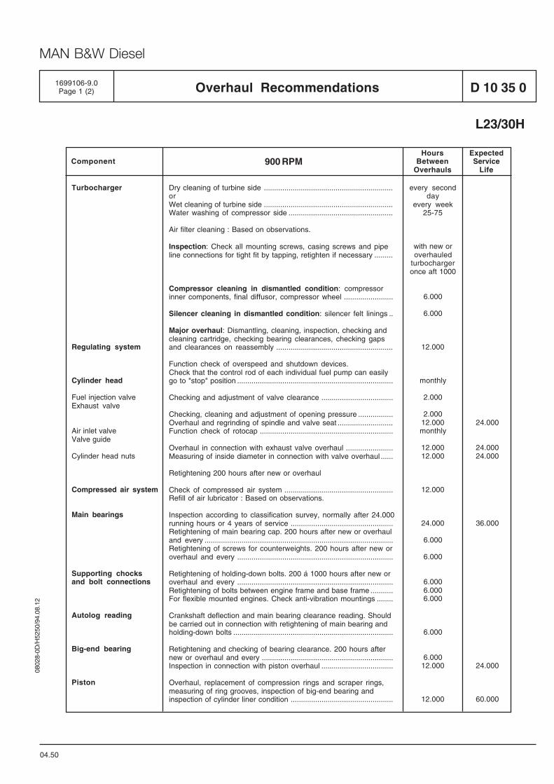
Overhaul Recommendations
04.50
D 10 35 01607531-9.4Page 1 (2)
Turbocharger
Regulating system
Cylinder head
Fuel injection valveExhaust valve
Air inlet valveValve guide
Cylinder head nuts
Compressed air system
Main bearings
Supporting chocksand bolt connections
Autolog reading
Big-end bearing
Piston
every secondday
every week25-75
with new oroverhauled
turbochargeronce aft 1000
6-8.000
6-8.000
16.000
monthly
2.000
2.00016.000monthly
16.00016.000
16.000
16.000
6-8.000
6-8.000
6-8.0006-8.0006-8.000
6-8.000
6-8.00016.000
16.000
32.000
32.00032.000
48.000
32.000
64.000
Dry cleaning of turbine side ...............................................................orWet cleaning of turbine side ...............................................................Water washing of compressor side ...................................................
Air filter cleaning : Based on observations.
Inspection: Check all mounting screws, casing screws and pipeline connections for tight fit by tapping, retighten if necessary .........
Compressor cleaning in dismantled condition: compressorinner components, final diffusor, compressor wheel ........................
Silencer cleaning in dismantled condition: silencer felt linings ..
Major overhaul: Dismantling, cleaning, inspection, checking andcleaning cartridge, checking bearing clearances, checking gapsand clearances on reassembly .........................................................
Function check of overspeed and shutdown devices.Check that the control rod of each individual fuel pump can easilygo to "stop" position ............................................................................
Checking and adjustment of valve clearance ...................................
Checking, cleaning and adjustment of opening pressure .................Overhaul and regrinding of spindle and valve seat ...........................Function check of rotocap .................................................................
Overhaul in connection with exhaust valve overhaul .......................Measuring of inside diameter in connection with valve overhaul ......
Retightening 200 hours after new or overhaul
Check of compressed air system .....................................................Refill of air lubricator : Based on observations.
Inspection according to classification survey, normally after 24.000running hours or 4 years of service ..................................................Retightening of main bearing cap. 200 hours after new or overhauland every ............................................................................................Retightening of screws for counterweights. 200 hours after new oroverhaul and every ............................................................................
Retightening of holding-down bolts. 200 á 1000 hours after new oroverhaul and every ............................................................................Retightening of bolts between engine frame and base frame ...........For flexible mounted engines. Check anti-vibration mountings ........
Crankshaft deflection and main bearing clearance reading. Shouldbe carried out in connection with retightening of main bearing andholding-down bolts ..............................................................................
Retightening and checking of bearing clearance. 200 hours afternew or overhaul and every ................................................................Inspection in connection with piston overhaul ...................................
Overhaul, replacement of compression rings and scraper rings,measuring of ring grooves, inspection of big-end bearing andinspection of cylinder liner condition ..................................................
L23/30H
ExpectedService
LifeComponent
HoursBetween
Overhauls720/750 RPM

0802
8-0D
/H52
50/9
4.08
.12
MAN B&W Diesel
D 10 35 0
04.50
1607531-9.4Page 2 (2)Overhaul Recommendations
L23/30H
ExpectedService
LifeComponent
HoursBetween
Overhauls720/750 RPM
Cylinder liner
Fuel pump
Torsional vibrationdampers
Lub. oil filter cartr.
Filter Cartridges
Inspection, measuring and reconditioning of running surfacecondition: In connection with piston overhaul ....................................
Overhaul and reconditioning of surface between liner and frame andcleaning of surface in cooling water space .......................................
Fuel pump barrel/plunger assembly. Overhaul based on operationalobservations .......................................................................................
Overhaul .............................................................................................A sample of silicone fluid must be taken and analysed in between.
Replacement based on observations of pressure drop ...................
Replacement based on observations ................................................
16.000
32.000
32.000
80.000
32.000
1.500
1.500
0802
8-0D
/H52
50/9
4.08
.12
MAN B&W Diesel
Turbocharger
Regulating system
Cylinder head
Fuel injection valveExhaust valve
Air inlet valveValve guide
Cylinder head nuts
Compressed air system
Main bearings
Supporting chocksand bolt connections
Autolog reading
Big-end bearing
Piston
every secondday
every week25-75
with new oroverhauled
turbochargeronce aft 1000
6.000
6.000
12.000
monthly
2.000
2.00012.000monthly
12.00012.000
12.000
24.000
6.000
6.000
6.0006.0006.000
6.000
6.00012.000
12.000
24.000
24.00024.000
36.000
24.000
60.000
Dry cleaning of turbine side ...............................................................orWet cleaning of turbine side ...............................................................Water washing of compressor side ...................................................
Air filter cleaning : Based on observations.
Inspection: Check all mounting screws, casing screws and pipeline connections for tight fit by tapping, retighten if necessary .........
Compressor cleaning in dismantled condition: compressorinner components, final diffusor, compressor wheel ........................
Silencer cleaning in dismantled condition: silencer felt linings ..
Major overhaul: Dismantling, cleaning, inspection, checking andcleaning cartridge, checking bearing clearances, checking gapsand clearances on reassembly .........................................................
Function check of overspeed and shutdown devices.Check that the control rod of each individual fuel pump can easilygo to "stop" position ............................................................................
Checking and adjustment of valve clearance ...................................
Checking, cleaning and adjustment of opening pressure .................Overhaul and regrinding of spindle and valve seat ...........................Function check of rotocap .................................................................
Overhaul in connection with exhaust valve overhaul .......................Measuring of inside diameter in connection with valve overhaul ......
Retightening 200 hours after new or overhaul
Check of compressed air system .....................................................Refill of air lubricator : Based on observations.
Inspection according to classification survey, normally after 24.000running hours or 4 years of service ..................................................Retightening of main bearing cap. 200 hours after new or overhauland every ............................................................................................Retightening of screws for counterweights. 200 hours after new oroverhaul and every ............................................................................
Retightening of holding-down bolts. 200 á 1000 hours after new oroverhaul and every ............................................................................Retightening of bolts between engine frame and base frame ...........For flexible mounted engines. Check anti-vibration mountings ........
Crankshaft deflection and main bearing clearance reading. Shouldbe carried out in connection with retightening of main bearing andholding-down bolts ..............................................................................
Retightening and checking of bearing clearance. 200 hours afternew or overhaul and every ................................................................Inspection in connection with piston overhaul ...................................
Overhaul, replacement of compression rings and scraper rings,measuring of ring grooves, inspection of big-end bearing andinspection of cylinder liner condition ..................................................
ExpectedService
LifeComponent
HoursBetween
Overhauls900 RPM
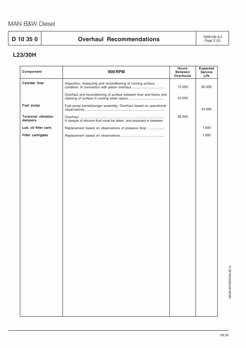
Overhaul Recommendations
04.50
D 10 35 01699106-9.0Page 1 (2)
L23/30H
0802
8-0D
/H52
50/9
4.08
.12
MAN B&W Diesel
D 10 35 0
04.50
1699106-9.0Page 2 (2)Overhaul Recommendations
L23/30H
ExpectedService
LifeComponent
HoursBetween
Overhauls900 RPM
Cylinder liner
Fuel pump
Torsional vibrationdampers
Lub. oil filter cartr.
Filter cartrigdes
Inspection, measuring and reconditioning of running surfacecondition: In connection with piston overhaul ....................................
Overhaul and reconditioning of surface between liner and frame andcleaning of surface in cooling water space .......................................
Fuel pump barrel/plunger assembly. Overhaul based on operationalobservations .......................................................................................
Overhaul .............................................................................................A sample of silicone fluid must be taken and analysed in between.
Replacement based on observations of pressure drop ...................
Replacement based on observations ................................................
12.000
24.000
36.000
60.000
24.000
1.500
1.500
Basic Diesel Engine
B 10

0802
8-0D
/H52
50/9
4.08
.12
MAN B&W Diesel
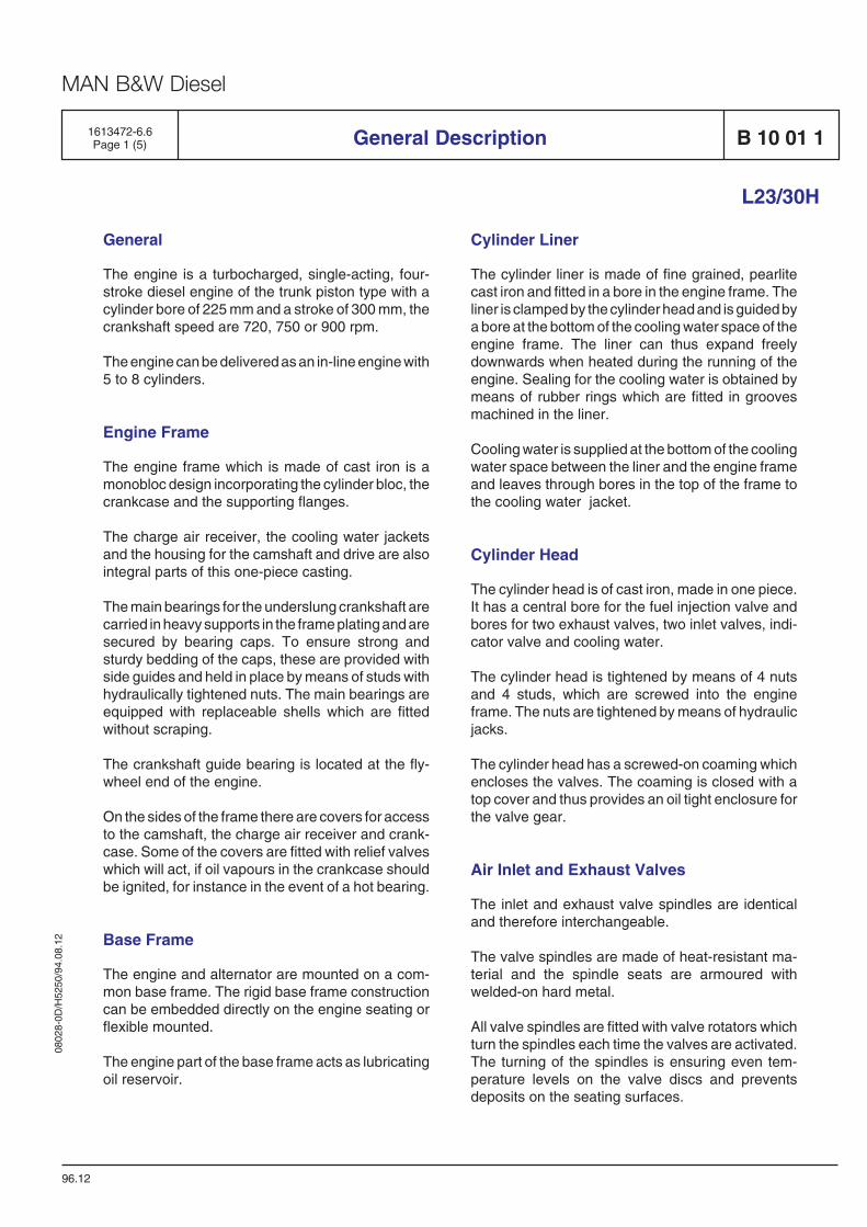
General
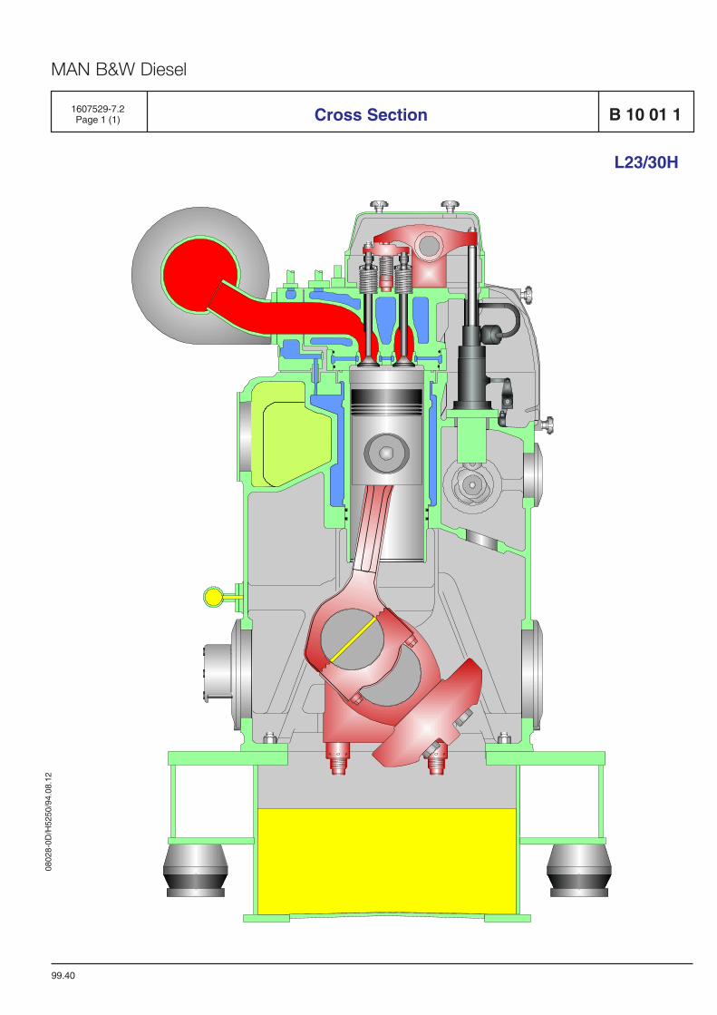
The engine is a turbocharged, single-acting, four-stroke diesel engine of the trunk piston type with acylinder bore of 225 mm and a stroke of 300 mm, thecrankshaft speed are 720, 750 or 900 rpm.
The engine can be delivered as an in-line engine with5 to 8 cylinders.
Engine Frame
The engine frame which is made of cast iron is amonobloc design incorporating the cylinder bloc, thecrankcase and the supporting flanges.
The charge air receiver, the cooling water jacketsand the housing for the camshaft and drive are alsointegral parts of this one-piece casting.
The main bearings for the underslung crankshaft arecarried in heavy supports in the frame plating and aresecured by bearing caps. To ensure strong andsturdy bedding of the caps, these are provided withside guides and held in place by means of studs withhydraulically tightened nuts. The main bearings areequipped with replaceable shells which are fittedwithout scraping.
The crankshaft guide bearing is located at the fly-wheel end of the engine.
On the sides of the frame there are covers for accessto the camshaft, the charge air receiver and crank-case. Some of the covers are fitted with relief valveswhich will act, if oil vapours in the crankcase shouldbe ignited, for instance in the event of a hot bearing.
Base Frame
The engine and alternator are mounted on a com-mon base frame. The rigid base frame constructioncan be embedded directly on the engine seating orflexible mounted.
The engine part of the base frame acts as lubricatingoil reservoir.
General Description B 10 01 1
96.12
L23/30H
1613472-6.6Page 1 (5)
Cylinder Liner
The cylinder liner is made of fine grained, pearlitecast iron and fitted in a bore in the engine frame. Theliner is clamped by the cylinder head and is guided bya bore at the bottom of the cooling water space of theengine frame. The liner can thus expand freelydownwards when heated during the running of theengine. Sealing for the cooling water is obtained bymeans of rubber rings which are fitted in groovesmachined in the liner.
Cooling water is supplied at the bottom of the coolingwater space between the liner and the engine frameand leaves through bores in the top of the frame tothe cooling water jacket.
Cylinder Head
The cylinder head is of cast iron, made in one piece.It has a central bore for the fuel injection valve andbores for two exhaust valves, two inlet valves, indi-cator valve and cooling water.
The cylinder head is tightened by means of 4 nutsand 4 studs, which are screwed into the engineframe. The nuts are tightened by means of hydraulicjacks.
The cylinder head has a screwed-on coaming whichencloses the valves. The coaming is closed with atop cover and thus provides an oil tight enclosure forthe valve gear.
Air Inlet and Exhaust Valves
The inlet and exhaust valve spindles are identicaland therefore interchangeable.
The valve spindles are made of heat-resistant ma-terial and the spindle seats are armoured withwelded-on hard metal.
All valve spindles are fitted with valve rotators whichturn the spindles each time the valves are activated.The turning of the spindles is ensuring even tem-perature levels on the valve discs and preventsdeposits on the seating surfaces.
0802
8-0D
/H52
50/9
4.08
.12
MAN B&W Diesel
The cylinder head is equipped with replaceablevalve seat rings, which are directly water cooled inorder to assure low valve temperatures.
The seat rings are made of heat-resistant steel. Theseting surfaces are hardened in order to minimizewear and prevent dent marks, on the inlet seat byinduction hardening, on the exhaust seat by hardmetal armouring.
Valve Actuating Gear
The rocker arms are actuated through rollers, rollerguides and push rods. The roller guide for fuel pumpand for inlet and exhaust valves are mounted in onecommon housing for each cylinder. This housing isbolted to the engine frame.
Each rocker arm activates two spindles through aspring-loaded valve bridge with thrust screws andadjusting screws for valve clearance.
The valve actuating gear is pressure-feed lubricatedfrom the centralized lubricating system of the engi-ne. A non-return valve blocks the oil inlet to therocker arms during prelubricating.
Fuel Injection System
The engine is provided with one fuel injection pump,an injection valve, and a high pressure pipe for eachcylinder.
The injection pump is mounted on the valve gearhousing by means of two screws. The pump consistsof a pump housing, a centrally placed pump barreland a plunger. The pump is activated by the fuel cam,and the volume injected is controlled by turning theplunger.
The fuel injection valve is located in a valve sleeve inthe center of the cylinder head. The opening of thevalve is controlled by the fuel oil pressure, and thevalve is closed by a spring.
The high pressure pipe which is led through a borein the cylinder head is surrounded by a shielding
B 10 01 1 General Description
96.12
L23/30H
1613472-6.6Page 2 (5)
tube.
The shielding tube has two holes in order to ensurethat any leakage will be drained off to the cylinderhead bore. The bore is equipped with drain channeland pipe.
The complete injection equipment inclusive injectionpumps, high pressure and low pressure pipes is wellenclosed behind removable covers.
Piston
The piston, which is oil-cooled and of the monobloctype made of nodular cast-iron, is equipped with 3compression rings and 1 oil scraper ring.
By the use of compression rings with different barrel-shaped profiles and chrome-plated running sur-faces, the piston ring pack is optimized for maximumsealing effect and minimum wear rate.
The piston has a cooling oil space close to the pistoncrown and the piston ring zone. The heat transferand thus the cooling effect is based on the shakereffect arising during the piston movement. Thecooling medium is oil from the engine's lubricating oilsystem.
Oil is supplied to the cooling oil space throughchannels from the oil grooves in the piston pinbosses. Oil is drained from the cooling oil spacethrough ducts situated diametrically to the inletchannels.
The piston pin is fully floating and kept in position inaxial direction by two circlips (seeger rings). Thepiston pin is equipped with channels and holes forsupply of oil to lubrication of the pin bosses and forsupply of cooling oil to the piston.
Connecting Rod
The connecting rod is die-forged. The big-end has aninclined joint in order to facilitate the piston andconnecting rod assembly to be withdrawn upthrough the cylinder liner. The joint faces on connec-ting rod and bearing cap are serrated to ensure
0802
8-0D
/H52
50/9
4.08
.12
MAN B&W Diesel
precise location and to prevent relative movement ofthe parts.
The connecting rod has bored channels for supply ofoil from the big-end to the small-end.
The big-end bearing is of the trimetal type coatedwith a running layer.
The bearing shells are of the precision type and aretherefore to be fitted without scraping or any otherkind of adaption.
The small-end bearing is of trimetal type and ispressed into the connecting rod. The bush is equip-ped with an inner circumferential groove, and apocket for distribution of oil in the bush itself and forsupply of oil to the pin bosses.
Crankshaft and Main Bearings
The crankshaft, which is a one-piece forging, issuspended in underslung bearings. The main bea-rings are of the trimetal type, which are coated witha running layer. To attain a suitable bearing pressureand vibration level the crankshaft is provided withcounterweights, which are attached to the crank-shaft by means of two screws.
At the flywheel end the crankshaft is fitted with a gearwheel which through an intermediate wheel drivesthe camshaft.
Also fitted here is a coupling flange for connection ofa generator. At the opposite end (front end) there isa claw-type coupling for the lub. oil pump or a flexiblegear wheel connection for lub. oil and water pumps.
Lubricating oil for the main bearings is suppliedthrough holes drilled in the engine frame. From themain bearings the oil passes through bores in thecrankshaft to the big-end bearings and hencethrough channels in the connecting rods to lubricatethe piston pins and cool the pistons.
Camshaft and Camshaft Drive
The inlet and exhaust valves as well as the fuelpumps of the engine are actuated by a camshaft.
General Description B 10 01 1
96.12
L23/30H
1613472-6.6Page 3 (5)
The camshaft is placed in the engine frame at thecontrol side (left side, seen from the flywheel end).
The camshaft is driven by a gear wheel on thecrankshaft through an intermediate wheel, and rota-tes of a speed which is half of that of the crankshaft.
The camshaft is located in bearing bushes which arefitted in bores in the engine frame, each bearing isreplaceable and locked in position in the engineframe by means of a locking screw.
A guidering mounted at the flywheel end guides thecamshaft in the longitudinal direction.
Each section is equipped with fixed cams for opera-tion of fuel pump, air inlet valve and exhaust valve.
The foremost section is equipped with a splined shaftcoupling for driving the fuel oil feed pump (ifmounted). The gear wheel for driving the camshaftas well as a gear wheel connection for the governordrive are screwed on to the aftmost section.
The lubricating oil pipes for the gear wheels are e-quipped with nozzles which are adjusted to apply theoil at the points where the gear wheels are in mesh.
Governor
The engine speed is controlled by a hydraulic orelectric governor.
Monitoring and Control System
All media systems are equipped with thermometersand manometers for local reading and for the mostessential pressures the manometers are togetherwith tachometers centralized in an engine-mountedinstruments panel.
The number of and type of parameters to have alarmfunction are chosen in accordance with the require-ments from the classification societies.
The engine has as standard shut-down functions forlubricating oil pressure low, cooling water tempera-
0802
8-0D
/H52
50/9
4.08
.12
MAN B&W Diesel
B 10 01 1
ture high and for overspeed.
Turbocharger System
The turbocharger system of the engine, which is aconstant pressure system, consists of an exhaustgas receiver, a turbocharger, a charging air coolerand a charging air receiver, the latter being inter-grated in the engine frame.
The turbine wheel of the turbocharger is driven bythe engine exhaust gas, and the turbine wheel drivesthe turbocharger compressor, which is mounted onthe common shaft. The compressor draws air fromthe engine room, through the air filters.
The turbocharger presses the air through the char-ging air cooler to the charging air receiver. From thecharging air receiver, the air flows to each cylinder,through the inlet valves.
The charging air cooler is a compact tube-typecooler with a large cooling surface. The coolingwater is passed twice through the cooler, the endcovers being designed with partitions which causethe cooling water to turn.
The cooling water tubes are fixed to the tube platesby expansion.
From the exhaust valves, the exhaust is led througha water cooled intermediate piece to the exhaust gasreceiver where the pulsatory pressure from the indi-vidual exhaust valves is equalized and passed to theturbocharger as a constant pressure, and further tothe exhaust outlet and silencer arrangement.
The exhaust gas receiver is made of pipe sections,one for each cylinder, connected to each other, bymeans of compensators, to prevent excessivestress in the pipes due to heat expansion.
In the cooled intermediate piece a thermometer forreading the exhaust gas temperature is fitted andthere is also possibility of fitting a sensor for remotereading.
To avoid excessive thermal loss and to ensure areasonably low surface temperature the exhaust gas
General Description
96.12
L23/30H
1613472-6.6Page 4 (5)
receiver is insulated.
Compressed Air System
The engine is started by means of a built-on airstarter.
The compressed air system comprises a main star-ting valve, an air strainer, a remote controlled star-ting valve and an emergency starting valve which willmake it possible to start the engine in case of a powerfailure.
Fuel Oil System
The built-on fuel oil system consists of the fuel oilfilter and the fuel injection system. An engine-drivenfuel oil feed pump can be mounted as optional.
The fuel oil feed pump, which is of the gear pumptype, is mounted to the front end of the engine frameand driven by the camshaft through a splined shaftcoupling, the pump housing is equipped with aspring-loaded adjustable by-pass valve.
The fuel oil filter is a duplex filter. The filter isequipped with a three-way cock for single or doubleoperation of the filters.
Waste oil and fuel oil leakage is led to a leakagealarm which is heated by means of fuel return oil.
Lubricating Oil System
All moving parts of the engine are lubricated with oilcirculating under pressure.
The lubricating oil pump is of the gear wheel type withbuilt-in pressure control valve. The pump draws theoil from the sump in the base frame, and on thepressure side the oil passes through the lubricatingoil cooler and the filter which both are mounted on theengine.
Cooling is carried out by the low temperature coolingwater system and the temperature regulating ismade by a thermostatic 3-way valve on the oil side.
0802
8-0D
/H52
50/9
4.08
.12
MAN B&W Diesel
The engine is as standard equipped with an electri-cally driven prelubricating pump.
Cooling Water System
The cooling water system consists of a low tempe-rature system and a high temperature system.
The water in the low temperature system is passed
General Description B 10 01 1
96.12
L23/30H
1613472-6.6Page 5 (5)
through the charge air cooler and the lubricating oilcooler, and the alternator if the latter is water cooled.The low temperature system is normally cooled byfresh water.
The high temperature cooling water system coolsthe engine cylinders and the cylinder head. The hightemperature system is always cooled by fresh water.
Tools
The engine can be delivered with all necessary toolsfor overhaul, for each specific plant, most of the toolscan be arranged on steel plate panels.

0802
8-0D
/H52
50/9
4.08
.12
MAN B&W Diesel
99.40
Cross Section B 10 01 1
L23/30H
1607529-7.2Page 1 (1)

0802
8-0D
/H52
50/9
4.08
.12
MAN B&W Diesel
Main Particulars B 10 01 11609517-6.8Page 1 (1)
L23/30H
05.17
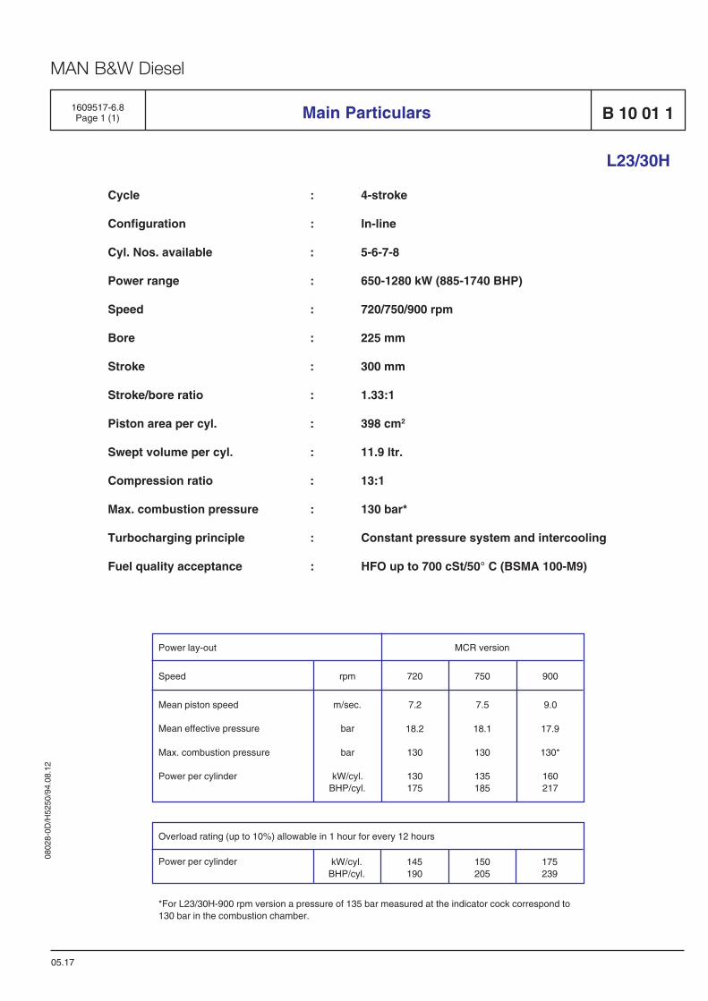
Cycle : 4-stroke
Configuration : In-line
Cyl. Nos. available : 5-6-7-8
Power range : 650-1280 kW (885-1740 BHP)
Speed : 720/750/900 rpm
Bore : 225 mm
Stroke : 300 mm
Stroke/bore ratio : 1.33:1
Piston area per cyl. : 398 cm2
Swept volume per cyl. : 11.9 ltr.
Compression ratio : 13:1
Max. combustion pressure : 130 bar*
Turbocharging principle : Constant pressure system and intercooling
Fuel quality acceptance : HFO up to 700 cSt/50° C (BSMA 100-M9)
Power lay-out
Speed
Mean piston speed
Mean effective pressure
Max. combustion pressure
Power per cylinder
rpm
m/sec.
bar
bar
kW/cyl.BHP/cyl.
900
9.0
17.9
130*
160217
720
7.2
18.2
130
130175
750
7.5
18.1
130
135185
MCR version
Power per cylinder kW/cyl.BHP/cyl.
145190
150205
175239
Overload rating (up to 10%) allowable in 1 hour for every 12 hours
*For L23/30H-900 rpm version a pressure of 135 bar measured at the indicator cock correspond to130 bar in the combustion chamber.

0802
8-0D
/H52
50/9
4.08
.12
MAN B&W Diesel
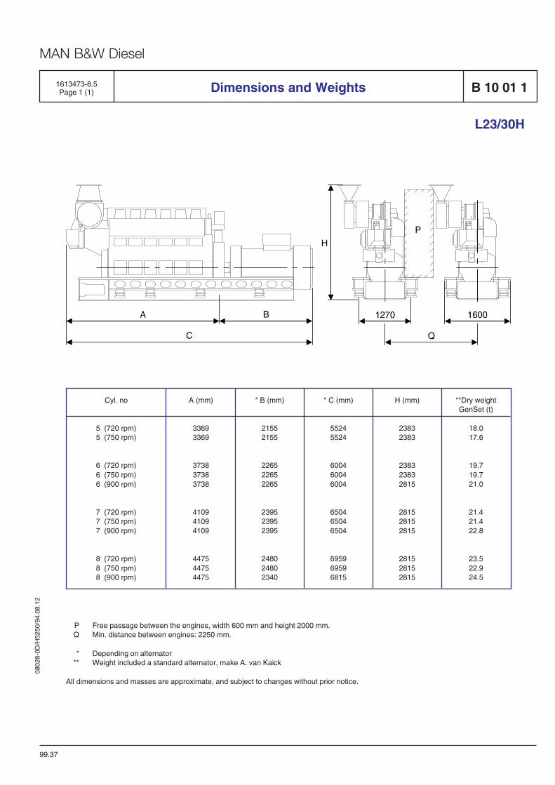
1613473-8.5Page 1 (1) Dimensions and Weights B 10 01 1
99.37
L23/30H
P Free passage between the engines, width 600 mm and height 2000 mm.Q Min. distance between engines: 2250 mm.
* Depending on alternator** Weight included a standard alternator, make A. van Kaick
All dimensions and masses are approximate, and subject to changes without prior notice.
Cyl. no
5 (720 rpm)5 (750 rpm)
6 (720 rpm)6 (750 rpm)6 (900 rpm)
7 (720 rpm)7 (750 rpm)7 (900 rpm)
8 (720 rpm)8 (750 rpm)8 (900 rpm)
**Dry weightGenSet (t)
18.017.6
19.719.721.0
21.421.422.8
23.522.924.5
A (mm)
33693369
373837383738
410941094109
447544754475
* B (mm)
21552155
226522652265
239523952395
248024802340
* C (mm)
55245524
600460046004
650465046504
695969596815
H (mm)
23832383
238323832815
281528152815
281528152815

0802
8-0D
/H52
50/9
4.08
.12
MAN B&W Diesel
92.26
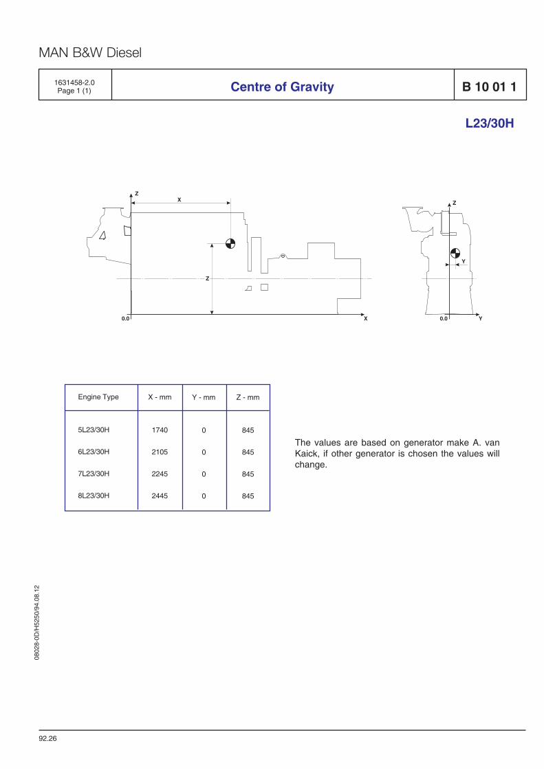
Centre of Gravity1631458-2.0Page 1 (1) B 10 01 1
L23/30H
Z
Y
Y
0.0
ZX
X0.0
Z
Engine Type
5L23/30H
6L23/30H
7L23/30H
8L23/30H
X - mm
1740
2105
2245
2445
Y - mm
0
0
0
0
Z - mm
845
845
845
845
The values are based on generator make A. vanKaick, if other generator is chosen the values willchange.

0802
8-0D
/H52
50/9
4.08
.12
MAN B&W Diesel
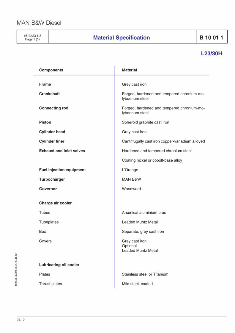
1613423-6.3Page 1 (1)
L23/30H
Components
Frame
Crankshaft
Connecting rod
Piston
Cylinder head
Cylinder liner
Exhaust and inlet valves
Fuel injection equipment
Turbocharger
Governor
Charge air cooler
Tubes
Tubeplates
Box
Covers
Lubricating oil cooler
Plates
Thrust plates
Material
Grey cast iron
Forged, hardened and tempered chronium-mo-lybdenum steel
Forged, hardened and tempered chronium-mo-lybdenum steel
Spheroid graphite cast iron
Grey cast iron
Centrifugally cast iron copper-vanadium alloyed
Hardened and tempered chronium steel
Coating nickel or cobolt-base alloy
L'Orange
MAN B&W
Woodward
Arsenical aluminium bras
Leaded Muntz Metal
Separate, grey cast iron
Grey cast ironOptionalLeaded Muntz Metal
Stainless steel or Titanium
Mild steel, coated
Material Specification B 10 01 1
94.10

0802
8-0D
/H52
50/9
4.08
.12
MAN B&W Diesel
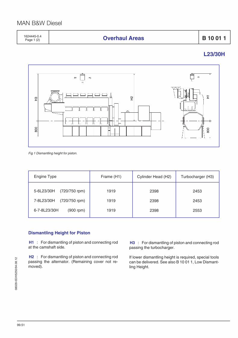
Overhaul Areas1624445-0.4Page 1 (2) B 10 01 1
L23/30H
99.51
Engine Type
5-6L23/30H (720/750 rpm)
7-8L23/30H (720/750 rpm)
6-7-8L23/30H (900 rpm)
Frame (H1)
1919
1919
1919
Cylinder Head (H2)
2398
2398
2398
Turbocharger (H3)
2453
2453
2553
Dismantling Height for Piston
H1 : For dismantling of piston and connecting rodat the camshaft side.
H2 : For dismantling of piston and connecting rodpassing the alternator. (Remaining cover not re-moved).
Fig 1 Dismantling height for piston.
H3 : For dismantling of piston and connecting rodpassing the turbocharger.
If lower dismantling height is required, special toolscan be delivered. See also B 10 01 1, Low Dismant-ling Height.
0802
8-0D
/H52
50/9
4.08
.12
MAN B&W Diesel
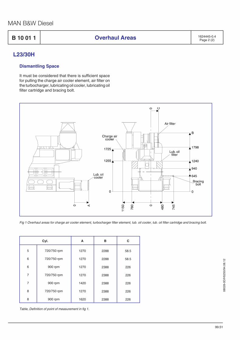
B 10 01 1 Overhaul Areas
L23/30H
Dismantling Space
It must be considered that there is sufficient spacefor pulling the charge air cooler element, air filter onthe turbocharger, lubricating oil cooler, lubricating oilfilter cartridge and bracing bolt.
Fig 1 Overhaul areas for charge air cooler element, turbocharger filter element, lub. oil cooler, lub. oil filter cartridge and bracing bolt.
5
6
6
7
7
8
8
Cyl. A B C
1270
1270
1270
1270
1420
1270
1620
720/750 rpm
720/750 rpm
900 rpm
720/750 rpm
900 rpm
720/750 rpm
900 rpm
1624445-0.4Page 2 (2)
99.51
2288
2288
2388
2388
2388
2388
2388
58.5
58.5
226
226
226
226
226
Table, Definition of point of measurement in fig 1.
0802
8-0D
/H52
50/9
4.08
.12
MAN B&W Diesel
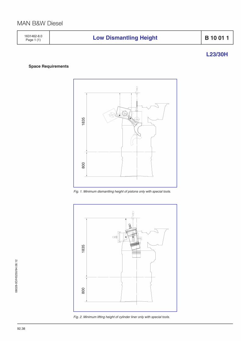
92.38
Space Requirements
L23/30H
1835
800
Fig. 1. Minimum dismantling height of pistons only with special tools.
1835
800
Fig. 2. Minimum lifting height of cylinder liner only with special tools.
1631462-8.0Page 1 (1) B 10 01 1Low Dismantling Height

0802
8-0D
/H52
50/9
4.08
.12
MAN B&W Diesel
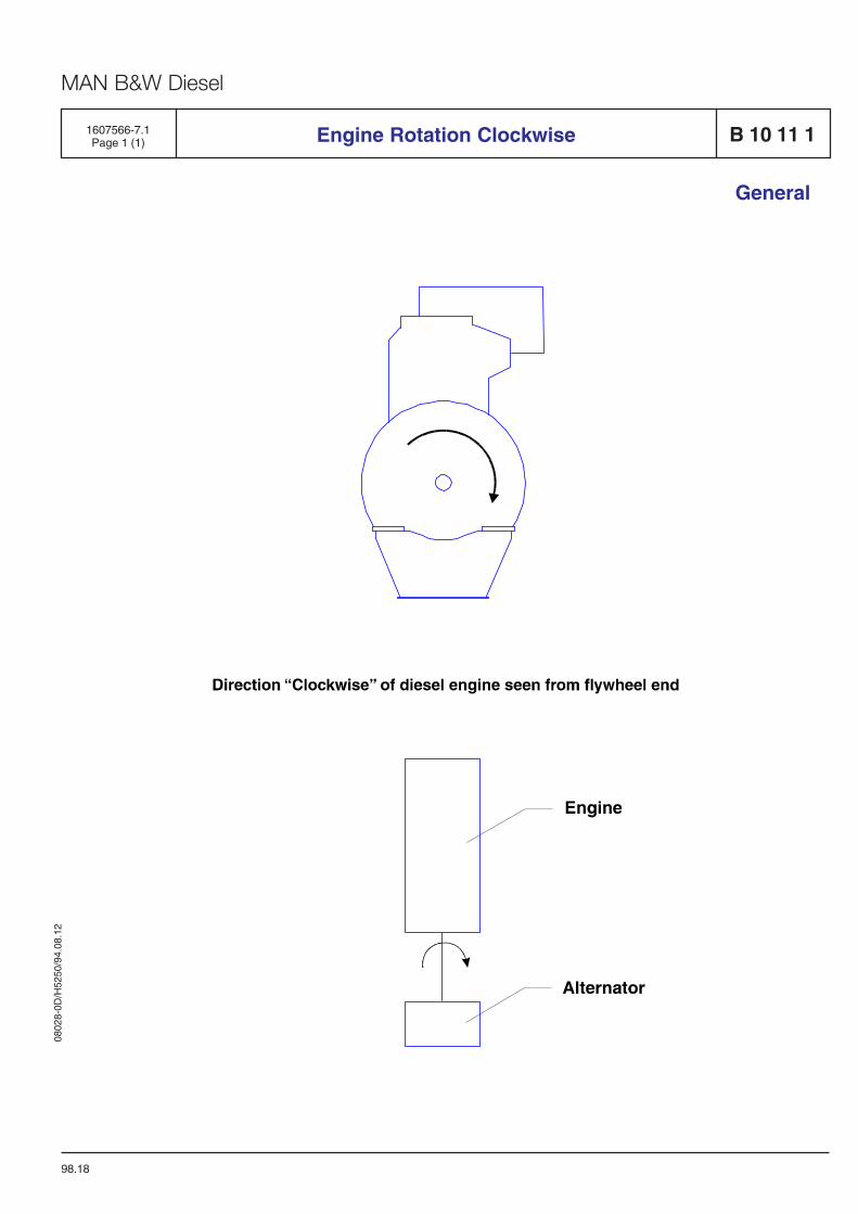
1607566-7.1Page 1 (1) Engine Rotation Clockwise B 10 11 1
General
98.18


Fuel Oil System
B 11

0802
8-0D
/H52
50/9
4.08
.12
MAN B&W Diesel
1613570-8.7Page 1 (2) B 11 00 0
L23/30H
Internal Fuel Oil System
05.43
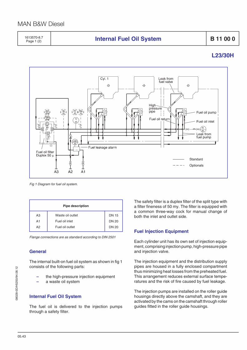
Fig 1 Diagram for fuel oil system.
Pipe description
DN 15
DN 20
DN 20
Waste oil outlet
Fuel oil inlet
Fuel oil outlet
A3
A1
A2
Flange connections are as standard according to DIN 2501
The safety filter is a duplex filter of the split type witha filter fineness of 50 my. The filter is equipped witha common three-way cock for manual change ofboth the inlet and outlet side.
Fuel Injection Equipment
Each cylinder unit has its own set of injection equip-ment, comprising injection pump, high-pressure pipeand injection valve.
The injection equipment and the distribution supplypipes are housed in a fully enclosed compartmentthus minimizing heat losses from the preheated fuel.This arrangement reduces external surface tempe-ratures and the risk of fire caused by fuel leakage.
The injection pumps are installed on the roller guidehousings directly above the camshaft, and they areactivated by the cams on the camshaft through rollerguides fitted in the roller guide housings.
General
The internal built-on fuel oil system as shown in fig 1consists of the following parts:
– the high-pressure injection equipment– a waste oil system
Internal Fuel Oil System
The fuel oil is delivered to the injection pumpsthrough a safety filter.
0802
8-0D
/H52
50/9
4.08
.12
MAN B&W Diesel
The amount of fuel injected into each cylinder unit isadjusted by means of the governor, which maintainsthe engine speed at the preset value by a continuouspositioning of the fuel pump racks, via a commonregulating shaft and spring-loaded linkages for eachpump.
The injection valve is for "deep" building-in to thecentre of the cylinder head.
The injection oil is supplied from the injection pumpto the injection valve via a double-walled pressurepipe installed in a bore, in the cylinder head.
This bore has an external connection to conduct theleak oil from the injection valve and high-pressurepipe to the waste oil system.
A bore in the cylinder head vents the space below thebottom rubber sealing ring on the injection valve,thus preventing any pressure build-up due to gasleakage, but also unveiling any malfunction of thebottom rubber sealing ring for leak oil.
Waste Oil System
Waste and leak oil from the comparements, fuelvalves is led to a fuel leakage alarm unit.
The alarm unit consists of a box with a float switch forlevel monitoring. In case of a larger than normalleakage, the float switch will initiate alarm. Thesupply fuel oil to the engine is lead through the unitin order to keep this heated up, thereby ensuring freedrainage passage even for high-viscous waste/leakoil.
B 11 00 0
L23/30H
Internal Fuel Oil System 1613570-8.7Page 2 (2)
05.43
Optionals
Besides the standard components, the followingstandard optionals can be built-on:
Pressure differential alarm high– PDAH 43-40 Fuel oil, inlet and outlet filter
Pressure differential transmitting– PDT 43-40 Fuel oil, inlet and outlet filter
Pressure alarm low– PAL 40 Fuel oil, inlet fuel oil pump
Pressure transmitting– PT40 Fuel oil, inlet fuel oil pump
Temperature element– TE40 Fuel oil, inlet fuel oil pump
Data
For pump capacities, see D 10 05 0 "List of Capa-cities".
Set points and operating levels for temperature andpressure are stated in B 19 00 0 "Operating Data andSet Points".
0802
8-0D
/H52
50/9
4.08
.12
MAN B&W Diesel
General
Fuel Oil Diagram B 11 00 01624468-9.8Page 1 (3)
06.08
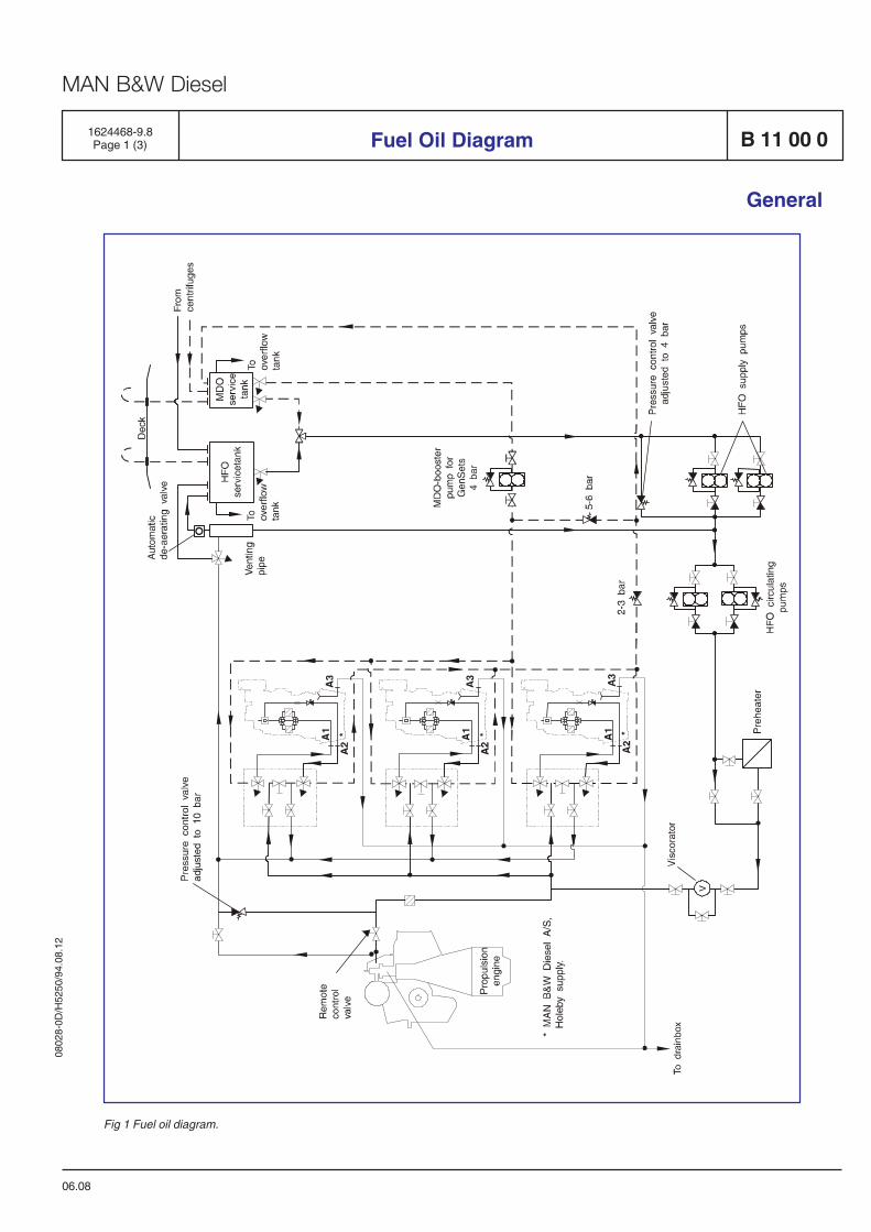
Fig 1 Fuel oil diagram.
0802
8-0D
/H52
50/9
4.08
.12
MAN B&W Diesel
1624468-9.8Page 2 (3)B 11 00 0
General
Fuel Oil Diagram
Uni-Fuel
The fuel system on page 1 is designed as a uni-fuelsystem, which means that the propulsion engine andthe GenSets are running on the same fuel oil and arefed from the common fuel feed system. The uni-fuelconcept is a unique foundation for substantial savingsin operating costs and it is also the simplest fuelsystem, resulting in lower maintenance and easieroperation.
The diagram on page 1 is a guidance. It has to beadapted in each case to the actual engine and pipelay-out.
Fuel Feed System
The common fuel feed system is a pressurizedsystem, consisting of HFO supply pumps, HFOcirculating pumps, preheater and equipment forcontrolling the viscosity, (e.g. a viscorator as shown).
From the service tank, the oil is led to one of theelectrically driven supply pumps, which deliver theoil with a pressure of approximately 4 bar to the lowpressure side of the fuel oil system, thus avoidingboiling of the fuel in the venting tank in the temperaturerange applied.
From the low pressure part of the fuel system, thefuel oil is led to an electrically driven circulatingpump, which pumps the fuel through a preheater tothe engines. For the propulsion engine please seethe specific plant specifications. The internal fuelsystem for the GenSets is shown in B 11 00 0"Internal Fuel Oil System".
It is recommended to place a safety duplex filter witha fineness of max. 50 µm as close as possible toeach engine as shown at the fuel oil diagram. It ispossible, however not our standard/recommen-dations, to place a common fuel oil safety duplexfilter and a common MDO filter for the entire GenSetinstallation. In this case it must be ensured that thefuel oil system fullfil the classification rules andprotect the engines from impurities.
Note: a filter surface load of 1 l/cm2. hour must not beexceeded.
The venting tank is connected to the service tank viaan automatic de-aerating valve, which will releaseany gases present.
To ensure ample filling of the fuel injection pumps,the capacity of the electrically driven circulatingpumps must be 3 times higher than the amount offuel, consumed by the diesel engine at 100% load.The surplus amount of fuel oil is re-circulated throughthe engine and back through the venting tank.
To ensure a constant fuel pressure to the fuel injectionpumps during all engine loads, a spring-loadedoverflow is inserted in the fuel system.
The circulating pump pressure should be as specifiedin "B 19 00 0, Operating Data & Set Points" whichprovides a pressure margin against gasification andcavitation in the fuel system even at a temperature of150°C.
The circulating pumps will always be running, evenif the propulsion engine and one or several of theGenSets are stopped. This is in order to circulateheated heavy fuel oil through the fuel system on theengine(s), thereby keeping them ready to start withpreheated fuel injection pumps and the fuel valvesde-aerated.
In order to minimize the power consumption whenthe propulsion engine(s) is stopped, the main HFOsupply pump can be stopped and the port pumps canbe started.
MDO Operation
The MDO to the GenSets is delivered from a separatepipeline from the service tank by means of a boosterpump.
The pump capacity of the MDO pump must be 3times higher than the amount of MDO, consumed bythe diesel engines at 100% load.
The system is designed in such a way that the fueltype for the GenSets can be changed independent ofthe fuel supply to the propulsion engine.
06.08
0802
8-0D
/H52
50/9
4.08
.12
MAN B&W Diesel
As an optional, the GenSet plant can be deliveredwith the fuel changing system, consisting of a set ofremotely controlled, pneumatically actuated 3-wayfuel changing valves for each GenSet and a fuelchanging valve control box common for all GenSets.A separate fuel changing system for each GenSetgives the advantage of individually choosing MDO orHFO mode.
Such a change-over may become necessary, forinstance, if the engine(s) has to be:
– stopped for a prolonged period.– stopped for major repairs of the fuel system,
etc.
If the fuel type for the propulsion engine has to bechanged from HFO to MDO, then the 3-way valvesimmediately after the service tanks have to bechanged.
06.08
General
Fuel Oil Diagram1624468-9.8Page 3 (3) B 11 00 0
Emergency Start
Further, the MDO must be available as a fuel inemergency situations.
If a black-out occurs, starting up the auxiliary engineson MDO can be seen in three ways:
– The MDO is supplied from the MDO boosterpump which can be driven pneumatically orelectrically. If the pump is driven electrically itmust be connected to the emergencyswitchboard.
– If the engine has a built-on booster pump, itcan be used if the minimum level in the MDOservice tank corresponds to or is max. 1.0 mbelow the level of the built-on pump. However,in the design of the entire system, level of theservice tank under the engine can causeproblems with vacuum in the system.
– If not a gravity tank (100 - 200 l) may bearranged above the engine.
If no pumps are available, it is possible to start up theengine if a tank - as mentioned above - is placedminimum 8 meters above the engine. However, onlyif the change-over valve is placed as near as possibleto the engine.

0802
8-0D
/H52
50/9
4.08
.12
MAN B&W Diesel
General
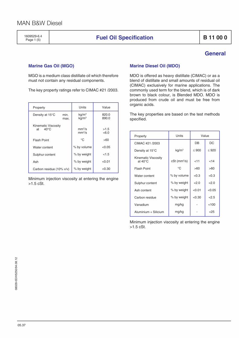
Marine Gas Oil (MGO)
MGO is a medium class distillate oil which thereforemust not contain any residual components.
The key property ratings refer to CIMAC #21 /2003.
05.37
Fuel Oil Specification B 11 00 01609529-6.4Page 1 (5)
Marine Diesel Oil (MDO)
MDO is offered as heavy distillate (CIMAC) or as ablend of distillate and small amounts of residual oil(CIMAC) exclusively for marine applications. Thecommonly used term for the blend, which is of darkbrown to black colour, is Blended MDO. MDO isproduced from crude oil and must be free fromorganic acids.
The key properties are based on the test methodsspecified.
Property
CIMAC #21 /2003
Density at 15°C
Kinematic Viscosityat 40°C
Flash Point
Water content
Sulphur content
Ash content
Carbon residue
Vanadium
Aluminium + Silicium
Value
DB DC
≤ 900 ≤ 920
<11 <14
>60 >60
<0.3 <0.3
<2.0 <2.0
<0.01 <0.05
<0.30 <2.5
- <100
- <25
Units
kg/m3
cSt (mm2/s)
°C
% by volume
% by weight
% by weight
% by weight
mg/kg
mg/kg
Minimum injection viscosity at entering the engine>1.5 cSt.
Minimum injection viscosity at entering the engine>1.5 cSt.
Property
Density at 15°C min.max.
Kinematic Viscosityat 40°C
Flash Point
Water content
Sulphur content
Ash
Carbon residue (10% v/v)
Value
820.0890.0
>1.5<6.0
>60
<0.05
<1.5
<0.01
<0.30
Units
kg/m3
kg/m3
mm2/smm2/s
°C
% by volume
% by weight
% by weight
% by weight
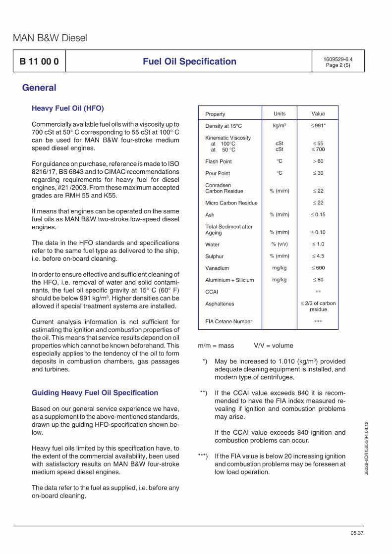
0802
8-0D
/H52
50/9
4.08
.12
MAN B&W Diesel
B 11 00 0 1609529-6.4Page 2 (5)Fuel Oil Specification
General
05.37
Heavy Fuel Oil (HFO)
Commercially available fuel oils with a viscosity up to700 cSt at 50° C corresponding to 55 cSt at 100° Ccan be used for MAN B&W four-stroke mediumspeed diesel engines.
For guidance on purchase, reference is made to ISO8216/17, BS 6843 and to CIMAC recommendationsregarding requirements for heavy fuel for dieselengines, #21 /2003. From these maximum acceptedgrades are RMH 55 and K55.
It means that engines can be operated on the samefuel oils as MAN B&W two-stroke low-speed dieselengines.
The data in the HFO standards and specificationsrefer to the same fuel type as delivered to the ship,i.e. before on-board cleaning.
In order to ensure effective and sufficient cleaning ofthe HFO, i.e. removal of water and solid contami-nants, the fuel oil specific gravity at 15° C (60° F)should be below 991 kg/m3. Higher densities can beallowed if special treatment systems are installed.
Current analysis information is not sufficient forestimating the ignition and combustion properties ofthe oil. This means that service results depend on oilproperties which cannot be known beforehand. Thisespecially applies to the tendency of the oil to formdeposits in combustion chambers, gas passagesand turbines.
Guiding Heavy Fuel Oil Specification
Based on our general service experience we have,as a supplement to the above-mentioned standards,drawn up the guiding HFO-specification shown be-low.
Heavy fuel oils limited by this specification have, tothe extent of the commercial availability, been usedwith satisfactory results on MAN B&W four-strokemedium speed diesel engines.
The data refer to the fuel as supplied, i.e. before anyon-board cleaning.
m/m = mass V/V = volume
*) May be increased to 1.010 (kg/m3) providedadequate cleaning equipment is installed, andmodern type of centrifuges.
**) If the CCAI value exceeds 840 it is recom-mended to have the FIA index measured re-vealing if ignition and combustion problemsmay arise.
If the CCAI value exceeds 840 ignition andcombustion problems can occur.
***) If the FIA value is below 20 increasing ignitionand combustion problems may be foreseen atlow load operation.
Property
Density at 15°C
Kinematic Viscosityat 100°Cat 50 °C
Flash Point
Pour Point
ConradsenCarbon Residue
Micro Carbon Residue
Ash
Total Sediment afterAgeing
Water
Sulphur
Vanadium
Aluminium + Silicium
CCAI
Asphaltenes
FIA Cetane Number
Value
≤ 991*
≤ 55≤ 700
> 60
≤ 30
≤ 22
≤ 22
≤ 0.15
≤ 0.10
≤ 1.0
≤ 4.5
≤ 600
≤ 80
∗∗
≤ 2/3 of carbonresidue
∗∗∗
Units
kg/m3
cStcSt
°C
°C
% (m/m)
% (m/m)
% (m/m)
% (v/v)
% (m/m)
mg/kg
mg/kg
0802
8-0D
/H52
50/9
4.08
.12
MAN B&W Diesel
1609529-6.4Page 3 (5) Fuel Oil Specification B 11 00 0
05.37
General
If heavy fuel oils, with analysis data exceeding thebesides figures, are to be used, especially withregard to viscosity and specific gravity, the enginebuilder should be contacted for advice regardingpossible changes in the fuel oil system.
Blends
Fuel oil containing used lubricating oil (ULO) has tocomply with the CIMAC #21/2003 fuel oil specifica-tion.
The admixing of used engine oil to the fuel involvesa substantial danger because the lubricating oiladditives have an emulsifying effect and keep dirt,water and catfines finely suspended. Therefore, theyimpede or preclude the necessary cleaning of thefuel. We ourselves and others have made the expe-rience that severe damage included by wear mayoccur to the engine and turbocharger componentsas a result.
The admixing of non-mineral oil constituents (suchas coal oil) and of residual products from refining orother processes (such as solvents) is harmfull to theengine! The reasons are, for example: the abrasiveand corrosive effects, the adverse combustion prop-erties, a poor compatibility with mineral oils and, lastbut not least, the negative environmental effects.The order letter for the fuel should expressly mentionwhat is prohibited, as this constraint has not yet beenincorporated in the commonly applied fuel specifica-tions.
The admixing of chemical waste materials (such assolvents) to the fuel is for reasons of environmentalprotection prohibited by resolution of the IMO MarineEnvironmental Protection Committee of 1 Jan. 92.
Vanadium / Sodium
Should the vanadium/sodium ratio be unfavourable,the melting temperature of the heavy fuel oil ash maydrop into the range of the exhaust valve temperaturewhich will result in high-temperature corrosion anddeposits build up. By precleaning the heavy fuel oilin the settling tank and in the centrifugal separators,the water, and with it the water-soluble sodiumcompounds can be largely removed.
If the sodium content is lower than 30% of thevanadium content, the risk of high-temperature cor-rosion will be small. It must also be prevented thatsodium in the form of sea water enters the enginetogether with the intake air.
If sodium content is higher than 100 mg/kg, anincrease of salt deposits is to be expected in thecombustion space and in the exhaust system. Thiscondition will have an adverse effect on engineoperation (among others, due to surging of theturbocharger).
Under certain conditions, high-temperature corro-sion may be prevented by a fuel additive that raisesthe melting temperature of the heavy fuel oil ash.
Ash
Heavy fuel oils with a high ash content in the form offoreign particles such as sand, corrosion elementsand catalyst fines (catfines) in heavy fuel oils comingfrom catalytic cracking processes. In most cases,these catfines will be aluminium oxides, siliciumoxides, which causes high wear in the injectionsystem and in the engine.
Sulphuric Acid Corrosion
The engine should be operated at the cooling watertemperatures specified in the operating manual forthe respective load. If the temperature of the compo-nent surface exposed to the acidic combustion gasesis below the acid dew point, acid corrosion canoccour.
Fuel Oil Condition, when entering the En-gine
As practically all fuel oil specifications including theabove standards refer to the same fuel type assupplied, the fuel supplied to a ship has to be treatedon board before use. For running on the oil qualitymentioned above it is necessary that equipmentexists on board, which can treat, respectively cleanand preheat, the fuel oil with optimum efficiency.
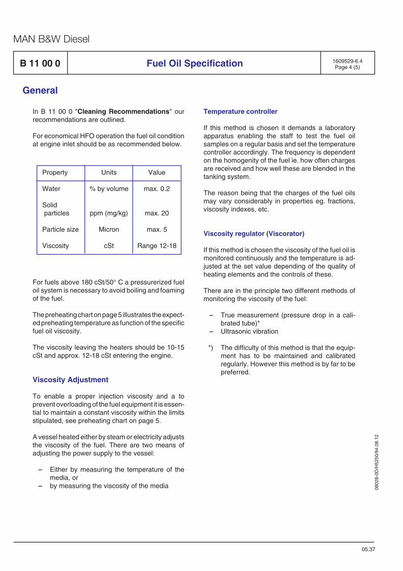
0802
8-0D
/H52
50/9
4.08
.12
MAN B&W Diesel
B 11 00 0 1609529-6.4Page 4 (5)Fuel Oil Specification
General
05.37
In B 11 00 0 "Cleaning Recommendations" ourrecommendations are outlined.
For economical HFO operation the fuel oil conditionat engine inlet should be as recommended below.
Property
Water
Solid particles
Particle size
Viscosity
Units
% by volume
ppm (mg/kg)
Micron
cSt
Value
max. 0.2
max. 20
max. 5
Range 12-18
For fuels above 180 cSt/50° C a pressurerized fueloil system is necessary to avoid boiling and foamingof the fuel.
The preheating chart on page 5 illustrates the expect-ed preheating temperature as function of the specificfuel oil viscosity.
The viscosity leaving the heaters should be 10-15cSt and approx. 12-18 cSt entering the engine.
Viscosity Adjustment
To enable a proper injection viscosity and a toprevent overloading of the fuel equipment it is essen-tial to maintain a constant viscosity within the limitsstipulated, see preheating chart on page 5.
A vessel heated either by steam or electricity adjuststhe viscosity of the fuel. There are two means ofadjusting the power supply to the vessel:
– Either by measuring the temperature of themedia, or
– by measuring the viscosity of the media
Temperature controller
If this method is chosen it demands a laboratoryapparatus enabling the staff to test the fuel oilsamples on a regular basis and set the temperaturecontroller accordingly. The frequency is dependenton the homogenity of the fuel ie. how often chargesare received and how well these are blended in thetanking system.
The reason being that the charges of the fuel oilsmay vary considerably in properties eg. fractions,viscosity indexes, etc.
Viscosity regulator (Viscorator)
If this method is chosen the viscosity of the fuel oil ismonitored continuously and the temperature is ad-justed at the set value depending of the quality ofheating elements and the controls of these.
There are in the principle two different methods ofmonitoring the viscosity of the fuel:
– True measurement (pressure drop in a cali-brated tube)*
– Ultrasonic vibration
*) The difficulty of this method is that the equip-ment has to be maintained and calibratedregularly. However this method is by far to bepreferred.
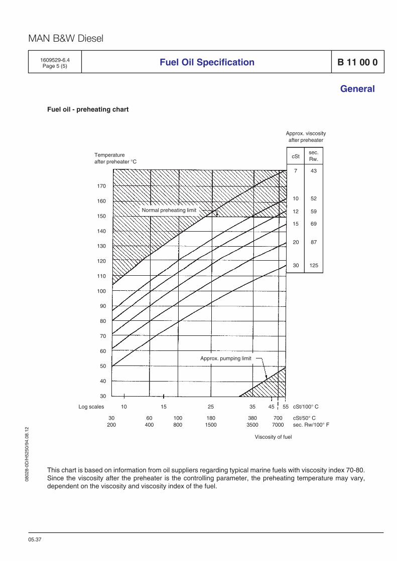
0802
8-0D
/H52
50/9
4.08
.12
MAN B&W Diesel
This chart is based on information from oil suppliers regarding typical marine fuels with viscosity index 70-80.Since the viscosity after the preheater is the controlling parameter, the preheating temperature may vary,dependent on the viscosity and viscosity index of the fuel.
Fuel oil - preheating chart
Normal preheating limit
Approx. pumping limit
10 15 25 35 45 55 cSt/100° C
30 60 100 180 380 700 cSt/50° C200 400 800 1500 3500 7000 sec. Rw/100° F
Viscosity of fuel
Log scales
Approx. viscosityafter preheater
Temperatureafter preheater °C
170
160
150
140
130
120
110
100
90
80
70
60
50
40
30
sec.Rw.cSt
7 43
10 52
12 59
20 87
15 69
30 125
B 11 00 01609529-6.4Page 5 (5) Fuel Oil Specification
General
05.37

0802
8-0D
/H52
50/9
4.08
.12
MAN B&W Diesel
1693520-5.2Page 1 (3)
General Considerations
The quality of a fuel oil is stated, in analysis data, interms of physical and chemical properties, which aredecisive to the suitability of the fuel oil for differentapplications. For diesel engine fuels the combustionquality, the content of impurities and the handlingproperties are the main quality criteria.
Since residual fuels are traded and designatedaccording to viscosity, it has become commonpractice to associate viscosity with quality. Thispractice can be very misleading, especially withmodern residual fuels, as a fuel oil of low viscositycan often be just as bad, or even worse, than otherfuel oils of very high viscosity.
The quality of refinery residues is dependent on theorigin of the crude oil, the grade of utilization whenrefining the crude oil, and the refinery techniqueused.
Some of the residues used in fuel oil production areof a viscosity requiring visbreaking, a process whichwill reduce the viscosity without improving the qualityat all.
When producing residual fuels from visbreaked,cracked residues and from "straight run" residues,the final adjustment of viscosity to fulfil therequirements of the different grades of intermediatefuels is achieved by adding gas oil.
However, it must be noted that considerable reductionof the viscosity is achieved by adding a relativelysmall amount of gas oil, which will give only a minorimprovement of the quality of the blend. This meansthat the quality to a major extent depends on residuespresent in the blend. Therefore the quality alsodepends on the density.
As a consequence of the possible variations in thequality of residues and the influence of adding gasoil, the quality of blended fuels can vary, even for fueloils of equal nominal viscosity.
B 11 00 0
04.46
Combustion Quality
Combustion quality is the ability of the fuel oil to igniteand burn in a proper way. The ignition quality,combustion intensity, and length and completenessof combustion are properties influenced by thechemical composition and structure of the fuel oil.
Ignition quality relates to ignition delay, i.e. the timeelapsed between the start of injection and the start ofcombustion.
Ignition quality is expressed by the cetane number,diesel index or cetane index. In all cases the higherthe value, the better the ignition quality. For diesel oilthe ignition quality is expressed by the cetane numberdetermined by a specified method in a standardengine running under standard conditions.
For distillate fuels the ignition quality can be expressedby the diesel index or cetane index, both to becalculated from physical properties such as theaniline point, specific gravity and mid-distillationtemperature. The cetane number, diesel index orcetane index of a certain fuel oil will show reasonablecorrelation between the numerical values.
For residual fuels ignition quality is an even moreimportant parameter. The reason why it does notappear in the international specifications is that astandardized testing method is non-existent.Therefore, parameters such as the Calculated CarbonAromaticity Index (CCAI) are resorted to as an aidwhich is derived from determinable fuel parameters.According to our experience, only a roughassessment of the ignition quality of the heavy fuel oilis possible with the help of this method.
However, the CCAI has become so well-known inwidespread publications that, in spite of thereservations mentioned above, we were compelledto classify the respective MAN B&W Diesel A/S, four-stroke engines according to CCAI-rating, too, seealso B 11 01 0 "Nomogram for Determination ofCCAI".
A FIA cetane number test is also good for evaluationof the combustion quality.
General
Fuel Oil Quality
0802
8-0D
/H52
50/9
4.08
.12
MAN B&W Diesel
Fuel ignition analyser FIA 100/4 measure-ments
In the FIA 100 instrument, the ignition delay isdefined as a time delay (in millisenconds, msec.)from the start of injection, until the pressure hasincreased to 0.2 bar above the initial chamber pres-sure.
The start of the main combustion phase is defined asbeing the time (in msec.) from when the pressure hasincreased to 3 bar above the intial chamber pres-sure.
The start of the combustion is used to establish theignition quality of a tested fuel expressed as a FIA CN(Cetane Number). The basis for FIA CN is a refer-ence curve for the instrument in question showingthe ignition properties of mixtures of the referencefuels U15 and T22 from Phillips Petr. Int. This refer-ence curve establishes the relationship betweenignition quality, recorded in milliseconds, and CetaneNumber of the different mixtures of the referencefuels. For heavy fuels, the ignition properties rangefrom CN =18.7 to above CN = 40.
The rate of heat release (ROHR) is used to evaluatethe combustion properties of the oil.
FIA compared with CCAI
Comparing the FIA test and CCAI, the FIA gives arelative picture of ignition qualities of fuels, whichmay be of use for the ship operator before buying thefuel. The CCAI does not provide sufficient informa-tion and has in some tests shown very inconsistentindications, i.e. the FIA test should be carried outwhen the CCAI value is higher than 840.
Conversion of FIA 100/4 test result to actualengine performance
When using the FIA 100/4 test conditions for tem-perature and pressure, the differences between thedifferent fuels are more pronounced than what wouldactually be seen in the engine, and the results mustbe seen in this context and in relation to the enginetypes in question.
However, the information about the differences inthe fuel behaviour makes it possible to see theeffects of the fuel in composition on the ignition andthe heat release pattern which may or may not haveany impact on the particular engine.
The engine load also influences the performance ofthe fuel. At low load operation, ignition must takeplace at lower temperature. This will increase thedemand for ignition quality and if the lighter fuelfractions are highly aromatic, low load combustionproblems may be found.
As mentioned above, the longer time the engine hasfor ignition, the less sensitive the engine is to theignition delay quality of the fuel.
This consideration has been proved lately in a smallnumber of ships with auxiliary engines and mainengine operating on the same fuel. Ignition problemshave been observed on the auxiliary engines duringlow load operation only, having no effect on the two-stroke low-speed engine.
The combustion condition of the fuel oils is normallyevaluated from Conradson Carbon residue and theasphaltene contents.
Content of Impurities
The content of impurities of diesel engine fuelsshould be kept as low as possible. Harmful andunwanted impurities should, be removed in the pre-treatment system in order to minimize wear andcorrosion of engine components. Impurities derivefrom the crude oil itself, from refinery processes andfrom handling and storage of oils. The amount ofwater and solid impurities can be reduced bycentrifuging and filtration.
Sand, rust, metal oxides and catalyst particles canbe found as solid particles in fuel oil.
Fuel-related wear and corrosion in diesel enginestake the form of mechanical wear and chemicallyinduced corrosion, the latter in the form of high andlow temperature corrosion.
B 11 00 0 1693520-5.2Page 2 (3)
04.46
Fuel Oil Quality
General
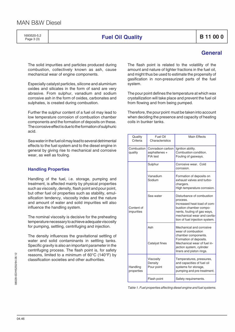
0802
8-0D
/H52
50/9
4.08
.12
MAN B&W Diesel
Quality Fuel Oil Main EffectsCriteria Characteristics
Combustion Conradson carbon Ignition ability.quality asphaltenes + Combustion condition.
FIA test Fouling of gasways.
Sulphur Corrosive wear. Coldcorrosion.
Vanadium Formation of deposits onSodium exhaust valves and turbo-
chargers.High temperature corrosion.
Sea water Disturbance of combustionprocess.Increased heat-load of com-
Content of bustion chamber compo-impurities nents, fouling of gas ways,
mechanical wear and cavita-tion of fuel injection system.
Ash Mechanical and corrosivewear of combustionchamber components.Formation of deposits.
Catalyst fines Mechanical wear of fuel in-jection system, cylinderliners and piston rings.
Viscosity Temperatures, pressures,Density and capacities of fuel oil
Handling Pour point systems for storage,properties pumping and pre-treatment.
Flash point Safety requirements.
The solid impurities and particles produced duringcombustion, collectively known as ash, causemechanical wear of engine components.
Especially catalyst particles, silicone and aluminiumoxides and silicates in the form of sand are veryabrasive. From sulphur, vanadium and sodiumcorrosive ash in the form of oxides, carbonates andsulphates, is created during combustion.
Further the sulphur content of a fuel oil may lead tolow temperature corrosion of combustion chambercomponents and the formation of deposits on these.The corrosive effect is due to the formation of sulphuricacid.
Sea water in the fuel oil may lead to several detrimentaleffects to the fuel system and to the diesel engine ingeneral by giving rise to mechanical and corrosivewear, as well as fouling.
Handling Properties
Handling of the fuel, i.e. storage, pumping andtreatment, is affected mainly by physical propertiessuch as viscosity, density, flash point and pour point,but other fuel oil properties such as stability, emul-sification tendency, viscosity index and the natureand amount of water and solid impurities will alsoinfluence the handling system.
The nominal viscosity is decisive for the preheatingtemperature necessary to achieve adequate viscosityfor pumping, settling, centrifuging and injection.
The density influences the gravitational settling ofwater and solid contaminants in settling tanks.Specific gravity is also an important parameter in thecentrifuging process. The flash point is, for safetyreasons, limited to a minimum of 60°C (140°F) byclassification societies and other authorities.
The flash point is related to the volatility of theamount and nature of lighter fractions in the fuel oil,and might thus be used to estimate the propensity ofgasification in non-pressurized parts of the fuelsystem.
The pour point defines the temperature at which waxcrystallization will take place and prevent the fuel oilfrom flowing and from being pumped.
Therefore, the pour point must be taken into accountwhen deciding the presence and capacity of heatingcoils in bunker tanks.
Table 1. Fuel properties affecting diesel engine and fuel systems.
1693520-5.2Page 3 (3) B 11 00 0
04.46
General
Fuel Oil Quality

0802
8-0D
/H52
50/9
4.08
.12
MAN B&W Diesel
B 11 00 0Fuel Oil Cleaning Recommendations
General
Centrifuging
Fuel oils should always be considered as contami-nated upon delivery and should therefore bethoroughly cleaned to remove solids as well as liquidcontaminants before use.
The solid contaminants in the fuel oil are mainly rust,sand, dust and refinery catalysts. Liquid contami-nants are mainly water, i.e. either fresh water or saltwater.
Impurities in the fuel can cause damage to fuelpumps and fuel valves, and can lead to increasedcylinder liner wear and deterioration of the exhaustvalve seats. Also increased fouling of gas ways andturbocharger blades may result from the use ofinadequately cleaned fuel oil. Effective cleaning canonly be ensured by using a centrifuge.
We recommend that the capacity of the installedcentrifuge should, at least, be according to thecentrifuge maker's instructions.
Cleaning of distillate fuel such as ISO 8217 classesDMX to DMB is generally not necessary. But han-dling of a liquid fuel on board ships gives a risk ofcontamination with sea water. Therefore it is a goodidea to centrifuge all fuel on board ships.
Fuel classes DMC to RMH55 require a treatmentwith centrifuge in all cases.
Automatic centrifuges must be used. Fuel typesRMK35 to RMK55 require centrifuges capable tohandle up to 1010 kg/m3 density.
To obtain optimum cleaning it is of the utmost impor-tance that the centrifuge is operated with a fuel oilviscosity as low as possible, i.e. that the highestpossible temperature is maintained in the centrifugeoil preheater.
Supplementary Equipment
Experience proves that if the centrifugal installationis dimensioned and installed correctly – and oper-ated correctly according to the supplier's instructions– this is a sufficient way of cleaning the fuel.
All supplementary equipment, such as the 10 mµnominal filter, will have a positive effect and maycontribute to longer intervals between overhauls.Also, supplementary equipment will reduce the op-eration costs.
This equipment can give difficulties if incorrectlyinstalled, However if correctly installed and operatedcan with some fuels give benefits in lower wear andsludge formation.
1655267-1.3Page 1 (1)
99.33

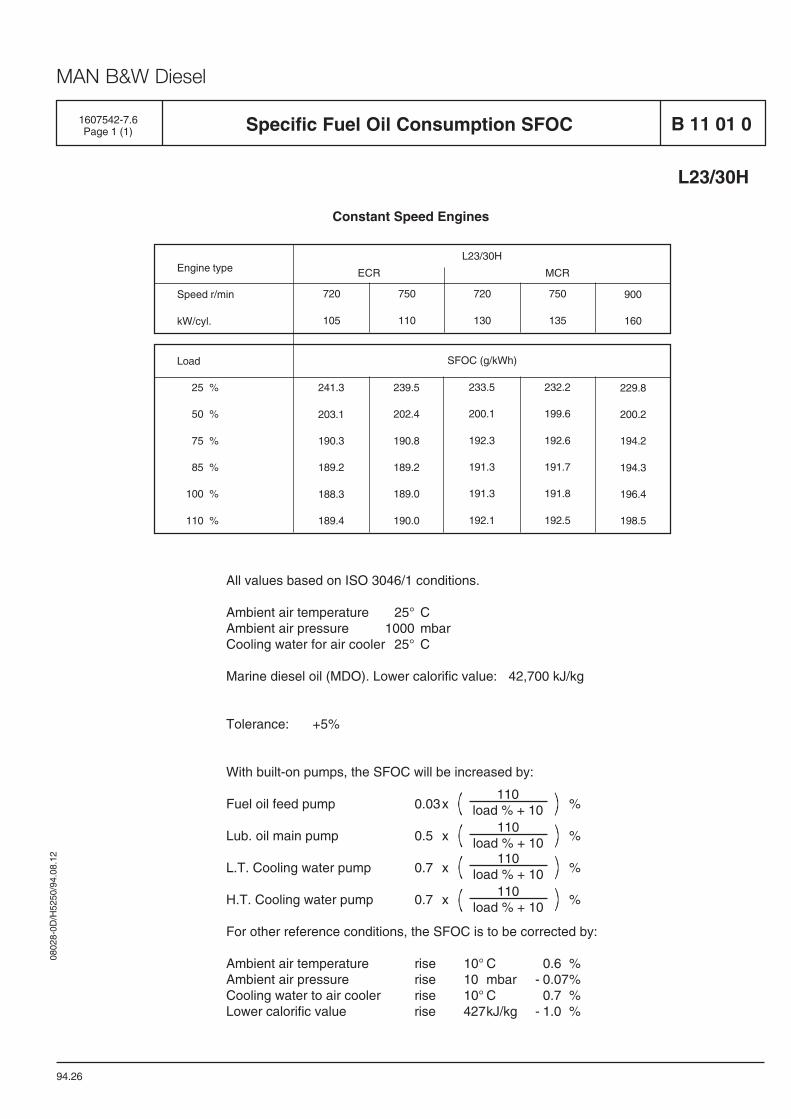
0802
8-0D
/H52
50/9
4.08
.12
MAN B&W Diesel
1607542-7.6Page 1 (1) B 11 01 0Specific Fuel Oil Consumption SFOC
L23/30H
94.26
Constant Speed Engines
All values based on ISO 3046/1 conditions.
Ambient air temperature 25° CAmbient air pressure 1000 mbarCooling water for air cooler 25° C
Marine diesel oil (MDO). Lower calorific value: 42,700 kJ/kg
Tolerance: +5%
With built-on pumps, the SFOC will be increased by:
Fuel oil feed pump 0.03x %
Lub. oil main pump 0.5 x %
L.T. Cooling water pump 0.7 x %
H.T. Cooling water pump 0.7 x %
For other reference conditions, the SFOC is to be corrected by:
Ambient air temperature rise 10° C 0.6 %Ambient air pressure rise 10 mbar - 0.07%Cooling water to air cooler rise 10° C 0.7 %Lower calorific value rise 427kJ/kg - 1.0 %
Engine type
Speed r/min
kW/cyl.
Load
25 %
50 %
75 %
85 %
100 %
110 %
232.2
199.6
192.6
191.7
191.8
192.5
239.5
202.4
190.8
189.2
189.0
190.0
241.3
203.1
190.3
189.2
188.3
189.4
233.5
200.1
192.3
191.3
191.3
192.1
229.8
200.2
194.2
194.3
196.4
198.5
SFOC (g/kWh)
720
105
750
110
720
130
750
135
900
160
L23/30H
ECR MCR
110load % + 10
110load % + 10
110load % + 10
110load % + 10


Lubrication Oil System
B 12

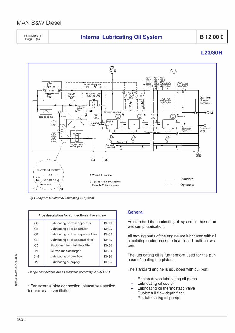
0802
8-0D
/H52
50/9
4.08
.12
MAN B&W Diesel
1613429-7.6Page 1 (4) Internal Lubricating Oil System B 12 00 0
L23/30H
05.34
Fig 1 Diagram for internal lubricating oil system.
Flange connections are as standard according to DIN 2501
Pipe description for connection at the engine
DN25
DN25
DN65
DN65
DN20
DN50
DN50
DN25
Lubricating oil from separator
Lubricating oil to separator
Lubricating oil from separate filter
Lubricating oil to separate filter
Back-flush from full-flow filter
Oil vapour discharge*
Lubricating oil overflow
Lubricating oil supply
C3
C4
C7
C8
C9
C13
C15
C16
* For external pipe connection, please see sectionfor crankcase ventilation.
General
As standard the lubricating oil system is based onwet sump lubrication.
All moving parts of the engine are lubricated with oilcirculating under pressure in a closed built-on sys-tem.
The lubricating oil is furthermore used for the pur-pose of cooling the pistons.
The standard engine is equipped with built-on:
– Engine driven lubricating oil pump– Lubricating oil cooler– Lubricating oil thermostatic valve– Duplex full-flow depth filter– Pre-lubricating oil pump
0802
8-0D
/H52
50/9
4.08
.12
MAN B&W Diesel
05.34
1613429-7.6Page 2 (4)Internal Lubricating Oil SystemB 12 00 0
L23/30H
Oil Quantities
The approximate quantities of oil necessary for anew engine, before starting up are given in the table,see "B 12 01 1 Lubricating Oil in Base Frame" (max.litre H3)
If there are connected external, full-flow filters etc.,the quantity of oil in the external piping must also betaken into account.
Max. velocity recommendations for external lubrica-ting oil pipes:
– Pump suction side 1.0 - 1.5 m/s– Pump discharge side 1.5 - 2.0 m/s
Lubricating Oil Consumption
The lubricating oil consumption is 0.6 - 1.0 g/kWh,see "Specific Lubricating Oil Consumption - SLOC,B 12 15 0 / 504.07"
It should, however, be observed that during therunning in period the lubricating oil consumption mayexceed the values stated.
Quality of Oil
Only HD lubricating oil (Detergent Lubricating Oil)should be used, characteristic stated in "LubricatingOil Specification B 12 15 0".
System Flow
The lubricating oil pump draws oil from the oil sumpand presses the oil through the cooler and filter to themain lubricating oil pipe, from where the oil is distri-buted to the individual lubricating points. From thelubricating points the oil returns by gravity to the oilsump.
The main groups of components to be lubricated are:
1 – Turbocharger
2 – Main bearings, big-end bearing etc.
3 – Camshaft drive
4 – Governor drive
5 – Rocker arms
6 – Camshaft
1) For priming and during operation, the turbo-charger is connected to the lubricating oilcircuit of the engine, the oil serves for bearinglubrication and also for dissipation of heat.
The inlet line to the turbocharger is equippedwith an orifice in order to adjust the oil flow anda non-return valve to prevent draining duringstand-still.
The non-return valve has back-pressure func-tion requiring a pressure slightly above thepriming pressure to open in normal flow direc-tion. In this way overflooding of the turbo-charger is prevented during stand-still periods,where the pre-lubricating pump is running.
2) Lubricating oil for the main bearings is sup-plied through holes drilled in the engine frame.From the main bearings it passes throughbores in the crankshaft to the connecting rodbig-end bearings.
The connecting rods have bored channels forsupply of oil from the big-end bearings to thesmall-end bearings, which has an inner cir-cumferential groove, and a pocket for distribu-tion of oil in the bush itself and for supply of oilto the pin bosses and the piston cooling throughholes and channels in the piston pin.
From the front main bearings channels arebored in the crankshaft for lubricating of thepump drive.
0802
8-0D
/H52
50/9
4.08
.12
MAN B&W Diesel
B 12 00 0
05.34
Internal Lubricating Oil System
L23/30H
1613429-7.6Page 3 (4)
3) The lubricating oil pipes, for the camshaft drivegear wheels, are equipped with nozzles whichare adjusted to apply the oil at the points wherethe gear wheels are in mesh.
4) The lubricating oil pipe, and the gear wheelsfor the governor drive are adjusted to apply theoil at the points where the gear wheels are inmesh.
5) The lubricating oil to the rocker arms is ledthrough pipes to each cylinder head. It continu-ous through bores in the cylinder head androcker arm to the movable parts to be lubri-cated at rocker arms and valve bridge. Further,lubricating oil is led to the movable parts inneed of lubrication.
6) Through a bore in the frame lubricating oil isled to the first camshaft bearing and throughbores in the camshaft from where it is distrib-uted to the other camshaft bearings.
Lubricating Oil Pump
The lubricating oil pump, which is of the gear wheeltype, is mounted on the front end of the engine andis driven by means of the crankshaft through acoupling. The oil pressure is controlled by an adjust-able spring- loaded relief valve built-on the oil pump.
Lubricating Oil Cooler
As standard the lubricating oil cooler is of the platetype. The cooler is mounted to the front end of thebase frame.
Thermostatic Valve
The thermostatic valve is a fully automatic three-wayvalve with thermostatic elements set of fixed tem-perature.
Built-on Full-flow Depth Filter
The built-on lubricating oil filter is of the duplex papercartridge type. It is a depth filter with a nominelfineness of 10-15 microns, and a safety filter with afineness of 60 microns.
Pre-lubricating
As standard the engine is equipped with an electric-driven pre-lubricating pump mounted parallel to themain pump. The pump must be arranged for auto-matic operation, ensuring stand-still of the pre-lubri-cating pump when the engine is running, and runningdur-ing engine stand-still in stand-by position.
Running period of the pre-lubricating pump is prefer-ably to be continuous. If intermittent running is requi-red for energy saving purpose, the timing equipmentshould be set for shortest possible intervals, say 2minutes of running, 10 minures of stand-still, etc.Further, it is recommended that the pre-lubricatingpump is connected to the emergency switch boardthus securing that the engine is not started withoutpre-lubrication.
Draining of the Oil Sump
It is recommended to use the separator suction pipefor draining of the lubricating oil sump.
Crankcase Ventilation
The crankcase ventilation is not to be directly con-nected with any other piping system. It is preferablethat the crankcase ventilation pipe from each engineis led independently to the open air. The outlet is tobe fitted with corrosion resistant flame screen sepa-rately for each engine.
However, if a manifold arrangements is used, itsarrangements are to be as follows:
1) The vent pipe from each engine is to runindepently to the manifold, and be fitted withcorrosion resistant flame screen within themanifold.
0802
8-0D
/H52
50/9
4.08
.12
MAN B&W Diesel
1613429-7.6Page 4 (4)Internal Lubricating Oil SystemB 12 00 0
05.34
L23/30H
2) The manifold is to be located as high aspracticable so as to allow substantial length ofpiping separating the crankcase.
3) The manifold is to be vented to the open air,such that the vent outlet is fitted with corrosionresistant flame screen, and the clear openarea of the vent outlet is not less than theaggregate area of the individual crankcasevent pipes entering the manifold.
4) The manifold is to be provided with drainagearrangement.
The ventilation pipe should be designed to eliminatethe risk of water condensation in the pipe flowingback into the engine and should end in the open air:
– The connection between engine (C13) and theventilation pipe must be flexible.
– The ventilation pipe should be continuouslyinclined (min. 5 degrees).
– A continuous drain has to be installed near theengine. The drain must not be lead back to theengine.
– Dimension of the flexible connection DN50.– Dimension of the ventilation pipe after the
flexible connection min. DN65.
Optionals
Besides the standard components, the followingoptionals can be built-on:
– Level switch for low/high level in oil sump(LAL/LAH 28)
– Centrifugal by-pass filter(standard for stationary engines)
– Hand wing pump
Pressure differential transmitting– PDT 21-22 Lubricating oil inlet across filter
Temperature alarm high– TAH 20 Lubricating oil inlet before cooler
Pressure transmitting– PT 22 Lubricating oil inlet after cooler
Temperature element– TE 20 Lubricating oil inlet before cooler
Temperature element– TE 22 Lubricating oil inlet after cooler
Temperature element– TE 29 Lubricating oil inlet main bearings
Branches for:
– External fine filter– External full/flow filter
Branches for separator is standard.
Data
For heat dissipation and pump capacities, see D 1005 0 "List of Capacities".
Operation levels for temperature and pressure arestated in B 19 00 0 "Operating Data and Set Points.
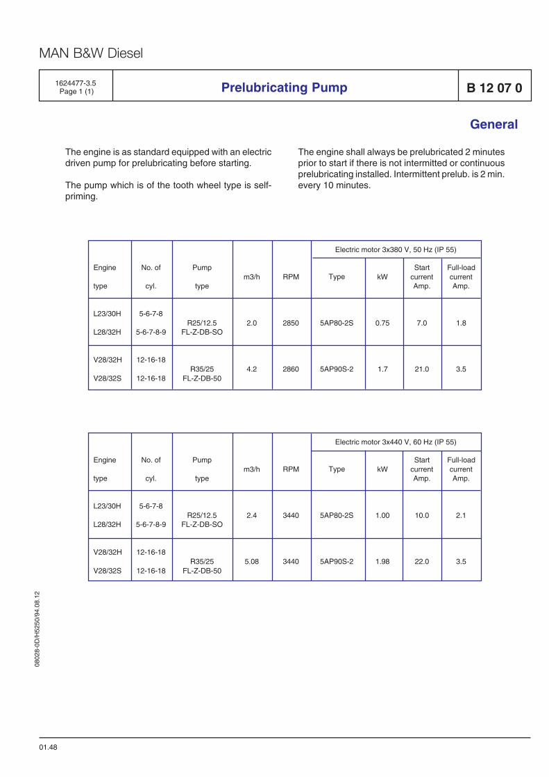
0802
8-0D
/H52
50/9
4.08
.12
MAN B&W Diesel
B 12 07 0Prelubricating Pump1624477-3.5 Page 1 (1)
01.48
General
The engine is as standard equipped with an electricdriven pump for prelubricating before starting.
The pump which is of the tooth wheel type is self-priming.
The engine shall always be prelubricated 2 minutesprior to start if there is not intermitted or continuousprelubricating installed. Intermittent prelub. is 2 min.every 10 minutes.
Full-loadcurrentAmp.
1.8
3.5
m3/h
2.0
4.2
RPM
2850
2860
kW
0.75
1.7
StartcurrentAmp.
7.0
21.0
Type
5AP80-2S
5AP90S-2
Pump
type
R25/12.5FL-Z-DB-SO
R35/25FL-Z-DB-50
No. of
cyl.
5-6-7-8
5-6-7-8-9
12-16-18
12-16-18
Engine
type
L23/30H
L28/32H
V28/32H
V28/32S
Electric motor 3x380 V, 50 Hz (IP 55)
Full-loadcurrentAmp.
2.1
3.5
m3/h
2.4
5.08
RPM
3440
3440
kW
1.00
1.98
StartcurrentAmp.
10.0
22.0
Type
5AP80-2S
5AP90S-2
Pump
type
R25/12.5FL-Z-DB-SO
R35/25FL-Z-DB-50
No. of
cyl.
5-6-7-8
5-6-7-8-9
12-16-18
12-16-18
Engine
type
L23/30H
L28/32H
V28/32H
V28/32S
Electric motor 3x440 V, 60 Hz (IP 55)

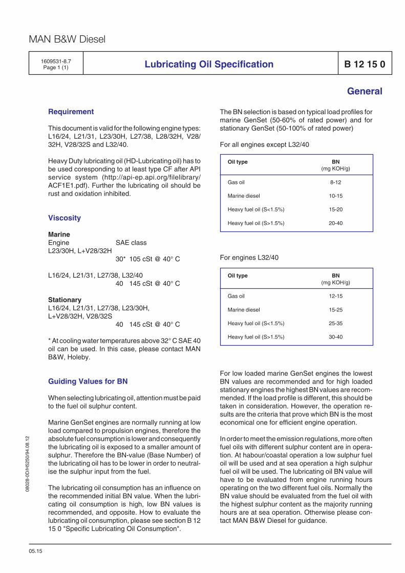
0802
8-0D
/H52
50/9
4.08
.12
MAN B&W Diesel
1609531-8.7Page 1 (1) B 12 15 0Lubricating Oil Specification
General
05.15
Requirement
This document is valid for the following engine types:L16/24, L21/31, L23/30H, L27/38, L28/32H, V28/32H, V28/32S and L32/40.
Heavy Duty lubricating oil (HD-Lubricating oil) has tobe used coresponding to at least type CF after APIservice system (http://api-ep.api.org/filelibrary/ACF1E1.pdf). Further the lubricating oil should berust and oxidation inhibited.
Viscosity
MarineEngine SAE classL23/30H, L+V28/32H
30* 105 cSt @ 40° C
L16/24, L21/31, L27/38, L32/4040 145 cSt @ 40° C
StationaryL16/24, L21/31, L27/38, L23/30H,L+V28/32H, V28/32S
40 145 cSt @ 40° C
* At cooling water temperatures above 32° C SAE 40oil can be used. In this case, please contact MANB&W, Holeby.
Guiding Values for BN
When selecting lubricating oil, attention must be paidto the fuel oil sulphur content.
Marine GenSet engines are normally running at lowload compared to propulsion engines, therefore theabsolute fuel consumption is lower and consequentlythe lubricating oil is exposed to a smaller amount ofsulphur. Therefore the BN-value (Base Number) ofthe lubricating oil has to be lower in order to neutral-ise the sulphur input from the fuel.
The lubricating oil consumption has an influence onthe recommended initial BN value. When the lubri-cating oil consumption is high, low BN values isrecommended, and opposite. How to evaluate thelubricating oil consumption, please see section B 1215 0 "Specific Lubricating Oil Consumption".
The BN selection is based on typical load profiles formarine GenSet (50-60% of rated power) and forstationary GenSet (50-100% of rated power)
For all engines except L32/40
Oil type BN(mg KOH/g)
Gas oil 8-12
Marine diesel 10-15
Heavy fuel oil (S<1.5%) 15-20
Heavy fuel oil (S>1.5%) 20-40
For engines L32/40
Oil type BN(mg KOH/g)
Gas oil 12-15
Marine diesel 15-25
Heavy fuel oil (S<1.5%) 25-35
Heavy fuel oil (S>1.5%) 30-40
For low loaded marine GenSet engines the lowestBN values are recommended and for high loadedstationary engines the highest BN values are recom-mended. If the load profile is different, this should betaken in consideration. However, the operation re-sults are the criteria that prove which BN is the mosteconomical one for efficient engine operation.
In order to meet the emission regulations, more oftenfuel oils with different sulphur content are in opera-tion. At habour/coastal operation a low sulphur fueloil will be used and at sea operation a high sulphurfuel oil will be used. The lubricating oil BN value willhave to be evaluated from engine running hoursoperating on the two different fuel oils. Normally theBN value should be evaluated from the fuel oil withthe highest sulphur content as the majority runninghours are at sea operation. Otherwise please con-tact MAN B&W Diesel for guidance.

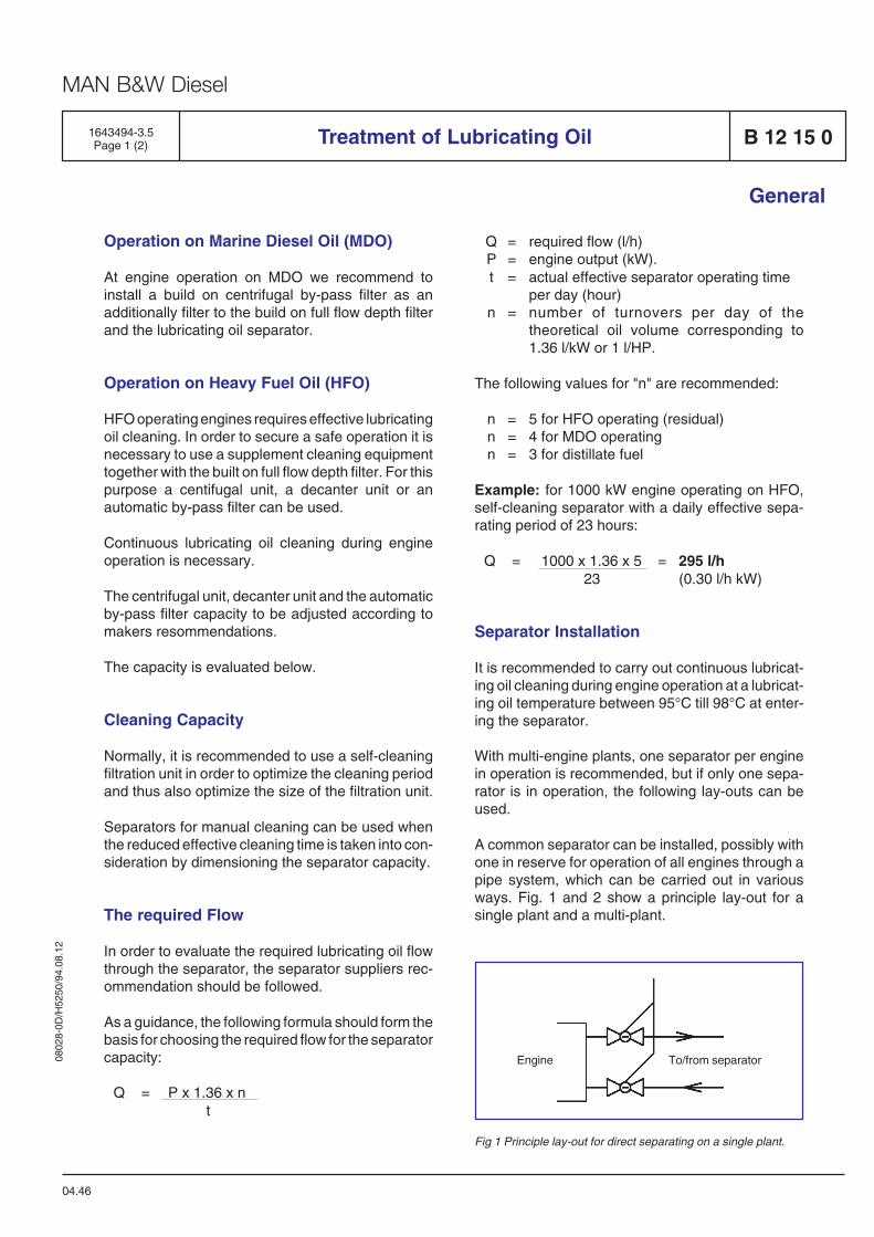
0802
8-0D
/H52
50/9
4.08
.12
MAN B&W Diesel
Operation on Marine Diesel Oil (MDO)
At engine operation on MDO we recommend toinstall a build on centrifugal by-pass filter as anadditionally filter to the build on full flow depth filterand the lubricating oil separator.
Operation on Heavy Fuel Oil (HFO)
HFO operating engines requires effective lubricatingoil cleaning. In order to secure a safe operation it isnecessary to use a supplement cleaning equipmenttogether with the built on full flow depth filter. For thispurpose a centifugal unit, a decanter unit or anautomatic by-pass filter can be used.
Continuous lubricating oil cleaning during engineoperation is necessary.
The centrifugal unit, decanter unit and the automaticby-pass filter capacity to be adjusted according tomakers resommendations.
The capacity is evaluated below.
Cleaning Capacity
Normally, it is recommended to use a self-cleaningfiltration unit in order to optimize the cleaning periodand thus also optimize the size of the filtration unit.
Separators for manual cleaning can be used whenthe reduced effective cleaning time is taken into con-sideration by dimensioning the separator capacity.
The required Flow
In order to evaluate the required lubricating oil flowthrough the separator, the separator suppliers rec-ommendation should be followed.
As a guidance, the following formula should form thebasis for choosing the required flow for the separatorcapacity:
Q = P x 1.36 x nt
1643494-3.5Page 1 (2) Treatment of Lubricating Oil B 12 15 0
General
04.46
Q = required flow (l/h)P = engine output (kW).t = actual effective separator operating time
per day (hour)n = number of turnovers per day of the
theoretical oil volume corresponding to1.36 l/kW or 1 l/HP.
The following values for "n" are recommended:
n = 5 for HFO operating (residual)n = 4 for MDO operatingn = 3 for distillate fuel
Example: for 1000 kW engine operating on HFO,self-cleaning separator with a daily effective sepa-rating period of 23 hours:
Q = 1000 x 1.36 x 5 = 295 l/h23 (0.30 l/h kW)
Separator Installation
It is recommended to carry out continuous lubricat-ing oil cleaning during engine operation at a lubricat-ing oil temperature between 95°C till 98°C at enter-ing the separator.
With multi-engine plants, one separator per enginein operation is recommended, but if only one sepa-rator is in operation, the following lay-outs can beused.
A common separator can be installed, possibly withone in reserve for operation of all engines through apipe system, which can be carried out in variousways. Fig. 1 and 2 show a principle lay-out for asingle plant and a multi-plant.
To/from separatorEngine
Fig 1 Principle lay-out for direct separating on a single plant.
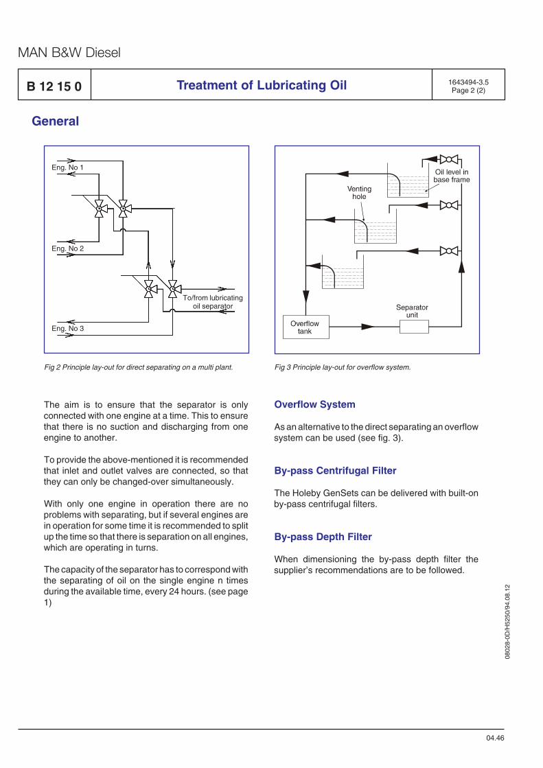
0802
8-0D
/H52
50/9
4.08
.12
MAN B&W Diesel
General
Eng. No 2
Eng. No 1
To/from lubricatingoil separator
Eng. No 3
Fig 2 Principle lay-out for direct separating on a multi plant. Fig 3 Principle lay-out for overflow system.
04.46
B 12 15 0 Treatment of Lubricating Oil 1643494-3.5Page 2 (2)
The aim is to ensure that the separator is onlyconnected with one engine at a time. This to ensurethat there is no suction and discharging from oneengine to another.
To provide the above-mentioned it is recommendedthat inlet and outlet valves are connected, so thatthey can only be changed-over simultaneously.
With only one engine in operation there are noproblems with separating, but if several engines arein operation for some time it is recommended to splitup the time so that there is separation on all engines,which are operating in turns.
The capacity of the separator has to correspond withthe separating of oil on the single engine n timesduring the available time, every 24 hours. (see page1)
Overflow System
As an alternative to the direct separating an overflowsystem can be used (see fig. 3).
By-pass Centrifugal Filter
The Holeby GenSets can be delivered with built-onby-pass centrifugal filters.
By-pass Depth Filter
When dimensioning the by-pass depth filter thesupplier’s recommendations are to be followed.

Cooling Water System
B 13


0802
8-0D
/H52
50/9
4.08
.12
MAN B&W Diesel
1609571-3.4Page 1 (5) Freshwater System Treatment B 13 00 0
General
00.11
Cleaning agents emulsified in water as well asslightly alkaline cleaning agents can be used for thedegreasing process, whereas ready-mixed cleaningagents which involve the risk of fire must obviouslynot be used. For descaling with acid, especiallyproducts based on amino-sulphonic acid, citric acid,and tartaric acid are recommendable, as these acidsare usually obtainable as solid substances, easilysoluble in water, and do not emit poisonous vapours.
The cleaning agents should not be directly admixed,but should be dissolved in water and then added tothe cooling water system.
Normally, cleaning can be executed without anydismantling of the engine. We point out that the watershould be circulated in the engine to achieve the bestpossible result.
As cleaning can cause leaks to become apparent inpoorly assembled joints or partly defective gaskets,inspection should be carried out during the cleaningprocess. The acid content of the system oil shouldalso be checked immediately after cleaning, and 24hours afterwards.
Cooling Water - Inhibitors
The filling-up with cooling water and the admixture ofthe inhibitor is to be carried out directly after thecleaning in order to prevent formation of rust on thecleaned surfaces.
Raw Water
The formation of lime stone on cylinder liners and incylinder heads may reduce the heat transfer, whichwill result in unacceptably high temperatures in thematerial.
Therefore, it is recommended that deionized ordistilled water (for example from the freshwatergenerator) is used as cooling water. However, onaccount of its lack of hardness, this water will berelatively corrosive, and a corrosion inhibitor shouldtherefore always be added.
Protection against Corrosion in FreshwaterCooling System
The engine fresh water must be carefully treated,maintained and monitored so as to avoid corrosionor the formation of deposits which can result ininsufficient heat transfer, it is necessary to treat thecooling water. MAN B&W recommend that this treat-ment is carried out according to the following proce-dure:
– Clean the cooling water system.
– Fill up with deionized or distilled cooling water(for example from the freshwater generator)with corrosion inhibitor added.
– Carry out regular checks of the cooling watersystem and the condition of the cooling water.
Observance of these precautions, and correct ven-ting of the system, will reduce service difficultiescaused by the cooling water to a minimum.
Cleaning of the Cooling Water System
Before starting the inhibition process, any existingdeposits of lime or rust, or any oil sludge, should beremoved in order to improve the heat transfer and toensure uniform protection of the surface by means ofthe inhibitor.
The cleaning should comprise degreasing to removeoil sludge, and descaling with acid afterwards toremove rust and lime deposits.
Ready-mixed cleaning agents, specially made forcleaning the cooling water system, can be obtainedfrom companies specializing in cooling water treat-ment. These companies offer assistance and controlof the treatment in all major ports. A number of thesecompanies are mentioned on the enclosed list. Wepoint out that the directions given by them should beclosely followed. It is of particular importance to flushthe system completely after cleaning.
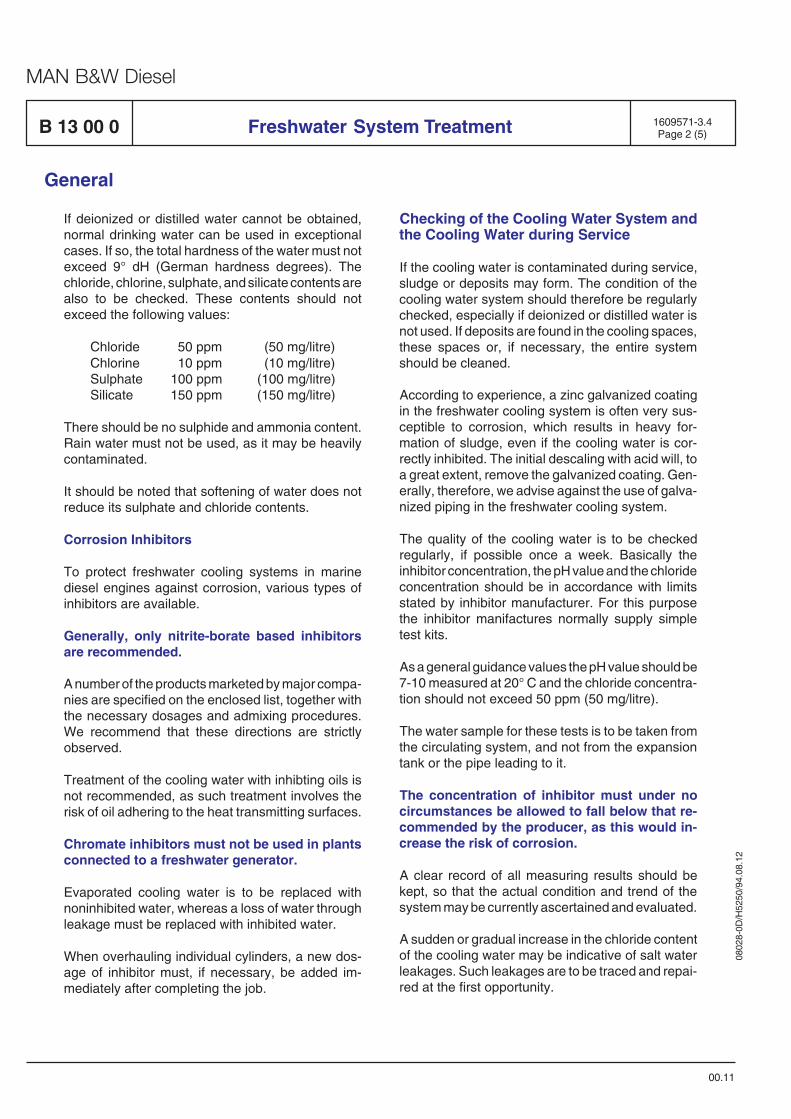
0802
8-0D
/H52
50/9
4.08
.12
MAN B&W Diesel
B 13 00 0 1609571-3.4Page 2 (5)
General
00.11
If deionized or distilled water cannot be obtained,normal drinking water can be used in exceptionalcases. If so, the total hardness of the water must notexceed 9° dH (German hardness degrees). Thechloride, chlorine, sulphate, and silicate contents arealso to be checked. These contents should notexceed the following values:
Chloride 50 ppm (50 mg/litre)Chlorine 10 ppm (10 mg/litre)Sulphate 100 ppm (100 mg/litre)Silicate 150 ppm (150 mg/litre)
There should be no sulphide and ammonia content.Rain water must not be used, as it may be heavilycontaminated.
It should be noted that softening of water does notreduce its sulphate and chloride contents.
Corrosion Inhibitors
To protect freshwater cooling systems in marinediesel engines against corrosion, various types ofinhibitors are available.
Generally, only nitrite-borate based inhibitorsare recommended.
A number of the products marketed by major compa-nies are specified on the enclosed list, together withthe necessary dosages and admixing procedures.We recommend that these directions are strictlyobserved.
Treatment of the cooling water with inhibting oils isnot recommended, as such treatment involves therisk of oil adhering to the heat transmitting surfaces.
Chromate inhibitors must not be used in plantsconnected to a freshwater generator.
Evaporated cooling water is to be replaced withnoninhibited water, whereas a loss of water throughleakage must be replaced with inhibited water.
When overhauling individual cylinders, a new dos-age of inhibitor must, if necessary, be added im-mediately after completing the job.
Checking of the Cooling Water System andthe Cooling Water during Service
If the cooling water is contaminated during service,sludge or deposits may form. The condition of thecooling water system should therefore be regularlychecked, especially if deionized or distilled water isnot used. If deposits are found in the cooling spaces,these spaces or, if necessary, the entire systemshould be cleaned.
According to experience, a zinc galvanized coatingin the freshwater cooling system is often very sus-ceptible to corrosion, which results in heavy for-mation of sludge, even if the cooling water is cor-rectly inhibited. The initial descaling with acid will, toa great extent, remove the galvanized coating. Gen-erally, therefore, we advise against the use of galva-nized piping in the freshwater cooling system.
The quality of the cooling water is to be checkedregularly, if possible once a week. Basically theinhibitor concentration, the pH value and the chlorideconcentration should be in accordance with limitsstated by inhibitor manufacturer. For this purposethe inhibitor manifactures normally supply simpletest kits.
As a general guidance values the pH value should be7-10 measured at 20° C and the chloride concentra-tion should not exceed 50 ppm (50 mg/litre).
The water sample for these tests is to be taken fromthe circulating system, and not from the expansiontank or the pipe leading to it.
The concentration of inhibitor must under nocircumstances be allowed to fall below that re-commended by the producer, as this would in-crease the risk of corrosion.
A clear record of all measuring results should bekept, so that the actual condition and trend of thesystem may be currently ascertained and evaluated.
A sudden or gradual increase in the chloride contentof the cooling water may be indicative of salt waterleakages. Such leakages are to be traced and repai-red at the first opportunity.
Freshwater System Treatment
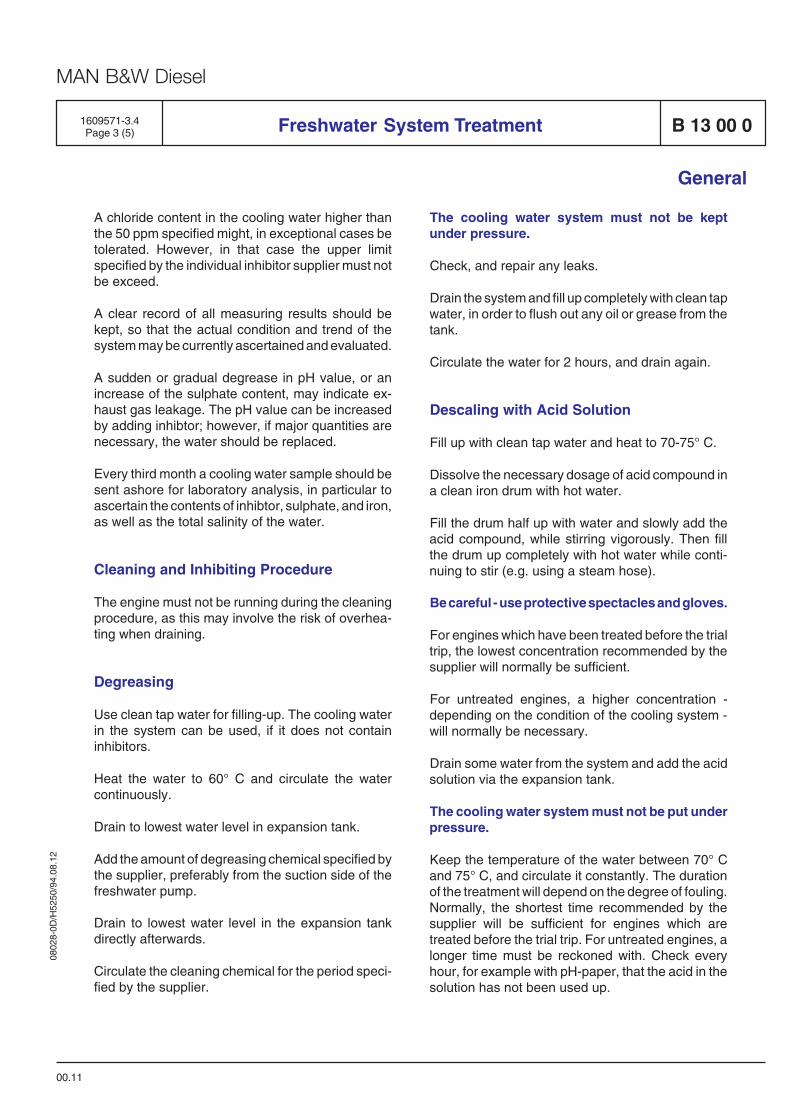
0802
8-0D
/H52
50/9
4.08
.12
MAN B&W Diesel
B 13 00 0Freshwater System Treatment1609571-3.4Page 3 (5)
General
00.11
A chloride content in the cooling water higher thanthe 50 ppm specified might, in exceptional cases betolerated. However, in that case the upper limitspecified by the individual inhibitor supplier must notbe exceed.
A clear record of all measuring results should bekept, so that the actual condition and trend of thesystem may be currently ascertained and evaluated.
A sudden or gradual degrease in pH value, or anincrease of the sulphate content, may indicate ex-haust gas leakage. The pH value can be increasedby adding inhibtor; however, if major quantities arenecessary, the water should be replaced.
Every third month a cooling water sample should besent ashore for laboratory analysis, in particular toascertain the contents of inhibtor, sulphate, and iron,as well as the total salinity of the water.
Cleaning and Inhibiting Procedure
The engine must not be running during the cleaningprocedure, as this may involve the risk of overhea-ting when draining.
Degreasing
Use clean tap water for filling-up. The cooling waterin the system can be used, if it does not containinhibitors.
Heat the water to 60° C and circulate the watercontinuously.
Drain to lowest water level in expansion tank.
Add the amount of degreasing chemical specified bythe supplier, preferably from the suction side of thefreshwater pump.
Drain to lowest water level in the expansion tankdirectly afterwards.
Circulate the cleaning chemical for the period speci-fied by the supplier.
The cooling water system must not be keptunder pressure.
Check, and repair any leaks.
Drain the system and fill up completely with clean tapwater, in order to flush out any oil or grease from thetank.
Circulate the water for 2 hours, and drain again.
Descaling with Acid Solution
Fill up with clean tap water and heat to 70-75° C.
Dissolve the necessary dosage of acid compound ina clean iron drum with hot water.
Fill the drum half up with water and slowly add theacid compound, while stirring vigorously. Then fillthe drum up completely with hot water while conti-nuing to stir (e.g. using a steam hose).
Be careful - use protective spectacles and gloves.
For engines which have been treated before the trialtrip, the lowest concentration recommended by thesupplier will normally be sufficient.
For untreated engines, a higher concentration -depending on the condition of the cooling system -will normally be necessary.
Drain some water from the system and add the acidsolution via the expansion tank.
The cooling water system must not be put underpressure.
Keep the temperature of the water between 70° Cand 75° C, and circulate it constantly. The durationof the treatment will depend on the degree of fouling.Normally, the shortest time recommended by thesupplier will be sufficient for engines which aretreated before the trial trip. For untreated engines, alonger time must be reckoned with. Check everyhour, for example with pH-paper, that the acid in thesolution has not been used up.
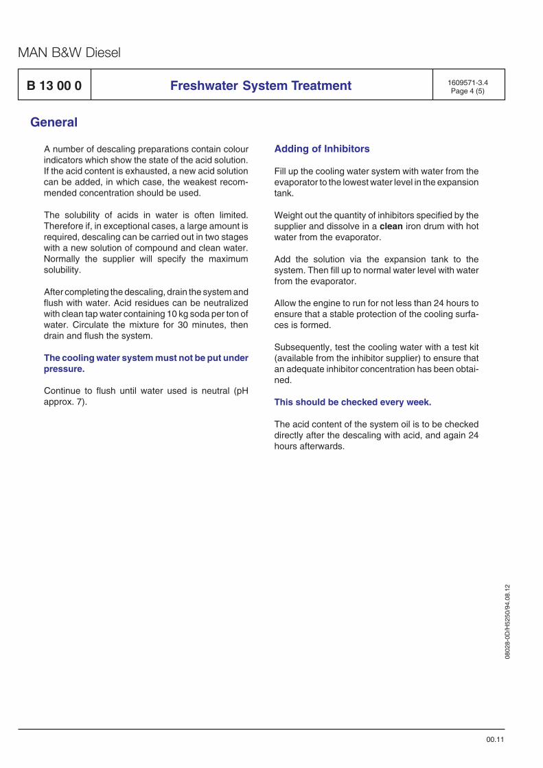
0802
8-0D
/H52
50/9
4.08
.12
MAN B&W Diesel
A number of descaling preparations contain colourindicators which show the state of the acid solution.If the acid content is exhausted, a new acid solutioncan be added, in which case, the weakest recom-mended concentration should be used.
The solubility of acids in water is often limited.Therefore if, in exceptional cases, a large amount isrequired, descaling can be carried out in two stageswith a new solution of compound and clean water.Normally the supplier will specify the maximumsolubility.
After completing the descaling, drain the system andflush with water. Acid residues can be neutralizedwith clean tap water containing 10 kg soda per ton ofwater. Circulate the mixture for 30 minutes, thendrain and flush the system.
The cooling water system must not be put underpressure.
Continue to flush until water used is neutral (pHapprox. 7).
B 13 00 0 1609571-3.4Page 4 (5)
General
00.11
Freshwater System Treatment
Adding of Inhibitors
Fill up the cooling water system with water from theevaporator to the lowest water level in the expansiontank.
Weight out the quantity of inhibitors specified by thesupplier and dissolve in a clean iron drum with hotwater from the evaporator.
Add the solution via the expansion tank to thesystem. Then fill up to normal water level with waterfrom the evaporator.
Allow the engine to run for not less than 24 hours toensure that a stable protection of the cooling surfa-ces is formed.
Subsequently, test the cooling water with a test kit(available from the inhibitor supplier) to ensure thatan adequate inhibitor concentration has been obtai-ned.
This should be checked every week.
The acid content of the system oil is to be checkeddirectly after the descaling with acid, and again 24hours afterwards.
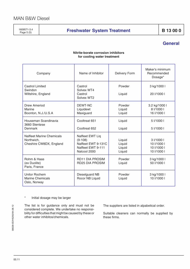
0802
8-0D
/H52
50/9
4.08
.12
MAN B&W Diesel
1609571-3.4Page 5 (5) Freshwater System Treatment B 13 00 0
General
00.11
Company
Castrol LimitedSwindonWiltshire, England
Drew AmeriodMarineBoonton, N.J./U.S.A
Houseman Scandinavia3660 StenløseDenmark
Nalfleet Marine ChemicalsNorthwich,Cheshire CW8DX, England
Rohm & Haas(ex Duolite)Paris, France
Unitor RochemMarine ChemicalsOslo, Norway
CastrolSolvex WT4CastrolSolvex WT2
DEWT-NCLiquidewtMaxiguard
Cooltreat 651
Cooltreat 652
Nalfleet EWT Liq(9-108)Nalfleet EWT 9-131CNalfleet EWT 9-111Nalcool 2000
RD11 DIA PROSIMRD25 DIA PROSIM
Dieselguard NBRocor NB Liquid
Powder
Liquid
PowderLiquidLiquid
Liquid
Liquid
LiquidLiquidLiquidLiquid
PowderLiquid
PowderLiquid
3 kg/1000 l
20 l/1000 l
3.2 kg/1000 l8 l/1000 l
16 l/1000 l
5 l/1000 l
5 l/1000 l
3 l/1000 l10 l/1000 l10 l/1000 l10 l/1000 l
3 kg/1000 l50 l/1000 l
3 kg/1000 l10 l/1000 l
Name of Inhibitor Delivery Form
* Initial dosage may be larger
The list is for guidance only and must not beconsidered complete. We undertake no responsi-bility for difficulties that might be caused by these orother water inhibitos/chemicals.
The suppliers are listed in alpabetical order.
Suitable cleaners can normally be supplied bythese firms.
Maker's minimumRecommended
Dosage*
Nitrite-borate corrosion inhibitorsfor cooling water treatment

0802
8-0D
/H52
50/9
4.08
.12
MAN B&W Diesel
Internal Cooling Water System B 13 00 0
Internal Cooling Water System
The engine's cooling water system comprises a lowtemperature (LT) circuit and a high temperature (HT)circuit.
Low Temperature Cooling Water System
The LT cooling water system includes charge aircooling, lubricating oil cooling and alternator coolingif the latter is water-cooled. The LT system is de-signed for freshwater (FW) as cooling medium.Seawater (SW) can be used as optional.
In order to prevent a too high charge air temperature,the design freshwater temperature in the LT systemshould not be too high Max. 36°C is a convenientchoice compared to the design for seawater tem-perature of maximum 32°C.
Regarding the lubricating oil cooler, the inlet tempe-rature of the LT cooling water should not be below10°C.
High Temperature Cooling Water System
The high temperature cooling water is used for thecooling of cylinder liners and cylinder heads.
An engine outlet temperature of 80°C ensures aperfect combustion in the entire load area whenrunning on Heavy Fuel Oil (HFO), i.e. this tempe-rature limits the thermal loads in the high-load area,and hot corrosion in the combustion area is avoided.
In the low-load area, the temperature is sufficientlyhigh to secure a perfect combustion and at the sametime cold corrosion is avoided; the latter is also thereason why the engine, in stand-by position andwhen starting on HFO, should be preheated with amedium cooling water temperature of at least 60°C- either by means of cooling water from runningengines or by means of a separate preheatingsystem.
System Lay-Out
MAN B&W Holeby's standard for the internal coolingwater system is shown on Basis Diagram 2. Thesystem has been constructed with a view to fullintegration into the external system.
Temperature regulation in the HT and LT systemstakes place in the external system where also pumpsand freshwater heat exchangers are situated. Thismeans that these components can be common forpropulsion engine(s) and GenSets. The separationof HT and LT circuits means that the cooling mediumfor the LT system can be either SW or FW, so thatBasis System 2 can match a conventional as well asa central cooling water system.
To be able to match every kind of external systems,the internal system can as optional be arranged withtwo separate circuits or as a single circuit with orwithout a built-on pump and a thermostatic valve inthe HT-circuit, so that engine cooling can be inte-grated fully or partly into the external system, or canbe constructed as a stand-alone unit.
Different internal basis system layouts for theseapplications are shown on the following pages.
HT-Circulating Pumps
The circulating pump which is of the centrifugal typeis mounted on the front cover of the engine and isdriven by the crankshaft through a resilient geartransmission.
Technical data : See "list of capacities" D 10 05 0and B 13 18 1-2.
Thermostatic Valve
The termostatic valve is a fully automatic three-wayvalve with thermostatic elements set at fixed tem-perature.
Technical data: See B 13 15 1.
95.09
1613439-3.1Page 1 (2)
General
0802
8-0D
/H52
50/9
4.08
.12
MAN B&W Diesel
B 13 00 0
Preheating Arrangement
As an optional the engine can be equipped with abuilt-on preheating arrangement in the HT-circuitincluding a thermostatic controlled el-heating ele-ment and safety valve.
The system is based on thermo-syphon circulation.
For further information see B 13 23 1.
Internal Cooling Water System
95.09
1613439-3.1Page 2 (2)
General
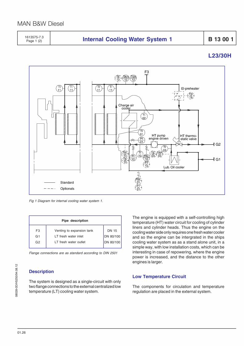
0802
8-0D
/H52
50/9
4.08
.12
MAN B&W Diesel
Internal Cooling Water System 1 B 13 00 1
L23/30H
1613575-7.3Page 1 (2)
01.26
Fig 1 Diagram for internal cooling water system 1.
Description
The system is designed as a single-circuit with onlytwo flange connections to the external centralized lowtemperature (LT) cooling water system.
Flange connections are as standard according to DIN 2501
Venting to expansion tank
LT fresh water inlet
LT fresh water outlet
Pipe description
DN 15
DN 80/100
DN 80/100
F3
G1
G2
The engine is equipped with a self-controlling hightemperature (HT) water circuit for cooling of cylinderliners and cylinder heads. Thus the engine on thecooling water side only requires one fresh water coolerand so the engine can be intergrated in the shipscooling water system as as a stand alone unit, in asimple way, with low installation costs, which can beinteresting in case of repowering, where the enginepower is increased, and the distance to the otherengines is larger.
Low Temperature Circuit
The components for circulation and temperatureregulation are placed in the external system.

0802
8-0D
/H52
50/9
4.08
.12
MAN B&W Diesel
B 13 00 1
The charge air cooler and the lubricating oil cooler aresiuated parallelly in order to have the lowest possiblecooling water inlet temperature for both coolers.
The HT-circuit is cooled by adjustment of water fromthe LT-circuit, taken from the lubricating oil cooleroutlet. Thus the amount of cooling water through thecooling system is always adjusted to the engine load.
High Temperature Circuit
The built-on engine driven HT-circulating pump of thecentrifugal type, pumps water through a distributingpipe to bottom of the cooling water space betweenthe liner and the frame of each cylinder unit. The wateris led out through bores in the top of the frame via thecooling water guide jacket to the bore cooled cylinderhead for cooling of this and the valve seats.
From the cylinder heads the water is led through acommon outlet pipe to the thermostatic valve, anddepending on the engine load, a smaller or largeramount of the water will be led to the external systemor be re-circulated.
Internal Cooling Water System 1
L23/30H
01.26
1613575-7.3Page 2 (2)
Optionals
Alternatively the engine can be equipped with thefollowing:
– Thermostatic valve on outlet LT-system– Engine driven pump for LT-system– Preheater arrangement in HT-system
Branches for:
– External preheating– Alternator cooling
If the alternator is cooled by water, the pipes for thiscan be integrated on the GenSet.
Data
For heat dissipation and pump capacities,See D 10 05 0, "List of Capacities".
Set points and operating levels for temperature andpressure are stated in B 19 00 0, "Operating Data andSet Points".
Other design data are stated in B 13 00 0, "DesignData for the External Cooling Water System".
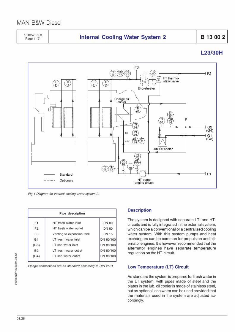
0802
8-0D
/H52
50/9
4.08
.12
MAN B&W Diesel
Internal Cooling Water System 2 B 13 00 2
L23/30H
1613576-9.3Page 1 (2)
01.26
Fig 1 Diagram for internal cooling water system 2.
DN 80
DN 80
DN 15
DN 80/100
DN 80/100
DN 80/100
DN 80/100
HT fresh water inlet
HT fresh water outlet
Venting to expansion tank
LT fresh water inlet
LT sea water inlet
LT fresh water outlet
LT sea water outlet
Pipe description
F1
F2
F3
G1
(G3)
G2
(G4)
Flange connections are as standard according to DIN 2501
Description
The system is designed with separate LT- and HT-circuits and is fully integrated in the external system,which can be a conventional or a centralized coolingwater system. With this system pumps and heatexchangers can be common for propulsion and alt-ernator engines. It is however, recommended that thealternator engines have separate temperatureregulation on the HT-circuit.
Low Temperature (LT) Circuit
As standard the system is prepared for fresh water inthe LT system, with pipes made of steel and theplates in the lub. oil cooler is made of stainless steel,but as optional, sea water can be used provided thatthe materials used in the system are adjusted ac-cordingly.
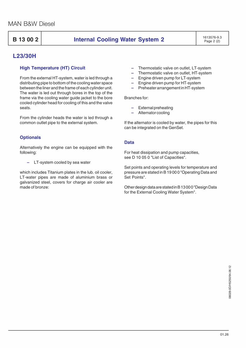
0802
8-0D
/H52
50/9
4.08
.12
MAN B&W Diesel
B 13 00 2 Internal Cooling Water System 2
L23/30H
01.26
1613576-9.3Page 2 (2)
High Temperature (HT) Circuit
From the external HT-system, water is led through adistributing pipe to bottom of the cooling water spacebetween the liner and the frame of each cylinder unit.The water is led out through bores in the top of theframe via the cooling water guide jacket to the borecooled cylinder head for cooling of this and the valveseats.
From the cylinder heads the water is led through acommon outlet pipe to the external system.
Optionals
Alternatively the engine can be equipped with thefollowing:
– LT-system cooled by sea water
which includes Titanium plates in the lub. oil cooler,LT-water pipes are made of aluminium brass orgalvanized steel, covers for charge air cooler aremade of bronze:
– Thermostatic valve on outlet, LT-system– Thermostatic valve on outlet, HT-system– Engine driven pump for LT-system– Engine driven pump for HT-system– Preheater arrangement in HT-system
Branches for:
– External preheating– Alternator cooling
If the alternator is cooled by water, the pipes for thiscan be integrated on the GenSet.
Data
For heat dissipation and pump capacities,see D 10 05 0 "List of Capacities".
Set points and operating levels for temperature andpressure are stated in B 19 00 0 "Operating Data andSet Points".
Other design data are stated in B 13 00 0 "Design Datafor the External Cooling Water System".
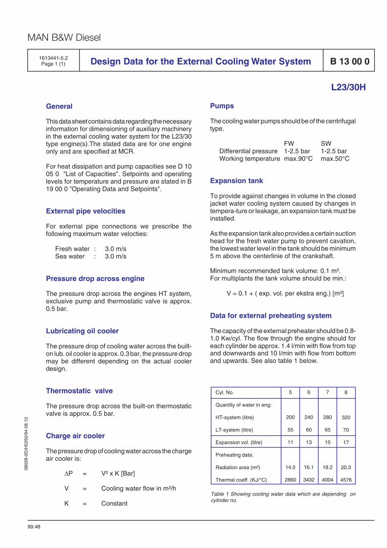
0802
8-0D
/H52
50/9
4.08
.12
MAN B&W Diesel
Pumps
The cooling water pumps should be of the centrifugaltype.
FW SWDifferential pressure 1-2.5 bar 1-2.5 barWorking temperature max.90°C max.50°C
Expansion tank
To provide against changes in volume in the closedjacket water cooling system caused by changes intempera-ture or leakage, an expansion tank must beinstalled.
As the expansion tank also provides a certain suctionhead for the fresh water pump to prevent cavation,the lowest water level in the tank should be minimum5 m above the centerlinie of the crankshaft.
Minimum recommended tank volume: 0.1 m³.For multiplants the tank volume should be min.:
V = 0.1 + ( exp. vol. per ekstra eng.) [m³]
Data for external preheating system
The capacity of the external preheater should be 0.8-1.0 Kw/cyl. The flow through the engine should foreach cylinder be approx. 1.4 l/min with flow from topand downwards and 10 l/min with flow from bottomand upwards. See also table 1 below.
General
This data sheet contains data regarding the necessaryinformation for dimensioning of auxiliary machineryin the external cooling water system for the L23/30type engine(s).The stated data are for one engineonly and are specified at MCR.
For heat dissipation and pump capacities see D 1005 0 "List of Capacities". Setpoints and operatinglevels for temperature and pressure are stated in B19 00 0 "Operating Data and Setpoints".
External pipe velocities
For external pipe connections we prescribe thefollowing maximum water velocties:
Fresh water : 3.0 m/sSea water : 3.0 m/s
Pressure drop across engine
The pressure drop across the engines HT system,exclusive pump and thermostatic valve is approx.0.5 bar.
Lubricating oil cooler
The pressure drop of cooling water across the built-on lub. oil cooler is approx. 0.3 bar, the pressure dropmay be different depending on the actual coolerdesign.
Thermostatic valve
The pressure drop across the built-on thermostaticvalve is approx. 0.5 bar.
Charge air cooler
The pressure drop of cooling water across the chargeair cooler is:
∆P = V² x K [Bar]
V = Cooling water flow in m³/h
K = Constant
Design Data for the External Cooling Water System B 13 00 0
99.48
L23/30H
1613441-5.2Page 1 (1)
Cyl. No.
Quantity of water in eng:
HT-system (litre)
LT-system (litre)
Expansion vol. (litre)
Preheating data:
Radiation area (m²)
Thermal coeff. (KJ/°C)
6
240
60
13
16.1
3432
7
280
65
15
18.2
4004
8
320
70
17
20.3
4576
5
200
55
11
14.0
2860
Table 1 Showing cooling water data which are depending oncylinder no.

0802
8-0D
/H52
50/9
4.08
.12
MAN B&W Diesel
B 13 00 0External Cooling Water System
91.38
Design of External Cooling Water System
It is not difficult to make a system fulfil the require-ments, but to make the system both simple andcheap and still fulfil the requirements of both theengine builder and other parties involved can be verydifficult. A simple version cannot be made withoutinvolving the engine builder.
The diagrams on the following pages are principaldiagrams, and are MAN B&W's recommendation forthe design of external cooling water systems.
The systems are designed on the basis of thefollowing criteria:
1. Simplicity.
2. Separate HT temperature regulation for pro-pulsion and alternator engines.
3. HT temperature regulation on engine outlet.
4. Preheating with surplus heat.
5. Preheating in engine top, downwards.
6. As few change-over valves as possible.
7. Possibility for Holeby ICS-system.
Ad 1) Cooling water systems have a tendency to beunnecessarily complicated and thus uneconomic ininstallation and operation. Therfore, we have attach-ed great importance to simple diagram design withoptimal cooling of the engines and at the same timeinstallation- and operation- friendly systems result-ing in economic advantages.
Ad 2) Cooling of alternator engines should be inde-pendent of the propulsion engine load and viceversa. Therefore, there should be separate coolingwater temperature regulation thus ensuring optimalrunning temperatures irrespective of load.
Ad 3) The HT FW thermostatic valve should bemounted on the engine's outlet side ensuring aconstant cooling water temperature above the en-gine at all loads.
General
1613442-7.0Page 1 (1)
If the thermostat valve is placed on the engine's inletside , which is not to be recommended, the tempera-ture on the engine depends on the load with the riskof overheating at full load.
Ad 4) It has been stressed on the diagrams that thealternator engines in stand-by position as well as thepropulsion engine in stop position are preheated,optimally and simply, with surplus heat from therunning engines.
Ad 5) If the engines are preheated with reversecooling water direction, i.e. from the top and down-wards, an optimal heat distribution is reached in theengine. This method is at the same time moreeconomic since the need for heating is less and thewater flow is reduced.
Ad 6) The systems have been designed in such away that the change-over from sea operation toharbour operation/stand-by with preheating can bemade with a minimum of manual or automatic inter-ference.
Ad 7) If the actual running situations demands thatone of the auxiliary engines should run on low-load,the systems have been designed so that one of theengines can be equipped with a cooling system forICS-operation(Integrated Charge air System).
Fresh Water Treatment
The engine cooling water is, like fuel oil and lubricat-ing oil, a medium which must be carefully selected,treated, maintained and monitored.
Otherwise, corrosion, corrosion fatigue and cavita-tion may occur on the surfaces of the cooling systemwhich are in contact with the water, and depositsmay form.
Corrosion and cavitation may reduce the life timeand safety factors of parts concerned, and depositswill impair the heat transfer and may result in thermaloverload of the components to be cooled.
The treatment process of the cooling water has to beeffected before the first commission of the plant, i.e.immediately after installation at the shipyard or at thepower plant.

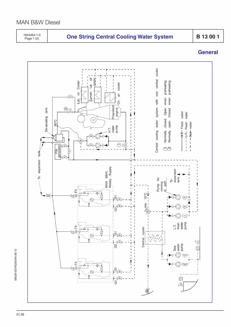
0802
8-0D
/H52
50/9
4.08
.12
MAN B&W Diesel
1624464-1.0Page 1 (2)
01.26
General
One String Central Cooling Water System B 13 00 1
0802
8-0D
/H52
50/9
4.08
.12
MAN B&W Diesel
01.26
1624464-1.0Page 2 (2)
System Design
The system is a central cooling water system ofsimple design with only one central cooler. Lowtemperature (LT) and fresh water (FW) pumps arecommon for all engines. In order to minimize thepower consumption the LT FW pump installationconsists of 3 pumps, two for sea operation andsmaller one for harbour operation.
The GenSet engines are connected as a one stringplant, with only one inlet- and outlet cooling waterconnection and with internal HT-circuit, see also B13 00 0 “Internal cooling water system 1”, describingthis system.
The propulsion engines HT-circuit is built up acc. tothe same principle, i.e. HT-water temperature isadjusted with LT-water mixing by means of thethermostatic valve.
The system is also remarkable for its preheating ofstand-by GenSet engines and propulsion engine byrunning GenSets, without extra pumps and heaters.
Preheating of Stand-by GenSets during Sea-operation:
GenSets in stand-by position are preheatedautomatically via the venting pipe with water from therunning engines. This is possible due to the pressuredifference, which the running GenSet engines HT-pumps produce.
Preheating of Stand-by GenSets and PropulsionEngine during Harbour Operation:
During harbour stay the propulsion and GenSetengines are also preheated in stand-by position bythe running GenSets. Valve (1) is open and valve (2)is closed. Thus the propulsion engine is heated fromtop and downwards, which is the most economicsolution.
B 13 00 1
General
One String Central Cooling Water System
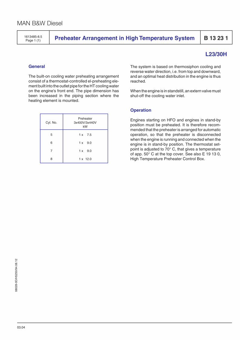
0802
8-0D
/H52
50/9
4.08
.12
MAN B&W Diesel
1613485-8.5Page 1 (1) Preheater Arrangement in High Temperature System B 13 23 1
L23/30H
03.04
General
The built-on cooling water preheating arrangementconsist of a thermostat-controlled el-preheating ele-ment built into the outlet pipe for the HT cooling wateron the engine's front end. The pipe dimension hasbeen increased in the piping section where theheating element is mounted.
Preheater3x400V/3x440V
kW
1 x 7.5
1 x 9.0
1 x 9.0
1 x 12.0
Cyl. No.
5
6
7
8
The system is based on thermosiphon cooling andreverse water direction, i.e. from top and downward,and an optimal heat distribution in the engine is thusreached.
When the engine is in standstill, an extern valve mustshut-off the cooling water inlet.
Operation
Engines starting on HFO and engines in stand-byposition must be preheated. It is therefore recom-mended that the preheater is arranged for automaticoperation, so that the preheater is disconnectedwhen the engine is running and connected when theengine is in stand-by position. The thermostat set-point is adjusted to 70° C, that gives a temperatureof app. 50° C at the top cover. See also E 19 13 0,High Temperature Preheater Control Box.


Compressed Air System
B 14

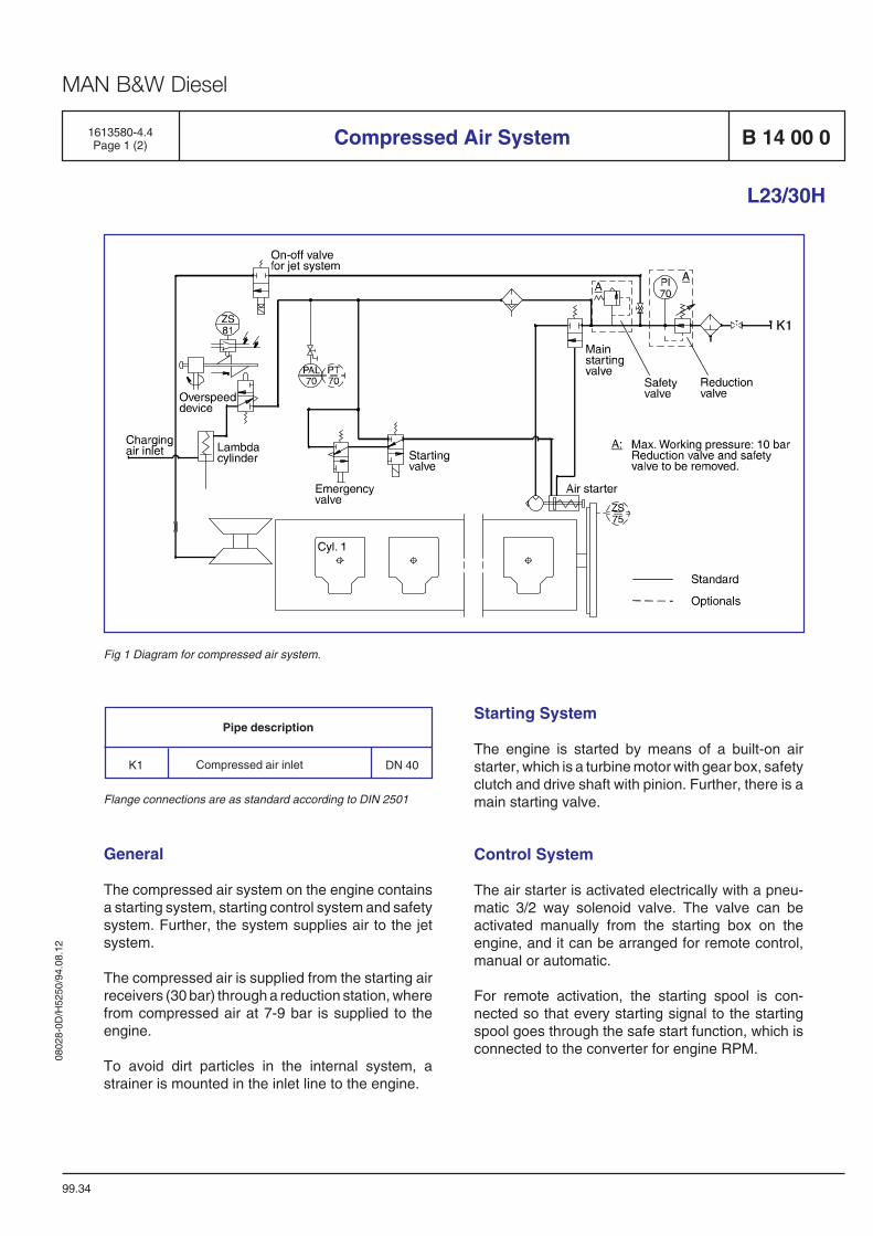
0802
8-0D
/H52
50/9
4.08
.12
MAN B&W Diesel
1613580-4.4Page 1 (2) Compressed Air System B 14 00 0
L23/30H
99.34
Fig 1 Diagram for compressed air system.
Starting System
The engine is started by means of a built-on airstarter, which is a turbine motor with gear box, safetyclutch and drive shaft with pinion. Further, there is amain starting valve.
Control System
The air starter is activated electrically with a pneu-matic 3/2 way solenoid valve. The valve can beactivated manually from the starting box on theengine, and it can be arranged for remote control,manual or automatic.
For remote activation, the starting spool is con-nected so that every starting signal to the startingspool goes through the safe start function, which isconnected to the converter for engine RPM.
Pipe description
DN 40Compressed air inletK1
Flange connections are as standard according to DIN 2501
General
The compressed air system on the engine containsa starting system, starting control system and safetysystem. Further, the system supplies air to the jetsystem.
The compressed air is supplied from the starting airreceivers (30 bar) through a reduction station, wherefrom compressed air at 7-9 bar is supplied to theengine.
To avoid dirt particles in the internal system, astrainer is mounted in the inlet line to the engine.
0802
8-0D
/H52
50/9
4.08
.12
MAN B&W Diesel
Further, the system is equipped with an emergencystarting valve which makes it possible to activate theair starter manually in case of a power failure.
Safety System
As standard the engine is equipped with a pneuma-tically/mechanically overspeed device, which startsto operate if the maximum permissible RPM is ex-ceeded. This device is fitted to the end cover of theengine driven lubricating pump and is driven from thepump through a resilient coupling.
When the maximum permissible RPM is exceeded,the overspeed device will activate a pneumaticallycontrolled stop cylinder, which will bring the fuelindex to zero and stop the engine.
Pneumatic Start Sequence
When the starting valve is opened, air will be sup-plied to the drive shaft housing of the air starter.
The air supply will - by activating a piston - bring thedrive pinion into engagement with the gear rim on theengine fly wheel.
When the pinion is fully engaged, the pilot air will flowto, and open the main starting valve, whereby air willbe led to the air starter, which will start to turn theengine.
B 14 00 0 Compressed Air System
L23/30H
99.34
1613580-4.4Page 2 (2)
When the RPM exceeds approx. 140, at which firinghas taken place, the starting valve is closed wherebythe air starter is disengaged.
Optionals
Besides the standard components, the followingstandard optionals can be built-on:
– Main stop valve, inlet engine
Pressure transmitting– PT 70 Compressed air inlet
Position switching, stop– ZS75 Microswitch on flywheel
Data
For air consumption pr. start, see D 10 05 0 "List ofCapacities".
Operating levels and set points, see B 19 00 0, "Ope-rating Data and Set Points.
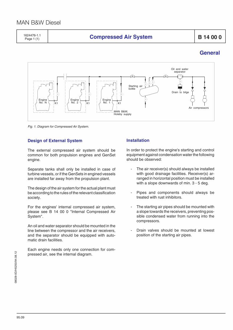
0802
8-0D
/H52
50/9
4.08
.12
MAN B&W Diesel
EngineNo. N
EngineNo. 2
EngineNo. 1
Starting airbottle
Oil and waterseparator
Drain to bilge
Air compressors
K1 K1K1
MAN B&W,Holeby supply
Fig. 1. Diagram for Compressed Air System.
Design of External System
The external compressed air system should becommon for both propulsion engines and GenSetengine.
Separate tanks shall only be installed in case ofturbine vessels, or if the GenSets in engined vesselsare installed far away from the propulsion plant.
The design of the air system for the actual plant mustbe according to the rules of the relevant classificationsociety.
For the engines' internal compressed air system,please see B 14 00 0 "Internal Compressed AirSystem".
An oil and water separator should be mounted in theline between the compressor and the air receivers,and the separator should be equipped with auto-matic drain facilities.
Each engine needs only one connection for com-pressed air, see the internal diagram.
Installation
In order to protect the engine's starting and controlequipment against condensation water the followingshould be observed:
- The air receiver(s) should always be installedwith good drainage facilities. Receiver(s) ar-ranged in horizontal position must be installedwith a slope downwards of min. 3 - 5 deg.
- Pipes and components should always betreated with rust inhibitors.
- The starting air pipes should be mounted witha slope towards the receivers, preventing pos-sible condensed water from running into thecompressors.
- Drain valves should be mounted at lowestposition of the starting air pipes.
95.09
Compressed Air System
General
B 14 00 01624476-1.1Page 1 (1)


Combustion Air System
B 15

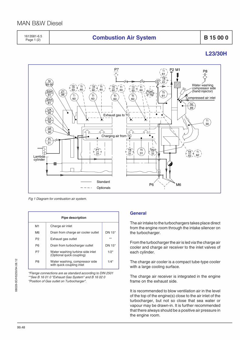
0802
8-0D
/H52
50/9
4.08
.12
MAN B&W Diesel
1613581-6.5Page 1 (2) Combustion Air System B 15 00 0
L23/30H
99.48
Fig 1 Diagram for combustion air system.
General
The air intake to the turbochargers takes place directfrom the engine room through the intake silencer onthe turbocharger.
From the turbocharger the air is led via the charge aircooler and charge air receiver to the inlet valves ofeach cylinder.
The charge air cooler is a compact tube-type coolerwith a large cooling surface.
The charge air receiver is integrated in the engineframe on the exhaust side.
It is recommended to blow ventilation air in the levelof the top of the engine(s) close to the air inlet of theturbocharger, but not so close that sea water orvapour may be drawn-in. It is further recommendedthat there always should be a positive air pressure inthe engine room.
Pipe description
DN 15*
**
DN 15*
1/2"
1/4"
Charge air inlet
Drain from charge air cooler outlet
Exhaust gas outlet
Drain from turbocharger outlet
Water washing turbine side inlet(Optional quick coupling)
Water washing, compressor sidewith quick coupling inlet
M1
M6
P2
P6
P7
P8
*Flange connections are as standard according to DIN 2501**See B 16 01 0 "Exhaust Gas System" and B 16 02 0"Position of Gas outlet on Turbocharger".
0802
8-0D
/H52
50/9
4.08
.12
MAN B&W Diesel
Water Mist Catcher
At outlet charge air cooler the charge air is ledthrough the water mist catcher. The water mistcatcher prevents condensed water (one of the majorcauses of cylinder wear) from entering the combustionchamber.
Turbocharger
The engine is as standard equipped with a high-effeciency MAN B&W, NR/R turbocharger of theradial type, which is located on the front end of theengine, mounted on the top plate of the charging aircooler housing.
Cleaning of Turbocharger
The turbocharger is fitted with an arrangement forwater washing of the turbine side, see B 16 01 1, andwater washing of the compressor side, see B 15 051. Soft blast cleaning on the turbine side can be fittedas optional, see B 16 01 2.
Lambda Controller
The purpose with the lambda controller is to preventinjection of more fuel in the combustion chamberthan can be burned during a momentary load in-crease. This is carried out by controlling the relationbetween the fuel index and the charge air pressure.
The lambda controller has the following advantages:
– Reduction of visible smoke in case of suddenmomentary load increases.
– Improved load ability.
– Less fouling of the engines exhaust gas ways.
– Limitating of fuel oil index during startingprocedure.
B 15 00 0 Combustion Air System
L23/30H
99.48
1613581-6.5Page 2 (2)
The above states that the working conditions areimproved under difficult circumstances and that themaintenance expenses for an engine, working withmany and major load changes, will be reduced.
Optionals
Besides the standard components, the followingstandard optionals can be built-on:
Pressure alarm low– PAL 35 Charge air, surplus air inlet
Pressure differential alarm low– PDAL 31-62, charge air and exhaust gas
Pressure transmitting– PT 31 Charge air, outlet from cooler
Temperature alarm high– TAH 31 Charge air, outlet from cooler
Temperature element– TE 31 Charge air, outlet from cooler– TE 60 Exhaust gas, outlet cylinder– TE 61 Exhaust gas, outlet turbocharger– TE 62 Exhaust gas, inlet turbocharger
Temperature indicating– TI 60 Exhaust gas, outlet cylinder– TI 61 Exhaust gas, outlet turbocharger– TI 62 Exhaust gas, inlet turbocharger
Data
For charge air heat dissipation and exhaust gasdata, see D 10 05 0 "List of Capacities".
Set points and operating levels for temperature andpressure are stated in B 19 00 0 "Operating Data andSet Points".
MAN B&W Diesel
1699110-4.0Page 1 (1) Engine Room Ventilation and Combustion Air B 15 00 0
General
05.10
Combustion Air Requirements
● The combustion air must be free from waterspray, dust, oil mist and exhaust gases.
● The air ventilation fans shoud be designed tomaintain a positive air pressure of 50 Pa (5mmWC) in the auxiliary engine room in allrunning conditions.
The combustion air is normally taken from theengine room through a filter fitted on the turbo-charger.
In tropical service a sufficient volume of air must besupplied to the turbocharger(s) at outside air tem-perature. For this purpose there must be an air ductinstalled for each turbocharger, with the outlet of theduct facing the respective intake air silencer. Nowater of condensation from the air duct must beallowed to be drawn in by the turbocharger.
In arctic service the air must be heated to at least0oC. If necessary air preheaters must be provided.
Ventilator Capacity
The capacity of the air ventilators must be largeenough to cover:
● The combustion air requirements of all con-sumers.
● The air required for carrying off the heat emis-sion.
See "List of Capacities" section D 10 05 0 forinformation about required combustion air quantityand heat emission.
For minimum requirements concerning engine roomventilation see applicable standards such as ISO8861.

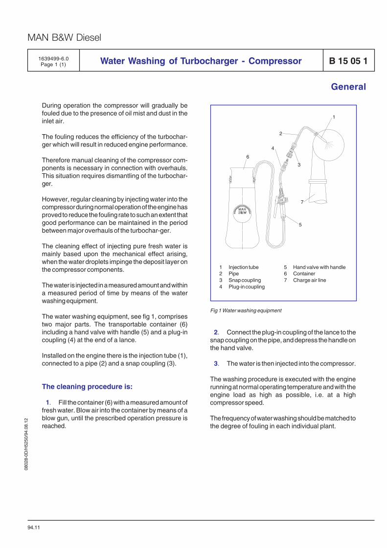
0802
8-0D
/H52
50/9
4.08
.12
MAN B&W Diesel
1639499-6.0Page 1 (1) Water Washing of Turbocharger - Compressor B 15 05 1
94.11
General
During operation the compressor will gradually befouled due to the presence of oil mist and dust in theinlet air.
The fouling reduces the efficiency of the turbochar-ger which will result in reduced engine performance.
Therefore manual cleaning of the compressor com-ponents is necessary in connection with overhauls.This situation requires dismantling of the turbochar-ger.
However, regular cleaning by injecting water into thecompressor during normal operation of the engine hasproved to reduce the fouling rate to such an extent thatgood performance can be maintained in the periodbetween major overhauls of the turbochar-ger.
The cleaning effect of injecting pure fresh water ismainly based upon the mechanical effect arising,when the water droplets impinge the deposit layer onthe compressor components.
The water is injected in a measured amount and withina measured period of time by means of the waterwashing equipment.
The water washing equipment, see fig 1, comprisestwo major parts. The transportable container (6)including a hand valve with handle (5) and a plug-incoupling (4) at the end of a lance.
Installed on the engine there is the injection tube (1),connected to a pipe (2) and a snap coupling (3).
The cleaning procedure is:
1. Fill the container (6) with a measured amount offresh water. Blow air into the container by means of ablow gun, until the prescribed operation pressure isreached.
2. Connect the plug-in coupling of the lance to thesnap coupling on the pipe, and depress the handle onthe hand valve.
3. The water is then injected into the compressor.
The washing procedure is executed with the enginerunning at normal operating temperature and with theengine load as high as possible, i.e. at a highcompressor speed.
The frequency of water washing should be matched tothe degree of fouling in each individual plant.
1 Injection tube 5 Hand valve with handle2 Pipe 6 Container3 Snap coupling 7 Charge air line4 Plug-in coupling
Fig 1 Water washing equipment

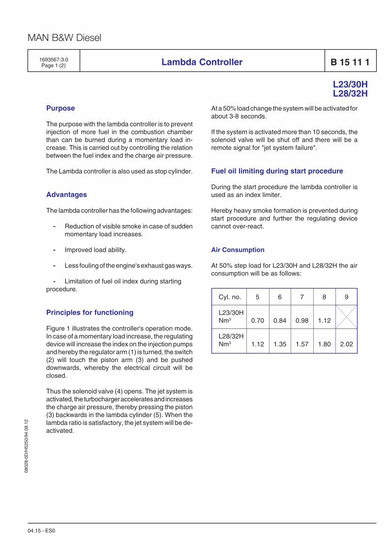
0802
8-0D
/H52
50/9
4.08
.12
MAN B&W Diesel
1693567-3.0Page 1 (2) B 15 11 1
At a 50% load change the system will be activated forabout 3-8 seconds.
If the system is activated more than 10 seconds, thesolenoid valve will be shut off and there will be aremote signal for "jet system failure".
Fuel oil limiting during start procedure
During the start procedure the lambda controller isused as an index limiter.
Hereby heavy smoke formation is prevented duringstart procedure and further the regulating devicecannot over-react.
Air Consumption
At 50% step load for L23/30H and L28/32H the airconsumption will be as follows:
Cyl. no. 5 6 7 8 9
L23/30HNm3 0.70 0.84 0.98 1.12
L28/32HNm3 1.12 1.35 1.57 1.80 2.02
Lambda Controller
04.15 - ES0
L23/30HL28/32H
Purpose
The purpose with the lambda controller is to preventinjection of more fuel in the combustion chamberthan can be burned during a momentary load in-crease. This is carried out by controlling the relationbetween the fuel index and the charge air pressure.
The Lambda controller is also used as stop cylinder.
Advantages
The lambda controller has the following advantages:
- Reduction of visible smoke in case of suddenmomentary load increases.
- Improved load ability.
- Less fouling of the engine's exhaust gas ways.
- Limitation of fuel oil index during startingprocedure.
Principles for functioning
Figure 1 illustrates the controller's operation mode.In case of a momentary load increase, the regulatingdevice will increase the index on the injection pumpsand hereby the regulator arm (1) is turned, the switch(2) will touch the piston arm (3) and be pusheddownwards, whereby the electrical circuit will beclosed.
Thus the solenoid valve (4) opens. The jet system isactivated, the turbocharger accelerates and increasesthe charge air pressure, thereby pressing the piston(3) backwards in the lambda cylinder (5). When thelambda ratio is satisfactory, the jet system will be de-activated.
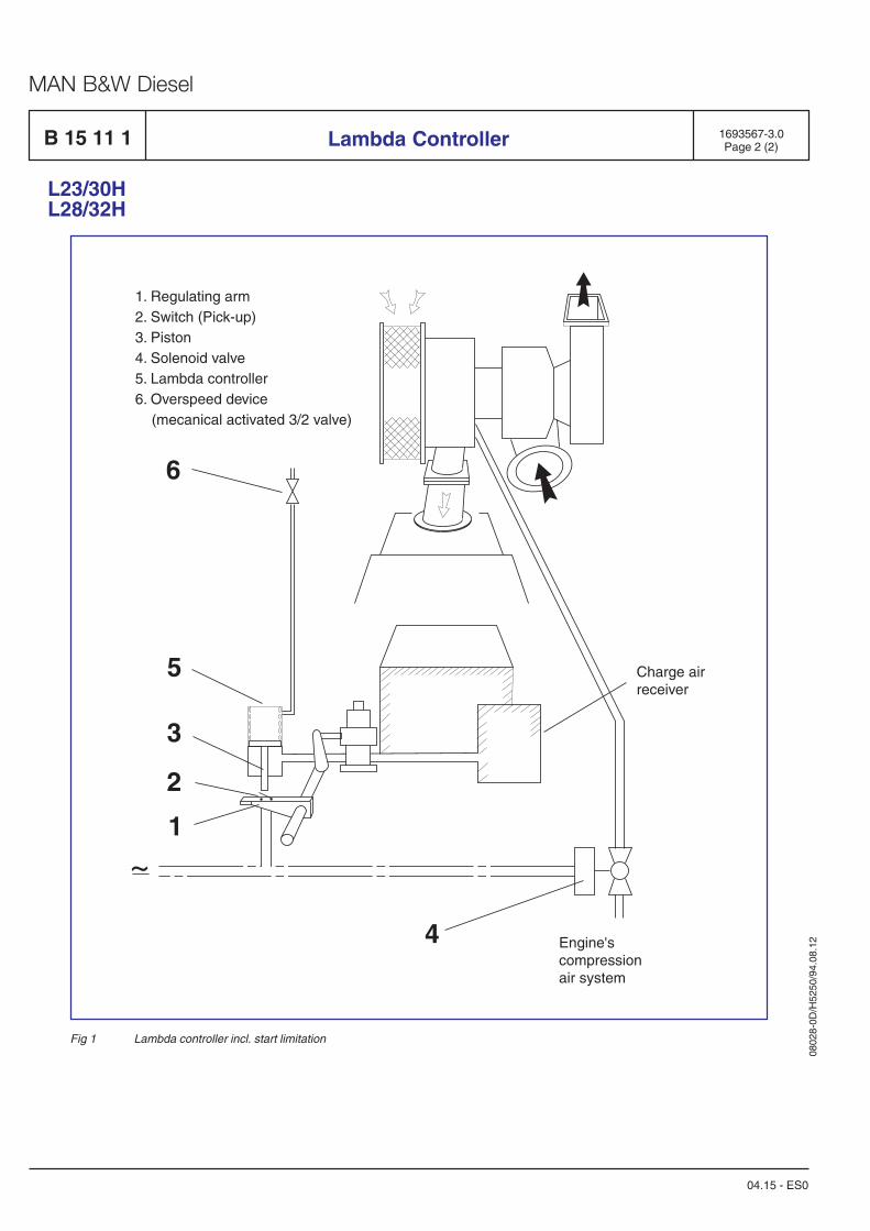
0802
8-0D
/H52
50/9
4.08
.12
MAN B&W Diesel
B 15 11 1
Fig 1 Lambda controller incl. start limitation
~
Charge airreceiver
Engine'scompressionair system
4
1
2
3
5
6
1. Regulating arm2. Switch (Pick-up)3. Piston4. Solenoid valve5. Lambda controller6. Overspeed device
(mecanical activated 3/2 valve)
1693567-3.0Page 2 (2)Lambda Controller
L23/30HL28/32H
04.15 - ES0

Exhaust Gas System
B 16

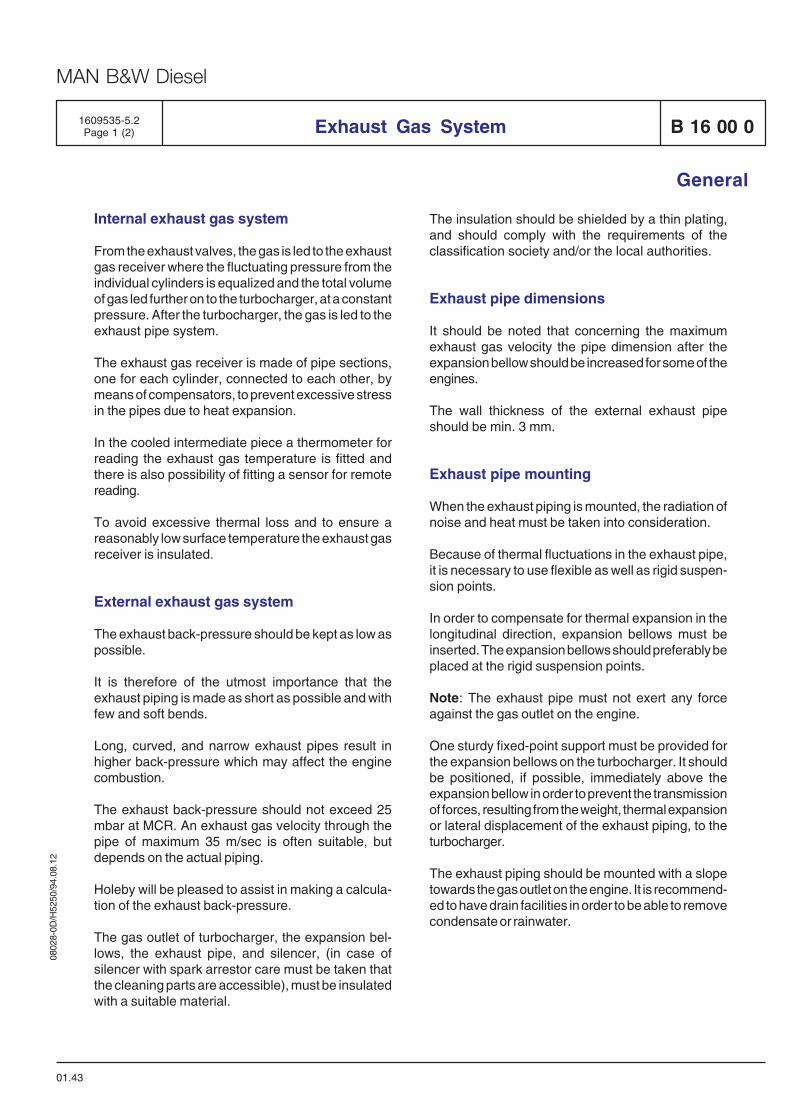
0802
8-0D
/H52
50/9
4.08
.12
MAN B&W Diesel
01.43
General
1609535-5.2Page 1 (2) Exhaust Gas System B 16 00 0
Internal exhaust gas system
From the exhaust valves, the gas is led to the exhaustgas receiver where the fluctuating pressure from theindividual cylinders is equalized and the total volumeof gas led further on to the turbocharger, at a constantpressure. After the turbocharger, the gas is led to theexhaust pipe system.
The exhaust gas receiver is made of pipe sections,one for each cylinder, connected to each other, bymeans of compensators, to prevent excessive stressin the pipes due to heat expansion.
In the cooled intermediate piece a thermometer forreading the exhaust gas temperature is fitted andthere is also possibility of fitting a sensor for remotereading.
To avoid excessive thermal loss and to ensure areasonably low surface temperature the exhaust gasreceiver is insulated.
External exhaust gas system
The exhaust back-pressure should be kept as low aspossible.
It is therefore of the utmost importance that theexhaust piping is made as short as possible and withfew and soft bends.
Long, curved, and narrow exhaust pipes result inhigher back-pressure which may affect the enginecombustion.
The exhaust back-pressure should not exceed 25mbar at MCR. An exhaust gas velocity through thepipe of maximum 35 m/sec is often suitable, butdepends on the actual piping.
Holeby will be pleased to assist in making a calcula-tion of the exhaust back-pressure.
The gas outlet of turbocharger, the expansion bel-lows, the exhaust pipe, and silencer, (in case ofsilencer with spark arrestor care must be taken thatthe cleaning parts are accessible), must be insulatedwith a suitable material.
The insulation should be shielded by a thin plating,and should comply with the requirements of theclassification society and/or the local authorities.
Exhaust pipe dimensions
It should be noted that concerning the maximumexhaust gas velocity the pipe dimension after theexpansion bellow should be increased for some of theengines.
The wall thickness of the external exhaust pipeshould be min. 3 mm.
Exhaust pipe mounting
When the exhaust piping is mounted, the radiation ofnoise and heat must be taken into consideration.
Because of thermal fluctuations in the exhaust pipe,it is necessary to use flexible as well as rigid suspen-sion points.
In order to compensate for thermal expansion in thelongitudinal direction, expansion bellows must beinserted. The expansion bellows should preferably beplaced at the rigid suspension points.
Note: The exhaust pipe must not exert any forceagainst the gas outlet on the engine.
One sturdy fixed-point support must be provided forthe expansion bellows on the turbocharger. It shouldbe positioned, if possible, immediately above theexpansion bellow in order to prevent the transmissionof forces, resulting from the weight, thermal expansionor lateral displacement of the exhaust piping, to theturbocharger.
The exhaust piping should be mounted with a slopetowards the gas outlet on the engine. It is recommend-ed to have drain facilities in order to be able to removecondensate or rainwater.
0802
8-0D
/H52
50/9
4.08
.12
MAN B&W Diesel
B 16 00 0 Exhaust Gas System
01.43
General
1609535-5.2Page 2 (2)
Position of gas outlet on turbocharger
B 16 02 0 shows turning alternatives positions of theexhaust gas outlet. Before dispatch of the enginefrom Holeby exhaust gas outlet will be turned to thewanted position.
The turbocharger is, as standard, mounted in the frontend.
Exhaust gas boiler
To utilize the thermal energy from the exhaust, anexhaust gas boiler producing steam or hot water canbe installed.
Each engine should have a separate exhaust gasboiler or, alternatively, a common boiler with separategas ducts. Concerning exhaust gas quantities andtemperature, see list of capacities D 10 05 0, andengine performance D 10 10 0.
The discharge temperature from the exhaust gasboiler should not be lower than 180° C (in order to avoidsulphuric acid formation in the funnel).
The exhaust gas boilers should be installed with by-pass entering in function at low load operation.
The back-pressure over the boiler must be consid-ered.
Expansion bellow
The expansion bellow, which is supplied separately,must be mounted directly on the exhaust gas outlet,see also E 16 01 1-2.
Exhaust silencer
The position of the silencer in the exhaust gas pipingis not decisive for the silencing effect. It would beuseful, however, to fit the silencer as high as possibleto reduce fouling. The necessary silencing dependson the loudness of the exhaust sound and the dis-charge from the gas outlet to the bridge wing.
The exhaust silencer, see E 16 04 2-3-5-6 is suppliedloose with counterflange, gaskets and bolts.
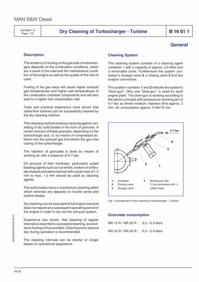
0802
8-0D
/H52
50/9
4.08
.12
MAN B&W Diesel
General
Description
The tendency to fouling on the gas side of turbochar-gers depends on the combustion conditions, whichare a result of the load and the maintenance condi-tion of the engine as well as the quality of the fuel oilused.
Fouling of the gas ways will cause higher exhaustgas temperatures and higher wall temperatures ofthe combustion chamber components and will alsolead to a higher fuel consumption rate.
Tests and practical experience have shown thatradial-flow turbines can be successfully cleaned bythe dry cleaning method.
This cleaning method employs cleaning agents con-sisting of dry solid bodies in the form of granules. Acertain amount of these granules, depending on theturbocharger size, is, by means of compressed air,blown into the exhaust gas line before the gas inletcasing of the turbocharger.
The injection of granulate is done by means ofworking air with a pressure of 5-7 bar.
On account of their hardness, particularly suitedblasting agents such as nut-shells, broken or artifici-ally shaped activated charcoal with a grain size of 1.0mm to max. 1.5 mm should be used as cleaningagents.
The solid bodies have a mechanical cleaning effectwhich removes any deposits on nozzle vanes andturbine blades.
Dry cleaning can be executed at full engine load anddoes not require any subsequent operating period ofthe engine in order to dry out the exhaust system.
Experience has shown, that cleaning of regularintervals is essential to successful cleaning, as exce-ssive fouling is thus avoided. Cleaning every secondday during operation is recommended.
The cleaning intervals can be shorter or longerbased on operational experience.
04.28
1607599-1.4Page 1 (3) Dry Cleaning of Turbocharger - Turbine B 16 01 1
2 1
3
4
5-7 bar
1. Container 4. Working air inlet2. Closing valve To be connected with ½3. Dosage valve rubber hose.
Fig 1 Arrangement of dry cleaning of turbocharger - Turbine.
Granulate consumption
NR 15 R / NR 20 R : 0.2 - 0.3 liters
NR 24 R / NR 26 R : 0.3 - 0.4 liters
Cleaning System
The cleaning system consists of a cleaning agentcontainer 1 with a capacity of approx. 0.5 liters anda removable cover. Furthermore the system con-sistsof a dosage valve 3, a closing valve 2 and twosnapon connectors.
The position numbers 1 and 3 indicate the system's"blow-gun". Only one "blow-gun" is used for eachengine plant. The blow-gun is working according tothe ejector principle with pressure air (working air) at5-7 bar as driven medium. Injection time approx. 2min. Air consumption approx. 5 Nm3/2 min.
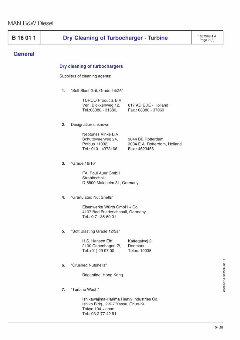
0802
8-0D
/H52
50/9
4.08
.12
MAN B&W Diesel
General
04.28
Dry cleaning of turbochargers
Suppliers of cleaning agents:
1. "Solf Blast Grit, Grade 14/25"
TURCO Products B.V.Verl. Blokkenweg 12, 617 AD EDE - HollandTel.:08380 - 31380, Fax.: 08380 - 37069
2. Designation unknown
Neptunes Vinke B.V.Schuttevaerweg 24, 3044 BB RotterdamPotbus 11032, 3004 E.A. Rotterdam, HollandTel.: 010 - 4373166 Fax.: 4623466
3. "Grade 16/10"
FA. Poul Auer GmbHStrahltechnikD-6800 Mainheim 31, Germany
4. "Granulated Nut Shells"
Eisenwerke Würth GmbH + Co.4107 Bad Friederichshall, GermanyTel.: 0 71 36-60 01
5. "Soft Blasting Grade 12/3a"
H.S. Hansen Eftf. Kattegatvej 22100 Copenhagen Ø, DenmarkTel.:(01) 29 97 00 Telex: 19038
6. "Crushed Nutshells"
Brigantine, Hong Kong
7. "Turbine Wash"
Ishikawajima-Harima Heavy Industries Co.Ishiko Bldg., 2-9-7 Yassu, Chuo-KuTokyo 104, JapanTel.: 03-2 77-42 91
1607599-1.4Page 2 (3)B 16 01 1 Dry Cleaning of Turbocharger - Turbine
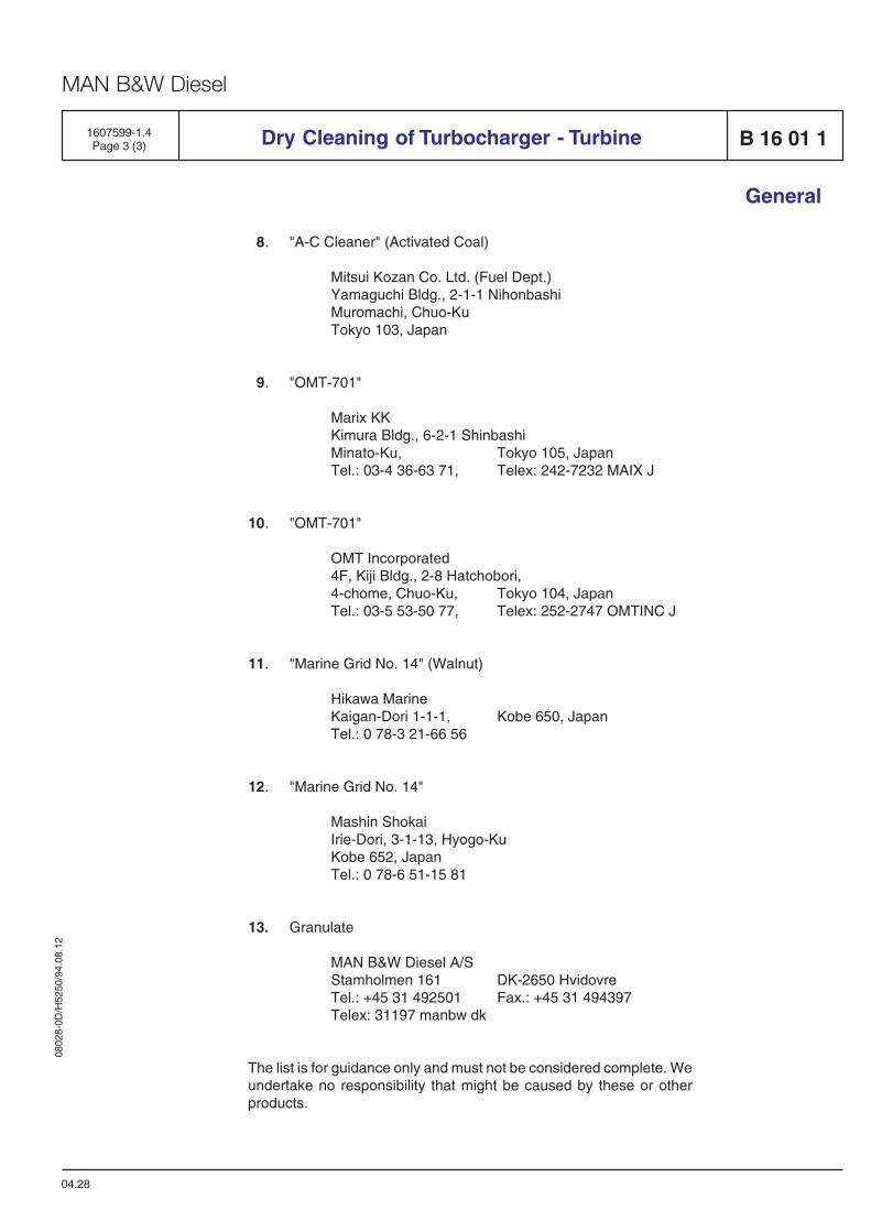
0802
8-0D
/H52
50/9
4.08
.12
MAN B&W Diesel
8. "A-C Cleaner" (Activated Coal)
Mitsui Kozan Co. Ltd. (Fuel Dept.)Yamaguchi Bldg., 2-1-1 NihonbashiMuromachi, Chuo-KuTokyo 103, Japan
9. "OMT-701"
Marix KKKimura Bldg., 6-2-1 ShinbashiMinato-Ku, Tokyo 105, JapanTel.: 03-4 36-63 71, Telex: 242-7232 MAIX J
10. "OMT-701"
OMT Incorporated4F, Kiji Bldg., 2-8 Hatchobori,4-chome, Chuo-Ku, Tokyo 104, JapanTel.: 03-5 53-50 77, Telex: 252-2747 OMTINC J
11. "Marine Grid No. 14" (Walnut)
Hikawa MarineKaigan-Dori 1-1-1, Kobe 650, JapanTel.: 0 78-3 21-66 56
12. "Marine Grid No. 14"
Mashin ShokaiIrie-Dori, 3-1-13, Hyogo-KuKobe 652, JapanTel.: 0 78-6 51-15 81
13. Granulate
MAN B&W Diesel A/SStamholmen 161 DK-2650 HvidovreTel.: +45 31 492501 Fax.: +45 31 494397Telex: 31197 manbw dk
The list is for guidance only and must not be considered complete. Weundertake no responsibility that might be caused by these or otherproducts.
Dry Cleaning of Turbocharger - Turbine
04.28
B 16 01 11607599-1.4Page 3 (3)
General

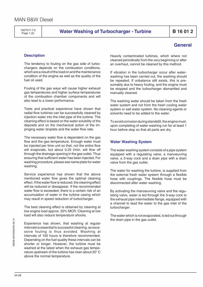
0802
8-0D
/H52
50/9
4.08
.12
MAN B&W Diesel
General
04.28
B 16 01 2Water Washing of Turbocharger - Turbine1607517-7.5Page 1 (2)
Description
The tendency to fouling on the gas side of turbo-chargers depends on the combustion conditions,which are a result of the load on and the maintenancecondition of the engine as well as the quality of thefuel oil used.
Fouling of the gas ways will cause higher exhaustgas temperatures and higher surface temperaturesof the combustion chamber components and willalso lead to a lower performance.
Tests and practical experience have shown thatradial-flow turbines can be successfully cleaned byinjection water into the inlet pipe of the turbine. Thecleaning effect is based on the water solubility of thedeposits and on the mechanical action of the im-pinging water droplets and the water flow rate.
The necessary water flow is dependent on the gasflow and the gas temperature. Enough water mustbe injected per time unit so that, not the entire flowwill evaporate, but about 0.25 l/min. will flow offthrough the drainage opening in the gas outlet. Thusensuring that sufficient water has been injected. Forwashing procedure, please see name plate for waterwashing.
Service experience has shown that the abovementioned water flow gives the optimal cleaningeffect. If the water flow is reduced, the cleaning effectwill be reduced or dissappear. If the recommendedwater flow is exceeded, there is a certain risk of anaccumulation of water in the turbine casing whichmay result in speed reduction of turbocharger.
The best cleaning effect is obtained by cleaning atlow engine load approx. 20% MCR. Cleaning at lowload will also reduce temperature shocks.
Experience has shown, that washing at regularintervals is essential to successful cleaning, as exce-ssive fouling is thus avoided. Washing atintervals of 100 hours is therefore recommended.Depending on the fuel quality these intervals can beshorter or longer. However, the turbine must bewashed at the latest when the exhaust gas tempe-rature upstream of the turbine has risen about 20° Cabove the normal temperature.
Heavily contaminated turbines, which where notcleaned periodically from the very beginning or afteran overhaul, cannot be cleaned by this method.
If vibration in the turbocharger occur after water-washing has been carried out, the washing shouldbe repeated. If unbalance still exists, this is pre-sumably due to heavy fouling, and the engine mustbe stopped and the turbocharger dismantled andmanually cleaned.
The washing water should be taken from the freshwater system and not from the fresh cooling watersystem or salt water system. No cleaning agents orsolvents need to be added to the water.
To avoid corrosion during standstill, the engine must,upon completing of water washing run far at least 1hour before stop so that all parts are dry.
Water Washing System
The water washing system consists of a pipe systemequipped with a regulating valve, a manoeuvringvalve, a 3-way cock and a drain pipe with a drainvalve from the gas outlet.
The water for washing the turbine, is supplied fromthe external fresh water system through a flexiblehose with couplings. The flexible hose must bedisconnected after water washing.
By activating the manoeuvring valve and the regu-lating valve, water is led through the 3-way cock tothe exhaust pipe intermediate flange, equipped witha channel to lead the water to the gas inlet of theturbocharger.
The water which is not evaporated, is led out throughthe drain pipe in the gas outlet.
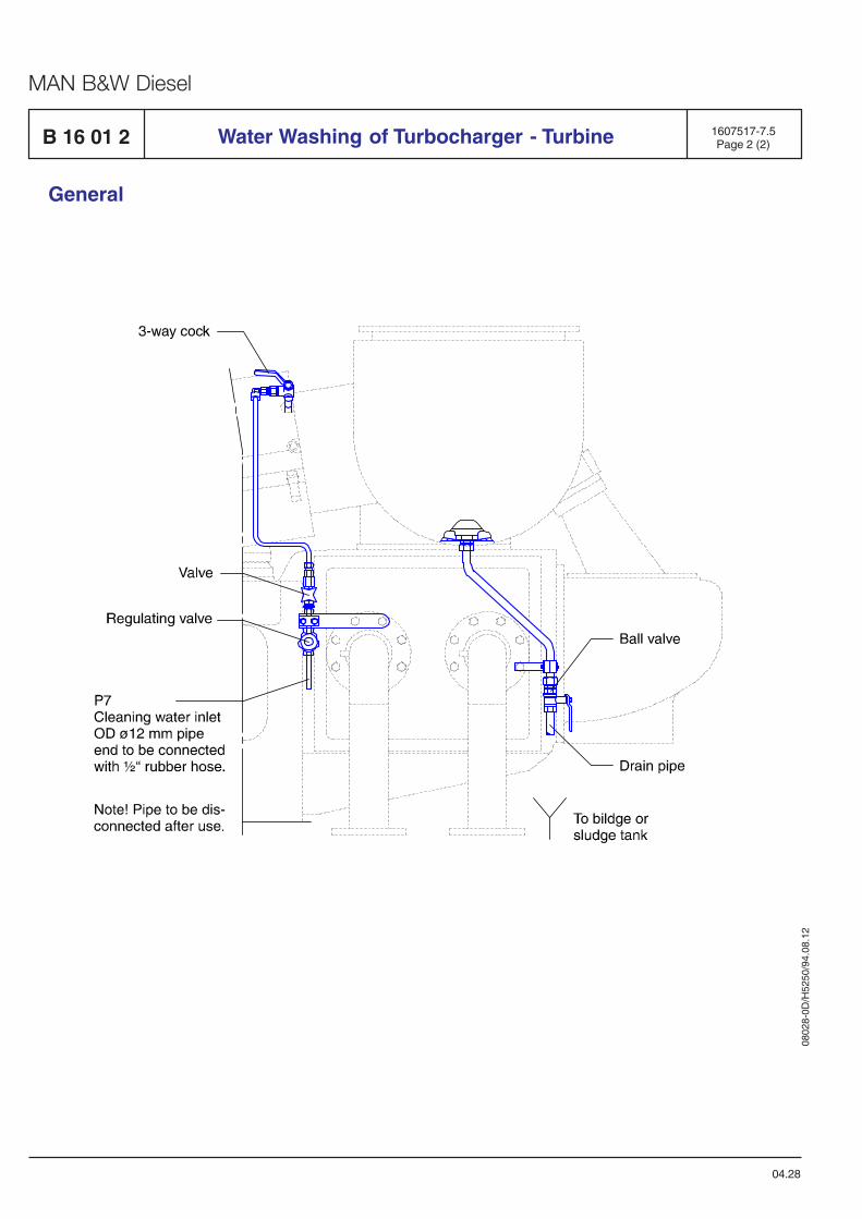
0802
8-0D
/H52
50/9
4.08
.12
MAN B&W Diesel
General
1607517-7.5Page 2 (2)Water Washing of Turbocharger - TurbineB 16 01 2
04.28
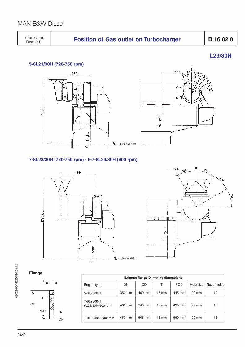
0802
8-0D
/H52
50/9
4.08
.12
MAN B&W Diesel
1613417-7.3Page 1 (1) Position of Gas outlet on Turbocharger B 16 02 0
L23/30H5-6L23/30H (720-750 rpm)
- Crankshaft
7-8L23/30H (720-750 rpm) - 6-7-8L23/30H (900 rpm)
- Crankshaft
DN
350 mm
400 mm
450 mm
OD
490 mm
540 mm
595 mm
T
16 mm
16 mm
16 mm
Engine type
5-6L23/30H
7-8L23/30H6L23/30H-900 rpm
7-8L23/30H-900 rpm
Exhaust flange D. mating dimensions
PCD
445 mm
495 mm
550 mm
Hole size
22 mm
22 mm
22 mm
No. of holes
12
16
16
Flange
99.40
T
123123123123123123123
123123
OD
PCD
DN

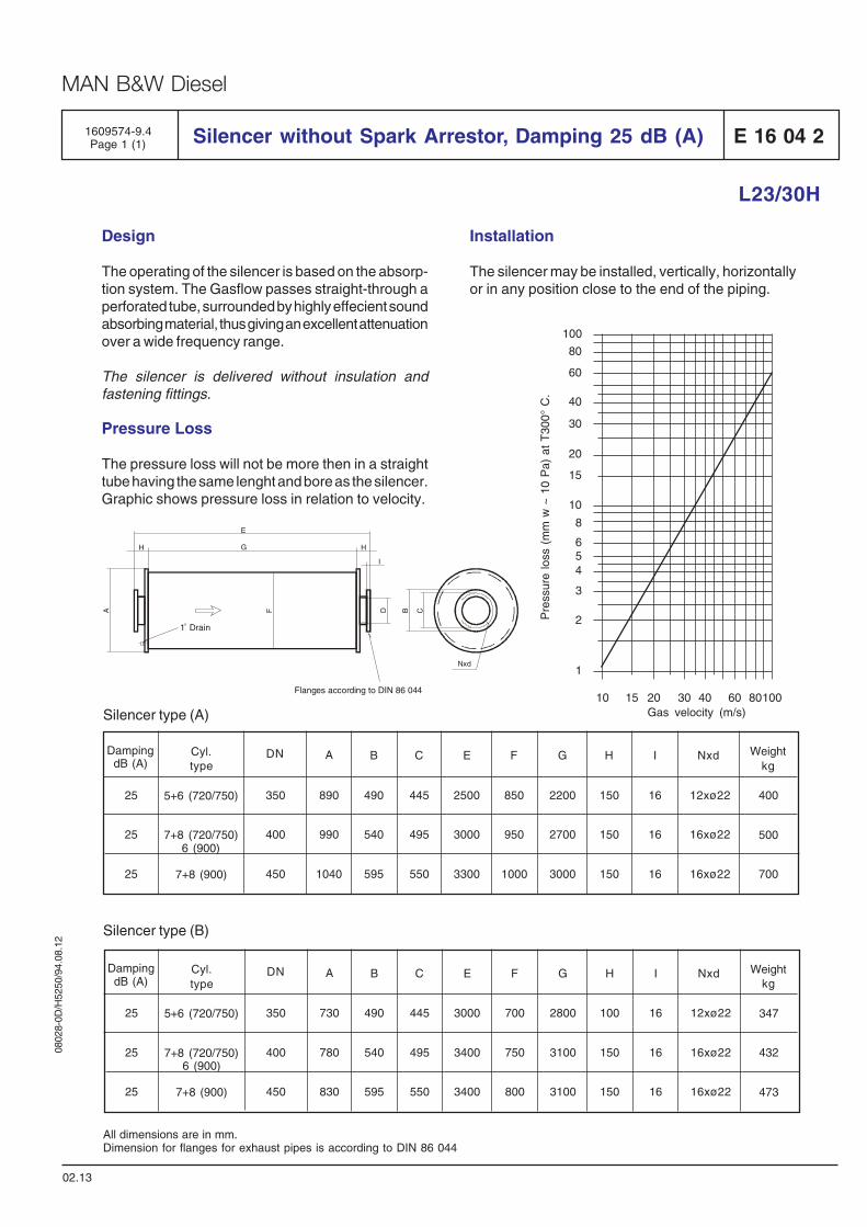
0802
8-0D
/H52
50/9
4.08
.12
MAN B&W Diesel
L23/30H
E 16 04 2Silencer without Spark Arrestor, Damping 25 dB (A)1609574-9.4Page 1 (1)
Design
The operating of the silencer is based on the absorp-tion system. The Gasflow passes straight-through aperforated tube, surrounded by highly effecient soundabsorbing material, thus giving an excellent attenuationover a wide frequency range.
The silencer is delivered without insulation andfastening fittings.
Pressure Loss
The pressure loss will not be more then in a straighttube having the same lenght and bore as the silencer.Graphic shows pressure loss in relation to velocity.
02.13
Silencer type (A)
Silencer type (B)
All dimensions are in mm.Dimension for flanges for exhaust pipes is according to DIN 86 044
Installation
The silencer may be installed, vertically, horizontallyor in any position close to the end of the piping.
60
80
30
20
15
10
8
654
3
2
1
40
100
Pre
ssur
e lo
ss (
mm
w ~
10
Pa)
at
T30
0° C
.
10 15 20 30 40 60 80100Gas velocity (m/s)
Weightkg
NxdIHGFECBDN ACyl.type
DampingdB (A)
25
25
25
350
400
450
890
990
1040
490
540
595
445
495
550
2500
3000
3300
850
950
1000
2200
2700
3000
150
150
150
16
16
16
12xø22
16xø22
16xø22
400
500
700
5+6 (720/750)
7+8 (720/750)6 (900)
7+8 (900)
Weightkg
NxdIHGFECBDN ACyl.type
DampingdB (A)
25
25
25
350
400
450
730
780
830
490
540
595
445
495
550
3000
3400
3400
700
750
800
2800
3100
3100
100
150
150
16
16
16
12xø22
16xø22
16xø22
347
432
473
5+6 (720/750)
7+8 (720/750)6 (900)
7+8 (900)
Nxd
CBDFA
I
HH G
E
Flanges according to DIN 86 044
1 Drain

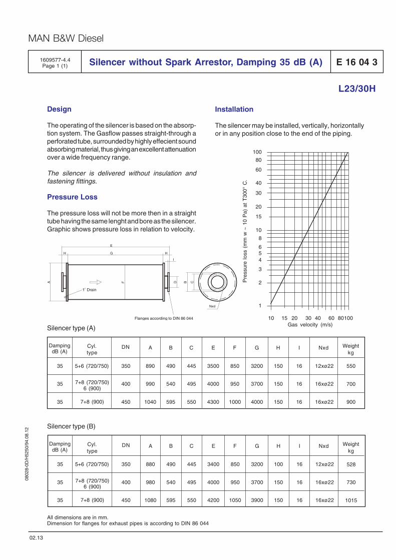
0802
8-0D
/H52
50/9
4.08
.12
MAN B&W Diesel
L23/30H
E 16 04 3Silencer without Spark Arrestor, Damping 35 dB (A)1609577-4.4Page 1 (1)
Design
The operating of the silencer is based on the absorp-tion system. The Gasflow passes straight-through aperforated tube, surrounded by highly effecient soundabsorbing material, thus giving an excellent attenuationover a wide frequency range.
The silencer is delivered without insulation andfastening fittings.
Pressure Loss
The pressure loss will not be more then in a straighttube having the same lenght and bore as the silencer.Graphic shows pressure loss in relation to velocity.
02.13
Silencer type (A)
Silencer type (B)
All dimensions are in mm.Dimension for flanges for exhaust pipes is according to DIN 86 044
60
80
30
20
15
10
8
654
3
2
1
40
100
10 15 20 30 40 60 80100Gas velocity (m/s)
Pre
ssur
e lo
ss (
mm
w ~
10
Pa)
at
T30
0° C
.
Installation
The silencer may be installed, vertically, horizontallyor in any position close to the end of the piping.
Weightkg
NxdIHGFECBDN ACyl.type
DampingdB (A)
35
35
35
350
400
450
890
990
1040
490
540
595
445
495
550
3500
4000
4300
850
950
1000
3200
3700
4000
150
150
150
16
16
16
12xø22
16xø22
16xø22
550
700
9007+8 (900)
5+6 (720/750)
7+8 (720/750)6 (900)
Weightkg
NxdIHGFECBDN ACyl.type
DampingdB (A)
35
35
35
350
400
450
880
980
1080
490
540
595
445
495
550
3400
4000
4200
850
950
1050
3200
3700
3900
100
150
150
16
16
16
12xø22
16xø22
16xø22
528
730
10157+8 (900)
5+6 (720/750)
7+8 (720/750)6 (900)
Nxd
CBDFA
I
HH G
E
Flanges according to DIN 86 044
1 Drain

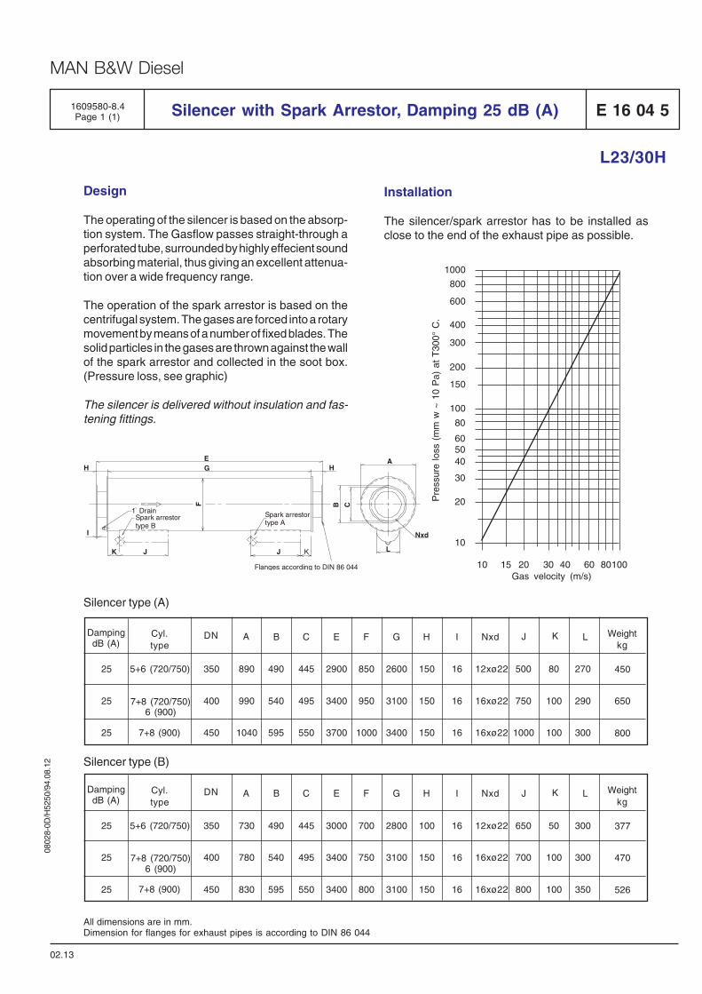
0802
8-0D
/H52
50/9
4.08
.12
MAN B&W Diesel
L23/30H
E 16 04 5Silencer with Spark Arrestor, Damping 25 dB (A)1609580-8.4Page 1 (1)
02.13
All dimensions are in mm.Dimension for flanges for exhaust pipes is according to DIN 86 044
Design
The operating of the silencer is based on the absorp-tion system. The Gasflow passes straight-through aperforated tube, surrounded by highly effecient soundabsorbing material, thus giving an excellent attenua-tion over a wide frequency range.
The operation of the spark arrestor is based on thecentrifugal system. The gases are forced into a rotarymovement by means of a number of fixed blades. Thesolid particles in the gases are thrown against the wallof the spark arrestor and collected in the soot box.(Pressure loss, see graphic)
The silencer is delivered without insulation and fas-tening fittings.
Silencer type (B)
Silencer type (A)
600
800
300
200
150
100
80
605040
30
20
10
400
1000
10 15 20 30 40 60 80100Gas velocity (m/s)
Pre
ssur
e lo
ss (
mm
w ~
10
Pa)
at
T30
0° C
.
Installation
The silencer/spark arrestor has to be installed asclose to the end of the exhaust pipe as possible.
Weightkg
NxdIHGFECBDN ACyl.type
DampingdB (A)
K LJ
25
25
25
350
400
450
890
990
1040
490
540
595
445
495
550
2900
3400
3700
850
950
1000
2600
3100
3400
150
150
150
16
16
16
12xø22
16xø22
16xø22
500
750
1000
80
100
100
270
290
300
450
650
8007+8 (900)
5+6 (720/750)
7+8 (720/750)6 (900)
Weightkg
NxdIHGFECBDN ACyl.type
DampingdB (A)
K LJ
25
25
25
350
400
450
730
780
830
490
540
595
445
495
550
3000
3400
3400
700
750
800
2800
3100
3100
100
150
150
16
16
16
12xø22
16xø22
16xø22
650
700
800
50
100
100
300
300
350
377
470
5267+8 (900)
5+6 (720/750)
7+8 (720/750)6 (900)
Flanges according to DIN 86 044
EGH
I
K J J K L
A
B CF
Spark arrestortype A
Spark arrestortype B
1 Drain
Nxd
H

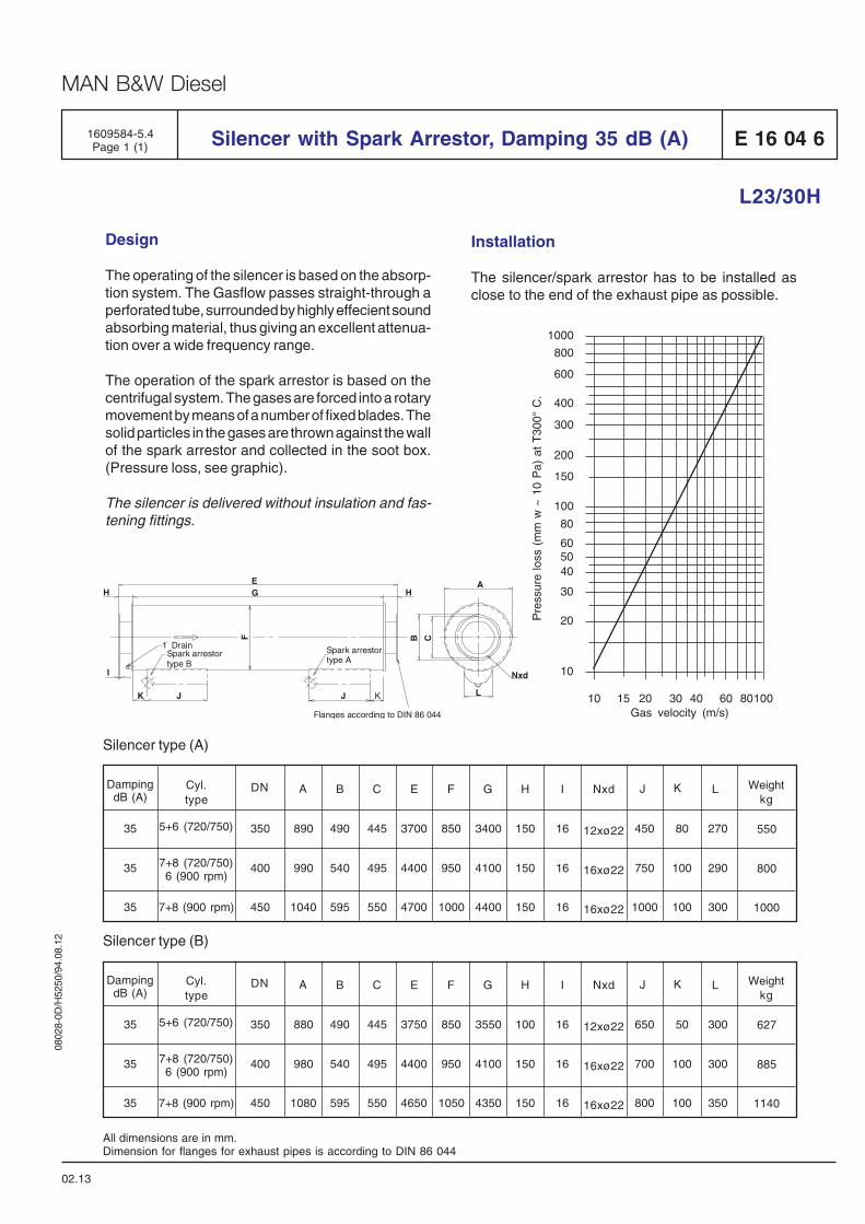
0802
8-0D
/H52
50/9
4.08
.12
MAN B&W Diesel
L23/30H
E 16 04 6Silencer with Spark Arrestor, Damping 35 dB (A)1609584-5.4Page 1 (1)
02.13
All dimensions are in mm.Dimension for flanges for exhaust pipes is according to DIN 86 044
Design
The operating of the silencer is based on the absorp-tion system. The Gasflow passes straight-through aperforated tube, surrounded by highly effecient soundabsorbing material, thus giving an excellent attenua-tion over a wide frequency range.
The operation of the spark arrestor is based on thecentrifugal system. The gases are forced into a rotarymovement by means of a number of fixed blades. Thesolid particles in the gases are thrown against the wallof the spark arrestor and collected in the soot box.(Pressure loss, see graphic).
The silencer is delivered without insulation and fas-tening fittings.
Silencer type (B)
Weightkg
NxdIHGFECBDN ACyl.type
DampingdB (A)
K LJ
35
35
35
350
400
450
890
990
1040
490
540
595
445
495
550
3700
4400
4700
850
950
1000
3400
4100
4400
150
150
150
16
16
16
12xø22
16xø22
16xø22
450
750
1000
80
100
100
270
290
300
550
800
1000
Silencer type (A)
7+8 (900 rpm)
600
800
300
200
150
100
80
605040
30
20
10
400
1000
10 15 20 30 40 60 80100Gas velocity (m/s)
Pre
ssur
e lo
ss (
mm
w ~
10
Pa)
at
T30
0° C
.
Installation
The silencer/spark arrestor has to be installed asclose to the end of the exhaust pipe as possible.
5+6 (720/750)
7+8 (720/750)6 (900 rpm)
Weightkg
NxdIHGFECBDN ACyl.type
DampingdB (A)
K LJ
35
35
35
350
400
450
880
980
1080
490
540
595
445
495
550
3750
4400
4650
850
950
1050
3550
4100
4350
100
150
150
16
16
16
12xø22
16xø22
16xø22
650
700
800
50
100
100
300
300
350
627
885
11407+8 (900 rpm)
5+6 (720/750)
7+8 (720/750)6 (900 rpm)
Flanges according to DIN 86 044
EGH
I
K J J K L
A
B CF
Spark arrestortype A
Spark arrestortype B
1 Drain
Nxd
H


Speed Control System
B 17

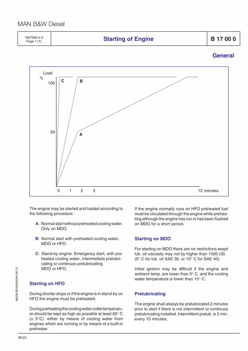
0802
8-0D
/H52
50/9
4.08
.12
MAN B&W Diesel
The engine may be started and loaded according tothe following procedure:
A: Normal start without preheated cooling water.Only on MDO.
B: Normal start with preheated cooling water.MDO or HFO.
C: Stand-by engine. Emergency start, with pre-heated cooling water, intermediate prelubri-cating or continuos prelubricating.MDO or HFO.
Starting on HFO
During shorter stops or if the engine is in stand-by onHFO the engine must be preheated.
During preheating the cooling water outlet temperatu-re should be kept as high as possible at least 60° C(± 5°C) -either by means of cooling water fromengines which are running or by means of a built-inpreheater.
If the engine normally runs on HFO preheated fuelmust be circulated through the engine while prehea-ting although the engine has run or has been flushedon MDO for a short period.
Starting on MDO
For starting on MDO there are no restrictions exeptlub. oil viscosity may not by higher than 1500 cSt.(0° C for lub. oil SAE 30, or 10° C for SAE 40).
Initial ignition may be difficult if the engine andambient temp. are lower than 0° C, and the coolingwater temperature is lower than 15° C.
Prelubricating
The engine shall always be prelubricated 2 minutesprior to start if there is not intermittent or continuosprelubricating installed. Intermittent prelub. is 2 min.every 10 minutes.
1607583-4.3Page 1 (1) Starting of Engine B 17 00 0
General
99.03
0 1 2 3 12 minutes
Load%
100
50 A
BC

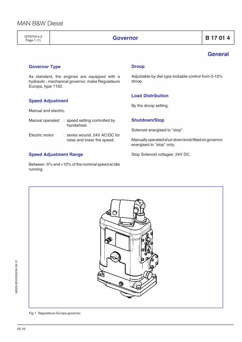
0802
8-0D
/H52
50/9
4.08
.12
MAN B&W Diesel
02.16
General
Governor Type
As standard, the engines are equipped with ahydraulic - mechanical governor, make RegulateursEuropa, type 1102.
Speed Adjustment
Manual and electric.
Manual operated : speed setting controlled byhandwheel.
Electric motor : series wound: 24V AC/DC forraise and lower the speed.
Speed Adjustment Range
Between -5% and +10% of the nominal speed at idlerunning.
1679743-4.2Page 1 (1) Governor B 17 01 4
Fig 1 Regulateurs Europa governor.
Droop
Adjustable by dial type lockable control from 0-10%droop.
Load Distribution
By the droop setting.
Shutdown/Stop
Solenoid energised to "stop".
Manually operated shut-down knob fitted on governorenergised to "stop" only.
Stop Solenoid voltages: 24V DC.

0802
8-0D
/H52
50/9
4.08
.12
MAN B&W Diesel
General
03.12
1683324-8.2Page 1 (2) CoCoS P 17 40 0
Description
The Computer Controlled Surveillance system is thefamily name of the software application productsfrom the MAN B&W Diesel group.
CoCoS comprises four individual software applicationproducts:
- CoCoS-EDS, Engine Diagnostics System- CoCoS-MPS, Maintenance Planning System- CoCoS-SPC, Spare Part Catalogue- CoCoS-SPO, Stock Handling and Spare Part
Ordering
CoCoS MPS, SPC, and SPO can communicate withone another, or they can be used as separate stand-alone system. These three applications can alsohandle non-MAN B&W Diesel technical equipment;for instance pumps and separators.
The objectives of the CoCos software products areto provide:
● Increased availability and reliability of engines.
● Efficient reduction of operating costs andlosses.
● Efficient planning of engine maintenance.
● Easy and unambiguous identification of spareparts.
● Integrated stock handling and spare partordering.
CoCoS-EDS (P 17 50 1, P 17 50 2)
Engine Diagnostics System, CoCoS-EDS assists inthe performance evaluation through diagnostics.Key features are: on-line data logging, monitoring,diagnostics and trends.
The main objectives of CoCoS-EDS are:
● To assist in decision making onboard, at theoffice, or at the power plant.
● To improve availability and reliability of engines.
● To reduce operating costs and losses due toengine failure.
These objectives are achieved through:
● Logging, monitoring and storage of operatingdata.
● Unambiguous diagnostics of operating states.
● Timely detection of irregularities.
To obtain the full benefits of the principal features ofCoCoS-EDS, it should have on-line connections tothe alarm system and other data acquisition sy-stems. However, manual input facilities make itpossible to utilise CoCoS-EDS for off-line equipment,too.
CoCoS-MPS (P 17 60 1, P 17 60 2)
Maintenance Planning System, CoCoS-MPS assistsin the planning and initiating of preventivemaintenance. Key features are: scheduling ofinspections and overhaul, forecasting and budgetingof spare part requirements, estimating of the amountof work hours needed, work procedures, and loggingof maintenance history.
The main objectives of CoCoS-MPS are:
● To assist in decision making onboard or at thepower plant.
● To improve availability and reliability of engines.
● To reduce maintenance costs and losses.
0802
8-0D
/H52
50/9
4.08
.12
MAN B&W Diesel
General
03.12
1683324-8.2Page 2 (2)CoCoSP 17 40 0
These objectives are achieved through:
● Comprehensive maintenance programmes.
● Dedicated tools for extensive planning of engineperformance.
● Forecasting of the consumption of spare partsand work hours.
● Logging of maintenance history andexperience.
CoCoS-MPS can be used as a stand-alone system.However, to obtain the full benefits of the principalfeatures of CoCoS-MPS, it should have directaccess to CoCoS-SPC and CoCoS-SPO.
CoCoS-SPC (P 17 70 1, P 17 70 2)
Spare Part Catalogue, CoCoS-SPC assists in theidentification of spare part. Key features are: multi-level part lists, spare part information, and graphics.
The main objectives of CoCoS-MPS are:
● To assist in the identification of spare parts forengines and other technical equipment, on-board or at the power plant.
● To give easy access to spare part information.
These objectives are achieved through:
● Multilevel part lists.
● Graphics.
● Spare part information.
● Extended search.
CoCoS-SPC can be used as a stand-alone system.However, to obtain the full benefits of the features ofCoCoS-SPC, it should have direct access toCoCoS-MPS and CoCoS-SPO.
CoCoS-SPO (P 17 80 1, P 17 80 2)
Stock Handling and Spare Part Ordering, CoCoS-SPO assists in managing the procurement and controlof the spare part stock. Key features are: availablestock, store location, planned receipts and issues,minimum stock, safety stock, suppliers, prices andstatistics.
The main objectives of CoCoS-SPO are:
● To assist in the handling of the spare partstock.
● To give up-to-date information on current stock.
● To forecast spare part availability.
● To assist in the procurement of spare parts.
These objectives are achieved through:
● Stock administration.
● Automatic generation of ordering proposals.
● Easy preparation of - and follow-up on - orders.
● Extensive reporting.
CoCoS-SPO can be used as a stand-alone system.However, to obtain the full benefits of the integratedstock handling and spare part ordering, and of theother principal features of CoCoS-SPO, it shouldhave direct access to CoCoS-MPS and CoCoS-SPC.
CoCoS Suite (P 17 90 1)
CoCoS Suite includes the four above-mentionedsystem;P 17 50 1 (2), P 17 60 1 (2), P 17 70 1 (2) andP 17 80 1 (2).

Monitoring Equipment
B 18

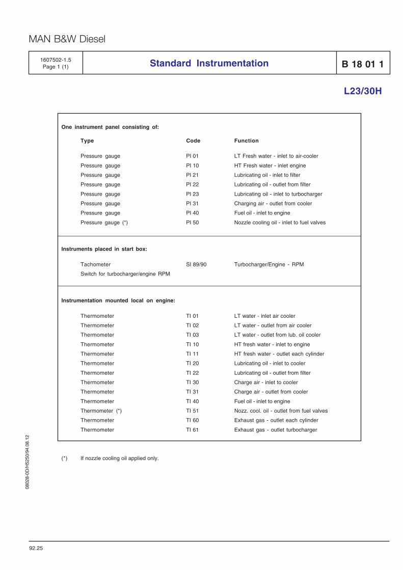
0802
8-0D
/H52
50/9
4.08
.12
MAN B&W Diesel
Standard Instrumentation1607502-1.5Page 1 (1) B 18 01 1
L23/30H
92.25
One instrument panel consisting of:
Type Code Function
Pressure gauge PI 01 LT Fresh water - inlet to air-cooler
Pressure gauge PI 10 HT Fresh water - inlet engine
Pressure gauge PI 21 Lubricating oil - inlet to filter
Pressure gauge PI 22 Lubricating oil - outlet from filter
Pressure gauge PI 23 Lubricating oil - inlet to turbocharger
Pressure gauge PI 31 Charging air - outlet from cooler
Pressure gauge PI 40 Fuel oil - inlet to engine
Pressure gauge (*) PI 50 Nozzle cooling oil - inlet to fuel valves
Instruments placed in start box:
Tachometer SI 89/90 Turbocharger/Engine - RPM
Switch for turbocharger/engine RPM
Instrumentation mounted local on engine:
Thermometer TI 01 LT water - inlet air cooler
Thermometer TI 02 LT water - outlet from air cooler
Thermometer TI 03 LT water - outlet from lub. oil cooler
Thermometer TI 10 HT fresh water - inlet to engine
Thermometer TI 11 HT fresh water - outlet each cylinder
Thermometer TI 20 Lubricating oil - inlet to cooler
Thermometer TI 22 Lubricating oil - outlet from filter
Thermometer TI 30 Charge air - inlet to cooler
Thermometer TI 31 Charge air - outlet from cooler
Thermometer TI 40 Fuel oil - inlet to engine
Thermometer (*) TI 51 Nozz. cool. oil - outlet from fuel valves
Thermometer TI 60 Exhaust gas - outlet each cylinder
Thermometer TI 61 Exhaust gas - outlet turbocharger
(*) If nozzle cooling oil applied only.

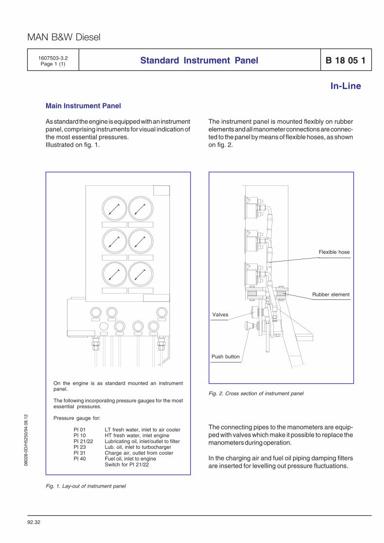
0802
8-0D
/H52
50/9
4.08
.12
MAN B&W Diesel
On the engine is as standard mounted an instrumentpanel.
The following incorporating pressure gauges for the mostessential pressures.
Pressure gauge for:
PI 01 LT fresh water, inlet to air coolerPI 10 HT fresh water, inlet enginePI 21/22 Lubricating oil, inlet/outlet to filterPI 23 Lub. oil, inlet to turbochargerPI 31 Charge air, outlet from coolerPI 40 Fuel oil, inlet to engine
Switch for PI 21/22
1607503-3.2Page 1 (1) Standard Instrument Panel B 18 05 1
In-Line
Main Instrument Panel
As standard the engine is equipped with an instrumentpanel, comprising instruments for visual indication ofthe most essential pressures.Illustrated on fig. 1.
92.32
The instrument panel is mounted flexibly on rubberelements and all manometer connections are connec-ted to the panel by means of flexible hoses, as shownon fig. 2.
Push button
Valves
Flexible hose
Rubber element
Fig. 2. Cross section of instrument panel
The connecting pipes to the manometers are equip-ped with valves which make it possible to replace themanometers during operation.
In the charging air and fuel oil piping damping filtersare inserted for levelling out pressure fluctuations.
Fig. 1. Lay-out of instrument panel


Safety and Control System
B 19

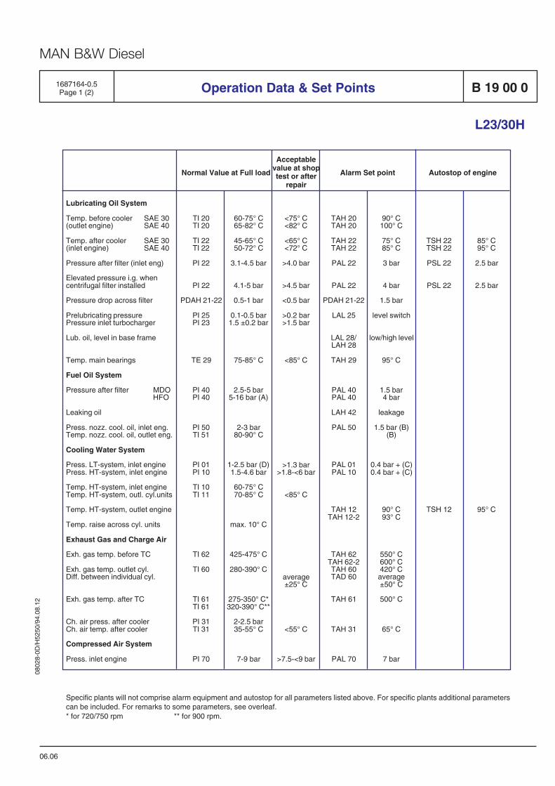
0802
8-0D
/H52
50/9
4.08
.12
MAN B&W Diesel
Normal Value at Full load Alarm Set point Autostop of engine
90° C100° C
75° C85° C
3 bar
4 bar
1.5 bar
level switch
low/high level
95° C
1.5 bar4 bar
leakage
1.5 bar (B)(B)
0.4 bar + (C)0.4 bar + (C)
90° C93° C
550° C600° C420° Caverage±50° C
500° C
65° C
7 bar
Operation Data & Set Points
L23/30H
B 19 00 0
06.06
1687164-0.5Page 1 (2)
Lubricating Oil System
Temp. before cooler SAE 30(outlet engine) SAE 40
Temp. after cooler SAE 30(inlet engine) SAE 40
Pressure after filter (inlet eng)
Elevated pressure i.g. whencentrifugal filter installed
Pressure drop across filter
Prelubricating pressurePressure inlet turbocharger
Lub. oil, level in base frame
Temp. main bearings
Fuel Oil System
Pressure after filter MDOHFO
Leaking oil
Press. nozz. cool. oil, inlet eng.Temp. nozz. cool. oil, outlet eng.
Cooling Water System
Press. LT-system, inlet enginePress. HT-system, inlet engine
Temp. HT-system, inlet engineTemp. HT-system, outl. cyl.units
Temp. HT-system, outlet engine
Temp. raise across cyl. units
Exhaust Gas and Charge Air
Exh. gas temp. before TC
Exh. gas temp. outlet cyl.Diff. between individual cyl.
Exh. gas temp. after TC
Ch. air press. after coolerCh. air temp. after cooler
Compressed Air System
Press. inlet engine
TI 20TI 20
TI 22TI 22
PI 22
PI 22
PDAH 21-22
PI 25PI 23
TE 29
PI 40PI 40
PI 50TI 51
PI 01PI 10
TI 10TI 11
TI 62
TI 60
TI 61TI 61
PI 31TI 31
PI 70
60-75° C65-82° C
45-65° C50-72° C
3.1-4.5 bar
4.1-5 bar
0.5-1 bar
0.1-0.5 bar1.5 ±0.2 bar
75-85° C
2.5-5 bar5-16 bar (A)
2-3 bar80-90° C
1-2.5 bar (D)1.5-4.6 bar
60-75° C70-85° C
max. 10° C
425-475° C
280-390° C
275-350° C*320-390° C**
2-2.5 bar35-55° C
7-9 bar
TAH 20TAH 20
TAH 22TAH 22
PAL 22
PAL 22
PDAH 21-22
LAL 25
LAL 28/LAH 28
TAH 29
PAL 40PAL 40
LAH 42
PAL 50
PAL 01PAL 10
TAH 12TAH 12-2
TAH 62TAH 62-2TAH 60TAD 60
TAH 61
TAH 31
PAL 70
TSH 22TSH 22
PSL 22
PSL 22
TSH 12
85° C95° C
2.5 bar
2.5 bar
95° C
Specific plants will not comprise alarm equipment and autostop for all parameters listed above. For specific plants additional parameterscan be included. For remarks to some parameters, see overleaf.* for 720/750 rpm ** for 900 rpm.
Acceptablevalue at shoptest or after
repair
<75° C<82° C
<65° C<72° C
>4.0 bar
>4.5 bar
<0.5 bar
>0.2 bar>1.5 bar
<85° C
>1.3 bar>1.8-<6 bar
<85° C
average±25° C
<55° C
>7.5-<9 bar
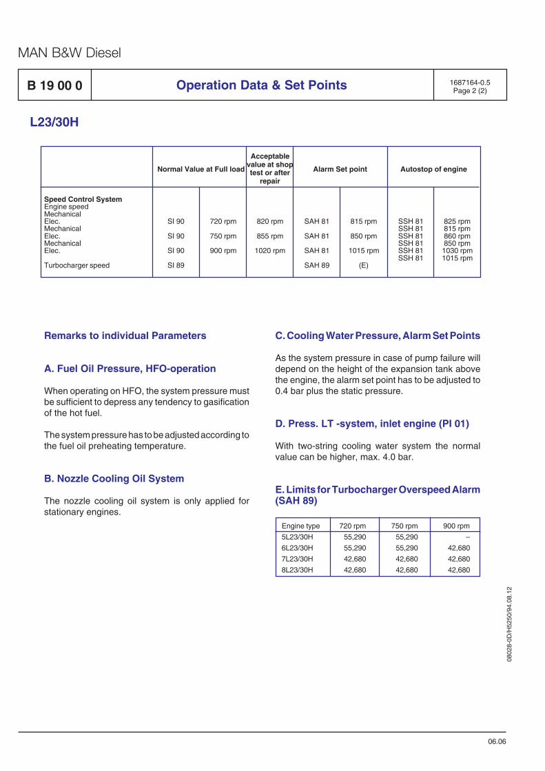
0802
8-0D
/H52
50/9
4.08
.12
MAN B&W Diesel
Operation Data & Set Points
C. Cooling Water Pressure, Alarm Set Points
As the system pressure in case of pump failure willdepend on the height of the expansion tank abovethe engine, the alarm set point has to be adjusted to0.4 bar plus the static pressure.
D. Press. LT -system, inlet engine (PI 01)
With two-string cooling water system the normalvalue can be higher, max. 4.0 bar.
E. Limits for Turbocharger Overspeed Alarm(SAH 89)
B 19 00 0
Remarks to individual Parameters
A. Fuel Oil Pressure, HFO-operation
When operating on HFO, the system pressure mustbe sufficient to depress any tendency to gasificationof the hot fuel.
The system pressure has to be adjusted according tothe fuel oil preheating temperature.
B. Nozzle Cooling Oil System
The nozzle cooling oil system is only applied forstationary engines.
L23/30H
06.06
1687164-0.5Page 2 (2)
Engine type 720 rpm 750 rpm 900 rpm
5L23/30H 55,290 55,290 –
6L23/30H 55,290 55,290 42,680
7L23/30H 42,680 42,680 42,680
8L23/30H 42,680 42,680 42,680
Normal Value at Full load Alarm Set point Autostop of engine
Acceptablevalue at shoptest or after
repair
Speed Control SystemEngine speedMechanicalElec.MechanicalElec.MechanicalElec.
Turbocharger speed
SI 90
SI 90
SI 90
SI 89
720 rpm
750 rpm
900 rpm
SAH 81
SAH 81
SAH 81
SAH 89
815 rpm
850 rpm
1015 rpm
(E)
SSH 81SSH 81SSH 81SSH 81SSH 81SSH 81
825 rpm815 rpm860 rpm850 rpm1030 rpm1015 rpm
820 rpm
855 rpm
1020 rpm
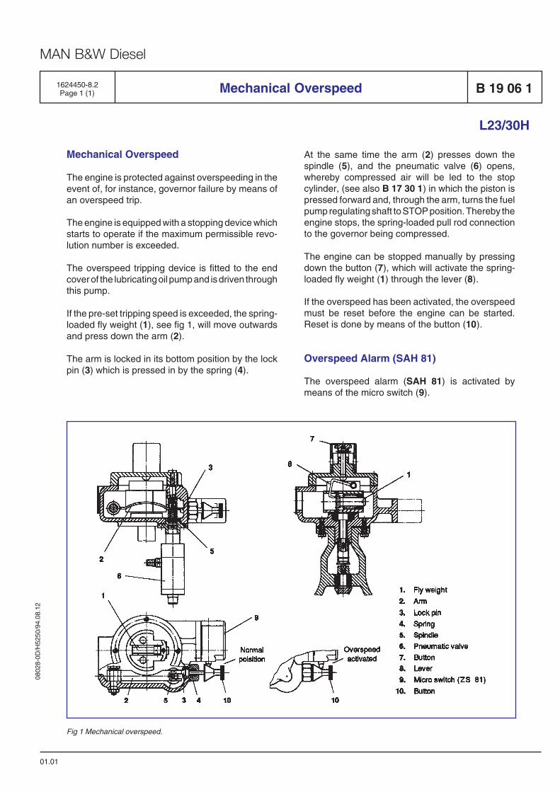
0802
8-0D
/H52
50/9
4.08
.12
MAN B&W Diesel
Mechanical Overspeed
01.01
L23/30H
1624450-8.2Page 1 (1)
Mechanical Overspeed
The engine is protected against overspeeding in theevent of, for instance, governor failure by means ofan overspeed trip.
The engine is equipped with a stopping device whichstarts to operate if the maximum permissible revo-lution number is exceeded.
The overspeed tripping device is fitted to the endcover of the lubricating oil pump and is driven throughthis pump.
If the pre-set tripping speed is exceeded, the spring-loaded fly weight (1), see fig 1, will move outwardsand press down the arm (2).
The arm is locked in its bottom position by the lockpin (3) which is pressed in by the spring (4).
B 19 06 1
Fig 1 Mechanical overspeed.
At the same time the arm (2) presses down thespindle (5), and the pneumatic valve (6) opens,whereby compressed air will be led to the stopcylinder, (see also B 17 30 1) in which the piston ispressed forward and, through the arm, turns the fuelpump regulating shaft to STOP position. Thereby theengine stops, the spring-loaded pull rod connectionto the governor being compressed.
The engine can be stopped manually by pressingdown the button (7), which will activate the spring-loaded fly weight (1) through the lever (8).
If the overspeed has been activated, the overspeedmust be reset before the engine can be started.Reset is done by means of the button (10).
Overspeed Alarm (SAH 81)
The overspeed alarm (SAH 81) is activated bymeans of the micro switch (9).

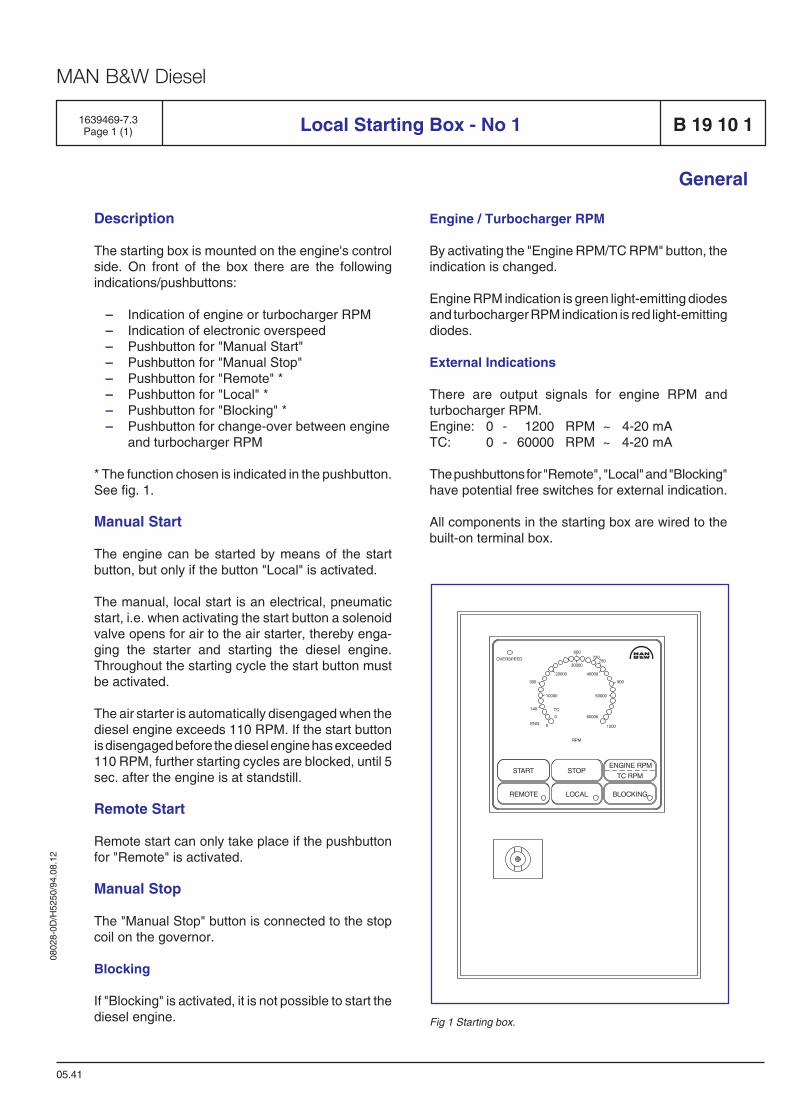
0802
8-0D
/H52
50/9
4.08
.12
MAN B&W Diesel
Description
The starting box is mounted on the engine's controlside. On front of the box there are the followingindications/pushbuttons:
– Indication of engine or turbocharger RPM– Indication of electronic overspeed– Pushbutton for "Manual Start"– Pushbutton for "Manual Stop"– Pushbutton for "Remote" *– Pushbutton for "Local" *– Pushbutton for "Blocking" *– Pushbutton for change-over between engine
and turbocharger RPM
* The function chosen is indicated in the pushbutton.See fig. 1.
Manual Start
The engine can be started by means of the startbutton, but only if the button "Local" is activated.
The manual, local start is an electrical, pneumaticstart, i.e. when activating the start button a solenoidvalve opens for air to the air starter, thereby enga-ging the starter and starting the diesel engine.Throughout the starting cycle the start button mustbe activated.
The air starter is automatically disengaged when thediesel engine exceeds 110 RPM. If the start buttonis disengaged before the diesel engine has exceeded110 RPM, further starting cycles are blocked, until 5sec. after the engine is at standstill.
Remote Start
Remote start can only take place if the pushbuttonfor "Remote" is activated.
Manual Stop
The "Manual Stop" button is connected to the stopcoil on the governor.
Blocking
If "Blocking" is activated, it is not possible to start thediesel engine.
1639469-7.3Page 1 (1) Local Starting Box - No 1 B 19 10 1
05.41
Engine / Turbocharger RPM
By activating the "Engine RPM/TC RPM" button, theindication is changed.
Engine RPM indication is green light-emitting diodesand turbocharger RPM indication is red light-emittingdiodes.
External Indications
There are output signals for engine RPM andturbocharger RPM.Engine: 0 - 1200 RPM ~ 4-20 mATC: 0 - 60000 RPM ~ 4-20 mA
The pushbuttons for "Remote", "Local" and "Blocking"have potential free switches for external indication.
All components in the starting box are wired to thebuilt-on terminal box.
General
Fig 1 Starting box.

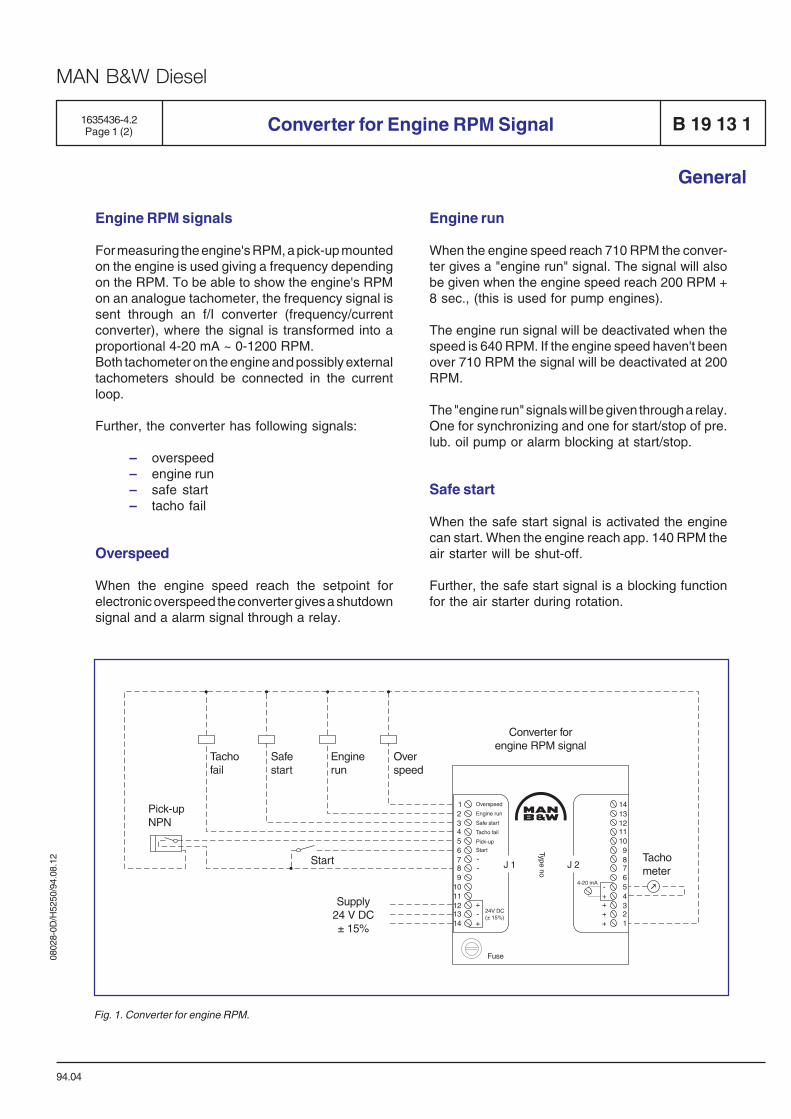
0802
8-0D
/H52
50/9
4.08
.12
MAN B&W Diesel
1635436-4.2Page 1 (2) Converter for Engine RPM Signal B 19 13 1
General
Engine RPM signals
For measuring the engine's RPM, a pick-up mountedon the engine is used giving a frequency dependingon the RPM. To be able to show the engine's RPMon an analogue tachometer, the frequency signal issent through an f/I converter (frequency/currentconverter), where the signal is transformed into aproportional 4-20 mA ~ 0-1200 RPM.Both tachometer on the engine and possibly externaltachometers should be connected in the currentloop.
Further, the converter has following signals:
– overspeed– engine run– safe start– tacho fail
Overspeed
When the engine speed reach the setpoint forelectronic overspeed the converter gives a shutdownsignal and a alarm signal through a relay.
94.04
Engine run
When the engine speed reach 710 RPM the conver-ter gives a "engine run" signal. The signal will alsobe given when the engine speed reach 200 RPM +8 sec., (this is used for pump engines).
The engine run signal will be deactivated when thespeed is 640 RPM. If the engine speed haven't beenover 710 RPM the signal will be deactivated at 200RPM.
The "engine run" signals will be given through a relay.One for synchronizing and one for start/stop of pre.lub. oil pump or alarm blocking at start/stop.
Safe start
When the safe start signal is activated the enginecan start. When the engine reach app. 140 RPM theair starter will be shut-off.
Further, the safe start signal is a blocking functionfor the air starter during rotation.
Fig. 1. Converter for engine RPM.

0802
8-0D
/H52
50/9
4.08
.12
MAN B&W Diesel
B 19 13 1
Tacho fail
The tacho fail signal will be on when everything isnormal. If the pick-up or the converter failed thesignal will be deactivated. E.g. if there is powersupply failure.
The converter for engine RPM signal is mounted inthe terminal box on the engine.
Pick-up
The pick-up is a NPN-type with LED-indication. Thesensing distance is 0.5 to 1.2 mm.
All wiring to relay, pick-up and tachometer are madeby MAN B&W, Holeby.
Data
Operating data : 24 V DC ± 15%Power consumption : 3 WattAmbient temperature : -20° C to 70° COutput current : 4-20 mA ~ 0-1200 RPM
Converter for Engine RPM Signal
General
94.04
1635436-4.2Page 2 (2)
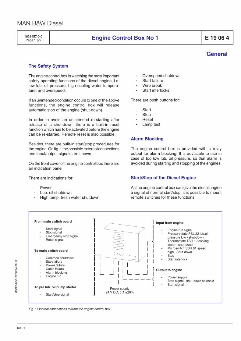
0802
8-0D
/H52
50/9
4.08
.12
MAN B&W Diesel
⎫⎫⎫⎫⎫⎪⎪⎪⎪⎪⎪⎪⎪⎪⎪⎪⎪⎪⎪⎪⎪⎪⎪⎪⎪⎪⎪⎪⎪⎪⎪⎪⎪⎪⎪⎬⎬⎬⎬⎬⎪⎪⎪⎪⎪⎪⎪⎪⎪⎪⎪⎪⎪⎪⎪⎪⎪⎪⎪⎪⎪⎪⎪⎪⎪⎪⎪⎪⎪⎪⎪⎪⎪⎪⎪⎭⎭⎭⎭⎭
1631457-0.0Page 1 (2) Engine Control Box No 1 E 19 06 4
General
The Safety System
The engine control box is watching the most importantsafety operating functions of the diesel engine, i.e.low lub. oil pressure, high cooling water tempera-ture, and overspeed.
If an unintended condition occurs to one of the abovefunctions, the engine control box will releaseautomatic stop of the engine (shut-down).
In order to avoid an unintended re-starting afterrelease of a shut-down, there is a built-in resetfunction which has to be activated before the enginecan be re-started. Remote reset is also possible.
Besides, there are built-in start/stop procedures forthe engine. On fig. 1 the possible external connectionsand input/output signals are shown.
On the front cover of the engine control box there arean indication panel.
There are indications for:
- Power- Lub. oil shutdown- High temp. fresh water shutdown
00.01
⎧⎧⎧⎧⎧⎪⎪⎪⎪⎪⎨⎨⎨⎨⎨⎩⎩⎩⎩⎩
Power supply24 V DC, 6 A ±20%
Input from engine
- Engine run signal- Pressurestate PSL 22 lub.oil
pressure low - shut-down- Thermostate TSH 12 cooling
water - shut-down- Microswitch SSH 81 speed
high - Shut-down- Stop- Start interlock
⎧⎧⎧⎧⎧⎪⎪⎪⎪⎪⎪⎪⎪⎪⎪⎪⎪⎪⎪⎪⎨⎨⎨⎨⎨⎪⎪⎪⎪⎪⎪⎪⎪⎪⎪⎪⎪⎪⎪⎪⎩⎩⎩⎩⎩
Output to engine
- Power supply- Stop signal - shut-down solenoid- Start signal
Fig 1 External connections to/from the engine control box .
- Overspeed shutdown- Start failure- Wire break- Start interlocks
There are push buttons for:
- Start- Stop- Reset- Lamp test
Alarm Blocking
The engine control box is provided with a relayoutput for alarm blocking. It is advisable to use incase of too low lub. oil pressure, so that alarm isavoided during starting and stopping of the engines.
Start/Stop of the Diesel Engine
As the engine control box can give the diesel enginea signal of normal start/stop, it is possible to mountremote switches for these functions.
From main switch board
- Start signal- Stop signal- Emergency stop signal- Reset signal
To main switch board
- Common shutdown- Start failure- Power failure- Cable failure- Alarm blocking- Engine run
To pre.lub. oil pump starter
- Start/stop signal
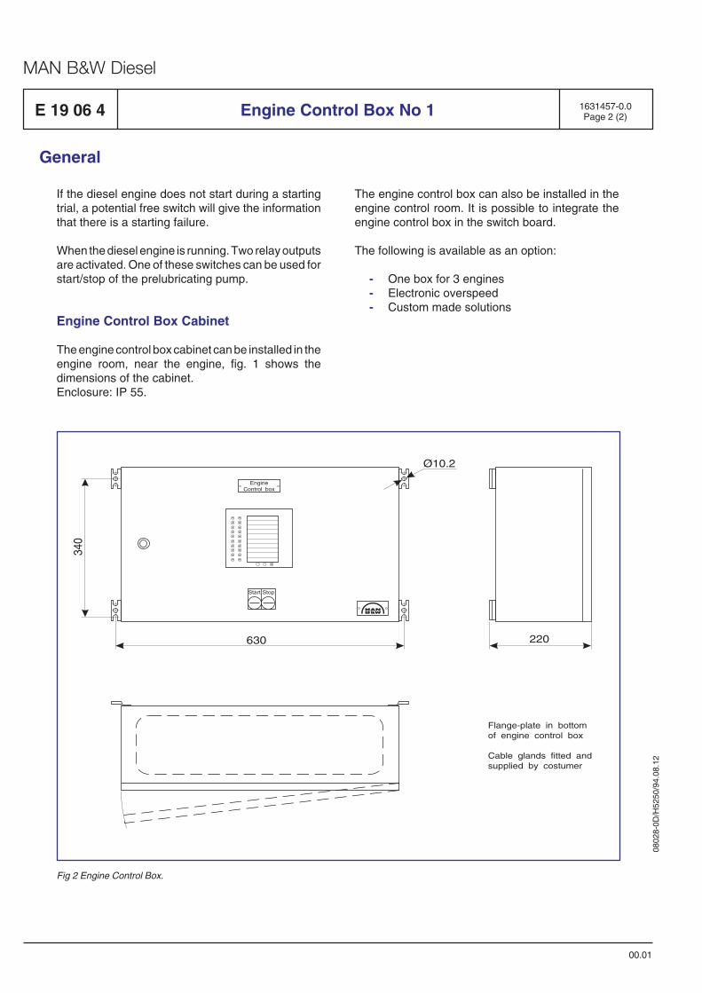
0802
8-0D
/H52
50/9
4.08
.12
MAN B&W Diesel
E 19 06 4
If the diesel engine does not start during a startingtrial, a potential free switch will give the informationthat there is a starting failure.
When the diesel engine is running. Two relay outputsare activated. One of these switches can be used forstart/stop of the prelubricating pump.
Engine Control Box Cabinet
The engine control box cabinet can be installed in theengine room, near the engine, fig. 1 shows thedimensions of the cabinet.Enclosure: IP 55.
1631457-0.0Page 2 (2)Engine Control Box No 1
00.01
General
The engine control box can also be installed in theengine control room. It is possible to integrate theengine control box in the switch board.
The following is available as an option:
- One box for 3 engines- Electronic overspeed- Custom made solutions
EngineControl box
Start Stop
340
630
Ø10.2
220
Flange-plate in bottomof engine control box
Cable glands fitted andsupplied by costumer
Fig 2 Engine Control Box.
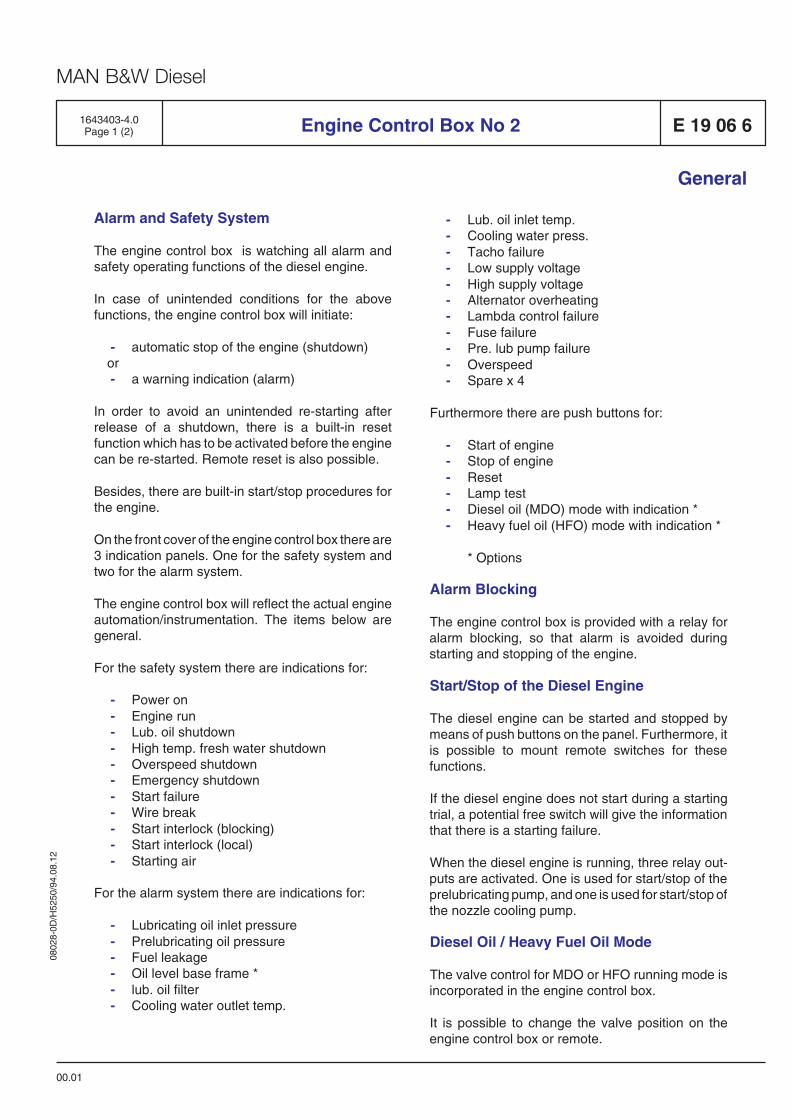
0802
8-0D
/H52
50/9
4.08
.12
MAN B&W Diesel
Engine Control Box No 2 E 19 06 6
General
Alarm and Safety System
The engine control box is watching all alarm andsafety operating functions of the diesel engine.
In case of unintended conditions for the abovefunctions, the engine control box will initiate:
- automatic stop of the engine (shutdown)or- a warning indication (alarm)
In order to avoid an unintended re-starting afterrelease of a shutdown, there is a built-in resetfunction which has to be activated before the enginecan be re-started. Remote reset is also possible.
Besides, there are built-in start/stop procedures forthe engine.
On the front cover of the engine control box there are3 indication panels. One for the safety system andtwo for the alarm system.
The engine control box will reflect the actual engineautomation/instrumentation. The items below aregeneral.
For the safety system there are indications for:
- Power on- Engine run- Lub. oil shutdown- High temp. fresh water shutdown- Overspeed shutdown- Emergency shutdown- Start failure- Wire break- Start interlock (blocking)- Start interlock (local)- Starting air
For the alarm system there are indications for:
- Lubricating oil inlet pressure- Prelubricating oil pressure- Fuel leakage- Oil level base frame *- lub. oil filter- Cooling water outlet temp.
00.01
- Lub. oil inlet temp.- Cooling water press.- Tacho failure- Low supply voltage- High supply voltage- Alternator overheating- Lambda control failure- Fuse failure- Pre. lub pump failure- Overspeed- Spare x 4
Furthermore there are push buttons for:
- Start of engine- Stop of engine- Reset- Lamp test- Diesel oil (MDO) mode with indication *- Heavy fuel oil (HFO) mode with indication *
* Options
Alarm Blocking
The engine control box is provided with a relay foralarm blocking, so that alarm is avoided duringstarting and stopping of the engine.
Start/Stop of the Diesel Engine
The diesel engine can be started and stopped bymeans of push buttons on the panel. Furthermore, itis possible to mount remote switches for thesefunctions.
If the diesel engine does not start during a startingtrial, a potential free switch will give the informationthat there is a starting failure.
When the diesel engine is running, three relay out-puts are activated. One is used for start/stop of theprelubricating pump, and one is used for start/stop ofthe nozzle cooling pump.
Diesel Oil / Heavy Fuel Oil Mode
The valve control for MDO or HFO running mode isincorporated in the engine control box.
It is possible to change the valve position on theengine control box or remote.
1643403-4.0Page 1 (2)
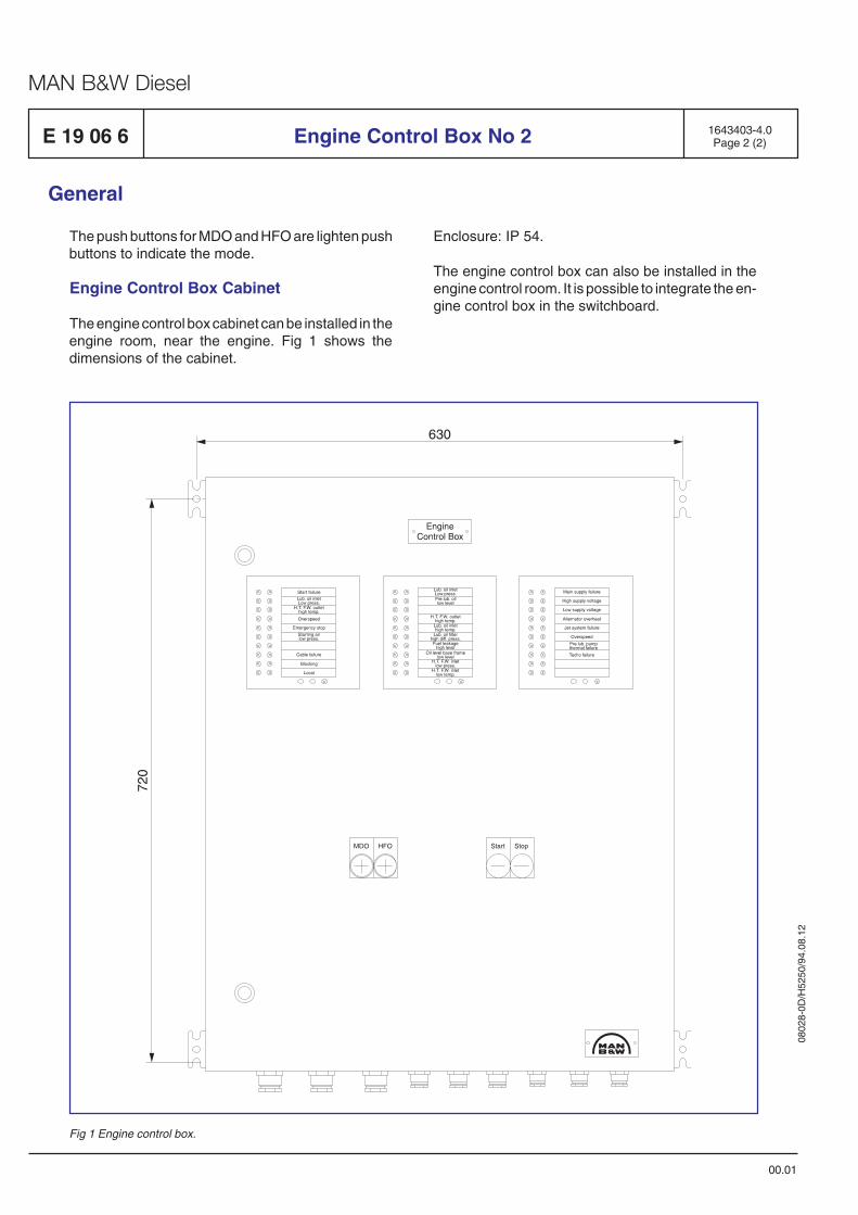
0802
8-0D
/H52
50/9
4.08
.12
MAN B&W Diesel
E 19 06 6 Engine Control Box No 2
00.01
General
1643403-4.0Page 2 (2)
Fig 1 Engine control box.
The push buttons for MDO and HFO are lighten pushbuttons to indicate the mode.
Engine Control Box Cabinet
The engine control box cabinet can be installed in theengine room, near the engine. Fig 1 shows thedimensions of the cabinet.
Enclosure: IP 54.
The engine control box can also be installed in theengine control room. It is possible to integrate the en-gine control box in the switchboard.
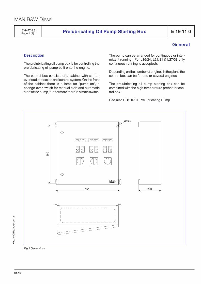
0802
8-0D
/H52
50/9
4.08
.12
MAN B&W Diesel
1631477-3.3Page 1 (2) Prelubricating Oil Pump Starting Box E 19 11 0
General
01.10
Description
The prelubricating oil pump box is for controlling theprelubricating oil pump built onto the engine.
The control box consists of a cabinet with starter,overload protection and control system. On the frontof the cabinet there is a lamp for "pump on", achange-over switch for manual start and automaticstart of the pump, furthermore there is a main switch.
The pump can be arranged for continuous or inter-mittent running. (For L16/24, L21/31 & L27/38 onlycontinuous running is accepted).
Depending on the number of engines in the plant, thecontrol box can be for one or several engines.
The prelubricating oil pump starting box can becombined with the high temperature preheater con-trol box.
See also B 12 07 0, Prelubricating Pump.
Pre.lub. oil pumpEngine 2
Pre.lub. oil pumpEngine 1
Pre.lub. oil pumpEngine 3
560
630
Ø10.2
220
PumpON
Man AutoOFF
PumpON
Man AutoOFF
PumpON
Man AutoOFF
Fig 1 Dimensions.
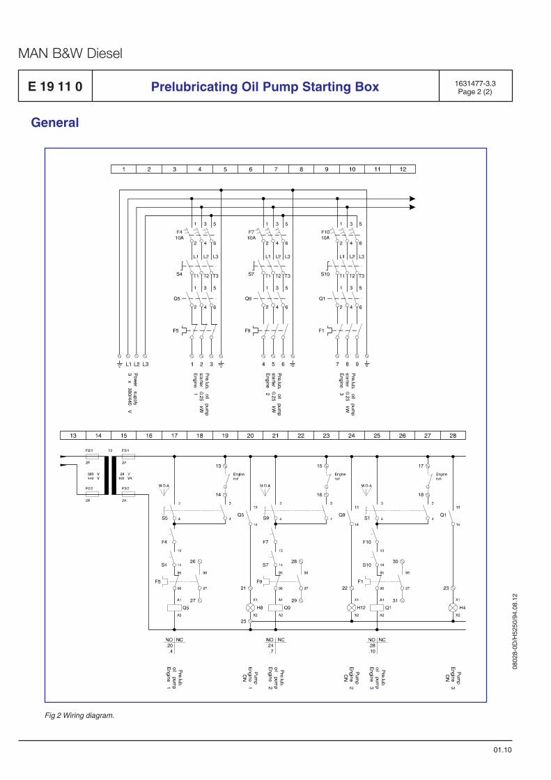
0802
8-0D
/H52
50/9
4.08
.12
MAN B&W Diesel
E 19 11 0 1631477-3.3Page 2 (2)Prelubricating Oil Pump Starting Box
General
01.10
Fig 2 Wiring diagram.
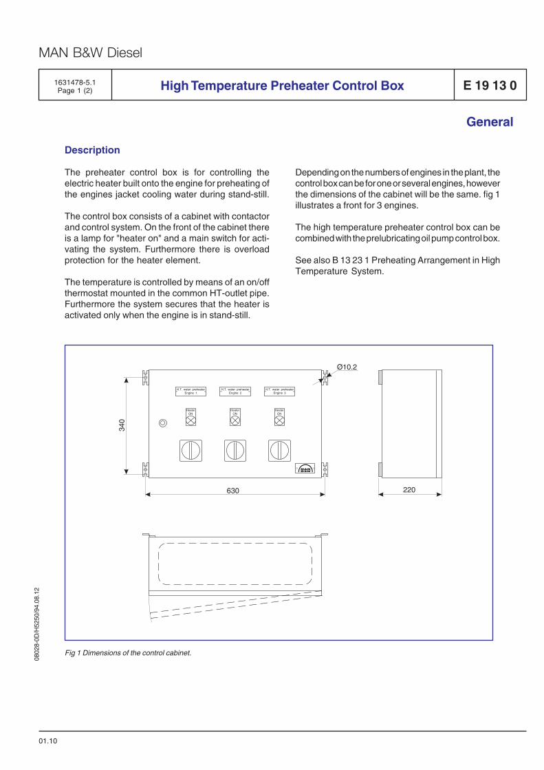
0802
8-0D
/H52
50/9
4.08
.12
MAN B&W Diesel
1631478-5.1Page 1 (2) High Temperature Preheater Control Box E 19 13 0
General
01.10
Description
The preheater control box is for controlling theelectric heater built onto the engine for preheating ofthe engines jacket cooling water during stand-still.
The control box consists of a cabinet with contactorand control system. On the front of the cabinet thereis a lamp for "heater on" and a main switch for acti-vating the system. Furthermore there is overloadprotection for the heater element.
The temperature is controlled by means of an on/offthermostat mounted in the common HT-outlet pipe.Furthermore the system secures that the heater isactivated only when the engine is in stand-still.
Depending on the numbers of engines in the plant, thecontrol box can be for one or several engines, howeverthe dimensions of the cabinet will be the same. fig 1illustrates a front for 3 engines.
The high temperature preheater control box can becombined with the prelubricating oil pump control box.
See also B 13 23 1 Preheating Arrangement in HighTemperature System.
H.T. water preheaterEngine 2
H.T. water preheaterEngine 1
H.T. water preheaterEngine 3
340
630
Ø10.2
220
HeaterON
HeaterON
HeaterON
Fig 1 Dimensions of the control cabinet.
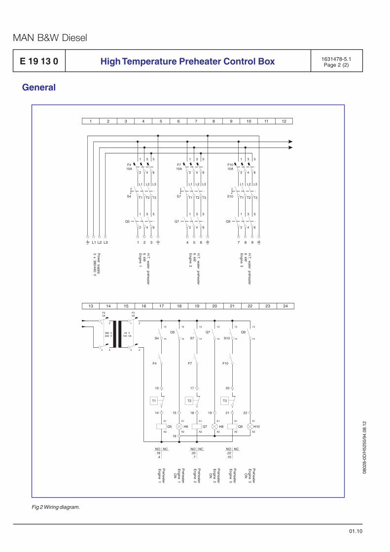
0802
8-0D
/H52
50/9
4.08
.12
MAN B&W Diesel
E 19 13 0 1631478-5.1Page 2 (2)High Temperature Preheater Control Box
General
01.10
Fig 2 Wiring diagram.
1 2 3 4 5 6 7 8 9 10 11 12
1 1 1
1 1 1
L1 L1 L1
2 2 2
2 2 2
T1 T1 T1
3 3 3
3 3 3
L2 L2 L2
4 4 4
4 4 4
T2 T2 T2
5 5 5
5 5 5
L3 L3 L3
6 6 6
6 6 6
T3 T3 T3
F410A
F710A
F1010A
Q5 Q7 Q9
S4 S7 S10
L1 1 4 7L2 2 5 8L3 3 6 9
H.T.
water
preheater6
kWE
ngine2
H.T.
water
preheater6
kWE
ngine1
Pow
ersupply
3x
380/440V
H.T.
water
preheater6
kWE
ngine3
13 14 15 16 17 18 19 20 21 22 23 24
13 13 13 1313 13
14
2
4
2
4
1
24 V100 VA
380 V440 V
3
1
3
14 14 1414 14
A1 X1 X1 X1A1 A1
A2 X2 X2 X2A2 A2
S4
F32A
F22A
Q5 Q7 Q9
S7 S10
13 17 20
14 15 19 22
16
NO.18
.4
NC NO.20
.7
NC NO.22.10
NC
18 21
Q5 H6 H8 H10Q7 Q9
T1 T2 T3
F4 F7 F10
Preheater
Engine
3O
N
Preheater
Engine
3
Preheater
Engine
2
Preheater
Engine
1
Preheater
Engine
2O
N
Preheater
Engine
1O
N

Foundation
B 20

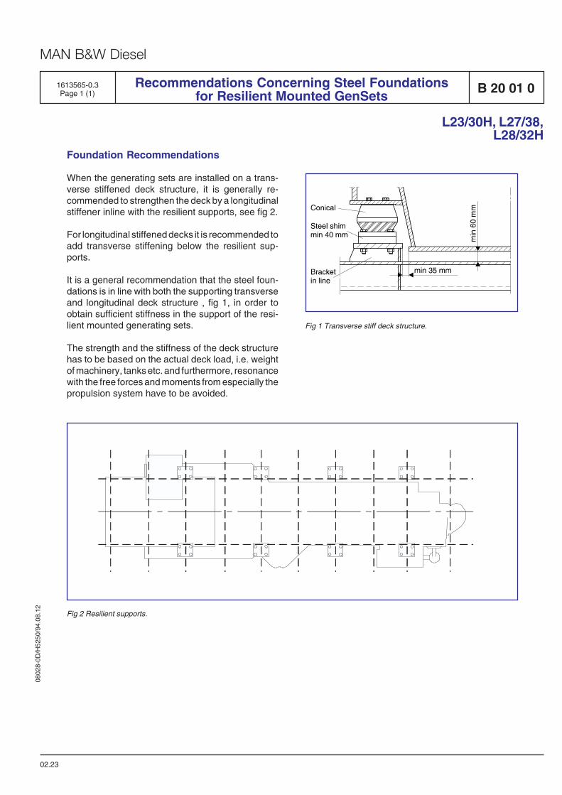
0802
8-0D
/H52
50/9
4.08
.12
MAN B&W Diesel
02.23
L23/30H, L27/38,L28/32H
B 20 01 01613565-0.3Page 1 (1)
Recommendations Concerning Steel Foundationsfor Resilient Mounted GenSets
Fig 2 Resilient supports.
Fig 1 Transverse stiff deck structure.
Foundation Recommendations
When the generating sets are installed on a trans-verse stiffened deck structure, it is generally re-commended to strengthen the deck by a longitudinalstiffener inline with the resilient supports, see fig 2.
For longitudinal stiffened decks it is recommended toadd transverse stiffening below the resilient sup-ports.
It is a general recommendation that the steel foun-dations is in line with both the supporting transverseand longitudinal deck structure , fig 1, in order toobtain sufficient stiffness in the support of the resi-lient mounted generating sets.
The strength and the stiffness of the deck structurehas to be based on the actual deck load, i.e. weightof machinery, tanks etc. and furthermore, resonancewith the free forces and moments from especially thepropulsion system have to be avoided.

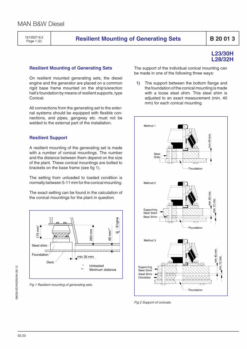
0802
8-0D
/H52
50/9
4.08
.12
MAN B&W Diesel
The support of the individual conical mounting canbe made in one of the following three ways:
1) The support between the bottom flange andthe foundation of the conical mounting is madewith a loose steel shim. This steel shim isadjusted to an exact measurement (min. 40mm) for each conical mounting.
Resilient Mounting of Generating Sets
On resilient mounted generating sets, the dieselengine and the generator are placed on a commonrigid base frame mounted on the ship's/erectionhall's foundation by means of resilient supports, typeConical.
All connections from the generating set to the exter-nal systems should be equipped with flexible con-nections, and pipes, gangway etc. must not bewelded to the external part of the installation.
Resilient Support
A resilient mounting of the generating set is madewith a number of conical mountings. The numberand the distance between them depend on the sizeof the plant. These conical mountings are bolted tobrackets on the base frame (see fig 1).
The setting from unloaded to loaded condition isnormally between 5-11 mm for the conical mounting.
The exact setting can be found in the calculation ofthe conical mountings for the plant in question.
Resilient Mounting of Generating Sets
02.23
Fig 2 Support of conicals.
L23/30HL28/32H
Fig 1 Resilient mounting of generating sets.
B 20 01 31613527-9.2Page 1 (2)
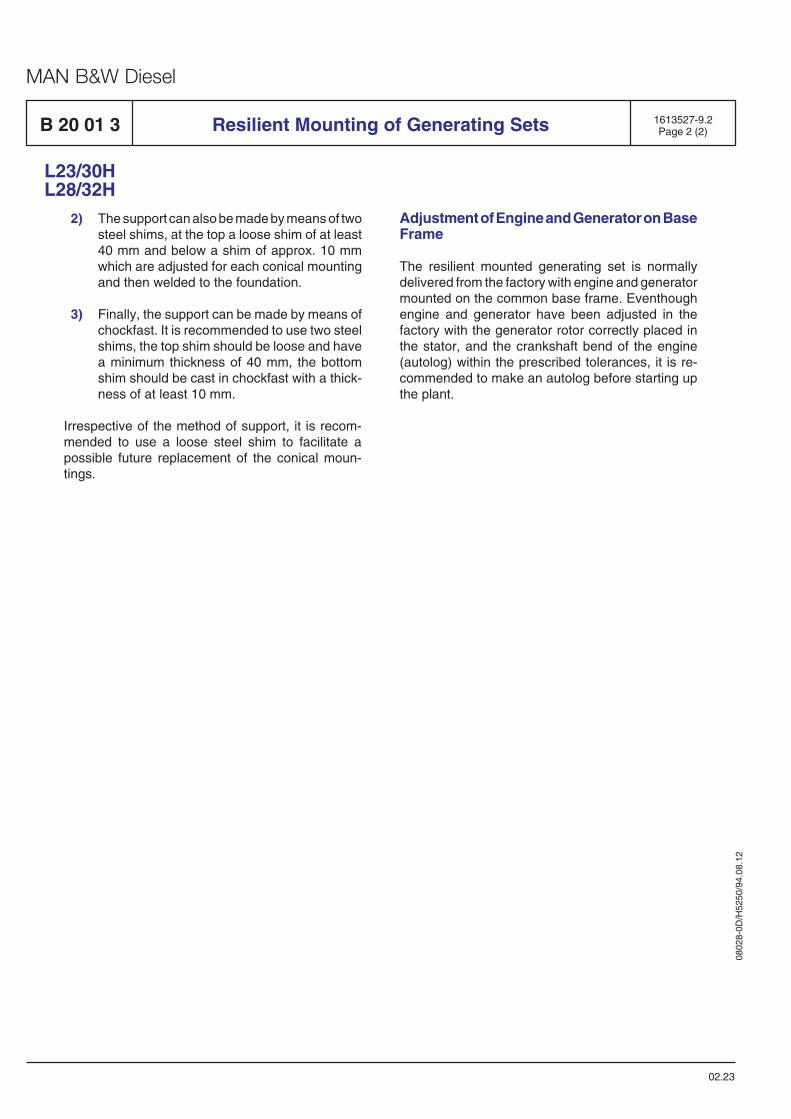
0802
8-0D
/H52
50/9
4.08
.12
MAN B&W Diesel
Resilient Mounting of Generating Sets 1613527-9.2Page 2 (2)
02.23
Adjustment of Engine and Generator on BaseFrame
The resilient mounted generating set is normallydelivered from the factory with engine and generatormounted on the common base frame. Eventhoughengine and generator have been adjusted in thefactory with the generator rotor correctly placed inthe stator, and the crankshaft bend of the engine(autolog) within the prescribed tolerances, it is re-commended to make an autolog before starting upthe plant.
L23/30HL28/32H
2) The support can also be made by means of twosteel shims, at the top a loose shim of at least40 mm and below a shim of approx. 10 mmwhich are adjusted for each conical mountingand then welded to the foundation.
3) Finally, the support can be made by means ofchockfast. It is recommended to use two steelshims, the top shim should be loose and havea minimum thickness of 40 mm, the bottomshim should be cast in chockfast with a thick-ness of at least 10 mm.
Irrespective of the method of support, it is recom-mended to use a loose steel shim to facilitate apossible future replacement of the conical moun-tings.
B 20 01 3

Test running
B 21

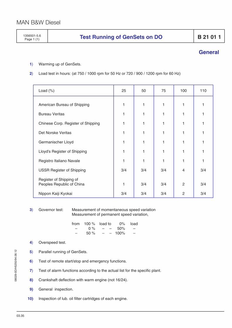
0802
8-0D
/H52
50/9
4.08
.12
MAN B&W Diesel
Test Running of GenSets on DO1356501-5.6Page 1 (1) B 21 01 1
General
1) Warming up of GenSets.
2) Load test in hours: (at 750 / 1000 rpm for 50 Hz or 720 / 900 / 1200 rpm for 60 Hz)
Load (%)
American Bureau of Shipping
Bureau Veritas
Chinese Corp. Register of Shipping
Det Norske Veritas
Germanischer Lloyd
Lloyd's Register of Shipping
Registro Italiano Navale
USSR Register of Shipping
Register of Shipping ofPeoples Republic of China
Nippon Kaiji Kyokai
25
1
1
1
1
1
1
1
3/4
1
3/4
50
1
1
1
1
1
1
1
3/4
3/4
3/4
75
1
1
1
1
1
1
1
3/4
3/4
3/4
100
1
1
1
1
1
1
1
4
2
2
110
1
1
1
1
1
1
1
3/4
3/4
3/4
03.35
3) Governor test: Measurement of momentaneous speed variationMeasurement of permanent speed variation,
from 100 % load to 0% load– 0 % – – 50% –– 50 % – – 100% –
4) Overspeed test.
5) Parallel running of GenSets.
6) Test of remote start/stop and emergency functions.
7) Test of alarm functions according to the actual list for the specific plant.
8) Crankshaft deflection with warm engine (not 16/24).
9) General inspection.
10) Inspection of lub. oil filter cartridges of each engine.


Spare Parts
E 23


0802
8-0D
/H52
50/9
4.08
.12
MAN B&W Diesel
1613435-6.1Page 1 (1) Weight and Dimensions of Principal Parts E 23 00 0
L23/30H
91.37
Cylinder liner approx. 75 kg
Connecting rod approx. 41 kg
Piston approx. 21 kg
Cylinder head approx.130 kgCylinder head incl. rocker arms approx. 180 kg

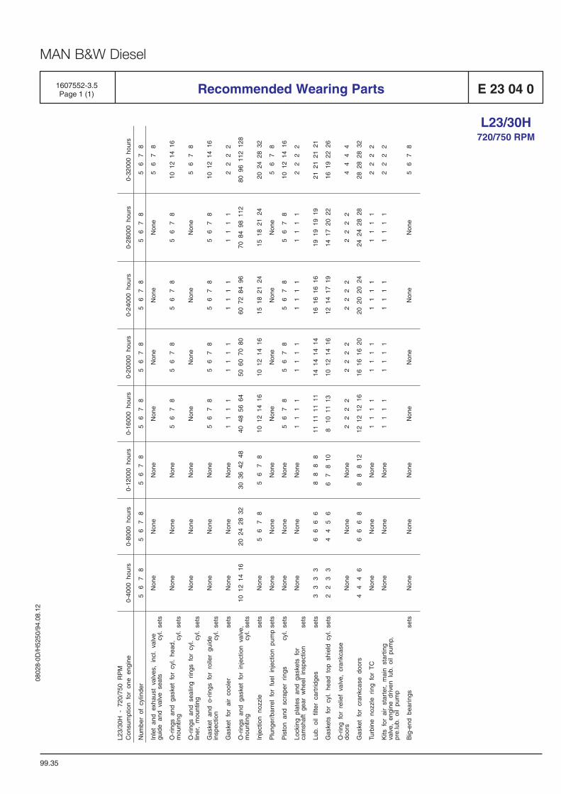
0802
8-0D
/H52
50/9
4.08
.12
MAN B&W Diesel
1607552-3.5Page 1 (1) Recommended Wearing Parts E 23 04 0
99.35
L23/30H720/750 RPM

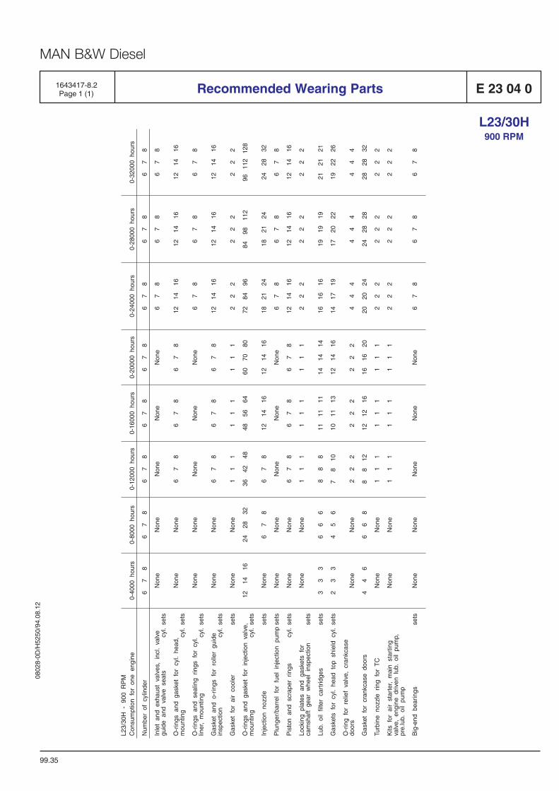
0802
8-0D
/H52
50/9
4.08
.12
MAN B&W Diesel
1643417-8.2Page 1 (1) Recommended Wearing Parts E 23 04 0
99.35
L23/30H900 RPM

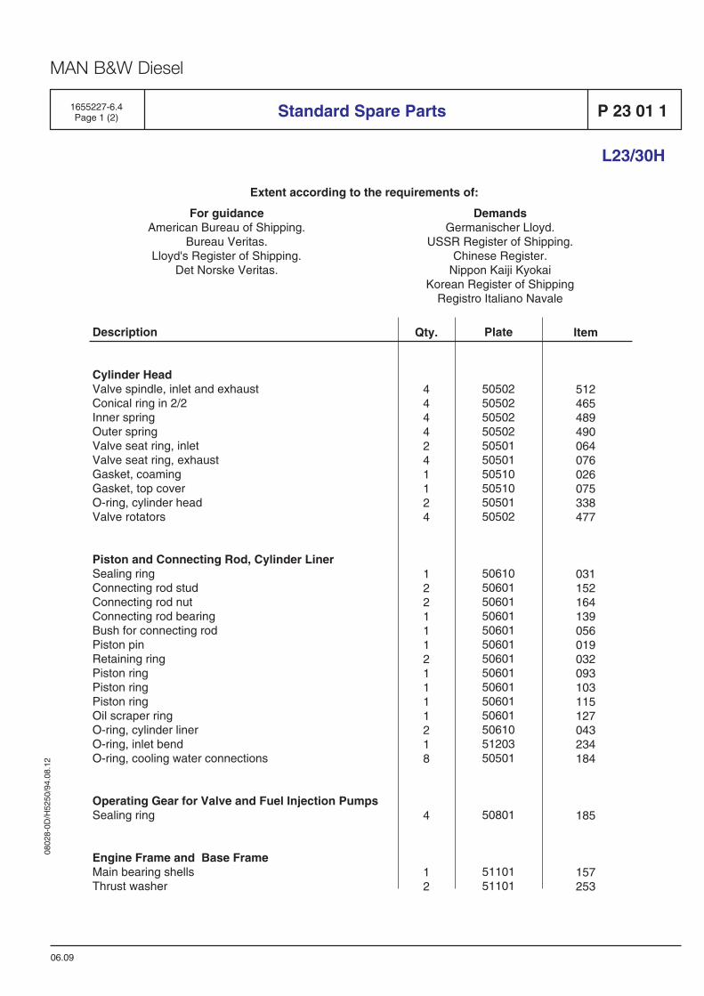
0802
8-0D
/H52
50/9
4.08
.12
MAN B&W Diesel
For guidanceAmerican Bureau of Shipping.
Bureau Veritas.Lloyd's Register of Shipping.
Det Norske Veritas.
DemandsGermanischer Lloyd.
USSR Register of Shipping.Chinese Register.
Nippon Kaiji KyokaiKorean Register of Shipping
Registro Italiano Navale
Extent according to the requirements of:
L23/30H
1655227-6.4Page 1 (2)
06.09
Standard Spare Parts P 23 01 1
Plate
50502505025050250502505015050150510505105050150502
5061050601506015060150601506015060150601506015060150601506105120350501
50801
5110151101
Description
Cylinder HeadValve spindle, inlet and exhaustConical ring in 2/2Inner springOuter springValve seat ring, inletValve seat ring, exhaustGasket, coamingGasket, top coverO-ring, cylinder headValve rotators
Piston and Connecting Rod, Cylinder LinerSealing ringConnecting rod studConnecting rod nutConnecting rod bearingBush for connecting rodPiston pinRetaining ringPiston ringPiston ringPiston ringOil scraper ringO-ring, cylinder linerO-ring, inlet bendO-ring, cooling water connections
Operating Gear for Valve and Fuel Injection PumpsSealing ring
Engine Frame and Base FrameMain bearing shellsThrust washer
Qty.
4444241124
12211121111218
4
12
Item
512465489490064076026075338477
031152164139056019032093103115127043234184
185
157253
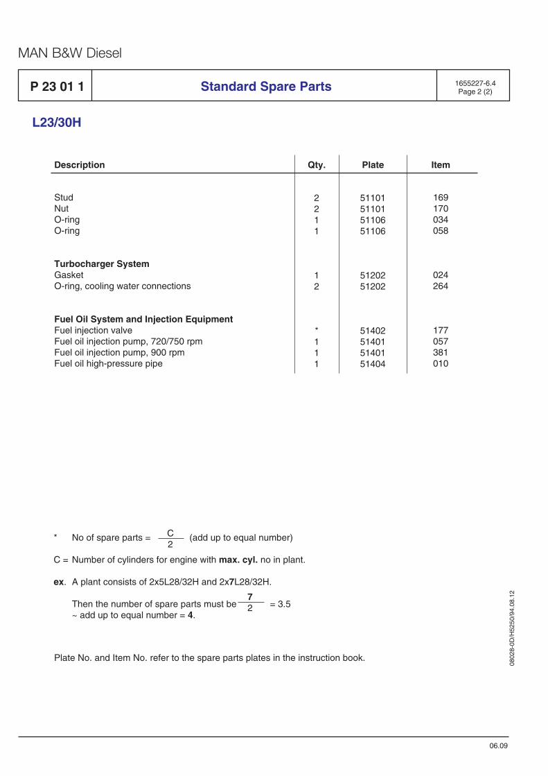
0802
8-0D
/H52
50/9
4.08
.12
MAN B&W Diesel
51101511015110651106
5120251202
51402514015140151404
L23/30H
Description Qty. Plate Item
P 23 01 1 Standard Spare Parts 1655227-6.4Page 2 (2)
06.09
StudNutO-ringO-ring
Turbocharger SystemGasketO-ring, cooling water connections
Fuel Oil System and Injection EquipmentFuel injection valveFuel oil injection pump, 720/750 rpmFuel oil injection pump, 900 rpmFuel oil high-pressure pipe
2211
12
*111
169170034058
024264
177057381010
Plate No. and Item No. refer to the spare parts plates in the instruction book.
* No of spare parts = (add up to equal number)
C = Number of cylinders for engine with max. cyl. no in plant.
ex. A plant consists of 2x5L28/32H and 2x7L28/32H.
Then the number of spare parts must be = 3.5~ add up to equal number = 4.
C2
72

Tools
P 24

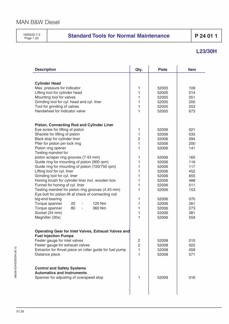
0802
8-0D
/H52
50/9
4.08
.12
MAN B&W Diesel
Plate
520055200552005520055200552005
5200652006520065200652006
5200652006520065200652006520065200652006
5200652006520065200652006
52008520085200852008
52009
Standard Tools for Normal Maintenance
L23/30H
Qty.
111111
11211
11111111
11111
2211
1
Item
109014051205553673
021033094200141
165116117452655488511153
070261273381559
010022058071
016
P 24 01 11655222-7.3Page 1 (2)
01.25
Description
Cylinder HeadMax. pressure for indicatorLifting tool for cylinder headMounting tool for valvesGrinding tool for cyl. head and cyl. linerTool for grinding of valvesHandwheel for indicator valve
Piston, Connecting Rod and Cylinder LinerEye screw for lifting of pistonShackle for lifting of pistonBack stop for cylinder linerPlier for piston pin lock ringPiston ring openerTesting mandrel forpiston scraper ring grooves (7.43 mm)Guide ring for mounting of piston (900 rpm)Guide ring for mounting of piston (720/750 rpm)Lifting tool for cyl. linerGrinding tool for cyl. linerHoning brush for cylinder liner incl. wooden boxFunnel for honing of cyl. linerTesting mandrel for piston ring grooves (4.43 mm)Eye bolt for piston lift af check of connecting rodbig-end bearingTorque spanner 20 - 120 NmTorque spanner 80 - 360 NmSocket (24 mm)Magnifier (30x)
Operating Gear for Inlet Valves, Exhaust Valves andFuel Injection PumpsFeeler gauge for inlet valvesFeeler gauge for exhaust valvesExtractor for thrust piece on roller guide for fuel pumpDistance piece
Control and Safety SystemsAutomatics and InstrumentsSpanner for adjusting of overspeed stop
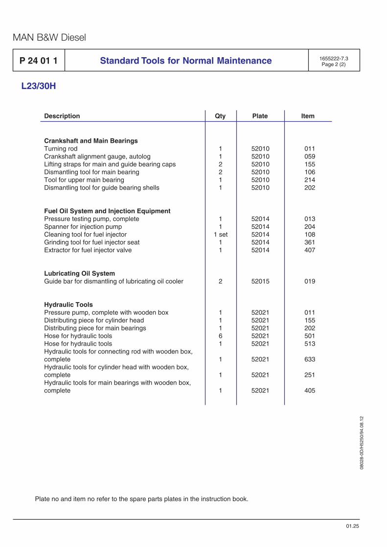
0802
8-0D
/H52
50/9
4.08
.12
MAN B&W Diesel
L23/30H
01.25
P 24 01 1 Standard Tools for Normal Maintenance 1655222-7.3Page 2 (2)
Plate no and item no refer to the spare parts plates in the instruction book.
Description Qty Plate Item
Crankshaft and Main BearingsTurning rodCrankshaft alignment gauge, autologLifting straps for main and guide bearing capsDismantling tool for main bearingTool for upper main bearingDismantling tool for guide bearing shells
Fuel Oil System and Injection EquipmentPressure testing pump, completeSpanner for injection pumpCleaning tool for fuel injectorGrinding tool for fuel injector seatExtractor for fuel injector valve
Lubricating Oil SystemGuide bar for dismantling of lubricating oil cooler
Hydraulic ToolsPressure pump, complete with wooden boxDistributing piece for cylinder headDistributing piece for main bearingsHose for hydraulic toolsHose for hydraulic toolsHydraulic tools for connecting rod with wooden box,completeHydraulic tools for cylinder head with wooden box,completeHydraulic tools for main bearings with wooden box,complete
112211
11
1 set11
2
11161
1
1
1
520105201052010520105201052010
5201452014520145201452014
52015
5202152021520215202152021
52021
52021
52021
011059155106214202
013204108361407
019
011155202501513
633
251
405
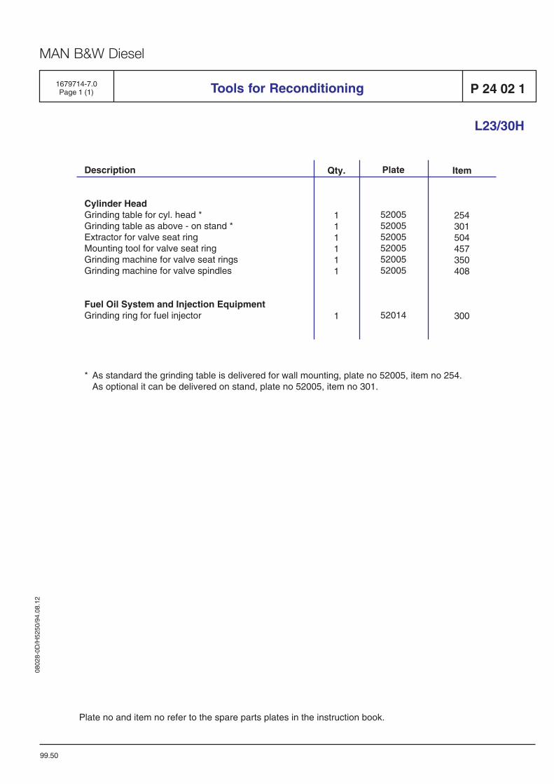
0802
8-0D
/H52
50/9
4.08
.12
MAN B&W Diesel
Description
Cylinder HeadGrinding table for cyl. head *Grinding table as above - on stand *Extractor for valve seat ringMounting tool for valve seat ringGrinding machine for valve seat ringsGrinding machine for valve spindles
Fuel Oil System and Injection EquipmentGrinding ring for fuel injector
1679714-7.0Page 1 (1) Tools for Reconditioning
99.50
Qty.
111111
1
Plate
520055200552005520055200552005
52014
Item
254301504457350408
300
L23/30H
P 24 02 1
Plate no and item no refer to the spare parts plates in the instruction book.
* As standard the grinding table is delivered for wall mounting, plate no 52005, item no 254.As optional it can be delivered on stand, plate no 52005, item no 301.

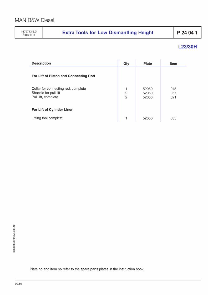
0802
8-0D
/H52
50/9
4.08
.12
MAN B&W Diesel
Description
For Lift of Piston and Connecting Rod
Collar for connecting rod, completeShackle for pull liftPull lift, complete
For Lift of Cylinder Liner
Lifting tool complete
Extra Tools for Low Dismantling Height1679713-5.0Page 1(1) P 24 04 1
L23/30H
Qty
122
1
Plate
520505205052050
52050
Item
045057021
033
99.50
Plate no and item no refer to the spare parts plates in the instruction book.


G 50 Alternator
B 50

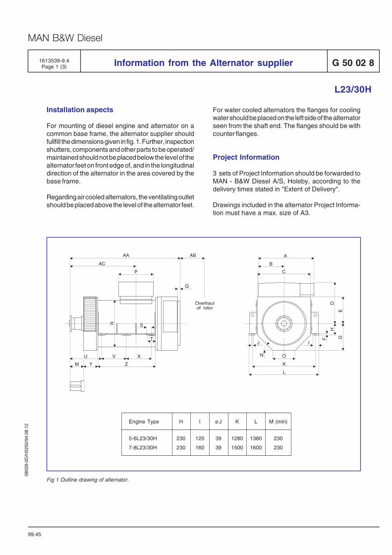
0802
8-0D
/H52
50/9
4.08
.12
MAN B&W Diesel
For water cooled alternators the flanges for coolingwater should be placed on the left side of the alternatorseen from the shaft end. The flanges should be withcounter flanges.
Project Information
3 sets of Project Information should be forwarded toMAN - B&W Diesel A/S, Holeby, according to thedelivery times stated in "Extent of Delivery".
Drawings included in the alternator Project Informa-tion must have a max. size of A3.
Installation aspects
For mounting of diesel engine and alternator on acommon base frame, the alternator supplier shouldfullfill the dimensions given in fig. 1. Further, inspectionshutters, components and other parts to be operated/maintained should not be placed below the level of thealternator feet on front edge of, and in the longitudinaldirection of the alternator in the area covered by thebase frame.
Regarding air cooled alternators, the ventilating outletshould be placed above the level of the alternator feet.
G 50 02 8Information from the Alternator supplier
L23/30H
1613539-9.4Page 1 (3)
99.45
A
B
C
D
E
F
N
GIJ
O
K
L
H
AA
P
R
T
X
Z
VU
M Y
AC
AB
Q
Overhaulof rotor
S
Engine Type H I øJ K L M (min)
5-6L23/30H 230 120 39 1280 1380 230
7-8L23/30H 230 160 39 1500 1600 230
Fig 1 Outline drawing of alternator.
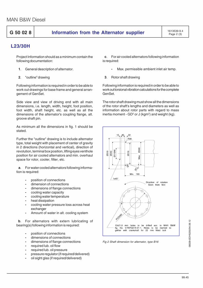
0802
8-0D
/H52
50/9
4.08
.12
MAN B&W Diesel
Project Information should as a minimum contain thefollowing documentation:
1. General description of alternator.
2. "outline" drawing
Following information is required in order to be able towork out drawings for base frame and general arran-gement of GenSet.
Side view and view of driving end with all maindimensions, i.e. length, width, height, foot position,foot width, shaft height, etc. as well as all thedimensions of the alternator's coupling flange, alt.groove shaft pin.
As minimum all the dimensions in fig. 1 should bestated.
Further the "outline" drawing is to include alternatortype, total weight with placement of center of gravityin 2 directions (horizontal and vertical), direction ofrevolution, terminal box position, lifting eyes ventholeposition for air cooled alternators and min. overhaulspace for rotor, cooler, filter, etc.
a. For water cooled alternators following informa-tion is required:
- position of connections- dimension of connections- dimensions of flange connections- cooling water capacity- cooling water temperature- heat dissipation- cooling water pressure loss across heat
exchanger- Amount of water in alt. cooling system
b. For alternators with extern lubricating ofbearing(s) following information is required:
- position of connections- dimensions of connections- dimensions of flange connections- required lub. oil flow- required lub. oil pressure- pressure regulator (if required/delivered)- oil sight glas (if required/delivered)
c. For air cooled alternators following informationis required:
- Max. permissible ambient inlet air temp.
3. Rotor shaft drawing
Following information is required in order to be able towork out torsional vibration calculations for the completeGenSet.
The rotor shaft drawing must show all the dimensionsof the rotor shaft's lengths and diameters as well asinformation about rotor parts with regard to massinertia moment - GD2 or J (kgm2) and weight (kg).
Information from the Alternator supplierG 50 02 8
L23/30H
99.45
1613539-9.4Page 2 (3)
Fig 2 Shaft dimension for alternator, type B16
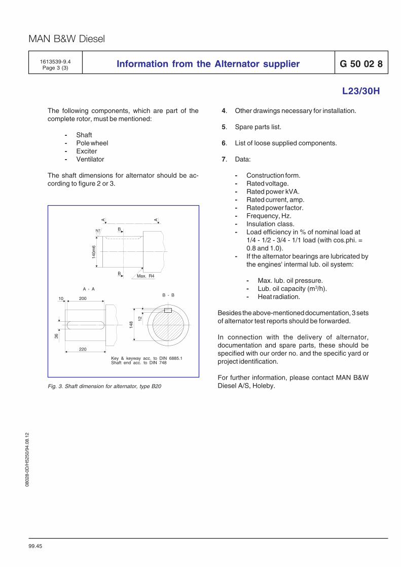
0802
8-0D
/H52
50/9
4.08
.12
MAN B&W Diesel
G 50 02 8Information from the Alternator supplier
L23/30H
1613539-9.4Page 3 (3)
99.45
The following components, which are part of thecomplete rotor, must be mentioned:
- Shaft- Pole wheel- Exciter- Ventilator
The shaft dimensions for alternator should be ac-cording to figure 2 or 3.
4. Other drawings necessary for installation.
5. Spare parts list.
6. List of loose supplied components.
7. Data:
- Construction form.- Rated voltage.- Rated power kVA.- Rated current, amp.- Rated power factor.- Frequency, Hz.- Insulation class.- Load efficiency in % of nominal load at
1/4 - 1/2 - 3/4 - 1/1 load (with cos.phi. =0.8 and 1.0).
- If the alternator bearings are lubricated bythe engines' intermal lub. oil system:
- Max. lub. oil pressure.- Lub. oil capacity (m3/h).- Heat radiation.
Besides the above-mentioned documentation, 3 setsof alternator test reports should be forwarded.
In connection with the delivery of alternator,documentation and spare parts, these should bespecified with our order no. and the specific yard orproject identification.
For further information, please contact MAN B&WDiesel A/S, Holeby.Fig. 3. Shaft dimension for alternator, type B20
220
20010
36
A - A
12
148
B - B
140m
6
Max. R4
B
AA
B
N7
Key & keyway acc. to DIN 6885.1Shaft end acc. to DIN 748

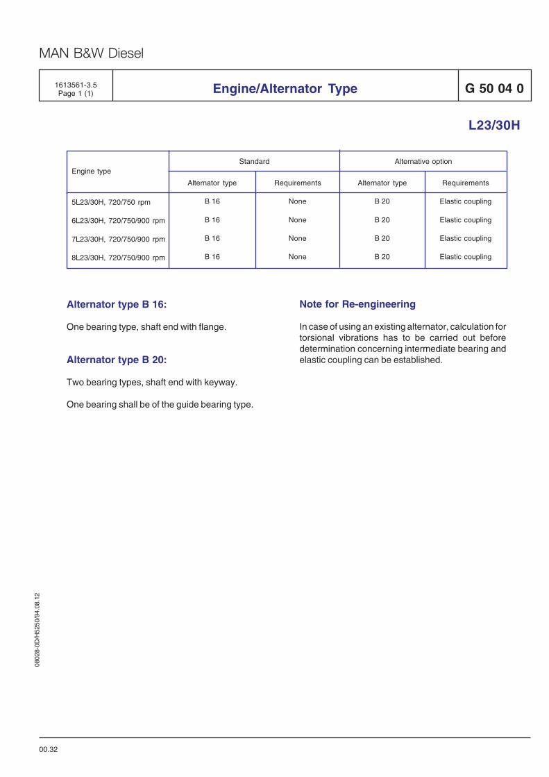
0802
8-0D
/H52
50/9
4.08
.12
MAN B&W Diesel
1613561-3.5Page 1 (1) Engine/Alternator Type
00.32
L23/30H
G 50 04 0
5L23/30H, 720/750 rpm
6L23/30H, 720/750/900 rpm
7L23/30H, 720/750/900 rpm
8L23/30H, 720/750/900 rpm
Engine typeStandard Alternative option
Requirements
Elastic coupling
Elastic coupling
Elastic coupling
Elastic coupling
Alternator type
B 20
B 20
B 20
B 20
Requirements
None
None
None
None
Alternator type
B 16
B 16
B 16
B 16
Alternator type B 16:
One bearing type, shaft end with flange.
Alternator type B 20:
Two bearing types, shaft end with keyway.
One bearing shall be of the guide bearing type.
Note for Re-engineering
In case of using an existing alternator, calculation fortorsional vibrations has to be carried out beforedetermination concerning intermediate bearing andelastic coupling can be established.


B 25 Preservation and Packing
B 98

0802
8-0D
/H52
50/9
4.08
.12
MAN B&W Diesel
1350467-1.3Page 1 (1) Preservation of diesel engine before dispatch B 25 01 1
01.10
General
Preservation of Diesel Engine:
1) Lubricating oil system.
Lub. oil is drained from base frame, lub. oil filter andcooler.
After cleaning of the engine and the base frame, arust-preventing lubricating oil is added, and theentire lub. oil system is primed.
The oil is just covering the bottom of the base frame.
The following types of oils are suitable:
Mobilarma 524.
Esso Rustban 335.
Chevron EP Industrial Oil 68.
Shells Ensis Oil SAE 30 / SAE 10 W.
BP Protective Oil 30/40.
2) Fuel oil system.
The fuel oil is drained. The fuel valves are cleanedand pressure tested with Mobil White-Terex 309 orsimilar, and the entire fuel oil system is filled with thistype of oil.
3) Bright components internal or external on thediesel engine such as crankshaft, camshaft and gearwheels are covered with Mobilux EP004.
4) Bags with a hygroscopic product are sus-pended inside the diesel engine in the crankcase.The bags are equipped with a humidity indicator.
SilicaGel or a similar product can be used in aquantity of 3000 grams/m3.
The bags must not touch any surfaces, and if ne-cessary the surface is covered with a plastic sheet.
5) All external surfaces are sprayed with a protec-tive layer of Valvoline tectyl 511M.
6) All openings and flange connections are care-fully closed.
7) Electric boxes are protected inside by volatilecorrosion inhibitor tape.

0802
8-0D
/H52
50/9
4.08
.12
MAN B&W Diesel
B 25 01 1Preservation of Spare Parts and Tools
01.13
1350473-0.4Page 1 (1)
General
Spare parts and tools.
Preservation of supplied spare parts and tools aremade as follows:
Dinitrol 25B or Dinitrol 3850
special tools in boxes are protected by a volatilecorrosion inhibitor tape
Storage conditions
The boxes must always be stored under roof, pro-tected from direct rain, sea-fog and dust. The boxesmust be covered with tarpaulin.
Maintenance of preservation
Immediately upon arrival the boxes are to be openedand the parts examined for damage to the preser-vation, and if necessary repaired.
This procedure must be repeated every 2-4 monthsdepending on the storage conditions.
Smaller boxes containing special tools such as:
grinding machine for valve seats
indicator
test equipment for fuel valves
measuring equipment
etc.
must be removed from the shipment, inspected forcorrosion and stored in a dry place.
After inspection the boxes with the spare parts mustbe closed and covered with tarpaulin.
Cleaning of parts can be made with petroleum,turpentine or similar solvents.
Notice:Special preservation can be made on re-quest.

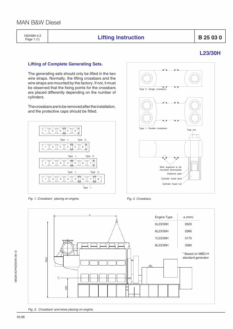
0802
8-0D
/H52
50/9
4.08
.12
MAN B&W Diesel
1624484-4.2Page 1 (1)
03.08
Lifting of Complete Generating Sets.
The generating sets should only be lifted in the twowire straps. Normally, the lifting crossbars and thewire straps are mounted by the factory. If not, it mustbe observed that the fixing points for the crossbarsare placed differently depending on the number ofcylinders.
The crossbars are to be removed after the installation,and the protective caps should be fitted.
Lifting Instruction B 25 03 0
L23/30H
Fig. 3. Crossbars' and wires placing on engine.
Fig. 1. Crossbars' placing on engine. Fig. 2. Crossbars.
Wire supports to bemounted downwards
Cap nut
Distance pipe
Cylinder head nut
Cylinder head stud
Type 1. Double crossbars.
Type 2. Single crossbars.
Engine Type a (mm)
5L23/30H 2620
6L23/30H 2990
7L23/30H 3175
8L23/30H 3360
* Based on MBD-Hstandard generator