pentair.com Item
# E
-03-
491
| Pa
rt #
562
5-49
1-1
| (
05/1
7/19
) © 2
019
Pent
air
INSTALLATION AND OPERATION MANUAL
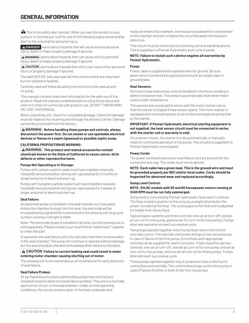
SUBMERSIBLE SOLIDS HANDLING PUMPS S4L(Xˆ) S4LRC/S4LVXˆ S4B(Xˆ) S4K(Xˆ), H4Q(Xˆ) S6L(Xˆ) S6A(Xˆ) S8F(Xˆ)ˆUsed In Hazardous Locations Class I, Division 1
HYDROMATIC*

2 E-03-491 (06-10-19)
TABLE OF CONTENTS:
SECTION .................................................................................................................................................................................................. PAGE
General Information .................................................................................................................................................................................. 3
Pump Installation ...................................................................................................................................................................................... 4
Pump Operations ...................................................................................................................................................................................... 5
Pump Maintenance ................................................................................................................................................................................... 6
Pump Troubleshooting ............................................................................................................................................................................. 7
Wet End Components ............................................................................................................................................................................... 8
Wet End Parts List .................................................................................................................................................................................... 9
Motor End Components, Standard Location (S4L, S4LRC, S4B, S4K, H4Q, S6L, S6A and S8F) ................................................................10
Motor End Parts List, Standard Location (S4L, S4LRC, S4B, S4K, H4Q, S6L, S6A and S8F) .................................................................... 11
Motor End Components, Hazardous Location (S4LX, S4LVX, S4BX, S4KX, H4QX, S6LX, S6AX and S8FX) ..............................................12
Motor End Parts List, Hazardous Location (S4LX, S4LVX, S4BX, S4KX, H4QX, S6LX, S6AX and S8FX) ............................................. 13-14
Wiring Diagrams ......................................................................................................................................................................................15
Standard Limited Warranty .....................................................................................................................................................................16
3 E-03-491 (06-10-19)
GENERAL INFORMATION
This is the safety alert symbol. When you see this symbol on your pump or in this manual, look for one of the following signal words and be alert to the potential for personal injury.
warns about hazards that will cause serious personal injury, death or major property damage if ignored.
warns about hazards that can cause serious personal injury, death or major property damage if ignored.
warns about hazards that will or can cause minor personal injury or property damage if ignored.
The label NOTICE indicates special instructions which are important but not related to hazards.
Carefully read and follow all safety instructions in this manual and on pump.
This manual contains important information for the safe use of this product. Read this manual completely before using this product and refer to it often for continued safe product use. DO NOT THROW AWAY OR LOSE THIS MANUAL.
When unpacking unit, check for concealed damage. Claims for damage must be made at the receiving end through the delivery carrier. Damage cannot be processed from the factory.
Before handling these pumps and controls, always disconnect the power first. Do not smoke or use sparkable electrical devices or flames in a septic (gaseous) or possible septic sump.
CALIFORNIA PROPOSITION 65 WARNING: This product and related accessories contain
chemicals known to the State of California to cause cancer, birth defects or other reproductive harm.
Pumps Not Operating or in Storage:Pumps with carbon ceramic seals must have impellers manually rotated (6 revolutions) after sitting non-operational for 3 months or longer and prior to electrical start-up.
Pumps with tungsten carbide seals must have impellers manually rotated (6 revolutions) after sitting non-operational for 3 weeks or longer and prior to electrical start-up.
Seal Failure:An electrode probe is installed in the seal chamber so if any water enters the chamber through the first seal, the electrode will be energized and a signal will be transmitted to the sensing unit at ground surface causing a red light to flash.
Note: The electrode probe is installed in all units, but the sensing unit is sold separately. Please contact your local Pentair Hydromatic* supplier to order this part.
In operation the seal failure unit only indicates that there is some water in the seal chamber. The pump will continue to operate without damage, but the seal should be checked immediately after failure is indicated.
Failure to correct leaking seal could result in water entering motor chamber causing shorting out of motor.The sensing unit is recommended on all installations for early detection of seal failure.
Seal Failure Probes:All our hazardous location submersible pumps have two factory installed moisture detectors (seal failure probes). They are in a normally open series circuit, in the seal chamber. Under normal operating conditions, the circuit remains open. If the lower seal leaks and
moisture enters this chamber, the moisture would settle to the bottom of the chamber and will complete the circuit between the moisture detectors.
This circuit must be connected to a sensing unit and signaling device. This is supplied in a Pentair Hydromatic built control panel.
NOTE: Failure to install such a device negates all warranties by Pentair Hydromatic.
Pump:Power cable is supplied with separate wire for ground. Be sure green wire is connected to a good ground such as a water pipe or ground stake.
Heat Sensors:All motors have heat sensor units embedded in the motor winding to detect excessive heat. The sensors automatically reset when motor cools to safe temperature.
The sensors are connected in series with the motor starter coil so that the starter is tripped if heat sensor opens. The motor starter is equipped with overload heaters so all normal overloads are protected by the starter.
IMPORTANT: If Pentair Hydromatic electrical starting equipment is not supplied, the heat sensor circuit must be connected in series with the starter coil or warranty is void.Once sensor resets, the starter is to be automatically or manually reset for continued operation of the pump. This circuitry is supplied in a Pentair Hydromatic control panel.
Power Cords:The power cord and heat sensor seal failure cord are potted into the connection box cap. The cords must not be spliced.
NOTE: Each cable has a green lead. This is the ground wire and must be grounded properly per NEC and/or local codes. Cords should be inspected for abnormal wear and replaced accordingly.
Sump Level Control:NOTE: S4LRC models with 50 and 60 horsepower motors running at 3450 RPM must be run fully submerged. Sump level is controlled by Pentair Hydromatic float switch controls. The float is held in position in the sump by a weight attached to the power cord above the float. The cord supports the float and is adjusted for height from the surface.
Typical duplex systems use three controls: one set at turn-off, one set at turn-on for one pump, and one set for turn-on for two pumps. Pumps alternate operation on each successive cycle.
Two pumps operate together only if sump level rises to the third or override control. The override control also brings on the second pump in case of failure of the first pump. Extra floats with appropriate controls can be supplied for alarm functions. Triplex systems use four controls: one set at turn-off, one set at turn-on for one pump, one set at turn-on for two pumps, and one set at turn-on for three pumps. Pumps alternate each successive cycle.
Three pumps operate together only if sump level rises to the fourth control (second override). This control also brings on the third pump in case of failure of either or both of the first two pumps.

4 E-03-491 (06-10-19)
PUMP INSTALLATION
Alarm Controls:The alarm level is usually set above the override level so the alarm will signal only if the override level is exceeded. However, some engineers prefer to have the alarm level set below the override level as it is possible for one pump to fail and the other pump to operate on the override level with the sump level never reaching the alarm level. This is particularly true in cases of low inflow capacity.
Electrical Control Panel:It is recommended that the Pentair Hydromatic* control panel be used with all pumps as proper starter heaters and connections for heat sensor wires are included.
The electrical equipment includes a main circuit breaker, a magnetic starter with overload protection, an H-O-A switch and run light for each pump, an electric alternator and a transformer to provide appropriate control circuit and alarms.
Overload Heaters:If the Pentair Hydromatic electrical panel is not used, starters with 3 leg overload protection must be supplied. The heaters must be sized in accordance with the nameplate amps on the motor housing. The amp draw on these submersible motors is slightly higher than a corresponding horsepower surface motor, so heaters must be sized by the nameplate rating.
IMPORTANT: Be sure the heat sensor wires are connected in series with the starter coil circuit.
PUMP INSTALLATION Installing Pump in Sump:Before installing pump in sump, lay it on its side and turn impeller manually. Impeller may be slightly stuck due to factory test water, so it must be broken loose with a small bar or screwdriver in edge of vanes. The impeller should turn freely.
Clean all trash and sticks from sump and connect pump to piping.
A check valve must be installed on each pump. A gate or plug valve in each pump discharge line is also recommended. This valve should be installed on the discharge side of the check valve so if necessary to service the check valve, the line pressure can be cut off. Single pump systems are sometimes installed without a check valve where it is desirable to self-drain the discharge line to prevent freezing. This can be done only with short discharge lines, otherwise water will return to the sump and cause short cycling of the pump.
Installing Sump Level Control Float Controls:In either simplex, duplex or triplex systems the lower or turn-off control is to be set to maintain a minimum level in the sump. This level shall be no more than 3-1/4" from the top of the motor housing down to the surface of the sewage.
The second or turn-on control is set above the lower turn-off control. The exact distance between the two floats must be a compromise between a frequent pumping cycle (10 starts per hour max.) to control septicity, solids and a slower cycle for energy economy. This distance should be determined by the engineer or consulting engineer depending on the conditions of the application.
For installation of Pentair Hydromatic supplied level controls, refer to your systems installation and service manual.
NEMA 4 Junction Box (Optional):If an electrical control panel is to be set remote from the sump pump a NEMA 4 junction box should be used to make power and control connections. The Pentair Hydromatic NEMA 4 junction box is provided with compression connectors for sealing all wires. No sealing compound is needed to make connections waterproof.
Wiring diagrams are provided with panel for making connections. The size wire to use from panel to sump depends on motor size and distance in feet.
Be sure each wire is checked out so that a wrong connection will not be made. An ohmmeter or Megger® can be used to check wire continuity.
Installing Float Switch Controls:The controls are supported by a mounting bracket that is attached to the sump wall, cover or NEMA 4 junction box.
Cord snubbers are used to hold the cord in place. Control lever can be changed at any time by loosening the snubber and readjusting cord length.
In either simplex or duplex system the lower or turn-off control is set just above the top of volute so that the volute will always be submerged during the pumping cycle. The second or turn-on control is set about 24 inches above the lower turn-off control.
Distance between turn-on and turn-off controls may be increased, but may result in sewage becoming septic or a higher amount of solids than the pump can handle. A frequent pumping cycle is recommended for best operation.
If an alarm system is used, this control is usually set about 6 inches above the override control.
NUMBER OF CONDUCTORS REQUIRED BETWEEN CONTROL PANEL AND NEMA 4 JUNCTION BOX Power lines and control wires can be carried in conduit or can be underground buried cable.
SystemType
Number ofControl Wires
Number ofPower Lines
Number ofGround Wires #8
HEAT SENSOR & SEAL FAILURE
Number of Sensor Wires Number of Ground Wires
Simplex 3 3 1 3 1
Simplex with Alarm 5 3 1 3 1
Duplex 5 6 1 6 2
Duplex with Alarm 7 6 1 6 2

5 E-03-491 (06-10-19)
PUMP OPERATIONS
Making Electrical Connections:All electrical wiring must be in accordance with the local code, and only electricians should make the installations. Complete wiring diagrams are on the inside cover of the panel. All wires should be checked for ground with an ohmmeter or Megger® after the connections are made. This is important, as one grounded wire can impact operation effectiveness.
IMPORTANT: If equipment is not properly wired and protected as recommended, the warranty is void.
Heat Sensors and Seal Failure Connections:Be sure that heat sensor wires are connected in series with the starter coil. Connections are provided on the terminal strip.
PUMP OPERATIONS Starting System: 1. Turn H-O-A switch to Off position, then turn on main circuit
breakers.
2. Open all discharge valves and allow water to rise in sump pump.
3. Turn H-O-A switch to Hand position on one pump and notice operation. If pump is noisy and vibrates, rotation is wrong. To change rotation interchange any two line leads to motor on 3ø only. DO NOT INTERCHANGE MAIN INCOMING LINES. If duplex or triplex system, check additional pumps in the same manner.
4. Now set both H-O-A switches to Auto position and allow water to rise in sump until one pump starts. Allow pump to operate until the level drops to turn-off point.
5. Allow sump level to rise to start other pump. Notice run lights on panel; pumps should alternate on each successive cycle of operation.
6. Turn both H-O-A switches to Off position and allow sump to fill to the override control level.
7. Turn both switches to Auto position and both pumps should start and operate together until level drops to turn-off point.
8. Repeat this operation cycle several times before leaving the job.
9. Check voltage when pumps are operating and check the amp draw of each pump. Check amps on each wire as sometimes a high leg will exist. One leg can be somewhat higher, 5 to 10%, without causing trouble. For excessive amp draw on one leg, the power company should be consulted.
Phase Converters:Phase converters are generally not recommended, but in cases where only single phase current is available phase converter can be used. Be sure to size the phase converter large enough for the amp draw specified on the motor nameplate, not necessarily by motor horsepower. The warranty on all three phase submersible motors is void if operated with single phase power through a phase converter and 3 leg ambient compensated extra-quick trip overload protectors are not used.
DUAL VOLTAGE3 PHASE MOTOR WIRING
230V 3N 460V 3N
GREEN GREENR
(L3)W
(L2)BL
(L1)R
(L3)W
(L2)BL(L1)
1 2 3
7 8 9
4 5 6
1 2 3
7 8 9
4 5 6
NON-HAZARDOUS LOCATION ONLYHEAT SENSORS AND SEAL FAILURE CONNECTIONS
FOR ANY VOLTAGE MOTORELECTRODE
HEAT SENSORSIN MOTORWINDINGS
WHITEBLACKHEAT SENSORS SEAL FAILURE
RED DARKGREEN
HAZARDOUS LOCATION ONLYHEAT SENSORS AND SEAL FAILURE CONNECTIONS
FOR ANY VOLTAGE MOTORELECTRODE
HEAT SENSORSIN MOTORWINDINGS
WHITEBLACKHEAT SENSORS SEAL FAILURE
REDORANGE DARKGREEN

6 E-03-491 (06-10-19)
PUMP MAINTENANCE
PUMP MAINTENANCENOTE: Any unauthorized field repair voids the warranty, the hazardous location rating, and Factory Mutual approval.If the heat sensor and seal failure are hooked up properly, no attention is necessary as long as the seal failure indicator light doesn’t come on. To ensure continuity of the seal sensor leads, a test light is provided on intrinsically safe Pentair Hydromatic* panels as standard equipment.
Pump should be checked every quarter for corrosion and wear.
Maintenance:As the motors are oil filled, no lubrication or other maintenance is required.
If the pump is used on a rail system, it should be lifted once every six months and checked for corrosion and wear.
Lightning:In some areas where considerable lightning occurs, it is recommended that a lightning arrestor be installed at the control panel to aid against damage to the motor.
Field Service on Pentair Hydromatic Hazardous Location Pumps:If a Pentair Hydromatic hazardous location pump is used in a hazardous location, or if the pump is still in warranty, the pump must be returned to the factory for service or repaired at an authorized Factory Mutual Pentair Hydromatic service center. Charges will not be allowed if in warranty pump is not taken to an authorized Factory Mutual Pentair Hydromatic service center. This will ensure the integrity of the hazardous location rating of the pump and comply with our warranty requirements.
Field Service on Motor:All submersible motors out of warranty can be serviced in the field by any reliable motor service shop. Any pump, in warranty, must be returned to the factory for service or repaired at an authorized Pentair Hydromatic service center. Charges will not be allowed if in warranty pump is not taken to an authorized Pentair Hydromatic service center.
When field service is performed on a pump, these instructions should be carefully followed.
Before handling pump and/or controls always disconnect the power first and check motor temperature.
Replacing Stator: 1. If only the stator is damaged, it may not be necessary to completely
dismantle pump as stator and housing can be lifted from pump without disturbing seals or bearings.
2. Drain all oil from upper housing, remove drain plug from bottom of stator housing and remove plug from top of housing to allow air to enter.
3. After chamber is drained, remove hold-down bolts and lift off. Use care in lifting as the seal failure connecting wire must be disconnected before housing is completely removed.
4. Set assembly on bench and remove connection box. When box is lifted off, connection wires to motor will be exposed. These wires may appear burned, but each wire is tagged with a metal marker giving wire number. Cut the wires.
If the leads to the connection box are burned, a complete new connection box with new wire must be used. The wires are potted in with sealing compound and a new unit must be obtained from the factory.
5. The stator is held in the housing with a bolted-in end ring and an outside locking screw to prevent stator from turning.
6. After ring is removed, turn housing upright and bump on hardwood blocks. This should jar the stator loose and allow it to drop out.
7. Thoroughly clean housing before replacing new stator. Replace stator and make all wire connections to connection box before replacing housing on pump. This is important as leads must be tucked behind the windings by using hands up through rotor core.
IMPORTANT: Use only compression type insulated connectors on the wires.DO NOT TAPE LEADS AS OIL WILL DETERIORATE THE TAPE AND CAUSE DAMAGE TO STATOR AND BEARINGS. 8. Drain oil from seal chamber. Check top bearing. If clean and does
not turn rough, bearings can be reused and it is not necessary to completely dismantle pump to change bearings. If bearings are damaged with dirt or heat, they must be replaced. Remember to reinstall the upper bearing load spring.
9. Before replacing stator housing be sure outside lock screw is in place and that O-ring is used under head of bolt. A leak here may cause a motor failure.
10. Replace stator housing onto seal chamber and bolt in place. Be sure seal failure wire is connected before housing is assembled.
Be sure back-off screws have been loosened so that parts can come metal to metal. Be sure O-ring seal has been replaced. If O-ring is nicked or cut, replace with new rings. This applies to all O-rings used in assembly.
11. After all leads are reconnected in the connection box, complete a high voltage ground test on each wire. The only wire that should show ground is the green power lead and the ground lead in the auxiliary control cable.
12. For safety, complete pump should be air checked under water for leaks. Lay pump on side for this oil filling with oil fill hole upright. Do not completely fill; leave oil about 1 inch below plug hole. Use only Pentair Hydromatic submersible oil in this chamber. Replace plug; use Permatex® on threads. Install air valve in top plug opening of motor housing and charge housing with about 10 psi of air. Be sure air is dry. Do not use air line where water may be trapped in the line. Submerge complete unit under water and check for leaks.
13. Refill motor chamber with Pentair Hydromatic submersible oil. Fill chamber until oil covers top of the windings. Leave air space in the top for expansion. Use Permatex® on plug threads.
WARNING
BLACKCOIL
ON-OFFSWITCH
L1 THERMOSTATSIN SERIES
WHITE
L2
TWO WIRE CONTROL OFFERING AUTOMATIC RESET
THERMOSTATSIN SERIES
WHITE
L2
BLACK
THREE WIRE CONTROL OFFERING AUTOMATIC RESETL1
COIL OL OLSTART
IN CERTAIN APPLICATIONS THE NEC MAY REQUIRE THREE OVERLOAD RELAYS
WARRANTY IS VOID IF HEAT SENSORS ARE NOTCONNECTED AS SHOWN (IN SERIES WITH CONTACTOR OIL)

7 E-03-491 (06-10-19)
PUMP TROUBLESHOOTING
Replacing Seals and Bearings:
1. Drain all oil from motor chamber and seal chamber as described.
2. Remove the motor housing as described.
3. Remove bolts that hold seal chamber to pump housing. Use back-off screws to break loose. With hardwood block, tap end of impeller to loosen from shaft. When free, remove impeller from shaft.
4. Lift rotating assembly (rotor, shaft and impeller) from pump case and place horizontally on bench.
5. Remove screw and washer from end of shaft and then screw socket head bolt back into shaft. Using a screwdriver on opposite sides behind impeller apply force, then tap on end of socket bolt to break impeller loose from taper shaft.
6. Remove key and then slide seal off the shaft.
7. To remove seal plate, take out socket head flat screws and using screws in back off holes, pry plate loose. This will also force seal off if not already removed.
8. Remove snap ring that holds upper seal. Pull seal if it is free. If not free, it can be forced off when shaft is removed.
9. Set assembly in upright position and bump end of shaft on hardwood block. This will push the bearing from the housing and will force upper seal from shaft.
10. Use bearing puller to remove bearings. Replace with new bearings. Press only on inner face of bearing when replacing. Pressing on outer face can damage the bearing.
IMPORTANT: Do not use any of the old seal parts. Replace with all new seals. 11. Thoroughly clean all castings before replacing seals. Any dirt
between the seal faces may cause failure.
12. Examine all O-rings for nicks before using.
13. Use Locktite® on socket head locking screw at end of shaft.
14. Before refilling chamber with oil, air test as described above and refill both chambers with oil.
15. Always check all leads with high voltage or with Megger® for grounds before operating the pump.
Replacing Cords:The power cord and heat sensor - seal failure cord is potted into the connection box cap, forming the cord and cap assembly.
If cords require replacement due to damage or cords being too short, cord and cap assembly must be replaced as a complete assembly available from factory.
Check pump for proper rotation before returning to normal service.
Disconnecting Pump Cords:If a Pentair Hydromatic* hazardous location pump is to be removed from its location, the pump cords may be disconnected at control panel (on sump mounted control panels) and cord assembly taken with pump.
If cord openings from sump to control panel are open, gases from sump could enter panel and an explosive condition could exist.Replacing Lower Seal, Impeller or Volute:The wet end components may be repaired or replaced by an authorized Pentair Hydromatic service facility without compromising the hazardous location rating to the pump.
NOTE: Any time the seal is disturbed, it must be replaced.
PUMP TROUBLESHOOTINGThe following is a list of common problems and their probable causes.
Pump will not start. 1. No power to the motor. Check for blown fuse or open circuit breaker.
2. Selector switch may be in the Off position.
3. Control circuit transformer fuse may be blown.
4. Overload heater on starter may be tripped. Push to reset.
Pump will not start and overload heaters trip. 1. Turn off power and check motor leads with Megger® or ohmmeter
for possible ground.
2. Check resistance of motor windings. All 3 phases should show the same reading.
3. If no grounds exist and the motor windings check OK, remove pump from sump and check for clogged or blocked impeller.
Pump operates with selector switch in Hand position but will not operate in Auto position. 1. This indicates trouble in the float level control or the alternator relay.
2. Check control panel for trouble.
Pump runs but will not shut off. 1. Pump may be air locked. Turn pump off and let set for several
minutes, then restart.
2. Lower float control may be hung-up in the closed position. Check in sump to make sure control is free.
3. Selector switch may be in the Hand position.
Pump does not deliver proper capacity. 1. Discharge gate valve may be partially closed or partially clogged.
2. Check valve may be partially clogged. Raise level up and down to clear.
3. Pump may be running in wrong direction. Low speed pumps can operate in reverse direction without much noise or vibration.
4. Discharge head may be too high. Check total head with gauge when pump is operating. Total head is discharge gauge pressure converted to feet plus vertical height from water level in sump to center line of pressure gauge in discharge line. Gauge should be installed on pump side of all valves. Multiply gauge pressure in pounds by 2.31 to get head in feet.
5. If pump has been in service for some time and capacity falls off, remove pump and check for wear or clogged impeller.
Motor stops and then restarts after short period but overload heaters in starter do not trip. 1. This indicates heat sensors in the motor are tripping due to
excessive heat. Impeller may be partially clogged giving a sustained overload but not high enough to trip overload heater switch.
2. Motor may be operating out of liquid due to a failed level control.
3. Pump may be operating on a short cycle due to sump being too small or from water returning to sump due to a leaking check valve.
8 E-03-491 (06-10-19)
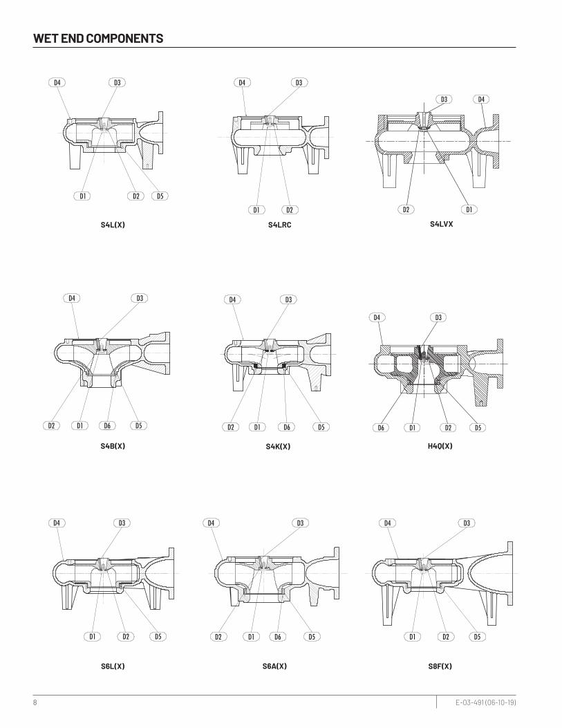
WET END COMPONENTS
D5D6D1D2
D3D4
S4B(X) S4K(X) H4Q(X)
S4LRC
D3D4
D2 D1 D6 D5
D4 D3
D5D1 D2D6
D1 D2
D4 D3
D4
D1D2
D3
S4LVX
S6A(X)
S4L(X)
D4 D3
D5D6D1D2
D3D4
D5D2D1
D5D2D1
D3D4
S6L(X) S8F(X)
D3D4
D1 D2 D5

9 E-03-491 (06-10-19)
WET END PARTS LIST
Item # Description S4B(X) S4L(X) S4LRC 3450 RPM
S4LRC/S4LVX S6A(X) S6L(X) S8F(X) S4K(X) H4Q(X)
D1 SCREW – HHC 5/8-11 UNF x 1-1/4 005700181 005700181 005700181 005700181 005700181 005700181 005700181 005700181 005700181
D2 WASHER – IMPELLER 019450001 019450001 019450001 019450001 019450001 019450001 019450001 019450001 019450001
D3 KEY – 1/3" SQUARE 028550081 028550081 028550031 028550081 028550081 028550081 028550081 028550081 028550081
D4 VOLUTE 136910002 089190015 107830002 107830002 136930012 089180015 089260025 137190002 151520015
D5 RING – WEAR 136900003 042890023
REFERTO
FACTORY
— 136950003 042890023 042890023 136900003 136900033
D6 SCREW MACH. 048200101 (3) — —048200111
(4)— — 048200101 (3)
000110021 (2)
IMPELLER
7.38" — — 110430162 — — — — —
7.88" — — 110430152 — — — — —
8.38" — 025940242 — — 025940242 025940242 — —
8.63" — 025940292 110430132 — — 025940292 137200242 —
8.81" — 025940232 — — — — 137200362 —
9" 136920132 025940022 — 136940132 025940022 025940022 137200132 151510062
9.25" 136920122 025940032 110430122 136940122 025940032 025940032 137200122 151510122
9.5" 136920112 025940042 — 136940112 025940042 025940042 137200112 151510052
9.63" — 025940302 — 136940232 025940302 025940302 137200282 —
9.81" 136920382 025940192 — — 025940192 — — —
10" 136920092 025940062 110430042 136940092 — — 137200092 151510042
10.18" — — — — 025940212 025940212 — 151510102
10.25" 136920082 025940072 — — 025940072 025940072 137200082 —
10.31" — — 110430112 — — — 137200342 —
10.38" 136920152 025940162 — 136940182 025940162 025940162 137200212 —
10.5" 136920072 025940082 — 136940072 025940082 025940082 137200072 151510032
10.85" — 025940492 — — 025940492 025940492 — —
11" 136920052 025940102 — 136940052 025940102 — 137200052 151510022
11.25" 136920042 025940422 110430082 136940042 025940112 025940112 137200042 151510092
11.38" 136920182 025940202 — 136940292 025940202 025940202 137200322 151510162
11.5" 136920032 025940122 110430012 136940032 025940122 025940122 137200032 151510012
11.63" 136920202 025940182 — 136940332 025940122 025940122 137200172 151510182
11.88" 136920232 025940002 — — 025940002 025940002 137200302 —
12" 136920012 025940352 110430002 136940012 025940352 025940352 137200012 151510002
For use with product built with motors from U.S. Electrical Motors (USEM).
10 E-03-491 (06-10-19)
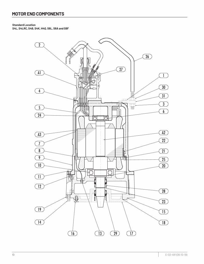
MOTOR END COMPONENTS
2
A1
4
5
24
A3
7
8
9
10
11
12
19
14
16 13 29 17
18
15
23
28
2025
21
22
A2
3
31
30
1
26
6
27
Standard Location S4L, S4LRC, S4B, S4K, H4Q, S6L, S6A and S8F

11 E-03-491 (06-10-19)
MOTOR END PARTS LIST
Fill oil to above the motor windings.
Notes: S — Parts in Seal Kit C — Parts in Carbide Seal Kit — Fill oil to above the motor windings.
Standard Location S4L, S4LRC, S4B, S4K, H4Q, S6L, S6A and S8F For use with product built with motors from U.S. Electrical Motors (USEM).
Motor Parts ListFor use with product built with motors from U.S. Electrical Motors (USEM).
hp VOLTAGE/ ph/RPM A1 BOXCONNECTION
A2ROTOR/ SHAFT
A3STATOR R RING SPACER
3–5 200/3/870 062370015 143990115 143992031 076650011
3–5 230-460/3/870 062370005 143990115 143990031 076650011
3–5 575/3/870 062370015 143990115 143996031 076650011
3–5 200/3/1150 062370015 144000115 144002031 076650121
3–5 230-460/3/1150 062370005 144000115 144000031 076650121
3–5 575/3/1150 062370015 144000115 144006031 076650121
7.5–10 200/3/1150 062370015 141500115 141502031 076650101
7.5–10 230-460/3/1150 062370005 141500115 141500031 076650101
7.5–10 575/3/1150 062370015 141500115 141506031 076650101
15 200/3/1150 062370035 141510115 151512031 076650051
15 230/3/1150 062370055 141510115 141510031 076650051
15 460/3/1150 062370005 141510115 141510031 076650051
15 575/3/1150 062370015 141510115 141516031 076650051
20 200/3/1750 062370035 141520115 141522031 076650041
20 230-460/3/1750 062370005 141520115 141520031 076650041
20 575/3/1750 062370015 141520115 141526031 076650041
25–30 200/3/1750 062370075 141530115 141532031 –
25–30 230/3/1750 062370055 141530115 141530031 –
25–30 460/3/1750 062370005 141530115 141530031 –
25–30 575/3/1750 062370015 141530115 141536031 –
40 230/3/1750 062370075 141530115 141540031 –
40 460/3/1750 062370005 141530115 141540031 –
40 575/3/1750 062370015 141530115 141546031 –
50 460/3/1750 062370055 141530115 141550031 –
50 575/3/1750 062370035 141530115 141556031 –
60 460/3/3450 062370075 143030115 143030031 076650011
60 575/3/3450 062370035 143030115 143036031 076650011
Ref.No.
PartNo.
PartDescription Qty.
1 05454A027 WASHER – LOCK 5/8 SST 2
2 05876A103 O-RING – 1/8 x 3.374 I.D. SC 1
3 05454A030 WASHER – LOCK 3/4 SST 4
4 05876A067 O-RING – 1/8 x 7.234 I.D. SC 1
5 12672A001 CONNECTOR – WIRE 3
6 08565A027 BEARING – BALL – UPPER 1
7 060000211 WIRE W/TERMINAL 1
8 012720001 TUBING – INSULATING 1
9 048320032 HOUSING – MOTOR 1
10 000650321 BEARING – BALL – LOWER 1
11 005680061 SCREW – HHC 1/2-13 x 1-1/2 8
12 001500251 O-RING – 1/8 x 11.484 I.D. SC 1
13 084720035 SEAL FAILURE ASSY. 1
14 19105A033 SCREW – HHC 5/8-11 x 1-1/2 8
15 001500261 O-RING – 1/8 x 11.984 I.D. SC 1
Ref.No.
PartNo.
PartDescription Qty.
16 029210011 SCREW – HHC 1/2-13 x 1-1/4 4
17 025960032 PLATE – SEAL 1
18 05876A135 O-RING – 1/8 x 9.734 I.D. SC 1
19 025950042 HOUSING – BEARING/SEAL 1
20 009750251 RING – RETAINING 1
21 026030003 RING – STATOR RETAINING 1
22 065790031 KEY SQ – 1/4" x 1.19 1
23 009750061 RING – RETAINING 1
24 000640061 SPRING – BEARING ADJ. 2
25 001780051 SCREW – HEX SOC. 5/16 x 1-1/2 8
26 151751001 LIFTING BAIL 1
27
152770305 35' CORD ASSEMBLY – 10-4 1
152770315 35' CORD ASSEMBLY – 8-4 SOOW 1
152770325 35' CORD ASSEMBLY – 8-4 1
152770335 35' CORD ASSEMBLY – 6-4 1
Ref.No.
PartNo.
PartDescription Qty.
152770345 35' CORD ASSEMBLY – 4-4 1
152770355 35' CORD ASSEMBLY – 2-4 1
28 019570001CARBON CERAMIC/
BUNA-N – UPPERS 1
29 019570001CARBON CERAMIC (STD)/
BUNA-N – LOWERS 1
019570021 CARBIDE (OPT) – LOWER C 1
30 19109A080 NUT – HEX 3/4 SST 4
31 151740001 BRACKET – MOUNTING 2

12 E-03-491 (06-10-19)
MOTOR END COMPONENTS
Hazardous Location S4LX, S4LVX, S4BX, S4KX, H4QX, S6LX, S6AX and S8FX
19
A5
18
17
11
14
A3
16
15
22
13
1221109537
A2
A6
20
A4
A1
1
2
4
3
8
6
13 E-03-491 (06-10-19)
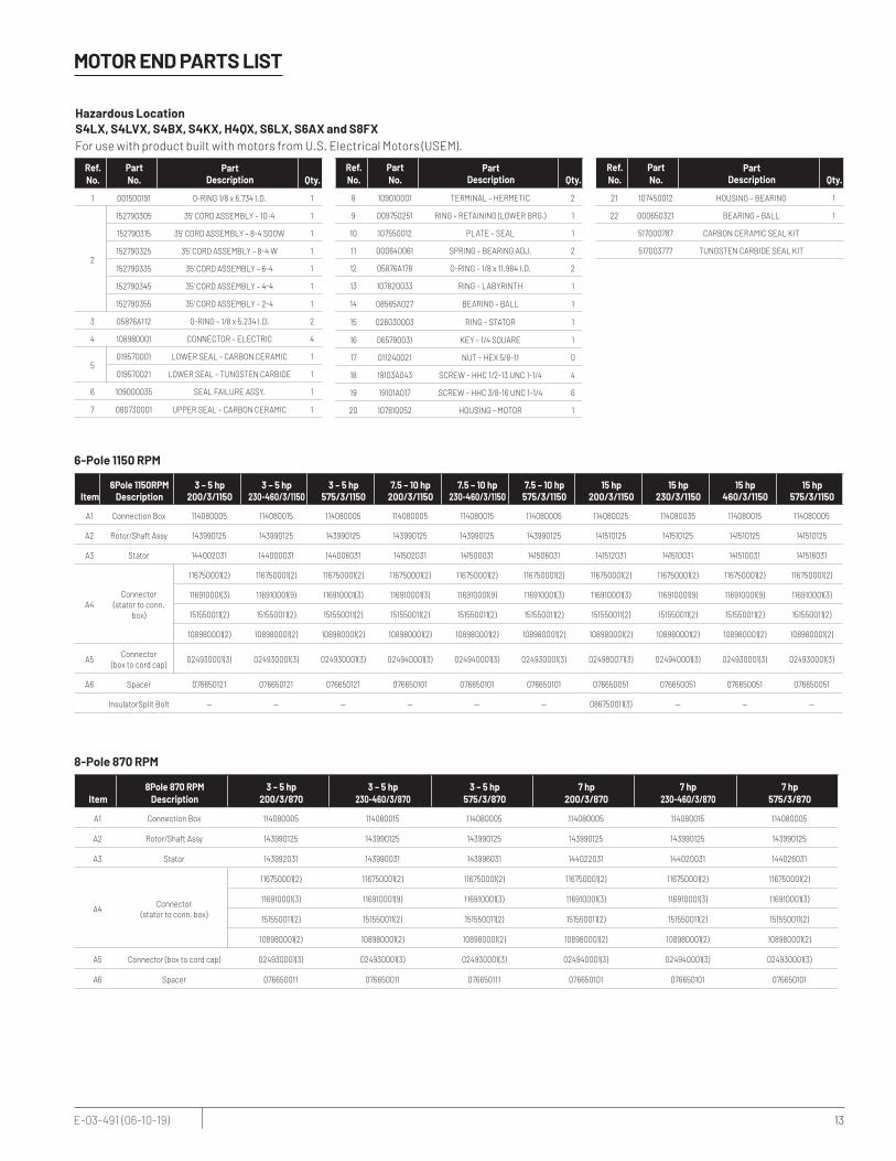
MOTOR END PARTS LIST
Ref.No.
PartNo.
PartDescription Qty.
1 001500191 0-RING 1/8 x 6.734 I.D. 1
2
152790305 35' CORD ASSEMBLY – 10-4 1
152790315 35' CORD ASSEMBLY – 8-4 SOOW 1
152790325 35' CORD ASSEMBLY – 8-4 W 1
152790335 35' CORD ASSEMBLY – 6-4 1
152790345 35' CORD ASSEMBLY – 4-4 1
152790355 35' CORD ASSEMBLY – 2-4 1
3 05876A112 0-RING – 1/8 x 5.234 I.D. 2
4 108980001 CONNECTOR – ELECTRIC 4
5019570001 LOWER SEAL – CARBON CERAMIC 1
019570021 LOWER SEAL – TUNGSTEN CARBIDE 1
6 109000035 SEAL FAILURE ASSY. 1
7 080730001 UPPER SEAL – CARBON CERAMIC 1
Ref.No.
PartNo.
PartDescription Qty.
8 109010001 TERMINAL – HERMETIC 2
9 009750251 RING – RETAINING (LOWER BRG.) 1
10 107550012 PLATE – SEAL 1
11 000640061 SPRING – BEARING ADJ. 2
12 05876A178 O-RING – 1/8 x 11.984 I.D. 2
13 107820033 RING – LABYRINTH 1
14 08565A027 BEARING – BALL 1
15 026030003 RING – STATOR 1
16 065790031 KEY – 1/4 SQUARE 1
17 011240021 NUT – HEX 5/8-11 0
18 19103A043 SCREW – HHC 1/2-13 UNC 1-1/4 4
19 19101A017 SCREW – HHC 3/8-16 UNC 1-1/4 6
20 107810052 HOUSING – MOTOR 1
Ref.No.
PartNo.
PartDescription Qty.
21 107450012 HOUSING – BEARING 1
22 000650321 BEARING – BALL 1
517000787 CARBON CERAMIC SEAL KIT
517003777 TUNGSTEN CARBIDE SEAL KIT
6-Pole 1150 RPM
Item6Pole 1150RPM
Description3 – 5 hp
200/3/11503 – 5 hp
230-460/3/11503 – 5 hp
575/3/11507.5 – 10 hp
200/3/11507.5 – 10 hp
230-460/3/11507.5 – 10 hp
575/3/115015 hp
200/3/115015 hp
230/3/115015 hp
460/3/115015 hp
575/3/1150
A1 Connection Box 114080005 114080015 114080005 114080005 114080015 114080005 114080025 114080035 114080015 114080005
A2 Rotor/Shaft Assy 143990125 143990125 143990125 143990125 143990125 143990125 141510125 141510125 141510125 141510125
A3 Stator 144002031 144000031 144006031 141502031 141500031 141506031 141512031 141510031 141510031 141516031
A4Connector
(stator to conn. box)
116750001(2) 116750001(2) 116750001(2) 116750001(2) 116750001(2) 116750001(2) 116750001(2) 116750001(2) 116750001(2) 116750001(2)
116910001(3) 116910001(9) 116910001(3) 116910001(3) 116910001(9) 116910001(3) 116910001(3) 116910001(9) 116910001(9) 116910001(3)
151550011(2) 151550011(2) 151550011(2) 151550011(2) 151550011(2) 151550011(2) 151550011(2) 151550011(2) 151550011(2) 151550011(2)
108980001(2) 108980001(2) 108980001(2) 108980001(2) 108980001(2) 108980001(2) 108980001(2) 108980001(2) 108980001(2) 108980001(2)
A5Connector
(box to cord cap)024930001(3) 024930001(3) 024930001(3) 024940001(3) 024940001(3) 024930001(3) 024980071(3) 024940001(3) 024930001(3) 024930001(3)
A6 Spacer 076650121 076650121 076650121 076650101 076650101 076650101 076650051 076650051 076650051 076650051
InsulatorSplit Bolt — — — — — — 086750011(3) — — —
8-Pole 870 RPM
Item8Pole 870 RPM
Description3 – 5 hp
200/3/8703 – 5 hp
230-460/3/8703 – 5 hp
575/3/8707 hp
200/3/8707 hp
230-460/3/8707 hp
575/3/870
A1 Connection Box 114080005 114080015 114080005 114080005 114080015 114080005
A2 Rotor/Shaft Assy 143990125 143990125 143990125 143990125 143990125 143990125
A3 Stator 143992031 143990031 143996031 144022031 144020031 144026031
A4Connector
(stator to conn. box)
116750001(2) 116750001(2) 116750001(2) 116750001(2) 116750001(2) 116750001(2)
116910001(3) 116910001(9) 116910001(3) 116910001(3) 116910001(3) 116910001(3)
151550011(2) 151550011(2) 151550011(2) 151550011(2) 151550011(2) 151550011(2)
108980001(2) 108980001(2) 108980001(2) 108980001(2) 108980001(2) 108980001(2)
A5 Connector (box to cord cap) 024930001(3) 024930001(3) 024930001(3) 024940001(3) 024940001(3) 024930001(3)
A6 Spacer 076650011 076650011 076650111 076650101 076650101 076650101
Hazardous Location S4LX, S4LVX, S4BX, S4KX, H4QX, S6LX, S6AX and S8FX For use with product built with motors from U.S. Electrical Motors (USEM).

14 E-03-491 (06-10-19)
MOTOR END PARTS LIST (CONTINUED)
4-Pole 1750 RPM
Item 4Pole 1750 RPM Description
25 hp 460/3/1750
25 hp 575/3/1750
30 hp 200/3/1750
30 hp 230/3/1750
30 hp 460/3/1750
30 hp 575/3/1750
40 hp 200/3/1750
A1 Connection Box 114080015 114080005 114080045 114080055 114080035 114080005 114080065
A2 Rotor/Shaft Assy 141530125 141530125 141530125 141530125 141530125 141530125 141530125
A3 Stator 141530031 141532031 141532031 141530031 141530031 141536031 141542031
A4Connector
(stator to conn. box)
116750001(2) 116750001(2) 116750001(2) 116750001(2) 116750001(2) 116750001(2) 116670001(2)
116910001(9) 116910001(3) 23394A001(3) 23394A001(9) 116910001(9) 116910001(3) 116910001(9)
151550011(2) 151550011(2) 151550011(2) 151550011(2) 151550011(2) 151550011(2) 151550011(2)
— — — — — — 151550031(3)
— — — — — — —
108980001(2) 108980001(2) 108980001(2) 108980001(2) 108980001(2) 108980001(2) 108980001(2)
A5Connector
(box to cord cap)024940001(6) 024940001(3) 024980071(3) 024980071(3) 024940001(6) 024940001(3) 024980071(3)
— — — 024980041(1) — — —
A6 Spacer — — — — — — —
InsulatorSplit Bolt— — 086750011(3) 086750011(3) — — 086750011(3)
— — 086750021(1) — — —
4-Pole 1750 RPM
Item 4Pole 1750 RPM Description
40 hp 230/3/1750
40 hp 460/3/1750
40 hp 575/3/1750
50 hp 230/3/1750
50 hp 460/3/1750
50 hp 575/3/1750
A1 Connection Box 114080055 114080035 114080025 114080065 114080055 114080025
A2 Rotor/Shaft Assy 141530125 141530125 141530125 141530125 141530125 141530125
A3 Stator 141540031 141540031 141546031 141550031 141550031 141556031
A4Connector
(stator to conn. box)
116750001(2) 116750001(2) 116750001(2) 116750001(2) 116750001(2) 116750001(2)
23394A001(9) 23394A001(9) 116910001(3) 116670001(3) 23394A001(9) 23394A001(3)
151550011(2) 151550011(2) 151550011(2) 151550011(2) 151550011(2) 151550011(2)
— — — 151550031(3) — —
— — — 116680001(1) — —
108980001(2) 108980001(2) 108980001(2) 108980001(2) 108980001(2) 108980001(2)
A5Connector
(box to cord cap)024980071(3) 024940001(3) 024940001(3) 024980071(3) 024940001(3) 024940001(3)
024980041(1) — — — 024980071(3) —
A6 Spacer — — — — — —
InsulatorSplit Bolt086750011(3) — — 086750011(3) 086750011(3) —
086750021(1) — — — — —
4-Pole 1750 RPM
Item 4Pole 1750 RPM Description
15 hp 575/3/1750
20 hp 200/3/1750
20 hp 230/3/1750
20 hp 460/3/1750
20 hp 575/3/1750
25 hp 200/3/1750
25 hp 230/3/1750
A1 Connection Box 114080005 114080025 114080035 114080035 114080005 114080045 114080055
A2 Rotor/Shaft Assy 141520125 141520125 141520125 141520125 141520125 141530125 141530125
A3 Stator 141526031 141522031 141520031 141520031 141526031 141532031 141530031
A4Connector
(stator to conn. box)
116750001(2) 116750001(2) 116750001(2) 116750001(2) 116750001(2) 116750001(2) 116750001(2)
116910001(3) 23394A001(3) 116910001(9) 116910001(9) 116910001(3) 23394A001(3) 116910001(9)
151550011(2) 151550011(2) 151550011(2) 151550011(2) 151550011(2) 151550011(2) 151550011(2)
108980001(2) 108980001(2) 108980001(2) 108980001(2) 108980001(2) 108980001(2) 108980001(2)
A5Connector
(box to cord cap)
024930001(3) 024980071(3) 024940001(1) 024940001(6) 024930001(3) 024980071(3) 024980071(3)
— — 024980051(3) — — — 024980041(1)
— — — — — — —
A6 Spacer 076650041 0766500418 0766500418 0766500418 0766500418 — —
InsulatorSplit Bolt— 06750011(3) 086750021(3) — — 086750011(3) 086750011(3)
— — — — — — 086750021(1)
Hazardous Location S4LX, S4LVX, S4BX, S4KX, H4QX, S6LX, S6AX and S8FXFor use with product built with motors from U.S. Electrical Motors (USEM).
4-Pole 1750 RPM
Item 4Pole 1750 RPM Description
10 hp 200/3/1750
10 hp 230-460/3/1750
10 hp 575/3/1750
15 hp 200/3/1750
15 hp 230/3/1750
15 hp 460/3/1750
A1 Connection Box 114080005 114080015 114080005 114080025 114080035 114080015
A2 Rotor/Shaft Assy 141510125 141510125 141510125 141520125 141520125 141520125
A3 Stator 141522031 141520031 141526031 141522031 141520031 141520031
A4Connector
(stator to conn. box)
116750001(2) 116750001(2) 116750001(4) 116750001(2) 116750001(2) 116750001(2)
23394A001(3) 116910001(9) 116910001(3) 23394A001(3) 116910001(9) 116910001(9)
151550011(2) 151550011(2) 151550011(4) 151550011(2) 151550011(2) 151550011(2)
108980001(2) 108980001(2) — 108980001(2) 108980001(2) 108980001(2)
A5Connector
(box to cord cap)
024940001(3) 024940001(4) 024930001(3) 024980051(3) 024940001(1) 024940001(6)
— — — — 024980041(3) —
— — — — — —
A6 Spacer 076650041 076650041 076650041 076650041 076650041 076650041
InsulatorSplit Bolt — — — 086750021(3) 086750021(3) —

15 E-03-491 (06-10-19)
WIRING DIAGRAMS
PROBE TEST RESISTORON HAZARDOUS LOCATION ONLY
PROBE TEST RESISTORON HAZARDOUS LOCATION ONLY
PROBE TEST RESISTORON HAZARDOUS LOCATION ONLY
––
–
PROBE TEST RESISTORON HAZARDOUS LOCATION ONLY
PROBE TEST RESISTORON HAZARDOUS LOCATION ONLY
PROBE TEST RESISTORON HAZARDOUS LOCATION ONLY
––
–
STANDARD LIMITED WARRANTY
Warranty Rev. 12/13
STANDARD LIMITED WARRANTY
Pentair Hydromatic* warrants its products against defects in material and workmanship for a period of 12 months from the date of shipment from Pentair Hydromatic or 18 months from the manufacturing date, whichever occurs first – provided that such products are used in compliance with the requirements of the Pentair Hydromatic catalog and technical manuals for use in pumping raw sewage, municipal wastewater or similar, abrasive-free, noncorrosive liquids.
During the warranty period and subject to the conditions set forth, Pentair Hydromatic, at its discretion, will repair or replace to the original user, the parts that prove defective in materials and workmanship. Pentair Hydromatic reserves the right to change or improve its products or any portions thereof without being obligated to provide such a change or improvement for prior sold and/or shipped units.
Start-up reports and electrical schematics may be required to support warranty claims. Submit at the time of start up through the Pentair Hydromatic website: http://forms.pentairliterature.com/startupform/startupform.asp?type=h. Warranty is effective only if Pentair Hydromatic authorized control panels are used. All seal fail and heat sensing devices must be hooked up, functional and monitored or this warranty will be void. Pentair Hydromatic will cover only the lower seal and labor thereof for all dual seal pumps. Under no circumstance will Pentair Hydromatic be responsible for the cost of field labor, travel expenses, rented equipment, removal/reinstallation costs or freight expenses to and from the factory or an authorized Pentair Hydromatic service facility.This limited warranty will not apply: (a) to defects or malfunctions resulting from failure to properly install, operate or maintain the unit in accordance with the printed instructions provided; (b) to failures resulting from abuse, accident or negligence; (c) to normal maintenance services and parts used in connection with such service; (d) to units that are not installed in accordance with applicable local codes, ordinances and good trade practices; (e) if the unit is moved from its original installation location; (f) if unit is used for purposes other than for what it is designed and manufactured; (g) to any unit that has been repaired or altered by anyone other than Pentair Hydromatic or an authorized Pentair Hydromatic service provider; (h) to any unit that has been repaired using non factory specified/OEM parts.
Warranty Exclusions: PENTAIR HYDROMATIC MAKES NO EXPRESS OR IMPLIED WARRANTIES THAT EXTEND BEYOND THE DESCRIPTION ON THE FACE HEREOF. PENTAIR HYDROMATIC SPECIFICALLY DISCLAIMS THE IMPLIED WARRANTIES OF MERCHANTABILITY AND FITNESS FOR ANY PARTICULAR PURPOSE.
Liability Limitation: IN NO EVENT SHALL PENTAIR HYDROMATIC BE LIABLE OR RESPONSIBLE FOR CONSEQUENTIAL, INCIDENTAL OR SPECIAL DAMAGES RESULTING FROM OR RELATED IN ANY MANNER TO ANY PENTAIR HYDROMATIC PRODUCT OR PARTS THEREOF. PERSONAL INJURY AND/OR PROPERTY DAMAGE MAY RESULT FROM IMPROPER INSTALLATION. PENTAIR HYDROMATIC DISCLAIMS ALL LIABILITY, INCLUDING LIABILITY UNDER THIS WARRANTY, FOR IMPROPER INSTALLATION. PENTAIR HYDROMATIC RECOMMENDS INSTALLATION BY PROFESSIONALS.
Some states do not permit some or all of the above warranty limitations or the exclusion or limitation of incidental or consequential damages and therefore such limitations may not apply to you. No warranties or representations at any time made by any representatives of Pentair Hydromatic shall vary or expand the provision hereof.
1101 MYERS PARKWAY 490 PINEBUSH ROAD, UNIT 4ASHLAND, OHIO 44805 CAMBRIDGE, ONTARIO, CANADA N1T 0A5PH: 855-274-8947 PH: 800-363-7867
WWW.HYDROMATIC.COM
*For a detailed list of where Pentair trademarks are registered, please visit www.pentair.com/en/registrations.html. Pentair trademarks and logos are owned by Pentair PLC. or its affiliates. Third party registered and unregistered trademarks and logos are the property of their respective owners. Because we are continuously improving our products and services, Pentair reserves the right to change specifications without prior notice. Pentair is an equal opportunity employer.
E-03-491 (06/10/19) ©2019 Pentair. All Rights Reserved.
1101 Myers Parkway | Ashland, OH 44805 | Ph: 855.274.8947 | pentair.com
(*Hazardous LocationMotor End)