Load
bre
ak s
wit
ches
INOSYS LBSLoad break switches for DC and PV applications160 to 630 A, up to 1500 VDC
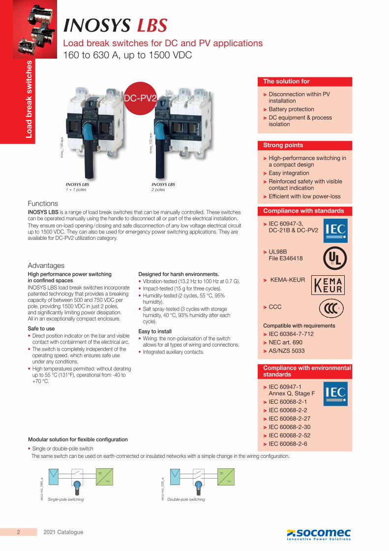
FunctionsINOSYS LBS is a range of load break switches that can be manually controlled. These switches can be operated manually using the handle to disconnect all or part of the electrical installation.They ensure on-load opening / closing and safe disconnection of any low voltage electrical circuit up to 1500 VDC. They can also be used for emergency power switching applications. They are available for DC-PV2 utilization category.
AdvantagesHigh performance power switching in confined spacesINOSYS LBS load break switches incorporate patented technology that provides a breaking capacity of between 500 and 750 VDC per pole, providing 1500 VDC in just 2 poles, and significantly limiting power dissipation. All in an exceptionally compact enclosure.
Safe to use • Direct position indicator on the bar and visible contact with containment of the electrical arc.
• The switch is completely independent of the operating speed, which ensures safe use under any conditions.
• High temperatures permitted: without derating up to 55 °C (131°F), operational from -40 to +70 °C.
Designed for harsh environments. • Vibration-tested (13.2 Hz to 100 Hz at 0.7 G). • Impact-tested (15 g for three cycles). • Humidity-tested (2 cycles, 55 °C, 95% humidity).
• Salt spray-tested (3 cycles with storage humidity, 40 °C, 93% humidity after each cycle).
Easy to install • Wiring: the non-polarisation of the switch allows for all types of wiring and connections.
• Integrated auxiliary contacts.
> High-performance switching in a compact design
> Easy integration > Reinforced safety with visible contact indication
> Efficient with low power-loss
Strong points
> IEC 60947-1 Annex Q, Stage F
> IEC 60068-2-1 > IEC 60068-2-2 > IEC 60068-2-27 > IEC 60068-2-30 > IEC 60068-2-52 > IEC 60068-2-6
Compliance with environmentalstandards
INOSYS LBS 2 poles
INOSYS LBS 1 + 1 poles
> Disconnection within PV installation
> Battery protection > DC equipment & process isolation
The solution for
• Single or double-pole switch The same switch can be used on earth-connected or insulated networks with a simple change in the wiring configuration.
+(-)
+(-)
Modular solution for flexible configuration
Single-pole switching Double-pole switchingsirc
o-m
c_08
4_a
sirc
o-m
c_02
6_a
inos
y_15
2.ep
s
inos
y_15
8.ep
s
DC-PV2
> IEC 60947-3, DC-21B & DC-PV2
> UL98B File E346418
> KEMA-KEUR
> CCC
Compatible with requirements
> IEC 60364-7-712 > NEC art. 690 > AS/NZS 5033
Compliance with standards
2 2021 Catalogue
INOSYS LBSLoad break switches for DC and PV applications
160 to 630 A, up to 1500 VDC
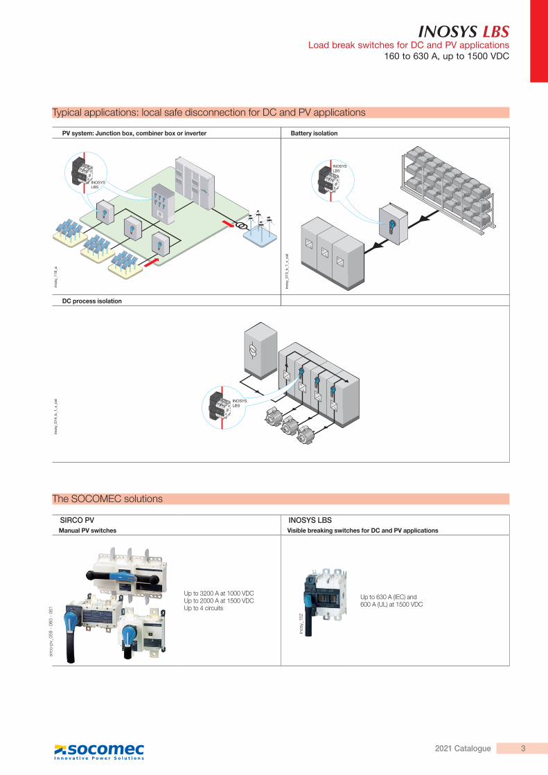
SIRCO PV INOSYS LBSManual PV switches Visible breaking switches for DC and PV applications
Up to 3200 A at 1000 VDCUp to 2000 A at 1500 VDCUp to 4 circuits
Up to 630 A (IEC) and600 A (UL) at 1500 VDC
PV system: Junction box, combiner box or inverter Battery isolation
DC process isolation
INOSYSLBS
Typical applications: local safe disconnection for DC and PV applications
The SOCOMEC solutions
inos
y_01
3_b_
1_x_
cat
inos
y_01
4_b_
1_x_
cat
sirc
o-pv
_059
- 0
60 -
061
inos
y_15
2
INOSYSLBS
INOSYSLBS
inos
y_11
8_a
32021 Catalogue
INOSYS LBSLoad break switches for DC and PV applications160 to 630 A, up to 1500 VDC
1
6
4
5
2
6
79
9
10
11
3
12
87
inos
y_16
8_a_
1_x_
cat.a
i
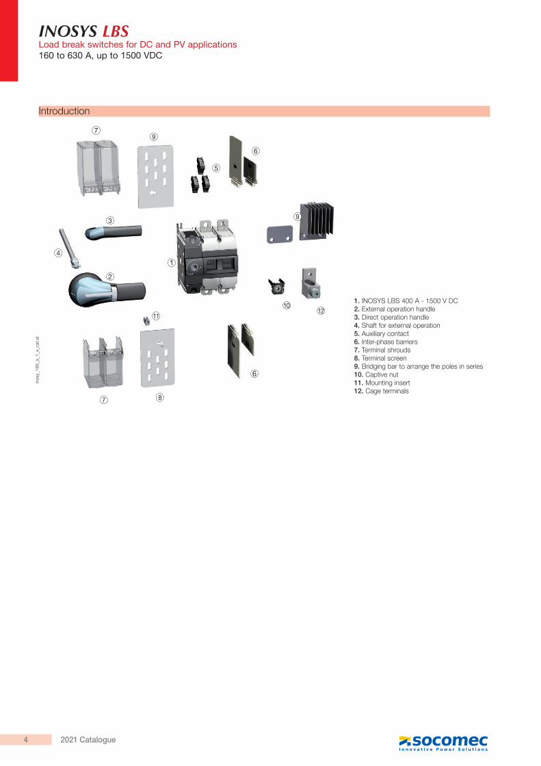
Introduction
1. INOSYS LBS 400 A - 1500 V DC2. External operation handle3. Direct operation handle4. Shaft for external operation5. Auxiliary contact6. Inter-phase barriers7. Terminal shrouds8. Terminal screen9. Bridging bar to arrange the poles in series10. Captive nut11. Mounting insert12. Cage terminals
4 2021 Catalogue
INOSYS LBSLoad break switches for DC and PV applications
160 to 630 A, up to 1500 VDC
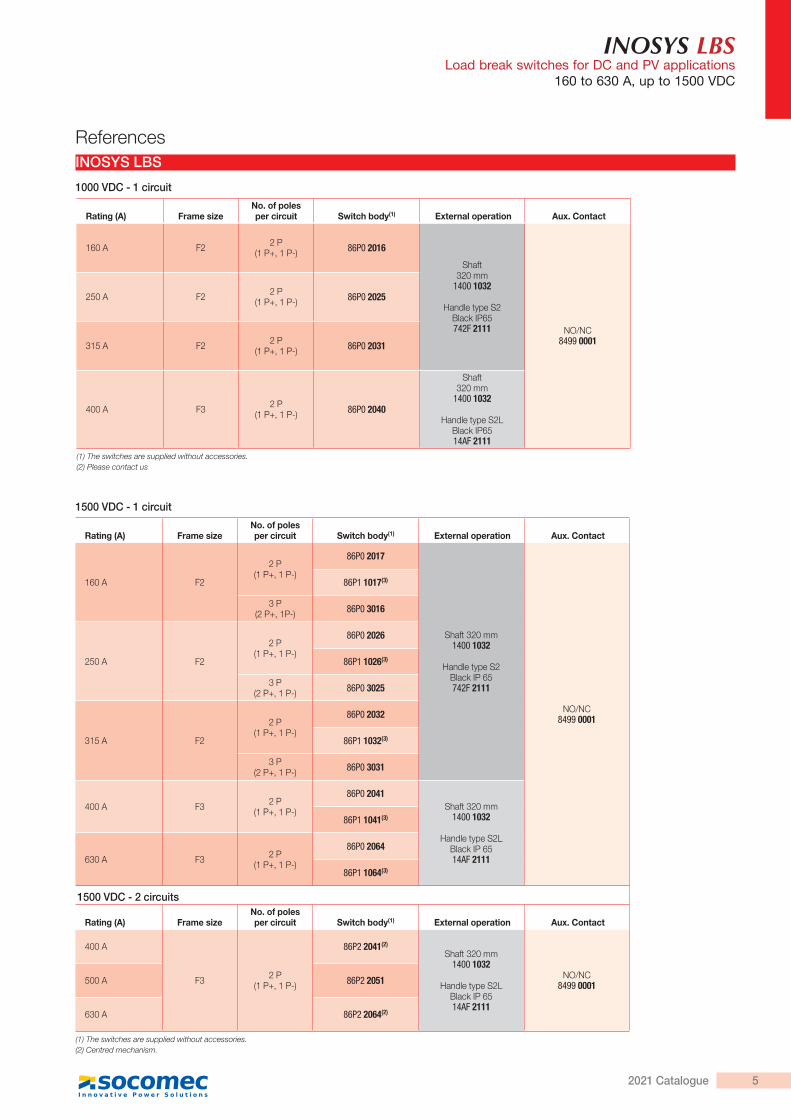
Rating (A) Frame sizeNo. of poles per circuit Switch body(1) External operation Aux. Contact
160 A F2 2 P (1 P+, 1 P-) 86P0 2016
Shaft320 mm
1400 1032
Handle type S2Black IP65742F 2111 NO/NC
8499 0001
250 A F2 2 P (1 P+, 1 P-) 86P0 2025
315 A F2 2 P (1 P+, 1 P-) 86P0 2031
400 A F3 2 P (1 P+, 1 P-) 86P0 2040
Shaft320 mm
1400 1032
Handle type S2LBlack IP6514AF 2111
(1) The switches are supplied without accessories.(2) Please contact us
INOSYS LBS
1000 VDC - 1 circuit
1500 VDC - 1 circuit
References
Rating (A) Frame sizeNo. of poles per circuit Switch body(1) External operation Aux. Contact
160 A F2
2 P (1 P+, 1 P-)
86P0 2017
Shaft 320 mm1400 1032
Handle type S2Black IP 65 742F 2111
NO/NC8499 0001
86P1 1017(3)
3 P (2 P+, 1P-) 86P0 3016
250 A F2
2 P (1 P+, 1 P-)
86P0 2026
86P1 1026(3)
3 P (2 P+, 1 P-) 86P0 3025
315 A F2
2 P (1 P+, 1 P-)
86P0 2032
86P1 1032(3)
3 P (2 P+, 1 P-) 86P0 3031
400 A F3 2 P (1 P+, 1 P-)
86P0 2041Shaft 320 mm
1400 1032
Handle type S2LBlack IP 6514AF 2111
86P1 1041(3)
630 A F3 2 P (1 P+, 1 P-)
86P0 2064
86P1 1064(3)
1500 VDC - 2 circuits
Rating (A) Frame sizeNo. of poles per circuit Switch body(1) External operation Aux. Contact
400 A
F3 2 P (1 P+, 1 P-)
86P2 2041(2)
Shaft 320 mm1400 1032
Handle type S2LBlack IP 6514AF 2111
NO/NC8499 0001500 A 86P2 2051
630 A 86P2 2064(2)
(1) The switches are supplied without accessories.(2) Centred mechanism.
52021 Catalogue
INOSYS LBSLoad break switches for DC and PV applications160 to 630 A, up to 1500 VDC
Accessories
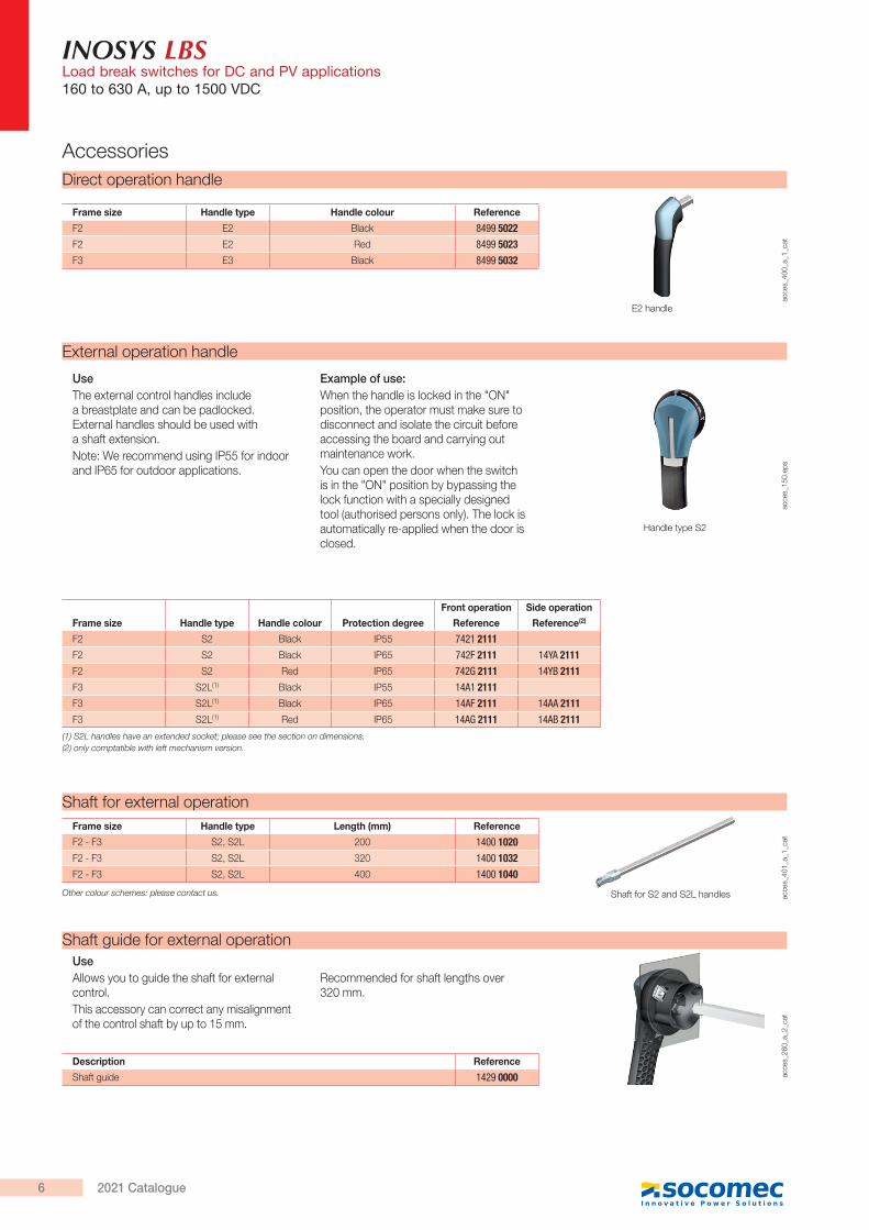
External operation handle
UseThe external control handles include a breastplate and can be padlocked. External handles should be used with a shaft extension.Note: We recommend using IP55 for indoor and IP65 for outdoor applications.
Example of use:When the handle is locked in the "ON" position, the operator must make sure to disconnect and isolate the circuit before accessing the board and carrying out maintenance work.You can open the door when the switch is in the "ON" position by bypassing the lock function with a specially designed tool (authorised persons only). The lock is automatically re-applied when the door is closed.
acce
s_15
0.ep
s
Handle type S2
Frame size Handle type Handle colour Protection degree
Front operation Side operation
Reference Reference(2)
F2 S2 Black IP55 7421 2111F2 S2 Black IP65 742F 2111 14YA 2111F2 S2 Red IP65 742G 2111 14YB 2111F3 S2L(1) Black IP55 14A1 2111F3 S2L(1) Black IP65 14AF 2111 14AA 2111F3 S2L(1) Red IP65 14AG 2111 14AB 2111
(1) S2L handles have an extended socket; please see the section on dimensions.(2) only comptatible with left mechanism version.
Direct operation handle
acce
s_40
0_a_
1_ca
t
E2 handle
Frame size Handle type Handle colour Reference
F2 E2 Black 8499 5022F2 E2 Red 8499 5023F3 E3 Black 8499 5032
Shaft guide for external operation
acce
s_26
0_a_
2_ca
t
UseAllows you to guide the shaft for external control.This accessory can correct any misalignment of the control shaft by up to 15 mm.
Recommended for shaft lengths over 320 mm.
Description Reference
Shaft guide 1429 0000
acce
s_40
1_a_
1_ca
t
Shaft for external operation
Other colour schemes: please contact us.
Frame size Handle type Length (mm) Reference
F2 - F3 S2, S2L 200 1400 1020F2 - F3 S2, S2L 320 1400 1032F2 - F3 S2, S2L 400 1400 1040
Shaft for S2 and S2L handles
6 2021 Catalogue
INOSYS LBSLoad break switches for DC and PV applications
160 to 630 A, up to 1500 VDC
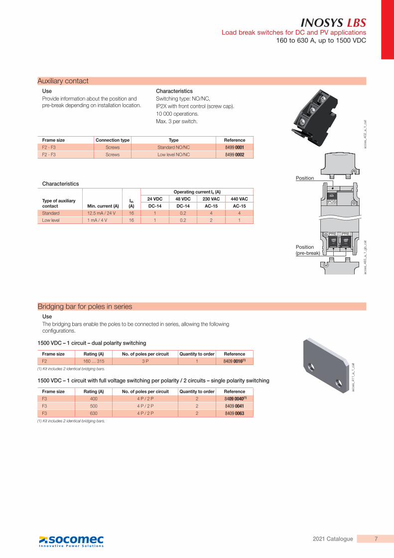
Auxiliary contactUseProvide information about the position and pre-break depending on installation location.
CharacteristicsSwitching type: NO/NC,IP2X with front control (screw cap).10 000 operations.Max. 3 per switch.
Characteristics
Type of auxiliary contact Min. current (A)
Ith (A)
Operating current Ie (A)
24 VDC 48 VDC 230 VAC 440 VAC
DC-14 DC-14 AC-15 AC-15
Standard 12.5 mA / 24 V 16 1 0.2 4 4
Low level 1 mA / 4 V 16 1 0.2 2 1
Position
Position(pre-break)
PRE PRE
POS
acce
s_40
2_a_
1_ca
tac
ces_
465_
a_1_
gb_c
at
Frame size Connection type Type Reference
F2 - F3 Screws Standard NO/NC 8499 0001F2 - F3 Screws Low level NO/NC 8499 0002
Bridging bar for poles in series
acce
s_41
1_a_
1_ca
t
UseThe bridging bars enable the poles to be connected in series, allowing the following configurations.
Frame size Rating (A) No. of poles per circuit Quantity to order Reference
F2 160 … 315 3 P 1 8409 0016(1)
(1) Kit includes 2 identical bridging bars.
Frame size Rating (A) No. of poles per circuit Quantity to order Reference
F3 400 4 P / 2 P 2 8409 0040(1)
F3 500 4 P / 2 P 2 8409 0041F3 630 4 P / 2 P 2 8409 0063
(1) Kit includes 2 identical bridging bars.
1500 VDC – 1 circuit – dual polarity switching
1500 VDC – 1 circuit with full voltage switching per polarity / 2 circuits – single polarity switching
72021 Catalogue
INOSYS LBSLoad break switches for DC and PV applications160 to 630 A, up to 1500 VDC
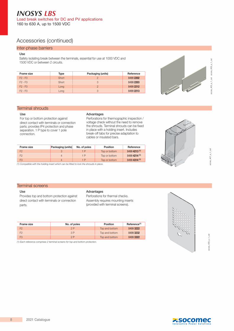
Inter-phase barriers
acce
s_40
5_a_
1_ca
t
UseSafety isolating break between the terminals, essential for use at 1000 VDC and 1500 VDC or between 2 circuits.
acce
s_40
6_a_
1_ca
t
Frame size Type Packaging (units) Reference
F2 - F3 Short 2 8499 2202F2 - F3 Short 3 8499 2203F2 - F3 Long 2 8499 2212F2 - F3 Long 3 8499 2213
acce
s_40
8_a_
1_ca
t
Terminal screensUseProvides top and bottom protection againstdirect contact with terminals or connectionparts.
AdvantagesPerforations for thermal checks.Assembly requires mounting inserts (provided with terminal screens).
Frame size No. of poles Position Reference(1)
F2 2 P Top and bottom 8499 3222F2 3 P Top and bottom 8499 3232F3 2 P Top and bottom 8499 3322
Terminal shrouds
acce
s_40
7_a_
1_ca
t
UseFor top or bottom protection againstdirect contact with terminals or connection parts; provides IP4 protection and phase separation. 1 P type to cover 1 pole connection.
AdvantagesPerforations for thermographic inspection /voltage check without the need to remove the shrouds. Terminal shrouds can be fixed in place with a holding insert. Includes break-off tabs for precise adaptation to cables or insulated bars.
Frame size Packaging (units) No. of poles Position Reference
F2 3 1 P Top or bottom 8499 4213 (1)
F2 4 1 P Top or bottom 8499 4214 (1)
F3 4 1 P Top or bottom 8499 4314 (1)
(1) Compatible with the holding insert which can be fitted to lock the shrouds in place.
(1) Each reference comprises 2 terminal screens for top and bottom protection.
Accessories (continued)
8 2021 Catalogue
INOSYS LBSLoad break switches for DC and PV applications
160 to 630 A, up to 1500 VDC
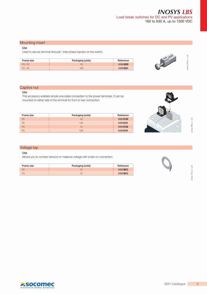
Mounting insert
acce
s_40
9_a_
1_ca
t
UseUsed to secure terminal shrouds / inter-phase barriers on the switch.
Frame size Packaging (units) Reference
F2 - F3 10 8499 6220F2 - F3 100 8499 6221
Voltage tapUseAllows you to connect sensors or measure voltage with a fast-on connection.
Frame size Packaging (units) Reference
F2 12 8499 9012F3 12 8499 9013
acce
s_41
2_a_
1_ca
t
Captive nut
acce
s_39
9_a_
1_ca
t
Frame size Packaging (units) Reference
F2 12 8499 6120F2 120 8499 6121F3 12 8499 6130F3 120 8499 6131
UseThis accessory enables simple one-sided connection to the power terminals. It can bemounted on either side of the terminal for front or rear connection.
92021 Catalogue
INOSYS LBSLoad break switches for DC and PV applications160 to 630 A, up to 1500 VDC
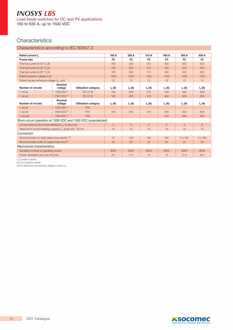
CharacteristicsCharacteristics according to IEC 60947-3
Rated current In 160 A 250 A 315 A 400 A 500 A 630 A
Frame size F2 F2 F2 F3 F3 F3
Thermal current at 40 °C (A) 160 250 315 400 500 630
Thermal current at 50 °C (A) 160 250 315 400 500 630
Thermal current at 60 °C (A) 160 250 315 400 500 630
Rated insulation voltage Ui (V) 1500 1500 1500 1500 1500 1500
Rated impulse withstand voltage Uimp (kV) 12 12 12 12 12 12
Number of circuitsNominal voltage Utilisation category Ie (A) Ie (A) Ie (A) Ie (A) Ie (A) Ie (A)
1 circuit 1000 VDC(1) DC-21 B 160 250 315 400 500 630
1 circuit 1500 VDC (2) DC-21 B 160 250 315 400 500 630
Number of circuitsNominal voltage Utilisation category Ie (A) Ie (A) Ie (A) Ie (A) Ie (A) Ie (A)
1 circuit 1000 VDC (1) PV2 - - - - - -
1 circuit 1500 VDC (2) PV2 160 250 315 400 500 630
2 circuits 1500 VDC (2) PV2 - - - 400 500 630
Short-circuit operation at 1000 VDC and 1500 VDC (unprotected)Current rated as short-time withstand Icw 1s (kA rms) 5 5 5 8 8 8
Rated short-circuit breaking capacity Icm (peak kA) – 60 ms 10 10 10 10 10 10
ConnectionRecommended Cu rigid cable cross-section (3) 70 120 185 240 2 x 150 2 x 185
Recommended width of copper bars (mm) (3) 20 20 20 25 25 25
Mechanical characteristicsDurability (number of operating cycles) 8000 8000 8000 8000 8000 8000
Power dissipation per pole (W/pole) 4.5 11.2 13 13 21.6 30.2
(1) 2 poles in series.(2) 2 or 3 poles in series.(3) For aluminium connections, please contact us.
10 2021 Catalogue
INOSYS LBSLoad break switches for DC and PV applications
160 to 630 A, up to 1500 VDC
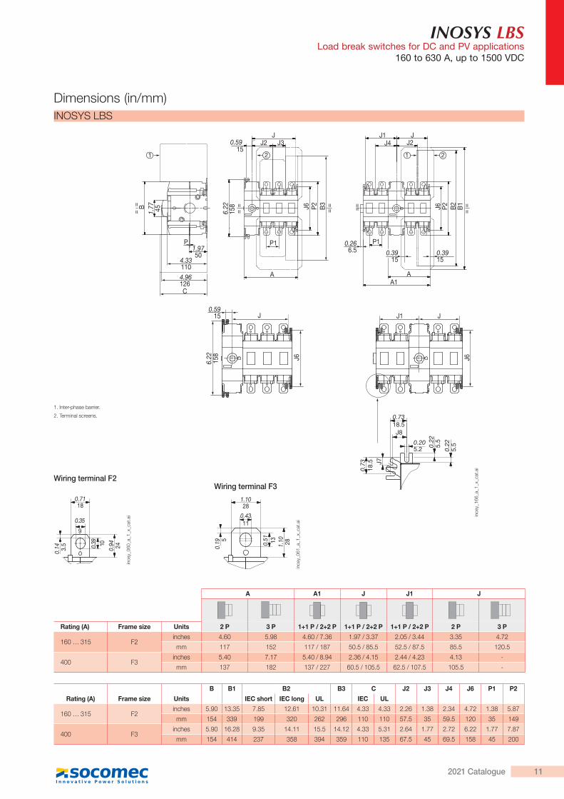
INOSYS LBS
1. Inter-phase barrier.
2. Terminal screens.
Wiring terminal F3
1.10 280.51 13
1.1028
0.4311
0.19 5
inos
y_06
1_a_
1_x_
cat.a
i
0.7118
0.35
9
0.14 3.5
0.94 240.39 10
inos
y_06
0_a_
1_x_
cat.a
i
Rating (A) Frame size Units
B B1 B2 B3 C J2 J3 J4 J6 P1 P2
IEC short IEC long UL IEC UL
160 … 315 F2inches 5.90 13.35 7.85 12.61 10.31 11.64 4.33 4.33 2.26 1.38 2.34 4.72 1.38 5.87
mm 154 339 199 320 262 296 110 110 57.5 35 59.5 120 35 149
400 F3inches 5.90 16.28 9.35 14.11 15.5 14.12 4.33 5.31 2.64 1.77 2.72 6.22 1.77 7.87
mm 154 414 237 358 394 359 110 135 67.5 45 69.5 158 45 200
A A1 J J1 J
Rating (A) Frame size Units 2 P 3 P 1+1 P / 2+2 P 1+1 P / 2+2 P 1+1 P / 2+2 P 2 P 3 P
160 … 315 F2inches 4.60 5.98 4.60 / 7.36 1.97 / 3.37 2.05 / 3.44 3.35 4.72
mm 117 152 117 / 187 50.5 / 85.5 52.5 / 87.5 85.5 120.5
400 F3inches 5.40 7.17 5.40 / 8.94 2.36 / 4.15 2.44 / 4.23 4.13 -
mm 137 182 137 / 227 60.5 / 105.5 62.5 / 107.5 105.5 -
0.3915
0.266.5
1.77 45
==
==
B
P1.9750
4.331104.96126C
6.22
158
P1
A
==J6 P2 B
3
JJ3 J2 0.59
15
JJ1J4 J2
J6 B1 =
=
== B2
P2
P1
AA1
22 11
6.22
158 J6
J0.59
15 JJ1
J6
J8
J7
0.73
18.5
0.7318.5
0.22
5.5
0.22
5.50.20
5.2
0.3915
inos
y_16
6_a_
1_x_
cat.a
iWiring terminal F2
Dimensions (in/mm)
112021 Catalogue
INOSYS LBSLoad break switches for DC and PV applications160 to 630 A, up to 1500 VDC
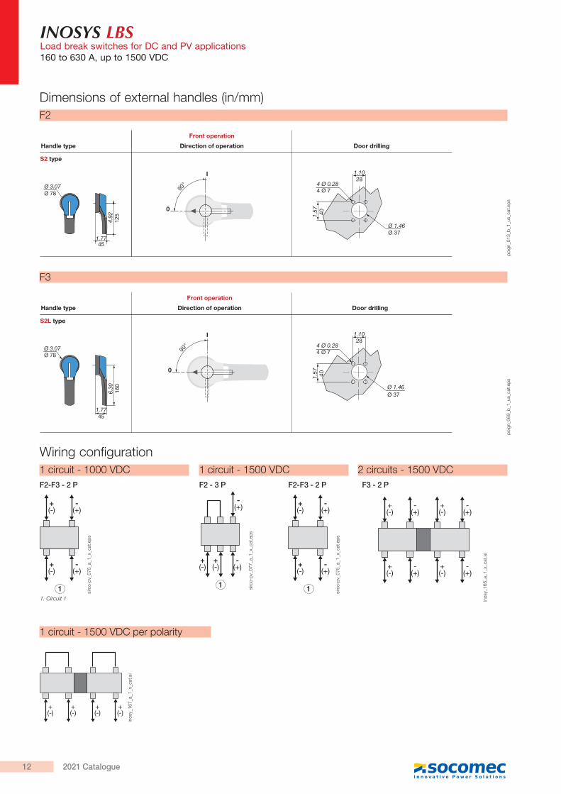
F2
F3
Dimensions of external handles (in/mm)
Direction of operation Door drillingHandle type
Front operation
S2 type
90°
I
0
Ø 3.07Ø 78
4.92
125
1.7745
1.57 40
4 Ø 0.284 Ø 7
Ø 1.46Ø 37
1.1028
poig
n_01
3_b_
1_us
_cat
.eps
Direction of operation Door drillingHandle type
Front operation
S2L type
90°
I
0
1.57 40
4 Ø 0.284 Ø 7
Ø 1.46Ø 37
1.1028
Ø 3.07Ø 78
1.7745
6.30
160
poig
n_06
9_b_
1_us
_cat
.eps
Wiring configuration1 circuit - 1000 VDC 1 circuit - 1500 VDC 2 circuits - 1500 VDCF2-F3 - 2 P F2-F3 - 2 P F3 - 2 PF2 - 3 P
1. Circuit 1
+(-)
-(+)
1
+(-)
-(+)
sirc
o-pv
_075
_a_1
_x_c
at.e
ps
+(-)
-(+)
1
+(-)
-(+)
sirc
o-pv
_075
_a_1
_x_c
at.e
ps
1
-(+)
+(-)
+(-)
-(+)
sirc
o-pv
_077
_a_1
_x_c
at.e
ps
+(-)
-(+)
+(-)
-(+)
+(-)
-(+)
+(-)
-(+)
inos
y_16
5_a_
1_x_
cat.a
i
1 circuit - 1500 VDC per polarity
+(-)
-(+)
+(-)
-(+)
+(-)
-(+)
+(-)
-(+)
+(-)
+(-)
+(-)
+(-)
inos
y_16
7_a_
1_x_
cat.a
i
12 2021 Catalogue
INOSYS LBSLoad break switches for DC and PV applications
160 to 630 A, up to 1500 VDC
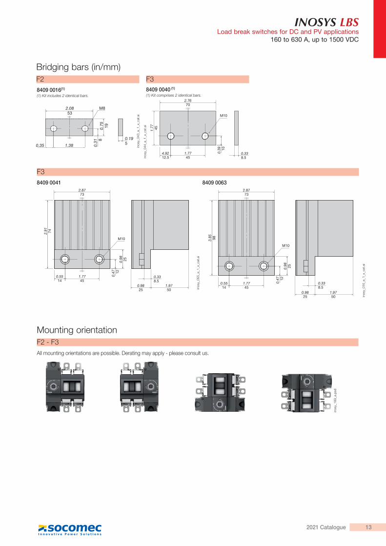
F28409 0016(1)
(1) Kit includes 2 identical bars.0.
75 19
0.31 8
1.3835
M8
0.359
0.195
2.0853
inos
y_04
3_a_
1_x_
cat.a
i
Mounting orientationF2 - F3All mounting orientations are possible. Derating may apply - please consult us.
inos
y_16
9_a.
psd
Bridging bars (in/mm)
F3
F38409 0040 (1)
(1) Kit comprises 2 identical bars.
8409 0041 8409 0063
M10
2.7670
4.9212.5
1.7745
1.77 45
0.39 10
0.338.5in
osy_
044_
a_1_
x_ca
t.ai
M10
1.9750
2.8773
0.5514
1.7745
2.91 74
0.98 25
0.47 12
0.9825
0.338.5
inos
y_05
5_a_
1_x_
cat.a
i
M10
1.9750
2.8773
0.5514
1.7745
3.85 98
0.98 25
0.47 12
0.9825
0.338.5
inos
y_01
6_a_
1_x_
cat.a
i
132021 Catalogue