GUIDELINES ON
SYNTHETIC MOORING LINES
DECEMBER 2001
IALA / AISM – 20ter rue Schnapper – 78100 Saint Germain en Laye – France Tel : +33 1 34 51 70 01 – Fax : +33 1 34 51 82 05 – E-mail : [email protected]
Internet : www.iala-aism.org

IALA Guidelines on Synthetic Mooring Lines
ii
IALA Guidelines on Synthetic Mooring Lines
iii
INTRODUCTION Synthetic rope moorings are being used by the offshore oil industry to replace chain and wire rope mooring lines, primarily in very deep-water situations. At very deep sites the weight of chain cables would present buoyancy problems for the moored vessel or handling problems for the servicing vessel to lay or lift the moorings. Aids to Navigation Authorities such as the French and USA services have a number of composite synthetic rope/chain moorings in use. The Trinity House Lighthouse Service has some experience with trial moorings, the Finnish Service use rope to moor spar buoys and The Netherlands Service has made extensive trials with cord moorings. These Guidelines are based on information provided to the IALA Engineering Committee by the Lighthouse Services of the United States, Canada, the United Kingdom, the Netherlands and Finland.

IALA Guidelines on Synthetic Mooring Lines
iv
IALA Guidelines on Synthetic Mooring Lines
1
TABLE OF CONTENTS 1. ROPE CONSTRUCTION .................................................................................................3 2. TYPES OF FIBRE.............................................................................................................4
2.1 Nylon..........................................................................................................................4 2.2 Polyester.....................................................................................................................4 2.3 Polypropylene ............................................................................................................4 2.4 Advanced Fibres ........................................................................................................5
3. MIXED CONSTRUCTION...............................................................................................5 4. ROPE BUOY MOORINGS...............................................................................................5 5. MOORING DESIGN.........................................................................................................6 6. ROPE TERMINATIONS ..................................................................................................6 7. HYBRID ROPE/CHAIN MOORINGS .............................................................................7 8. TENSION LEG MOORINGS ...........................................................................................7 9. FAST WATER MOORINGS ............................................................................................7 10. HANDLING ROPE MOORINGS .................................................................................7
10.1 Deployment ................................................................................................................7 10.2 Recovery ....................................................................................................................8
11. SAFETY.........................................................................................................................8 12. ELASTIC MOORINGS .................................................................................................9 13. ANNEX A....................................................................................................................10

IALA Guidelines on Synthetic Mooring Lines
2
IALA Guidelines on Synthetic Mooring Lines
3
1. ROPE CONSTRUCTION
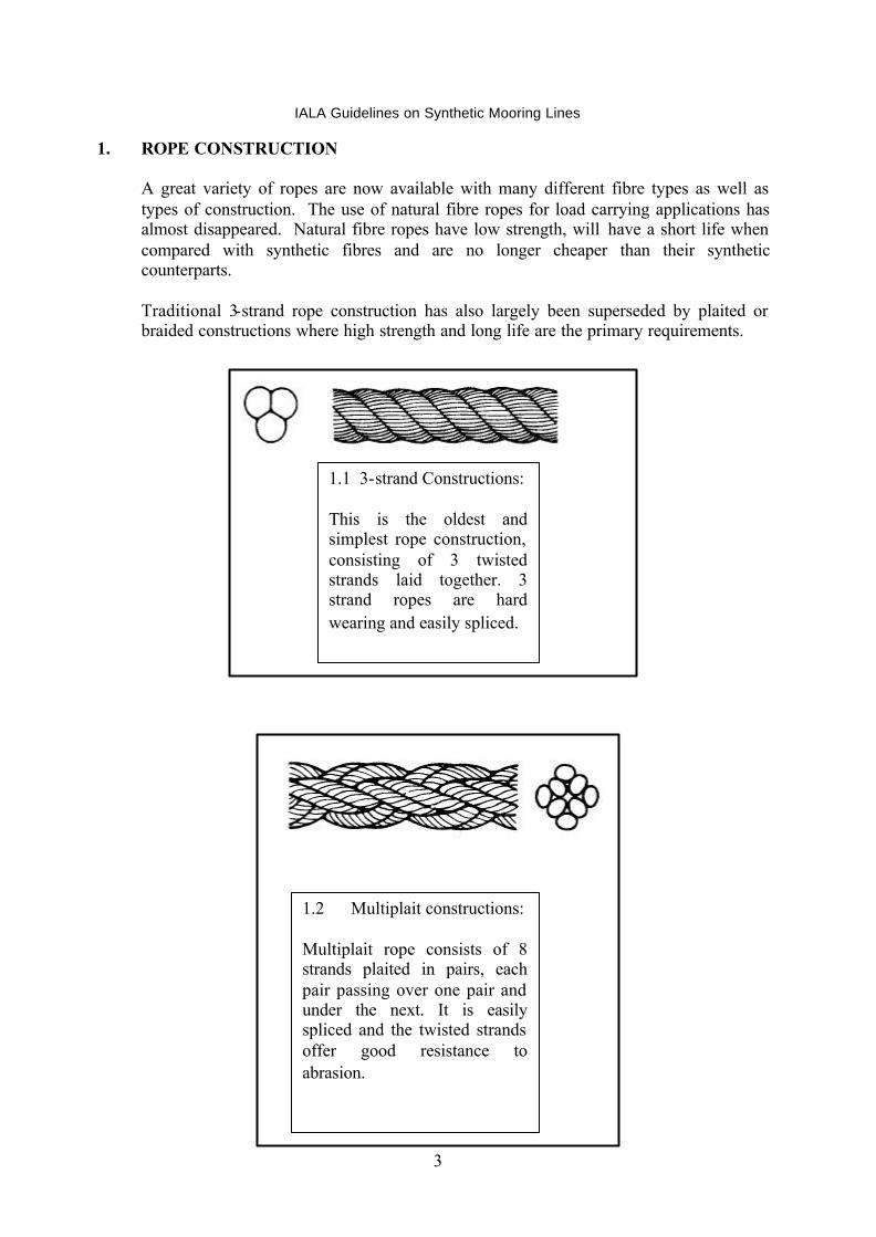
A great variety of ropes are now available with many different fibre types as well as types of construction. The use of natural fibre ropes for load carrying applications has almost disappeared. Natural fibre ropes have low strength, will have a short life when compared with synthetic fibres and are no longer cheaper than their synthetic counterparts. Traditional 3-strand rope construction has also largely been superseded by plaited or braided constructions where high strength and long life are the primary requirements.
1.1 3-strand Constructions: This is the oldest and simplest rope construction, consisting of 3 twisted strands laid together. 3 strand ropes are hard wearing and easily spliced.
1.2 Multiplait constructions: Multiplait rope consists of 8 strands plaited in pairs, each pair passing over one pair and under the next. It is easily spliced and the twisted strands offer good resistance to abrasion.
IALA Guidelines on Synthetic Mooring Lines
4
2. TYPES OF FIBRE
Modern rope materials utilise the following fibre groups:
2.1 Nylon
This provides high strength, elastic rope with good shock absorbing qualities. Some ultimate strength is lost due to water absorption if the rope is permanently immersed in water.
2.2 Polyester
This is widely used to construct high strength, low stretch ropes with good wear resistance and long life.
2.3 Polypropylene
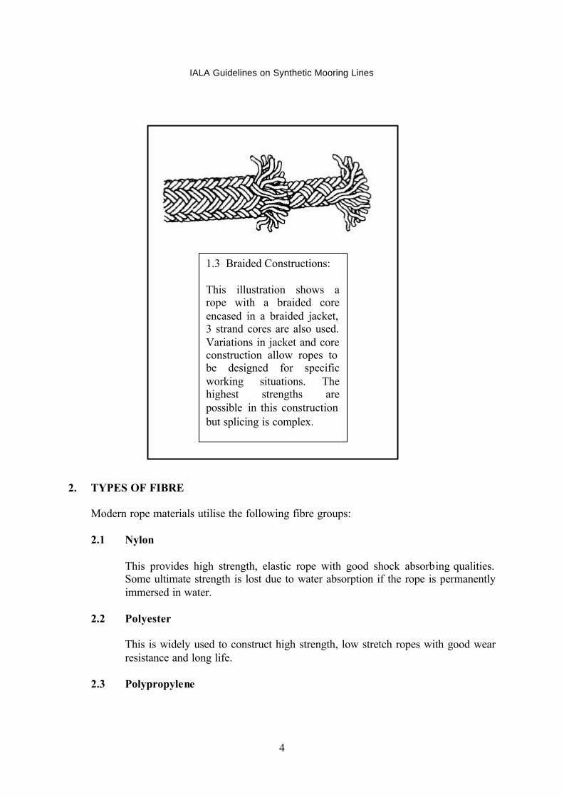
1.3 Braided Constructions: This illustration shows a rope with a braided core encased in a braided jacket, 3 strand cores are also used. Variations in jacket and core construction allow ropes to be designed for specific working situations. The highest strengths are possible in this construction but splicing is complex.

IALA Guidelines on Synthetic Mooring Lines
5
This has been used for cheap, general purpose rope, however recent developments in fibre manufacture and rope construction have resulted in moderate performance ropes, which are considerably cheaper than nylon or polyester.
2.4 Advanced Fibres
These include Aramid fibres (trade name Kevlar) and high modulus polyethylene (Spectra and Dynema) which have very high strengths associated with very low stretch. However, these are very expensive products being approximately three times the cost of nylon or polyester. Rope identification can be difficult as different manufacturers may use trade names for fibre type rather than generic names.
3. MIXED CONSTRUCTION
Large ropes, such as those used for ship mooring may be constructed from a mix of fibres to achieve particular performance parameters.
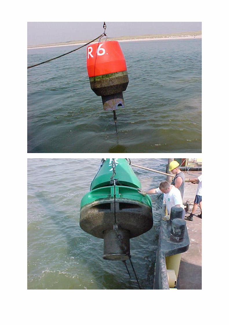
4. ROPE BUOY MOORINGS
The primary advantage of rope moorings is their light weight and elasticity when compared with normal chain moorings. Modern ropes can easily match the strength of steel chain and experience has shown that a similar or better working life than chain can be achieved if chafe is carefully avoided. The conventional chain mooring utilises energy absorption of the chain catenary to absorb much of the wind and wave energy acting on the buoy and prevent this being transferred to the sinker or anchor. The elasticity of the rope performs a similar function and choosing a suitable combination of fibre type and rope construction can optimise this energy absorption. Chafe and cutting are the greatest dangers to a rope mooring. It is easily demonstrated that a sharp knife will rapidly cut through a piece of rope and any sharp edges presented by rocks, sea shells or the servicing ships own capstan can rapidly cause permanent damage to the surface of the rope. Allowing the rope to slip on the drum of a capstan or pulling it through an unsuitable fairlead may not only result in abrasive damage but also in localised heating such that the surface fibres of the rope may melt, resulting in significant weakening. Rope does not suffer abrasive damage from sand particles in suspension in the water as do the bearing points of chain links resulting in rapid chain wear.

IALA Guidelines on Synthetic Mooring Lines
6
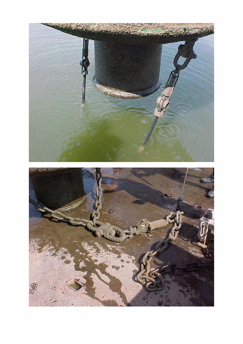
5. MOORING DESIGN The mooring must be designed so that the rope is never in contact with the buoy body or tail tube and is never in contact with the sea bed (although this may not be a problem in areas with soft, muddy bottoms). These criteria can be achieved in a normal buoy mooring by utilising a ground chain that absorbs the wear on the sea bed to which a rope “riser” is attached. The rope “riser” component of the mooring is of such a length that even at the lowest tides the rope is never chaffing on the sea bed. The rope may be attached directly to the buoy if the mooring eye is in a suitable position such that the rope will always be clear of the buoy. In other cases a short length of chain (or bridle in the case of two mooring eyes) may be used to absorb any chafe. Cutting by trawl wires may also be a hazard in some areas where commercial fishing takes place. It may be possible to utilise chain in the part of the mooring that may be subject to abrasion from trawl wires. The decision on the size of rope to be used will depend on the load imparted by the buoy, due to wind/wave action and water velocity and the strength necessary to lift the sinker (or anchor). The method to be used to handle the rope may also influence the size of rope chosen.
6. ROPE TERMINATIONS
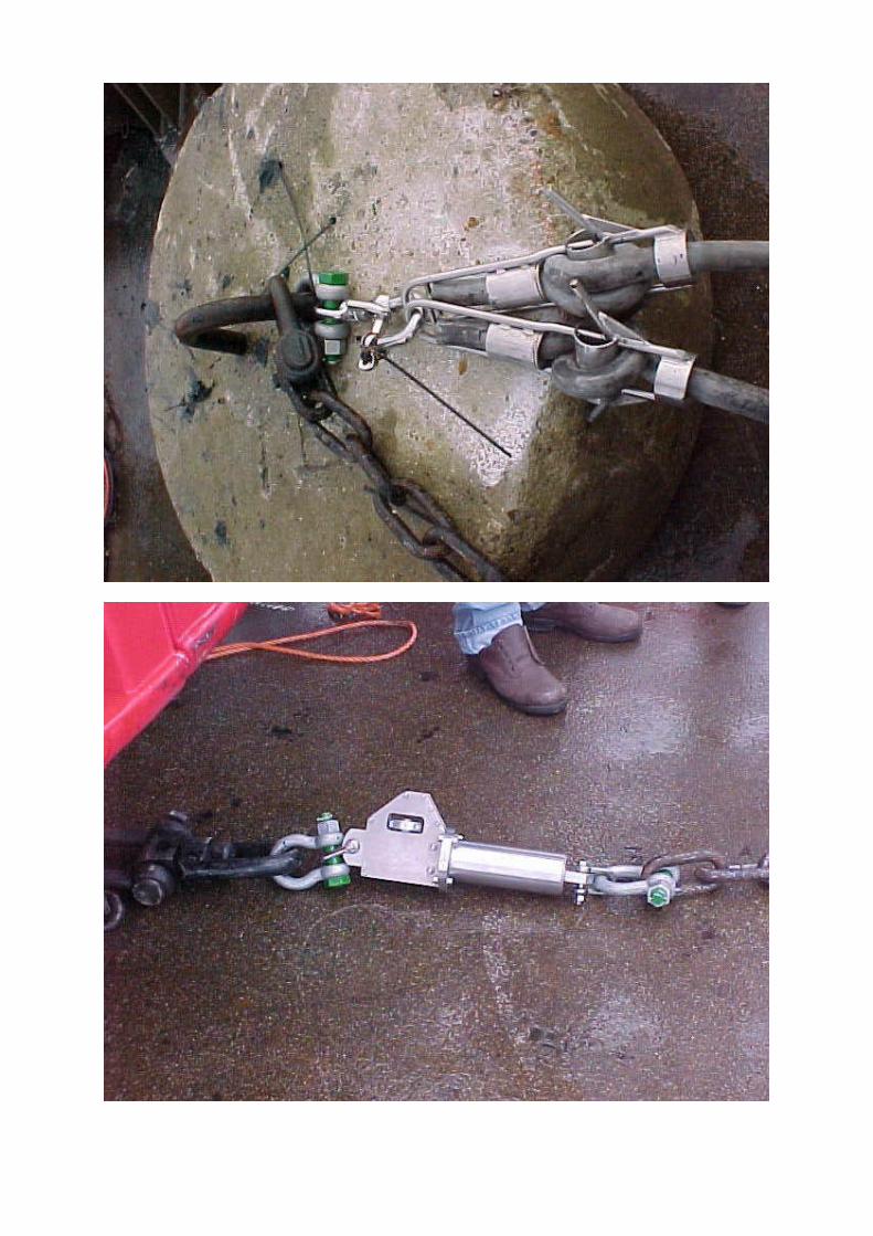
6.1 Thimbles
The use of fibre rope rather than wire rope for towing and mooring ships and oil rigs has lead to the development of thimbles which allow ropes carrying very high loads to be shackled to chain or mooring eyes without damaging the rope fibres. These thimbles completely enclose the rope leaving no unprotected rope surface to chafe against the joining shackle. They may be fabricated from steel tube, made in cast iron, or moulded from high strength plastic. Movement of the rope within the thimble can be further prevented by filling the thimble with a flexible resin system (usually polyurethane), however opinions differ as to the need for this process.
6.2 Splices
The modern rope constructions, i.e. braided and plaited constructions, both allow high strength splices to be made when the rope has been installed around the thimble. It should be noted that detailed splicing information must be obtained from the rope manufacturer and that these instructions have to be followed precisely in order to retain the majority of the rope strength at the splice. Special

IALA Guidelines on Synthetic Mooring Lines
7
tools will be needed for splicing braided rope and training of those making the splices in any modern rope construction will be necessary.
7. HYBRID ROPE/CHAIN MOORINGS
One of the most successful applications of rope has been for the “riser” component of deep-water buoy moorings. The lighter weight of the rope component will allow a service standard buoy to be used at stations where the weight of an all chain mooring would sink the standard buoy or the lighter weight of the rope mooring may allow a smaller buoy to be used when compared with the size of buoy that would be required to support the chain mooring (providing daymark size and focal plane height are adequate). The buoy size is related to the size of the servicing craft and the reduction in buoy size may enable the use of a smaller servicing vessel. The design of the buoy being used must be carefully examined to ensure that the riding performance of the buoy is adequate if the rope mooring is used. Some buoy designs rely on chain weight to achieve positive stability.
8. TENSION LEG MOORINGS
Rope moorings are particularly suitable for tensioned mooring configurations such as spar buoys and resilient beacons, where the mooring goes directly from the buoy to the sinker and tension in the mooring line holds the buoy upright. The rope being in tension is not in danger of chafing on the seabed or on the buoy. This configuration has the advantage of maintaining the buoy precisely on station (i.e. there is no “swinging circle” as there is with a conventional mooring) but is only practical in areas with little tidal range or current. However, the mooring sinker or anchor will need to be considerably larger than that associated with a conventional catenary mooring.
9. FAST WATER MOORINGS
The United States Coast Guard has used rope moorings for buoys in fast flowing rivers. Here the particular advantage is the light weight of the mooring which helps reduce the tendency of the buoy to be submerged as the current drag on the buoy lifts more mooring off the river bed.
10. HANDLING ROPE MOORINGS
10.1 Deployment
When compared with chain, rope is light and easy to manually handle. The components for quite large moorings can be moved about onshore or on deck by hand. Moorings can be deployed by flaking the rope on deck (or in a flaking

IALA Guidelines on Synthetic Mooring Lines
8
box, large version of line throwing gun rope box). The buoy is placed in the water, the sinker and ground chain simply pushed overboard (or released by cutting lashings) and the rope will follow into the water.
10.2 Recovery
If the mooring is to be lifted for removal or inspection then two areas need special attention:
1. Any fairlead that the rope runs over must be of sufficient diameter for the
rope used, be of the roller type and present no sharp edges 2. The winch or capstan must be designed for handling rope and must not
allow the rope to slip on the winch drum when under load.
Conventional capstans as used for tensioning mooring warps etc., may be capable of recovering a rope mooring however their tendency to allow the rope to slip on the capstan drum will result in considerable heat being generated at the rope/drum interface which will result in serious damage to the rope. Successful techniques have been developed using large spooling winches where the rope is wound onto a large rotating drum. This technique is limited by the length of rope and hence the number of moorings that can be carried on the drum at any one time. The preferred method, where a large number of rope moorings are to be handled, is to use a specialised rope hauling winch. These can be installed at the vessel’s deck edge so that the rope can lead directly to the winch without a fairlead being required. The winch consists of an arrangement of large rubber wheels, which grip the rope without causing damage to the surface fibres. The rope usually only passes over a segment of hauling wheel rather than being wrapped around a drum and can thus be placed in, or removed from, the hauling winch as may be necessary. This type of winch placed on the deck edge also has the advantage that there is no rope under load passing across the vessel’s deck, which may present a serious hazard, should the rope break. The deep water mooring design used by the French authority ensures that the ground chain is sufficiently long so that as the rope part of the mooring is retrieved the tension in the rope will only be the weight of the ground chain being lifted. The weight of the sinker will not be felt until all the rope has been recovered and the vessel is lifting the chain part of the mooring.
11. SAFETY
It must be noted that the energy stored in the more elastic types of rope when under tension may be considerable and suitable precautions must be taken to ensure that no personnel will be in any area that may be swept by the end of a broken rope.
IALA Guidelines on Synthetic Mooring Lines
9
12. ELASTIC MOORINGS
Rope moorings will absorb some of the buoy’s energy due to the elasticity of the rope and prevent this energy being transferred to the sinker. Fully elastic moorings have been developed where all of the buoys’ motion is absorbed by an elastic cord which forms part of the mooring cable. The Canadian Coast Guard are trialing such a system where the mooring cord is of a composite braided construction which limits the extension of the elastic cord and slows the elastic recovery of the cord to prevent any “whiplash” effect should a break occur. Such moorings have been successfully used as part of tension leg moorings securing pontoons in marinas subject to wave action and wash from passing vessels. The Netherlands authority is using elastic cord cables to moor relatively small buoys in areas subject to wave action. The elastic moorings allow the use of a short cable and hence a limited swinging circle.
Annex A provides details of The Netherlands Authority’s experience with elastic moorings.

IALA Guidelines on Synthetic Mooring Lines
10
13. ANNEX A
Elastic mooring of navigation buoys in shallow water
H.P. Joosten, Datawell B.V., Zomerluststraat 4, 2012 LM Haarlem, The Netherlands S. Hoekstra, Directie Noordzee, Koopmanstraat 1, 2288 BC Rijswijk, The Netherlands
Recent improvements of navigation buoys have made wear of the mooring chain one of the weakest point of the complete system. The use of an elastic mooring for navigation buoys - common practice for over 40 years in the case of wave measuring buoys - constitutes a substantial improvement in life expectation. In the case of shallow water, the severe requirement on the maximum elongation of the elastic mooring is met by the combination of natural rubber and bollard terminals.
Introduction
With increasing life time of navigation buoys, it is the wear of the mooring chain that mainly determines the service interval for these systems. Grinding by sand contributes substantially to this chain wear. The sand grains get between the chain links when the mooring line is slack, and do their damage when it is tightened again. The ongoing wave movement causes the mooring line to be alternately under tension and without tension. Although tides and currents distribute this wear somewhat over the chain, it is better to prevent this wear altogether. A way to reduce the grinding is by keeping the mooring line continuously tight, thus keeping the grains out of the link spacings. This is achieved by putting in an elastic cord in the mooring line. Problem of shallow water
Designing an elastic cord mooring is a challenge especially in shallow water with a relatively large tidal amplitude. In these circumstances, the ratio of the maximum cord length - needed to keep the buoy visible at high tide - and the minimum cord length - needed to keep the line under tension at low tide - is very large. This large ratio constitutes a requirement on the maximum elongation of the elastic cord. In order to discuss this problem in quantitative terms, we introduce the symbol λ, denoting the ratio of the actual cord length at any moment and the initial cord length when being unstressed. An elongation of 100% is thus indicated by λ = 2, a 200% elongation by λ = 3, etc. The maximum elongation of a elastic cord is denoted by λmax. When we indicate the length ratio required by the circumstances as λreq, the problem is reformulated as finding a cord mooring for which λmax > λreq.
Let us consider a typical shallow water situation having a low tide depth of 2.5 m, a tidal cycle of 3.5 m and a maximum current of 1 m/s. In addition, a maximum wave height in the range of a few metres is assumed. In these circumstances, λreq is about 4. Traditional overbraided rubber cords cannot meet this requirement, since their λmax is only 2 [1]. A rubber cord with a loosely woven overbraid, sometimes used in open sea [2], does have a λmax of 4, however, in this case the wear problems are not solved but transferred to the rubber/braid strangles.
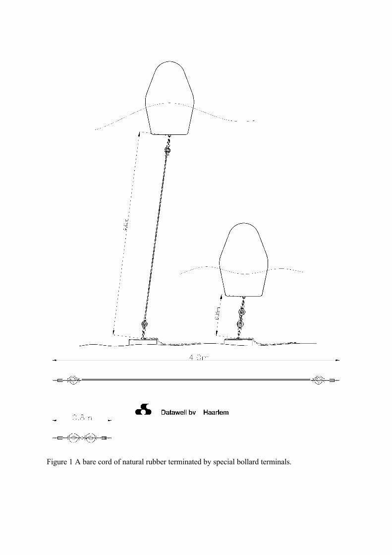
Figure 1 A bare cord of natural rubber terminated by special bollard terminals.
Solution
The proper choice in this situation is a bare cord of natural rubber, terminated by special bollard terminals, see Fig. 1. When terminated by the standard Datawell rubber cord terminals, the maximum elongation of the rubber itself is circa 4. However, since the bollard of the terminal holds a certain length of cord - that, when stressed, slips from the bollard and adds up to the cord length -, the effective λmax of the combination of cord and terminals is larger than this 4, and can in fact be as large as 5. The shorter the rubber cord is, the stronger is this positive bollard effect.
The elastic mooring line described above is basically a shortened version of the standard Datawell rubber cord used for over 40 years to moor (Directional) Waveriders and Wavecs [3]. Basically these buoys are motion sensors. They become wave sensors when enabled to follow the orbital waves movement. For this reason, an elastic cord is incorporated in the mooring line of these buoys. The size of the wave buoys ranges from 0.7 m diameter (spherical) to 2.5 m diameter (discuss shape). Standard lengths of the rubbercord are 15 and 30 m of rubber with a hardness of either 45 or 60 Shore A, depending on size of the buoy and required specification of the wave buoy.
The elegance of the Datawell rubber cord design is its simplicity. It consists of an arbitrary length of rubber and two stainless steel terminals which are easily mounted and removed from the rubber cord. Since the rubber cord is bare and solid, wear due to sand is principally impossible. Also, no fouling is encountered, since it cannot stick to the surface of the continuously oscillating cord. Finally, the fouling of the stainless steel bollard is prevented by the piece of the rubber cord at the terminal moving on and off the bollard.
The flexible mooring for navigation buoys serves basically the same purpose as the mooring for wave buoys: allowing the buoy to follow as much as possible the wave motion without getting off location. Often the elastic cord has been promoted by suppliers with the argument of shock absorption. However, also in properly chain-moored buoys no shocks show up. The craftsmanship and experience of the local light house authorities help them in determining the minimum chain length long enough to avoid the chain being tightly stretched between buoy and mooring stone.
This minimum chain length will always exceed the length of an optimally designed elastic mooring, making the latter preferable in terms of precise localization. It also suggests that the flexible mooring, though perhaps more expensive per unit length, could well be the most profitable when comparing complete designs. Apart from this reduction of initial expense, it is expected that inspection, maintenance and retrieval will occur less frequently, thus making the elastic mooring the more economical one. Measurements and Results
The rubber cord mooring has proved itself for the Wave-buoy over the past decades. In order to check the suitability for navigation buoys, the Dutch light house authorities have performed extensive experiments over the past years. With increasing confidence in the performance of the rubber cord mooring, a chain/rubber comparison experiment was performed.
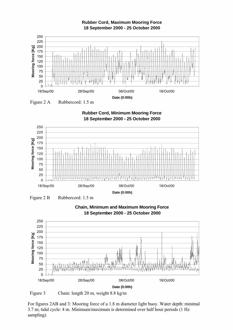
For figures 2AB and 3: Mooring force of a 1.8 m diameter light buoy. Water depth: minimal 3.7 m; tidal cycle: 4 m. Minimum/maximum is determined over half hour periods (1 Hz sampling).
Rubber Cord, Maximum Mooring Force18 September 2000 - 25 October 2000
0255075
100125150175200225250
18/Sep/00 28/Sep/00 08/Oct/00 18/Oct/00
Date (0:00h)
Mo
ori
ng
fo
rce
[Kg
]
Rubber Cord, Minimum Mooring Force18 September 2000 - 25 October 2000
0
25
50
75
100
125
150
175
200
225
250
18/Sep/00 28/Sep/00 08/Oct/00 18/Oct/00
Date (0:00h)
Mo
ori
ng
fo
rce
[Kg
]
Chain, Minimum and Maximum Mooring Force18 September 2000 - 25 October 2000
0
25
50
75
100
125
150
175
200
225
250
18/Sep/00 28/Sep/00 08/Oct/00 18/Oct/00
Date (0:00h)
Mo
ori
ng
fo
rce
[Kg
]
Figure 2 A Rubbercord: 1.5 m
Figure 2 B Rubbercord: 1.5 m
Figure 3 Chain: length 20 m, weight 8.8 kg/m
Two identical buoys (1.8 m diameter) are moored close to each other, (minimum water depth 3.7 m, maximum tidal cycle: 4m, maximum current: 2 kn). One buoy is moored using chain (length 20 m, weight: 8.8 kg/m), the other buoy is moored using rubber (length 1.5 m 45 Shore A, standard Datawell terminals). Both buoys had a load cell plus data logger in the mooring line. During one year, the forces in both systems were monitored: every second the force was measured, and the minimum and maximum value of each half hour was stored.
Some typical autumn results are shown in Figures 2ab and 3. The weather in the shown time span is a combination of mild autumn weather, and a severe storm. All curves show tidal oscillations. In the rubber cord mooring, the force increases with high tide due to extra elongation. In the chain mooring, the force increases since more chain is lifted from the seabed. One can see that the force of the rubber cord is typically much larger than the force of the chain mooring. As expected, the rubber cord is kept under tension, avoiding wear on the shackle, mooring eyes, and terminal connections. In the first halve of the figure, smooth oscillations in the chain mooring can be observed, whereas in the storm period some peaks loads are observed. These peaks however do not exceed the forces on the rubber cord. Handling
A typical weight reduction by a factor 10 or 20 compared to a chain mooring makes the handling of a rubber cord mooring system a delight on deck or in store. The rubber cord itself is solid, and made of natural rubber known for its excellent properties. Although life on the sea can be rough, no rubber cord has ever been damaged on a ship.
For safety reasons, Datawell’s policy has always been to have no force on the elastic part
of the mooring when retrieving a buoy. The Dutch lighthouse authorities have made the same decision. Handling procedures varying with circumstances have been developed. In the shallow water situation, two methods have been tested: 1) using a ground chain that is picked up by a drag, 2) with barbed hooks welded onto the terminals. The latter method, still under development, is only suited for single point mooring systems.
Often a kind of safety line is used to limit the elongation of the elastic mooring, and suggesting the retrieval of the mooring stone via the safety line. This has the obvious risk that the unknown state of the mooring gets the full load. Although serious accidents are only expected once in a lifetime, the risk should not be run. Future
In view of the excellent results of the shallow water situation with relatively small navigation buoys, larger navigation buoys on new locations will be moored with Datawell rubber cord moorings. The experience of thousands of Waverider moorings and hundreds of Wavec buoy moorings, in both near shore and open sea, and with breaking waves and large tidal currents, will be used to moor navigation buoys. Various designs with or without safety-line, with 45 or 60 shore rubber and varying diameter of rubber are considered to make the most successful mooring for navigation buoys.
Conclusion
A proven system for Waveriders has shown to be a reliable mooring for navigation buoys in shallow water as well. Inspection of moored buoy show indeed the expected reduced wear of the metal/metal connections. Since the length of the rubber mooring system is much shorter than the length of the chain mooring, the buoy stays closer to its anchoring. An expected advantage is the increase of the inspection intervals, resulting in a reduction of annual inspection costs. References [1] Datawell Internal report “Omvlechting”, See also ORETECH standard Product Catalogue
Oceanography and Geophysics, ENDECO fail-safe mooring accumulator type 996, page 387.
[2] ORETECH standard Product Catalogue Oceanography and Geophysics, ENDECO fail-safe mooring accumulator type 996, page 386.
[3] Proceeding of the Conference held at the National Institute of Oceanography 1972, Editor: L. Draper; IOS report NO 145 1982 “Operational Experience with Waverider buoys and their moorings”, by JD Humphery; Datawell Waverider manual, Datawell Wavec manual, Datawell Directional Waverider manual.