
2
Drilling DepartmentPresented By: Muhammad Noman Khan s/o
Muhammad Hanif Khan
3
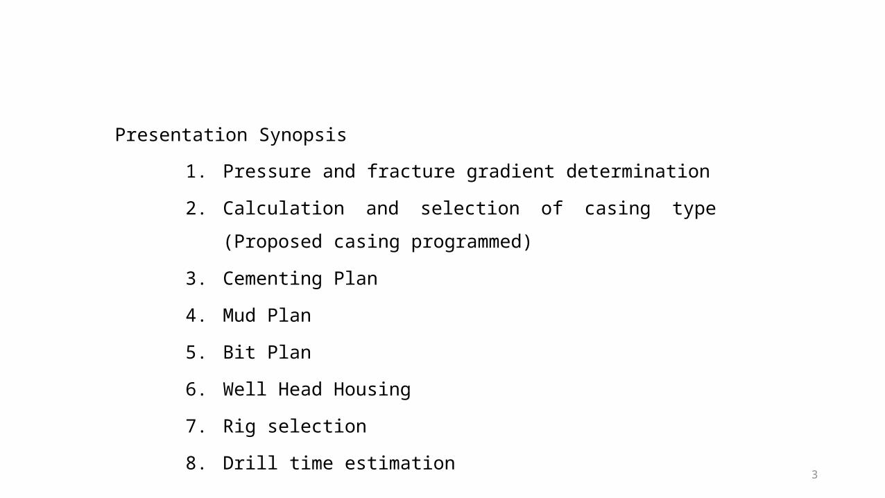
Presentation Synopsis
1. Pressure and fracture gradient determination
2. Calculation and selection of casing type (Proposed casing
programmed)
3. Cementing Plan
4. Mud Plan
5. Bit Plan
6. Well Head Housing
7. Rig selection
8. Drill time estimation
4
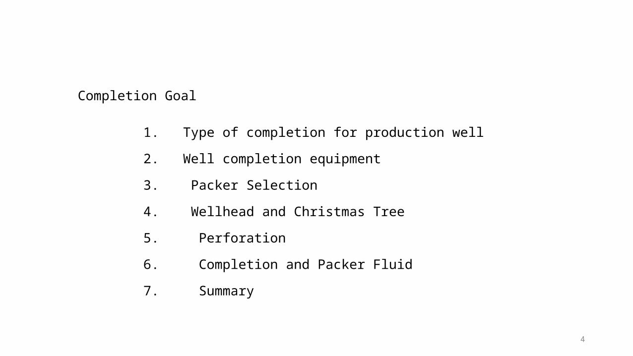
1. Type of completion for production well
2. Well completion equipment
3. Packer Selection
4. Wellhead and Christmas Tree
5. Perforation
6. Completion and Packer Fluid
7. Summary
Completion Goal
5
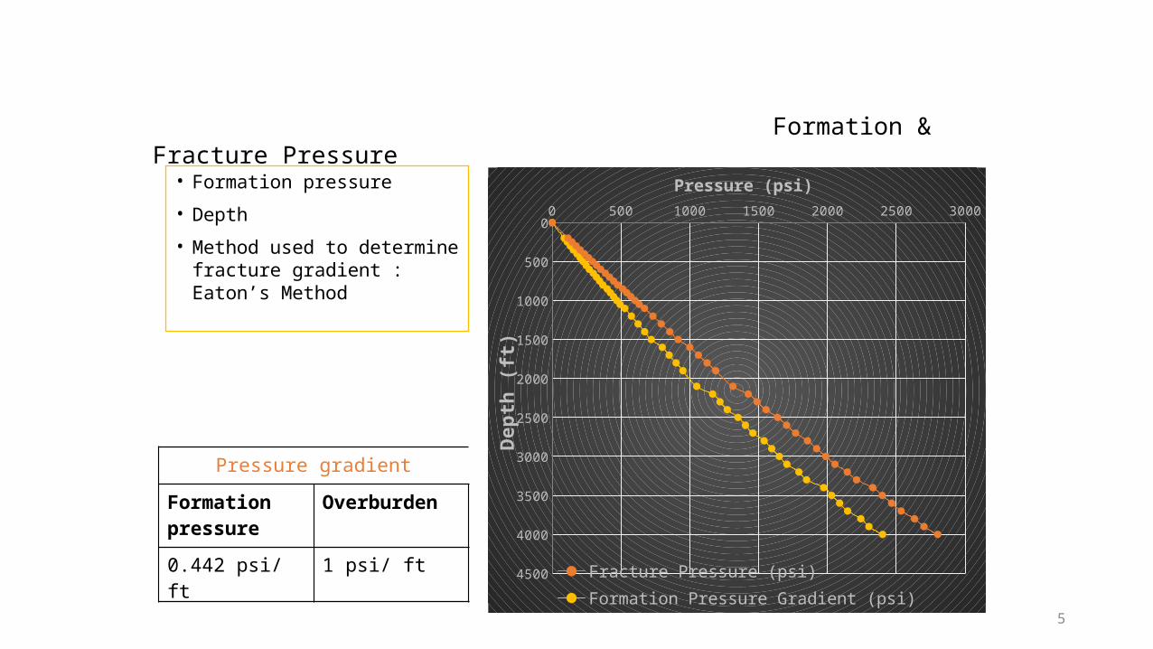
Formation & Fracture Pressure
0 500 1000 1500 2000 2500 30000
500
1000
1500
2000
2500
3000
3500
4000
4500 Fracture Pressure (psi)Formation Pressure Gradient (psi)
Pressure (psi)
Dept
h (ft
)
Pressure gradient
Formation pressure
Overburden
0.442 psi/ ft 1 psi/ ft
• Formation pressure• Depth• Method used to determine
fracture gradient : Eaton’s Method
6
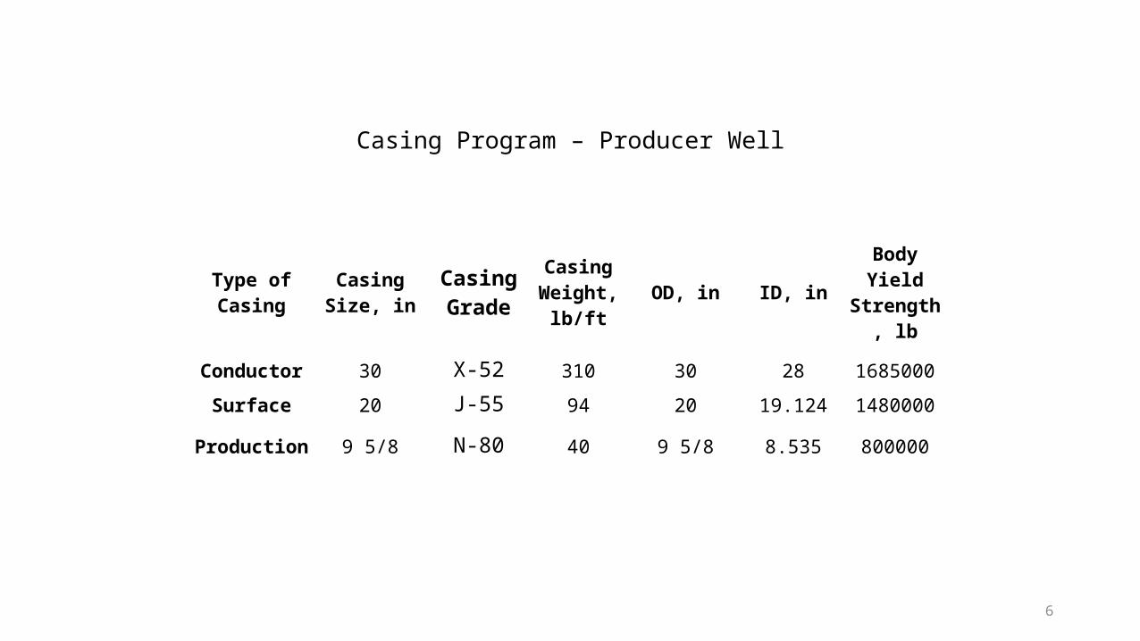
Type of Casing
Casing Size, in
Casing Grade
Casing Weight,
lb/ftOD, in ID, in Body Yield
Strength, lb
Conductor 30 X-52 310 30 28 1685000
Surface 20 J-55 94 20 19.124 1480000
Production 9 5/8 N-80 40 9 5/8 8.535 800000
Casing Program – Producer Well
7
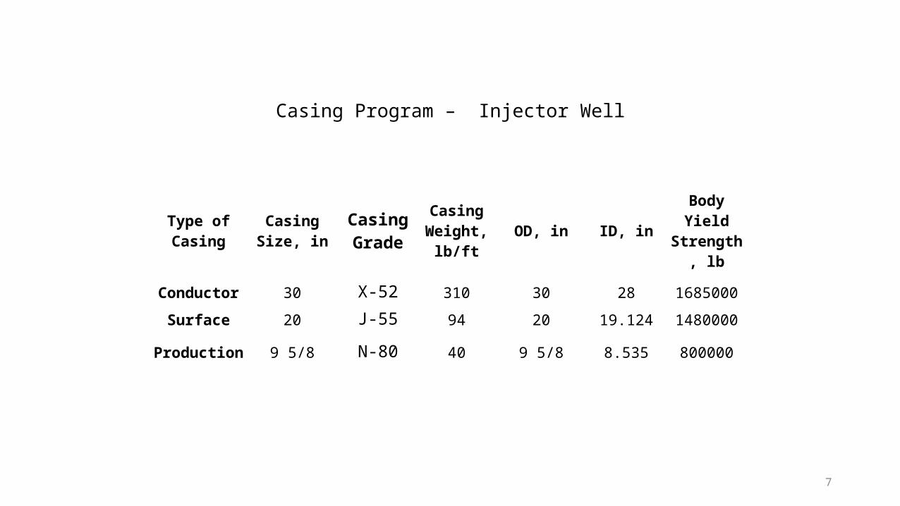
Type of Casing
Casing Size, in
Casing Grade
Casing Weight,
lb/ftOD, in ID, in Body Yield
Strength, lb
Conductor 30 X-52 310 30 28 1685000
Surface 20 J-55 94 20 19.124 1480000
Production 9 5/8 N-80 40 9 5/8 8.535 800000
Casing Program – Injector Well

8
Hole Size, in Casing Size
Mud Type Mud Weight,
ppg
Total Amount, bbl
36 30” Seawater, Sweep/Pad
mud
9.5 850
26 20” Seawater, Sweep/Pad
mud
10 1400
12 ½” 9 5/8” KCL Polymer Mud
12 665
Mud Plan
9
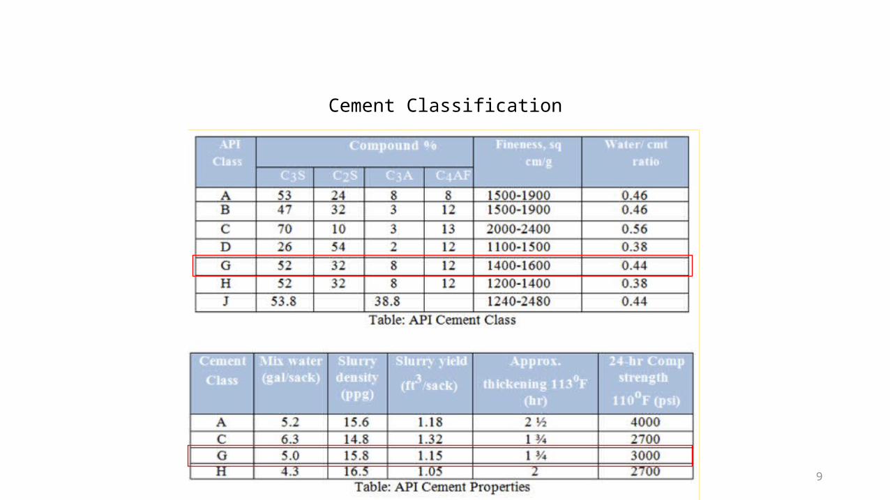
Cement Classification
10
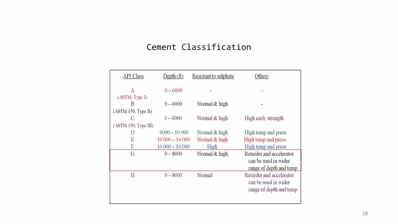
Cement Classification
11
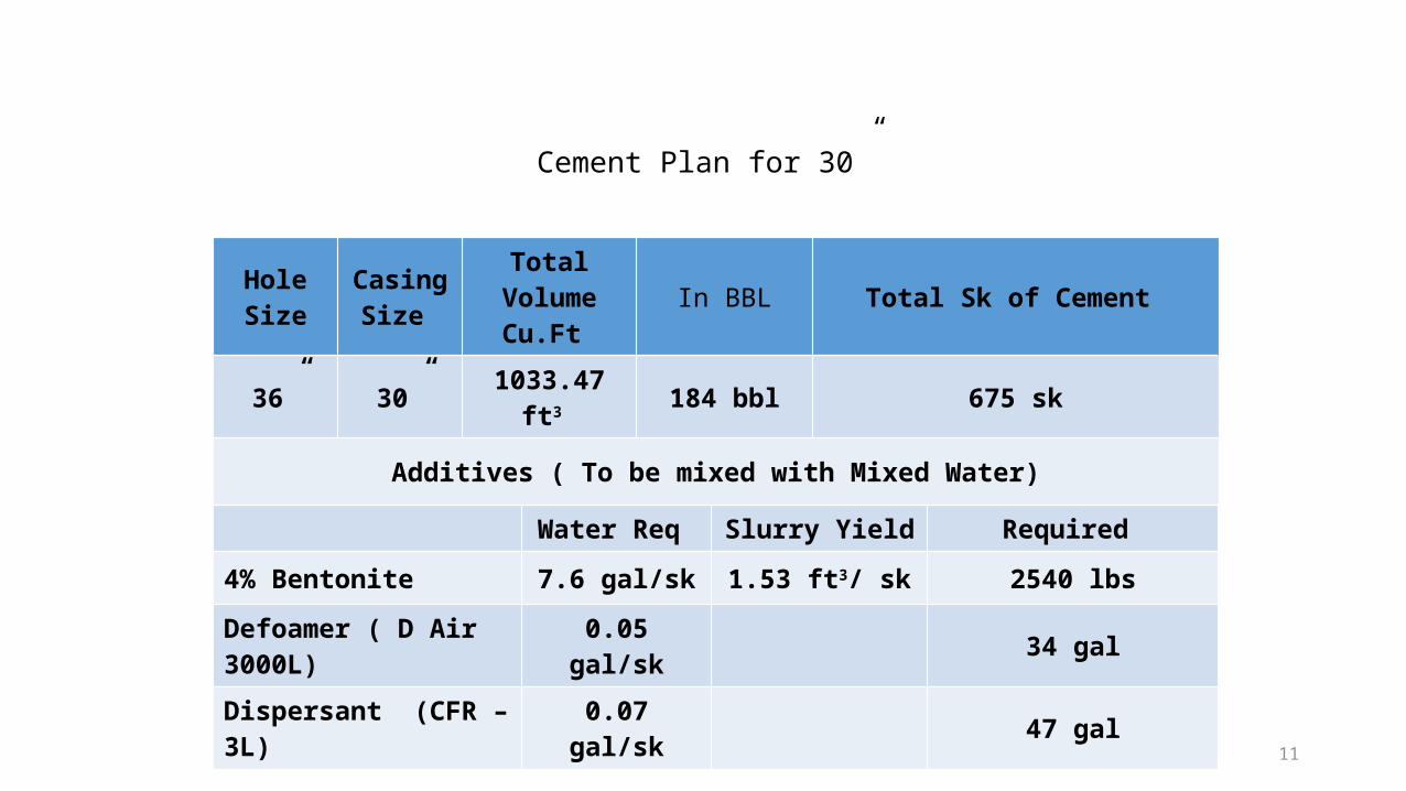
Hole Size
Casing Size
Total VolumeCu.Ft In BBL Total Sk of Cement
36” 30” 1033.47 ft3 184 bbl 675 sk
Additives ( To be mixed with Mixed Water)
Water Req Slurry Yield Required
4% Bentonite 7.6 gal/sk 1.53 ft3/ sk 2540 lbs
Defoamer ( D Air 3000L) 0.05 gal/sk 34 gal
Dispersant (CFR – 3L) 0.07 gal/sk 47 gal
Cement Plan for 30”
12
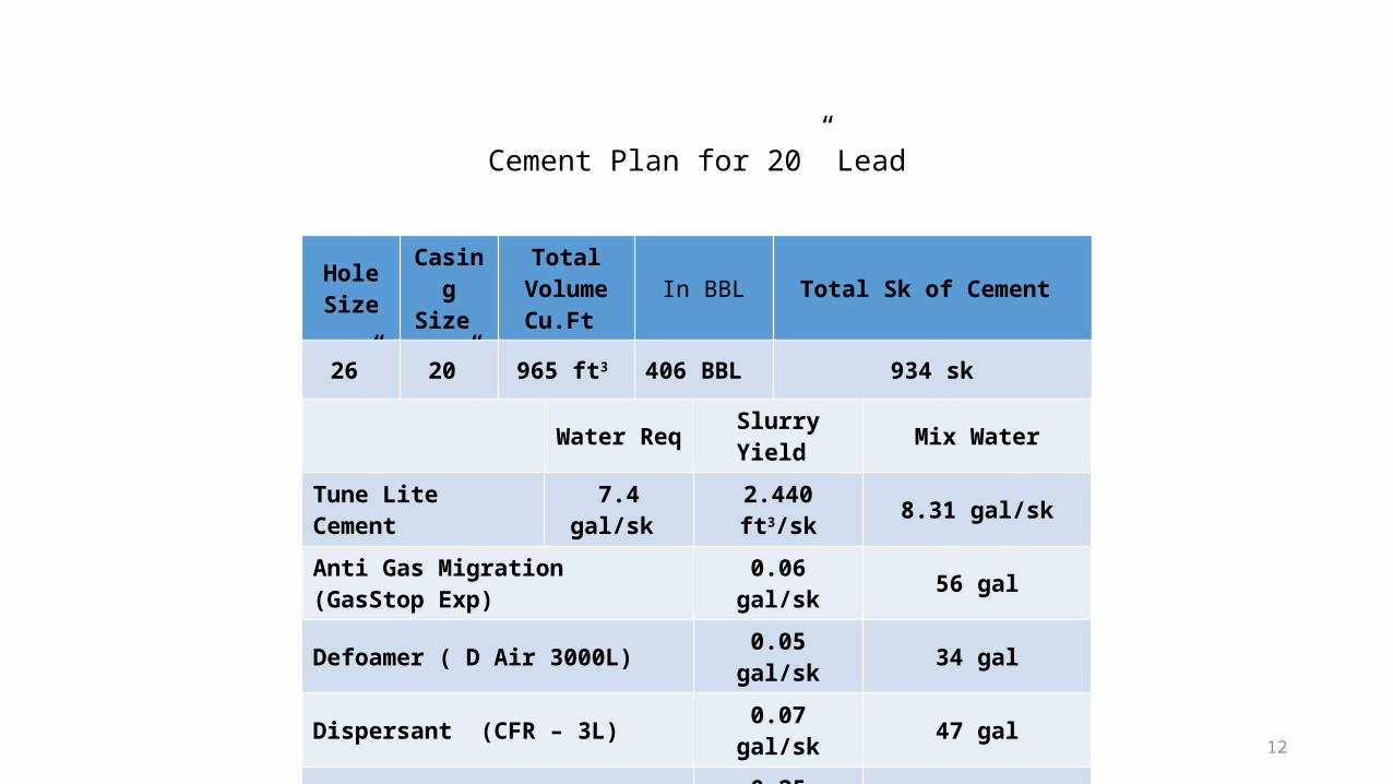
Hole Size
Casing Size
Total VolumeCu.Ft
In BBL Total Sk of Cement
26” 20” 965 ft3 406 BBL 934 sk
Water Req Slurry Yield Mix Water
Tune Lite Cement 7.4 gal/sk 2.440 ft3/sk 8.31 gal/sk
Anti Gas Migration (GasStop Exp) 0.06 gal/sk 56 gal
Defoamer ( D Air 3000L) 0.05 gal/sk 34 gal
Dispersant (CFR – 3L) 0.07 gal/sk 47 gal
Cement Retarder (SCR 500L) 0.25 gal/sk 235 gal
Fluid Loss Additive (Halad-413L) 0.20 gal/sk 185 gal
Cement Plan for 20” Lead
13
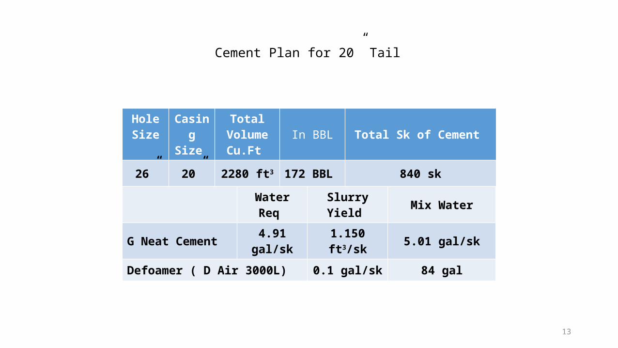
Hole Size Casing
Size
Total VolumeCu.Ft
In BBL Total Sk of Cement
26” 20” 2280 ft3 172 BBL 840 sk
Water Req Slurry Yield Mix Water
G Neat Cement 4.91 gal/sk 1.150 ft3/sk 5.01 gal/sk
Defoamer ( D Air 3000L) 0.1 gal/sk 84 gal
Cement Plan for 20” Tail
14
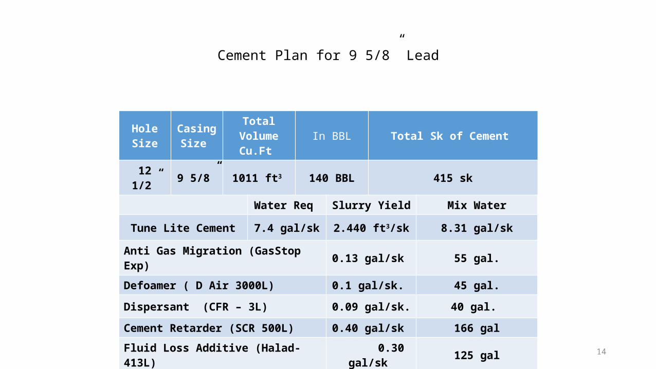
Hole Size
Casing Size
Total VolumeCu.Ft In BBL Total Sk of Cement
12 1/2” 9 5/8” 1011 ft3 140 BBL 415 sk
Water Req Slurry Yield Mix Water
Tune Lite Cement 7.4 gal/sk 2.440 ft3/sk 8.31 gal/sk
Anti Gas Migration (GasStop Exp) 0.13 gal/sk 55 gal.
Defoamer ( D Air 3000L) 0.1 gal/sk. 45 gal.
Dispersant (CFR – 3L) 0.09 gal/sk. 40 gal.
Cement Retarder (SCR 500L) 0.40 gal/sk 166 gal
Fluid Loss Additive (Halad-413L) 0.30 gal/sk 125 gal
Cement Plan for 9 5/8” Lead
15
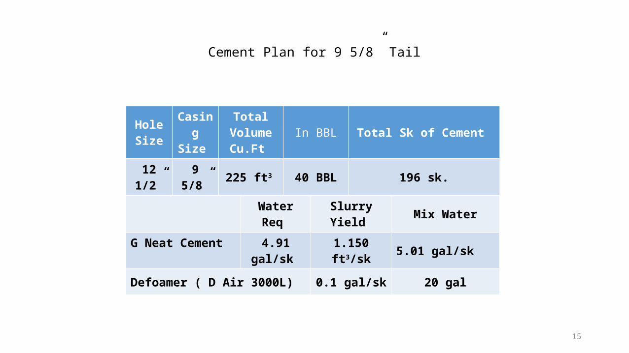
Hole Size
Casing Size
Total VolumeCu.Ft
In BBL Total Sk of Cement
12 1/2” 9 5/8” 225 ft3 40 BBL 196 sk.
Water Req Slurry Yield Mix Water
G Neat Cement 4.91 gal/sk 1.150 ft3/sk 5.01 gal/sk
Defoamer ( D Air 3000L) 0.1 gal/sk 20 gal
Cement Plan for 9 5/8” Tail
16
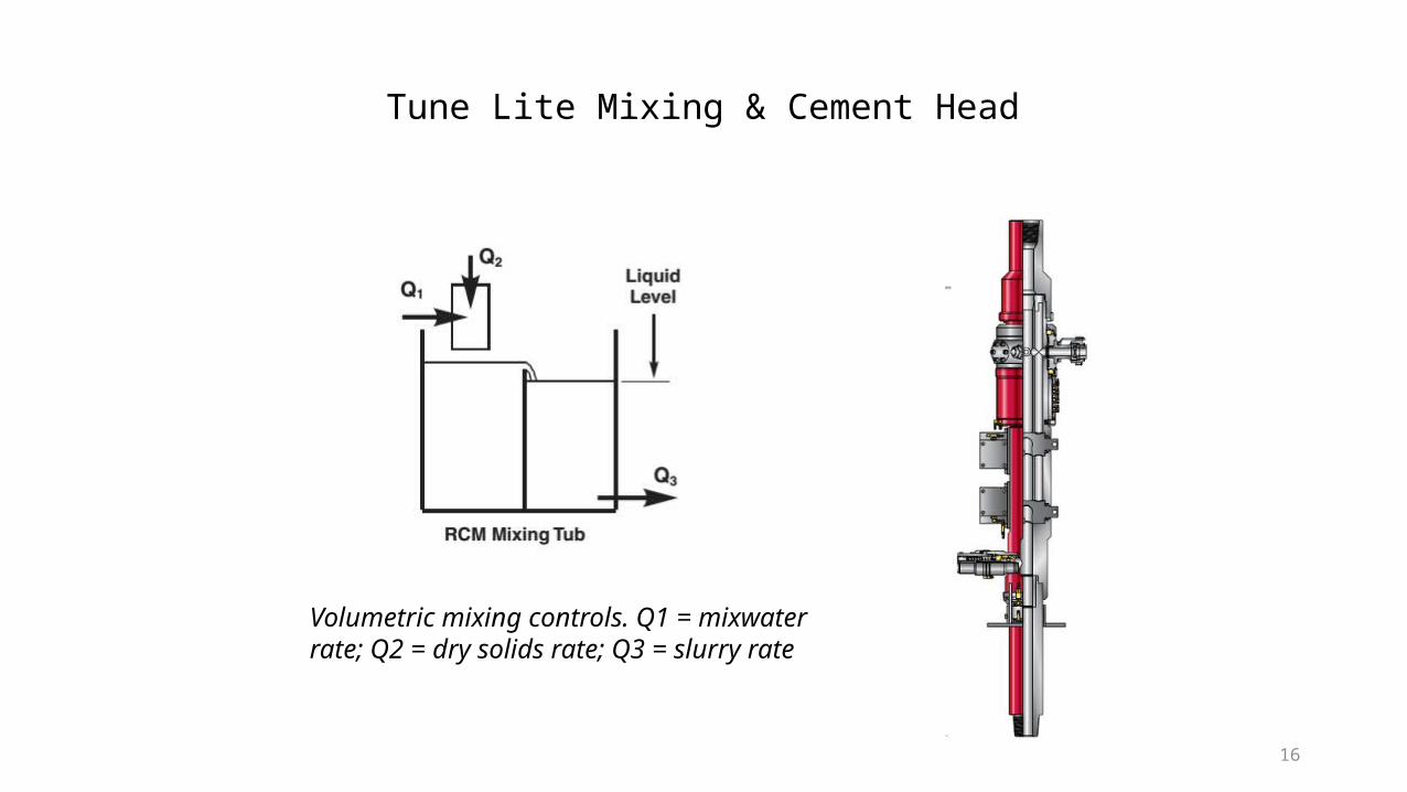
Volumetric mixing controls. Q1 = mixwater rate; Q2 = dry solids rate; Q3 = slurry rate
Tune Lite Mixing & Cement Head
17
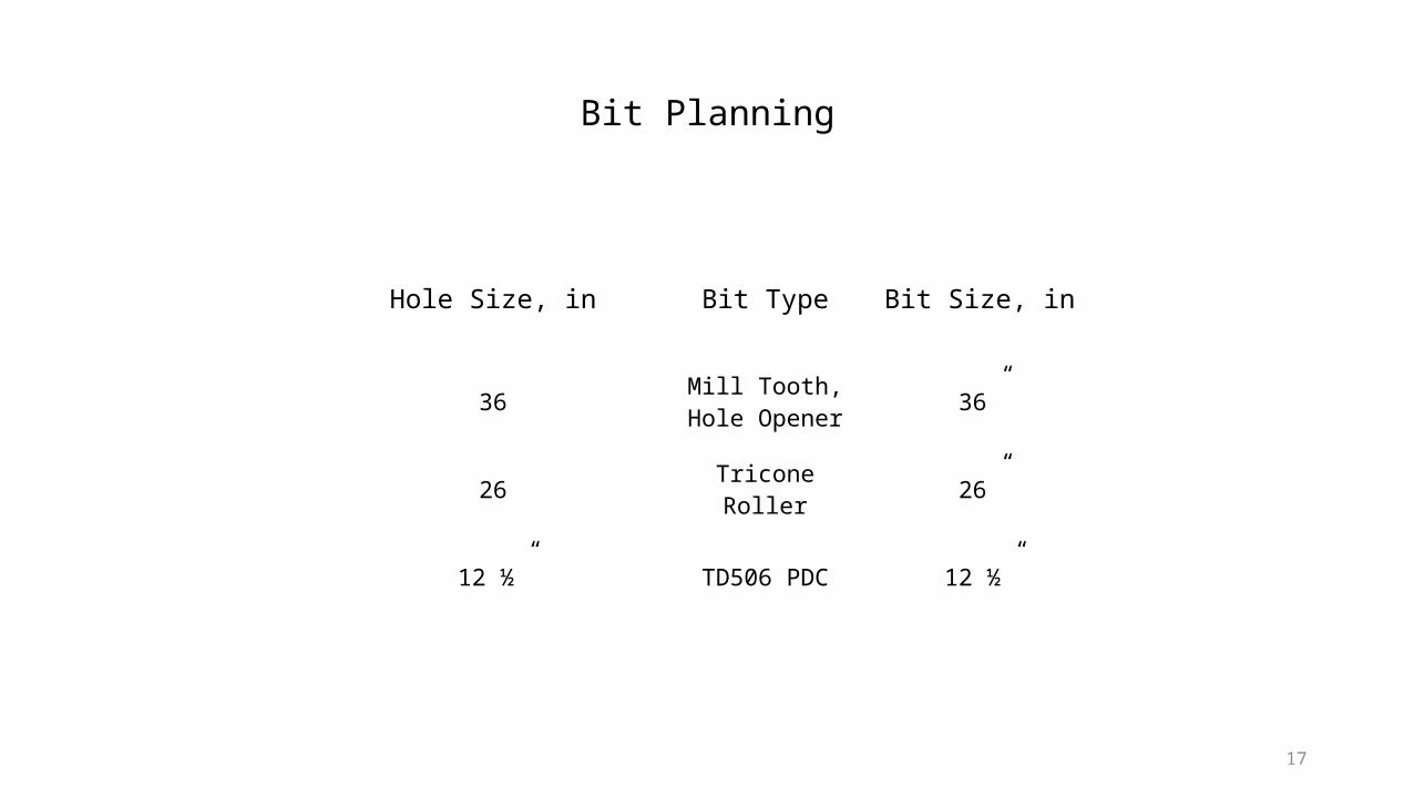
Hole Size, in Bit Type Bit Size, in
36 Mill Tooth, Hole Opener 36”
26 Tricone Roller 26”
12 ½” TD506 PDC 12 ½”
Bit Planning
18
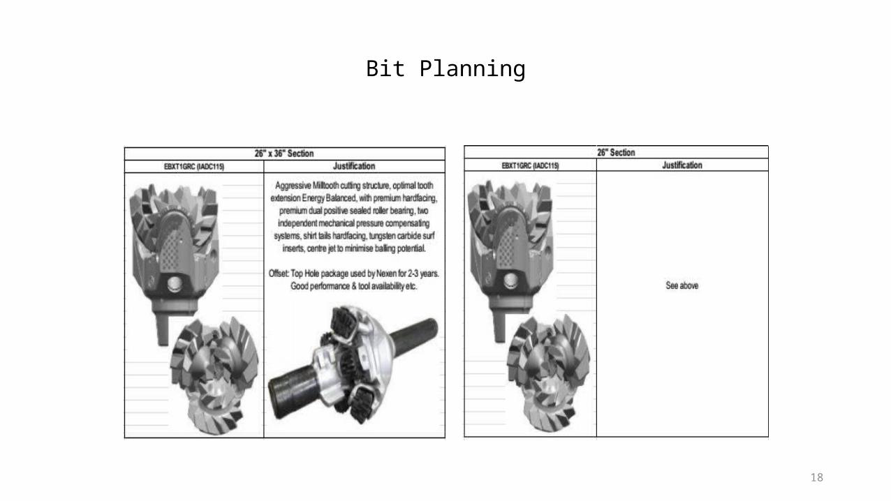
Bit Planning
19
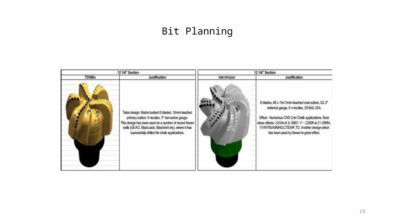
Bit Planning
20
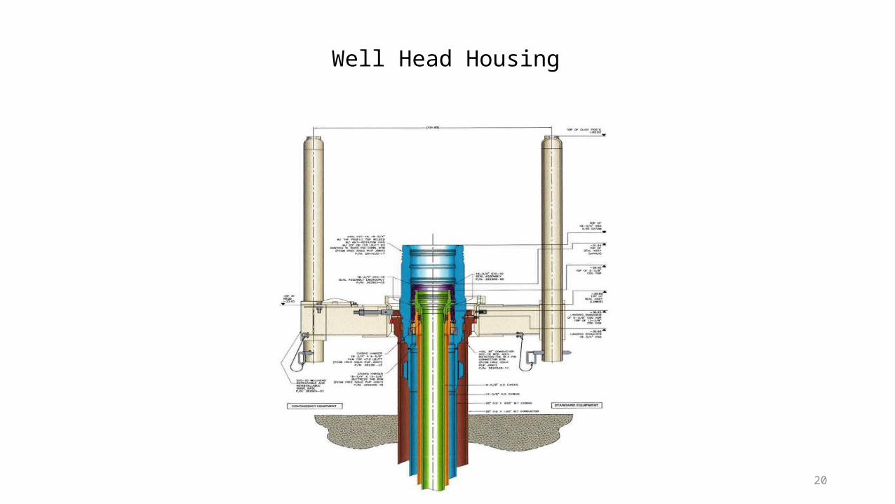
Well Head Housing
21
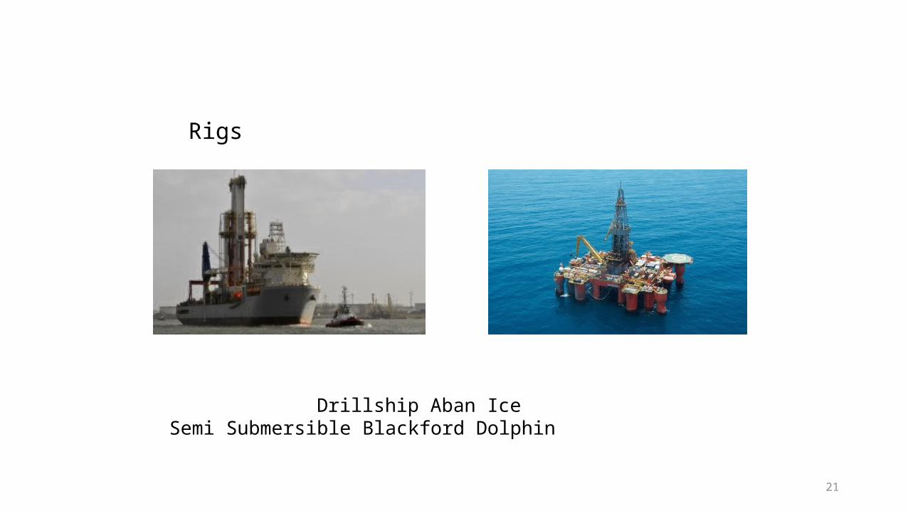
Drillship Aban Ice Semi Submersible Blackford Dolphin
Rigs
22
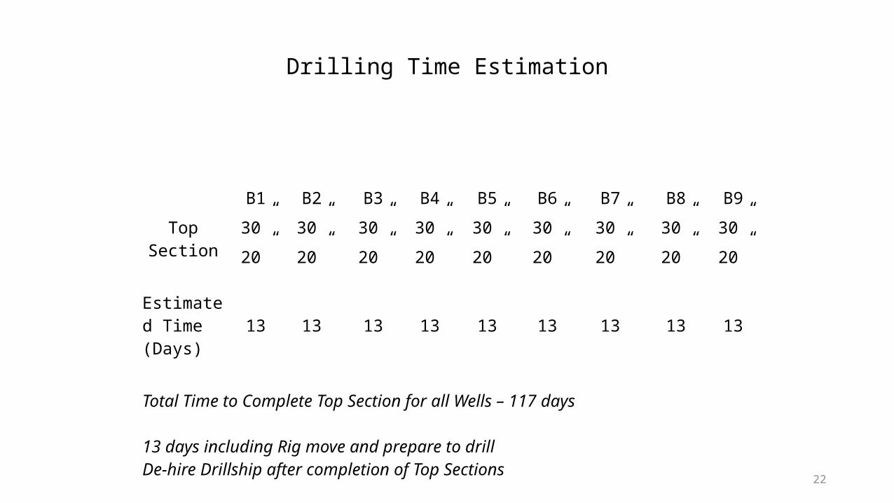
B1 B2 B3 B4 B5 B6 B7 B8 B9
Top Section 30” 30” 30” 30” 30” 30” 30” 30” 30”
20” 20” 20” 20” 20” 20” 20” 20” 20”
Estimated Time (Days)
13 13 13 13 13 13 13 13 13
Total Time to Complete Top Section for all Wells – 117 days
13 days including Rig move and prepare to drillDe-hire Drillship after completion of Top Sections
Drilling Time Estimation
23
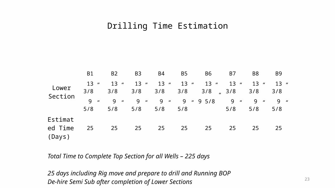
B1 B2 B3 B4 B5 B6 B7 B8 B9
Lower Section
13 3/8” 13 3/8” 13 3/8” 13 3/8” 13 3/8” 13 3/8” 13 3/8” 13 3/8” 13 3/8”
9 5/8” 9 5/8” 9 5/8” 9 5/8” 9 5/8” 9 5/8” 9 5/8” 9 5/8” 9 5/8”
Estimated Time (Days)
25 25 25 25 25 25 25 25 25
Total Time to Complete Top Section for all Wells – 225 days
25 days including Rig move and prepare to drill and Running BOPDe-hire Semi Sub after completion of Lower Sections
Drilling Time Estimation
24
• Pipe Sticking• Differential-Pressure Pipe Sticking• Mechanical Pipe Sticking
• Loss of Circulation• Drillpipe Failures
• Twistoff• Fatigue• Pipe-Failure Prevention
• Hydrogen-Sulfide-Bearing Zones and Shallow Gas• Since we don’t have log data, we very much depend on the real time
drilling operations, Hence we have to be very careful about gas kick or loss.
Drilling Challenge
25
• Fire-fighting equipment must be available for emergency use in the event of a fire
and should be provided in first-class working order.
• Unauthorized person should not be allowed to be on the rig at any time.
• Personnel who not involved directly in the particular operation should keep away
from operation site.
• Sea survival and offshore course is compulsory for all personnel.
Safety