Post-weld residual stresses and heattreatments of Gas Tungsten Arc Weldedaluminum alloy AA6061-T651
by
M. W. Dewan, J. Liang, M. A. Wahab and A. M. Okeil
reprinted from
WORLD JOURNALOF ENGINEERING
VOLUME 10 NUMBER 1 2013
MULTI-SCIENCE PUBLISHING COMPANY LTD.
World Journal of
EngineeringWorld Journal of Engineering 10(1) (2013) 11-22
1. IntroductionAA-6061 T651 Aluminum Alloy is a heat-
treatable alloy, has high strength and corrosionresistance properties. It is used in various structuraland aerospace applications. Magnesium and siliconare added either in balanced amounts to form quasi-
Post-weld residual stresses and heattreatments of Gas Tungsten Arc Welded
aluminum alloy AA6061-T651
M. W. Dewan1, J. Liang1, M. A. Wahab1,* and A. M. Okeil21Department of Mechanical Engineering, 2508 Patrick F. Taylor Hall, Louisiana State
University, Baton Rouge, Louisiana 70803, USA2Department of Civil & Environmental Engineering, Louisiana State University, 3418
Patrick F. Taylor Hall, Baton Rouge, Louisiana 70803, USA*E-mail: [email protected]
(Received 18 February 2012; accepted 22 October 2012)Abstract
Heat-treatable AA-6061-T651 Aluminum alloys (Al-Mg-Si) have found considerableimportance in structural and aerospace applications for their high strength to weight ratio andimproved corrosion resistance properties. Intrinsic weld defects, post-weld residual stresses, andmicrostructural changes are the key factors for performance reductions and failures of weldedstructures. Gas-Tungsten-Arc-Welding (TIG/GTAW) was carried out on AA-6061-T651 plateswith Argon/Helium (50/50) as the shielding gases. Non-destructive Phased-Array-Ultrasonic-Testing (PAUT) was applied for the detection and characterization of weld defects andmechanical performances. Ultrasonic technique was used for the evaluation of post-weld residualstresses in welded components. The approach is based on the acoustoelastic effect, in whichultrasonic wave propagation speed corresponds to the magnitude of stresses present within thematerials. To verify the PAUT’s residual stress results, a semi-destructive hole-drilling techniquewas used; and observed analogous results. The effects of post-weld-heat-treatment (PWHT) onthe residual stresses, grain size, micro-hardness, and tensile properties are also studied. The grainsize and micro-hardness values are studied through Heyn’s method and Vickers hardness test,respectively. Lower residual stresses are observed in post-weld heat-treated specimens, which arealso confirmed from microstructural and micro-hardness studies. The PWHT enhanced tensileproperties for the redistribution of microstructures and residual stresses.
Key words: Post-weld residual stresses, TIG/GTAW, Post-weld heat treatment, Phasedarray ultrasonic testing (PAUT), Microstructural evolutions
World Journal of
Engineering
binary Al-Mg2Si or with an excess of silicon, which isneeded to form Mg2Si precipitate (Lakshminarayananet al., 2009). Al-Mg-Si alloys find wide applicationsfor its weldability advantages over other high strengthaluminum alloys (Dudas and Collins, 1966; Metzger,1967). It is widely used in the aerospace industry, and
ISSN:1708-5284
12 M. W. Dewan et al./World Journal of Engineering 10(1) (2013) 11-22
has gathered wide acceptance in the fabrication oflightweight structures. The increased use ofaluminum alloy calls for more efficient and reliablewelding processes which has always represented agreat challenge for designers and technologists. Foraluminum alloy, generally Friction-Stir Welding(FSW) and fusion welding are used to make awelded-joint. Two of the most common fusionwelding practices are Gas Tungsten Arc welding(GTAW) (also known as Tungsten Inert Gas (TIG))and Metal Inert Gas (MIG) welding. GTAW weldingis a high quality weld that uses a non-consumableelectrode and smaller current compared to MIGwelding. (Kumar and Sundarrajan, 2006) studied theeffects of welding parameters on the mechanicalproperties of the as-welded condition for aluminumalloy AA6061-T6. High coefficient of thermalexpansion of aluminum, solidification shrinkage, andhigh solubility of hydrogen during its molten statecreates problem during fusion welding of aluminumalloys (Lakshminarayanan et al., 2009). All of thesefactors can cause variable degrees of decrease instrength along the weld and its surrounding area.
During the welding process the exposure to hightemperature followed by rapid cooling near the weldcauses the grains to coarsen in the heat-affected-zone (HAZ) and induce post-weld residual stressesalong the weld line and in the HAZ (Leggatt, 2008).The materials in the HAZ effectively becomes softerand more susceptible to failure (Malin, 1995). Thematerial on the surface or nearest to the weld is thelast to cool down; and the rest of the material causesthis portion of the weld plate to form a tensileresidual stress. In some materials, the maximumtensile residual stress may reach up to the yieldstrength of the material. The restraint used duringwelding may cause welded joint to expand andcontract and has an effect on the development of thevarious residual stresses in each direction;transversely, longitudinally, and in the directionnormal to the plane of welding. Different factorsplay a role in the magnitude of stresses thataccumulate along the weld. The geometry of theweld, the weld-pass sequence (single or multi-passwelds), or the use of fabrication aids, such as jigsand fixtures, tacks, or cleats may have the directeffect on the development of residual stresses on thewelded joint. During the in-service operation ofwelded parts tensile residual stresses can causeharmful damages. Therefore, measuring of the levelof residual stresses in a welded structure has a great
importance. Over the last few decades variousresidual stress measurement techniques have beendeveloped. In general, these techniques are qualifiedas destructive and non-destructive techniques. Mostcommon destructive techniques are the hole-drillingmethod, the ring core technique, the bendingdeflection method, and the sectioning method(Ajovalasit et al., 1996; Rossini et al., 2012). Thesemethods are widely used in industry and they aresensitive to the macroscopic residual stress levels.Non-destructive methods are developed on the basisof the relationship between residual stress and thephysical or crystallographic parameters. Differentnon-destructive techniques are developed such asthe X-ray diffraction method, the neutron diffractionmethod, the ultrasonic method, and the magneticmethod. X-ray diffraction method is used formeasurement of surface and very limited subsurfacestresses and that’s why it may be considered asurface method. On the other hand, neutrondiffraction method allows measurement up to thedepth of 50 mm. X-ray and neutron diffractionmethods are expensive and cannot be carried out in-situ (Rossini et al., 2012). Non-destructiveultrasonic testing can be used in most materials tomeasure residual stresses. Variations in the velocityof the ultrasonic waves can be related to the residualstress state (Sanderson and Shen, 2010). Ultrasonicwaves and acoustoelasticity allows measurement ofsurface and subsurface residual stresses. Surface andsubsurface stresses can be determined by usingshear waves or longitudinal waves. Many attemptshave been proposed for this purpose. Recent studiesare mostly focused on critically refractedlongitudinal (LCR) wave method (Clark andMoulder, 1985; Bray, 2001; Uzun and Bilge, 2011).This technique allows measurement of in-planestresses. Surface stresses, as well as bulk stressescan be determined by using ultrasonic longitudinalwaves. Longitudinal waves polarize in the samedirection that it propagates. Anisotropy in thematerial caused by stress, affect the propagationvelocity of longitudinal waves. Stresses normal tothe wave propagation direction can be measuredusing the longitudinal waves.
During the welding process, microstructures ofthe material change and this causes the variations ofwave velocities within the Heat-Affected-Zone(HAZ) areas. Effect of stress on wave propagationwas investigated by (Hughes and Kelly, 1953) in their study entitled “Second-Order Elastic
M. W. Dewan et al./World Journal of Engineering 10(1) (2013) 11-22 13
Deformation of Solids.” They have determined thevelocities of longitudinal and shear waves as afunction of applied stress by subjecting the materialto hydrostatic pressure, which is defined ascompression on the material. The expressionrelating to the velocity of a wave propagating in thelongitudinal direction to an internal stressed fieldcan be written as:
(1)
Where, υ0 in the wave speeds in an unstressedmedium; υ is the velocity of an ultrasonic wavepropagating in an stressed medium; σ 1, σ 2, and σ 3
are the principal stresses, and K1, K2 are theacoustoelastic constants. If the measurement ismade in a single propagating direction (for instancedirection-1), the above equation can be simplifiedand expressed as follows:
(2)
For the majority of materials studied,acoustoelastic constant K1�K2 (Thompson, 1996),therefore the above equation (2) can be reduced andthe residual stress component can be calculated byfollowing relationship:
(3)
The acoustoelastic constant K1 relates to theultrasonic velocity to the stress, and can be obtainedexperimentally. Acoustoelastic constant isdetermined as the relation between the total residualstresses normal to the wave propagation and theultrasonic wave velocity variation. This constant iscalculated by observing wave velocity variationsdue to applied stress. From the slope of the wavevelocity change vs. stress, acoustoelastic constant isdetermined. In this study we have usedacoustoelastic constant K1 = 5.04 × 10⁻⁶ (MPa)−1.Ultrasonic longitudinal waves are propagatedthrough the thickness of the material and wavetransit time is measured. Pulse-echo technique andthrough transition technique are able to measurewave transit time. From the time measurement,sound velocity can be measured by knowing the
συ υ
υ10
1 0=
−
×K
υ υυ
σ σ−
= +0
01 1 2 2K K
υ υυ
σ σ σ−
= + +0
01 1 2 2 3K K ( )
thickness. As a result of these measurements,average residual stress through the thickness of thematerial can be estimated.
Post-weld-heat-treatment (PWHT) is an optionto recover strength in the HAZ of heat-treatablealloys, which was originally lost due to weldthermal cycle. For AA-6061, ageing, or precipitatehardening, is one form of pos-weld-heat-treatment(PWHT). During the ageing process material is keptto a specified temperature for an extended period oftime, depending on the type of material being used,and the types of precipitates. Exposing the materialto a temperature for longer than required forartificial age hardening can cause the precipitates togrow too large and more widely dispersed in thematerial (Tan and Said, 2009). These growth anddispersion effects cause the material to becomesofter, and lose its strength. So, optimum ageingtemperature and time required are necessary toobtain better strength. Closely packed atoms of thesolute form required in the solution first. Theseatoms then form Guinier-Preston (GP) zones,which are connected with the solvent matrix (Gaoet al., 2002). Recent studies on the effect ofPWHT on AA-2219 joints showed significantimprovement in the mechanical properties of theweldments (Liu et al., 2006). Mechanical propertiesof TIG welded AA-8090 alloys were enhanced byPWHT due to grain refinement (Ravindra andDwarakadasa,1992). Uniformly distributed Mg2Siprecipitates, smaller grain size, and higherdislocation density have all been shown to be thereasons for enhanced mechanical properties due toPWHT of FSW AA-6061 alloys (Elangovan andBalasubramanian, 2008). In the literature, it isshown that the slight improvement in yieldstrength, tensile strength, and hardness of thewelded joints can be achieved by solution treatmentfollowed by artificially aging (Metzger, 1967;Periasamy, et al., 1995).
The general lack of data on residual stresses andPWHT on the mechanical performances of GTA-welded AA-6061-T651 alloys with AA-4043 fillermetal has prompted this present experimentalstudy. This research aimed at conducting asystematic study to determine weld defects andresidual stresses by using nondestructiveultrasonic testing. The effect of PWHT on theresidual stresses, tensile properties, and microhardness were also investigated. The fracturemorphology was studied by using scanning
14 M. W. Dewan et al./World Journal of Engineering 10(1) (2013) 11-22
electron microscopy (SEM) micrographs. Toobserve the effect of PWHT on grain size, opticalmicrographs were analyzed for grain sizedetermination by Heyn’s method.
2. Materials and experimental procedures2.1. Materials and welding process
Rolled plates of AA-6061 T651 with 6.35 mmthickness were GTA welded according to AWSwelding codes for aluminum (AWS Welding Code,2008). The welding and testing procedures areshown in Table 1. The initial joint configurationwas obtained by securing the plates in positionusing precision guided rails and tack welding. Thewelding direction was normal to the plate’s rollingdirection and necessary care was taken to avoidjoint distortion by clamping the plates at suitable
positions. Multi-pass weld was used on both sidesto fabricate the butt joints. A gas mixture ofArgon/Helium (50/50) was used as shielding gas asthis mixture helps in the constriction of the arc andconcentrates the heat within a restricted area,thereby reducing the size of the heat-affected-zone(HAZ) (Howse and Lucas, 2000). Welding wasfollowed by natural ageing at room temperature for48 hours.
2.2. Experimental processAll the welds were visually and ultrasonically
inspected for defects. After scanning by phasedarray ultrasonic testing, the specimens were cutfrom defect-free regions according to ASTMstandard for tensile testing (ASTM, 2004). To studythe influence of post-weld-heat-treatment (PWHT)on residual stresses and mechanical properties, the
Table 1.Experimental procedures
Welding Process Gas Tungsten Arc Welding (GTAW)
Materials AA6061-T651 aluminum plate, 6.5 mm thickness (ALCOA MILL PRODUCTS, INC.)
Standard AWS Welding Code D1.2/D1.2 M standard, 2008Weld Type Double V, groove angle 45°, root opening 3.5 mm, and root face 3.5 mmElectrode Type tungsten electrode, diameter 2.38 mmShielding gas Argon/Helium (50/50)Filler rods diameter AA-4043 (AlSi5), 1.6 mm (American Welding Products, Inc.)Weld current 115–120 ampsWelding speed 120–140 mm/minUniaxial tensile test MTS 810 Servo-hydraulic universal testing machineStandard ASTM E8M-04 standardTest speed 0.05 mm/secHardness test Vickers micro-hardness tester (SunTech FM-1e)Load 100 gf, Indentation period: 15 secondsMicrostructural analysis Scanning electron microscope (SEM) and optical microscope (OM)Etchant Keller reagent (1% hydrofluoric acid, 1.5% hydrochloric acid,
2.5% nitric acid and 95% DI water)Residual stress measurement Standard: ASTM E837-0 standard Hole-drilling methodData acquisition unit InstruNet100 (Omega)Strain gage Strain gage rosette (3- element strain gages)Specific directions 0°, 45° and 135°Drilling speed 4000 rpmResidual stress measurement Ultrasonic testingUltrasonic pulser/receiver Panametrics (model: 5900PR, Frequency range: 1 kHz–200 MHz)Transducers Panametrics longitudinal wave fingertip size Transducers
(model V112, maximum frequency: 10 MHz)PCI digitizer board Acqiris PCI digitizer (maximum Sampling rate: 420 MS/s)Couplant Sonotech Inc.’s Ultragel II couplantWeld flaw detection Phased- Array Ultrasonic Testing (PAUT)Equipments OmniScan MX2, 16 elements phased array probes,
wedges, and a manual encoder (Olympus)
M. W. Dewan et al./World Journal of Engineering 10(1) (2013) 11-22 15
welded joints were subjected to different heattreatment processes. For “solution treatment (ST)”welded specimens were heated at 530°C for 1 hfollowed by quenching in water, and maintained atroom temperature. For “solution treated and agehardening (STAH)” specimens were heated at530°C for 1 h and then quenched in water,maintained at room temperature, followed by agingat 160°C for 18 h. For “age hardening (AH)” as-welded specimens were artificially aged at 160°Cfor 2 hours to 24 hours. In a previous study, (Kardakand Wahab, 2011) showed that the artificial agehardening at 160°C for 18 hours offer optimumtensile and micro hardness properties of GTA-welded AA6061-T651 aluminum alloy. In thisstudy, we have used artificial age hardening toobtain PWHT specimens. As-welded (AW)specimens were age-hardened into a conventionaloven at 160°C for 18-hours, followed by cooling atroom-temperature. For comparisons we have testedas welded specimens without age-hardening andPWHT with age-hardening.
Tensile tests were carried out at roomtemperature using an MTS-Universal TestingMachine. For comparisons we have tested basematerials, weld material with transverse centerweld, weld materials in parallel to weld direction,and HAZ materials. The tensile properties (0.2%proof strength), ultimate tensile strength, and %ageelongation were evaluated using at least 10 samplesin each condition prepared from the same weld joint.All samples were mechanically polished andultrasonically tested before tests to eliminate theeffect of any discontinuities present. The hardnessacross the weld cross section was measured usingVickers Micro-hardness testing machine. Thehardness was measured at the center of the crosssection as shown in Figure 1.
After the hardness testing, the samples weremetallographically polished according to ASTMstandard and etched with Keller’s reagent to
expose the grain boundaries. Optical micrographswere taken using light optical microscope (NikonMM-11) equipped with image analyzing software(SPOT Software version 4.7) to analyze thevariation of grain size due to heat treatment (HT).SEM and EDAX analysis was conducted usingHitachi S-3,600N system.
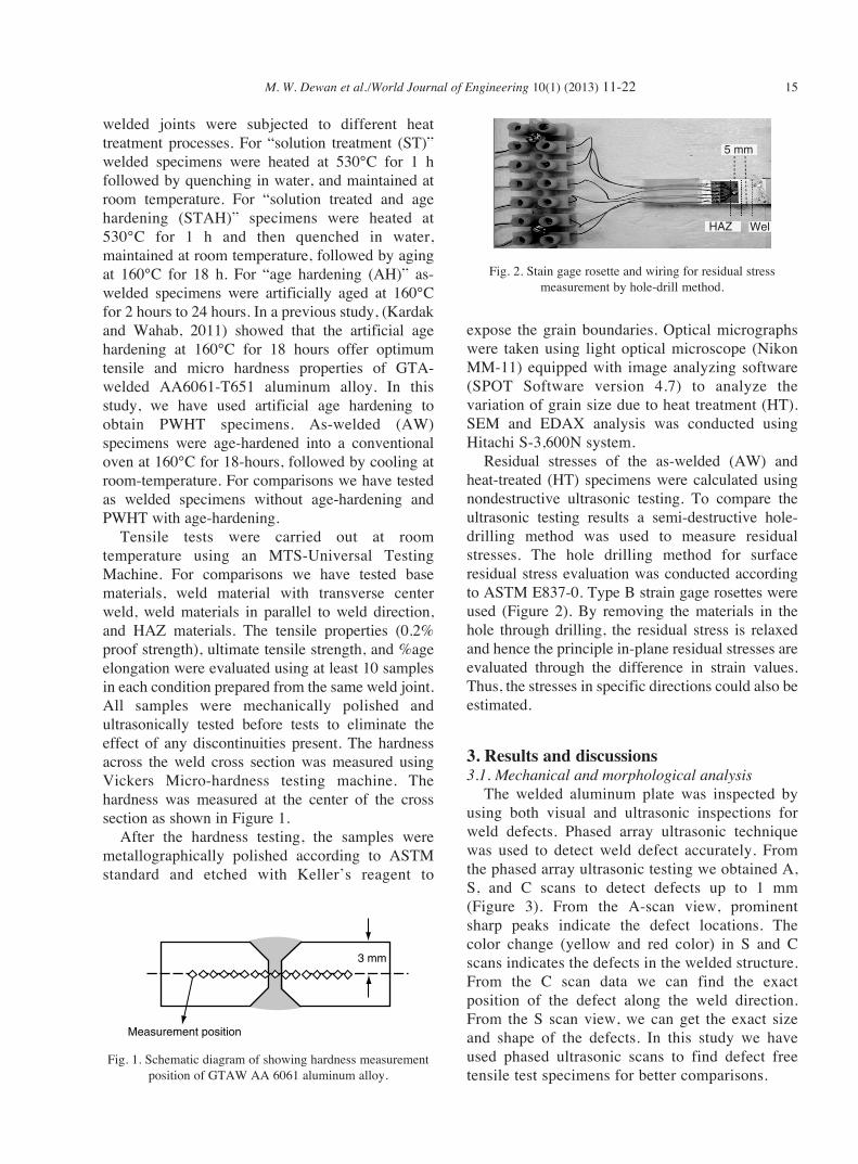
Residual stresses of the as-welded (AW) andheat-treated (HT) specimens were calculated usingnondestructive ultrasonic testing. To compare theultrasonic testing results a semi-destructive hole-drilling method was used to measure residualstresses. The hole drilling method for surfaceresidual stress evaluation was conducted accordingto ASTM E837-0. Type B strain gage rosettes wereused (Figure 2). By removing the materials in thehole through drilling, the residual stress is relaxedand hence the principle in-plane residual stresses areevaluated through the difference in strain values.Thus, the stresses in specific directions could also beestimated.
3. Results and discussions3.1. Mechanical and morphological analysis
The welded aluminum plate was inspected byusing both visual and ultrasonic inspections forweld defects. Phased array ultrasonic techniquewas used to detect weld defect accurately. Fromthe phased array ultrasonic testing we obtained A,S, and C scans to detect defects up to 1 mm(Figure 3). From the A-scan view, prominentsharp peaks indicate the defect locations. Thecolor change (yellow and red color) in S and Cscans indicates the defects in the welded structure.From the C scan data we can find the exactposition of the defect along the weld direction.From the S scan view, we can get the exact sizeand shape of the defects. In this study we haveused phased ultrasonic scans to find defect freetensile test specimens for better comparisons.
3 mm
Measurement position
Fig. 1. Schematic diagram of showing hardness measurementposition of GTAW AA 6061 aluminum alloy.
5 mm
HAZ Wel
Fig. 2. Stain gage rosette and wiring for residual stressmeasurement by hole-drill method.

16 M. W. Dewan et al./World Journal of Engineering 10(1) (2013) 11-22
The longitudinal, HAZ, transverse, and heat-treated transverse tensile properties of GTA-weldedAA6061 T651 aluminum alloy butt-joints arepresented in Figure 4 below. At least 10 specimenswere tested from each category. HAZ and parallel toweld (longitudinal) direction tensile tests wereperformed to see the effect of weld materials andHAZ area alone on the tensile properties. Theaverage ultimate tensile and yield strength of thelongitudinal weld was 251 and 167 MPa,respectively. The average ultimate and yield strengthof heat-affected-zone was 201 and 162 MPa,respectively. The average ultimate and yieldstrength of the center welds were 178 and 153 MPa,respectively; whereas, the average ultimate andyield strength of base material are 330 and 290 MPa,respectively. The weld and HAZ areas are moresusceptible to failure. The effect of heat-treatmenton transverse tensile properties of as-welded,welded, and post-weld-heat-treated (PWHT), andbase materials are shown in Figure 4(d). These arerepresentative tensile test curves. As-welded (AW)joints had average yield strength of 153 MPa andultimate tensile strength of 178 MPa, indicating a45–50% reduction in strength when compared to thebase parent metal. Both welded and heat-treatedspecimens showed average yield strength 172 MPaand ultimate strength 197 MPa. The yield strengthand the ultimate tensile strength of PWHT jointswere about 15% greater than those of as-welded(AW) joints. The AW joints showed a joint-
efficiency of 54%, while PWHT joints had a joint-efficiency of 60%.
Ahmad and Bakar in 2011 used GMAW (MIG)process to join AA6061-T6 aluminum alloy andobtained similar effect of PWHT. After PWHT, theyobtained 3.8% higher tensile strength compared tountreated samples. They have used artificial aging at160°C for 20 h. They also showed 25.6%improvement in Microhardness strength due toPWHT. All the base material specimens failed in thesimilar manner, 45° shear plane, whereas for AWjoint, the failure occurred in the weld metal region.However, forheat-treated joints fracture initiated inthe HAZ and then final fracture occurred in the weldmetal region.
Microhardness tests were performed tocharacterize the Vickers hardness profile along thetransverse direction of the welds. Measurementswere performed using a 100 gf load and theindentation period was 15 seconds. The followingFigure 5 illustrates the hardness profile of weldedAA-6061 T651 specimens. As expected, for theAW specimen the major softened area is the weldcenter area and more so, the adjacent HAZ(Metzger, 1967; Ren et al., 2007; Elangovan andBalasubramanian, 2008; Ambriz et al., 2009). Theaverage hardness values for AW specimens in theweld and HAZ area are 64 HV and 58 HV,respectively. This clearly shows that the weakestzone is the HAZ. Figure 5 also shows that heattreatment (HT) processes are beneficial as the
Weld defects
Weld defects
46.5° S
Fig. 3. Typical A, S, and C scans display showing a discontinuity in GTA-welded AA6061 T651 joint.

M. W. Dewan et al./World Journal of Engineering 10(1) (2013) 11-22 17
hardness values for all of the three zones arehigher than the corresponding values of AWspecimens. The average hardness value of theweld zone and the HAZ has increased by 46% and
58% due to HT processes, respectively. Heattreatment results the grain refinement in thewelded and the HAZ zone; and results higherhardness values compared to as-weldedspecimens.
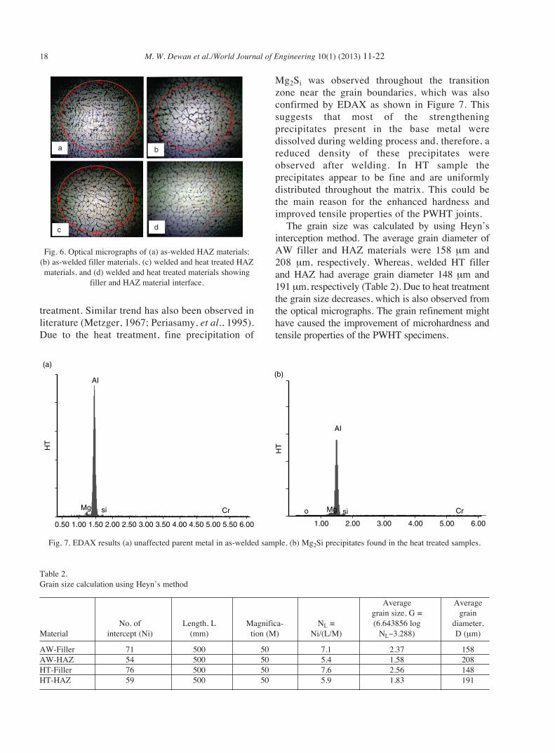
Optical micrographs of the weld metal andHAZ metal of the AW and PWHT samples areshown in Figure 6. All these micrographs weretaken at 50X magnification. Some amount ofgrain-coarsening can be seen in the HAZ area ofAW samples; whereas weld metal in PWHTsamples have a fine grain structure. Figures 6(d)shows grain structure at the transition betweenHAZ and filler materials. The dendritic structuresin HAZ are formed during the solidification ofweld. The dendrite boundaries appear to be brokenup and precipitate in the grain boundary by heat
Fig. 4. Stress-strain diagram along loading direction (a) parallel to weld center line, (b) heat affected zone, (c) perpendicular to weldcenter line, (d) Base metal, perpendicular to weld center line (without heat-treatment and with heat-treatment).
300
(a)
250
200
150
100
50
0
0 0.02
Str
ess
(MP
a)
0.04 0.06Strain (mm/mm)
0.08 0.1 0.12−50
(c)
250
200
150
100
50
0
0 0.01
Str
ess
(MP
a)
0.02 0.03
Strain (mm/mm)
0.04 0.05−50
300
350
(d)
250
200
150
100
50
0
0 0.02
Str
ess
(MP
a)
0.04 0.06Strain (mm/mm)
0.08 0.1 0.12−50
250
(b)
200
150
100
50
0
0 0.02
Str
ess
(MP
a)
0.04 0.06Strain (mm/mm)
Center weld_HT
0.08 0.1 0.140.12−50
Base material Center weld_No HT
Fig. 5. Micro-hardness with measurement position on the weldsection.
130120110100908070605040
−30 −20 −10 0
Distance from weld center (mm)
Mic
roha
rdne
ss (
HV
)
10 20 30
AWBMHT
18 M. W. Dewan et al./World Journal of Engineering 10(1) (2013) 11-22
treatment. Similar trend has also been observed inliterature (Metzger, 1967; Periasamy, et al., 1995).Due to the heat treatment, fine precipitation of
Mg2Si was observed throughout the transitionzone near the grain boundaries, which was alsoconfirmed by EDAX as shown in Figure 7. Thissuggests that most of the strengtheningprecipitates present in the base metal weredissolved during welding process and, therefore, areduced density of these precipitates wereobserved after welding. In HT sample theprecipitates appear to be fine and are uniformlydistributed throughout the matrix. This could bethe main reason for the enhanced hardness andimproved tensile properties of the PWHT joints.
The grain size was calculated by using Heyn’sinterception method. The average grain diameter ofAW filler and HAZ materials were 158 µm and208 µm, respectively. Whereas, welded HT fillerand HAZ had average grain diameter 148 µm and 191 µm, respectively (Table 2). Due to heat treatmentthe grain size decreases, which is also observed fromthe optical micrographs. The grain refinement mighthave caused the improvement of microhardness andtensile properties of the PWHT specimens.
a
c d
b
Fig. 6. Optical micrographs of (a) as-welded HAZ materials;(b) as-welded filler materials, (c) welded and heat treated HAZmaterials, and (d) welded and heat treated materials showing
filler and HAZ material interface.
Fig. 7. EDAX results (a) unaffected parent metal in as-welded sample, (b) Mg2Si precipitates found in the heat treated samples.
0.50 1.00 1.50 2.00
AI
(a)
CrsiMg
2.50 3.00 3.50 4.00 4.50 5.00 5.50 6.00 1.00
o
2.00 3.00
HTHT
4.00 5.00 6.00
AI
(b)
CrMg si
Table 2.Grain size calculation using Heyn’s method
Average Averagegrain size, G = grain
No. of Length, L Magnifica- NL = (6.643856 log diameter,Material intercept (Ni) (mm) tion (M) Ni/(L/M) NL−3.288) D (µm)
AW-Filler 71 500 50 7.1 2.37 158AW-HAZ 54 500 50 5.4 1.58 208HT-Filler 76 500 50 7.6 2.56 148HT-HAZ 59 500 50 5.9 1.83 191
M. W. Dewan et al./World Journal of Engineering 10(1) (2013) 11-22 19
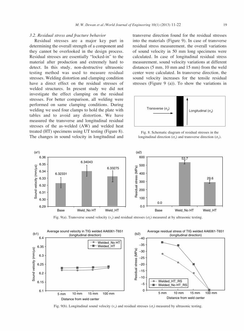
3.2. Residual stress and fracture behaviorResidual stresses are a major key part in
determining the overall strength of a component andthey cannot be overlooked in the design process.Residual stresses are essentially “locked-in” to thematerial after production and extremely hard todetect. In this study, non-destructive ultrasonictesting method was used to measure residualstresses. Welding distortion and clamping conditionhave a direct effect on the residual stresses ofwelded structures. In present study we did notinvestigate the effect clamping on the residualstresses. For better comparison, all welding wereperformed on same clamping conditions. Duringwelding we used four clamps to hold the plate withtables and to avoid any distortion. We havemeasured the transverse and longitudinal residualstresses of the as-welded (AW) and welded heattreated (HT) specimens using UT testing (Figure 8).The changes in sound velocity in longitudinal and
transverse direction found for the residual stressesinto the materials (Figure 9). In case of transverseresidual stress measurement, the overall variationsof sound velocity in 50 mm long specimens werecalculated. In case of longitudinal residual stressmeasurement, sound velocity variations at differentdistances (5 mm, 10 mm and 15 mm) from the weldcenter were calculated. In transverse direction, thesound velocity increases for the tensile residualstresses (Figure 9 (a)). To show the variations in
Transverse (σy) Longitudinal (σx)
Fig. 8. Schematic diagram of residual stresses in thelongitudinal direction (σx) and transverse direction (σy).
6.36 600
500
400
300
200
100
0.0
6.32331
6.34043
6.33275
Base Weld_No HT
Sou
nd v
eloc
ity (
mm
/µs)
Weld_HT Base
Res
idua
l str
ess
(MP
a)
0.0
53.7
29.6
Weld_No HT Weld_HT
6.35
6.34
6.33
6.32
6.31
6.30
6.29
(a1) (a2)
6.4(b1)
Welded_No HTWelded_HT
5 mm
Distance from weld center
10 mm
Average sound velocity in TIG welded AA6061-T651(longitudinal direction)
Average residual stress of TIG welded AA6061-T651(longitudinal direction)
Sou
nd v
eloc
ity (
mm
/µs)
15 mm 100 mm 5 mm
Distance from weld center
10 mm 15 mm 100 mm
6.35
6.3
6.25
6.2
6.15
6.1
−40(b2)
Welded_No HT_RSWelded_HT_RS
Res
idua
l str
ess
(MP
a)
−35
−30
−15
−20
−25
−10
−5
0
Fig. 9(a). Transverse sound velocity (vy) and residual stresses (σy) measured at by ultrasonic testing.
Fig. 9(b). Longitudinal sound velocity (vx) and residual stresses (σy) measured by ultrasonic testing.
20 M. W. Dewan et al./World Journal of Engineering 10(1) (2013) 11-22
sound velocity and residual stresses, error bars(standard deviation) are added. Heat treatmentshowed grain refinement and removal of locked-instresses. Thus lower residual stresses were found inheat-treated specimens compared to AW specimens.In transverse weld direction, average residual was54 MPa and 30 MPa for AW and PWHT specimens,respectively. In longitudinal welding direction,residual stresses at 5 mm, 10 mm, and 15 mm awayfrom the weld center were calculated. Inlongitudinal direction, the sound velocity decreasesdue to the presence of compressive locked-instresses (Figure 9 (b)). The compressive residualstresses were decreased as we moved away from theweld center line. The maximum compressiveresidual stress was obtained 5-mm away from weldcenter line. Average compressive stresses were 35 MPa and 28 MPa for AW and HT specimens,respectively.
To compare the residual stress measured fromultrasonic testing, the hole-drilling method wasused for as-welded (AW) specimens. In this study the residual stress was measured at heat affectedzone (5 mm from center of the weld seam). Theaverage 44 MPa tensile residual stress was foundin the transverse welding direction. Averageresidual stress in the longitudinal direction wascompressive and was −6.5 MPa. Both ultrasonicand hole-drilling tested results are comparable, butthere are few differences. In case of ultrasonictesting we have calculated residual stresses withinthe bulk materials, whereas, in hole-drill method,we have drilled upto a certain depth (equivalent tothe diameter of the strain rosette) for themeasurement of the relaxed residual stresses. Thismight be the reasons for the variations in themeasured results. In case of ultrasonic testing wehave measured average residual stresses 54 MPain transverse direction and −35 MPa inlongitudinal direction for as-welded AA6061-T651 aluminum alloy. Whereas, we obtained 44 MPaand −6.5 MPa residual stresses by using hole-drilling techniques. In case of drill-holetechniques, we calculated the residual stresses upto a depth of 2-mm. The residual stresses dependon depth of the hole. In case of UT, the soundwave passes the full depth of the specimens andresulted bulk residual stresses. That might havecaused the variation between these results. But forcomparison, the results are in same order ofmagnitude and direction (tensile/compressive).
Steves in 2010 showed 40 MPa and −16 MParesidual stresses in transverse and longitudinaldirection, respectively. He calculated residualstresses by using hole-drilling techniques (Steves,2010), which is quite close to our calculatedvalues. Karunakaran and Balasubramanian in2011 calculated residual stress of GTA-weldedAA6351-T6 aluminum alloy using X-ray
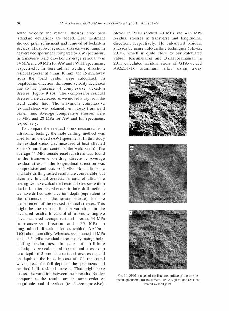
Fig. 10. SEM images of the fracture surface of the tensiletested specimens. (a) Base metal; (b) AW joint, and (c) Heat
treated welded joint.
(a)
(b)
(c)
M. W. Dewan et al./World Journal of Engineering 10(1) (2013) 11-22 21
diffraction method. They obtained residual stress74 MPa in transverse direction, which is also inthe same order of magnitude of our results,although X-ray diffraction results are generallyobtained in the near-surface condition.
The fracture surfaces of the specimens werecharacterized using SEM to understand the failurepatterns. The SEM images (Figure 10 (a, b, c))were taken at the center of the failure surface. Themicrographs indicate that all the surfacesinvariably consist of dimples, which is a typicalindication that most of the failure occurred due toductile fracture. During tensile testing of ductilematerials voids are formed prior to necking. If theneck is formed earlier, the void formation would bemuch more prominent; and as a result coarse andelongated dimples can be seen. Fine dimples werefound on the fracture surfaces of the HT joints. Acomplete characterization of the surface near theroot will be carried out in our future work.
4. ConclusionsIn this research we have studied the effect of heat
treatment on the residual stresses, microstructure,and mechanical performances of GTA-weldedAA6061-T651 aluminum alloy. The followinggeneral conclusions can be made:
The transverse and longitudinal residualstresses were measured by nondestructiveultrasonic testing method. To verify the calculatedresidual stresses semi-destructive drill-holetechnique was used to measure residual stressesand similar overall trends were observed. Sincesound velocity is high, accordingly time requiredto pass the sound waves in a metal is relativelysmall. Therefore, the time-variations due toresidual stresses are also very small. To get goodresults, the equipment for measuring residualstresses must be of high sensitivity and accuracy.For larger specimen, time required to travel soundwaves will be larger and accordingly, we can get abetter change in time variations values andprobably, less error in the results. Very thin andsmall specimen cannot be used to measureresidual stresses accurately with ultrasonic testing.
Using Heyn’s intercept method the grain size offiller and HAZ materials were calculated. The grainsize of materials decreases due to PWHT, which alsoresults reduction in the residual stresses during phasetransformations. By lowering the grain size the inter-
granular stresses can be minimized, which account forthe flaws between grain-boundaries decreasing therisk of failure. This also caused increased tensilestrength properties. The grain refinement andprecipitation results improved microhardness valuesin the welded and HAZ areas.
AcknowledgmentsAuthors gratefully acknowledge the financial
support received from the U.S. Nuclear RegulatoryCommission (NRC) through the grant #NRC-HQ-11-G38-0052. Authors also appreciate the technicalassistances received from Mr. N. Roberts and Mr. A.Kardak with welding and sample preparations.Supports received from Louisiana State University’sDepartment of Mechanical Engineering are gratefullyacknowledged.
ReferencesAjovalasit A., Petrucci G. and Zuccarello B., 1996.
Determination of non-uniform residual stresses using the
ring-core method. J. Eng. Mater. Technol. Trans. ASME
118(2), 224–228.
Ambriz R.R., Barrera G., Garcia R. and Lopez V.H., 2009. A
comparative study of the mechanical properties of 6061-T6
GMA welds obtained by the indirect electric arc (IEA) and
the modified indirect electric arc (MIEA). Mater. Des. 30(7),
2446–2453.
Ahmad R. and Bakar M.A., 2011. Effect of a post-weld heat
treatment on the mechanical and microstructure properties of
AA6061 joints welded by the gas metal arc welding cold
metal transfer method. Mater. Des. 32, 5120–5126.
ASTM, 2004. Standard test methods for tension testing of
metallic materials. ASTM International, West Conshohocken,
PA, USA, pp. 39–51.
Bray D. and Tang W., 2001. Subsurface stress evaluation in
steel plates and bars using the LCR ultrasonic wave. Nucl.
Eng. Des. 27, 231–240.
Clark A. V. and Moulder J. C., 1985. Residual stress
determination in aluminum using electromagnetic acoustic
transducers. Ultrasonics 23(6), 253–259.
Dudas J. H. and Collins F. R., 1966. Preventing weld cracks in
high strength aluminum alloys. Weld J. 45(6), 241–249.
Elangovan K. and Balasubramanian V., 2008. Influences of
post-weld heat treatment on tensile properties of friction stir-
welded AA6061 aluminum alloy joints. Mater. Character.
59(9), 1168–1177.
Gao R.Q., Stiller K., Hansen V., Oskarsson A. and Danoix F.,
2002. Influence of aging conditions on the microstructure
22 M. W. Dewan et al./World Journal of Engineering 10(1) (2013) 11-22
and tensile strength of Aluminium alloy 6063. Mater. Sci.
Forum 396(402), 1211–1216.
Hughes D. S. and Kelly J. L., 1953. Second-order elastic
deformation of solids. Phys. Rev., 92(5), 1145–1149.
Kardak A. and Wahab M. A., 2011. Evolution of mechanical
properties and microstructural characterization of butt
welded AA 6061. Proceedings of 2011 ASME International
Mechanical Engineering Congress and Exposition,
IMECE2011-62247, Denver, Colorado, USA.
Karunakaran N. and Balasubramanian V., 2011. Effect of
pulsed current on temperature distribution, weld bead
profiles and characteristics of gas tungsten arc welded
aluminum alloy joints. Trans. Nonferrous Met. Soc. China
21, 278–286.
Kumar A. and Sundarrajan S., 2006. Selection of welding
process parameters for the optimum butt-joint strength of
an aluminum alloy. Mater. Manufac. Process. 21(8),
pp. 779–782.
Lakshminarayanan A.K., Balasubramanian V. and Elangovan
K., 2009. Effect of welding processes on tensile properties of
AA6061 aluminium alloy joints. Int. J. Adv. Manuf. Technol.
40(3–4), 286–296.
Leggatt R. H., 2008. Residual stresses in welded structures. Int.
J. Press. Ves. Piping 85(3), 144–151.
Liu H.J., Chen Y.C. and Feng J.C., 2006. Effect of heat
treatment on tensile properties of friction stir welded joints
of 2219-T6 aluminium alloy. Mater. Sci. Technol. 22(2),
237–241.
Malin V., 1995. Study of metallurgical phenomena in the HAZ of
6061-T6 aluminum welded joints. Weld. J. 74(9), S305–S318.
Metzger G.E., 1967. Some mechanical properties of welds in
6061 aluminum alloy sheet. Weld. J. 46(10), 457–469.
Periasamy V.M., Sundararajan S., Pathak S.D. and
Radhakrishnan V.M., 1995. Effect of welding and post
weld heat treatment on the tensile and fracture toughness
behavior of Al-Mg-Si alloy. Trans. Indian Inst. Met. 48(5),
373–382.
Ren S., Ma Z., Chen L. and Zhang Y., 2007. Effects of post-
weld heat-treatment and second-welding on tensile
properties of friction stir welded 7075-T651 aluminum alloy.
Acta Metallur. Sinica 43(3), 225–230.
Rossini N.S., Dassisti M., Benyounis K.Y. and Olabi A.G.,
2012. Methods of measuring residual stresses in
components. Mater. Des. 35, 572–588.
Sanderson R.M. and Shen Y.C., 2010. Measurement of residual
stress using laser-generated ultrasound. Int. J. Press. Ves.
Piping 87(12), 762–765.
Steves D., 2010. Characterization of residual stresses and
mechanical performance of gas Tungsten arc welded
Aluminum alloy 6061-T6. Master’s Thesis, Texas Tech
University, Texas, USA.
Tan C.F. and Said M.R., 2009. Effect of hardness test on
precipitation hardening Aluminum alloy 6061-T6. Chiang
Mai J. Sci. 36(3), 276–286.
Thompson R.B., Liu, W.Y. and Clark A.V., 1996. Handbook of
measurement of residual stresses. Society of Experimental
Mechanics, Bethel, pp. 45–71.
Uzun F. and Bilge A.N., 2011. Immersion ultrasonic technique
for investigation of total welding residual stress. Proc. Eng.
10, 3098–3103.