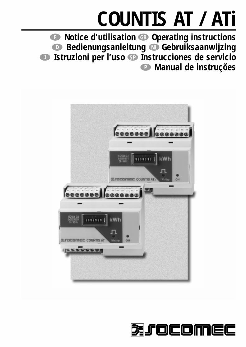
COUNTIS AT / ATiNotice d’utilisation Operating instructionsBedienungsanleitung Gebruiksaanwijzing
Istruzioni per l’uso Instrucciones de servicioManual de instruções
F GB
NLD
SP
P
I
FSo
mm
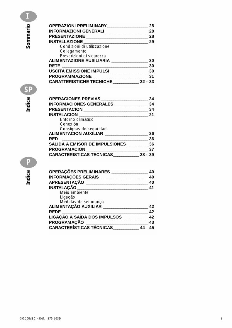
aire OPÉRATIONS PRÉALABLES ____________________ 4
INFORMATIONS GÉNÉRALES___________________ 4PRESENTATION _______________________________ 4INSTALLATION ________________________________ 5
Environnement climatiqueRaccordementConsignes de sécurité
ALIMENTATION AUXILIAIRE ____________________ 6RÉSEAU_______________________________________ 6SORTIE À ÉMETTEUR D’IMPULSION____________ 6PROGRAMMATION ____________________________ 7CARACTÉRISTIQUES TECHNIQUES _________ 8 - 9
GB
Cont
ents PRELIMINARY OPERATIONS __________________10
GENERAL INFORMATIONS ____________________ 10PRESENTATION ______________________________ 10INSTALLATION _______________________________ 11
Climatic environmentConnectionSafety instructions
AUXILIARY POWER SUPPLY___________________ 12NETWORK ___________________________________ 12PULSE TRANSMITTER OUTPUT _______________ 12PROGRAMMING______________________________ 13TECHNICAL CHARACTERISTICS __________ 14 - 15
D
Inha
ltsve
rzei
chni
s VORAUSGEHENDE KONTROLLEN _____________ 16ALLGEMEINE HINWEISE ______________________ 16PRODUKTDARSTELLUNG_____________________ 16INSTALLATION _______________________________ 17
Klimatische BedingungenAnschlüsseSicherheitshinweis
HILFSSPANNUNG_____________________________ 18NETZ ________________________________________ 18IMPULSAUSGANG ____________________________ 18PROGRAMMIERUNG__________________________ 19TECHNISCHE DATEN _____________________ 20 - 21
NL
Inho
ud VOORAFGAANDE HANDELINGEN _____________ 22 ALGEMENE INFORMATIE _____________________ 22VOORSTELLING ______________________________ 22INSTALLATIE _________________________________ 23
OmgevingstemperatuurAansluitingVeiligheidsvoorschriften
HULPVOEDING _______________________________ 24NET ________________________________________ 24IMPULSUITGANG_____________________________ 24PROGRAMMEREN ____________________________ 25TECHNISCHE EIGENSCHAPPEN __________ 26 - 27
SOCOMEC - Réf. : 875 503D 3
SP
Indi
ce OPERACIONES PREVIAS______________________ 34INFORMACIONES GENERALES________________ 34PRESENTACION ______________________________ 34INSTALACION ________________________________ 21
Entorno climáticoConexiónConsignas de seguridad
ALIMENTACION AUXILIAR ____________________ 36RED ________________________________________ 36SALIDA A EMISOR DE IMPULSIONES __________ 36PROGRAMACION_____________________________ 37CARACTERISTICAS TECNICAS____________ 38 - 39
P
Indi
ce OPERAÇÕES PRELIMINARES _________________ 40INFORMAÇÕES GERAIS ______________________ 40APRESENTAÇÃO _____________________________ 40INSTALAÇÃO _________________________________ 41
Meio ambienteLigaçãoMedidas de segurança
ALIMENTAÇÃO AUXILIAR _____________________ 42REDE ________________________________________ 42LIGAÇÃO À SAÍDA DOS IMPULSOS____________ 42PROGRAMAÇÃO _____________________________ 43CARACTERÍSTICAS TÉCNICAS____________ 44 - 45
ISo
mm
ario OPERAZIONI PRELIMINARY___________________ 28
INFORMAZIONI GENERALI ____________________ 28PRESENTAZIONE _____________________________ 28INSTALLAZIONE ______________________________ 29
Condizioni di utilizzazioneCollegamentoPrescrizioni di sicurezza
ALIMENTAZIONE AUSILIARIA _________________ 30RETE ________________________________________ 30USCITA EMISSIONE IMPULSI__________________ 30PROGRAMMAZIONE__________________________ 31CARATTERISTICHE TECNICHE____________ 32 - 33
4 SOCOMEC - Réf. : 875 503D
INFORMATIONS GÉNÉRALESLe système COUNTIS est composé deproduits assurant le comptage de l’éner-gie pour des réseaux électriques BT 3 ou4 fils équilibré ou non. Ce système estcomposé de 2 produits :• L’AT : compteur d’énergie Active
Triphasé non isolé ne permettant pasle raccordement du secondaire des TCà la terre
• L’ATi : compteur d’énergie ActiveTriphasé isolé permettant le raccorde-ment du secondaire des TC à la terre.
Ces produits sont entièrement configu-rables (rapport de TC, type de réseau etpoids de la sortie impulsions) et permet-tent, à partir d’un afficheur de 7 digits,de visualiser directement la consom-mation en kWh. Ils sont équipés enstandard d’une sortie impulsions (2 en option).
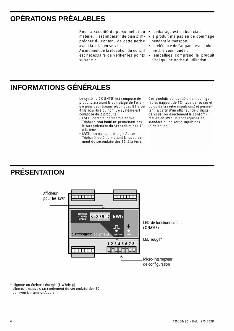
PRÉSENTATION
Micro-interrupteurde configuration
Afficheurpour les kWh
LED de fonctionnement(ON/OFF)
LED rouge*COUNTIS AT
1 2 3 4 5 6 7 8
* clignote ou éteinte : énergie (1 Wh/imp)allumée : mauvais raccordement du secondaire des TCou inversion tension/courant
Pour la sécurité du personnel et dumatériel, il est impératif de bien s’im-prégner du contenu de cette noticeavant la mise en service.Au moment de la réception du colis, ilest nécessaire de vérifier les pointssuivants :
• l’emballage est en bon état,• le produit n’a pas eu de dommage
pendant le transport,• la référence de l’appareil est confor-
me à la commande ;• l’emballage comprend le produit
ainsi qu’une notice d’utilisation.
OPÉRATIONS PRÉALABLES
SOCOMEC - Réf. : 875 503D 5
FRAN
ÇAIS
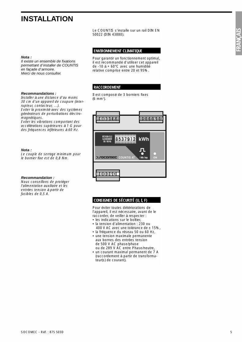
INSTALLATIONLe COUNTIS s’installe sur un rail DIN EN50022 (DIN 43880).
Pour éviter toutes détériorations del’appareil, il est nécessaire, avant de leraccorder, de veiller à respecter :• les indications sur le boîtier,• la tension d’alimentation : 230 ou
400 V AC avec une tolérance de ± 15%,• la fréquence du réseau 50 ou 60 Hz,• une tension maximale permanente
aux bornes des entrées tension de 500 V AC phase/phase ou de 289 V AC entre Phase/neutre,
• un courant maximal permanent de 7 A(raccordement à partir de transforma-teur(s) de courant).
CONSIGNES DE SÉCURITÉ (U, I, F)
Nota :Il existe un ensemble de fixationspermettant d’installer de COUNTIS en façade d’armoire.Merci de nous consulter.
Nota :Le couple de serrage minimum pourle bornier fixe est de 0,8 Nm.
Recommandation :Nous conseillons de protégerl’alimentation auxiliaire et lesentrées tension à partir defusibles de 0,5 A.
Recommandations :Installer à une distance d’au moins30 cm d’un appareil de coupure (inter-rupteur, contacteur, …).Eviter la proximité avec des systèmesgénérateurs de perturbations électro-magnétiques.Eviter les vibrations comportant desaccélérations supérieures à 1 G pourdes fréquences inférieures à 60 Hz.
Pour garantir un fonctionnement optimal,il est recommandé d’utiliser cet appareilde -10 à + 60°C avec une humiditérelative comprise entre 20 et 95%.
ENVIRONNEMENT CLIMATIQUE
Il est composé de 3 borniers fixes (6 mm2).
RACCORDEMENT
COUNTIS AT
16 15171819202112 131485211
976431
6 SOCOMEC - Réf. : 875 503D
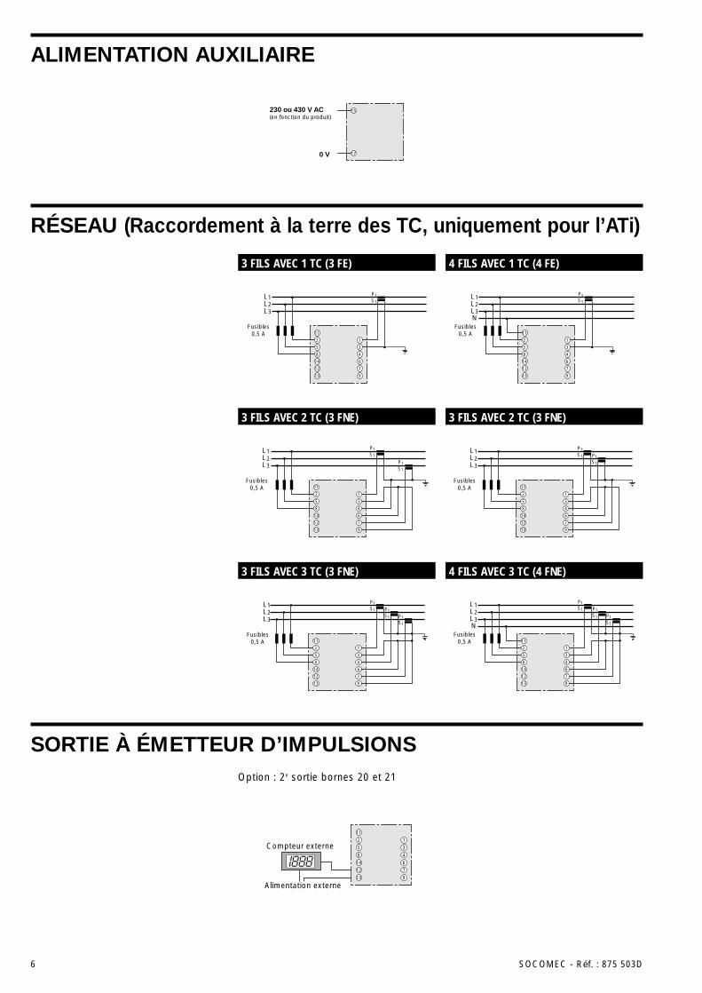
ALIMENTATION AUXILIAIRE
RÉSEAU (Raccordement à la terre des TC, uniquement pour l’ATi)
SORTIE À ÉMETTEUR D’IMPULSIONS
L1L2L3
P1S1
P1S1
P1S1
11
2
5
8
14
12
13
1
3
4
6
7
9
Fusibles0,5 A
L1L2L3
P1S1
P1S1
11
2
5
8
14
12
13
1
3
4
6
7
9
Fusibles0,5 A
11
14
12
13
4
6
7
9
L1L2L3
P1S1
2
5
8
1
3
Fusibles0,5 A
L1L2L3
P1S1
P1S1
11
2
5
8
14
12
13
1
3
4
6
7
9
Fusibles0,5 A
L1L2L3N
Fusibles0,5 A
P1S1
P1S1
P1S1
11
2
5
8
14
12
13
1
3
4
6
7
9
L1L2L3N
P1S1
11
2
5
8
14
12
13
1
3
4
6
7
9
Fusibles0,5 A
Compteur externe
11
2
5
8
14
12
13
1
3
4
6
7
9
Alimentation externe
230 ou 430 V AC(en fonction du produit)
0 V
15
17
3 FILS AVEC 1 TC (3 FE) 4 FILS AVEC 1 TC (4 FE)
3 FILS AVEC 2 TC (3 FNE) 3 FILS AVEC 2 TC (3 FNE)
3 FILS AVEC 3 TC (3 FNE) 4 FILS AVEC 3 TC (4 FNE)
Option : 2e sortie bornes 20 et 21
SOCOMEC - Réf. : 875 503D 7
FRAN
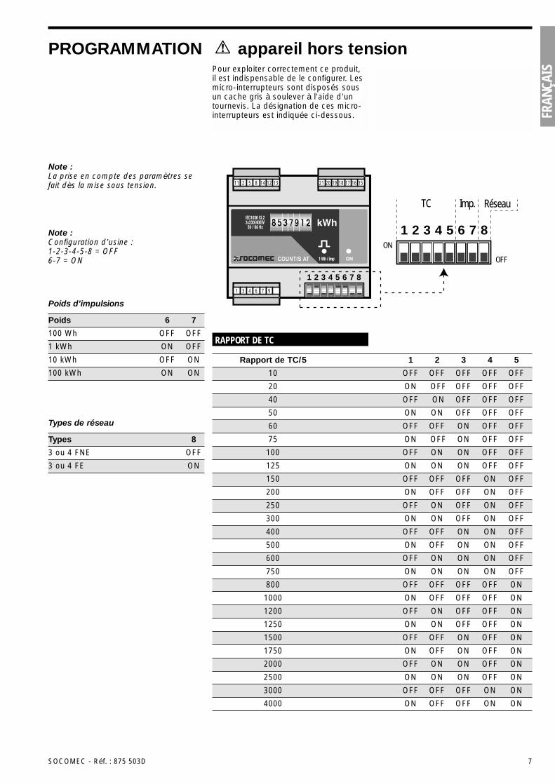
ÇAISPour exploiter correctement ce produit,
il est indispensable de le configurer. Lesmicro-interrupteurs sont disposés sousun cache gris à soulever à l’aide d’untournevis. La désignation de ces micro-interrupteurs est indiquée ci-dessous.
PROGRAMMATION appareil hors tension
Note :La prise en compte des paramètres sefait dès la mise sous tension.
Note :Configuration d’usine :1-2-3-4-5-8 = OFF6-7 = ON
Poids d’impulsions
100 Wh OFF OFF
1 kWh ON OFF
Poids 6 7
10 kWh OFF ON
100 kWh ON ON
Types de réseau
3 ou 4 FNE OFF
3 ou 4 FE ON
Types 8
1
TC Imp. Réseau
2 3 4 5 6 7 8ON
OFFCOUNTIS AT
16 15171819202112 131485211
976431
1 2 3 4 5 6 7 8
RAPPORT DE TC
10 OFF OFF OFF OFF OFF
40 OFF ON OFF OFF OFF
Rapport de TC/5 1 2 3 4 5
20 ON OFF OFF OFF OFF
50 ON ON OFF OFF OFF
60 OFF OFF ON OFF OFF
75 ON OFF ON OFF OFF
100 OFF ON ON OFF OFF
125 ON ON ON OFF OFF
200 ON OFF OFF ON OFF
300 ON ON OFF ON OFF
500 ON OFF ON ON OFF
750 ON ON ON ON OFF
1000 ON OFF OFF OFF ON
1250 ON ON OFF OFF ON
1750 ON OFF ON OFF ON
2500 ON ON ON OFF ON
4000 ON OFF OFF ON ON
150 OFF OFF OFF ON OFF
250 OFF ON OFF ON OFF
400 OFF OFF ON ON OFF
600 OFF ON ON ON OFF
800 OFF OFF OFF OFF ON
1200 OFF ON OFF OFF ON
1500 OFF OFF ON OFF ON
2000 OFF ON ON OFF ON
3000 OFF OFF OFF ON ON
8 SOCOMEC - Réf. : 875 503D
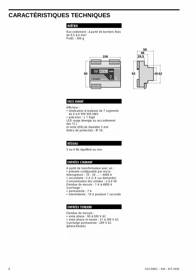
CARACTÉRISTIQUES TECHNIQUES
Raccordement : à partir de borniers fixesde 0,5 à 6 mm2
Poids : 300 g
BOÎTIER
3 ou 4 fils équilibré ou non.
RÉSEAU
Afficheur :• totalisateur à rouleaux de 7 segments
de 0 à 9 999 999 kWh• précision : ± 1 DigitLED rouge (énergie ou raccordement des TC)et verte (ON) de diamètre 5 mmIndice de protection : IP 54.
FACE AVANT
Etendue de mesure :• entre phase : 90 à 500 V AC• entre phase et neutre : 51 à 289 V ACSurcharge permanente : 289 V AC(phase/neutre)
ENTRÉES TENSION
A partir de transformateur avec un :• primaire configurable par micro-interrupteurs : 10 - 20 … – 4000 A• secondaire : 5 A (1 A sur demande)Consommation des entrées : ≤ 0,4 VAEtendue de mesure : 1 A à 4800 ASurcharge :• permanente : 7 A• intermittente : 10 A pendant 1 seconde
ENTRÉES COURANT
106 26,548
58
90 93 45 62COUNTIS AT
SOCOMEC - Réf. : 875 503D 9
FRAN
ÇAIS
CARACTÉRISTIQUES TECHNIQUES (suite)
Energie active : CEI 1036 en classe 1pour l’ATi et en classe 2 pour l’AT
PRÉCISION
230 V ou 400 V AC, 50/60 HzTolérance : ± 15 %Consommation : 4 VA
ALIMENTATION AUXILIAIRE
Relais reed 1 T (100 V DC - 0,5 A - 10 VA)Durée d’impulsions : 100 msNombre de manœuvres : 100 x 106 mini-mumPoids d’impulsions programmable parmicro-interrupteurs : 100 Wh / 1 kWh /10 kWh / 100 kWh2e sortie impulsions (option) :• raccordée en parallèle sur la première• indépendante de la première (surdemande)
SORTIE IMPULSIONS
Alimentation auxiliaire : 2,5 kV AC pendant 1 minuteEntrées courant : 2,5 kV AC pendant 1 minuteSortie impulsions : 2,5 kV AC pendant 1 minute
ISOLATION GALVANIQUE
Relative à la précision sur l’énergieactive :• CEI 1036 en classe 1 pour l’ATi et en classe 2 pour l’ATRelative au marquage CE :• EN 50081-2• EN 50082-2• CEI 1000-4-2/3-4-5-6-8-11Relative aux conditions d’utilisation :• CEI 68-2-11/30
NORMES
Température de fonctionnement : -10 à+60°CTempérature de stockage : -20 à +70°CHumidité relative : 95%
CONDITIONS D’UTILISATION
10 SOCOMEC - Réf. : 875 503D
GENERAL INFORMATIONSThe COUNTIS System comprises energymetering products for balanced or non-balanced 3- or 4-wire network. Thissystem comprises two products:• AT: a non-insulated three-phase
active energy-meter, which does notallow earthing CT of secondary (class 2).
• ATi: an Insulated three-phase activeenergy meter, which allows earthing CTof secondary (class 1 IEC 1036).
These products are completely confi-gurable (CT radio, network type andpulse output value) and have a 7-digitdisplay which allows direct display ofconsumption in kWh. They are equippedwith a pulse output as standard (2 as an option).
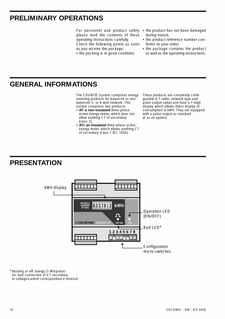
PRESENTATION
Configuration micro-switches
kWh display
Operation LED(ON/OFF)
Red LED*COUNTIS AT
1 2 3 4 5 6 7 8
* flashing or off: energy (1 Wh/pulse)on: bad connection of CT secondaryor voltage/current correspondance reversal
For personnel and product safetyplease read the contents of theseoperating instructions carefully.Check the following points as soonas you receive the package:• the packing is in good condition,
• the product has not been damagedduring transit,
• the product reference number con-forms to your order,
• the package contains the productas well as the operating instructions.
PRELIMINARY OPERATIONS
ENGL
ISH
SOCOMEC - Réf. : 875 503D 11
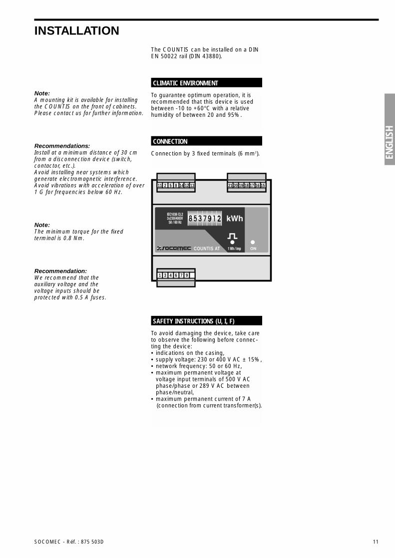
INSTALLATIONThe COUNTIS can be installed on a DINEN 50022 rail (DIN 43880).
To avoid damaging the device, take careto observe the following before connec-ting the device:• indications on the casing,• supply voltage: 230 or 400 V AC ± 15%,• network frequency: 50 or 60 Hz,• maximum permanent voltage at
voltage input terminals of 500 V ACphase/phase or 289 V AC betweenphase/neutral,
• maximum permanent current of 7 A (connection from current transformer(s).
SAFETY INSTRUCTIONS (U, I, F)
Note:A mounting kit is available for installingthe COUNTIS on the front of cabinets.Please contact us for further information.
Note:The minimum torque for the fixedterminal is 0.8 Nm.
Recommendation:We recommend that theauxiliary voltage and thevoltage inputs should beprotected with 0.5 A fuses.
Recommendations:Install at a minimum distance of 30 cmfrom a disconnection device (switch,contactor, etc.).Avoid installing near systems whichgenerate electromagnetic interference.Avoid vibrations with acceleration of over1 G for frequencies below 60 Hz.
To guarantee optimum operation, it isrecommended that this device is usedbetween -10 to +60°C with a relativehumidity of between 20 and 95%.
CLIMATIC ENVIRONMENT
Connection by 3 fixed terminals (6 mm2).
CONNECTION
COUNTIS AT
16 15171819202112 131485211
976431
12 SOCOMEC - Réf. : 875 503D
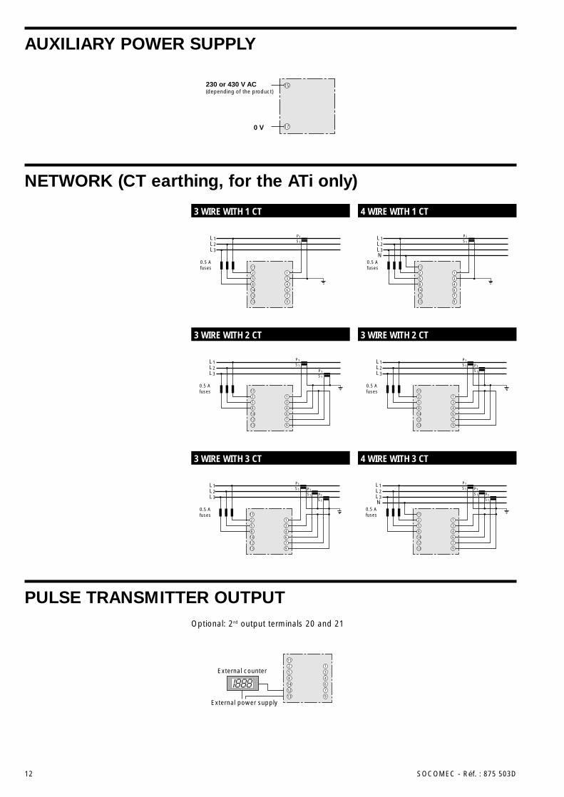
AUXILIARY POWER SUPPLY
NETWORK (CT earthing, for the ATi only)
PULSE TRANSMITTER OUTPUT
L1L2L3
P1S1
P1S1
P1S1
11
2
5
8
14
12
13
1
3
4
6
7
9
0.5 Afuses
L1L2L3
P1S1
P1S1
11
2
5
8
14
12
13
1
3
4
6
7
9
0.5 Afuses
11
14
12
13
4
6
7
9
L1L2L3
P1S1
2
5
8
1
3
0.5 Afuses
L1L2L3
P1S1
P1S1
11
2
5
8
14
12
13
1
3
4
6
7
9
0.5 Afuses
L1L2L3N
0.5 Afuses
P1S1
P1S1
P1S1
11
2
5
8
14
12
13
1
3
4
6
7
9
L1L2L3N
P1S1
11
2
5
8
14
12
13
1
3
4
6
7
9
0.5 Afuses
External counter
11
2
5
8
14
12
13
1
3
4
6
7
9
External power supply
230 or 430 V AC(depending of the product)
0 V
15
17
3 WIRE WITH 1 CT 4 WIRE WITH 1 CT
3 WIRE WITH 2 CT 3 WIRE WITH 2 CT
3 WIRE WITH 3 CT 4 WIRE WITH 3 CT
Optional: 2nd output terminals 20 and 21
ENGL
ISH
SOCOMEC - Réf. : 875 503D 13
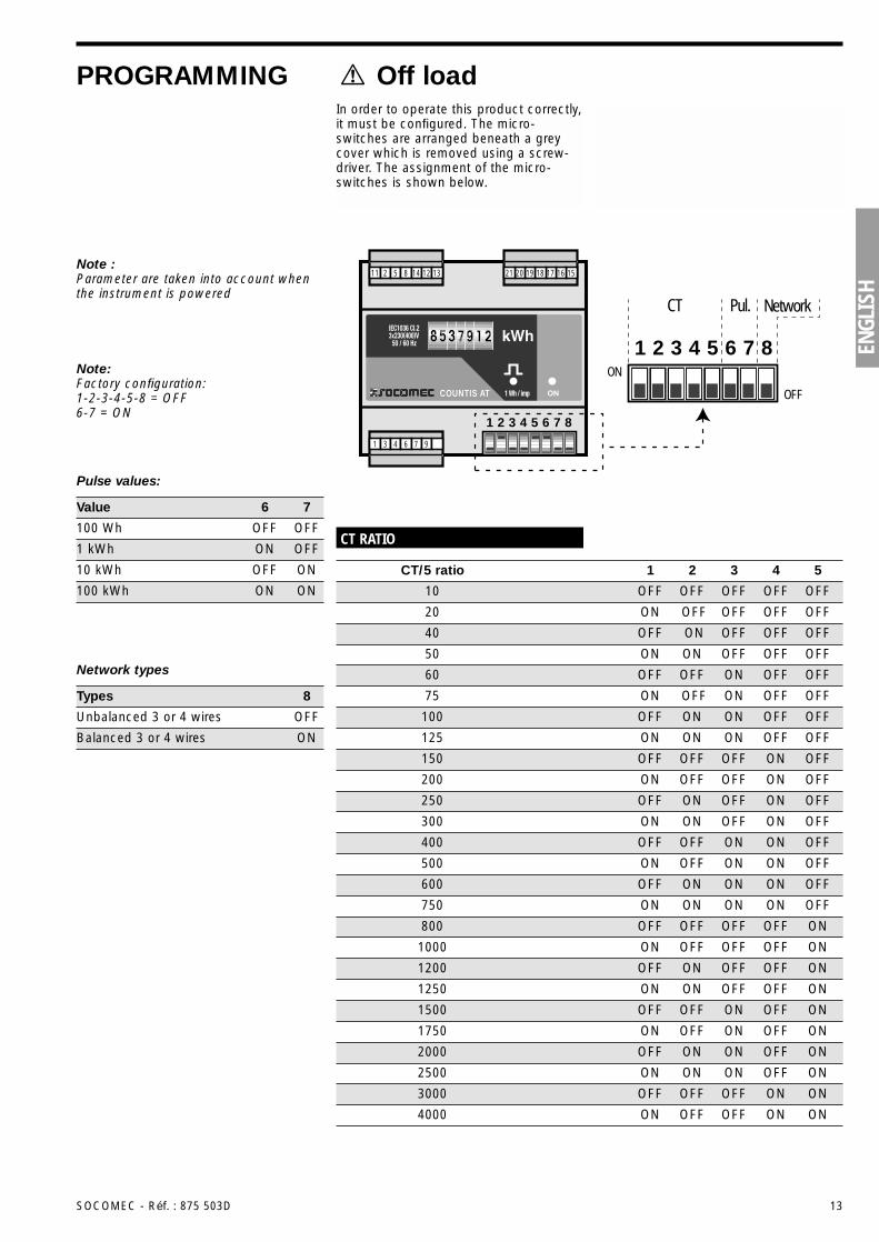
PROGRAMMING Off loadIn order to operate this product correctly,it must be configured. The micro-switches are arranged beneath a greycover which is removed using a screw-driver. The assignment of the micro-switches is shown below.
1
CT Pul. Network
2 3 4 5 6 7 8ON
OFFCOUNTIS AT
16 15171819202112 131485211
976431
1 2 3 4 5 6 7 8
CT RATIO
10 OFF OFF OFF OFF OFF
40 OFF ON OFF OFF OFF
CT/5 ratio 1 2 3 4 5
20 ON OFF OFF OFF OFF
50 ON ON OFF OFF OFF
60 OFF OFF ON OFF OFF
75 ON OFF ON OFF OFF
100 OFF ON ON OFF OFF
125 ON ON ON OFF OFF
200 ON OFF OFF ON OFF
300 ON ON OFF ON OFF
500 ON OFF ON ON OFF
750 ON ON ON ON OFF
1000 ON OFF OFF OFF ON
1250 ON ON OFF OFF ON
1750 ON OFF ON OFF ON
2500 ON ON ON OFF ON
4000 ON OFF OFF ON ON
150 OFF OFF OFF ON OFF
250 OFF ON OFF ON OFF
400 OFF OFF ON ON OFF
600 OFF ON ON ON OFF
800 OFF OFF OFF OFF ON
1200 OFF ON OFF OFF ON
1500 OFF OFF ON OFF ON
2000 OFF ON ON OFF ON
3000 OFF OFF OFF ON ON
Note :Parameter are taken into account whenthe instrument is powered
Note:Factory configuration:1-2-3-4-5-8 = OFF6-7 = ON
Pulse values:
100 Wh OFF OFF
1 kWh ON OFF
Value 6 7
10 kWh OFF ON
100 kWh ON ON
Network types
Unbalanced 3 or 4 wires OFF
Balanced 3 or 4 wires ON
Types 8
14 SOCOMEC - Réf. : 875 503D
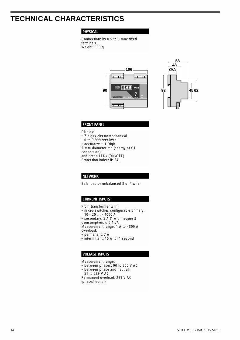
TECHNICAL CHARACTERISTICS
Connection: by 0.5 to 6 mm2 fixedterminals.Weight: 300 g
PHYSICAL
Balanced or unbalanced 3 or 4 wire.
NETWORK
Display:• 7 digits electromechanical
0 to 9 999 999 kWh• accuracy: ± 1 Digit5-mm diameter red (energy or CTconnection)and green LEDs (ON/OFF)Protection index: IP 54.
FRONT PANEL
Measurement range:• between phases: 90 to 500 V AC• between phase and neutral:
51 to 289 V ACPermanent overload: 289 V AC(phase/neutral)
VOLTAGE INPUTS
From transformer with:• micro-switches configurable primary:
10 - 20 … - 4000 A• secondary: 5 A (1 A on request)Consumption: ≤ 0,4 VAMeasurement range: 1 A to 4800 AOverload:• permanent: 7 A• intermittent: 10 A for 1 second
CURRENT INPUTS
106 26,548
58
90 93 45 62COUNTIS AT
ENGL
ISH
SOCOMEC - Réf. : 875 503D 15
TECHNICAL CHARACTERISTICS
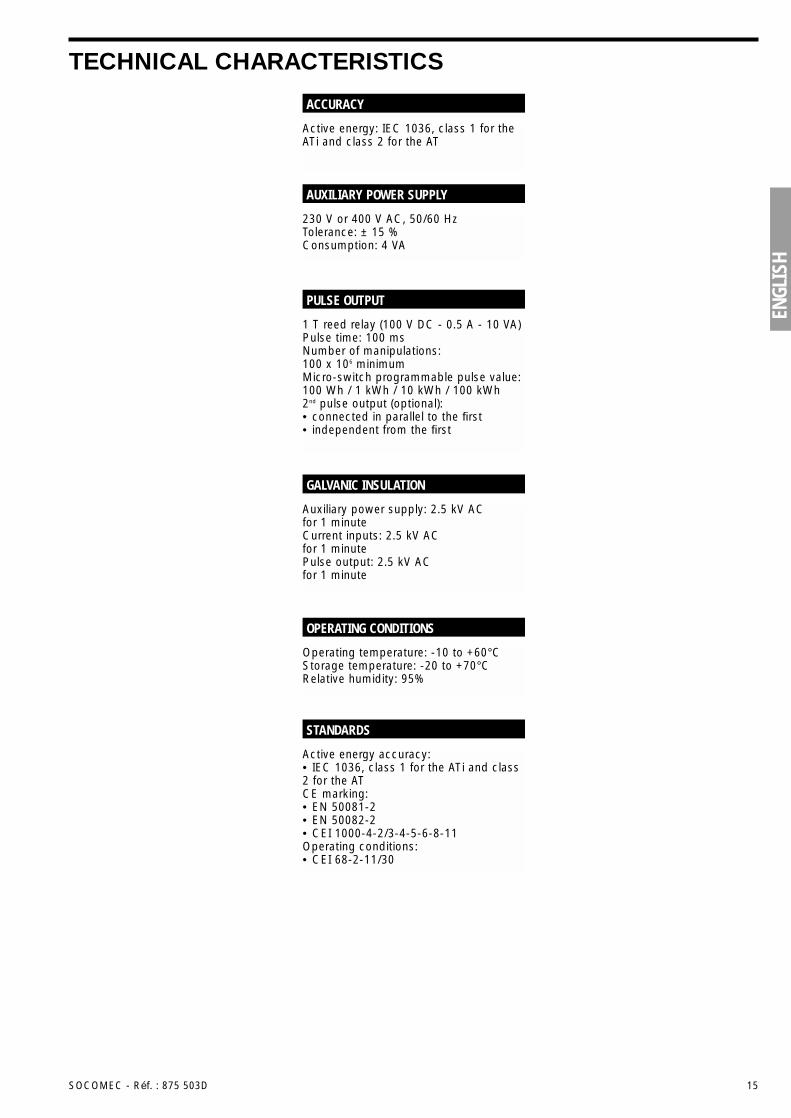
Active energy: IEC 1036, class 1 for theATi and class 2 for the AT
ACCURACY
230 V or 400 V AC, 50/60 HzTolerance: ± 15 %Consumption: 4 VA
AUXILIARY POWER SUPPLY
1 T reed relay (100 V DC - 0.5 A - 10 VA)Pulse time: 100 msNumber of manipulations: 100 x 106 minimumMicro-switch programmable pulse value:100 Wh / 1 kWh / 10 kWh / 100 kWh2nd pulse output (optional):• connected in parallel to the first• independent from the first
PULSE OUTPUT
Auxiliary power supply: 2.5 kV AC for 1 minuteCurrent inputs: 2.5 kV AC for 1 minutePulse output: 2.5 kV AC for 1 minute
GALVANIC INSULATION
Active energy accuracy:• IEC 1036, class 1 for the ATi and class2 for the ATCE marking:• EN 50081-2• EN 50082-2• CEI 1000-4-2/3-4-5-6-8-11Operating conditions:• CEI 68-2-11/30
STANDARDS
Operating temperature: -10 to +60°CStorage temperature: -20 to +70°CRelative humidity: 95%
OPERATING CONDITIONS
16 SOCOMEC - Réf. : 875 503D
ALLGEMEINE HINWEISEDas COUNTIS-System besteht ausProdukten, die es ermöglichen dieEnergie von gleich oder ungleich belas-teten elektrischen NS-Netzen zu zählen.Es besteht aus zwei Typen:• Der AT: nicht isolierter aktiv
Dreiphasen-Energiezähler, der es nichtgestattet, die Sekundärseite desStromwandlers an Erde anzuschließen
• Der ATi: isolierter aktiv Dreiphasen-Energiezähler, der es gestattet, dieSekundärseite des Stromwandlers anErde anzuschließen.
Diese Produkte sind vollständig konfigu-rierbar (Stromwandlerverhältnis, Netztypund Gewichtung des Impulsausgangs)und erlaubt es, anhand einer Anzeige mit7 Digit den Energieverbrauch in kWhabzulesen. Sie sind standardmäßig mit einem Impulsausgang bestückt (2 Impulsausgänge optional).
PRODUKTDARSTELLUNG
Konfigurationsmicroschalter
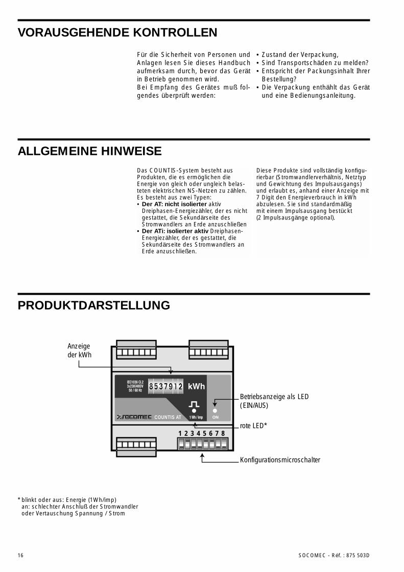
Anzeigeder kWh
Betriebsanzeige als LED(EIN/AUS)
rote LED*COUNTIS AT
1 2 3 4 5 6 7 8
* blinkt oder aus: Energie (1Wh/imp)an: schlechter Anschluß der Stromwandleroder Vertauschung Spannung / Strom
Für die Sicherheit von Personen undAnlagen lesen Sie dieses Handbuchaufmerksam durch, bevor das Gerätin Betrieb genommen wird.Bei Empfang des Gerätes muß fol-gendes überprüft werden:
• Zustand der Verpackung,• Sind Transportschäden zu melden?• Entspricht der Packungsinhalt Ihrer
Bestellung?• Die Verpackung enthählt das Gerät
und eine Bedienungsanleitung.
VORAUSGEHENDE KONTROLLEN
DEUT
SCH
SOCOMEC - Réf. : 875 503D 17
INSTALLATIONDas COUNTIS wird auf einer DIN-Schiene befestigt (EN 50022 DIN 43880).
Um jegliche Beschädigung des Gerätesvor dem Anschließen zu vermeiden,beachten Sie bitte folgendes:• die Angaben auf dem Gehäuse• die Spannungsversorgung: 230 oder
400 V AC mit einer Toleranz von ±15%• Netzfrequenz: 50 oder 60 Hz• Eine Dauerwechselspannung an den
Spannungseingängen von 500 V ACPhase/Phase oder 289 V AC zwischenPhase und Null
• ein Maximaldauerstrom von 7A(Anschluß ausgehend vomStromwandlerausgang).
SICHERHEITSHINWEIS (U, I, F)
Anmerkung:Es gibt eine Vorrichtung, die esermöglicht das COUNTIS an der Frontdes Schrankes anzubringen.Bitte anfragen.
Hinweis:Das maximale Anzugsmoment für die Anschlußklemmen beträgt 0,8Nm.
Empfehlung:Wir empfehlen einen Schutzder externen Versorgung und den Spannungseingängenmit einer Sicherung von 0,5 A.
Empfehlung:Installation des Gerätes mit einemMindestabstand von 30 cm zu einemSchaltgerät (Schalter, Schütz…).Vermeiden Sie die Nähe von Systemen,die elektromagnetische Störungenerzeugen können.Vermeiden Sie Vibrationen mitBeschleunigungen größer 1G beiFrequenzen kleiner 60Hz.
Um eine optimale Funktionsweise zugewährleisten empfehlen wir diesesGerät bei -10°C bis +60°C bei einerrelativen Luftfeuchtigkeit zwischen 20%und 95% zu betreiben.
KLIMATISCHE BEDINGUNGEN
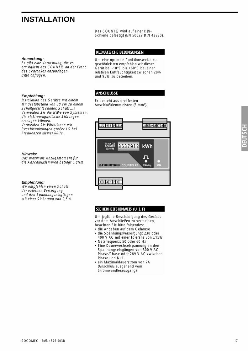
Er besteht aus drei festenAnschlußklemmleisten (6 mm2).
ANSCHLÜSSE
COUNTIS AT
16 15171819202112 131485211
976431
18 SOCOMEC - Réf. : 875 503D
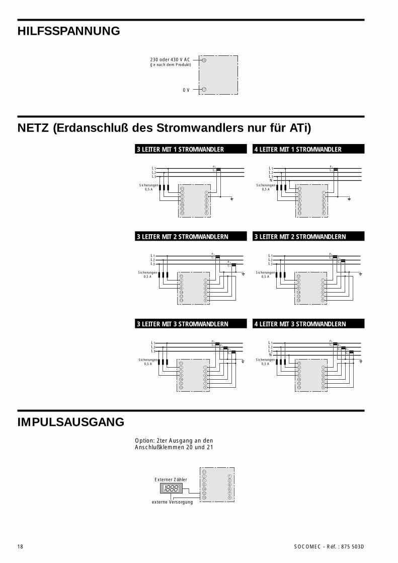
HILFSSPANNUNG
NETZ (Erdanschluß des Stromwandlers nur für ATi)
IMPULSAUSGANG
L1L2L3
P1S1
P1S1
P1S1
11
2
5
8
14
12
13
1
3
4
6
7
9
Sicherungen0,5 A
L1L2L3
P1S1
P1S1
11
2
5
8
14
12
13
1
3
4
6
7
9
Sicherungen0,5 A
11
14
12
13
4
6
7
9
L1L2L3
P1S1
2
5
8
1
3
Sicherungen0,5 A
L1L2L3
P1S1
P1S1
11
2
5
8
14
12
13
1
3
4
6
7
9
Sicherungen0,5 A
L1L2L3N
Sicherungen0,5 A
P1S1
P1S1
P1S1
11
2
5
8
14
12
13
1
3
4
6
7
9
L1L2L3N
P1S1
11
2
5
8
14
12
13
1
3
4
6
7
9
Sicherungen0,5 A
Externer Zähler
11
2
5
8
14
12
13
1
3
4
6
7
9
externe Versorgung
230 oder 430 V AC(Je nach dem Produkt)
0 V
15
17
3 LEITER MIT 1 STROMWANDLER 4 LEITER MIT 1 STROMWANDLER
3 LEITER MIT 2 STROMWANDLERN 3 LEITER MIT 2 STROMWANDLERN
3 LEITER MIT 3 STROMWANDLERN 4 LEITER MIT 3 STROMWANDLERN
Option: 2ter Ausgang an denAnschlußklemmen 20 und 21
DEUT
SCH
SOCOMEC - Réf. : 875 503D 19
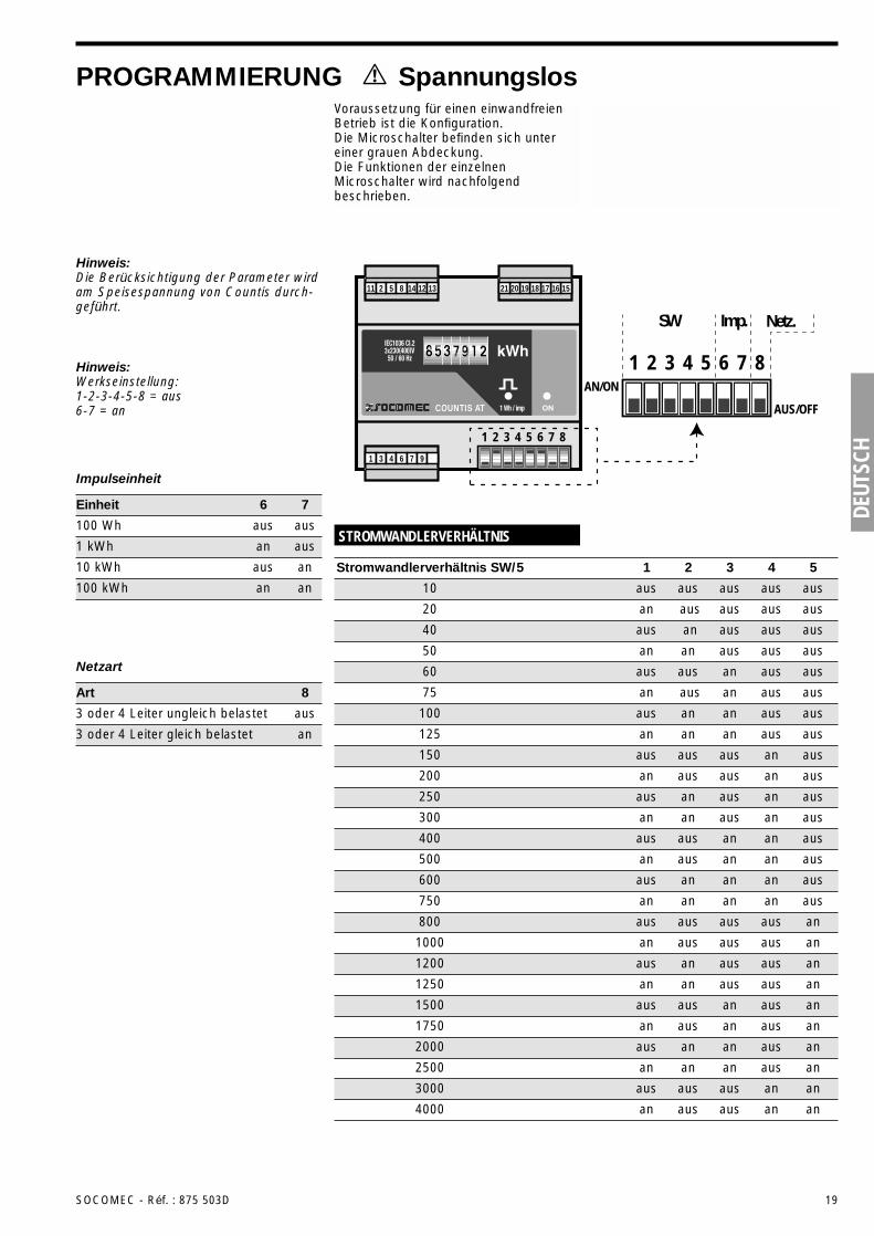
PROGRAMMIERUNG SpannungslosVoraussetzung für einen einwandfreienBetrieb ist die Konfiguration. Die Microschalter befinden sich untereiner grauen Abdeckung. Die Funktionen der einzelnenMicroschalter wird nachfolgendbeschrieben.
1
SW Imp. Netz.
2 3 4 5 6 7 8AN/ON
AUS/OFFCOUNTIS AT
16 15171819202112 131485211
976431
1 2 3 4 5 6 7 8
STROMWANDLERVERHÄLTNIS
10 aus aus aus aus aus
40 aus an aus aus aus
Stromwandlerverhältnis SW/5 1 2 3 4 5
20 an aus aus aus aus
50 an an aus aus aus
60 aus aus an aus aus
75 an aus an aus aus
100 aus an an aus aus
125 an an an aus aus
200 an aus aus an aus
300 an an aus an aus
500 an aus an an aus
750 an an an an aus
1000 an aus aus aus an
1250 an an aus aus an
1750 an aus an aus an
2500 an an an aus an
4000 an aus aus an an
150 aus aus aus an aus
250 aus an aus an aus
400 aus aus an an aus
600 aus an an an aus
800 aus aus aus aus an
1200 aus an aus aus an
1500 aus aus an aus an
2000 aus an an aus an
3000 aus aus aus an an
Hinweis:Die Berücksichtigung der Parameter wirdam Speisespannung von Countis durch-geführt.
Hinweis:Werkseinstellung:1-2-3-4-5-8 = aus6-7 = an
Impulseinheit
100 Wh aus aus
1 kWh an aus
Einheit 6 7
10 kWh aus an
100 kWh an an
Netzart
3 oder 4 Leiter ungleich belastet aus
3 oder 4 Leiter gleich belastet an
Art 8
20 SOCOMEC - Réf. : 875 503D
TECHNISCHE DATEN
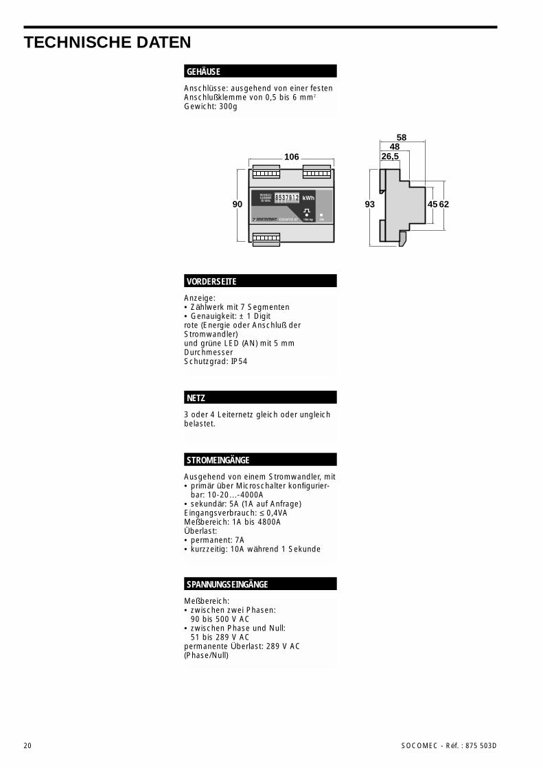
Anschlüsse: ausgehend von einer festenAnschlußklemme von 0,5 bis 6 mm2
Gewicht: 300g
GEHÄUSE
3 oder 4 Leiternetz gleich oder ungleichbelastet.
NETZ
Anzeige:• Zählwerk mit 7 Segmenten• Genauigkeit: ± 1 Digitrote (Energie oder Anschluß derStromwandler)und grüne LED (AN) mit 5 mmDurchmesserSchutzgrad: IP54
VORDERSEITE
Meßbereich:• zwischen zwei Phasen:
90 bis 500 V AC• zwischen Phase und Null:
51 bis 289 V ACpermanente Überlast: 289 V AC(Phase/Null)
SPANNUNGSEINGÄNGE
Ausgehend von einem Stromwandler, mit• primär über Microschalter konfigurier-
bar: 10-20…-4000A• sekundär: 5A (1A auf Anfrage)Eingangsverbrauch: ≤ 0,4VAMeßbereich: 1A bis 4800AÜberlast:• permanent: 7A• kurzzeitig: 10A während 1 Sekunde
STROMEINGÄNGE
106 26,548
58
90 93 45 62COUNTIS AT
DEUT
SCH
SOCOMEC - Réf. : 875 503D 21
TECHNISCHE DATEN (Fortsetzung)
Wirkenergie: IEC 1036 Klasse 1 für ATiund Klasse 2 für AT
GENAUIGKEIT
230 V oder 400 V AC, 50/60 HzToleranz: ±15%Verbrauch: 4 VA
HILFSSPANNUNG
Reedrelais 1T (100 VDC - 0,5 A - 10 VA)Impulsdauer: 100 msSchaltspielanzahl: 100 x 106 minimumEinheit pro Impuls durch Microschalterprogrammierbar: 100 Wh / 1 kWh / 10 kWh / 100 kWh2ter Impulsausgang (optional):• parallelgeschaltet zum ersten• unabhängig zum ersten (auf Anfrage)
IMPULSAUSGANG
Hilfsspannung: 2,5 KV AC während 1 MinuteStromeingang: 2,5 KV AC während 1 MinuteImpulsausgang: 2,5 KV AC während 1 Minute
GALVANISCHE TRENNUNG
Relativ zur Genauigkeit der Wirkenergie:• IEC 1036 in Klasse 1 für ATi und Klasse
2 für ATRelativ zur CE-Markierung:• EN 50081-2• EN 50082-2• IEC 1000-4-2/3-4-5-6-8-11Relativ zur Betriebsbedingung• IEC 68-2-11/30
NORMEN
Betriebstemperatur: -10°C bis +60°CLagerungtemperatur : -20°C bis +70°CFeuchtigkeit: 95%
ANWENDUNGSKONDITIONEN
22 SOCOMEC - Réf. : 875 503D
ALGEMENE INFORMATIEHet COUNTIS systeem bestaat uitproducten voor vermogensmeting voorBT elektriciteitsnetten met 3 of 4 draden.Dit systeem bestaat uit 2 producten:• De AT: meter van niet geïsoleerd
Actief Driefase vermogen zondermogelijkheid tot het aarden van detweede TC.
• De ATi: meter van geïsoleerd ActiefDriefase vermogen met mogelijkheidtot het aarden van de tweede TC.
Deze producten zijn volledig configureer-baar (TC-verhouding, netwerktype enwaarde van de impulsuitgang) en biedende mogelijkheid de kWh-consumptiedirect in 7 digits zichtbaar te maken. Ze zijn standaard uitgerust met eenimpulsuitgang (optioneel 2).
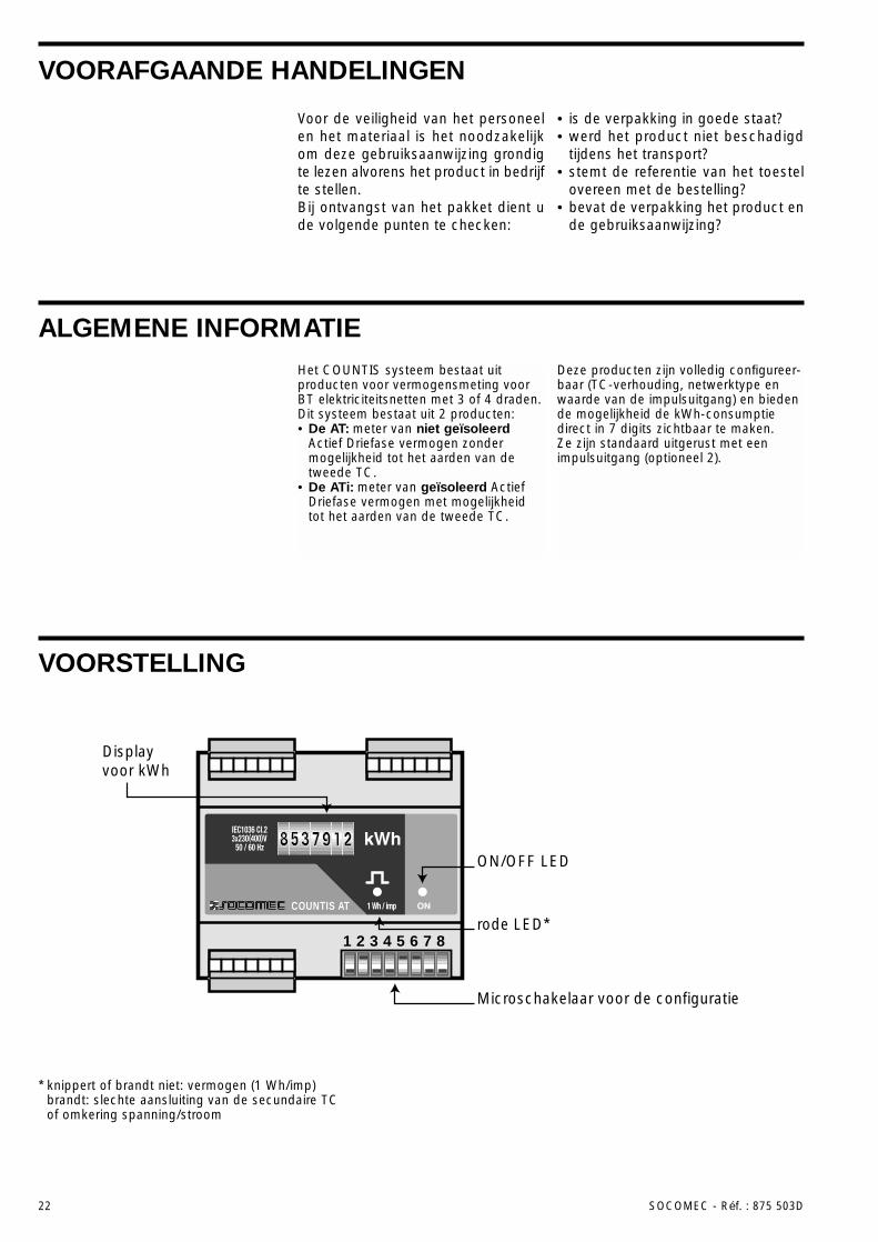
VOORSTELLING
Microschakelaar voor de configuratie
Displayvoor kWh
ON/OFF LED
rode LED*COUNTIS AT
1 2 3 4 5 6 7 8
* knippert of brandt niet: vermogen (1 Wh/imp)brandt: slechte aansluiting van de secundaire TC of omkering spanning/stroom
Voor de veiligheid van het personeelen het materiaal is het noodzakelijkom deze gebruiksaanwijzing grondigte lezen alvorens het product in bedrijfte stellen.Bij ontvangst van het pakket dient ude volgende punten te checken:
• is de verpakking in goede staat?• werd het product niet beschadigd
tijdens het transport?• stemt de referentie van het toestel
overeen met de bestelling?• bevat de verpakking het product en
de gebruiksaanwijzing?
VOORAFGAANDE HANDELINGEN
NEDE
RLAN
DS
SOCOMEC - Réf. : 875 503D 23
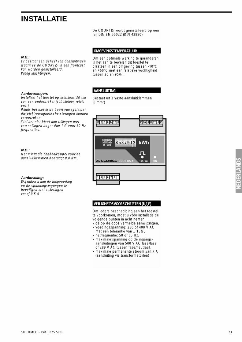
INSTALLATIEDe COUNTIS wordt geïnstalleerd op eenrail DIN EN 50022 (DIN 43880)
Om iedere beschadiging aan het toestelte voorkomen, moet u vòòr installatie devolgende punten in acht nemen:• de op de doos vermelde aanwijzingen,• voedingsspanning: 230 of 400 V AC
met een tolerantie van ± 15%,• netfrequentie: 50 of 60 Hz,• maximale spanning op de ingangs-
aansluitingen van 500 V AC fase/faseof 289 V AC tussen fase/neutraal,
• maximale permanente stroom van 7 A(aansluiting via transformator(en)
VEILIGHEIDSVOORSCHRIFTEN (U,I,F)
N.B.:Er bestaat een geheel van aansluitingenwaarmee de COUNTIS in een frontkastkan worden geïnstalleerd. Vraag inlichtingen.
N.B.:Het minimale aanhaalkoppel voor deaansluitklemmen bedraagt 0,8 Nm.
Aanbeveling:Wij raden u aan de hulpvoeding en de spanningsingangen tebeveiligen met zekeringenvanaf 0,5 A
Aanbevelingen:Installeer het toestel op minstens 30 cmvan een onderbreker (schakelaar, relaisenz.).Plaats het niet in de buurt van systemendie elektromagnetische storingen kunnenveroorzaken.Stel het niet bloot aan trillingen metversnellingen hoger dan 1 G voor 60 Hzfrequenties.
Om een optimale werking te garanderenis het aan te bevelen dit toestel teplaatsen in een omgeving tussen -10°Cen +60°C met een relatieve vochtigheidtussen 20 en 95%.
OMGEVINGSTEMPERATUUR
Bestaat uit 3 vaste aansluitklemmen(6 mm2)
AANSLUITING
COUNTIS AT
16 15171819202112 131485211
976431
24 SOCOMEC - Réf. : 875 503D
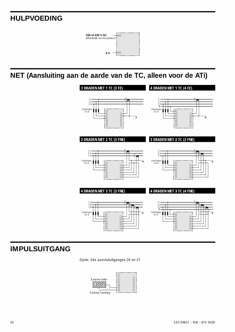
HULPVOEDING
NET (Aansluiting aan de aarde van de TC, alleen voor de ATi)
IMPULSUITGANG
L1L2L3
P1S1
P1S1
P1S1
11
2
5
8
14
12
13
1
3
4
6
7
9
Zekeringen0,5 A
L1L2L3
P1S1
P1S1
11
2
5
8
14
12
13
1
3
4
6
7
9
Zekeringen0,5 A
11
14
12
13
4
6
7
9
L1L2L3
P1S1
2
5
8
1
3
Zekeringen0,5 A
L1L2L3
P1S1
P1S1
11
2
5
8
14
12
13
1
3
4
6
7
9
Zekeringen0,5 A
L1L2L3N
Zekeringen0,5 A
P1S1
P1S1
P1S1
11
2
5
8
14
12
13
1
3
4
6
7
9
L1L2L3N
P1S1
11
2
5
8
14
12
13
1
3
4
6
7
9
Zekeringen0,5 A
Externe teller
11
2
5
8
14
12
13
1
3
4
6
7
9
Externe voeding
230 of 430 V AC(afhankelijk van het product)
0 V
15
17
3 DRADEN MET 1 TC (3 FE) 4 DRADEN MET 1 TC (4 FE)
3 DRADEN MET 2 TC (3 FNE) 3 DRADEN MET 2 TC (3 FNE)
4 DRADEN MET 3 TC (3 FNE) 4 DRADEN MET 3 TC (4 FNE)
Optie: 2de aansluituitgangen 20 en 21
NEDE
RLAN
DS
SOCOMEC - Réf. : 875 503D 25
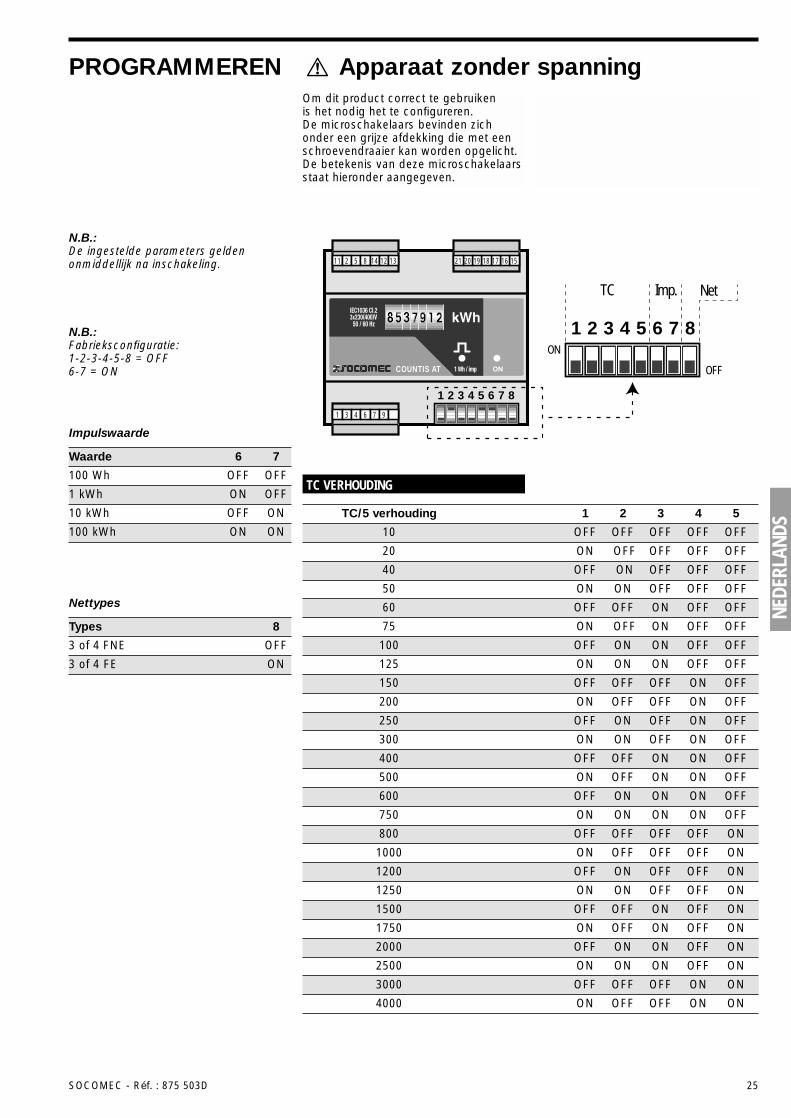
PROGRAMMEREN Apparaat zonder spanningOm dit product correct te gebruiken is het nodig het te configureren. De microschakelaars bevinden zichonder een grijze afdekking die met eenschroevendraaier kan worden opgelicht.De betekenis van deze microschakelaarsstaat hieronder aangegeven.
1
TC Imp. Net
2 3 4 5 6 7 8ON
OFFCOUNTIS AT
16 15171819202112 131485211
976431
1 2 3 4 5 6 7 8
TC VERHOUDING
10 OFF OFF OFF OFF OFF
40 OFF ON OFF OFF OFF
TC/5 verhouding 1 2 3 4 5
20 ON OFF OFF OFF OFF
50 ON ON OFF OFF OFF
60 OFF OFF ON OFF OFF
75 ON OFF ON OFF OFF
100 OFF ON ON OFF OFF
125 ON ON ON OFF OFF
200 ON OFF OFF ON OFF
300 ON ON OFF ON OFF
500 ON OFF ON ON OFF
750 ON ON ON ON OFF
1000 ON OFF OFF OFF ON
1250 ON ON OFF OFF ON
1750 ON OFF ON OFF ON
2500 ON ON ON OFF ON
4000 ON OFF OFF ON ON
150 OFF OFF OFF ON OFF
250 OFF ON OFF ON OFF
400 OFF OFF ON ON OFF
600 OFF ON ON ON OFF
800 OFF OFF OFF OFF ON
1200 OFF ON OFF OFF ON
1500 OFF OFF ON OFF ON
2000 OFF ON ON OFF ON
3000 OFF OFF OFF ON ON
N.B.:De ingestelde parameters geldenonmiddellijk na inschakeling.
N.B.:Fabrieksconfiguratie:1-2-3-4-5-8 = OFF6-7 = ON
Impulswaarde
100 Wh OFF OFF
1 kWh ON OFF
Waarde 6 7
10 kWh OFF ON
100 kWh ON ON
Nettypes
3 of 4 FNE OFF
3 of 4 FE ON
Types 8
26 SOCOMEC - Réf. : 875 503D
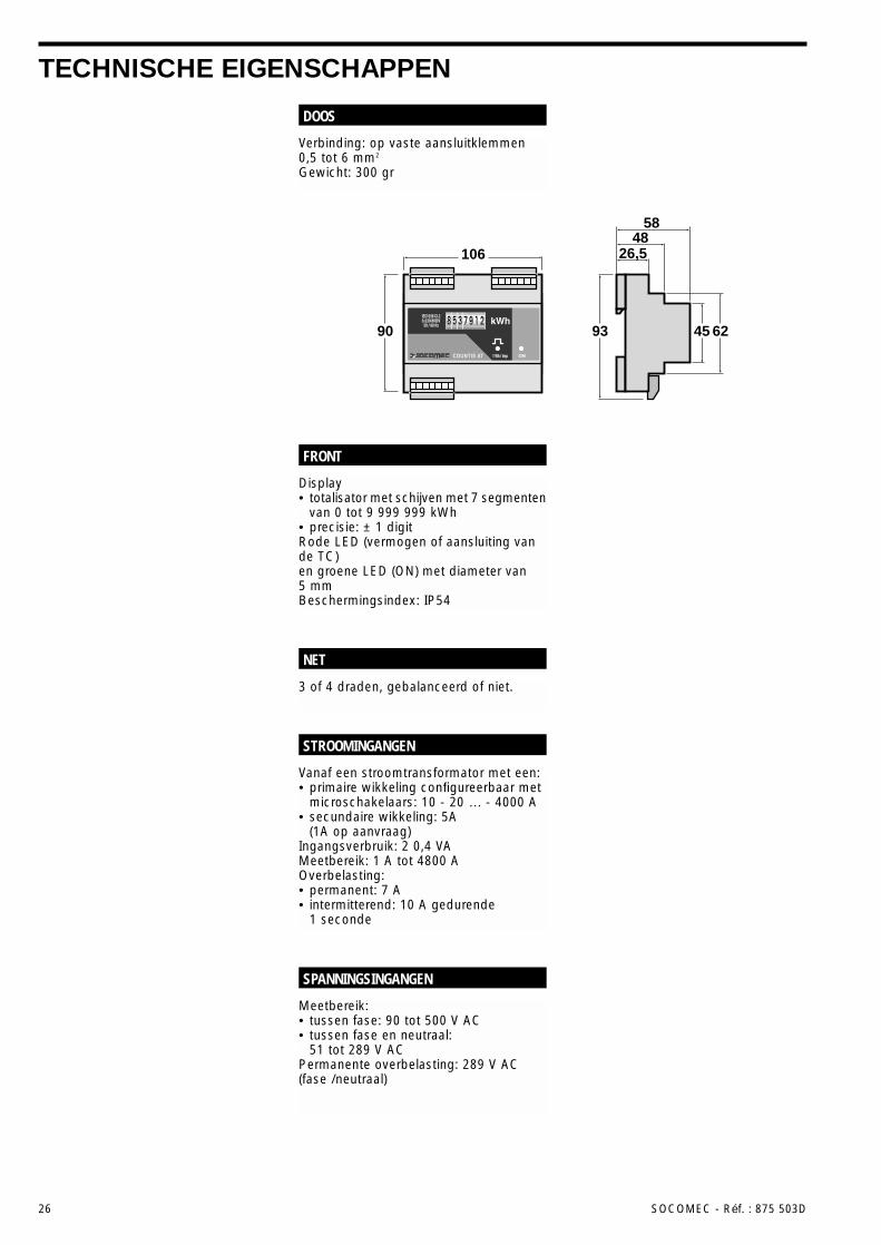
TECHNISCHE EIGENSCHAPPEN
Verbinding: op vaste aansluitklemmen0,5 tot 6 mm2
Gewicht: 300 gr
DOOS
3 of 4 draden, gebalanceerd of niet.
NET
Display• totalisator met schijven met 7 segmenten
van 0 tot 9 999 999 kWh• precisie: ± 1 digitRode LED (vermogen of aansluiting vande TC)en groene LED (ON) met diameter van5 mmBeschermingsindex: IP54
FRONT
Meetbereik:• tussen fase: 90 tot 500 V AC• tussen fase en neutraal:
51 tot 289 V ACPermanente overbelasting: 289 V AC(fase /neutraal)
SPANNINGSINGANGEN
Vanaf een stroomtransformator met een:• primaire wikkeling configureerbaar met
microschakelaars: 10 - 20 … - 4000 A• secundaire wikkeling: 5A
(1A op aanvraag)Ingangsverbruik: 2 0,4 VAMeetbereik: 1 A tot 4800 AOverbelasting:• permanent: 7 A• intermitterend: 10 A gedurende
1 seconde
STROOMINGANGEN
106 26,548
58
90 93 45 62COUNTIS AT
NEDE
RLAN
DS
SOCOMEC - Réf. : 875 503D 27
TECHNISCHE EIGENSCHAPPEN
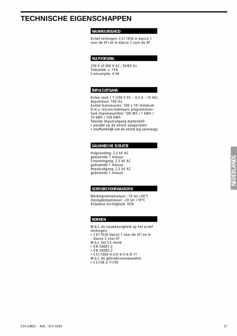
Actief vermogen: CEI 1036 in klasse 1voor de ATi en in klasse 2 voor de AT
NAUWKEURIGHEID
230 V of 400 V AC, 50/60 HzTolerantie: ± 15%Consumptie: 4 VA
HULPVOEDING
Relais reed 1 T (100 V DC - 0,5 A - 10 VA)Impulsduur: 100 msAantal manoeuvres: 100 x 106 minimumD.m.v. microschakelaars programmeer-bare impulswaarden: 100 Wh / 1 kWh /10 kWh / 100 kWhTweede impulsuitgang (optioneel)• parallel op de eerste aangesloten• onafhankelijk van de eerste (op aanvraag)
IMPULSUITGANG
Hulpvoeding: 2,5 kV AC gedurende 1 minuutStroomingang: 2,5 kV AC gedurende 1 minuutImpulsuitgang: 2,5 kV AC gedurende 1 minuut
GALVANISCHE ISOLATIE
M.b.t. de nauwkeurigheid op het actiefvermogen:• CEI 1036 klasse 1 voor de ATi en in
klasse 2 voor ATM.b.t. het CE-merk:• EN 50081-2• EN 50082-2• CEI 1000-4-2/3-4-5-6-8-11M.b.t. de gebruiksvoorwaarden:• CEI 68-2-11/30
NORMEN
Werkingstemperatuur: -10 tot +60°COpslagtemperatuur: -20 tot +70°CRelatieve vochtigheid: 95%
GEBRUIKSVOORWAARDEN
28 SOCOMEC - Réf. : 875 503D
INFORMAZIONI GENERALIIl sistema Countis é composto da variapparecchi per il conteggio dell’energiadi reti elettriche BT 3 o 4 fili, equilibrate onon equilibrate. Ê un sistema compostoda 2 prodotti:• L’AT: contatore di energia attiva trifase
non isolato che non consente il rac-cordo alla terra del secondario fra i TA.
• L’ATi: contatore di energia attiva trifaseisolato che consente il raccordo allaterra del secondario fra i TA.
Questi prodotti sono totalmente configu-rabili (portata del TA, tipo di rete e pesodell’uscita impulsi) e permettono, apartire da un visualizzatore a 7 digit, diverificare direttamente i consumi in KWh.Gli apparecchi sono forniti in formatostandard di un’uscita impulsi (2 in opzione).
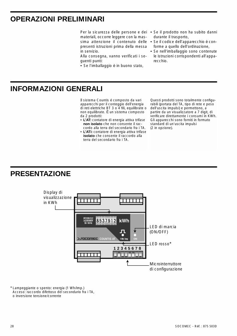
PRESENTAZIONE
Microinterruttore di configurazione
Display di visualizzazione in KWh
LED di marcia (ON/OFF)
LED rosso*COUNTIS AT
1 2 3 4 5 6 7 8
* Lampeggiante o spento: energia (1 Wh/imp.)Acceso: raccordo difettoso del secondario fra i TA, o inversione tensione/corrente
Per la sicurezza delle persone e deimateriali, occorre leggere con la mas-sima attenzione il contenuto dellepresenti istruzioni prima della messain servizio.Alla consegna, vanno verificati i se-guenti punti:• Se l’imballaggio è in buono stato,
• Se il prodotto non ha subito dannidurante il trasporto,
• Se il codice dell’apparecchio è con-forme a quello dell’ordinazione,
• Se nell’imballaggio sono contenutele istruzioni corrispondenti all’appa-recchio.
OPERAZIONI PRELIMINARI
ITAL
IANO
SOCOMEC - Réf. : 875 503D 29
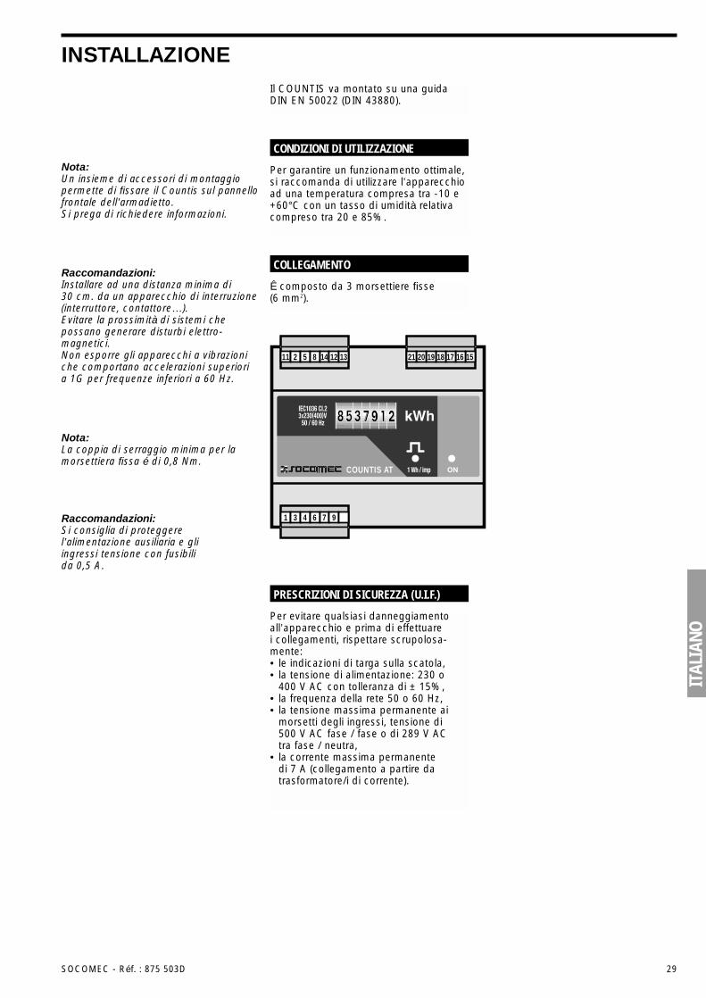
INSTALLAZIONEIl COUNTIS va montato su una guidaDIN EN 50022 (DIN 43880).
Per evitare qualsiasi danneggiamentoall’apparecchio e prima di effettuarei collegamenti, rispettare scrupolosa-mente:• le indicazioni di targa sulla scatola,• la tensione di alimentazione: 230 o
400 V AC con tolleranza di ± 15%,• la frequenza della rete 50 o 60 Hz,• la tensione massima permanente ai
morsetti degli ingressi, tensione di500 V AC fase / fase o di 289 V ACtra fase / neutra,
• la corrente massima permanente di 7 A (collegamento a partire datrasformatore/i di corrente).
PRESCRIZIONI DI SICUREZZA (U.I.F.)
Nota:Un insieme di accessori di montaggiopermette di fissare il Countis sul pannellofrontale dell’armadietto.Si prega di richiedere informazioni.
Nota:La coppia di serraggio minima per lamorsettiera fissa é di 0,8 Nm.
Raccomandazioni:Si consiglia di proteggerel’alimentazione ausiliaria e gliingressi tensione con fusibilida 0,5 A.
Raccomandazioni:Installare ad una distanza minima di30 cm. da un apparecchio di interruzione(interruttore, contattore…).Evitare la prossimità di sistemi chepossano generare disturbi elettro-magnetici.Non esporre gli apparecchi a vibrazioniche comportano accelerazioni superioria 1G per frequenze inferiori a 60 Hz.
Per garantire un funzionamento ottimale,si raccomanda di utilizzare l’apparecchioad una temperatura compresa tra -10 e+60°C con un tasso di umidità relativacompreso tra 20 e 85%.
CONDIZIONI DI UTILIZZAZIONE
Ê composto da 3 morsettiere fisse (6 mm2).
COLLEGAMENTO
COUNTIS AT
16 15171819202112 131485211
976431
30 SOCOMEC - Réf. : 875 503D
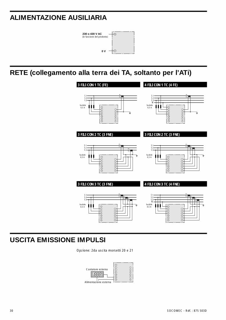
ALIMENTAZIONE AUSILIARIA
RETE (collegamento alla terra dei TA, soltanto per l’ATi)
USCITA EMISSIONE IMPULSI
L1L2L3
P1S1
P1S1
P1S1
11
2
5
8
14
12
13
1
3
4
6
7
9
fusibile0,5 A
L1L2L3
P1S1
P1S1
11
2
5
8
14
12
13
1
3
4
6
7
9
fusibile0,5 A
11
14
12
13
4
6
7
9
L1L2L3
P1S1
2
5
8
1
3
fusibile0,5 A
L1L2L3
P1S1
P1S1
11
2
5
8
14
12
13
1
3
4
6
7
9
fusibile0,5 A
L1L2L3N
fusibile0,5 A
P1S1
P1S1
P1S1
11
2
5
8
14
12
13
1
3
4
6
7
9
L1L2L3N
P1S1
11
2
5
8
14
12
13
1
3
4
6
7
9
fusibile0,5 A
Contatore esterno
11
2
5
8
14
12
13
1
3
4
6
7
9
Alimentazione esterna
230 o 430 V AC(in funzione del prodotto)
0 V
15
17
3 FILI CON 1 TC (FE) 4 FILI CON 1 TC (4 FE)
3 FILI CON 2 TC (3 FNE) 3 FILI CON 2 TC (3 FNE)
3 FILI CON 3 TC (3 FNE) 4 FILI CON 3 TC (4 FNE)
Opzione: 2da uscita morsetti 20 e 21
10 OFF OFF OFF OFF OFF
ITAL
IANO
SOCOMEC - Réf. : 875 503D 31
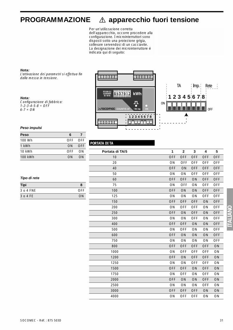
PROGRAMMAZIONE apparecchio fuori tensionePer un’utilizzazione correttadell’apparecchio, occorre procedere allaconfigurazione. I microinterruttori sonodisposti sotto una protezione grigia,sollevare servendosi di un cacciavite. La designazione dei microinterruttore éindicata qui di seguito:
1
TA Imp. Rete
2 3 4 5 6 7 8ON
OFFCOUNTIS AT
16 15171819202112 131485211
976431
1 2 3 4 5 6 7 8
PORTATA DI TA
Portata di TA/5 1 2 3 4 5
Nota:L’attivazione dei parametri si effettua findalla messa in tensione.
Nota:Configurazione di fabbrica:1-2-3-4-5-8 = OFF6-7 = ON
Peso impulsi
100 Wh OFF OFF
1 kWh ON OFF
Peso 6 7
10 kWh OFF ON
100 kWh ON ON
Tipo di rete
3 o 4 FNE OFF
3 o 4 FE ON
Tipi 8
40 OFF ON OFF OFF OFF
20 ON OFF OFF OFF OFF
50 ON ON OFF OFF OFF
60 OFF OFF ON OFF OFF
75 ON OFF ON OFF OFF
100 OFF ON ON OFF OFF
125 ON ON ON OFF OFF
200 ON OFF OFF ON OFF
300 ON ON OFF ON OFF
500 ON OFF ON ON OFF
750 ON ON ON ON OFF
1000 ON OFF OFF OFF ON
1250 ON ON OFF OFF ON
1750 ON OFF ON OFF ON
2500 ON ON ON OFF ON
4000 ON OFF OFF ON ON
150 OFF OFF OFF ON OFF
250 OFF ON OFF ON OFF
400 OFF OFF ON ON OFF
600 OFF ON ON ON OFF
800 OFF OFF OFF OFF ON
1200 OFF ON OFF OFF ON
1500 OFF OFF ON OFF ON
2000 OFF ON ON OFF ON
3000 OFF OFF OFF ON ON
32 SOCOMEC - Réf. : 875 503D
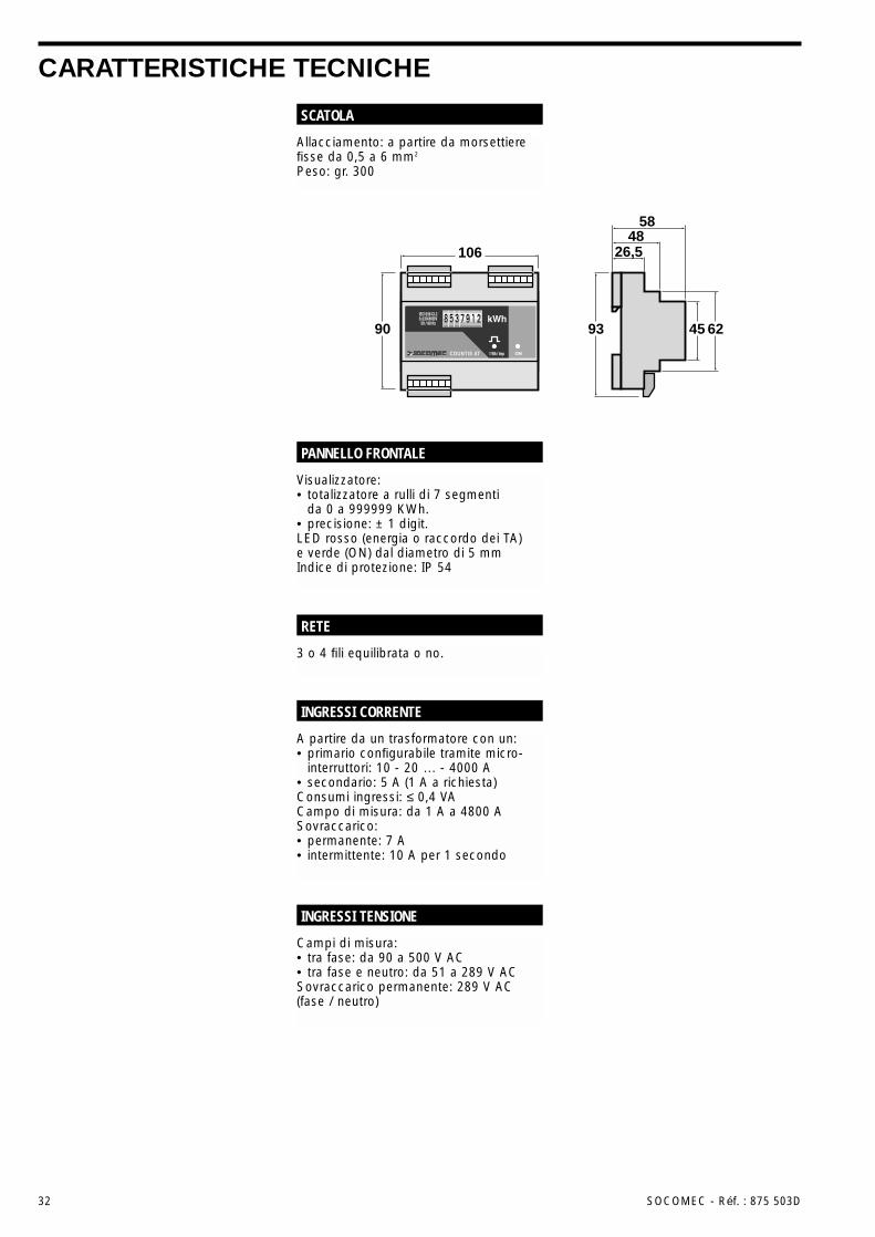
CARATTERISTICHE TECNICHE
Allacciamento: a partire da morsettierefisse da 0,5 a 6 mm2
Peso: gr. 300
SCATOLA
3 o 4 fili equilibrata o no.
RETE
Visualizzatore:• totalizzatore a rulli di 7 segmenti
da 0 a 999999 KWh.• precisione: ± 1 digit.LED rosso (energia o raccordo dei TA)e verde (ON) dal diametro di 5 mmIndice di protezione: IP 54
PANNELLO FRONTALE
Campi di misura:• tra fase: da 90 a 500 V AC• tra fase e neutro: da 51 a 289 V ACSovraccarico permanente: 289 V AC(fase / neutro)
INGRESSI TENSIONE
A partire da un trasformatore con un:• primario configurabile tramite micro-
interruttori: 10 - 20 … - 4000 A• secondario: 5 A (1 A a richiesta)Consumi ingressi: ≤ 0,4 VACampo di misura: da 1 A a 4800 ASovraccarico:• permanente: 7 A• intermittente: 10 A per 1 secondo
INGRESSI CORRENTE
106 26,548
58
90 93 45 62COUNTIS AT
ITAL
IANO
SOCOMEC - Réf. : 875 503D 33SOCOMEC - Réf. : 875 503D 33
CARATTERISTICHE TECNICHE
Energia attiva: IEC 1036 in classe 1 perl’ATi e in classe 2 per l’AT.
PRECISIONE
230 V o 400 AC, 50 / 60 HzTolleranza: ± 15%Consumi: 4 VA
ALIMENTAZIONE AUSILIARIA
Relé Reed 1 T (100 V DC - 0,5 A - 10 VA)Durata impulsi: 100 msNumero di manovre: 100 X 106 minimoPeso impulsi programmabile tramitemicrointerruttori: 100 Wh / 1 KWh /10 KWh / 100 KWhSeconda uscita impulsi (opzione):• collegata in parallelo sulla prima• indipendente dalla prima (a richiesta)
USCITA IMPULSI
Alimentazione ausiliaria: 2,5 KV AC per 1 minutoIngressi corrente: 2,5 KV AC per 1 minutoUscita impulsi: 2,5 KV AC per 1 minuto
ISOLAMENTO GALVANICO
Relativa alla precisione sull’energiaattiva:• IEC 1036 in classe 1 per l’ATi
e in classe 2 per l’AT.Relativa ai marchi CE:• En 50081-2• En 50082-2• IEC 1000-4-2/3-4-5-6-8-11Relativa alle condizioni di utilizzazione:• IEC 68-2-11/30
NORMA DI RIFERIMENTO
Temperatura di funzionamento: da -10°C a +60°CTemperatura di stoccaggio: da -20°C a +70°CUmidità relativa: 95%
CONDIZIONI DI UTILIZZAZIONE
34 SOCOMEC - Réf. : 875 503D
INFORMACIONES GENERALESEl sistema Countis se compone devarios productos para contar la energíaen redes eléctricas BT 3 ó 4 cablesequilibradas o no. Este sistema secompone de 2 productos:• El AT: contador de energía Activa
Trifásica no aislada que no permiteel empalme del secundario de los TCa tierra.
• El ATi: contador de energía ActivaTrifásica aislada que permite elempalme del secundario de los TCa tierra.
Estos productos son completamenteconfigurables (relación de TC, tipo dered y peso de la salida impulsiones) ypermiten, a partir de una representaciónvisual de 7 dígitos, visualizar directa-mente el consumo en kWh. Disponende manera standard de una salidaimpulsiones (2 en opción).
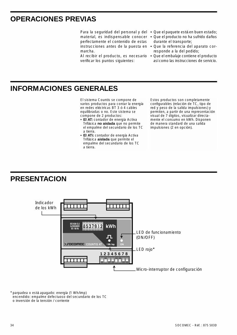
PRESENTACION
Micro-interruptor de configuración
Indicadorde los kWh
LED de funcionamiento(ON/OFF)
LED rojo*COUNTIS AT
1 2 3 4 5 6 7 8
* parpadea o está apagado: energía (1 Wh/imp)encendido: empalme defectuoso del secundario de los TCo inversión de la tensión / corriente
Para la seguridad del personal y delmaterial, es indispensable conocerperfectamente el contenido de estasinstrucciones antes de la puesta enmarcha.Al recibir el producto, es necesarioverificar los puntos siguientes:
• Que el paquete está en buen estado;• Que el producto no ha sufrido daños
durante el transporte;• Que la referencia del aparato cor-
responde a la del pedido;• Que el embalaje contiene el producto
así como las instrucciones de servicio.
OPERACIONES PREVIAS
ESPA
ÑOL
SOCOMEC - Réf. : 875 503D 35
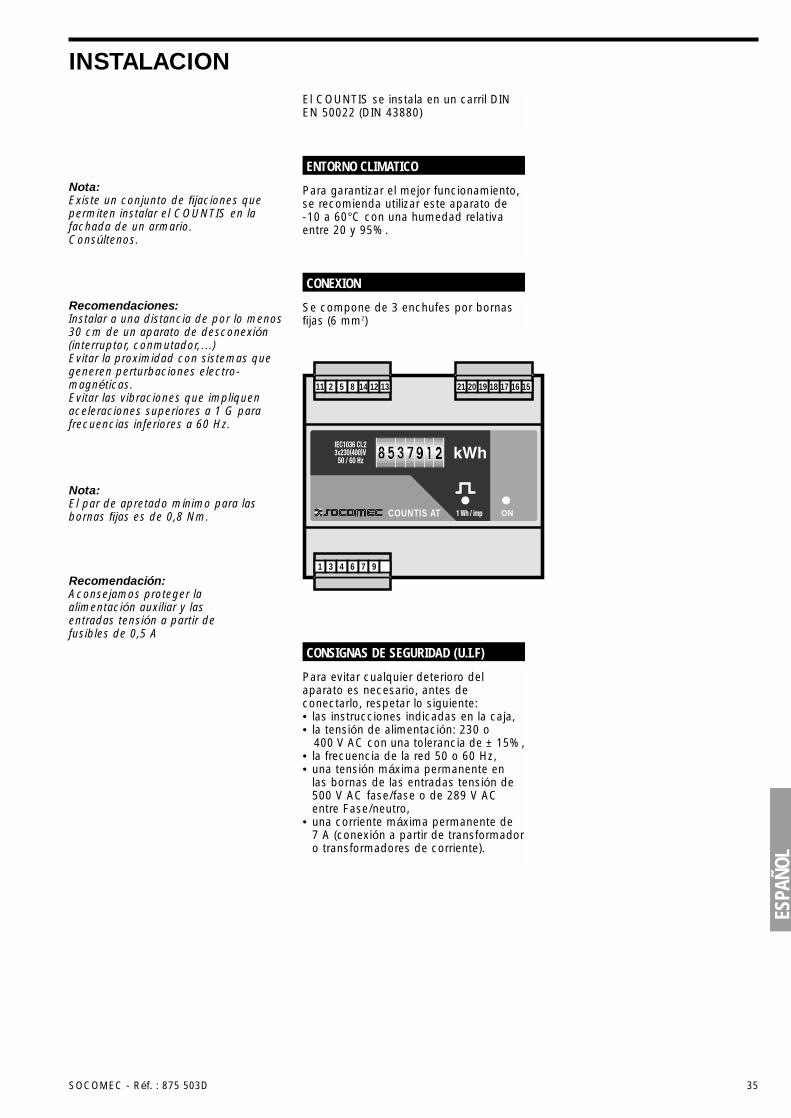
INSTALACIONEl COUNTIS se instala en un carril DINEN 50022 (DIN 43880)
Para evitar cualquier deterioro delaparato es necesario, antes deconectarlo, respetar lo siguiente:• las instrucciones indicadas en la caja,• la tensión de alimentación: 230 o
400 V AC con una tolerancia de ± 15%,• la frecuencia de la red 50 o 60 Hz,• una tensión máxima permanente en
las bornas de las entradas tensión de500 V AC fase/fase o de 289 V ACentre Fase/neutro,
• una corriente máxima permanente de7 A (conexión a partir de transformadoro transformadores de corriente).
CONSIGNAS DE SEGURIDAD (U.I.F)
Nota:Existe un conjunto de fijaciones quepermiten instalar el COUNTIS en lafachada de un armario. Consúltenos.
Nota:El par de apretado mínimo para lasbornas fijas es de 0,8 Nm.
Recomendación:Aconsejamos proteger laalimentación auxiliar y lasentradas tensión a partir defusibles de 0,5 A
Recomendaciones:Instalar a una distancia de por lo menos30 cm de un aparato de desconexión(interruptor, conmutador,…)Evitar la proximidad con sistemas quegeneren perturbaciones electro-magnéticas.Evitar las vibraciones que impliquenaceleraciones superiores a 1 G parafrecuencias inferiores a 60 Hz.
Para garantizar el mejor funcionamiento,se recomienda utilizar este aparato de -10 a 60°C con una humedad relativaentre 20 y 95%.
ENTORNO CLIMATICO
Se compone de 3 enchufes por bornasfijas (6 mm2)
CONEXION
COUNTIS AT
16 15171819202112 131485211
976431
36 SOCOMEC - Réf. : 875 503D
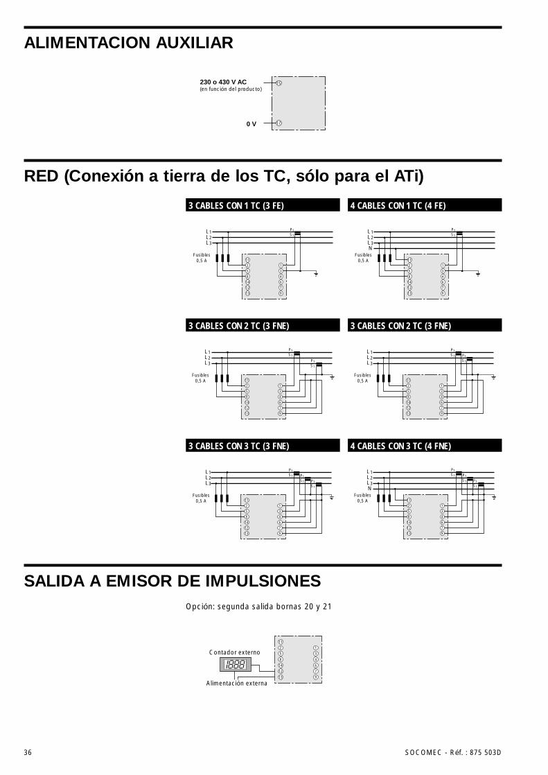
ALIMENTACION AUXILIAR
RED (Conexión a tierra de los TC, sólo para el ATi)
SALIDA A EMISOR DE IMPULSIONES
Contador externo
11
2
5
8
14
12
13
1
3
4
6
7
9
Alimentación externa
230 o 430 V AC(en función del producto)
0 V
15
17
3 CABLES CON 1 TC (3 FE) 4 CABLES CON 1 TC (4 FE)
3 CABLES CON 2 TC (3 FNE) 3 CABLES CON 2 TC (3 FNE)
3 CABLES CON 3 TC (3 FNE) 4 CABLES CON 3 TC (4 FNE)
Opción: segunda salida bornas 20 y 21
L1L2L3
P1S1
P1S1
P1S1
11
2
5
8
14
12
13
1
3
4
6
7
9
Fusibles0,5 A
L1L2L3
P1S1
P1S1
11
2
5
8
14
12
13
1
3
4
6
7
9
Fusibles0,5 A
11
14
12
13
4
6
7
9
L1L2L3
P1S1
2
5
8
1
3
Fusibles0,5 A
L1L2L3
P1S1
P1S1
11
2
5
8
14
12
13
1
3
4
6
7
9
Fusibles0,5 A
L1L2L3N
Fusibles0,5 A
P1S1
P1S1
P1S1
11
2
5
8
14
12
13
1
3
4
6
7
9
L1L2L3N
P1S1
11
2
5
8
14
12
13
1
3
4
6
7
9
Fusibles0,5 A
10 OFF OFF OFF OFF OFF
ESPA
ÑOL
SOCOMEC - Réf. : 875 503D 37
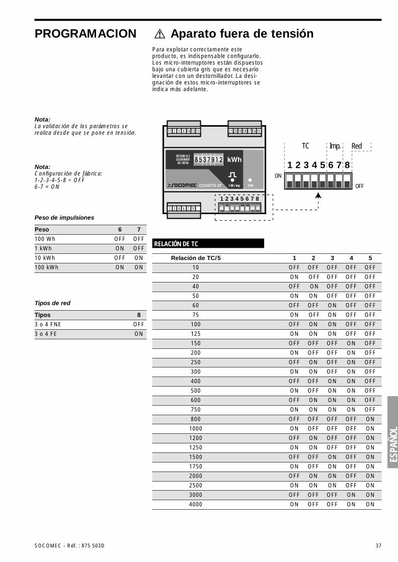
PROGRAMACION Aparato fuera de tensiónPara explotar correctamente esteproducto, es indispensable configurarlo.Los micro-interruptores están dispuestosbajo una cubierta gris que es necesariolevantar con un destornillador. La desi-gnación de estos micro-interruptores seindica más adelante.
1
TC Imp. Red
2 3 4 5 6 7 8ON
OFFCOUNTIS AT
16 15171819202112 131485211
976431
1 2 3 4 5 6 7 8
RELACIÓN DE TC
Relación de TC/5 1 2 3 4 5
Nota:La validación de los parámetros serealiza desde que se pone en tensión.
Nota:Configuración de fábrica:1-2-3-4-5-8 = OFF6-7 = ON
Peso de impulsiones
100 Wh OFF OFF
1 kWh ON OFF
Peso 6 7
10 kWh OFF ON
100 kWh ON ON
Tipos de red
3 o 4 FNE OFF
3 o 4 FE ON
Tipos 8
40 OFF ON OFF OFF OFF
20 ON OFF OFF OFF OFF
50 ON ON OFF OFF OFF
60 OFF OFF ON OFF OFF
75 ON OFF ON OFF OFF
100 OFF ON ON OFF OFF
125 ON ON ON OFF OFF
200 ON OFF OFF ON OFF
300 ON ON OFF ON OFF
500 ON OFF ON ON OFF
750 ON ON ON ON OFF
1000 ON OFF OFF OFF ON
1250 ON ON OFF OFF ON
1750 ON OFF ON OFF ON
2500 ON ON ON OFF ON
4000 ON OFF OFF ON ON
150 OFF OFF OFF ON OFF
250 OFF ON OFF ON OFF
400 OFF OFF ON ON OFF
600 OFF ON ON ON OFF
800 OFF OFF OFF OFF ON
1200 OFF ON OFF OFF ON
1500 OFF OFF ON OFF ON
2000 OFF ON ON OFF ON
3000 OFF OFF OFF ON ON
38 SOCOMEC - Réf. : 875 503D
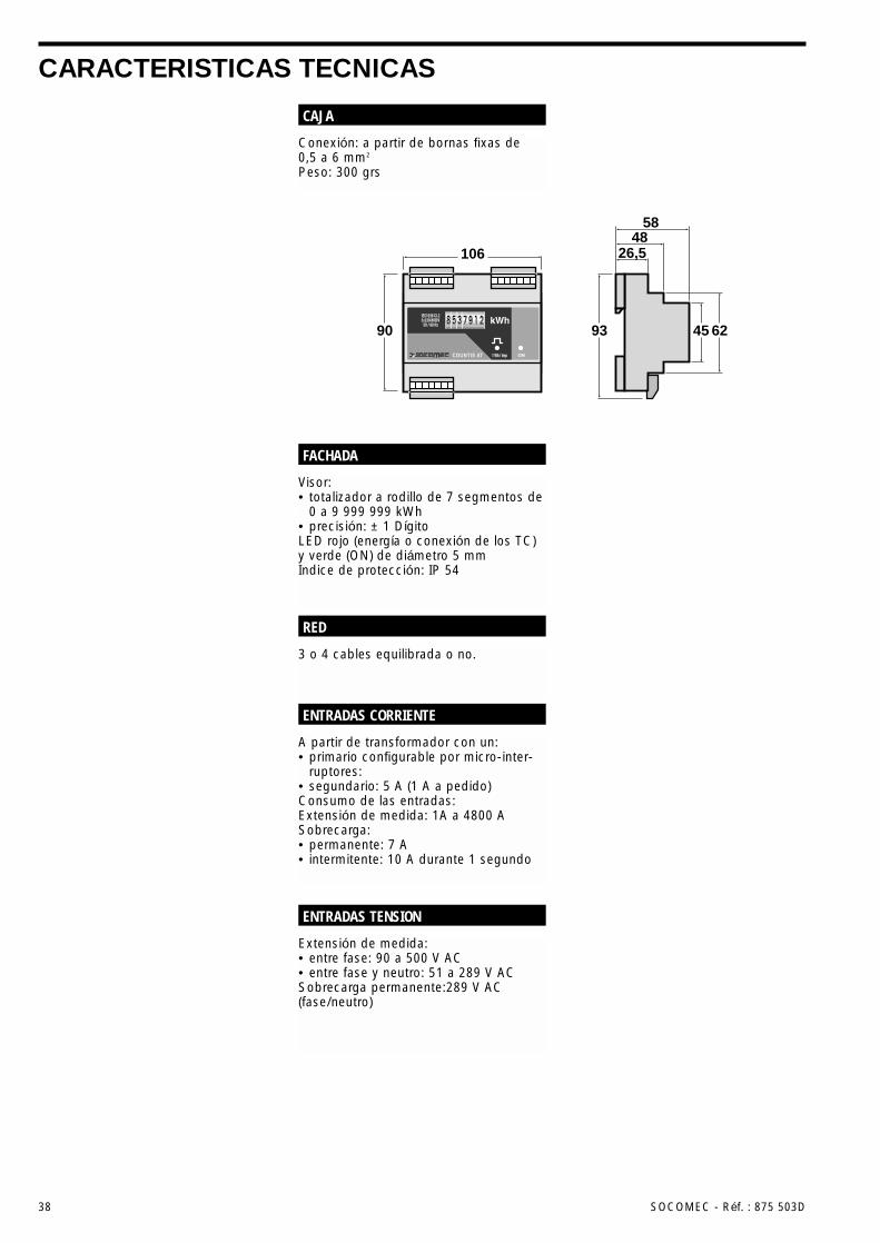
CARACTERISTICAS TECNICAS
Conexión: a partir de bornas fixas de0,5 a 6 mm2
Peso: 300 grs
CAJA
3 o 4 cables equilibrada o no.
RED
Visor:• totalizador a rodillo de 7 segmentos de
0 a 9 999 999 kWh• precisión: ± 1 DígitoLED rojo (energía o conexión de los TC)y verde (ON) de diámetro 5 mmIndice de protección: IP 54
FACHADA
Extensión de medida:• entre fase: 90 a 500 V AC• entre fase y neutro: 51 a 289 V ACSobrecarga permanente:289 V AC(fase/neutro)
ENTRADAS TENSION
A partir de transformador con un:• primario configurable por micro-inter-
ruptores:• segundario: 5 A (1 A a pedido)Consumo de las entradas:Extensión de medida: 1A a 4800 ASobrecarga:• permanente: 7 A• intermitente: 10 A durante 1 segundo
ENTRADAS CORRIENTE
106 26,548
58
90 93 45 62COUNTIS AT
ESPA
ÑOL
SOCOMEC - Réf. : 875 503D 39
CARACTERISTICAS TECNICAS
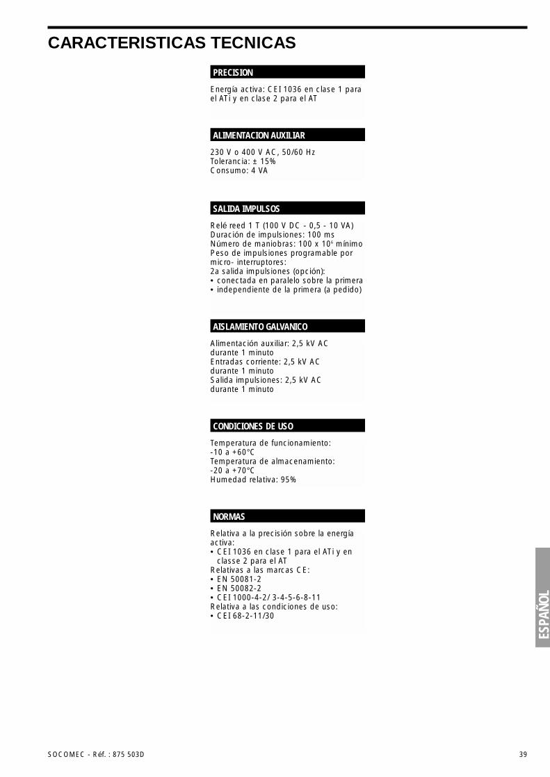
Energía activa: CEI 1036 en clase 1 parael ATi y en clase 2 para el AT
PRECISION
230 V o 400 V AC, 50/60 HzTolerancia: ± 15%Consumo: 4 VA
ALIMENTACION AUXILIAR
Relé reed 1 T (100 V DC - 0,5 - 10 VA)Duración de impulsiones: 100 msNúmero de maniobras: 100 x 106 mínimoPeso de impulsiones programable pormicro- interruptores:2a salida impulsiones (opción):• conectada en paralelo sobre la primera• independiente de la primera (a pedido)
SALIDA IMPULSOS
Alimentación auxiliar: 2,5 kV AC durante 1 minutoEntradas corriente: 2,5 kV AC durante 1 minutoSalida impulsiones: 2,5 kV AC durante 1 minuto
AISLAMIENTO GALVANICO
Relativa a la precisión sobre la energíaactiva:• CEI 1036 en clase 1 para el ATi y en
classe 2 para el ATRelativas a las marcas CE:• EN 50081-2• EN 50082-2• CEI 1000-4-2/ 3-4-5-6-8-11Relativa a las condiciones de uso:• CEI 68-2-11/30
NORMAS
Temperatura de funcionamiento: -10 a +60°CTemperatura de almacenamiento: -20 a +70°CHumedad relativa: 95%
CONDICIONES DE USO
40 SOCOMEC - Réf. : 875 503D
INFORMAÇÕES GERAISO sistema Countis compõe-se de váriosprodutos destinados à contagem daenergia para redes eléctricas BT 3 ou de4 fios equilibradas ou não. Este sistemaé composto por 2 produtos:• o AT: contador de energia Activa
Trifásica não isolado que não permitea ligação do secundário dos TC àterra;
• o ATi: contador de energia ActivaTrifásica isolado que permite a ligaçãodo secundário dos TC à terra
Estes produtos são totalmenteconfiguráveis (relação de TC, tipo derede e carga da saída dos impulsos) e permitem, através de um mostradosde 7 dígitos, visualizar directamente o consumo em kWh. Estão equipadosde origem de uma saída dos impulsos (2 em opção).
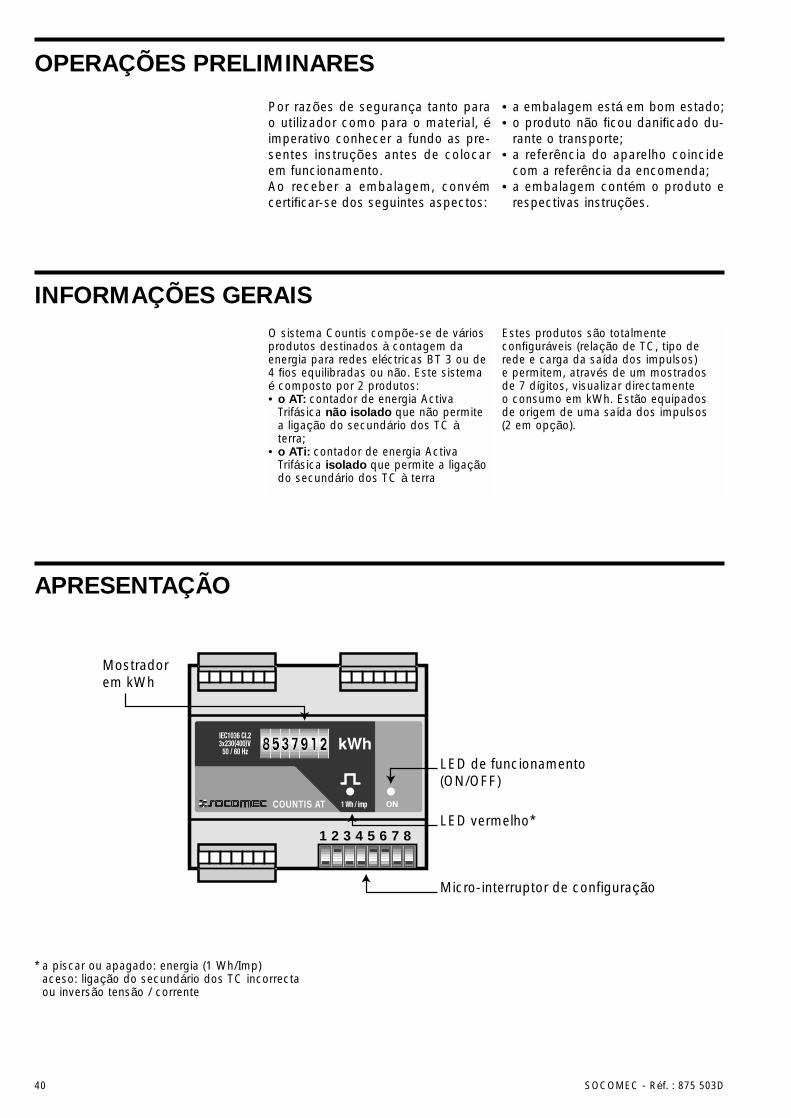
APRESENTAÇÃO
Micro-interruptor de configuração
Mostradorem kWh
LED de funcionamento(ON/OFF)
LED vermelho*COUNTIS AT
1 2 3 4 5 6 7 8
* a piscar ou apagado: energia (1 Wh/Imp)aceso: ligação do secundário dos TC incorrecta ou inversão tensão / corrente
Por razões de segurança tanto parao utilizador como para o material, éimperativo conhecer a fundo as pre-sentes instruções antes de colocarem funcionamento.Ao receber a embalagem, convémcertificar-se dos seguintes aspectos:
• a embalagem está em bom estado;• o produto não ficou danificado du-
rante o transporte;• a referência do aparelho coincide
com a referência da encomenda;• a embalagem contém o produto e
respectivas instruções.
OPERAÇÕES PRELIMINARES
PORT
UGUÊ
S
SOCOMEC - Réf. : 875 503D 41
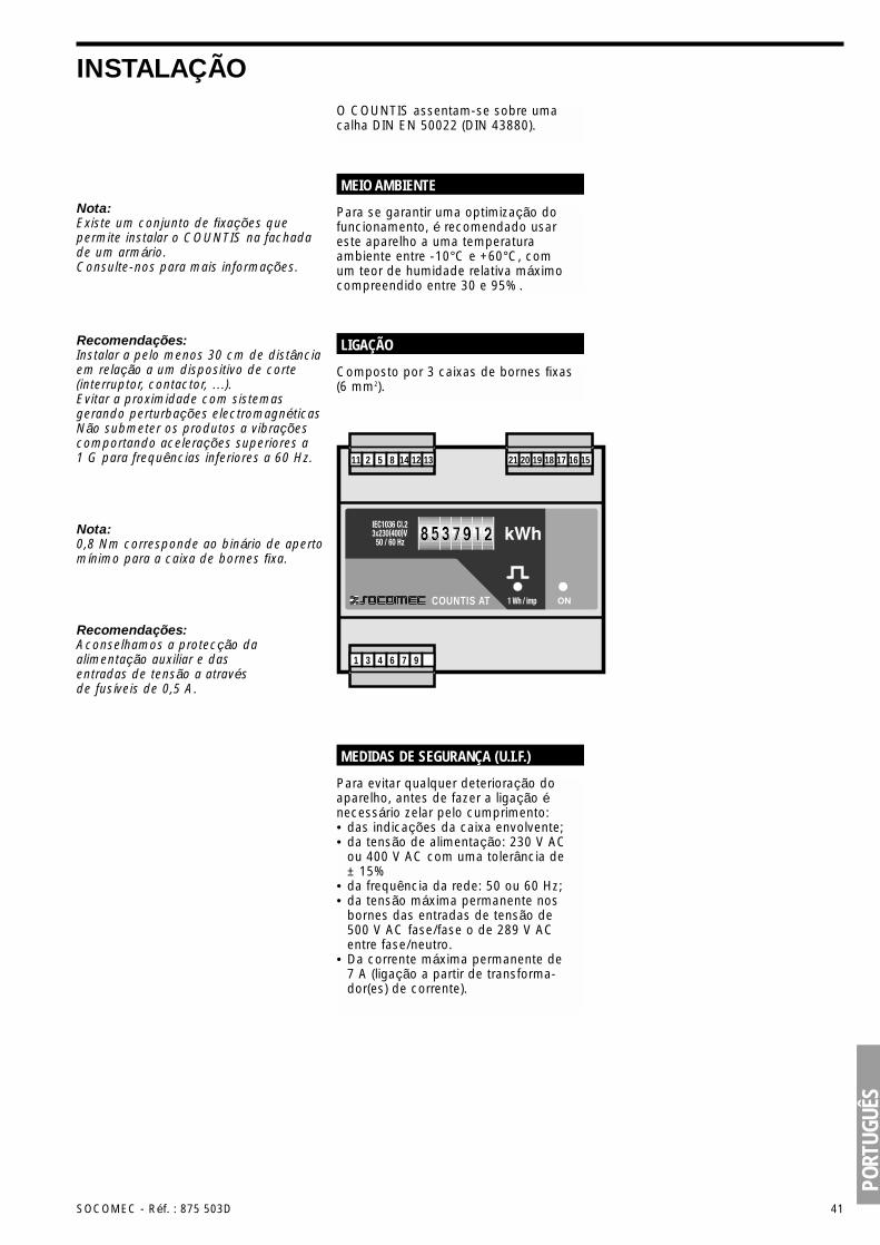
INSTALAÇÃOO COUNTIS assentam-se sobre umacalha DIN EN 50022 (DIN 43880).
Para evitar qualquer deterioração doaparelho, antes de fazer a ligação énecessário zelar pelo cumprimento:• das indicações da caixa envolvente;• da tensão de alimentação: 230 V AC
ou 400 V AC com uma tolerância de± 15%
• da frequência da rede: 50 ou 60 Hz;• da tensão máxima permanente nos
bornes das entradas de tensão de500 V AC fase/fase o de 289 V ACentre fase/neutro.
• Da corrente máxima permanente de7 A (ligação a partir de transforma-dor(es) de corrente).
MEDIDAS DE SEGURANÇA (U.I.F.)
Nota:Existe um conjunto de fixações quepermite instalar o COUNTIS na fachadade um armário.Consulte-nos para mais informações.
Nota:0,8 Nm corresponde ao binário de apertomínimo para a caixa de bornes fixa.
Recomendações:Aconselhamos a protecção daalimentação auxiliar e dasentradas de tensão a atravésde fusíveis de 0,5 A.
Recomendações:Instalar a pelo menos 30 cm de distânciaem relação a um dispositivo de corte(interruptor, contactor, …).Evitar a proximidade com sistemasgerando perturbações electromagnéticasNão submeter os produtos a vibraçõescomportando acelerações superiores a1 G para frequências inferiores a 60 Hz.
Para se garantir uma optimização dofuncionamento, é recomendado usareste aparelho a uma temperaturaambiente entre -10°C e +60°C, comum teor de humidade relativa máximocompreendido entre 30 e 95%.
MEIO AMBIENTE
Composto por 3 caixas de bornes fixas(6 mm2).
LIGAÇÃO
COUNTIS AT
16 15171819202112 131485211
976431
42 SOCOMEC - Réf. : 875 503D
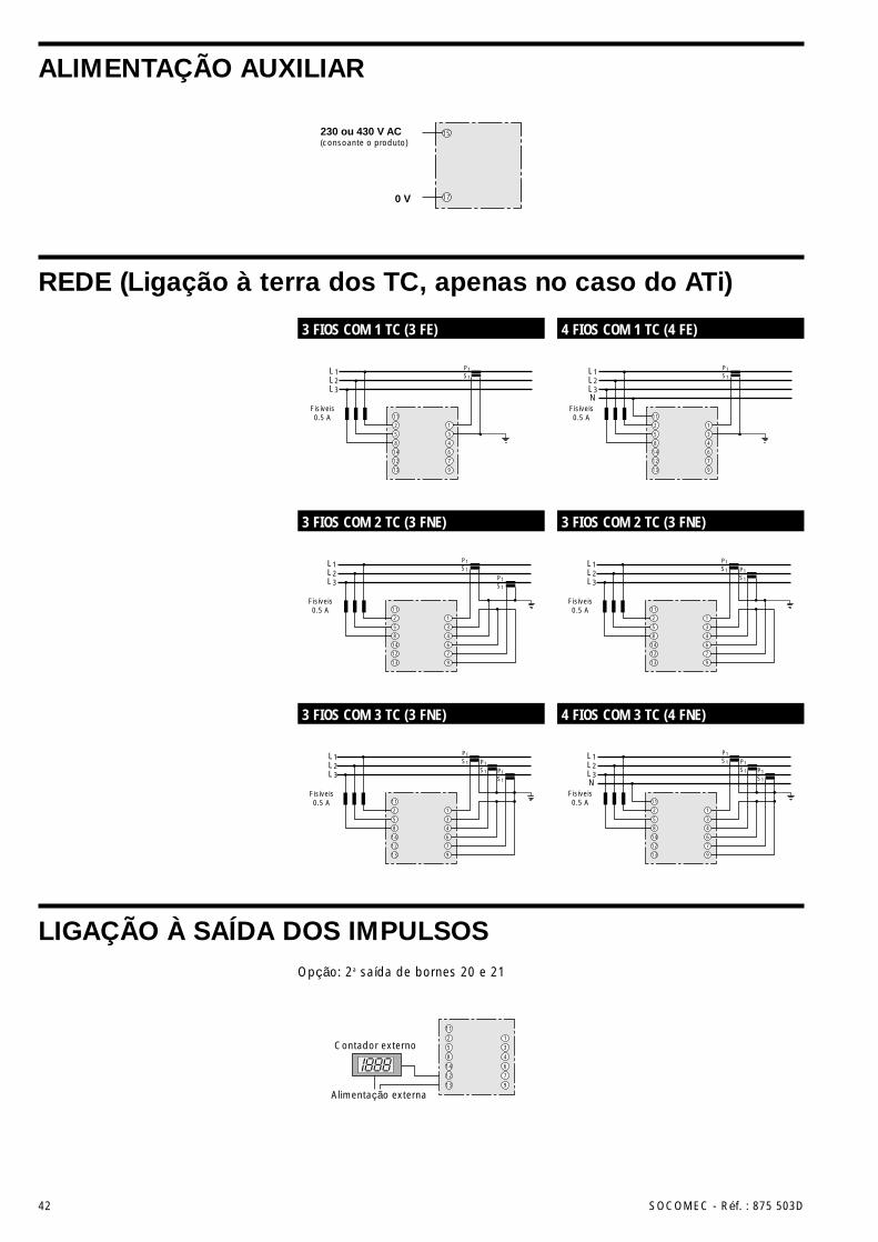
ALIMENTAÇÃO AUXILIAR
REDE (Ligação à terra dos TC, apenas no caso do ATi)
LIGAÇÃO À SAÍDA DOS IMPULSOS
L1L2L3
P1S1
P1S1
P1S1
11
2
5
8
14
12
13
1
3
4
6
7
9
Fisíveis0.5 A
L1L2L3
P1S1
P1S1
11
2
5
8
14
12
13
1
3
4
6
7
9
Fisíveis0.5 A
11
14
12
13
4
6
7
9
L1L2L3
P1S1
2
5
8
1
3
Fisíveis0.5 A
L1L2L3
P1S1
P1S1
11
2
5
8
14
12
13
1
3
4
6
7
9
Fisíveis0.5 A
L1L2L3N
Fisíveis0.5 A
P1S1
P1S1
P1S1
11
2
5
8
14
12
13
1
3
4
6
7
9
L1L2L3N
P1S1
11
2
5
8
14
12
13
1
3
4
6
7
9
Fisíveis0.5 A
Contador externo
11
2
5
8
14
12
13
1
3
4
6
7
9
Alimentação externa
230 ou 430 V AC(consoante o produto)
0 V
15
17
3 FIOS COM 1 TC (3 FE) 4 FIOS COM 1 TC (4 FE)
3 FIOS COM 2 TC (3 FNE) 3 FIOS COM 2 TC (3 FNE)
3 FIOS COM 3 TC (3 FNE) 4 FIOS COM 3 TC (4 FNE)
Opção: 2a saída de bornes 20 e 21
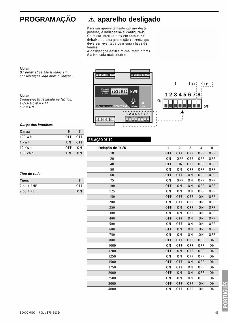
10 OFF OFF OFF OFF OFF
PORT
UGUÊ
S
SOCOMEC - Réf. : 875 503D 43
PROGRAMAÇÃO aparelho desligadoPara um aproveitamento óptimo desteproduto, é indispensável configurá-lo.Os micro-interruptores encontram-sedebaixo de uma protecção cinzenta quedeve ser levantada com uma chave defendas.A designação destes micro-interruptoresé a indicada mais abaixo.
1
TC Imp. Rede
2 3 4 5 6 7 8ON
OFFCOUNTIS AT
16 15171819202112 131485211
976431
1 2 3 4 5 6 7 8
RELAÇÃO DE TC
Relação de TC/5 1 2 3 4 5
Nota:Os parâmetros são levados emconsideração logo após a ligação.
Nota:Configuração realizada na fábrica:1-2-3-4-5-8 = OFF6-7 = ON
Carga dos impulsos
100 Wh OFF OFF
1 kWh ON OFF
Carga 6 7
10 kWh OFF ON
100 kWh ON ON
Tipo de rede
2 ou 4 FNE OFF
2 ou 4 FE ON
Tipos 8
40 OFF ON OFF OFF OFF
20 ON OFF OFF OFF OFF
50 ON ON OFF OFF OFF
60 OFF OFF ON OFF OFF
75 ON OFF ON OFF OFF
100 OFF ON ON OFF OFF
125 ON ON ON OFF OFF
200 ON OFF OFF ON OFF
300 ON ON OFF ON OFF
500 ON OFF ON ON OFF
750 ON ON ON ON OFF
1000 ON OFF OFF OFF ON
1250 ON ON OFF OFF ON
1750 ON OFF ON OFF ON
2500 ON ON ON OFF ON
4000 ON OFF OFF ON ON
150 OFF OFF OFF ON OFF
250 OFF ON OFF ON OFF
400 OFF OFF ON ON OFF
600 OFF ON ON ON OFF
800 OFF OFF OFF OFF ON
1200 OFF ON OFF OFF ON
1500 OFF OFF ON OFF ON
2000 OFF ON ON OFF ON
3000 OFF OFF OFF ON ON

44 SOCOMEC - Réf. : 875 503D
CARACTERÍSTICAS TÉCNICAS
Ligação: a partir de bornes fixos de 0,5 a 6 mm2
Peso: 300 g.
CAIXA ENVOLVENTE
3 ou 4 fios equilibrados ou não.
REDE
Mostrador• Totalizador de rolos de 7 segmentos de
0 a 9 999 999 kWh• Nível de precisão: ±1 dígitoLED vermelho (energia ou ligação dos TC)e verde (ON) de 5 mm de diâmetroÍndice de protecção: IP 54
PARTE DA FRENTE
Intervalo de medição:• entre fase: 90 a 500 V AC• entre fase e neutro: 51 a 289 V ACSobrecarga permanente: 289 V AC(fase/neutro)
ENTRADAS DE TENSÃO
A partir de um transformador com um:• primário configurável por micro-
interruptores: 10 - 20 … - 4000 A• secundário: 5 A (1 A por encomenda)Consumo das entradas: £ 0,4 VAIntervalo de medição: 1 A a 4800 ASobrecarga:• permanente: 7 A• Intermitente: 10 A durante 1 segundo
ENTRADAS DE CORRENTE
106 26,548
58
90 93 45 62COUNTIS AT
PORT
UGUÊ
S
SOCOMEC - Réf. : 875 503D 45
CARACTERÍSTICAS TÉCNICAS
Energia activa: CEI 1036 na classe 1para o ATi e na classe 2 para o AT
NÍVEL DE PRECISÃO
230 V ou 400 V AC 50 / 60 HzTolerância: ± 15%Consumo: 4 VA
ALIMENTAÇÃO AUXILIAR
Relé reed 1 T (100 V DC - 0,5 A - 10 VA)Duração dos impulsos: 100 msQuantidade de manobras: 100 x 106 mínimoCarga dos impulsos programável pormicro-interruptores: 100 Wh / 1 kWh /10 kWh / 100 kWh2a saída dos impulsos (opção):• ligada em paralelo na primeira• independente da primeira (por
encomenda)
SAÍDA DOS IMPULSOS
Alimentação auxiliar: 2,5 kV AC durante 1 minutoEntrada da corrente: 2,5 kV AC durante 1 minutoSaída dos impulsos: 2,5 kV AC durante 1 minuto
ISOLAMENTO GALVÂNICO
Relativa ao nível de precisão sobre aenergia activa:• CEI 1036 na classe 1 para o ATi e na
classe 2 para o ATRelativa à marcação CE:• EN 50081-2• EN 50082-2• CEI 1000-4-2/3-4-5-6-8-11Relativa à condições de utilização:• CEI 68-2-11/30
NORMAS
Temperatura de funcionamento: -10°C a +60°CTemperatura de armazenamento: -20°C a +70°CHumidade relativa: 95%
CONDIÇÕES DE UTILIZAÇÃO


Référence : 870 503D - 01/2000
SIEGE SOCIAL ET USINESHEAD OFFICE AND PLANTS
GROUPE SOCOMECInterrupteurs industriels et OnduleursSOCOMEC S.A.au capital de 56 207 000 F - 5 568 702 €R.C. Strasbourg 5484500 149 BBP 10 - Rue de Westhouse - F-67230 BenfeldTél. 03 88 57 41 41 - Télécopie 03 88 57 42 60
SOCOMEC118, av. du Mal de Lattre de TassignyF-94132 Fontenay-sous-Bois CedexTél. 01 45 14 63 40 - Télécopie 01 48 77 31 12
DIRECTION COMMERCIALESALES MANAGEMENT DIVISION Systèmes de Coupure et de Protection
S w i t c h i n g a n d P r o t e c t i o n S y s t e m s
Ce document n’est pas contractuel. La société SOCOMECse réserve le droit de modifier sans préavis les caractéris-tiques dans un souci permanent d’amélioration.This document is not contractual. SOCOMEC reserves theright to modify features without prior notice in view ofcontinued improvements.
CO
UN
T 31
A