Check valvesand strainers
BELGICAST is a company of

Check valves and strainers2
TALIS – the number one choice for all valve-related products.
TALIS is the major brand whenever products and services are needed for the water cycle. The brands ATLANTIC PLASTICS, BAYARD, BELGICAST, ERHARD, FRISCHHUT, SCHMIEDING, STRATE, UNIJOINT and WAFREGA are united under this name to provide a unique comprehensive service that provides the best solution for every application. Our global experience and the in-depth knowledge of our employees are the basis for TALIS’ innovative strength. In our quest for new sustainable solutions, we regularly set new milestones in valve technology. And have been doing so for more than 100 years.Our main focus is always on increasing efficiency in handling the resource water, on a long service life and economic feasibility. TALIS products meet the most stringent quality standards and are certified all over the world.
Check valves and strainers 3
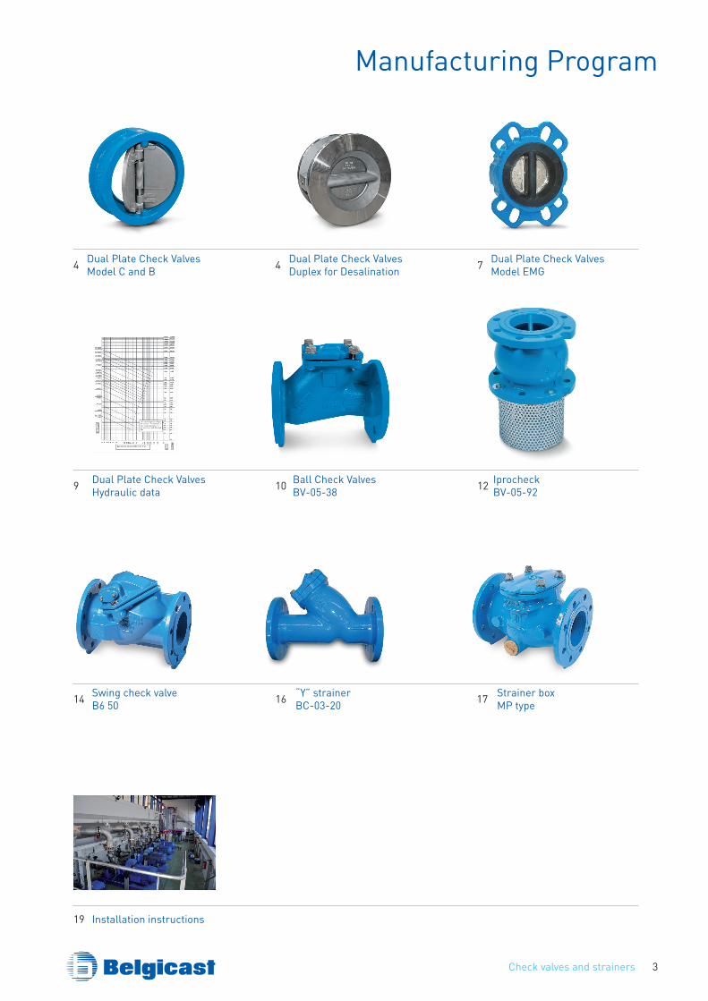
Manufacturing Program
4 Dual Plate Check ValvesModel C and B 4 Dual Plate Check Valves
Duplex for Desalination 7 Dual Plate Check ValvesModel EMG
9 Dual Plate Check ValvesHydraulic data 10 Ball Check Valves
BV-05-38 12 IprocheckBV-05-92
14 Swing check valveB6 50 16 “Y” strainer
BC-03-20 17 Strainer boxMP type
19 Installation instructions
Check valves and strainers4
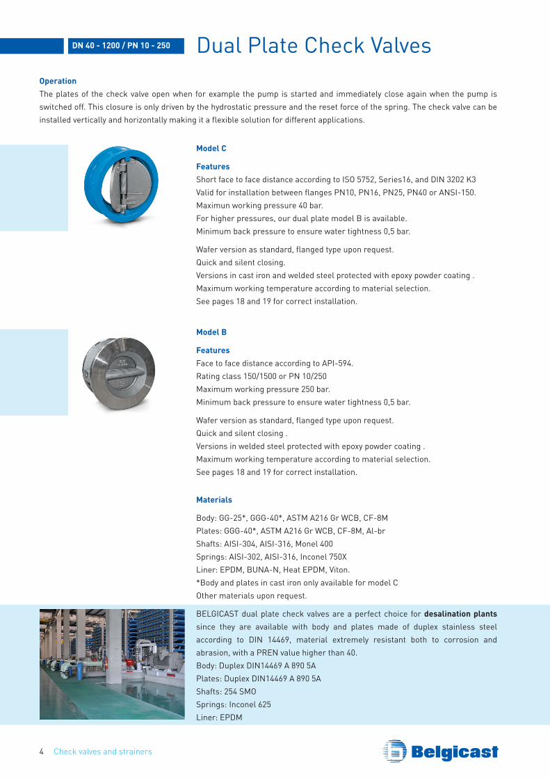
Dual Plate Check ValvesOperationThe plates of the check valve open when for example the pump is started and immediately close again when the pump is switched off. This closure is only driven by the hydrostatic pressure and the reset force of the spring. The check valve can be installed vertically and horizontally making it a flexible solution for different applications.
Model C
FeaturesShort face to face distance according to ISO 5752, Series16, and DIN 3202 K3Valid for installation between flanges PN10, PN16, PN25, PN40 or ANSI-150.Maximun working pressure 40 bar.For higher pressures, our dual plate model B is available.Minimum back pressure to ensure water tightness 0,5 bar.
Wafer version as standard, flanged type upon request.Quick and silent closing.Versions in cast iron and welded steel protected with epoxy powder coating .Maximum working temperature according to material selection.See pages 18 and 19 for correct installation.
Model B
FeaturesFace to face distance according to API-594.Rating class 150/1500 or PN 10/250Maximum working pressure 250 bar.Minimum back pressure to ensure water tightness 0,5 bar.
Wafer version as standard, flanged type upon request.Quick and silent closing .Versions in welded steel protected with epoxy powder coating .Maximum working temperature according to material selection.See pages 18 and 19 for correct installation.
Materials
Body: GG-25*, GGG-40*, ASTM A216 Gr WCB, CF-8MPlates: GGG-40*, ASTM A216 Gr WCB, CF-8M, Al-brShafts: AISI-304, AISI-316, Monel 400Springs: AISI-302, AISI-316, Inconel 750XLiner: EPDM, BUNA-N, Heat EPDM, Viton.*Body and plates in cast iron only available for model COther materials upon request.
BELGICAST dual plate check valves are a perfect choice for desalination plants since they are available with body and plates made of duplex stainless steel according to DIN 14469, material extremely resistant both to corrosion and abrasion, with a PREN value higher than 40.Body: Duplex DIN14469 A 890 5APlates: Duplex DIN14469 A 890 5AShafts: 254 SMOSprings: Inconel 625Liner: EPDM
DN 40 - 1200 / PN 10 - 250
Check valves and strainers 5
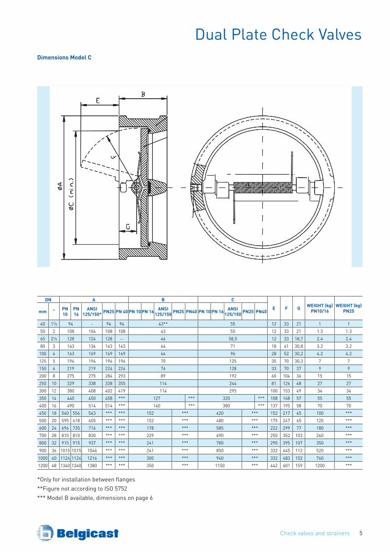
Dual Plate Check ValvesDimensions Model C
DN A B C
E F G WEIGHT (kg)PN10/16
WEIGHT (kg)PN25mm “ PN
10PN 16
ANSI 125/150* PN25 PN 40 PN 10 PN 16 ANSI
125/150 PN25 PN40 PN 10 PN 16 ANSI 125/150 PN25 PN40
40 1½ 94 - 94 94 43** 55 12 33 21 1 150 2 108 104 108 108 43 55 12 33 21 1.3 1.365 2½ 128 124 128 -- 46 58,5 12 33 18,7 2.4 2.480 3 143 136 143 143 64 71 18 41 30,8 3.2 3.2
100 4 163 169 169 169 64 96 28 52 30,2 4.2 4.2125 5 194 194 194 194 70 125 35 70 30,3 7 7150 6 219 219 224 224 76 128 33 70 37 9 9200 8 275 275 284 293 89 192 60 104 36 15 15250 10 329 338 338 355 114 244 81 126 48 27 27300 12 380 408 402 419 114 295 100 153 49 34 34350 14 440 450 458 *** 127 *** 320 *** 108 168 57 55 55400 16 490 514 514 *** 140 *** 380 *** 137 195 58 70 70450 18 540 556 543 *** *** 152 *** 420 *** 152 217 65 100 ***500 20 595 618 605 *** *** 152 *** 480 *** 175 247 65 120 ***600 24 696 735 716 *** *** 178 *** 585 *** 222 299 77 180 ***700 28 810 810 830 *** *** 229 *** 690 *** 250 352 103 260 ***800 32 915 915 937 *** *** 241 *** 780 *** 290 395 107 350 ***900 36 1015 1015 1046 *** *** 241 *** 850 *** 332 445 112 520 ***
1000 40 1124 1124 1216 *** *** 300 *** 940 *** 332 483 152 760 ***1200 48 1340 1340 1380 *** *** 350 *** 1150 *** 442 601 159 1200 ***
*Only for installation between flanges **Figure not according to ISO 5752*** Model B available, dimensions on page 6
Check valves and strainers6
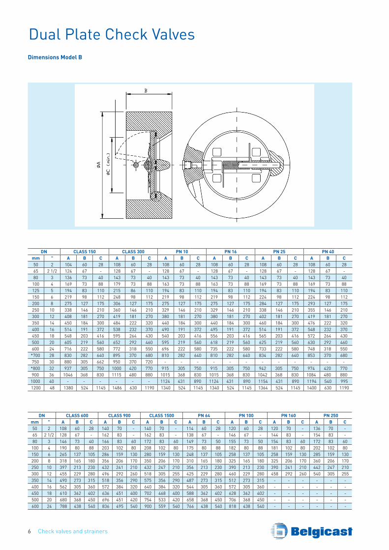
Dual Plate Check ValvesDimensions Model B
DN CLASS 150 CLASS 300 PN 10 PN 16 PN 25 PN 40mm " A B C A B C A B C A B C A B C A B C50 2 104 60 28 108 60 28 108 60 28 108 60 28 108 60 28 108 60 2865 2 1/2 124 67 - 128 67 - 128 67 - 128 67 - 128 67 - 128 67 -80 3 136 73 40 143 73 40 143 73 40 143 73 40 143 73 40 143 73 40
100 4 169 73 88 179 73 88 163 73 88 163 73 88 169 73 88 169 73 88125 5 194 83 110 215 86 110 194 83 110 194 83 110 194 83 110 194 83 110150 6 219 98 112 248 98 112 219 98 112 219 98 112 224 98 112 224 98 112200 8 275 127 175 306 127 175 275 127 175 275 127 175 284 127 175 293 127 175250 10 338 146 210 360 146 210 329 146 210 329 146 210 338 146 210 355 146 210300 12 408 181 270 419 181 270 380 181 270 380 181 270 402 181 270 419 181 270350 14 450 184 300 484 222 320 440 184 300 440 184 300 460 184 300 476 222 320400 16 514 191 372 538 232 370 490 191 372 495 191 372 514 191 372 548 232 370450 18 548 203 416 595 264 430 540 203 416 556 203 416 565 203 416 572 264 430500 20 605 219 560 652 292 460 595 219 560 618 219 560 625 219 560 630 292 460600 24 716 222 580 772 318 550 696 222 580 735 222 580 733 222 580 748 318 550*700 28 830 282 640 895 370 680 810 282 640 810 282 640 834 282 640 853 370 680750 30 880 305 662 950 370 720 - - - - - - - - - - - -*800 32 937 305 750 1000 420 770 915 305 750 915 305 750 942 305 750 974 420 770900 36 1046 368 830 1115 480 880 1015 368 830 1015 368 830 1042 368 830 1084 480 880
1000 40 - - - - - - 1124 431 890 1124 431 890 1154 431 890 1194 540 9951200 48 1380 524 1145 1486 630 1190 1340 524 1145 1340 524 1145 1364 524 1145 1400 630 1190
DN CLASS 600 CLASS 900 CLASS 1500 PN 64 PN 100 PN 160 PN 250mm " A B C A B C A B C A B C A B C A B C A B C50 2 108 60 28 140 70 - 140 70 - 114 60 28 120 60 28 120 70 - 136 70 -65 2 1/2 128 67 - 162 83 - 162 83 - 138 67 - 146 67 - 144 83 - 154 83 -80 3 146 73 40 166 83 60 172 83 60 149 73 50 155 73 50 154 83 60 172 83 60
100 4 190 80 88 203 102 80 208 102 80 175 80 88 182 80 88 181 102 80 202 102 80150 6 265 137 105 286 159 130 280 159 130 248 137 105 258 137 105 258 159 130 285 159 130200 8 318 165 180 356 206 170 350 206 170 310 165 180 325 165 180 325 206 170 360 206 170250 10 397 213 230 432 241 210 432 247 210 356 213 230 390 213 230 390 241 210 442 247 210300 12 455 229 280 496 292 260 518 305 255 425 229 280 460 229 280 458 292 260 540 305 255350 14 490 273 315 518 356 290 575 356 290 487 273 315 512 273 315 - - - - - -400 16 562 305 360 572 384 320 640 384 320 544 305 360 572 305 360 - - - - - -450 18 610 362 402 636 451 400 702 468 400 588 362 402 628 362 402 - - - - - -500 20 680 368 450 696 451 420 754 533 420 658 368 450 706 368 450 - - - - - -600 24 788 438 540 836 495 540 900 559 540 766 438 540 818 438 540 - - - - - -
Check valves and strainers 7
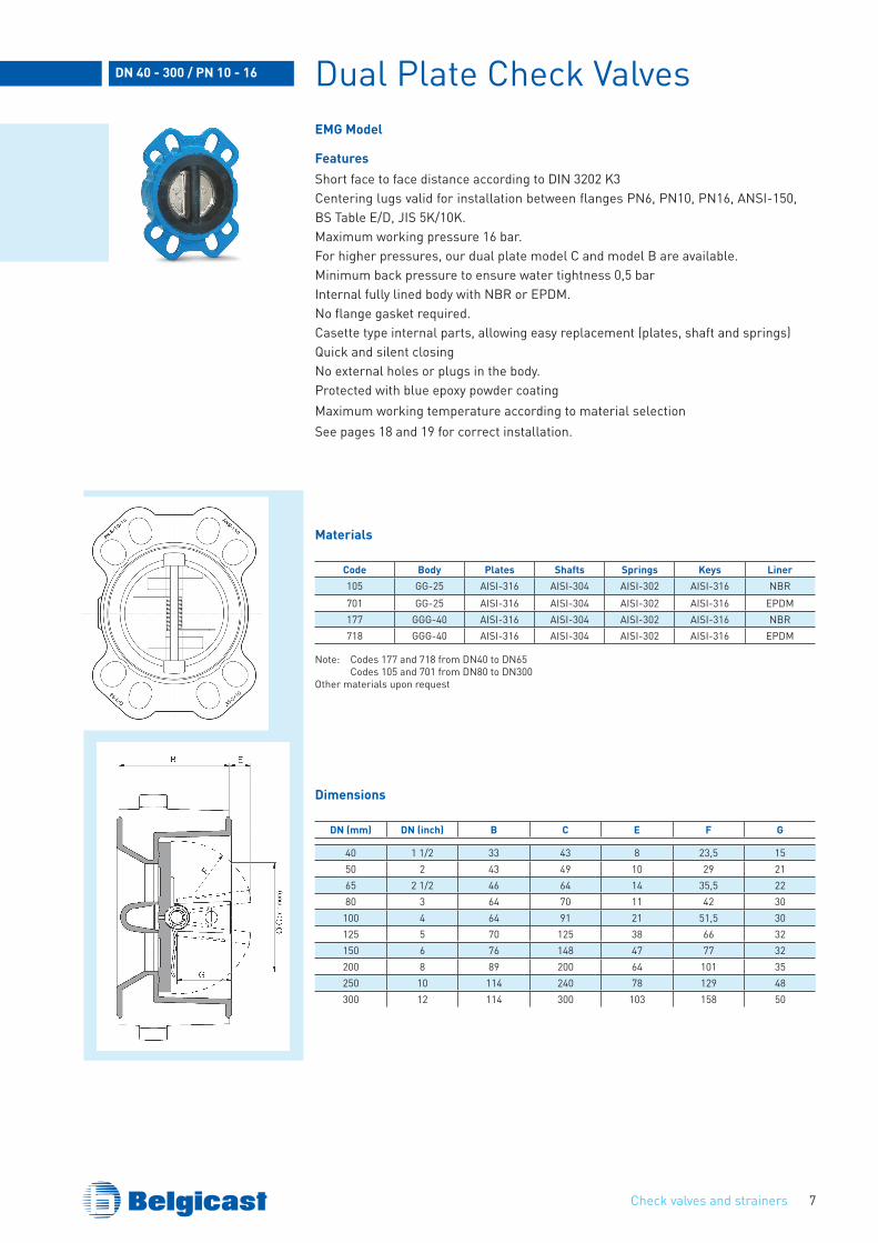
Dual Plate Check ValvesEMG Model
FeaturesShort face to face distance according to DIN 3202 K3Centering lugs valid for installation between flanges PN6, PN10, PN16, ANSI-150, BS Table E/D, JIS 5K/10K.Maximum working pressure 16 bar.For higher pressures, our dual plate model C and model B are available.Minimum back pressure to ensure water tightness 0,5 barInternal fully lined body with NBR or EPDM.No flange gasket required.Casette type internal parts, allowing easy replacement (plates, shaft and springs)Quick and silent closing No external holes or plugs in the body.Protected with blue epoxy powder coating Maximum working temperature according to material selectionSee pages 18 and 19 for correct installation.
DN 40 - 300 / PN 10 - 16
Materials
Code Body Plates Shafts Springs Keys Liner105 GG-25 AISI-316 AISI-304 AISI-302 AISI-316 NBR701 GG-25 AISI-316 AISI-304 AISI-302 AISI-316 EPDM177 GGG-40 AISI-316 AISI-304 AISI-302 AISI-316 NBR718 GGG-40 AISI-316 AISI-304 AISI-302 AISI-316 EPDM
Note: Codes 177 and 718 from DN40 to DN65 Codes 105 and 701 from DN80 to DN300Other materials upon request
DN (mm) DN (inch) B C E F G
40 1 1/2 33 43 8 23,5 1550 2 43 49 10 29 2165 2 1/2 46 64 14 35,5 2280 3 64 70 11 42 30
100 4 64 91 21 51,5 30125 5 70 125 38 66 32150 6 76 148 47 77 32200 8 89 200 64 101 35250 10 114 240 78 129 48300 12 114 300 103 158 50
Dimensions
Check valves and strainers8
Dual Plate Check ValvesRubber liner and applications
MATERIAL ISO CHEMICAL NAME WORKING TEMP. (oC)
EPDM
EPDM Ethylene-PropyleneTerpolymer
Water, weak mineral acids and basis, water ketones, esters –10o +80o
EPDM-HT
High temperature –10o +130o
Normative FDA –20o +130o
NITRILE NBRAcrylonitrile-
Butadiene Copolymer
Oils, Greases, Fuel, Gas oil, CO2, CO, H2
–10o +80o
HYPALON CSM ChlorosulfonatedPolyethylene
Moderate resistance to oil, greases and weak acids –20o +120o
VITON FPM
Hexafluorpropylene vinylidene fluoride copolymer Best chemical resistence –15o +200o
HFP-VDF-TFEterpolymer Oxygenated Gasoline –5o +70o
NATURAL NR 1,4 cisPolyisoprene Very good abrasion resistance –15o +70o
SILICONE
MVQ Poly methyl vinylsiloxane
Highest and lowest temperature resistance –60o +200o
STEAM SILICONE Steam water –60o +140o
Guidance information provided by rubber suppliers.Final performance of the rubber will depend on media composition.
Check valves and strainers 9
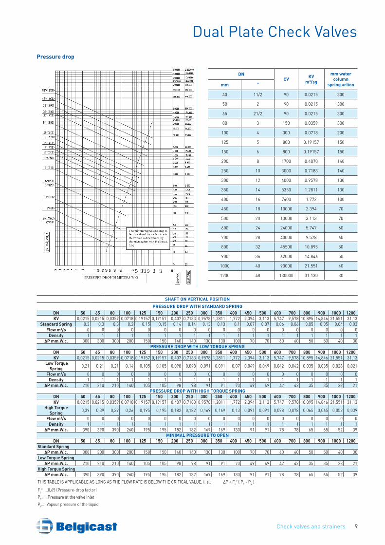
Dual Plate Check ValvesPressure drop
SHAFT ON vERTICAL POSITIONPRESSuRE DROP WITH STANDARD SPRING
DN 50 65 80 100 125 150 200 250 300 350 400 450 500 600 700 800 900 1000 1200Kv 0,0215 0,0215 0,0359 0,0718 0,19157 0,19157 0,407 0,7183 0,9578 1,2811 1,772 2,394 3,113 5,747 9,578 10,895 14,846 21,551 31,13
Standard Spring 0,3 0,3 0,3 0,2 0,15 0,15 0,14 0,14 0,13 0,13 0,1 0,07 0,07 0,06 0,06 0,05 0,05 0,04 0,03Flow m3/s 0 0 0 0 0 0 0 0 0 0 0 0 0 0 0 0 0 0 0
Density 1 1 1 1 1 1 1 1 1 1 1 1 1 1 1 1 1 1 1∆P mm.W.c. 300 300 300 200 150 150 140 140 130 130 100 70 70 60 60 50 50 40 30
PRESSuRE DROP WITH LOW TORquE SPRINGDN 50 65 80 100 125 150 200 250 300 350 400 450 500 600 700 800 900 1000 1200Kv 0,0215 0,0215 0,0359 0,0718 0,19157 0,19157 0,407 0,7183 0,9578 1,2811 1,772 2,394 3,113 5,747 9,578 10,895 14,846 21,551 31,13
Low Torque Spring 0,21 0,21 0,21 0,14 0,105 0,105 0,098 0,098 0,091 0,091 0,07 0,049 0,049 0,042 0,042 0,035 0,035 0,028 0,021
Flow m3/s 0 0 0 0 0 0 0 0 0 0 0 0 0 0 0 0 0 0 0Density 1 1 1 1 1 1 1 1 1 1 1 1 1 1 1 1 1 1 1
∆P mm.W.c. 210 210 210 140 105 105 98 98 91 91 70 49 49 42 42 35 35 28 21PRESSuRE DROP WITH HIGH TORquE SPRING
DN 50 65 80 100 125 150 200 250 300 350 400 450 500 600 700 800 900 1000 1200Kv 0,0215 0,0215 0,0359 0,0718 0,19157 0,19157 0,407 0,7183 0,9578 1,2811 1,772 2,394 3,113 5,747 9,578 10,895 14,846 21,551 31,13
High Torque Spring 0,39 0,39 0,39 0,26 0,195 0,195 0,182 0,182 0,169 0,169 0,13 0,091 0,091 0,078 0,078 0,065 0,065 0,052 0,039
Flow m3/s 0 0 0 0 0 0 0 0 0 0 0 0 0 0 0 0 0 0 0Density 1 1 1 1 1 1 1 1 1 1 1 1 1 1 1 1 1 1 1
∆P mm.W.c. 390 390 390 260 195 195 182 182 169 169 130 91 91 78 78 65 65 52 39MINIMAL PRESSuRE TO OPEN
DN 50 65 80 100 125 150 200 250 300 350 400 450 500 600 700 800 900 1000 1200Standard Spring
∆P mm.W.c. 300 300 300 200 150 150 140 140 130 130 100 70 70 60 60 50 50 40 30Low Torque Spring
∆P mm.W.c. 210 210 210 140 105 105 98 98 91 91 70 49 49 42 42 35 35 28 21High Torque Spring
∆P mm.W.c. 390 390 390 260 195 195 182 182 169 169 130 91 91 78 78 65 65 52 39THIS TABLE IS APPLICABLE AS LONG AS THE FLOW RATE IS BELOW THE CRITICAL VALUE, i. e.: ∆P < FL
2 ( P1 - PV )
FL2…..0,65 (Pressure-drop factor)
P1……Pressure at the valve inletPV…..Vapour pressure of the liquid
DNCv Kv
m3/sg
mm watercolumn
spring actionmm “
40 11/2 90 0.0215 300
50 2 90 0.0215 300
65 21/2 90 0.0215 300
80 3 150 0.0359 300
100 4 300 0.0718 200
125 5 800 0.19157 150
150 6 800 0.19157 150
200 8 1700 0.4070 140
250 10 3000 0.7183 140
300 12 4000 0.9578 130
350 14 5350 1.2811 130
400 16 7400 1.772 100
450 18 10000 2.394 70
500 20 13000 3.113 70
600 24 24000 5.747 60
700 28 40000 9.578 60
800 32 45500 10.895 50
900 36 62000 14.846 50
1000 40 90000 21.551 40
1200 48 130000 31.130 30
Check valves and strainers10
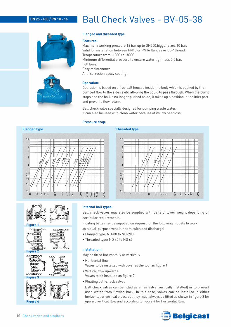
Ball Check Valves - BV-05-38Flanged and threaded type
Features:Maximum working pressure 16 bar up to DN200,bigger sizes 10 bar.Valid for installation between PN10 or PN16 flanges or BSP thread.Temperature from -10ºC to +80ºCMinimum differential pressure to ensure water tightness 0,5 bar.Full bore.Easy maintenance.Anti-corrosion epoxy coating.
Operation:Operation is based on a free ball housed inside the body which is pushed by thepumped flow to the side cavity, allowing the liquid to pass through. When the pumpstops and the ball is no longer pushed aside, it takes up a position in the inlet portand prevents flow return.
Ball check valve specially designed for pumping waste water.It can also be used with clean water because of its low headloss.
DN 25 - 400 / PN 10 - 16
Internal ball types:Ball check valves may also be supplied with balls of lower weight depending on particular requirements.Floating balls may be supplied on request for the following models to workas a dual-purpose vent (air admission and discharge):• Flanged type: ND-80 to ND-200• Threaded type: ND 40 to ND 65
Installation:May be fitted horizontally or vertically.• Horizontal flow
Valves to be installed with cover at the top, as figure 1 • Vertical flow upwards
Valves to be installed as figure 2• Floating ball-check valves Ball check valves can be fitted as an air valve (vertically installed) or to prevent
used water from flowing back. In this case, valves can be installed in either horizontal or vertical pipes, but they must always be fitted as shown in figure 3 for upward vertical flow and according to figure 4 for horizontal flow.
Pressure drop:
Flanged type Threaded type
Figure 1
Figure 2
Figure 3
Figure 4
Check valves and strainers 11
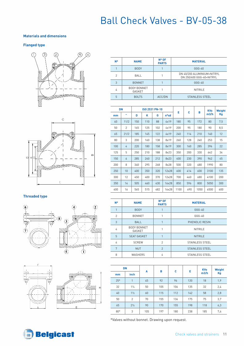
Ball Check Valves - BV-05-38Materials and dimensions
DN ISO 2531 PN-10E C B Kvo
m3/hWeight
Kgmm “ D K G nºxd
40 11/2 150 110 88 4x19 180 95 172 80 7,5
50 2 165 125 102 4x19 200 95 180 90 8,5
65 21/2 185 145 122 4x19 240 114 210 140 12
80 3 200 160 138 8x19 260 128 240 253 15
100 4 220 180 158 8x19 300 160 285 396 22
125 5 250 210 188 8x23 350 200 330 642 34
150 6 285 240 212 8x23 400 230 390 962 45
200 8 340 295 268 8x28 500 320 480 1990 80
250 10 400 350 320 12x28 600 414 600 3100 135
300 12 450 400 370 12x28 700 460 680 4100 200
350 14 505 460 430 16x28 850 596 800 5050 300
400 16 565 515 482 16x28 1100 690 1050 6500 600
Nº NAME Nº OF PARTS MATERIAL
1 BODY 1 GGG-40
2 BALL 1 DN 40/200 ALUMINIUM+NITRYLDN 250/400 GGG-40+NITRYL
3 BONNET 1 GGG-40
4 BODY BONNET GASKET 1 NITRILE
5 BOLTS ACC/DN STAINLESS STEEL
Nº NAME Nº OF PARTS MATERIAL
1 BODY 1 GGG-40
2 BONNET 1 GGG-40
3 BALL 1 PHENOLIC RESIN
4 BODY BONNET GASKET 1 NITRILE
5 SEAT GASKET 1 NITRILE
6 SCREW 2 STAINLESS STEEL
7 NUT 2 STAINLESS STEEL
8 WASHERS 4 STAINLESS STEEL
DNA B C E Kvo
m3/hWeight
Kgmm inch
25* 1 45 92 96 120 18 1,9
32 1¼ 50 105 106 135 32 2,4
40 1½ 60 115 112 142 58 2,8
50 2 70 155 136 175 75 3,7
65 2½ 90 170 155 198 118 6,3
80* 3 105 197 180 238 185 7,6
*Valves without bonnet. Drawing upon request.
Flanged type
Threaded type
Check valves and strainers12
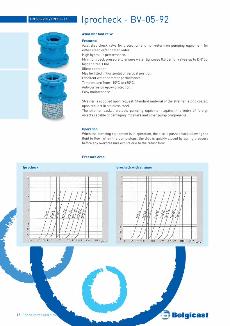
Iprocheck - BV-05-92Axial disc foot valve
Features:Axial disc check valve for protection and non-return on pumping equipment for either clean or/and filter water.High hydraulic performance.Minimum back pressure to ensure water tightness 0,5 bar for valves up to DN150, bigger sizes 1 bar.Silent operation.May be fitted in horizontal or vertical position.Excellent water hammer performance.Temperature from -10ºC to +80ºC.Anti-corrosion epoxy protection.Easy maintenance
Strainer is supplied upon request. Standard material of the strainer is zinc coated, upon request in stainless steel.The strainer basket protects pumping equipment against the entry of foreign objects capable of damaging impellers and other pump components.
Operation:When the pumping equipment is in operation, the disc is pushed back allowing thefluid to flow. When the pump stops, the disc is quickly closed by spring pressure before any overpressure occurs due to the return flow.
Pressure drop:
DN 50 - 250 / PN 10 - 16
Iprocheck Iprocheck with strainer
Check valves and strainers 13
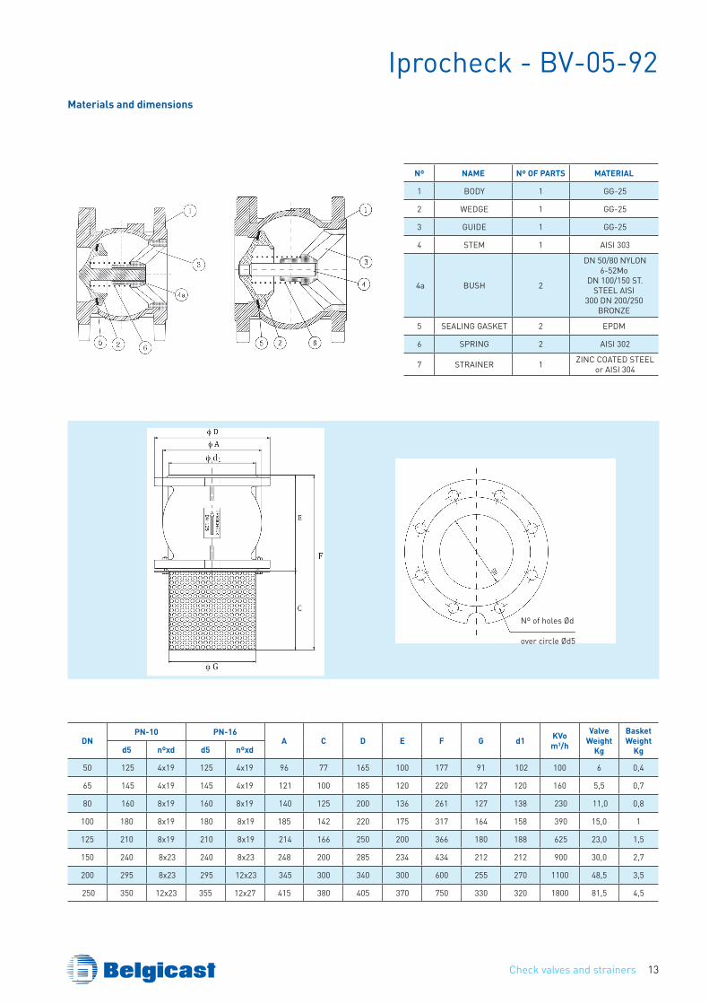
Iprocheck - BV-05-92Materials and dimensions
Nº NAME Nº OF PARTS MATERIAL
1 BODY 1 GG-25
2 WEDGE 1 GG-25
3 GUIDE 1 GG-25
4 STEM 1 AISI 303
4a BUSH 2
DN 50/80 NYLON 6-52Mo
DN 100/150 ST. STEEL AISI
300 DN 200/250 BRONZE
5 SEALING GASKET 2 EPDM
6 SPRING 2 AISI 302
7 STRAINER 1 ZINC COATED STEEL or AISI 304
DNPN-10 PN-16
A C D E F G d1 Kvom3/h
valveWeight
Kg
BasketWeight
Kgd5 nºxd d5 nºxd
50 125 4x19 125 4x19 96 77 165 100 177 91 102 100 6 0,4
65 145 4x19 145 4x19 121 100 185 120 220 127 120 160 5,5 0,7
80 160 8x19 160 8x19 140 125 200 136 261 127 138 230 11,0 0,8
100 180 8x19 180 8x19 185 142 220 175 317 164 158 390 15,0 1
125 210 8x19 210 8x19 214 166 250 200 366 180 188 625 23,0 1,5
150 240 8x23 240 8x23 248 200 285 234 434 212 212 900 30,0 2,7
200 295 8x23 295 12x23 345 300 340 300 600 255 270 1100 48,5 3,5
250 350 12x23 355 12x27 415 380 405 370 750 330 320 1800 81,5 4,5
Nº of holes Ød
over circle Ød5
Check valves and strainers14
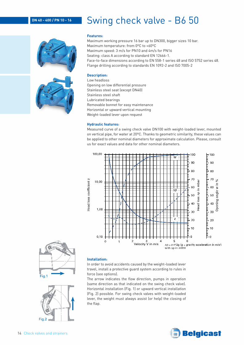
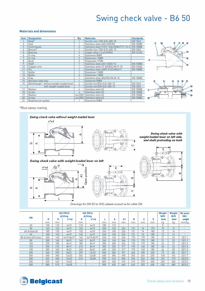
Swing check valve - B6 50Features:Maximum working pressure 16 bar up to DN300, bigger sizes 10 bar.Maximum temperature: from 0ºC to +60ºCMaximum speed: 3 m/s for PN10 and 4m/s for PN16Seating: class A according to standard EN 12666-1.Face-to-face dimensions according to EN 558-1 series 48 and ISO 5752 series 48.Flange drilling according to standards EN 1092-2 and ISO 7005-2
Description:Low headlossOpening on low differential pressureStainless steel seat (except DN40)Stainless steel shaftLubricated bearingsRemovable bonnet for easy maintenanceHorizontal or upward vertical mountingWeight-loaded lever upon request
Hydraulic features:Measured curve of a swing check valve DN100 with weight-loaded lever, mounted on vertical pipe, for water at 20ºC. Thanks to geometric similarity, these values can be applied to other nominal diameters for approximate calculation. Please, consult us for exact values and data for other nominal diameters.
DN 40 - 400 / PN 10 - 16
Installation:ln order to avoid accidents caused by the weight-loaded lever travel, install a protective guard system according to rules in force (see options).The arrow indicates the flow direction, pumps in operation (same direction as that indicated on the swing check valve). Horizontal installation (Fig. 1) or upward vertical installation (Fig. 2) possible. For swing check valves with weight-loaded lever, the weight must always assist (or help) the closing of the flap.
Check valves and strainers 15
Swing check valve - B6 50Materials and dimensions
Item Designation qty Materials Standards1 Body* 1 Ductile iron / EN-GJS-400-15 EN 15632 Seat 1 Stainless steel 420/ X30CN3 EN 100883 Centring pin 2 Stainless steel 316TÍ / X6CrNiMoTi17-12-2 EN 100884 Bonnet* 1 Ductile iron / EN-GJS-400-15 EN 15635 Bearing 2 Copper alloy / CuZn39Pb3 EN 121656 O-ring 4 Elastomer/NBR7 O-ring 2 Elastomer / NBR8 Bush 2 Polyacetal / POM9 Shaft 1 Stainless steel 420 / X20Cr13 EN 10088
10 Clapper arm 1 Stainless steel CF-8/GX5CrNi19-10 EN 1028311 Pin 1 Stainless steel 430F/ X14CrMoS17 EN 1008812 Buffer 1 Elastomer / NBR13 Buffer 2 Elastomer / NBR14 Flap 1 Stainless steel 304/X5CrNi18-10 EN 1008815 Resilient valve disc 1 Elastomer/NBR16 Blind flange*: without weight-loaded lever 2 Ductile iron/EN-GJS-400-15 EN 1563
with weight-loaded lever 1 Ductile iron/EN-GJS-400-15 EN 156317 Washer 4 Stainless steel A2 EN 1008818 Screw 4 Stainless steel A2 EN 1008819 Washer acc/DN Stainless steel A2 EN 1008820 Screw acc/DN Stainless steel A2 EN 1008821 Body/bonnet gasket 1 Elastomer/NBR
DN
ISO PN10 ISO PN16 Weight Weight By-passdrilling drilling W/O W/O DN /
D K n°xd K n°xd L A A1 B C E lever lever weightmm mm mm mm mm mm mm mm mm kg kg mm/kg
40 150 110 4x19 110 4x19 180 115 - - - - 8 - -50 165 125 4x19 125 4x19 200 105 226 131 74 170 10 12 -
65 drilled 60 185 135 4x19 135 4x19 240 105 226 131 74 180 12 14 -65 185 145 4x19 145 4x19 240 105 226 131 74 180 12 14 -
80 drilled 4/8 holes 200 160 4x19+8x19 160 4x19+8x19 260 145 264 170 170 180 21 23 15/1.180 200 160 8x19 160 8x19 260 145 264 170 170 180 21 23 15/1.1
100 220 180 8x19 180 8x19 300 200 264 170 170 180 24 27 20/1.5125 250 210 8x19 210 8x19 350 220 317 195 140 180 40 43 20/1.5150 285 240 8x23 240 8x23 400 230 317 195 140 180 46 50 20/1.5200 340 295 8x23 295 12x23 500 300 391 265 185 230 75 80 25/1.7250 400 350 12x23 355 12x28 600 385 490 355 245 230 148 154 25/1.7300 455 400 12x23 410 12x28 700 410 500 355 245 250 169 175 32/2.0350 520 460 16x23 - - 800 400 610 415 278 400 320 360 32/2.0400 580 515 16x28 - - 900 455 660 445 325 400 430 480 40/3.0
*Blue epoxy coating.
Check valves and strainers16
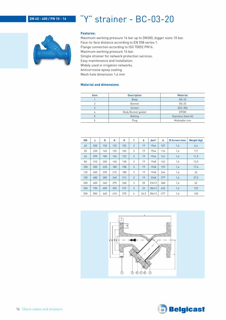
“Y” strainer - BC-03-20Features:Maximum working pressure 16 bar up to DN300, bigger sizes 10 bar.Face-to-face distance according to EN 558 series 1.Flange connection according to ISO 70052 PN16.Maximum working pressure 16 bar.Simple strainer for network protection services.Easy maintenance and installation.Widely used in irrigation networks.Anticorrosive epoxy coating.Mesh hole dimension 1,6 mm
DN 40 - 400 / PN 10 - 16
Item Description Material1 Body GG-252 Bonnet GG-253 Screen AISI-3044 Body Bonnet gasket EPDM5 Bolting Stainless Steel A26 Plug Malleable iron
DN L D K G f b dxnº A Ø Screen hole Weight (kg)
40 200 150 125 102 3 19 19x4 107 1,6 6,4
50 230 165 125 102 3 19 19x4 116 1,6 7,9
65 290 185 145 122 3 19 19x4 141 1,6 11,5
80 310 200 160 138 3 19 19x8 162 1,6 13,5
100 350 220 180 158 3 19 19x8 192 1,6 17,6
125 400 250 210 188 3 19 19x8 244 1,6 26
150 480 285 240 212 3 19 23x8 277 1,6 37,5
200 600 340 295 268 3 20 23x12 348 1,6 62
250 730 405 355 319 3 22 28x12 433 1,6 122
300 850 460 410 370 4 24,5 28x12 477 1,6 160
Material and dimensions
Check valves and strainers 17
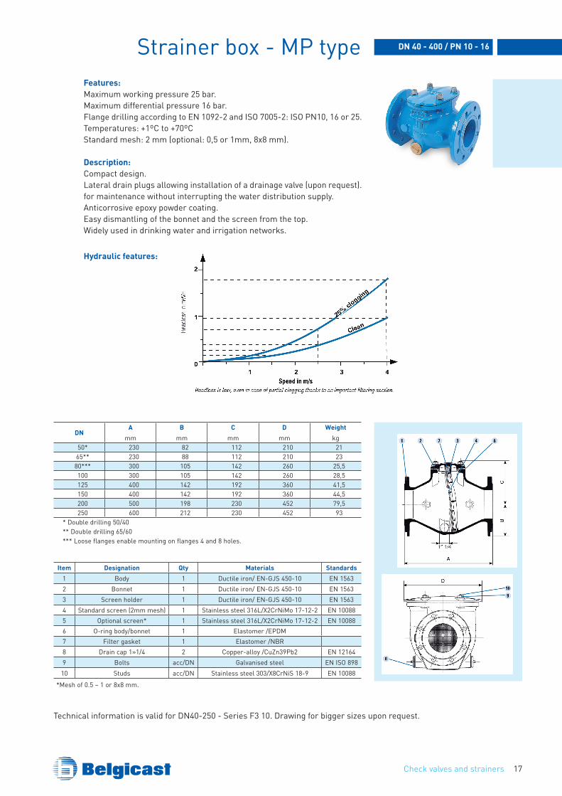
Strainer box - MP typeFeatures:Maximum working pressure 25 bar.Maximum differential pressure 16 bar.Flange drilling according to EN 1092-2 and ISO 7005-2: ISO PN10, 16 or 25.Temperatures: +1ºC to +70ºCStandard mesh: 2 mm (optional: 0,5 or 1mm, 8x8 mm).
Description:Compact design.Lateral drain plugs allowing installation of a drainage valve (upon request). for maintenance without interrupting the water distribution supply.Anticorrosive epoxy powder coating.Easy dismantling of the bonnet and the screen from the top.Widely used in drinking water and irrigation networks.
DN 40 - 400 / PN 10 - 16
Hydraulic features:
DNA
mmB
mmC
mmD
mmWeight
kg50* 230 82 112 210 2165** 230 88 112 210 2380*** 300 105 142 260 25,5100 300 105 142 260 28,5125 400 142 192 360 41,5150 400 142 192 360 44,5200 500 198 230 452 79,5250 600 212 230 452 93
* Double drilling 50/40** Double drilling 65/60*** Loose flanges enable mounting on flanges 4 and 8 holes.
Item Designation qty Materials Standards1 Body 1 Ductile iron/ EN-GJS 450-10 EN 15632 Bonnet 1 Ductile iron/ EN-GJS 450-10 EN 15633 Screen holder 1 Ductile iron/ EN-GJS 450-10 EN 15634 Standard screen (2mm mesh) 1 Stainless steel 316L/X2CrNiMo 17-12-2 EN 100885 Optional screen* 1 Stainless steel 316L/X2CrNiMo 17-12-2 EN 100886 O-ring body/bonnet 1 Elastomer /EPDM7 Filter gasket 1 Elastomer /NBR8 Drain cap 1»1/4 2 Copper-alloy /CuZn39Pb2 EN 121649 Bolts acc/DN Galvanised steel EN ISO 898
10 Studs acc/DN Stainless steel 303/X8CrNiS 18-9 EN 10088
*Mesh of 0.5 – 1 or 8x8 mm.
Technical information is valid for DN40-250 - Series F3 10. Drawing for bigger sizes upon request.
Check valves and strainers18
Installation and use instructions
Assembly in pipe
Wafer assembly: valves must be installed between pipe flanges with bolts or through studs, placing applicable gaskets between valve and flange faces. The valve body outside diameter is guided and centered by bolts or through studs used for valve mounting on pipe flanges.Flanged type: bolts must be tightened gradually and diagonally following a pattern that ensures that none are completely tightened while the rest are completely loose.
Minimum pressure for tightnessFor BELGICAST dual plate check valves and ball check valves the minimum pressure for tightness (backpressure on the plates/ball) is 0,5 bar (5 water column meters).
Mounting precautions A proper performance of a check valve requires that the flow is as uniform as possible and that turbulence is minimized, to avoid that when the valve is opened, the plates can be opened and closed in rotation angle next to the total opening position, producing the rapid wear of the washers and the side faces of the hinges of the plates.Check valves can be installed on horizontal or vertical pipes with upwards or downwards fluid flow, however the following precautions should be noticed:
Dual plate check valves
• Horizontal flowValves must be mounted with the disc rotation axis in vertical position, such that the discs seat on the support rings and have a balanced swing taking the same stress
• vertical flow upwardsThere is no definite position for the disk axis in this case, any direction being acceptable, selecting the most adequate direction depending on the pipe layout.For this valve arrangement, the seat takes the disc weight, and an additional pressure drop takes place. In these cases and for diameters above 6“, mounting low torque springs for counteracting the disk weight effect is recommended.
• vertical flow downwardsRegarding the disc axis, the above stated applies.For this valve arrangement, the disk weight is in the opening direction, and this must be known in advance to be able to mount high torque springs for valve diameters greater than 6“.
Check valves and strainers 19
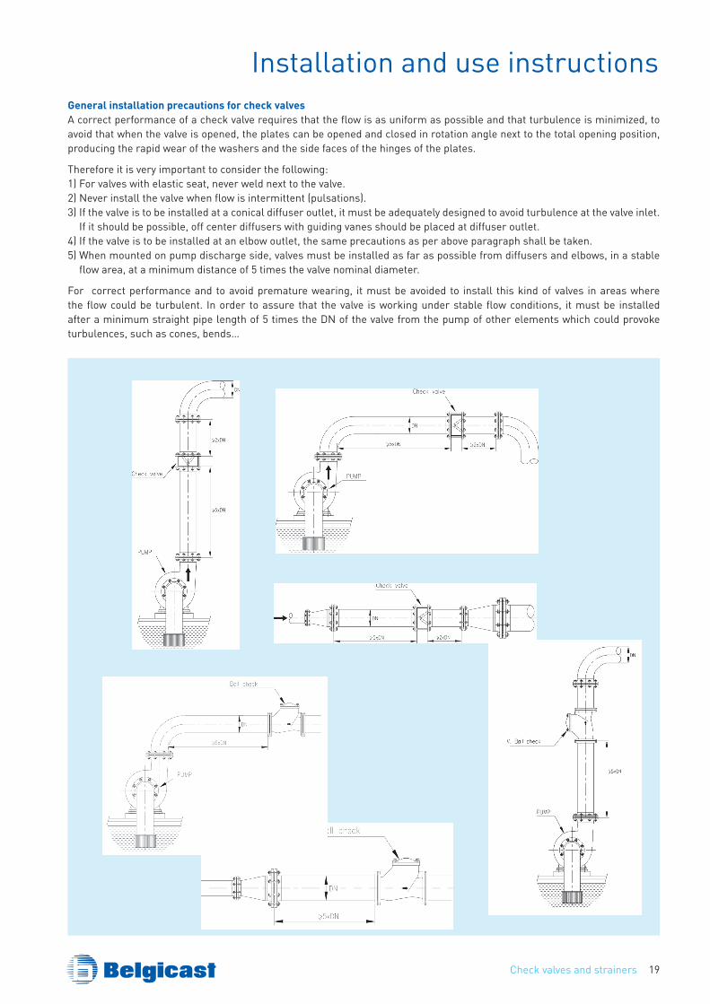
Installation and use instructionsGeneral installation precautions for check valvesA correct performance of a check valve requires that the flow is as uniform as possible and that turbulence is minimized, to avoid that when the valve is opened, the plates can be opened and closed in rotation angle next to the total opening position, producing the rapid wear of the washers and the side faces of the hinges of the plates.
Therefore it is very important to consider the following: 1) For valves with elastic seat, never weld next to the valve.2) Never install the valve when flow is intermittent (pulsations).3) If the valve is to be installed at a conical diffuser outlet, it must be adequately designed to avoid turbulence at the valve inlet.
If it should be possible, off center diffusers with guiding vanes should be placed at diffuser outlet.4) If the valve is to be installed at an elbow outlet, the same precautions as per above paragraph shall be taken.5) When mounted on pump discharge side, valves must be installed as far as possible from diffusers and elbows, in a stable
flow area, at a minimum distance of 5 times the valve nominal diameter.
For correct performance and to avoid premature wearing, it must be avoided to install this kind of valves in areas where the flow could be turbulent. In order to assure that the valve is working under stable flow conditions, it must be installed after a minimum straight pipe length of 5 times the DN of the valve from the pump of other elements which could provoke turbulences, such as cones, bends…
Butterfly Valves20
TALIS is always the number one choice whenever water transport or control is required. TALIS has the best solution for water and energy management, as well as for industry and municipal applications. With a varied range of products, we offer comprehensive solutions for the entire water cycle. From hydrants to butterfly valves. From service connection valves to needle valves. Our experience, innovative technology, global expertise and individual consultation process form the basis for developing sustainable solutions for the efficient handling of the vital resource “water”.
Your choice in waterflow control
Belgicast Internacional, S.L.Bº Zabalondo 3148100 Munguía (Vizcaya)Nacional • Tel: 94 488 91 00 • Fax: 94 488 91 30Export • Tel: +34 94 488 91 20 • Fax: +34 94 488 91 [email protected] www.belgicast.eu
Note: Specifications may be changed without notification at any timeCopyright: No copying without express written permission of BELGICASTBELGICAST is a Registered Trademark 2.
000
– 11
/201
2

![8117.1 02 EN - shop.ksb.com · Check Valves and Strainers. Nozzle Check Valves to DIN/EN 5. BOA-RFV. Pressure/temperature ratings. Permissible operating pressures [bar] (to EN 12266-1)](https://static.cupdf.com/doc/110x72/5dd0891dd6be591ccb61764a/81171-02-en-shopksbcom-check-valves-and-strainers-nozzle-check-valves-to-dinen.jpg)