International Journal of Digital Evidence Fall 2003, Volume 2, Issue 2
An Evaluation of Image Based Steganography Methods
Kevin Curran, Internet Technologies Research Group, University of Ulster Karen Bailey, Institute of Technology, Letterkenny, Ireland
Abstract - Steganography is a process that involves hiding a message in an appropriate carrier
for example an image or an audio file. The carrier can then be sent to a receiver without
anyone else knowing that it contains a hidden message. This is a process, which can be used
for example by civil rights organisations in repressive states to communicate their message to
the outside world without their own government being aware of it. Less virtuously it can be
used by terrorists to communicate with one another without anyone else’s knowledge. In both
cases the objective is not to make it difficult to read the message as cryptography does, it is to
hide the existence of the message in the first place possibly to protect the courier.
The initial aim of this study was to investigate steganography and how it is implemented.
Based on this work a number of common methods of steganography could then be
implemented and evaluated. The strengths and weaknesses of the chosen methods can then be
analysed. To provide a common frame of reference all of the steganography methods
implemented and analysed used GIF images. Seven steganography methods were
implemented. The methods were chosen for their different strengths in terms of resistance to
different types of steganalysis or their ability to maximise the size of the message they could
store. All of the methods used were based on the manipulation of the least significant bits of
pixel values or the rearrangement of colours to create least significant bit or parity bit
patterns, which correspond to the message being hidden.
1 INTRODUCTION The word steganography means "covered or hidden writing" [Johnson01]. The object of
steganography is to send a message through some innocuous carrier (to a receiver while
preventing anyone else from knowing that a message is being sent at all. Computer based
stenography allows changes to be made to what are known as digital carriers such as images
or sounds. The changes represent the hidden message, but result if successful in no
discernible change to the carrier. The information may be nothing to do with the carrier sound
or image or it might be information about the carrier such as the author or a digital watermark
or fingerprint [Johnson01].
Cryptography and steganography are different. Cryptographic techniques can be used to
scramble a message so that if it is discovered it cannot be read. If a cryptographic message is
www.ijde.org
1
International Journal of Digital Evidence Fall 2003, Volume 2, Issue 2 discovered it is generally known to be a piece of hidden information (anyone intercepting it
will be suspicious) but it is scrambled so that it is difficult or impossible to understand and de-
code. Steganography hides the very existence of a message so that if successful it generally
attracts no suspicion at all. Using steganography, information can be hidden in carriers such
as images, audio files, text files, videos and data transmissions [Johnson01]. When the
message is hidden in the carrier a stego-carrier is formed for example a stego-image.
Hopefully it will be perceived to be as close as possible to the original carrier or cover image
by the human senses. Images are the most widespread carrier medium [Westfield99]. They
are used for steganography in the following way. The message may firstly be encrypted. The
sender (or embedder [Pfitzmann96]) embeds the secret message to be sent into a graphic file
[Zollner98] (the cover image [Pfitzmann96] or the carrier). This results in the production of
what is called a stego-image. Additional secret data may be needed in the hiding process e.g.
a stegokey. The stego-image is then transmitted to the recipient [Zollner98]. The recipient (or
extractor [Pfitzmann96]) extracts the message from the carrier image. The message can only
be extracted if there is a shared secret between the sender and the recipient. This could be the
algorithm for extraction or a special parameter such as a key [Zollner98] (the stegokey). A
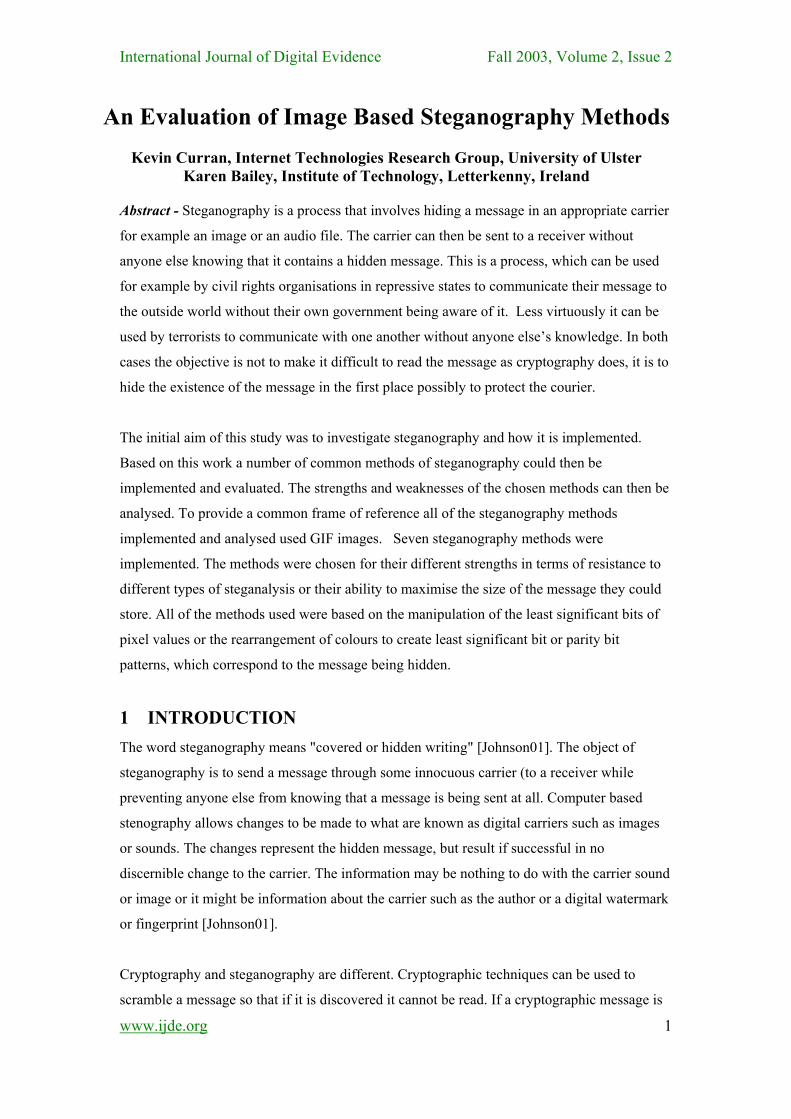
stegoanalyst or attacker may try to intercept the stego-image. Figure 1 below shows the
steganographic system.
Figure 1 : The Steganographic System [Westfield99].
To make a steganographic communication even more secure the message can be compressed
and encrypted before being hidden in the carrier. Cryptography and steganography can be
used together. If compressed the message will take up far less space in the carrier and will
minimise the information to be sent. The random looking message which would result from
encryption and compression would also be easier to hide than a message with a high degree of
regularity. Therefore encryption and compression are recommended in conjunction with
steganography [Fridrich99].
www.ijde.org
2
International Journal of Digital Evidence Fall 2003, Volume 2, Issue 2 1.1 TYPES OF DIGITAL CARRIERS
There are a variety of digital carriers or places where data can be hidden. Data may be
embedded in files at imperceptible levels as noise. Properties of images can be manipulated
including luminescence, contrast and colours [Johnson01]. In audio files small echoes or
slight delays can be included or subtle signals can be masked with sounds of higher
amplitude. Information can be hidden in documents by manipulating the positions of the lines
or the words. When HTML files are written web browsers ignore spaces, tabs, certain
characters and extra line breaks. These could be used as locations in which to hide
information. Messages can be retrieved from text by taking for example the second letter of
each word and using them to produce the hidden message. This is called a null cipher or open
code [Johnson01]. Information can be hidden in the layout of a document for example certain
words in a piece of text can be shifted very slightly from their positions and these shifted
words can then make up the hidden message. The way a language is spoken can be used to
encode a message such as pauses, enunciations and throat clearing [Johnson01].
Unused or reserved space on a disc can be used to hide information. The way operating
systems store files typically results in unused space that appears to be allocated to the files. A
minimum amount of space may be allocated to files but the file does not need all this space so
some of it goes unused. This space can be used to hide information. Another method for
hiding information in file systems is to create a hidden partition [Johnson01]. Data may be
hidden in unused space in file headers. Packets for example TCP / IP packets have headers
with unused space and other features that can be manipulated to embed information
[Johnson01]. Data can be hidden using the physical arrangement of a carrier for example the
layout of code in a program or electronic circuits on a board. This process can be used to
record and identify the origin of the design and cannot be removed without a substantial
change to the physical layout. Spread spectrum techniques can also be used by placing an
audio signal over a number of different frequencies. Random number generators are
developed to allow spread spectrum radios to hop from frequency to frequency. Systems can
use different frequencies at the same time. Some information is broadcast on one frequency
and some on another. The message can be reassembled by combining all the information
[Wayner02].
www.ijde.org
3

International Journal of Digital Evidence Fall 2003, Volume 2, Issue 2 1.2 IMAGE STRUCTURE AND IMAGE PROCESSING
A digital image is the most common type of carrier used for steganography. A digital image is
produced using a camera, scanner or other device. The digital representation is an
approximation of the original image [Efford00]. The system used for producing the image
focuses a two dimensional pattern of varying light intensity and colour onto a sensor
[Efford00]. The pattern has a co-ordinate system and the origin is the upper left hand corner
of the image. The pattern can be described by a function f(x, y). An image can be described as
an array of numbers that represent light intensities at various points. These light intensities or
instances of colour are called pixels. Sampling is the process of measuring the value of the
image function f(x, y) at discrete intervals in space [Efford00]. Each sample is the small
square area of the image known as the pixel. The raster data of an image is that part of the
image that can be seen i.e. the pixels [Johnson01]. The size of an image can be given in
pixels, for example an image which is 640 x 480 pixels contains 307,200 pixels
[Johnson01]Pixels are indexed by x and y co-ordinates with x and y having integer values
[Efford00]. The spatial resolution of an image is the physical size of the pixel in the image.
Dense sampling produces a high-resolution image in which there are many pixels and each
contributes a small part of the scene. Coarse sampling results in a low-resolution image in
which there are fewer pixels [Efford00]. The rate of change of the value f(x, y) as it moves
across the image is the spatial frequency. Gradual changes in f(x, y) correspond to low spatial
frequencies and can be represented in a coarsely sampled image. Rapid changes correspond to
high spatial frequencies and must be represented by a densely sampled image. The Nyquist
criterion states that the sampling frequency should be at least double the highest spatial
frequency found in the image. A coarsely sampled image that does not follow this criterion
may suffer from the effects of aliasing [Efford00] shown in Figure 2 below.
a. b.
Figure 2: a. Image without Aliasing b. Coarsely Sampled Image Showing Aliasing Artefacts (Efford, 2000).
www.ijde.org
4
International Journal of Digital Evidence Fall 2003, Volume 2, Issue 2 Each pixel is generally stored as 24-bit or 8-bit. A 24-bit pixel has a possibility of 224 colour
combinations [Johnson01]The 24 bits of a 24-bit image are spread over three bytes and each
byte represents red, green and blue respectively. Colours are obtained by mixing red, green
and blue light in different proportions. An image can be formed by making three
measurements of brightness at each pixel using the red, green and blue components of the
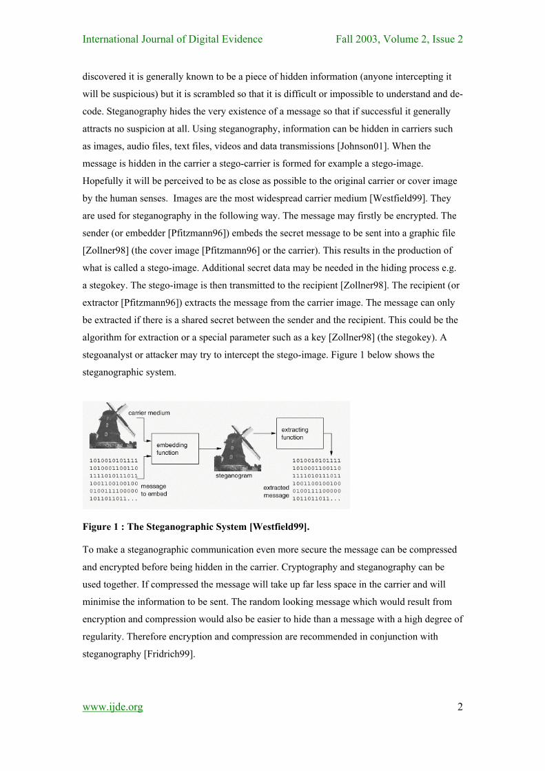
detected light. Using the RGB model the value of f(x, y) is a vector with three components
corresponding to red (R), green (G) and blue (B). They can be regarded as orthogonal axes
defining a three dimensional colour space. Every value of f(x, y) is a point in the colour cube
shown in Figure 3 below. The three components are normally quantised using 8 bits. An
image made of these components is described as a 24-bit colour image [Efford00].
Each byte can have a value from 0 to 255 representing the intensity of the colour. The darkest
colour value is 0 and the brightest is 255. For example a pixel could be made up of three bytes
as follows: 11111111 00000000 00000000. The first 8 bits represent red, the second 8 bits
represent green and the third 8 bits represent blue. The bit values in this example result in a
red pixel. Its red byte is at a maximum value (11111111) and its green (00000000) and blue
(00000000) bytes have the lowest possible value. Transparency is controlled by the addition
of information to each element of the pixel data. This is to allow image overlay [Murray96].
A 24-bit pixel value can be stored in 32 bits. The extra 8 bits specify transparency. This is
sometimes called the alpha channel [Murray96]. An ideal 8-bit alpha channel can support
transparency levels from 0 (completely transparent) to 255 (completely opaque). It can be
stored as part of the pixel data [Murray96] e.g. RGBA (red, green, blue and alpha taking up 4
bytes in total).
Figure 3 : The RGB Colour Cube (Efford, 2000)
Some images are 8-bit. Each pixel is represented by one byte only. This one byte can have
any value ranging from 0 to 255, 256 possible colours or 256 greyscale values for black and www.ijde.org
5
International Journal of Digital Evidence Fall 2003, Volume 2, Issue 2 white images. The colours are taken from a colour index or palette also called a colour map or
colour table. This palette contains up to 256 colours representing the colours in the image.
The value of the pixel in an image points to a colour in the palette [Johnson01]The GIF
(Graphic Interchange Format) image format uses this process. When a GIF image is displayed
the software paints the specified colour from the palette onto the screen [Johnson01] at each
pixel. If the image has fewer colours than the size of the palette any unused colours in the
palette are set to zero [Murray96] GIF is a bitmap image. Bitmap is a system in which an
image is described as a bit pattern or series of numbers that gives the shade or colour of each
pixel [Day98]. In true greyscale images, values from 0 to 255 represent the intensity of the
colour and do not refer to a palette [Johnson01]A palette image format contains a header, a
palette and image data (pointers to the palette).
There are two steps in creating palette-based images - colour quantisation and dithering
[Fridrich99]. A colour quantisation algorithm has two parts, generating the colour palette and
mapping the pixels. To generate the palette, colours are extracted from the image. Each pixel
in the image is then mapped to its nearest colour in the palette to generate the quantized image
[Hsieh99]). Quantisation involves replacing a continuously varying f(x, y) with a set of
quantisation levels [Efford00]. A set of quantisation levels comprises the integers 0, 1,2,3…
n-1. 0 and n-1 are displayed as black and white with intermediate levels in shades of grey
(greyscale). The number of grey levels is usually an integral power of 2. n = 2b where b is the
number of bits used for quantisation. It is typically 8 resulting in images with 256 grey levels
ranging from black to white [Efford00]. There are different algorithms for quantisation.
Colour quantisation involves truncating all the colours of the original 24-bit image to a finite
number of colours, 256 for GIF, 216 for Netscape GIF and 2 for black and white. Splitting
algorithms split the colour space of the original image into two subspaces according to some
preference criteria (Hsieh and Fan, 1999). The splitting is iteratively carried out until the
correct number of subspaces is reached. The colour representing the subspace becomes the
quantized colour. Clustering methods can also be used in which colours are clustered to form
the quantized colours. The method usually used for quantization involves iterative dividing of
a three dimensional colour cube into two boxes with approximately the same number of
colours. The half with the largest dimensions is chosen by measuring either the greatest
difference in RGB value or the greatest difference in luminosity [Wayner02]. The half with
the largest dimensions is selected and the iteration is continued until the desired number of
colours is produced [Fridrich99]. The centres of gravity of each box are then rounded to
integer colours representing the colours of the palette. The largest dimension can be replaced
using the largest standard deviation resulting in a slightly better algorithm [Fridrich99]. It
www.ijde.org
6

International Journal of Digital Evidence Fall 2003, Volume 2, Issue 2 should be noted that standard quantisation algorithms will not necessarily yield exactly 256
colours in the image.
Dithering is a technique used to simulate colours that are missing from an images palette.
This is done by intermingling pixels of two or more palette colours. Colours are reordered so
that their visual combination matches the original images more closely. If the unavailable
colour differs too much from the colours in the palette a grainy appearance results
[Johnson01] and errors are present in the form of false contours. Dithering can be based on
error diffusion. The image is scanned in some regular way for example by rows. The colour
of a pixel is rounded to its closest colour in the palette. This produces an error. The error is
negative if the rounding has resulted in a decrease in the pixel value. The error is positive if
the rounding has increased the pixel value. The error is multiplied by weights and added to
the surrounding pixels that have not yet been visited. Using this method the rounding error is
spread to neighbouring pixels which results in an image that is more visually pleasing
[Fridrich99]. This process is repeated for every colour in the image [Johnson01].
www.ijde.org
7
International Journal of Digital Evidence Fall 2003, Volume 2, Issue 2 2 STEGANALYSIS There are two stages involved in breaking a steganographic system: detecting that
steganography has been used and reading the embedded message [Zollner98]. Steganalysis
methods should be used by the steganographer in order to determine whether a message is
secure and consequently whether a steganographic process has been successful. The goal of a
stegoanalyst is to detect stego-messages, read the embedded message and prove that the
message has been embedded to third parties [Pfitzmann96]. Detection involves observing
relationships between combinations of cover, message, stego-media and steganography tools
[Johnson01]. This can be achieved by passive observation. Active interference by the
stegoanalyst involves removing the message without changing the stego-image too much (the
stegoanalyst might want to conceal his existence), or removing the message without
consideration to the stego-image appearance or structure [Pfitzmann96]. Whether a message
has been hidden in an image or not the image could be manipulated to destroy a possible
hidden message [Johnson98].
www.ijde.org
8
There are two necessary conditions to be fulfilled for a secure steganographic process. The
key must remain unknown to the attacker and the attacker should not be familiar with the
cover image [Zollner98]. If the cover image is known, the message could then be embedded
in a random way so that it is secure however it is preferable that the image is unknown.
Attacks on steganography can involve detection and/or destruction of the embedded message.
A stego-only attack is when only the stego-image is available to be analysed [Johnson98]. A
known cover attack is when the original cover image is also available. It involves comparing
the original cover image with the stego-image. As explained above hiding information results
in alterations to the properties of a carrier which may result in some sort of degradation to the
carrier [Johnson98]. Original images and stego-images can be analysed by looking at colour
composition, luminance and pixel relationships and unusual characteristics can be detected. If
a hidden message is revealed at some later date the attacker could analyse the stego-image for
future attacks. This is called known message attack. The chosen stego attack is used when the
steganography algorithm and the image are known. A chosen message attack is when the
stegoanalyst generates stego-images using a given steganography algorithm using a known
message [Johnson98]. The purpose is to examine the patterns produced in the stego-images
that may point to the use of certain steganography algorithms. Most steganographic
algorithms embed messages by replacing carefully selected pixels bits with message bits
[Westfield99]. Any changes to the data associated with the image through embedding will
change the properties of the image in some way. This process may create patterns or unusual
exaggerated noise [Johnson98]. An image with plenty of bad effects is a problem that can be
International Journal of Digital Evidence Fall 2003, Volume 2, Issue 2 detected with the human eye. The patterns visible to the human eye could broadcast the
existence of a message and point to signatures of certain methods or tools used [Johnson98].
Human sight is trained to recognise known things. This process of analysis depends on the
ability of humans to discern between normal noise and visual corruption and patterns created
by steganography [Westfield99]. It can be difficult to distinguish randomness and image
contents and to distinguish LSBs and random bits by machine.
Visual attacks can involve removing the parts of the image containing the message i.e. the
least significant bit of each pixel [Westfield99]. Sometimes the least significant bits are not
very random. The human eye may then distinguish whether there is a message distorting the
image content. The filtering process which can be used for this purpose involves extraction of
the potential message bits based on a presumed steganographic method and then illustrating
the bits on the position of their source pixels [Westfield99].
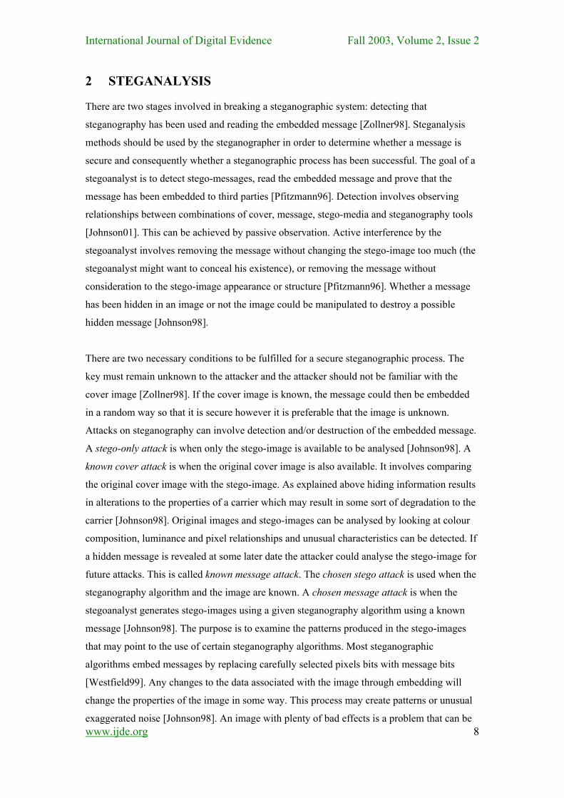
Figure 4 : Assignment function of replacement colours; colours that have an even index in the sorted palette become black, the rest becomes white [Westfield99]
An embedding filter presents the values pixels yield when the extraction function is applied to
them. For example the embedding filter for EzStego replaces the original palette by a black
and white palette. The original palette is sorted by frequency. The palette is then sorted by
luminance. Every even position in the palette (0, 2, 4, 6, ….) is set to black and every uneven
position in the palette is set to white. [Westfield99]. The replacement palette is now reordered
into its original order. This is shown in Figure 4 above.
If numerous comparisons can be made between the cover images and the stego-images
patterns can begin to emerge [Johnson01]. At a later stage if the cover is not available the
www.ijde.org
9
International Journal of Digital Evidence Fall 2003, Volume 2, Issue 2 known signature will be sufficient to indicate a message and the tool used to embed it
[Johnson01]. Some of the methods of carrying out steganography produce characteristics that
act as signatures for that steganography method [Johnson98]. The image may not give away
the existence of stenography but the palette could. Therefore steganography can be detected
by examining the palette itself. In colour palettes the colours are ordered from most used to
least used. The changes between colour values rarely change in one-bit increments in an
unstegoed image. But this feature would be created by embedding in the LSBs during
steganography. Greyscale palettes do change in one bit increments but all the RGB values are
the same. In monochromatic images usually two of the RGB values are the same and the third
usually has a much stronger saturation of colour. Therefore there are expected patterns in
palettes which if adjusted could indicate the use of steganography. If an original image
contains 200 colours steganography could result in the formation of 400 colours which would
be too many to store in the palette. When the image is saved as an 8-bit image it will produce
a new palette with 256 colours and information hidden could be lost. This is prevented by
reducing the colours initially so that space is available for new colours to be created. Adjacent
colours are added which are very close to the original. A stego-image is produced which is
very close to the original cover image [Brown94]. Reducing the colours in the palette and
creating new colours resulting from changing the LSBs of existing colours will results in
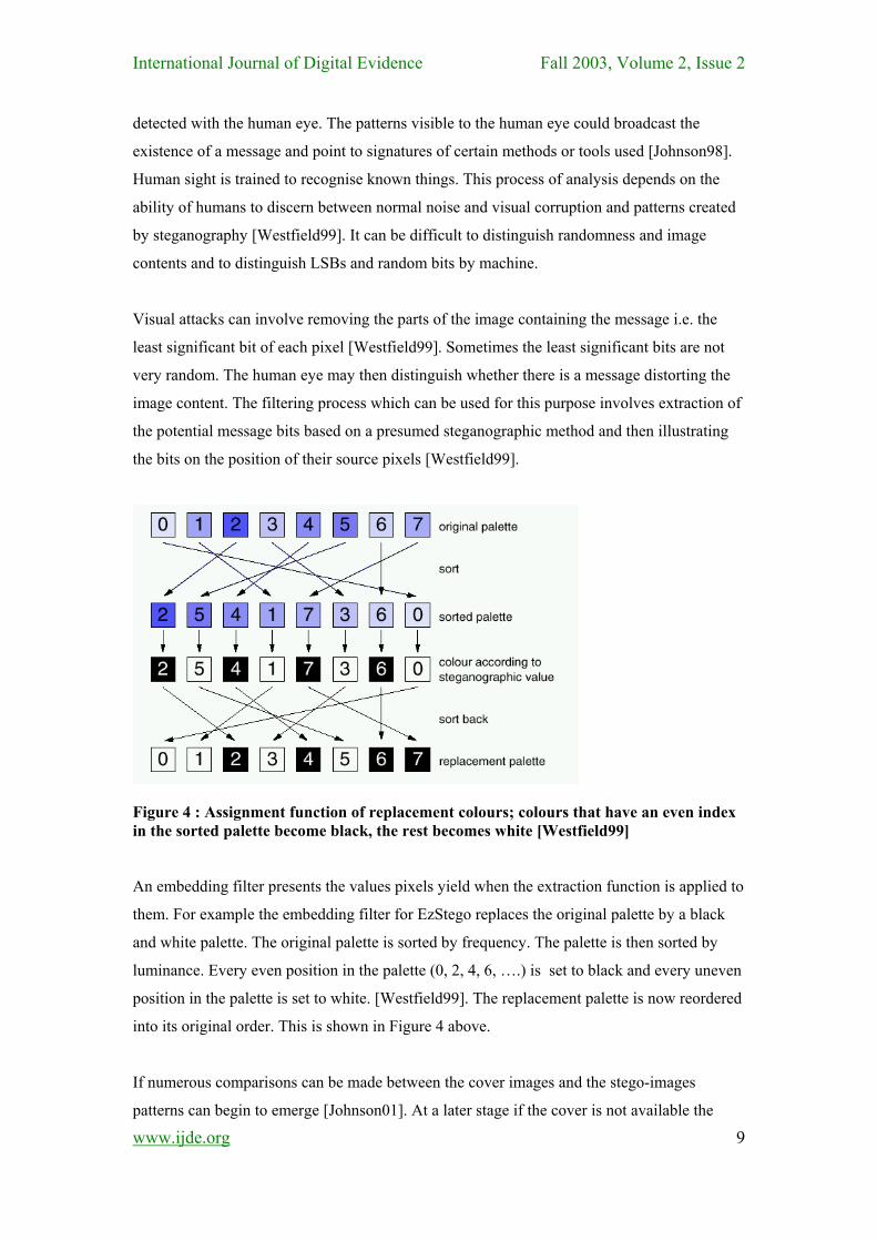
blocks of similar colours differing by one bit in the palette. This is shown in figure 2.14. The
palette on the right has blocks of similar colours produced by the creation of new colours by
adjustment of the LSBs. A unique pattern has been created in the palette.
Figure 5 : Cover (left) and Stego-Image Palette (right) after S-Tools [Johnson98]
Using a steganography method where pointers to the palette are changed may increase noise
because adjacent colours in the image become very different after the message has been
embedded [Johnson98]. This is alleviated by the use of greyscale images [Johnson98]. A
www.ijde.org
10
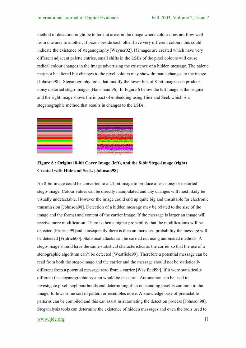
International Journal of Digital Evidence Fall 2003, Volume 2, Issue 2 method of detection might be to look at areas in the image where colour does not flow well
from one area to another. If pixels beside each other have very different colours this could
indicate the existence of steganography [Wayner02]. If images are created which have very
different adjacent palette entries, small shifts in the LSBs of the pixel colours will cause
radical colour changes in the image advertising the existence of a hidden message. The palette
may not be altered but changes to the pixel colours may show dramatic changes to the image
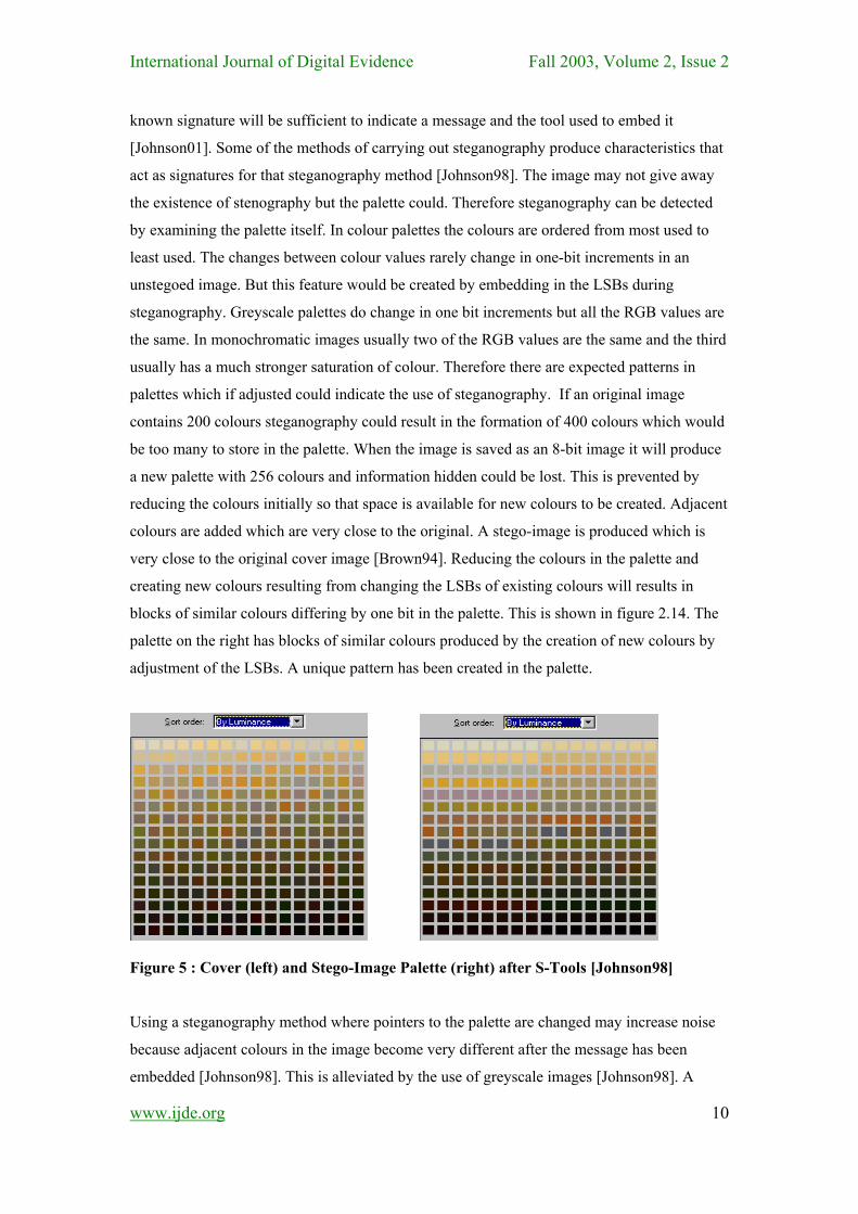
[Johnson98]. Steganography tools that modify the lower bits of 8-bit images can produce
noisy distorted stego-images [Hansmann96]. In Figure 6 below the left image is the original
and the right image shows the impact of embedding using Hide and Seek which is a
steganographic method that results in changes to the LSBs.
Figure 6 : Original 8-bit Cover Image (left), and the 8-bit Stego-Image (right)
Created with Hide and Seek. [Johnson98]
An 8-bit image could be converted to a 24-bit image to produce a less noisy or distorted
stego-image. Colour values can be directly manipulated and any changes will most likely be
visually undetectable. However the image could end up quite big and unsuitable for electronic
transmission [Johnson98]. Detection of a hidden message may be related to the size of the
image and the format and content of the carrier image. If the message is larger an image will
receive more modification. There is then a higher probability that the modifications will be
detected [Fridrich99]and consequently there is then an increased probability the message will
be detected [Fridrich00]. Statistical attacks can be carried out using automated methods. A
stego-image should have the same statistical characteristics as the carrier so that the use of a
stenographic algorithm can’t be detected [Westfield99]. Therefore a potential message can be
read from both the stego-image and the carrier and the message should not be statistically
different from a potential message read from a carrier [Westfield99]. If it were statistically
different the steganographic system would be insecure. Automation can be used to
investigate pixel neighbourhoods and determining if an outstanding pixel is common to the
image, follows some sort of pattern or resembles noise. A knowledge base of predictable
patterns can be compiled and this can assist in automating the detection process [Johnson98].
Steganalysis tools can determine the existence of hidden messages and even the tools used to
www.ijde.org
11
International Journal of Digital Evidence Fall 2003, Volume 2, Issue 2 embed them. A person wishing to detect someone else's stegoed images may analyse the type
of equipment being used to create the image such as a scanner or digital camera [Fridrich99].
A set of statistical measures could be determined which satisfy all of the images produced by
this piece of equipment and consequently statistical fingerprints could be determined caused
by the presence of a hidden message [Fridrich00].
In order to prevent detection steganographic and cryptographic keys can be used. A
steganographic key controls embedding and extracting of the message. The key could scatter
the message randomly over the carrier. A cryptographic key is used to encrypt a message
before embedding. Therefore even when the message is detected it can't be read. In the case
of bitwise methods destruction of the embedded message is fairly easy because the LSBs of
the images can be changed with compression. The image may be converted to lossy
compression format such as JPEG. JPEG images which have been processed with Jpeg-Jsteg
can be recompressed and this will destroy the message embedded in the DCT coefficients
because they will be recalculated [Johnson98].
A series of tests were carried out by Johnson to distort embedded data. The purpose was to
evaluate the robustness of bit-wise and transform tools [Johnson98]. The object of the tests
was to show what the techniques will withstand and what are some common vulnerabilities.
Images tested included digital photographs (24-bit or 8-bit greyscale JPEG and 24-bit BMP),
clip art (8-bit GIF) and digital art (24-bit BMP or JPEG, 8-bit BMP or GIF). To determine
robustness images were manipulated following embedding with a number of image
processing techniques: converting between lossless and lossy formats, converting between bit
densities, blurring, smoothing, adding noise, removing noise, sharpening, edge enhancement,
masking, rotating, scaling, re-sampling, warping, converting from digital to analog and back
(printing and scanning), mirroring, flipping, adding bitwise messages, adding transform
messages and applying the unZign and StirMark tools to test the robustness of watermarking
software. Tests were also carried out to determine the smallest size of image that can be used.
The tests were used to alter the information to such a point that it could not be retrieved again.
The message was then checked.
Conversion to compressed JPEG images or minor processing disables the bit wise tools.
Tools that relied on bit wise methods to hide the data could not recover any of the messages.
The transform tools did survive several of the image processing tests but failed when
combinations of image processes were carried out on them. These tests showed that the
transform methods are in fact more robust.
www.ijde.org
12
International Journal of Digital Evidence Fall 2003, Volume 2, Issue 2
3 IMAGE ANALYSIS Having carried out a review of steganographic and cryptographic methods it has been found
that one of the main methods typically used for steganography involves the process of hiding
a message in image pixels. Images are the most widespread carrier medium used. There are
various ways of doing this. In some methods the purpose is to minimize changes to the image
and in some the purpose is to store the message in a random way so as to make it more
difficult to detect. In some methods more information can be stored by using more than one
bit of the colours representing the pixels. This allows more information to be stored but also
results in the formation of more new colours and the need to use an image that is comprised
of less colours to start with. In some methods the process of storing information can result in
the production of new colours in the image and in some methods the existing colours only are
used. Some methods involve the use of a key. These different characteristics may be used
individually or combined to produce similar systems to many of those currently being used.
The aim of this study is to produce a system containing different steganographic methods and
to examine the strengths and weaknesses of those methods. The system to be produced will
also contain an option to encrypt the message before it is embedded.
While steganography can be carried out on any digital media it is reasonable for the purposes
of cross comparing methods to implement these methods on a common media type. The
chosen media for this system are GIF images. GIF images have been chosen because as they
are widely used in web pages, are recognised by all browsers and they are easily distributable
which ensures that they lend themselves to this type of activity without drawing attention to
themselves. Audio and video carriers require more intensive processing to hide data in them
as the files the carrier is stored in tend to be larger. BMP files have a very large number of
colours, which has advantages from a steganography point of view, but their corresponding
size makes them unsuitable for distribution across a web type medium. It has also been found
that the compression / decompression algorithm causes problems for steganography. GIF
undergoes lossless compression. The advantage of lossless compression is that the original
digital image is reproduced exactly and therefore the original arrangement of bits making up
the image is maintained. The LZW technique must normally be paid for however the software
is included in Java so that working on GIF programs in Java does not require any payment.
Images saved in JPEG use lossy compression in which the image is not reconstructed in
exactly the same way as the original. Space is saved in storing the image however some of the
bits and hence some of the data can be lost. JPEG files are sensitive to small changes in the
image data, which results in less capacity for holding a message9. It raises less suspicion than
www.ijde.org
13
International Journal of Digital Evidence Fall 2003, Volume 2, Issue 2 for example a BMP format11. Many steganograhy packages use GIF images including Hide
and Seek, S-Tools, GifShuffle, EzStego, and the method developed by Fridrich. A GIF image
has a restricted number of colours. The maximum number it can have is 256. GIF is a bitmap
image. Bitmap is a system in which an image is described as a bit pattern or series of numbers
that gives the shade or colour of each pixel. Greyscale GIF images, have pixel values from 0
to 255 which represent the intensity of the colour and do not refer to a palette2. Therefore the
purpose of this study is to develop a package which will carry out steganography by hiding a
text message in a GIF image carrier. As many of the methods which carry out steganography
use the process of hiding the message in image pixels this system will focus on hiding the
message in the least significant bits or parity bits of the colours in the pixels of an image. It is
proposed to develop and evaluate the following methods explained below. The names of the
methods are used to distinguish between the different steganographic processes that will be
carried out.
3.1 STEGO ONE BIT
When images are used as the carrier in steganography they are generally manipulated by
changing one or more of the bits of the byte or bytes that make up the pixels of an image. The
message can be stored in the LSB of one colour of the RGB value or in the parity bit of the
entire RGB value. Hide and Seek uses GIF images and the lower order bit of each pixel. One
of the methods for S-Tools involves changing the least significant bit of each of the three
colours in a pixel in a 24-bit image. Changing the LSB will only change the integer value of
the byte by one. This will not noticeable alter the visual appearance of a colour and hence the
image itself. Changing a more significant bit would cause a proportionately greater change in
the visual appearance of a colour. The main objective of steganography is to pass a message
to a receiver without an intruder even knowing that a message is being passed which means
that there should be no discernable change to the carrier. This is the first method to be tested
and will involve encoding some of the basic processes required for later steganographic
methods to be tested also. It will involve changing the LSB of one of the colours making up
the RGB value of the pixel. This should have very little effect on the appearance of the image.
This process will most likely result in the formation of new colours for the palette. Therefore
the image used must have a palette size of 128 pixels or less. This will allow for a doubling of
the colours in the palette (the creation of a new colour for every existing colour in the palette)
which is the maximum number of colours that could be produced by this method. It may be
found that if the palette is ordered by luminance that there will be pairs of very similar
colours. How noticeable that is depends on the colour profile used in the image to start with.
Practical methods should allow for the use of the full image size, thus the amount of data that
www.ijde.org
14
International Journal of Digital Evidence Fall 2003, Volume 2, Issue 2 can be hidden is proportionate to the number of pixels in the image rather than to the colours
in the palette. The only restriction is then the size of the image. Using the image data for
embedding is less restrictive on capacity compared to another method where data is stored in
the palette itself. Using a 128 palette image should not result in too much distortion to the
original image.
3.2 STEGO TWO BITS
Using this method two LSBs of one of the colours in the RGB value of the pixels will be used
to store message bits in the image. This will involve using a palette with a maximum of 64
colours allowing for the production of a possible 192 new colours,i.e. three new colours for
each existing colour. Less colour will be available to represent the starting image and hence it
will be more degraded than the image used in the method Stego One Bit. The advantage of
this method is that twice as much information can be stored here than in the previous method.
This method could instead have used the LSB of two colours in the RGB value which would
have resulted in the same amount of storage space. The starting image would still have to
have a palette containing 68 colours.
3.3 STEGO THREE BITS
Using this method three LSBs of one of the colours in the RGB value of the pixels will be
used to store message bits. This will involve using a palette with a maximum of only 32
colours allowing for the production of a possible 224 new colours, three new colours for
every existing colour in the image. The data hiding capacity is 3 times the storage capacity of
Stego One Bit but the image will be even more distorted than if a 128 colour palette was used.
3.4 STEGO FOUR BITS
Using this method four LSBs of one of the colours in the RGB value of the pixels will be used
to store message bits. This will involve using a palette with a maximum of only 16 colours
allowing for the production of a possible 240 new colours. This is the smallest palette that
could be used for an image using Jasc Paint Shop Pro. The colours are now very restricted but
an area of one particular colour in the image may have 16 variations distributed through it
which could result in a certain amount of texture mitigating the effects of such a restricted
palette.
3.5 STEGO COLOUR CYCLE
www.ijde.org
15
In order to make the detection of the hidden data more difficult it was decided to cycle
through the colour values in each of the pixels in which to store the data. This also means that
the same colour was not constantly being changed. For example the first data bit could be
International Journal of Digital Evidence Fall 2003, Volume 2, Issue 2 stored in the LSB of the blue value of the pixel, the second data bit in the red value and the
third data bit in the green value, The alpha value will be skipped and the next colour used will
be blue again. This is because changing the alpha value which is generally 255 would look
too suspicious unless the image used contained different transparency levels.
3.6 STEGO1BITPRNG
A pseudo random number generator can be used to choose random pixels in which to embed
the message. This will make the message bits more difficult to find and hopefully reduce the
existence of patterns in the image. Most importantly it means that if a cracker removed the
LSBs from one of the colours and tried to read them it would make no sense as they would
not be in order. A pseudo random number generator will be created and will be used to select
the pixels in which to hide the data. Data will then be hidden in the LSB of the blue value. If
the message is much smaller than the capacity of the image a problem may occur whereby the
information will be packed into one part of the image for example the top half. This is solved
by using a PRNG which will spread the message all over the image. Hide and Seek arranges it
so that the message bits will not be beside one another but instead randomly dispersed
throughout the image. Hence the noise will also be randomly distributed. A user chosen key
can be inserted into a pseudo random number generator which will determine a sequence of
random numbers. These numbers will indicate the pixels in the image where the least
significant bit is to be changed. This makes the system more secure because the reader of the
message must know the key in order to determine in which bytes the message bits are hidden.
The key must remain unknown to the attacker. If the cover image was known to the attacker,
embedding the message in a random way would improve its security.
3.7 STEGOFRIDRICH
EzStego encodes in the parity bit of indices of a GIF image. Fridrichs newer method also
involves manipulating existing colours in the palette. EzStego however firstly orders the
palette by luminance so that similar colours are beside one another. But Fridrichs method
involves pairing up all the colours in the palette so that the distance between the two colours
in each of the pairs is minimized. This method searches for the closest colour to the colour of
the pixel which has the correct parity for the bit to be hidden. The message is hidden in the
parity bit of the RGB values of close colours. For the colour of each pixel into which a
message bit is to be embedded the closest colours in the palette are searched until a palette
entry is found with the desired parity bit. This technique does not change the palette in any
way either by ordering it or by increasing the colours present in it. The parity bits of palette
entries of real images are randomly distributed therefore using this method it is never
www.ijde.org
16
International Journal of Digital Evidence Fall 2003, Volume 2, Issue 2 necessary to depart from the original colour too much. This avoids the problem of
occasionally having to make large changes in colour which might indicate that a message has
been hidden. Fridrich claims that his/her method of pseudo randomly changing the LSB of a
pixel by locating the closest pixel colour in the palette rather than adjusting the palette as with
EzStego produces approximately four times less distortion to the carrier image. Fridrich finds
the distance between colours whereas EzStego orders the palette by luminance. This is the
final steganography method to be encoded and evaluated. It is based on the method of
Fridrich but instead of searching for the closest colour each time a bit is to be hidden in a
pixel the closest colour to each colour in the palette with the opposite parity bit is initially
chosen. This reduces the problem of having to search through the palette each time a bit is to
be hidden. The pixels in which to hide the message are also pseudo randomly chosen in this
study a technique which Fridrich also uses.
3.8 CRYPTOGRAPHY – KNAPSACK
An encryption method will be investigated and will be provided as one of the final options for
the user. The purpose here is not to use or develop a secure cryptographic method but to use a
relatively simple method which contains a key in order to more randomly distribute the
message over the image. Knapsack was the first algorithm for generalized public key
encryption. Unfortunately it was found to be insecure. The idea behind Knapsack is that,
given a pile of items each having different weights it is possible to put some of them into a
Knapsack so that the Knapsack weighs a given amount. Given a set of values M1, M2, M3,
……Mn and a sum S the values of bi are computed so that S = b1M1 + b2M2 + b3M3 +
….bnMn. The values of bi can be either 0 or 1. 1 means that the value is in the sack 0 means
that it is not. This method has a public key and a private key. The private key is a super-
increasing sequence of numbers. A series of bits related to the plaintext are compared with the
key. Values in the key which have a 1 opposite them are added to the sum S i.e. the total
weight. A series of numbers generated in this manner builds up and this becomes the
encrypted code. A public key is also used. All of the values in the super-increasing sequence
are multiplied by a number n. mod m. The modulus must be a number greater than the sum of
all the values in the super-increasing sequence. n the multiplier should have no factors in
common with m. The sequence of numbers produced is the public key.
4 STEGANOGRAPHY SYSTEM
The best types of images to use are black and white greyscale or natural photographs with 24
bits per pixel which have been scanned in. The redundancy of the data helps to hide the
www.ijde.org
17
International Journal of Digital Evidence Fall 2003, Volume 2, Issue 2 presence of a secret message. A cover image should contain some randomness. It should
contain some natural uncertainty or noise. Hiding information may introduce enough visible
noise to raise suspicion. Therefore the carrier or cover image must be carefully selected. Once
it has been used the image should not be used again and should be destroyed. A familiar
image should not be used so it is better for the steganographer to create his / her own images.
Some software displays the image before and after data is hidden. This will also be done here.
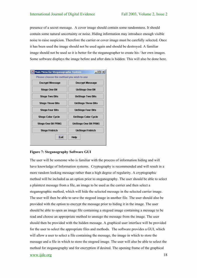
Figure 7: Steganography Software GUI
The user will be someone who is familiar with the process of information hiding and will
have knowledge of Information systems. Cryptography is recommended and will result in a
more random looking message rather than a high degree of regularity. A cryptographic
method will be included as an option prior to steganography. The user should be able to select
a plaintext message from a file, an image to be used as the carrier and then select a
steganographic method, which will hide the selected message in the selected carrier image.
The user will then be able to save the stegoed image in another file. The user should also be
provided with the option to encrypt the message prior to hiding it in the image. The user
should be able to open an image file containing a stegoed image containing a message to be
read and choose an appropriate method to unstego the message from the image. The user
should then be provided with the hidden message. A graphical user interface will be provided
for the user to select the appropriate files and methods. The software provides a GUI, which
will allow a user to select a file containing the message, the image in which to store the
message and a file in which to store the stegoed image. The user will also be able to select the
method for steganography and for encryption if desired. The opening frame of the graphical
www.ijde.org
18
International Journal of Digital Evidence Fall 2003, Volume 2, Issue 2 user interface which is shown in Figure 7 contains a series of buttons one, to encrypt a
message, one to decrypt a message, one for each of the seven steganography methods and one
for each of the seven methods to reverse the steganography process and finally a Help button
and an Exit button.
5 EVALUATION
The next and possibly the most important stage is the evaluation of the steganographic
methods implemented above. Based on the literature survey a number of evaluation methods
have been chosen. The steganographic methods will be evaluated by passive observation of
the stegoed image and by comparing the stegoed image with similar unstegoed images.
Similar here means that they are not the same but have the same content and lighting.
Evaluators will look for patterns or unusual exaggerated noise. The patterns visible to the
human eye could broadcast the existence of a message. Another type of analysis involves
comparing the original cover image with the stego-image in a number of ways. The palette
will be examined. A reduced palette or noticeable pairs of colours in the palette will be looked
for. A palette containing only 128 different colours should be easy to detect. The effects of
embedding larger and smaller messages will be evaluated. Colour and greyscale images will
be compared. Images were created for this study using a digital camera. The content for the
images chosen was natural unsymmetrical environments with fairly busy subject matter.
Smooth continuous areas are minimized and the images contain quite a high level of detail.
In order to minimize the number of different variables which had to be taken in account in the
evaluation process it has been decided not to encrypt the messages hidden in the stegoed
images. Thus the Knapsack encryption algorithm has been implemented but is not included in
the evaluation process.
5.1 METHODS OF EVALUATION
Four distinct but complementary methods of evaluation will be used. These are:
Pattern Analysis of Image Pixels: This detection method is based on looking for
patterns in the bits that make up the pixel colours. For example if methods hide messages
in the least significant bits of pixels then looking for patterns in the least significant bits
of pixels is an easy way to detect the existence of messages. There are many variations of
this message hiding technique such as hiding the message bit in the least significant bit of
either the red, green or blue value of the colour or the parity bit of the pixel. This analysis
www.ijde.org
19
International Journal of Digital Evidence Fall 2003, Volume 2, Issue 2
will be carried out based on the literature survey rather than visual inspection of the
images. The objective is to determine which of the methods being studied are vulnerable
to this method of analysis and how vulnerable they are.
Pattern Analysis of Image Palette: This detection method is based on looking for
patterns in the images palette. For example some steganography methods require an
image with a reduced number of colours. The steganography methods then create new
colours that are almost identical to the existing ones but have different least significant
bits or parities. By ordering the palette by luminance such pairings may be visible. The
fewer original colours the steganography method allows the more obvious it should be in
the palette. A colour reduced original image with a large message may have up to 256
colours in the palette half of which will be almost identical to the other half. With a small
message the number of new colours added to the original reduced set will be much
smaller. In practice however the number of new colours created by the steganography
process must be a maximum of 256 (GIF images) but is otherwise random. Some
methods do not however use colour-reduced images and rely entirely on existing colours.
For this part of the analysis the palette of a greyscale image was compared 7 times, once
for each different type of steganography method. Palettes will be examined for colour
images which have had various forms of steganography carried out on them. In each case
the palette will be ordered by luminance to make it more coherent. Of course when the
palette is not ordered by luminance, patterns in the palette are much harder to see. It is
assumed however that somebody attempting to carry out steganalysis would order the
palette to make their job easier. The palette from stegoed images will be compared with
the palette of the original 256 colour image and the palette of a reduced colour unstegoed
image to see how much the palette has changed. Finally the palette will be examined to
look at how it changes when hiding long and short messages.
Visual Inspection of the Image: This analysis method is based on evaluation
through visual inspection of the image by independent evaluators. In all cases, the
steganographic methods create a degree of distortion in the image, due to the reduction in
the number of colours or the mixing and matching of existing colours. The question is
how vulnerable are different techniques to detection through visual inspection of the
image for tell tale distortion. An evaluator should typically look for a grainy structure or
appearance; too few colours causing colour blocks and a lack of texture; lack of
continuity in the colour and subtle distortions of any type
www.ijde.org
20
International Journal of Digital Evidence Fall 2003, Volume 2, Issue 2
For this evaluation 13 independent evaluators were used. All of the evaluators had a
knowledge of computing and an understanding of how images are formed. However they
did not have detailed knowledge of how steganography works. Each evaluator was
provided with a brief description of steganography and told what features to look for in a
stegoed picture. They were provided with a menu of folders and images and asked to
identify the stegoed images (size 300 x 200 pixels). Each evaluator was presented with a
suite of 18 folders. Each folder contained 6 images which were similar in content and
lighting but were not identical. Each folder contained one stegoed image and five 256
colour unstegoed images. The first block of 6 folders thus had 6 stegoed images one for
each steganography method under inspection (Stego1Bit, Stego2Bits, Stego3Bits,
StegoColorCycle, StegoPRNG and StegoFridrich. Stego4Bits is not being evaluated here
as it is clearly vulnerable to almost every type of inspection). Three sets of 6 folders were
evaluated, a set of greyscale pictures of trees, an identical set of colour pictures of trees
and a set of colour pictures of flowers.
Low Level Visual Inspection of Image Pixels: This detection method is based on
carrying out a detailed inspection of selected sections of an image at a high degree of
magnification to determine whether anomalous patterns become apparent. As an
inspection technique this might be problematical if the original cover image is not
available for comparison. Under normal circumstances a person seeking to hide data in an
image would be expected to use an image they have created themselves rather than a
generally known image and therefore the original cover image would not be available for
comparison with the stegoed image using this inspection method. The tell tale distortions
which would typically be looked for include a lack of continuity where continuity is
expected (Fridrich method) and a lack of texture where texture is expected (colour
reduction).
The following shows the evaluation results for the evaluation methods described above. 5.2 PATTERN ANALYSIS OF IMAGE PIXELS From the literature survey it is clear that Stego1Bit has a very high degree of vulnerability to
steganalysis. This is due to the repeating patterns that are created in the least significant bit of
the chosen colour. Thus this method is very vulnerable to detection from automated
steganalysis methods. A variety of techniques of varying sophistication are used to combat
www.ijde.org
21

International Journal of Digital Evidence Fall 2003, Volume 2, Issue 2 this weakness. Stego2Bits, Stego3Bits, Stego4Bits and StegoColorCycle all break up the least
significant bit pattern in different ways but are all extremely well known methods of hiding
data. Therefore the patterns they create when attempting to hide the least significant bit
pattern are only slightly more difficult to detect. For a method to be truly resilient against
steganalysis using pattern searches bits must be hidden in an apparently random way. The
pattern by which they are hidden must be reproducible but not easily reproducible. Thus the
key based pseudo random number generation technique used by the Stego1BitPRNG method
and the StegoFridrich method make these techniques highly resistant to this form of
steganalysis.
5.3 PATTERN ANALYSIS OF IMAGE PALETTE The pattern analysis of the image palettes will be carried out in two stages. First greyscale
palettes will be examined and then colour palettes will be examined. In both cases the reduced
unstegoed palettes will be shown and then the stegoed versions of these reduced palettes will
be shown. A discussion of the results will also be included. When colours or grey levels are
reduced for colour or greyscale images using colour reduction methods such as nearest colour
and error diffusion, although the palette starts out with up to 256 colours or grey levels and
for example 128 are required, the actual colour reduction level can be significantly less than
the 128 colours or grey levels requested. The actual number of colours left depends on the
original image used when reducing the colours or levels using the software Paint Shop Pro.
Therefore although a reduction to 128 colours or grey levels is all that is required the images
tested contained somewhat less than 128 colours / grey levels. Due to the manner in which
the colour reduction is carried out by Paint Shop Pro it can take a bit of experimentation to get
approximately the required number of colours / grey levels. Greyscale images seem to be
more prone to overshooting the target when reducing colours than colour images are. The
palettes have all been ordered by luminance in order to simplify the analysis of the contents.
5.4 GREYSCALE IMAGES
www.ijde.org
22
All of the steganography methods tested except StegoFridrich require a reduced palette to
allow for the creation of new colours. The code used in this study embeds data in the least
significant bits of red, green or blue values or a combination of these in all the methods tested
except for StegoFridrich. Therefore although greyscale values are being examined in the first
set of images, the red, green, blue values of pixel colours are still the location where the
message bits are embedded. Shown below is a series of palettes for one particular image, first
in greyscale and then in colour. Each palette shown is for the same image but the image in
each case is composed of different numbers of greyscale levels or colours. Stego1Bit and
International Journal of Digital Evidence Fall 2003, Volume 2, Issue 2 Stego1BitPRNG require an image with a palette which is made up of a maximum of 128
colours. Stego2Bits and StegoColorCycle require an image with a palette with a maximum of
64 colours. Stego3Bits needs an image with a maximum of 32 colours and Stego4Bits
requires an image with a palette with a maximum of 16 colours. StegoFridrich does not
require any reduction in the number of colours in the image, as the method does not involve
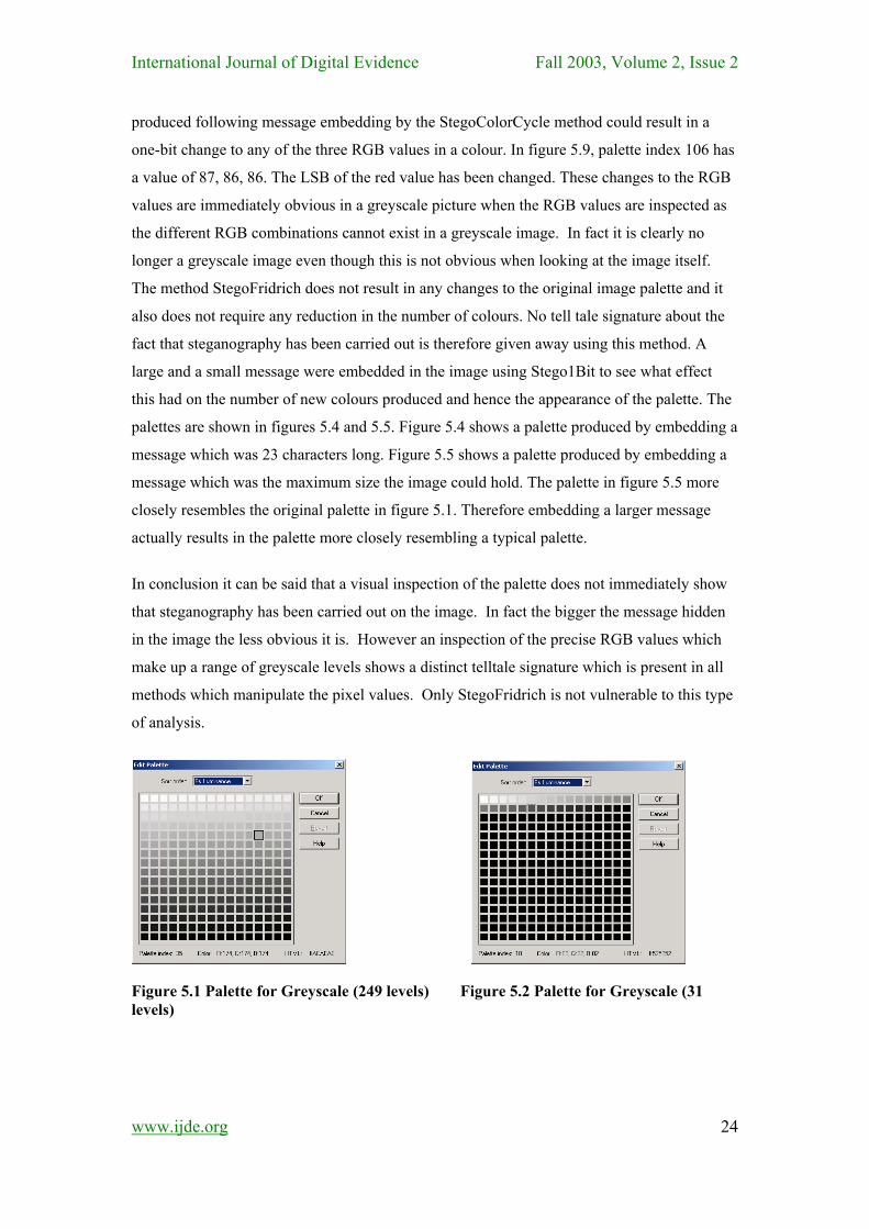
the creation of any new colours. Figure 5.1 shows the palette from the original greyscale
image containing 249 levels of greyscale. Figure 5.2 and 5.3 show palettes for the same image
whose colours have been reduced so that the image can be used to embed a message. Figure
5.1 is a typical greyscale palette but figure 5.2 and 5.3 clearly show a much-reduced range of
greyscale levels. However the interesting thing discovered during this analysis is that because
new greyscale levels are being created by the steganography process the palette fills up with
or at least increases its number of greyscale levels to account for the new levels created. This
results in the palettes looking much more similar to the original. Someone trying to carry out
steganalysis won’t see the original reduced palette, but the palette they will see will be very
similar to a typical greyscale palette. The slight variations between original colours and newly
created colours are not visually very discernible in these palettes as there is in any case a very
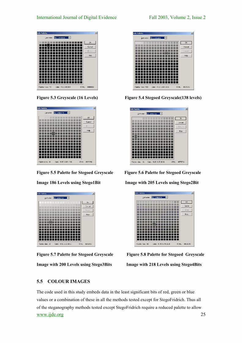
gradual change between greyscale levels on a typical palette. The stegoed image palettes for
the remaining steganography methods are also shown below in figures 5.4 to 5.8. Although
they range from 138 to 218 greyscale levels they do not show the dramatic greyscale level
reduction visible in the reduced palettes of the unstegoed images. Therefore creating an
increased number of new levels of greyscale as a result of stegoing an image serves to make
the palette look more like a typical palette which has somewhere close to 256 levels of
greyscale.
There is however one giveaway factor which should be noted. If the RGB values are
examined using for example the software Paint Shop Pro on a typical palette for greyscale the
three RGB values are all the same for a given grey level. This was found for the palettes in
figures 5.1, 5.2 and 5.3 below. However in all the stegoed images palettes, excluding
StegoFridrich, when a pixel in the palette is passed over with the mouse the RGB values are
shown and in some cases they are not the same for each colour in the palette. In figure 5.4
which shows the palette produced for an image following steganography using the Stego1Bit
method, the blue value in the palette in some cases differs by one bit. The colours in the
palette show that pixel index 103 is 87, 87, 86. The LSB of the blue value has been changed.
In the palette for Stego2Bits the value for the blue part of the RGB value can change by
between 0 and 3 (the two least significant bits), using Stego3Bits it can change by between 0
and 7 and using Stego4Bits it can change by between 0 and 15. The palette for the image
www.ijde.org
23
International Journal of Digital Evidence Fall 2003, Volume 2, Issue 2 produced following message embedding by the StegoColorCycle method could result in a
one-bit change to any of the three RGB values in a colour. In figure 5.9, palette index 106 has
a value of 87, 86, 86. The LSB of the red value has been changed. These changes to the RGB
values are immediately obvious in a greyscale picture when the RGB values are inspected as
the different RGB combinations cannot exist in a greyscale image. In fact it is clearly no
longer a greyscale image even though this is not obvious when looking at the image itself.
The method StegoFridrich does not result in any changes to the original image palette and it
also does not require any reduction in the number of colours. No tell tale signature about the
fact that steganography has been carried out is therefore given away using this method. A
large and a small message were embedded in the image using Stego1Bit to see what effect
this had on the number of new colours produced and hence the appearance of the palette. The
palettes are shown in figures 5.4 and 5.5. Figure 5.4 shows a palette produced by embedding a
message which was 23 characters long. Figure 5.5 shows a palette produced by embedding a
message which was the maximum size the image could hold. The palette in figure 5.5 more
closely resembles the original palette in figure 5.1. Therefore embedding a larger message
actually results in the palette more closely resembling a typical palette.
In conclusion it can be said that a visual inspection of the palette does not immediately show
that steganography has been carried out on the image. In fact the bigger the message hidden
in the image the less obvious it is. However an inspection of the precise RGB values which
make up a range of greyscale levels shows a distinct telltale signature which is present in all
methods which manipulate the pixel values. Only StegoFridrich is not vulnerable to this type
of analysis.
Figure 5.1 Palette for Greyscale (249 levels) Figure 5.2 Palette for Greyscale (31 levels)
www.ijde.org
24
International Journal of Digital Evidence Fall 2003, Volume 2, Issue 2
Figure 5.3 Greyscale (16 Levels) Figure 5.4 Stegoed Greyscale(138 levels)
Figure 5.5 Palette for Stegoed Greyscale Figure 5.6 Palette for Stegoed Greyscale
Image 186 Levels using Stego1Bit Image with 205 Levels using Stego2Bit
Figure 5.7 Palette for Stegoed Greyscale Figure 5.8 Palette for Stegoed Greyscale
Image with 200 Levels using Stego3Bits Image with 218 Levels using Stego4Bits
5.5 COLOUR IMAGES The code used in this study embeds data in the least significant bits of red, green or blue
values or a combination of these in all the methods tested except for StegoFridrich. Thus all
of the steganography methods tested except StegoFridrich require a reduced palette to allow www.ijde.org
25
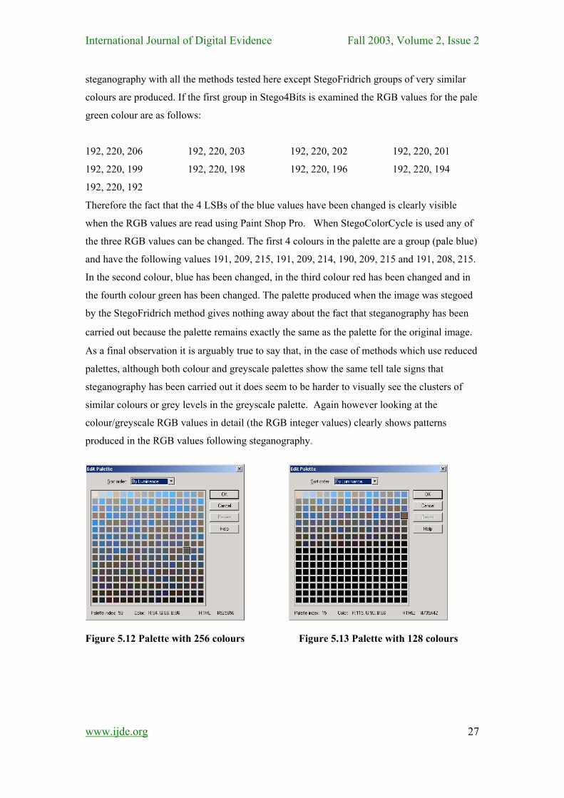
International Journal of Digital Evidence Fall 2003, Volume 2, Issue 2 for the creation of new colours in the palette. The first palette shown in figure 5.12 is a
palette for a colour image which is the same image whose palettes were examined above in
greyscale. It contains 256 colours. Two examples were taken of reduced palettes just to give a
representation of what the reduced palettes look like. It was felt unnecessary to display all the
reduced palettes. Figure 5.13 shows a palette whose colours have been reduced to 128. This is
required for the Stego1Bit and Stego1BitPRNG methods. Although it is obvious that about
half the possible colours are being used this does not mean that they were necessarily reduced
for stegoing, although it is a pointer. The key point is that if a steganographer uses their own
unique images the stegoanalyst should not have access to the original unstegoed image and
correspondingly will never see these reduced palettes. Figure 5.14 shows the palette used for
the Stego4Bits steganography method. It only has 16 different colours.
We stegoed images using Stego1Bit with a message less than the size of the image and a
message the capacity of the image. In their unordered form these palettes looked like any
other image palettes. But when they have been ordered by luminance a pattern is visible.
What it shows is that some of the colours are arranged in pairs of very similar colours. This
occurs because the LSB of some colours have been changed resulting in a very similar new
colour. This new colour may not be visible when examining the image but it is a new colour
and must be listed separately in the palette. This is a pointer to the occurrence of
steganography. The maximum size message has resulted in this case in the creation of extra
new colours. This fills up the unordered palette which tends to hide the fact that
steganography has occurred but as it also creates more pairings when the palette is ordered
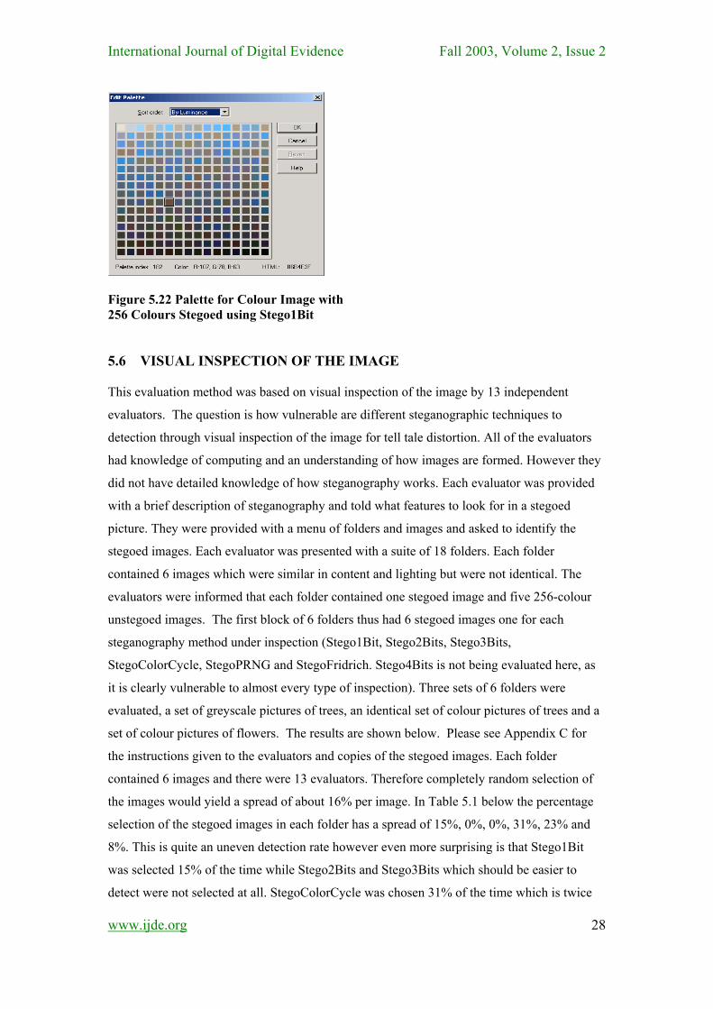
which does highlight the fact that steganography has been carried out. Figure 5.22 shows a
palette from an image produced by stegoing with Stego1Bit PRNG. Pairs of colours are
visible in the palette in the same way as they are visible in the palette for Stego1Bit. It does
not follow that because the palette is a pointer to steganography that the stegoanalyst will be
able to read the message from the image. In the case of Stego1BitPRNG the message bits are
pseudo randomly spread over the image pixels. Therefore the key to the pseudo random
number generator would need to be known as well as the algorithm. Unfortunately though if a
stegoanalyst is looking for stegoed images patterns in the palette will result in the image being
carefully analysed defeating the purpose of steganography which is to prevent anyone
knowing that a message is being sent at all. Unlike a greyscale image, if the RGB values are
examined using for example Paint Shop Pro software on a typical palette for a colour image
this time the three RGB values are not the same for a given colour unless it is a greyscale
colour. In a greyscale image they are the same. This is an advantage for colour images
because changing LSBs in therefore not as noticeable. However as discussed above following
www.ijde.org
26
International Journal of Digital Evidence Fall 2003, Volume 2, Issue 2 steganography with all the methods tested here except StegoFridrich groups of very similar
colours are produced. If the first group in Stego4Bits is examined the RGB values for the pale
green colour are as follows:
192, 220, 206 192, 220, 203 192, 220, 202 192, 220, 201
192, 220, 199 192, 220, 198 192, 220, 196 192, 220, 194
192, 220, 192
Therefore the fact that the 4 LSBs of the blue values have been changed is clearly visible
when the RGB values are read using Paint Shop Pro. When StegoColorCycle is used any of
the three RGB values can be changed. The first 4 colours in the palette are a group (pale blue)
and have the following values 191, 209, 215, 191, 209, 214, 190, 209, 215 and 191, 208, 215.
In the second colour, blue has been changed, in the third colour red has been changed and in
the fourth colour green has been changed. The palette produced when the image was stegoed
by the StegoFridrich method gives nothing away about the fact that steganography has been
carried out because the palette remains exactly the same as the palette for the original image. As a final observation it is arguably true to say that, in the case of methods which use reduced
palettes, although both colour and greyscale palettes show the same tell tale signs that
steganography has been carried out it does seem to be harder to visually see the clusters of
similar colours or grey levels in the greyscale palette. Again however looking at the
colour/greyscale RGB values in detail (the RGB integer values) clearly shows patterns
produced in the RGB values following steganography.
Figure 5.12 Palette with 256 colours Figure 5.13 Palette with 128 colours
www.ijde.org
27
International Journal of Digital Evidence Fall 2003, Volume 2, Issue 2
Figure 5.22 Palette for Colour Image with 256 Colours Stegoed using Stego1Bit 5.6 VISUAL INSPECTION OF THE IMAGE This evaluation method was based on visual inspection of the image by 13 independent
evaluators. The question is how vulnerable are different steganographic techniques to
detection through visual inspection of the image for tell tale distortion. All of the evaluators
had knowledge of computing and an understanding of how images are formed. However they
did not have detailed knowledge of how steganography works. Each evaluator was provided
with a brief description of steganography and told what features to look for in a stegoed
picture. They were provided with a menu of folders and images and asked to identify the
stegoed images. Each evaluator was presented with a suite of 18 folders. Each folder
contained 6 images which were similar in content and lighting but were not identical. The
evaluators were informed that each folder contained one stegoed image and five 256-colour
unstegoed images. The first block of 6 folders thus had 6 stegoed images one for each
steganography method under inspection (Stego1Bit, Stego2Bits, Stego3Bits,
StegoColorCycle, StegoPRNG and StegoFridrich. Stego4Bits is not being evaluated here, as
it is clearly vulnerable to almost every type of inspection). Three sets of 6 folders were
evaluated, a set of greyscale pictures of trees, an identical set of colour pictures of trees and a
set of colour pictures of flowers. The results are shown below. Please see Appendix C for
the instructions given to the evaluators and copies of the stegoed images. Each folder
contained 6 images and there were 13 evaluators. Therefore completely random selection of
the images would yield a spread of about 16% per image. In Table 5.1 below the percentage
selection of the stegoed images in each folder has a spread of 15%, 0%, 0%, 31%, 23% and
8%. This is quite an uneven detection rate however even more surprising is that Stego1Bit
was selected 15% of the time while Stego2Bits and Stego3Bits which should be easier to
detect were not selected at all. StegoColorCycle was chosen 31% of the time which is twice
www.ijde.org
28
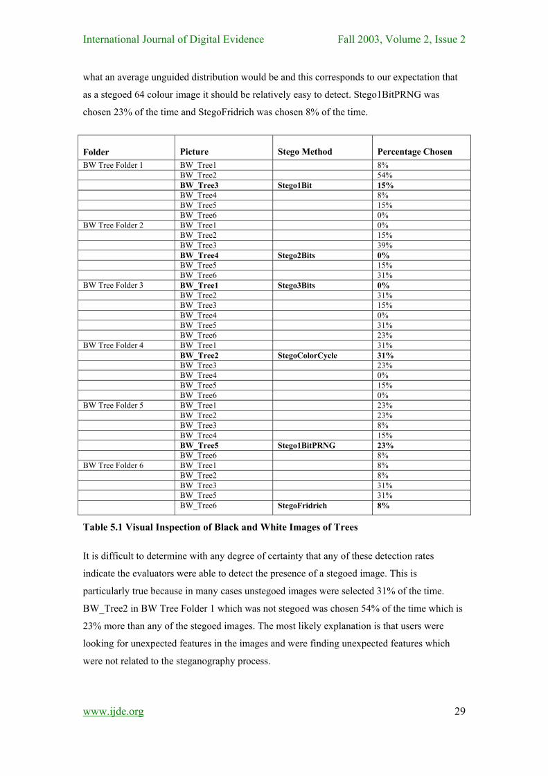
International Journal of Digital Evidence Fall 2003, Volume 2, Issue 2 what an average unguided distribution would be and this corresponds to our expectation that
as a stegoed 64 colour image it should be relatively easy to detect. Stego1BitPRNG was
chosen 23% of the time and StegoFridrich was chosen 8% of the time.
Folder Picture
Stego Method
Percentage Chosen
BW Tree Folder 1 BW_Tree1 8% BW_Tree2 54% BW_Tree3 Stego1Bit 15% BW_Tree4 8% BW_Tree5 15% BW_Tree6 0% BW Tree Folder 2 BW_Tree1 0% BW_Tree2 15% BW_Tree3 39% BW_Tree4 Stego2Bits 0% BW_Tree5 15% BW_Tree6 31% BW Tree Folder 3 BW_Tree1 Stego3Bits 0% BW_Tree2 31% BW_Tree3 15% BW_Tree4 0% BW_Tree5 31% BW_Tree6 23% BW Tree Folder 4 BW_Tree1 31% BW_Tree2 StegoColorCycle 31% BW_Tree3 23% BW_Tree4 0% BW_Tree5 15% BW_Tree6 0% BW Tree Folder 5 BW_Tree1 23% BW_Tree2 23% BW_Tree3 8% BW_Tree4 15% BW_Tree5 Stego1BitPRNG 23% BW_Tree6 8% BW Tree Folder 6 BW_Tree1 8% BW_Tree2 8% BW_Tree3 31% BW_Tree5 31% BW_Tree6 StegoFridrich 8%
Table 5.1 Visual Inspection of Black and White Images of Trees
It is difficult to determine with any degree of certainty that any of these detection rates
indicate the evaluators were able to detect the presence of a stegoed image. This is
particularly true because in many cases unstegoed images were selected 31% of the time.
BW_Tree2 in BW Tree Folder 1 which was not stegoed was chosen 54% of the time which is
23% more than any of the stegoed images. The most likely explanation is that users were
looking for unexpected features in the images and were finding unexpected features which
were not related to the steganography process.
www.ijde.org
29
International Journal of Digital Evidence Fall 2003, Volume 2, Issue 2
Folder Picture Stego Method Percentage Chosen Colour Tree Folder 1 Colour Tree1 15% Colour Tree2 Stego1BitPRNG 46%
Colour Tree3 8% Colour Tree4 8% Colour Tree5 15% Colour Tree6 8% Colour Tree Folder 2 Colour Tree1 15% Colour Tree2 23% Colour Tree3 8% Colour Tree4 Stego2Bits 39% Colour Tree5 15% Colour Tree6 0% Colour Tree Folder 3 Colour Tree1 0% Colour Tree2 15% Colour Tree3 8% Colour Tree4 8% Colour Tree5 8% Colour Tree6 Stego3Bits 62% Colour Tree Folder 4 Colour Tree1 StegoColorCycle 54% Colour Tree2 8% Colour Tree3 8% Colour Tree4 23% Colour Tree5 8% Colour Tree6 0% Colour Tree Folder 5 Colour Tree1 0% Colour Tree2 8% Colour Tree3 Stego1Bit 8% Colour Tree4 23% Colour Tree5 31% Colour Tree6 31% Colour Tree Folder 6 Colour Tree1 15% Colour Tree2 8% Colour Tree3 15% Colour Tree4 15% Colour Tree5 StegoFridrich 31% Colour Tree6 15%
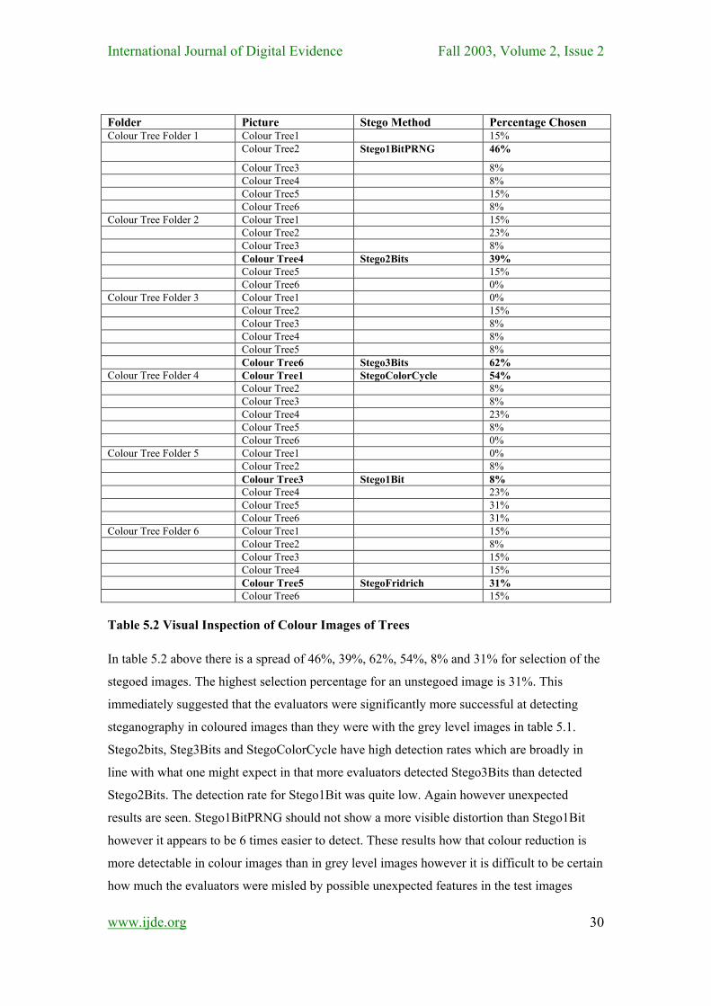
Table 5.2 Visual Inspection of Colour Images of Trees In table 5.2 above there is a spread of 46%, 39%, 62%, 54%, 8% and 31% for selection of the
stegoed images. The highest selection percentage for an unstegoed image is 31%. This
immediately suggested that the evaluators were significantly more successful at detecting
steganography in coloured images than they were with the grey level images in table 5.1.
Stego2bits, Steg3Bits and StegoColorCycle have high detection rates which are broadly in
line with what one might expect in that more evaluators detected Stego3Bits than detected
Stego2Bits. The detection rate for Stego1Bit was quite low. Again however unexpected
results are seen. Stego1BitPRNG should not show a more visible distortion than Stego1Bit
however it appears to be 6 times easier to detect. These results how that colour reduction is
more detectable in colour images than in grey level images however it is difficult to be certain
how much the evaluators were misled by possible unexpected features in the test images
www.ijde.org
30
International Journal of Digital Evidence Fall 2003, Volume 2, Issue 2 which were not related to steganography.
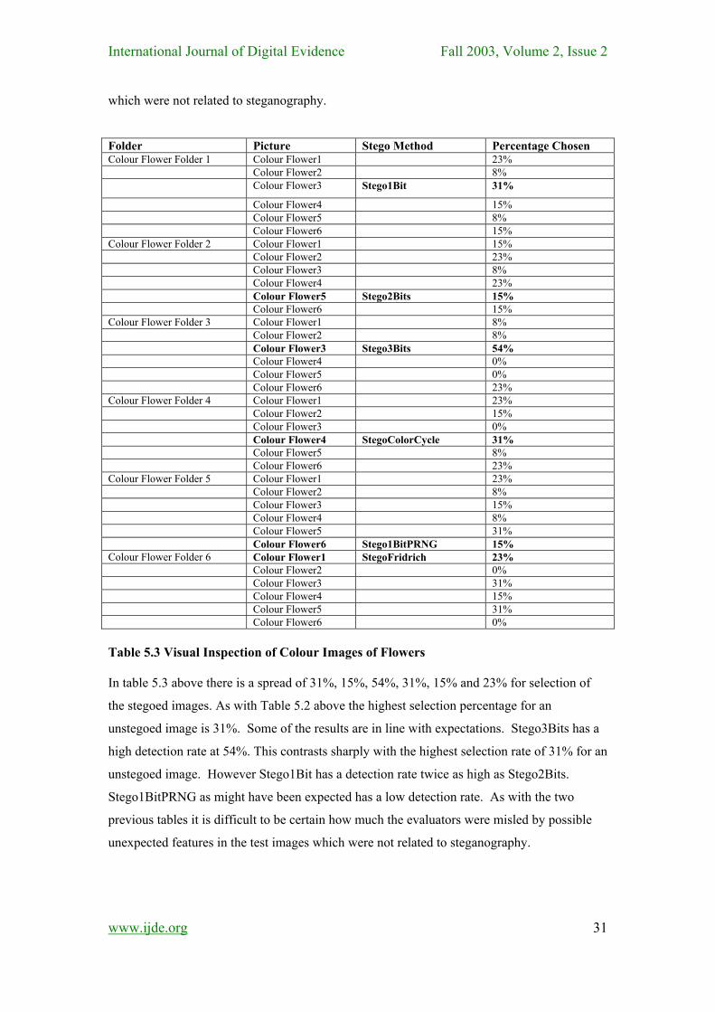
Folder Picture Stego Method Percentage Chosen Colour Flower Folder 1 Colour Flower1 23% Colour Flower2 8% Colour Flower3 Stego1Bit 31%
Colour Flower4 15% Colour Flower5 8% Colour Flower6 15% Colour Flower Folder 2 Colour Flower1 15% Colour Flower2 23% Colour Flower3 8% Colour Flower4 23% Colour Flower5 Stego2Bits 15% Colour Flower6 15% Colour Flower Folder 3 Colour Flower1 8% Colour Flower2 8% Colour Flower3 Stego3Bits 54% Colour Flower4 0% Colour Flower5 0% Colour Flower6 23% Colour Flower Folder 4 Colour Flower1 23% Colour Flower2 15% Colour Flower3 0% Colour Flower4 StegoColorCycle 31% Colour Flower5 8% Colour Flower6 23% Colour Flower Folder 5 Colour Flower1 23% Colour Flower2 8% Colour Flower3 15% Colour Flower4 8% Colour Flower5 31% Colour Flower6 Stego1BitPRNG 15% Colour Flower Folder 6 Colour Flower1 StegoFridrich 23% Colour Flower2 0% Colour Flower3 31% Colour Flower4 15% Colour Flower5 31% Colour Flower6 0% Table 5.3 Visual Inspection of Colour Images of Flowers In table 5.3 above there is a spread of 31%, 15%, 54%, 31%, 15% and 23% for selection of
the stegoed images. As with Table 5.2 above the highest selection percentage for an
unstegoed image is 31%. Some of the results are in line with expectations. Stego3Bits has a
high detection rate at 54%. This contrasts sharply with the highest selection rate of 31% for an
unstegoed image. However Stego1Bit has a detection rate twice as high as Stego2Bits.
Stego1BitPRNG as might have been expected has a low detection rate. As with the two
previous tables it is difficult to be certain how much the evaluators were misled by possible
unexpected features in the test images which were not related to steganography.
www.ijde.org
31
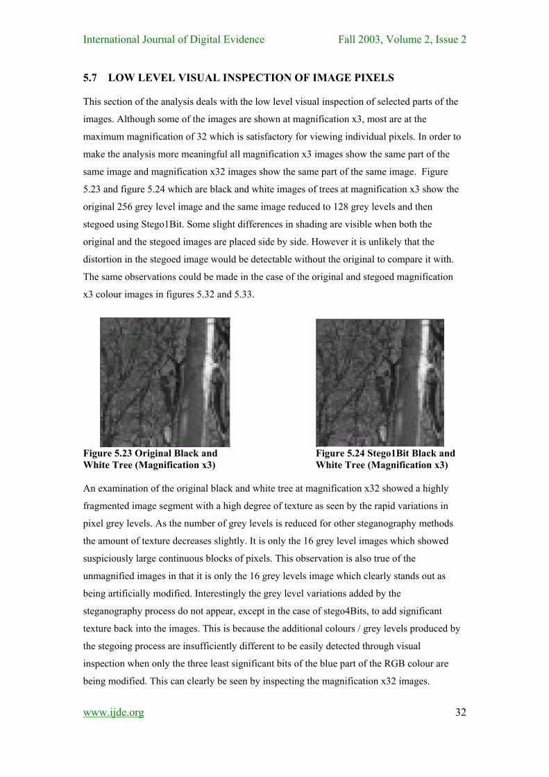
International Journal of Digital Evidence Fall 2003, Volume 2, Issue 2 5.7 LOW LEVEL VISUAL INSPECTION OF IMAGE PIXELS This section of the analysis deals with the low level visual inspection of selected parts of the
images. Although some of the images are shown at magnification x3, most are at the
maximum magnification of 32 which is satisfactory for viewing individual pixels. In order to
make the analysis more meaningful all magnification x3 images show the same part of the
same image and magnification x32 images show the same part of the same image. Figure
5.23 and figure 5.24 which are black and white images of trees at magnification x3 show the
original 256 grey level image and the same image reduced to 128 grey levels and then
stegoed using Stego1Bit. Some slight differences in shading are visible when both the
original and the stegoed images are placed side by side. However it is unlikely that the
distortion in the stegoed image would be detectable without the original to compare it with.
The same observations could be made in the case of the original and stegoed magnification
x3 colour images in figures 5.32 and 5.33.
Figure 5.23 Original Black and Figure 5.24 Stego1Bit Black and White Tree (Magnification x3) White Tree (Magnification x3) An examination of the original black and white tree at magnification x32 showed a highly
fragmented image segment with a high degree of texture as seen by the rapid variations in
pixel grey levels. As the number of grey levels is reduced for other steganography methods
the amount of texture decreases slightly. It is only the 16 grey level images which showed
suspiciously large continuous blocks of pixels. This observation is also true of the
unmagnified images in that it is only the 16 grey levels image which clearly stands out as
being artificially modified. Interestingly the grey level variations added by the
steganography process do not appear, except in the case of stego4Bits, to add significant
texture back into the images. This is because the additional colours / grey levels produced by
the stegoing process are insufficiently different to be easily detected through visual
inspection when only the three least significant bits of the blue part of the RGB colour are
being modified. This can clearly be seen by inspecting the magnification x32 images.
www.ijde.org
32
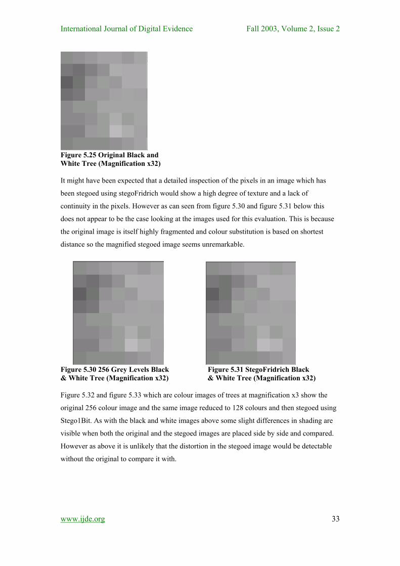
International Journal of Digital Evidence Fall 2003, Volume 2, Issue 2
Figure 5.25 Original Black and White Tree (Magnification x32) It might have been expected that a detailed inspection of the pixels in an image which has
been stegoed using stegoFridrich would show a high degree of texture and a lack of
continuity in the pixels. However as can seen from figure 5.30 and figure 5.31 below this
does not appear to be the case looking at the images used for this evaluation. This is because
the original image is itself highly fragmented and colour substitution is based on shortest
distance so the magnified stegoed image seems unremarkable.
Figure 5.30 256 Grey Levels Black Figure 5.31 StegoFridrich Black & White Tree (Magnification x32) & White Tree (Magnification x32) Figure 5.32 and figure 5.33 which are colour images of trees at magnification x3 show the
original 256 colour image and the same image reduced to 128 colours and then stegoed using
Stego1Bit. As with the black and white images above some slight differences in shading are
visible when both the original and the stegoed images are placed side by side and compared.
However as above it is unlikely that the distortion in the stegoed image would be detectable
without the original to compare it with.
www.ijde.org
33
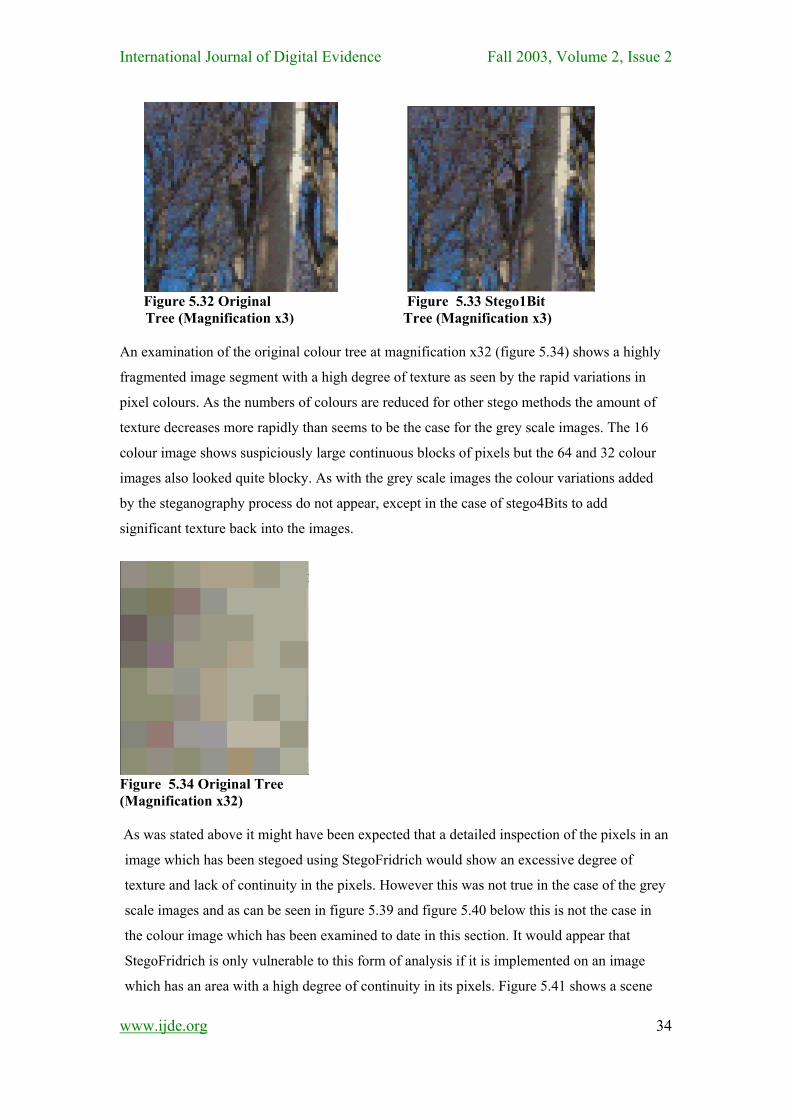
International Journal of Digital Evidence Fall 2003, Volume 2, Issue 2
Figure 5.32 Original Figure 5.33 Stego1Bit
Tree (Magnification x3) Tree (Magnification x3) An examination of the original colour tree at magnification x32 (figure 5.34) shows a highly
fragmented image segment with a high degree of texture as seen by the rapid variations in
pixel colours. As the numbers of colours are reduced for other stego methods the amount of
texture decreases more rapidly than seems to be the case for the grey scale images. The 16
colour image shows suspiciously large continuous blocks of pixels but the 64 and 32 colour
images also looked quite blocky. As with the grey scale images the colour variations added
by the steganography process do not appear, except in the case of stego4Bits to add
significant texture back into the images.
Figure 5.34 Original Tree (Magnification x32) As was stated above it might have been expected that a detailed inspection of the pixels in an
image which has been stegoed using StegoFridrich would show an excessive degree of
texture and lack of continuity in the pixels. However this was not true in the case of the grey
scale images and as can be seen in figure 5.39 and figure 5.40 below this is not the case in
the colour image which has been examined to date in this section. It would appear that
StegoFridrich is only vulnerable to this form of analysis if it is implemented on an image
which has an area with a high degree of continuity in its pixels. Figure 5.41 shows a scene
www.ijde.org
34
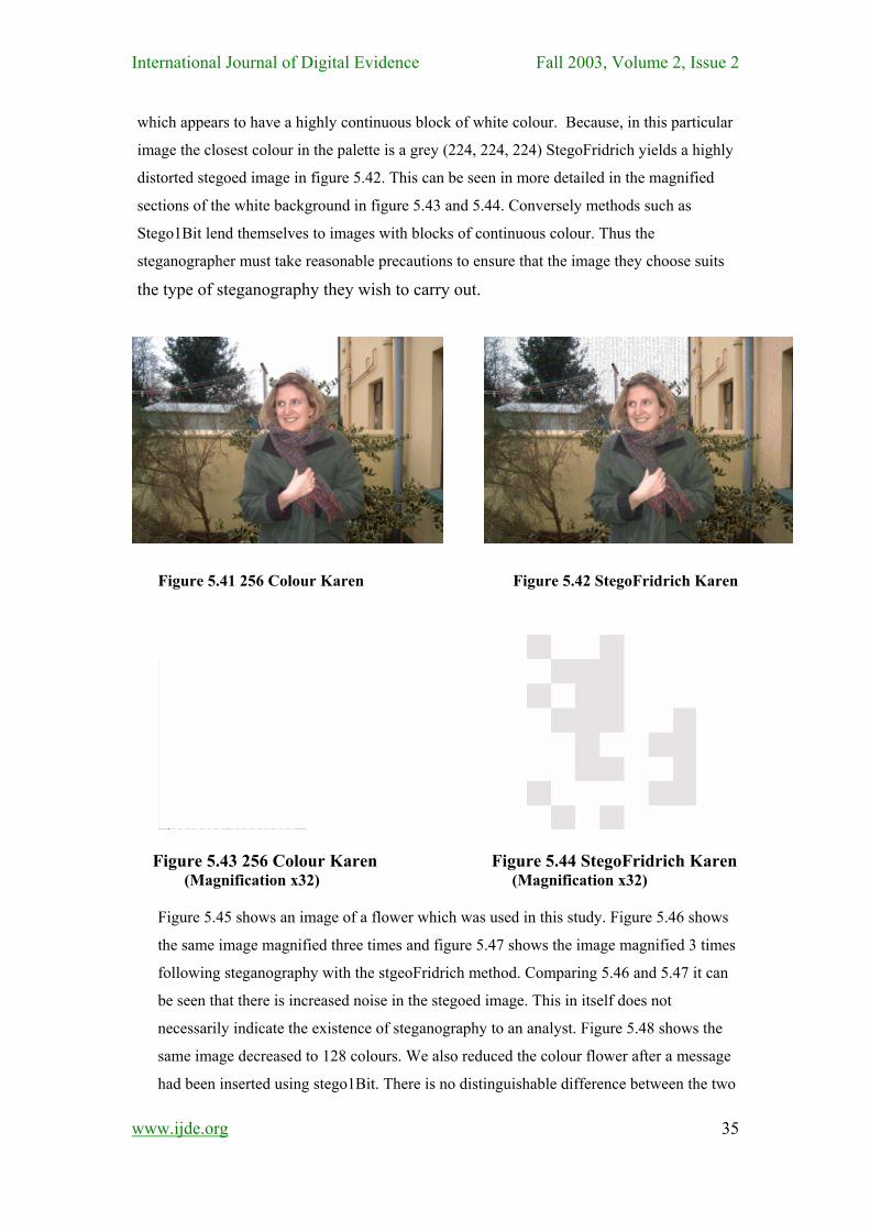
International Journal of Digital Evidence Fall 2003, Volume 2, Issue 2 which appears to have a highly continuous block of white colour. Because, in this particular
image the closest colour in the palette is a grey (224, 224, 224) StegoFridrich yields a highly
distorted stegoed image in figure 5.42. This can be seen in more detailed in the magnified
sections of the white background in figure 5.43 and 5.44. Conversely methods such as
Stego1Bit lend themselves to images with blocks of continuous colour. Thus the
steganographer must take reasonable precautions to ensure that the image they choose suits
the type of steganography they wish to carry out.
Figure 5.41 256 Colour Karen Figure 5.42 StegoFridrich Karen
Figure 5.43 256 Colour Karen Figure 5.44 StegoFridrich Karen (Magnification x32) (Magnification x32)
Figure 5.45 shows an image of a flower which was used in this study. Figure 5.46 shows
the same image magnified three times and figure 5.47 shows the image magnified 3 times
following steganography with the stgeoFridrich method. Comparing 5.46 and 5.47 it can
be seen that there is increased noise in the stegoed image. This in itself does not
necessarily indicate the existence of steganography to an analyst. Figure 5.48 shows the
same image decreased to 128 colours. We also reduced the colour flower after a message
had been inserted using stego1Bit. There is no distinguishable difference between the two
www.ijde.org
35
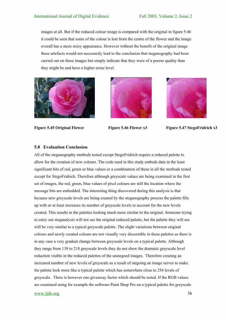
International Journal of Digital Evidence Fall 2003, Volume 2, Issue 2
images at all. But if the reduced colour image is compared with the original in figure 5.46
it could be seen that some of the colour is lost from the centre of the flower and the image
overall has a more noisy appearance. However without the benefit of the original image
these artefacts would not necessarily lead to the conclusion that steganography had been
carried out on these images but simply indicate that they were of a poorer quality than
they might be and have a higher noise level.
Figure 5.45 Original Flower Figure 5.46 Flower x3 Figure 5.47 StegoFridrich x3
5.8 Evaluation Conclusion
All of the steganography methods tested except StegoFridrich require a reduced palette to
allow for the creation of new colours. The code used in this study embeds data in the least
significant bits of red, green or blue values or a combination of these in all the methods tested
except for StegoFridrich. Therefore although greyscale values are being examined in the first
set of images, the red, green, blue values of pixel colours are still the location where the
message bits are embedded. The interesting thing discovered during this analysis is that
because new greyscale levels are being created by the steganography process the palette fills
up with or at least increases its number of greyscale levels to account for the new levels
created. This results in the palettes looking much more similar to the original. Someone trying
to carry out steganalysis will not see the original reduced palette, but the palette they will see
will be very similar to a typical greyscale palette. The slight variations between original
colours and newly created colours are not visually very discernible in these palettes as there is
in any case a very gradual change between greyscale levels on a typical palette. Although
they range from 138 to 218 greyscale levels they do not show the dramatic greyscale level
reduction visible in the reduced palettes of the unstegoed images. Therefore creating an
increased number of new levels of greyscale as a result of stegoing an image serves to make
the palette look more like a typical palette which has somewhere close to 256 levels of
greyscale. There is however one giveaway factor which should be noted. If the RGB values
are examined using for example the software Paint Shop Pro on a typical palette for greyscale
www.ijde.org
36
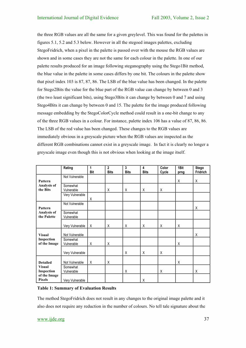
International Journal of Digital Evidence Fall 2003, Volume 2, Issue 2 the three RGB values are all the same for a given greylevel. This was found for the palettes in
figures 5.1, 5.2 and 5.3 below. However in all the stegoed images palettes, excluding
StegoFridrich, when a pixel in the palette is passed over with the mouse the RGB values are
shown and in some cases they are not the same for each colour in the palette. In one of our
palette results produced for an image following steganography using the Stego1Bit method,
the blue value in the palette in some cases differs by one bit. The colours in the palette show
that pixel index 103 is 87, 87, 86. The LSB of the blue value has been changed. In the palette
for Stego2Bits the value for the blue part of the RGB value can change by between 0 and 3
(the two least significant bits), using Stego3Bits it can change by between 0 and 7 and using
Stego4Bits it can change by between 0 and 15. The palette for the image produced following
message embedding by the StegoColorCycle method could result in a one-bit change to any
of the three RGB values in a colour. For instance, palette index 106 has a value of 87, 86, 86.
The LSB of the red value has been changed. These changes to the RGB values are
immediately obvious in a greyscale picture when the RGB values are inspected as the
different RGB combinations cannot exist in a greyscale image. In fact it is clearly no longer a
greyscale image even though this is not obvious when looking at the image itself.
Rating 1
Bit 2 Bits
3 Bits
4 Bits
Color Cycle
1Bit prng
Stego Fridrich
Not Vulnerable
X
X
Somewhat Vulnerable
X
X
X
X
Pattern Analysis of the Bits
Very Vulnerable
X
Not Vulnerable
X
Somewhat Vulnerable
Pattern Analysis of the Palette
Very Vulnerable
X
X
X
X
X
X
Not Vulnerable
X
Somewhat Vulnerable
X
X
X
Visual Inspection of the Image
Very Vulnerable
X
X
X
Not Vulnerable
X
X
X
Somewhat Vulnerable
X
X
X
Detailed Visual Inspection of the Image Pixels
Very Vulnerable
X
Table 1: Summary of Evaluation Results
The method StegoFridrich does not result in any changes to the original image palette and it
also does not require any reduction in the number of colours. No tell tale signature about the
www.ijde.org
37
International Journal of Digital Evidence Fall 2003, Volume 2, Issue 2 fact that steganography has been carried out is therefore given away using this method. A
large and a small message were embedded in the image using Stego1Bit to see what effect
this had on the number of new colours produced and hence the appearance of the palette.
Therefore embedding a larger message actually results in the palette more closely resembling
a typical palette. In conclusion it can be said that a visual inspection of the palette does not
immediately show that steganography has been carried out on the image. In fact the bigger
the message hidden in the image the less obvious it is. However an inspection of the precise
RGB values which make up a range of greyscale levels shows a distinct telltale signature
which is present in all methods which manipulate the pixel values. Only StegoFridrich is not
vulnerable to this type of analysis.
Table 1 shows a summary of the evaluation results presented previously. While some of the
results presented previously can be considered to be a little imprecise due to ambiguity in the
findings, the effect of unexpected but natural artefacts in images, it is reasonable to draw
approximate conclusions with the information available. StegoFridrich while having some
weaknesses particularly where the image being used has not been chosen carefully appears to
be the most secure method by a significant margin. All of the other methods suffer from an
underlying weakness in that the requirement for colour reduction and replacement leaves a
very strong steganography signature in the palette. After StegoFridrich, Stego1BitPRNG and
Stego1Bit are the next most secure methods in that order. The strengths of StegoColorCycle
in terms of having a degree of resistance to pattern analysis of the least significant bits
appears to be cancelled out by degree of colour reduction required. Finally despite the
additional data hiding capacity of Stego2Bits, Stego3Bits and Stego4Bits the security of the
steganography method being used decreases as the data hiding capacity increases making
these progressively less desirable techniques.
6 CONCLUSION As all the of the methods evaluated required either colour reduction of the original images
palette or colour substitution in the stegoed image, they all had their own weaknesses as the
stegoed image inevitably suffered some distortion from the steganography process. In the case
of colour reduction based techniques there were strong tell-tail signs in the palette as well.
Overall the colour rearrangement technique appeared to be the most resistant to detection as
long as suitable images were chosen. Techniques that attempt to maximise the message size
that they can store; appear to be the least resistant to detection.
www.ijde.org
38
International Journal of Digital Evidence Fall 2003, Volume 2, Issue 2 7 REFERENCES
[Brown94]Brown A., S-Tools for Windows, Shareware, 1994.
ftp://idea.sec.dsi.unimi.it/pub/security/crypt/code/s-tools3.zip(version 3)
[Day98] Day Bill and Knudsen Jonathan, Image Processing with Java 2D
www.javaworld.com/javaworld/jw-09-1998/jw-09-media_p.html, August 1998.
[Efford00] Efford, Nick, Digital Image Processing a Practical Introduction using Java,
Addison-Wesley, 2000.
[Fridrich99] Fridrich Jiri, A New Steganographic Method for Palette-Based Images. Center
for Intelligent Systems, SUNY Binghamton, Binghamton, New York. IS&T's PICS
Conference, pp.285-289, 1999.
[Fridrich00] Fridrich Jiri, Rui Du, Secure Steganographic Methods for Palette Images. Center
for Intelligent Systems, Dept. of SS&IE, SUNY Binghamton, Binghamton, New York.
Information Hiding, Third International Workshop, IH'99 Dresden Germany, September /
October Proceedings, Computer Science 1768. pp. 47-60, 2000.
[Hansmann96] Hansmann F. Steganos. Deus Ex Machina Communications.
http://www.steganography.com 1996
[Johnson98] Johnson Neil F., Sushil Jajodia, Steganalysis of Images Created Using Current
Steganography Software, Centre for Secure Information Systems, George Mason University,
Fairfax, Virginia, Information Hiding, Second International Workshop, IH'98 Portland,
Oregon, USA, pp. 273-289, April 1998.
[Johnson01] Johnson Neil F., Zoran Duric, Sushil Jajodia, Information Hiding, and
Watermarking - Attacks & Countermeasures, Kluwer 2001.
[Murray96] Murray James D., William van Ryper, Encyclopedia of Graphics File Formats,
Second Edition, O'Reilly and Associates Inc., 1996
[Pfitzmann96] Pfitzmann Birgit. Information Hiding Terminology. First International
Workshop, Cambridge, UK, Proceedings, Computer Science 1174. pp. 347-350, May -June
www.ijde.org
39
International Journal of Digital Evidence Fall 2003, Volume 2, Issue 2
www.ijde.org
40
1996.
[Wayner02] Wayner Peter, Disappearing Cryptography, Information Hiding: Steganography
and Watermarking, 2nd Edition, Morgan Kaufmann, 2002.
[Westfield99] Westfield Andreas and Andreas Pfitzmann, Attacks on Steganographic
Systems. Third International Workshop, IH'99 Dresden Germany, October Proceedings,
Coputer Science 1768. pp. 61- 76, 1999.
[Zollner98] Zollner J., H. Federrath, H. Klimant, A. Pfitzmann, R. Piotraschke, A. Westfeld,
G. Wicke, G. Wolf, Modelling the Security of Steganographic Systems, Information Hiding,
2nd International Workshop, IH'98 Portland, Oregon, USA, Computer Science 1525. pp.
344-354, April 1998.
© 2003 International Journal of Digital Evidence
ABOUT THE AUTHORS
Kevin Curran is a Lecturer at the University of Ulster in Northern Ireland. Kevin is a member of the Editorial Committee of The Technology Source, IEEE Computer, Journal of Communications and Networks, IEEE Network Journal (USA), IEEE/ACM Transactions on Networking (USA), Computers and Education and the prestigious Journal of Universal Computer Science (J.UCS). His research interests include distributed computing especially emerging trends within wireless ad-hoc networks, distributed objects, dynamic protocol stacks, multimedia transport protocols and mobile systems. He can be contacted at [email protected]. Karen Bailey is a lecturer at the Institute of Technology in Letterkenny, Ireland. She holds a BSc. in Applied Sciences, a master of Philosophy and has just completed a MSc. in Computing and Information Systems. Karen is an active researcher and her research interests include Brewing, Fermentation and Starch Analysis, Steganography, Digital Watermarking, Encryption and Image Processing for Data Security and Data Hiding. Her e-mail is : [email protected].