CHAPTER 12 WORKFLOW ENGINE FOR CLOUDS SURAJ PANDEY, DILEBAN KARUNAMOORTHY, and RAJKUMAR BUYYA 12.1 INTRODUCTION A workflow models a process as consisting of a series of steps that simplifies the complexity of execution and management of applications. Scientific workflows in domains such as high-energy physics and life sciences utilize distributed resources in order to access, manage, and process a large amount of data from a higher level. Processing and managing such large amounts of data require the use of a distributed collection of computation and storage facilities. These resources are often limited in supply and are shared among many competing users. The recent progress in virtualization technologies and the rapid growth of cloud computing services have opened a new paradigm in distributed computing for utilizing existing (and often cheaper) resource pools for on- demand and scalable scientific computing. Scientific Workflow Management Systems (WfMS) need to adapt to this new paradigm in order to leverage the benefits of cloud services. Cloud services vary in the levels of abstraction and hence the type of service they present to application users. Infrastructure virtualization enables provi- ders such as Amazon 1 to offer virtual hardware for use in compute- and data- intensive workflow applications. Platform-as-a-Service (PaaS) clouds expose a higher-level development and runtime environment for building and deploying workflow applications on cloud infrastructures. Such services may also expose domain-specific concepts for rapid-application development. Further up in the cloud stack are Software-as-a-Service providers who offer end users with Cloud Computing: Principles and Paradigms, Edited by Rajkumar Buyya, James Broberg and Andrzej Goscinski Copyright r 2011 John Wiley & Sons, Inc. 1 http://aws.amazon.com 321

Welcome message from author
This document is posted to help you gain knowledge. Please leave a comment to let me know what you think about it! Share it to your friends and learn new things together.
Transcript
CHAPTER 12
WORKFLOW ENGINE FOR CLOUDS
SURAJ PANDEY, DILEBAN KARUNAMOORTHY,and RAJKUMAR BUYYA
12.1 INTRODUCTION
A workflow models a process as consisting of a series of steps that simplifies thecomplexity of execution and management of applications. Scientific workflowsin domains such as high-energy physics and life sciences utilize distributedresources in order to access, manage, and process a large amount of data from ahigher level. Processing and managing such large amounts of data require theuse of a distributed collection of computation and storage facilities. Theseresources are often limited in supply and are shared among many competingusers. The recent progress in virtualization technologies and the rapid growthof cloud computing services have opened a new paradigm in distributedcomputing for utilizing existing (and often cheaper) resource pools for on-demand and scalable scientific computing. Scientific Workflow ManagementSystems (WfMS) need to adapt to this new paradigm in order to leverage thebenefits of cloud services.
Cloud services vary in the levels of abstraction and hence the type of servicethey present to application users. Infrastructure virtualization enables provi-ders such as Amazon1 to offer virtual hardware for use in compute- and data-intensive workflow applications. Platform-as-a-Service (PaaS) clouds expose ahigher-level development and runtime environment for building and deployingworkflow applications on cloud infrastructures. Such services may also exposedomain-specific concepts for rapid-application development. Further up in thecloud stack are Software-as-a-Service providers who offer end users with
Cloud Computing: Principles and Paradigms, Edited by Rajkumar Buyya, James Broberg andAndrzej Goscinski Copyright r 2011 John Wiley & Sons, Inc.
1 http://aws.amazon.com
321
standardized software solutions that could be integrated into existingworkflows.
This chapter presents workflow engines and its integration with the cloudcomputing paradigm. We start by reviewing existing solutions for workflowapplications and their limitations with respect to scalability and on-demandaccess.We thendiscuss someof thekeybenefits that cloud services offerworkflowapplications, compared to traditional grid environments. Next, we give a briefintroduction toworkflowmanagement systems in order to highlight componentsthat will become an essential part of the discussions in this chapter. We discussstrategies for utilizing cloud resources in workflow applications next, along witharchitectural changes, useful tools, and services. We then present a case study onthe use of cloud services for a scientific workflow application and finally end thechapter with a discussion on visionary thoughts and the key challenges to realizethem. In order to aid our discussions, we refer to the workflow managementsystem and cloud middleware developed at CLOUDS Lab, University ofMelbourne. These tools, referred to as Cloudbus toolkit [1], henceforth, aremature platforms arising from years of research and development.
12.2 BACKGROUND
Over the recent past, a considerable body of work has been done on the use ofworkflow systems for scientific applications. Yu and Buyya [2] provide acomprehensive taxonomy of workflow management systems based on work-flow design, workflow scheduling, fault management, and data movement.They characterize and classify different approaches for building and executingworkflows on Grids. They also study existing grid workflow systems high-lighting key features and differences.
Some of the popular workflow systems for scientific applications includeDAGMan (Directed Acyclic Graph MANager) [3, 4], Pegasus [5], Kepler [6],and Taverna workbench [7]. DAGMan is a workflow engine under the Pegasusworkflow management system. Pegasus uses DAGMan to run the executableworkflow. Kepler provides support for Web-service-based workflows. It usesan actor-oriented design approach for composing and executing scientificapplication workflows. The computational components are called actors, andthey are linked together to form a workflow. The Taverna workbench enablesthe automation of experimental methods through the integration of variousservices, including WSDL-based single operation Web services, into workflows.For a detailed description of these systems, we refer you to Yu and Buyya [2].
Scientific workflows are commonly executed on shared infrastructure such asTera-Grid,2 Open Science Grid,3 and dedicated clusters [8]. Existing workflowsystems tend to utilize these global Grid resources that are made available
2 http://www.teragrid.org3 http://www.opensciencegrid.org
322 WORKFLOW ENGINE FOR CLOUDS
through prior agreements and typically at no cost. The notion of leveragingvirtualized resources was new, and the idea of using resources as a utility [9, 10]was limited to academic papers and was not implemented in practice. With theadvent of cloud computing paradigm, economy-based utility computing isgaining widespread adoption in the industry.
Deelman et al. [11] presented a simulation-based study on the costs involvedwhen executing scientific application workflows using cloud services. Theystudied the cost performance trade-offs of different execution and resourceprovisioning plans, and they also studied the storage and communication feesof Amazon S3 in the context of an astronomy application known as Montage[5, 10]. They conclude that cloud computing is a cost-effective solution for data-intensive applications.
The Cloudbus toolkit [1] is our initiative toward providing viable solutionsfor using cloud infrastructures. We propose a wider vision that incorporates aninter-cloud architecture and a market-oriented utility computing model. TheCloudbus workflow engine [12], presented in the sections to follow, is a steptoward scaling workflow applications on clouds using market-orientedcomputing.
12.3 WORKFLOW MANAGEMENT SYSTEMS AND CLOUDS
The primary benefit of moving to clouds is application scalability. Unlike grids,scalability of cloud resources allows real-time provisioning of resources to meetapplication requirements at runtime or prior to execution. The elastic nature ofclouds facilitates changing of resource quantities and characteristics to vary atruntime, thus dynamically scaling up when there is a greater need for additionalresources and scaling down when the demand is low. This enables workflowmanagement systems to readily meet quality-of-service (QoS) requirements ofapplications, as opposed to the traditional approach that required advancereservation of resources in global multi-user grid environments. With mostcloud computing services coming from large commercial organizations, service-level agreements (SLAs) have been an important concern to both the serviceproviders and consumers. Due to competitions within emerging serviceproviders, greater care is being taken in designing SLAs that seek to offer (a)better QoS guarantees to customers and (b) clear terms for compensation in theevent of violation. This allows workflow management systems to provide betterend-to-end guarantees when meeting the service requirements of users bymapping them to service providers based on characteristics of SLAs. Econom-ically motivated, commercial cloud providers strive to provide better servicesguarantees compared to grid service providers. Cloud providers also takeadvantage of economies of scale, providing compute, storage, and bandwidthresources at substantially lower costs. Thus utilizing public cloud services couldbe economical and a cheaper alternative (or add-on) to the more expensivededicated resources. One of the benefits of using virtualized resources for
12.3 WORKFLOW MANAGEMENT SYSTEMS AND CLOUDS 323
workflow execution, as opposed to having direct access to the physicalmachine, is the reduced need for securing the physical resource from maliciouscode using techniques such as sandboxing. However, the long-term effect ofusing virtualized resources in clouds that effectively share a “slice” of thephysical machine, as opposed to using dedicated resources for high-perfor-mance applications, is an interesting research question.
12.3.1 Architectural Overview
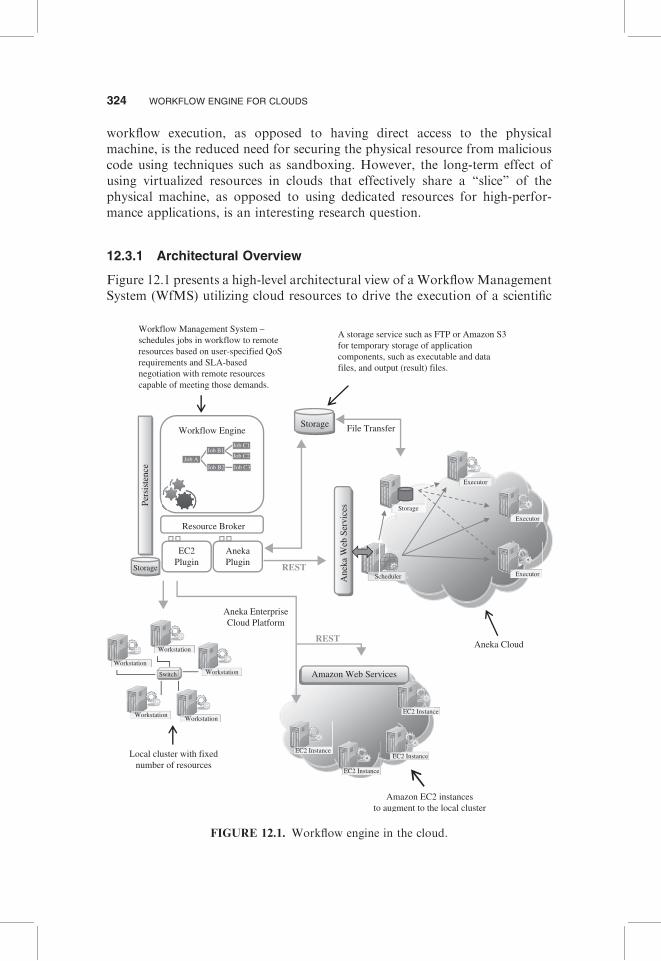
Figure 12.1 presents a high-level architectural view of a WorkflowManagementSystem (WfMS) utilizing cloud resources to drive the execution of a scientific
Switch
Aneka Cloud
Workflow Engine
Resource Broker
Pers
iste
nce
Storage
EC2Plugin
AnekaPlugin
A storage service such as FTP or Amazon S3for temporary storage of applicationcomponents, such as executable and datafiles, and output (result) files.
Workflow Management System –schedules jobs in workflow to remoteresources based on user-specified QoSrequirements and SLA-basednegotiation with remote resourcescapable of meeting those demands.
Local cluster with fixednumber of resources
Amazon EC2 instancesto augment to the local cluster
Storage
Executor
Executor
Executor
Storage
Scheduler
EC2 Instance
EC2 Instance
EC2 Instance
EC2 Instance
Workstation
Workstation
Workstation
Workstation Workstation
Ane
ka W
eb S
ervi
ces
File Transfer
REST
Aneka EnterpriseCloud Platform
REST
Job C1
Job C2
Job C3Job B2
Job B1
Job A
Amazon Web Services
FIGURE 12.1. Workflow engine in the cloud.
324 WORKFLOW ENGINE FOR CLOUDS
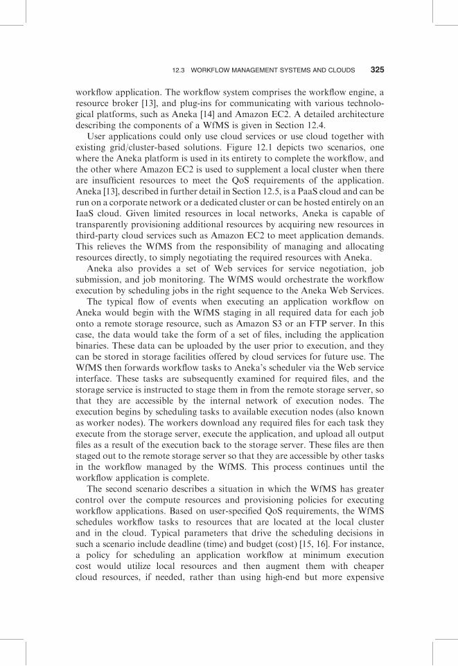
workflow application. The workflow system comprises the workflow engine, aresource broker [13], and plug-ins for communicating with various technolo-gical platforms, such as Aneka [14] and Amazon EC2. A detailed architecturedescribing the components of a WfMS is given in Section 12.4.
User applications could only use cloud services or use cloud together withexisting grid/cluster-based solutions. Figure 12.1 depicts two scenarios, onewhere the Aneka platform is used in its entirety to complete the workflow, andthe other where Amazon EC2 is used to supplement a local cluster when thereare insufficient resources to meet the QoS requirements of the application.Aneka [13], described in further detail in Section 12.5, is a PaaS cloud and can berun on a corporate network or a dedicated cluster or can be hosted entirely on anIaaS cloud. Given limited resources in local networks, Aneka is capable oftransparently provisioning additional resources by acquiring new resources inthird-party cloud services such as Amazon EC2 to meet application demands.This relieves the WfMS from the responsibility of managing and allocatingresources directly, to simply negotiating the required resources with Aneka.
Aneka also provides a set of Web services for service negotiation, jobsubmission, and job monitoring. The WfMS would orchestrate the workflowexecution by scheduling jobs in the right sequence to the Aneka Web Services.
The typical flow of events when executing an application workflow onAneka would begin with the WfMS staging in all required data for each jobonto a remote storage resource, such as Amazon S3 or an FTP server. In thiscase, the data would take the form of a set of files, including the applicationbinaries. These data can be uploaded by the user prior to execution, and theycan be stored in storage facilities offered by cloud services for future use. TheWfMS then forwards workflow tasks to Aneka’s scheduler via the Web serviceinterface. These tasks are subsequently examined for required files, and thestorage service is instructed to stage them in from the remote storage server, sothat they are accessible by the internal network of execution nodes. Theexecution begins by scheduling tasks to available execution nodes (also knownas worker nodes). The workers download any required files for each task theyexecute from the storage server, execute the application, and upload all outputfiles as a result of the execution back to the storage server. These files are thenstaged out to the remote storage server so that they are accessible by other tasksin the workflow managed by the WfMS. This process continues until theworkflow application is complete.
The second scenario describes a situation in which the WfMS has greatercontrol over the compute resources and provisioning policies for executingworkflow applications. Based on user-specified QoS requirements, the WfMSschedules workflow tasks to resources that are located at the local clusterand in the cloud. Typical parameters that drive the scheduling decisions insuch a scenario include deadline (time) and budget (cost) [15, 16]. For instance,a policy for scheduling an application workflow at minimum executioncost would utilize local resources and then augment them with cheapercloud resources, if needed, rather than using high-end but more expensive
12.3 WORKFLOW MANAGEMENT SYSTEMS AND CLOUDS 325
cloud resources. On the contrary, a policy that scheduled workflows to achieveminimum execution time would always use high-end cluster and cloudresources, irrespective of costs. The resource provisioning policy determinesthe extent of additional resources to be provisioned on the public clouds. In thissecond scenario, the WfMS interacts directly with the resources provisioned.When using Aneka, however, all interaction takes place via the Web serviceinterface.
The following sections focuses on the integration of workflow managementsystems and clouds and describes in detail practical issues involved in usingclouds for scientific workflow applications.
12.4 ARCHITECTURE OF WORKFLOW MANAGEMENT SYSTEMS
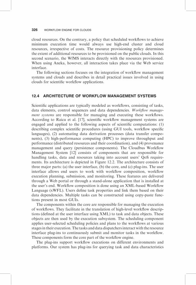
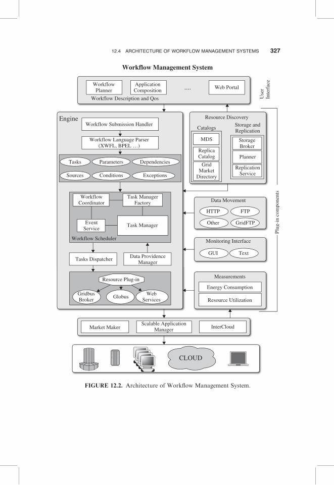
Scientific applications are typically modeled as workflows, consisting of tasks,data elements, control sequences and data dependencies. Workflow manage-ment systems are responsible for managing and executing these workflows.According to Raicu et al. [17], scientific workflow management systems areengaged and applied to the following aspects of scientific computations: (1)describing complex scientific procedures (using GUI tools, workflow specificlanguages), (2) automating data derivation processes (data transfer compo-nents), (3) high-performance computing (HPC) to improve throughput andperformance (distributed resources and their coordination), and (4) provenancemanagement and query (persistence components). The Cloudbus WorkflowManagement System [12] consists of components that are responsible forhandling tasks, data and resources taking into account users’ QoS require-ments. Its architecture is depicted in Figure 12.2. The architecture consists ofthree major parts: (a) the user interface, (b) the core, and (c) plug-ins. The userinterface allows end users to work with workflow composition, workflowexecution planning, submission, and monitoring. These features are deliveredthrough a Web portal or through a stand-alone application that is installed atthe user’s end. Workflow composition is done using an XML-based WorkflowLanguage (xWFL). Users define task properties and link them based on theirdata dependencies. Multiple tasks can be constructed using copy-paste func-tions present in most GUIs.
The components within the core are responsible for managing the executionof workflows. They facilitate in the translation of high-level workflow descrip-tions (defined at the user interface using XML) to task and data objects. Theseobjects are then used by the execution subsystem. The scheduling componentapplies user-selected scheduling policies and plans to the workflows at variousstages in their execution.The tasks anddatadispatchers interactwith the resourceinterface plug-ins to continuously submit and monitor tasks in the workflow.These components form the core part of the workflow engine.
The plug-ins support workflow executions on different environments andplatforms. Our system has plug-ins for querying task and data characteristics
326 WORKFLOW ENGINE FOR CLOUDS
Workflow Management System
ApplicationComposition
WorkflowPlanner
Workflow Description and Qos
Workflow Submission HandlerResource Discovery
Data Movement
Monitoring Interface
Measurements
InterCloudScalable Application
Manager
CLOUD
Market Maker
Energy Consumption
Resource Utilization
Catalogs
MDS StorageBroker
HTTP
GUI Text
Other
FTP
GridFTP
Planner
ReplicationService
ReplicaCatalog
GridMarket
Directory
Storage andReplication
Workflow Language Parser(XWFL, BPEL …)
Tasks
Sources
Parameters
Conditions
WorkflowCoordinator
EventService
Task Manager
Data ProvidenceManager
Tasks Dispatcher
Resource Plug-in
GlobusGridbusBroker
WebServices
Workflow Scheduler
Task ManagerFactory
Dependencies
Exceptions
Engine
Web Portal....
Use
rIn
terf
ace
Plug
-in
com
pone
nts
FIGURE 12.2. Architecture of Workflow Management System.
12.4 ARCHITECTURE OF WORKFLOW MANAGEMENT SYSTEMS 327
(e.g., querying metadata services, reading from trace files), transferring data toand from resources (e.g., transfer protocol implementations, and storage andreplication services), monitoring the execution status of tasks and applications(e.g., real-time monitoring GUIs, logs of execution, and the scheduled retrievalof task status), and measuring energy consumption.
The resources are at the bottom layer of the architecture and includeclusters, global grids, and clouds. The WfMS has plug-in components forinteracting with various resource management systems present at the front endof distributed resources. Currently, the Cloudbus WfMS supports Aneka, Pbs,Globus, and fork-based middleware. The resource managers may communicatewith the market maker, scalable application manager, and InterCloud servicesfor global resource management [18].
12.5 UTILIZING CLOUDS FOR WORKFLOW EXECUTION
Taking the leap to utilizing cloud services for scientific workflow applicationsrequires an understanding of the types of clouds services available, the requiredcomponent changes in workflow systems for interacting with cloud services, theset of tools available to support development and deployment efforts, the stepsinvolved in deploying workflow systems and services on the cloud, and anappreciation of the key benefits and challenges involved. In the sections tofollow, we take a closer look at some of these issues. We begin by introducingthe reader to the Aneka Enterprise Cloud service. We do this for two reasons.First, Aneka serves as a useful tool for utilizing clouds, including platformabstraction and dynamic provisioning. Second, we describe later in the chaptera case study detailing the use of Aneka to execute a scientific workflowapplication on clouds.
12.5.1 Aneka
Aneka is a distributed middleware for deploying platform-as-a-service (PaaS)offerings (Figure 12.3). Developed at CLOUDS Lab, University of Melbourne,Aneka is the result of years of research on cluster, grid, and cloud computingfor high-performance computing (HPC) applications. Aneka, which is both adevelopment and runtime environment, is available for public use (for a cost),4
can be installed on corporate networks, or dedicated clusters, or can be hostedon infrastructure clouds like Amazon EC2. In comparison, similar PaaSservices such as Google AppEngine [19] and Windows Azure [20] are in-houseplatforms hosted on infrastructures owned by the respective companies. Anekawas developed on Microsoft’s.NET Framework 2.0 and is compatible withother implementations of the ECMA 335 standard [21], such as Mono. Aneka
4 http://www.manjrasoft.com
328 WORKFLOW ENGINE FOR CLOUDS
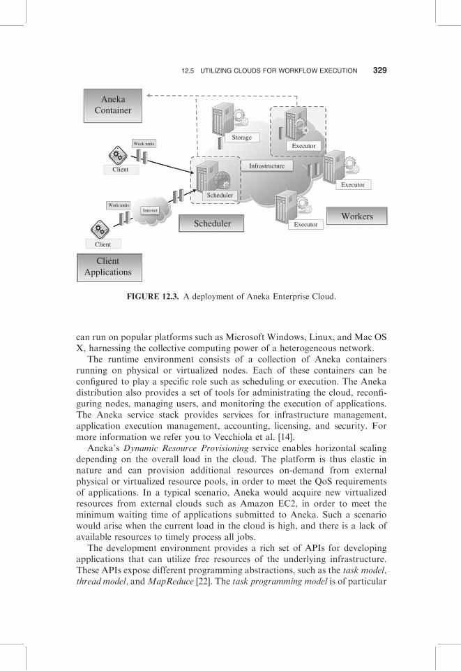
can run on popular platforms such as Microsoft Windows, Linux, and Mac OSX, harnessing the collective computing power of a heterogeneous network.
The runtime environment consists of a collection of Aneka containersrunning on physical or virtualized nodes. Each of these containers can beconfigured to play a specific role such as scheduling or execution. The Anekadistribution also provides a set of tools for administrating the cloud, reconfi-guring nodes, managing users, and monitoring the execution of applications.The Aneka service stack provides services for infrastructure management,application execution management, accounting, licensing, and security. Formore information we refer you to Vecchiola et al. [14].
Aneka’s Dynamic Resource Provisioning service enables horizontal scalingdepending on the overall load in the cloud. The platform is thus elastic innature and can provision additional resources on-demand from externalphysical or virtualized resource pools, in order to meet the QoS requirementsof applications. In a typical scenario, Aneka would acquire new virtualizedresources from external clouds such as Amazon EC2, in order to meet theminimum waiting time of applications submitted to Aneka. Such a scenariowould arise when the current load in the cloud is high, and there is a lack ofavailable resources to timely process all jobs.
The development environment provides a rich set of APIs for developingapplications that can utilize free resources of the underlying infrastructure.These APIs expose different programming abstractions, such as the task model,thread model, andMapReduce [22]. The task programming model is of particular
AnekaContainer
Work units
Internet
Client
Client
Storage
Infrastructure
Executor
Executor
Executor
Scheduler
Work units
ClientApplications
SchedulerWorkers
FIGURE 12.3. A deployment of Aneka Enterprise Cloud.
12.5 UTILIZING CLOUDS FOR WORKFLOW EXECUTION 329
importance to the current discussion. It models “independent bag of tasks”(BoT) applications that are composed of a collection of work units independentof each other, and it may be executed in any given order. One of the benefits ofthe task programming model is its simplicity, making it easy to run legacyapplications on the cloud. An application using the task model composes one ormore task instances and forwards them as work units to the scheduler. Thescheduling service currently supports the First-In-First-Out, First-In-First-Outwith Backfilling, Clock-Rate Priority, and Preemption-Based Priority Queuescheduling algorithms. The runtime environment also provides two specializedservices to support this model: the task scheduling service and the task executionservice.
The storage service provides a temporary repository for application files—that is, input files that are required for task execution, and output files that arehe result of execution. Prior to dispatching work units, any files requiredare staged-in to the storage service from the remote location. This remotelocation can be either the client machine, a remote FTP server, or a cloudstorage service such as Amazon S3. The work units are then dispatched toexecutors, which download the files before execution. Any output filesproduced as a result of the execution are uploaded back to the storage service.From here they are staged-out to the remote storage location.
12.5.2 Aneka Web Services
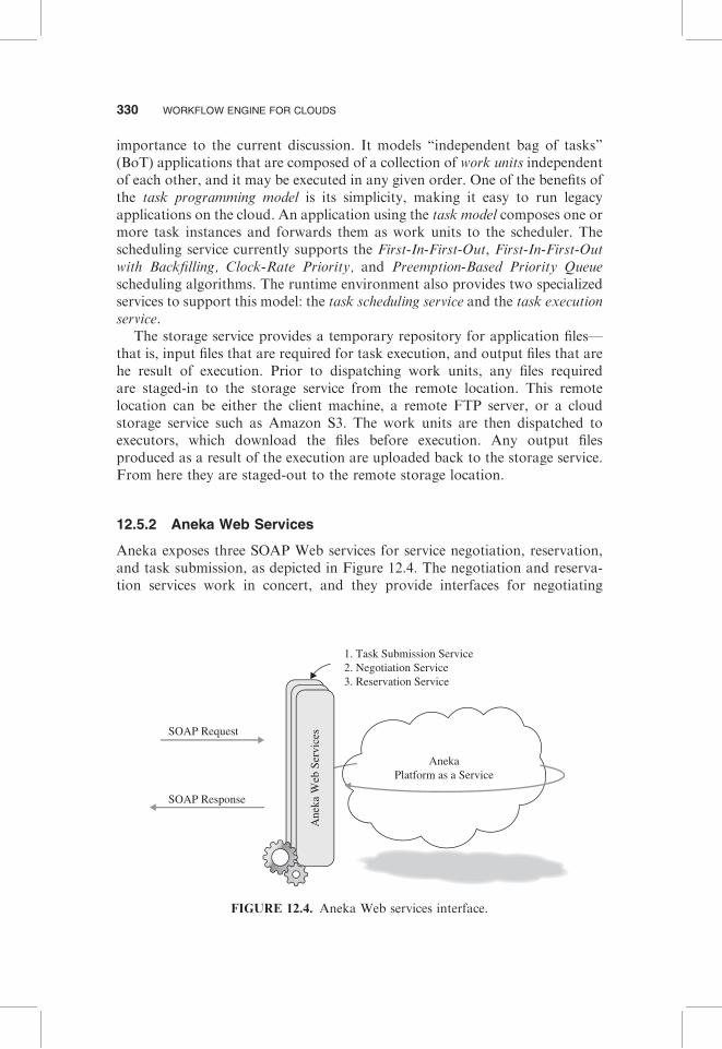
Aneka exposes three SOAP Web services for service negotiation, reservation,and task submission, as depicted in Figure 12.4. The negotiation and reserva-tion services work in concert, and they provide interfaces for negotiating
1. Task Submission Service2. Negotiation Service3. Reservation Service
SOAP Request
AnekaPlatform as a Service
SOAP Response
Ane
ka W
eb S
ervi
ces
FIGURE 12.4. Aneka Web services interface.
330 WORKFLOW ENGINE FOR CLOUDS
resource use and reserving them in Aneka for predetermined timeslots. As such,these services are only useful when Aneka has limited resources to work withand no opportunities for provisioning additional resources. The task Webservice provides a SOAP interface for executing jobs on Aneka. Based on thetask programming model, this service allows remote clients to submit jobs,monitor their status, and abort jobs.
12.5.3 General Approach
Traditional WfMSs were designed with a centralized architecture and were thustied to a single machine. Moving workflow engines to clouds requires (a)architectural changes and (b) integration of cloud management tools.
Architectural Changes. Most components of a WfMS can be separated fromthe core engine so that they can be executed on different cloud services. Eachseparated component could communicate with a centralized or replicatedworkflow engine using events. The manager is responsible for coordinatingthe distribution of load to its subcomponents, such as the Web server,persistence, monitoring units, and so forth.
In our WfMS, we have separated the components that form the architectureinto the following: user interface, core, and plug-ins. The user interface can nowbe coupled with a Web server running on a “large” instance of cloud that canhandle increasing number of users. The Web request from users accessing theWfMS via a portal is thus offloaded to a different set of resources.
Similarly, the core and plug-in components can be hosted on different typesof instances separately. Depending on the size of the workload from users, thesecomponents could be migrated or replicated to other resources, or reinforcedwith additional resources to satisfy the increased load. Thus, employingdistributed modules of the WfMS on the basis of application requirementshelps scale the architecture.
Integration of Cloud Management Tools. As the WfMS is broken downinto components to be hosted across multiple cloud resources, we need amechanism to (a) access, transfer, and store data and (b) enable and monitorexecutions that can utilize this approach of scalable distribution ofcomponents.
The cloud service provider may provide APIs and tools for discovering theVM instances that are associated to a user’s account. Because various types ofinstances can be dynamically created, their characteristics such as CPUcapacity and amount of available memory are a part of the cloud serviceprovider’s specifications. Similarly, for data storage and access, a cloud mayprovide data sharing, data movement, and access rights management capabil-ities to user’s applications. Cloud measurement tools may be in place toaccount for the amount of data and computing power used, so that users arecharged on the pay-per-use basis. A WfMS now needs to access these tools
12.5 UTILIZING CLOUDS FOR WORKFLOW EXECUTION 331
to discover and characterize the resources available in the cloud. It also needs tointerpret the access rights (e.g., access control lists provided by Amazon),use the data movement APIs, and share mechanisms between VMs to fullyutilize the benefits of moving to clouds. In other words, traditional catalogservices such as the Globus Monitoring and Discovery Service (MDS) [23],Replica Location Services, Storage Resource Brokers, Network WeatherService [24], and so on could be easily replaced by more user-friendly andscalable tools and APIs associated with a cloud service provider. We describesome of these tools in the following section.
12.5.4 Tools for Utilizing Clouds in WfMS
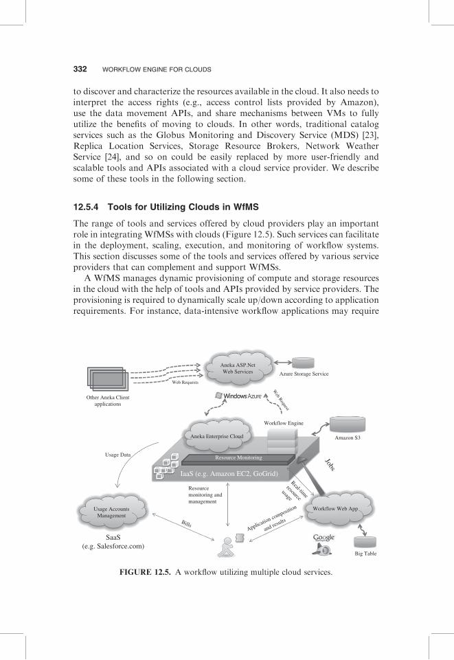
The range of tools and services offered by cloud providers play an importantrole in integrating WfMSs with clouds (Figure 12.5). Such services can facilitatein the deployment, scaling, execution, and monitoring of workflow systems.This section discusses some of the tools and services offered by various serviceproviders that can complement and support WfMSs.
A WfMS manages dynamic provisioning of compute and storage resourcesin the cloud with the help of tools and APIs provided by service providers. Theprovisioning is required to dynamically scale up/down according to applicationrequirements. For instance, data-intensive workflow applications may require
Aneka ASP.NetWeb Services Azure Storage Service
Web Requests
Amazon S3
Big Table
Web Request
Aneka Enterprise Cloud
Other Aneka Clientapplications
Resource MonitoringUsage Data
IaaS (e.g. Amazon EC2, GoGrid)
Jobs
Resourcemonitoring andmanagement
Application composition
and results
Real-time
resourceusage
Bills
SaaS(e.g. Salesforce.com)
Usage AccountsManagement
Workflow Web App
Workflow Engine
FIGURE 12.5. A workflow utilizing multiple cloud services.
332 WORKFLOW ENGINE FOR CLOUDS
large amount of disk space for storage. A WfMS could provision dynamicvolumes of large capacity that could be shared across all instances of VMs(similar to snapshots and volumes provided by Amazon). Similarly, forcompute-intensive tasks in an workflow, a WfMS could provision specificinstances that would help accelerate the execution of these compute-intensivetasks.
A WfMS implements scheduling policies to assign tasks to resources basedon applications’ objectives. This task-resource mapping is dependent on severalfactors: compute resource capacity, application requirements, user’s QoS, andso forth. Based on these objectives, a WfMS could also direct a VMprovisioning system to consolidate data center loads by migrating VMs sothat it could make scheduling decisions based on locality of data and computeresources.
A persistence mechanism is often important in workflow managementsystems and for managing metadata such as available resources, job queues,job status, and user data including large input and output files. Technologiessuch as Amazon S3, Google’s BigTable, and the Windows Azure StorageServices can support most storage requirements for workflow systems, whilealso being scalable, reliable, and secure. If large quantities of user data arebeing dealt with, such as a large number of brain images used in functionalmagnetic resonance imaging (fMRI) studies [12], transferring them online canbe both expensive and time-consuming. In such cases, traditional post canprove to be cheaper and faster. Amazon’s AWS Import/Export5 is one suchservice that aims to speed up data movement by transferring large amounts ofdata in portable storage devices. The data are shipped to/from Amazon andoffloaded into/from S3 buckets using Amazon’s high-speed internal network.The cost savings can be significant when transferring data on the order ofterabytes.
Most cloud providers also offer services and APIs for tracking resourceusage and the costs incurred. This can complement workflow systems thatsupport budget-based scheduling by utilizing real-time data on the resourcesused, the duration, and the expenditure. This information can be used both formaking scheduling decisions on subsequent jobs and for billing the user at thecompletion of the workflow application.6
Cloud services such as Google App Engine and Windows Azure provideplatforms for building scalable interactive Web applications. This makes itrelatively easy to port the graphical components of a workflow managementsystem to such platforms while benefiting from their inherent scalability andreduced administration. For instance, such components deployed on GoogleApp Engine can utilize the same scalable systems that drive Google applica-tions, including technologies such as BigTable [25] and GFS [26].
5 http://aws.amazon.com/importexport/6 http://aws.amazon.com/devpay/
12.5 UTILIZING CLOUDS FOR WORKFLOW EXECUTION 333
12.6 CASE STUDY: EVOLUTIONARY MULTIOBJECTIVEOPTIMIZATIONS
This section presents a scientific application workflow based on an iterativetechnique for optimizing multiple search objectives, known as evolutionarymultiobjective optimization (EMO) [27]. EMO is a technique based on geneticalgorithms. Genetic algorithms are search algorithms used for finding optimalsolutions in a large space where deterministic or functional approaches are notviable. Genetic algorithms use heuristics to find an optimal solution that isacceptable within a reasonable amount of time. In the presence of manyvariables and complex heuristic functions, the time consumed in finding even anacceptable solution can be too large. However, when multiple instances are runin parallel in a distributed setting using different variables, the required time forcomputation can be drastically reduced.
12.6.1 Objectives
The following are the objectives for modeling and executing an EMO workflowon clouds:
� Design an execution model for EMO, expressed in the form of a workflow,such that multiple distributed resources can be utilized.
� Parallelize the execution of EMO tasks for reducing the total completiontime.
� Dynamically provision compute resources needed for timely completionof the application when the number of tasks increase.
� Repeatedly carry out similar experiments as and when required.
� Manage application execution, handle faults, and store the final results foranalysis.
12.6.2 Workflow Solution
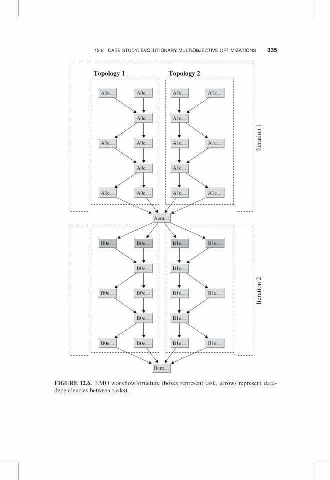
In order to parallelize the execution of EMO, we construct a workflow modelfor systematically executing the tasks. A typical workflow structure is depictedin Figure 12.6.
In our case study, the EMO application consists of five different topologies,upon which the iteration is done. These topologies are defined in five differentbinary files. Each file becomes the input files for the top level tasks (A0emo1,A0emo, . . . ). We create a separate branch for each topology file. In Figure 12.6,there are two branches, which get merged on level 6. The tasks at the root leveloperate on the topologies to create new population, which is then mergedby the task named “emomerge.” In Figure 12.6, we see two “emomerge” tasksin the 2nd level, one task in the 6th level that merges two branches and thensplits the population to two branches again, two tasks on the 8th and 10th
334 WORKFLOW ENGINE FOR CLOUDS
A0e…
Topology 1 Topology 2
Iter
atio
n 1
Iter
atio
n 2
A0e…
A0e…
A0e…
A0e…
A0e…
A1e…
A1e…
A1e…
Aem…
Bem…
A1e…
A1e…
A1e…
A1e… A1e…
B0e… B0e… B1e…
B0e… B1e…
B0e… B1e…
B0e… B1e…
B1e…
B0e… B1e…
B0e… B1e…B0e… B1e…
A0e…
A0e…
FIGURE 12.6. EMO workflow structure (boxes represent task, arrows represent data-
dependencies between tasks).
12.6 CASE STUDY: EVOLUTIONARY MULTIOBJECTIVE OPTIMIZATIONS 335
levels, and the final task on the 12th level. In the example figure, each topologyis iterated two times in a branch before getting merged. The merged populationis then split. This split is done two times in the figure. The tasks labeled B0e andB1e (depicted as darker shade in Figure 12.6) is the start of second iteration.
12.6.3 Deployment and Results
EMO Application. We use ZDT2 [27] as a test function for the objectivefunction. The workflow for this problem is depicted in Figure 12.6.
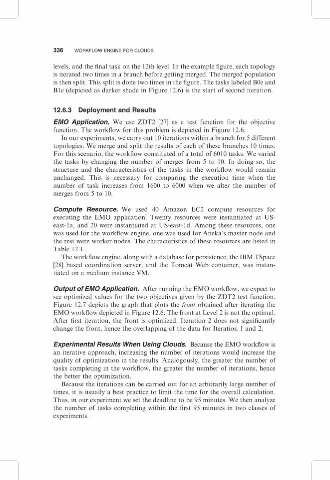
In our experiments, we carry out 10 iterations within a branch for 5 differenttopologies. We merge and split the results of each of these branches 10 times.For this scenario, the workflow constituted of a total of 6010 tasks. We variedthe tasks by changing the number of merges from 5 to 10. In doing so, thestructure and the characteristics of the tasks in the workflow would remainunchanged. This is necessary for comparing the execution time when thenumber of task increases from 1600 to 6000 when we alter the number ofmerges from 5 to 10.
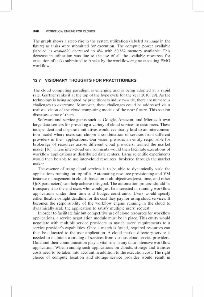
Compute Resource. We used 40 Amazon EC2 compute resources forexecuting the EMO application. Twenty resources were instantiated at US-east-1a, and 20 were instantiated at US-east-1d. Among these resources, onewas used for the workflow engine, one was used for Aneka’s master node andthe rest were worker nodes. The characteristics of these resources are listed inTable 12.1.
The workflow engine, along with a database for persistence, the IBM TSpace[28] based coordination server, and the Tomcat Web container, was instan-tiated on a medium instance VM.
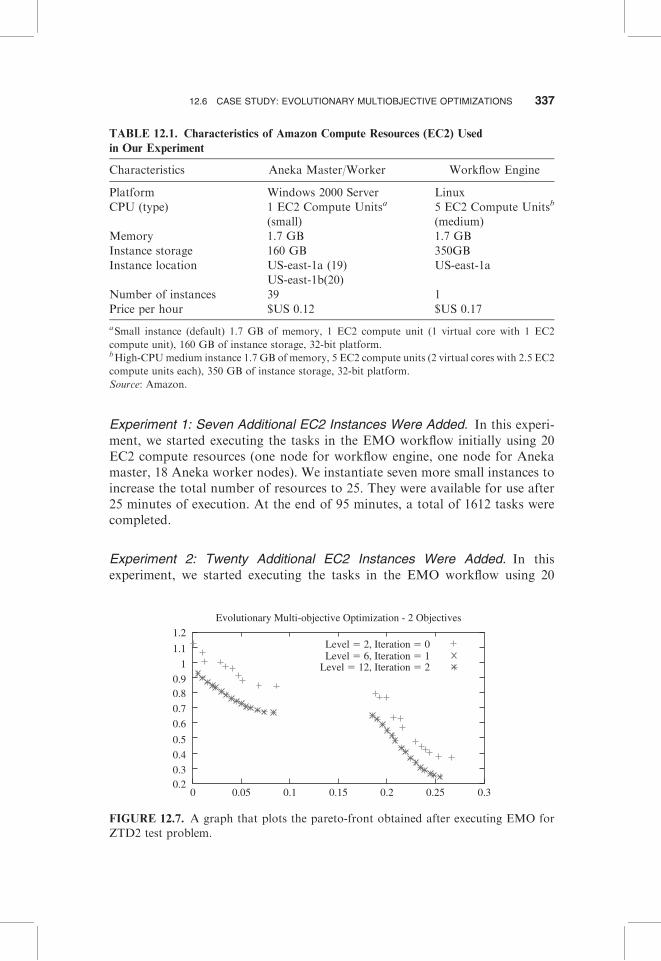
Output of EMO Application. After running the EMO workflow, we expect tosee optimized values for the two objectives given by the ZDT2 test function.Figure 12.7 depicts the graph that plots the front obtained after iterating theEMO workflow depicted in Figure 12.6. The front at Level 2 is not the optimal.After first iteration, the front is optimized. Iteration 2 does not significantlychange the front, hence the overlapping of the data for Iteration 1 and 2.
Experimental Results When Using Clouds. Because the EMO workflow isan iterative approach, increasing the number of iterations would increase thequality of optimization in the results. Analogously, the greater the number oftasks completing in the workflow, the greater the number of iterations, hencethe better the optimization.
Because the iterations can be carried out for an arbitrarily large number oftimes, it is usually a best practice to limit the time for the overall calculation.Thus, in our experiment we set the deadline to be 95 minutes. We then analyzethe number of tasks completing within the first 95 minutes in two classes ofexperiments.
336 WORKFLOW ENGINE FOR CLOUDS
Experiment 1: Seven Additional EC2 Instances Were Added. In this experi-ment, we started executing the tasks in the EMO workflow initially using 20EC2 compute resources (one node for workflow engine, one node for Anekamaster, 18 Aneka worker nodes). We instantiate seven more small instances toincrease the total number of resources to 25. They were available for use after25 minutes of execution. At the end of 95 minutes, a total of 1612 tasks werecompleted.
Experiment 2: Twenty Additional EC2 Instances Were Added. In thisexperiment, we started executing the tasks in the EMO workflow using 20
TABLE 12.1. Characteristics of Amazon Compute Resources (EC2) Used
in Our Experiment
Characteristics Aneka Master/Worker Workflow Engine
Platform Windows 2000 Server Linux
CPU (type) 1 EC2 Compute Unitsa
(small)
5 EC2 Compute Unitsb
(medium)
Memory 1.7 GB 1.7 GB
Instance storage 160 GB 350GB
Instance location US-east-1a (19)
US-east-1b(20)
US-east-1a
Number of instances 39 1
Price per hour $US 0.12 $US 0.17
aSmall instance (default) 1.7 GB of memory, 1 EC2 compute unit (1 virtual core with 1 EC2
compute unit), 160 GB of instance storage, 32-bit platform.bHigh-CPUmedium instance 1.7 GB of memory, 5 EC2 compute units (2 virtual cores with 2.5 EC2
compute units each), 350 GB of instance storage, 32-bit platform.
Source: Amazon.
Evolutionary Multi-objective Optimization - 2 Objectives
Level � 2, Iteration � 0Level � 6, Iteration � 1
Level � 12, Iteration � 2
1.2
1.1
1
0.90.8
0.7
0.6
0.5
0.4
0.30.2
0 0.05 0.1 0.15 0.2 0.25 0.3
FIGURE 12.7. A graph that plots the pareto-front obtained after executing EMO for
ZTD2 test problem.
12.6 CASE STUDY: EVOLUTIONARY MULTIOBJECTIVE OPTIMIZATIONS 337
EC2 compute resources, similar to Experiment 1. We instantiated 20 more EC2instances after noticing the linear increase in task completion rate. Theseinstances however were available for use after 40 minutes of execution. At theend of 95 minutes, a total of 3221 tasks were completed.
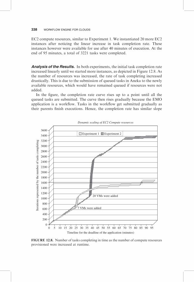
Analysis of the Results. In both experiments, the initial task completion rateincreased linearly until we started more instances, as depicted in Figure 12.8. Asthe number of resources was increased, the rate of task completing increaseddrastically. This is due to the submission of queued tasks in Aneka to the newlyavailable resources, which would have remained queued if resources were notadded.
In the figure, the completion rate curve rises up to a point until all thequeued tasks are submitted. The curve then rises gradually because the EMOapplication is a workflow. Tasks in the workflow get submitted gradually astheir parents finish executions. Hence, the completion rate has similar slope
3600
3400
3200
3000
2800
2600
2400
2200
2000
1800
1600
1400
1200
1000
800
600
400
200
00 5 10 15 20 25 30 35 40 45 50
Timeline for the deadline of the application (minutes)
Dynamic scaling of EC2 Compute resources
7 VMs were added
20 VMs were added
Iter
atio
ns r
epre
sent
ed b
y th
e nu
mbe
r of
task
s co
mpl
etin
g
55 60 65 70 75 80 85 90 95
Experiment 1 Experiment 2
FIGURE 12.8. Number of tasks completing in time as the number of compute resources
provisioned were increased at runtime.
338 WORKFLOW ENGINE FOR CLOUDS
as the initial rate, even after increasing the number of resources (30 to 45minutes for Experiment 1; 45 to 70 minutes for Experiment 2). When moretasks began completing as a result of adding new resources, the workflowengine was able to submit additional tasks for execution. As a result, tasksstarted competing for resources and hence were being queued by Aneka.Because of this queuing at Aneka’s scheduler, the curve flattens after 45minutes for Experiment 1 and after 70 minutes for Experiment 2.
The most important benefit of increasing the resources dynamically atruntime is the increase in the total number of tasks completing, and hencethe quality of final result. This is evident from the two graphs depicted in Figure12.8. If a total of 25 resources were used, Experiment 1 would complete 1612tasks by the end of the 95-minute deadline, whereas Experiment 2 wouldcomplete executing nearly 3300 tasks within the same deadline if 20 additionalresources were added. The quality of results would be twice as good forExperiment 2 as for Experiment 1. However, if a user wants to have the samequality of output as in Experiment 1 but in much shorter time, he shouldincrease the number of resources used well before the deadline. A line justabove 1600 in Figure 12.8 depicts the cutoff point where the user couldterminate all the VM instances and obtain the same quality of results asExperiment 1 would have obtained by running for 95 minutes. It took B45minutes less time for Experiment 2 to execute the same number of tasks asExperiment 1. This drastic reduction in time was seen even when bothexperiments initially started with the same number of resources. In terms ofcost of provisioning additional resources, Experiment 2 is cheaper becausethere are fewer overheads in time spent queuing and managing task submis-sions, since the tasks would be submitted as soon as they arrive at Aneka’smaster node. If Amazon were to charge EC2 usage cost per minute rather thanper hour, Experiment 2 would save 45 minutes of execution time at the cost of20 more resources.
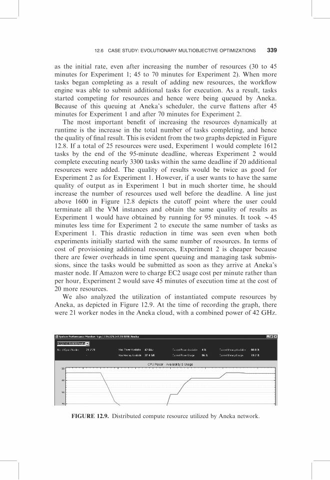
We also analyzed the utilization of instantiated compute resources byAneka, as depicted in Figure 12.9. At the time of recording the graph, therewere 21 worker nodes in the Aneka cloud, with a combined power of 42 GHz.
FIGURE 12.9. Distributed compute resource utilized by Aneka network.
12.6 CASE STUDY: EVOLUTIONARY MULTIOBJECTIVE OPTIMIZATIONS 339
The graph shows a steep rise in the system utilization (labeled as usage in thefigure) as tasks were submitted for execution. The compute power available(labeled as available) decreased to 4% with 80.8% memory available. Thisdecrease in utilization was due to the use of all the available resources forexecution of tasks submitted to Aneka by the workflow engine executing EMOworkflow.
12.7 VISIONARY THOUGHTS FOR PRACTITIONERS
The cloud computing paradigm is emerging and is being adopted at a rapidrate. Gartner ranks it at the top of the hype cycle for the year 2010 [29]. As thetechnology is being adopted by practitioners industry-wide, there are numerouschallenges to overcome. Moreover, these challenges could be addressed via arealistic vision of the cloud computing models of the near future. This sectiondiscusses some of them.
Software and service giants such as Google, Amazon, and Microsoft ownlarge data centers for providing a variety of cloud services to customers. Theseindependent and disparate initiatives would eventually lead to an interconnec-tion model where users can choose a combination of services from differentproviders in their applications. Our vision provides an entity responsible forbrokerage of resources across different cloud providers, termed the marketmaker [16]. These inter-cloud environments would then facilitate executions ofworkflow applications at distributed data centers. Large scientific experimentswould then be able to use inter-cloud resources, brokered through the marketmaker.
The essence of using cloud services is to be able to dynamically scale theapplications running on top of it. Automating resource provisioning and VMinstance management in clouds based on multiobjectives (cost, time, and otherQoS parameters) can help achieve this goal. The automation process should betransparent to the end users who would just be interested in running workflowapplications under their time and budget constraints. Users would specifyeither flexible or tight deadline for the cost they pay for using cloud services. Itbecomes the responsibility of the workflow engine running in the cloud todynamically scale the application to satisfy multiple users0 request.
In order to facilitate fair but competitive use of cloud resources for workflowapplications, a service negotiation module must be in place. This entity wouldnegotiate with multiple service providers to match users0 requirements to aservice provider’s capabilities. Once a match is found, required resources canthen be allocated to the user application. A cloud market directory service isneeded to maintain a catalog of services from various cloud service providers.Data and their communication play a vital role in any data-intensive workflowapplication. When running such applications on clouds, storage and transfercosts need to be taken into account in addition to the execution cost. The rightchoice of compute location and storage service provider would result in
340 WORKFLOW ENGINE FOR CLOUDS
minimizing the total cost billed to a user. A cloud market maker could handlethese task and communication issues at the time of negotiation between variouscloud service providers.
12.8 FUTURE RESEARCH DIRECTIONS
In Section 12.7, we described some visions and inherent difficulties faced bypractitioners when using various cloud services. Drawing upon these visions,we list below some future research directions in the form of broad researchdirections:
� How to facilitate inter-cloud operations in terms of coherent dataexchange, task migration, and load balancing for workflow application.
� When and where to provision cloud resources so that workflow applica-tions can meet their deadline constraints and also remain within theirbudget.
� How to balance the use of cloud and local resources so that workflowapplications can meet their objectives.
� How to match workflow application requirements to any service provi-der’s capabilities when there are numerous vendors with similar capabil-ities in a cloud.
12.9 SUMMARY AND CONCLUSIONS
To summarize, we have presented a comprehensive description of usingworkflow engine in cloud computing environments. We discussed the limita-tions of existing workflow management systems and proposed changes thatneed to be incorporated when moving to clouds. We also described cloud toolsthat could help applications use cloud services.
To demonstrate a practical scenario of deploying a workflow engine inclouds, we described in detail our workflow management system and a.NET-based cloud computing platform, Aneka. We presented a case study of anevolutionary multiobjective optimization algorithm. By modeling this applica-tion in the form of a workflow, we obtained an order-of-magnitude improve-ment in the application runtime when compute resources were provisioned atruntime. Thousands of tasks were completed in a short period of time asadditional resources were provisioned, eventually decreasing the total runtimeof the application.
Based on our experience in using cloud services, we conclude that largeapplications can certainly benefit by using cloud resources. The key benefits arein terms of decreased runtime, on-demand resource provisioning, and ease ofresource management. However, these services come at a price whereby usershave to pay cloud service providers on the basis of the resource usage.
12.9 SUMMARY AND CONCLUSIONS 341
Although clouds offer many benefits, they can’t and will not replace grids.Clouds will augment grids. Users will use cloud services together with their in-house solutions (cluster/enterprise grids) to enhance the performance of theirapplications as and when needed.
ACKNOWLEDGMENTS
This work is partially supported through Australian Research Council (ARC)Discovery Project grant. We would like to thank Christian Vecchiola fromUniversity of Melbourne for his help in defining the EMO application. We alsothank Adam Barker for reviewing and providing feedback on this chapter.
REFERENCES
1. R. Buyya, S. Pandey, and C. Vecchiola, Cloudbus toolkit for market-oriented
cloud computing, in Proceedings of the 1st International Conference on Cloud
Computing (CloudCom 2009, Springer, Germany), Beijing, China, December 1�4,
2009.
2. J. Yu and R. Buyya, A taxonomy of workflow management systems for grid
computing, Journal of Grid Computing, 3(3�4):171�200, 2005.
3. DAGMan Application. http://www.cs.wisc.edu/condor/dagman/ (November
2009).
4. T. Tannenbaum, D. Wright, K. Miller, and M. Livny. Condor—A distributed job
scheduler, in Beowulf Cluster Computing with Linux, MIT Press, Cambridge, MA,
2002.
5. E. Deelman, J. Blythe, Y. Gil, C. Kesselman, G. Mehta, and K. Vahi. Mapping
abstract complex workflows onto grid environments, Journal of Grid Computing, 1:
25�39, 2003.
6. B. Ludascher, I. Altintas, C. Berkley, D. Higgins, E. Jaeger, M. Jones, E. A. Lee, J.
Tao, and Y. Zhao, Scientific workflow management and the Kepler system,
Concurrency and Computation: Practice and Experience, 18(10):1039�1065, 2006.
7. T. Oinn, M. Addis, J. Ferris, D. Marvin, M. Senger, M. Greenwood, T. Carver, K.
Glover, M. R. Pocock, A. Wipat, and P. Li, Taverna: A tool for the composition
and enactment of bioinformatics workflows, in Bioinformatics, 20(17): 3045�3054,
2004.
8. I. Foster and C. Kesselman (eds.), The Grid: Blueprint for a Future Computing
Infrastructure, Morgan Kaufmann Publishers, San Francisco, 1999.
9. R. Buyya, Economic-Based Distributed Resource Management and Scheduling for
GridComputing, PhDThesis,MonashUniversity,Melbourne,Australia,April 2002.
10. R. Buyya, D. Abramson, and J. Giddy, An economy driven resource management
architecture for global computational power grids, in Proceedings of the 7th
International Conference on Parallel and Distributed Processing Techniques and
Applications, Las Vegas, June 26�29, 2000.
342 WORKFLOW ENGINE FOR CLOUDS
11. E. Deelman, G. Singh, M. Livny, B. Berriman, and J. Good, The cost of doing
science on the cloud: the montage example, in Proceedings of the 2008 ACM/IEEE
Conference on Supercomputing, NJ, 2008, pp. 1�12.
12. S. Pandey, W. Voorsluys, M. Rahman, R. Buyya, J. Dobson, and K. Chiu, A grid
workflow environment for brain imaging analysis on distributed systems, Con-
currency and Computation: Practice and Experience, 21(16):2118�2139, 2009.
13. S. Venugopal, K. Nadiminti, H. Gibbins, and R. Buyya, Designing a resource
broker for heterogeneous grids, Software: Practice and Experience, 38(8): 793�825,
2008.
14. C. Vecchiola, X. Chu, and R. Buyya, Aneka: A software platform for .NET-based
cloud computing, in High Performance and Large Scale Computing, IOS Press,
Amsterdam, Netherlands, 2009.
15. J. Yu and R. Buyya, Scheduling scientific workflow applications with deadline and
budget constraints using genetic algorithms, Scientific Programming Journal, 14
(3�4): 217�230, 2006.
16. Suraj Pandey, Linlin Wu, Siddeswara Guru, and Rajkumar Buyya, A Particle
Swarm Optimization (PSO)-based Heuristic for Scheduling Workflow Applica-
tions in Cloud Computing Environments, Proceedings of the 24th IEEE Interna-
tional Conference on Advanced Information Networking and Applications (AINA
2010), Perth, Australia, April 20�23, pp. 400�407, 2010. � Best Paper Award.
17. I. Raicu, Y. Zhao, I. Foster, and A. Szalay, Accelerating large-scale data
exploration through data diffusion, in Proceedings of the 2008 International
Workshop on Data-Aware Distributed Computing, ACM, 2008, pp. 9�18.
18. C. Vecchiola, S. Pandey, and R. Buyya, High-performance cloud computing: A
view of scientific applications, in Proceedings of the 10th International Symposium
on Pervasive Systems, Algorithms and Networks Kaohsiung, Taiwan, December
14�16, 2009.
19. Google AppEngine, http://code.google.com/appengine/ (November 2009).
20. Windows Azure Platform, http://www.microsoft.com/windowsazure/window
sazure/ (November 2009).
21. Standard ECMA-335, http://www.ecma-international.org/publications/standards/
Ecma-335.htm (November 2009).
22. C. Jin and R. Buyya, MapReduce programming model for .NET-based cloud
computing, in Proceedings of the 15th International European Parallel Computing
Conference, Delft, The Netherlands, August 25�28, 2009.
23. K. Czajkowski, S. Fitzgerald, I. Foster, and C. Kesselman, Grid information
services for distributed resource sharing, in 10th IEEE International Symposium
on High Performance Distributed Computing, Los Alamitos, CA, 7�9 August 2001.
24. R. Wolski, N. T. Spring, and J. Hayes. The network weather service: A distributed
resource performance forecasting service for metacomputing, Future Generation
Computer Systems, 15(5�6):757�768, 1999.
25. F. Chang, J. Dean, S. Ghemawat, W. C. Hsieh, D. A. Wallach, M. Burrows, T.
Chandra, A. Fikes, and R. E. Gruber, Bigtable: A distributed storage system for
structured data, in Proceedings of the 7th USENIX Symposium on Operating
Systems Design and Implementation, Berkeley, CA, USENIX Association, 2006,
p. 15.
REFERENCES 343
26. S. Ghemawat, H. Gobioff, and S. T. Leung, The google file system, SIGOPS
Operating System Review, 37(5), 2003, 29�43.
27. C. Vecchiola, M. Kirley, and R. Buyya, Multi-objective problem solving with
offspring on enterprise clouds, in Proceedings of the 10th International Conference
on High-Performance Computing in Asia-Pacific Region (HPC Asia 2009), Kaoh-
siung, Taiwan, March 2�5, 2009.
28. IBM TSpaces, http://www.almaden.ibm.com/cs/tspaces/ (November 2009).
29. Gartner’s Hype Cycle for 2009. http://www.gartner.com/technology/research/
hype-cycles/index.jsp (Accessed October, 2010).
344 WORKFLOW ENGINE FOR CLOUDS
Related Documents