BALOCHISTAN UNIVERSITY OF INFORMATION TECHNOLOGY, ENGINEERING & MANAGEMENT SCIENCES

Wireless power transmission via resonance coupling.
Jul 16, 2015
Welcome message from author
This document is posted to help you gain knowledge. Please leave a comment to let me know what you think about it! Share it to your friends and learn new things together.
Transcript
BALOCHISTAN UNIVERSITY OF INFORMATION TECHNOLOGY, ENGINEERING & MANAGEMENT SCIENCES
Group Members:
12/7/20142
Electronics
Engineering
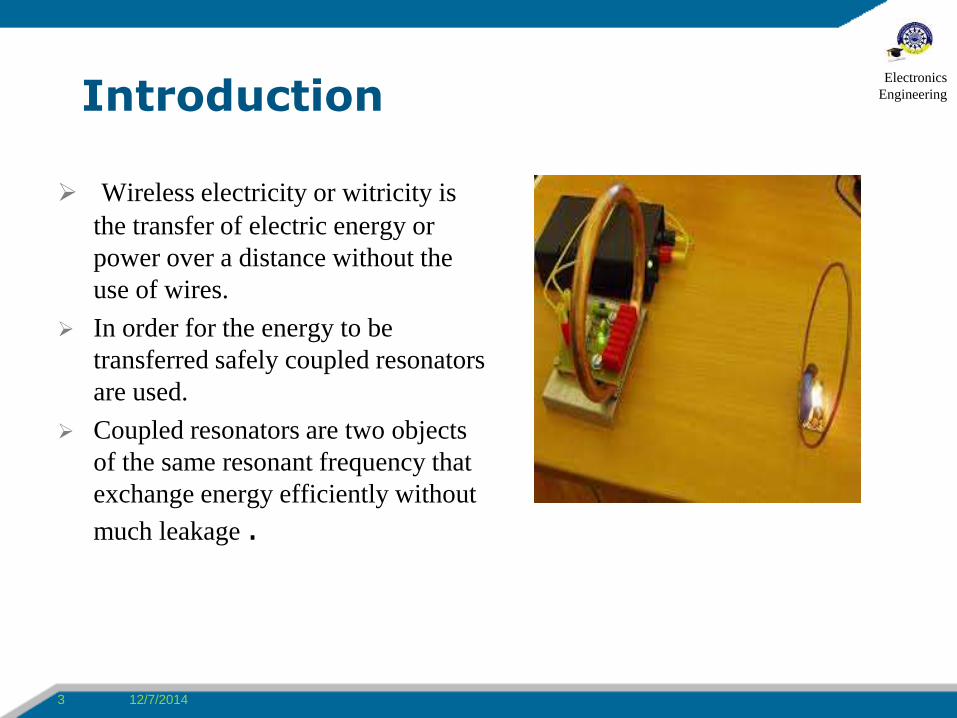
Introduction
Wireless electricity or witricity is
the transfer of electric energy or
power over a distance without the
use of wires.
In order for the energy to be
transferred safely coupled resonators
are used.
Coupled resonators are two objects
of the same resonant frequency that
exchange energy efficiently without
much leakage .
12/7/20143
Electronics
Engineering
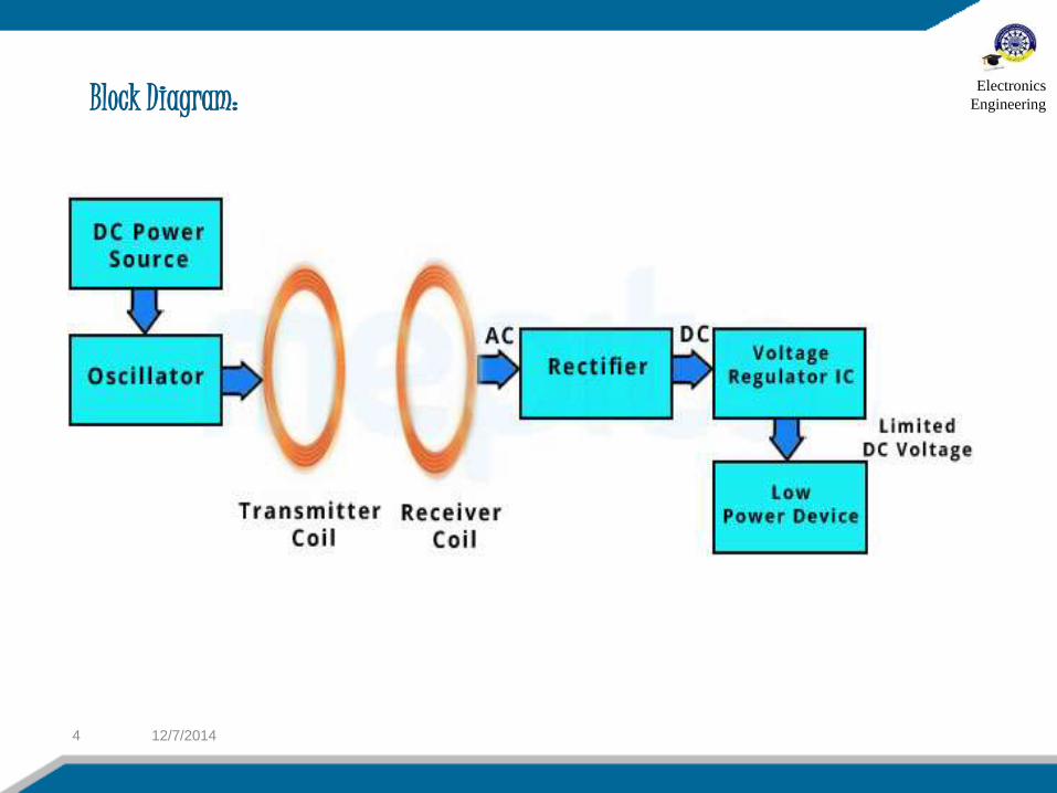
Block Diagram:
12/7/20144
Electronics
Engineering
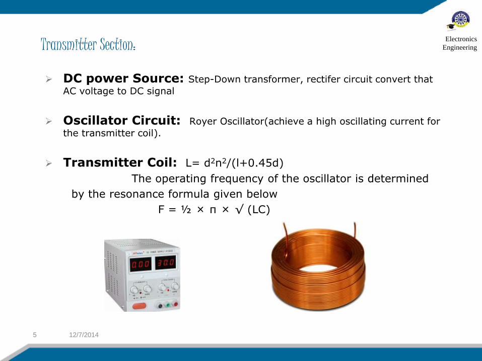
Transmitter Section:
DC power Source: Step-Down transformer, rectifer circuit convert that
AC voltage to DC signal
Oscillator Circuit: Royer Oscillator(achieve a high oscillating current for
the transmitter coil).
Transmitter Coil: L= d2n2/(l+0.45d)
The operating frequency of the oscillator is determined
by the resonance formula given below
F = ½ × π × √ (LC)
12/7/20145
Electronics
Engineering
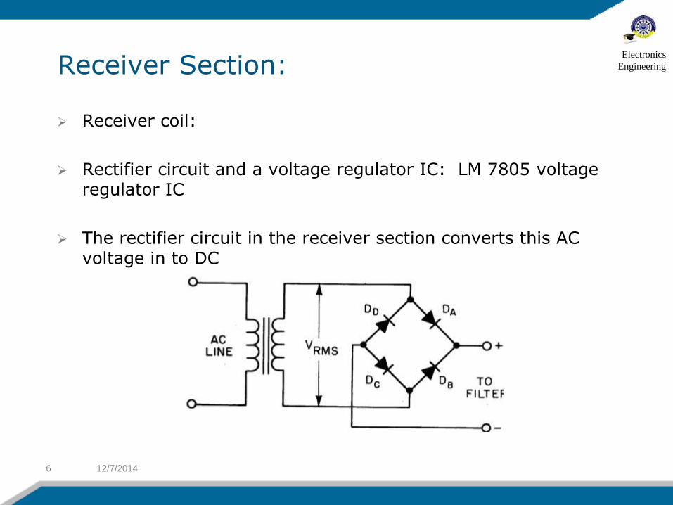
Receiver Section:
Receiver coil:
Rectifier circuit and a voltage regulator IC: LM 7805 voltage regulator IC
The rectifier circuit in the receiver section converts this AC voltage in to DC
12/7/20146
Electronics
Engineering
METHODS USED FOR WIRELESS POWER
TRANSMISSION
12/7/20147
Electronics
Engineering
Far Field Electricity Transmission Radio/Microwave Power transmission Laser Power Transmission Near Field Electricity Transmission Inductive Charging Evanescent/Resonant Wave Coupling
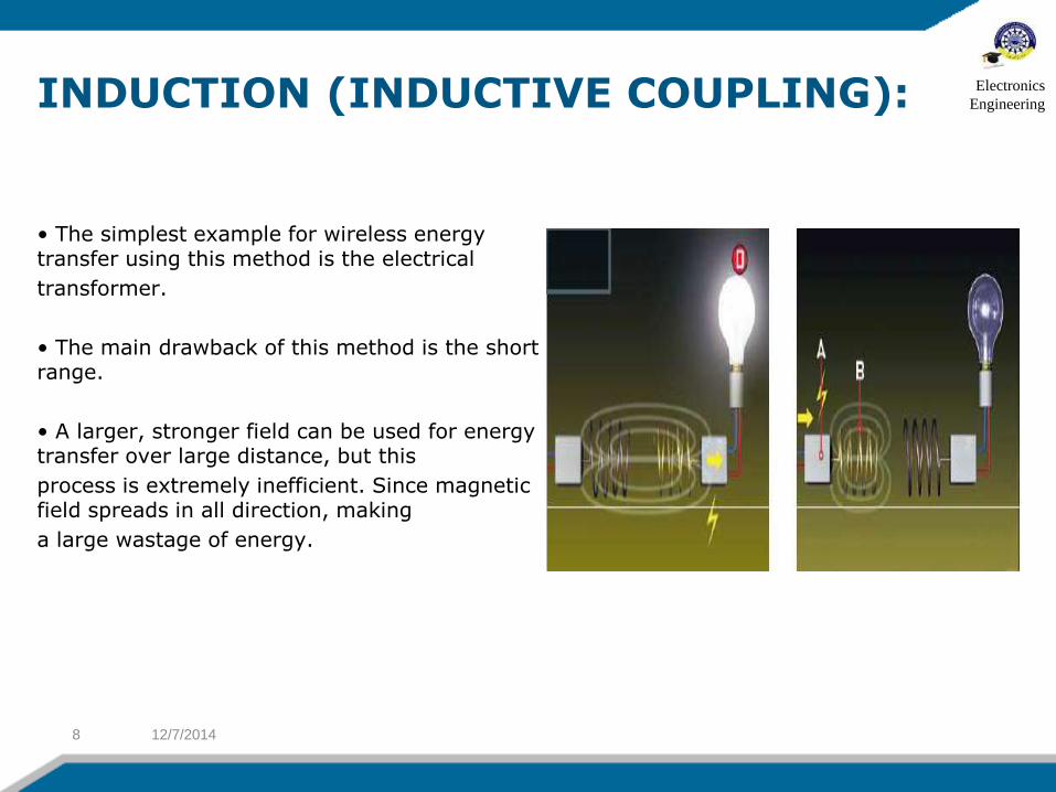
INDUCTION (INDUCTIVE COUPLING):
• The simplest example for wireless energy transfer using this method is the electrical
transformer.
• The main drawback of this method is the short range.
• A larger, stronger field can be used for energy transfer over large distance, but this
process is extremely inefficient. Since magnetic field spreads in all direction, making
a large wastage of energy.
12/7/20148
Electronics
Engineering
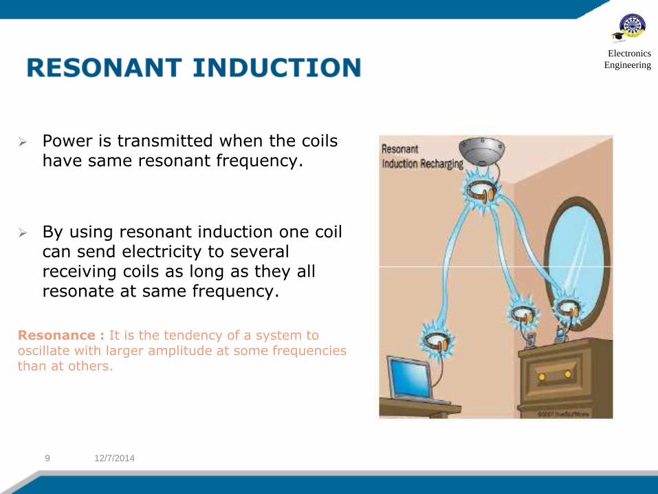
Power is transmitted when the coils have same resonant frequency.
By using resonant induction one coil can send electricity to several receiving coils as long as they all resonate at same frequency.
Resonance : It is the tendency of a system to oscillate with larger amplitude at some frequencies than at others.
12/7/20149
Electronics
Engineering
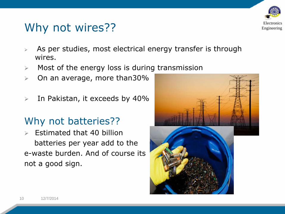
Why not wires??
As per studies, most electrical energy transfer is through wires.
Most of the energy loss is during transmission
On an average, more than30%
In Pakistan, it exceeds by 40%
Why not batteries?? Estimated that 40 billion
batteries per year add to the
e-waste burden. And of course its
not a good sign.
12/7/201410
Electronics
Engineering
Advantages and Hurdles
It can do away with costly grids and substations.
Homes and cities can be provided power wireless from a central transmission point.
Battery operated devices will never run out of power.
we can have cars that run non-stop with full battery charge.
We will never have to go to charging station.
Aircraft can fly nonstop with no need to refuel.
The future highway could have inductive coils imbedded in the road.
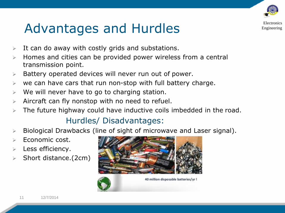
Hurdles/ Disadvantages: Biological Drawbacks (line of sight of microwave and Laser signal).
Economic cost.
Less efficiency.
Short distance.(2cm)
12/7/201411
Electronics
Engineering
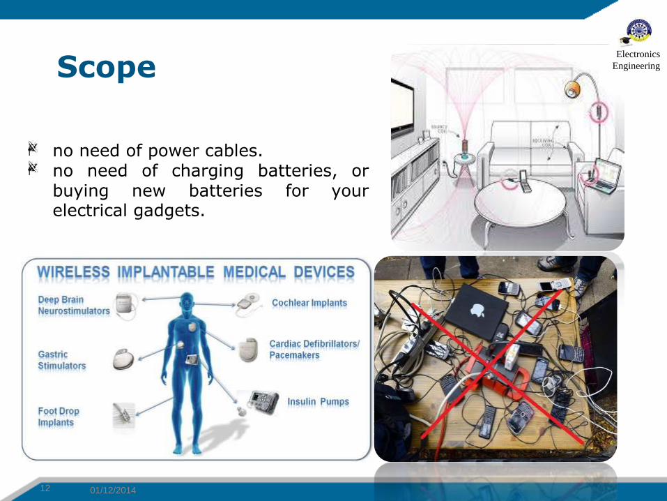
Scope
01/12/201412
no need of power cables.no need of charging batteries, orbuying new batteries for yourelectrical gadgets.
Electronics
Engineering

Gantt Chart
12/7/201413
Electronics
Engineering
References:
A next generation power transmission system”, International Journal of Computer Applications (0975 – 8887) (Volume 1 – No. 13)
Witricity
Peter Vaessen,” Wireless Power Transmission”, Leonardo Energy, September 2009 11/2/14 Wireless Power
www.wikipedia.com
http://www.sciencedirect.com/science/journals
12/7/201414
Electronics
Engineering
Electronics
Engineering
Questions
?
Related Documents