Wireless Dimmer Installation Guide Supported Model C4-DIM1-Z Wireless Dimmer Specifications and Supported Fixtures This Control4 ® Wireless Dimmer operates as part of a Control4 home-automation system to enable intelligent lighting control. It installs in a standard wall box using conventional wiring standards, and communicates with other devices through a wireless RF (radio frequency) connection. Power: • 120V +/- 10%, 50/60 Hz • 350mW Supported Load Types and Ratings: • 120 VAC 1000 W Incandescent (all types) • 120 VAC 1000 W Halogen (all types) • 120 VAC 1000 W Forward Phase Controlled Electronic Low Voltage (dimmable only) • 120 VAC 1000 W Forward Phase Controlled Fluorescent Light Fixtures (dimmable only) • 120 VAC 1000 VA Forward Phase Controlled Magnetic Low Voltage (all types with 70 per- cent or greater load factor) • Total minimum load must exceed 25W • This device can function with or without a neutral AC connection (see relevant wir- ing diagrams). However, when controlling Magnetic Low Voltage loads, a neutral wire connection is required. Operating Temperature: All load ratings are based on an ambient tempera- ture of 25 degrees Celsius. Volume: 5.0 Cubic inches Communications: ZigBee, IEEE 802.15.4, 2.4 GHz, 15-channel, spread spectrum radio Warnings and Considerations WARNING! Risk of Serious Injury, Death, or Property Damage or Loss. If you are unsure about any part of these instructions, consult a qualified electrician. PRÉVENANT : le Risque de Blessure Sérieuse, Mort, ou Dommage de Propriété ou Perte. Si vous êtes peu sûrs d’une partie de ces instructions, consultez un électricien qualifié.To reduce the risk of overheating and possible damage to this device and other equipment, DO NOT install to control a receptacle, a motor, or a transformer-operated appliance. WARNING! Risk of Electric Shock. Install in accordance with all regional, national, and local electrical codes. AVERTISSEMENT : Risque de Décharge électrique. Installez conformément à tous des codes électriques régionaux, nationaux et locaux. WARNING! Risk of Serious Injury, Death, or Property Damage or Loss. Install and use properly—as described in this document—to avoid danger of injury, death, or property damage or loss. PRÉVENANT : le Risque de Blessure Sérieuse, Mort, ou Dommage de Propriété ou Perte. Installez et utilisez correctement comme décrit dans ce document — pour éviter le danger de blessure, mort, ou dommage de propriété ou perte.If you are unsure about any part of these instructions, consult a qualified electrician. CAUTION! Risk of Overheating. To reduce the risk of overheating and possible damage to other equipment, do not install to control a receptacle or a motor-operated appliance. PRUDENCE : Risque du fait de surchauffer. Pour réduire le risque du fait de surchauffer et du dommage possible à d’autre équipement, n’installez pas pour contrôler un réceptacle, ou un appareil opéré de moteur. WARNING! Risk of Electrical Fire. Use this device only with copper or copper clad wire. Do not use aluminum wiring. This product has not been approved for use with aluminum wiring. AVERTISSEMENT : Risque de Feu Électrique. Utilisez cet artifice seulement avec le fil habillé couleur cuivre ou couleur cuivre. N’utilisez pas d’installation électrique en aluminium. Ce produit n’a pas été approuvé pour l’utilisation avec l’installation électrique en aluminium. IMPORTANT! This product generates heat during normal operation. IMPORTANT : Ce produit produit la chaleur pendant l’opération normale. IMPORTANT! Use or modification of this product in a manner not expressly approved by Control4 voids your warranty. Further, Control4 is NOT liable for any damage incurred with the misuse of this product. See “Limited 2 Year Warranty.” IMPORTANT : l’Utilisation ou la modification de ce produit dans une manière pas expressé- ment approuvée par les vides Control4 votre garantie. De plus, Control4 n’est pas responsable pour aucun dommage encouru avec le mauvais usage de ce produit. Voir “Limited 2 Year Warranty.” IMPORTANT! The range and performance of the wireless control system is highly dependent on the following: (1) distance between devices; (2) layout of the home; (3) walls separating devices; and (4) electrical equipment located near devices. IMPORTANT : la gamme et la performance du système de contrôle sans fil dépendent haute- ment de la chose suivante : (1) la distance entre les artifices; (2) la disposition de la maison; (3) les murs séparant des artifices; et (4) l’équipement électrique se positionnait près des artifices. Installation Instructions TURN OFF POWER by switching off the circuit breaker or removing the fuse and test that power is off before wiring! Ensure the Dimmer capacity matches the load requirements. In multi-Dimmer installations, a reduction of the Dimmer’s capac- ity is required to allow the Dimmers to be installed side-by-side in the same wall box. The Dimmer capacity depends on the number “ganged” in the wall box as follows: • 1 gang = 1000 W / VA maximum • 2 gang = 800 W / VA maximum per Dimmer • 3 or more gang = 600 W / VA maximum per Dimmer If installing in multi-gang scenarios, use pliers to remove the inner- side break-away tabs: Bend each tab back and forth until it breaks off. Remove the inner-side tabs ONLY on any device side that will be adjacent to another device. DO NOT remove tabs on any side that will become the outer side of a group of devices. Identify your wiring application and see the appropriate diagram in “Sample Wiring Configurations.” • Single-Location Scenario—Power Source at Wall Box • Single-Location Scenario—Power Source at Light Fixture • Two-Location Scenario—Power Source at Wall Box • Two-Location Scenario— Power Source at Light Fixture (on page 2) 1. 2. 3. 4. 5. Prepare the wires by removing the pre-cut insulation from the appropriate Dimmer leads. Wire insulation should be stripped back 1.6 cm (5/8”) from the wire end (as shown): Connect the Dimmer wires to the wall box wires using the wire nuts according to the relevant wiring diagram. See “Sample Wiring Configurations.” 6. Mount the Dimmer into the wall box by partially securing the wall box screws attached to the Dimmer. Ensure that the word “Top” on the Dimmer frame is facing up. Bend wires in a zigzag pattern so that they easily fold into the wall box. IMPORTANT! The Blue wire is not a traditional traveler: It cannot directly power a lighting load. It must only be used to provide power to another Control4 keypad. If you do not intend to use this wire, leave it capped. The blue wire is a “switched hot” wire that is connected internally to the Dimmer’s hot wire through the air-gap switch. Power is applied to the blue wire whenever the air-gap switch is closed. Thus, the blue wire is used to provide power to downstream key- pads in 3-way/4-way scenarios in order to ensure that all power to the load has been removed when the air-gap switch is open. See “Sample Wiring Configurations.” IMPORTANT : le fil Bleu n’est pas un voyageur traditionnel : Il ne peut pas directement le pouvoir une charge prenante. Il doit seulement être utilisé pour fournir le pouvoir d’un autre pavé numérique Control4. Si vous n’avez pas l’intention d’utiliser ce fil, le quitter couronné. Le fil bleu est un “” fil chaud échangé qui est raccordé à l’intérieur au fil chaud du variateur par le changement de trou aérien. Le pouvoir est appliqué au fil bleu chaque fois que le changement de trou aérien est fermé. Ainsi, le fil bleu est utilisé pour fournir le pouvoir d’en aval les pavés numériques dans 3-way/4-way les scénarios pour garantir que tout le pouvoir de la charge a été enlevé quand le changement de trou aérien est ouvert. Faites allusion “Sample Wiring Configurations.”

Welcome message from author
This document is posted to help you gain knowledge. Please leave a comment to let me know what you think about it! Share it to your friends and learn new things together.
Transcript
Wireless Dimmer Installation Guide
Supported Model C4-DIM1-Z Wireless Dimmer
Specifications and Supported FixturesThis Control4® Wireless Dimmer operates as part of a Control4 home-automation system to enable intelligent lighting control. It installs in a standard wall box using conventional wiring standards, and communicates with other devices through a wireless RF (radio frequency) connection.
Power: • 120V +/- 10%, 50/60 Hz• 350mW
Supported Load Types and Ratings:
• 120 VAC 1000 W Incandescent (all types)• 120 VAC 1000 W Halogen (all types)• 120 VAC 1000 W Forward Phase Controlled
Electronic Low Voltage (dimmable only)• 120 VAC 1000 W Forward Phase Controlled
Fluorescent Light Fixtures (dimmable only)• 120 VAC 1000 VA Forward Phase Controlled
Magnetic Low Voltage (all types with 70 per-cent or greater load factor)
• Total minimum load must exceed 25W• This device can function with or without a
neutral AC connection (see relevant wir-ing diagrams). However, when controlling Magnetic Low Voltage loads, a neutral wire connection is required.
Operating Temperature: All load ratings are based on an ambient tempera-ture of 25 degrees Celsius.
Volume: 5.0 Cubic inches
Communications: ZigBee, IEEE 802.15.4, 2.4 GHz, 15-channel, spread spectrum radio
Warnings and Considerations
WARNING! Risk of Serious Injury, Death, or Property Damage or Loss. If you are unsure aboutanypartoftheseinstructions,consultaqualifiedelectrician.PRÉVENANT : le Risque de Blessure Sérieuse, Mort, ou Dommage de Propriété ou Perte. Si vousêtespeusûrsd’unepartiedecesinstructions,consultezunélectricienqualifié.Toreducethe risk of overheating and possible damage to this device and other equipment, DO NOT install to control a receptacle, a motor, or a transformer-operated appliance.
Sample Wiring Configurations
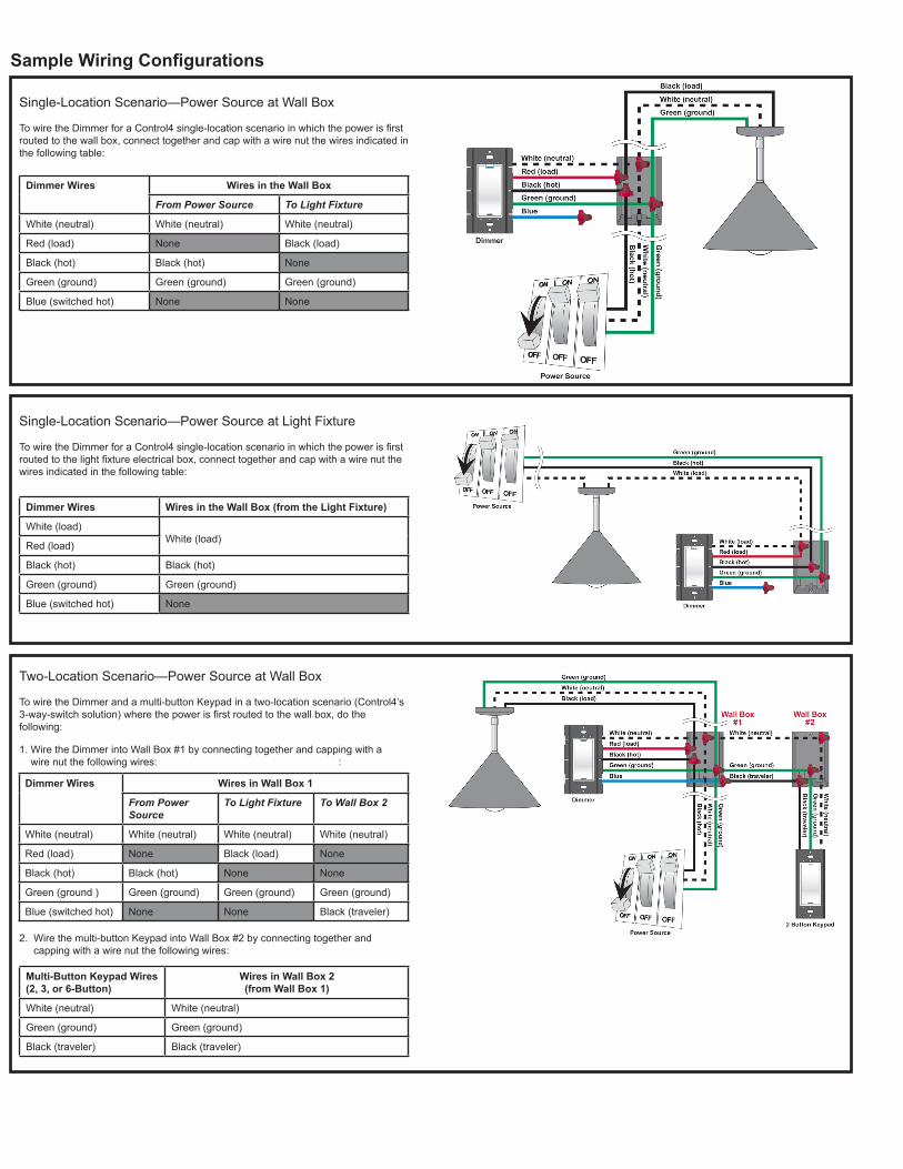
Single-Location Scenario—Power Source at Wall Box
TowiretheDimmerforaControl4single-locationscenarioinwhichthepowerisfirstrouted to the wall box, connect together and cap with a wire nut the wires indicated in the following table:
Dimmer Wires Wires in the Wall Box
From Power Source To Light Fixture
White (neutral) White (neutral) White (neutral)
Red (load) None Black (load)
Black (hot) Black (hot) None
Green (ground) Green (ground) Green (ground)
Blue (switched hot) None None
Single-Location Scenario—Power Source at Light Fixture TowiretheDimmerforaControl4single-locationscenarioinwhichthepowerisfirstroutedtothelightfixtureelectricalbox,connecttogetherandcapwithawirenutthewires indicated in the following table:
Dimmer Wires Wires in the Wall Box (from the Light Fixture)
White (load)White (load)
Red (load)
Black (hot) Black (hot)
Green (ground) Green (ground)
Blue (switched hot) None
Two-Location Scenario—Power Source at Wall Box
To wire the Dimmer and a multi-button Keypad in a two-location scenario (Control4’s 3-way-switchsolution)wherethepowerisfirstroutedtothewallbox,dothe following:
1. Wire the Dimmer into Wall Box #1 by connecting together and capping with a wire nut the following wires: :
Dimmer Wires Wires in Wall Box 1
From Power Source
To Light Fixture To Wall Box 2
White (neutral) White (neutral) White (neutral) White (neutral)
Red (load) None Black (load) None
Black (hot) Black (hot) None None
Green (ground ) Green (ground) Green (ground) Green (ground)
Blue (switched hot) None None Black (traveler)
Multi-Button Keypad Wires(2, 3, or 6-Button)
Wires in Wall Box 2 (from Wall Box 1)
White (neutral) White (neutral)
Green (ground) Green (ground)
Black (traveler) Black (traveler)
2. Wire the multi-button Keypad into Wall Box #2 by connecting together and capping with a wire nut the following wires:
WARNING! Risk of Electric Shock. Install in accordance with all regional, national, and local electrical codes.AVERTISSEMENT : Risque de Décharge électrique. Installez conformément à tous des codes électriques régionaux, nationaux et locaux.
WARNING! Risk of Serious Injury, Death, or Property Damage or Loss. Install and use properly—as described in this document—to avoid danger of injury, death, or property damage or loss.PRÉVENANT : le Risque de Blessure Sérieuse, Mort, ou Dommage de Propriété ou Perte. Installez et utilisez correctement comme décrit dans ce document — pour éviter le danger de blessure, mort, ou dommage de propriété ou perte.If you are unsure about any part of these instructions,consultaqualifiedelectrician.
CAUTION! Risk of Overheating. To reduce the risk of overheating and possible damage to other equipment, do not install to control a receptacle or a motor-operated appliance.PRUDENCE : Risque du fait de surchauffer. Pour réduire le risque du fait de surchauffer et du dommage possible à d’autre équipement, n’installez pas pour contrôler un réceptacle, ou un appareil opéré de moteur.
WARNING! Risk of Electrical Fire. Use this device only with copper or copper clad wire. Do not use aluminum wiring. This product has not been approved for use with aluminum wiring. AVERTISSEMENT : RisquedeFeuÉlectrique.Utilisezcetartificeseulementaveclefilhabillécouleur cuivre ou couleur cuivre. N’utilisez pas d’installation électrique en aluminium. Ce produit n’a pas été approuvé pour l’utilisation avec l’installation électrique en aluminium.
IMPORTANT! This product generates heat during normal operation.IMPORTANT : Ce produit produit la chaleur pendant l’opération normale.
IMPORTANT!UseormodificationofthisproductinamannernotexpresslyapprovedbyControl4 voids your warranty. Further, Control4 is NOT liable for any damage incurred with the misuse of this product. See “Limited 2 Year Warranty.”IMPORTANT :l’Utilisationoulamodificationdeceproduitdansunemanièrepasexpressé-ment approuvée par les vides Control4 votre garantie. De plus, Control4 n’est pas responsable pour aucun dommage encouru avec le mauvais usage de ce produit. Voir “Limited 2 Year Warranty.”IMPORTANT! The range and performance of the wireless control system is highly dependent on the following: (1) distance between devices; (2) layout of the home; (3) walls separating devices; and (4) electrical equipment located near devices.IMPORTANT : lagammeetlaperformancedusystèmedecontrôlesansfildépendenthaute-mentdelachosesuivante:(1)ladistanceentrelesartifices;(2)ladispositiondelamaison;(3)lesmursséparantdesartifices;et(4)l’équipementélectriquesepositionnaitprèsdesartifices.
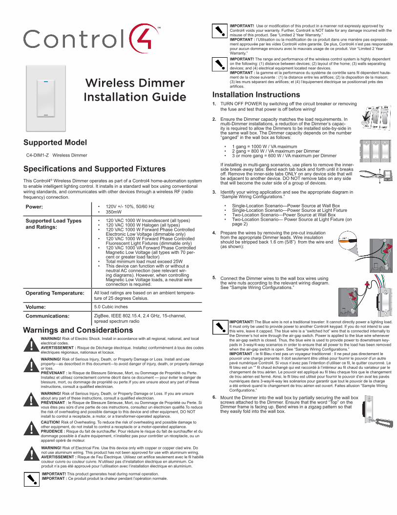
Installation InstructionsTURN OFF POWER by switching off the circuit breaker or removing the fuse and test that power is off before wiring!
Ensure the Dimmer capacity matches the load requirements. In multi-Dimmer installations, a reduction of the Dimmer’s capac-ity is required to allow the Dimmers to be installed side-by-side in the same wall box. The Dimmer capacity depends on the number “ganged” in the wall box as follows:
• 1 gang = 1000 W / VA maximum• 2 gang = 800 W / VA maximum per Dimmer• 3 or more gang = 600 W / VA maximum per Dimmer
If installing in multi-gang scenarios, use pliers to remove the inner-side break-away tabs: Bend each tab back and forth until it breaks off. Remove the inner-side tabs ONLY on any device side that will be adjacent to another device. DO NOT remove tabs on any side that will become the outer side of a group of devices.
Identify your wiring application and see the appropriate diagram in “SampleWiringConfigurations.”
• Single-Location Scenario—Power Source at Wall Box• Single-Location Scenario—Power Source at Light Fixture• Two-Location Scenario—Power Source at Wall Box• Two-Location Scenario— Power Source at Light Fixture (on
page 2)
1.
2.
3.
4.
5.
Prepare the wires by removing the pre-cut insulation from the appropriate Dimmer leads. Wire insulation should be stripped back 1.6 cm (5/8”) from the wire end (as shown):
Connect the Dimmer wires to the wall box wires using the wire nuts according to the relevant wiring diagram. See“SampleWiringConfigurations.”
6. Mount the Dimmer into the wall box by partially securing the wall box screws attached to the Dimmer. Ensure that the word “Top” on the Dimmer frame is facing up. Bend wires in a zigzag pattern so that they easily fold into the wall box.
IMPORTANT! The Blue wire is not a traditional traveler: It cannot directly power a lighting load. It must only be used to provide power to another Control4 keypad. If you do not intend to use this wire, leave it capped. The blue wire is a “switched hot” wire that is connected internally to the Dimmer’s hot wire through the air-gap switch. Power is applied to the blue wire whenever the air-gap switch is closed. Thus, the blue wire is used to provide power to downstream key-pads in 3-way/4-way scenarios in order to ensure that all power to the load has been removed whentheair-gapswitchisopen.See“SampleWiringConfigurations.”IMPORTANT : lefilBleun’estpasunvoyageurtraditionnel:Ilnepeutpasdirectementlepouvoir une charge prenante. Il doit seulement être utilisé pour fournir le pouvoir d’un autre pavénumériqueControl4.Sivousn’avezpasl’intentiond’utilisercefil,lequittercouronné.Lefilbleuestun“”filchaudéchangéquiestraccordéàl’intérieuraufilchaudduvariateurparlechangementdetrouaérien.Lepouvoirestappliquéaufilbleuchaquefoisquelechangementdetrouaérienestfermé.Ainsi,lefilbleuestutilisépourfournirlepouvoird’enavallespavésnumériques dans 3-way/4-way les scénarios pour garantir que tout le pouvoir de la charge a été enlevé quand le changement de trou aérien est ouvert. Faites allusion “Sample Wiring Configurations.”
Wireless Dimmer Installation Guide
Supported Model C4-DIM1-Z Wireless Dimmer
Specifications and Supported FixturesThis Control4® Wireless Dimmer operates as part of a Control4 home-automation system to enable intelligent lighting control. It installs in a standard wall box using conventional wiring standards, and communicates with other devices through a wireless RF (radio frequency) connection.
Power: • 120V +/- 10%, 50/60 Hz• 350mW
Supported Load Types and Ratings:
• 120 VAC 1000 W Incandescent (all types)• 120 VAC 1000 W Halogen (all types)• 120 VAC 1000 W Forward Phase Controlled
Electronic Low Voltage (dimmable only)• 120 VAC 1000 W Forward Phase Controlled
Fluorescent Light Fixtures (dimmable only)• 120 VAC 1000 VA Forward Phase Controlled
Magnetic Low Voltage (all types with 70 per-cent or greater load factor)
• Total minimum load must exceed 25W• This device can function with or without a
neutral AC connection (see relevant wir-ing diagrams). However, when controlling Magnetic Low Voltage loads, a neutral wire connection is required.
Operating Temperature: All load ratings are based on an ambient tempera-ture of 25 degrees Celsius.
Volume: 5.0 Cubic inches
Communications: ZigBee, IEEE 802.15.4, 2.4 GHz, 15-channel, spread spectrum radio
Warnings and Considerations
WARNING! Risk of Serious Injury, Death, or Property Damage or Loss. If you are unsure aboutanypartoftheseinstructions,consultaqualifiedelectrician.PRÉVENANT : le Risque de Blessure Sérieuse, Mort, ou Dommage de Propriété ou Perte. Si vousêtespeusûrsd’unepartiedecesinstructions,consultezunélectricienqualifié.Toreducethe risk of overheating and possible damage to this device and other equipment, DO NOT install to control a receptacle, a motor, or a transformer-operated appliance.
Sample Wiring Configurations
Single-Location Scenario—Power Source at Wall Box
TowiretheDimmerforaControl4single-locationscenarioinwhichthepowerisfirstrouted to the wall box, connect together and cap with a wire nut the wires indicated in the following table:
Dimmer Wires Wires in the Wall Box
From Power Source To Light Fixture
White (neutral) White (neutral) White (neutral)
Red (load) None Black (load)
Black (hot) Black (hot) None
Green (ground) Green (ground) Green (ground)
Blue (switched hot) None None
Single-Location Scenario—Power Source at Light Fixture TowiretheDimmerforaControl4single-locationscenarioinwhichthepowerisfirstroutedtothelightfixtureelectricalbox,connecttogetherandcapwithawirenutthewires indicated in the following table:
Dimmer Wires Wires in the Wall Box (from the Light Fixture)
White (load)White (load)
Red (load)
Black (hot) Black (hot)
Green (ground) Green (ground)
Blue (switched hot) None
Two-Location Scenario—Power Source at Wall Box
To wire the Dimmer and a multi-button Keypad in a two-location scenario (Control4’s 3-way-switchsolution)wherethepowerisfirstroutedtothewallbox,dothe following:
1. Wire the Dimmer into Wall Box #1 by connecting together and capping with a wire nut the following wires: :
Dimmer Wires Wires in Wall Box 1
From Power Source
To Light Fixture To Wall Box 2
White (neutral) White (neutral) White (neutral) White (neutral)
Red (load) None Black (load) None
Black (hot) Black (hot) None None
Green (ground ) Green (ground) Green (ground) Green (ground)
Blue (switched hot) None None Black (traveler)
Multi-Button Keypad Wires(2, 3, or 6-Button)
Wires in Wall Box 2 (from Wall Box 1)
White (neutral) White (neutral)
Green (ground) Green (ground)
Black (traveler) Black (traveler)
2. Wire the multi-button Keypad into Wall Box #2 by connecting together and capping with a wire nut the following wires:
WARNING! Risk of Electric Shock. Install in accordance with all regional, national, and local electrical codes.AVERTISSEMENT : Risque de Décharge électrique. Installez conformément à tous des codes électriques régionaux, nationaux et locaux.
WARNING! Risk of Serious Injury, Death, or Property Damage or Loss. Install and use properly—as described in this document—to avoid danger of injury, death, or property damage or loss.PRÉVENANT : le Risque de Blessure Sérieuse, Mort, ou Dommage de Propriété ou Perte. Installez et utilisez correctement comme décrit dans ce document — pour éviter le danger de blessure, mort, ou dommage de propriété ou perte.If you are unsure about any part of these instructions,consultaqualifiedelectrician.
CAUTION! Risk of Overheating. To reduce the risk of overheating and possible damage to other equipment, do not install to control a receptacle or a motor-operated appliance.PRUDENCE : Risque du fait de surchauffer. Pour réduire le risque du fait de surchauffer et du dommage possible à d’autre équipement, n’installez pas pour contrôler un réceptacle, ou un appareil opéré de moteur.
WARNING! Risk of Electrical Fire. Use this device only with copper or copper clad wire. Do not use aluminum wiring. This product has not been approved for use with aluminum wiring. AVERTISSEMENT : RisquedeFeuÉlectrique.Utilisezcetartificeseulementaveclefilhabillécouleur cuivre ou couleur cuivre. N’utilisez pas d’installation électrique en aluminium. Ce produit n’a pas été approuvé pour l’utilisation avec l’installation électrique en aluminium.
IMPORTANT! This product generates heat during normal operation.IMPORTANT : Ce produit produit la chaleur pendant l’opération normale.
IMPORTANT!UseormodificationofthisproductinamannernotexpresslyapprovedbyControl4 voids your warranty. Further, Control4 is NOT liable for any damage incurred with the misuse of this product. See “Limited 2 Year Warranty.”IMPORTANT :l’Utilisationoulamodificationdeceproduitdansunemanièrepasexpressé-ment approuvée par les vides Control4 votre garantie. De plus, Control4 n’est pas responsable pour aucun dommage encouru avec le mauvais usage de ce produit. Voir “Limited 2 Year Warranty.”IMPORTANT! The range and performance of the wireless control system is highly dependent on the following: (1) distance between devices; (2) layout of the home; (3) walls separating devices; and (4) electrical equipment located near devices.IMPORTANT : lagammeetlaperformancedusystèmedecontrôlesansfildépendenthaute-mentdelachosesuivante:(1)ladistanceentrelesartifices;(2)ladispositiondelamaison;(3)lesmursséparantdesartifices;et(4)l’équipementélectriquesepositionnaitprèsdesartifices.
Installation InstructionsTURN OFF POWER by switching off the circuit breaker or removing the fuse and test that power is off before wiring!
Ensure the Dimmer capacity matches the load requirements. In multi-Dimmer installations, a reduction of the Dimmer’s capac-ity is required to allow the Dimmers to be installed side-by-side in the same wall box. The Dimmer capacity depends on the number “ganged” in the wall box as follows:
• 1 gang = 1000 W / VA maximum• 2 gang = 800 W / VA maximum per Dimmer• 3 or more gang = 600 W / VA maximum per Dimmer
If installing in multi-gang scenarios, use pliers to remove the inner-side break-away tabs: Bend each tab back and forth until it breaks off. Remove the inner-side tabs ONLY on any device side that will be adjacent to another device. DO NOT remove tabs on any side that will become the outer side of a group of devices.
Identify your wiring application and see the appropriate diagram in “SampleWiringConfigurations.”
• Single-Location Scenario—Power Source at Wall Box• Single-Location Scenario—Power Source at Light Fixture• Two-Location Scenario—Power Source at Wall Box• Two-Location Scenario— Power Source at Light Fixture (on
page 2)
1.
2.
3.
4.
5.
Prepare the wires by removing the pre-cut insulation from the appropriate Dimmer leads. Wire insulation should be stripped back 1.6 cm (5/8”) from the wire end (as shown):
Connect the Dimmer wires to the wall box wires using the wire nuts according to the relevant wiring diagram. See“SampleWiringConfigurations.”
6. Mount the Dimmer into the wall box by partially securing the wall box screws attached to the Dimmer. Ensure that the word “Top” on the Dimmer frame is facing up. Bend wires in a zigzag pattern so that they easily fold into the wall box.
IMPORTANT! The Blue wire is not a traditional traveler: It cannot directly power a lighting load. It must only be used to provide power to another Control4 keypad. If you do not intend to use this wire, leave it capped. The blue wire is a “switched hot” wire that is connected internally to the Dimmer’s hot wire through the air-gap switch. Power is applied to the blue wire whenever the air-gap switch is closed. Thus, the blue wire is used to provide power to downstream key-pads in 3-way/4-way scenarios in order to ensure that all power to the load has been removed whentheair-gapswitchisopen.See“SampleWiringConfigurations.”IMPORTANT : lefilBleun’estpasunvoyageurtraditionnel:Ilnepeutpasdirectementlepouvoir une charge prenante. Il doit seulement être utilisé pour fournir le pouvoir d’un autre pavénumériqueControl4.Sivousn’avezpasl’intentiond’utilisercefil,lequittercouronné.Lefilbleuestun“”filchaudéchangéquiestraccordéàl’intérieuraufilchaudduvariateurparlechangementdetrouaérien.Lepouvoirestappliquéaufilbleuchaquefoisquelechangementdetrouaérienestfermé.Ainsi,lefilbleuestutilisépourfournirlepouvoird’enavallespavésnumériques dans 3-way/4-way les scénarios pour garantir que tout le pouvoir de la charge a été enlevé quand le changement de trou aérien est ouvert. Faites allusion “Sample Wiring Configurations.”
About this Document
Protected under U.S. Patents 5,982,103 and 5,905,442
Copyright ©2011 Control4. All rights reserved. Control4, the Control4 logo, the Control4 iQlogoandtheControl4certifiedlogoareregisteredtrademarksortrademarksofCon-trol4 Corporation in the United States and/or other countries. All other names and brands maybeclaimedasthepropertyoftheirrespectiveowners.Pricingandspecificationsaresubject to change without notice.
Part Number: 200-00035 Rev. E 4/28/2011
Operation and Configuration
TroubleshootingIf light does not turn on:• Ensure at least one LED on the face of the Dimmer is lit.• Ensure the light bulb is not burned out and is screwed in tightly.• Ensure that the circuit breaker is not turned OFF or tripped.• Checkforproperwiring(see“SampleWiringConfigurations”).• For help on the installation or operation of this product, email or call the Control4
Technical Support Center. Please provide your exact model number. Contact [email protected] or see the web site www.control4.com.
Limited 2-Year WarrantyFor complete warranty information, including details on consumer legal rights as well as warranty exclusions, visit www.control4.com/warranty.
Change Light Bulb or Fixture Default Behavior of RGB LEDs:
To cut power to the fixture: Top Bottom
Pull up on the Air Gap Mecha-nism and fully extend (about 0.3”) tocutpowertothelightfixture.
Not lit Not lit
Operate Dimmer Default Behavior of RGB LEDs:
To operate Dimmer: Top Bottom
Turn ON (full brightness): Tap top. Lit Not lit
Turn OFF: Tap bottom. Not lit Lit
Set dimming level: Press and hold the top or bottom until the desired lighting level is reached, then release.
Lit Not lit
Care and Cleaning
Do NOT paint the Dimmer or its wall plate.Do NOT use any chemical cleaners to clean the Dimmer.Clean the surface with a soft damp cloth as needed.
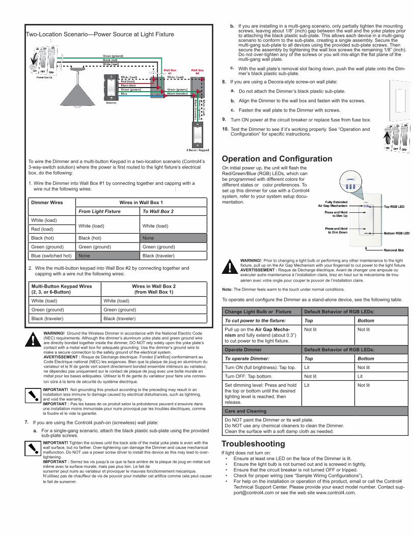
To wire the Dimmer and a multi-button Keypad in a two-location scenario (Control4’s 3-way-switchsolution)wherethepowerisfirstroutedtothelightfixture’selectricalbox, do the following:
1. Wire the Dimmer into Wall Box #1 by connecting together and capping with a wire nut the following wires: :
Dimmer Wires Wires in Wall Box 1
From Light Fixture To Wall Box 2
White (load)White (load) White (load)
Red (load)
Black (hot) Black (hot) None
Green (ground) Green (ground) Green (ground)
Blue (switched hot) None Black (traveler)
Multi-Button Keypad Wires(2, 3, or 6-Button)
Wires in Wall Box 2 (from Wall Box 1)
White (load) White (load)
Green (ground) Green (ground)
Black (traveler) Black (traveler)
2. Wire the multi-button keypad into Wall Box #2 by connecting together and capping with a wire nut the following wires:
Two-Location Scenario—Power Source at Light Fixture :
7. If you are using the Control4 push-on (screwless) wall plate:
a. For a single-gang scenario, attach the black plastic sub-plate using the provided sub-plate screws.IMPORTANT! Tighten the screws until the back side of the metal yoke plate is even with the wall surface, but no farther. Over-tightening can damage the Dimmer and cause mechanical malfunction. Do NOT use a power screw driver to install this device as this may lead to over-tightening.IMPORTANT :Serrezlesvisjusqu’àcequelafacearrièredelaplaquedejougenmétalsoitmême avec la surface murale, mais pas plus loin. Le fait desurserrer peut nuire au variateur et provoquer le mauvais fonctionnement mécanique. N’utilisezpasdechauffeurdevisdepouvoirpourinstallercetartificecommecelapeutcauserle fait de surserrer.
b.
c.
If you are installing in a multi-gang scenario, only partially tighten the mounting screws, leaving about 1/8” (inch) gap between the wall and the yoke plates prior to attaching the black plastic sub-plate. This allows each device in a multi-gang scenario to conform to the sub-plate, creating a single assembly. Secure the multi-gang sub-plate to all devices using the provided sub-plate screws. Then secure the assembly by tightening the wall box screws the remaining 1/8” (inch). Donotover-tightenanyofthescrewsoryouwillmis-aligntheflatplaneofthemulti-gang wall plate.
With the wall plate’s removal slot facing down, push the wall plate onto the Dim-mer’s black plastic sub-plate.
8.
9.
10.
If you are using a Decora-style screw-on wall plate:
a.
b.
c.
Do not attach the Dimmer’s black plastic sub-plate.
Align the Dimmer to the wall box and fasten with the screws.
Fasten the wall plate to the Dimmer with screws.
Regulatory Compliance
FCC/Industry Canada FCC ID: R33C4DIM1Z / Canada IC : 7848A-C4DIM1Z
This device complies with Part 15 of the FCC Rules. Operation is subject to the following two conditions: (1) this device may not cause harmful interference, and (2) this device must accept any interference received, including interference that may cause undesired operation of this device.
Son fonctionnement est soumis aux deux conditions suivantes: (1) cet appareil ne doit pas causer d’interférences nuisibles et (2) cet appareil doit accepter toute interférence reçue, y compris les inter-férences qui peuvent causer un mauvais fonctionnement du dispositif.
This Class B digital apparatus complies with Canada ICES-003.Cet appareil numérique de la classe B est conforme à la norme NMB-003 du Canada.
This equipment has been tested and found to comply with the limits for a Class B digital device, pursu-ant to Part 15 of the FCC Rules. These limits are designed to provide reasonable protection against harmful interference in a residential installation. This equipment generates, uses, and can radiate radio frequency energy and, if not installed and used in accordance with the instructions, may cause harmful interference to radio communications. However, there is no guarantee that interference will not occur in a particular installation. If this equipment does cause harmful interference to radio or television recep-tion, which can be determined by turning the equipment off and on, the user is encouraged to try to correct the interference by one or more of the following measures:
• Reorient or relocate the receiving antenna.• Increase the separation between the equipment and receiver.• Connect the equipment into an outlet on a circuit different from that to which the receiver is con-
nected.• Consult the dealer or an experienced radio/TV technician for help.
RecyclingFor recycling information, please go to www.control4.com/recycling.
WARNING! Ground the Wireless Dimmer in accordance with the National Electric Code (NEC) requirements. Although the dimmer’s aluminum yoke plate and green ground wire are directly bonded together inside the dimmer, DO NOT rely solely upon the yoke plate’s contact with a metal wall box for adequate grounding. Use the dimmer’s ground wire to make a secure connection to the safety ground of the electrical system.AVERTISSEMENT :RisquedeDéchargeélectrique.Fondez[l’artifice]conformémentauCode Électrique national (NEC) les exigences. Bien que la plaque de joug en aluminium du variateuretlefildegardevertsoientdirectementbondedensembleintérieursauvariateur,ne dépendez pas uniquement sur le contact de plaque de joug avec une boîte murale en métalpourlesbasesadéquates.Utilisezlefildegardeduvariateurpourfaireuneconnex-ionsûreàlaterredesécuritédusystèmeélectrique.
IMPORTANT! Not grounding this product according to the preceding may result in an installation less immune to damage caused by electrical disturbances, such as lightning, and void the warranty.IMPORTANT : Pas les bases de ce produit selon la précédence peuvent s’ensuivre dans une installation moins immunisée pour nuire provoqué par les troubles électriques, comme la foudre et le vide la garantie.
Turn ON power at the circuit breaker or replace fuse from fuse box.
Test the Dimmer to see if it’s working properly. See “Operation and Configuration”forspecificinstructions.
Oninitialpowerup,theunitwillflashtheRed/Green/Blue (RGB) LEDs, which can be programmed with different colors for different states or color preferences. To set up this dimmer for use with a Control4 system, refer to your system setup docu-mentation.
WARNING! Prior to changing a light bulb or performing any other maintenance to the light fixture,pullupontheAirGapMechanismwithyourfingernailtocutpowertothelightfixture.AVERTISSEMENT : Risque de Décharge électrique. Avant de changer une ampoule ou exécuter autre maintenance à l’installation claire, tirez en haut sur le mécanisme de trou aérien avec votre ongle pour couper le pouvoir de l’installation claire.
Note: The Dimmer feels warm to the touch under normal conditions.
TooperateandconfiguretheDimmerasastand-alonedevice,seethefollowingtable.
IMPORTANT!Anychangesormodificationsnotexpresslyapprovedbythepartyresponsiblefor compliance could void the user’s authority to operate this equipment.IMPORTANT : N’importequelschangementsoumodificationspasexpressémentapprouvéespar le parti responsable de l’acquiescement pourraient le vide l’autorité de l’utilisateur pour faire marcher cet équipement.
ETL Statement ETL Control Number: 3129831
This product has been tested by ETL and was found to comply with:
• UL 1472, First Edition, “Standard for Solid State Dimming Controls”• CSA C22.2 No. 184.1, First Edition, “Solid State Dimming Controls”
Protected under U.S. Patents D518,446, 7,335,845, 7,106,261, 7,336,463 and licensed under U.S. Patents 5,905,442 and 5,982,103
About this Document
Protected under U.S. Patents 5,982,103 and 5,905,442
Copyright ©2011 Control4. All rights reserved. Control4, the Control4 logo, the Control4 iQlogoandtheControl4certifiedlogoareregisteredtrademarksortrademarksofCon-trol4 Corporation in the United States and/or other countries. All other names and brands maybeclaimedasthepropertyoftheirrespectiveowners.Pricingandspecificationsaresubject to change without notice.
Part Number: 200-00035 Rev. E 4/28/2011
Operation and Configuration
TroubleshootingIf light does not turn on:• Ensure at least one LED on the face of the Dimmer is lit.• Ensure the light bulb is not burned out and is screwed in tightly.• Ensure that the circuit breaker is not turned OFF or tripped.• Checkforproperwiring(see“SampleWiringConfigurations”).• For help on the installation or operation of this product, email or call the Control4
Technical Support Center. Please provide your exact model number. Contact [email protected] or see the web site www.control4.com.
Limited 2-Year WarrantyFor complete warranty information, including details on consumer legal rights as well as warranty exclusions, visit www.control4.com/warranty.
Change Light Bulb or Fixture Default Behavior of RGB LEDs:
To cut power to the fixture: Top Bottom
Pull up on the Air Gap Mecha-nism and fully extend (about 0.3”) tocutpowertothelightfixture.
Not lit Not lit
Operate Dimmer Default Behavior of RGB LEDs:
To operate Dimmer: Top Bottom
Turn ON (full brightness): Tap top. Lit Not lit
Turn OFF: Tap bottom. Not lit Lit
Set dimming level: Press and hold the top or bottom until the desired lighting level is reached, then release.
Lit Not lit
Care and Cleaning
Do NOT paint the Dimmer or its wall plate.Do NOT use any chemical cleaners to clean the Dimmer.Clean the surface with a soft damp cloth as needed.
To wire the Dimmer and a multi-button Keypad in a two-location scenario (Control4’s 3-way-switchsolution)wherethepowerisfirstroutedtothelightfixture’selectricalbox, do the following:
1. Wire the Dimmer into Wall Box #1 by connecting together and capping with a wire nut the following wires: :
Dimmer Wires Wires in Wall Box 1
From Light Fixture To Wall Box 2
White (load)White (load) White (load)
Red (load)
Black (hot) Black (hot) None
Green (ground) Green (ground) Green (ground)
Blue (switched hot) None Black (traveler)
Multi-Button Keypad Wires(2, 3, or 6-Button)
Wires in Wall Box 2 (from Wall Box 1)
White (load) White (load)
Green (ground) Green (ground)
Black (traveler) Black (traveler)
2. Wire the multi-button keypad into Wall Box #2 by connecting together and capping with a wire nut the following wires:
Two-Location Scenario—Power Source at Light Fixture :
7. If you are using the Control4 push-on (screwless) wall plate:
a. For a single-gang scenario, attach the black plastic sub-plate using the provided sub-plate screws.IMPORTANT! Tighten the screws until the back side of the metal yoke plate is even with the wall surface, but no farther. Over-tightening can damage the Dimmer and cause mechanical malfunction. Do NOT use a power screw driver to install this device as this may lead to over-tightening.IMPORTANT :Serrezlesvisjusqu’àcequelafacearrièredelaplaquedejougenmétalsoitmême avec la surface murale, mais pas plus loin. Le fait desurserrer peut nuire au variateur et provoquer le mauvais fonctionnement mécanique. N’utilisezpasdechauffeurdevisdepouvoirpourinstallercetartificecommecelapeutcauserle fait de surserrer.
b.
c.
If you are installing in a multi-gang scenario, only partially tighten the mounting screws, leaving about 1/8” (inch) gap between the wall and the yoke plates prior to attaching the black plastic sub-plate. This allows each device in a multi-gang scenario to conform to the sub-plate, creating a single assembly. Secure the multi-gang sub-plate to all devices using the provided sub-plate screws. Then secure the assembly by tightening the wall box screws the remaining 1/8” (inch). Donotover-tightenanyofthescrewsoryouwillmis-aligntheflatplaneofthemulti-gang wall plate.
With the wall plate’s removal slot facing down, push the wall plate onto the Dim-mer’s black plastic sub-plate.
8.
9.
10.
If you are using a Decora-style screw-on wall plate:
a.
b.
c.
Do not attach the Dimmer’s black plastic sub-plate.
Align the Dimmer to the wall box and fasten with the screws.
Fasten the wall plate to the Dimmer with screws.
Regulatory Compliance
FCC/Industry Canada FCC ID: R33C4DIM1Z / Canada IC : 7848A-C4DIM1Z
This device complies with Part 15 of the FCC Rules. Operation is subject to the following two conditions: (1) this device may not cause harmful interference, and (2) this device must accept any interference received, including interference that may cause undesired operation of this device.
Son fonctionnement est soumis aux deux conditions suivantes: (1) cet appareil ne doit pas causer d’interférences nuisibles et (2) cet appareil doit accepter toute interférence reçue, y compris les inter-férences qui peuvent causer un mauvais fonctionnement du dispositif.
This Class B digital apparatus complies with Canada ICES-003.Cet appareil numérique de la classe B est conforme à la norme NMB-003 du Canada.
This equipment has been tested and found to comply with the limits for a Class B digital device, pursu-ant to Part 15 of the FCC Rules. These limits are designed to provide reasonable protection against harmful interference in a residential installation. This equipment generates, uses, and can radiate radio frequency energy and, if not installed and used in accordance with the instructions, may cause harmful interference to radio communications. However, there is no guarantee that interference will not occur in a particular installation. If this equipment does cause harmful interference to radio or television recep-tion, which can be determined by turning the equipment off and on, the user is encouraged to try to correct the interference by one or more of the following measures:
• Reorient or relocate the receiving antenna.• Increase the separation between the equipment and receiver.• Connect the equipment into an outlet on a circuit different from that to which the receiver is con-
nected.• Consult the dealer or an experienced radio/TV technician for help.
RecyclingFor recycling information, please go to www.control4.com/recycling.
WARNING! Ground the Wireless Dimmer in accordance with the National Electric Code (NEC) requirements. Although the dimmer’s aluminum yoke plate and green ground wire are directly bonded together inside the dimmer, DO NOT rely solely upon the yoke plate’s contact with a metal wall box for adequate grounding. Use the dimmer’s ground wire to make a secure connection to the safety ground of the electrical system.AVERTISSEMENT :RisquedeDéchargeélectrique.Fondez[l’artifice]conformémentauCode Électrique national (NEC) les exigences. Bien que la plaque de joug en aluminium du variateuretlefildegardevertsoientdirectementbondedensembleintérieursauvariateur,ne dépendez pas uniquement sur le contact de plaque de joug avec une boîte murale en métalpourlesbasesadéquates.Utilisezlefildegardeduvariateurpourfaireuneconnex-ionsûreàlaterredesécuritédusystèmeélectrique.
IMPORTANT! Not grounding this product according to the preceding may result in an installation less immune to damage caused by electrical disturbances, such as lightning, and void the warranty.IMPORTANT : Pas les bases de ce produit selon la précédence peuvent s’ensuivre dans une installation moins immunisée pour nuire provoqué par les troubles électriques, comme la foudre et le vide la garantie.
Turn ON power at the circuit breaker or replace fuse from fuse box.
Test the Dimmer to see if it’s working properly. See “Operation and Configuration”forspecificinstructions.
Oninitialpowerup,theunitwillflashtheRed/Green/Blue (RGB) LEDs, which can be programmed with different colors for different states or color preferences. To set up this dimmer for use with a Control4 system, refer to your system setup docu-mentation.
WARNING! Prior to changing a light bulb or performing any other maintenance to the light fixture,pullupontheAirGapMechanismwithyourfingernailtocutpowertothelightfixture.AVERTISSEMENT : Risque de Décharge électrique. Avant de changer une ampoule ou exécuter autre maintenance à l’installation claire, tirez en haut sur le mécanisme de trou aérien avec votre ongle pour couper le pouvoir de l’installation claire.
Note: The Dimmer feels warm to the touch under normal conditions.
TooperateandconfiguretheDimmerasastand-alonedevice,seethefollowingtable.
IMPORTANT!Anychangesormodificationsnotexpresslyapprovedbythepartyresponsiblefor compliance could void the user’s authority to operate this equipment.IMPORTANT : N’importequelschangementsoumodificationspasexpressémentapprouvéespar le parti responsable de l’acquiescement pourraient le vide l’autorité de l’utilisateur pour faire marcher cet équipement.
ETL Statement ETL Control Number: 3129831
This product has been tested by ETL and was found to comply with:
• UL 1472, First Edition, “Standard for Solid State Dimming Controls”• CSA C22.2 No. 184.1, First Edition, “Solid State Dimming Controls”
Protected under U.S. Patents D518,446, 7,335,845, 7,106,261, 7,336,463 and licensed under U.S. Patents 5,905,442 and 5,982,103
Related Documents