Milling, plotting, engraving, drilling, grinding, dispensing, cutting and much more besides with... WinPC-NC USB ...the software that turns your standard PC into a universal stepper motor NC unit Version 2.50 April 2015 © Copyright Burkhard Lewetz, 2006-2015

Welcome message from author
This document is posted to help you gain knowledge. Please leave a comment to let me know what you think about it! Share it to your friends and learn new things together.
Transcript
Milling, plotting, engraving, drilling, grinding, dispensing, cutting and much more besideswith...
WinPC-NCUSB
...the software that turns your standard PC into a universal stepper motor NC unit
Version 2.50
April 2015
© Copyright Burkhard Lewetz, 2006-2015
WinPC-NC USB
Lawful purchase of the diskette and the manual conveys permission for one person to utilise the WinPC-NC control program. Copying the diskette and the manual or changing any of theindividual files or elements of the manual are forbidden. Furthermore any unauthorizedtransmission of the program or extracts of it will be legally prosecuted by all available means.
The authors reserve all rights to the programs and to the manual, in particular the copyright.
This control program has undergone extremely thorough testing. Nevertheless, it is impossible to give a guarantee for completely fault-free operation. Furthermore, no responsibility can beaccepted for damage caused as a result of using our program.
Despite the most strenuous efforts, it is never possible to completely eliminate all faults.Consequently, we would be grateful to receive feedback from users.
Please note that support assistance and reduced updates are only available for registeredcustomers. In order to be registered please send us a mail indicating version number andserial number (either noted on the CD or visible in the program window) as well as yourcomplete address.
Please register your licence !!!!
Burkhard Lewetz Hardware-Software Brückenstrasse 7D-88074 Meckenbeuren GermanyeMail [email protected] Homepage www.lewetz.de April 2015
MS-Windows is a registered trademark of the Microsoft Corporation.Other products mentioned by name are trademarks or registered trademarks of their correspondingcompanies.
2.500e
- 2 -
WinPC-NC USB
Table of contents The structure of this manual................................................................................................5Definitions...........................................................................................................................5Use of typography................................................................................................................6Different versions of WinPC-NC........................................................................................7
1. What can WinPC-NC do ? .............................................................................................8
2. First steps.........................................................................................................................122.1. Requirements to the PC hardware...........................................................................122.2. Installation...............................................................................................................122.3. Launching the program............................................................................................132.4. First steps and test moves........................................................................................152.5. Exiting WinPC-NC..................................................................................................16
3. Operating WinPC-NC.....................................................................................................173.1. Graphical display of the NC file..............................................................................173.2. Drop-down menus and function keys .....................................................................223.3. The individual menus..............................................................................................233.3.1. FILE menu ...........................................................................................................23
OPEN ...................................................................................................................24OPEN WITHOUT PARAMETERS ....................................................................24EDITOR................................................................................................................25EXIT ....................................................................................................................25
3.3.2. MOVE menu.........................................................................................................25START .................................................................................................................26START FROM.....................................................................................................27START SINGLE STEP........................................................................................28ZERO POINT XY and PARK..............................................................................28JOG ......................................................................................................................28JOYSTICK JOG ..................................................................................................34REFERENCE MOVE...........................................................................................35SELECT TOOL ..................................................................................................35
3.3.3. PARAMETERs menu...........................................................................................37SAVE/LOAD MACHINE SETUP.......................................................................38SAVE ...................................................................................................................38SAVE AS .............................................................................................................39LOAD ..................................................................................................................39
3.3.4. SPECIAL FUNCTIONS menu ............................................................................39SIGNAL TEST.....................................................................................................40MOTOR TEST ....................................................................................................41STATUS INFORMATION..................................................................................42JOYSTICK CALIBRATION................................................................................43CHECK POSITION .............................................................................................43RESTORE TO FACTORY SETTINGS...............................................................44TEACHIN.............................................................................................................44
3.3.5. HELP menu...........................................................................................................46TOPICS.................................................................................................................46DISCLAIMER......................................................................................................47
- 3 -
WinPC-NC USB
ABOUT WinPC-NC.............................................................................................47
4. 2D-CAM functions..........................................................................................................484.1. Overview..................................................................................................................484.2. Settings....................................................................................................................494.3. Example 1................................................................................................................524.4. Example 2................................................................................................................55
5. Parameter settings...........................................................................................................585.1. Tool management....................................................................................................585.2. Speeds......................................................................................................................665.3. Coordinates..............................................................................................................585.4. Data format and associated parameters....................................................................765.5. Miscellaneous parameters........................................................................................805.6. Ports.........................................................................................................................885.7. Signals and dwell times...........................................................................................895.8. Machine parameters ................................................................................................915.9. Macros.....................................................................................................................100
6. Initial start-up with the machine.....................................................................................1046.1. Connecting the machine...........................................................................................1046.2. Pin assignment LPT port at ncUSB.........................................................................1056.3. Determination of axis resolution.............................................................................1066.4. Determination of move direction ............................................................................1076.5. Adjustment of reference switches............................................................................1096.6. Sequence and direction of reference move..............................................................1106.7. Control of adjustments.............................................................................................1106.8. Additional steps.......................................................................................................111
7. Signal wizzard................................................................................................................1127.1. Using input and output signals................................................................................1127.2. Assignment of inputs...............................................................................................1137.3. Assignment of output liness.....................................................................................1157.4. Input signals available.............................................................................................1167.5. Output signals available...........................................................................................117
8. Additional information....................................................................................................1188.1. Interpreters...............................................................................................................1188.1.1. HPGL....................................................................................................................1188.1.2. MultiCAM............................................................................................................1208.1.3. Drilling..................................................................................................................1208.1.4. G code or DIN/ISO...............................................................................................1218.1.5. ISEL NCP.............................................................................................................1248.1.6. Postscript...............................................................................................................1258.1.7. DXF......................................................................................................................1258.2. Error messages.........................................................................................................1268.3. Special versions of WinPC-NC...............................................................................128
- 4 -
WinPC-NC USB
The structure of this manual ...This manual provides you with all the information needed for usingWinPC-NC. It is divided into individual chapters, the contents ofwhich are summarised below:
Chapter 1: Brief explanation about WinPC-NC, the possibilities for using it and the hardware requirements.
Chapter 2: Initial start-up procedure, description of how to install the program and how to adjust the initial specific parameters.
Chapter 3: More detailed descriptions of how to operate the program and the individual functions of WinPC-NC.
Chapter 4 : 2D-CAM functions for sorting and calculating a tool diameter compensation.
Chapter 5: Explanation of all parameters and the setting options.
Chapter 6: Initial start-up procedure step by step
Chapter 7: Information concerning definitions and adjustments ofinput/output signals
Chapter 8: Further technical information about the program, about the implemented NC format interpreters, error messages and special versions.
Definitions
Some of the terms used in this manual may require an explanation:
Job file A file with NC data which is read and processed by or WinPC-NC. Depending on the application, the file NC file may contain milling, plotting, drilling data or other
types of data.
Job process The process of reading and processing a job file and the resultant actuation of the machine.
Command An individual instruction in the job file which gives rise to actions by the machine or in WinPC-NC.
Button Mouse clickable field to activate a certain function
Checkbox Box for activating or deactivation a certain parameter or function, e. g. signals. An activated checkbox is marked with a cross.
- 5 -
WinPC-NC USB
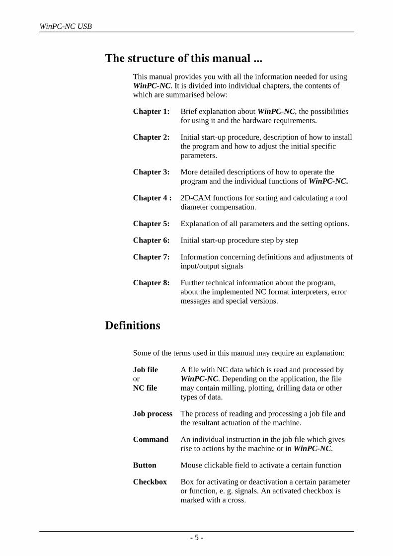
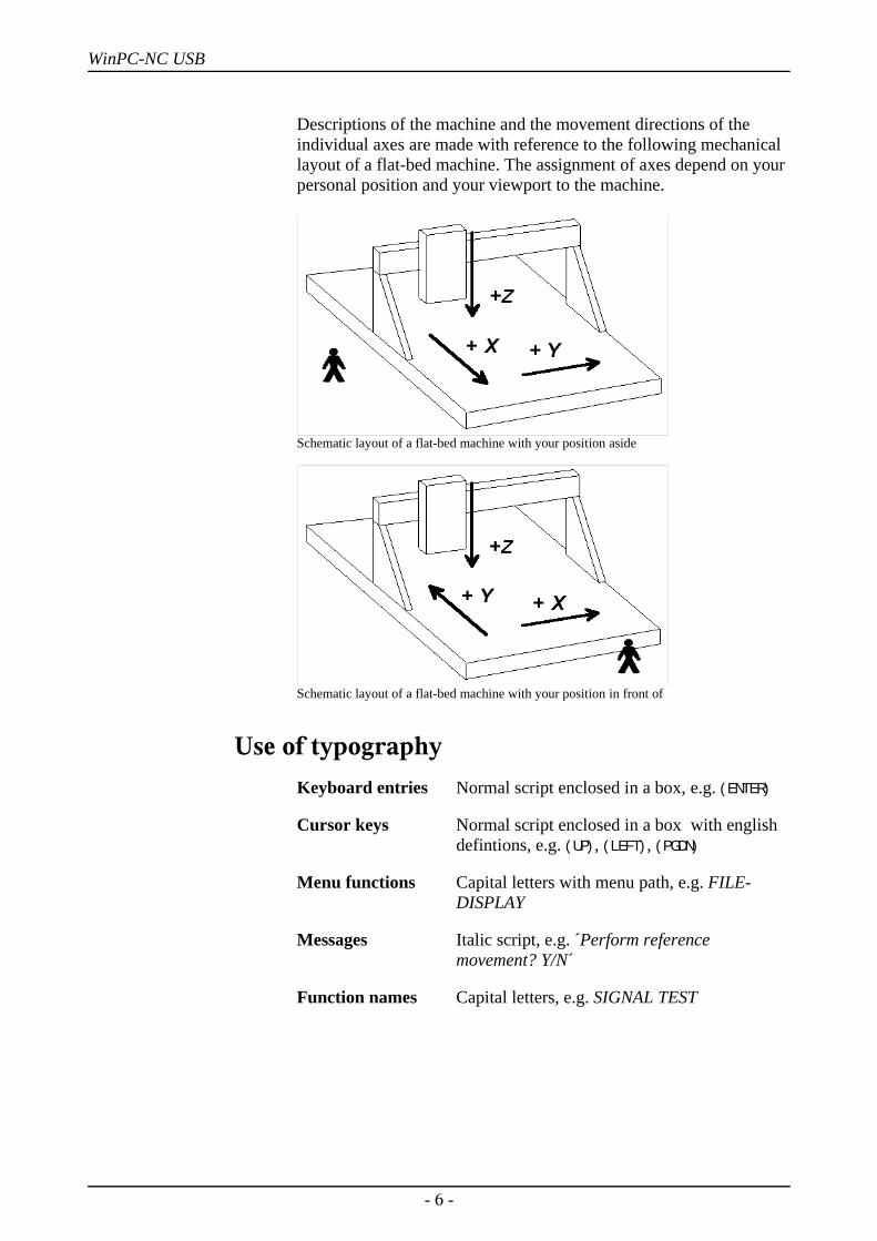
Descriptions of the machine and the movement directions of theindividual axes are made with reference to the following mechanicallayout of a flat-bed machine. The assignment of axes depend on yourpersonal position and your viewport to the machine.
Schematic layout of a flat-bed machine with your position aside
Schematic layout of a flat-bed machine with your position in front of
Use of typography Keyboard entries Normal script enclosed in a box, e.g. (ENTER)
Cursor keys Normal script enclosed in a box with english defintions, e.g. (UP), (LEFT), (PGDN)
Menu functions Capital letters with menu path, e.g. FILE-DISPLAY
Messages Italic script, e.g. ´Perform reference movement? Y/N´
Function names Capital letters, e.g. SIGNAL TEST
- 6 -
WinPC-NC USB
Different versions of WinPC-NCThe controlling program WinPC-NC is available in four differentversions.
Our lowcost program WinPC-NC Light offers all necessary functionsfor beginners, e.g. engraving, milling, drilling and PCB drilling ormanufacturing modelling parts.
WinPC-NC Economy is equipped with additional functions andoffers with up to four axes a lot of special functions and providessupport of extraordinary mechanical components. This programdisposes of much more format interpreters as the version forbeginners.
WinPC-NC Light and Economy are also available for SMC steppercards, i. e. motors are not controlled by clocking/direction signals butby SMC signals for well known stepper cards SMC800 andSMC1500.
The functions of WinPC-NC USB are equal to those of the Economyversion. However, with WinPC-NC USB the machine is controlledby a small enclosed USB module and not by an integrated LPT port.The module casing is equipped with 2 connectors which arecompatible to the LPT port.
WinPC-NC Professional is considered as industrial version and runsonly in combination with our external axes controller CPU and istherefore most qualified for all true realtime tasks. The program isfairly independent of windows speed and provides besides utmoststability and reliability additional professional technology functions.Furthermore, we can provide various housing types suitable forswitching cabinets according to the individual requirements.
WinPC-NC Starter is a very simple control program which isincluded to certain OEM machines as an addon software. It cannot bepurchased in separate and without machines. The simplefunctionality enables to create engravings, flat milled parts anddrilled PCB boards and leads in easy to learn steps to a saveoperation of the machine.
For comparing the different versions, please use the documentfunction table. It will provide detailed information concerningcapacity and potential operations.
- 7 -

WinPC-NC USB What can WinPC-NC do ?
1. What can WinPC-NC do ?
Universal program
Required hardwareaccessoriesenclosed
WinPC-NC is a software program which takes any standard personalcomputer and turns it into a universal NC control system for up to 4axes.
Win-PC-NC USB works with a small USB module called ncUSB.Due to this element CNC machines or stepper motor drives can bedirectly controlled. The USB module is equipped with 2 LPTcompatible ports which can be used in the same way as the PCinternal LPT ports of other WinPC-NC versions.
WinPC-NC USB requires a modern PC with at least 2 Ghz clock-pulse rate and 32 bit or 64 bit operating system Windows XP,Windows Vista, Windows 7 or Windows 8 and 8.1. (April 2015)
NcUSB module and cable set
By 4 stepper motor axes it is possible to realize any 3D mechanicsand to use them for various functions. Standard applications contain:
• Drilling • Milling• Plotting • Cutting foils• Grinding • Engraving plates• Dispensing • Sharpening coin dies
- 8 -
WinPC-NC USB What can WinPC-NC do ?
Extensiveparameters
Clearly structuredoperator interface
Runs on anymodern PC
The extensive range of options for setting parameters means theprogram can be adapted to almost all 2-4-axis machines.
WinPC-NC offers a well thought-out and modern operating conceptincorporating drop-down menus and a windows management systemwith mouse and keyboard operation. This makes it easy to learn andmaster the program.
Running WinPC-NC USB requires a modern standard PC with harddisk, USB ports, any kind of graphics card and a 32-bit Windowsoperating system. Notebooks and netbooks with correspondingequipment can also be used.
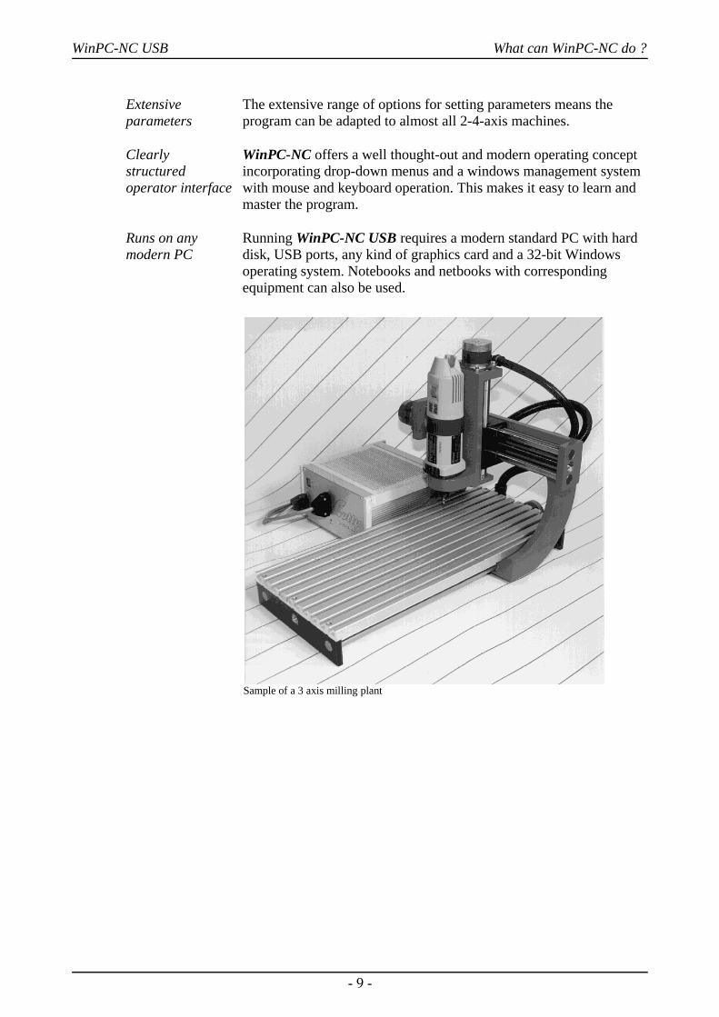
Sample of a 3 axis milling plant
- 9 -
WinPC-NC USB What can WinPC-NC do ?
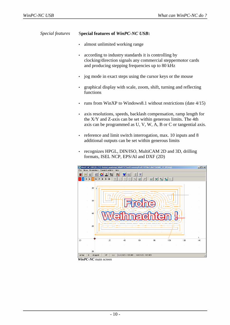
Special features Special features of WinPC-NC USB:
• almost unlimited working range
• according to industry standards it is controlling byclocking/direction signals any commercial steppermotor cardsand producing stepping frequencies up to 80 kHz
• jog mode in exact steps using the cursor keys or the mouse
• graphical display with scale, zoom, shift, turning and reflectingfunctions
• runs from WinXP to Windows8.1 without restrictions (date 4/15)
• axis resolutions, speeds, backlash compensation, ramp length forthe X/Y and Z-axis can be set within generous limits. The 4thaxis can be programmed as U, V, W, A, B or C or tangential axis.
• reference and limit switch interrogation, max. 10 inputs and 8additional outputs can be set within generous limits
• recognizes HPGL, DIN/ISO, MultiCAM 2D and 3D, drillingformats, ISEL NCP, EPS/AI and DXF (2D)
WinPC-NC main screen
- 10 -
WinPC-NC USB What can WinPC-NC do ?
• extensive tool management function, tools can be selectedindividually, colors can be set, repetition and feed functions
• Support of automatic tool changers with up to 10 magazinepositions
• CAM functions for cleaning up drawings, sorting by tool andposition and calculating tool diameter compensations
• speeds can be set between 0.01 and approx. 1000 mm/s
• high-performance integrated editor or external editor definable
• lots of external signals for synchronizing the procedure, e.g. startsignal, spindle speed reached, machine ready
• speed control of the drilling/milling spindles, counterclockwiserotation/clockwise rotation
• units of dimension can be set to mm, inch and mm/s, mm/min andinch/min
• multilingual, other languages can easily be added, 18 languagesselectable from menu (date 4/15)
• tool length measurement and compensation
• flexible macro language for running subroutines at various pointsin the program
• override for feed rate and spindle speed
• comfortable teachin function
• repetitions for mass production
• ..there are many other features besides these
- 11 -
WinPC-NC USB First steps
2. First steps
2.1. Requirements to hardwareWinPC-NC USB is able to perform a direct control of a connectedCNC machine and the drives belonging to it by the enclosed USBmodule ncUSB. The required USB driver and the software are to beinstalled on the computer.
A faultless operation is therefore only guaranteed with Personalcomputers with certain minimum of requirements.
• modern CPU with at least 2GHz clocking frequency
• 32 bit or 64 bit Windows operating system like Windows XP,Windows Vista, Windows 7 or Windows 8 or 8.1
• a direct USB 2.0 port, no passisve USB hub if possible
• standard graphical card, keyboard, mouse, hard disk and othercommon PC implements
• it is recommended to deactivate any kind of power savings, e. g.screen saver, hard disk shutdown and reduction of clock-pulse rate
Detailed information and tips for selecting the suitable computer canbe learned from further support information documents.
2.2. Installation
User-friendlyinstallation
WinPC-NC is installed using a user-friendly setup program. Pleaseinsert the disk into the drive and wait for automatic installation start.If the installation is not executed, please start the programSETUP.EXE directly from the CD.
The installation wizard then guides you through the entire procedure.
i WinPC-NC USB is delivered together with a separate USBmodule and cable or a built in USB hardware. Please connect itto the computer and machine after the software has beencompletely installed and thus the driver is loaded.
- 12 -
WinPC-NC USB First steps
Call up the README file to learn about important changes to theinformation in the manual. These changes are additional featuresincluded after the manual was written.
List of files The following files are installed to the target directory :
WINPCNC.EXE Control programWINPCNC.WPI or WTI Parameter fileWINPCNC.WPW or WTW Tool fileWINPCNC.WPO Settings for CAM functionsWINPCNC.HLP Help textsWINPCNC.LNG Messages and texts, multilingualWINPCNC.PDF this manual in PDF formatWCNCCON.DLL ncUSB driverREADME Latest changes to the manual*.DLL Some files needed in the system folders*.PLT *.SMM *.DIN Sample NC files*.NCP *.EPS *.DXF
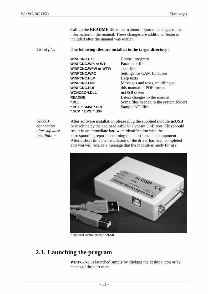
NcUSB connection after softwareinstallation
After software installation please plug the supplied module ncUSBor machine by the enclosed cable to a vacant USB port. This shouldresult in an immediate hardware identification with thecorresponding report concerning the latest installed component.After a short time the installation of the driver has been completedand you will receive a message that the module is ready for use.
Additional control module ncUSB
2.3. Launching the programWinPC-NC is launched simply by clicking the desktop icon or bymeans of the start menu.
- 13 -
WinPC-NC USB First steps
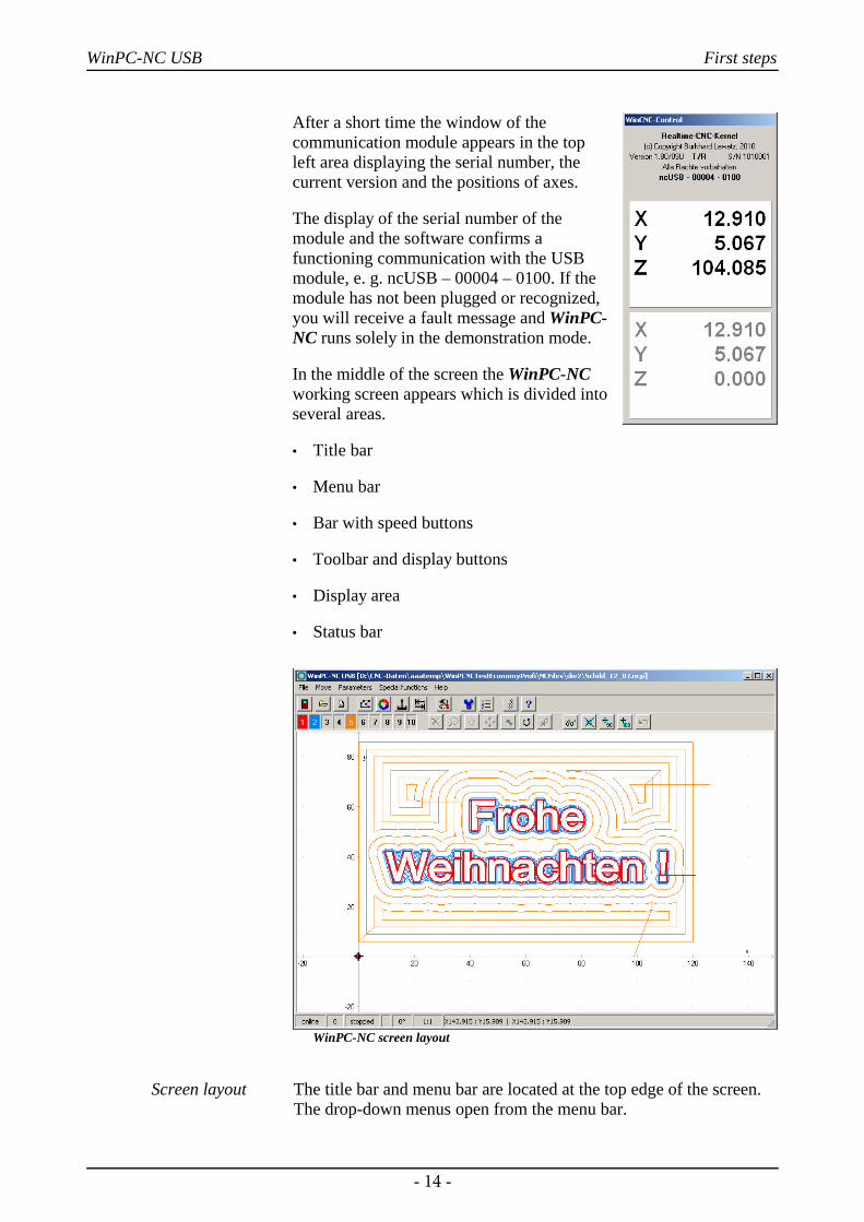
After a short time the window of thecommunication module appears in the topleft area displaying the serial number, thecurrent version and the positions of axes.
The display of the serial number of themodule and the software confirms afunctioning communication with the USBmodule, e. g. ncUSB – 00004 – 0100. If themodule has not been plugged or recognized,you will receive a fault message and WinPC-NC runs solely in the demonstration mode.
In the middle of the screen the WinPC-NCworking screen appears which is divided intoseveral areas.
• Title bar
• Menu bar
• Bar with speed buttons
• Toolbar and display buttons
• Display area
• Status bar
WinPC-NC screen layout
Screen layout The title bar and menu bar are located at the top edge of the screen.The drop-down menus open from the menu bar.
- 14 -
WinPC-NC USB First steps
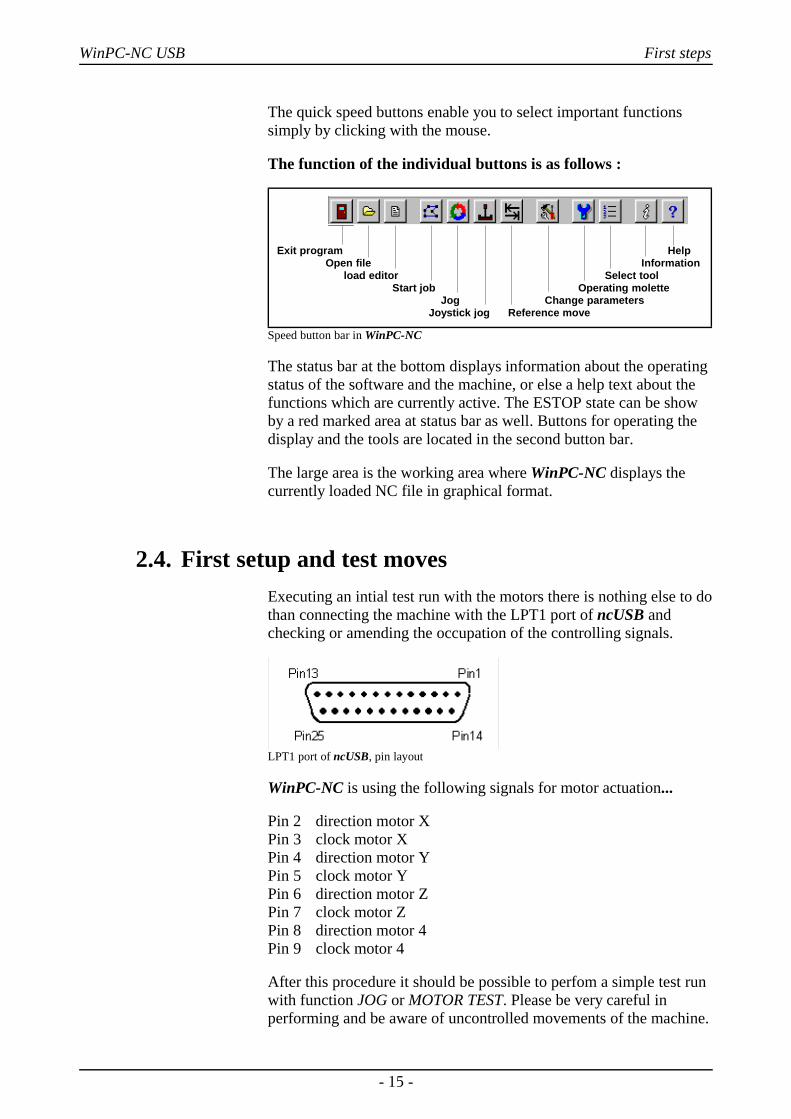
The quick speed buttons enable you to select important functionssimply by clicking with the mouse.
The function of the individual buttons is as follows :
Exit program Help Open file Information load editor Select tool Start job Operating molette Jog Change parameters Joystick jog Reference move
Speed button bar in WinPC-NC
The status bar at the bottom displays information about the operatingstatus of the software and the machine, or else a help text about thefunctions which are currently active. The ESTOP state can be showby a red marked area at status bar as well. Buttons for operating thedisplay and the tools are located in the second button bar.
The large area is the working area where WinPC-NC displays thecurrently loaded NC file in graphical format.
2.4. First setup and test movesExecuting an intial test run with the motors there is nothing else to dothan connecting the machine with the LPT1 port of ncUSB andchecking or amending the occupation of the controlling signals.
LPT1 port of ncUSB, pin layout
WinPC-NC is using the following signals for motor actuation...
Pin 2 direction motor XPin 3 clock motor XPin 4 direction motor YPin 5 clock motor YPin 6 direction motor ZPin 7 clock motor ZPin 8 direction motor 4Pin 9 clock motor 4
After this procedure it should be possible to perfom a simple test runwith function JOG or MOTOR TEST. Please be very careful inperforming and be aware of uncontrolled movements of the machine.
- 15 -

WinPC-NC USB First steps
Detailed instructions concerning start-up procedure are given in aseparate chapter.
2.5. Exiting WinPC-NCYou can exit WinPC-NC at any time by clicking the cross in the boxat the top right of the window, or by selecting EXIT from the FILEmenu.
- 16 -
WinPC-NC USB Operating WinPC-NC
3. Operating WinPC-NC
3.1. Graphical display of the NC file
Graphical previewof the NC files
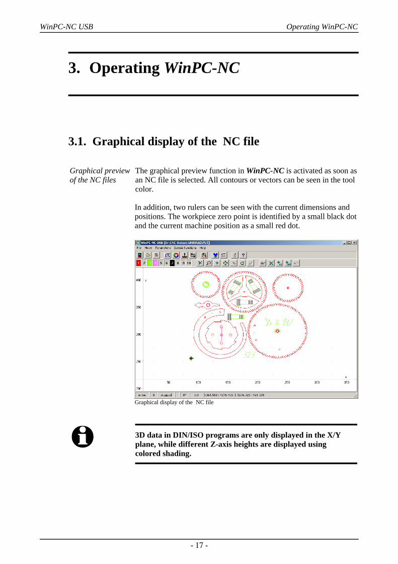
The graphical preview function in WinPC-NC is activated as soon asan NC file is selected. All contours or vectors can be seen in the toolcolor.
In addition, two rulers can be seen with the current dimensions andpositions. The workpiece zero point is identified by a small black dotand the current machine position as a small red dot.
Graphical display of the NC file
i 3D data in DIN/ISO programs are only displayed in the X/Yplane, while different Z-axis heights are displayed using colored shading.
- 17 -
WinPC-NC USB Operating WinPC-NC
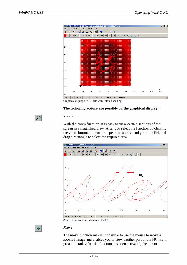
Graphical display of a 3D file with colored shading
The following actions are possible on the graphical display :
Zoom
With the zoom function, it is easy to view certain sections of thescreen in a magnified view. After you select the function by clickingthe zoom button, the cursor appears as a cross and you can click anddrag a rectangle to select the required area.
Zoom in the graphical display of the NC file
Move
The move function makes it possible to use the mouse to move azoomed image and enables you to view another part of the NC file ingreater detail. After the function has been activated, the cursor
- 18 -
WinPC-NC USB Operating WinPC-NC
appears as a hand. With it, you can click and drag any point to movethe image to where you want.
The movement track is displayed as a line while you are dragging.Once you release the mouse button, the graphic appears in the newposition to where you have moved it.
Display original size
Clicking this symbol restores the original size and position. Thisundoes all zoom and move actions.
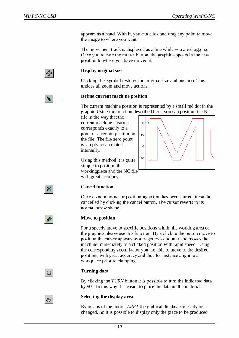
Define current machine position
The current machine position is represented by a small red dot in thegraphic.Using the function described here, you can position the NCfile in the way that thecurrent machine positioncorresponds exactly to apoint or a certain position inthe file. The file zero point is simply recalculatedinternally.
Using this method it is quitesimple to position theworkingpiece and the NC filewith great accuracy.
Cancel function
Once a zoom, move or positioning action has been started, it can becancelled by clicking the cancel button. The cursor reverts to itsnormal arrow shape.
Move to position
For a speedy move to specific positions within the working area orthe graphics please use this function. By a click to the button move toposition the cursor appears as a traget cross pointer and moves themachine immediately to a clicked position with rapid speed. Usingthe corresponding zoom factor you are able to move to the desiredpositions with great accuracy and thus for instance aligning aworkpiece prior to clamping.
Turning data
By clicking the TURN button it is possible to turn the indicated databy 90°. In this way it is easier to place the data on the material.
Selecting the display area
By means of the button AREA the grahical display can easily bechanged. So it is possible to display only the piece to be produced
- 19 -
WinPC-NC USB Operating WinPC-NC
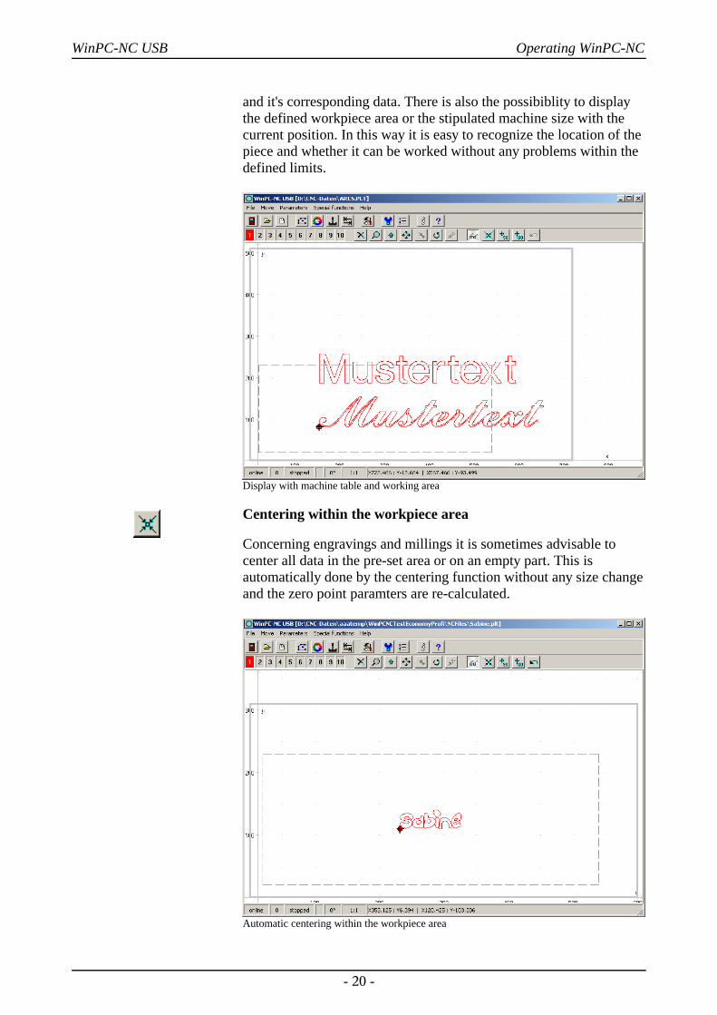
and it's corresponding data. There is also the possibiblity to displaythe defined workpiece area or the stipulated machine size with thecurrent position. In this way it is easy to recognize the location of thepiece and whether it can be worked without any problems within thedefined limits.
Display with machine table and working area
Centering within the workpiece area
Concerning engravings and millings it is sometimes advisable tocenter all data in the pre-set area or on an empty part. This isautomatically done by the centering function without any size changeand the zero point paramters are re-calculated.
Automatic centering within the workpiece area
- 20 -
WinPC-NC USB Operating WinPC-NC
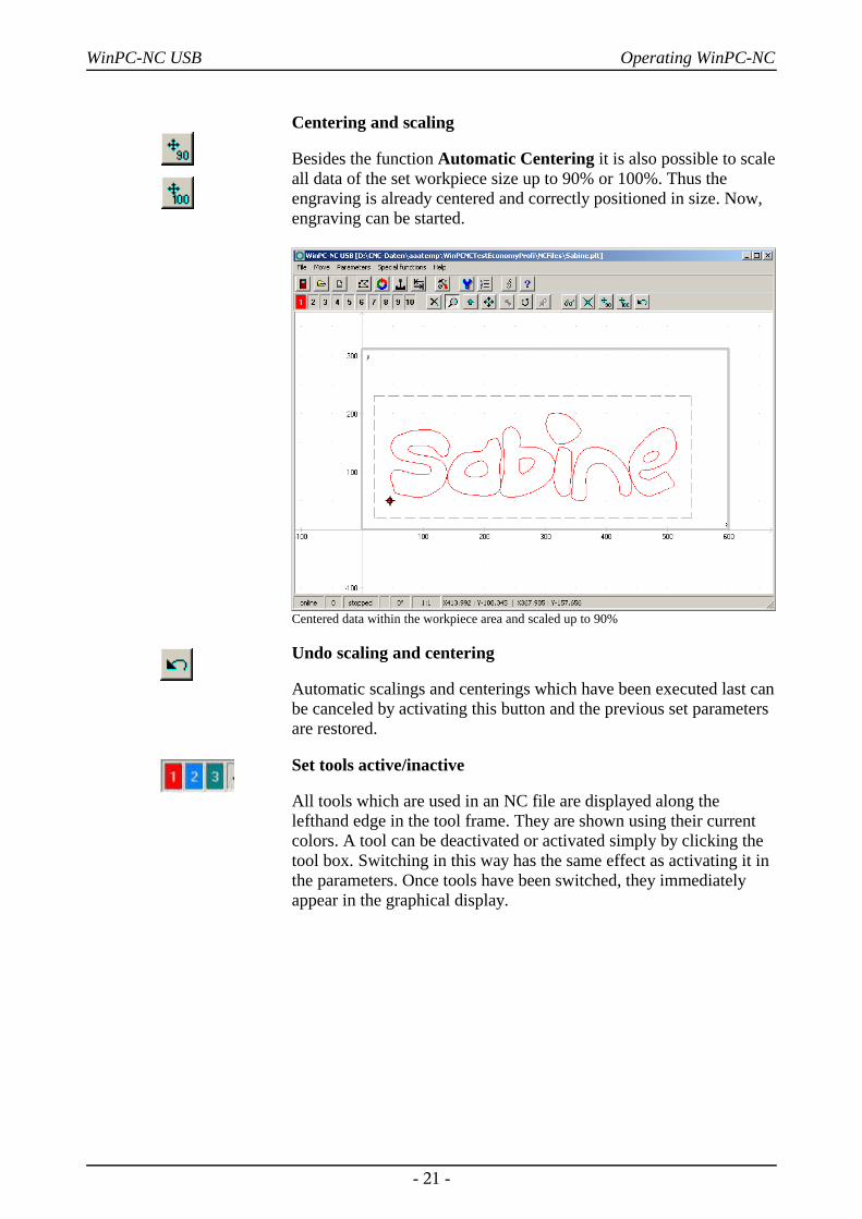
Centering and scaling
Besides the function Automatic Centering it is also possible to scaleall data of the set workpiece size up to 90% or 100%. Thus theengraving is already centered and correctly positioned in size. Now,engraving can be started.
Centered data within the workpiece area and scaled up to 90%
Undo scaling and centering
Automatic scalings and centerings which have been executed last canbe canceled by activating this button and the previous set parametersare restored.
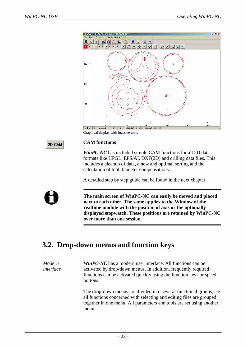
Set tools active/inactive
All tools which are used in an NC file are displayed along thelefthand edge in the tool frame. They are shown using their currentcolors. A tool can be deactivated or activated simply by clicking thetool box. Switching in this way has the same effect as activating it inthe parameters. Once tools have been switched, they immediatelyappear in the graphical display.
- 21 -
WinPC-NC USB Operating WinPC-NC
Graphical display with inactive tools
CAM functions
WinPC-NC has included simple CAM functions for all 2D dataformats like HPGL, EPS/AI, DXF(2D) and drilling data files. Thisincludes a cleanup of data, a new and optimal sorting and thecalculation of tool diameter compensations.
A detailed step by step guide can be found in the next chapter.
i The main screen of WinPC-NC can easily be moved and placednext to each other. The same applies to the Window of therealtime module with the position of axis or the optionallydisplayed stopwatch. These positions are retained by WinPC-NCover more than one session.
3.2. Drop-down menus and function keys
Modern interface
WinPC-NC has a modern user interface. All functions can beactivated by drop-down menus. In addition, frequently required functions can be activated quickly using the function keys or speedbuttons.
The drop-down menus are divided into several functional groups, e.g.all functions concerned with selecting and editing files are groupedtogether in one menu. All parameters and tools are set using anothermenu.
- 22 -
WinPC-NC USB Operating WinPC-NC
The menu system is opened or activated by clicking the menu item orpressing one of the shortcut keys for the individual menus.
Additionalfunction keys
Important functions can also be activated using function keys. Thefunction key assignment is fixed and indicated in the menufunctions.
The most important function keys are :
(F1) Activate the help system(F2) Load new NC file(shift-F2) Load parameter file(F3) Start job process(shift-F3) Start job process from defined point(F4) Move to XY origin(F5) Jog(shift-F5) Joystick jog(F7) Load active or new file into the editor(F8) Start reference move(F9) Move to parking position(F10) Open pull down menu
3.3. The individual menusThe following text describes all the menus and functions in detail.
Not all menu items are active all the time. Functions are sometimesunavailable, depending on the program status. For example, it is notpossible to use the joystick if it has not been defined in theparameters.
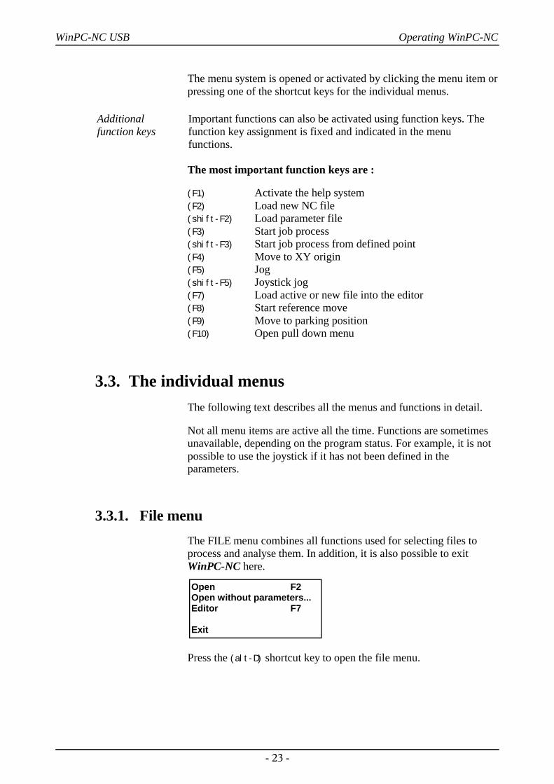
3.3.1. File menuThe FILE menu combines all functions used for selecting files toprocess and analyse them. In addition, it is also possible to exitWinPC-NC here.
Press the (alt-D) shortcut key to open the file menu.
- 23 -
Open F2Open without parameters...Editor F7
Exit
WinPC-NC USB Operating WinPC-NC
FILE-OPEN
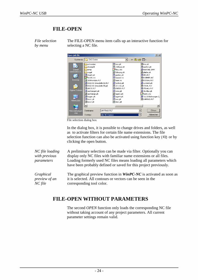
File selection by menu
The FILE-OPEN menu item calls up an interactive function forselecting a NC file.
File selection dialog box
In the dialog box, it is possible to change drives and folders, as wellas to activate filters for certain file name extensions. The fileselection function can also be activated using function key (F2) or byclicking the open button.
NC file loadingwith previousparameters
Graphical preview of an NC file
A preliminary selection can be made via filter. Optionally you candisplay only NC files with familiar name extensions or all files.Loading formerly used NC files means loading all parameters whichhave been probably defined or saved for this project previously.
The graphical preview function in WinPC-NC is activated as soon asit is selected. All contours or vectors can be seen in thecorresponding tool color.
FILE-OPEN WITHOUT PARAMETERSThe second OPEN function only loads the corresponding NC filewithout taking account of any project parameters. All currentparameter settings remain valid.
- 24 -
WinPC-NC USB Operating WinPC-NC
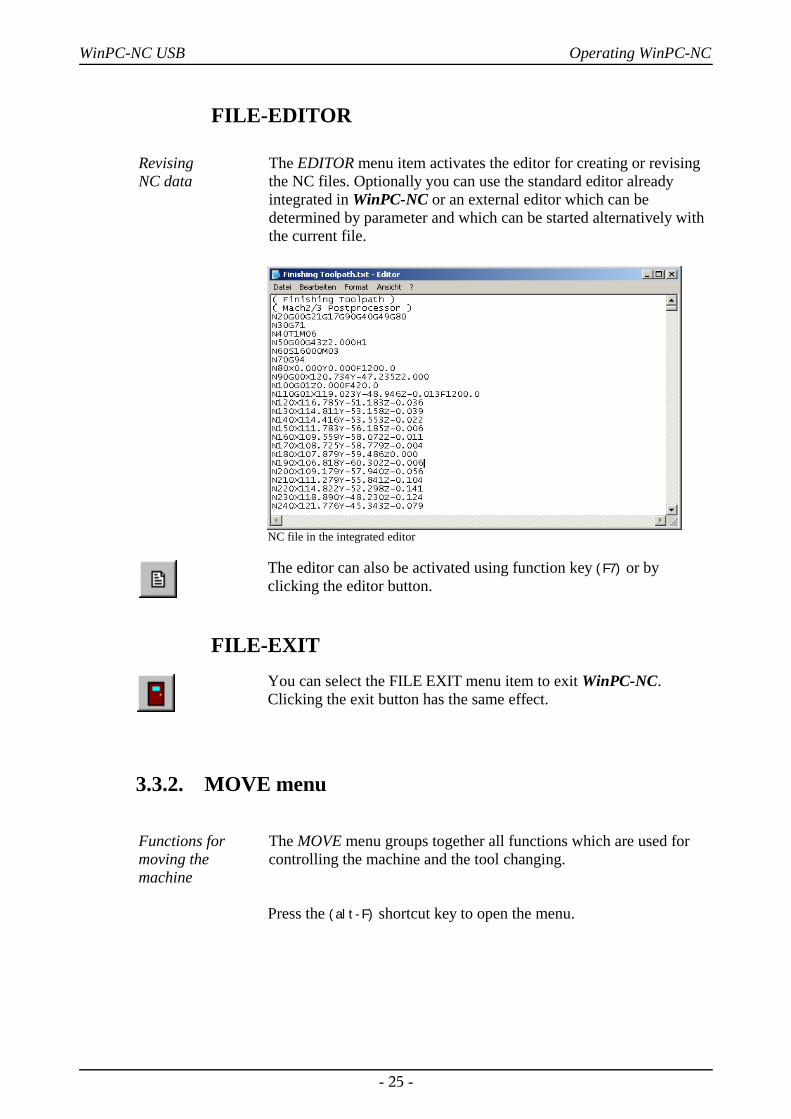
FILE-EDITOR
Revising NC data
The EDITOR menu item activates the editor for creating or revisingthe NC files. Optionally you can use the standard editor alreadyintegrated in WinPC-NC or an external editor which can bedetermined by parameter and which can be started alternatively withthe current file.
NC file in the integrated editor
The editor can also be activated using function key (F7) or byclicking the editor button.
FILE-EXITYou can select the FILE EXIT menu item to exit WinPC-NC.Clicking the exit button has the same effect.
3.3.2. MOVE menu
Functions formoving themachine
The MOVE menu groups together all functions which are used forcontrolling the machine and the tool changing.
Press the (alt-F) shortcut key to open the menu.
- 25 -
WinPC-NC USB Operating WinPC-NC
MOVE-STARTAfter a working file has been loaded, the START menu item can beused for processing the job. Pressing the (F3) key or clicking theSTART button has the same effect.
WinPC-NC controls the X and Y motors during move commands.The Z motor moves up and down during tool movement commands.All three axes or optional even four axes can move at the same timein 3D files.
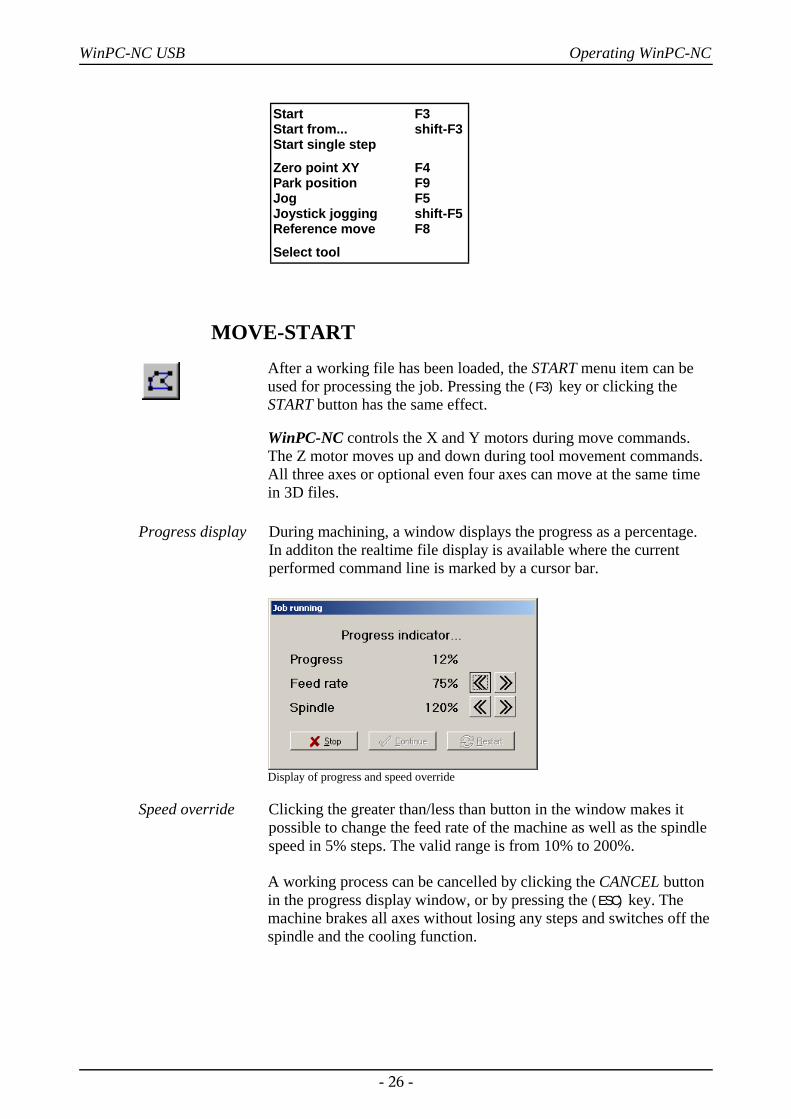
Progress display During machining, a window displays the progress as a percentage.In additon the realtime file display is available where the currentperformed command line is marked by a cursor bar.
Display of progress and speed override
Speed override Clicking the greater than/less than button in the window makes itpossible to change the feed rate of the machine as well as the spindlespeed in 5% steps. The valid range is from 10% to 200%.
A working process can be cancelled by clicking the CANCEL buttonin the progress display window, or by pressing the (ESC) key. Themachine brakes all axes without losing any steps and switches off thespindle and the cooling function.
- 26 -
Start F3Start from... shift-F3Start single step
Zero point XY F4 Park position F9Jog F5Joystick jogging shift-F5Reference move F8
Select tool
WinPC-NC USB Operating WinPC-NC
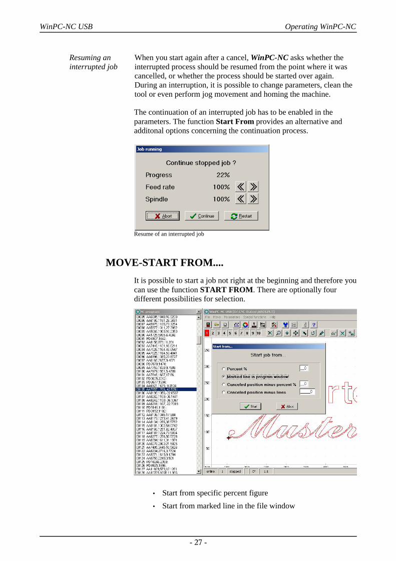
Resuming aninterrupted job
When you start again after a cancel, WinPC-NC asks whether theinterrupted process should be resumed from the point where it wascancelled, or whether the process should be started over again.During an interruption, it is possible to change parameters, clean thetool or even perform jog movement and homing the machine.
The continuation of an interrupted job has to be enabled in theparameters. The function Start From provides an alternative andadditonal options concerning the continuation process.
Resume of an interrupted job
MOVE-START FROM....It is possible to start a job not right at the beginning and therefore youcan use the function START FROM. There are optionally fourdifferent possibilities for selection.
• Start from specific percent figure• Start from marked line in the file window
- 27 -
WinPC-NC USB Operating WinPC-NC
• Start from previous interruption position less a percentfigure
• Start from previous interruption position less a number ofprogram lines in the file window
By starting the job WinPC-NC recalculates the initial point, moves toit and continues the job.
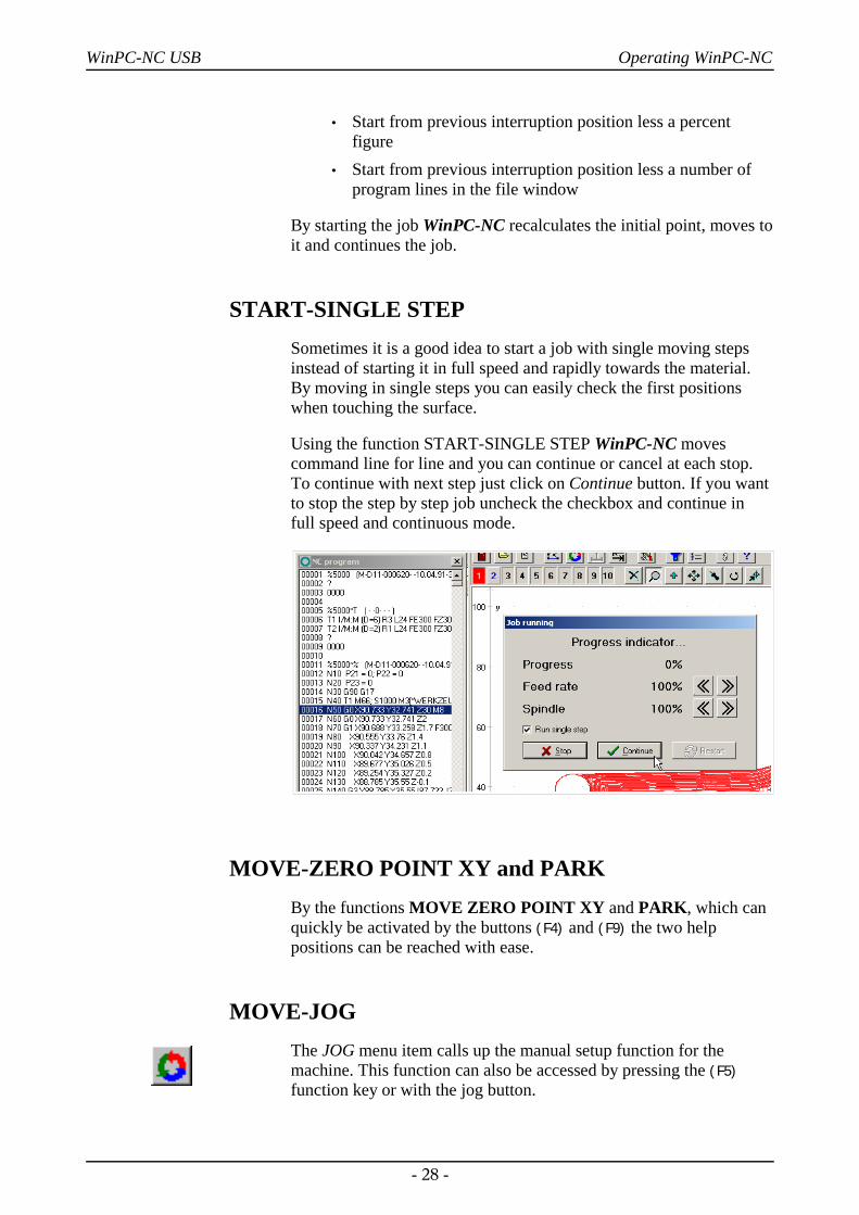
START-SINGLE STEPSometimes it is a good idea to start a job with single moving stepsinstead of starting it in full speed and rapidly towards the material.By moving in single steps you can easily check the first positionswhen touching the surface.
Using the function START-SINGLE STEP WinPC-NC movescommand line for line and you can continue or cancel at each stop.To continue with next step just click on Continue button. If you wantto stop the step by step job uncheck the checkbox and continue infull speed and continuous mode.
MOVE-ZERO POINT XY and PARKBy the functions MOVE ZERO POINT XY and PARK, which canquickly be activated by the buttons (F4) and (F9) the two helppositions can be reached with ease.
MOVE-JOGThe JOG menu item calls up the manual setup function for themachine. This function can also be accessed by pressing the (F5)function key or with the jog button.
- 28 -
WinPC-NC USB Operating WinPC-NC
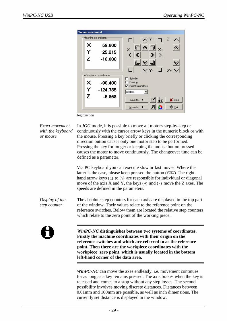
Jog function
Exact movementwith the keyboardor mouse
In JOG mode, it is possible to move all motors step-by-step orcontinuously with the cursor arrow keys in the numeric block or withthe mouse. Pressing a key briefly or clicking the correspondingdirection button causes only one motor step to be performed.Pressing the key for longer or keeping the mouse button pressedcauses the motor to move continuously. The changeover time can bedefined as a parameter.
Via PC keyboard you can execute slow or fast moves. Where thelatter is the case, please keep pressed the button (STRG).The right-hand arrow keys (1) to (9) are responsible for individual or diagonalmove of the axis X and Y, the keys (+) and (-) move the Z axes. Thespeeds are defined in the parameters.
Display of the step counter
The absolute step counters for each axis are displayed in the top partof the window. Their values relate to the reference point on thereference switches. Below them are located the relative step counterswhich relate to the zero point of the working piece.
i WinPC-NC distinguishes between two systems of coordinates.Firstly the machine coordinates with their origin on thereference switches and which are referred to as the referencepoint. Then there are the workpiece coordinates with theworkpiece zero point, which is usually located in the bottomleft-hand corner of the data area.
WinPC-NC can move the axes endlessly, i.e. movement continuesfor as long as a key remains pressed. The axis brakes when the key isreleased and comes to a stop without any step losses. The secondpossibility involves moving discrete distances. Distances between0.01mm and 100mm are possible, as well as inch dimensions. Thecurrently set distance is displayed in the window.
- 29 -
WinPC-NC USB Operating WinPC-NC
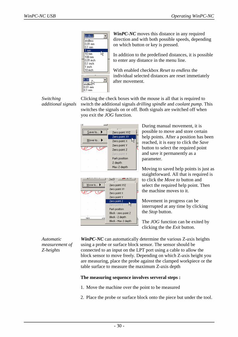
WinPC-NC moves this distance in any requireddirection and with both possible speeds, dependingon which button or key is pressed.
In addition to the predefined distances, it is possibleto enter any distance in the menu line.
With enabled checkbox Reset to endless theindividual selected distances are reset immetiatelyafter movement.
Switchingadditional signals
Clicking the check boxes with the mouse is all that is required toswitch the additional signals drilling spindle and coolant pump. Thisswitches the signals on or off. Both signals are switched off whenyou exit the JOG function.
During manual movement, it ispossible to move and store certainhelp points. After a position has beenreached, it is easy to click the Savebutton to select the required pointand save it permanently as a parameter.
Moving to saved help points is just asstaightforward. All that is required isto click the Move to button and select the required help point. Thenthe machine moves to it.
Movement in progress can beinterrupted at any time by clickingthe Stop button.
The JOG function can be exited byclicking the the Exit button.
Automaticmeasurement of Z-heights
WinPC-NC can automatically determine the various Z-axis heightsusing a probe or surface block sensor. The sensor should beconnected to an input on the LPT port using a cable to allow theblock sensor to move freely. Depending on which Z-axis height youare measuring, place the probe against the clamped workpiece or thetable surface to measure the maximum Z-axis depth
The measuring sequence involves serveral steps :
1. Move the machine over the point to be measured
2. Place the probe or surface block onto the piece but under the tool.
- 30 -
WinPC-NC USB Operating WinPC-NC
3. Start the measurement. WinPC-NC moves the Z axis downwardsslowly until the probe contact trips. Then the axis stops andWinPC-NC transfers the measured value and the probe width asparameters. The probe width can be defined as a parameter.
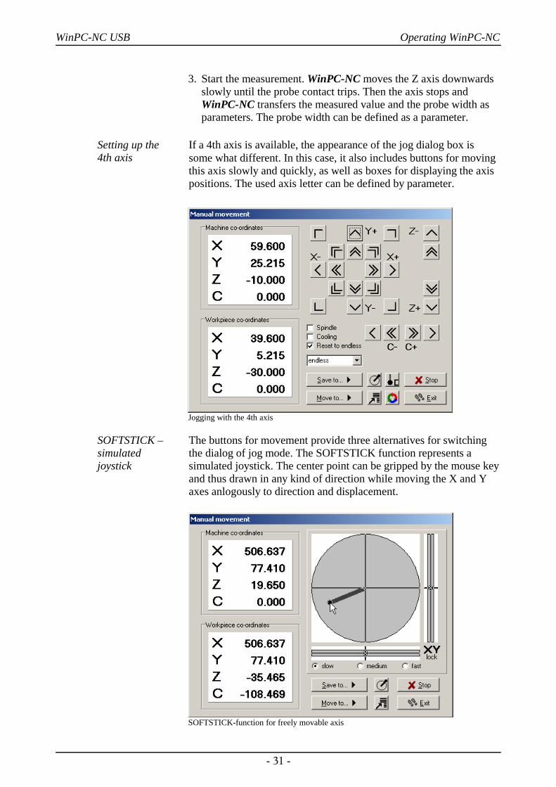
Setting up the 4th axis
If a 4th axis is available, the appearance of the jog dialog box issome what different. In this case, it also includes buttons for movingthis axis slowly and quickly, as well as boxes for displaying the axispositions. The used axis letter can be defined by parameter.
Jogging with the 4th axis
SOFTSTICK – simulated joystick
The buttons for movement provide three alternatives for switchingthe dialog of jog mode. The SOFTSTICK function represents asimulated joystick. The center point can be gripped by the mouse keyand thus drawn in any kind of direction while moving the X and Yaxes anlogously to direction and displacement.
SOFTSTICK-function for freely movable axis
- 31 -
WinPC-NC USB Operating WinPC-NC
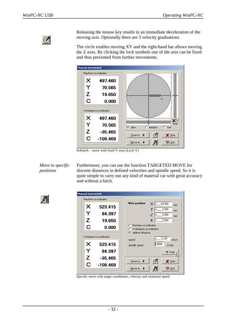
Releasing the mouse key results in an immediate deceleration of themoving axis. Optionally there are 3 velocity graduations.
The circle enables moving XY and the right-hand bar allows movingthe Z axes. By clicking the lock symbols one of the axis can be fixedand thus prevented from further movements.
Softstick – move with fixed Y-axes (Lock-Y)
Move to specificpositions
Furthermore, you can use the function TARGETED MOVE fordiscrete distances in defined velocities and spindle speed. So it isquite simple to carry out any kind of material cut with great accuracyand without a hitch.
Specific move with target coordinates, velocity and rotational speed
- 32 -
WinPC-NC USB Operating WinPC-NC
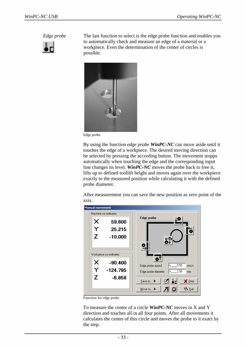
Edge probe The last function to select is the edge probe function and enables youto automatically check and measure an edge of a material or aworkpiece. Even the determination of the center of circles ispossible.
Edge probe
By using the function edge probe WinPC-NC can move aside until ittouches the edge of a workpiece. The desired moving direction canbe selected by pressing the according button. The movement stoppsautomatically when touching the edge and the corresponding inputline changes its level. WinPC-NC moves the probe back to free it,lifts up to defined toollift height and moves again over the workpieceexactly to the measured position while calculating it with the definedprobe diameter.
After measurement you can save the new position as zero point of theaxis.
Function for edge probe
To measure the center of a circle WinPC-NC moves in X and Ydirection and touches all in all four points. After all movements itcalculates the center of this circle and moves the probe to it exact bythe step.
- 33 -
WinPC-NC USB Operating WinPC-NC
MOVE-JOYSTICK JOGGINGAs an alternative to the mouse and keyboard, it is also possible tomove the machine manually using a connected joystick. This is ofadvantage for observing the movements directly on the machine andsetting exact positions. It is easier to take a joystick to the machinethan keyboard or mouse.
i Prior to use a connected joystick it must be configured in theWindows system and calibrated with a special function.
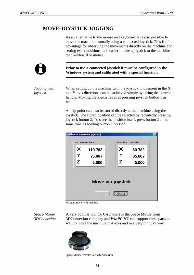
Jogging withjoystick
When setting up the machine with the joystick, movement in the Xand Y-axis directions can be achieved simply by tilting the controlhandle. Moving the Z-axis requires pressing joystick button 1 aswell.
A help point can also be stored directly at the machine using thejoystick. The stored position can be selected by repeatedly pressingjoystick button 2. To store the position itself, press button 2 at thesame time as holding button 1 pressed.
Manual move with joystick
Space-Mouse3DConnexion
A very popular tool for CAD users is the Space Mouse from3DConnexion company and WinPC-NC can support these parts aswell to move the machine in 4 axes and in a very intuitive way.
Space Mouse Wireless of 3DConnexion
- 34 -
WinPC-NC USB Operating WinPC-NC
When using a Space Mouse you first have to define the type ofconnection under parameters-interface and of course thecorresponding drivers must be installed in your Windows system.
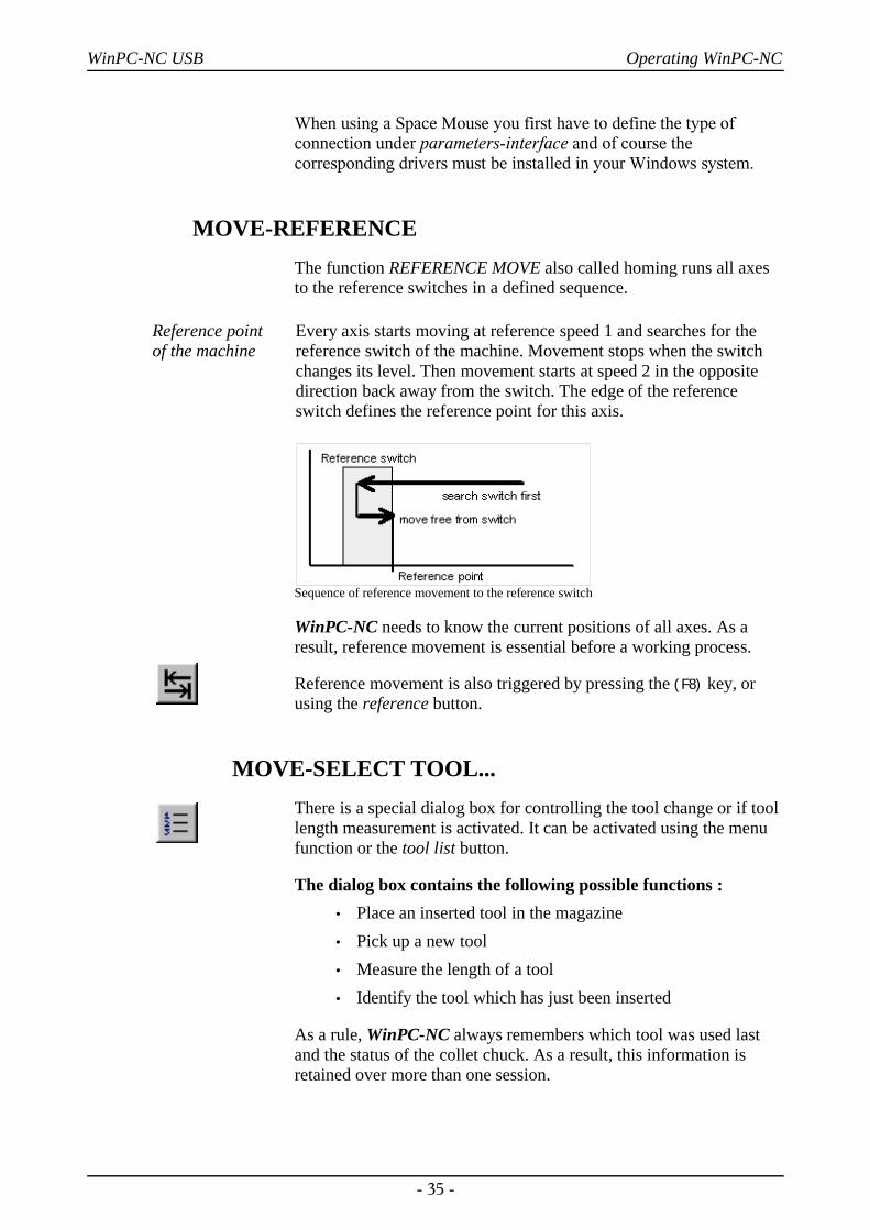
MOVE-REFERENCEThe function REFERENCE MOVE also called homing runs all axesto the reference switches in a defined sequence.
Reference point of the machine
Every axis starts moving at reference speed 1 and searches for thereference switch of the machine. Movement stops when the switchchanges its level. Then movement starts at speed 2 in the oppositedirection back away from the switch. The edge of the referenceswitch defines the reference point for this axis.
Sequence of reference movement to the reference switch
WinPC-NC needs to know the current positions of all axes. As aresult, reference movement is essential before a working process.
Reference movement is also triggered by pressing the (F8) key, orusing the reference button.
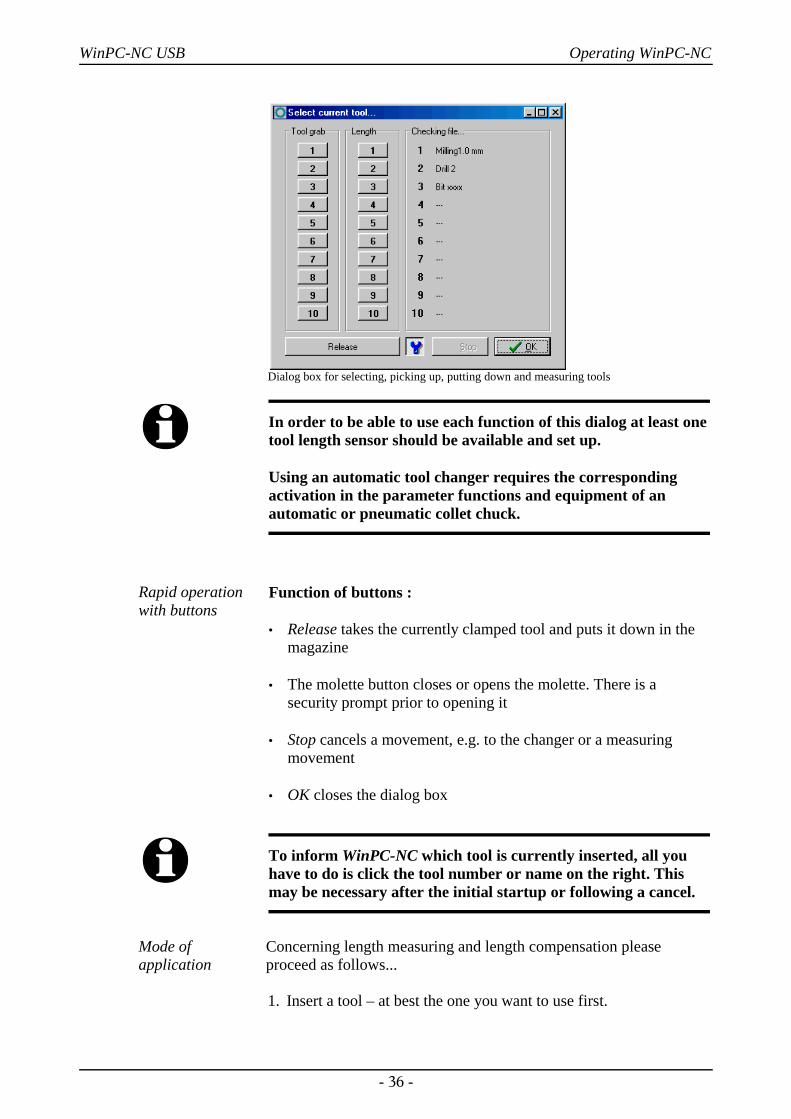
MOVE-SELECT TOOL...There is a special dialog box for controlling the tool change or if toollength measurement is activated. It can be activated using the menufunction or the tool list button.
The dialog box contains the following possible functions :• Place an inserted tool in the magazine• Pick up a new tool• Measure the length of a tool• Identify the tool which has just been inserted
As a rule, WinPC-NC always remembers which tool was used lastand the status of the collet chuck. As a result, this information isretained over more than one session.
- 35 -
WinPC-NC USB Operating WinPC-NC
Dialog box for selecting, picking up, putting down and measuring tools
i In order to be able to use each function of this dialog at least onetool length sensor should be available and set up.
Using an automatic tool changer requires the correspondingactivation in the parameter functions and equipment of anautomatic or pneumatic collet chuck.
Rapid operationwith buttons
Function of buttons :
• Release takes the currently clamped tool and puts it down in themagazine
• The molette button closes or opens the molette. There is asecurity prompt prior to opening it
• Stop cancels a movement, e.g. to the changer or a measuringmovement
• OK closes the dialog box
i To inform WinPC-NC which tool is currently inserted, all youhave to do is click the tool number or name on the right. Thismay be necessary after the initial startup or following a cancel.
Mode ofapplication
Concerning length measuring and length compensation pleaseproceed as follows...
1. Insert a tool – at best the one you want to use first.
- 36 -
WinPC-NC USB Operating WinPC-NC
2. Information to WinPC-NC concerning the current active tool viathe tool change dialog and ensuing manual measurement. For thisplease simply click the measurement button for the correspondingtool. The new tool number is immediately displayed in the statusbar and WinPC-NC moves the tool to the length sensor forautomatic length measuring. The information concerning whichtool is used as reference tool and the corresponding length is nowavailable.
3. The next step is loading the job and defining the zero point byinserted tool, especially defining the Z zero point.This can beeffected as usual, e. g. by scratching the surface.
4. Finally please start the job. WinPC-NC asks for a change witheach new tool and then meaures the tool length automatically. Theexact length differences to the reference tool are calculated andrespected with subsequent tools concerning the Z height.
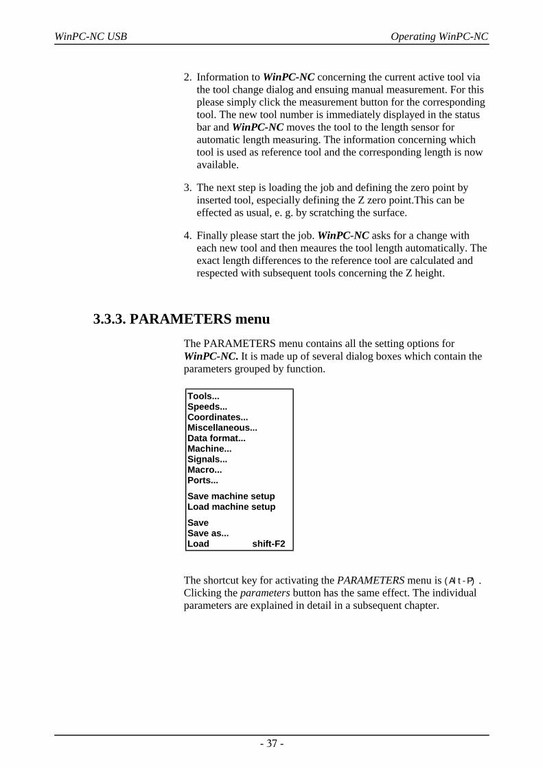
3.3.3. PARAMETERS menuThe PARAMETERS menu contains all the setting options forWinPC-NC. It is made up of several dialog boxes which contain theparameters grouped by function.
The shortcut key for activating the PARAMETERS menu is (Alt-P) .Clicking the parameters button has the same effect. The individualparameters are explained in detail in a subsequent chapter.
- 37 -
Tools...Speeds...Coordinates...Miscellaneous...Data format...Machine...Signals...Macro...Ports...
Save machine setupLoad machine setup
SaveSave as...Load shift-F2
WinPC-NC USB Operating WinPC-NC
PARAMETER-SAVE/LOAD MACHINE SETUP
Save and loadcomplete profiles
WinPC-NC offers a function to save and reload complete profilesettings for different applications like milling, tangentional cutting or3D printing. The saved setup file includes all parameter settings ofWinPC-NC itself and of the machine as well as defined macros andmore settings.
All applications can easily be reloaded after setting up your machinefor the new task.
Files containing the machine setup data are named by the project and*.WMS as extension.
PARAMETER-SAVE
Saving parametersspecifically for aproject
All parameter and tool settings can be stored in files using the SAVEmenu item. It is possible to save the settings for a working file or fora project.
The SAVE function operates as follows : When a working file isloaded, WinPC-NC stores all workpiece-related settings such as thezero point, scaling, etc. in a parameter and tool file associated withthe working file. The files have the same name as the working file,with the endings*.WPI and *.WPW, z.B. HOLDER.WPI orENGRAVING.WPW.
Whenever these working files are loaded in the future, all the settingsand tools are once again available without having to be redefined.
The machine-related parameters such as axis resolution, referencedirections or the interfaces used are always stored in the standardparameter file WINPCNC.WPI.
If no working file is selected when you save, the Save function storesall settings in the default files WINPCNC.WPI andWINPCNC.WPW.
- 38 -
WinPC-NC USB Operating WinPC-NC
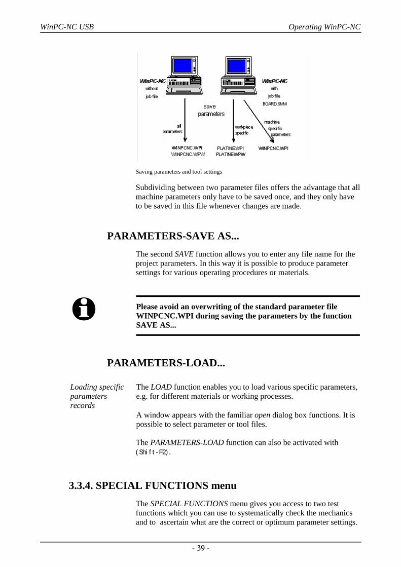
Saving parameters and tool settings
Subdividing between two parameter files offers the advantage that allmachine parameters only have to be saved once, and they only haveto be saved in this file whenever changes are made.
PARAMETERS-SAVE AS...The second SAVE function allows you to enter any file name for theproject parameters. In this way it is possible to produce parametersettings for various operating procedures or materials.
i Please avoid an overwriting of the standard parameter fileWINPCNC.WPI during saving the parameters by the functionSAVE AS...
PARAMETERS-LOAD...
Loading specificparametersrecords
The LOAD function enables you to load various specific parameters,e.g. for different materials or working processes.
A window appears with the familiar open dialog box functions. It ispossible to select parameter or tool files.
The PARAMETERS-LOAD function can also be activated with(Shift-F2).
3.3.4. SPECIAL FUNCTIONS menuThe SPECIAL FUNCTIONS menu gives you access to two testfunctions which you can use to systematically check the mechanicsand to ascertain what are the correct or optimum parameter settings.
- 39 -
WinPC-NC USB Operating WinPC-NC
Also, a joystick calibration function and a position check function areintegrated here.
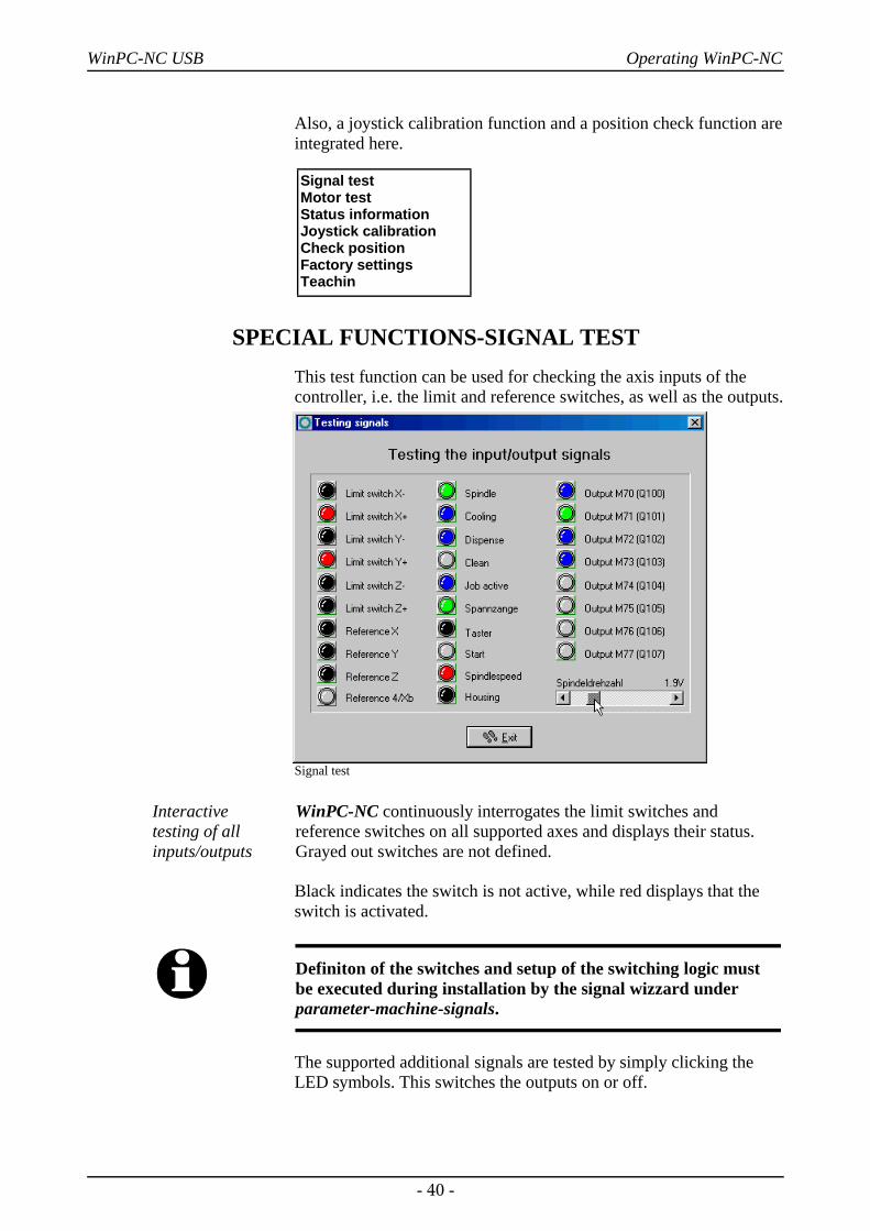
SPECIAL FUNCTIONS-SIGNAL TESTThis test function can be used for checking the axis inputs of thecontroller, i.e. the limit and reference switches, as well as the outputs.
Signal test
Interactive testing of allinputs/outputs
WinPC-NC continuously interrogates the limit switches andreference switches on all supported axes and displays their status.Grayed out switches are not defined.
Black indicates the switch is not active, while red displays that theswitch is activated.
i Definiton of the switches and setup of the switching logic mustbe executed during installation by the signal wizzard underparameter-machine-signals.
The supported additional signals are tested by simply clicking theLED symbols. This switches the outputs on or off.
- 40 -
Signal testMotor testStatus informationJoystick calibrationCheck positionFactory settingsTeachin
WinPC-NC USB Operating WinPC-NC
Testing the spindle speed
There is a slider in the bottom right-hand corner of the window. Thissets the analog output for checking the spindle speed. It can beinfinitely varied between 0V and 10V and outputs this value binarycoded at LPT2 port of ncUSB or as an PWM signal.
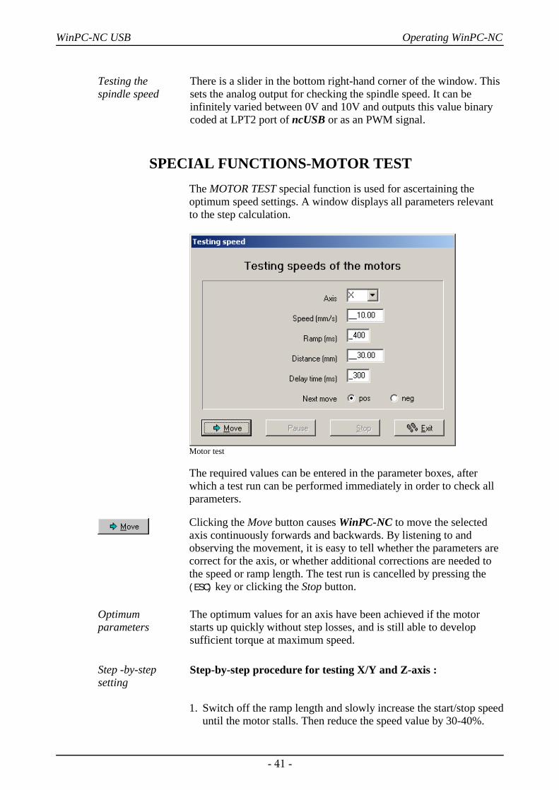
SPECIAL FUNCTIONS-MOTOR TESTThe MOTOR TEST special function is used for ascertaining theoptimum speed settings. A window displays all parameters relevantto the step calculation.
Motor test
The required values can be entered in the parameter boxes, afterwhich a test run can be performed immediately in order to check allparameters.
Clicking the Move button causes WinPC-NC to move the selectedaxis continuously forwards and backwards. By listening to andobserving the movement, it is easy to tell whether the parameters arecorrect for the axis, or whether additional corrections are needed tothe speed or ramp length. The test run is cancelled by pressing the(ESC) key or clicking the Stop button.
Optimumparameters
The optimum values for an axis have been achieved if the motorstarts up quickly without step losses, and is still able to developsufficient torque at maximum speed.
Step -by-stepsetting
Step-by-step procedure for testing X/Y and Z-axis :
1. Switch off the ramp length and slowly increase the start/stop speeduntil the motor stalls. Then reduce the speed value by 30-40%.
- 41 -
WinPC-NC USB Operating WinPC-NC
2. Test the ramp length with various values. You have achieved agood value if the motor starts up quickly without stalling.
3. Increase the rapid speed in stages. The motor should run quicklywhile still developing sufficient torque.
Having ascertained the values, you can store them as parameters forthe axis in question. All parameters and their functions are explainedin a subsequent chapter.
i The optimum parameters for a stepper motor axis depend onmany factors, e.g. the motor characteristic, the type of drive used(spindle or belt) and the load to be moved.
It is absolutely impossible to draw any conclusions from theascertained values for one axes regarding the max. speed of thetotal plant system or regarding the possibly reachable speedsduring the job performance.
SPECIAL FUNCTIONS-STATUS INFORMATION
Informationen about the communicationmodule
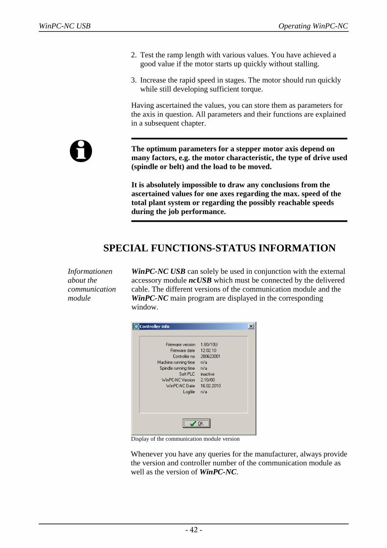
WinPC-NC USB can solely be used in conjunction with the externalaccessory module ncUSB which must be connected by the deliveredcable. The different versions of the communication module and theWinPC-NC main program are displayed in the correspondingwindow.
Display of the communication module version
Whenever you have any queries for the manufacturer, always providethe version and controller number of the communication module aswell as the version of WinPC-NC.
- 42 -
WinPC-NC USB Operating WinPC-NC
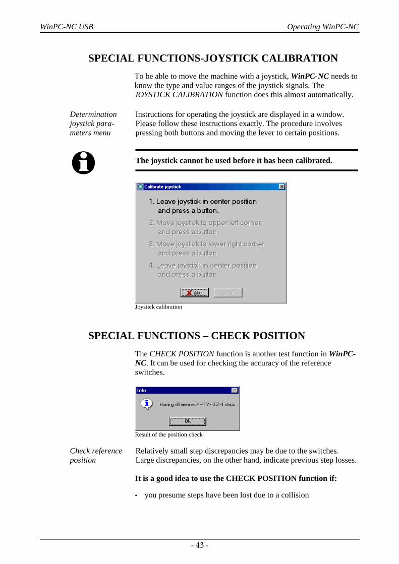
SPECIAL FUNCTIONS-JOYSTICK CALIBRATIONTo be able to move the machine with a joystick, WinPC-NC needs toknow the type and value ranges of the joystick signals. TheJOYSTICK CALIBRATION function does this almost automatically.
Determinationjoystick para-meters menu
Instructions for operating the joystick are displayed in a window.Please follow these instructions exactly. The procedure involvespressing both buttons and moving the lever to certain positions.
i The joystick cannot be used before it has been calibrated.
Joystick calibration
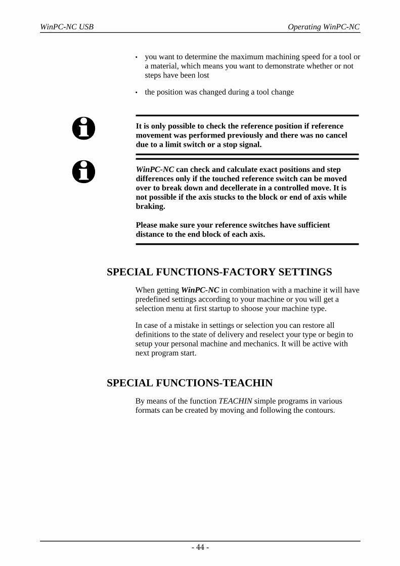
SPECIAL FUNCTIONS – CHECK POSITIONThe CHECK POSITION function is another test function in WinPC-NC. It can be used for checking the accuracy of the referenceswitches.
Result of the position check
Check referenceposition
Relatively small step discrepancies may be due to the switches.Large discrepancies, on the other hand, indicate previous step losses.
It is a good idea to use the CHECK POSITION function if:
• you presume steps have been lost due to a collision
- 43 -
WinPC-NC USB Operating WinPC-NC
• you want to determine the maximum machining speed for a tool ora material, which means you want to demonstrate whether or notsteps have been lost
• the position was changed during a tool change
i It is only possible to check the reference position if referencemovement was performed previously and there was no canceldue to a limit switch or a stop signal.
i WinPC-NC can check and calculate exact positions and stepdifferences only if the touched reference switch can be movedover to break down and decellerate in a controlled move. It isnot possible if the axis stucks to the block or end of axis whilebraking.
Please make sure your reference switches have sufficientdistance to the end block of each axis.
SPECIAL FUNCTIONS-FACTORY SETTINGSWhen getting WinPC-NC in combination with a machine it will havepredefined settings according to your machine or you will get aselection menu at first startup to shoose your machine type.
In case of a mistake in settings or selection you can restore alldefinitions to the state of delivery and reselect your type or begin tosetup your personal machine and mechanics. It will be active withnext program start.
SPECIAL FUNCTIONS-TEACHINBy means of the function TEACHIN simple programs in variousformats can be created by moving and following the contours.
- 44 -
WinPC-NC USB Operating WinPC-NC
Special function teachin
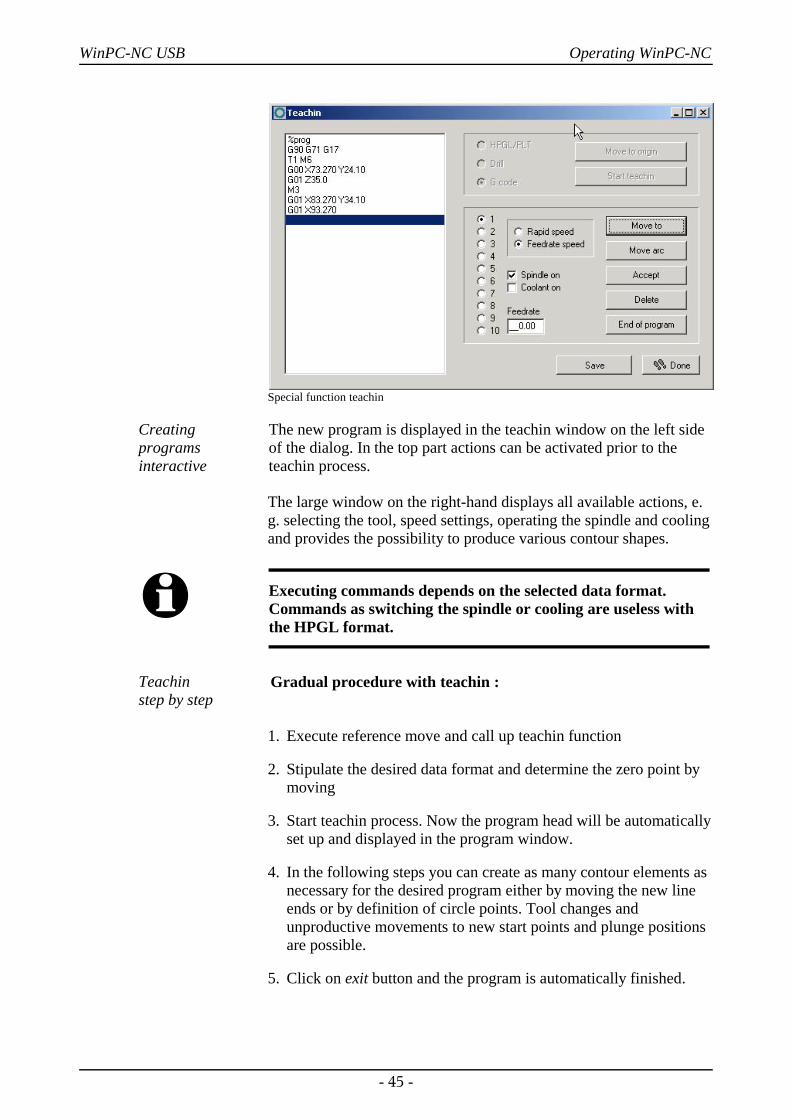
Creating programsinteractive
The new program is displayed in the teachin window on the left sideof the dialog. In the top part actions can be activated prior to theteachin process.
The large window on the right-hand displays all available actions, e.g. selecting the tool, speed settings, operating the spindle and coolingand provides the possibility to produce various contour shapes.
i Executing commands depends on the selected data format.Commands as switching the spindle or cooling are useless withthe HPGL format.
Teachin step by step
Gradual procedure with teachin :
1. Execute reference move and call up teachin function
2. Stipulate the desired data format and determine the zero point bymoving
3. Start teachin process. Now the program head will be automaticallyset up and displayed in the program window.
4. In the following steps you can create as many contour elements asnecessary for the desired program either by moving the new lineends or by definition of circle points. Tool changes andunproductive movements to new start points and plunge positionsare possible.
5. Click on exit button and the program is automatically finished.
- 45 -
WinPC-NC USB Operating WinPC-NC
6. The new created program should be stored before leaving thefunction.
Possible actions during the teachin process are as follows :
Move line Moving to a new position. This moving step is either an operation inopen curcuit with high speed or immersed with feed rate. Severallines can be teached successively and the function is left if no othermovement has taken place.
Circle arc Teachin of a circle or arc is taking place with always three points.The first point is also the current position. First any point on thecircle arc is being moved to and finally the final point. By these threepoints a circle or arc command can be cleary created.
Accept This function inserts the actual position of to the cursor bar into theprogram.
Delete Deletes the line of the cursor bar. With this function it is alsopossible to delete and correct previous commands.
Exit Inserts the necessary commands for exiting the program and finishesthe new created NC program.
i New commands are always inserted at the actual cursor positionand enables the user to make up for overlooked actions.
3.3.5. HELP-menuThere are three items in the help menu:
HELP-TOPICSThe HELP TOPICS function gives you access to the help system. Adialog box appears containing the main selection.
- 46 -
Help topics...LiabilityAbout WinPC-NC
WinPC-NC USB Operating WinPC-NC
HELP-LIABILITYThe HELP-LIABILITY function displays a text with the licenseconditions and a disclaimer. Please read this information carefullybefore using WinPC-NC.
HELP-ABOUT WinPC-NCActivating this menu function displays information about the currentversion and revision number.
Information about the current version
- 47 -
WinPC-NC USB 2D-CAM functions
4. 2D-CAM functions
4.1. OverviewConcerning 2D data WinPC-NC provides special functions forsorting and preparing data for subsequent processing. Followingfunctions are selectable and adjustable in a separate input dialog area.
– Assigning tools according to use
– Cleaning up data, deleting zero vector and double lines
– Setting output sequence according to tool number
– Optimizing empty moves
– Tool diameter offset compensation in contours
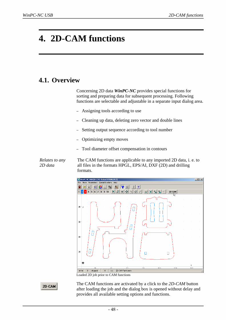
Relates to any 2D data
The CAM functions are applicable to any imported 2D data, i. e. toall files in the formats HPGL, EPS/AI, DXF (2D) and drillingformats.
Loaded 2D job prior to CAM functions
The CAM functions are activated by a click to the 2D-CAM buttonafter loading the job and the dialog box is opened without delay andprovides all available setting options and functions.
- 48 -
WinPC-NC USB 2D-CAM functions
4.2. Setting options
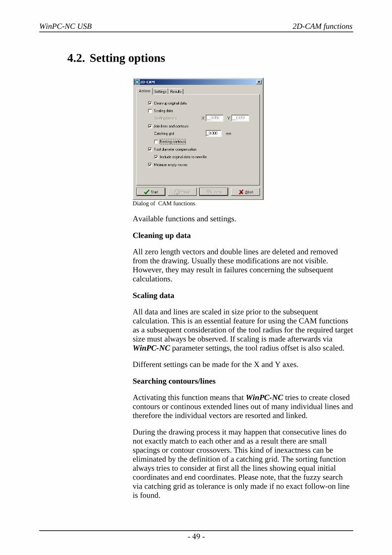
Dialog of CAM functions
Available functions and settings.
Cleaning up data
All zero length vectors and double lines are deleted and removedfrom the drawing. Usually these modifications are not visible.However, they may result in failures concerning the subsequentcalculations.
Scaling data
All data and lines are scaled in size prior to the subsequentcalculation. This is an essential feature for using the CAM functionsas a subsequent consideration of the tool radius for the required targetsize must always be observed. If scaling is made afterwards viaWinPC-NC parameter settings, the tool radius offset is also scaled.
Different settings can be made for the X and Y axes.
Searching contours/lines
Activating this function means that WinPC-NC tries to create closedcontours or continous extended lines out of many individual lines andtherefore the individual vectors are resorted and linked.
During the drawing process it may happen that consecutive lines donot exactly match to each other and as a result there are smallspacings or contour crossovers. This kind of inexactness can beeliminated by the definition of a catching grid. The sorting functionalways tries to consider at first all the lines showing equal initialcoordinates and end coordinates. Please note, that the fuzzy searchvia catching grid as tolerance is only made if no exact follow-on lineis found.
- 49 -
WinPC-NC USB 2D-CAM functions
By using an additional button the CAM function is induced to findand mark enclosed lines and contours, i. e. elements which arecompletely surrounded by other contours. This is an essential featurefor a radius correction later on.
Calculating tool diameter offsets
For compensating diameters or radii of used tools in path contours itis possible to compute a radius correction for closed contours andthus the actual paths can be offset by a special set distance to theinside or outside.
The radii values are set in the next dialog box. By using an additionalbutton it is possible to assume the grey-coloured original lines andtool numbers exceeding 100 for the new graphics data output. Thusthe visual control is simplified and former lines are not consideredwhile job processing.
Optimizing empty moves
Prior to the output of the calculated data in a new NC file, WinPC-NC tries to optimize or minimize the empty moves between lines andcontours. This saves processing time and helps to increase the plant‘sefficiency.
First of all the surrounded elements are considered and thereafter thecorresponding contours. Thus it can be avoided that workpieces aremachined that have previously already been completely milled.
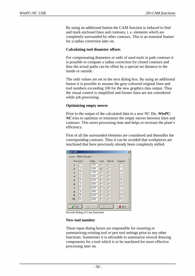
Second dialog of Cam functions
New tool number
These input dialog boxes are responsible for resorting orsummarizing existing tool or pen tool settings prior to any otherfunctions. Sometimes it is advisable to summarize several drawingcomponents for a tool which is to be machined for more effectiveprocessing later on.
- 50 -
WinPC-NC USB 2D-CAM functions
Radius
The radius of all the used tools is defined for the radiuscompensation. The path which is to be recalculated is accordinglyplaced with contours to the inside or outside.
Inside
This button determines the direction of the relocated new path. Theline offset is made to the inside if you have clicked to Inside,otherwise the line offset is made to the outside.
Climb milling
Travel direction of the milling tool along the contour is defined byclimb milling and up-cut milling.
Sequence of operation
Finally the tool sequence is determined for creating the new file. Allelements of this tool are always jointed and possibly an empty moveoptimization is carried out.
Newly created file is immediatelyloaded
After completion of all required calculations and resortings WinPC-NC creates a new 2D file in an intern used format and gives thepreceding name of the project and the ending *.OPT.
During the process or after intermediate steps it is possible to make areset to the original file and the original display and to executerepetitions with changed values and functions. For these proceduresthe buttons START, RESET, DONE and ABORT are applicable.
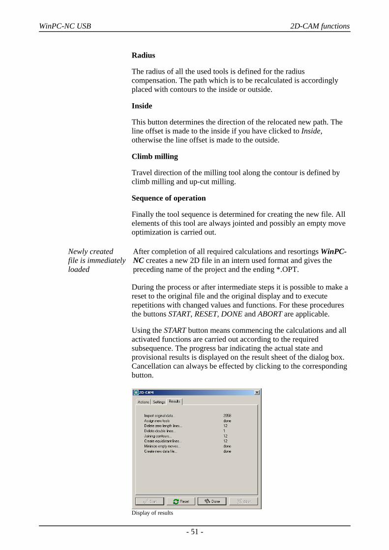
Using the START button means commencing the calculations and allactivated functions are carried out according to the requiredsubsequence. The progress bar indicating the actual state andprovisional results is displayed on the result sheet of the dialog box.Cancellation can always be effected by clicking to the correspondingbutton.
Display of results
- 51 -
WinPC-NC USB 2D-CAM functions
Having successfully calculated and generated the new file, thecontours are immediately visible in the graphics display and thecorresponding result can be checked. Subsequently it is possible tostart a recalculation with modified settings or activate EXIT foradopting the results by using the buttons RESET and DONE.
Functions asrequired and inany possiblecombination
Due to the activation of individual functions it is possible to use anykind of compilation and combination according to data file andrequirement.
For example concerning the drilling data of a board you have just tostart the empty move optimization. In order to achieve a bettersurface result with millings and engravings you have to clean up thedata and join contours or lines. Alternatively you just modify theprocessing sequence.
4.3. Example 1For an efficient use of the most important functions we provide adetailed and step-by-step description on the base of examples.
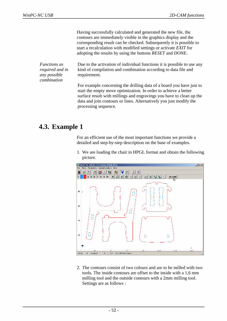
1. We are loading the chair in HPGL format and obtain the followingpicture.
2. The contours consist of two colours and are to be milled with twotools. The inside contours are offset to the inside with a 1,6 mmmilling tool and the outside contours with a 2mm milling tool.Settings are as follows :
- 52 -
WinPC-NC USB 2D-CAM functions
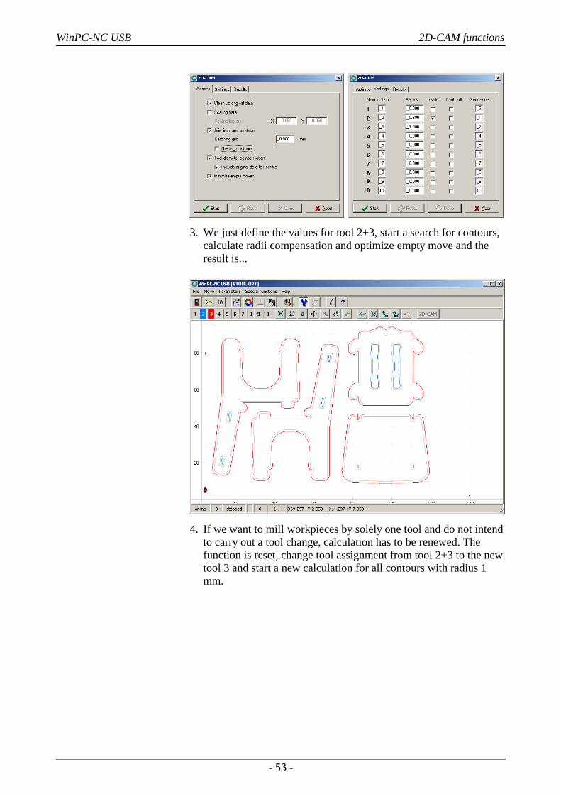
3. We just define the values for tool 2+3, start a search for contours,calculate radii compensation and optimize empty move and theresult is...
4. If we want to mill workpieces by solely one tool and do not intendto carry out a tool change, calculation has to be renewed. Thefunction is reset, change tool assignment from tool 2+3 to the newtool 3 and start a new calculation for all contours with radius 1mm.
- 53 -
WinPC-NC USB 2D-CAM functions
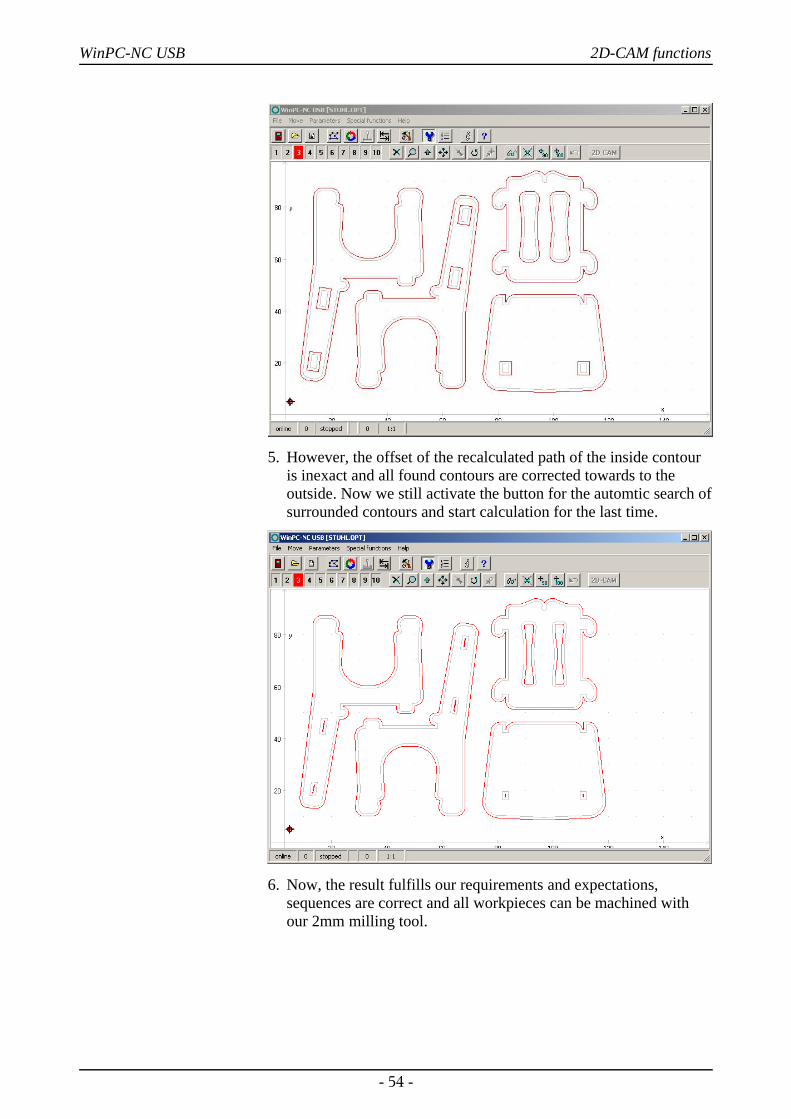
5. However, the offset of the recalculated path of the inside contouris inexact and all found contours are corrected towards to theoutside. Now we still activate the button for the automtic search ofsurrounded contours and start calculation for the last time.
6. Now, the result fulfills our requirements and expectations,sequences are correct and all workpieces can be machined withour 2mm milling tool.
- 54 -
WinPC-NC USB 2D-CAM functions
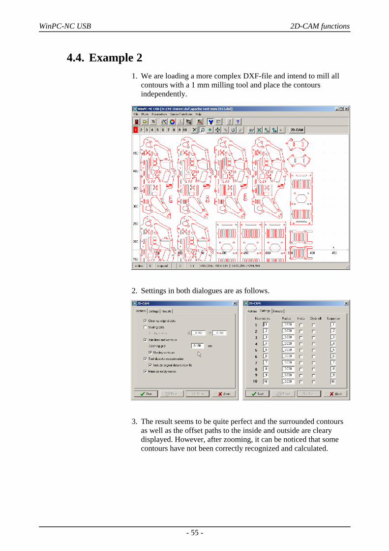
4.4. Example 21. We are loading a more complex DXF-file and intend to mill all
contours with a 1 mm milling tool and place the contoursindependently.
2. Settings in both dialogues are as follows.
3. The result seems to be quite perfect and the surrounded contoursas well as the offset paths to the inside and outside are clearydisplayed. However, after zooming, it can be noticed that somecontours have not been correctly recognized and calculated.
- 55 -
WinPC-NC USB 2D-CAM functions
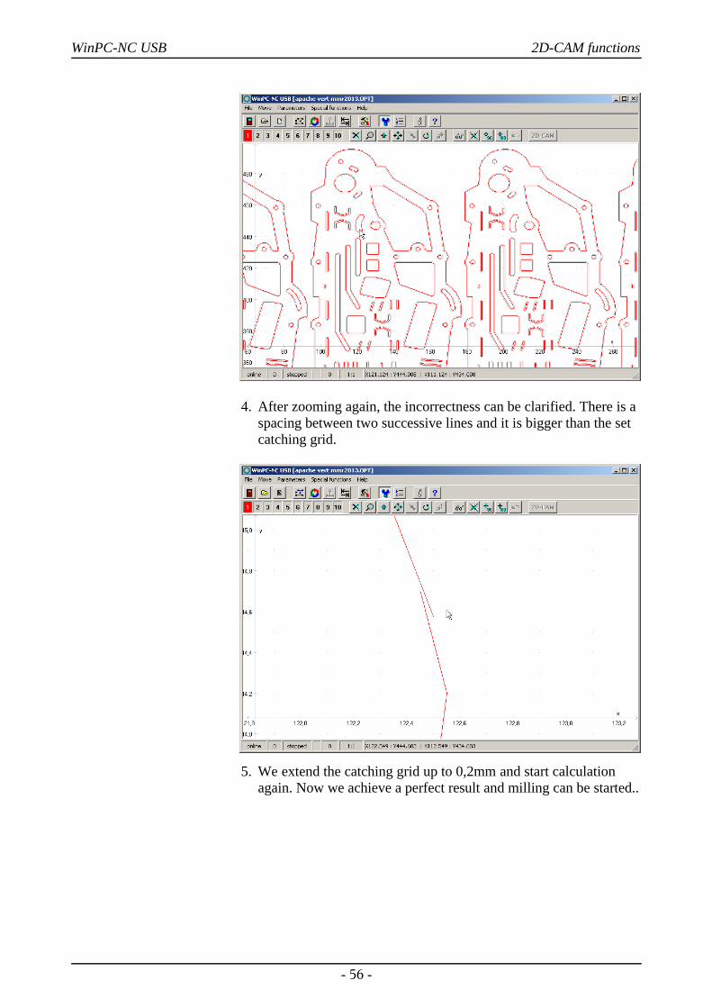
4. After zooming again, the incorrectness can be clarified. There is aspacing between two successive lines and it is bigger than the setcatching grid.
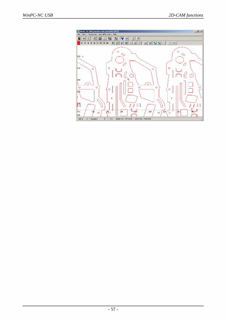
5. We extend the catching grid up to 0,2mm and start calculationagain. Now we achieve a perfect result and milling can be started..
- 56 -
WinPC-NC USB 2D-CAM functions
- 57 -
WinPC-NC USB Parameter settings
5. Parameter settings
5.1. Tool management
Project-relatedtool management
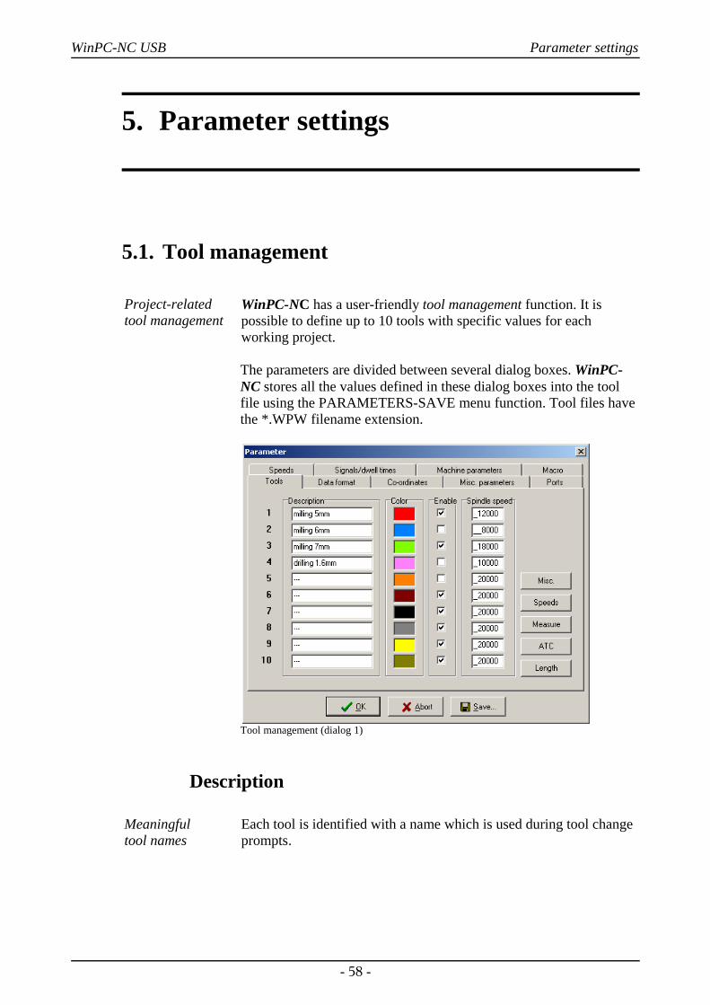
WinPC-NC has a user-friendly tool management function. It ispossible to define up to 10 tools with specific values for eachworking project.
The parameters are divided between several dialog boxes. WinPC-NC stores all the values defined in these dialog boxes into the toolfile using the PARAMETERS-SAVE menu function. Tool files havethe *.WPW filename extension.
Tool management (dialog 1)
Description
Meaningful tool names
Each tool is identified with a name which is used during tool changeprompts.
- 58 -
WinPC-NC USB Parameter settings
Color
Colors in thegraphical display
The Color parameter for each tool is used in the graphical display ofthe data. As a result, it is easy to adapt the color display to suit yourown requirements or to harmonize with the CAD program you areusing.
Clicking the colored box opens a dialog box in which you can selecta new color. All colors supported by the current Windows displaysettings can be selected.
Activation
Activating toolsindividually
Each tool can be individually enabled or blocked. Inactive tools aresimply ignored in the graphical display and the commands for themare skipped.
Spindle speedIt is possible to assign a spindle speed to each tool. This is set using adefined analog output when the tool is used.
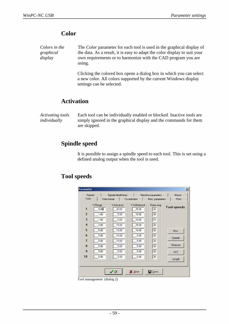
Tool speeds
Tool management (dialog 2)
- 59 -
WinPC-NC USB Parameter settings
Plunge speedThe plunge speed specifies the speed with which each tool is pushedinto the workpiece. It is necessary to consider certain limit valueshere, depending on the material and the tool.
Advance speedThe advance speed or feed rate defines the working speed for eachtool when the tool is pushed into the workpiece.
This value is irrelevant for straightforward drilling applications.However, if WinPC-NC is used for milling, engraving or grinding,then the maximum feed rate depends on the tool used and thematerial.
Withdrawal speedThe withdrawal speed is used for raising or withdrawing the toolfrom the workpiece.
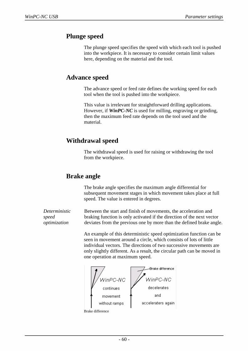
Brake angleThe brake angle specifies the maximum angle differential forsubsequent movement stages in which movement takes place at fullspeed. The value is entered in degrees.
Deterministicspeed optimization
Between the start and finish of movements, the acceleration andbraking function is only activated if the direction of the next vectordeviates from the previous one by more than the defined brake angle.
An example of this deterministic speed optimization function can beseen in movement around a circle, which consists of lots of littleindividual vectors. The directions of two successive movements areonly slightly different. As a result, the circular path can be moved inone operation at maximum speed.
Brake difference
- 60 -
WinPC-NC USB Parameter settings
Braking and acceleration always take place before and after toolmovements. This parameter is irrelevant in straightforward drillingapplications and is ignored.
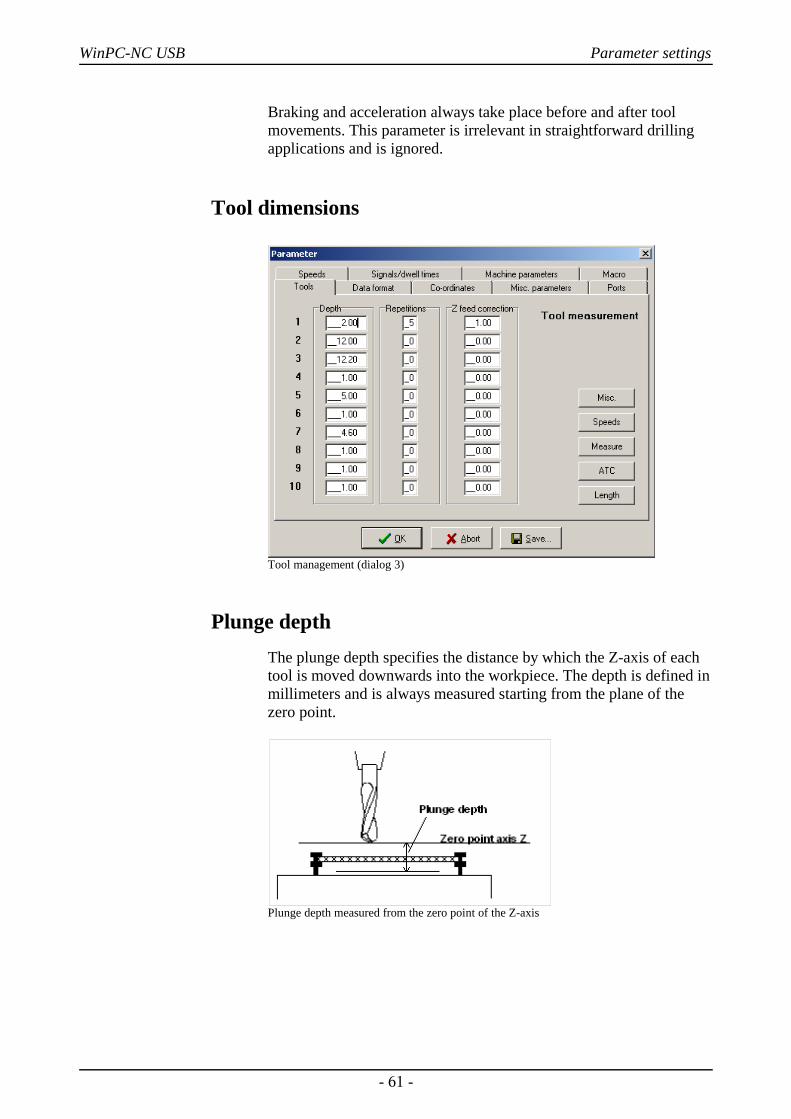
Tool dimensions
Tool management (dialog 3)
Plunge depthThe plunge depth specifies the distance by which the Z-axis of eachtool is moved downwards into the workpiece. The depth is defined inmillimeters and is always measured starting from the plane of thezero point.
Plunge depth measured from the zero point of the Z-axis
- 61 -
WinPC-NC USB Parameter settings
Repetitions
Routing in stages
Frequently, several passes are required when routing thick or hardmaterials. The parameters Repetitions and Z feed correction meanyou do not have to restart a working process several times insuccession using different plunge depths.
The repetition always applies to a complete contour line or for a hole,i.e. WinPC-NC remembers every insertion point and returns to itafter the tool is next withdrawn, in order to start the next pass.
Z-axis feed correctionDuring a series of repetitions, the Z-axis feed correction causes the Z-axis to be moved downwards by the specified value.
Repetitions and feed correction
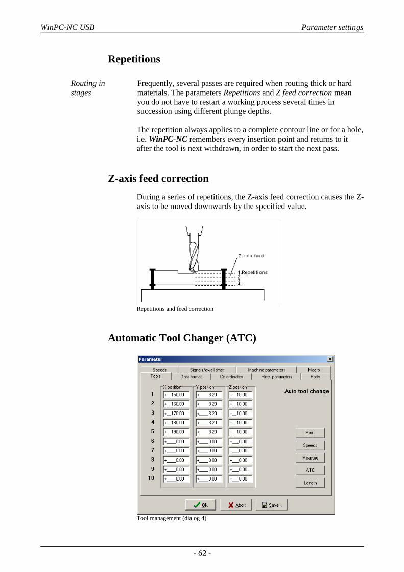
Automatic Tool Changer (ATC)
Tool management (dialog 4)
- 62 -
WinPC-NC USB Parameter settings
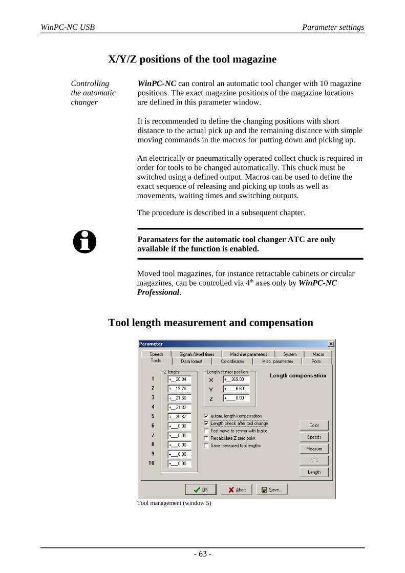
X/Y/Z positions of the tool magazine
Controlling the automaticchanger
WinPC-NC can control an automatic tool changer with 10 magazinepositions. The exact magazine positions of the magazine locationsare defined in this parameter window.
It is recommended to define the changing positions with shortdistance to the actual pick up and the remaining distance with simplemoving commands in the macros for putting down and picking up.
An electrically or pneumatically operated collect chuck is required inorder for tools to be changed automatically. This chuck must beswitched using a defined output. Macros can be used to define theexact sequence of releasing and picking up tools as well asmovements, waiting times and switching outputs.
The procedure is described in a subsequent chapter.
i Paramaters for the automatic tool changer ATC are onlyavailable if the function is enabled.
Moved tool magazines, for instance retractable cabinets or circularmagazines, can be controlled via 4th axes only by WinPC-NCProfessional.
Tool length measurement and compensation
Tool management (window 5)
- 63 -
WinPC-NC USB Parameter settings
Compensation of various toollengths
Working with different tools it usually does not happen that all toolsare of the same length. Therefore it is considerably difficult todetermine and observe the exact plunge depth.
WinPC-NC is able to measure the various lengths of toolsautomatically and compensate them during operation.
i Parameters for tool length measurement are only available if thefunction is enabled.
Z-axis lengthThe lengths of the tools used are defined here. Normally, the boxescannot be edited, however, the values are registered automaticallywhen the tools are measured. The length difference used by thecompensation function is calculated on the basis of these parametervalues.
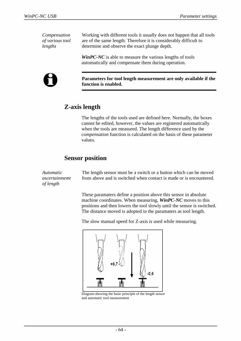
Sensor position
Automaticascertainmemt of length
The length sensor must be a switch or a button which can be movedfrom above and is switched when contact is made or is encountered.
These paramaters define a position above this sensor in absolutemachine coordinates. When measuring, WinPC-NC moves to thispositions and then lowers the tool slowly until the sensor is switched.The distance moved is adopted in the paramaters as tool length.
The slow manual speed for Z-axis is used while measuring.
Diagram showing the basic principle of the length sensor and automatic tool measurement
- 64 -
WinPC-NC USB Parameter settings
Automatic length correctionThis parameter activates automatic tool length compensation. Havinga separate parameter to enable this function makes it possible torestrict compensation to projects in which it is really needed.
i Tools are not automatically measured after being changed.Instead, this measurement must be explicitly selected using theMEASURE TOOL function before each tool is used.
Length check after tool changedThis parameter enables WinPC-NC to perform a tool length checkafter each tool change.
Fast move to sensor with brakeTo speed up the process you can activate the two step measurementand force WinPC-NC to move to the sensor with fast manual speed,brake the movement, reject the tool over the sensor and do themeasurement in a second step precisely.
Recalculate Z zero pointThe current Z zero point, e. g. positioned directly up on the materialsurface, is recalculated subsequent to each measurement. Thus it isno problem using identical tool numbers with tools of differentlengths.
After measuring a new tool and moving to the Z zero point by jogmove, it can immediately be realized that also the top of the new toolis exactly positioned at the defined Z zero point.
Save meassured tool lengthsIndicates WinPC-NC to save all current and meassured lengths intoparameter file so they can be used at next session withoutremeasurement.
- 65 -
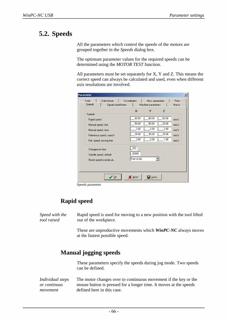
WinPC-NC USB Parameter settings
5.2. SpeedsAll the parameters which control the speeds of the motors aregrouped together in the Speeds dialog box.
The optimum parameter values for the required speeds can bedetermined using the MOTOR TEST function.
All parameters must be set separately for X, Y and Z. This means thecorrect speed can always be calculated and used, even when differentaxis resolutions are involved.
Speeds parameter
Rapid speed
Speed with the tool raised
Rapid speed is used for moving to a new position with the tool liftedout of the workpiece.
These are unproductive movements which WinPC-NC always movesat the fastest possible speed.
Manual jogging speedsThese parameters specify the speeds during jog mode. Two speedscan be defined.
Individual steps or continousmovement
The motor changes over to continuous movement if the key or themouse button is pressed for a longer time. It moves at the speedsdefined here in this case.
- 66 -
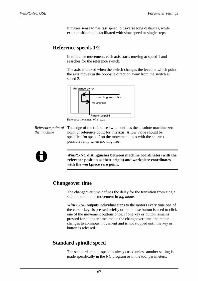
WinPC-NC USB Parameter settings
It makes sense to use fast speed to traverse long distances, whileexact positioning is facilitated with slow speed or single steps.
Reference speeds 1/2In reference movement, each axis starts moving at speed 1 andsearches for the reference switch.
The axis is braked when the switch changes the level, at which pointthe axis moves in the opposite direction away from the switch atspeed 2.
Reference movement of an axis
Reference point ofthe machine
The edge of the reference switch defines the absolute machine zeropoint or reference point for this axis. A low value should bespecified for speed 2 so the movement ends with the shortestpossible ramp when moving free.
i WinPC-NC distinguishes between machine coordinates (with thereference position as their origin) and workpiece coordinateswith the workpiece zero point.
Changeover timeThe changeover time defines the delay for the transition from singlestep to continuous movement in jog mode.
WinPC-NC outputs individual steps to the motors every time one ofthe cursor keys is pressed briefly or the mouse button is used to clickone of the movement buttons once. If one key or button remainspressed for a longer time, that is the changeover time, the motorchanges to coninous movement and is not stopped until the key orbutton is released.
Standard spindle speedThe standard spindle speed is always used unless another setting ismade specifically in the NC program or in the tool parameters.
- 67 -
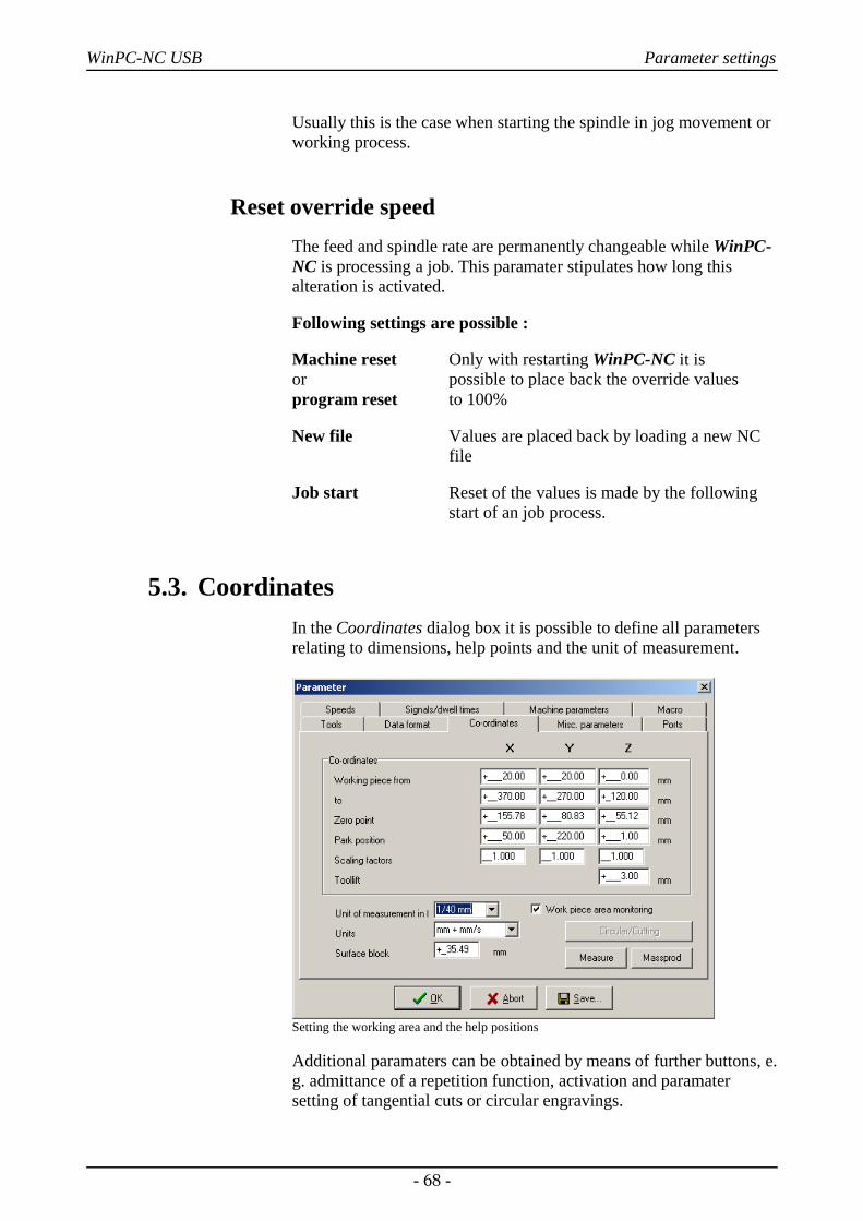
WinPC-NC USB Parameter settings
Usually this is the case when starting the spindle in jog movement orworking process.
Reset override speedThe feed and spindle rate are permanently changeable while WinPC-NC is processing a job. This paramater stipulates how long thisalteration is activated.
Following settings are possible :
Machine reset Only with restarting WinPC-NC it is or possible to place back the override valuesprogram reset to 100%
New file Values are placed back by loading a new NCfile
Job start Reset of the values is made by the following start of an job process.
5.3. CoordinatesIn the Coordinates dialog box it is possible to define all parametersrelating to dimensions, help points and the unit of measurement.
Setting the working area and the help positions
Additional paramaters can be obtained by means of further buttons, e.g. admittance of a repetition function, activation and paramatersetting of tangential cuts or circular engravings.
- 68 -
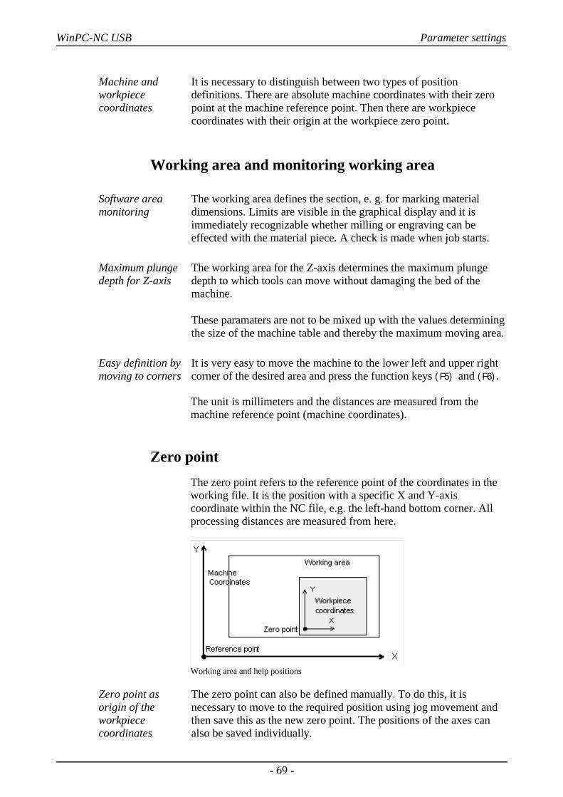
WinPC-NC USB Parameter settings
Machine andworkpiececoordinates
It is necessary to distinguish between two types of positiondefinitions. There are absolute machine coordinates with their zeropoint at the machine reference point. Then there are workpiececoordinates with their origin at the workpiece zero point.
Working area and monitoring working area
Software areamonitoring
The working area defines the section, e. g. for marking materialdimensions. Limits are visible in the graphical display and it isimmediately recognizable whether milling or engraving can beeffected with the material piece. A check is made when job starts.
Maximum plungedepth for Z-axis
The working area for the Z-axis determines the maximum plungedepth to which tools can move without damaging the bed of themachine.
These paramaters are not to be mixed up with the values determiningthe size of the machine table and thereby the maximum moving area.
Easy definition bymoving to corners
It is very easy to move the machine to the lower left and upper rightcorner of the desired area and press the function keys (F5) and (F6).
The unit is millimeters and the distances are measured from themachine reference point (machine coordinates).
Zero pointThe zero point refers to the reference point of the coordinates in theworking file. It is the position with a specific X and Y-axiscoordinate within the NC file, e.g. the left-hand bottom corner. Allprocessing distances are measured from here.
Working area and help positions
Zero point asorigin of theworkpiececoordinates
The zero point can also be defined manually. To do this, it isnecessary to move to the required position using jog movement andthen save this as the new zero point. The positions of the axes canalso be saved individually.
- 69 -
WinPC-NC USB Parameter settings
The unit is millimeters and the lengths represent the absolute distancefrom the machine reference point (machine coordinates).
Park position
Defined positionfor breaks
It is necessary to define a park position if the machine slide is to bemoved out of the working area at certain times. This may benecessary for a tool change, for example, or for clamping theworkpiece.
It is also possible to make this definition during jog movement bymoving into position with the keyboard or mouse.
The parked position can be moved to in jog movement orautomatically during a tool change and at the end of a workingprocess.
The unit is millimeters and the distances are measured from themachine reference point (machine coordinates).
Scaling factorsIt is possible to compensate for calibration differences using thescaling factors. If both the axis resolution and the unit ofmeasurement are set correctly but the machine does not move to theexact length nevertheless, this problem can be corrected using thescaling factors.
The values must be specified to 3 decimal places and are used formultiplying the coordinate values to which the machine is to move. Itaffects the imported NC data only.
Tool lift
Additionalclearance foravoiding collisions
It is possible to define an additional height above the zero point levelof the Z-axis as a safety clearance. The tool is lifted above the zeropoint by this distance during every unproductive movement withrapid speed and the new height is used as tool lift height.
On the next plunge movement, WinPC-NC first covers the safetyclearance down to the zero point at high speed, before pressing intothe material with the defined plunge speed.
- 70 -
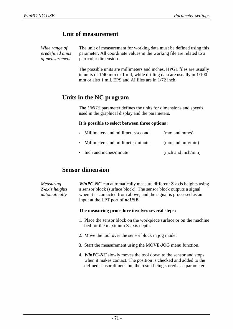
WinPC-NC USB Parameter settings
Unit of measurement
Wide range ofpredefined units of measurement
The unit of measurement for working data must be defined using thisparameter. All coordinate values in the working file are related to aparticular dimension.
The possible units are millimeters and inches. HPGL files are usuallyin units of 1/40 mm or 1 mil, while drilling data are usually in 1/100mm or also 1 mil. EPS and AI files are in 1/72 inch.
Units in the NC programThe UNITS parameter defines the units for dimensions and speedsused in the graphical display and the parameters.
It is possible to select between three options :
• Millimeters and millimeter/second (mm and mm/s)
• Millimeters and millimeter/minute (mm and mm/min)
• Inch and inches/minute (inch and inch/min)
Sensor dimension
Measuring Z-axis heightsautomatically
WinPC-NC can automatically measure different Z-axis heights usinga sensor block (surface block). The sensor block outputs a signalwhen it is contacted from above, and the signal is processed as aninput at the LPT port of ncUSB.
The measuring procedure involves several steps:
1. Place the sensor block on the workpiece surface or on the machinebed for the maximum Z-axis depth.
2. Move the tool over the sensor block in jog mode.
3. Start the measurement using the MOVE-JOG menu function.
4. WinPC-NC slowly moves the tool down to the sensor and stopswhen it makes contact. The position is checked and added to thedefined sensor dimension, the result being stored as a parameter.
- 71 -
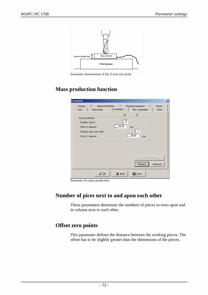
WinPC-NC USB Parameter settings
Automatic measurement of the Z-axis zero point
Mass production function
Parameter for mass production
Number of pices next to and apon each otherThese paramaters determine the numbers of pieces in rows apon andin column next to each other.
Offset zero pointsThis paramater defines the distance between the working pieces. Theoffset has to be slightly greater than the dimensions of the pieces.
- 72 -
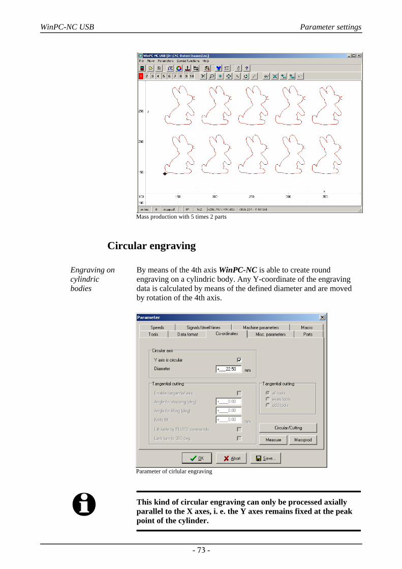
WinPC-NC USB Parameter settings
Mass production with 5 times 2 parts
Circular engraving
Engraving oncylindric bodies
By means of the 4th axis WinPC-NC is able to create roundengraving on a cylindric body. Any Y-coordinate of the engravingdata is calculated by means of the defined diameter and are movedby rotation of the 4th axis.
Parameter of cirlular engraving
i This kind of circular engraving can only be processed axiallyparallel to the X axes, i. e. the Y axes remains fixed at the peakpoint of the cylinder.
- 73 -
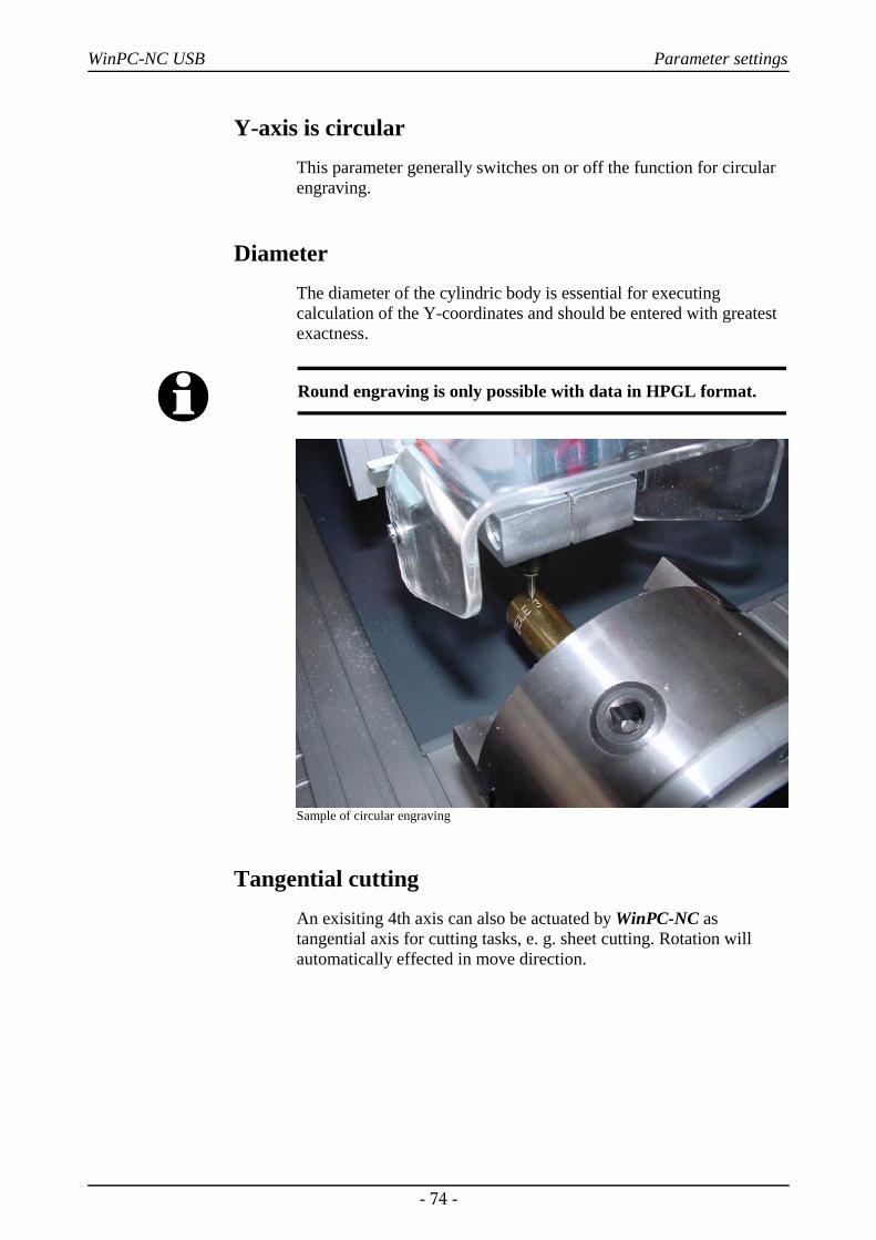
WinPC-NC USB Parameter settings
Y-axis is circularThis parameter generally switches on or off the function for circularengraving.
DiameterThe diameter of the cylindric body is essential for executingcalculation of the Y-coordinates and should be entered with greatestexactness.
i Round engraving is only possible with data in HPGL format.
Sample of circular engraving
Tangential cuttingAn exisiting 4th axis can also be actuated by WinPC-NC astangential axis for cutting tasks, e. g. sheet cutting. Rotation willautomatically effected in move direction.
- 74 -
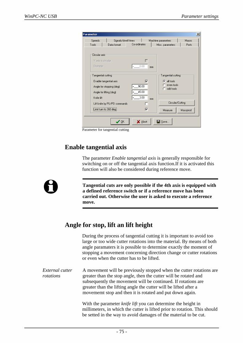
WinPC-NC USB Parameter settings
Parameter for tangential cutting
Enable tangential axisThe parameter Enable tangential axis is generally responsible forswitching on or off the tangential axis function.If it is activated thisfunction will also be considered during reference move.
i Tangential cuts are only possible if the 4th axis is equipped witha defined reference switch or if a reference move has beencarried out. Otherwise the user is asked to execute a referencemove.
Angle for stop, lift an lift heightDuring the process of tangential cutting it is important to avoid toolarge or too wide cutter rotations into the material. By means of bothangle paramaters it is possible to determine exactly the moment ofstopping a movement concerning direction change or cutter rotationsor even when the cutter has to be lifted.
External cutterrotations
A movement will be previously stopped when the cutter rotations aregreater than the stop angle, then the cutter will be rotated andsubsequently the movement will be continued. If rotations aregreater than the lifting angle the cutter will be lifted after amovememt stop and then it is rotated and put down again.
With the parameter knife lift you can determine the height inmillimeters, in which the cutter is lifted prior to rotation. This shouldbe setted in the way to avoid damages of the material to be cut.
- 75 -
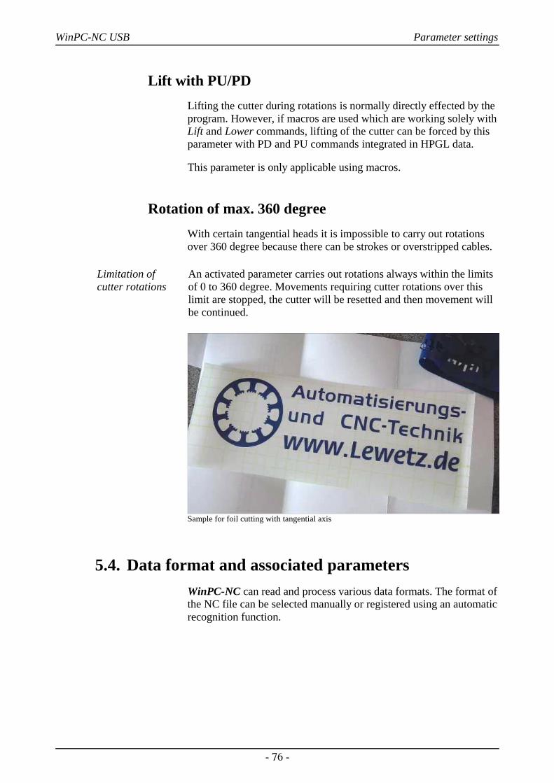
WinPC-NC USB Parameter settings
Lift with PU/PDLifting the cutter during rotations is normally directly effected by theprogram. However, if macros are used which are working solely withLift and Lower commands, lifting of the cutter can be forced by thisparameter with PD and PU commands integrated in HPGL data.
This parameter is only applicable using macros.
Rotation of max. 360 degreeWith certain tangential heads it is impossible to carry out rotationsover 360 degree because there can be strokes or overstripped cables.
Limitation ofcutter rotations
An activated parameter carries out rotations always within the limitsof 0 to 360 degree. Movements requiring cutter rotations over thislimit are stopped, the cutter will be resetted and then movement willbe continued.
Sample for foil cutting with tangential axis
5.4. Data format and associated parametersWinPC-NC can read and process various data formats. The format ofthe NC file can be selected manually or registered using an automaticrecognition function.
- 76 -
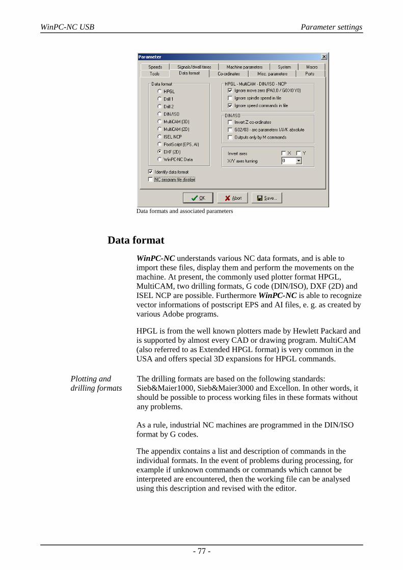
WinPC-NC USB Parameter settings
Data formats and associated parameters
Data formatWinPC-NC understands various NC data formats, and is able toimport these files, display them and perform the movements on themachine. At present, the commonly used plotter format HPGL,MultiCAM, two drilling formats, G code (DIN/ISO), DXF (2D) andISEL NCP are possible. Furthermore WinPC-NC is able to recognizevector informations of postscript EPS and AI files, e. g. as created byvarious Adobe programs.
HPGL is from the well known plotters made by Hewlett Packard andis supported by almost every CAD or drawing program. MultiCAM(also referred to as Extended HPGL format) is very common in theUSA and offers special 3D expansions for HPGL commands.
Plotting anddrilling formats
The drilling formats are based on the following standards:Sieb&Maier1000, Sieb&Maier3000 and Excellon. In other words, itshould be possible to process working files in these formats withoutany problems.
As a rule, industrial NC machines are programmed in the DIN/ISOformat by G codes.
The appendix contains a list and description of commands in theindividual formats. In the event of problems during processing, forexample if unknown commands or commands which cannot beinterpreted are encountered, then the working file can be analysedusing this description and revised with the editor.
- 77 -
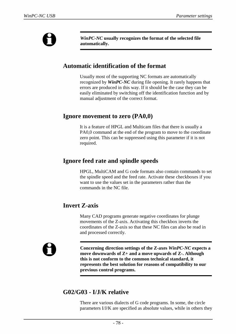
WinPC-NC USB Parameter settings
i WinPC-NC usually recognizes the format of the selected fileautomatically.
Automatic identification of the formatUsually most of the supporting NC formats are automaticallyrecognized by WinPC-NC during file opening. It rarely happens thaterrors are produced in this way. If it should be the case they can beeasily eliminated by switching off the identification function and bymanual adjustment of the correct format.
Ignore movement to zero (PA0,0) It is a feature of HPGL and Multicam files that there is usually aPA0,0 command at the end of the program to move to the coordinatezero point. This can be suppressed using this parameter if it is notrequired.
Ignore feed rate and spindle speedsHPGL, MultiCAM and G code formats also contain commands to setthe spindle speed and the feed rate. Activate these checkboxes if youwant to use the values set in the parameters rather than thecommands in the NC file.
Invert Z-axisMany CAD programs generate negative coordinates for plungemovements of the Z-axis. Activating this checkbox inverts thecoordinates of the Z-axis so that these NC files can also be read inand processed correctly.
i Concerning direction settings of the Z-axes WinPC-NC expects amove downwards of Z+ and a move upwards of Z-. Althoughthis is not conform to the common technical standard, itrepresents the best solution for reasons of compatibility to ourprevious control programs.
G02/G03 - I/J/K relative There are various dialects of G code programs. In some, the circleparameters I/J/K are specified as absolute values, while in others they
- 78 -
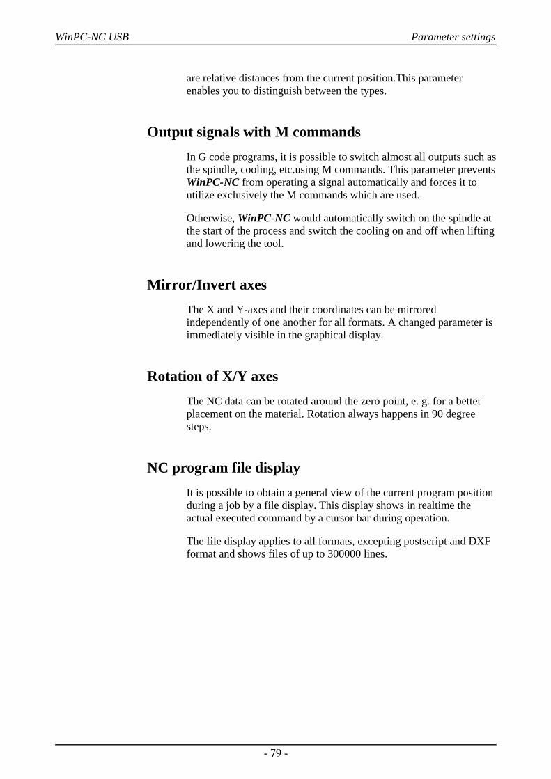
WinPC-NC USB Parameter settings
are relative distances from the current position.This parameterenables you to distinguish between the types.
Output signals with M commandsIn G code programs, it is possible to switch almost all outputs such asthe spindle, cooling, etc.using M commands. This parameter preventsWinPC-NC from operating a signal automatically and forces it toutilize exclusively the M commands which are used.
Otherwise, WinPC-NC would automatically switch on the spindle atthe start of the process and switch the cooling on and off when liftingand lowering the tool.
Mirror/Invert axesThe X and Y-axes and their coordinates can be mirroredindependently of one another for all formats. A changed parameter isimmediately visible in the graphical display.
Rotation of X/Y axesThe NC data can be rotated around the zero point, e. g. for a betterplacement on the material. Rotation always happens in 90 degreesteps.
NC program file displayIt is possible to obtain a general view of the current program positionduring a job by a file display. This display shows in realtime theactual executed command by a cursor bar during operation.
The file display applies to all formats, excepting postscript and DXFformat and shows files of up to 300000 lines.
- 79 -
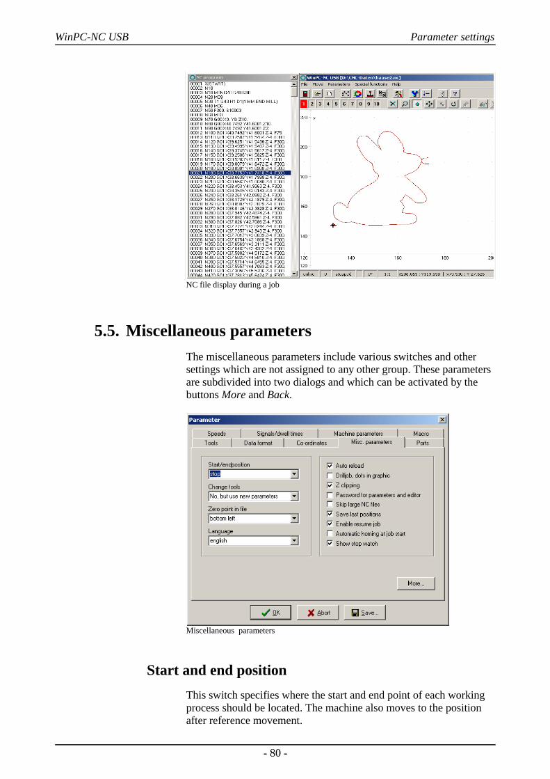
WinPC-NC USB Parameter settings
NC file display during a job
5.5. Miscellaneous parametersThe miscellaneous parameters include various switches and othersettings which are not assigned to any other group. These parametersare subdivided into two dialogs and which can be activated by thebuttons More and Back.
Miscellaneous parameters
Start and end positionThis switch specifies where the start and end point of each workingprocess should be located. The machine also moves to the positionafter reference movement.
- 80 -
WinPC-NC USB Parameter settings
There are 4 possible start and end positions :
Stop WinPC-NC stops at the reference position after reference movement, and at the last coordinate after each job process
Zero point The machine moves to the defined zero point after reference movement and after each job process.
Park position WinPC-NC moves to the defined parked position after reference movement and after each job process.
Zero point + The machine moves to the defined zero pointtoollift and lifts up the tool to the defined toollift
height.
It is a good idea to move to a certain position after the workingprocess if space is required in order to change the workpiece.
Tool change The parameter defines how WinPC-NC handles the tool changecommands during a working process.
There are 5 possibilities for the tool change :
NO No tool change is performed, the entire working process takes place with the current tool
YES Performs the tool change and remains stopped in thecurrent position for every tool change
YES at Performs the tool change and moves to the definedpark position park position for every tool change
NO but use No tool change is performed, although the valuesnew values for plunge depth, plunge speed and feed speed of
the new tool are adopted.
YES by ATC Performs automatically a tool change by existing tool changer
Zero point in fileThe workpiece zero point is the point in the NC file which has itsposition defined in the coordinate parameters.However, it can belocated at various points inside or outside the workpiece and thesepoints are defined here.
- 81 -
WinPC-NC USB Parameter settings
Six positions are possible :
Bottom left The zero point is at the smallest X and Y-axis coordinates in the file, normally at the bottom left edge. Mostly used with HPGL files.
Origin of The zero point is at the coordinate origin, i.e.Coordinates where the CAD programs places it for the output. N
This setting is to be recommended if several files are being used on the same workpiece, e.g. routing and drilling a board or when using G code files.
Center The zero point is in the middle of the workpiece, i.e.exactly in the center of the coordinate dimensions in the X and Y-axis directions. This setting is usefulfor processing round workpieces, e.g. plates.
Bottom right The zero point is positioned at the highest X and smallest Y coordinate of the file.
Middle right The zero point is positioned at the highest X coordinate and exactly between the smallest and highest Y coordinate.
Top left The zero point is positioned at the smallest X and the highest Y coordinate of the file.
LanguageWinPC-NC is multilingual. The standard version already includes afew languages, and additional languages can easily be bolted on ifrequired. The available languages are listed in a menu.
According to the status of April 2015 seventeen most importantlanguages are available.
i The language changeover takes place as soon as you select a newlanguage and click Save. Some text phrases are available withcertain country drivers in Windows only.
Automatic reloadThe reload function continuously monitors the date and time of thecurrently loaded file and reloads the newly modified file if there is adiscrepancy.
Using this function, for example, it is possible to edit an NC file inthe drawing program, make continuous changes to it and then, when
- 82 -
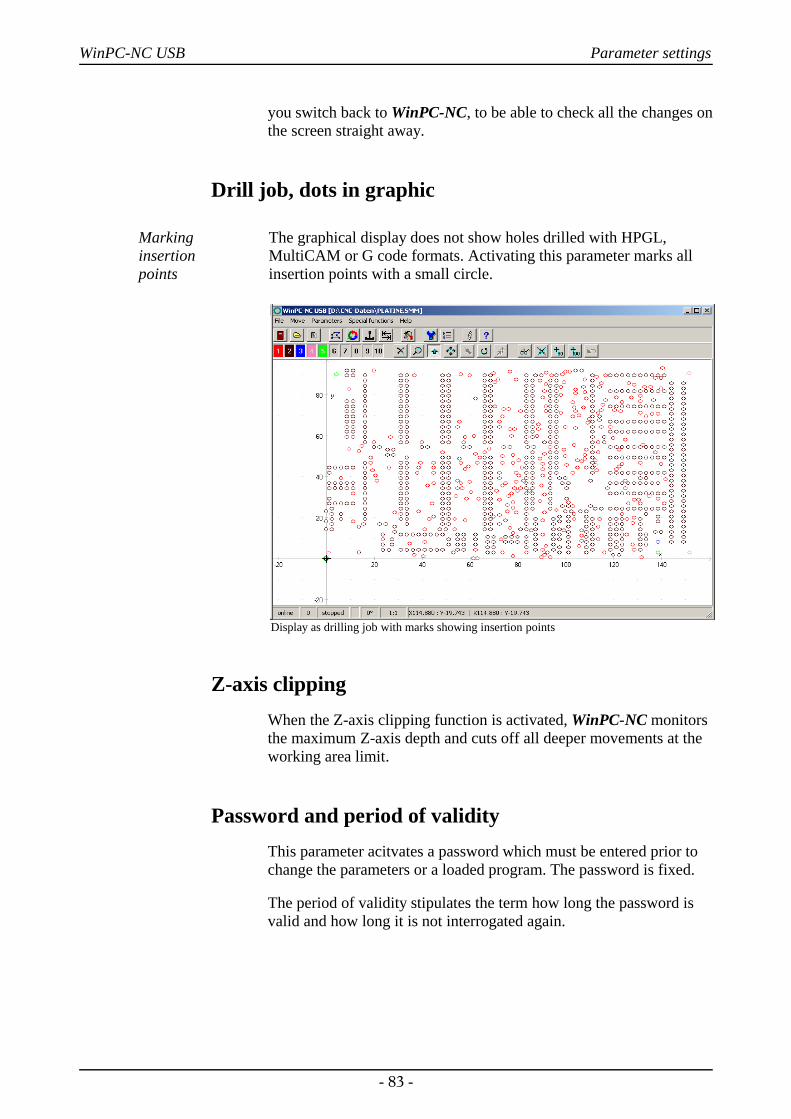
WinPC-NC USB Parameter settings
you switch back to WinPC-NC, to be able to check all the changes onthe screen straight away.
Drill job, dots in graphic
Marking insertion points
The graphical display does not show holes drilled with HPGL,MultiCAM or G code formats. Activating this parameter marks allinsertion points with a small circle.
Display as drilling job with marks showing insertion points
Z-axis clippingWhen the Z-axis clipping function is activated, WinPC-NC monitorsthe maximum Z-axis depth and cuts off all deeper movements at theworking area limit.
Password and period of validityThis parameter acitvates a password which must be entered prior tochange the parameters or a loaded program. The password is fixed.
The period of validity stipulates the term how long the password isvalid and how long it is not interrogated again.
- 83 -
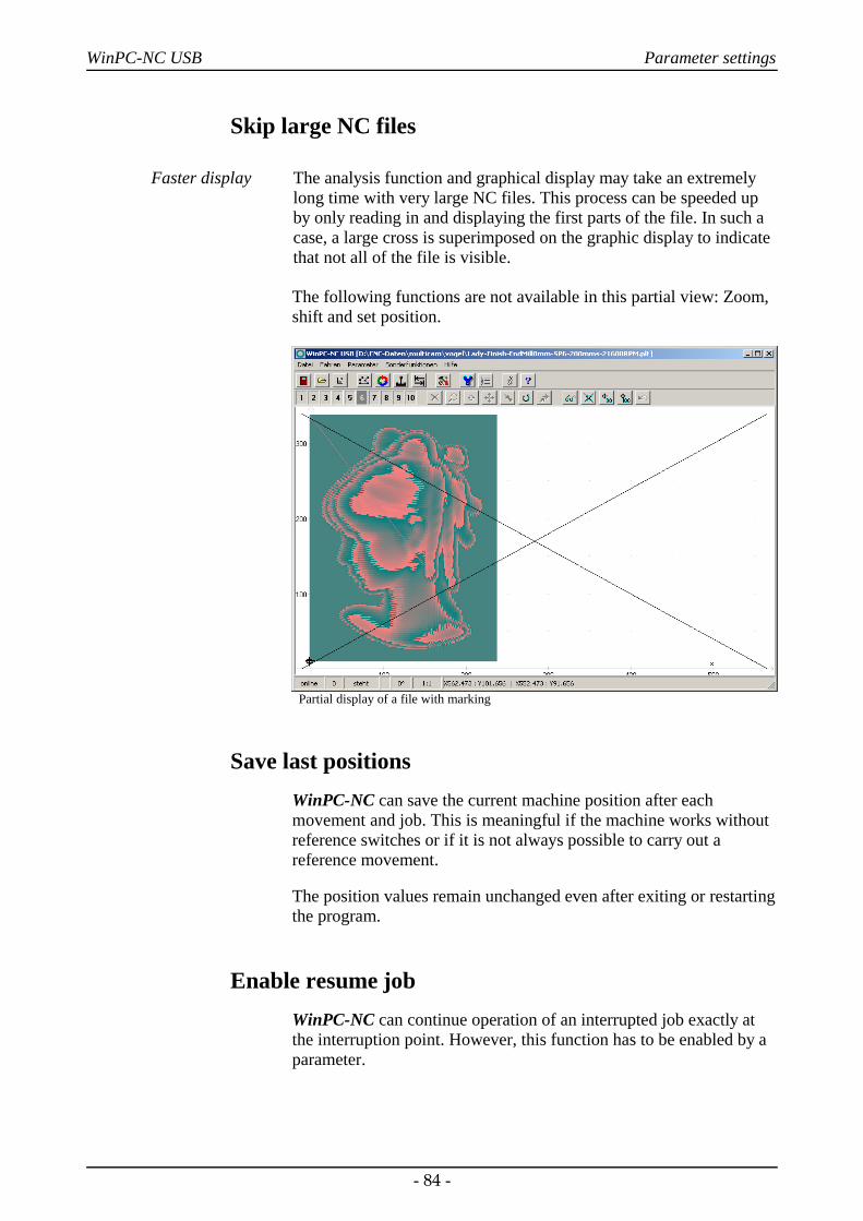
WinPC-NC USB Parameter settings
Skip large NC files
Faster display The analysis function and graphical display may take an extremelylong time with very large NC files. This process can be speeded upby only reading in and displaying the first parts of the file. In such acase, a large cross is superimposed on the graphic display to indicatethat not all of the file is visible.
The following functions are not available in this partial view: Zoom,shift and set position.
Partial display of a file with marking
Save last positionsWinPC-NC can save the current machine position after eachmovement and job. This is meaningful if the machine works withoutreference switches or if it is not always possible to carry out areference movement.
The position values remain unchanged even after exiting or restartingthe program.
Enable resume jobWinPC-NC can continue operation of an interrupted job exactly atthe interruption point. However, this function has to be enabled by aparameter.
- 84 -
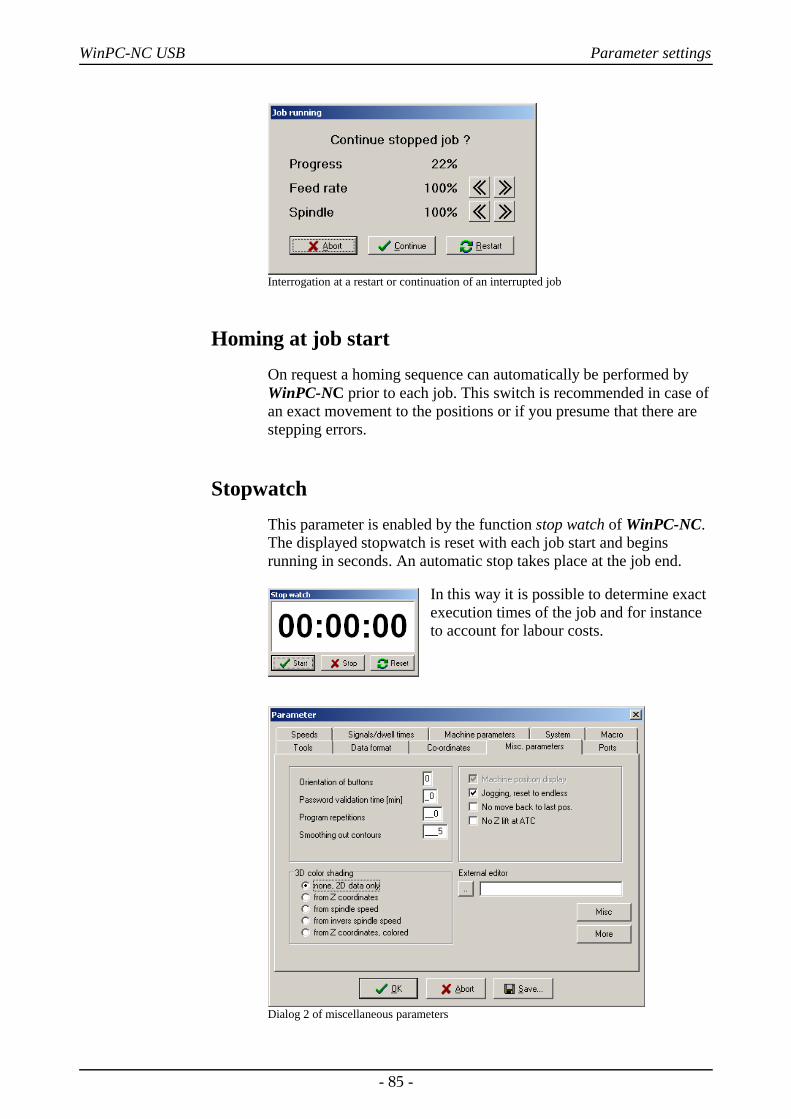
WinPC-NC USB Parameter settings
Interrogation at a restart or continuation of an interrupted job
Homing at job startOn request a homing sequence can automatically be performed byWinPC-NC prior to each job. This switch is recommended in case ofan exact movement to the positions or if you presume that there arestepping errors.
StopwatchThis parameter is enabled by the function stop watch of WinPC-NC.The displayed stopwatch is reset with each job start and beginsrunning in seconds. An automatic stop takes place at the job end.
In this way it is possible to determine exactexecution times of the job and for instanceto account for labour costs.
Dialog 2 of miscellaneous parameters
- 85 -
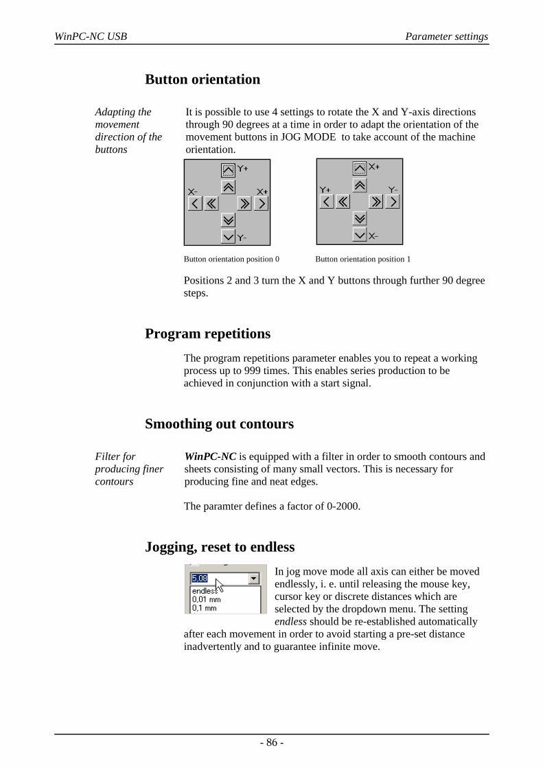
WinPC-NC USB Parameter settings
Button orientation
Adapting themovementdirection of thebuttons
It is possible to use 4 settings to rotate the X and Y-axis directionsthrough 90 degrees at a time in order to adapt the orientation of themovement buttons in JOG MODE to take account of the machineorientation.
Button orientation position 0 Button orientation position 1
Positions 2 and 3 turn the X and Y buttons through further 90 degreesteps.
Program repetitionsThe program repetitions parameter enables you to repeat a workingprocess up to 999 times. This enables series production to beachieved in conjunction with a start signal.
Smoothing out contours
Filter forproducing finercontours
WinPC-NC is equipped with a filter in order to smooth contours andsheets consisting of many small vectors. This is necessary forproducing fine and neat edges.
The paramter defines a factor of 0-2000.
Jogging, reset to endlessIn jog move mode all axis can either be movedendlessly, i. e. until releasing the mouse key,cursor key or discrete distances which areselected by the dropdown menu. The settingendless should be re-established automatically
after each movement in order to avoid starting a pre-set distanceinadvertently and to guarantee infinite move.
- 86 -
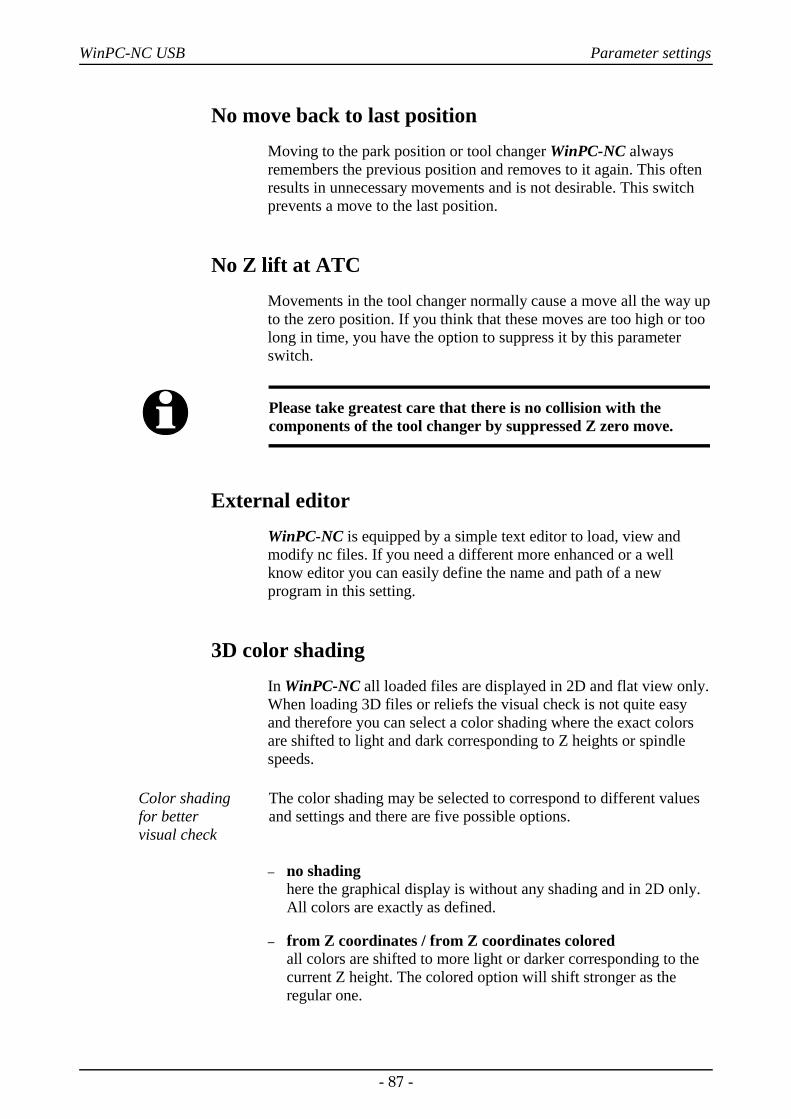
WinPC-NC USB Parameter settings
No move back to last positionMoving to the park position or tool changer WinPC-NC alwaysremembers the previous position and removes to it again. This oftenresults in unnecessary movements and is not desirable. This switchprevents a move to the last position.
No Z lift at ATCMovements in the tool changer normally cause a move all the way upto the zero position. If you think that these moves are too high or toolong in time, you have the option to suppress it by this parameterswitch.
i Please take greatest care that there is no collision with thecomponents of the tool changer by suppressed Z zero move.
External editorWinPC-NC is equipped by a simple text editor to load, view andmodify nc files. If you need a different more enhanced or a wellknow editor you can easily define the name and path of a newprogram in this setting.
3D color shadingIn WinPC-NC all loaded files are displayed in 2D and flat view only.When loading 3D files or reliefs the visual check is not quite easyand therefore you can select a color shading where the exact colorsare shifted to light and dark corresponding to Z heights or spindlespeeds.
Color shading for better visual check
The color shading may be selected to correspond to different valuesand settings and there are five possible options.
– no shadinghere the graphical display is without any shading and in 2D only.All colors are exactly as defined.
– from Z coordinates / from Z coordinates colored all colors are shifted to more light or darker corresponding to thecurrent Z height. The colored option will shift stronger as theregular one.
- 87 -
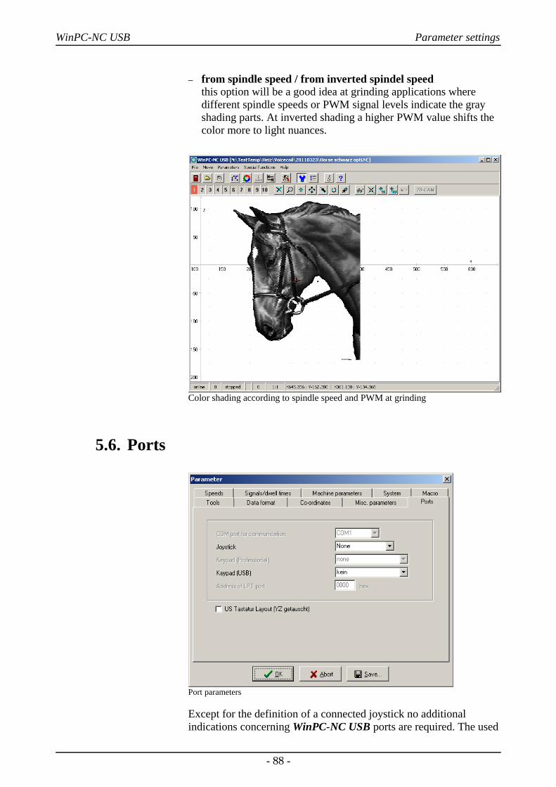
WinPC-NC USB Parameter settings
– from spindle speed / from inverted spindel speedthis option will be a good idea at grinding applications wheredifferent spindle speeds or PWM signal levels indicate the grayshading parts. At inverted shading a higher PWM value shifts thecolor more to light nuances.
Color shading according to spindle speed and PWM at grinding
5.6. Ports
Port parameters
Except for the definition of a connected joystick no additionalindications concerning WinPC-NC USB ports are required. The used
- 88 -
WinPC-NC USB Parameter settings
USB port is automatically ascertained and communication to ncUSBis established.
JoystickIf you want to use a joystick to set up the machine, you must use thisparameter to define the game port used.
i A connected joystick must be configured in the Windows systemprior to use and must be calibrated with a special function.
A connected Space Mouse of 3DConnexion must be selected bydifferent setting and all needed drivers must be installed prior to firstuse.
Keypad (USB)A remote control for WinPC-NC USB using numerical keypads ispossible and can be defined with this setting. There are predefinedOEM types available or a regular USB type keypad.
US keyboard layout (switch YZ keys)In manual jogging you can easily move axes by pressing the (X) or(Y) or (Z) key and in combination with (Ctrl) key you even can movefaster. As a difference betweed european and american keyboardlayout the (Y) and (Z) keys are switches which makes it extremelydifficult to move the machine.
By checking this checkbox WinPC-NC automatically corrects theswitched key layout.
5.7. Signals and dwell timesAll input signals and associated parameters are grouped in a separatedialog box.
- 89 -
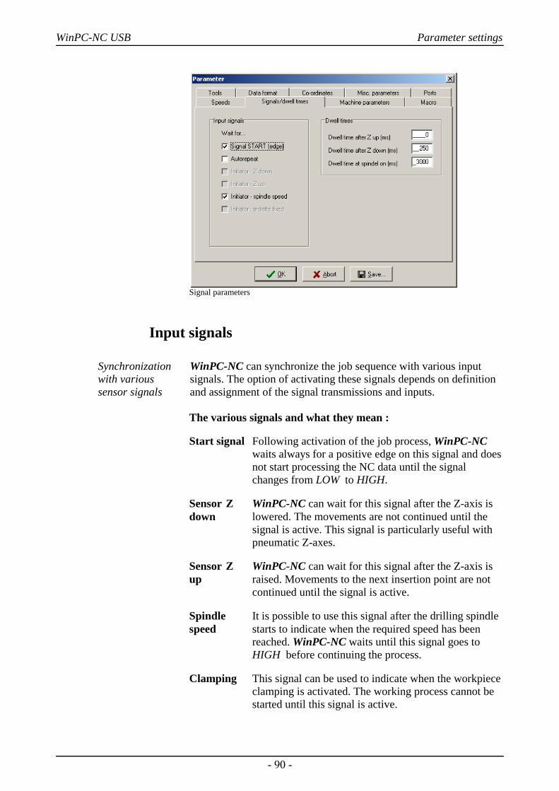
WinPC-NC USB Parameter settings
Signal parameters
Input signals
Synchronizationwith varioussensor signals
WinPC-NC can synchronize the job sequence with various inputsignals. The option of activating these signals depends on definitionand assignment of the signal transmissions and inputs.
The various signals and what they mean :
Start signal Following activation of the job process, WinPC-NC waits always for a positive edge on this signal and doesnot start processing the NC data until the signal changes from LOW to HIGH.
Sensor Z WinPC-NC can wait for this signal after the Z-axis isdown lowered. The movements are not continued until the
signal is active. This signal is particularly useful with pneumatic Z-axes.
Sensor Z WinPC-NC can wait for this signal after the Z-axis isup raised. Movements to the next insertion point are not
continued until the signal is active.
Spindle It is possible to use this signal after the drilling spindlespeed starts to indicate when the required speed has been
reached. WinPC-NC waits until this signal goes to HIGH before continuing the process.
Clamping This signal can be used to indicate when the workpiece clamping is activated. The working process cannot be started until this signal is active.
- 90 -
WinPC-NC USB Parameter settings
Automatic repeat
Perform the processrepeatedly
When the start signal is active, it is possible to use this parameter tomake WinPC-NC wait for the next start signal as soon as it finishesa working process. This means no input from the keyboard or mouseis required.
Dwell time after Z up and Z downIn many applications, it is a good idea or indeed a requirement towait a moment after the tool has been lowered or raised, beforestarting X and Y-axis movements. This may be the case whenworking with flexible materials or if you want the tool to freewheel.
The waiting time is defined in milliseconds.
Spindle acceleration time
Acceleration time for drillingspindle
The start delay defines a waiting time in milliseconds which alwayscounts down when the additional Drilling spindle output signal isactivated.
This ensures that the drilling spindle has enough time to acceleratebefore it is used for the first time.
5.8. Machine-specific parametersMachine-specific parameters include all settings which relate to themechanical characteristics of the machine. Only some or even noneof these parameters are present in certain OEM versions of WinPC-NC. Instead, the parameters will have already been set correctly inadvance for the machine in question.
i Always take the greatest possible care when setting or modifyingany machine-specific parameters, in order to avoid machinedefects.
For a better view the machine parameters are grouped in furtherwindows which can be displayed by clicking the correspondingbuttons.
- 91 -

WinPC-NC USB Parameter settings
Machine-specific parameters
Axis resolutionThe resolution boxes define the number of motorsteps per rotation. Ifyou are using gear units or step down/step up ratios, you can enter thecalculated values here directly.
The unit is steps.
Distance per rotationYou have to use this parameter to define what distance is movedduring one motor rotation. Defining the axis resolution with twoparameters offers the advantage that no calculation inaccuracies canarise.
The unit is millimeters with decimal places.
Maximum speedYou should use the MOTOR TEST function to ascertain themaximum speed of each axis. This represents the absolute top limitspeed with which the axis can be moved.
WinPC-NC monitors the speed entries made in all other parameterwindows and always corrects them to the value defined here.
The unit is millimeters with decimal places.
- 92 -
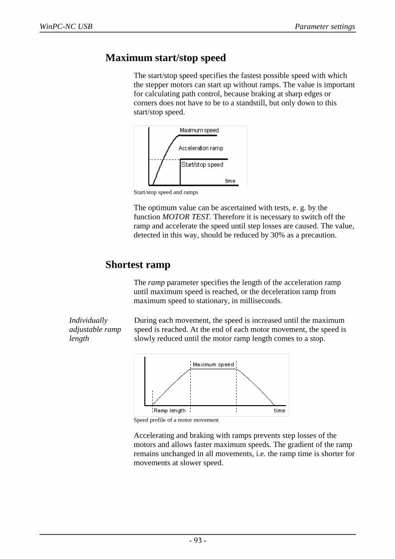
WinPC-NC USB Parameter settings
Maximum start/stop speedThe start/stop speed specifies the fastest possible speed with whichthe stepper motors can start up without ramps. The value is importantfor calculating path control, because braking at sharp edges orcorners does not have to be to a standstill, but only down to thisstart/stop speed.
Start/stop speed and ramps
The optimum value can be ascertained with tests, e. g. by thefunction MOTOR TEST. Therefore it is necessary to switch off theramp and accelerate the speed until step losses are caused. The value,detected in this way, should be reduced by 30% as a precaution.
Shortest rampThe ramp parameter specifies the length of the acceleration rampuntil maximum speed is reached, or the deceleration ramp frommaximum speed to stationary, in milliseconds.
Individuallyadjustable ramplength
During each movement, the speed is increased until the maximumspeed is reached. At the end of each motor movement, the speed isslowly reduced until the motor ramp length comes to a stop.
Speed profile of a motor movement
Accelerating and braking with ramps prevents step losses of themotors and allows faster maximum speeds. The gradient of the rampremains unchanged in all movements, i.e. the ramp time is shorter formovements at slower speed.
- 93 -
WinPC-NC USB Parameter settings
Invert movement directionThere are two possible remedies if one of the motors is moving in thewrong direction.
Changing over the movementdirection
Either swap over the motor winding connections or change themovement direction with this parameter. The direction signal forcontrolling the motor is then inverted before being output.
Reference switchThis parameter enables you to define in which direction the axis ismoved in order to search for the switch. Movement clear from theswitch then takes place in the opposite direction.
Reference sequenceReference movement of the individual axes takes place in a particularsequence. Usually, it is necessary to move the Z-axis upwards first soit is withdrawn from the workpiece. Then the two other axes move totheir reference points.
Possible faultswith referencemovement
After the machine is started up for the first time, there may be faultswith reference movement which can be remedied as follows:
• Axis moves in the wrong directionRemedy : Define that the reference switch is at the other
end of the axis.
• Axis moves in the correct direction, but stops after reaching the switch and does not move clear againRemedy : Define the reference switch at the other end and
change the switch logic.
Maximum spindle speed
Speed control in255 steps
WinPC-NC can control the speed of a drilling or milling spindle. It ispossible to define a speed for each tool, or the speed data is takenfrom the NC files.
The maximum value defines the reference for step 255. All lowervalues are calculated proportionately between 0 and this value, andare output.
- 94 -
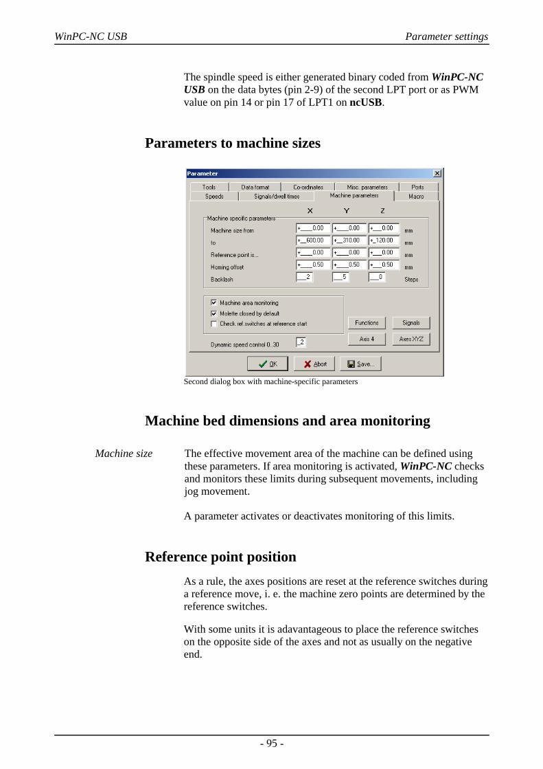
WinPC-NC USB Parameter settings
The spindle speed is either generated binary coded from WinPC-NCUSB on the data bytes (pin 2-9) of the second LPT port or as PWMvalue on pin 14 or pin 17 of LPT1 on ncUSB.
Parameters to machine sizes
Second dialog box with machine-specific parameters
Machine bed dimensions and area monitoring
Machine size The effective movement area of the machine can be defined usingthese parameters. If area monitoring is activated, WinPC-NC checksand monitors these limits during subsequent movements, includingjog movement.
A parameter activates or deactivates monitoring of this limits.
Reference point positionAs a rule, the axes positions are reset at the reference switches duringa reference move, i. e. the machine zero points are determined by thereference switches.
With some units it is adavantageous to place the reference switcheson the opposite side of the axes and not as usually on the negativeend.
- 95 -
WinPC-NC USB Parameter settings
Referencepositionsindividuallydefinable
With the paramater reference point is it is easy to instruct Win-PC-NC to set these specified positions on the reference switches and toplace the machine zero point to a desired position.
Reference offset
Safe moving freeof the referenceswitch
To avoid a stop directly at the reference switch's edge after areference and moving free it is possible to determine an additionalpath with the reference offset.This has to be carried out after movingfree from the switch. First after moving the offset the axis is resettedor the defined reference position is adjusted.
Typical values are 0.5 to 1mm additional distances to the switch.
Backlash compensationDrives which can not be adjusted absolutely close may causeinsignificant differences during reversal of dircection. Thesedifferences can be added up within the job process. This reversaldrive can be compensated by these paramaters.
Parameters for any axes are available in order to define the opencurcuit steps. The number of the motor steps are additionallyindicated with any direction reversal.
Standard value means 0 steps und should remain unchanged if drivesare closely adjusted.
Collet chuck closed at machine startUsing a changer or an automatic collet chuck this switch isresponsible for determining the status of the chuck during switch onof the plant. Activating the chuck closed WinPC-NC remembers thelast used tool from session to session.
Checking reference switches
Reference moveexclusive withvacant switches
Prior to a reference move the parameter induces WinPC-NC tocheck the switches. Only if each defined switch is vacant a referencemove can take place.
This test makes sense if several reference switches are connected onthe LPT port by a single input line and if it is not possible forWinPC-NC to recognize the axis currently placed on its switch.
- 96 -
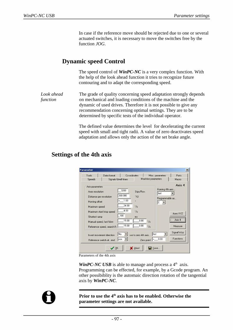
WinPC-NC USB Parameter settings
In case if the reference move should be rejected due to one or severalactuated switches, it is necessary to move the switches free by thefunction JOG.
Dynamic speed Control The speed control of WinPC-NC is a very complex function. Withthe help of the look ahead function it tries to recognize futurecontouring and to adapt the corresponding speed.
Look ahead function
The grade of quality concerning speed adaptation strongly dependson mechanical and loading conditions of the machine and thedynamic of used drives. Therefore it is not possible to give anyrecommendation concerning optimal settings. They are to bedetermined by specific tests of the individual operator.
The defined value determines the level for decelerating the currentspeed with small and tight radii. A value of zero deactivates speedadaptation and allows only the action of the set brake angle.
Settings of the 4th axis
Parameters of the 4th axis
WinPC-NC USB is able to manage and process a 4th axis.Programming can be effected, for example, by a Gcode program. Another possibiblity is the automaic direction rotation of the tangentialaxis by WinPC-NC.
i Prior to use the 4th axis has to be enabled. Otherwise theparameter settings are not available.
- 97 -
WinPC-NC USB Parameter settings
Some of the paramters as speeds, inverting the dircection andreference switch are acting in the same way as for axes XYZ and notexplained at this place.
i Parameter settings and programming of parallel axis with lettersU, V and W are made in mm and mm/sec. Settings of rotary axiswith letters A, B and C are made in degree and degree/sec.
Axis resolution/distance per rotationThe resolution parameters operate in the same way as the standard X,Y, Z axes. If you enter 360 or 36 as the distance per rotation, then you can program the 4th axis as a rotational axis in degrees or 1/10 ofa degree.
Homing offsetThe homing or reference offset defines the angle differential from thezero position after moving clear of the switch. WinPC-NC first looksfor the switch at search speed and then moves back from the switchin the opposite direction. Following this, the reference offset ismoved as a rotation round to the zero position.
Adjustingtangential cutter
Using the 4th axis as tangential axis the reference offset has to beadjusted in the way that the cutter edge shows in positive X directionafter the reference move.
Axis 4 programmable as
Letter forprogramming
The 4th axis can be addressed in G code programs using various axisletters. Axes parallel to X, Y, Z are normally designated U, V, W,while rotational axes in the X, Y, Z direction are programmed withA, B or C.
Homing sequence of 4th axisThe reference movement or move to zero point of the 4th axis can beperformed either before or after the other axes.
- 98 -
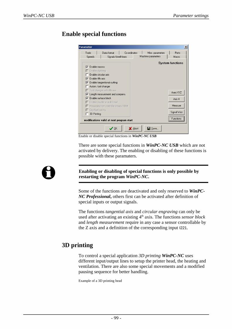
WinPC-NC USB Parameter settings
Enable special functions
Enable or disable special functions in WinPC-NC USB
There are some special functions in WinPC-NC USB which are notactivated by delivery. The enabling or disabling of these functions ispossible with these paramaters.
i Enabling or disabling of special functions is only possible byrestarting the program WinPC-NC.
Some of the functions are deactivated and only reserved to WinPC-NC Professional, others first can be activated after definition ofspecial inputs or output signals.
The functions tangential axis and circular engraving can only beused after activating an existing 4th axis. The functions sensor blockand length measurement require in any case a sensor controllable bythe Z axis and a definition of the corresponding input I221.
3D printingTo control a special application 3D printing WinPC-NC usesdifferent input/output lines to setup the printer head, the heating andventilation. There are also some special movements and a modifiedpausing sequence for better handling.
Example of a 3D printing head
- 99 -
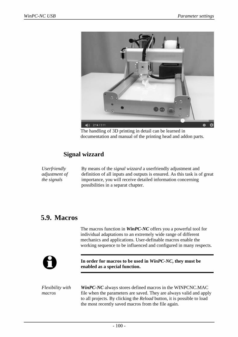
WinPC-NC USB Parameter settings
The handling of 3D printing in detail can be learned indocumentation and manual of the printing head and addon parts.
Signal wizzard
Userfriendlyadjustment of the signals
By means of the signal wizzard a userfriendly adjustment anddefinition of all inputs and outputs is ensured. As this task is of greatimportance, you will receive detailed information concerningpossibilities in a separat chapter.
5.9. MacrosThe macros function in WinPC-NC offers you a powerful tool forindividual adaptations to an extremely wide range of differentmechanics and applications. User-definable macros enable theworking sequence to be influenced and configured in many respects.
i In order for macros to be used in WinPC-NC, they must beenabled as a special function.
Flexibility withmacros
WinPC-NC always stores defined macros in the WINPCNC.MACfile when the parameters are saved. They are always valid and applyto all projects. By clicking the Reload button, it is possible to loadthe most recently saved macros from the file again.
- 100 -
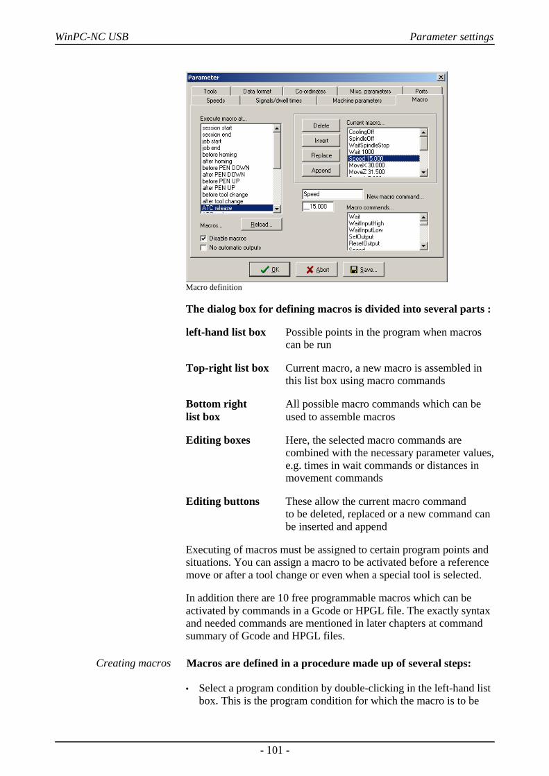
WinPC-NC USB Parameter settings
Macro definition
The dialog box for defining macros is divided into several parts :
left-hand list box Possible points in the program when macros can be run
Top-right list box Current macro, a new macro is assembled in this list box using macro commands
Bottom right All possible macro commands which can belist box used to assemble macros
Editing boxes Here, the selected macro commands are combined with the necessary parameter values,e.g. times in wait commands or distances in movement commands
Editing buttons These allow the current macro command to be deleted, replaced or a new command can be inserted and append
Executing of macros must be assigned to certain program points andsituations. You can assign a macro to be activated before a referencemove or after a tool change or even when a special tool is selected.
In addition there are 10 free programmable macros which can beactivated by commands in a Gcode or HPGL file. The exactly syntaxand needed commands are mentioned in later chapters at commandsummary of Gcode and HPGL files.
Creating macros Macros are defined in a procedure made up of several steps:
• Select a program condition by double-clicking in the left-hand listbox. This is the program condition for which the macro is to be
- 101 -
WinPC-NC USB Parameter settings
defined. The top right list box then either displays an existingmacro or No macro defined.
• Edit the required macro by double-clicking the lines you want tochange to transfer them to the editing box. There, you can definedifferent values for the commands. The new command is adoptedwhen you click Replace or Insert.
• In order to create new or partial macros, you have to select therequired command from the list box at the bottom right and thencomplete it in the editing boxes. Following this, the new commandcan be transferred into the current macro using Replace or Insert.
• To delete macro command, simply move the bar to thecorresponding command in the current macro and click the Deletebutton.
Macro commands Most of the macro commands are self-explanatory and therefore wewant to treat solely some special ones.
Wait time Performs a wait time in msWait InputHigh no Waits for HIGH level of input noSetOutputHigh no Sets output no HIGHSpeed spd Speed setting for future moves in
mm/secs.MoveX xxx Moves a relative distanceMoveAbs xxx Moves to absolute position xxx, i.e. in
machine coordinatesWaitStart Waits for a start signal on input
I255 StartOffsetX not availabale in WinPC-NC USB Block Z zero point not available in WinPC-NC USBSpindle Speed sets up a new spindle speed
i Defining inputs and outputs always requires the indication ofthe corresponding numbers. Do not indicate the pin number ofthe LPT port. Typical numbers to be used are I100 to I107 orQ100 to Q115. In advance it is necessary to assign to these inputsand outputs a pin numbers and wires via signal wizzard.
Example 1 Release tool
Example for releasing a tool in the changer magazine:
Speed 80,00 Set the speed to 80 mm/sMoveZ 156,34 Move down with the Z-axisSpeed 5,00 Set speed slower WaitSpindleStop Wait until spindle has stopped MoveY 10,00 Move the tool into the chuck holderMoletteOpen Open the moletteWait 500 Wait 500 ms for pneumatic systemSpeed 2,00 Set very slow speed
- 102 -
WinPC-NC USB Parameter settings
MoveZ -5,00 Move 5 mm up from toolSpeed 80,00 Set speed back to fastMoveZ -151,34 Move Z-axis all the way upMoveY -10,00 Move Y-axis back to starting position
Example 2Insertion whenflame cutting
Example of a macro defining an insertion procedure when flamecutting. It is always performed before PenDown commands.
MoveZ 50,00 Move down with the Z-axisWait 10000 Wait 10 seconds at pre-heating position 1MoveZ 20,00 Move down again by 20 mmWait 2000 Wait 2 seconds and pre-heatSetOutputHigh 100 switch on oxygen with output 100 Wait 500 Wait another 500 ms before movement
i Please note that certain macro commands like offset or macrosfor certain additional functions, e. g. Block zero Z, are onlyusable by WinPC-NC Professional.
No automatic outputs
Outputs automatic or with macros
Normally, WinPC-NC operates a few output signals automatically.For example, the Job in progress output is set at the start of aworking process and reset at the end or after a cancel. Equally, thefollowing signals are also set automatically: Drilling spindle,Coolant pump, Dispensing, etc.
If it is better for the signals to be operated with the macros or if youwant to change the times when they are operated, then you mustswitch off automatic operation with this parameter.
Following this, all signals can only be operated using macros.
Disable macrosUsing macros can be generally switched on or off by this parameter.
- 103 -
WinPC-NC USB Initial start-up with the machine
6. Initial start-up with the machine
Machineadjustment
After software installation on your PC it is necessary to carry outsome start-up processes and corresponding adjustments.
This procedure is only necessary with the initial start-up procedureand generally relates to the adjustment of your machine. In case ifyou have acquired WinPC-NC USB together with the machine eithermost of the paramaters are correctly preadjusted or you have receivedan additional disk with the corresponding adjustments. If this is thecase the following described procedure can be disregarded.
i The accessory module ncUSB is equipped with two ports whichare pin compatible and similar to LPT. To simplify matters, wecontinue using the term LPT port in this document.
6.1. Connecting ncUSB and the machineAfter software installation and connection of the accessory modulencUSB there should be the corresponding hardware identification.After a short time you will receive the message that the newlyidentified hardware is ready for use.
Connection of the machine and the drives is made on the first LPTport of ncUSB.
i Attention !
Greatest care has to be taken when connecting all cables to thehousing. Following actions can cause serious damage:Incorrect assignment of the signal cable, plug incorrectlyinserted, cables incorrectly connected.
Starting the entire unit is not allowed until all necessary and statespecific safety rules have been accomplished and checked. The useris responsible for unit operation.
- 104 -
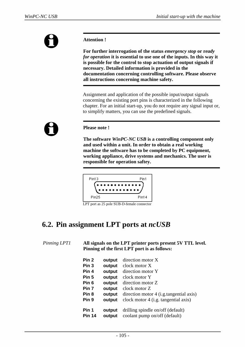
WinPC-NC USB Initial start-up with the machine
i Attention !
For further interrogation of the status emergency stop or readyfor operation it is essential to use one of the inputs. In this way itis possible for the control to stop actuation of output signals ifnecessary. Detailed information is provided in thedocumentation concerning controlling software. Please observeall instructions concerning machine safety.
Assignment and application of the possible input/output signalsconcerning the existing port pins is characterized in the followingchapter. For an initial start-up, you do not require any signal input or,to simplify matters, you can use the predefined signals.
i Please note !
The software WinPC-NC USB is a controlling component onlyand used within a unit. In order to obtain a real workingmachine the software has to be completed by PC equipment,working appliance, drive systems and mechanics. The user isresponsible for operation saftey.
LPT port as 25 pole SUB-D-female connector
6.2. Pin assignment LPT ports at ncUSB
Pinning LPT1 All signals on the LPT printer ports present 5V TTL level.Pinning of the first LPT port is as follows:
Pin 2 output direction motor XPin 3 output clock motor XPin 4 output direction motor YPin 5 output clock motor YPin 6 output direction motor ZPin 7 output clock motor ZPin 8 output direction motor 4 (i.g.tangential axis)Pin 9 output clock motor 4 (i.g. tangential axis)
Pin 1 output drilling spindle on/off (default)Pin 14 output coolant pump on/off (default)
- 105 -
WinPC-NC USB Initial start-up with the machine
Pin 16 output current reduction (default)Pin 17 output job running (default)
Pin 10 input reference switch X (default) Pin 11 input reference switch Y (default)Pin 12 input reference switch Z (default)Pin 13 input sensor/surface block (default)Pin 15 input free
Pin 18-25 signal mass (0V GND)
Pinning LPT2 Pinning of the second LPT port is as follows:
Pin 2-9 output analogeous output, 256 degrees binary coded
Pin 1 output freePin 14 output freePin 16 output freePin 17 output free
Pin 10 input free Pin 11 input freePin 12 input freePin 13 input freePin 15 input free
Pin 18-25 signal mass (0V GND)
User definableadditional in-/outputs
All inputs on pins 10, 11, 12, 13 and 15 as well as the additional pinoutputs 1, 14, 16 and 17 are free definable and assignable to thedesired signals. When the software is delivered above mentionnedsignals are assigned.
i The additional signal Q218 Spindle Speed/PWM, which is a veryimportant one, can only be connected on the pins LPT1:14 orLPT1:17.
The safety signal Q219 Toggle/Chargepump is available on thepins LPT1:16 or LPT1:17 only.
6.3. Determination of axis resolutionFor calculating the required distances and speeds it is necessary totell WinPC-NC precisely the defintion of the axis resolution.
- 106 -
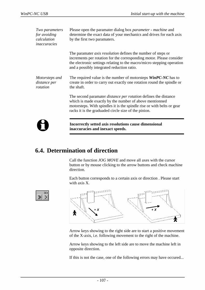
WinPC-NC USB Initial start-up with the machine
Two parametersfor avoidingcalculationinaccuracies
Please open the paramater dialog box parameter - machine anddetermine the exact data of your mechanics and drives for each axisby the first two paramaters.
The paramater axis resolution defines the number of steps orincrements per rotation for the corresponding motor. Please considerthe electronic settings relating to the macro/micro stepping operationand a possibly integrated reduction ratio.
Motorsteps anddistance perrotation
The required value is the number of motorsteps WinPC-NC has tocreate in order to carry out exactly one rotation round the spindle orthe shaft.
The second paramater distance per rotation defines the distancewhich is made exactly by the number of above mentionnedmotorsteps. With spindles it is the spindle rise or with belts or gearracks it is the graduaded circle size of the pinion.
i Incorrectly setted axis resolutions cause dimensionalinaccuracies and inexact speeds.
6.4. Determination of directionCall the function JOG MOVE and move all axes with the cursorbutton or by mouse clicking to the arrow buttons and check machinedirection.
Each button corresponds to a certain axis or direction . Please startwith axis X.
Arrow keys showing to the right side are to start a positive movementof the X-axis, i.e. following movement to the right of the machine.
Arrow keys showing to the left side are to move the machine left inopposite direction.
If this is not the case, one of the following errors may have occured...
- 107 -
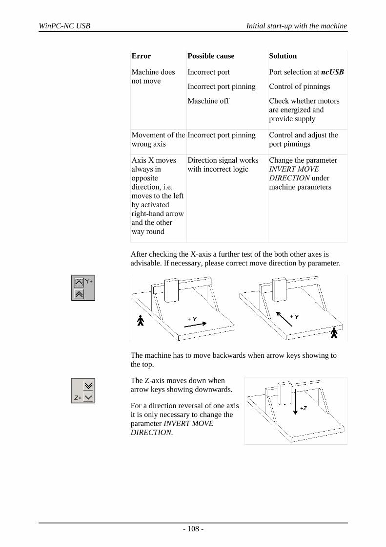
WinPC-NC USB Initial start-up with the machine
Error Possible cause Solution
Machine doesnot move
Incorrect port
Incorrect port pinning
Maschine off
Port selection at ncUSB
Control of pinnings
Check whether motorsare energized andprovide supply
Movement of thewrong axis
Incorrect port pinning Control and adjust theport pinnings
Axis X movesalways inoppositedirection, i.e.moves to the leftby activatedright-hand arrowand the otherway round
Direction signal workswith incorrect logic
Change the parameterINVERT MOVEDIRECTION undermachine parameters
After checking the X-axis a further test of the both other axes isadvisable. If necessary, please correct move direction by parameter.
The machine has to move backwards when arrow keys showing tothe top.
The Z-axis moves down whenarrow keys showing downwards.
For a direction reversal of one axisit is only necessary to change theparameter INVERT MOVEDIRECTION.
- 108 -
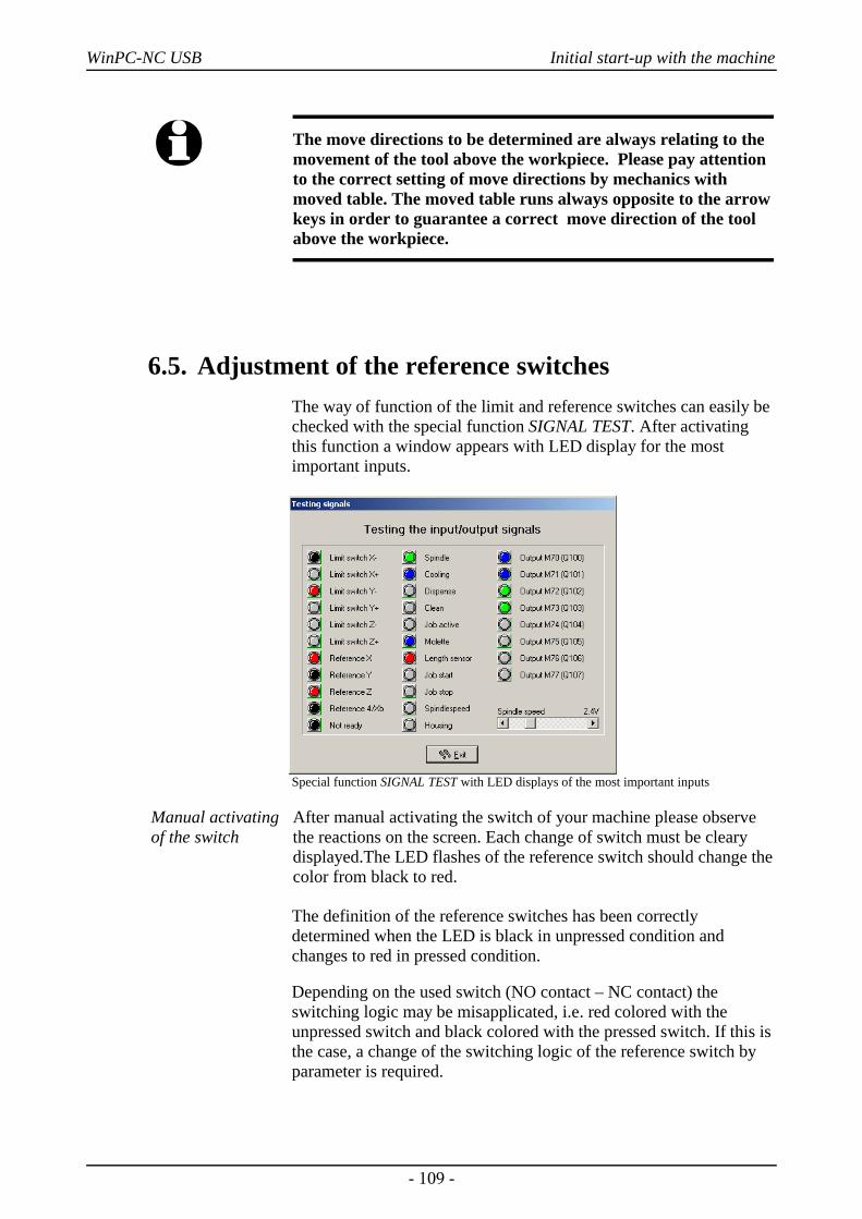
WinPC-NC USB Initial start-up with the machine
i The move directions to be determined are always relating to themovement of the tool above the workpiece. Please pay attentionto the correct setting of move directions by mechanics withmoved table. The moved table runs always opposite to the arrowkeys in order to guarantee a correct move direction of the toolabove the workpiece.
6.5. Adjustment of the reference switchesThe way of function of the limit and reference switches can easily bechecked with the special function SIGNAL TEST. After activatingthis function a window appears with LED display for the mostimportant inputs.
Special function SIGNAL TEST with LED displays of the most important inputs
Manual activatingof the switch
After manual activating the switch of your machine please observethe reactions on the screen. Each change of switch must be clearydisplayed.The LED flashes of the reference switch should change thecolor from black to red.
The definition of the reference switches has been correctlydetermined when the LED is black in unpressed condition andchanges to red in pressed condition.
Depending on the used switch (NO contact – NC contact) theswitching logic may be misapplicated, i.e. red colored with theunpressed switch and black colored with the pressed switch. If this isthe case, a change of the switching logic of the reference switch byparameter is required.
- 109 -
WinPC-NC USB Initial start-up with the machine
Determination ofswitching logic
Please carry out the following steps :
1. Open parameter dialog box parameter-machine-signals
2. Select the corresponding reference switch in left-hand window
3. Select the inverted entry in the drop-down menu below and acceptthe setting, e.g. change from LPT1 PIN 10 to LPT1 PIN10 INV
4. Save the latest setting and recheck by function SIGNAL TEST
A detailed description of the signal wizzard and the possibilities fordefining and setting the inputs and outputs is listed in the nextchapter.
6.6. Sequence and direction of reference moveIn the following step settings for reference move of the machine arestipulated. Please carry out the following steps:
1. Open parameter dialog box parameter-machine
2. Under reference switch at pos./neg. end you have to adjust onwhich axis side the switch is located. If it is not possible to bedirectly ascertained, change again to the function JOG MOVE andcheck by moving and oberserving the position counters and noteto which position the axes move to in the moment when they areapproaching the switch.
3. After the setting of all switches there is nothing else to do thanselecting the reference sequence. The desired sequence can bestipulated in the drop-down menu. Normally it is always the Z-axis which starts moving upon to it's switch followed by the otheraxes.
4. If you intend a reference move of one or several axes into positivedirection, it makes sense to place the machine zero point not at theswitch but define another position by parameter.
6.7. Control of settingsAfter respecting all items a reference move with your machine shouldnot cause any problems. Subsequent to the execution and saving ofall parameter settings please press the function key (F8) or select thecorresponding function by menu.
- 110 -
WinPC-NC USB Initial start-up with the machine
Reference movefor control
During the reference move all axes run upwards to their switchaccording to the adjusted sequence and then downwards the switchwith reduced speed. Exactly at the switching edge all axes arestopping and marking the reference point.
If this procedure should cause problems or stop with indicating errormessages some of the settings have been incorrectly carried out. Thetabulation below provides additional information concerningdifferent kinds of errors and corresponding solutions.
Error Solution
Axis moves into wrong direction
Define the reference switch at theother end
Axis moves into correctdirection, but very slowly
Switching logic has been adjustedincorrectly and has to be invertedand define the reference switch at theother end
Axis moves slowly into correct direction, but stops on the switch
Switching logic has been adjustedincorrectly and has to be invertedand define the reference switch at theother end
Axis moves very slowly intowrong direction
Switching logic has been adjustedincorrectly and has to be inverted
6.8. Additional stepsThe most important tasks have been finished by connecting themachine and setting the paramaters. Additional actions arerecommended in the following sequence :
1. Determination of the optimal ramps and speeds of all axes by thespecial function MOTOR TEST.
2. Determination of further speeds for JOG MOVE andREFERENCE MOVE by these values.
3. Desired functions can be enabled under parameter-machine-functions.
4. Connecting additional desired and required input and outputsignals definable by the signal wizzard.
- 111 -
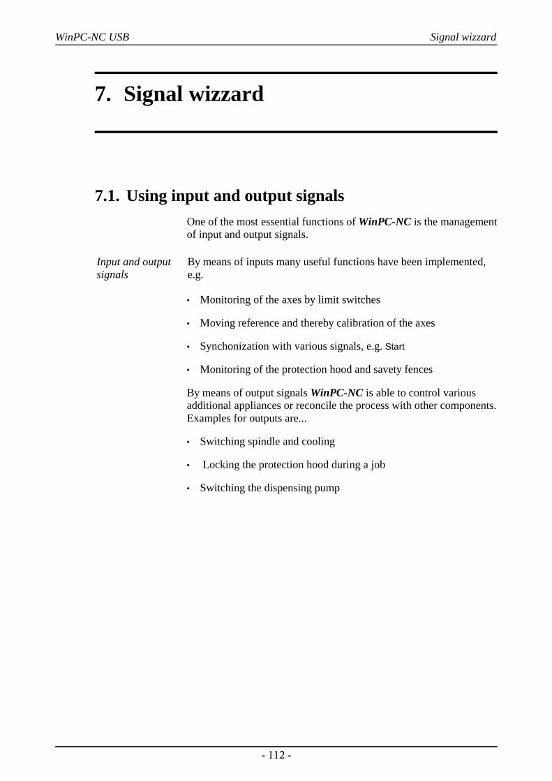
WinPC-NC USB Signal wizzard
7. Signal wizzard
7.1. Using input and output signalsOne of the most essential functions of WinPC-NC is the managementof input and output signals.
Input and outputsignals
By means of inputs many useful functions have been implemented,e.g.
• Monitoring of the axes by limit switches
• Moving reference and thereby calibration of the axes
• Synchonization with various signals, e.g. Start
• Monitoring of the protection hood and savety fences
By means of output signals WinPC-NC is able to control variousadditional appliances or reconcile the process with other components.Examples for outputs are...
• Switching spindle and cooling
• Locking the protection hood during a job
• Switching the dispensing pump
- 112 -
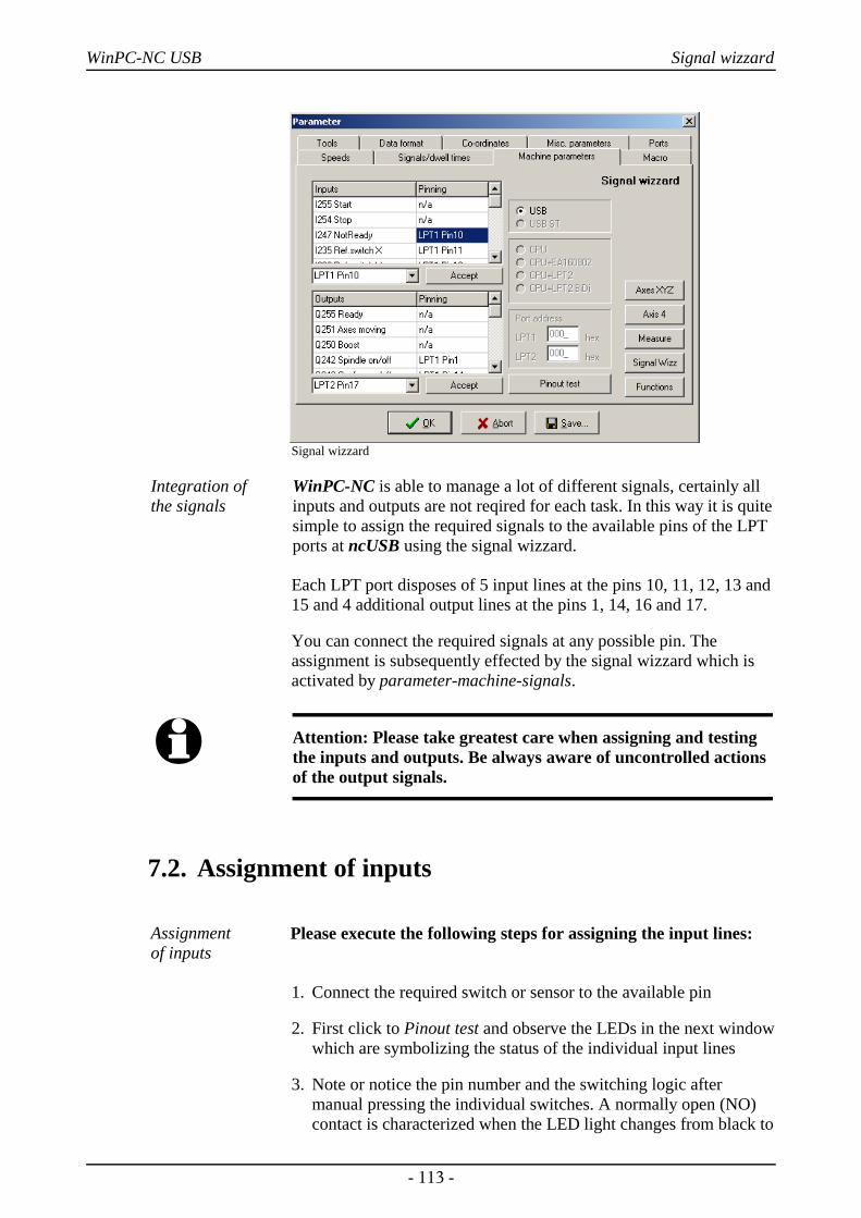
WinPC-NC USB Signal wizzard
Signal wizzard
Integration of the signals
WinPC-NC is able to manage a lot of different signals, certainly allinputs and outputs are not reqired for each task. In this way it is quitesimple to assign the required signals to the available pins of the LPTports at ncUSB using the signal wizzard.
Each LPT port disposes of 5 input lines at the pins 10, 11, 12, 13 and15 and 4 additional output lines at the pins 1, 14, 16 and 17.
You can connect the required signals at any possible pin. Theassignment is subsequently effected by the signal wizzard which isactivated by parameter-machine-signals.
i Attention: Please take greatest care when assigning and testingthe inputs and outputs. Be always aware of uncontrolled actionsof the output signals.
7.2. Assignment of inputs
Assignment of inputs
Please execute the following steps for assigning the input lines:
1. Connect the required switch or sensor to the available pin
2. First click to Pinout test and observe the LEDs in the next windowwhich are symbolizing the status of the individual input lines
3. Note or notice the pin number and the switching logic aftermanual pressing the individual switches. A normally open (NO)contact is characterized when the LED light changes from black to
- 113 -
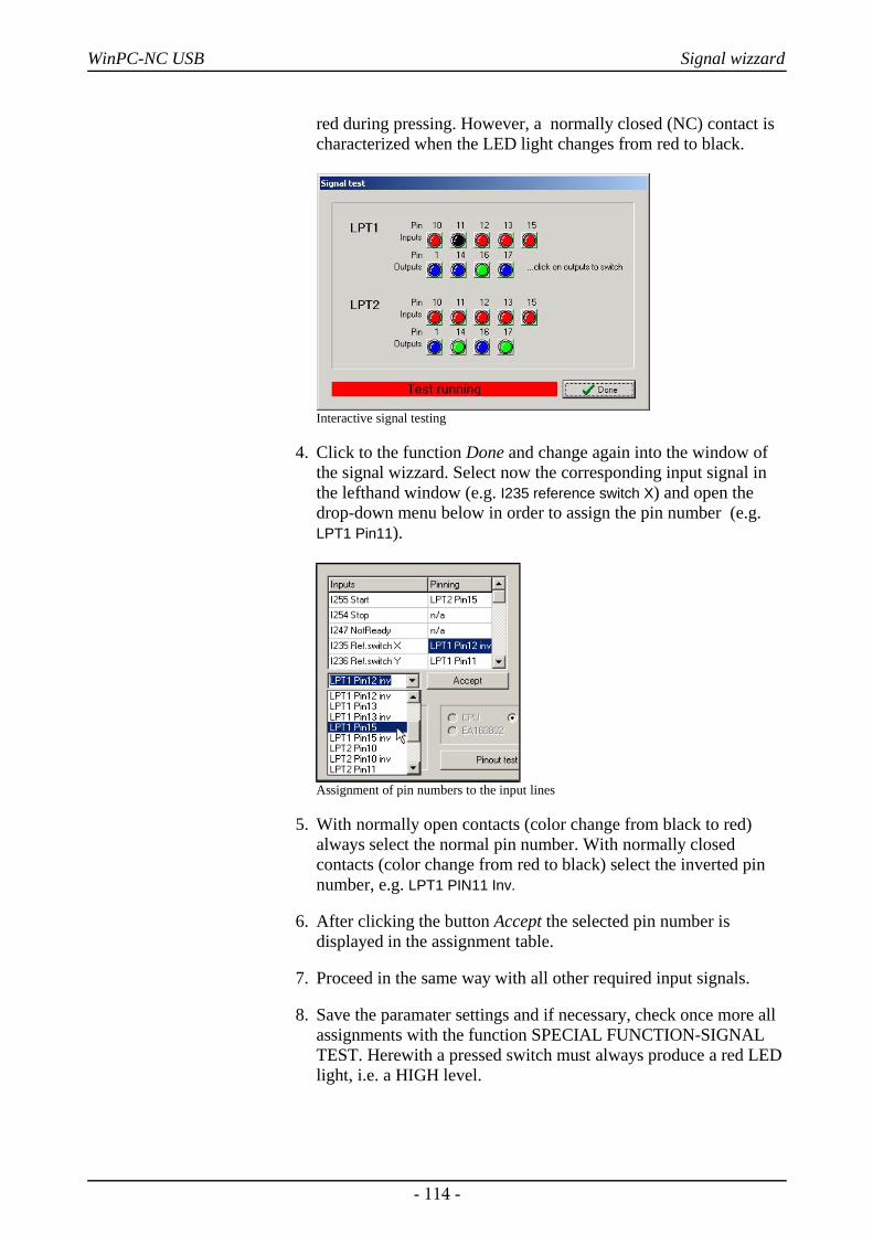
WinPC-NC USB Signal wizzard
red during pressing. However, a normally closed (NC) contact ischaracterized when the LED light changes from red to black.
Interactive signal testing
4. Click to the function Done and change again into the window ofthe signal wizzard. Select now the corresponding input signal inthe lefthand window (e.g. I235 reference switch X) and open thedrop-down menu below in order to assign the pin number (e.g.LPT1 Pin11).
Assignment of pin numbers to the input lines
5. With normally open contacts (color change from black to red)always select the normal pin number. With normally closedcontacts (color change from red to black) select the inverted pinnumber, e.g. LPT1 PIN11 Inv.
6. After clicking the button Accept the selected pin number isdisplayed in the assignment table.
7. Proceed in the same way with all other required input signals.
8. Save the paramater settings and if necessary, check once more allassignments with the function SPECIAL FUNCTION-SIGNALTEST. Herewith a pressed switch must always produce a red LEDlight, i.e. a HIGH level.
- 114 -
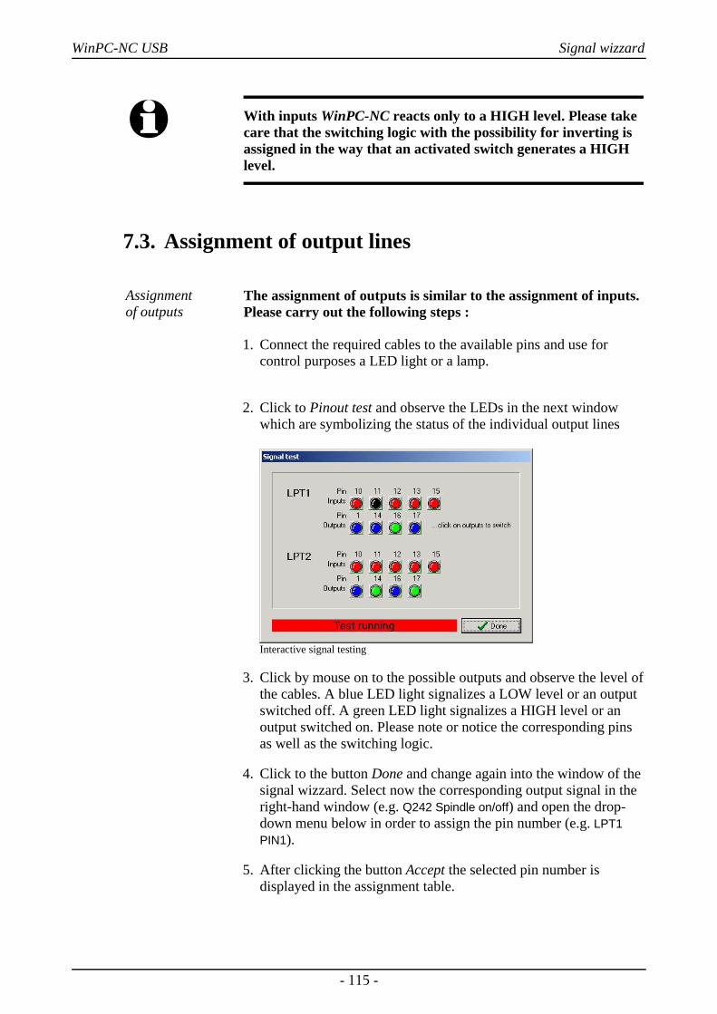
WinPC-NC USB Signal wizzard
i With inputs WinPC-NC reacts only to a HIGH level. Please takecare that the switching logic with the possibility for inverting isassigned in the way that an activated switch generates a HIGHlevel.
7.3. Assignment of output lines
Assignment of outputs
The assignment of outputs is similar to the assignment of inputs.Please carry out the following steps :
1. Connect the required cables to the available pins and use forcontrol purposes a LED light or a lamp.
2. Click to Pinout test and observe the LEDs in the next windowwhich are symbolizing the status of the individual output lines
Interactive signal testing
3. Click by mouse on to the possible outputs and observe the level ofthe cables. A blue LED light signalizes a LOW level or an outputswitched off. A green LED light signalizes a HIGH level or anoutput switched on. Please note or notice the corresponding pinsas well as the switching logic.
4. Click to the button Done and change again into the window of thesignal wizzard. Select now the corresponding output signal in theright-hand window (e.g. Q242 Spindle on/off) and open the drop-down menu below in order to assign the pin number (e.g. LPT1PIN1).
5. After clicking the button Accept the selected pin number isdisplayed in the assignment table.
- 115 -
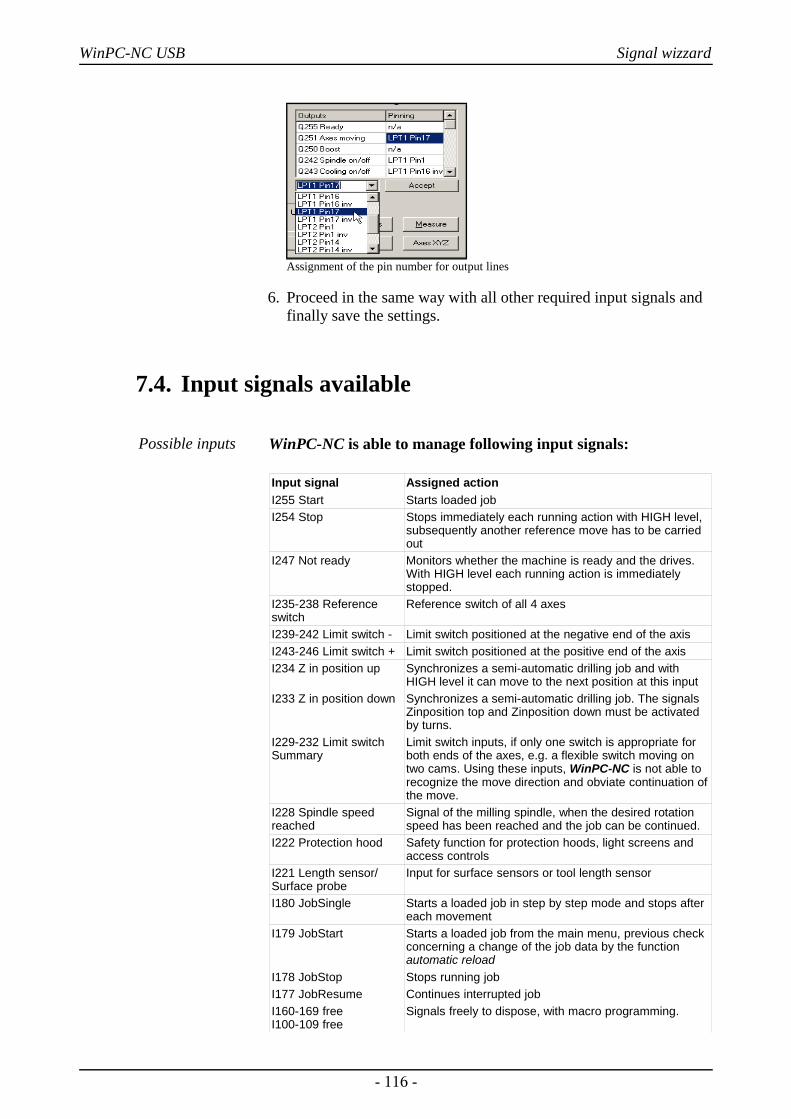
WinPC-NC USB Signal wizzard
Assignment of the pin number for output lines
6. Proceed in the same way with all other required input signals andfinally save the settings.
7.4. Input signals available
Possible inputs WinPC-NC is able to manage following input signals:
Input signal Assigned actionI255 Start Starts loaded jobI254 Stop Stops immediately each running action with HIGH level,
subsequently another reference move has to be carriedout
I247 Not ready Monitors whether the machine is ready and the drives.With HIGH level each running action is immediatelystopped.
I235-238 Referenceswitch
Reference switch of all 4 axes
I239-242 Limit switch - Limit switch positioned at the negative end of the axisI243-246 Limit switch + Limit switch positioned at the positive end of the axisI234 Z in position up Synchronizes a semi-automatic drilling job and with
HIGH level it can move to the next position at this inputI233 Z in position down Synchronizes a semi-automatic drilling job. The signals
Zinposition top and Zinposition down must be activatedby turns.
I229-232 Limit switchSummary
Limit switch inputs, if only one switch is appropriate forboth ends of the axes, e.g. a flexible switch moving ontwo cams. Using these inputs, WinPC-NC is not able torecognize the move direction and obviate continuation ofthe move.
I228 Spindle speedreached
Signal of the milling spindle, when the desired rotationspeed has been reached and the job can be continued.
I222 Protection hood Safety function for protection hoods, light screens andaccess controls
I221 Length sensor/Surface probe
Input for surface sensors or tool length sensor
I180 JobSingle Starts a loaded job in step by step mode and stops aftereach movement
I179 JobStart Starts a loaded job from the main menu, previous checkconcerning a change of the job data by the functionautomatic reload
I178 JobStop Stops running jobI177 JobResume Continues interrupted jobI160-169 freeI100-109 free
Signals freely to dispose, with macro programming.
- 116 -
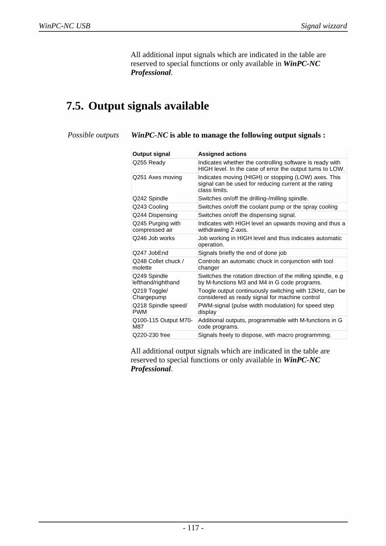
WinPC-NC USB Signal wizzard
All additional input signals which are indicated in the table arereserved to special functions or only available in WinPC-NCProfessional.
7.5. Output signals available
Possible outputs WinPC-NC is able to manage the following output signals :
Output signal Assigned actionsQ255 Ready Indicates whether the controlling software is ready with
HIGH level. In the case of error the output turns to LOW.Q251 Axes moving Indicates moving (HIGH) or stopping (LOW) axes. This
signal can be used for reducing current at the ratingclass limits.
Q242 Spindle Switches on/off the drilling-/milling spindle.Q243 Cooling Switches on/off the coolant pump or the spray coolingQ244 Dispensing Switches on/off the dispensing signal.Q245 Purging withcompressed air
Indicates with HIGH level an upwards moving and thus awithdrawing Z-axis.
Q246 Job works Job working in HIGH level and thus indicates automaticoperation.
Q247 JobEnd Signals briefly the end of done jobQ248 Collet chuck /molette
Controls an automatic chuck in conjunction with toolchanger
Q249 Spindlelefthand/righthand
Switches the rotation direction of the milling spindle, e.gby M-functions M3 and M4 in G code programs.
Q219 Toggle/Chargepump
Toogle output continuously switching with 12kHz, can beconsidered as ready signal for machine control
Q218 Spindle speed/PWM
PWM-signal (pulse width modulation) for speed stepdisplay
Q100-115 Output M70-M87
Additional outputs, programmable with M-functions in Gcode programs.
Q220-230 free Signals freely to dispose, with macro programming.
All additional output signals which are indicated in the table arereserved to special functions or only available in WinPC-NCProfessional.
- 117 -
WinPC-NC USB Additional Information
8. Additional Information
8.1. InterpretersAt present, interpreters are implemented in WinPC-NC USB forserveral NC data formats.
• HPGL• Drilling data• Multicam• G code (DIN/ISO)• ISEL NCP• Postscript (vector information in EPS and AI files)• DXF (2D)
8.1.1. HPGL-Interpreter
Plotter data with the HPGLInterpreter
The HPGL interpreter recognizes the most important commands inHPGL plotter language. Successful tests have been carried out withvarious CAD and drawing programs.
Drawings from...
• AutoCAD®
• AutoSketch®
• Eagle®
• HCAM®
• CADdy®
Windows HPGLdrivers
...and other CAD systems can be processed without any problems.Furthermore, the interpreter can also work with HPGL data from thestandard Window driver HP-Plotter, which programs such as...
• CorelDRAW®
• Designer®
...and other Windows drawing programs use for preparing their dataand storing data in a file. Alternatively, it is also possible to use adriver for following plotters: HP7475, HP Color Pro or HPDraftmaster.
- 118 -
WinPC-NC USB Additional Information
HPGL Syntax The following commands represent a valid HPGL data file :
PA [x,y[,x,y]]; Move to absolute position(s)PR [x,y[,x,y]]; Move to relative position(s)PU [x,y[,x,y]]; Lift and move toolPD [x,y[,x,y]]; Lower and move toolSP x; Select toolIP x,y,[,x,y]; Define scaling pointsSC x,y,x,y; Define scaling factorsCI r[,a]; Draw complete circleAA x,y,a[,c]; Absolute arcAR x,y,a[,c]; Relative arc
In addition, the interpreter recognizes the following commandsalthough no response is produced on the machine :
DT...; LT...;LB...; VS...;IN...; CA...;
The following non-standard expansions can also be used :
PP; Drill hole, lower/lift toolFCt; Wait t millisecondsFC100,t; Wait t millisecondsFC101,i; Wait for HIGH level at input iFC102,i; Wait for LOW level at input iFC200,a; Set output a to HIGHFC201,a; Set output a to LOWFC300,m; Activates a programmable macro m
HPGL language prescribes the following syntactical rules, amongstothers, which must be observed when creating or revising the data.
• There must always be a pair of coordinates x,y • All commands with coordinates must have no, one or more
coordinate pairs • Every command must be followed by a semicolon (;) or a new
command• With PA and PR, the subsequent commands are also set to
absolute or relative positioning• The last command should lift the tool (PU;)
HPGL example PU;PA1000,1000;SP1;PD;PA1000,2000;PA2000,2000;PA2000,1000;PA1000,1000;PU;
Start by lifting toolThen move to 1000/1000 Select tool 1Lower toolMove square
Lift tool
- 119 -
WinPC-NC USB Additional Information
8.1.2. MultiCAM-Interpreter
HPGL extended with 3D commands
The MultiCAM format is a 3D expansion of the HPGL standard. Itincludes all previous HPGL commands and some additional ones bymeans of which the Z-axis can be moved synchronously with theother axes.
A differentiation is made between 2D and 3D modes. There mustalways be 3 coordinates in 3D mode, i.e. one for the Z-axis as well.
ZZ0/1; Activates 2D or 3D modeZUz; Toollift height of the Z-axis over the zero point
(overwrites the safety clearance parameter)ZDz; Plunge depth (overwrites the depth values in the
parameters)SFv; Feed rateZOd; Spindle speed
The syntactical rules of HPGL language apply analogously toMultiCAM.
8.1.3. Drilling data interpreter
Various drillingdata formats
The drilling data interpreter recognizes data in the followingstandards Excellon, Sieb&Maier1000 and Sieb&Maier3000.
A drilling file always starts with one or two percent signs and endswith the command M30. In between, there can be any number oflines with X and Y coordinates and the tool number.
Drilling datasntax
The syntax is as follows:
% oder %%[Xval][Yval][Tx].....M30
There are two different formats. In format 1, the coordinate valuesare always 5-digit numbers, although it is possible to leave off thetrailing zeros (e.g. X021 corresponds to 2100).
In format 2, leading zeros are discarded and the coordinate valuestherefore comprise different numbers of digits.
The drilling formats prescribe the following syntactical rules,amongst others, which must be observed when creating or revisingthe data.
- 120 -
WinPC-NC USB Additional Information
• Every command must be in its own line• If coordinates and a tool command are contained in the same line,
then the tool is changed first before drilling takes place at the position
• The coordinates can also include a decimal point, e.g. X123.456 • All lines before the percent sign(s) are regarded as remarks and
are skipped
Sample of drillingdata in format 2
Short drilling program informat 2%T1X1000Y1000X1200Y2340X2700Y2950T2Y1000M30
Remark lines
Start of programSelect tool 1Drill hole at 1000/1000Drill hole at 1200/2340Tool 2 drill hole at 2700/2950Drill hole at 2700/1000End of program
And here is the same example in format 1: (always 5-digit values,with trailing zeros discarded)
Sample of drillingdata in format 1
Short drilling program informat 1%T1X01Y01 X012Y0234X027Y0295T2Y01M30
Remark lines
Start of programSelect tool 1Drill hole at 1000/1000Drill hole at 1200/2340Tool 2 drill hole at 2700/2950Drill hole at 2700/1000End of program
8.1.4. G code interpreterWinPC-NC also contains a small G code command interpreter. TheG code language is used in professional and industrial applicationsfor programming NC machines.
The following commands are supported :
G commands G00 Linear interpolation with rapid speedG01 Machining, linear interpolationG02 Clockwise circular movementG03 Counterclockwise circular movement G04 Dwell time, time with F command G17 Plane XYG18 Plane XZG19 Plane YZG54..59 Shift of zero point G70 Dimensions in inchG71 Dimensions in mm
- 121 -
WinPC-NC USB Additional Information
G81 Drilling and withdrawal in slow speedZ-depth R-toollift P-dwell time
G82 Drilling and withdrawal in rapid speedZ-depth R-toollift P-dwell time
G90 Absolute position informationG91 Relative position informationG98 Define subroutines
M commands M00 Program haltM02 End of programM03 Spindle on, clockwise rotationM04 Spindle on, counterclockwise rotationM05 Spindle offM06 Change toolM07 Coolant onM08 Coolant onM09 Coolant offM16 Wait for input, input number in FM30 End of programM66 Change tool, same as M06M70..77 Set output 100..107 to HIGHM-70..-77 Set output 100..107 to LOWM80..87 Set output 108..115 to HIGHM-80..-87 Set output 108..115 to LOWM90..99 activate programmable macros 1..10M106 set output HIGH for 3D printer headM107 set output LOW for 3D printer head
Other N Record numberS Spindle speedF Pin number (with M16 command)F Dwell time (with G04 command)F Feed (without M16 and G04 command)
Speed in set unit of measurement (mm/s ormm/min. or inch/min.)
I,J,K Circle parametersT Select toolX,Y,Z CoordinatesU,V,W Coordinates for 4th axis, if activatedA,B,C Coordinates for 4th axis, if activatedR Radius of arcsR toollift for G81/82 drillingP dwell time at G81/82 drillingL Call subroutines (1..20)
- 122 -
WinPC-NC USB Additional Information
Example: Squarewith roundedcorners
%prog2N001 G90N002 G71 T1 M6N003 G00 X110 Y100 Z10N004 G01 Z11N005 G01 X190N006 G03 X200 Y110 J10N007 G01 Y190N008 G03 X190 Y200 I-10N009 G01 X110N010 G03 X100 Y190 J-10N011 G01 Y110N012 G03 X110 Y100 I10N013 G01 Z10N014 G00 X0 Y0 Z0N015 M30
Start of program Absolute coordinatesDimensions in mm, tool 1Speed to 1st positionPlunge movement with ZFeed movement in straight lineArc about center pointetc...
Rapid speed to zero pointEnd of program
Bear in mind the following points when writing G code programs :
• The programs must be written using an editor or an external program
• The program name with % sign introduces the real program code,all preceding lines are remark lines
• At least one tool has to be selected and changed, e.g. with T1 M6 in the program head (M6 is absolutely necessary)
• Speeds are adjustable with F commands in mm/sec. or mm/min. defined by paramaters.
• The command number can be defined using N commands • For arcs, you can either use the I, J, K commands to define the
center point or R to program a radius. Positive radii produce an arc less than 180° and negative radii an arc greater than 180°.
• Up to 20 subroutines are defined at the end of the main program after M30, using G98 Lx. The definition ends with G98 L0. The subroutine call can be positioned anywhere with Lx.
• In the course of the zero shift with G54ff the definition of the zero point is made by the call line G54Xxxx Yyy by defining the relative offset to the current zero point by the coordinate values. Activating the zero point is then made by the only command G54without coordinates.
- 123 -
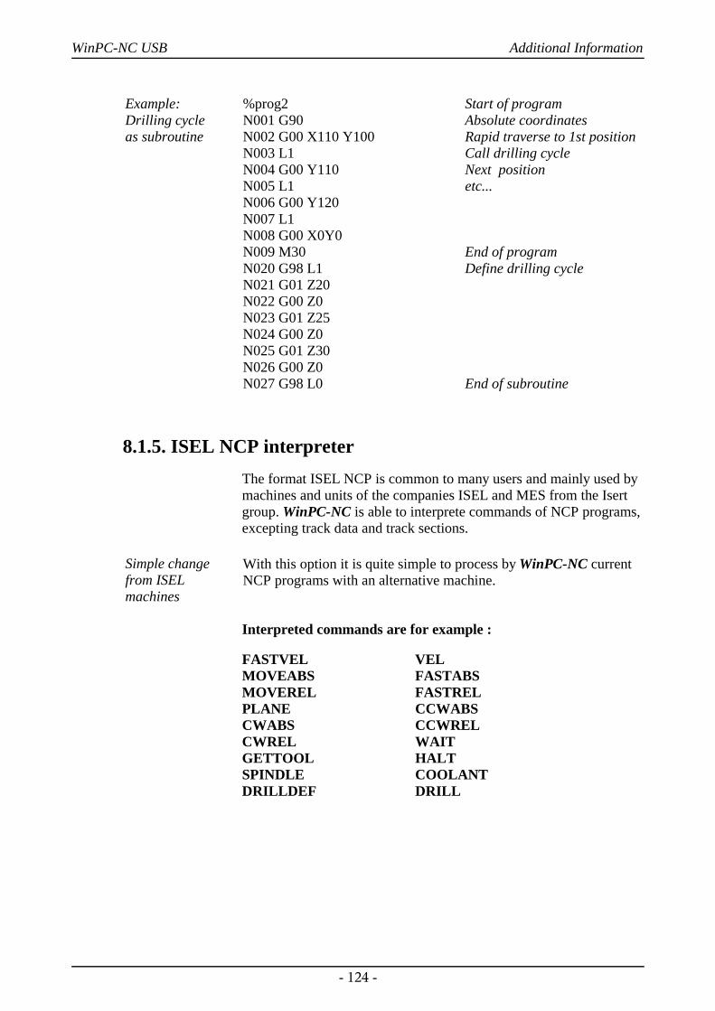
WinPC-NC USB Additional Information
Example: Drilling cycle as subroutine
%prog2N001 G90N002 G00 X110 Y100N003 L1N004 G00 Y110N005 L1N006 G00 Y120N007 L1N008 G00 X0Y0N009 M30N020 G98 L1N021 G01 Z20N022 G00 Z0N023 G01 Z25N024 G00 Z0N025 G01 Z30N026 G00 Z0N027 G98 L0
Start of programAbsolute coordinatesRapid traverse to 1st positionCall drilling cycleNext positionetc...
End of programDefine drilling cycle
End of subroutine
8.1.5. ISEL NCP interpreterThe format ISEL NCP is common to many users and mainly used bymachines and units of the companies ISEL and MES from the Isertgroup. WinPC-NC is able to interprete commands of NCP programs,excepting track data and track sections.
Simple changefrom ISELmachines
With this option it is quite simple to process by WinPC-NC currentNCP programs with an alternative machine.
Interpreted commands are for example :
FASTVEL VELMOVEABS FASTABSMOVEREL FASTRELPLANE CCWABSCWABS CCWRELCWREL WAITGETTOOL HALTSPINDLE COOLANTDRILLDEF DRILL
- 124 -
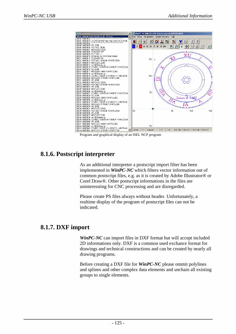
WinPC-NC USB Additional Information
Program and graphical display of an ISEL NCP program
8.1.6. Postscript interpreterAs an additional interpreter a postscript import filter has beenimplemented in WinPC-NC which filters vector information out ofcommon postscript files, e.g. as it is created by Adobe Illustrator® orCorel Draw®. Other postscript informations in the files areuninteressting for CNC processing and are disregarded.
Please create PS files always without header. Unfortunately, arealtime display of the program of postscript files can not beindicated.
8.1.7. DXF importWinPC-NC can import files in DXF format but will accept included2D informations only. DXF is a common used exchance format fordrawings and technical constructions and can be created by nearly alldrawing programs.
Before creating a DXF file for WinPC-NC please ommit polylinesand splines and other complex data elements and unchain all existinggroups to single elements.
- 125 -
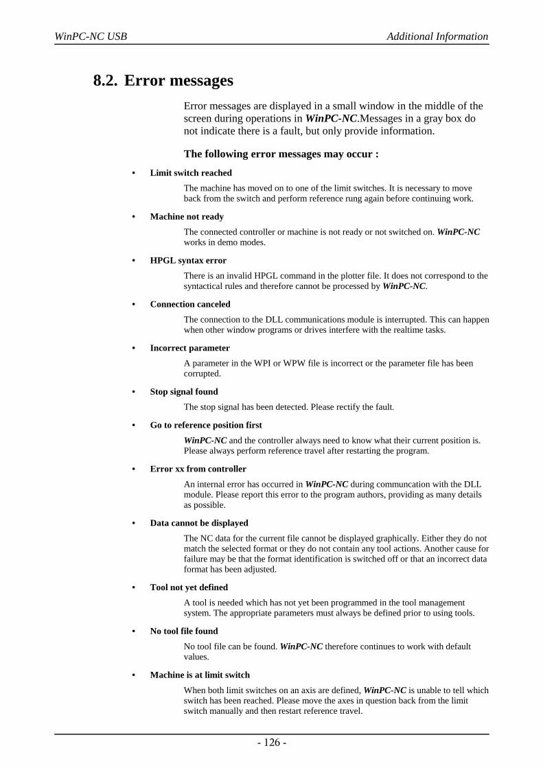
WinPC-NC USB Additional Information
8.2. Error messagesError messages are displayed in a small window in the middle of thescreen during operations in WinPC-NC.Messages in a gray box donot indicate there is a fault, but only provide information.
The following error messages may occur :
• Limit switch reached
The machine has moved on to one of the limit switches. It is necessary to moveback from the switch and perform reference rung again before continuing work.
• Machine not ready
The connected controller or machine is not ready or not switched on. WinPC-NCworks in demo modes.
• HPGL syntax error
There is an invalid HPGL command in the plotter file. It does not correspond to thesyntactical rules and therefore cannot be processed by WinPC-NC.
• Connection canceled
The connection to the DLL communications module is interrupted. This can happenwhen other window programs or drives interfere with the realtime tasks.
• Incorrect parameter
A parameter in the WPI or WPW file is incorrect or the parameter file has beencorrupted.
• Stop signal found
The stop signal has been detected. Please rectify the fault.
• Go to reference position first
WinPC-NC and the controller always need to know what their current position is.Please always perform reference travel after restarting the program.
• Error xx from controller
An internal error has occurred in WinPC-NC during communcation with the DLLmodule. Please report this error to the program authors, providing as many detailsas possible.
• Data cannot be displayed
The NC data for the current file cannot be displayed graphically. Either they do notmatch the selected format or they do not contain any tool actions. Another cause forfailure may be that the format identification is switched off or that an incorrect dataformat has been adjusted.
• Tool not yet defined
A tool is needed which has not yet been programmed in the tool managementsystem. The appropriate parameters must always be defined prior to using tools.
• No tool file found
No tool file can be found. WinPC-NC therefore continues to work with defaultvalues.
• Machine is at limit switch
When both limit switches on an axis are defined, WinPC-NC is unable to tell whichswitch has been reached. Please move the axes in question back from the limitswitch manually and then restart reference travel.
- 126 -
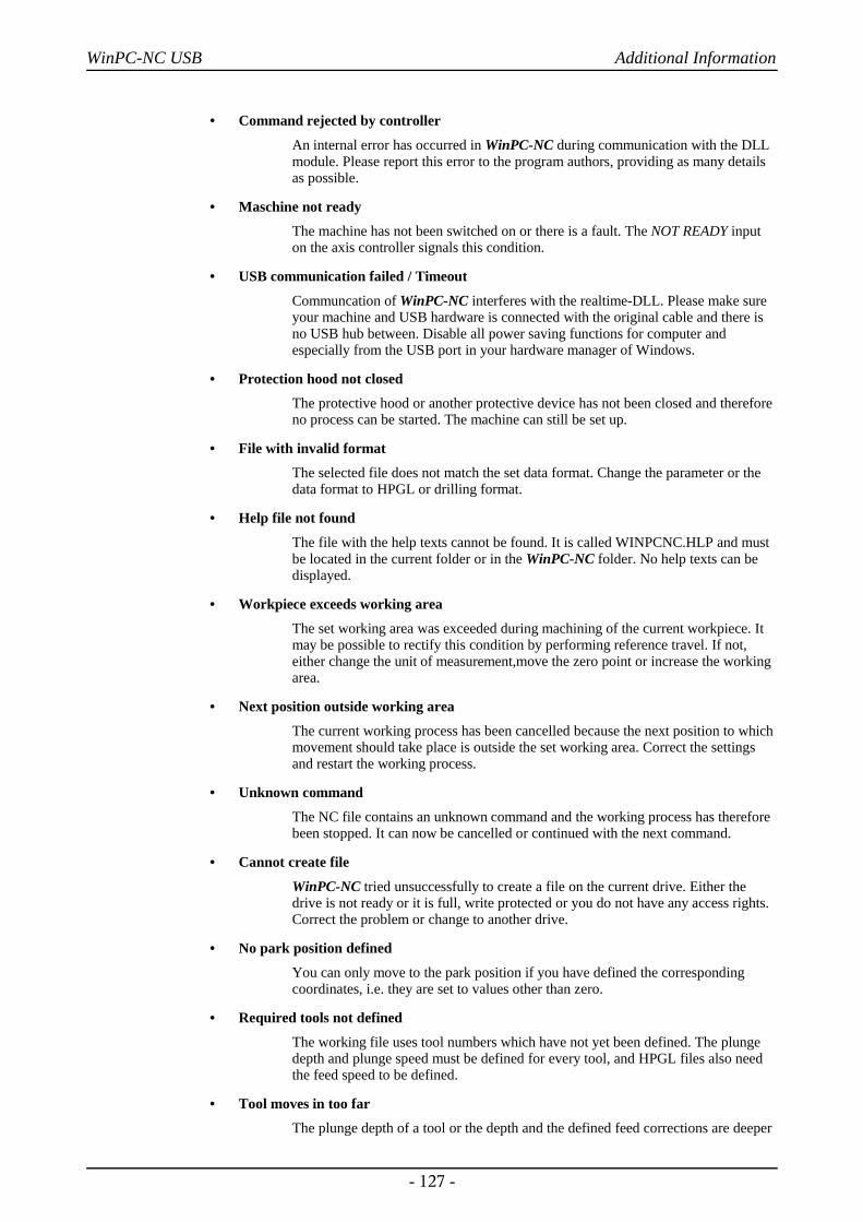
WinPC-NC USB Additional Information
• Command rejected by controller
An internal error has occurred in WinPC-NC during communication with the DLLmodule. Please report this error to the program authors, providing as many detailsas possible.
• Maschine not ready
The machine has not been switched on or there is a fault. The NOT READY inputon the axis controller signals this condition.
• USB communication failed / Timeout
Communcation of WinPC-NC interferes with the realtime-DLL. Please make sureyour machine and USB hardware is connected with the original cable and there isno USB hub between. Disable all power saving functions for computer andespecially from the USB port in your hardware manager of Windows.
• Protection hood not closed
The protective hood or another protective device has not been closed and thereforeno process can be started. The machine can still be set up.
• File with invalid format
The selected file does not match the set data format. Change the parameter or thedata format to HPGL or drilling format.
• Help file not found
The file with the help texts cannot be found. It is called WINPCNC.HLP and mustbe located in the current folder or in the WinPC-NC folder. No help texts can bedisplayed.
• Workpiece exceeds working area
The set working area was exceeded during machining of the current workpiece. Itmay be possible to rectify this condition by performing reference travel. If not,either change the unit of measurement,move the zero point or increase the workingarea.
• Next position outside working area
The current working process has been cancelled because the next position to whichmovement should take place is outside the set working area. Correct the settingsand restart the working process.
• Unknown command
The NC file contains an unknown command and the working process has thereforebeen stopped. It can now be cancelled or continued with the next command.
• Cannot create file
WinPC-NC tried unsuccessfully to create a file on the current drive. Either thedrive is not ready or it is full, write protected or you do not have any access rights.Correct the problem or change to another drive.
• No park position defined
You can only move to the park position if you have defined the correspondingcoordinates, i.e. they are set to values other than zero.
• Required tools not defined
The working file uses tool numbers which have not yet been defined. The plungedepth and plunge speed must be defined for every tool, and HPGL files also needthe feed speed to be defined.
• Tool moves in too far
The plunge depth of a tool or the depth and the defined feed corrections are deeper
- 127 -
WinPC-NC USB Additional Information
than the maximum plunge depth or the limit of the Z-axis working area.
• G code or DIN/ISO syntax error
There is a syntactical error in the G code file being processed. Please use the editorto correct the line in question and restart the working process.
• Maschine positioned on the reference switch
You intend to execute a reference move, however there is at least one axis alreadypositioned on the reference switch. Start moving back all axes from the switches bymanual operation.
• Cannot create file
WinPC-NC tried unsuccessfully to install a file. Possibible causes are insufficientmemory capacity or missing allowance for access in the current register.
• Out of memory
There is insufficient vacant main memory space for processing actions by WinPC-NC. Please extend the virtual memory in the system control and restart WinPC-NC.
• Incorrect realtime-DLL
There are communcation problems between the actual realtime module andWinPC-NC which are probably caused by another licence.
• DIN-syntax error / DIN-circular arc error
There is an incorrect command in the indicated line of the DIN/ISO file or theprogramed circular arc does not match the indicated center point.
• Error in speed
The defined speed does not match the corresponding machine parameters.
8.3. Special versions of WinPC-NC
Specialapplications on request
The authors are always grateful for opinions and suggestions.
If required, hardware and software solutions can be worked out foryour special application, or our standard products can be adapted tooptimize their functions for you. Please ask us for a quote withoutobligation.
We have taken great efforts already in the past to provide anoptimum of solutions concerning special functions and options. As aresult we have launched successfully our professional version, calledWinPC-NC Professional. This application is absolutely qualified forindividual operation purposes and for controlling specific accessorycomponents.
Here are some examples:
• Dispensing plants for glass inserts and reconstructed motif glasses
• Laser welding plants and laser marking devices
- 128 -

WinPC-NC USB Additional Information
• Plasma cutting plants and oxy cutters
• Laboratory applications for complex measuring tasks
• Machines using double heads and double Z axes for two tools
• and there are many other applications besides
In conjunction with the axes controller of Win-PC-NC Professionalyou have also the possibility for direct control out of externalprograms. The communication report of the axes controller iscarefully documented and can be provided on request. Thus the useris able to apply any other host systems independent of the WinPC-NC user interface.
- 129 -
Related Documents