This work has been submitted to NECTAR, the Northampton Electronic Collection of Theses and Research. Thesis Title: WiMAX-WiFi techniques for baseband convergence and routing protocols Creator: Al-Sherbaz, A. Example citation: Al-Sherbaz, A. (2010) WiMAX-WiFi techniques for baseband convergence and routing protocols. Doctoral thesis. The University of Buckingham. Version: Accepted version http://nectar.northampton.ac.uk/4241/ NECTAR

Welcome message from author
This document is posted to help you gain knowledge. Please leave a comment to let me know what you think about it! Share it to your friends and learn new things together.
Transcript
This work has been submitted to NECTAR, the Northampton ElectronicCollection of Theses and Research.
Thesis
Title: WiMAX-WiFi techniques for baseband convergence and routing protocols
Creator: Al-Sherbaz, A.
Example citation: Al-Sherbaz, A. (2010) WiMAX-WiFi techniques for basebandconvergence and routing protocols. Doctoral thesis. The University ofBuckingham.
Version: Accepted version
http://nectar.northampton.ac.uk/4241/
NECTAR
WIMAX-WIFI TECHNIQUES FOR BASEBAND
CONVERGENCE AND ROUTING PROTOCOLS
BY
ALI AL-SHERBAZ
APPLIED COMPUTING DEPARTMENT
A THESIS SUBMITTED FOR THE DEGREE OF
DOCTOR OF PHILOSOPHY IN COMPUTER SCIENCE
TO THE SCHOOL OF SCIENCE IN THE UNIVERSITY OF BUCKINGHAM
AUGUST 2010
II
Abstract
The focus of this study was to investigate solutions that, when implemented in any
heterogeneous wireless network, shall enhance the existing standard and routing
protocol connectivity without impacting the standard or changing the wireless
transceiver’s functions. Thus achieving efficient interoperability at much reduced
overheads. The techniques proposed in this research are centred on the lower
layers. This because of the facts that WiMax and WiFi standards have not addressed
the backward compatibility of the two technologies at the MAC and PHY layers, for
both the baseband functions as well as the routing IP addresses. This thesis
describes two innovate techniques submitted for a PhD degree.
The first technique is to combine WiMax and WiFi signals so to utilise the same
"baseband implementation chain" to handle both of these technologies, thus
insuring ubiquitous data communication. WiMax-WiFi Baseband Convergence
(W2BC) implementation is proposed to offer an optimum configurable solution
targeted at combining the 802.16d WiMax and the 802.11a WiFi technologies. This
approach provides a fertile ground for future work into combining more OFDM
based wireless technologies. Based on analysis and simulation, the W2BC can
achieve saving in device cost, size, power consumption and implementation
complexity when compared to current side-by-side implementations for these two
technologies.
The second technique, called "Prime-IP", can be implemented with, and enhance,
any routing protocol. During the route discovery process, Prime-IP enables any
node on a wireless mesh network (WMN) to dynamically select the best available
route on the network. Prime-IP proposes a novel recursive process, based on prime
numbers addressing, to accumulate knowledge for nodes beyond the “neighbouring
nodes”, and to determine the sequence of all the “intermediate nodes” used to form
the route.
III
Acknowledgments
I would like to thank God Almighty, who created the opportunity for me to have my
Dream,
I would like to bow in thanks to Dr. Habib Al-Sherbaz and Mrs Awaz Jiawook
(My Parents), who helped me to have my
Dream,
And to my love, my sweet heart, who continues to support me to live my
Dream,
I wish to thank my supervisors, Prof. Chris Adams and Dr. Ihsan Alshahib-Lami for
giving me the opportunity to conduct the research that I love, and for providing me
with the freedom and independence that have been essential to the making of this
thesis.
My sincere thanks to Prof. Sabah Jassim who got me started in my studies and who
helped me to finish them. Your feedback and constructive criticism has been a great
asset to me.
Many, many, thanks to my supervisor Dr. Naseer Al-Jawad for his assistance. You
were the person who puts his professional touches in the programming.
Sahar
IV
Abbreviations
FFT Fast Fourier Transform
IEEE Institute of Electrical and Electronics Engineers
IEEE 802.11 IEEE WiFi Standards
IEEE 802.16 IEEE WiMax Standards
MAC Media Access Control Layer
OFDM Orthogonal Frequency Division Multiplexing
PHY Physical Layer
RREP Route Reply Packet
RREQ Route Request Packet
W2BC WiMax-WiFi Baseband Convergence
WiFi Wireless Fidelity
WiMax World Interoperability for Microwave Access
WMN Wireless Mesh Networks
V
Table of Contents
ABSTRACT II
ACKNOWLEDGMENTS III
ABBREVIATIONS IV
LIST OF FIGURES VIII
LIST OF TABLES IX
DECLARATION X
CHAPTER 1: INTRODUCTION 1
1.1. MY RESEARCH MOTIVATION 2
1.2. MY RESEARCH PROGRESS 3
1.3. RESEARCH APPROACH/METHODOLOGY AND ACHIEVEMENTS 4
1.4. THESIS ORGANIZATION 6
CHAPTER 2: REVIEW OF WIMAX AND WIFI CONVERGENCE TECHNIQUES 8
2.1. REVIEW OF THE WIMAX AND WIFI TECHNOLOGIES 10
2.1.1. WiMax –WiFi Convergence Review 10
2.1.2. The WiFi IEEE 802.11 Standard Group 12
2.1.3. The WiMax IEEE 802.16 Standard Group 13
2.1.4. Historical Development of the OFDM Technology 14
2.2. REVIEW OF RELEVANT IEEE CONVERGENCE STANDARDS 15
2.2.1. The IEEE 802.11u- Internetworking with External Networks 16
2.2.2. The IEEE 802.16.4- WirelessHUMAN 16
2.2.3. The IEEE 802.21- Media Independent Handover 17
2.3. CURRENT WIMAX –WIFI CONVERGENCE APPROACHES 17
2.4. JUSTIFICATION OF THE W2BC WIRELESS CONVERGENCE 20
2.5. SUMMARY 22
CHAPTER 3: WIMAX-WIFI BASEBAND CONVERGENCE (W2BC) 23
3.1. WIFI-WIMAX SPECTRUM DESCRIPTION 24
3.1.1. WiFi-OFDM Signal 25
VI
3.1.2. WiMax-OFDM Signal 26
3.2. W2BC - MATHEMATICAL DESCRIPTION 28
3.3. SUMMARY 35
CHAPTER 4: W2BC SIMULATION AND RESULTS 36
4.1. W2BC SIMULATION MODEL DESCRIPTION 36
4.2. STATIC TESTS 38
4.2.1. WiMax Static Test 39
4.2.2. WiFi Static Test 40
4.3. DYNAMIC TESTS 41
4.3.1. Roaming between WiMax and WiFi Basestation Tests 43
4.3.2. Switching/Roaming between various WiMax Test 49
4.3.3. Switching between various WiFi Basestations Test 53
4.4. W2BC DISCUSSION AND CONCLUSION 56
CHAPTER 5: WMN ROUTING PROTOCOLS REVIEW 59
5.1. WMN ROUTING PROTOCOLS: EVALUATION CRITERIA 59
5.2. MANET WIRELESS NETWORK ROUTING PROTOCOLS (WITHOUT INFRASTRUCTURE) 62
5.2.1. Classification Based on the Routing Information Update Mechanism 63
5.2.2. Classification Based on the use of Temporal Information/Metrics for Routing
64
5.2.3. Classification based on Utilization of Specific Resources 64
5.2.4. Classification Based on the Routing Topology 65
5.3. ROUTING PROTOCOLS FOR WIRELESS MESH NETWORKS (WITH INFRASTRUCTURE) 66
5.3.1. Link Quality Source Routing (LQSR) 67
5.3.2. Extremely Opportunistic Routing (ExOR) 67
5.3.3. Multi-Channel Opportunistic Routing (MCExOR) 68
5.3.4. Multi-Channel Routing Protocol (MCRP) 68
5.3.5. Multi-Radio Link Quality Source Routing (MR-LQSR) 68
5.3.6. Multi-Channel Routing (MCR) 69
5.4. ROUTING ALGORITHMS IN WIFI-MESH (IEEE 802.11S) 70
5.4.1. Hybrid Wireless Mesh Protocol 70
VII
5.5. ROUTING ALGORITHMS IN WIMAX-MESH (IEEE 802.16) 72
5.5.1. Interference Aware Routing 74
5.5.2. Routing For Throughput Maximization 75
5.5.3. Other Routing Protocols 76
5.6. WIMAX-WIFI MESH CONVERGENCE ROUTING PROTOCOLS 77
5.7. WIRELESS ROUTING PROTOCOL IN IPV6 78
5.8. SUMMARY 80
CHAPTER 6: PRIME-IP ALGORITHM 81
6.1. THE OVERALL PROCESS 82
6.2. MATHEMATICAL DERIVATION 84
6.3. IPV4/IPV6 ADDRESSES 88
6.4. BACKTRACK PROCEDURE 90
6.5. BACKTRACK PROCEDURE - SCENARIO 1 95
6.6. BACKTRACK PROCEDURE – SCENARIO 2 102
6.7. PACKET SIZE 111
6.8. DELAY CALCULATIONS 112
6.9. SUMMARY: 112
CHAPTER 7: CONCLUSIONS AND FUTURE WORK 115
7.1. WHAT DOES W2BC DELIVERS? 115
7.2. WHAT DOES PRIME-IP DELIVERS? 116
7.3. A VISION FOR THE FUTURE 117
REFERENCES 119
VIII
List of Figures
FIGURE 1-1, THE PHD RESEARCH PROGRESS AND THE RELATED PUBLICATIONS 3
FIGURE 1-2, THESIS ORGANISATION 7
FIGURE 2-1 , WIMAX-WIFI SINGLE CHIP 19
FIGURE 3-2, WIMAX-OFDM-256 SPECTRUM THAT SHOWS THE SUB-CARRIER INDICES 27
FIGURE 3-3, WIMAX-OFDM, WIFI-OFDM SIGNALS (TIME AND FREQUENCY DOMAINS) 28
FIGURE 3-4, WIMAX - WIFI PHY LAYER BLOCK DIAGRAM 30
FIGURE 4-1, SIMULINK MODEL FOR THE W2BC 38
FIGURE 4-2, MATLAB RESULTS FOR W2BC STATIC TEST SHOWING 40
FIGURE 4-3, MATLAB RESULTS FOR W2BC STATIC TEST SHOWING 41
FIGURE 4-4, A BLOCK DIAGRAM OF THE TEST SETUP FOR THE 42
FIGURE 4-5, TEST THE W2BC SWITCHING TIME, THROUGH WIFI-WIMAX-WIFI SEQUENCE FOR DOWNLOADING A 65KBYTES DATA STREAM AT 15DB SNR 44
FIGURE 4-6, TEST THE W2BC SWITCHING TIME, THROUGH WIMAX AND WIFI, 45
FIGURE 4-7, SHOWING THE W2BC SWITCHING TIME AND BER, THROUGH WIMAX AND WIFI, FOR A 3KB DATA STREAM AT 5DB SNR 46
FIGURE 4-8, SHOWING THE W2BC SWITCHING TIME AND BER, THROUGH WIMAX AND WIFI, FOR A 3KB DATA STREAM AT 10DB SNR 47
FIGURE 4-9, SHOWING THE W2BC SWITCHING TIME AND BER, THROUGH WIMAX AND WIFI, FOR A 3KB DATA STREAM AT 15DB SNR 47
FIGURE 4-10, SHOWING THE W2BC SWITCHING TIME AND BER, THROUGH WIMAX AND WIFI, FOR A 3KB DATA STREAM AT 17DB SNR 48
FIGURE 4-11, SHOWING THE W2BC SWITCHING TIME AND BER, THROUGH WIMAX AND WIFI, FOR A 3KB DATA STREAM AT 20DB SNR 48
FIGURE 4-12, BER FOR SNR VALUES (5, 10, 15, 17 AND 20 DB) 49
FIGURE 4-13, SHOWING THE W2BC SWITCHING TIME AND BER, THROUGH WIMAX, FOR A 4.7KB DATA STREAM AT 5DB SNR 50
FIGURE 4-14, SHOWING THE W2BC SWITCHING TIME AND BER, THROUGH WIMAX, FOR A 4.7KB DATA STREAM AT 10DB SNR 50
FIGURE 4-15, SHOWING THE W2BC SWITCHING TIME AND BER, THROUGH WIMAX, FOR A 4.7KB DATA STREAM AT 15DB SNR 51
FIGURE 4-16, SHOWING THE W2BC SWITCHING TIME AND BER, THROUGH WIMAX, FOR A 4.7KB DATA STREAM AT 17DB SNR 51
FIGURE 4-17, SHOWING THE W2BC SWITCHING TIME AND BER, THROUGH WIMAX, FOR A 4.7KB DATA STREAM AT 20DB SNR 52
FIGURE 4-18, BER FOR SNR RANGE (5,10,15,17 AND 20 DB) IN WIMAX 52
FIGURE 4-19, SHOWING THE W2BC SWITCHING TIME AND BER, THROUGH WIFI, FOR A 1.2KB DATA STREAM AT 5DB SNR 53
FIGURE 4-20, SHOWING THE W2BC SWITCHING TIME AND BER, THROUGH WIFI, FOR A 1.2KB DATA STREAM AT 10DB SNR 54
FIGURE 4-21, SHOWING THE W2BC SWITCHING TIME AND BER, THROUGH WIFI, FOR A 1.2KB DATA STREAM AT 15DB SNR 54
FIGURE 4-22, SHOWING THE W2BC SWITCHING TIME AND BER, THROUGH WIFI, FOR A 1.2KB DATA STREAM AT 17DB SNR 55
FIGURE 4-23, SHOWING THE W2BC SWITCHING TIME AND BER, THROUGH WIFI, FOR A 1.2KB DATA STREAM AT 20DB SNR 55
FIGURE 4-24, BER VS. SNR RANGE (5, 10, 15, 17 AND 20 DB) IN WIFI 56
FIGURE 5-1, A TYPICAL MESH NETWORK 73
FIGURE 6-1, DIAGRAM OF A GENERAL WMN TOPOLOGY 83
FIGURE 6-2, GENERAL CLIENT WIRELESS MESH NETWORK TOPOLOGY OR MOBILE AD-HOC NETWORKS (MANET) 83
FIGURE 6-3, RANDOM WMN TOPOLOGY WITH A PRIME NUMBER ADDRESSES 85
FIGURE 6-4, IPV4 AND IPV6 ADDRESS FORMAT 88
FIGURE 6-5, ROUTE 1 NODE ADDRESSES 91
FIGURE 6-6, ROUTE 2 NODE ADDRESSES 91
FIGURE 6-7, ROUTE 3 NODE ADDRESSES 92
FIGURE 6-8, “BACKTRACK PROCEDURE” FOR ROUTE 3 92
FIGURE 6-9, FLOW CHART OF THE OVERALL BACKTRACK PROCEDURE 96
FIGURE 6-10, PSEUDO-CODE OF THE BOOKMARK SUB-PROCEDURE 97
FIGURE 6-11, PSEUDO-CODE OF THE FORWARD SUB-PROCEDURE 97
FIGURE 6-12, PSEUDO-CODE THE BACKWARD SUB-PROCEDURE 98
FIGURE 6-13, DIARGAM ILLUSTRTES THE MAX NUMBER OF INTERMEDIATE NODES IN WMN FOR USING PRIME-IP ALGORTHIM 111
IX
List of Tables
TABLE 2-1,WIMAX-WIFI CONVERGENCE COMPARISON 18
TABLE 3-1, WIFI/WIMAX SUBCARRIER INDICES 34
TABLE 4-1, COMMERCIAL WIMAX AND WIFI CHIPSETS 39
TABLE 4-2, CONFIGRATION PARAMENTS FOR THE 43
TABLE 4-3, ACTUAL IQ-MAP VALUES 43
TABLE 4-4, W2BC TESTS SUMMARY 57
TABLE 5-1, LIST OF WMN ROUTING PROTOCLS REVIEWED IN THIS STUDY 61
TABLE 6-1, PRIME NUMBERS REPRESENTATION IN THE IP ADDRESSES 89
TABLE 6-2, EXAMPLE OF CONSTRUCTING AND DECONSTRUCTING 94
TABLE 6-3 , EXAMPLE OF CONSTRUCTING AND DECONSTRUCTING OF THE 94
TABLE 6-4, EXAMPLE OF CONSTRUCTING AND DECONSTRUCTING OF THE 94
TABLE 6-5, MAX NUMBER OF INTERMEDIATE NODES FOR USING PRIME-IP 111

X
Declaration
I am hereby declare that all the work in this thesis is my own work ... and, to the
best of my knowledge, none of this materials has ever previously been submitted
for a degree in this or any other university.
1
Chapter 1: Introduction
This research work focuses on addressing the shortfalls identified in current
Wireless Mesh Networks (WMN). Multi standard interoperability and routing
protocols, as deployed in WiMax and WiFi networks, were carefully studied to
reduce overheads. This thesis proposes solutions, aimed at the lower layers of the
WiMax and WiFi technologies, to reduce not only the baseband implementation
overheads, but also enhancement to the most commonly used routing protocols. All
this improvements has been achieved without impacting these technologies
standards or these WMN protocols.
There have been many attempts to converge wireless transceivers functionality
and implementation at various layers (1), (2), (3), (4), (5). The first part of this
research was to explore the similarities of the OFDM signals, as used in WiMax and
WiFi, to converge their baseband implementation at the physical layer (PHY). This
attempt has resulted in a new convergence method by making these baseband
functions reconfigurable to serve WiMax or WiFi signals, thus reducing the
overheads of having side-by-side implementations of these two technologies. The
proposed WiMax-WiFi Baseband Convergence (W2BC) solution reduces
implementation complexity, size, power, and cost, while preserving signal and
communication integrity for standalone WiMax and WiFi functionality without
impacting the standards. W2BC is described in Chapter 3.
In their route discovery and selection process, current WMN protocols aims to
achieve minimum traffic processing overhead, higher security level, increased data
throughput, and reduced error rate (6). Proactive routing protocols achieve better
results for very small size networks. The overhead of accumulating knowledge for
all nodes in the network reduces the viability of using proactive protocols in favour
of the better connectivity but compromised reactive or on demand routing
protocols (7). The second part of this research, proposes Prime-IP, an algorithm
2
that enables optimum route path to be selected between the source and destination
nodes of a WMN. At the Media Access Control layer (MAC), Prime-IP deploys a
novel recursive process, based on prime numbers addressing, to accumulate
knowledge for nodes beyond the neighbouring nodes and to determine the
sequence of all the intermediate nodes used to form the route. Analysis and
simulations of typical dynamic topology of various WMNs proves that Prime-IP
functionality can be integrated with existing reactive routing protocols to gain the
added benefits of the proactive routing protocols as well, but with minimum
overhead. Prime-IP, patent pending, is described in Chapter 6.
1.1. My Research Motivation
The rapid change of wireless technologies development makes research in this field
very attractive and challenging. To engage in such research, it is important to
clearly understand and investigate the standards of the technologies and the
routing protocol, as well as constantly observe new amendments of the same.
Ever since I have completed my MSc degree in communications engineering, I was
passionate to work on Wireless stacks especially with the functions staged at the
lower layers (PHY and MAC layers). In 2006, I studied the WiMax technology and
how it offers the infrastructure solution for the last miles, something that my
country and other infrastructureless countries can benefit from. Furthermore,
when both WiMax and WiFi are integrated, a sufficient and affordable bandwidth
wireless networking can be developed to offer not only Internet services, but also
mobile TV and Multimedia applications. i.e. I envisaged that my research work with
these two technologies can help impact the future communication services due to
being easier to deploy and offering high bandwidth at lower cost when compared
with cellular technologies such as GSM and 3G.
I have chosen this research to help me understand the concepts of the WMN
infrastructure as deployed by using WiMax or WiFi, as well as how to design, plan,
3
integrate with other networks, configure routing protocols, and choose suitable
applications for such networks. I have thoroughly enjoyed this research experience.
1.2. My Research Progress
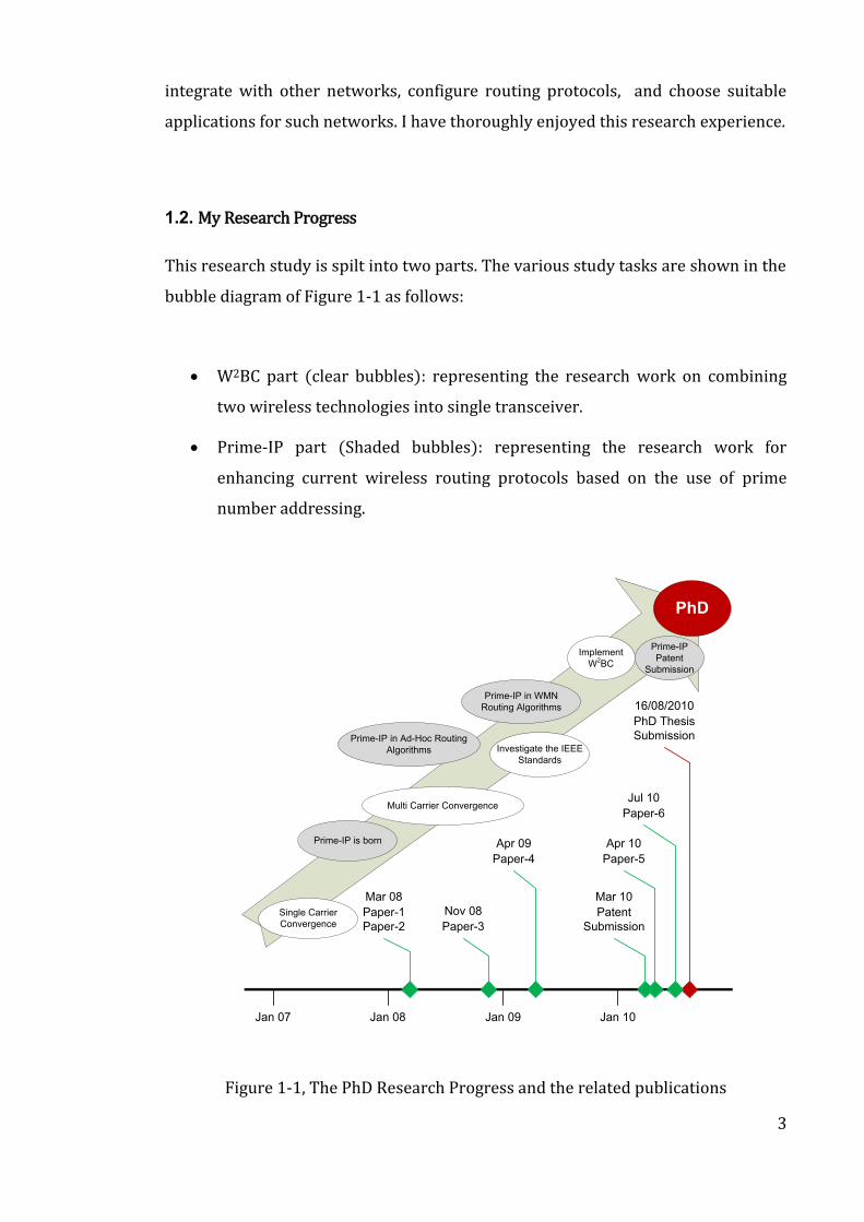
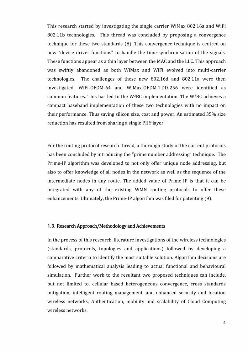
This research study is spilt into two parts. The various study tasks are shown in the
bubble diagram of Figure 1-1 as follows:
W2BC part (clear bubbles): representing the research work on combining
two wireless technologies into single transceiver.
Prime-IP part (Shaded bubbles): representing the research work for
enhancing current wireless routing protocols based on the use of prime
number addressing.
Single Carrier
Convergence
Multi Carrier Convergence
Investigate the IEEE
Standards
Implement
W2BC
PhD
Prime-IP is born
Prime-IP
Patent
Submission
Prime-IP in Ad-Hoc Routing
Algorithms
Prime-IP in WMN
Routing Algorithms
Jan 07 Jan 08 Jan 09 Jan 10
Apr 10
Paper-5
16/08/2010
PhD Thesis
Submission
Apr 09
Paper-4
Nov 08
Paper-3
Mar 08
Paper-1
Paper-2
Jul 10
Paper-6
Mar 10
Patent
Submission
Figure 1-1, The PhD Research Progress and the related publications
4
This research started by investigating the single carrier WiMax 802.16a and WiFi
802.11b technologies. This thread was concluded by proposing a convergence
technique for these two standards (8). This convergence technique is centred on
new “device driver functions” to handle the time-synchronisation of the signals.
These functions appear as a thin layer between the MAC and the LLC. This approach
was swiftly abandoned as both WiMax and WiFi evolved into multi-carrier
technologies. The challenges of these new 802.16d and 802.11a were then
investigated. WiFi-OFDM-64 and WiMax-OFDM-TDD-256 were identified as
common features. This has led to the W2BC implementation. The W2BC achieves a
compact baseband implementation of these two technologies with no impact on
their performance. Thus saving silicon size, cost and power. An estimated 35% size
reduction has resulted from sharing a single PHY layer.
For the routing protocol research thread, a thorough study of the current protocols
has been concluded by introducing the “prime number addressing” technique. The
Prime-IP algorithm was developed to not only offer unique node addressing, but
also to offer knowledge of all nodes in the network as well as the sequence of the
intermediate nodes in any route. The added value of Prime-IP is that it can be
integrated with any of the existing WMN routing protocols to offer these
enhancements. Ultimately, the Prime-IP algorithm was filed for patenting (9).
1.3. Research Approach/Methodology and Achievements
In the process of this research, literature investigations of the wireless technologies
(standards, protocols, topologies and applications) followed by developing a
comparative criteria to identify the most suitable solution. Algorithm decisions are
followed by mathematical analysis leading to actual functional and behavioural
simulation. Further work to the resultant two proposed techniques can include,
but not limited to, cellular based heterogeneous convergence, cross standards
mitigation, intelligent routing management, and enhanced security and location
wireless networks, Authentication, mobility and scalability of Cloud Computing
wireless networks.
5
Therefore, this 4-year research activity focused on the following:
To follow the standards: Investigate the possibilities and capabilities to
propose solutions without impacting the standards or the protocols. The
techniques have been altered to accommodate the latest amendments.
To keep touch with industry: this is to ensure that the research is
commercially viable. This has been achieved by joining industrial working
groups, publishing the work in known conferences/journals, and attending
relevant events organised by industry (eg. Motorola, Microsoft, Intel, Matlab,
Alvarian, Rohd & Schwarts).
During this 4-year research study, the following papers were published with follow
researchers within the department of Applied Computing at The University of
Buckingham as well as colleagues at the University of Brno, Czech Republic, as part
of the COST project (see references (8), (9), (10), (11), (12), (13), (14) for full
details):
1. Nov/2010, "WiMax and WiFi Baseband Convergence (W2BC)
Implementation", IET Microwaves, Antennas & Propagation Special Issue on
“RF/Microwave Communication Subsystems for Emerging Wireless
Technologies”
2. April/2010, “Parameters Adaptation Through A Baseband Processor Using
Discrete Particle Swarm Method”, International Journal of Microwave and
Wireless Technologies
3. March/2010, “Method and Process for Routing and Node Addressing in
Wireless Mesh Networks”. UK Patent Office
4. April/2009, “WiMax-WiFi Convergence with OFDM Bridge”, SPIE Defence
and Security Proceeding Conference
5. Nov/2008, “Convergence in wireless transmission technology promises best
of both worlds”, SPIE Opt electronics & Optical Communications newsroom
6
6. March/2008, “Private Synchronization Technique for Heterogeneous
Wireless Network (WiFi and WiMax)”, SPIE Defence and Security
Proceeding Conference
7. March/2008, “Credibility Based Secure Route Finding in Wireless Ad Hoc
Networks”, SPIE Defence and Security Proceeding Conference
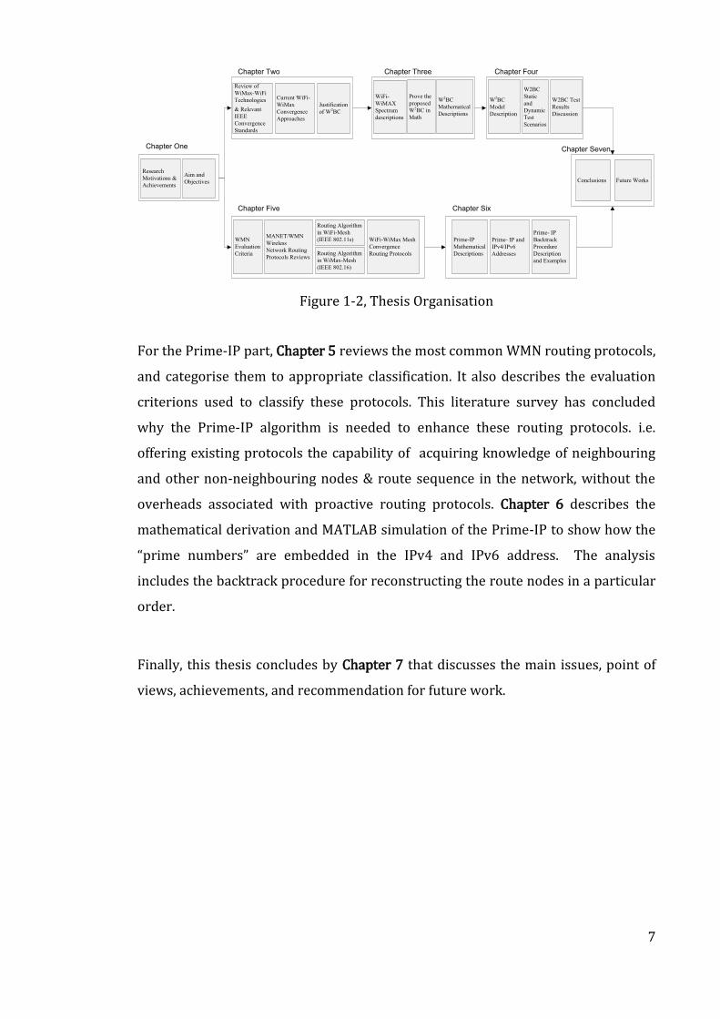
1.4. Thesis Organization
Figure 1-2 illustrates the structure of this thesis. Chapters 2, 3 and 4 are devoted to
the W2BC work, while chapters 5 and 6 focus on the Prime-IP work.
For the W2BC part, Chapter 2 reviews the latest wireless technologies in general,
followed by detailed study of WiMax & WiFi. It describes the concept of the
convergence using either protocol or implementational approaches. The motivation
of this chapter is to explain the analysis, justification, and challenges of pursuing
this approach. Chapter 3 reviews the W2BC mathematical implementation of the
baseband PHY for both WiFi-OFDM-64 and WiMax-OFDM-256. The analysis
focuses on the similarities and dissimilarities for both signals. Chapter 4 describes
the W2BC simulation model for MATLAB/Simulink. This model uses a close loop
system that cover both, the transmits and the receive chains as well as the channel.
A discussion on the appropriate static and dynamic test scenarios is laid-out. These
test scenarios are designed to prove that the functionality is maintained to the
same standard as that of stand-alone WiMax and/or WiFi transceivers.
7
Chapter Two
Review of
WiMax-WiFi
Technologies
& Relevant
IEEE
Convergence
Standards
Chapter Three
WiFi-
WiMAX
Spectrum
descriptions
Prove the
proposed
W2BC in
Math
Chapter Four
W2BC
Model
Description
Chapter One
Research
Motivations &
Achievements
Aim and
Objectives
Chapter Five
Routing Algorithm
in WiFi-Mesh
(IEEE 802.11s)
Routing Algorithm
in WiMax-Mesh
(IEEE 802.16)
MANET/WMN
Wireless
Network Routing
Protocols Reviews
WiFi-WiMax Mesh
Convergence
Routing Protocols
WMN
Evaluation
Criteria
Chapter Six
Prime-IP
Mathematical
Descriptions
Prime- IP and
IPv4/IPv6
Addresses
Prime- IP
Backtrack
Procedure
Description
and Examples
Chapter Seven
Current WiFi-
WiMax
Convergence
Approaches
Justification
of W2BC
W2BC
Mathematical
Descriptions
W2BC
Static
and
Dynamic
Test
Scenarios
W2BC Test
Results
Discussion
Conclusions Future Works
Figure 1-2, Thesis Organisation
For the Prime-IP part, Chapter 5 reviews the most common WMN routing protocols,
and categorise them to appropriate classification. It also describes the evaluation
criterions used to classify these protocols. This literature survey has concluded
why the Prime-IP algorithm is needed to enhance these routing protocols. i.e.
offering existing protocols the capability of acquiring knowledge of neighbouring
and other non-neighbouring nodes & route sequence in the network, without the
overheads associated with proactive routing protocols. Chapter 6 describes the
mathematical derivation and MATLAB simulation of the Prime-IP to show how the
“prime numbers” are embedded in the IPv4 and IPv6 address. The analysis
includes the backtrack procedure for reconstructing the route nodes in a particular
order.
Finally, this thesis concludes by Chapter 7 that discusses the main issues, point of
views, achievements, and recommendation for future work.
8
Chapter 2: Review of WiMax and WiFi
Convergence Techniques
The objectives of this chapter are to review the current techniques adapted to
convergence the WiFi and WiMax technologies, and to justify the convergence
approach proposed by this thesis.
The author believes that convergence of available data-centric wireless
technologies, the focus of this work, will greatly enhance the experience to users,
especially when communicating live and multimedia data. The author aims to
discuss these convergence technologies, reviewing their advantages and the
impediments in their implementation methods. The review shall focus on the WiFi,
WiMax and the "Media-independent handover" (or IEEE 802.21) technologies.
The motivation behind this study was to investigate the best technique to combine
WiFi and WiMax signals so to utilise the "baseband implementation chain" to
handle both of these technologies. Thus, saving device cost by using the same
baseband process instead of the current side-by-side implementations for these
two technologies. This convergence idea was initiated from the many similarities
between the WiMax and the WiFi technologies. The dissimilarities in these two
technologies, although were real obstacles to enable them communicates with each
other, but the proposed solution has overcome these issues. In general, the
dissimilarities between wireless standards are usually associated with the lower
layers, which meant that this work has to focus on these lower layers. i.e. the PHY
and MAC layers.
It important to point out that the resultant technique proposed in this thesis does
not change the WiFi or the WiMax standards. i.e. the proposed solution, instead,
actually implements these two standards in one baseband PHY layer.
9
Convergence of wireless technologies provides seamless high speed connection
while on the go. i.e. A user can have both WiFi and WiMax services available
without having to switch between these services. The benefits of these are:
Offer cheap long distance calls using VoIP over WiFi and/or WiMax
connection
Offer picture perfect video available/watched while on the move as well as
when surfing the Internet
Other benefits include simplified provisioning, easier management, less
maintenance, fewer interface, fast provisioning, newer and improved
services, and easy user interface
Thus, convergence of WiFi with WiMax will provide users with benefits of both
worlds. i.e. high speed connectivity of a LAN as well as mobility of WiMax (15).
For clarification, the following terms are used to mean:
Wireless Convergence: The Oxford dictionary meaning of convergence is
"the action or fact of converging, movement directed toward or terminating
in the same point (called the point of convergence)", (16) page 939. Thus,
for wireless technologies, the same converging concept can apply when two
or more protocols are combined in function & implementation, then they
can be regarded as converging into one for that function execution.
WiMax-WiFi Baseband Convergence-W2BC: The W2BC acronym has been
adopted to signify a "single baseband PHY layer implementation chain" that
serves both WiFi and WiMax.
10
2.1. Review of the WiMax and WiFi Technologies
2.1.1. WiMax –WiFi Convergence Review
Converging various wireless and mobile communications technologies has been
taking the centre stage of research recently. This is an ever growing and expanding
theme. The focal point of this thesis was to investigate the possibilities of
combining different wireless standards, focusing on WiMax and WiFi for the
implementation and testing.
Today, WiFi is everywhere. WiFi forms the backbone of most wireless high speed
WLAN connectivity delivered to millions of offices, homes and public locations such
as hotel, cafes and airport. WiFi is enabled in almost every notebook, PDA and
consumer electronics devices allowing connectivity on demand (17). WiMax
technology complements wireless internet access providing claimed higher data-
rates but more importantly offers wider coverage area and mobility (802.16e). As a
consequence, in some countries, WiMax has been established as a substitute to
wired-DSL, providing competitive broadband service at a competitive cost (18). A
Bridging solution for a heterogeneous WiMax-WiFi scenario, interconnecting WiFi
and WiMax standards has been proposed in (2). This approach promises much
higher date rate compared with cellular networks with much reduced
infrastructure cost. Also, this approach is fully compatible with IP networks, which
was regarded as the key factor for future broadband convergence networks.
The integration of 802.11 and 802.16 into one WiFi/WiMax module has been also
been discussed extensively in the following publications (1), (19), (20), (21), all of
which propose approaches for the realization of an internetworking between these
two standards. (19), proposes a common framework that allows the operation of
802.11 and 801.16 with optimal bandwidth sharing. Game theory and genetic
algorithm have been used to obtain pricing for bandwidth sharing between WiMax
BS and WiFi APs/routers, taking into account the bandwidth demand of the WiFi
users. (1), has discussed the Impact of wireless (WiFi, WiMax) on 3g and Next
11
Generations cellular networks. The paper concluded that operators are expected to
focus on the roll out of what so called "Pico cells" to support the growing demands
for voice and high-speed mobile data services. It further concludes that WiMax &
WiFi could also complement third-generation cellular networks by offering a
similar experience over a large area. In (20), the proposal was focused on airtime-
based link aggregation for WiFi and WiMax. i.e. the airtime cost was used to
measure the available resources of heterogeneous wireless links, where it was
calculated on a packet basis for single user. (22), concludes that the convergence
services are attractive for both consumers and operators. i.e. Convergence aims to
not only make the user interaction with these multiple technologies simpler, but
also to shift the complexity from the user side into the device and network side.
So, lots of emerging wireless technologies have evolved with their own advantages
and disadvantages. Through the convergence of wireless technologies, one
technology can eliminate the shortcoming of the other. i.e. WiMax is trying to
compete with WiFi in coverage and data rate, while the inexpensive WiFi still be
very popular in both personal and business use. However, WiMax–WiFi
combination promises expedient and inexpensive broadband connectivity, which
creates a new research area and new models for the providers and subscribers,
(15). Similarly, this convergence affords the best solution to provide mobile access
in areas such as community centres and parks, whereas broadband wireless access
networks based on WiMax can provide backhaul support for mobile WiFi hotspots,
(19). It is not only convergence of the technologies (WiFi, WiMax and 3G) is
increasingly attractive in a client device to competing service providers but also it
is convergence and competition on the way to 4G. Likewise, 4G-Evolution promises
to also include improvements beyond 3G as well as nomadic and mobile versions of
fixed broadband wireless access (BWA), such as WiFi and WiMax, (23).
The author has concluded that exploring the similarities and dissimilarities among
the wireless standards is the initial step towered the convergence. In the following
sections, this thesis will discuss the developments of these two. Both WiFi and
WiMax belongs to the same IEEE standard family, thus a lot of the similarities have
12
been identified. The major similarities are in the adopted OFDM transmission
techniques and in the digital modulation types (BPSK, QPSK, 16QAM and 64 QAM).
So, this will be the common ground to initiate the proposed convergence between
them, and resolving their dissimilarities remains to be the main challenge.
2.1.2. The WiFi IEEE 802.11 Standard Group
Including being cheap, available, applicable, and has multi-vendors, WiFi has many
advantages over WiMax, although WiMax fills many gaps that have been found in
WiFi, such coverage area and mobility. WiFi is the dominant wireless technology at
the present time for wireless LAN. Tri mode WiFi (IEEE 802.11 a/b/g) is already
built in most laptop machines, PDAs and iPhones, (24). Early versions of WiFi had
less security and poor reliability with low data rate. WiFi standard developers and
vendors have tried to overcome these problems with subsequent releases of
versions IEEE 802.11i that focus on security and IEEE 802.11e that focus on QoS
(Quality of Services). Ultimately, the IEEE 802.11n, (25) has been released as a new
WiFi standard claiming to solve all the previous problems identified by using the
MIMO-OFDM mechanism, (26). i.e. IEEE 802.11n has the ability, theoretically, to
match WiMax data throughput and wireless range. The increased performance
promised by 802.11n WLAN could eliminate the last bottleneck enterprise-wide
WLAN deployment.
The security improvement (802.11i) and the MIMO-OFDM mechanism (802.11n)
have extensively enhanced WiFi usage. These enhancements have enthused the
task group (TGs) to define the Extended Service Set (ESS) Mesh Networking
Standards. Presently, the WiFi mesh draft standard has been released as IEEE
802.11s. A lot of challenges against the 802.11s have to be harmonized to
efficiently provide a large bandwidth over a large coverage area, (27).
13
2.1.3. The WiMax IEEE 802.16 Standard Group
World Interoperability for Microwave Access (WiMax) is the trade name of the
IEEE 802.16 standard. 802.16d is the WiMax FIXED standard, while 802.16e is the
WiMax MOBILE version of the standard. The WiMax technology in its current form
will complement the WiFi 802.11 standard. The deployment and adoption of the
802.16e standard could decrease the number of WiFi users in favour of increasing
WiMax users and WiMax “hot spots.” The 802.16d standard will help corporations
and Internet service providers by expanding their services to rural markets or the
“last mile”, (28), (29).
WiMax is designed to meet the requirements of the last-mile applications of
wireless technology for broadband access with mobility, high bit rate, security and
long distance coverage. The 802.16 is a set of evolving IEEE standards that are
applicable to a vast array of the spectrum ranging from 2GHz to 66 GHz, which
presently include both licensed and unlicensed (licence exempt) bands, (30). The
IEEE 802.16 is the enabling technology standard that is intended to provide
Wireless Metropolitan Area Network (WMAN) access to locations, usually
buildings, by the use of exterior illumination typically from a centralized base
station (BS), (31).
In 2001 the IEEE 802.16 standard was released, whereas the groups continued to
modify it to work on NLOS (Non Line-of-Sight) deployments. These modifications
have covered the licensed and licensed-exempt bands between 2GHz-11GHz. In
2003 the IEEE 802.16a was released with an extending OFDM techniques added for
supporting the multi-path propagation problem. Meanwhile, the IEEE 802.11n
standard group has also evolved the OFDM as apart of the physical layer of the
WiFi. Besides the OFDM physical layers, the 802.16a established an optional MAC-
Layer functions that including supports for Orthogonal Frequency Division Multiple
Access (OFDMA), (15).
14
In 2004, revisions to IEEE 802.16a were made which called IEEE 802.16-2004. It
replaces 802.16, 802.16a and 802.16c with a single standard. Moreover, this
revised standard was also adopted as the basis for HIPERMAN (High-Performance
Metropolitan Area Network) by ETSI (European Telecommunication Standards
Institute). In 2005, 802.16e-2005 was completed, a further MAC-PHY layers
modification were formulated by using a scalable OFDM to accommodate high-
speed mobility, (32).
In addition to Point-to-Point (PTP) and Point-to-Multi Point (PMP) topologies, the
802.16a introduces the WiMax-mesh topology. This topology gains flexibility,
reliability and nomadic network architecture based on multi-hop model. Adding
the mesh concept to the 802.16 enlarges the geographical area of any network.
2.1.4. Historical Development of the OFDM Technology
Most multi-carriers wireless technologies use the OFDM (Orthogonal Frequency
Division Multiplexing) signal multiplexing method including WiFi and WiMax.
OFDM advantages over other multiplexing technologies include its elegant handling
of multipath propagation, ISI (Inter-Symbol Interference) and channel fading
problems efficiently. However, OFDM-transmitter’s Front-end is costly to make and
is power inefficient. This is especially a problem in the uplink stage when the
handset is powered from a battery, (33).
In this context, (34) argues that using a single carrier technique is better than using
OFDM in terms of data rate and the packet error rate (PER). I.e. the single carrier
technique achieves better data rate when used by portable device for usage in
indoors environment. However, the new wireless standards such WiMax and WiFi
are being developed under the OFDM techniques because, from cost/performance
point of view, OFDM came out as more attractive solution. At the same era, (35)
has proposed the use of a mixed OFDM downlink and single carrier uplink for the
IEEE 802.16. This will benefit from the features of both technologies to make cost
15
effective Customer Premises Equipment (CPE) with Non-Line Of Sight (NLOS)
operation capability. Eventually, the final draft of the IEEE 802.16 has not approved
Ran’s approach to avoid the dissimilarities between the downlink and the uplink
methods. Either case, it was concluded that the advantage of using OFDM and/or
single carrier techniques are application dependent. (32), has proposed an
architecture of scalable OFDM Physical layer for IEEE 802.16. This concept was
then approved by the by IEEE 802.16 task group. This concept enables the PHY
layer to deliver optimum performance channel bandwidth from 1.25 MHz to 20
MHz while keeping the product cost low. i.e. This architecture is based on scalable
sub-channelisation structure with variable FFT size (channel FFT size is chosen
according to channel bandwidth and supporting other features like Advanced
Modulation and Coding (AMC), Hybrid Automatic Repeat Request (H-ARQ) and
Multiple Input Multiple Output (MIMO)). Furthermore, (36) have implemented a
WiFi 802.11a transceiver using a parameterised OFDM IP blocks. These highly
reusable IP blocks, which can be instantiated with different parameter for different
OFDM based protocols, are then used for a WiMax IEEE 802.16 transceiver. The
overall design of the two transceivers was amalgamated together with 85% sharing
of the OFDM designs was achieved, resulting in reduced cost of manufacturing such
radios on silicon.
2.2. Review of Relevant IEEE Convergence Standards
A lot of terminologies are used to describe the multi standards approaches such as
combination, integrations, cross standards, mixed standards, heterogeneous and
convergence. Wireless network convergences are considered to combine more than
standards in one device. Recently, various multimedia applications such as video
streaming and VoIP services have become popular. Therefore; Bandwidth, mobility
and converge area are the main demanded parameters that should be improved.
The IEEE wireless standard for integration groups are developing to rise above
these demands by creating new amendments for internetworking with external
networks. The convergence can be done in any layer among the seven OSI layers
and the easiest way is to choose upper layers convergence; however more delay
16
and jitter will be experienced. Consequently, the fastest convergence solution is
working at lower layer (MAC and PHY), but at the expense of complexity to the
system. The developments are going through different approaches, and more
details in the following sections:
2.2.1. The IEEE 802.11u- Internetworking with External Networks
It is a proposed amendment to the IEEE 802.11 standards to add feature that
improve internetworking with external networks that include other 802 based
networks such as 802.16 ,802.3, and non-802 networks as 3GPP based IMS (IP
Multimedia subsystem) networks through subscription serves provider network
(SSPN). In this case, internetworking refers to MAC layer enhancements that help
selection of a network and allow higher layer functionality to provide the overall
end to end solution. It is also permit an emergency Call support, authorization from
Subscriber Network and Media Independent Handover Support, (4).
2.2.2. The IEEE 802.16.4- WirelessHUMAN
Its associated industry consortium, WiMax, promise to deliver high data rates over
large areas to a large number of users in the near future (e.g. IEEE 802.16a, e and
Mesh). This standard specifies the MAC/PHY layers of the air interface of
interoperable fixed point-to-multipoint broadband wireless access systems which
enables transfer DATA and VIOP with high QoS. The PHY layer is specified for both
licence and licence-exempt bands and designed for public network access. This
standard will be based on modifications of the IEEE 802.16 MAC layer, while the
PHY layer will be based on the OFDM mechanism of IEEE 802.11a and similar
standards, (5).
17
2.2.3. The IEEE 802.21- Media Independent Handover
The IEEE 802.21 standard, approved at the IEEE-SA (IEEE Std 802.21 2008),
specifies procedures that facilitate handover decision making. It enables handover,
mobility and interoperability between heterogeneous network types including
IEEE 802, non IEEE 802 and other cellular networks. IT provides the joint at layer 2
(or layer 2.5) to make any two radio technologies work together as one. IEEE
802.21b Task Group approved on Jan-2009 amendment that enables the
optimization of handovers between IEEE 802.21 supported technologies and
downlink-only (DO) technologies. IEEE 802.21c Task Group proposes a new
amendment named “Optimized Single Radio Handovers”. There is a need to develop
optimized single radio handover solutions between heterogeneous wireless
networks. Dual radio operation requires multiple radios to be transmitting and
receiving at the same time. This leads to platform noise and co-existence issues for
radios operating in close proximity frequency bands and generally leads to
increased cost of mobile device due to need for RF isolation, sharper filtering or
active cancellation, apart from increased design complexity. This amendment
defines protocols that will mitigate these issues by enabling controls for having
only a single radio transmitting at any time during the entire handover process.
This will simplify design of mobile devices and reduce service interruption time
during handovers, (3).
2.3. Current WiMax –WiFi Convergence Approaches
WiMax-WiFi convergence is a technology that provides the best of both worlds in
that WiMax new features can be offered at the low cost of WiFi. In order to create a
heterogeneous network between WiMax and WiFi, differences between these two
technologies (see section 3.1) have been investigated and resolved.
There are two camp activities in wireless convergence based on OFDM. One camp
focuses on consolidating the protocols to adopt both WiMax and WiFi data, (3), (4),
(5), while the other camp focus on consolidating the implementation of the
18
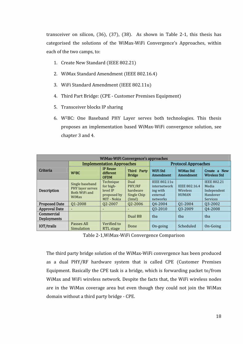
transceiver on silicon, (36), (37), (38). As shown in Table 2-1, this thesis has
categorised the solutions of the WiMax-WiFi Convergence’s Approaches, within
each of the two camps, to:
1. Create New Standard (IEEE 802.21)
2. WiMax Standard Amendment (IEEE 802.16.4)
3. WiFi Standard Amendment (IEEE 802.11u)
4. Third Part Bridge: (CPE - Customer Premises Equipment)
5. Transceiver blocks IP sharing
6. W2BC: One Baseband PHY Layer serves both technologies. This thesis
proposes an implementation based WiMax-WiFi convergence solution, see
chapter 3 and 4.
WiMax-WiFi Convergence’s approaches
Criteria
Implementation Approaches Protocol Approaches
W2BC IP Reuse different OFDM
Third Party Bridge
WiFi Std Amendment
WiMax Std Amendment
Create a New Wireless Std
Description
Single baseband PHY layer serves Both WiFi and WiMax
Technique for high-level IP proposed by MIT - Nokia
Dual PHY/RF hardware Single Chip (Intel)
IEEE 802.11u internetworking with external networks
IEEE 802.16.4 Wireless HUMAN
IEEE 802.21 Media Independent Handover Services
Proposed Date Q1-2008 Q2-2007 Q2-2006 Q4-2004 Q1-2004 Q3-2002 Approval Date - - - Q3-2010 Q3-2009 Q4-2008 Commercial Deployments
Dual BB tba tba tba
IOT/trails Passes All Simulation
Verified to RTL stage
Done On-going Scheduled On-Going
Table 2-1,WiMax-WiFi Convergence Comparison
The third party bridge solution of the WiMax-WiFi convergence has been produced
as a dual PHY/RF hardware system that is called CPE (Customer Premises
Equipment. Basically the CPE task is a bridge, which is forwarding packet to/from
WiMax and WiFi wireless network. Despite the facts that, the WiFi wireless nodes
are in the WiMax coverage area but even though they could not join the WiMax
domain without a third party bridge - CPE.
19
Alvairan and Motorola have developed a CPE in 2006, but this solution is not
competitive due to the high cost per customer comparing to another alternatives.
The thesis has focused on the possibilities of get rid of the CPE (thirds party) and
split its tasks between the WiFi side and the WiMax side, (Chapter 3 and 4).
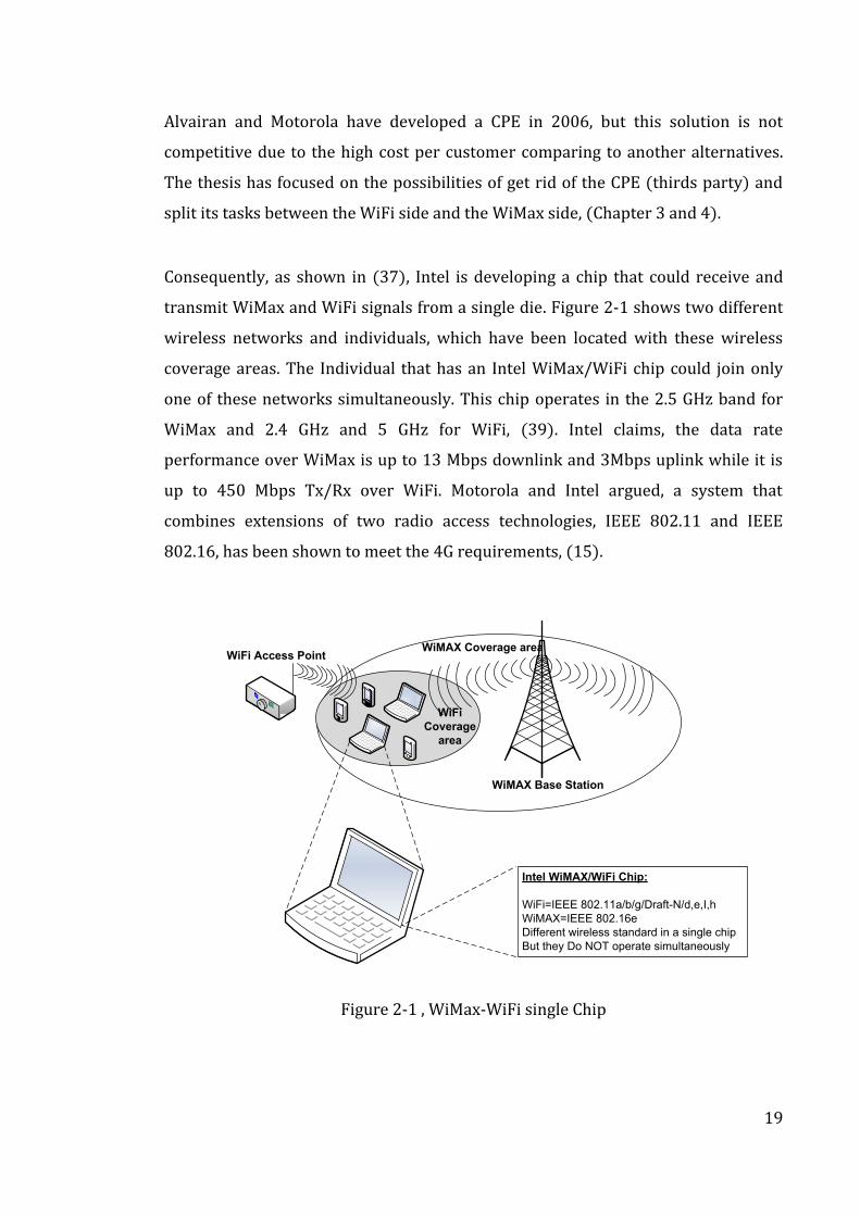
Consequently, as shown in (37), Intel is developing a chip that could receive and
transmit WiMax and WiFi signals from a single die. Figure 2-1 shows two different
wireless networks and individuals, which have been located with these wireless
coverage areas. The Individual that has an Intel WiMax/WiFi chip could join only
one of these networks simultaneously. This chip operates in the 2.5 GHz band for
WiMax and 2.4 GHz and 5 GHz for WiFi, (39). Intel claims, the data rate
performance over WiMax is up to 13 Mbps downlink and 3Mbps uplink while it is
up to 450 Mbps Tx/Rx over WiFi. Motorola and Intel argued, a system that
combines extensions of two radio access technologies, IEEE 802.11 and IEEE
802.16, has been shown to meet the 4G requirements, (15).
WiMAX Base Station
WiMAX Coverage area
WiFi
Coverage
area
Intel WiMAX/WiFi Chip:
WiFi=IEEE 802.11a/b/g/Draft-N/d,e,I,h
WiMAX=IEEE 802.16e
Different wireless standard in a single chip
But they Do NOT operate simultaneously
WiFi Access Point
Figure 2-1 , WiMax-WiFi single Chip
20
The other solutions that proposed by the IEEE Standards Association, shown in (3),
First: emerging IEEE standard 802.21 for media-independent handover services
supports “seamless” mobility between IEEE 802.11 and IEEE 802.16. This mobility
integrates the two radio access technologies into one system. It has been suggested
that an 802.11VHT + 802.16m + 802.21 system is likely to be proposed for the 4G
technology, (40). Second: IEEE 802.16.4 standard will be based on modifications of
the IEEE 802.16 MAC layer, while the PHY layer will be based on the OFDM
mechanism of IEEE 802.11a and similar standards, (5). Third: IEEE 802.11u
working group that was chartered to allow devices to interworking with external
networks, as typically found in hotspots. In this case, interworking refers to MAC
layer enhancements that allow higher layer functionality to provide the overall end
to end solution, (27).
The Thesis proposal is to find a cost effective approaches to satisfy the convergence
in the multi carrier (OFDM) wireless networks, as shown in, (10). In the Multi-
Carrier OFDM aspects of WiMax-WiFi Convergence the mismatch in the number of
FFT samples cannot be resolved at the MAC layer, and we deal with it as a physical
layer issue by creating a WiMax-WiFi Baseband Convergence-W2BC (chapter 3).
2.4. Justification of the W2BC Wireless Convergence
This section is concerned with WiMax-WiFi convergence justification. The
Convergence as mentioned above is a smart modification in PHY layers that
implements a single baseband PHY layer that serves both WiFi and WiMax wireless
technologies. Base on the research conducted in this area, this thesis has
categorised these contributions into five justifications:
1. Optimal throughput and pricing for bandwidth: Broadband wireless access
networks based on WiMax can provide backhaul support for mobile WiFi
hotspots. It has been considered to integrate WiMax/WiFi network and create a
model for optimal pricing for bandwidth where the licensed WiMax spectrum is
21
shared by the WiFi access points/routers to provide Internet connectivity to
mobile WiFi users, (19). Furthermore, the thesis looked at options where the
WiFi node may have the choice to by pass the WiFi APs, and connect directly to
the WiMax BB. The thesis proposes a controller evaluates the economics of duty
such connecting directly to the WiMax may be cheaper, or vice-versa, than
connecting via WiFi. The thesis further proposes that kind of controller is
integrated within both protocols (i.e. in the upper layers).
2. Wireless Mesh Network: Wireless Mesh Networks (WMNs) have been an
emerging technology for providing cost effective broadband Internet access.
Merging WiFi and WiMax networks offer seamless connectivity for users, (41).
It is now commonly accepted in that wireless backbone of a WMN is built using
IEEE 802.11s technology. This has been strengthened by the emergence of the
IEEE 802.16j standard accommodate for WiMax-MESH mode connectivity. This
also enforces the idea of the convergence in the Wireless Mesh Network
technologies (WiMax and WiFi), (27), (42). Section 5.6 discusses the WiFi-
WiMax convergence in Wireless Mesh Network.
3. The IEEE 802.21: The Network Working Group of the WiMax Forum is currently
investigating the issues of WiMax-3GPP interworking. Their proposed
solutions, and that of the IEEE 802.21 Task Group, are looking into providing
seamless handover solutions across heterogeneous networks. This convergence
scenario would eventually encompass complimentary and alternative network
technologies, such as UMA and fixed-mobile convergence, where advanced
mobility and radio resource management would be considered in their global
context, (3) , (43).
4. The 4G standard: The WiFi-WiMax convergence proposed by this thesis will
further be a candidate for the 4G technologies integration. i.e. the collaborations
between several technologies allow mobile users to stay connected with the
best network while roaming from one base station to another. For example, the
video telephony applications can be delivered via 3G networks, while heavy
22
files uploading or downloading can be accomplished simultaneously via global
broadband access networks like WiMax and WiFi. , (44), (45).
5. Commercial impact: This study proposes merging the two baseband silicon into
a single one. i.e. implementing one Baseband PHY layer to serve both
technologies. Thus, reducing the silicon area for the PHY by 85%, (36), (46).
2.5. Summary
As shown in the above literature survey part of this research work, convergence of
wireless technologies achieves not only functional benefits but also can save silicon
cost when done at the implementation level. The above research focused on
combining the function similarities of WiMax and WiFi when they are not working
concurrently. i.e. these functions are part of the lower layers of these two protocols
(PHY and MAC layers).
The proposed solution does not alter either standard, instead, it propose the
implementation of the two standards in a single baseband PHY layer. This solution
consolidates the functions of WiFi and WiMax and does not eliminate the
importance of each of these technologies in their own rights. i.e.
The motivation behind this study is to utilize the baseband implementation chain
so to handle both WiFi and WiMax base band signal. Thus, achieving much design
cost saving in silicon implementation where baseband processes are normally
implemented side-by-side using similar independent resources.
The arrival of the planned new protocols standards (802.11u, .16.4 and .21) can
take advantage of this implementation thus achieving further savings.
23
Chapter 3: WiMax-WiFi Baseband Convergence
(W2BC)
The focus of the W2BC work is to share a single implementation of the baseband
chain in the PHY layer between WiMax and WiFi signals. The objective of this
chapter is to describe the mathematical derivation of the multi-Carrier signal
convergence proposed in this thesis. This mathematical model illustrates how the
proposed W2BC works and how it relates to the existing standalone WiMax and
WiFi PHY layers. Two specific modulation techniques, the WiMax-Fixed (OFDM-
256) and the WiFi-OFDM-64, have been selected as an example to demonstrate this
multi-carrier convergence.
The conception of this convergence idea was formed due to the similarities
between the WiMax and WiFi functions at this layer. These same functions can be
implemented by a single Baseband PHY layer to serve both these technologies.
It has been established that dissimilarities between wireless-standards are
typically present at the lower layers. i.e. Protocol stack comparative investigations
are typically focused on the PHY and MAC layers of the wireless technologies in
question. Previous similar work has established that convergence in WiMax-WiFi
multi-carrier OFDM is a physical layer issue, (1). The proposed W2BC does not
suggest changing the standard itself, but instead, to combine the functions of the
two WiMax and WiFi implementations into one Baseband PHY implementation
using Software Defined Radio (SDR) concept, (36). i.e. by using software controlled
by the application layer to switch the PHY functions from one technology signals to
the other.
As detailed in the IEEE standard of WiFi (25), and WiMax (47), both technologies
use the orthogonal frequency division multiplexing (OFDM) transmission
24
techniques and the same digital modulation types (BPSK, QPSK, 16QAM and 64
QAM). Therefore, convergence at the PHY layer shall reduce the
basestation/handset cost significantly. i.e. same silicon block is used for both
technologies. Also, controlling the signal selection of the convergence at the PHY
layer may increases the complexity of the baseband chip (48), especially when this
control can be easily implemented by software at the application layer.
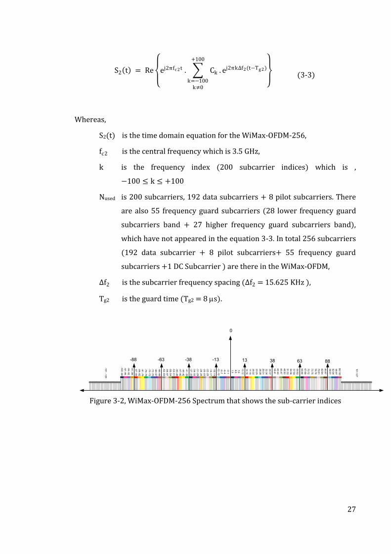
3.1. WiFi-WiMax Spectrum Description
The IEEE 802.11a,n WiFi standards have 2.4GHz or 5GHz carrier centre frequencies
respectively, while the IEEE 802.16 WiMax OFDM –TDD standard has a 3.5GHz
carrier centre frequency, (49). Figure 3-3 shows these two different OFDM
spectrums in their respective frequency bands, plotted around their centre
frequency, where, the WiMax-OFDM number of samples (NFFT) is 256 and the WiFi-
OFDM NFFT is 64. This mismatch in NFFT is a physical layer issue therefore it can be
solved by creating the W2BC to harmonize the mismatch.
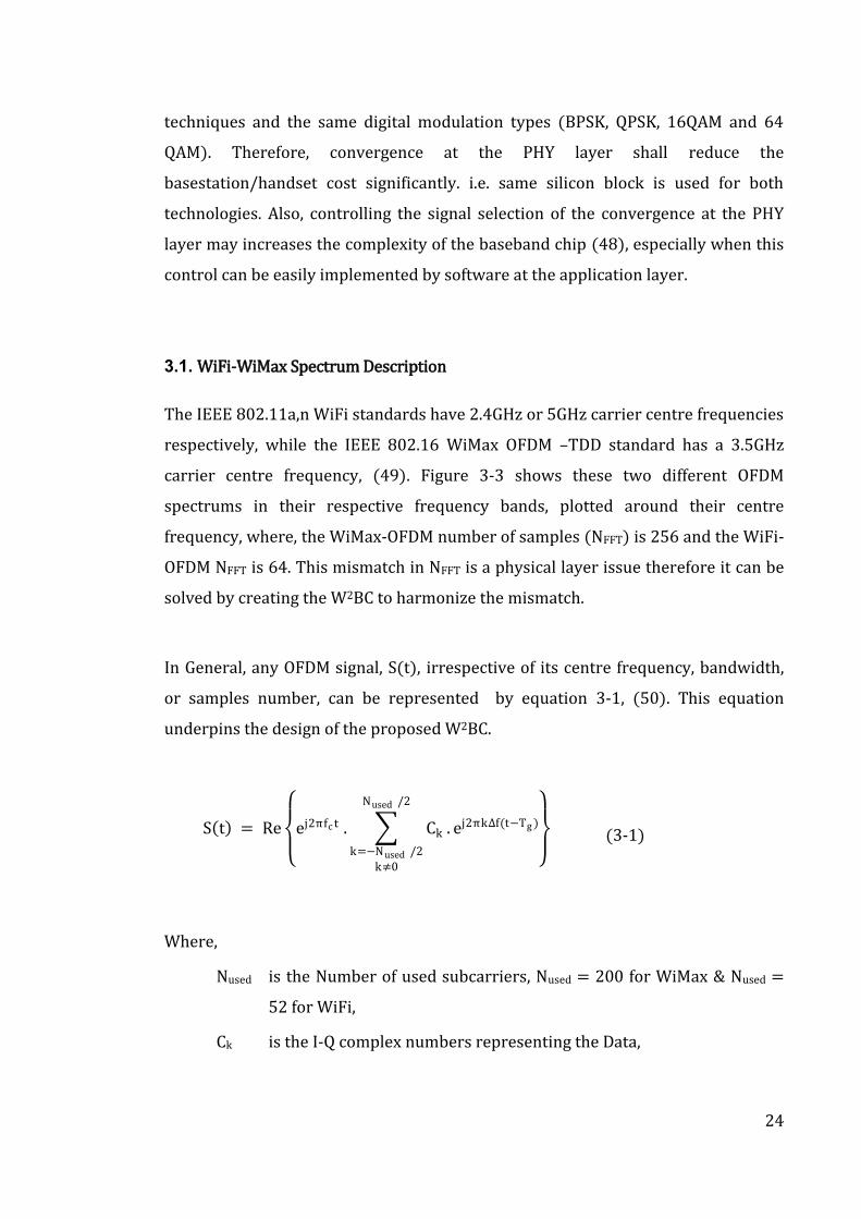
In General, any OFDM signal, S(t), irrespective of its centre frequency, bandwidth,
or samples number, can be represented by equation 3-1, (50). This equation
underpins the design of the proposed W2BC.
S t) = Re
ej2πfc t . Ck
Nused /2
k=−Nused /2
k≠0
. ej2πk∆f(t−Tg )
(3-1)
Where,
Nused is the Number of used subcarriers, Nused = 200 for WiMax & Nused =
52 for WiFi,
Ck is the I-Q complex numbers representing the Data,
25
∆f is the subcarriers frequency spacing, ∆f = 15.625 KHz for WiMax & ∆f
= 312.5 KHz for WiFi,
fc is the carrier centre frequency,
Tg is the Guard Time, Tg = 8.0 s for WiMax & Tg = 0.8 s for WiFi
Mathematically, equation 3-1 consists of three main parts:
The Carrier signal ej2πfc t at fc, where fc is the factor for deciding which
technology is being used.
The transmitted Data Ck, where k is the “subcarriers frequency offset index”
for one sample.
The Subcarriers signals ej2πk∆f(t−Tg ), where one symbol is equal to the
summation of the NFFT samples of the orthogonal subcarriers.
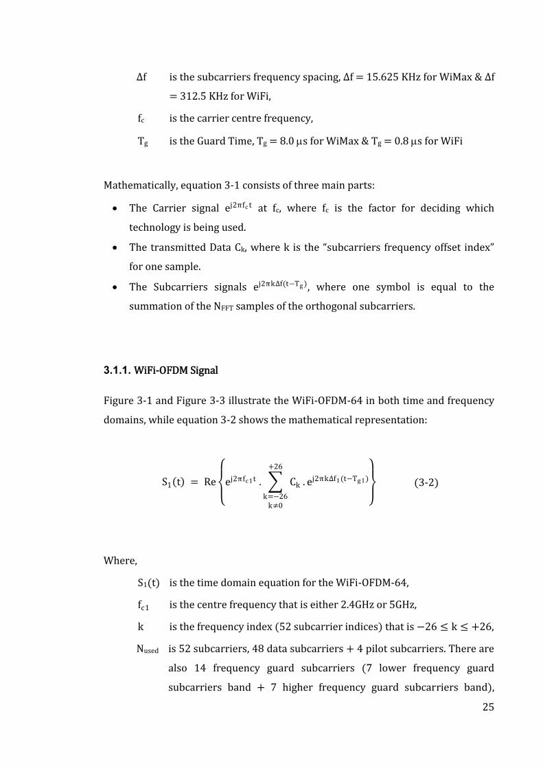
3.1.1. WiFi-OFDM Signal
Figure 3-1 and Figure 3-3 illustrate the WiFi-OFDM-64 in both time and frequency
domains, while equation 3-2 shows the mathematical representation:
S1 t) = Re
ej2πfc 1t . Ck
+26
k=−26k≠0
. ej2πk∆f1(t−Tg1)
(3-2)
Where,
S1(t) is the time domain equation for the WiFi-OFDM-64,
fc1 is the centre frequency that is either 2.4GHz or 5GHz,
k is the frequency index (52 subcarrier indices) that is −26 ≤ k ≤ +26,
Nused is 52 subcarriers, 48 data subcarriers + 4 pilot subcarriers. There are
also 14 frequency guard subcarriers (7 lower frequency guard
subcarriers band + 7 higher frequency guard subcarriers band),
26
which have not appeared in the equation. In total 64 subcarriers (48
data subcarrier + 4 pilot subcarriers+ 14 frequency guard
subcarriers) are present in the WiFi-OFDM,
∆f1 is the subcarrier frequency spacing and depends on the bandwidth
and number of FFT samples, (∆f1 = BW/NFFT)
∆f1= BW/NFFT = 20MHz/64 = 312.5 KHz,
= 10MHz/64 = 156.25 KHz,
= 5MHz/64 = 78.125 KHz,
Tg1 is the guard time (1/4∆f1),
Tg1 = 0.8 s, for 20MHz,
Tg1 = 1.6 s, for 10MHz,
Tg1 = 3.2 s, for 5MHz,
1 2 3 4 5 67
8 9 10
11
12
13
14
15
0
16
17
18
19
20
21
22
23
24
25
26 2
72
82
93
03
13
2
-26
-25
-24
-23
-22
-21
-20
-19
-18
-17
-16
-15
-1
4 -1
3 -1
2
-11
-10
-9 -8
-7 -6 -5 -4 -3 -2 -1 -3
2 -3
1 -3
0 -2
9 -2
8 -2
7
Figure 3-1, WiFi-OFDM-64 Spectrum that shows the Sub-carrier Indices
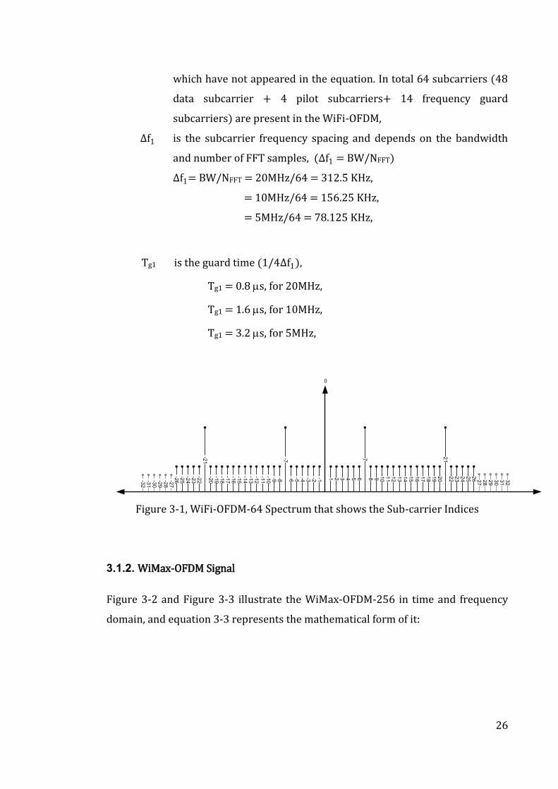
3.1.2. WiMax-OFDM Signal
Figure 3-2 and Figure 3-3 illustrate the WiMax-OFDM-256 in time and frequency
domain, and equation 3-3 represents the mathematical form of it:
27
S2 t) = Re
ej2πfc 2t . Ck
+100
k=−100k≠0
. ej2πk∆f2(t−Tg2)
(3-3)
Whereas,
S2(t) is the time domain equation for the WiMax-OFDM-256,
fc2 is the central frequency which is 3.5 GHz,
k is the frequency index (200 subcarrier indices) which is ,
−100 ≤ k ≤ +100
Nused is 200 subcarriers, 192 data subcarriers + 8 pilot subcarriers. There
are also 55 frequency guard subcarriers (28 lower frequency guard
subcarriers band + 27 higher frequency guard subcarriers band),
which have not appeared in the equation 3-3. In total 256 subcarriers
(192 data subcarrier + 8 pilot subcarriers+ 55 frequency guard
subcarriers +1 DC Subcarrier ) are there in the WiMax-OFDM,
∆f2 is the subcarrier frequency spacing (∆f2 = 15.625 KHz ),
Tg2 is the guard time (Tg2 = 8 s).
89
:91
92
:94
95
:97
98
:10
0
73
:75
70
:72
67
:69
64
:66
76
:78
79
:81
82
:84
85
:87
39
:41
42
:44
45
:47
48
:50
51
:53
54
:56
57
:59
60
:62
14
:16
17
:19
20
:22
23
:25
26
:28
29
:31
32
:34
35
:37
10
:12
7:9
4:6
1:3
-91
:-89
-94
:-92
-97
:-95
-10
0:-9
8
-28
:-26
-31
:-29
-34
:-32
-37
:-35
-22
:-20
-19
:-17
-16
:-14
-88 -63 -38 -13
0
-62
:-60
-59
:-57
-56
:-54
-53
:-51
-50
:-48
-47
:-45
-44
:-42
-41
:-39
-87
:-85
-84
:-82
-81
:-79
-78
:-76
-75
:-73
-72
:-70
-69
:-67
-66
:-64
-25
:-23
-12
:-10
-9:-7
-6:-4
-3:-1
13 38 63 88
-10
1: -1
28
10
1:1
27
Figure 3-2, WiMax-OFDM-256 Spectrum that shows the sub-carrier indices
28
WiFi-OFDM
WiMAX-OFDM
Frequency (GHz)
Amplitude
Frequency (GHz)
256 Sub-Carriers
3.5MHz Bandwidth
64 Sub-Carriers
20MHz Bandwidth
312.5 KHz Sub
Carrier Spacing
15.625 KHz
Carrier Spacing
OFDM
Symbol-S1 S2 S3 S66
Time (µs)
64 µs
72 µs
Guard Time
8µs
S67 S68 S69
Frame- 5 ms
Time (µs)
OFDM Symbol time=3.2 µs
Guard Time= 0.8 µs
WiFi-OFDM time domain signal
WiMAX-OFDM time domain signal
3.5 GHz
2.4 GHz
Figure 3-3, WiMax-OFDM, WiFi-OFDM signals (time and frequency domains)
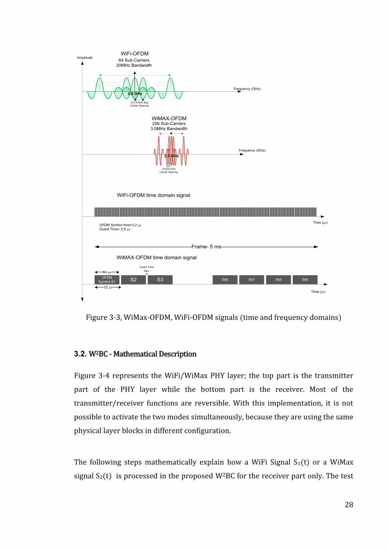
3.2. W2BC - Mathematical Description
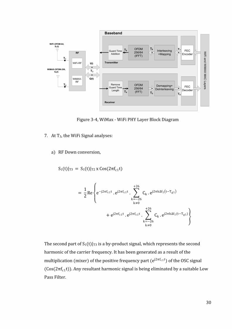
Figure 3-4 represents the WiFi/WiMax PHY layer; the top part is the transmitter
part of the PHY layer while the bottom part is the receiver. Most of the
transmitter/receiver functions are reversible. With this implementation, it is not
possible to activate the two modes simultaneously, because they are using the same
physical layer blocks in different configuration.
The following steps mathematically explain how a WiFi Signal S1(t) or a WiMax
signal S2(t) is processed in the proposed W2BC for the receiver part only. The test
29
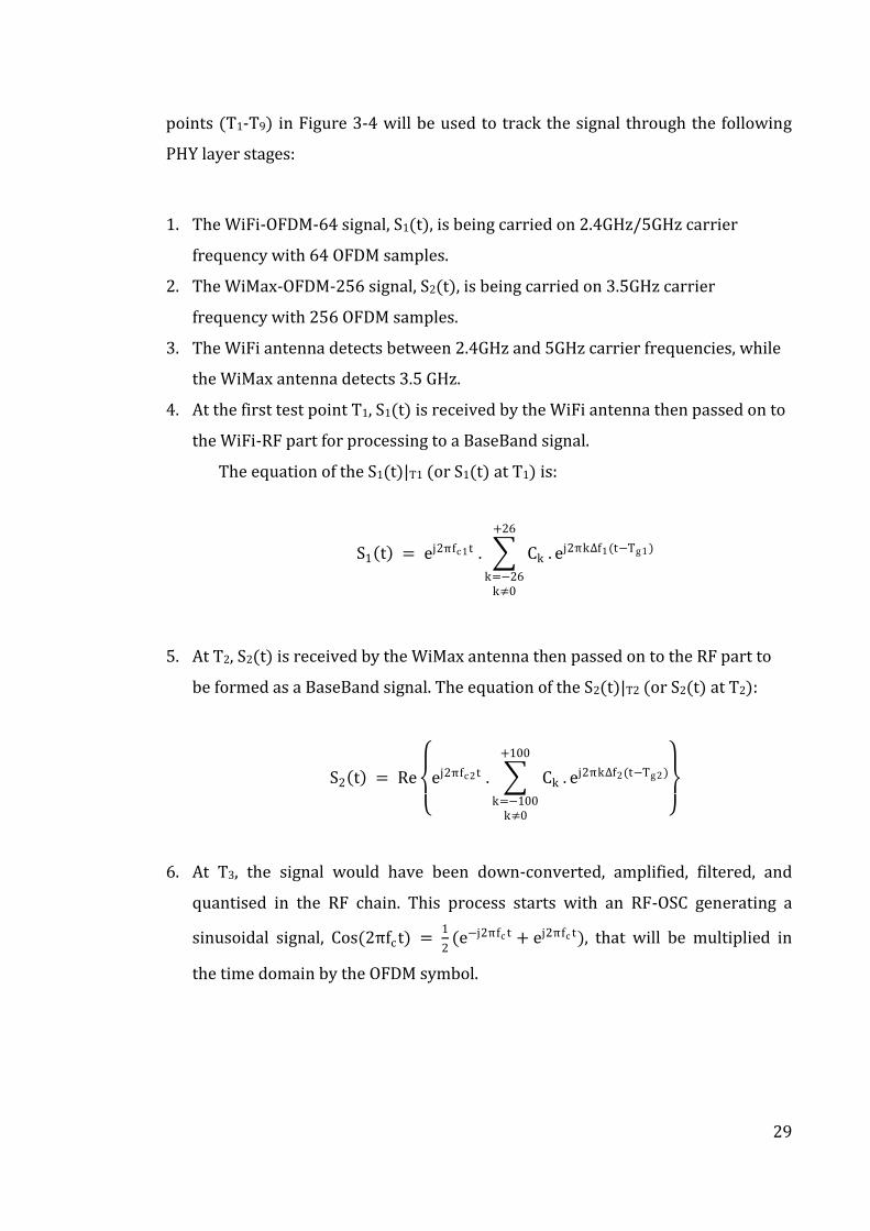
points (T1-T9) in Figure 3-4 will be used to track the signal through the following
PHY layer stages:
1. The WiFi-OFDM-64 signal, S1(t), is being carried on 2.4GHz/5GHz carrier
frequency with 64 OFDM samples.
2. The WiMax-OFDM-256 signal, S2(t), is being carried on 3.5GHz carrier
frequency with 256 OFDM samples.
3. The WiFi antenna detects between 2.4GHz and 5GHz carrier frequencies, while
the WiMax antenna detects 3.5 GHz.
4. At the first test point T1, S1(t) is received by the WiFi antenna then passed on to
the WiFi-RF part for processing to a BaseBand signal.
The equation of the S1(t)|T1 (or S1(t) at T1) is:
S1 t) = ej2πfc 1t . Ck
+26
k=−26k≠0
. ej2πk∆f1(t−Tg1)
5. At T2, S2(t) is received by the WiMax antenna then passed on to the RF part to
be formed as a BaseBand signal. The equation of the S2(t)|T2 (or S2(t) at T2):
S2 t) = Re
ej2πfc 2t . Ck
+100
k=−100k≠0
. ej2πk∆f2(t−Tg2)
6. At T3, the signal would have been down-converted, amplified, filtered, and
quantised in the RF chain. This process starts with an RF-OSC generating a
sinusoidal signal, Cos(2πfct) = 1
2(e−j2πfc t + ej2πfc t), that will be multiplied in
the time domain by the OFDM symbol.
30
WiFi-OFDM-64,
S1(t)
WiMAX-OFDM-256,
S2(t)
RF
WiF
i an
d W
iMA
X M
AC
La
ye
rs
I(t)
Q(t)
T1
T2
T3
Guard Time
Addition
OFDM
256/64
(IFFT)
Interleaving
+Mapping
FEC
Encoder
Remove
Guard Time
Length
OFDM
256/64
(FFT)
Demapping+
DeInterleaving FEC
Decoder
T9T8 T7
Baseband
Receiver
Transmitter
T4 T5 T6
WiMAX-
RF
WiFi-RF
Figure 3-4, WiMax - WiFi PHY Layer Block Diagram
7. At T3, the WiFi Signal analyses:
a) RF Down conversion,
S1(t)|T3 = S1(t)|T2 x Cos(2πfc1t)
= 1
2Re
e−j2πfc 1t . ej2πfc 1t . Ck
+26
k=−26k≠0
. ej2πk∆f1 t−Tg1
+ ej2πfc 1t . ej2πfc 1t . Ck
+26
k=−26k≠0
. ej2πk∆f1(t−Tg1)
The second part of S1(t)|T3 is a by-product signal, which represents the second
harmonic of the carrier frequency. It has been generated as a result of the
multiplication (mixer) of the positive frequency part (ej2πfc 1t) of the OSC signal
(Cos(2πfc1t)). Any resultant harmonic signal is being eliminated by a suitable Low
Pass Filter.

31
b) Low Noise Amplifier and Filtration stages,
S1 t)|T3 = Ck
+26
k=−26k≠0
. ej2πk∆f1(t−Tg1)
c) Reconstruct the I(t) and Q(t) signals,
While,
𝐂𝐤. ej2πk∆f1(t−Tg1) = 𝐈𝐤. Cos(j2πk∆f1 t − Tg1 + j.𝐐𝐤. Sin(j2πk∆f1 t − Tg1
Therefore; S1 t)|T3 could be formed as:
S1 t)|T3
= Ik
+26
k=−26k≠0
. Cos j2πk∆f1 t − Tg1
+ j. Qk
+26
k=−26k≠0
. Sin j2πk∆f1 t − Tg1
Or,
I1 t)|T3 = Ik
+26
k=−26k≠0
. Cos j2πk∆f1 t − Tg1
Q1 t)|T3 = Qk
+26
k=−26k≠0
. Sin j2πk∆f1 t − Tg1
8. At T3, for the WiMax Signal analyses :
a) RF Down conversion,
S2(t)|T3 = S2(t)|T2 x Cos(2πfc2t)
32
= 1
2Re
e−j2πfc 2t . ej2πfc 2t . Ck
+100
k=−100k≠0
. ej2πk∆f2(t−Tg2)
+ ej2πfc 2t . ej2πfc 2t . Ck
+100
k=−100k≠0
. ej2πk∆f2(t−Tg2)
b) Low Noise Amplifier and Filtration stages
S2(t)|T2 = Ck
+100
k=−100k≠0
. ej2πk∆f2(t−Tg2)
c) Reconstruct the I(t) and Q(t) signals,
S2 t)|T3
= Ik
+100
k=−100k≠0
. Cos 2πk∆f2 t − Tg2
+ j. Qk
+100
k=−100k≠0
. Sin 2πk∆f2 t − Tg2
I2 t)|T3 = Ik
+100
k=−100k≠0
. Cos 2πk∆f2 t − Tg2
Q2 t)|T3 = Qk
+100
k=−100k≠0
. Sin 2πk∆f2 t − Tg2
9. At T4 (receiver part), the guard time length is removed from the signals I(t) and
Q(t). Adding guard time (cyclic prefix) to the transmitted signal is to create an
“Inter Symbol Interference free channel ISI-free)”. The guard time is one of the
modified configuration parameters that have been highlighted in Figure 3-4. For
33
the WiFi-OFDM-64 signal the guard time is (Tg1 = 0.8 s) which represents
adding an extra 16 symbols as a cyclic prefix, while the WiMax-OFDM-256 the
guard time is (Tg2 = 8 s), which represents adding an extra 64 symbols as a
cyclic prefix. See (51), page 119, for details of OFDM cyclic prefix. i.e. This stage
prepares the IQ signals (an OFDM Symbol) to be transformed from time domain
to frequency domain using the Fast Fourier Transform stage. W2BC is designed
to transform 64 or 256 samples in the FFT. The IQ signals equations (an OFDM
symbol) will be:
a) For WiFi,
I1 t)|T4 = Ik
+26
k=−26k≠0
. Cos 2πk∆f1 t)
Q1 t)|T4 = Qk
+26
k=−26k≠0
. Sin 2πk∆f1 t)
b) For WiMax,
I2 t)|T4 = Ik
+100
k=−100k≠0
. Cos 2πk∆f2 t)
Q2 t)|T4 = Qk
+100
k=−100k≠0
. Sin 2πk∆f2 t)
10. At T5, the FFT function transforms the I(t) and Q(t) signals from time-domain
to the frequency-domain .The FFT block generates two vectors : I-vector and Q-
vector with either 64 or 256 length each. The combination of I and Q vectors
represent a single OFDM symbol. At this point the IQ-vectors (data) contain
complex numbers.
34
a) For WiFi,
I = [I1,I2,I3,….,I64] and Q = [Q1,Q2,Q3,…,Q64],
b) For WiMax,
I = [I1,I2,I3,….,I256] and Q = [Q1,Q2,Q3,…,Q256],
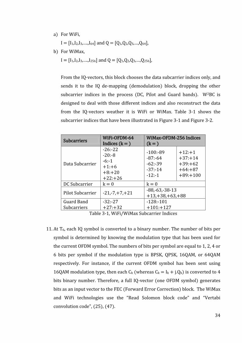
From the IQ-vectors, this block chooses the data subcarrier indices only, and
sends it to the IQ de-mapping (demodulation) block, dropping the other
subcarrier indices in the process (DC, Pilot and Guard bands). W2BC is
designed to deal with those different indices and also reconstruct the data
from the IQ-vectors weather it is WiFi or WiMax. Table 3-1 shows the
subcarrier indices that have been illustrated in Figure 3-1 and Figure 3-2.
Subcarriers WiFi-OFDM-64 Indices (k = )
WiMax-OFDM-256 Indices (k = )
Data Subcarrier
-26:-22 -20:-8 -6:-1 +1:+6 +8:+20 +22:+26
-100:-89 -87:-64 -62:-39 -37:-14 -12:-1
+12:+1 +37:+14 +39:+62 +64:+87 +89:+100
DC Subcarrier k = 0 k = 0
Pilot Subcarrier -21,-7,+7,+21 -88,-63,-38-13 +13,+38,+63,+88
Guard Band Subcarriers
-32:-27 +27:+32
-128:-101 +101:+127
Table 3-1, WiFi/WiMax Subcarrier Indices
11. At T6, each IQ symbol is converted to a binary number. The number of bits per
symbol is determined by knowing the modulation type that has been used for
the current OFDM symbol. The numbers of bits per symbol are equal to 1, 2, 4 or
6 bits per symbol if the modulation type is BPSK, QPSK, 16QAM, or 64QAM
respectively. For instance, if the current OFDM symbol has been sent using
16QAM modulation type, then each Ck (whereas Ck = Ik + j.Qk) is converted to 4
bits binary number. Therefore, a full IQ-vector (one OFDM symbol) generates
bits as an input vector to the FEC (Forward Error Correction) block. The WiMax
and WiFi technologies use the “Read Solomon block code” and “Vertabi
convolution code”, (25), (47).
35
3.3. Summary
The OFDM technique is the common ground among the multi-carriers wireless
technologies. Therefore, any OFDM signal can be generated from equation 3-1
irrespective of being a WiMax-OFDM or a WiFi-OFDM. This equation underpins the
design of the W2BC.
The mathematical derivation has clearly shown that Multi-Carrier aspects of
WiMax-WiFi Convergence for WiMax-OFDM (NFFT = 256) and the WiFi-OFDM (NFFT
= 64) is possible. This mathematical derivation can be equally used to prove for
any other NFFT samples.
The W2BC does not impact the standard itself, instead, it enables sharing the same
PHY baseband functions by multi-carrier signals, while the control of which signal
is being handled is done at the upper layers. This saves silicon area and cost at little
overheads.
36
Chapter 4: W2BC Simulation and Results
The objectives of this chapter are to describe the W2BC simulation process and to
discuss the test results for various scenarios. A closed-loop Simulink* model
representing the mathematical derivation of the W2BC (for both transmit and
receive chains) as well as a noise channel (AWGN), as shown in Figure 4-1.
MATALB* is then used to simulate various static and dynamic test-benches based
on real-world scenarios. W2BC mathematical derivation is described in chapter 3.
The test scenarios are designed to prove that the functionality and Quality of
Service (QoS), including data throughput (Bit Error Rate (BER) at various Signal to
Noise Ratio (SNR)) and WiMax-WiFi switching performance, are maintained to the
same standard as that of stand-alone WiMax and/or WiFi transceivers.
During roaming, the instructions for association/re-association of the mobile
device as it switches from one network to another (e.g. WiFi to WiMax, WiFi to a
different WiFi, etc.) are decided in the upper layers. Therefore, all measurements
are calculated for the physical layer activities only, and are based on the simulation
model of W2BC. Also, it was important to simulate a “seamless connectivity”
scenario (where for example, the mobile device is downloading a live data stream)
to prove that W2BC will not lose any of the data irrespective of the number of
network switching during this communication. The results of these test scenarios
are discussed in section 4.4.
4.1. W2BC Simulation Model Description
The W2BC mathematical derivation was described in the chapter 3. This is then
transformed to simulation model using MATALB/Simulink. Figure 4-1 shows a
block diagram of this W2BC Simulink Model. This model represents both the
receiver and the transmitter baseband functions, linked by a block of Additive
37
White Gaussian Noise (AWGN) function to form a channel for this closed- loop
system.
The “data source” block contains integer vectors to represent digital data out of an
ADC before quantisation. The vector length for the WiMax signal is 192 samples
(representing one WiMax OFDM symbol), and for WiFi signal 48 samples
(representing one WiFi OFDM symbol).
The “IQ mapper M-QAM)” and the “IQ Demapper M-QAM)” blocks transform the
sample vectors to IQ data and vise-versa, based on the modulation type selected by
the upper layers (M can be set to equal 1 for BPSK, 2 for QPSK, 4 for 16QAM, or 6
for 64QAM modulation types). See Table 4-3 for the actual IQ-Map values based on
the IEEE WiMax and WiFi standards, (25), (47).
The “OFDM Modulation” block performs the IFFT, add zero padding and add cyclic
prefix functions, while the “OFDM demodulation” block performs the reverse of
these functions. i.e. FFT, remove zero padding and remove cyclic prefix.
The AWGN block acts as a channel between the receiver and transmitter chains. It
contains a mathematical model of the channel where the only impairment to
communication is represented by a linear addition of wideband, or white noise
with a constant spectral density, (expressed as watts per hertz of bandwidth) and a
Gaussian distribution of amplitude. It allows various SNR values to be selected to
enable boundary conditions testing. By the way, for the purpose of testing the
W2BC implementation model, it does not matter which channel model is used. This
is because measurement of the switching time during the reception/transmission
process is not effected by the channel model. i.e. if there are errors due to the noise
channel, then the FEC and the higher layers will deal with it.
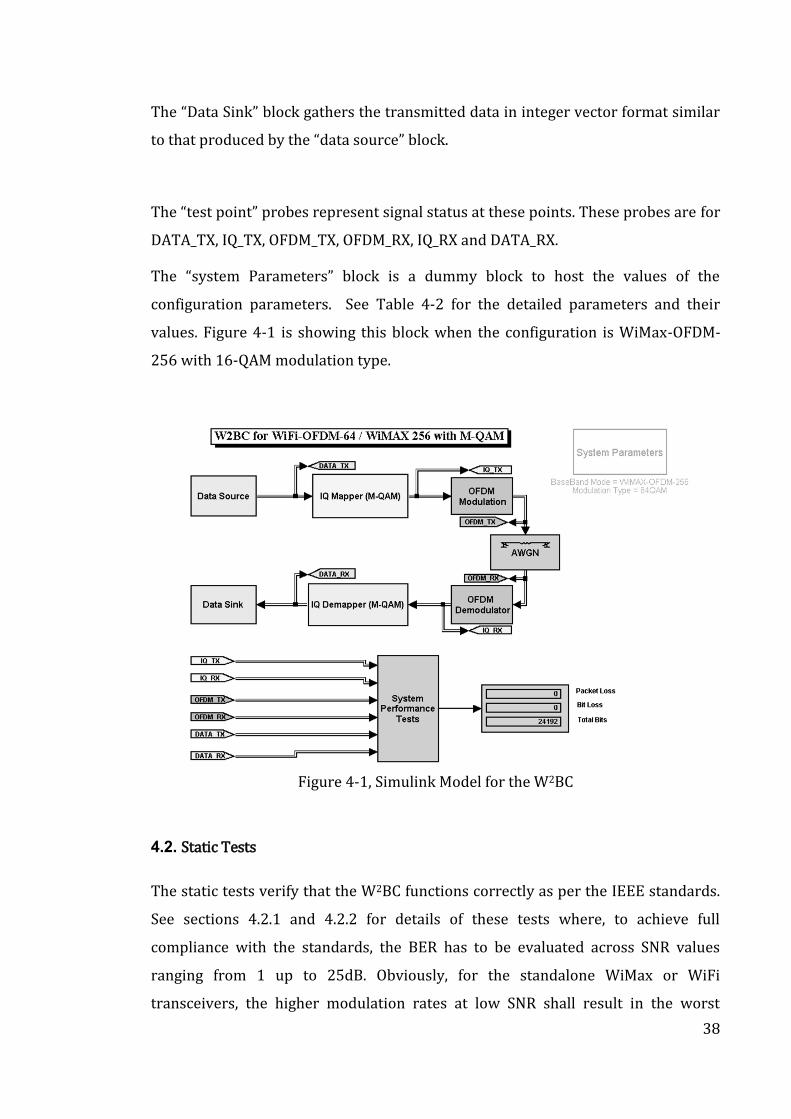
38
The “Data Sink” block gathers the transmitted data in integer vector format similar
to that produced by the “data source” block.
The “test point” probes represent signal status at these points. These probes are for
DATA_TX, IQ_TX, OFDM_TX, OFDM_RX, IQ_RX and DATA_RX.
The “system Parameters” block is a dummy block to host the values of the
configuration parameters. See Table 4-2 for the detailed parameters and their
values. Figure 4-1 is showing this block when the configuration is WiMax-OFDM-
256 with 16-QAM modulation type.
Figure 4-1, Simulink Model for the W2BC
4.2. Static Tests
The static tests verify that the W2BC functions correctly as per the IEEE standards.
See sections 4.2.1 and 4.2.2 for details of these tests where, to achieve full
compliance with the standards, the BER has to be evaluated across SNR values
ranging from 1 up to 25dB. Obviously, for the standalone WiMax or WiFi
transceivers, the higher modulation rates at low SNR shall result in the worst
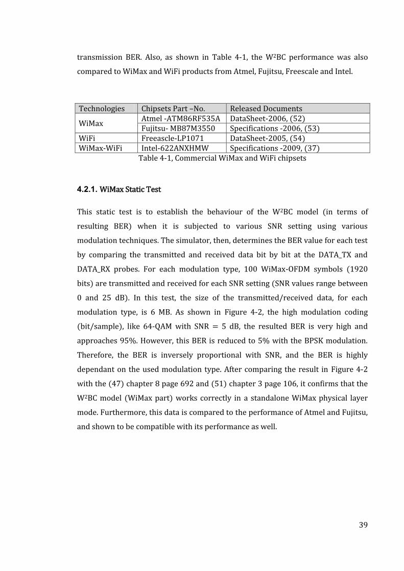
39
transmission BER. Also, as shown in Table 4-1, the W2BC performance was also
compared to WiMax and WiFi products from Atmel, Fujitsu, Freescale and Intel.
Technologies Chipsets Part –No. Released Documents
WiMax Atmel -ATM86RF535A DataSheet-2006, (52) Fujitsu- MB87M3550 Specifications -2006, (53)
WiFi Freeascle-LP1071 DataSheet-2005, (54) WiMax-WiFi Intel-622ANXHMW Specifications -2009, (37)
Table 4-1, Commercial WiMax and WiFi chipsets
4.2.1. WiMax Static Test
This static test is to establish the behaviour of the W2BC model (in terms of
resulting BER) when it is subjected to various SNR setting using various
modulation techniques. The simulator, then, determines the BER value for each test
by comparing the transmitted and received data bit by bit at the DATA_TX and
DATA_RX probes. For each modulation type, 100 WiMax-OFDM symbols (1920
bits) are transmitted and received for each SNR setting (SNR values range between
0 and 25 dB). In this test, the size of the transmitted/received data, for each
modulation type, is 6 MB. As shown in Figure 4-2, the high modulation coding
(bit/sample), like 64-QAM with SNR = 5 dB, the resulted BER is very high and
approaches 95%. However, this BER is reduced to 5% with the BPSK modulation.
Therefore, the BER is inversely proportional with SNR, and the BER is highly
dependant on the used modulation type. After comparing the result in Figure 4-2
with the (47) chapter 8 page 692 and (51) chapter 3 page 106, it confirms that the
W2BC model (WiMax part) works correctly in a standalone WiMax physical layer
mode. Furthermore, this data is compared to the performance of Atmel and Fujitsu,
and shown to be compatible with its performance as well.
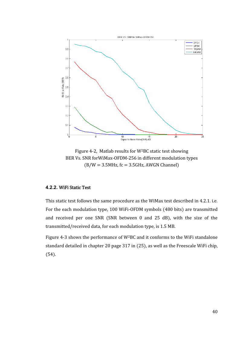
40
Figure 4-2, Matlab results for W2BC static test showing
BER Vs. SNR forWiMax-OFDM-256 in different modulation types
(B/W = 3.5MHz, fc = 3.5GHz, AWGN Channel)
4.2.2. WiFi Static Test
This static test follows the same procedure as the WiMax test described in 4.2.1. i.e.
For the each modulation type, 100 WiFi-OFDM symbols (480 bits) are transmitted
and received per one SNR (SNR between 0 and 25 dB), with the size of the
transmitted/received data, for each modulation type, is 1.5 MB.
Figure 4-3 shows the performance of W2BC and it conforms to the WiFi standalone
standard detailed in chapter 20 page 317 in (25), as well as the Freescale WiFi chip,
(54).
41
Figure 4-3, Matlab results for W2BC static test showing BER vs. SNR for WiFi-OFDM-64 in different modulation types
(B/W = 20MHz, fc = 2.4GHz, AWGN Channel)
4.3. Dynamic Tests
The W2BC offers configurability to the baseband-implementation block functions.
i.e. real time switching between WiMax and WiFi configurations dependent on
usage/requirements of the application. The instructions to switch from/to WiMax
and/or WiFi are initiated from the upper layers.
Figure 4-4, illustrates the test setup showing how the W2BC could be configured to
switch to different modes as per the configuration Table 4-2. The actual time
consumed to load configuration parameters, from the configuration list, plus the
time to configure the W2BC from one configuration setup to anther (labelled
"Switching Time" Twx from WiMax and Twf from WiFi).
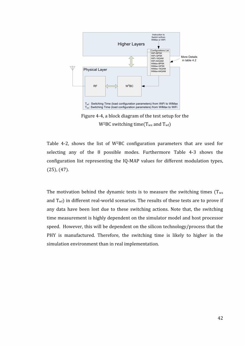
42
Higher Layers
Physical Layer
W2BCRF
Instruction to
Switch to/from
WiMax or WiFi
Twf: Switching Time (load configuration parameters) from WiFi to WiMax
Twx: Switching Time (load configuration parameters) from WiMax to WiFi
WiFi-BPSK
WiFi-QPSK
WiFi-16QAM
WiFi-64QAM
WiMax-BPSK
WiMax-QPSK
WiMax-16QAM
WiMax-64QAM
Configurations List
More Details
in table 4.2
Figure 4-4, a block diagram of the test setup for the
W2BC switching time(Twx and Twf)
Table 4-2, shows the list of W2BC configuration parameters that are used for
selecting any of the 8 possible modes. Furthermore Table 4-3 shows the
configuration list representing the IQ-MAP values for different modulation types,
(25), (47).
The motivation behind the dynamic tests is to measure the switching times (Twx
and Twf) in different real-world scenarios. The results of these tests are to prove if
any data have been lost due to these switching actions. Note that, the switching
time measurement is highly dependent on the simulator model and host processor
speed. However, this will be dependent on the silicon technology/process that the
PHY is manufactured. Therefore, the switching time is likely to higher in the
simulation environment than in real implementation.
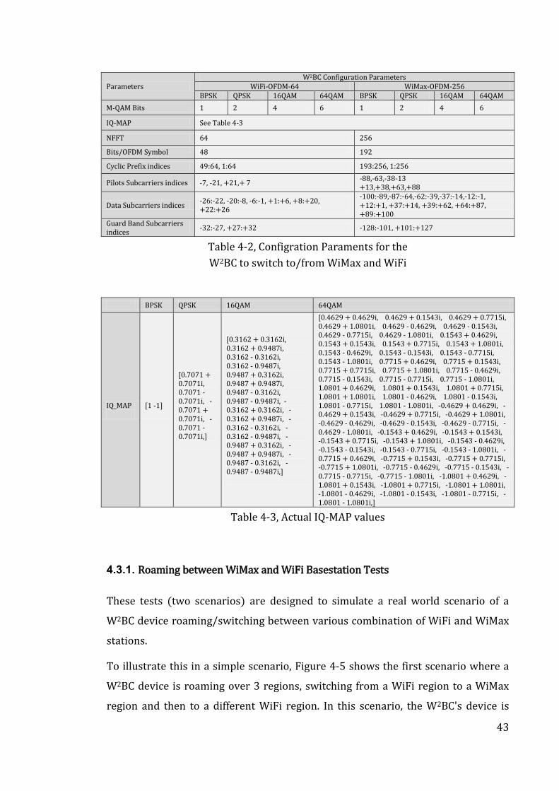
43
Parameters W2BC Configuration Parameters
WiFi-OFDM-64 WiMax-OFDM-256 BPSK QPSK 16QAM 64QAM BPSK QPSK 16QAM 64QAM
M-QAM Bits 1 2 4 6 1 2 4 6
IQ-MAP See Table 4-3
NFFT 64 256
Bits/OFDM Symbol 48 192
Cyclic Prefix indices 49:64, 1:64 193:256, 1:256
Pilots Subcarriers indices -7, -21, +21,+ 7 -88,-63,-38-13 +13,+38,+63,+88
Data Subcarriers indices -26:-22, -20:-8, -6:-1, +1:+6, +8:+20, +22:+26
-100:-89,-87:-64,-62:-39,-37:-14,-12:-1, +12:+1, +37:+14, +39:+62, +64:+87, +89:+100
Guard Band Subcarriers indices
-32:-27, +27:+32 -128:-101, +101:+127
Table 4-2, Configration Paraments for the
W2BC to switch to/from WiMax and WiFi
BPSK QPSK 16QAM 64QAM
IQ_MAP
[1 -1]
[0.7071 + 0.7071i, 0.7071 - 0.7071i, -0.7071 + 0.7071i, -0.7071 - 0.7071i,]
[0.3162 + 0.3162i, 0.3162 + 0.9487i, 0.3162 - 0.3162i, 0.3162 - 0.9487i, 0.9487 + 0.3162i, 0.9487 + 0.9487i, 0.9487 - 0.3162i, 0.9487 - 0.9487i, -0.3162 + 0.3162i, -0.3162 + 0.9487i, -0.3162 - 0.3162i, -0.3162 - 0.9487i, -0.9487 + 0.3162i, -0.9487 + 0.9487i, -0.9487 - 0.3162i, -0.9487 - 0.9487i,]
[0.4629 + 0.4629i, 0.4629 + 0.1543i, 0.4629 + 0.7715i, 0.4629 + 1.0801i, 0.4629 - 0.4629i, 0.4629 - 0.1543i, 0.4629 - 0.7715i, 0.4629 - 1.0801i, 0.1543 + 0.4629i, 0.1543 + 0.1543i, 0.1543 + 0.7715i, 0.1543 + 1.0801i, 0.1543 - 0.4629i, 0.1543 - 0.1543i, 0.1543 - 0.7715i, 0.1543 - 1.0801i, 0.7715 + 0.4629i, 0.7715 + 0.1543i, 0.7715 + 0.7715i, 0.7715 + 1.0801i, 0.7715 - 0.4629i, 0.7715 - 0.1543i, 0.7715 - 0.7715i, 0.7715 - 1.0801i, 1.0801 + 0.4629i, 1.0801 + 0.1543i, 1.0801 + 0.7715i, 1.0801 + 1.0801i, 1.0801 - 0.4629i, 1.0801 - 0.1543i, 1.0801 - 0.7715i, 1.0801 - 1.0801i, -0.4629 + 0.4629i, -0.4629 + 0.1543i, -0.4629 + 0.7715i, -0.4629 + 1.0801i, -0.4629 - 0.4629i, -0.4629 - 0.1543i, -0.4629 - 0.7715i, -0.4629 - 1.0801i, -0.1543 + 0.4629i, -0.1543 + 0.1543i, -0.1543 + 0.7715i, -0.1543 + 1.0801i, -0.1543 - 0.4629i, -0.1543 - 0.1543i, -0.1543 - 0.7715i, -0.1543 - 1.0801i, -0.7715 + 0.4629i, -0.7715 + 0.1543i, -0.7715 + 0.7715i, -0.7715 + 1.0801i, -0.7715 - 0.4629i, -0.7715 - 0.1543i, -0.7715 - 0.7715i, -0.7715 - 1.0801i, -1.0801 + 0.4629i, -1.0801 + 0.1543i, -1.0801 + 0.7715i, -1.0801 + 1.0801i, -1.0801 - 0.4629i, -1.0801 - 0.1543i, -1.0801 - 0.7715i, -1.0801 - 1.0801i,]
Table 4-3, Actual IQ-MAP values
4.3.1. Roaming between WiMax and WiFi Basestation Tests
These tests (two scenarios) are designed to simulate a real world scenario of a
W2BC device roaming/switching between various combination of WiFi and WiMax
stations.
To illustrate this in a simple scenario, Figure 4-5 shows the first scenario where a
W2BC device is roaming over 3 regions, switching from a WiFi region to a WiMax
region and then to a different WiFi region. In this scenario, the W2BC's device is
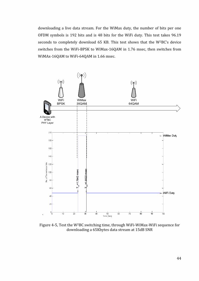
44
downloading a live data stream. For the WiMax duty, the number of bits per one
OFDM symbols is 192 bits and is 48 bits for the WiFi duty. This test takes 96.19
seconds to completely download 65 KB. This test shows that the W2BC's device
switches from the WiFi-BPSK to WiMax-16QAM in 1.76 msec, then switches from
WiMAx-16QAM to WiFi-64QAM in 1.66 msec.
WiFi
64QAM
WiFi
BPSK
A Device with
W2BC
PHY Layer
WiMax
16QAM
`
Figure 4-5, Test the W2BC switching time, through WiFi-WiMax-WiFi sequence for downloading a 65Kbytes data stream at 15dB SNR
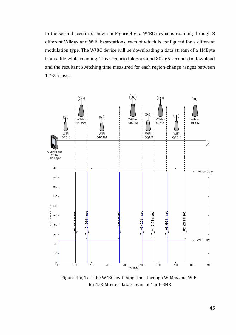
45
In the second scenario, shown in Figure 4-6, a W2BC device is roaming through 8
different WiMax and WiFi basestations, each of which is configured for a different
modulation type. The W2BC device will be downloading a data stream of a 1MByte
from a file while roaming. This scenario takes around 802.65 seconds to download
and the resultant switching time measured for each region-change ranges between
1.7-2.5 msec.
WiMax
64QAM
WiFi
64QAM
WiFi
BPSK
A Device with
W2BC
PHY Layer
WiMax
16QAM
WiFi
16QAM
WiMax
QPSK
WiFi
QPSK
WiMax
BPSK
Figure 4-6, Test the W2BC switching time, through WiMax and WiFi,
for 1.05Mbytes data stream at 15dB SNR
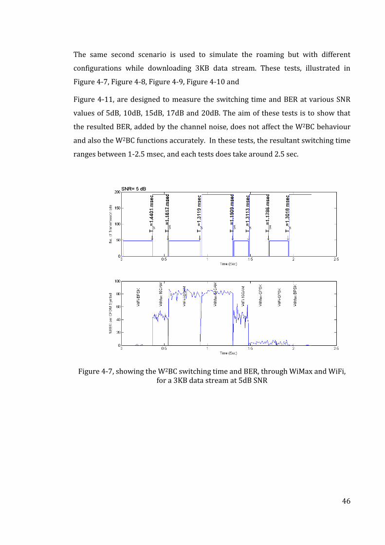
46
The same second scenario is used to simulate the roaming but with different
configurations while downloading 3KB data stream. These tests, illustrated in
Figure 4-7, Figure 4-8, Figure 4-9, Figure 4-10 and
Figure 4-11, are designed to measure the switching time and BER at various SNR
values of 5dB, 10dB, 15dB, 17dB and 20dB. The aim of these tests is to show that
the resulted BER, added by the channel noise, does not affect the W2BC behaviour
and also the W2BC functions accurately. In these tests, the resultant switching time
ranges between 1-2.5 msec, and each tests does take around 2.5 sec.
Figure 4-7, showing the W2BC switching time and BER, through WiMax and WiFi, for a 3KB data stream at 5dB SNR
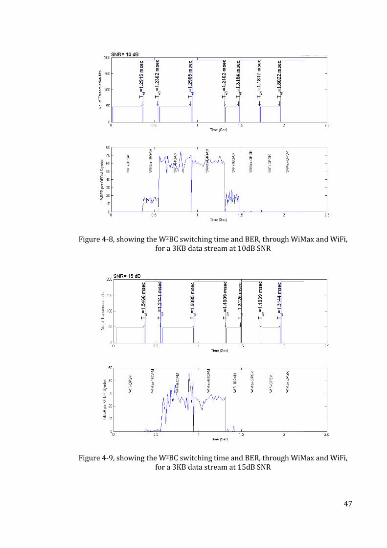
47
Figure 4-8, showing the W2BC switching time and BER, through WiMax and WiFi, for a 3KB data stream at 10dB SNR
Figure 4-9, showing the W2BC switching time and BER, through WiMax and WiFi, for a 3KB data stream at 15dB SNR
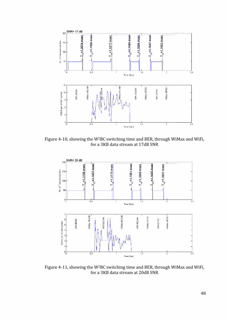
48
Figure 4-10, showing the W2BC switching time and BER, through WiMax and WiFi, for a 3KB data stream at 17dB SNR
Figure 4-11, showing the W2BC switching time and BER, through WiMax and WiFi, for a 3KB data stream at 20dB SNR
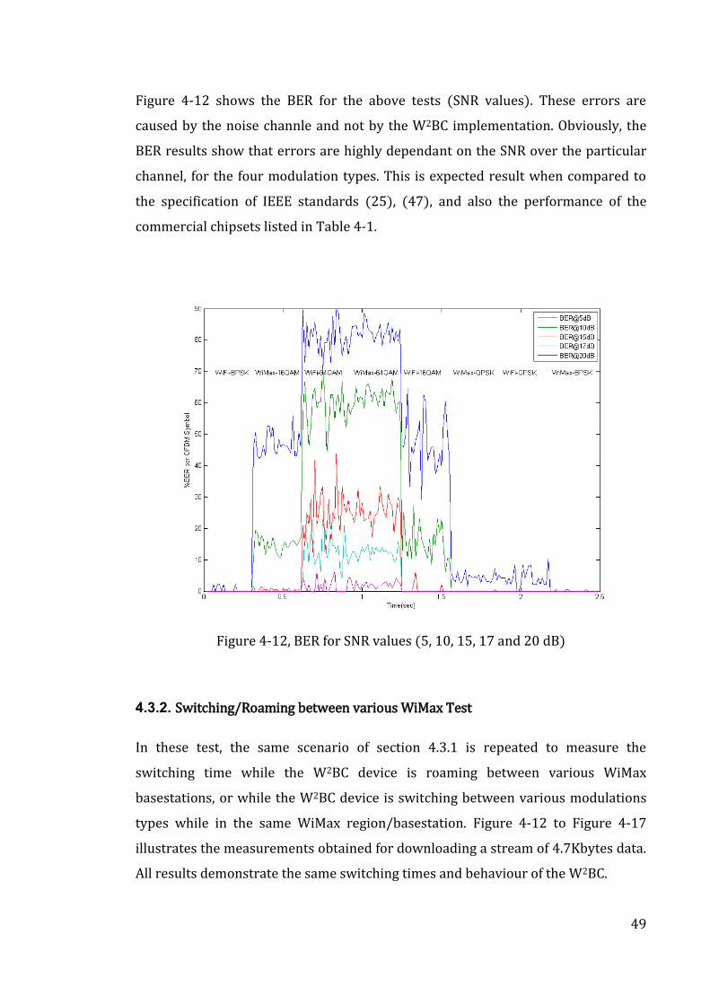
49
Figure 4-12 shows the BER for the above tests (SNR values). These errors are
caused by the noise channle and not by the W2BC implementation. Obviously, the
BER results show that errors are highly dependant on the SNR over the particular
channel, for the four modulation types. This is expected result when compared to
the specification of IEEE standards (25), (47), and also the performance of the
commercial chipsets listed in Table 4-1.
Figure 4-12, BER for SNR values (5, 10, 15, 17 and 20 dB)
4.3.2. Switching/Roaming between various WiMax Test
In these test, the same scenario of section 4.3.1 is repeated to measure the
switching time while the W2BC device is roaming between various WiMax
basestations, or while the W2BC device is switching between various modulations
types while in the same WiMax region/basestation. Figure 4-12 to Figure 4-17
illustrates the measurements obtained for downloading a stream of 4.7Kbytes data.
All results demonstrate the same switching times and behaviour of the W2BC.
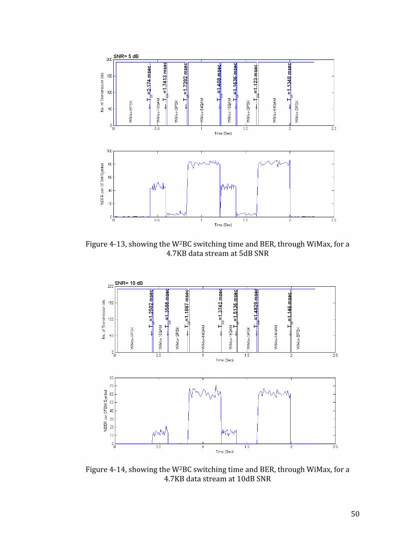
50
Figure 4-13, showing the W2BC switching time and BER, through WiMax, for a 4.7KB data stream at 5dB SNR
Figure 4-14, showing the W2BC switching time and BER, through WiMax, for a 4.7KB data stream at 10dB SNR
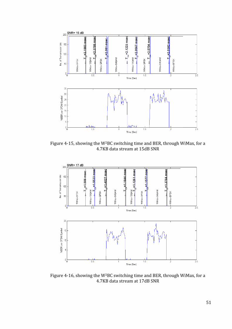
51
Figure 4-15, showing the W2BC switching time and BER, through WiMax, for a 4.7KB data stream at 15dB SNR
Figure 4-16, showing the W2BC switching time and BER, through WiMax, for a 4.7KB data stream at 17dB SNR
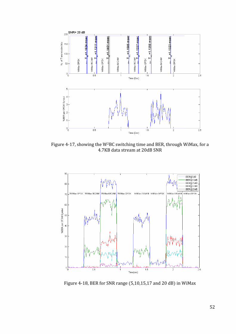
52
Figure 4-17, showing the W2BC switching time and BER, through WiMax, for a 4.7KB data stream at 20dB SNR
Figure 4-18, BER for SNR range (5,10,15,17 and 20 dB) in WiMax
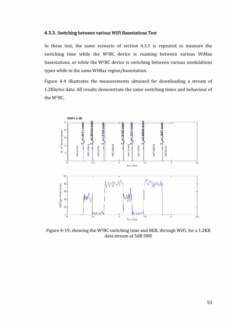
53
4.3.3. Switching between various WiFi Basestations Test
In these test, the same scenario of section 4.3.1 is repeated to measure the
switching time while the W2BC device is roaming between various WiMax
basestations, or while the W2BC device is switching between various modulations
types while in the same WiMax region/basestation.
Figure 4-4 illustrates the measurements obtained for downloading a stream of
1.2Kbytes data. All results demonstrate the same switching times and behaviour of
the W2BC.
Figure 4-19, showing the W2BC switching time and BER, through WiFi, for a 1.2KB data stream at 5dB SNR
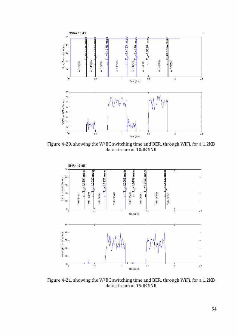
54
Figure 4-20, showing the W2BC switching time and BER, through WiFi, for a 1.2KB
data stream at 10dB SNR
Figure 4-21, showing the W2BC switching time and BER, through WiFi, for a 1.2KB data stream at 15dB SNR
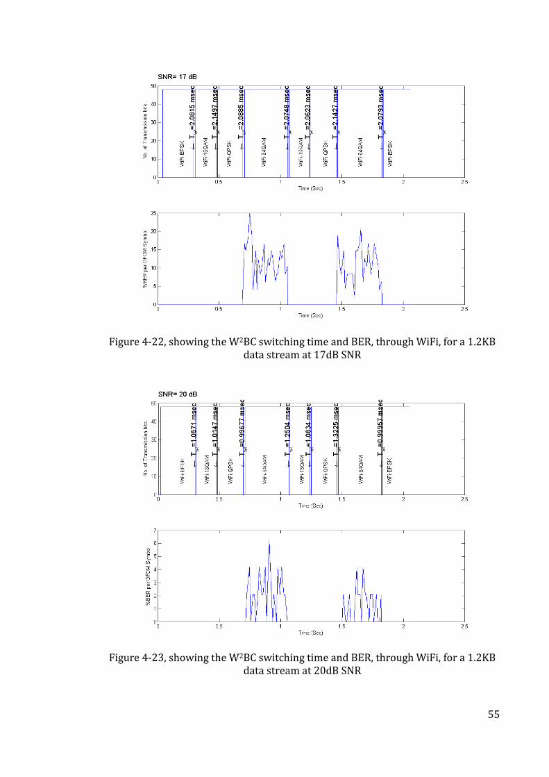
55
Figure 4-22, showing the W2BC switching time and BER, through WiFi, for a 1.2KB data stream at 17dB SNR
Figure 4-23, showing the W2BC switching time and BER, through WiFi, for a 1.2KB data stream at 20dB SNR
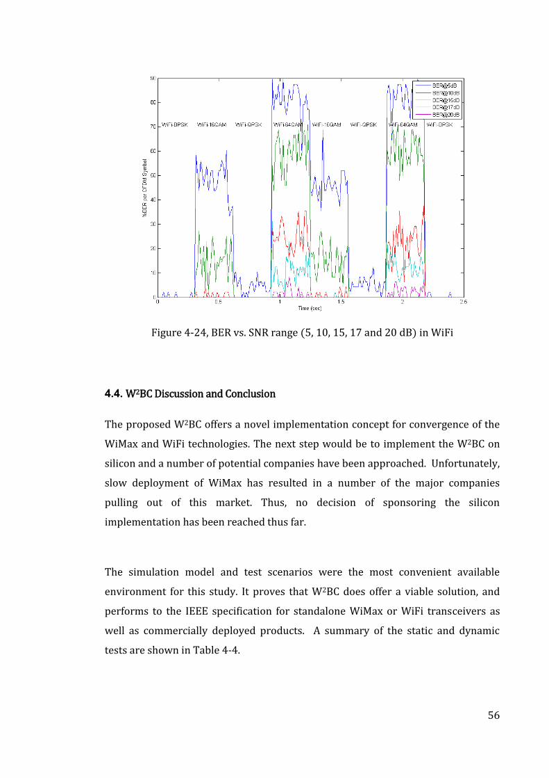
56
Figure 4-24, BER vs. SNR range (5, 10, 15, 17 and 20 dB) in WiFi
4.4. W2BC Discussion and Conclusion
The proposed W2BC offers a novel implementation concept for convergence of the
WiMax and WiFi technologies. The next step would be to implement the W2BC on
silicon and a number of potential companies have been approached. Unfortunately,
slow deployment of WiMax has resulted in a number of the major companies
pulling out of this market. Thus, no decision of sponsoring the silicon
implementation has been reached thus far.
The simulation model and test scenarios were the most convenient available
environment for this study. It proves that W2BC does offer a viable solution, and
performs to the IEEE specification for standalone WiMax or WiFi transceivers as
well as commercially deployed products. A summary of the static and dynamic
tests are shown in Table 4-4.
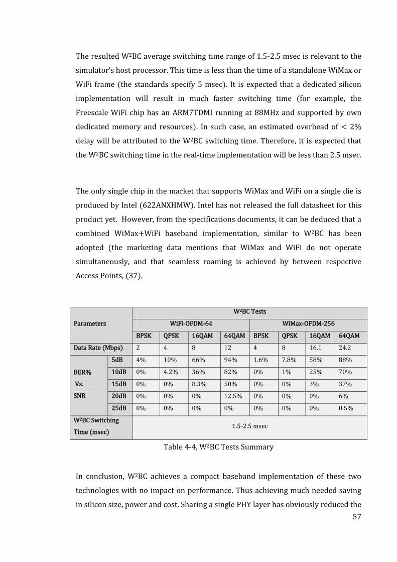
57
The resulted W2BC average switching time range of 1.5-2.5 msec is relevant to the
simulator’s host processor. This time is less than the time of a standalone WiMax or
WiFi frame (the standards specify 5 msec). It is expected that a dedicated silicon
implementation will result in much faster switching time (for example, the
Freescale WiFi chip has an ARM7TDMI running at 88MHz and supported by own
dedicated memory and resources). In such case, an estimated overhead of < 2%
delay will be attributed to the W2BC switching time. Therefore, it is expected that
the W2BC switching time in the real-time implementation will be less than 2.5 msec.
The only single chip in the market that supports WiMax and WiFi on a single die is
produced by Intel (622ANXHMW). Intel has not released the full datasheet for this
product yet. However, from the specifications documents, it can be deduced that a
combined WiMax+WiFi baseband implementation, similar to W2BC has been
adopted (the marketing data mentions that WiMax and WiFi do not operate
simultaneously, and that seamless roaming is achieved by between respective
Access Points, (37).
Parameters
W2BC Tests
WiFi-OFDM-64 WiMax-OFDM-256
BPSK QPSK 16QAM 64QAM BPSK QPSK 16QAM 64QAM
Data Rate (Mbps) 2 4 8 12 4 8 16.1 24.2
BER%
Vs.
SNR
5dB 4% 10% 66% 94% 1.6% 7.8% 58% 88%
10dB 0% 4.2% 36% 82% 0% 1% 25% 70%
15dB 0% 0% 8.3% 50% 0% 0% 3% 37%
20dB 0% 0% 0% 12.5% 0% 0% 0% 6%
25dB 0% 0% 0% 0% 0% 0% 0% 0.5%
W2BC Switching
Time (msec) 1.5-2.5 msec
Table 4-4, W2BC Tests Summary
In conclusion, W2BC achieves a compact baseband implementation of these two
technologies with no impact on performance. Thus achieving much needed saving
in silicon size, power and cost. Sharing a single PHY layer has obviously reduced the
58
size of the total baseband implantation by 35%, (36). The baseband functions that
have been made configurable in the W2BC implementation are clustered within the
Cyclic Prefix, the FFT, the OFDM and the IQ-Mapping blocks. The W2BC concept can
be expanded to cover mobile-WiMax (802.16e) OFDM-512, OFDM-1024 and so on.
The arrival of the planned new protocols standards (802.11u, 802.16.4 and 802.21)
can take advantage of this implementation thus achieving further savings.
59
Chapter 5: WMN Routing Protocols Review
The objectives of this chapter are to review the most common WMN routing
protocols and to justify how the proposed Prime-IP algorithm enhances these
protocols. i.e. enables any node in the WMN to have knowledge beyond their
nearest neighbors because, in these protocols, information is only available from
the nearest neighboring nodes only.
To aid understanding of this review, the protocols have been divided into two
groups for those that use a “basestation” or not. Each of these groups has been sub-
grouped further as shown in Table 5-1. The literature survey for this review has
been on-going since the beginning of this research work in Oct/2006. The review
includes the WiFi Mesh routing protocols (IEEE 802.11s) and WiMax Mesh routing
protocols (IEEE 80216).
Without changing the reactive routing protocols, Prime-IP focuses on maintaining
the knowledge of all nodes in all possible route paths between the source node and
the destination node irrespective of the number of intermediate nodes number.
This node knowledge is accumulated during the route discovery process.
Furthermore, for WMN routing protocols, Prime-IP enhances the current routing
protocols as well as security. The Prime-IP algorithm is described in chapter 6.
5.1. WMN Routing Protocols: Evaluation Criteria
The focus of the literature survey was to establish if the most commonly used WMN
protocols (a) accommodate knowledge of other non-neighbouring nodes in the
network, and (b) if prime numbers are used in the IP address of the nodes.
Therefore, these two criteria are used to evaluate all of these protocols without
regards to other criteria such as throughput, synchronisation, etc.
60
The dynamic topology of WMNs has invited many attempts to classify the routing
protocols based on various criterions dependent on the approaches adopted in
these publications, (7), (55), (56). Reactive routing protocols offer faster dynamic
network connectivity and self-configuration as well as scalability for large WMNs
than Proactive routing protocols because of the processing-time and hosting
overheads required to maintain/update the information about all the nodes in the
network in routing tables, (57), (58), (59), (60). However, the proactive protocols
offer better network security, Quality of Service (QoS), and network management,
(61). Hybrid solutions based on both proactive and reactive routing protocols
attempts to compromise on the benefits of both, and also incur the pitfalls of both
categories too, (62). For example, route tables are kept up to date for all node
changes within zones of limited-nodes thus offering data packet delivery with
lower end2end delay locally at a contained amount of overhead, and deploy
reactive behaviour for inter-zone connectivity thus achieving higher data packet
delivery on the expense of larger end2end delay, (63).
The idea of using the prime numbers to allocate addresses was considered by, (64).
This paper/patent proposes a Prime DHCP scheme for address allocation without
broadcasting in the whole MANET during the address allocation process. In the
proposed prime DHCP, each host serves as a DHCP proxy that can assign addresses
to new hosts by running a proposed Prime Numbering Address Allocation (PNAA)
algorithm individually to compute unique addresses for address allocation. Prime
DHCP uses the prime numbers to generate the addresses and does not embedded
the prime numbers in the IP addresses like Prime-IP does. Also, the use of DHCP
proxies and the PNAA together eliminate the need for broadcasting in the whole
MANET and do not provide solution for the routing protocols.
Table 5-1 summarises the list of WMN routing protocols surveyed in this work. The
following sections describe each of these protocols and section 5.8 concludes the
findings of this survey.
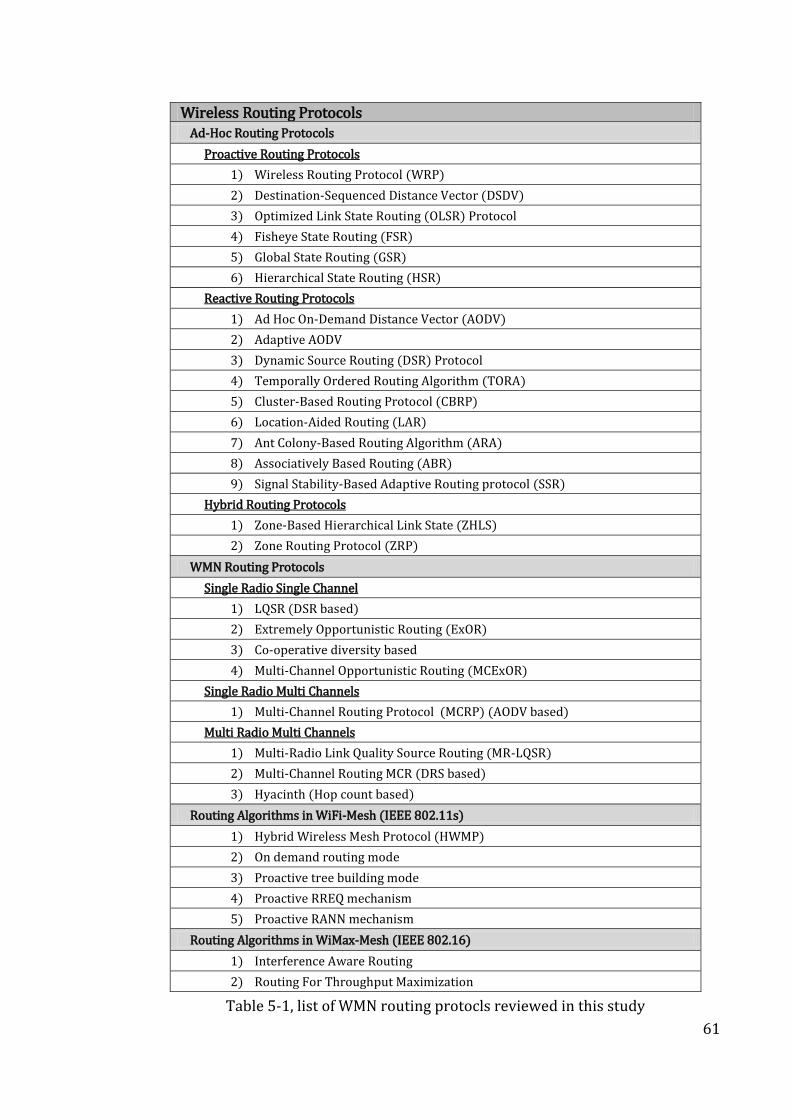
61
Wireless Routing Protocols Ad-Hoc Routing Protocols
Proactive Routing Protocols
1) Wireless Routing Protocol (WRP)
2) Destination-Sequenced Distance Vector (DSDV)
3) Optimized Link State Routing (OLSR) Protocol
4) Fisheye State Routing (FSR)
5) Global State Routing (GSR)
6) Hierarchical State Routing (HSR)
Reactive Routing Protocols
1) Ad Hoc On-Demand Distance Vector (AODV)
2) Adaptive AODV
3) Dynamic Source Routing (DSR) Protocol
4) Temporally Ordered Routing Algorithm (TORA)
5) Cluster-Based Routing Protocol (CBRP)
6) Location-Aided Routing (LAR)
7) Ant Colony-Based Routing Algorithm (ARA)
8) Associatively Based Routing (ABR)
9) Signal Stability-Based Adaptive Routing protocol (SSR)
Hybrid Routing Protocols
1) Zone-Based Hierarchical Link State (ZHLS)
2) Zone Routing Protocol (ZRP)
WMN Routing Protocols
Single Radio Single Channel
1) LQSR (DSR based)
2) Extremely Opportunistic Routing (ExOR)
3) Co-operative diversity based
4) Multi-Channel Opportunistic Routing (MCExOR)
Single Radio Multi Channels
1) Multi-Channel Routing Protocol (MCRP) (AODV based)
Multi Radio Multi Channels
1) Multi-Radio Link Quality Source Routing (MR-LQSR)
2) Multi-Channel Routing MCR (DRS based)
3) Hyacinth (Hop count based)
Routing Algorithms in WiFi-Mesh (IEEE 802.11s)
1) Hybrid Wireless Mesh Protocol (HWMP)
2) On demand routing mode
3) Proactive tree building mode
4) Proactive RREQ mechanism
5) Proactive RANN mechanism
Routing Algorithms in WiMax-Mesh (IEEE 802.16)
1) Interference Aware Routing
2) Routing For Throughput Maximization
Table 5-1, list of WMN routing protocls reviewed in this study
62
It is worth noting that none of these protocols uses the concept of prime numbers
as part of the IP address. Also, few of the “Proactive routing protocols” are capable
of having network-wide node information that was inherited from their parent
wired protocols.
5.2. MANET Wireless Network Routing Protocols (without infrastructure)
Mobile ad-hoc network (MANET) defines the group of wireless network of mobile
nodes formed without any other network infrastructure. Every node in MANET can
act as a router. These nodes are free to roam and may switch off without notice.
Thus, the topology of MANET changes rapidly as the nodes move or new nodes join
the network. This makes MANET highly dynamic and unpredictable in nature
which makes routing selection process very challenging. In some types of MANET,
such as multi-hop networks, this challenge increases due to the limited bandwidth,
the large mix of device types used in the network, high processing power, and
restricted battery power. Furthermore, MANET routing exposed more challenges
due to the limited resources available as well as the dynamically changing
environment. i.e. the routing protocol needs to handle issues such as QoS and
scalability required for various applications in varying network size, network
partitioning, traffic density, and others, (65), (66). The use of distance-vector and
link-state protocols do not work in large MANET as the frequent update of routes
take up large part of the available bandwidth as well as increase channel
contention, thereby requiring more power which is a scarce resource, in mobile
battery powered devices, (67). To overcome these problems, a number of
protocols, (68), (69), have been suggested for MANET.
The following sections describe the “Classification of routing protocols for MANET”,
(57) into 4 categories based on:
a. routing information update mechanism
b. use of temporal information for routing
c. routing topology
d. utilization of specific resources
63
5.2.1. Classification Based on the Routing Information Update Mechanism
The routing protocol based on the mechanism of updating routing information can
be divided into 3 groups, (70) of proactive, reactive and hybrid.
A. Proactive or Table Driven Protocols
In this type of protocols the route to destination is determined at the start-up and
stored by each node in the form of a table. Due to this, these protocols are also
called “table driven” protocols. This table is then updated periodically to keep
information current so that the node, whenever required, can use the information
instantly from its table. The change in network topology requires transmitting
information to all the nodes about the change. Some of the proactive protocols are,
Destination Sequenced Distance Vector routing protocol (DSDV) (71), Wireless
Routing Protocol (WRP) (65), Cluster-Head Gateway, Switch Routing protocol and
Source Tree Adaptive Routing protocol (STAR), (71).
B. Reactive or on Demand Protocols
In this type of protocol the route is determined only when needed and hence the
name “on-demand” routing protocol. The source node initiates procedure for
finding out path for a given destination and after the path is found, or in case of non
availability of any routes the procedure gets terminated. The reactive protocol for
mobile ad-hoc networks have low control overheads and also have better
scalability than proactive routing protocols. Since each time a new route is
discovered, the source node may have to wait longer for sending data packets. The
Dynamic Source Routing (DSR) Protocol (72), Ad Hoc On-Demand Distance Vector
(AODV) Routing Protocol (67), Temporally Ordered Routing Protocol (TORA) (73),
and Cluster-Based Routing Protocol (CBRP) (74), are few of the reactive routing
protocols for MANET, (75).
64
C. Hybrid Protocols
In this the mix of proactive & reactive strategies are followed to take benefit of
merits of each. The hybrid protocol normally use hierarchical network
architectures with proactive & reactive strategies used at different hierarchical
level. The nodes are segregated in zones depending on their distances form each
other or geographical location. The proactive routing is done within the zone and
reactive routing is done for nodes located beyond the zone boundary. Protocols
such as Zone Routing Protocol (ZRP), Zone-Based Hierarchical Link State (ZHLS)
Routing Protocol, and Hybrid Ad Hoc Routing Protocol (HARP) are some of the
hybrid protocols, (76).
5.2.2. Classification Based on the use of Temporal Information/Metrics for Routing
The “hop number” is used as metric or temporal information in many MANET. With
this methodology MANET can be classified into two types:
A. Using Past Temporal Information
The protocols under this category use latest status of links or metrics for taking
routing decisions. However, these types of protocol may face resource crunch in
case of sudden link breaks which will change network configuration. DSDV is one
of the protocols which use current metric information for routing, (71).
B. Using Future Temporal Information
These protocols use predictions about future status of nodes battery life, link status
and others for decision on the route. Flow Oriented Routing Protocol (FORP) which
uses prediction about future disconnection to find alternative link before link
breaks, comes under this category, (67).
5.2.3. Classification based on Utilization of Specific Resources
In this classification, the protocols groups are divided further based on the roles the
nodes are assigned.
65
A. Uniform Routing Protocols
As the name suggest all the nodes in this group perform similar role, functionality,
and are given same importance. The structure of uniform routing protocols is
normally flat. Routing Protocols WRP, DSR, AODV, and DSDV are uniform routing
protocols, (71).
B. Non-uniform Routing Protocols
Nodes in this category are assigned more and distinct routing functions as
compared to other nodes. Non-uniform routing protocols can be divided further
into zone-based hierarchical routing, cluster-based hierarchical routing, and core-
node based routing, depending on the management and routing functions, (67).
The zone-based routing protocols use different zone-constructing algorithms for
organizing nodes into different zones to reduce overheads for routing information
maintenance. In zone-based hierarchical routing protocols some nodes function as
gateway for inter-zone communication. The ZRP and the ZHLS are two such
protocols, (76).
In the cluster-based routing protocols, nodes are grouped into clusters and specific
algorithms are used for cluster head selection. Cluster-head Gateway Switch
Routing (CGSR) in one such protocol. The multilevel cluster structure, such as the
Hierarchical State Routing (HSR), is also used by some protocols, (67).
In the core based protocols some nodes are selected to act a backbone of the mobile
ad-hoc network. The backbone nodes take up functions such as routing path
construction, control etc. Core-Extraction Distributed Ad Hoc Routing (CEDAR) is a
typical core-node-based protocol, (77).
5.2.4. Classification Based on the Routing Topology
The nodes in this category use network topology to make routing decisions. Using
this classification, MANET can be divided into two types:

66
A. Flat Topology Routing
These categories of protocol assume that all nodes are peers, with each node having
its own global address. Most of the mobile ad-hoc network protocols are of this
type. Protocol DSR and AODV are flat topology protocols, (67).
B. Hierarchical Topology Routing
The protocols in this category group nodes into clusters with one node acting as
cluster head to co-ordinate with all other nodes in the cluster. The clustering can
have multilevel hierarchy. Cluster-Head Gateway Switch Routing Protocol (CGSR) is
one such protocol, (78).
Another category is the “destination-based routing” protocols, where every node
only knows the next hop along routing path. AODV and DSDV are destination-based
routing protocols. The protocols perform location based routing where the routing
is done based on position relationship between the forwarding node and
destination node. The location base protocol may use only location information or
also use topological information. Location-Aided Routing (LAR) and Distance
Routing Effect Algorithm for Mobility (DREAM) are two location-based routing
protocols for mobile ad hoc networks, (79) .
5.3. Routing Protocols for Wireless Mesh Networks (with infrastructure)
Wireless Mesh Networks (WMN) technology has emerged to combine localised
wireless technologies such as WiFi, WiMax and Bluetooth networks to connect
beyond their respective limited area. For example, a number of WiFi networks are
connected to each other using other technologies such as WiMax in between so to
make a single seamless network covering a much larger area. WMNs are mostly
used for Internet connectivity with a wireless router forming the backbone of a
typical network. Like ad-hoc networks, WMNs are also dynamically self-configured
and self-organized. However, in WMNs, most of the nodes, such as access points or
67
internet gateways, are actually mains-powered and therefore are static and have no
limitations of usage power as in the case of battery powered mobile devices that
form the MANET. The following are examples of most commonly used WMN
protocols.
5.3.1. Link Quality Source Routing (LQSR)
Link Quality Source Routing (LQSR) (80), developed by Microsoft, is a modified
version of DSR for use in their Mesh Connectivity Layer (MCL) technology for
WMN. In LQSR the routing decisions are based on some additional link quality
metrics such as ETX (Expected Transmission Count), Per-hop Round Trip Time
(RTT), Packet Pair and hop count. The nodes in WMN are assigned relative weights
to the links with other nodes. The information about channel, losses and bandwidth
of the every link is determined and sent to all the nodes. The nodes, based on all
this data, determine the best route available. LQSR modifies the change in optimum
path in case of any link breaks. In LQSR, the knowledge of nodes beyond their next
neighbouring node is not maintained. Note that, Prime-IP (see chapter-6) does
maintain the knowledge beyond the neighbouring nodes and the principles of
Prime-IP can enhance the LQSR protocol if adopted.
5.3.2. Extremely Opportunistic Routing (ExOR)
Extremely Opportunistic Routing (ExOR) work by sending the information over
multiples channels concurrently, (81), (82). The packets are broadcasted and the
nodes receiving the packets send acknowledgment back to the sender. The sender
then selects a node closest to the actual destination for further transmission of
packets. This allows transmission of packets using the nodes closest to the
destination, which may not be normally available, for data transmission in normal
propagation conditions but are available in favourable conditions. ExOR uses loss-
rate matrix, indicating probability of successful packet reception between each pair
of nodes, for transmission of packets. The information inside both the sent header
68
& the received acknowledgement header are analyzed to select the forwarding
nodes. A timed scheduling algorithm is used to co-ordinate data transfer by using
the higher priority nodes and to avoid collisions. In ExOR, the concept of
“knowledge of nodes beyond the neighbouring nodes” does not exist. Multi-
Channel Opportunistic Routing (MCExOR)
5.3.3. Multi-Channel Opportunistic Routing (MCExOR)
Multi-Channel Opportunistic Routing (MCExOR) (83) extends the ExOR protocol by
utilizing multi RF channels instead of the single channel used by the ExOR protocol.
Then it chooses the most promising channel set for every transmission. (83), have
demonstrated that the increase in number of RF channels increases the overall
throughput proportionately. They show that “MCExOR with 2 RF channels
surpasses AODV by an average of 140%”
5.3.4. Multi-Channel Routing Protocol (MCRP)
Multi-Channel Routing Protocol (MCRP) (84) uses channel switching technique by
assigning the channels to data flows instead of assigning the channels to nodes
used in normal practice. A common channel is assigned to data flow across all
nodes. This channel is available for duration of the data flow without the need for
node to switch channels. The allocation of different channel for different data flow
improves the transmission capacity by allowing simultaneous transmissions. In
MCRP the information of node beyond the next neighbouring node is not
5.3.5. Multi-Radio Link Quality Source Routing (MR-LQSR)
Multi-Radio Link Quality Source Routing (MR-LQSR) (85) is the LQSR protocol that
uses Weighted Cumulative Expected Transmission Time (WCETT) routing metric.
The MR-LQSR aims to fulfil following main objectives:
69
i. The loss rate and the bandwidth of a link should be taken into account for
selecting a path;
ii. The path metric should be increasing; and
iii. The path metric should reflect the throughput degradation due to the
interference caused by simultaneous transmissions. WCETT has used a
metric for this.
The information related to channel assignment on a link; its loss rate and
bandwidth are transmitted, as DRS control packets, to all nodes in the network.
The use of WCETT as the link gives minimal cost path in terms of link bandwidth
and loss rate. (85), reports that the route metric used in MR-LQSR is a multi-radio
environment significantly outperforms previously proposed routing metrics by
making judicious use of the second radio. MR-LQSR does not keep the information
of node beyond the next neighbouring node.
5.3.6. Multi-Channel Routing (MCR)
Multi-Channel Routing (MCR) is an on demand protocol with multi-radio Nodes.
MCR uses switching mechanism to change the channels to fully exploit available
resources. MCR takes some channels as fixed channels and treats the rest as
“dynamically assignable/switchable” channels. The list of fixed channels uses
neighbouring node & channel usage is maintained by each node. The HELLO packet
transmission by each node periodically allows each node to update its tables & its
channel usage. The MCR selects the route based on weighted sum of switching cost
(sum of Expected Transmission Time (ETT) values along the path) as well as the
channel diversity (maximum ETT cost on all channels) cost. MCR route discovery
mechanism is similar to DSR, except that information of channel number and the
switching cost is also available. The destination selects the optimum path based on
channel number and the switching cost. In MCR nodes do not have the information
of node beyond the next neighbouring node, (86), (87).
70
5.4. Routing Algorithms in WiFi-Mesh (IEEE 802.11s)
The 802.11s standard defines a mesh network as “two or more nodes that are
interconnected via IEEE 802.11 links which communicate via mesh services and
comprise an IEEE 802.11- based Wireless Distribution System (WDS), (88).” The
nodes in such mesh network are called Mesh Station (mesh STA) and the access
points in this mesh network are called Mesh Access Point (MAP). The node
supporting mesh protocol is called a Mesh Point (MP). The devices use to connect
mesh network to non-mesh network are called mesh portal. This protocol only
provides information about it neighbours & no information is provided beyond the
neighbourhood. The use of Prime-IP algorithm will enhance this protocol by this
removing this limitation and providing more information about what lies beyond
immediate neighbourhood.
5.4.1. Hybrid Wireless Mesh Protocol
The Hybrid Wireless Mesh Protocol (HWMP) (89) provides proactive tree based
routing for fixed part of network as well as the on-demand routing for mobile part
of the network. The combination of two parts provides optimal and efficient path
selection in many types of mesh networks.
The discovery of on demand routes in HWMP is based on Ad Hoc on Demand
(AODV) routing protocol and uses its set of protocol primitives, generation and
processing rules. Also, it uses some additional primitives to proactively set up a
distance-vector tree rooted at a single root mesh point.
HWMP supports following two non exclusive modes of operation depending on the
configuration:
i. On demand mode: This mode is used by MPs to communicate using peer-
to-peer routes when the root is not configured and in some other special
cases.
71
ii. Proactive tree building mode: This uses either the Route Request (RREQ)
or Root Announcement (RANN) mechanism.
The above modes may be used concurrently.
5.4.1.1. On Demand Routing Mode
To find out the route, the MP broadcasts a Route Request (RREQ) with destination
address and the metric field initialised to 0. Sequence numbers are used to avoid
loops. The MP receiving RREQ creates a route to the source if the route is new, or
updates the route stored if the RREQ contains a greater sequence number, else
offers a better metric than the current route. The new route, or change of existing
route, is forwarded along with modified RREQ which also contains the cumulative
metric of the route to the RREQ’s source. The new route is unicasted by the
destination MP back to the source using Route Reply (RREP) whenever the new
route is created or modified. The Intermediate MPs, on receiving the RREP, create a
route to the destination as well as forward a RREP back to the source. The
destination node on receiving RREQs, with a better metric this time, sends the new
route information back to source. This way allows the best metric end-to-end route
to be established between a source & destination.
5.4.1.2. Proactive Tree Building Mode
HWMP uses two methods to find out the route for reaching the root MP. The first
method uses Route Request (RREQ) message to find out routes between all MPs in
the network and the root MP. In the second method, a Root Announcement (RANN)
message is used to distribute route information for reaching the root. The root MP
periodically sends proactive RREQ and RANN messages.
A. Proactive RREQ Mechanism: In the tree building process, root MP sends
proactive RREQ message to all the nodes along with a sequence number and
metric set to zero. The root MP sends these messages periodically, with
increasing sequence numbers. The MP record/update their forwarding
72
information to the root MP, the metric and hop count using an RREQ message
before forwarding the updated RREQ. This allows MP’s to indicate their
“availability and distance” to the root MP and to all the nodes in the network.
The MP’s check the sequence number & updates their route if the sequence
number is >= (greater than or equal) to the number of current route, or if a
better metric is available. The RREQ is processed as described for the on-
demand mode using RREP so to set the shortest path.
B. Proactive RANN Mechanism: The root MP periodically broadcasts a Root
Announcement (RANN) message to the network. The MP receiving RANN
creates, or updates, the route and sends unicast RREQ to the root via the
same route as it receives the RANN message. The root then responds to each
RREQ by sending RREP. This creates a bi-directional route. The change of
route from MP to root is informed to MPs by sending RREP with the
addresses of the MPs that have established the route to the root through the
current MP.
5.5. Routing Algorithms in WiMax-Mesh (IEEE 802.16)
In IEEE 802.16d, point to point mode of communication takes place between the
Mesh base station (MBS) and subscriber stations (SS). This differs from mesh mode
communication that can take place between subscriber stations within a mesh
directly as well as outside the mesh, using MBS as shown in Figure 5-1 below:
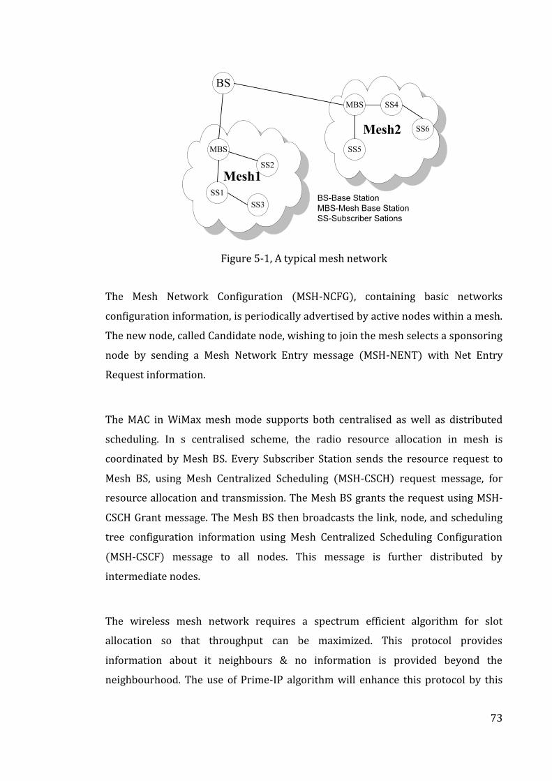
73
Mesh1
Mesh2
BS
MBS
MBS
SS3
SS1
SS2
SS5
SS4
SS6
BS-Base Station
MBS-Mesh Base Station
SS-Subscriber Sations
Figure 5-1, A typical mesh network
The Mesh Network Configuration (MSH-NCFG), containing basic networks
configuration information, is periodically advertised by active nodes within a mesh.
The new node, called Candidate node, wishing to join the mesh selects a sponsoring
node by sending a Mesh Network Entry message (MSH-NENT) with Net Entry
Request information.
The MAC in WiMax mesh mode supports both centralised as well as distributed
scheduling. In s centralised scheme, the radio resource allocation in mesh is
coordinated by Mesh BS. Every Subscriber Station sends the resource request to
Mesh BS, using Mesh Centralized Scheduling (MSH-CSCH) request message, for
resource allocation and transmission. The Mesh BS grants the request using MSH-
CSCH Grant message. The Mesh BS then broadcasts the link, node, and scheduling
tree configuration information using Mesh Centralized Scheduling Configuration
(MSH-CSCF) message to all nodes. This message is further distributed by
intermediate nodes.
The wireless mesh network requires a spectrum efficient algorithm for slot
allocation so that throughput can be maximized. This protocol provides
information about it neighbours & no information is provided beyond the
neighbourhood. The use of Prime-IP algorithm will enhance this protocol by this
74
removing this limitation and providing more information about what lies beyond
immediate neighbourhood.
Some of the algorithms proposed for WiMax wireless mesh networks are given
below:
5.5.1. Interference Aware Routing
Interference Aware Routing (90) is aimed to provide a centralised mesh scheduling
scheme which takes into account the demand as well as interference conditions.
The modelling of interference level is done by a blocking metric B(k) of a given
route from the Mesh BS toward an SS node k. The blocking metric B(k) in a multi-
hop environment to show the number of blocked or interfered nodes by the
intermediate nodes in route between the root node and the destination node k. The
number of blocked nodes are given by a number called blocking value b(η) of a
transmitting node η. The blocking metric of the route is the sum of the blocking
values of nodes that transmit or forward packets along the route.
The interference aware algorithm consists of two parts:
A. Inference Aware Route Construction: Using this scheme the routes with
minimum interference is selected by comparing the blocking metric for the
different routes to the destination from the source and then selecting the
best route.
B. Interference Aware Scheduling: The interference-aware scheduling is used
to increase the system throughput by exploiting concurrent transmission
but keeping interference under control. To do this, the traffic capacity
request of each SS is considered. The capacity request of an SS node from k
denoted by D(k) can be represented in terms of Y(j) for every link j. The set
of active links is calculated by scheduling algorithm for each allocation
iteration t. The next allocation to traffic is assigned to the link with highest
unallocated traffic demand and by excluding interfering links are located in
the neighbourhood of k using Blocked_Neighbor(k) function. This iterative
allocation goes on till the allocation demand is fulfilled. Interference-Aware
75
Routing does not keep the information of node beyond the next
neighbouring node as in Prime-IP and hence the use of Prime-IP can
enhance its efficiency further.
5.5.2. Routing For Throughput Maximization
The (91) algorithm, in addition to using blocking metric of a route has taken the
number of packets into account. The blocking metric B(v) of the node v was taken
as the number of blocked nodes multiplied by the number of packets at the node v.
The path with minimum B(v) is selected.
The proposed system constructs the routing tree when new node enters the
network using broadcast messages MASH-NCFG and MASH-NENT from the new
node. The network is then reconfigured by MBS by recalculating the routing node
and broadcasting the MASH-CSCH message to the SS’s. The MBS periodically
recomputed the routing tree with updated data and changes routing tree if
required. This algorithm categorised into two types:
A. Maximum Parallelism Routing: The aim of this routing algorithm to maximize
the parallelism while taking number of packets into account. The algorithm
segregates interfering and non interfering pair of edges between two
consecutive layers. The edge pair is weighted with the number of packets at the
sender node. The set of non-interfering edges with maximum weights on the
edge is selected by the algorithm.
B. Min Max Degree BFS Tree: Here the breadth first search (BFS) is conducted so
that the maximum degree of the tree is minimized and takes advantage of the
shortest path (breadth first tree) with least bottlenecks. The periodic re-
computation of the routing tree results in extra overhead in these algorithms.
These algorithms do not keep the information of node beyond the next
neighbouring node as in Prime-IP and the use of Prime-IP can enhance their
efficiency further. The considered the Max Weight scheduling algorithm, which
extends Fair Queuing, by considering the distance of the node to the BS. The
author used Line Scheduling algorithm which further extended the Max Weight
by considering fairness of each node
76
5.5.3. Other Routing Protocols
(92) proposed routing and centralised scheduling depending on different traffic
models (i.e. CBR, VBR) to support QoS. In this paper, the Authors took the routing
tree as a shortest path routing as it is more effective in deciding the overall
performance of the network. The authors provided a finite horizon dynamic
programming framework to optimize a cost function over a fixed number of time
slots, and using the resultant cost function,, they proposed the algorithm for
maximizing the network throughput.
Another algorithm was presented (93), with the aim of maximizing the network’s
capacity using concurrency among the multi-hop transmissions. The authors
proposed algorithm for SS so that the concurrent transmission in both uplink and
downlink streams is feasible with no collision to improve the overall end-to-end
throughput.
ROMER, (94), was yet another algorithm proposed to provide a resilient
opportunistic mesh routing by providing balance between short term opportunistic
performance and long-term route stability. In this, the mesh is centred around
minimum cost and long term stable path but can expand or shrink to exploit the
availability of high quality & high data rate links that may be available for short
time. The algorithm selects the high data rate link for forwarding the data. At the
same time the data is also sent from other route randomly to provide for redundant
path to take care of lossy links, transient node outage, etc. It was demonstrated that
ROMER was able to achieve about 68-195% higher throughput gain over single
path routing as well as providing better packet delivery ratio than multi-path
routing.
77
5.6. WiMax-WiFi Mesh Convergence Routing Protocols
The properties of WiFi make it more suitable for dense small area network, while
WiMax provides large coverage and is more suitable for sparsely populated areas.
The integration of these two protocols can bring benefits of both types of these
networks.
The first level integration makes use of WiFi for small areas & WiMax for
interconnecting the small areas networks into one big network with point to
multipoint capability.
The second level of integration can be achieved by using WiMax to form a
mesh network at broader levels or metro scale areas of WiFi networks. The
system once deployed with WiMax in mesh and in the PMP (Point-to-Multi
Point topology) can utilize enhanced quality of service (QoS) features of
WiMax MAC for enforcement of service level agreements (SLAs).
The third level of integration is to use a hybrid device with integrated WiFi
and WiMax (based on 820.16e) technologies side by side. This will enable
seamless connection to both networks, (41), (95). The emerging IEEE
standard 802.21 for media-independent handover services will support
seamless mobility between IEEE 802.11 and IEEE 802.16, by integrating the
two radio access technologies into one system.
Proxim, (96), has come out with MeshMAX product line which integrates three,
WiMax, WiFi Mesh and WiFi technologies, in one small unit. MeshMAX is an
outdoor tri-radio. It offers WiFi connectivity for access, WiFi mesh gateway for
network redundancy and a high capacity WiMax link for backhaul. The integrated
device offers end-to-end QoS for triple-play applications leading to substantial
reduction in the cost of ownership. The device is also capable of upgrading to future
developments in WiMax technology. The user of this device can select WiFi access
functions as well as connect to WiMax base station through WiMax subscriber unit
with QoS and bandwidth control.
78
(97), have suggested a hybrid WiFi-WiMax network routing protocol for an
integrated network. The system uses gateway for interconnection of two networks.
The proposed hybrid protocol aims to “offer users of adhoc network broadband
service a device that can select the best route in terms of bandwidth, battery
residual energy and distance". The protocol proposed can find best routes within
WiMax and provide automatic reconnection in case of route failure. The authors
have based their algorithm on Ad-hoc On Demand Distance Vector (AODV)
protocol. The modelling was done using OPNET. To find a route, the source node
sends a RREQ packet till it reaches destination or the WiFi/WiMax gateway. If the
node is outside coverage area, the RREQ packet is resent and the destination node
or WiFi/WiMax gateway gives reply using RREP packet to source node. The hybrid
algorithm proposed does not keep the information of node beyond the next
neighbouring node.
5.7. Wireless Routing Protocol in IPv6
The Wireless Routing Protocol in IPv6 environment can take advantage of various
features of IPv6 addressing. The use of 128 bit IP address in IPv6 allows virtually
unlimited number of users each having unique address. In IPv6 environment, each
of the mobile host can have a valid global IP address and with stateless auto-
configuration RFC 2462) this can be done without user’s intervention. The other
advantages of using IPv6 will be that the protocols can take advantages of it’s built
in security features, simpler configuration and mobility features.
The mobility support has been extended to IPv6 in the form of a new protocol call
Mobile IPv6. This protocol allows a mobile device to move from one location to
another without change of its IP addresses, (98). As the mobile moves, it is assigned
a “care of” address which contains the subnet prefix of the mobile’s home address.
The Mobile IPv6 protocol uses route optimization signalling for advertising about
its care-of address to its correspondent node allowing the exchange of packets
using shortest path between the two. The WiMax ASN gateway, when encounters
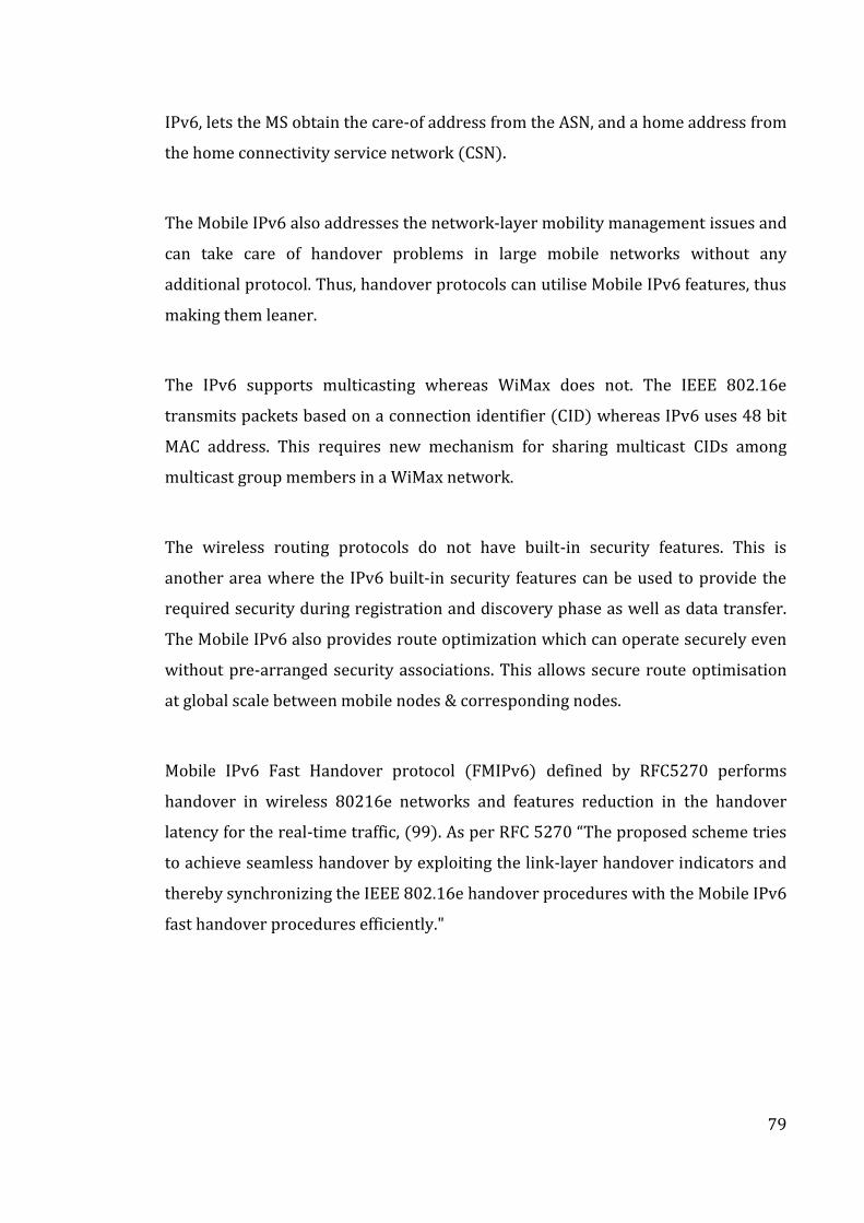
79
IPv6, lets the MS obtain the care-of address from the ASN, and a home address from
the home connectivity service network (CSN).
The Mobile IPv6 also addresses the network-layer mobility management issues and
can take care of handover problems in large mobile networks without any
additional protocol. Thus, handover protocols can utilise Mobile IPv6 features, thus
making them leaner.
The IPv6 supports multicasting whereas WiMax does not. The IEEE 802.16e
transmits packets based on a connection identifier (CID) whereas IPv6 uses 48 bit
MAC address. This requires new mechanism for sharing multicast CIDs among
multicast group members in a WiMax network.
The wireless routing protocols do not have built-in security features. This is
another area where the IPv6 built-in security features can be used to provide the
required security during registration and discovery phase as well as data transfer.
The Mobile IPv6 also provides route optimization which can operate securely even
without pre-arranged security associations. This allows secure route optimisation
at global scale between mobile nodes & corresponding nodes.
Mobile IPv6 Fast Handover protocol (FMIPv6) defined by RFC5270 performs
handover in wireless 80216e networks and features reduction in the handover
latency for the real-time traffic, (99). As per RFC 5270 “The proposed scheme tries
to achieve seamless handover by exploiting the link-layer handover indicators and
thereby synchronizing the IEEE 802.16e handover procedures with the Mobile IPv6
fast handover procedures efficiently."
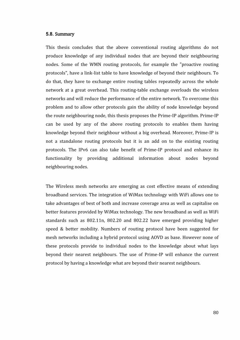
80
5.8. Summary
This thesis concludes that the above conventional routing algorithms do not
produce knowledge of any individual nodes that are beyond their neighbouring
nodes. Some of the WMN routing protocols, for example the "proactive routing
protocols", have a link-list table to have knowledge of beyond their neighbours. To
do that, they have to exchange entire routing tables repeatedly across the whole
network at a great overhead. This routing-table exchange overloads the wireless
networks and will reduce the performance of the entire network. To overcome this
problem and to allow other protocols gain the ability of node knowledge beyond
the route neighbouring node, this thesis proposes the Prime-IP algorithm. Prime-IP
can be used by any of the above routing protocols to enables them having
knowledge beyond their neighbour without a big overhead. Moreover, Prime-IP is
not a standalone routing protocols but it is an add on to the existing routing
protocols. The IPv6 can also take benefit of Prime-IP protocol and enhance its
functionality by providing additional information about nodes beyond
neighbouring nodes.
The Wireless mesh networks are emerging as cost effective means of extending
broadband services. The integration of WiMax technology with WiFi allows one to
take advantages of best of both and increase coverage area as well as capitalise on
better features provided by WiMax technology. The new broadband as well as WiFi
standards such as 802.11n, 802.20 and 802.22 have emerged providing higher
speed & better mobility. Numbers of routing protocol have been suggested for
mesh networks including a hybrid protocol using AOVD as base. However none of
these protocols provide to individual nodes to the knowledge about what lays
beyond their nearest neighbours. The use of Prime-IP will enhance the current
protocol by having a knowledge what are beyond their nearest neighbours.
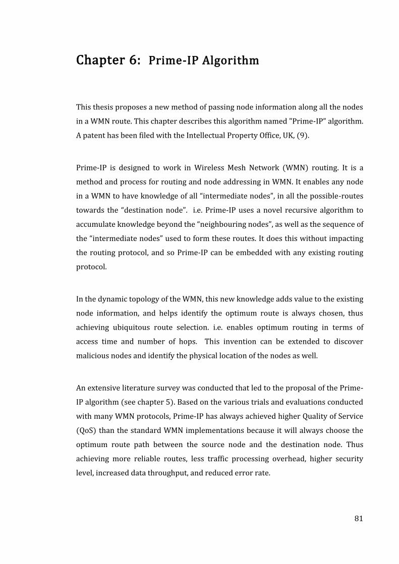
81
Chapter 6: Prime-IP Algorithm
This thesis proposes a new method of passing node information along all the nodes
in a WMN route. This chapter describes this algorithm named "Prime-IP” algorithm.
A patent has been filed with the Intellectual Property Office, UK, (9).
Prime-IP is designed to work in Wireless Mesh Network (WMN) routing. It is a
method and process for routing and node addressing in WMN. It enables any node
in a WMN to have knowledge of all “intermediate nodes”, in all the possible-routes
towards the “destination node”. i.e. Prime-IP uses a novel recursive algorithm to
accumulate knowledge beyond the “neighbouring nodes”, as well as the sequence of
the “intermediate nodes” used to form these routes. It does this without impacting
the routing protocol, and so Prime-IP can be embedded with any existing routing
protocol.
In the dynamic topology of the WMN, this new knowledge adds value to the existing
node information, and helps identify the optimum route is always chosen, thus
achieving ubiquitous route selection. i.e. enables optimum routing in terms of
access time and number of hops. This invention can be extended to discover
malicious nodes and identify the physical location of the nodes as well.
An extensive literature survey was conducted that led to the proposal of the Prime-
IP algorithm (see chapter 5). Based on the various trials and evaluations conducted
with many WMN protocols, Prime-IP has always achieved higher Quality of Service
(QoS) than the standard WMN implementations because it will always choose the
optimum route path between the source node and the destination node. Thus
achieving more reliable routes, less traffic processing overhead, higher security
level, increased data throughput, and reduced error rate.
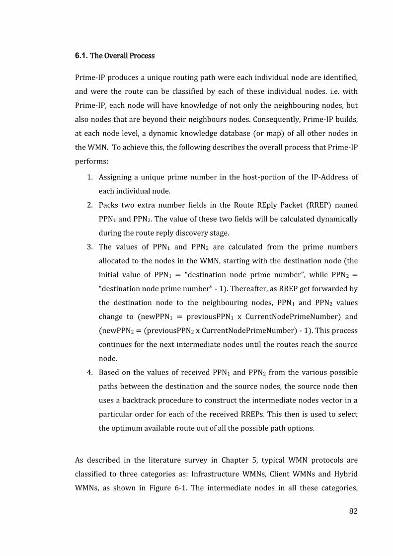
82
6.1. The Overall Process
Prime-IP produces a unique routing path were each individual node are identified,
and were the route can be classified by each of these individual nodes. i.e. with
Prime-IP, each node will have knowledge of not only the neighbouring nodes, but
also nodes that are beyond their neighbours nodes. Consequently, Prime-IP builds,
at each node level, a dynamic knowledge database (or map) of all other nodes in
the WMN. To achieve this, the following describes the overall process that Prime-IP
performs:
1. Assigning a unique prime number in the host-portion of the IP-Address of
each individual node.
2. Packs two extra number fields in the Route REply Packet (RREP) named
PPN1 and PPN2. The value of these two fields will be calculated dynamically
during the route reply discovery stage.
3. The values of PPN1 and PPN2 are calculated from the prime numbers
allocated to the nodes in the WMN, starting with the destination node (the
initial value of PPN1 = “destination node prime number”, while PPN2 =
“destination node prime number” - 1). Thereafter, as RREP get forwarded by
the destination node to the neighbouring nodes, PPN1 and PPN2 values
change to (newPPN1 = previousPPN1 x CurrentNodePrimeNumber) and
(newPPN2 = (previousPPN2 x CurrentNodePrimeNumber) - 1). This process
continues for the next intermediate nodes until the routes reach the source
node.
4. Based on the values of received PPN1 and PPN2 from the various possible
paths between the destination and the source nodes, the source node then
uses a backtrack procedure to construct the intermediate nodes vector in a
particular order for each of the received RREPs. This then is used to select
the optimum available route out of all the possible path options.
As described in the literature survey in Chapter 5, typical WMN protocols are
classified to three categories as: Infrastructure WMNs, Client WMNs and Hybrid
WMNs, as shown in Figure 6-1. The intermediate nodes in all these categories,
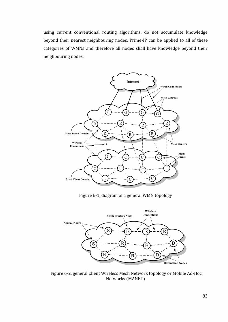
83
using current conventional routing algorithms, do not accumulate knowledge
beyond their nearest neighbouring nodes. Prime-IP can be applied to all of these
categories of WMNs and therefore all nodes shall have knowledge beyond their
neighbouring nodes.
Internet
G G GG
R RR
R R
R
R
C C CC
C CC
C C
C
C
Mesh Route Domain
Mesh Client Domain
Mesh Gateway
Mesh Routers
Mesh
Clients
Wired Connections
Wireless
Connections
Figure 6-1, diagram of a general WMN topology
S R RR
S RR
R R
D
D
Source Nodes
Wireless
Connections
Destination Nodes
Mesh Routers Node
Figure 6-2, general Client Wireless Mesh Network topology or Mobile Ad-Hoc Networks (MANET)
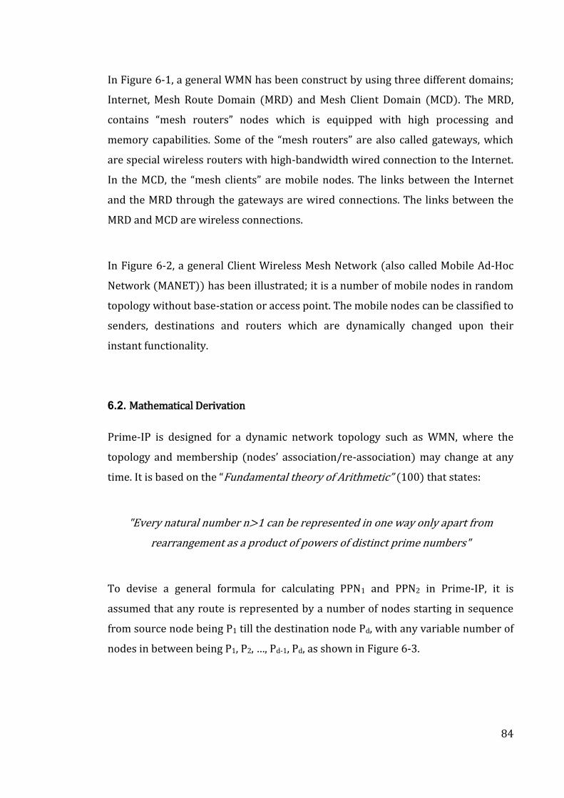
84
In Figure 6-1, a general WMN has been construct by using three different domains;
Internet, Mesh Route Domain (MRD) and Mesh Client Domain (MCD). The MRD,
contains “mesh routers” nodes which is equipped with high processing and
memory capabilities. Some of the “mesh routers” are also called gateways, which
are special wireless routers with high-bandwidth wired connection to the Internet.
In the MCD, the “mesh clients” are mobile nodes. The links between the Internet
and the MRD through the gateways are wired connections. The links between the
MRD and MCD are wireless connections.
In Figure 6-2, a general Client Wireless Mesh Network (also called Mobile Ad-Hoc
Network (MANET)) has been illustrated; it is a number of mobile nodes in random
topology without base-station or access point. The mobile nodes can be classified to
senders, destinations and routers which are dynamically changed upon their
instant functionality.
6.2. Mathematical Derivation
Prime-IP is designed for a dynamic network topology such as WMN, where the
topology and membership nodes’ association/re-association) may change at any
time. It is based on the “Fundamental theory of Arithmetic” (100) that states:
"Every natural number n>1 can be represented in one way only apart from
rearrangement as a product of powers of distinct prime numbers"
To devise a general formula for calculating PPN1 and PPN2 in Prime-IP, it is
assumed that any route is represented by a number of nodes starting in sequence
from source node being P1 till the destination node Pd, with any variable number of
nodes in between being P1, P2, …, Pd-1, Pd, as shown in Figure 6-3.
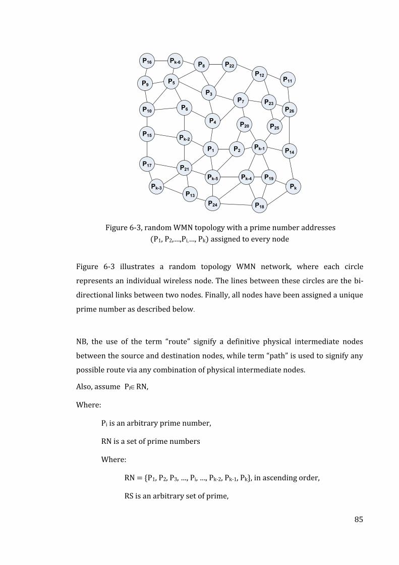
85
P15 Pk-2
P21P17
P1
P24
P13
Pk-3
Pk-5
P2
Pk-4
Pk-1
P18
P19
P14
Pk
P16 Pk-6
P5P9
P8
P4
P6P10
P3
P22
P7
P12
P20
P23
P11
P26
P25
Figure 6-3, random WMN topology with a prime number addresses
(P1, P2,…,Pi,…, Pk) assigned to every node
Figure 6-3 illustrates a random topology WMN network, where each circle
represents an individual wireless node. The lines between these circles are the bi-
directional links between two nodes. Finally, all nodes have been assigned a unique
prime number as described below.
NB, the use of the term “route” signify a definitive physical intermediate nodes
between the source and destination nodes, while term “path” is used to signify any
possible route via any combination of physical intermediate nodes.
Also, assume PiRN,
Where:
Pi is an arbitrary prime number,
RN is a set of prime numbers
Where:
RN = {P1, P2, P3, …, Pi, …, Pk-2, Pk-1, Pk}, in ascending order,
RS is an arbitrary set of prime,
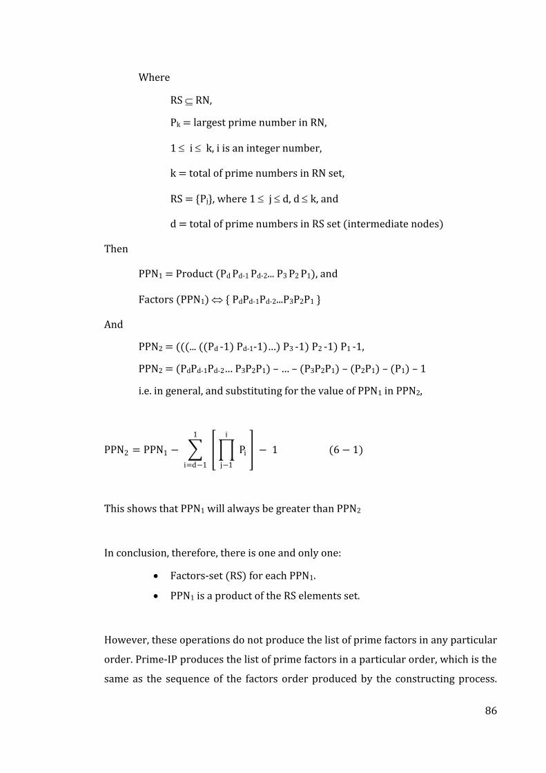
86
Where
RS RN,
Pk = largest prime number in RN,
1 i k, i is an integer number,
k = total of prime numbers in RN set,
RS = {Pj}, where 1 j d, d k, and
d = total of prime numbers in RS set (intermediate nodes)
Then
PPN1 = Product (Pd Pd-1 Pd-2... P3 P2 P1), and
Factors (PPN1) { PdPd-1Pd-2...P3P2P1 }
And
PPN2 = (((... ((Pd -1) Pd-1-1)…) P3 -1) P2 -1) P1 -1,
PPN2 = (PdPd-1Pd-2… P3P2P1) – … – (P3P2P1) – (P2P1) – (P1) – 1
i.e. in general, and substituting for the value of PPN1 in PPN2,
PPN2 = PPN1 − Pi
i
j−1
1
i=d−1
− 1 (6 − 1)
This shows that PPN1 will always be greater than PPN2
In conclusion, therefore, there is one and only one:
Factors-set (RS) for each PPN1.
PPN1 is a product of the RS elements set.
However, these operations do not produce the list of prime factors in any particular
order. Prime-IP produces the list of prime factors in a particular order, which is the
same as the sequence of the factors order produced by the constructing process.
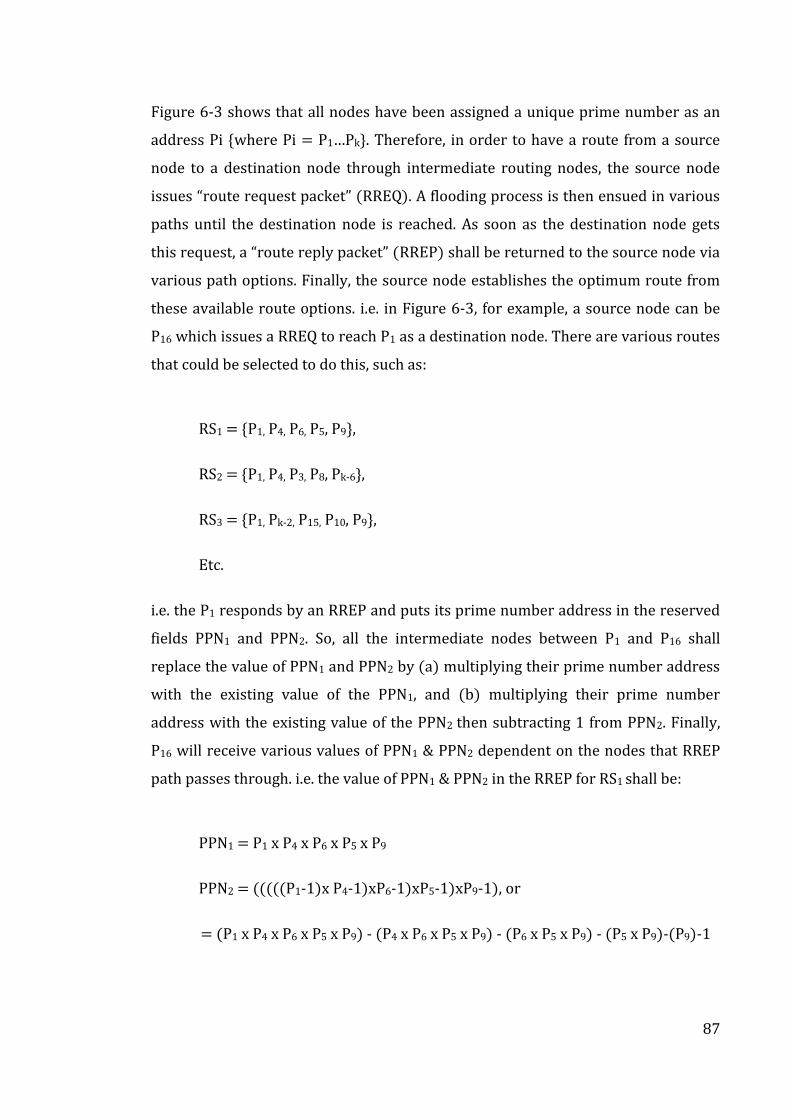
87
Figure 6-3 shows that all nodes have been assigned a unique prime number as an
address Pi {where Pi = P1…Pk}. Therefore, in order to have a route from a source
node to a destination node through intermediate routing nodes, the source node
issues “route request packet” RREQ). A flooding process is then ensued in various
paths until the destination node is reached. As soon as the destination node gets
this request, a “route reply packet” RREP) shall be returned to the source node via
various path options. Finally, the source node establishes the optimum route from
these available route options. i.e. in Figure 6-3, for example, a source node can be
P16 which issues a RREQ to reach P1 as a destination node. There are various routes
that could be selected to do this, such as:
RS1 = {P1, P4, P6, P5, P9},
RS2 = {P1, P4, P3, P8, Pk-6},
RS3 = {P1, Pk-2, P15, P10, P9},
Etc.
i.e. the P1 responds by an RREP and puts its prime number address in the reserved
fields PPN1 and PPN2. So, all the intermediate nodes between P1 and P16 shall
replace the value of PPN1 and PPN2 by (a) multiplying their prime number address
with the existing value of the PPN1, and (b) multiplying their prime number
address with the existing value of the PPN2 then subtracting 1 from PPN2. Finally,
P16 will receive various values of PPN1 & PPN2 dependent on the nodes that RREP
path passes through. i.e. the value of PPN1 & PPN2 in the RREP for RS1 shall be:
PPN1 = P1 x P4 x P6 x P5 x P9
PPN2 = (((((P1-1)x P4-1)xP6-1)xP5-1)xP9-1), or
= (P1 x P4 x P6 x P5 x P9) - (P4 x P6 x P5 x P9) - (P6 x P5 x P9) - (P5 x P9)-(P9)-1
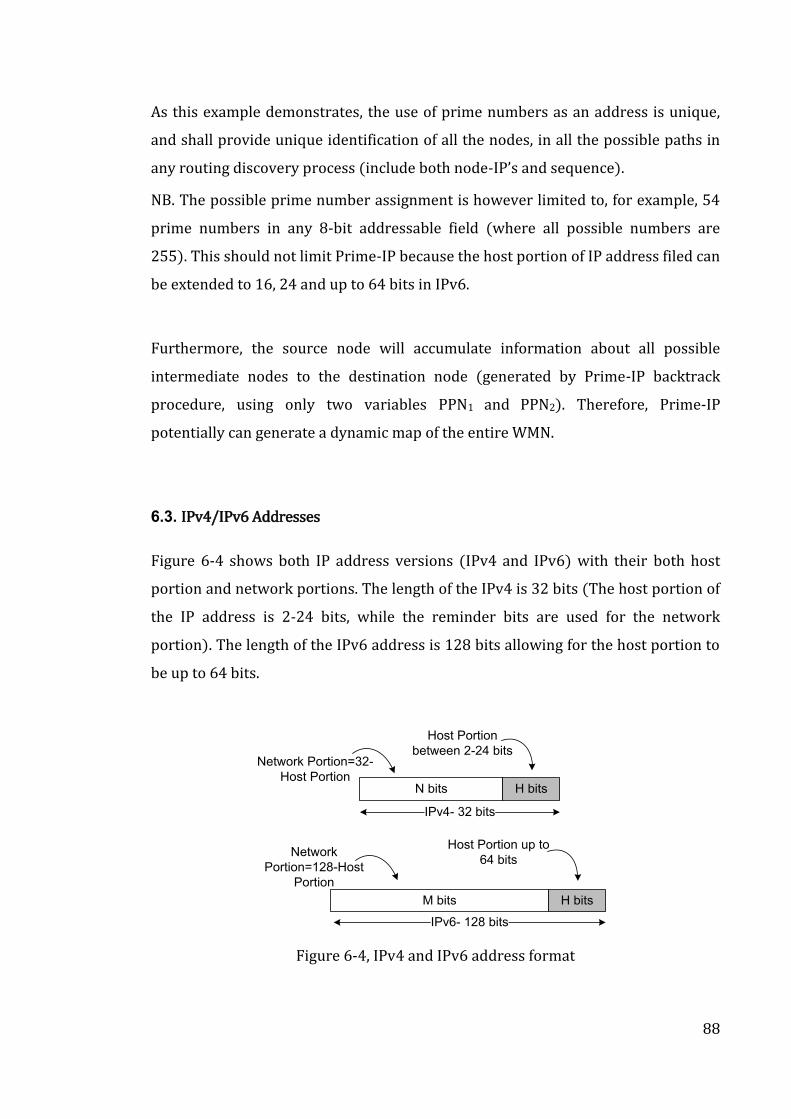
88
As this example demonstrates, the use of prime numbers as an address is unique,
and shall provide unique identification of all the nodes, in all the possible paths in
any routing discovery process (include both node-IP’s and sequence).
NB. The possible prime number assignment is however limited to, for example, 54
prime numbers in any 8-bit addressable field (where all possible numbers are
255). This should not limit Prime-IP because the host portion of IP address filed can
be extended to 16, 24 and up to 64 bits in IPv6.
Furthermore, the source node will accumulate information about all possible
intermediate nodes to the destination node (generated by Prime-IP backtrack
procedure, using only two variables PPN1 and PPN2). Therefore, Prime-IP
potentially can generate a dynamic map of the entire WMN.
6.3. IPv4/IPv6 Addresses
Figure 6-4 shows both IP address versions (IPv4 and IPv6) with their both host
portion and network portions. The length of the IPv4 is 32 bits (The host portion of
the IP address is 2-24 bits, while the reminder bits are used for the network
portion). The length of the IPv6 address is 128 bits allowing for the host portion to
be up to 64 bits.
N bits H bits
IPv4- 32 bits
M bits H bits
IPv6- 128 bits
Host Portion
between 2-24 bitsNetwork Portion=32-
Host Portion
Host Portion up to
64 bitsNetwork
Portion=128-Host
Portion
Figure 6-4, IPv4 and IPv6 address format
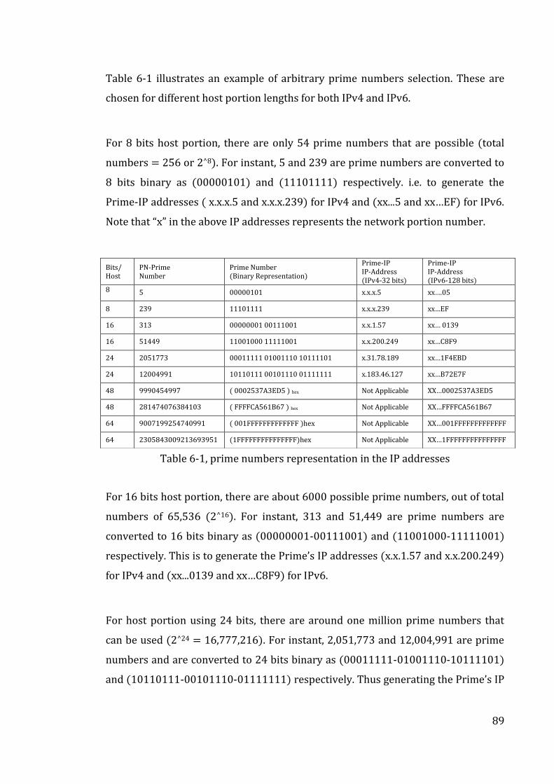
89
Table 6-1 illustrates an example of arbitrary prime numbers selection. These are
chosen for different host portion lengths for both IPv4 and IPv6.
For 8 bits host portion, there are only 54 prime numbers that are possible (total
numbers = 256 or 2^8). For instant, 5 and 239 are prime numbers are converted to
8 bits binary as (00000101) and (11101111) respectively. i.e. to generate the
Prime-IP addresses x.x.x.5 and x.x.x.239) for IPv4 and xx...5 and xx…EF) for IPv6.
Note that “x” in the above IP addresses represents the network portion number.
Table 6-1, prime numbers representation in the IP addresses
For 16 bits host portion, there are about 6000 possible prime numbers, out of total
numbers of 65,536 (2^16). For instant, 313 and 51,449 are prime numbers are
converted to 16 bits binary as (00000001-00111001) and (11001000-11111001)
respectively. This is to generate the Prime’s IP addresses x.x.1.57 and x.x.200.249)
for IPv4 and xx...0139 and xx…C8F9) for IPv6.
For host portion using 24 bits, there are around one million prime numbers that
can be used (2^24 = 16,777,216). For instant, 2,051,773 and 12,004,991 are prime
numbers and are converted to 24 bits binary as (00011111-01001110-10111101)
and (10110111-00101110-01111111) respectively. Thus generating the Prime’s IP
Bits/ Host
PN-Prime Number
Prime Number (Binary Representation)
Prime-IP IP-Address (IPv4-32 bits)
Prime-IP IP-Address (IPv6-128 bits)
8 5 00000101 x.x.x.5 xx….05
8 239 11101111 x.x.x.239 xx…EF
16 313 00000001 00111001 x.x.1.57 xx… 0139
16 51449 11001000 11111001 x.x.200.249 xx…C8F9
24 2051773 00011111 01001110 10111101 x.31.78.189 xx…1F4EBD
24 12004991 10110111 00101110 01111111 x.183.46.127 xx…B72E7F
48 9990454997 ( 0002537A3ED5 ) hex Not Applicable XX…0002537A3ED5
48 281474076384103 ( FFFFCA561B67 ) hex Not Applicable XX…FFFFCA561B67
64 9007199254740991 ( 001FFFFFFFFFFFFF )hex Not Applicable XX…001FFFFFFFFFFFFF
64 2305843009213693951 (1FFFFFFFFFFFFFFF)hex Not Applicable XX…1FFFFFFFFFFFFFFF
90
addresses (x.31.78.189 and x.183.46.127) for IPv4 and (xx...1F4EBD and
xx…B72E7F) for IPv6.
In the host portion of 48 bits, there are around eight trillion prime numbers out of
(2^48) numbers. For instant, 9,990,454,997 and 281,474,076,384,103 are prime
numbers which are converted to 48 bits in hexadecimal as (0002537A3ED5)hex and
(FFFFCA561B67)hex, respectively, to generate the Prime’s IP addresses xx...
0002537A3ED5 and xx… FFFFCA561B67) for IPv6. There is no entry for IPv4 in
Table 6-1 because it is 32 bits length, and so it is not applicable in the case.
For 64 bits host portion, there are around 4*1017 prime numbers out of (2^64). For
instant, 9,007,199,254,740,991 and 2,305,843,009,213,693,951 are prime numbers
which have being converted to 64 bits in hexadecimal as (001FFFFFFFFFFFFF)hex
and (1FFFFFFFFFFFFFFF)hex respectively to generate the Prime- IP addresses
xx...001FFFFFFFFFFFFF and xx…1FFFFFFFFFFFFFFF) for IPv6.
6.4. Backtrack Procedure
For every available route from the source node to the destination node, Prime-IP’s
backtrack procedure generates the vector containing the intermediate node
addresses in a particular order. PPN1 and PPN2 numbers are used as input to the
backtrack procedure. Figure 6-5, Figure 6-6 and
Figure 6-7 show the diagram from Figure 6-3, but with actual prime number
assigned to all node address (P1…Pk), and highlighting 3 route examples.
The “source node” gets a route replay packets containing the PPN1 and PPN2
numbers. As shown in Figure 6-5 and Figure 6-6, two different routes are
highlighted between the source node-71 and the destination node-73.
Figure 6-7 shows a highlighted route between source node-7 and the destination
node-11. Figure 6-8 shows a tree diagram of how the “backtrack procedure” is
applied to determine the track which represents the intermediate nodes vector in
that particular order.
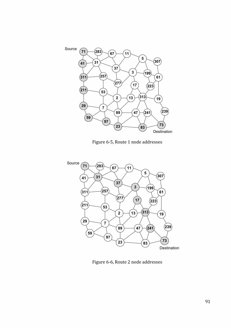
91
21153
729
2
23
9759
89
13
47
313
83
241
19
73
71 283
3141
67
277
257311
37
11
3
5
17
199
307
61
223
239
Source
Destination
Figure 6-5, Route 1 node addresses
21153
729
2
23
9759
89
13
47
313
83
241
19
73
71 283
3141
67
277
257311
37
11
3
5
17
199
307
61
223
239
Source
Destination
Figure 6-6, Route 2 node addresses
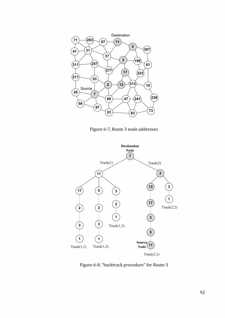
92
21153
729
2
23
9759
89
13
47
313
83
241
19
73
71 283
3141
67
277
257311
37
11
3
5
17
199
307
61
223
239
Source
Destination
Figure 6-7, Route 3 node addresses
7
11 2
13
17
5
11
35
2
3
1
317
2
3
1
2
1
Track(1) Track(2)
Track(1,3)
Track(1,1) Track(1,2)
Track(2,2)
Track(2,1)
1
Destination
Node
Source
Node
3
Figure 6-8, “backtrack procedure” for Route 3
93
Tables Table 6-2,Table 6-3 and Table 6-4 demonstrate the values of PPN1 and PPN2
in the highlighted routes that have been illustrated in Figures Figure 6-5Figure 6-6
and
Figure 6-7 respectively. In each of these examples, the source node gets a set of
PPN1 and PPN2 numbers which is classified as following:
Route 1: shown in Figure 6-5 and Table 6-2:
PPN1 = 622,26,766,372,853,959
PPN2 = 61,363,623,565,807,294
Route 2: shown in Figure 6-6 and Table 6-3 :
PPN1 = 322,120,106,673
PPN2 = 317,689,113,736
Route 3: shown in
Figure 6-7 and Table 6-4:
PPN1 = 72,930
PPN2 = 64,503
After the route reply packet has been received by the source node, the backtrack
procedure will start to generate the vector (RS). Figure 6-9 shows a flowchart of
this procedure, which includes the iterations performed to consider all possibilities
in forming the route vectors.
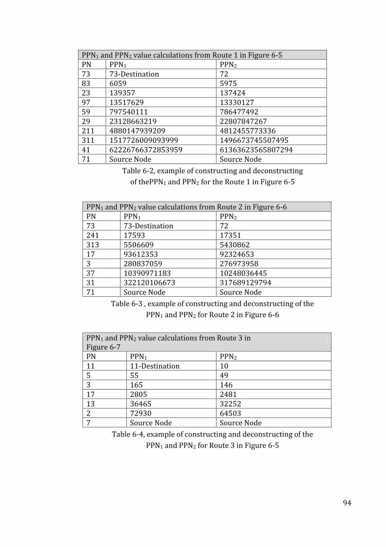
94
PPN1 and PPN2 value calculations from Route 1 in Figure 6-5 PN PPN1 PPN2 73 73-Destination 72 83 6059 5975 23 139357 137424 97 13517629 13330127 59 797540111 786477492 29 23128663219 22807847267 211 4880147939209 4812455773336 311 1517726009093999 1496673745507495 41 62226766372853959 61363623565807294 71 Source Node Source Node
Table 6-2, example of constructing and deconstructing
of thePPN1 and PPN2 for the Route 1 in Figure 6-5
PPN1 and PPN2 value calculations from Route 2 in Figure 6-6 PN PPN1 PPN2 73 73-Destination 72 241 17593 17351 313 5506609 5430862 17 93612353 92324653 3 280837059 276973958 37 10390971183 10248036445 31 322120106673 317689129794 71 Source Node Source Node
Table 6-3 , example of constructing and deconstructing of the
PPN1 and PPN2 for Route 2 in Figure 6-6
PPN1 and PPN2 value calculations from Route 3 in Figure 6-7 PN PPN1 PPN2 11 11-Destination 10 5 55 49 3 165 146 17 2805 2481 13 36465 32252 2 72930 64503 7 Source Node Source Node
Table 6-4, example of constructing and deconstructing of the
PPN1 and PPN2 for Route 3 in Figure 6-5
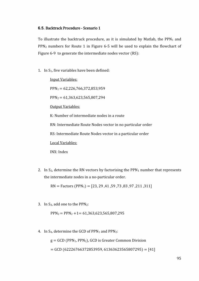
95
6.5. Backtrack Procedure - Scenario 1
To illustrate the backtrack procedure, as it is simulated by Matlab, the PPN1 and
PPN2 numbers for Route 1 in Figure 6-5 will be used to explain the flowchart of
Figure 6-9 to generate the intermediate nodes vector (RS):
1. In S1, five variables have been defined:
Input Variables:
PPN1 = 62,226,766,372,853,959
PPN2 = 61,363,623,565,807,294
Output Variables:
K: Number of intermediate nodes in a route
RN: Intermediate Route Nodes vector in no particular order
RS: Intermediate Route Nodes vector in a particular order
Local Variables:
INX: Index
2. In S2, determine the RN vectors by factorising the PPN1 number that represents
the intermediate nodes in a no-particular order.
RN = Factors (PPN1) = [23, 29 ,41 ,59 ,73 ,83 ,97 ,211 ,311]
3. In S3, add one to the PPN2:
PPN2 = PPN2 +1= 61,363,623,565,807,295
4. In S4, determine the GCD of PPN1 and PPN2:
g = GCD (PPN1, PPN2), GCD is Greater Common Division
= GCD (62226766372853959, 61363623565807295) = [41]
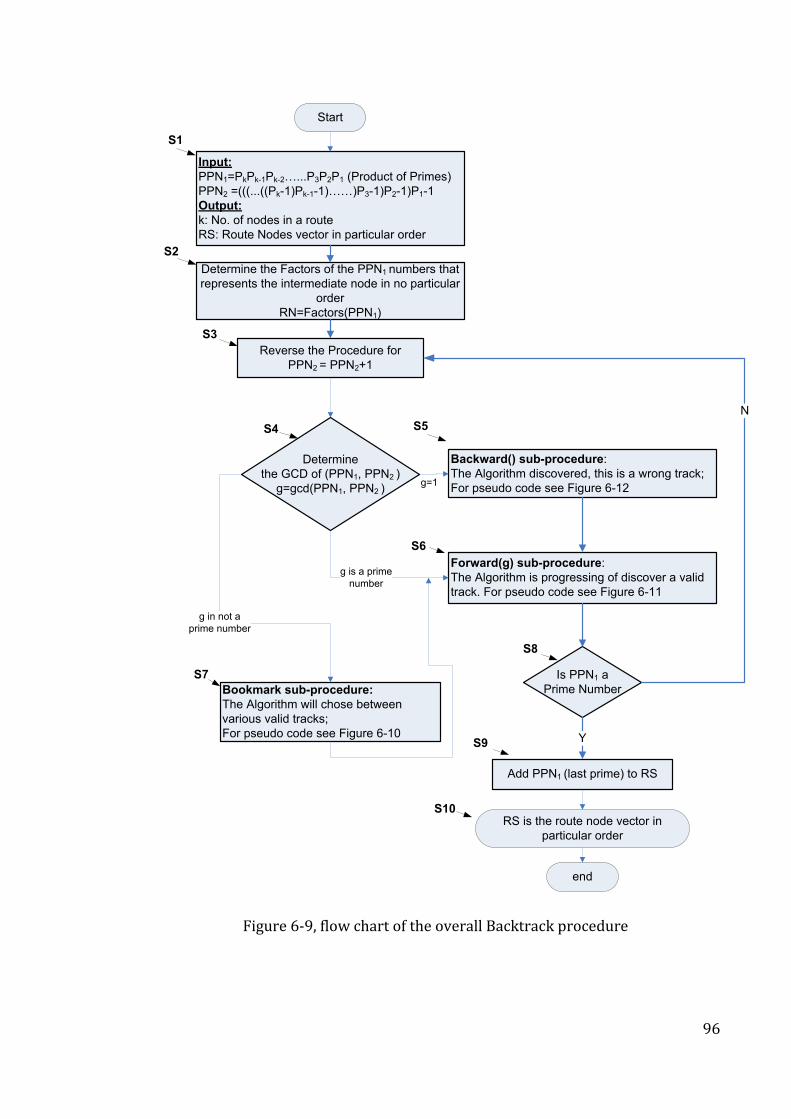
96
Determine the Factors of the PPN1 numbers that
represents the intermediate node in no particular
order
RN=Factors(PPN1)
Reverse the Procedure for
PPN2 = PPN2+1
Is PPN1 a
Prime Number
Add PPN1 (last prime) to RS
Input:
PPN1=PkPk-1Pk-2…...P3P2P1 (Product of Primes)
PPN2 =(((...((Pk-1)Pk-1-1)……)P3-1)P2-1)P1-1
Output:
k: No. of nodes in a route
RS: Route Nodes vector in particular order
Bookmark sub-procedure:
The Algorithm will chose between
various valid tracks;
For pseudo code see Figure 6-10
Backward() sub-procedure:
The Algorithm discovered, this is a wrong track;
For pseudo code see Figure 6-12
Forward(g) sub-procedure:
The Algorithm is progressing of discover a valid
track. For pseudo code see Figure 6-11
Determine
the GCD of (PPN1, PPN2 )
g=gcd(PPN1, PPN2 )
N
Y
S1
S2
S4 S5
S6
S7
S8
S10
Start
g is a prime
number
g in not a
prime number
g=1
S3
S9
end
RS is the route node vector in
particular order
Figure 6-9, flow chart of the overall Backtrack procedure
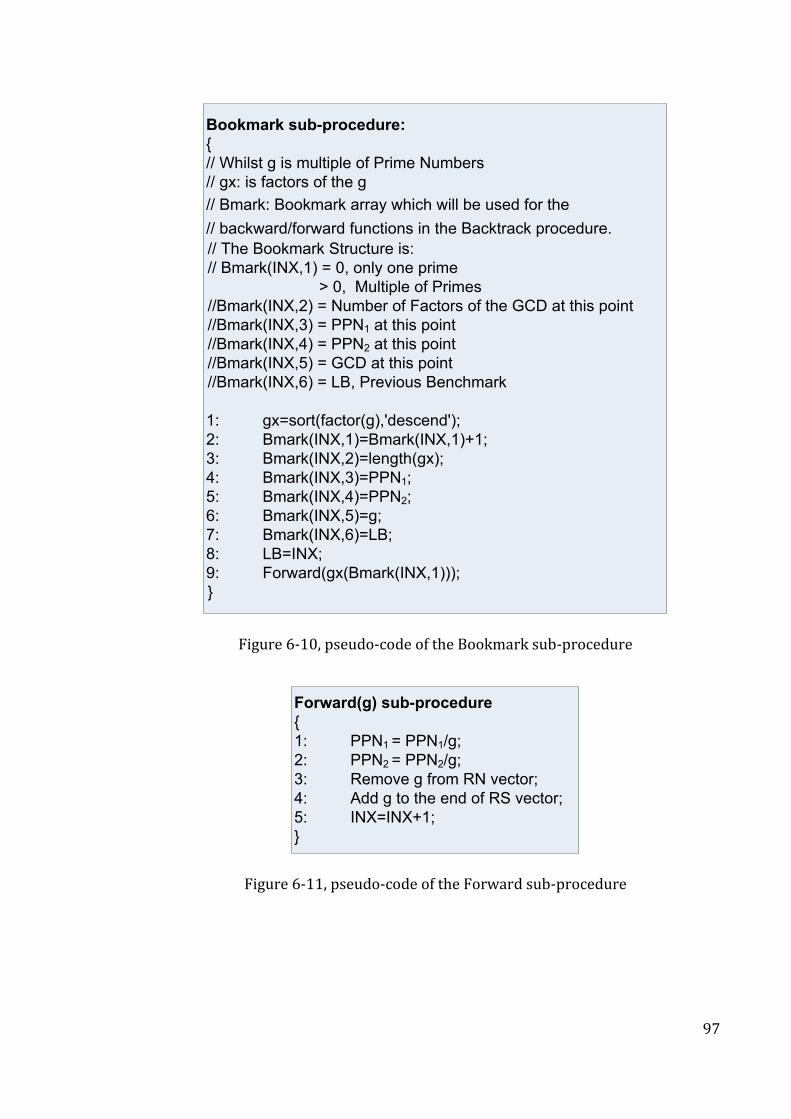
97
Bookmark sub-procedure:
{
// Whilst g is multiple of Prime Numbers
// gx: is factors of the g
// Bmark: Bookmark array which will be used for the
// backward/forward functions in the Backtrack procedure.
// The Bookmark Structure is:
// Bmark(INX,1) = 0, only one prime
> 0, Multiple of Primes
//Bmark(INX,2) = Number of Factors of the GCD at this point
//Bmark(INX,3) = PPN1 at this point
//Bmark(INX,4) = PPN2 at this point
//Bmark(INX,5) = GCD at this point
//Bmark(INX,6) = LB, Previous Benchmark
1: gx=sort(factor(g),'descend');
2: Bmark(INX,1)=Bmark(INX,1)+1;
3: Bmark(INX,2)=length(gx);
4: Bmark(INX,3)=PPN1;
5: Bmark(INX,4)=PPN2;
6: Bmark(INX,5)=g;
7: Bmark(INX,6)=LB;
8: LB=INX;
9: Forward(gx(Bmark(INX,1)));
}
Figure 6-10, pseudo-code of the Bookmark sub-procedure
Forward(g) sub-procedure
{
1: PPN1 = PPN1/g;
2: PPN2 = PPN2/g;
3: Remove g from RN vector;
4: Add g to the end of RS vector;
5: INX=INX+1;
}
Figure 6-11, pseudo-code of the Forward sub-procedure
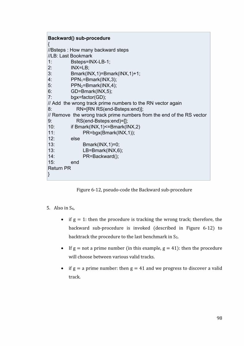
98
Backward() sub-procedure
{
//Bsteps : How many backward steps
//LB: Last Bookmark
1: Bsteps=INX-LB-1;
2: INX=LB;
3: Bmark(INX,1)=Bmark(INX,1)+1;
4: PPN1=Bmark(INX,3);
5: PPN2=Bmark(INX,4);
6: GD=Bmark(INX,5);
7: bgx=factor(GD);
// Add the wrong track prime numbers to the RN vector again
8: RN=[RN RS(end-Bsteps:end)];
// Remove the wrong track prime numbers from the end of the RS vector
9: RS(end-Bsteps:end)=[];
10: if Bmark(INX,1)<=Bmark(INX,2)
11: PR=bgx(Bmark(INX,1));
12: else
13: Bmark(INX,1)=0;
13: LB=Bmark(INX,6);
14: PR=Backward();
15: end
Return PR
}
Figure 6-12, pseudo-code the Backward sub-procedure
5. Also in S4,
if g = 1: then the procedure is tracking the wrong track; therefore, the
backward sub-procedure is invoked (described in Figure 6-12) to
backtrack the procedure to the last benchmark in S5.
If g = not a prime number (in this example, g = 41): then the procedure
will choose between various valid tracks.
if g = a prime number: then g = 41 and we progress to discover a valid
track.
99
6. In S6, the forward sub-procedure is invoked as described in Figure 6-11. This
moves the process forward by calculating the values to discover node-41:
PPN1 = PPN1/g = 62,226,766,372,853,959/41 = 1,517,726,009,093,999
PPN2 = PPN2 /g = 61,363,623,565,807,295/41 = 1,496,673,745,507,495
Remove the first prime number [41] from RN and add it to RS
RN = [23, 29,59 ,73 ,83 ,97 ,211 ,311]
RS = [41], INX = INX+1 = 1
7. In S8, if PPN1 is not a prime number, then go to S3.
8. Repeat (3-7) above as many times as necessary in order to obtain the final RS
that represents all the intermediate route nodes vector in a particular order.
The following is to discover node-311:
PPN2 = PPN2 +1 = 1,496,673,745,507,495+1 = 1,496,673,745,507,496
g = GCS (PPN1, PPN2) = GCD(1517726009093999, 1496673745507496) = [311]
PPN1 = PPN1/g = 1,517,726,009,093,999/311 = 4,880,147,939,209
PPN2 = PPN2 /g = 1,496,673,745,507,496/311 = 4,812,455,773,336
RN = [23, 29, 59, 73, 83, 97, 211]
Remove the prime number [311] from RN and add it to RS. i.e.
RS = [41,311], INX = INX+1 = 2
Again, for node-211:
PPN2 = PPN2 +1 = 4,812,455,773,336+1 = 4,812,455,773,337
g = GCS (PPN1, PPN2) = GCD(4880147939209, 4812455773337) = [211]
PPN1 = PPN1/g = 4,880,147,939,209/211 = 23,128,663,219
PPN2 = PPN2 /g = 4,812,455,773,337/211 = 22,807,847,267
100
RN = [23, 29, 59, 73, 83, 97],
Remove the prime number [211] from RN and add it to RS
RS = [41,311,211], INX = INX+1 = 3
Again for node-29:
PPN2 = PPN2 +1 = 22,807,847,267+1 = 22,807,847,268
g = GCS (PPN1, PPN2) = GCD (23128663219, 22807847268) = [29]
PPN1 = PPN1/g = 23,128,663,219/29 = 797,540,111
PPN2 = PPN2 /g = 22,807,847,268/29 = 786,477,492
RN = [23, 59, 73, 83, 97],
Remove the prime number [29] from RN and add it to RS
RS = [41, 311, 211, 29], INX = INX+1 = 4
Again for node-59:
PPN2 = PPN2 +1= 786,477,492+1= 786,477,493
g= GCS (PPN1, PPN2) = GCD(797540111, 786477493) = [59]
PPN1 = PPN1/g = 797,540,111/59 = 13,517,629
PPN2 = PPN2 /g = 786,477,493/59 = 13,330,127
RN = [23, 73, 83, 97],
Remove the prime number [59] from RN and add it to RS
RS = [41, 311, 211, 29, 59], INX= INX+1= 5
Again node-97:
PPN2 = PPN2 +1 = 13,330,127+1 = 13,330,128
g = GCS (PPN1, PPN2) = GCD(13517629, 13330128) = [97]
101
PPN1 = PPN1/g = 13,517,629/97 = 139,357
PPN2 = PPN2 /g = 13,330,128/97 = 137,424
RN = [23, 73, 83],
Remove the prime number [97] from RN and add it to RS
RS = [41, 311, 211, 29, 59, 97], INX= INX+1= 6
Again, this time for node-23:
PPN2 = PPN2 +1 = 137,424+1 = 137,425
g = GCS (PPN1, PPN2) = GCD(139357, 137425) = [23]
PPN1 = PPN1/g= 139,357/23 = 6,059
PPN2 = PPN2 /g = 137,425/23 = 5,975
RN = [73, 83],
Remove the prime number [23] from RN and add it to RS
RS = [41, 311, 211, 29, 59, 97, 23], INX = INX+1 = 7
Again, finally for node-83:
PPN2 = PPN2 +1 = 5,975+1 = 5,976
g = GCS (PPN1, PPN2) = GCD(6059, 5976) = [83]
PPN1 = PPN1/g = 6,059/83 = 73
PPN2 = PPN2 /g = 5,976/83 = 72
RN = [73]
Remove the first prime number [83] from RN and add it to RS
RS = [41, 311, 211, 29, 59, 97, 23, 83], INX = INX+1 = 8
9. In S8, if PPN1 is a prime number then this is also the destination node, (in this
example, PPN1 = 73), and so go to S9
102
10. In S9, add (73) to RS = [41, 311, 211, 29, 59, 97, 23, 83, 73]
11. In S10, Finally, RS represents the highlighted route in Figure 6-5 and Table 6-2 in
this particular order.
6.6. Backtrack Procedure – Scenario 2
To illustrate the backtrack procedure further, as it is simulated in Matlab, the PPN1
and PPN2 numbers for Route 3 in
Figure 6-7 and Table 6-4 will be used to explain the flowchart of Figure 6-9, but
when the backward-sub-procedure is also invoked, as follows:
1. S1, 5 variables have been defined:
Input Variables:
PPN1 = 72,930
PPN2 = 64,503
Output Variables:
k: Number of intermediate nodes in a route
RN: Intermediate Route Nodes vector in no-particular order
RS: Intermediate Route Nodes vector in particular order
Local Variables:
INX: Index
2. S2, determines the RN vectors by factorising the PPN1 number that represents
the intermediate nodes in no-particular order.
RN = Factors (PPN1) = [2, 3, 5, 11, 13, 17]
103
3. S3, add one to PPN2:
PPN2 = PPN2 +1= 64,504
4. S4, determine the GCD of PPN1 and PPN2:
g = GCS (PPN1, PPN2) = GCD(72930, 64504) = [22]
if g = 1: then the procedure is tracking the wrong track; therefore,
the backward sub-procedure is invoked (described in Figure 6-12) to
backtrack the procedure to the last benchmark in S5.
if g is a prime number: No
If g = not a prime number (in this example, g = 22): then the
procedure will choose between various valid tracks, then, S7.
5. S7 (more details in Figure 6-10), Bookmark Sub-procedure,
gx: Factors of g in descending order ( g is not prime number).
Bmark: Bookmark array used for the forward and backward sub-procedures as
described Figure 6-11 and Figure 6-12.
The Bookmark Structure is:
Bmark(INX,1) = Branch :0 only one prime: ith Multiple of (n-1) prime
number
Bmark(INX,2) = Number of Factors of the GCD at this point (number of
branches)
Bmark(INX,3) = PPN1 at this point
Bmark(INX,4) = PPN2 at this point
Bmark(INX,5) = GCD at this point
Bmark(INX,6) = LB is the Previous Bookmark
104
Figure 6-8 illustrates the behaviour of the backtrack procedure showing “depth-
first search” algorithm when in a tree structure). Prime-IP assigns a bookmark
(Bmark array) for every branch, when more than one track is possible. For instant,
at this point, gx = factors (22) = [11, 2] in descending order. The procedure shall
choose between two tracks, either [11] or [2]. While gx vector has been sorted in
descending order, selecting the prime number will also be in descending order. As
shown in Figure 6-8, node-11 is selected as the next node is track(1). If the
procedure discovers that track(1) is the wrong track selection, then node-2 shall be
selected as a next node in track(2).
Bmark(1,1) = 1, track(1)
Bmark(1,2) = 2, represents the number of various valid tracks at this
bookmark point
Bmark(1,3) = 72,930, PPN1 at this point
Bmark(1,4) = 64,504, PPN2 at this point
Bmark(1,5) = 22, g at this point
Bmark(1,6) = 1, LB represents a Previous Bookmark
Forward(gx(Bmark(1,1))) Forward[11], move the procedure forward.
6. S6, the forward sub-procedure is invoked as described in Figure 6-11. This
moves the process forward by calculating the values to discover node-11
PPN1 = PPN1/g = 72,930/11 = 6,630
PPN2 = PPN2/g = 64,504/11 = 5,864
RN = [2, 3,5,13, 17]
Remove the prime number [11] from RN and add it to RS
RS = [11], INX = INX+1 = 2
7. S8, if PPN1 is not a prime number: PPN1 = 6,630.
105
8. S3, add one to the PPN2: PPN2 = PPN2 +1 = 5,865
9. S4, determine the GCD of PPN1 and PPN2:
g = GCS (PPN1, PPN2) = GCD(6630, 5865) = [255]
If g is not = 1 g= 255
if g is not a prime number: g= 255, then S7
10. S7, this is the start of the “Bookmark Sub-procedure”, as shown in Figure 6-10.
At this point, gx = factors (255) = [17, 5, 3]. The process wants to find the right
track by performing depth-first search. The procedure will consequently test the
following tracks: track(1,1), track(1,2) and track(1,3). Figure 6-8 shows the
possible three tracks:
Selecting [17] as a next node is track (1, 1).
Selecting [5] as a next node is track (1, 2).
Selecting [3] as a next node is track (1, 3).
11. Next, the process moves forward following track (1, 1) in order to find all the
intermediate nodes in a particular order. Once S4 detects that the process is in a
wrong track (g = 1), the backtrack procedure will stop and chooses the next
track (e.g. track (1, 2)). Figure 6-10 and Figure 6-8 illustrates the testing of this
track as in the following steps:
Bmark(2,1) = 1, track(1,1)
Bmark(2,2) = 3, represents the number of various valid tracks at this
bookmark point
Bmark(2,3) = 6,630, PPN1 at this point
Bmark(2,4) = 5,865, PPN2 at this point
Bmark(2,5) = 255, g at this point
Bmark(2,6) = 1, LB represents a Previous Bookmark
Forward(gx(Bmark(2,1))) Forward[17], move the procedure forward
106
12. Move forward in the track (1, 2) in order to find the intermediate node in
particular order. Once S4 detects that is a wrong track (g = 1 is true), backtrack
procedure will stop and undertake the next track (e.g. track (1, 3)). Figure 6-8
and Figure 6-10 illustrates the testing of the track and how the sub-procedures
behaviours will be.
Bmark(2,1) = 2, track(1,2)
Bmark(2,2) = 3, represents the number of various valid tracks at this
bookmark point
Bmark(2,3) = 6,630, PPN1 at this point
Bmark(2,4) = 5,865, PPN2 at this point
Bmark(2,5) = 255, g at this point
Bmark(2,6) = 1, LB represents a Previous Bookmark
Forward(gx(Bmark(2,1))) Forward[5], move the procedure forward
13. Move forward in the track (1,3) in order to find the intermediate node in
particular order. Once S4 detects that is a wrong track (g = 1 is true), backtrack
procedure will stop and undertake a backward track (track(1)), because it is
the last track at this bookmark. Figure 6-10 and Figure 6-8 illustrates the testing
of the track and how the sub-procedures behaviours will be.
Bmark(2,1) = 3, track(1,3)
Bmark(2,2) = 3, represents the number of various valid tracks at this
bookmark point
Bmark(2,3) = 6,630, PPN1 at this point
Bmark(2,4) = 5,865, PPN2 at this point
Bmark(2,5) = 255, g at this point
Bmark(2,6) = 1, LB represents a Previous Bookmark
Forward(gx(Bmark(2,1))) Forward[3], move the procedure forward
107
14. In Figure 6-8, Now that the GCD of (PPN1, PPN2) is equal to one in all track(1)
branches, i.e. the procedure decides it is the wrong track, and so chooses to
progress along track(2). i.e. the right track will never give this result (GCD= 1)
in S4, because at S8 the PPN1 will be tested whether it is a prime number or not.
If it is a prime number, then the backtrack procedure progress in the right track
and it knows that this is the last prime number “destination node”). However,
if the PPN1, in S8, is not a prime number, then the procedure will move forward.
At this point, there is no indication if it is following a wrong or correct track,
until S4 will test is reached again
15. The backtrack procedure will now chose the next possible track as follows, in
this example, it is track(2):
Bmark(1,1) = 2, track(2)
Bmark(1,2) = 2, represents the number of various valid tracks at this
bookmark point
Bmark(1,3) = 72,930, PPN1 at this point
Bmark(1,4) = 64,504, PPN2 at this point
Bmark(1,5) = 22, g at this point
Bmark(1,6) = 1, LB represents a Previous Bookmark
Forward(gx(Bmark(1,1))) Forward[2], move the procedure forward.
16. S6, the forward sub-procedure Figure 6-11 moves forward by the following
calculations:
PPN1 = PPN1/g = 72,930/2 = 36,465
PPN2 = PPN2 /g = 64,504/2 = 32,252
RN = [2, 3,5,13, 17]
Remove the prime number [2] from RN and add it to RS
RS = [2], INX = INX+1 = 2
108
17. S8, if PPN1 is prime: No, PPN1 = 36,465.
18. S3, add one to the PPN2: PPN2 = PPN2 +1 = 32,253
19. S4, determine the GCD of PPN1 and PPN2:
g = GCS (PPN1, PPN2) = GCD(36465, 32253) = [39]
20. In S4,
If g = 1 NO, (g= 39).
if g is a prime number: No, g = 39,
if g is not a prime number:, g = 39, then S7
21. S7 the Bookmark Sub-procedure and as shown in Figure 6-10,
At this point, gx= factors (39) = [13, 3]. The procedure will consequently test the
following tracks: track(2,1) and track(2,2) . Figure 6-8 shows the procedure that
should have chosen between two tracks.
Selecting [13] as a next node is track (2, 1).
Selecting [3] as a next node is track (2, 2).
22. The procedure should have chosen between two tracks, track(2,1) or track(2,2)
while gx vector has been sorted in descending order, selecting the prime
number will be in descending order also. As shown in Figure 6-8, selecting [13]
as a next node is track(2,1) while selecting [3] as a next node is track(2,2) if the
first track(2,1) is wrong.
23. S6, the forward sub-procedure Figure 6-11 moves forward by doing these
calculations:
109
PPN1 = PPN1/g= 36,465/13 = 2,805
PPN2 = PPN2 /g = 32,253/13 = 2,481
RN = [3, 5, 13, 17]
Remove the prime number [13] from RN and add it to RS
RS = [2, 13], INX = INX+1 = 3
24. In S8, if PPN1 is prime: No, PPN1= 2,805.
25. In S3, add one to the PPN2: PPN2 = PPN2 +1 = 2,482
26. In S4, determine the GCD of PPN1 and PPN2:
g = GCS (PPN1, PPN2) = GCD(2805, 2482) = [17]
27. In S4,
If g = 1 NO, (g= 17).
if g is not a prime number, (g = 17).
if g is a prime number: Yes, g = 17,then S6
28. In S6, the forward sub-procedure, Figure 6-11, moves forward by doing these
calculations:
PPN1 = PPN1/g = 2,805/17 = 165
PPN2 = PPN2 /g = 2,482/17 = 146
RN = [3, 5, 17]
Remove the prime number [17] from RN and add it to RS
RS = [2, 13, 17], INX = INX+1 = 4
110
29. Repeat above steps many times in order to get the final RS that represents
Intermediate Route Nodes vector in particular order
PPN1 = PPN1/g = 165/3 = 55
PPN2 = PPN2 /g = 147/3 = 49
RN = [3, 5]
Remove the prime number [3] from RN and add it to RS
RS = [2, 13, 17, 3], INX = INX+1 = 5
30. Repeat it again,
PPN1 = PPN1/g= 55/5 = 11
PPN2 = PPN2 /g = 50/5 = 10
RN = [5]
Remove the prime number [5] from RN and add it to RS
RS = [2, 13, 17, 3, 5], INX = INX+1 = 6
31. In S8, if PPN1 prime number, YES PPN1 = 11,
32. In S9, add [11] to RS = [2, 13, 17, 3, 5, 11],
33. In S10, RS represents the highlighted route in
34. Figure 6-7 and Table 6-4 in particular order.
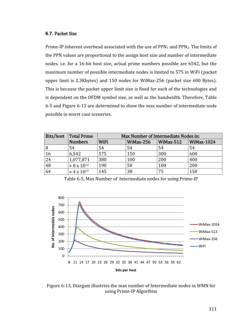
111
6.7. Packet Size
Prime-IP inherent overhead associated with the use of PPN1 and PPN2. The limits of
the PPN values are proportional to the assign host size and number of intermediate
nodes. i.e. for a 16-bit host size, actual prime numbers possible are 6542, but the
maximum number of possible intermediate nodes is limited to 575 in WiFi (packet
upper limit is 2.3Kbytes) and 150 nodes for WiMax-256 (packet size 600 Bytes).
This is because the packet upper limit size is fixed for each of the technologies and
is dependent on the OFDM symbol size, as well as the bandwidth. Therefore, Table
6-5 and Figure 6-13 are determined to show the max number of intermediate node
possible in worst case sceneries.
Bits/host Total Prime Numbers
Max Number of Intermediate Nodes in: WiFi WiMax-256 WiMax-512 WiMax-1024
8 54 54 54 54 54 16 6,542 575 150 300 600 24 1,077,871 380 100 200 400 48 8 x 10¹² 190 50 100 200
64 4 x 10¹⁷ 145 38 75 150
Table 6-5, Max Number of Intermediate nodes for using Prime-IP
Figure 6-13, Diargam illustrtes the max number of Intermediate nodes in WMN for using Prime-IP Algorthim
0
100
200
300
400
500
600
700
800
8 11 14 17 20 23 26 29 32 35 38 41 44 47 50 53 56 59 62
No
. of
Inte
rme
dai
s n
od
es
bits per host
WiMax-1024
WiMax-512
WiMax-256
WiFi
112
6.8. Delay Calculations
Further to the packet size limitation described in section 6.7, the delay associated
with calculation of PPN1 and PPN2 during the RREP is equal to 10 sec for the worst
case. The 10 sec is due to these PPN1 and PPN2 binary-multiplication operation
(i.e. bits shifting + addition). i.e. the number of operations to multiply two binary
numbers with N1 and N2 bits are N1 Shifting + N2 Additions. Therefore, for the
worst case scenario:
Max Bits/host = 64 bits, (see Table 6-5).
Max Number of intermediate nodes = 750 nodes, (see Figure 6-13).
Max Packet size = 2600 Bytes, (IEEE Standard).
The length of PPN1 and the length of PPN2 are approximately equal, and the
maximum size is equal to 1300 Bytes (10400 bits). Therefore, the number of
operations at each node to generate the new PPN1 and the new PPN2 are:
1. newPPN1 = previousPPN1 x CurrentNodePrimeNumber
= 10400 shifting +64 additions = 10464 operations
2. newPPN2 = previousPPN2 x CurrentNodePrimeNumber - 1
= 10400 shifting +65 additions = 10465 operations
This results in a total number of operations = 10464 +10465 = 20929. Based on
various trials, the average execution time for this task was 5sec, with a worst case
delay of 10 sec.
6.9. Summary:
To demonstrate and prove Prime-IP, extensive variations of node scenarios was
studied. This chapter highlighted some of these example scenarios. The novelty
claims made are focused on using “prime numbers” to be the address of the host
portion of node IP and accumulating “node knowledge” of the entire WMN. The
113
resultant “Prime-IP” claims have also been proved mathematically and work for
multihop dynamic topology WMNs.
The following is a summary of the claims made for the novelties in Prime-IP:
1. This algorithm, named “Prime-IP”, is designed to uniquely identify a path in
a Wireless Mesh Networks-WMN, without impacting the routing protocol.
2. Prime-IP is designed to allow each individual node to uniquely identify a
path based on the node’s location within the mesh.
3. The host portion of any Node’s IP address is assigned a unique prime
number.
4. Prime-IP is designed to detect, and survive-the-loss-of, any deactivated
nodes in the route.
5. Further to point 2, and upon a “source node” issue a request to discover a
route to a “destination node”, then, route reply packets received by the
“source node” shall contain full path knowledge about their routes.
6. The route reply packet shall have two extra fields appended to the existing
packet format.
7. Further to point 6, these two new fields will contain a value related to the
“Product of Prime Numbers”, see point 3, and these two fields shall be
named PPN1 and PPN2.
8. PPN1 shall have an initial value equal to the “destination route” prime
number, and PPN2 shall have an initial value equal to the “destination node”
prime number minus one.
9. Further to points 3, 5 and 8, each intermediate node shall multiply its own
prime number by the PPN1 value present in the route reply packet
(newPPN1 = previousPPN1 x NodePrimeNumber)
10. Further to points 3, 5 and 8, each intermediate node shall multiply its own
prime number by the PPN2 value in the packet and subtract 1 from the
resultant product (newPPN2 = previousPPN2 x NodePrimeNumber – 1).
11. The accumulated operations of points 9 and 10 all through the route reply
process from the “destination node” to the “source node” shall results in
unique PPN1 and PPN2 numbers.
114
12. Further to point 11, Prime-IP shall produce a vector containing full path
knowledge (intermediate nodes and their sequence in the route) from PPN1
and PPN2.
13. Prime-IP, using backtrack procedure, shall generates a vector of all
intermediate nodes, of any route, in a particular order based on the value
contained in PPN1 and PPN2.
14. Each individual node shall acquire a knowledge of what other nodes exist in
the route that are beyond their nearest neighbouring nodes.
15. Prime-IP shall apply for both Ipv4 and Ipv6 address types.
16. Prime-IP applies to all types of wireless mesh networks.
17. Prime-IP applies to all types of multi-hop wireless networks
18. Prime-IP works with both fixed and mobile nodes.
115
Chapter 7: Conclusions and Future Work
This thesis provides technical solutions to enhance interoperability and routing
protocols for the WMN. The author was keen to work within the concept of the
backward compatibility of wireless technologies. Therefore, the W2BC approach
was based on backward compatibly between the WiMax and the WiFi.
Furthermore, the Prime-IP approach uses backward compatibility to enhance any
routing protocols using either IPv4 or IPv6. Recently, the IEEE standard has
created new amendments to consider the backward compatibility concept with
some of their standards (3), (4), (5). This supports the approach taken by the
author.
Mindful of the commercial added value of the research, the focus of the author was
on enhancement of existing standards/technology rather than starting from
scratch. It is clear that wireless technologies are being superseded well before they
fulfil their potential, for example, Nokia has just announced an amendment to
existing 2G infrastructures that results in doubling the capacity of these networks.
Another example, WiMax has been dropped well before serious deployments
despite interest from many third world countries.
7.1. What does W2BC delivers?
The literature survey of wireless technologies convergence, see chapter 2, has
concluded that it achieves not only functional benefits by moving the control from
the upper layers to the lower layers, but also saves silicon size, power, cost and
complexity when done at the implementation level. W2BC offers a novel
implementation concept for convergence of the WiMax and WiFi technologies. It
would have been a great achievement to secure a sponsor to implement the W2BC
on silicon.
116
Despite repeated attempts to a number of potential companies, but the slow
deployment of WiMax has resulted in a number of the major silicon companies
pulling out of this market. Thus, no decision of sponsoring the silicon
implementation has been reached thus far. However, the simulation model and test
scenarios have offered a convenient environment to prove the viability of the
W2BC, and to prove that W2BC performs to not only the IEEE specification for
standalone WiMax or WiFi transceivers, but also that of commercially deployed
standalone products. Furthermore, the simulations have confirmed that the
average switching time ranges between 1.5 msec and 2.5 msec. This time is less
than the time of a standalone WiMax or WiFi frame (the standards recommend
within 5 msec). i.e. an estimated overhead of <2% delay will be attributed to the
W2BC switching time delay.
The recent Intel announcement for a product claims to support WiMax and WiFi
standalone functionality on a single die (unfortunately no datasheets has been
released yet) is evidence that convergence is commercially attractive. Therefore,
W2BC is relevant to the deployment of near future wireless data/broadband
communications.
In conclusion, W2BC achieves a compact baseband implementation of these two
technologies with no impact on performance. Thus achieving much needed saving
in silicon size, power and cost. It is estimated that W2BC implementation on silicon
will result in 35% size reduction, in terms of number of gates saved from a dual-
PHY implementation.
7.2. What does Prime-IP delivers?
Researching existing wireless routing protocols showed that all reactive protocols
and most of the others do not produce knowledge of nodes that are beyond their
neighbouring nodes. Proactive and hybrid routing protocols deploy a link-list table
to enable them acquire knowledge beyond their neighbours. To do that, they have
117
to exchange the entire routing tables repeatedly across the whole network,
degrading the processing capability and battery power of the nodes. This routing-
table exchange overloads the wireless networks and will reduce the performance of
the entire network. The proposed Prime-IP algorithm shall overcome this problem.
Prime-IP can also be embedded with any routing protocol to enables them having
knowledge beyond their neighbour without large overhead. Furthermore, IPv6 can
benefit from Prime-IP protocol to enhance its functionality by providing additional
information about nodes beyond neighbouring nodes.
WMN are emerging as cost effective means of extending broadband services. The
integration of WiMax and WiFi technologies offers the advantages of both to
increase coverage area as well as capitalise on better features provided by WiMax
technology. The new broadband and WiFi standards such as 802.11n, 802.20 and
802.22 are also being developed to provide higher speed & better mobility.
Furthermore, the WiMax has also amended to support IPv6. Therefore, Prime-IP
can further enhance these new technologies. It is important to mention that there
is a practical upper limit to the number of intermediate nodes that for any route.
This is due to packet size limitation in the standard.
Analysis of Prime-IP performance in various protocols have shown that it can
relieve nodes, in a dynamic WMN, from the burden of relentlessly and continuously
updating their knowledge database about other nodes joining and leaving the
network. i.e. this algorithm, when embedded with any of the existing reactive
routing protocols, shall greatly enhance the network performance, connectivity,
security and scalability. Prime-IP algorithm can be further expanded to offer other
benefits (eg. localization and better security) efficiently and cost-effectively.
7.3. A vision for the Future
1. A good application that would greatly benefit from the novelties of Prime-IP and
W2BC is the “first responder and disaster management networks”. Simulators,
such as OPNET, can be used to simulate a variety of WMN technologies
118
connectivity and establish the gains that can be achieved by the convergence of
some of these technologies as well as achieving seamless connectivity from
routing based on Prime-IP.
2. WiMax services will be even more attractive with 802.16e (Mobile WiMax). The
W2BC implementation can be extended to include more function configurations
for this standard.
3. Prime-IP concept, including prime numbers, can be further adopted to enhance
the security of heterogeneous WMN by building profiles to detect malicious
nodes.
4. Prime-IP concept can also be used to acquire location knowledge about each
and every node in the network. This capability can be further enhanced when
combined with GPS and Cellular technologies. A hybrid location based
algorithms needs to be investigated, developed and tested. Many applications
and services can be developed with such technology, and it will greatly enhance
disaster and emergency networks.
119
References
[1] Behmann, Fawzi. "Impact of Wireless (WiFi,WiMAX) on 3G and Next
Generation An intial Assessment". IEEE International Confrence Electro
Information Technology. Lincoln, NE, 2005. pp. 1-6.
[2] Fantacci, Roman and Tarchi, Daniele. "Bridging solutions for a heterogeneous
WiMAX-WiFi scenario". Journal of Communications and Networks 4, Dec
2006, , Vol. 8, pp. 1-9.
[3] IEEE 802.21, MIH. "Standard for Local and Metropolitan Area Networks:
Media Independent Handover Services". IEEE 802.21 MIH (Media-
Independent-Handover), 2008.
[4] IEEE Std 802.11u, Task Group. "Part11 amendment: Interworking with
External Networks". IEEE 802.11, 2010.
[5] IEEE Std 802.16.4, Task Group 4. "IEEE 802.16's Task Group 3 had been
developing, under IEEE PAR 802.16b, an amendment to IEEE Standard 802.16
("Air Interface for Fixed Broadband Wireless Access Systems"). This portion
of the amendment covers MAC Modificatio. IEEE 802.16 WirelessHUMANTM
Task Group 4, 2009.
[6] Camp, J. and Knightly, E. "The IEEE 802.11s Extended Service Set Mesh
Networking Standard". IEEE Communications Magazine. Aug 2008, Vol. 46, 8,
pp. 120-126.
[7] Idris, Skloul Ibrahim, Peter, J. B. King and Robert, Pooley. "Performance
Evaluation of Routing Protocols for MANET". Proceedings of the 2009 Fourth
International Conference on Systems and Networks Communications
Washington", DC, USA : IEEE Computer Society, 2009. pp. 105-112.
[8] Al-Sherbaz, Ali; Adams, Chris; Jassim, Sabah. "Private synchronization
technique for heterogeneous wireless network (WiFi and WiMAX)". SPIE-The
International Society for Optical Engineering, 2008. Mobile Multimedia/Image
Processing, Security, and Applications. Florida-USA, 2008. pp. 3 -11.
120
[9] Al-Sherbaz, Ali, Jassim, Sabah, Ihsan Alshahib-Lami, Adams, Chris. "Method
and Process for Routing and Node Addressing in Wireless Mesh Networks".
Intellectual Property Office in UK, patent number: GB1005254.6, 31 March
2010.
[10] Al-Sherbaz, Ali, Jassim, Sabah and Adams, Chris. "WiMAX-WiFi Convergence
with OFDM Bridge". SPIE-The International Society for Optical Engineering,
Mobile Multimedia/Image Processing, Security, and Applications Florida –
USA, April 2009.
[11] Al-Sherbaz, Ali; Jassim, Sabah; Adams, Chris. "Convergence in wireless
transmission technology promises best of both worlds". Florida : SPIE Opt
electronics & Optical Communications newsroom, Nov-2008.
[12] Li, Fanzhi, Al-Sherbaz, Ali; Jassim, Sabah; Adams, Chris. "Credibility based
secure route finding in wireless ad hoc networks". SPIE-The International
Society for Optical Engineering, Mobile Multimedia/Image Processing,
Security, and Applications Florida – USA, April 2009.
[13] Al-Sherbaz, A.; Kuseler, T.; Adams, C.; Maršálek, R.; Povalač, K. "Wimax
Parameters Adaptation Through A Baseband Processor Using Discrete
Particle Swarm Method". International Journal of Microwave and Wireless
Technologies, Cambridge Press, April 2010, , Vol. 2, pp. 1 - 7.
[14] Al-Sherbaz, Ali, Alshahib-Lami, Ihsan. "WiMax and WiFi Baseband
Convergence (W2BC) Implementation". IET Microwaves, Antennas &
Propagation SPECIAL ISSUE ON: RF/Microwave Communication Subsystems
for Emerging Wireless Technologies, Nov-2010.
[15] Motorola and Intel. "WiMAX and WiFi together: Deployments Models and
User Scenarios", Technical Reprot, MOTO INTEL, 2007.
[16] Oxford Dictionary. "The Oxford Dictionary". Oxford : Oxford -The Clarendon
Presss, 1978. Vol. 2.
[17] Xu, S. and Saadawi, T. "Does the IEEE 802.11 MAC Protocol. Work Well in
Multihop Wireless Ad Hoc Networks". IEEE Communications. Magazine,
,2001, Vol. 39, 6, pp. 130-137.
121
[18] Gunasekaran, V. ,Harmantzis, F.C. "Affordable infrastructure for deploying
WiMAX systems: mesh v. non mesh". IEEE 61st Vehicular Technology
Conference, Hoboken, NJ, USA. 2005. pp. 2979 - 2983.
[19] Niyato, D. and Hossain, E. "Wireless Broadband Access: Wimax And Beyond -
Integration of WiMAX and WiFi: Optimal Pricing for Bandwidth Sharing".
IEEE Communications Magazine. May 2007, Vol. 45, 4, pp. 140-146.
[20] Jong-OK, Kim, H., Shigeno, A., Yamaguchi, Obana, S. "Airtime-based link
aggregation at the co-existence of WiMAX and WiFi. Indoor and Mobile
Communication Journal ,2004, pp. 51-58.
[21] IEEE Std 802.16g. "Information Technology – Telecommunication and
Information Exchange between system – Local and Metropolitan Area
Network –Specific Requirements – Part16: Air Interface for Fixed Broadband
Wireless Access System". s.l. : IEEE, 2009.
[22] Walker, M., Turnbull, R. and Sim, N. "Open devices-their role in supporting
converged services". BT Technology Journal, Springer Netherlands, April
2006, Vol. 24, pp. 200-204. 1358-3948 (Print) 1573-1995 (Online).
[23] Ivanek, Ferdo. "Convergence and Competition on the Way Toward 4G:
Where are We Going?", IEEE Radio and Wireless Symposium, Long Beach,
CA -USA, 2007.
[24] IEEE 802.11 Standard. "Part 11: Wireless LAN Medium Access Control
(MAC) and Physical Layer (PHY) Specification". IEEE Comuter Society, New
York , 2007.
[25] IEEE Standard 802.11n. "Part 11: Wireless LAN Medium Access Control
(MAC) and Physical Layer (PHY) Specification". IEEE LAN/WAN Std, 2010.
[26] Siemens. "Practical Considerations for Deploying 802.11n". Siemins
Enterprise Communications, Munchen, Germany, 2008.
[27] Hiertz, G. R., Denteneer, D., Stibor, L., Zang, Y., Costa, X. P., Walke, B. "The
IEEE 802.11 universe". IEEE Communications Magazine. Jan 2010, Vol. 48, 1,
pp. 62-70.
[28] DeBeasi, Paul. "802.11n: Enterprise Deployment Considerations". Utah :
Burton Group, White Paper, 2008.
122
[29] Lu, Kejie, Qian, Yi, Chen, Hsiao-Hwa, Fu, Shengli. "WiMAX Networks: From
Access to Service Platform". IEEE Network, May 2008, pp. 38 - 45.
[30] Intel. "Understanding Wi-Fi and WiMAX as Metro-Access Solutions". Intel,
White Paper, 2004.
[31] Clint, Smith and Meye, John. "3G Wireless with WiMAX and WiFi". McGRAW-
HALL, New York, 2004.
[32] Hassan, Yaghoobi. "Scalable OFDMA Physical Layer in IEEE 802.16
WirelessMAN". Intel Technology Journal, Intel, 2004, Vol. 8.
[33] Tubbax, J., Côme, B., Van der Perre, L., Deneire, L., Donnay, S., Engels, M.,
"OFDM versus Single Carrier with Cyclic Prefix: a system-based
comparison". Proc. 54th IEEE Vehicular Technology Conference (VTC '01).
Atlantic City, NJ, USA, 2001. Vol. 2, pp. 1115-1119.
[34] Lillie, A., Miguelez, A., Nix, A., McGeehan, J. "A comparison of multi-carrier
OFDM and single carrier iterative equalization for future high performance
wireless local area networks". IEEE Veh. Technol. Conf, Sep 2002, Vol. 2, pp.
733-737.
[35] Ran, Moshe. "A mixed OFDM downlink and single carrier uplink for the 2-11
GHz licensed bands". IEEE 802.16a, 2002.
[36] Man Cheuk, Ng, Vijayaraghavan, M., Dave, N., Arvind, Raghavan, G., Hicks, J.
From WiFi to WiMAX: Techniques for High-Level IP Reuse across Different
OFDM Protocols. Nice : Formal Methods and Models for Codesign, 2007.
MEMOCODE 2007. 5th IEEE/ACM International Conference, 2007.
[37] Intel. "Intel Centrino Advanced-N+WiMax 6250". Intel Corporation, USA,
Specifications Report, 2009..
[38] Roman, Fantacci and Daniele, Tarchi. "Bridging solutions for a
heterogeneous WiMAX-WiFi scenario". Journal of Communications and
Networks, Dec 2006, Vol. 8, pp. 1-9.
[39] Gosalves, Antone. "Intel Device Freely Switches Between WiFi, WiMAX
Networks". www.infromationweek.com. [Online] 11 Feb 2008. [Cited: 12
Aug 2008.]
123
http://www.informationweek.com/news/mobility/wifiwimax/showArticle.
jhtml?articleID=206402343.
[40] Eastwood, Les, Migaldi, Scott, Xie, Qiaobing, Gupta, Vivek. "Mobility Using
IEEE 802.21 in A Hetrogeneous IEEE 802.16/802.11-Based IMT-Advanced
(4G) Network". IEEE Wireless Communications, April 2008, pp. 26 - 34.
[41] Meier, Robert Charles, Dettloff, Keith Kenneth, Waclawsky, John Gary.
"Seamless roaming for dual-mode WiMax/WiFi stations". patent number:
20070160017, San Jose, CA, US, 7-12-2007.
[42] Petar, Djukic and Shahrokh, Valaee. "Towards Guaranteed QoS in Mesh
Networks: EmulatingWiMAX Mesh over WiFi Hardware". 27th International
Conference on Distributed Computing Systems Workshops (ICDCSW'07),
2007, pp. 15-20.
[43] Kondo, Taiji, Fujita, Hiroshi, Yoshida, Makoto, Saito, Tamio. "Technology for
WiFi/Bluetooth and WiMAX Coexistence", Fujitsu scientific and technical
journal, Kawasaki-JAPON, Fujitsu, Jan 2010, Vol. 46, pp. 72-78.
[44] Usman, Javaid, Tinku, Rasheed, Djamal-Eddine, Meddour, Toufik, Ahmed,
Neeli, Prasad. "A Novel Dimension Dimension in 4G". IEEE Technology And
Society Magazine. April 2008, pp. 29-49.
[45] Snyder, Scott. "How to Compete in the 4G Revolution: the new world of
wireless". New Jersey : Pearson Education Ltd, 2010.
[46] Dake, Liu, Anders, Nilsson, Di, Wu, Johan, Eilert. "Bridging Dream and
Reality:Programmable Baseband Processors for Software-Defined Radio".
IEEE Communications Magazine. Sep 2009, Vol. 47, 9, pp. 134-140.
[47] IEEE Std 802.16, "Part16: Air Interface for Fixed Broadband Wireless Access
System" IEEE Standard for Local Metropolitan Area Network, 2009.
[48] Zlydareva, O. and Sacchi, C. "Multi-Standard WIMAX/UMTS System
Framework Based on SDR". IEEE Aerospace Conference, Big Sky, MT, 2008,
pp. 1-13.
[49] Bradley, K.; Patton; Richard, Aukerman; Jack, D. "Shorter wireless
technologies, wireless fidelity (WiFi) & Worldwide interoperability for
124
microwave access (WiMAX)". Issues in Information Systems Volume, 2005,
Vol. 4.
[50] IEEE Standard 802.16. "Part16: Air Interface for Fixed Broadband Wireless
Access System" IEEE, 2004.
[51] Jeffrey, G. Andrews, Arunabha, Ghosh and Rias, Muhamed. "Fundamentals of
WiMAX: understanding broadband wireless networking". Texas : Prentice
Hall, 2008.
[52] Atmel. "WiMax Transceiver 802.16-2004 Datasheet". Atmel, 2006.
[53] Fujitsu. "The Fujitsu WiMAX 802.16-2004 SoC, MB87M3550 Specifications
Report ". Fujitsu Microelectronics America, Inc. USA , 2006.
[54] Freescale. "LP107: 802.11a/b/g Baseband System Solution Datasheet".
Freescale Semiconductor, Inc., Arizona, USA , 2005.
[55] Sikander, Singh, Sukhwinder, Singh Sran and Tirlok, Chand. "Performance
Comparison of AODV, OLSR and OFLSR in Wireless Mesh Networks".
Proceedings of 2nd National Conference on Challenges & Opportunities in
Information Technology. Mandi Gobindgarh,India, 2008 pp. 122-125.
[56] Saiful, Azad, Farhat, Anwar, Arafatur, Rahman, Aisha, H. Abdalla, Akhmad,
Unggul Priantoro; Omer, Mahmoud Performance Comparison of Proactive
and Reactive Multicast Routing Protocols over Wireless Mesh Networks.
IJCSNS International Journal of Computer Science and Network Security, 6,
2009, Vol. 9, issue. 6, pp. 55-62.
[57] Xiaoyan, Hong, Kaixin, Xu and Gerla, M. "Scalable routing protocols for
mobile ad hoc networks". 4, IEEE Netowrk Journal, California Univ., Los
Angeles, CA, Aug 2002, , Vol. 16, pp. 11-21.
[58] Bai, F., Sadagopan, N. and Helmy, A. "Important: A Framework to
Systematically Analyze the Impact of Mobility on Performance of Routing
Protocols for Adhoc Networks". Proc. IEEE Infocom, 2003.
[59] SungSoo, Lee, HangKon, Kim and ChongGun, Kim. "A Knowledge Discovery
Agent for a Topology Bit-map in Ad Hoc Mobile Networks". 7, Journal of
Universal Computer Science, 2008, , Vol. 14, pp. 1105-1117.
125
[60] Keyvan, Kashkouli Nejad, Xiohong, Jiang and Jianhua, Ma. "Probabilistic
proactive routing with active route trace-back for Highly Mobile Ad Hoc
Networks". 24th IEEE International Conference on Advanced Information
Networking and Applications Perth, Australia, 2010, pp. 489-494.
[61] Po-Wah, Yau, Shenglan, Hu And Chris, J. Mitchell. "Malicious attacks on ad
hoc network routing protocols". International Journal of Computer Research,
2006, Vol. 15, pp. 73-100.
[62] Frederick, Ducatelle, Gianni, Di Caro and Luca, Maria Gambardella. "A New
Approach for Integrating Proactive and Reactive Routing in Mobile Ad Hoc
Networks". University of Applied Sciences of Southern Switzerland (SUPSI).
Manno, Switzerland : Dalle Molle Foundation, 2008. Technical Report.
[63] Zygmunt, J. Haas and Marc, R. Pearlman, "The Performance of Query Control
Schemes for the Zone Routing Protocol". IEEE/ACM Transactions On
Networking, Aug 2001, Vol. 9, pp. 427-438.
[64] Yuan-Ying, Hsu and Chien-Chao, Tseng. "Prime DHCP: A Prime Numbering
Address Allocation Mechanism for MANETs". IEEE Communcations Letters,
Aug 2005, Vol. 9, pp. 712-714.
[65] Murthy, S. and Garcia-Luna-Aceves, J.J. "An Efficient Routing Protocol for
Wireless Networks". ACM Mobile Networks and Application Journal: Special
Issue on Routing in Mobile Communication Networks, Oct 1996, pp. 183-
197.
[66] Iwata, A., Chiang, C. C., Pei, G., Gerla, M., Chen, T. W. "Scalable routing
strategies for ad hoc wireless networks". IEEE Journal on Selected Areas in
Communication, Aug. 1999, Vol. 17, pp. 1369 –1379.
[67] Abolhasan, M., Wysocki, T. and Dutkiewicz, E. "Review of Routing Protocols
for mobile ad hoc Networks". Ad Hoc Networks, 2004, Vol. 2, pp. 1-22.
[68] Tsu-Wei, Chen and Gerla, M. "Global state routing: a new routing scheme for
ad-hoc wirelessnetworks". IEEE International Conference on
Communication. Atlanta, GA, USA, 1998. Vol. 1, pp. 171-175.
[69] Haitao, Liu, Baoxian, Zhang, Hussein, T. Mouftah, Xiaojun, Shen, Jian, Ma.
"Opportunistic Routing for Wireless Ad Hoc and Sensor Networks: Present
126
and Future Directions". IEEE Communications Magazine. Dec 2009, Vol. 47,
12, pp. 103-109.
[70] Sarkar, S. K., Basavaraju, T. and Puttamadappa, C. "Ad Hoc Mobile Wireless
Networks: Principles, Protocols and Applications". Auerbach Publications,
2007.
[71] Perkins, C. E. and Royer, E. M. "Highly Dynamic Destination-Sequenced
Distance-Vector Routing (DSDV) for Mobile Computer". Proceeding of the
ACM Special Interest Group on Data Communication. London : ACM, 1994.
pp. 234-244.
[72] Johnson, David B. and Maltz, David A. "Dynamic Source Routing in Ad Hoc
Wireless Networks". [book auth.] Charles E. Perkins. Ad Hoc Networking.
Addison-Wesley, 2001, pp. 139-172.
[73] Park, V.D. and Corson, M.S. "A highly adaptive distributed routing algorithm
for mobile wireless networks". Proceedings IEEE INFOCOM '97, Sixteenth
Annual Joint Conference of the IEEE Computer and Communications
Societies (7-12 April). Kobe, Japan,1997, Vol. 3, pp. 1405-1413.
[74] Jiang, Mingliang and Li, Jinyang. "Cluster Based Routing Protocol(CBRP)".
Internet Engineering Task Force (IETF), California, 1999. Technical
documents.
[75] Anis, B.A., Nguira, A. and Habib, Y."Wireless Routing Protocol Based on Auto
Learning Algorithm". ICDS '09. Third International Conference on Digital
Society. 2009, pp. 118-122.
[76] Mario, Joa-Ng and I-Tai, Lu. "A Peer-to-Peer zone-based two-level link state
routing for Mobile Ad Hoc Networks". IEEE Journal On Selected Areas In
Communications, Special Issue on Ad-Hoc Networks, Aug 1999, Vol. 17, pp.
1415-1425.
[77] Prasun, Sinha, Raghupathy, Sivakumar and Vaduvur, Bharghavan. "CEDAR: a
Core-Extraction Distributed Ad hoc Routing algorithm". IEEE journal on
selected areas in communication, 1999. Vol. 17, pp. 1454 – 1465.
127
[78] Chiang, CC, HK, Wu, Liu, W, Gerla, M. "Routing in clustered multihop, mobile
wireless networks with fading channel". Proceedings of IEEE SICON97.
1997, pp. 197-211.
[79] Stefano, Basagni, Imrich, Chlamtac, Violet, R. Syrotiuk, Barry, A.Woodward.
"A distance routing effect algorithm for mobility (DREAM)". Proceedings of
the 4th annual ACM/IEEE international conference on Mobile computing
and networking, Dallas, Texas, United States, ACM, 1998.. pp. 76 - 84.
[80] Hou, J. C.; Park, K.-J.; Kim, T. S.; Kung, L.-C. "Medium access control and
routing protocols for wireless mesh networks". [book auth.] E. Hossain and
E. E. Leung. "Wireless Mesh Networks: Architectures and Protocols".
Springer, 2007.
[81] Biswas, Sanjit and Morris, Robert. "ExOR: Opportunistic MultiHop Routing
for Wireless Networks". ACM SIGCOMM Computer Communication (Oct),
New York, USA : ACM, 2005. Vol. 35, pp. 133 - 144.
[82] Biswas, S. and Morris, R. "ExOR: Opportunistic routing in multi-hop wireless
networks". Proc. of ACM SIGCOMM. New York, USA : ACM , 2004. Vol. 34, pp.
69 - 74.
[83] Zubow, A,, Kurth, M. and Redlich, J. "An Opportunistic Cross-Layer Protocol
For Multi-Channel Wireless Networks". The 18th Annual IEEE International
Symposium on Personal, Indoor and Mobile Radio Communications
(PIMRC'07), Berlin, Germany : IEEE, 2007.
[84] So, Jungmin and Vaidya, Nitin. "A Routing Protocol for Utilizing Multiple
Channels in Multi-Hop Wireless Networks with a Single Transceiver.
Illinois", University of Illinois at Urbana-Champaign, Oct 2004. Technical
Report.
[85] Draves, R., Padhye, J. and Zill, B. "Routing in multi-radio, multi-hop wireless
mesh networks". Proceedings of the 10th annual international conference on
Mobile computing and networking. Philadelphia, PA, USA : ACM, 2004. pp.
114 - 128.
[86] Kyasanur, P. and Vaidya, Nitin H. "Routing and link-layer protocols for multi-
channel multi-interface ad hoc wireless networks". ACM SIGMOBILE Mobile
Computing and Communications. New York : ACM, 2006.. Vol. 10, pp. 31 - 43.
128
[87] Draves, R., Padhye, J. and Zill, B. "Routing in multi-radio multi-hop wireless
mesh networks". In Proceedings of the 10th Annual international
Conference on Mobile Computing and Networking, MobiCom. Philadelphia,
PA, USA : ACM, 2004.. pp. 114-128.
[88] Guido R., Hiertz, Sebastian, Max, Rui, Zhao, Dee, Denteneer, Lars, Berlemann.
"Principles of IEEE 802.11s". Proceedings of 16th International Conference
on Computer Communications and Networks, (ICCCN), IEEE, Aug 2007.
[89] Joshi, A. "HWMP Specification", IEEE P802.11, Nov 2006. IEEE document
802.11-06/1778r1.
[90] Hung-Yu, Wei; Samrat, Ganguly; Rauf, Izmailov; Zygmunt, J. Haas.
"Interference-Aware IEEE 802.16 WiMax Mesh". IEEE Vehicular Technology
Conference (VTC 2005 Spring) in Proceedings of 61st, Stockholm, Sweden,
june 2005.
[91] Jin, F., Arora, A., Hwang, J., Choi, H.-A. "Routing and packet scheduling for
throughput maximization in IEEE 802.16 mesh networks". Fourth
International Conference on Broadband Communications, Networks and
Systems, BROADNETS 2007. Raleigh, NC, USA , 2007. pp. 574 - 582
[92] Shetiya, Harish and Sharma, Vinod. "Algorithms for routing and centralized
scheduling to provide QoS in IEEE 802.16 mesh networks". ACM, SESSION:
Performance ad hoc and IEEE 802 networks, New York, NY, USA. 2005, pp.
140 - 149.
[93] Tao, J., Liu, F, Zeng, Z., Lin, Z. "Throughput Enhancement in WiMax Mesh
Networks Using Concurrent Transmission". International Conference on
Wireless Communications, Networking. 2005. pp. 871-874.
[94] Yuan, Yuan; Hao, Yang, Starsky, H. Y. Wong; Songwu, Lu, William, Arbaugh
"ROMER: Resilient opportunistic mesh routing for wireless mesh networks".
1st IEEE Workshop on Wireless Mesh Networks (WiMesh). IEEE, 2005.
[95] Bruno, R., Conti, M. and Gregori, E. "Mesh networks: commodity multihop ad
hoc networks". IEEE Communications Magazine. 14 March 2005, Vol. 43, 3,
pp. 123-131.
129
[96] Proxim. "MeshMax: Convergounce of WiMAX,WiFi Mesh and WiFi". [Online]
June 2010. http://www2.proxim.com/ptmpwimax/meshmax.html.
[97] Susana, Rivera Ibánez, Raúl, Aquino Santos, Victor, Rangel Licea, Arthur,
Edwards Block, Miguel, Ángel García Ruiz. "Hybrid WiFi-WiMAX Network
Routing Protocol". Washington, Proceedings of the 2008 Electronics,
Robotics and Automotive Mechanics Conference DC, USA : IEEE Computer
Society , 2008. pp. 87-92.
[98] Johnson, D., Perkins, C. and Arkko, J. "IETF Mobile IP Working Group
Mobility Support in IPv6 (RFC 3775)". Network Working Group, June 2004.
Request for Comments (RFC).
[99] Jang, H., Jee, J., Han, Y., Park, S., Cha, J. "Mobile IPv6 Fast Handovers over IEEE
802.16e Networks RFC 5270". Network Working Group, 2008. Request for
Comments 5270 -Informational .
[100] Hardy, G. H. and Wright, E. M. "An Introduction to the Theory of Numbers
(fifth ed.)". Oxford : Oxford University Press, 1979.
Related Documents