Welcome message from author
This document is posted to help you gain knowledge. Please leave a comment to let me know what you think about it! Share it to your friends and learn new things together.
Transcript


• The transmission medium is a resource that can be subdivided into individual
• channels according to different criteria that depend on the technology used.
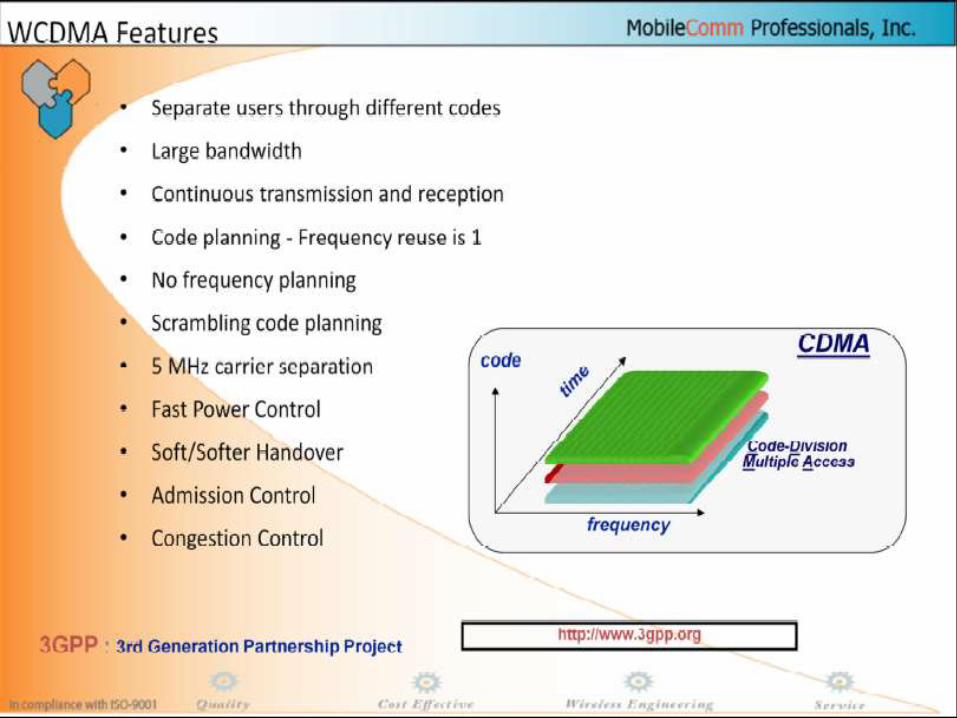
• Here’s how the three most popular radio technologies establish channels:
• • FDMA (Frequency Division Multiple Access)• - Each user is on a different frequency• - A channel is a frequency.• • TDMA (Time Division Multiple Access)• - Each user is on a different window in time (“time slot”)• - A channel is a specific time-slot on a specific frequency.• • W-CDMA (Wide-band Code Division Multiple Access)• - Each user uses the same frequency all the time, but it is mixed
with different• distinguishing code patterns. A channel is a unique (set of) code
pattern(s).

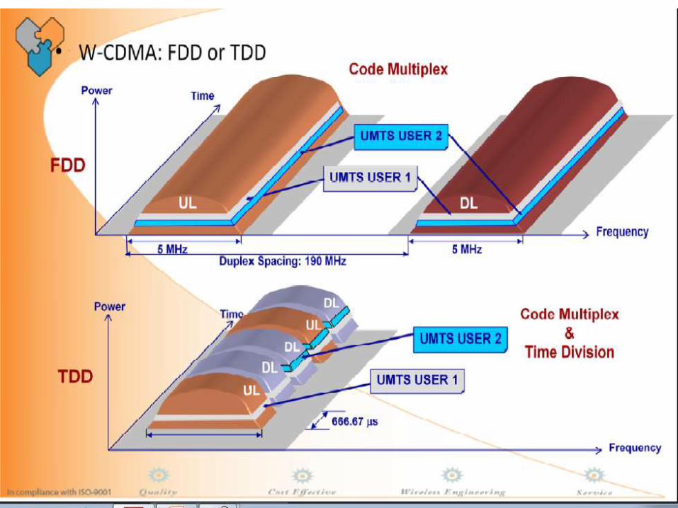

• The possibility to operate in either FDD or TDD mode is allowed for efficient utilization
• of the available spectrum according to the frequency allocation in different regions.
• FDD and TDD are defined as follows:
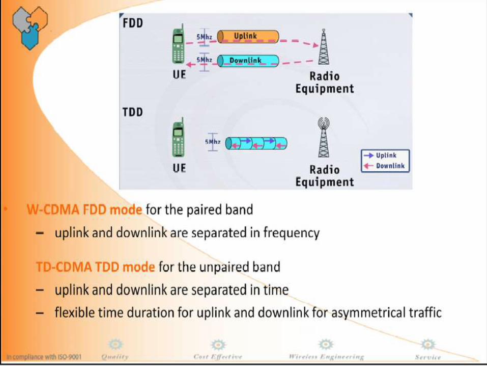
• • FDD
• A duplex method whereby the uplink and downlink transmissions use 2 separate
• frequency bands:
• - Uplink: 1920 MHz - 1980 MHz
• - Downlink: 2110 MHz - 2170 MHz
• Each carrier is 5 MHz wide and the uplink channel is 190 MHz away from the
• downlink. So there are up to 12 pairs of carriers.
• • TDD
• A duplex method whereby the uplink and downlink transmissions are carried over
• same frequency using synchronized time intervals. The carrier still uses a 5 MHz
• band.
• FDD mode is the preferred mode for macro-cellular applications.
• TDD mode is the preferred mode for the unpaired part of the spectrum. Because
• each time-slot can be assigned a different direction, the TDD mode offers a great
• flexibility to manage duplex and asymmetric traffic. The TDD spectrum will be used
• for low mobility coverage in urban areas.


UMTS FRAME
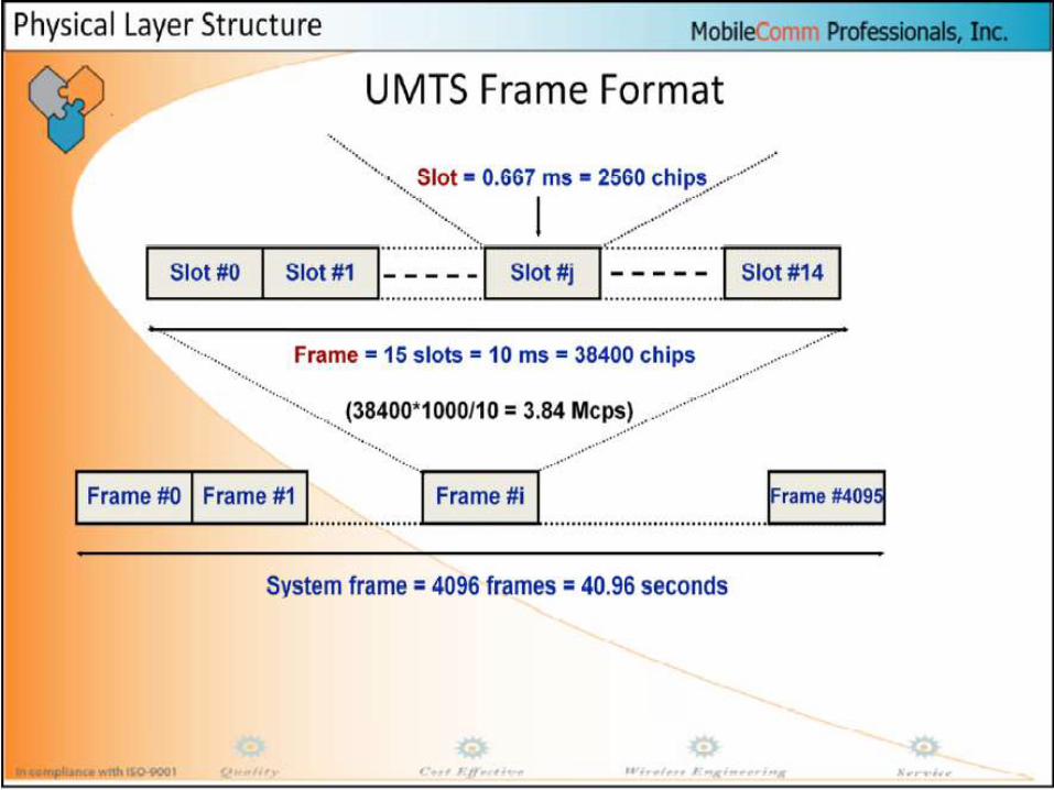
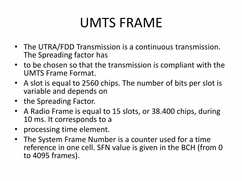
• The UTRA/FDD Transmission is a continuous transmission. The Spreading factor has
• to be chosen so that the transmission is compliant with the UMTS Frame Format.
• A slot is equal to 2560 chips. The number of bits per slot is variable and depends on
• the Spreading Factor.• A Radio Frame is equal to 15 slots, or 38.400 chips, during
10 ms. It corresponds to a• processing time element.• The System Frame Number is a counter used for a time
reference in one cell. SFN value is given in the BCH (from 0 to 4095 frames).


Inner loop pc outer loop pc
• Located in BTS & UE.
• Controls power of dedicated physical channels.
• Inner loop power control
• • The base station compares the measured Eb/Nt with the
• corresponding objective and the mobile station will be ordered to
• decrease the transmission power if the measured Eb/Nt exceeds the
• objective. Otherwise, the mobile station will be ordered to increase
• the transmission power. The adjustment frequency is 1500HZ.
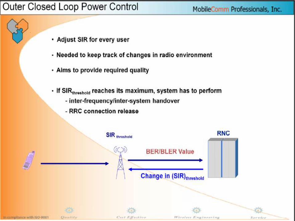
• Outer loop power control
• • Estimate Eb/Nt objective based on the measured Frame Error
• Rate(FER)
• Eb/Nt=bit energy/density of interference power spectrum, similar to signal-to-noise ratio.


Related Documents